JP2006019984A - Telephone exchange device and network telephone system - Google Patents
Telephone exchange device and network telephone systemDownload PDFInfo
- Publication number
- JP2006019984A JP2006019984AJP2004194935AJP2004194935AJP2006019984AJP 2006019984 AJP2006019984 AJP 2006019984AJP 2004194935 AJP2004194935 AJP 2004194935AJP 2004194935 AJP2004194935 AJP 2004194935AJP 2006019984 AJP2006019984 AJP 2006019984A
- Authority
- JP
- Japan
- Prior art keywords
- telephone
- group
- extension group
- telephone terminals
- extension
- Prior art date
- Legal status (The legal status is an assumption and is not a legal conclusion. Google has not performed a legal analysis and makes no representation as to the accuracy of the status listed.)
- Granted
Links
Images


Classifications
- H—ELECTRICITY
- H04—ELECTRIC COMMUNICATION TECHNIQUE
- H04L—TRANSMISSION OF DIGITAL INFORMATION, e.g. TELEGRAPHIC COMMUNICATION
- H04L12/00—Data switching networks
- H04L12/64—Hybrid switching systems
- H04L12/6418—Hybrid transport
- H—ELECTRICITY
- H04—ELECTRIC COMMUNICATION TECHNIQUE
- H04M—TELEPHONIC COMMUNICATION
- H04M3/00—Automatic or semi-automatic exchanges
- H04M3/42—Systems providing special services or facilities to subscribers
- H04M3/42314—Systems providing special services or facilities to subscribers in private branch exchanges
- H—ELECTRICITY
- H04—ELECTRIC COMMUNICATION TECHNIQUE
- H04M—TELEPHONIC COMMUNICATION
- H04M7/00—Arrangements for interconnection between switching centres
- H04M7/006—Networks other than PSTN/ISDN providing telephone service, e.g. Voice over Internet Protocol (VoIP), including next generation networks with a packet-switched transport layer
- H—ELECTRICITY
- H04—ELECTRIC COMMUNICATION TECHNIQUE
- H04L—TRANSMISSION OF DIGITAL INFORMATION, e.g. TELEGRAPHIC COMMUNICATION
- H04L12/00—Data switching networks
- H04L12/64—Hybrid switching systems
- H04L12/6418—Hybrid transport
- H04L2012/6481—Speech, voice
- H—ELECTRICITY
- H04—ELECTRIC COMMUNICATION TECHNIQUE
- H04M—TELEPHONIC COMMUNICATION
- H04M2203/00—Aspects of automatic or semi-automatic exchanges
- H04M2203/20—Aspects of automatic or semi-automatic exchanges related to features of supplementary services
- H04M2203/2044—Group features, e.g. closed user group
Landscapes
- Engineering & Computer Science (AREA)
- Signal Processing (AREA)
- Computer Networks & Wireless Communication (AREA)
- Telephonic Communication Services (AREA)
- Data Exchanges In Wide-Area Networks (AREA)
- Sub-Exchange Stations And Push- Button Telephones (AREA)
Abstract
Description
Translated fromJapaneseこの発明は、例えばIP(Internet Protocol)電話システムにおいて、パケット網上の複数の電話端末に対しグループページング機能等の付加的なサービスを実現できるようにした電話交換装置及びネットワーク電話システムに関する。 The present invention relates to a telephone exchange apparatus and a network telephone system which can realize additional services such as a group paging function for a plurality of telephone terminals on a packet network in an IP (Internet Protocol) telephone system, for example.
近年、パケット網を介して、双方向に画像や音声をパケットデータとして、リアルタイムに送受信するネットワーク電話システム(IP電話システム)が普及し始めている。 2. Description of the Related Art In recent years, network telephone systems (IP telephone systems) that transmit and receive images and sounds as packet data in both directions via a packet network have begun to spread.
このIP電話システムでは、例えばLAN(Local Area Network)にIP電話端末を接続するとともに、LANをゲートウェイを介して公衆網等の一般電話網やインターネットに接続し、IP電話端末及びゲートウェイにおいてプロトコル変換及びデータのフォーマット変換等を行うことにより、IP電話端末相互間及びIP電話端末と一般電話網またはインターネットとの間で音声通信を可能にしている。 In this IP telephone system, for example, an IP telephone terminal is connected to a LAN (Local Area Network), and the LAN is connected to a general telephone network such as a public network or the Internet via a gateway. By performing data format conversion or the like, voice communication can be performed between IP telephone terminals and between an IP telephone terminal and a general telephone network or the Internet.
ところで、上記システムでは、構内交換機に複数の電話端末を接続した通信システムで実施されているグループページング機能についての検討が進んでいる(例えば、特許文献1)。このグループページング機能とは、ある構内交換機に収容される電話端末からの音声信号を複数の電話端末またはスピーカなどの装置に分配し、同時に呼び出す機能である。この場合、タイムスイッチやその他の分配装置等、ハードウェアを用いて発信電話端末からの音声信号を複数の着信電話端末に分配している。
ところが、グループページング機能を上記IP電話システムに適用する場合、音声信号をタイムスイッチに通す必要があるために、音声信号−IPパケット間の変換処理が必要となる。このため、以下のような問題が生じる。 However, when the group paging function is applied to the IP telephone system, since it is necessary to pass the voice signal through the time switch, a conversion process between the voice signal and the IP packet is required. For this reason, the following problems arise.
(1)音声信号−IPパケット変換処理は構内交換機内で行う処理であるため、構内交換機の処理負荷が増大する。 (1) Since the voice signal-IP packet conversion process is performed in the private branch exchange, the processing load of the private branch exchange increases.
(2)音声信号−IPパケット間の変換を行うメディアゲートウェイが、分配先の端末数分必要となり、コストが高くなる。 (2) A media gateway that performs conversion between a voice signal and an IP packet is required for the number of distribution destination terminals, resulting in an increase in cost.
(3)タイムスイッチでは一度に分配できる数が限られているため、限られた数以上の分配先へ音声信号を分配するためには、タイムスイッチを増設する必要があり、コストが高くなる。 (3) Since the number of time switches that can be distributed at one time is limited, in order to distribute audio signals to a limited number or more of distribution destinations, it is necessary to add time switches, which increases costs.
そこで、この発明の目的は、音声パケットを分配すべく端末数に関係なく、グループページング機能を効果的に実現できるようにした電話交換装置及びネットワーク電話システムを提供することにある。 SUMMARY OF THE INVENTION Accordingly, an object of the present invention is to provide a telephone exchange apparatus and a network telephone system that can effectively implement a group paging function regardless of the number of terminals for distributing voice packets.
この発明は、上記目的を達成するために、以下のように構成される。
複数の電話端末を音声パケット伝送用の通信ネットワークを介して接続するとともに、複数の電話端末相互間で通信を行なわせる電話交換装置であって、複数の電話端末を分割して構成した複数の内線グループと、これらの内線グループに属する電話端末との対応関係を表すグループテーブルを格納する記憶手段と、内線グループ宛の接続要求が発生した場合に、グループテーブルを参照して、該当する内線グループの電話端末に対し接続制御を行なう制御手段と、内線グループに対する接続時に、要求元から送られた音声パケットを通信ネットワークを介して該当する内線グループに属する全電話端末に転送する転送手段とを備えるようにしたものである。In order to achieve the above object, the present invention is configured as follows.
A telephone exchange apparatus for connecting a plurality of telephone terminals via a communication network for voice packet transmission and for performing communication between the plurality of telephone terminals, wherein the plurality of extensions are configured by dividing the plurality of telephone terminals. Storage means for storing a group table representing the correspondence relationship between the group and the telephone terminals belonging to these extension groups, and when a connection request directed to the extension group occurs, the group table is referred to and the corresponding extension group Control means for controlling connection to the telephone terminal, and transfer means for transferring a voice packet sent from the request source to all telephone terminals belonging to the corresponding extension group via the communication network when connecting to the extension group. It is a thing.
この構成によれば、内線グループ宛の着信が到来した場合に、グループテーブルを参照して、内線グループに対し着信制御を行なうことができるとともに、発呼者の音声パケットをソフトウェア処理により通信ネットワークを介して該当する内線グループに分配することが可能となる。このため、タイムスイッチは勿論のこと、音声信号−IPパケット変換機能を分配すべき端末数分設ける必要がなく、これにより電話交換装置の処理負担を軽減することができる。 According to this configuration, when an incoming call addressed to the extension group arrives, the incoming call control can be performed for the extension group with reference to the group table, and the communication network is processed by software processing of the caller's voice packet. It is possible to distribute to the corresponding extension group. For this reason, it is not necessary to provide as many time switches as the number of terminals to which voice signal-IP packet conversion functions are to be distributed, thereby reducing the processing load on the telephone exchange device.
制御手段は、前記グループテーブルを参照して、該当する内線グループに属する全電話端末の動作状態を判断し、空きの電話端末に対する接続制御を行なうことを特徴とする。
この構成によれば、音声パケットの分配処理に先立ち、該当する内線グループに属する全電話端末の動作状態をチェックすることができ、空きの電話端末にのみ音声パケットが分配されることになるため、通信ネットワークを多数の電話端末で共用する場合にその有効利用率を高めることができる。The control means refers to the group table to determine the operating state of all telephone terminals belonging to the corresponding extension group, and to perform connection control with respect to an empty telephone terminal.
According to this configuration, prior to voice packet distribution processing, it is possible to check the operating state of all telephone terminals belonging to the corresponding extension group, and voice packets will be distributed only to empty telephone terminals. When a communication network is shared by many telephone terminals, the effective utilization rate can be increased.
転送手段は、該当する内線グループに属する全電話端末に対する音声パケットの転送中に、他の電話端末から該内線グループ中の電話端末を指定した接続要求が発生した場合に、指定された電話端末に対する音声パケットの転送処理を停止することを特徴とする。
この構成によれば、内線グループに対する音声パケットの転送中に、該内線グループに属する電話端末を指定した着信が発生した場合に、該電話端末を内線グループから外して音声パケットの分配処理を行なうことができる。このため、グループページング機能により内線グループ内の全電話端末を占有することなく、該内線グループ中のある電話端末を指定した緊急の顧客からの着信が到来した場合に、該電話端末に対し発信端末へ優先的に接続することができ、これによりきめ細かな応対サービスを実現できる。When a connection request for specifying a telephone terminal in the extension group is generated from another telephone terminal during transfer of voice packets to all telephone terminals belonging to the corresponding extension group, the transfer means applies to the specified telephone terminal. The voice packet transfer process is stopped.
According to this configuration, when an incoming call specifying a telephone terminal belonging to the extension group occurs during transfer of the voice packet to the extension group, the telephone terminal is removed from the extension group and the voice packet is distributed. Can do. For this reason, when an incoming call from an emergency customer who designates a certain telephone terminal in the extension group arrives without occupying all the telephone terminals in the extension group by the group paging function, the calling terminal is sent to the telephone terminal. Can be preferentially connected to each other, thereby realizing a detailed service.
複数の電話端末を音声パケット伝送用の通信ネットワークを介して接続するとともに、複数の電話端末相互間で通信を行なわせる電話交換装置と、通信ネットワークに接続され、前記電話交換装置の機能の一部を実行するサーバ装置とを備えたネットワーク電話システムであって、電話交換装置は、複数の電話端末を分割して構成した複数の内線グループと、これらの内線グループに属する電話端末との対応関係を表すグループテーブルを格納する記憶手段と、内線グループ宛の接続要求が発生した場合に、グループテーブルを参照して、該当する内線グループを表す情報を前記サーバ装置に送信する送信手段とを備え、サーバ装置は、電話交換装置から送られた内線グループを表す情報に基づいて、該当する内線グループの電話端末に対し接続制御を行なう制御手段と、内線グループに対する接続時に、要求元から送られた音声パケットを通信ネットワークを介して該当する内線グループに属する全電話端末に分配する分配手段とを備えるようにしたものである。 A plurality of telephone terminals are connected via a communication network for voice packet transmission, and a telephone exchange device for communicating between the plurality of telephone terminals, and a part of the function of the telephone exchange device connected to the communication network The telephone exchange apparatus has a correspondence relationship between a plurality of extension groups formed by dividing a plurality of telephone terminals and telephone terminals belonging to these extension groups. A storage means for storing a group table to be represented, and a transmission means for referring to the group table and transmitting information representing the corresponding extension group to the server device when a connection request addressed to the extension group occurs. Based on the information indicating the extension group sent from the telephone exchange device, the device will respond to the telephone terminal of the corresponding extension group. Control means for performing continuous control and distribution means for distributing voice packets sent from the request source to all telephone terminals belonging to the corresponding extension group via the communication network when connected to the extension group. is there.
この構成によれば、例えばグループページング機能の処理を伴う交換サービス制御を実行する場合に、グループページング機能の処理を電話交換装置に頼らずにサーバ装置で分担して実行することが可能となり、これによりグループページング機能の処理を伴う交換サービス制御を電話交換装置とサーバ装置とが協働して効率良く実行することができる。 According to this configuration, for example, when switching service control involving processing of the group paging function is executed, the processing of the group paging function can be shared and executed by the server device without depending on the telephone switching device. As a result, the switching service control involving the processing of the group paging function can be efficiently executed in cooperation between the telephone switching device and the server device.
以上詳述したようにこの発明によれば、音声パケットを分配すべく端末数に関係なく、グループページング機能を効果的に実現できるようにした電話交換装置及びネットワーク電話システムを提供することができる。 As described in detail above, according to the present invention, it is possible to provide a telephone exchange apparatus and a network telephone system that can effectively realize a group paging function regardless of the number of terminals for distributing voice packets.
以下、この発明の実施形態について図面を参照して詳細に説明する。
(第1の実施形態)
図1は、この発明の第1の実施形態に係わるネットワーク電話システムを示す概略構成図である。Hereinafter, embodiments of the present invention will be described in detail with reference to the drawings.
(First embodiment)
FIG. 1 is a schematic configuration diagram showing a network telephone system according to a first embodiment of the present invention.
このシステムは、LAN(Local Area Network)1を有する。LAN1には、複数の電話端末T11〜T1i(iは自然数)が接続されている。なお、電話端末T11〜T1iには、通話処理機能とメディア情報処理機能とを備えたIP電話機の他に、パーソナル・コンピュータと、携帯電話機、音声通信機能と無線LANアクセス機能とを備えた携帯情報端末とがある。 This system has a LAN (Local Area Network) 1. A plurality of telephone terminals T11 to T1i (i is a natural number) are connected to the LAN1. Note that the telephone terminals T11 to T1i include a personal computer, a cellular phone, a voice communication function and a wireless LAN access function in addition to an IP telephone having a call processing function and a media information processing function. There is a terminal.
また、LAN1には、主装置2Aが接続されている。主装置2Aは、LAN1上に接続された複数の電話端末T11〜T1i相互間、複数の電話端末T11〜T1iと公衆網NWとの間を接続する。 The
上記主装置2Aは、この発明に係わる機能として次のような機能を有している。図2はその構成を示すブロック図である。
すなわち、主装置2Aは、網インタフェース(I/F)部21と、LANインタフェース(I/F)部22と、音声処理部23と、制御部24Aと、記憶部25とを備えている。これら網インタフェース部21、LANインタフェース部22、音声処理部23、制御部24A及び記憶部25は、データハイウェイ26を介して互いに接続されている。
また、網インタフェース部21、LANインタフェース部22及び音声処理部23は、PCMハイウェイ27を介して互いに接続されている。The
That is, the
The
網インタフェース部21には、公衆網NWが必要に応じて接続される。網インタフェース部21は、接続された公衆網NWとPCMハイウェイ27との間でインタフェース処理を行なう。また、網インタフェース部21は、上記インタフェース処理に係わる種々の制御情報の授受を、データハイウェイ26を介して制御部24Aとの間で行う。 A public network NW is connected to the
LANインタフェース部22には、LAN1が必要に応じて接続される。LANインタフェース部22は、接続されたLAN1とPCMハイウェイ27との間でインタフェース処理を行なう。また、LANインタフェース部22は、上記インタフェース処理に係わる種々の制御情報の授受を、データハイウェイ26を介して制御部24Aとの間で行う。 The
音声処理部23は、LAN1から受信した音声パケットを公衆網NWで取り扱い可能な音声信号に変換して公衆網NWへ送信する機能を有する。
制御部24Aは、CPU、ROM、RAMなどを有して構成され、ソフトウェア処理により主装置2Aの各部の制御を行う。The
The control unit 24A includes a CPU, a ROM, a RAM, and the like, and controls each unit of the
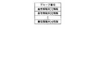
記憶部25は、制御部24Aの接続制御に必要なルーティング情報等を格納しており、さらに内線グループテーブル251を格納している。このうち内線グループテーブル251は、例えば図3に示すように、電話端末T11〜T1iを分割して構成した複数の内線グループTG1,TG2と、これらの内線グループTG1,TG2に属する電話端末T11〜T1iとの対応関係を記憶したものである。 The
これに対し、制御部24Aは、交換制御部241と、IPパケット転送部242とを備えている。
交換制御部241は、内線グループ宛のグループページング要求が到来した場合に、内線グループテーブル251を参照して、該当する内線グループTG1,TG2に対する着信制御を行なう。On the other hand, the control unit 24A includes an
When a group paging request addressed to the extension group arrives, the
IPパケット転送部242は、内線グループTG1,TG2に対する接続時に、要求元から送られたIPパケットをLAN1を介して該当する例えば内線グループTG1の電話端末T11,T12,T13に分配して転送する。 When connecting to the extension groups TG1 and TG2, the IP
次に、以上のように構成されたシステムの動作について説明する。
いま、図4に示すように、公衆網NWから内線グループTG1に対するグループページングの要求信号が主装置2に到来したとする。そうすると、主装置2は内線グループテーブル251の記憶内容に基づいて、内線グループTG1に属する電話端末T11,T12,T13に対しそれぞれ着信データを転送して着信報知を行なわせる。Next, the operation of the system configured as described above will be described.
Now, as shown in FIG. 4, it is assumed that a group paging request signal for the extension group TG1 has arrived at the main apparatus 2 from the public network NW. Then, main apparatus 2 transfers incoming data to telephone terminals T11, T12, and T13 belonging to extension group TG1 based on the stored contents of extension group table 251 to perform incoming call notification.
そして、着信報知に対し各電話端末T11,T12,T13のユーザが応答操作を行なうと、発信元の外部電話端末と着信先の電話端末T11,T12,T13との間には通信路が形成され、音声通信が可能となる。 When the user of each telephone terminal T11, T12, T13 responds to the incoming call notification, a communication path is formed between the caller external telephone terminal and the callee telephone terminals T11, T12, T13. Voice communication is possible.
すなわち、外部電話端末から送信された音声信号は公衆網NWを介して主装置2Aに送信される。主装置2Aは、受信した音声信号をIPパケットに変換し、このIPパケットをLAN1を介して電話端末T11,T12,T13へ伝送する。このIPパケットを受信した電話端末T11,T12,T13では、IPパケットから音声データが抽出され、この音声データがアナログ音声信号に変換された後スピーカに供給されて拡声出力される。 That is, the audio signal transmitted from the external telephone terminal is transmitted to the
以上のように上記第1の実施形態では、内線グループTG1宛のグループページングの要求信号が主装置2Aに到来した場合に、主装置2Aでは内線グループテーブル251の記憶内容を参照して、内線グループTG1に対し着信制御を行なうとともに、発呼者のIPパケットをソフトウェア処理によりLAN1を介して該当する内線グループTG1の電話端末T11,T12,T13に分配するようにしている。 As described above, in the first embodiment, when a group paging request signal addressed to the extension group TG1 arrives at the
従って、タイムスイッチは勿論のこと、音声信号−IPパケット変換機能を分配すべき端末数分設ける必要がなく、これにより主装置2Aの処理負担を軽減することができる。 Therefore, it is not necessary to provide as many time switches as the number of terminals to which voice signal-IP packet conversion functions are to be distributed, thereby reducing the processing load on the
(第2の実施形態)
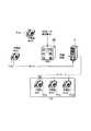
図5は、この発明の第2の実施形態に係わるネットワーク電話システムを示す概略構成図である。
このシステムでは、LAN1に主装置2Bの機能の一部を実行する分配サーバ3を接続するようにしている。このとき、主装置2Bは、図6に示す機能構成となる。(Second Embodiment)
FIG. 5 is a schematic diagram showing a network telephone system according to the second embodiment of the present invention.
In this system, a
主装置2Bにおいて、制御部24Bは、通信処理部243を備えている。
通信処理部243は、内線グループ宛の着信が到来した場合に、分配サーバ3との間でLAN1を介して制御情報の通信を行ない、この通信に従って該当する内線グループTG1,TG2に対する着信制御を行なう。このとき、該当する内線グループTG1の電話端末T11,T12,T13を示す識別情報を内線グループテーブル251から読み出して、分配サーバ3に送信する。In the
When an incoming call addressed to the extension group arrives, the
図7は、分配サーバ3の機能構成を示すブロック図である。
すなわち、分配サーバ3は、通信管理部31と、グループページング制御部32と、グループページング処理部33と、データベース34とを備えている。FIG. 7 is a block diagram showing a functional configuration of the
That is, the
通信管理部31は、主装置2Bから図8に示すような内線グループ宛のグループページングの要求信号が到来した場合に、要求信号に付加されるヘッダ情報からグループページング開始であるか否かを判定し、グループページング開始である場合に、要求信号から図9に示すグループ設定情報を抽出してデータベース34に登録する。このとき、グループページング開始の旨をグループページング制御部32に通知する。 When the group paging request signal addressed to the extension group as shown in FIG. 8 arrives from the
グループページング制御部32は、グループページング開始情報を受信すると、データベース34に登録されたグループ設定情報に基づいて、発信端末と着信先となる内線グループTG1内の電話端末T11,T12,T13との間を接続するように、グループページング処理部33を制御する。 When the group
グループページング処理部33は、グループページング制御部32の制御によって接続指示を受けると、発信端末と着信先となる内線グループTG1内の電話端末T11,T12,T13との間を接続し、発信端末から送られてくるIPパケットを電話端末T11,T12,T13に分配して送信する。 When the group
次に、以上のように構成されたシステムの動作について説明する。
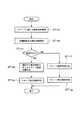
いま、図10に示すように、電話端末T14において内線グループTG1宛のグループベージング要求がなされ、これに応じて主装置2Bにグループページングの要求信号が到来したとする。すると、主装置2Bは、図11に示す制御処理を実行する。Next, the operation of the system configured as described above will be described.
Now, as shown in FIG. 10, it is assumed that a group paging request addressed to the extension group TG1 is made at the telephone terminal T14, and in response to this, a group paging request signal arrives at the
主装置2Bにおいて、制御部24Bは、内線グループテーブル251から内線グループTG1に属する電話端末T11,T12,T13を検索し(ステップST11a)、これら電話端末T11,T12,T13の動作状態の判定を行ない(ステップST11b)、通話中であるか否かの判断を行なう(ステップST11c)。 In the
このとき、電話端末T11が電話端末T15と通話中であったとする。すると、制御部24Bは通話中の電話端末T11を外したグループ設定情報を作成し(ステップST11d)、このグループ設定情報を含むグループページング要求信号を分配サーバ3に送信する(ステップST11e)。 At this time, it is assumed that the telephone terminal T11 is in a call with the telephone terminal T15. Then, the
一方、電話端末T11,T12,T13が全て空きであるならば(No)、制御部24Bは電話端末T11,T12,T13を含むグループ設定情報を作成し(ステップST11f)、このグループ設定情報を含むグループページング要求信号を分配サーバ3に送信する(ステップST11g)。 On the other hand, if the telephone terminals T11, T12, and T13 are all empty (No), the
なお、電話端末T12が発信中であったり、着信中であった場合にも、制御部24Bは電話端末T12を外したグループ設定情報を作成する。 Even when the telephone terminal T12 is making a call or receiving a call, the
グループページング要求信号を受信した分配サーバ3は、グループページング要求信号に含まれるグループ設定情報に基づいて、電話端末T14と電話端末T12,T13との間に通信路を形成し、電話端末T14から送られたIPパケットを電話端末T12,T13に転送する。このとき、時分割によりIPパケットが電話端末T12,T13に送られる。 The
以上のように上記第2の実施形態では、例えばグループページング機能の処理を伴う交換サービス制御を実行する場合に、グループページング機能の処理を主装置2Bに頼らずに分配サーバ3で分担して実行することが可能となり、これによりグループページング機能の処理を伴う交換サービス制御を主装置2Bと分配サーバ3とが協働して効率良く実行することができる。 As described above, in the second embodiment, for example, when switching service control involving group paging function processing is executed, the group server paging function processing is shared and executed by the
また、上記第2の実施形態によれば、主装置2Bにおいて、IPパケットの分配処理に先立ち、該当する内線グループTG1に属する全電話端末T11,T12,T13の動作状態を判定するようにして、空きの電話端末T12,T13にのみIPパケットを分配させるようにしている。したがって、LAN1を多数の電話端末T11,T12,T13,T14で共用する場合にその有効利用率を高めることができる。 Further, according to the second embodiment, in the
(第3の実施形態)
図12は、この発明の第3の実施形態において、IPパケットの分配動作を示すシーケンス図である。なお、図10と同一部分には同一符号を付して詳細な説明を省略する。
いま、電話端末T15と電話端末T11,T12,T13との間でグループページング機能を実行しているものとする。(Third embodiment)
FIG. 12 is a sequence diagram showing an IP packet distribution operation in the third embodiment of the present invention. Note that the same parts as those in FIG.
Assume that the group paging function is executed between the telephone terminal T15 and the telephone terminals T11, T12, and T13.
この状態で、電話端末T14から電話端末T11を指定した着信信号が主装置2Bに到来したとする。すると、主装置2Bは内線グループTG1を示す情報と、電話端末T11を示す情報とをグループページング処理停止を表す制御情報に含めて分配サーバ3に送信する。 In this state, it is assumed that an incoming signal designating the telephone terminal T11 from the telephone terminal T14 arrives at the
分配サーバ3では、制御情報を受信すると、電話端末T11の通信路を解放し、IPパケットの分配を停止する。以後、主装置2Bは、着信データを電話端末T11に転送して着信報知を行なわせ、この着信報知に応答した際に、電話端末T14と電話端末T11との間の通信路を形成する。 When receiving the control information, the
以上のように上記第3の実施形態では、内線グループTG1に対するグループページング機能実行中に、該内線グループTG1に属する電話端末T11を指定した着信信号が主装置2Bに到来した場合に、該電話端末T11を内線グループTG1から外してIPパケットの分配処理を継続させるようにしている。 As described above, in the third embodiment, when the incoming signal specifying the telephone terminal T11 belonging to the extension group TG1 arrives at the
従って、グループページング機能により内線グループTG1内の全電話端末T11,T12,T13を占有することなく、該内線グループTG1中のある電話端末T11を指定した緊急の着信が到来した場合に、該電話端末T11に対し発信元の電話端末T14へ優先的に接続することができ、これによりきめ細かな応対サービスを実現できる。 Therefore, when an emergency incoming call specifying a certain telephone terminal T11 in the extension group TG1 arrives without occupying all the telephone terminals T11, T12, T13 in the extension group TG1 by the group paging function, the telephone terminal It is possible to preferentially connect to the telephone terminal T14 as a call source with respect to T11, thereby realizing a detailed service.
(その他の実施形態)
この発明は、上記各実施形態に限定されるものではない。例えば、上記第2の実施形態の如く電話端末の動作状態に応じたグループページング機能を第1の実施形態に適用してもよい。また、上記第1の実施形態において、グループページング機能の実行中に内線グループ内の電話端末宛の着信が到来した場合に、その電話端末をグループから外すようにしてもよい。(Other embodiments)
The present invention is not limited to the above embodiments. For example, a group paging function according to the operating state of the telephone terminal as in the second embodiment may be applied to the first embodiment. In the first embodiment, when an incoming call addressed to a telephone terminal in the extension group arrives during execution of the group paging function, the telephone terminal may be removed from the group.
また、上記第3の実施形態では、グループページング機能の実行中に、主装置から分配サーバに送信されるグループ設定情報中の端末リストが空きであった場合に、分配サーバは、制御情報で指定されたグループに属する全ての電話端末へのIPパケット分配処理を停止するようにもできる。 In the third embodiment, if the terminal list in the group setting information transmitted from the main apparatus to the distribution server is empty during execution of the group paging function, the distribution server is designated by the control information. It is also possible to stop the IP packet distribution process to all the telephone terminals belonging to the specified group.
その他、システムの構成及び種類、主装置の構成、分配サーバの構成、グループページング機能の実行手順等についても、この発明の要旨を逸脱しない範囲で種々変形して実施できる。 In addition, the system configuration and type, the main device configuration, the distribution server configuration, the group paging function execution procedure, and the like can be implemented with various modifications without departing from the scope of the present invention.
1…LAN、2A,2B…主装置、3…分配サーバ、21…網インタフェース部、22…LANインタフェース部、23…音声処理部、24A,24B…制御部、25…記憶部、26…データハイウェイ、27…PCMハイウェイ、31…通信管理部、32…グループページング制御部、33…グループページング処理部、34…データベース、241…交換制御部、242…IPパケット転送部、243…通信処理部、251…内線グループテーブル、T11〜T1i…電話端末、NW…公衆網。 DESCRIPTION OF
Claims (6)
Translated fromJapanese前記複数の電話端末を分割して構成した複数の内線グループと、これらの内線グループに属する電話端末との対応関係を表すグループテーブルを格納する記憶手段と、
前記内線グループ宛の接続要求が発生した場合に、前記グループテーブルを参照して、該当する内線グループの電話端末に対し接続制御を行なう制御手段と、
前記内線グループに対する接続時に、要求元から送られた音声パケットを前記通信ネットワークを介して該当する内線グループに属する全電話端末に転送する転送手段とを具備したことを特徴とする電話交換装置。A telephone exchange device for connecting a plurality of telephone terminals via a communication network for voice packet transmission and allowing communication between the plurality of telephone terminals,
Storage means for storing a plurality of extension groups configured by dividing the plurality of telephone terminals and a group table representing a correspondence relationship between the telephone terminals belonging to these extension groups;
When a connection request addressed to the extension group occurs, control means for performing connection control on the telephone terminal of the corresponding extension group with reference to the group table;
A telephone exchange apparatus comprising: a transfer unit configured to transfer a voice packet sent from a request source to all telephone terminals belonging to the corresponding extension group via the communication network when connected to the extension group.
前記電話交換装置は、
前記複数の電話端末を分割して構成した複数の内線グループと、これらの内線グループに属する電話端末との対応関係を表すグループテーブルを格納する記憶手段と、
前記内線グループ宛の接続要求が発生した場合に、前記グループテーブルを参照して、該当する内線グループを表す情報を前記サーバ装置に送信する送信手段とを備え、
前記サーバ装置は、
前記電話交換装置から送られた内線グループを表す情報に基づいて、該当する内線グループの電話端末に対し接続制御を行なう制御手段と、
前記内線グループに対する接続時に、要求元から送られた音声パケットを前記通信ネットワークを介して該当する内線グループに属する全電話端末に分配する分配手段とを備えたことを特徴とするネットワーク電話システム。A plurality of telephone terminals are connected via a communication network for voice packet transmission, and a telephone exchange device for communicating between the plurality of telephone terminals, and a function of the telephone exchange device connected to the communication network A network telephone system including a server device for executing a part of the network phone system;
The telephone exchange device
Storage means for storing a plurality of extension groups configured by dividing the plurality of telephone terminals and a group table representing a correspondence relationship between the telephone terminals belonging to these extension groups;
When a connection request addressed to the extension group occurs, the group table is referred to, and transmission means for transmitting information representing the corresponding extension group to the server device,
The server device
Control means for controlling connection to the telephone terminals of the corresponding extension group based on the information representing the extension group sent from the telephone exchange device;
A network telephone system comprising distribution means for distributing a voice packet sent from a request source to all telephone terminals belonging to the corresponding extension group via the communication network when connected to the extension group.
Priority Applications (3)
| Application Number | Priority Date | Filing Date | Title |
|---|---|---|---|
| JP2004194935AJP4189360B2 (en) | 2004-06-30 | 2004-06-30 | Telephone exchange device and network telephone system |
| US11/170,679US20060002376A1 (en) | 2004-06-30 | 2005-06-30 | Telephone exchange and network telephone system |
| GB0513408AGB2416644B (en) | 2004-06-30 | 2005-06-30 | Telephone exchange and network telephone system |
Applications Claiming Priority (1)
| Application Number | Priority Date | Filing Date | Title |
|---|---|---|---|
| JP2004194935AJP4189360B2 (en) | 2004-06-30 | 2004-06-30 | Telephone exchange device and network telephone system |
Publications (2)
| Publication Number | Publication Date |
|---|---|
| JP2006019984Atrue JP2006019984A (en) | 2006-01-19 |
| JP4189360B2 JP4189360B2 (en) | 2008-12-03 |
Family
ID=34858554
Family Applications (1)
| Application Number | Title | Priority Date | Filing Date |
|---|---|---|---|
| JP2004194935AExpired - Fee RelatedJP4189360B2 (en) | 2004-06-30 | 2004-06-30 | Telephone exchange device and network telephone system |
Country Status (3)
| Country | Link |
|---|---|
| US (1) | US20060002376A1 (en) |
| JP (1) | JP4189360B2 (en) |
| GB (1) | GB2416644B (en) |
Cited By (1)
| Publication number | Priority date | Publication date | Assignee | Title |
|---|---|---|---|---|
| WO2021235149A1 (en) | 2020-05-20 | 2021-11-25 | Necプラットフォームズ株式会社 | Relay device, communication system, relaying method, and program |
Families Citing this family (2)
| Publication number | Priority date | Publication date | Assignee | Title |
|---|---|---|---|---|
| CN105684405B (en)* | 2013-11-07 | 2018-11-30 | 艾可慕株式会社 | The trunking method of relay, sound communication system, recording medium and voice signal |
| DE102014108295A1 (en)* | 2014-06-12 | 2015-12-17 | Osram Opto Semiconductors Gmbh | Light-emitting semiconductor device |
Family Cites Families (9)
| Publication number | Priority date | Publication date | Assignee | Title |
|---|---|---|---|---|
| JPS61281660A (en)* | 1985-06-06 | 1986-12-12 | Nec Corp | Call pick-up system |
| JPH0514256A (en)* | 1991-07-08 | 1993-01-22 | Nec Corp | Group calling system |
| JPH07245654A (en)* | 1994-03-03 | 1995-09-19 | Fujitsu Ltd | Electronic exchange |
| US6683870B1 (en)* | 1997-02-10 | 2004-01-27 | Mci Communications Corporation | Method and system for multicasting call notifications |
| US6236716B1 (en)* | 1998-02-11 | 2001-05-22 | Nortel Networks Ltd | Call parking and paging system and method of operation |
| US6614781B1 (en)* | 1998-11-20 | 2003-09-02 | Level 3 Communications, Inc. | Voice over data telecommunications network architecture |
| US6956828B2 (en)* | 2000-12-29 | 2005-10-18 | Nortel Networks Limited | Apparatus and method for packet-based media communications |
| US7433925B1 (en)* | 2003-08-29 | 2008-10-07 | Cisco Technology, Inc. | Method and apparatus for measuring health and performance of a messaging system |
| JP4372560B2 (en)* | 2004-01-05 | 2009-11-25 | 東日本電信電話株式会社 | IP telephone system, communication control method, and computer program therefor |
- 2004
- 2004-06-30JPJP2004194935Apatent/JP4189360B2/ennot_activeExpired - Fee Related
- 2005
- 2005-06-30GBGB0513408Apatent/GB2416644B/ennot_activeExpired - Fee Related
- 2005-06-30USUS11/170,679patent/US20060002376A1/ennot_activeAbandoned
Cited By (2)
| Publication number | Priority date | Publication date | Assignee | Title |
|---|---|---|---|---|
| WO2021235149A1 (en) | 2020-05-20 | 2021-11-25 | Necプラットフォームズ株式会社 | Relay device, communication system, relaying method, and program |
| US12052388B2 (en) | 2020-05-20 | 2024-07-30 | Nec Platforms, Ltd. | Relay apparatus, communication system, relay method, and program |
Also Published As
| Publication number | Publication date |
|---|---|
| US20060002376A1 (en) | 2006-01-05 |
| GB2416644B (en) | 2008-12-17 |
| GB0513408D0 (en) | 2005-08-03 |
| GB2416644A (en) | 2006-02-01 |
| JP4189360B2 (en) | 2008-12-03 |
Similar Documents
| Publication | Publication Date | Title |
|---|---|---|
| US7596131B1 (en) | Advanced voice communication feature transparency in a telecommunications network | |
| JP2006229820A (en) | VoIP gateway device | |
| JP2005191799A (en) | Media gateway and automatic call forwarding service system | |
| JP2004357217A (en) | Telephone exchange and telephone exchange system | |
| JP2007081759A (en) | COMMUNICATION SYSTEM, PRESENCE SERVER, AND COMMUNICATION METHOD USED FOR THEM | |
| US20040114575A1 (en) | Exchange system | |
| TWI279123B (en) | Automatic call distribution with computer telephony interface enablement | |
| JP2005184351A (en) | VoIP gateway device and method for controlling call arrival and departure in VoIP gateway device | |
| JP4189360B2 (en) | Telephone exchange device and network telephone system | |
| JP4381405B2 (en) | Telephone exchange system | |
| US20100266113A1 (en) | Telephone call maintenance with single party for subsequent reconnection | |
| JP4861491B2 (en) | Telephone system, telephone exchange apparatus, and connection control method used in telephone exchange apparatus | |
| JP4594569B2 (en) | Voice packet communication system | |
| JP3737627B2 (en) | Communication system with voice service function | |
| JP2006101528A (en) | Detection of looping communication channel | |
| JP2011097469A (en) | Telephone system and exchange apparatus therefor | |
| KR100587945B1 (en) | Method and system of providing call transfer service | |
| JP2007124036A (en) | Server device | |
| JP4843708B2 (en) | Telephone exchange system, telephone exchange device and telephone terminal | |
| JP2005167421A (en) | VOICE COMMUNICATION SYSTEM, COMMUNICATION DEVICE FOR THE VOICE COMMUNICATION SYSTEM, AND TELEPHONE EXCHANGE DEVICE | |
| JP2007124037A (en) | Telephone exchange device and incoming call control method for telephone exchange device | |
| JP3974310B2 (en) | Multimedia communication system | |
| JP2002218055A (en) | Exchange control system and exchange control method | |
| JP2004304630A (en) | Key telephone system | |
| JP2022149475A (en) | CALL RECORDING SYSTEM AND CALL RECORDING METHOD |
Legal Events
| Date | Code | Title | Description |
|---|---|---|---|
| A621 | Written request for application examination | Free format text:JAPANESE INTERMEDIATE CODE: A621 Effective date:20060607 | |
| A977 | Report on retrieval | Free format text:JAPANESE INTERMEDIATE CODE: A971007 Effective date:20071015 | |
| A131 | Notification of reasons for refusal | Free format text:JAPANESE INTERMEDIATE CODE: A131 Effective date:20071225 | |
| A521 | Request for written amendment filed | Free format text:JAPANESE INTERMEDIATE CODE: A523 Effective date:20080221 | |
| TRDD | Decision of grant or rejection written | ||
| A01 | Written decision to grant a patent or to grant a registration (utility model) | Free format text:JAPANESE INTERMEDIATE CODE: A01 Effective date:20080909 | |
| A01 | Written decision to grant a patent or to grant a registration (utility model) | Free format text:JAPANESE INTERMEDIATE CODE: A01 | |
| A61 | First payment of annual fees (during grant procedure) | Free format text:JAPANESE INTERMEDIATE CODE: A61 Effective date:20080912 | |
| FPAY | Renewal fee payment (event date is renewal date of database) | Free format text:PAYMENT UNTIL: 20110919 Year of fee payment:3 | |
| LAPS | Cancellation because of no payment of annual fees |