JP2006015078A - Medical apparatus - Google Patents
Medical apparatusDownload PDFInfo
- Publication number
- JP2006015078A JP2006015078AJP2004198529AJP2004198529AJP2006015078AJP 2006015078 AJP2006015078 AJP 2006015078AJP 2004198529 AJP2004198529 AJP 2004198529AJP 2004198529 AJP2004198529 AJP 2004198529AJP 2006015078 AJP2006015078 AJP 2006015078A
- Authority
- JP
- Japan
- Prior art keywords
- switch
- endoscope
- camera head
- slider
- switches
- Prior art date
- Legal status (The legal status is an assumption and is not a legal conclusion. Google has not performed a legal analysis and makes no representation as to the accuracy of the status listed.)
- Withdrawn
Links
- 238000001514detection methodMethods0.000claimsdescription48
- 238000012545processingMethods0.000claimsdescription26
- 230000002093peripheral effectEffects0.000abstractdescription9
- 238000003384imaging methodMethods0.000description37
- 230000003287optical effectEffects0.000description9
- 210000003813thumbAnatomy0.000description9
- 210000003811fingerAnatomy0.000description8
- 238000012905input functionMethods0.000description8
- 238000003780insertionMethods0.000description7
- 230000037431insertionEffects0.000description7
- 230000000694effectsEffects0.000description6
- 238000012986modificationMethods0.000description3
- 230000004048modificationEffects0.000description3
- 238000004659sterilization and disinfectionMethods0.000description3
- 239000000758substrateSubstances0.000description3
- 230000000249desinfective effectEffects0.000description2
- 238000005286illuminationMethods0.000description2
- 239000007788liquidSubstances0.000description2
- 230000001954sterilising effectEffects0.000description2
- 241000283690Bos taurusSpecies0.000description1
- 230000002421anti-septic effectEffects0.000description1
- 239000003795chemical substances by applicationSubstances0.000description1
- 238000010586diagramMethods0.000description1
- 230000001151other effectEffects0.000description1
- 238000012360testing methodMethods0.000description1
- XLYOFNOQVPJJNP-UHFFFAOYSA-NwaterSubstancesOXLYOFNOQVPJJNP-UHFFFAOYSA-N0.000description1
Images


Landscapes
- Surgical Instruments (AREA)
- Endoscopes (AREA)
Abstract
Description
Translated fromJapanese本発明は、医療用具の操作に関する信号と医療用具によって撮像された映像信号の処理設定に関する信号との少なくとも一方の信号を制御手段に入力するスイッチを医療用具の手元側に有する医療用装置に関する。 The present invention relates to a medical device having a switch on the hand side of a medical device that inputs at least one of a signal related to operation of the medical device and a signal related to processing setting of a video signal imaged by the medical device to a control unit.
従来、この種の医療用装置として、内視鏡装置が広く知られている。内視鏡装置は、細長の挿入部を体腔内や管路内等に挿入することにより、体腔内や管路内等の被検部位を観察できるものであり、このような内視鏡装置は、例えば、図15に示すような構成を有している。 Conventionally, an endoscope apparatus is widely known as this type of medical apparatus. An endoscope apparatus can observe a test site such as a body cavity or a duct by inserting an elongated insertion portion into a body cavity or a duct. Such an endoscope apparatus is For example, it has a structure as shown in FIG.
図15に示すように、内視鏡装置101は、細長の挿入部を体腔内や管路内等に挿入して得た被写体像が結像される図示しない対物レンズを有する内視鏡102と、該内視鏡102に照射光を供給する図示しない光源装置と、内視鏡102の基端部に着脱自在に取り付けられ内視鏡102の上記対物レンズに結像された被写体像を撮像する内視鏡用撮像装置103と、該内視鏡用撮像装置103で撮像された撮像信号をモニタ表示できるよう映像信号に変換する周辺装置であるビデオプロセッサ104と、このビデオプロセッサ104で変換された映像信号が表示される周辺装置であるモニタ装置105とを有して主要部が構成されている。 As shown in FIG. 15, an
内視鏡用撮像装置103は、内視鏡102の基端部の接眼部111に着脱自在であるカメラヘッド121と、該カメラヘッド121とビデオプロセッサ104とを接続するケーブル122と、該ケーブル122の端部に設けられビデオプロセッサ104に着脱自在であるコネクタ123とを有して主要部が構成されている。 An
カメラヘッド121の内部に、内視鏡102の図示しない対物レンズに結像された被写体像を撮像するCCD等の撮像素子124が設けられており、該撮像素子124から、撮像信号等を伝送するための信号線125が延出され、該信号線125の他端は、ケーブル122内を挿通されてコネクタ123に電気的に接続されている。 An
ビデオプロセッサ104は、撮像素子124からケーブル122を介して入力された撮像信号をモニタ表示できるよう映像信号に変換する、即ち映像信号処理機能を実行する映像信号処理回路131と、該映像信号処理回路131が実行する映像信号処理機能の動作を設定する動作設定操作スイッチ133と、映像信号処理回路131において変換された映像信号をモニタ装置105へ伝送するモニタケーブル132とを有して構成されている。 The
このような構成を有する内視鏡装置101は、内視鏡102の図示しない対物レンズに結像された被写体像が、内視鏡用撮像装置103のカメラヘッド121内の撮像素子124により撮像され、該撮像された被写体像の撮像信号は、ケーブル122、コネクタ123を介してビデオプロセッサ104の映像信号処理回路131に伝送される。 In the
次いで、映像信号処理回路131が、撮像信号をモニタ表示できる映像信号に変換され、該映像信号は、モニタケーブル132を介してモニタ装置105へ伝送され、モニタ装置105に、撮像素子124で撮像された被写体像が映し出されるようになっている。 Next, the video
この一連の内視鏡102を用いた撮像動作においては、操作者がビデオプロセッサ104の動作設定操作スイッチ133を操作することにより、例えば撮像された被写体像の色調や輪郭強調の程度、画像の明るさ等を調節することができる。言い換えれば映像信号を処理する機能を設定することができるようになっている。 In this series of imaging operations using the
ところで、このような構成を有する内視鏡装置101の内視鏡102を操作する際は、操作者は、内視鏡102の基端部の接眼部111に接続された内視鏡用撮像装置103のカメラヘッド121を把持して、映像信号を処理する機能の入力を行う、または体腔内や管路内等に細長の挿入部を挿入し各種操作を行う。 By the way, when operating the
しかしながら、体腔内や管路内等に細長の挿入部を挿入し各種操作を行っている際は、操作者の片方の手は、カメラヘッド121を把持しているため、動作設定操作スイッチ133が操作し難いといった問題があった。 However, when an elongated insertion portion is inserted into a body cavity or a conduit and various operations are performed, the operator's one hand is holding the
このような問題に鑑み、例えば特許文献1には、図15に示すように、信号線142を介して映像信号処理回路131に接続された動作設定操作スイッチ133と同じ機能を有する動作設定スイッチ141を、カメラヘッド121に配設することにより、体腔内や管路内等に細長の挿入部を挿入し各種操作を行っている最中であっても、動作設定スイッチ141を操作することにより、映像信号を処理する機能の入力を行うことができる内視鏡装置101が提案されている。
ところで、特許文献1に提案された内視鏡装置101のカメラヘッド121を把持する際は、該カメラヘッド121を確実に把持するため、親指以外の人差し指〜薬指の4本の指でカメラヘッドを把持し、親指で動作設定スイッチ141を操作するのが一般的である。 By the way, when grasping the
しかしながら、図16に示すように、内視鏡装置101においては、操作者は、カメラヘッド121を親指以外の4本の指で把持すると、動作設定スイッチ141が操作者の手のひらの部分に配置されてしまい、動作設定スイッチ141を親指で操作することが難しくなってしまうといった問題がある。 However, as shown in FIG. 16, in the
また、動作設定スイッチ141は、カメラヘッド121に配設されているため、動作設定スイッチ141に、映像信号を処理する機能の入力を行う以外のスイッチ、例えば内視鏡102のアングル操作等を行う機能のスイッチを設けてしまうと、動作設定スイッチの数が増大してしまい、その結果カメラヘッド121が大型化されてしまうといった問題もある。 Since the
尚、このことは、上述した内視鏡102に限らず、内視鏡102に内視鏡用撮像装置103を内蔵させたタイプの内視鏡に適用する場合、または医療用処置具の操作スイッチを把持部に設けた場合も同様に問題となる。 This is not limited to the
本発明の目的は、上記問題点に鑑みてなされたものであり、医療用具や周辺装置に種々多用な機能の入力を行う操作性に優れた操作スイッチが、医療用具の把持部に該把持部を大型化することなく配設された医療用装置を提供するにある。 An object of the present invention has been made in view of the above problems, and an operation switch excellent in operability for inputting various functions to a medical device or a peripheral device is provided on the grip portion of the medical device. It is in providing the medical device arrange | positioned without enlarging.
上記目的を達成するために本発明による医療用装置は、手元側に操作部を有する医療用具を備える医療用装置であって、上記操作部に、操作スイッチが設けられており、該操作スイッチは、上記操作部において少なくとも2方向に移動する入力位置変更手段に配設されていることを特徴とする。 In order to achieve the above object, a medical device according to the present invention is a medical device including a medical tool having an operation unit on a hand side, and the operation unit is provided with an operation switch, The operation unit is provided with input position changing means that moves in at least two directions.
本発明によれば、医療用具や周辺装置に種々多用な機能の入力を行う操作性に優れた操作スイッチが、医療用具の把持部に該把持部を大型化することなく配設された医療用装置を提供することができる。 According to the present invention, an operation switch excellent in operability for inputting various functions to a medical device or a peripheral device is disposed on the grip portion of the medical device without increasing the size of the grip portion. An apparatus can be provided.
以下、図面を参照して本発明の実施の形態を説明する。尚、以下の説明においては、医療用装置は、接眼部を備えた内視鏡を有する内視鏡装置を例に挙げて説明する。 Embodiments of the present invention will be described below with reference to the drawings. In the following description, the medical apparatus will be described by taking an endoscope apparatus having an endoscope provided with an eyepiece as an example.
(第1実施の形態)
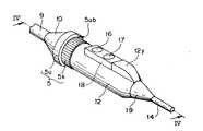
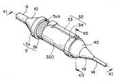
図1は、本発明の第1実施の形態を示す内視鏡装置の構成の概略を示す図、図2は、図1の撮像装置のカメラヘッドの拡大斜視図、図3は、図2のカメラヘッドに配設されたスライダが直線移動した状態を示すカメラヘッドの拡大斜視図である。(First embodiment)
FIG. 1 is a diagram showing an outline of the configuration of an endoscope apparatus showing a first embodiment of the present invention, FIG. 2 is an enlarged perspective view of a camera head of the imaging apparatus of FIG. 1, and FIG. FIG. 6 is an enlarged perspective view of the camera head showing a state in which a slider disposed on the camera head is linearly moved.
図1に示すように、内視鏡装置1は、体腔内や管路内等に挿入した際、被写体像が結像される図示しない対物レンズを有する内視鏡2と、内視鏡2の図示しない対物レンズに結像された被写体像を撮像する撮像装置4と、内視鏡2と撮像装置4を接続する光学アダプタ5と、周辺装置90とから主要部が構成されている。 As shown in FIG. 1, an endoscope apparatus 1 includes an
周辺装置90は、内視鏡2に照明光を供給する光源装置3と、撮像装置4において撮像された被写体像の撮像信号からモニタ表示ができるよう該撮像信号を映像信号に変換処理する、及び内視鏡2の動作制御を行う制御手段であるビデオプロセッサ6と、該ビデオプロセッサ6で変換された映像信号を映し出すモニタ装置7とから、主要部が構成されている。 The
内視鏡2は、体腔内や管路内等に挿入される細長の挿入部8と、該挿入部8の基端部に連設された本体部9と、該本体部9の一側面から延出し、端部が光源装置3に接続されて光源装置3からの照明光を内視鏡2に導光するライトガイドケーブル11と、内視鏡2の図示しない対物レンズに結像された被写体像を撮像装置4に出射する、本体部9の基端部に連設された接眼部10とを有して主要部が構成されている。尚、ライトガイドケーブル11の端部は、光源装置3に対して着脱自在である。 The
撮像装置4は、接眼部10の基端部に光学アダプタ5を介して接続されるカメラヘッド12と、接眼部10から出射される被写体像を撮像するカメラヘッド12に内蔵されたCCD等の撮像素子13と、該撮像素子13で撮像した被写体像の撮像信号等をビデオプロセッサ6へ伝送する、カメラヘッド12から折れ止め19(図2参照)を介して延出したケーブル14と、該ケーブル14をビデオプロセッサ6に接続する、該ケーブル14の端部に設けられたコネクタ15とを有して主要部が構成されている。 The imaging device 4 includes a
尚、接眼部10は、本体部9に対して着脱自在であり、コネクタ15は、ビデオプロセッサ6に対して着脱自在であり、さらには、光学アダプタ5も接眼部10に対して着脱自在である。 The
また、光学アダプタ5は、接眼部10が接続される受け部5uと、光学アダプタ5を接眼部10に対して着脱する際用いられる回転部5kを有して構成されており、回転部5kの後端に、カメラヘッド12が接続されている。尚、この接続により、カメラヘッド12は、内視鏡2を操作する際の該内視鏡2の手元側の操作部となる。 The
ビデオプロセッサ6に、該ビデオプロセッサ6で変換された被写体像の映像信号をモニタ装置7へ出力するモニタケーブル6aの一端が接続されている。モニタケーブル6aの他端は、モニタ装置7に接続されている。 One end of a monitor cable 6 a that outputs the video signal of the subject image converted by the
図2に示すように、カメラヘッド12は、カメラヘッドワク26(図4参照)から山部12yを有する略円筒状に形成されている。詳しくは、カメラヘッド12の図中上側のケーブル14側後半部に、カメラヘッドワク26から構成されたカメラヘッド12の主軸方向に略垂直な面(以下先端面と称す)12yzを有する山部12yが形成されている。 As shown in FIG. 2, the
カメラヘッド12の図中上側の円周面12aに、入力位置変更手段であるスライダ18が配設されている。スライダ18に、操作スイッチであるスイッチ16,17が配設されている。スイッチ16,17は、ビデオプロセッサ6に、該ビデオプロセッサ6において実行される映像信号の処理設定に関する信号を入力するスイッチ、言い換えれば映像信号処理等の動作指示を入力するプッシュスイッチである。 On the upper circumferential surface 12a of the
尚、各スイッチ16,17は、ビデオプロセッサ6によって、選択的に入力機能が割り当てられる。具体的には、例えば、スイッチ16には、撮像素子13で撮像され伝送された被写体像の映像信号に対してホワイトバランスに関する設定入力を行う機能が割り当てられており、スイッチ17には、撮像素子13で撮像され伝送された被写体像の映像信号の明るさを調節する入力を行う機能が割り当てられている。 The
スライダ18は、円周面12aにおいて、少なくとも2方向に移動するようになっている。詳しくは、後端面18bが、カメラヘッド12の山部12yの先端面12yzに当接している図2に示す位置から、後端面18bが先端面12yzから離間する位置、即ちスライダ18の先端面18fが光学アダプタの受け部5uの主軸方向に略垂直な面(以下後端面と称す)5ubに近接する図3に示す位置までスライド軸20によって、カメラヘッド12の主軸に沿って、円周面12aの上方を直線移動できるようになっている。 The
尚、図2に示す位置は、操作者がカメラヘッド12を親指以外の4本の指で把持すると、スイッチ16,17が操作者の手のひらの部分に配置されてしまう位置である。 The position shown in FIG. 2 is a position where the
次に、カメラヘッド12の内部の構成について説明する。図4は、図2中のIV−IV線に沿う断面図、図5は、図3中のV−V線に沿う断面図である。 Next, the internal configuration of the
カメラヘッド12は、カメラヘッドワク26から構成されており、カメラヘッドワク26の内部12iは中空となっている。内部12iに、CCD等の撮像素子13が配設されており、該撮像素子13に、他端がケーブル14の内部を通りビデオプロセッサ6と接続された信号ケーブル29の一端が複数接続されている。 The
スライダ18は、スイッチワク21と、カメラヘッド12の円周面12aに対向するソコイタ22とから構成されており、スイッチ16、17は、スイッチワク21に水密的に嵌合されている。 The
ソコイタ22上に、フレキシブル基板23が固定されており、フレキシブル基板23上のスイッチ16、17の接点部と一致する位置に、タクトスイッチ24、25がそれぞれ配置されている。 A
スイッチワク21とソコイタ22は、水密的に接合されている。スイッチワク21の後端面、即ちスライダ18の後端面18bに貫通孔が形成されており、該貫通孔に、スライド軸20の先端面が水密的に、嵌入され固定されている。 The
カメラヘッド12のカメラヘッドワク26の先端面12yzが形成された位置に、貫通孔が形成されており、該貫通孔に、中空状のスライド軸20が嵌入されている。スライド軸20はカメラヘッド12と主軸方向に対して2方向に摺動自在となっており、スライド軸20の外周とカメラヘッドワク26の貫通孔の内周との間に、スライド軸20とカメラヘッドワク26とを水密に保つOリング27が介装されている。 A through hole is formed at a position where the
このことにより、スライド軸20に接続されたスライダ18は、上述したように、後端面18bが、カメラヘッド12の山部12yの先端面12yzに当接している図2に示す位置から、後端面18bが先端面12yzから離間する位置、即ちスライダ18の先端面18fが光学アダプタの受け部5uの後端面5ubに近接する図3に示す位置までスライド軸20によってカメラヘッド12の主軸に沿って、円周面12aの上方を2方向に直線移動できるようになっている。 As a result, the
スライド軸20の中空状に形成された内部20iに、一端がタクトスイッチ24、25と電気的に接続され、他端がケーブル14の内部を通りビデオプロセッサ6と接続されている、柔軟性を有するスイッチケーブル28が配設されている。 One end is electrically connected to the tact switches 24 and 25 and the other end is connected to the
次に、このように構成された本実施の形態における内視鏡装置1の作用について説明する。 Next, the operation of the endoscope apparatus 1 according to the present embodiment configured as described above will be described.
まず、操作者によるビデオプロセッサ6の操作によって、例えば、スイッチ16には、撮像素子13で撮像され伝送された被写体像の映像信号に対してホワイトバランスに関する設定入力を行う機能が割り当てられ、スイッチ17には、撮像素子13で撮像され伝送された被写体像の映像信号の明るさを入力によって調節する機能が割り当てられる。 First, by the operation of the
よって、スライダ18の後端面18bが、カメラヘッド12の山部12yの先端面12yzに当接している図4の位置にあるとき、スイッチ16が押圧されると、撮像素子13で撮像され伝送された被写体像の映像信号に対してホワイトバランスに関する設定ができ、また、スイッチ17が押圧されると、撮像素子13で撮像され伝送された被写体像の映像信号に対して明るさを調節することができる。 Therefore, when the
次に、スライダ18が、スライド軸20によってスライドされ図4に示す位置から、スライダ18の先端面18fが光学アダプタの受け部5uの後端面5ubに近接する図5に示す位置までカメラヘッド12の主軸に沿って、円周面12aの上方を直線移動したときは、スライダ18の移動に伴い、スイッチ16、17、タクトスイッチ24、25、フレキシブル基板23も主軸に沿って直線移動する。 Next, the
その際、スイッチケーブル28は柔軟性を有しているため、タクトスイッチ24、25と、ビデオプロセッサ6との電気的接続は保たれたままである。よって、図3、図5に示す位置に、スライダ18が移動された際、スイッチ16が押圧されると、図2、図4での位置同様、撮像素子13で撮像され伝送された被写体像の映像信号に対してホワイトバランスに関する設定ができ、また、スイッチ17が押圧されると、撮像素子13で撮像され伝送された被写体像の映像信号に対して明るさを調節することができる。 At this time, since the
このように、本発明の第1実施の形態を示す内視鏡装置1においては、内視鏡装置1の内視鏡2の後端部に接続された撮像装置4の手元側操作部であるカメラヘッド12に配設されたスイッチ16,17が設けられたスライダ18が、図2,図4に示す位置から、図3,図5に示す位置までスライド軸20によりカメラヘッド12の主軸に沿って、円周面12aの上方を直線移動できるようにし、さらには、スライダ18の移動にかかわらず、スイッチ16,17によってビデオプロセッサ6に対する入力が行えるようにした。 Thus, in the endoscope apparatus 1 which shows 1st Embodiment of this invention, it is a hand side operation part of the imaging device 4 connected to the rear-end part of the
このことにより、図2,図4に示す位置においては、操作者がカメラヘッド12を親指以外の4本の指で把持すると、スイッチ16,17が操作者の手のひらの部分に配置されてしまうが、スライダ18を、図3,図5に示す位置に移動させれば、操作者は容易に、手の親指を用いてスイッチ16,17を操作することができる。 2 and 4, when the operator holds the
また、このことに限らず、スライダを、図2、図4〜図3、図5の間であれば自由に2方向に直線移動させることができることから、操作者の使い方、握り方に応じて操作しやすい位置に、スイッチ16,17を配置することができるため、操作性に優れたスイッチ16,17が配設された内視鏡装置1を提供することができる。 In addition to this, the slider can be freely linearly moved in two directions as long as it is between FIG. 2, FIG. 4 to FIG. 3, and FIG. Since the
また、図3、図5に示す位置に、スライダ18が配置されてもOリング27によりカメラヘッドワク26内に消毒液等が浸入しないようになっている。よって、内視鏡2を体腔内に挿入させ各種観察等を行っている最中に、スライダ18を図3、図5に示す位置にスライドさせても、カメラヘッドワク26内への消毒液等の侵入を防ぐことができる。よって、スライダ18をどの位置に配置していても、消毒滅菌を行うことができる。よって、水密性、耐消毒滅菌性といった従来の機能を維持したまま、スイッチ16,17の位置を変更することができる。 Further, even when the
以下、変形例を示す。本実施の形態においては、ビデオプロセッサ6により、スイッチ16には、撮像素子13で撮像され伝送された被写体像の映像信号に対してホワイトバランスに関する設定入力を行う機能が割り当てられており、スイッチ17には、撮像素子13で撮像され伝送された被写体像の映像信号の明るさ入力により調節する機能が割り当てられていると示した。 Hereinafter, a modification is shown. In the present embodiment, the
これに限らず、スイッチ16,17に、他の映像信号処理等の動作指示を入力する機能を割り当てても良く、また、撮像装置4を用いて撮像動作を行う際、内視鏡2に対して各種操作を入力するためのスイッチ、例えばレリーズスイッチや、アングル調整スイッチを割り当てても良い。 However, the present invention is not limited to this, and a function for inputting operation instructions such as other video signal processing may be assigned to the
また、スライダ18に配設されるスイッチは、本実施の形態においては、2つのスイッチを例に挙げて示したが、これに限らず、可能な限りいくつ配設しても良いということは勿論である。 Further, in the present embodiment, two switches are shown as examples of the switches disposed on the
さらに、スライダ18は、図2に示す位置と、図3に示す位置との少なくとの2方向に直線移動すると示したが、これに限らず、複数の方向に移動できるようにしても、本実施の形態と同様の効果を得ることができる。 Furthermore, although the
また、本実施の形態においては、医療用具は、接眼部10を備え、撮像装置が接続される内視鏡を例に挙げて示したが、これに限らず、撮像装置が内視鏡に内蔵されたタイプの内視鏡の操作部に、スイッチ16,17が設けられたスライダ18を配設しても、または医療用処置具の把持部に、スイッチ16,17が設けられたスライダ18を配設しても本実施の形態と同様の効果を得ることができる。尚、この場合、処置具が例えば電気メスであれば、スイッチ16,17は、刃部に通電を開始させるためのものであってもよい。 In the present embodiment, the medical device includes an
これに伴い、医療用装置は内視鏡を備えた内視鏡装置を例に挙げて示したが、これに限らず、処置具を備えた装置であっても良い。 Along with this, the medical apparatus has been described by taking an endoscope apparatus including an endoscope as an example, but is not limited thereto, and may be an apparatus including a treatment tool.
(第2実施の形態)
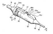
図6は、本発明の第2実施の形態を示す内視鏡装置の撮像装置のカメラヘッドの断面図、図7は、図6のカメラヘッドに配設されたスライダが直線移動した状態を示すカメラヘッドの断面図、図8は、図6のカメラヘッドに配設されたスライダに設けられたスイッチの機能を示した図表である。(Second Embodiment)
FIG. 6 is a cross-sectional view of a camera head of an imaging apparatus of an endoscope apparatus showing a second embodiment of the present invention, and FIG. 7 shows a state in which a slider arranged in the camera head of FIG. FIG. 8 is a table showing the function of a switch provided on a slider provided in the camera head of FIG.
この第2実施の形態の内視鏡装置の構成は、上記図1乃至図5に示した内視鏡装置1と比して、カメラヘッド内に、検知スイッチが配設されている点のみが異なる。よって、この相違点のみを説明し、第1実施の形態と同様の構成には同じ符号を付し、その説明は省略する。 The configuration of the endoscope apparatus according to the second embodiment is only that a detection switch is provided in the camera head as compared with the endoscope apparatus 1 shown in FIGS. Different. Therefore, only this difference will be described, the same reference numerals are given to the same components as those in the first embodiment, and the description thereof will be omitted.
図6、図7に示すように、内視鏡装置201の手元側操作部であるカメラヘッド220の内部220iであって、山部220yの先端面220yzを構成するカメラヘッドワク26におけるスライド軸20の近傍に、例えばプッシュスイッチから構成された検知スイッチ30が配設されている。検知スイッチ30は、後述するが、スライダ18の少なくとも2方向の直線移動によってオンオフされる。尚、検知スイッチ30は、非接触式であってもよい。 As shown in FIGS. 6 and 7, the
また、スライド軸20の後端部に、検知スイッチ30に接触する高さを有するフランジ部20aが設けられている。尚、スライド軸20のフランジ部20a以外の外周は、検知スイッチ30とは非接触となっている。 Further, a
検知スイッチ30と、検知スイッチケーブル31の一端は電気的に接続されており、検知スイッチケーブル31の他端は、ケーブル14の内部を通ってビデオプロセッサ6と接続されている。 One end of the
次に、このように構成された本実施の形態における内視鏡装置201の作用について説明する。 Next, the operation of the
スライダ18が、図6に示す位置、即ち、スライダ18の後端面18bが、カメラヘッド220の山部220yの先端面220yzに当接しているときには、スライド軸20のフランジ部20aは、プッシュスイッチである検知スイッチ30から離間されている。即ち、フランジ部20aと検知スイッチ30は、非接触である。このことにより、検知スイッチ30は、ビデオプロセッサ6に検知スイッチケーブル31を介してオフを出力する。即ち、検知スイッチ30はオフである。 When the
このとき、ビデオプロセッサ6により、スイッチ16、17には、図8に示すように、それぞれ1つずつ選択的に入力機能が割り当てられており、例えば、スイッチ16には、撮像素子13で撮像され伝送された被写体像の映像信号に対してホワイトバランスに関する設定入力を行う機能が割り当てられており、スイッチ17には、撮像素子13で撮像され伝送された被写体像の映像信号の明るさを入力により調節する機能が割り当てられている。 At this time, the
次に、スライダ18が、図6に示す位置から、スライダ18の先端面18fが光学アダプタの受け部5uの後端面5ubに近接する図7に示す位置までカメラヘッド220の主軸に沿って、上面220aの上方を直線移動したときは、スライド軸20のフランジ部20aが検知スイッチ30に接触する。このことにより、検知スイッチ30は、ビデオプロセッサ6に検知スイッチケーブル31を介してオンを出力する。即ち、検知スイッチ30はオンである。 Next, the upper surface of the
検知スイッチ30がオンのときには、スイッチ16、17は、検知スイッチ30がオフのときに割り当てた機能とは別の機能、例えば映像信号の処理設定に関する信号の入力のみならず、内視鏡2の操作に関する信号の入力機能を割り当てることができる。 When the
例えば、検知スイッチ30がオンのときは、図8に示すように、スイッチ16には、撮像素子13で撮像され伝送された被写体像の静止画をモニタ装置7に表示させるフリーズ機能が割り当てられ、スイッチ17には、撮像素子13で撮像され伝送された被写体像を記録媒体に記録する機能、即ちレリーズ機能等が割り当てられている。 For example, when the
このように、本発明の第2実施の形態を示す内視鏡装置201においては、カメラヘッド220の内部220iに、スライド軸20の後端部に設けられたフランジ部20aを検知する、即ちスライダ18の移動を検知する検知スイッチ30を設けた。 Thus, in the
このことにより、2つのスイッチ16、17が設けられたスライダ18を、図6に示す位置と図7に示す位置とに2方向に直線移動させることで、スイッチの個数を4つに増やすことなく、2つのスイッチ16,17に4つの入力機能を割り当てることができる。 Accordingly, the
また、スライダ18の図6に示す位置は、操作者がカメラヘッド220を親指以外の4本の指で把持すると、スイッチ16,17が操作者の手のひらの部分に配置されてしまい、スイッチ操作が親指でし難い位置である。 Further, the position of the
よって、スライダ18が図6の位置にあるときには、内視鏡2を操作する前に設定する機能、あるいは操作中に内視鏡2またはカメラヘッド220がぶれても特に影響のない機能を割り当てればよい。例えば本実施の形態においては、図8に示すように、ホワイトバランスに関する設定を行う機能と明るさを調整する機能とを割り当てた。 Therefore, when the
スライダ18を図6に示す位置から直線移動させて、図7に示す位置に移動させた場合、スライダ18の図7に示す位置においては、操作者は容易に、親指を用いてスイッチ16,17を操作することができる。 When the
よって、スライダ18が図7の位置にあるときは、内視鏡2を操作している最中に操作する機能、内視鏡2を操作している最中に内視鏡またはカメラヘッド220がぶれると困る機能を割り当てればよい。例えば、本実施の形態においては、図8に示すように、静止画を表示させるフリーズ機能と内視鏡画像を記録媒体に記録するレリーズ機能とを割り当てた。 Therefore, when the
このことにより、カメラヘッド220を大型化することなく、限られた数のスイッチにより多くの機能を割り当てることができる、及びスイッチの位置によって適した機能を割り当てることができる内視鏡装置201を提供することができる。 As a result, an
尚、その他の効果は、上述した第1実施の形態の内視鏡装置1と同様である。 Other effects are the same as those of the endoscope apparatus 1 according to the first embodiment described above.
以下、変形例を示す。 Hereinafter, a modification is shown.
本実施の形態においては、ビデオプロセッサ6により、スライダ18が、図6の位置にあるときは、スイッチ16には、ホワイトバランスに関する設定入力を行う機能が割り当てられており、スイッチ17には、映像信号の明るさを調節する機能が割り当てられていると示した。また、スライダ18が、図7に示す位置に移動された場合は、スイッチに16には、静止画を表示させるフリーズ機能、スイッチ17には、内視鏡画像を記録媒体に記録するレリーズ機能が割り当てられていると示した。 In the present embodiment, when the
これに限らず、スライダ18の移動に応じて、言い換えれば検知スイッチ30のオンオフに応じて割り当てられる、スイッチ16,17の4つの機能には、他の映像信号処理等の動作指示を入力する機能を割り当てても良く、また、撮像装置4を用いて内視鏡2を介して撮像動作を行う際、各種操作を入力するためのスイッチ機能、例えばレリーズスイッチや、アングル調整スイッチ機能を割り当てても良い。即ち、どんな入力機能を割り当てても良い。 Not limited to this, the four functions of the
また、スライダ18に配設されるスイッチは、本実施の形態においては、2つのスイッチを例に挙げて示したが、これに限らず、可能な限りいくつ配設しても良いということは勿論である。 Further, in the present embodiment, two switches are shown as examples of the switches disposed on the
さらに、スライダ18は、図6に示す位置と、図7に示す位置との少なくとの2方向に直線移動すると示したが、これに限らず、複数の方向に移動できるようにしても、本実施の形態と同様の効果を得ることができる。 Further, the
さらに、検知スイッチ30は、カメラヘッド220に、1つのみ配設する例を挙げて示したが、これに限らず、可能な限りいくつ配設してもよい。このことにより、スイッチ16,17に、4つに限らず複数の機能を割り当てることができる。例えば、検知スイッチ30を2つ配設すれば、スイッチ16,17に6つの入力機能を割り当てることができる。 Furthermore, although the example which arrange | positions only one
尚、本実施の形態においても、医療用具は、接眼部10を備え、撮像装置が接続される内視鏡を例に挙げて示したが、これに限らず、撮像装置が内視鏡に内蔵されたタイプの内視鏡の操作部にスイッチ16,17が設けられたスライダ18を配設しても、または医療用処置具の把持部に、スイッチ16,17が設けられたスライダ18を配設しても本実施の形態と同様の効果を得ることができる。尚、この場合、処置具が例えば電気メスであれば、スイッチ16,17は、刃部に通電を開始させるためのものであってもよい。これに伴い、医療用装置は内視鏡を備えた内視鏡装置を例に挙げて示したが、これに限らず、処置具を備えた装置であっても良い。 Also in the present embodiment, the medical device includes the
(第3実施の形態)
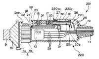
図9は、本発明の第3実施の形態を示す内視鏡装置のカメラヘッドを示す斜視図、図10は、図9のカメラヘッドに配設された回動部材が回動した状態を示すカメラヘッドの斜視図、図11は、図10中のXI−XI線に沿う断面図、図12は、図10中のXII−XII線に沿う断面図、図13は、図9中のXIII−XIII線に沿う断面図、図14は、図9のカメラヘッドに配設されたスイッチの機能を示した図表である。(Third embodiment)
FIG. 9 is a perspective view showing a camera head of an endoscope apparatus showing a third embodiment of the present invention, and FIG. 10 shows a state in which a turning member arranged in the camera head of FIG. 9 is turned. 11 is a cross-sectional view taken along line XI-XI in FIG. 10, FIG. 12 is a cross-sectional view taken along line XII-XII in FIG. 10, and FIG. 13 is taken along line XIII- in FIG. FIG. 14 is a cross-sectional view taken along line XIII, and FIG. 14 is a table showing the functions of the switches arranged in the camera head of FIG.
この第3実施の形態の内視鏡装置の構成は、上記図6、図7に示した内視鏡装置201と比して、操作スイッチは移動せずに、該1つの操作スイッチに複数の機能を割り当てることができる点のみが異なる。よって、この相違点のみを説明し、第1,第2実施の形態と同様の構成には同じ符号を付し、その説明は省略する。 Compared with the
図9、図10に示すように、内視鏡装置301の手元側の操作部であるカメラヘッド320に、入力位置変更手段である操作レバーユニット32が、内視鏡2の主軸方向を中心に少なくとも2方向に回動自在となるよう配設されている。操作レバーユニット32は、操作レバー33と、回転リング34とから主要部が構成されている。 As shown in FIGS. 9 and 10, an
図11に示すように、カメラヘッド320は、カメラヘッドワク35によって構成されており、カメラヘッドワク35に、接触面が図中上方に露出するよう、操作スイッチであるスイッチ36が水密的に嵌合固定されている。 As shown in FIG. 11, the
スイッチ36は、ビデオプロセッサ6に、該ビデオプロセッサ6において実行される映像信号の処理設定に関する信号を入力するスイッチ、言い換えれば映像信号処理等の動作指示を入力するプッシュスイッチである。 The
カメラヘッドワク35に覆われたカメラヘッド320の内部320iに、リジッド基板37がカメラヘッドワク35に固定されて配設されており、リジッド基板37上であって、スイッチ36の接点部と一致する位置に、タクトスイッチ38が配設されている。 A
タクトスイッチ38は、スイッチ36の接点部によってオンオフされるプッシュスイッチであり、一端がケーブル14を介してビデオプロセッサ6と接続されたスイッチケーブル28の他端が電気的に接続されることにより、ビデオプロセッサ6と接続されている。 The
回転リング34は、カメラヘッドワク35の外周に、2つのOリング39を介して水密的かつ2方向に回動自在に配設されている。カメラヘッドワク35の、2つのOリング39の間の位置に、検知スイッチ40が嵌合固定されている。検知スイッチ40は、一端がケーブル14を介してビデオプロセッサ6と接続された検知スイッチケーブル41の他端が電気的に接続されることにより、ビデオプロセッサ6と接続されている。 The rotating
回転リング34に、図11中上方に突出する凹状の突出部34aが設けられており、該突出部34aは、操作レバー33に形成された貫通孔に嵌合され、固定ピン43が、突出部34aの穴部に嵌入されることにより、操作レバー33に固定されている。また、突出部34aと操作レバー33との間に、板バネ42が嵌合されている。 The rotating
よって、回転リング34は、例えば図12に示す位置から図13に示す位置に回転された後、操作者が操作レバー33から手を放したとしても、板バネ42の弾性力により、図12の位置に戻るようになっている。 Therefore, for example, even if the operator releases the
また、図12、図13に示すように、回転リング34の内周面に、図12の位置において検知スイッチ40に接触する高さを有する突起部34bが設けられている。尚、突起部34bの突起部34b以外の内周面は、検知スイッチ40と非接触となっている。 As shown in FIGS. 12 and 13, a
操作レバー33の下面であって、スイッチ36と対向する位置に、スイッチ36を押圧する押しピン44が固定されている。カメラヘッドワク35の後端部に、ウシロカバー45が水密的に接合されている。ウシロカバー45の内部に、オレドメ19、ケーブル14が嵌入され固定されている。 A
次に、このように構成された本実施の形態における内視鏡装置301の作用について説明する。 Next, the operation of the
操作レバーユニット32が図10に示す位置にあるとき、図12に示すように、回転リング34の突起部34bは、検知スイッチ40と接触する。この際、検知スイッチ40は、ビデオプロセッサ6に検知スイッチケーブル41を介してオンを出力する。即ち、検知スイッチ40はオンになる。このとき、操作者は、操作レバーユニット32の操作レバー33を用いてスイッチ36を用いた入力を行うことができる。 When the
操作レバーユニット32が図10に示す位置から、回転リング34を介してカメラヘッド320の外周上を回動して図9に示す位置に移動したとき、図13に示すように、突起部34bは、検知スイッチ40から離間する。即ち、突起部34bと検知スイッチ40とは非接触となる。この際、検知スイッチ40は、ビデオプロセッサ6に検知スイッチケーブル41を介してオフを出力する。即ち、検知スイッチ40はオフになる。このとき、操作者は、該操作者の指によってスイッチ36を用いた入力を行うことができる。 When the
尚、スイッチ36は、検知スイッチ40がオンオフされることにより、ビデオプロセッサ6によって、選択的に入力機能が割り当てられる。具体的には、図14に示すように、例えば、図9、図13に示す位置に、操作レバーユニット32があるときは、即ち検知スイッチ40がオフのときは、スイッチ36には、撮像素子13で撮像され伝送された被写体像の映像信号に対してホワイトバランスに関する設定入力を行う機能が割り当てられている。よって、操作者は、スイッチ36を押下すると、ホワイトバランスの入力を行うことができる。 The
操作レバーユニット32が図9に示す位置から、回転リング34を介してカメラヘッド320の外周上を回動して図10、図12に示す位置に移動したときは、即ち検知スイッチ40がオンのときには、スイッチ36には、撮像素子13で撮像され伝送された被写体像の静止画をモニタ装置7に表示させるフリーズ機能が割り当てられている。よって、操作者は、操作レバーユニット32の操作レバー33を用いてスイッチ36を押下すると、モニタ装置7に静止画を表示させることができる。 When the
このように、本発明の第3実施の形態を示す内視鏡装置301においては、カメラヘッド320の内部320iに、カメラヘッド320の外周に2方向に回動移動する回転リング34の突起部34bを検知する、即ち回転リング34に固定された操作レバー33の回動移動を検知する検知スイッチ40を設けた。また、スイッチ36をカメラヘッド320に固定した。 As described above, in the
このことにより、回転リング34を、図9に示す位置と図10に示す位置とに2方向に回動移動させることで、スイッチ36を移動することなく、またスイッチの個数を2つに増やすことなく、1つの固定されたスイッチ36に2つの入力機能を割り当てることができる。 As a result, the
このことにより、カメラヘッド320を大型化することなく、限られた数のスイッチにより多くの機能を割り当てることができる、及びスイッチの位置によって適した機能を割り当てることができる内視鏡装置301を提供することができる。 This provides an
以下、変形例を示す。 Hereinafter, a modification is shown.
本実施の形態においては、回転リング34が、図9の位置にあるときは、ビデオプロセッサ6により、スイッチ36には、ホワイトバランスに関する設定入力を行う機能が割り当てられており、回転リング34が、図8に示す位置に移動された場合は、スイッチに16には、静止画を表示させるフリーズ機能が割り当てられていると示した。 In the present embodiment, when the
これに限らず、回転リング34の移動に応じて、言い換えれば検知スイッチ40のオンオフに応じて割り当てられる、スイッチ36の2つの機能には、他の映像信号処理等の動作指示を入力する機能を割り当てても良く、また、撮像装置4を用いて内視鏡2を介して撮像動作を行う際、各種操作を入力するためのスイッチ機能、例えばレリーズスイッチや、アングル調整スイッチ機能を割り当てても良い。即ち、どんな入力機能を割り当てても良い。 Not limited to this, the two functions of the
また、スイッチ36は、本実施の形態においては、1つのスイッチを例に挙げて示したが、これに限らず、可能な限りいくつ配設しても良いということは勿論である。 Further, in the present embodiment, the
さらに、回転リング34は、少なくとも2方向に回動すると示したが、これに限らず、複数の方向に回動しても本実施の形態と同様の効果を得ることができるということは勿論である。 Furthermore, although it has been shown that the
尚、本実施の形態においても、医療用具は、接眼部10を備え、撮像装置が接続される内視鏡を例に挙げて示したが、これに限らず、撮像装置が内視鏡に内蔵されたタイプの内視鏡の操作部にスイッチ36を配設しても、または医療用処置具の把持部に、スイッチ36を配設しても本実施の形態と同様の効果を得ることができる。尚、この場合、処置具が例えば電気メスであれば、スイッチ36は、刃部に通電を開始させるためのものであってもよい。これに伴い、医療用装置は内視鏡を備えた内視鏡装置を例に挙げて示したが、これに限らず、処置具を備えた装置であっても良い。 Also in the present embodiment, the medical device includes the
[付記]
以上詳述した如く、本発明の実施形態によれば、以下の如き構成を得ることができる。即ち、
(1)
手元側に操作部を有する医療用具を備える医療用装置であって、
上記医療用具の上記操作部に、操作スイッチと、上記操作部に対して少なくとも2方向に回動移動する入力位置変更手段と、上記入力位置変更手段の回動移動によってオンオフされる検知スイッチとが設けられおり、
上記医療用具に、該医療用具の動作制御及び該医療用具を介して撮像された映像信号の処理を行う制御手段が設けられており、
上記検知スイッチのオンオフに応じて、上記操作スイッチに、上記制御手段に入力する上記医療用処置具の操作に関する信号と上記映像信号の処理設定に関する信号との少なくとも一方の信号が割り当てられていることを特徴とする医療用装置。[Appendix]
As described in detail above, according to the embodiment of the present invention, the following configuration can be obtained. That is,
(1)
A medical device provided with a medical tool having an operation part on the hand side,
The operation unit of the medical device includes an operation switch, an input position changing unit that rotates and moves in at least two directions with respect to the operation unit, and a detection switch that is turned on and off by the rotation of the input position changing unit. Provided,
The medical device is provided with control means for performing operation control of the medical device and processing of a video signal imaged through the medical device,
According to the on / off state of the detection switch, at least one of the signal related to the operation of the medical treatment instrument and the signal related to the processing setting of the video signal input to the control means is assigned to the operation switch. A medical device characterized by.
1…内視鏡装置
2…内視鏡
12…カメラヘッド
16…操作スイッチ
17…操作スイッチ
18…スライダ
32…操作レバーユニット
33…操作レバー
36…操作スイッチ
201…内視鏡装置
220…カメラヘッド
301…内視鏡装置
320…カメラヘッド
代理人 弁理士 伊藤 進DESCRIPTION OF SYMBOLS 1 ...
Claims (6)
Translated fromJapanese上記操作部に、操作スイッチが設けられており、
上記操作スイッチは、上記操作部において少なくとも2方向に移動する入力位置変更手段に配設されていることを特徴とする医療用装置。A medical device provided with a medical tool having an operation part on the hand side,
The operation unit is provided with an operation switch,
The medical device according to claim 1, wherein the operation switch is disposed in an input position changing unit that moves in at least two directions in the operation unit.
上記操作スイッチは、上記制御手段に、上記内視鏡の操作に関する信号と上記映像信号の処理設定に関する信号との少なくとも一方の信号を入力するスイッチであることを特徴とする請求項2に記載の医療用装置。A control means for performing operation control of the endoscope and processing of a video signal imaged through the endoscope;
3. The switch according to claim 2, wherein the operation switch is a switch for inputting at least one of a signal related to the operation of the endoscope and a signal related to the processing setting of the video signal to the control unit. Medical device.
Priority Applications (1)
| Application Number | Priority Date | Filing Date | Title |
|---|---|---|---|
| JP2004198529AJP2006015078A (en) | 2004-07-05 | 2004-07-05 | Medical apparatus |
Applications Claiming Priority (1)
| Application Number | Priority Date | Filing Date | Title |
|---|---|---|---|
| JP2004198529AJP2006015078A (en) | 2004-07-05 | 2004-07-05 | Medical apparatus |
Publications (1)
| Publication Number | Publication Date |
|---|---|
| JP2006015078Atrue JP2006015078A (en) | 2006-01-19 |
Family
ID=35789822
Family Applications (1)
| Application Number | Title | Priority Date | Filing Date |
|---|---|---|---|
| JP2004198529AWithdrawnJP2006015078A (en) | 2004-07-05 | 2004-07-05 | Medical apparatus |
Country Status (1)
| Country | Link |
|---|---|
| JP (1) | JP2006015078A (en) |
Cited By (177)
| Publication number | Priority date | Publication date | Assignee | Title |
|---|---|---|---|---|
| JP2007296369A (en)* | 2006-05-04 | 2007-11-15 | Sherwood Services Ag | Open vessel sealing forceps disposable handswitch |
| EP2123209A1 (en) | 2008-05-21 | 2009-11-25 | Olympus Medical Systems Corporation | Electronic endoscope apparatus |
| US8523898B2 (en) | 2009-07-08 | 2013-09-03 | Covidien Lp | Endoscopic electrosurgical jaws with offset knife |
| US8540712B2 (en) | 2010-08-20 | 2013-09-24 | Covidien Lp | Surgical instrument configured for use with interchangeable hand grips |
| US8568444B2 (en) | 2008-10-03 | 2013-10-29 | Covidien Lp | Method of transferring rotational motion in an articulating surgical instrument |
| US8574230B2 (en) | 2009-09-03 | 2013-11-05 | Covidien Lp | Open vessel sealing instrument with pivot assembly |
| US8591506B2 (en) | 1998-10-23 | 2013-11-26 | Covidien Ag | Vessel sealing system |
| US8597296B2 (en) | 2003-11-17 | 2013-12-03 | Covidien Ag | Bipolar forceps having monopolar extension |
| US8679140B2 (en) | 2012-05-30 | 2014-03-25 | Covidien Lp | Surgical clamping device with ratcheting grip lock |
| US8747434B2 (en) | 2012-02-20 | 2014-06-10 | Covidien Lp | Knife deployment mechanisms for surgical forceps |
| US8764749B2 (en) | 2008-04-22 | 2014-07-01 | Covidien | Jaw closure detection system |
| US8864753B2 (en) | 2011-12-13 | 2014-10-21 | Covidien Lp | Surgical Forceps Connected to Treatment Light Source |
| US8887373B2 (en) | 2012-02-24 | 2014-11-18 | Covidien Lp | Vessel sealing instrument with reduced thermal spread and method of manufacture therefor |
| US8920461B2 (en) | 2012-05-01 | 2014-12-30 | Covidien Lp | Surgical forceps with bifurcated flanged jaw components |
| US8939975B2 (en) | 2012-07-17 | 2015-01-27 | Covidien Lp | Gap control via overmold teeth and hard stops |
| US8968313B2 (en) | 2012-06-12 | 2015-03-03 | Covidien Lp | Electrosurgical instrument with a knife blade stop |
| US8968311B2 (en) | 2012-05-01 | 2015-03-03 | Covidien Lp | Surgical instrument with stamped double-flag jaws and actuation mechanism |
| US8968306B2 (en) | 2011-08-09 | 2015-03-03 | Covidien Lp | Surgical forceps |
| US8968309B2 (en) | 2011-11-10 | 2015-03-03 | Covidien Lp | Surgical forceps |
| USD726910S1 (en) | 2013-08-07 | 2015-04-14 | Covidien Lp | Reusable forceps for open vessel sealer with mechanical cutter |
| US9011436B2 (en) | 2012-06-26 | 2015-04-21 | Covidien Lp | Double-length jaw system for electrosurgical instrument |
| US9011435B2 (en) | 2012-02-24 | 2015-04-21 | Covidien Lp | Method for manufacturing vessel sealing instrument with reduced thermal spread |
| USD728786S1 (en) | 2013-05-03 | 2015-05-05 | Covidien Lp | Vessel sealer with mechanical cutter and pistol-grip-style trigger |
| US9024237B2 (en) | 2009-09-29 | 2015-05-05 | Covidien Lp | Material fusing apparatus, system and method of use |
| US9034009B2 (en) | 2012-05-01 | 2015-05-19 | Covidien Lp | Surgical forceps |
| US9033981B2 (en) | 2008-12-10 | 2015-05-19 | Covidien Lp | Vessel sealer and divider |
| US9039691B2 (en) | 2012-06-29 | 2015-05-26 | Covidien Lp | Surgical forceps |
| US9039731B2 (en) | 2012-05-08 | 2015-05-26 | Covidien Lp | Surgical forceps including blade safety mechanism |
| US9060780B2 (en) | 2011-09-29 | 2015-06-23 | Covidien Lp | Methods of manufacturing shafts for surgical instruments |
| US9072524B2 (en) | 2012-06-29 | 2015-07-07 | Covidien Lp | Surgical forceps |
| USD736920S1 (en) | 2013-08-07 | 2015-08-18 | Covidien Lp | Open vessel sealer with mechanical cutter |
| US9113903B2 (en) | 2006-01-24 | 2015-08-25 | Covidien Lp | Endoscopic vessel sealer and divider for large tissue structures |
| US9113901B2 (en) | 2012-05-14 | 2015-08-25 | Covidien Lp | Modular surgical instrument with contained electrical or mechanical systems |
| US9113905B2 (en) | 2008-07-21 | 2015-08-25 | Covidien Lp | Variable resistor jaw |
| US9113897B2 (en) | 2012-01-23 | 2015-08-25 | Covidien Lp | Partitioned surgical instrument |
| US9113940B2 (en) | 2011-01-14 | 2015-08-25 | Covidien Lp | Trigger lockout and kickback mechanism for surgical instruments |
| US9113906B2 (en) | 2010-01-22 | 2015-08-25 | Covidien Lp | Compact jaw including split pivot pin |
| US9113941B2 (en) | 2009-08-27 | 2015-08-25 | Covidien Lp | Vessel sealer and divider with knife lockout |
| US9168052B2 (en) | 2010-06-02 | 2015-10-27 | Covidien Lp | Apparatus for performing an electrosurgical procedure |
| US9192432B2 (en) | 2012-05-29 | 2015-11-24 | Covidien Lp | Lever latch assemblies for surgical improvements |
| US9192421B2 (en) | 2012-07-24 | 2015-11-24 | Covidien Lp | Blade lockout mechanism for surgical forceps |
| US9192433B2 (en) | 2010-06-02 | 2015-11-24 | Covidien Lp | Apparatus for performing an electrosurgical procedure |
| USD744644S1 (en) | 2013-08-07 | 2015-12-01 | Covidien Lp | Disposable housing for open vessel sealer with mechanical cutter |
| US9204924B2 (en) | 2006-10-06 | 2015-12-08 | Covidien Lp | Endoscopic vessel sealer and divider having a flexible articulating shaft |
| US9259266B2 (en) | 2008-02-15 | 2016-02-16 | Covidien Lp | Method and system for sterilizing an electrosurgical instrument |
| US9301798B2 (en) | 2012-07-19 | 2016-04-05 | Covidien Lp | Surgical forceps including reposable end effector assemblies |
| US9318691B2 (en) | 2010-04-29 | 2016-04-19 | Covidien Lp | Method of constructing a jaw member for an end effector assembly |
| US9375258B2 (en) | 2012-05-08 | 2016-06-28 | Covidien Lp | Surgical forceps |
| US9375259B2 (en) | 2012-10-24 | 2016-06-28 | Covidien Lp | Electrosurgical instrument including an adhesive applicator assembly |
| US9375256B2 (en) | 2013-02-05 | 2016-06-28 | Covidien Lp | Electrosurgical forceps |
| US9375262B2 (en) | 2013-02-27 | 2016-06-28 | Covidien Lp | Limited use medical devices |
| US9375260B2 (en) | 2010-04-12 | 2016-06-28 | Covidien Lp | Surgical instrument with non-contact electrical coupling |
| US9375205B2 (en) | 2012-11-15 | 2016-06-28 | Covidien Lp | Deployment mechanisms for surgical instruments |
| US9375267B2 (en) | 2010-06-02 | 2016-06-28 | Covidien Lp | Apparatus for performing an electrosurgical procedure |
| US9433461B2 (en) | 2012-09-07 | 2016-09-06 | Covidien Lp | Instruments, systems, and methods for sealing tissue structures |
| US9439711B2 (en) | 2012-10-02 | 2016-09-13 | Covidien Lp | Medical devices for thermally treating tissue |
| US9439717B2 (en) | 2013-08-13 | 2016-09-13 | Covidien Lp | Surgical forceps including thermal spread control |
| US9445865B2 (en) | 2013-09-16 | 2016-09-20 | Covidien Lp | Electrosurgical instrument with end-effector assembly including electrically-conductive, tissue-engaging surfaces and switchable bipolar electrodes |
| US9456863B2 (en) | 2013-03-11 | 2016-10-04 | Covidien Lp | Surgical instrument with switch activation control |
| US9468453B2 (en) | 2013-05-03 | 2016-10-18 | Covidien Lp | Endoscopic surgical forceps |
| US9492223B2 (en) | 2010-06-02 | 2016-11-15 | Covidien Lp | Apparatus for performing an electrosurgical procedure |
| US9498281B2 (en) | 2012-11-27 | 2016-11-22 | Covidien Lp | Surgical apparatus |
| US9510891B2 (en) | 2012-06-26 | 2016-12-06 | Covidien Lp | Surgical instruments with structures to provide access for cleaning |
| US9526567B2 (en) | 2011-05-16 | 2016-12-27 | Covidien Lp | Thread-like knife for tissue cutting |
| US9526564B2 (en) | 2012-10-08 | 2016-12-27 | Covidien Lp | Electric stapler device |
| US9545262B2 (en) | 2010-06-02 | 2017-01-17 | Covidien Lp | Apparatus for performing an electrosurgical procedure |
| US9549749B2 (en) | 2012-10-08 | 2017-01-24 | Covidien Lp | Surgical forceps |
| US9554845B2 (en) | 2013-07-18 | 2017-01-31 | Covidien Lp | Surgical forceps for treating and cutting tissue |
| US9572529B2 (en) | 2012-10-31 | 2017-02-21 | Covidien Lp | Surgical devices and methods utilizing optical coherence tomography (OCT) to monitor and control tissue sealing |
| US9579145B2 (en) | 2005-09-30 | 2017-02-28 | Covidien Ag | Flexible endoscopic catheter with ligasure |
| US9622810B2 (en) | 2013-05-10 | 2017-04-18 | Covidien Lp | Surgical forceps |
| US9636168B2 (en) | 2012-08-09 | 2017-05-02 | Covidien Lp | Electrosurgical instrument including nested knife assembly |
| US9642671B2 (en) | 2013-09-30 | 2017-05-09 | Covidien Lp | Limited-use medical device |
| US9649151B2 (en) | 2013-05-31 | 2017-05-16 | Covidien Lp | End effector assemblies and methods of manufacturing end effector assemblies for treating and/or cutting tissue |
| US9655673B2 (en) | 2013-03-11 | 2017-05-23 | Covidien Lp | Surgical instrument |
| US9668807B2 (en) | 2012-05-01 | 2017-06-06 | Covidien Lp | Simplified spring load mechanism for delivering shaft force of a surgical instrument |
| US9668808B2 (en) | 2011-05-06 | 2017-06-06 | Covidien Lp | Bifurcated shaft for surgical instrument |
| US9681908B2 (en) | 2012-10-08 | 2017-06-20 | Covidien Lp | Jaw assemblies for electrosurgical instruments and methods of manufacturing jaw assemblies |
| US9687295B2 (en) | 2014-04-17 | 2017-06-27 | Covidien Lp | Methods of manufacturing a pair of jaw members of an end-effector assembly for a surgical instrument |
| US9687290B2 (en) | 2012-10-02 | 2017-06-27 | Covidien Lp | Energy-based medical devices |
| US9713491B2 (en) | 2013-02-19 | 2017-07-25 | Covidien Lp | Method for manufacturing an electrode assembly configured for use with an electrosurigcal instrument |
| US9717548B2 (en) | 2013-09-24 | 2017-08-01 | Covidien Lp | Electrode for use in a bipolar electrosurgical instrument |
| US9724116B2 (en) | 2009-10-06 | 2017-08-08 | Covidien Lp | Jaw, blade and gap manufacturing for surgical instruments with small jaws |
| US9770288B2 (en) | 2010-08-23 | 2017-09-26 | Covidien Lp | Method of manufacturing tissue sealing electrodes |
| US9770255B2 (en) | 2012-06-26 | 2017-09-26 | Covidien Lp | One-piece handle assembly |
| US9820765B2 (en) | 2012-05-01 | 2017-11-21 | Covidien Lp | Surgical instrument with stamped double-flange jaws |
| US9833285B2 (en) | 2012-07-17 | 2017-12-05 | Covidien Lp | Optical sealing device with cutting ability |
| US9839467B2 (en) | 2010-01-29 | 2017-12-12 | Covidien Lp | Surgical forceps capable of adjusting seal plate width based on vessel size |
| US9848935B2 (en) | 2015-05-27 | 2017-12-26 | Covidien Lp | Surgical instruments including components and features facilitating the assembly and manufacturing thereof |
| US9877775B2 (en) | 2013-03-12 | 2018-01-30 | Covidien Lp | Electrosurgical instrument with a knife blade stop |
| US9877777B2 (en) | 2014-09-17 | 2018-01-30 | Covidien Lp | Surgical instrument having a bipolar end effector assembly and a deployable monopolar assembly |
| US9918785B2 (en) | 2014-09-17 | 2018-03-20 | Covidien Lp | Deployment mechanisms for surgical instruments |
| US9931158B2 (en) | 2014-09-17 | 2018-04-03 | Covidien Lp | Deployment mechanisms for surgical instruments |
| US9943357B2 (en) | 2013-09-16 | 2018-04-17 | Covidien Lp | Split electrode for use in a bipolar electrosurgical instrument |
| US9956022B2 (en) | 2015-05-27 | 2018-05-01 | Covidien Lp | Surgical forceps and methods of manufacturing the same |
| US9974602B2 (en) | 2015-05-27 | 2018-05-22 | Covidien Lp | Surgical instruments and devices and methods facilitating the manufacture of the same |
| US9974601B2 (en) | 2013-11-19 | 2018-05-22 | Covidien Lp | Vessel sealing instrument with suction system |
| USD819815S1 (en) | 2016-03-09 | 2018-06-05 | Covidien Lp | L-shaped blade trigger for an electrosurgical instrument |
| US9987076B2 (en) | 2014-09-17 | 2018-06-05 | Covidien Lp | Multi-function surgical instruments |
| US10058377B2 (en) | 2014-04-02 | 2018-08-28 | Covidien Lp | Electrosurgical devices including transverse electrode configurations |
| US10070916B2 (en) | 2013-03-11 | 2018-09-11 | Covidien Lp | Surgical instrument with system and method for springing open jaw members |
| USD828554S1 (en) | 2016-03-09 | 2018-09-11 | Covidien Lp | Contoured blade trigger for an electrosurgical instrument |
| US10080605B2 (en) | 2014-09-17 | 2018-09-25 | Covidien Lp | Deployment mechanisms for surgical instruments |
| US10080606B2 (en) | 2014-09-17 | 2018-09-25 | Covidien Lp | Method of forming a member of an end effector |
| US10130413B2 (en) | 2014-02-11 | 2018-11-20 | Covidien Lp | Temperature-sensing electrically-conductive tissue-contacting plate and methods of manufacturing same |
| US10154848B2 (en) | 2011-07-11 | 2018-12-18 | Covidien Lp | Stand alone energy-based tissue clips |
| US10154877B2 (en) | 2015-11-04 | 2018-12-18 | Covidien Lp | Endoscopic surgical instrument |
| US10172612B2 (en) | 2015-01-21 | 2019-01-08 | Covidien Lp | Surgical instruments with force applier and methods of use |
| US10172672B2 (en) | 2016-01-11 | 2019-01-08 | Covidien Lp | Jaw force control for electrosurgical forceps |
| US10206736B2 (en) | 2015-03-13 | 2019-02-19 | Covidien Lp | Surgical forceps with scalpel functionality |
| US10206583B2 (en) | 2012-10-31 | 2019-02-19 | Covidien Lp | Surgical devices and methods utilizing optical coherence tomography (OCT) to monitor and control tissue sealing |
| US10213221B2 (en) | 2015-10-28 | 2019-02-26 | Covidien Lp | Surgical instruments including cam surfaces |
| US10226269B2 (en) | 2015-05-27 | 2019-03-12 | Covidien Lp | Surgical forceps |
| US10231772B2 (en) | 2013-09-25 | 2019-03-19 | Covidien Lp | Wire retention unit for a surgical instrument |
| US10231776B2 (en) | 2014-01-29 | 2019-03-19 | Covidien Lp | Tissue sealing instrument with tissue-dissecting electrode |
| US10251696B2 (en) | 2001-04-06 | 2019-04-09 | Covidien Ag | Vessel sealer and divider with stop members |
| US10258360B2 (en) | 2014-09-25 | 2019-04-16 | Covidien Lp | Surgical instruments |
| US10265119B2 (en) | 2013-02-15 | 2019-04-23 | Covidien Lp | Electrosurgical forceps |
| US10278768B2 (en) | 2014-04-02 | 2019-05-07 | Covidien Lp | Electrosurgical devices including transverse electrode configurations |
| US10303641B2 (en) | 2014-05-07 | 2019-05-28 | Covidien Lp | Authentication and information system for reusable surgical instruments |
| USD854149S1 (en) | 2017-06-08 | 2019-07-16 | Covidien Lp | End effector for open vessel sealer |
| USD854684S1 (en) | 2017-06-08 | 2019-07-23 | Covidien Lp | Open vessel sealer with mechanical cutter |
| US10368945B2 (en) | 2012-07-17 | 2019-08-06 | Covidien Lp | Surgical instrument for energy-based tissue treatment |
| USD859658S1 (en) | 2017-06-16 | 2019-09-10 | Covidien Lp | Vessel sealer for tonsillectomy |
| US10405874B2 (en) | 2013-08-13 | 2019-09-10 | Covidien Lp | Surgical instrument |
| US10441305B2 (en) | 2016-08-18 | 2019-10-15 | Covidien Lp | Surgical forceps |
| US10441340B2 (en) | 2015-05-27 | 2019-10-15 | Covidien Lp | Surgical forceps |
| US10463422B2 (en) | 2014-12-18 | 2019-11-05 | Covidien Lp | Surgical instrument with stopper assembly |
| US10499975B2 (en) | 2013-08-07 | 2019-12-10 | Covidien Lp | Bipolar surgical instrument |
| US10512501B2 (en) | 2017-06-08 | 2019-12-24 | Covidien Lp | Electrosurgical apparatus |
| US10517665B2 (en) | 2016-07-14 | 2019-12-31 | Covidien Lp | Devices and methods for tissue sealing and mechanical clipping |
| US10537381B2 (en) | 2016-02-26 | 2020-01-21 | Covidien Lp | Surgical instrument having a bipolar end effector assembly and a deployable monopolar assembly |
| US10595933B2 (en) | 2015-04-24 | 2020-03-24 | Covidien Lp | Multifunctional vessel sealing and divider device |
| US10610289B2 (en) | 2013-09-25 | 2020-04-07 | Covidien Lp | Devices, systems, and methods for grasping, treating, and dividing tissue |
| US10631887B2 (en) | 2016-08-15 | 2020-04-28 | Covidien Lp | Electrosurgical forceps for video assisted thoracoscopic surgery and other surgical procedures |
| US10653476B2 (en) | 2015-03-12 | 2020-05-19 | Covidien Lp | Mapping vessels for resecting body tissue |
| US10653475B2 (en) | 2017-06-08 | 2020-05-19 | Covidien Lp | Knife lockout for electrosurgical forceps |
| US10660694B2 (en) | 2014-08-27 | 2020-05-26 | Covidien Lp | Vessel sealing instrument and switch assemblies thereof |
| US10695123B2 (en) | 2016-01-29 | 2020-06-30 | Covidien Lp | Surgical instrument with sensor |
| US10722292B2 (en) | 2013-05-31 | 2020-07-28 | Covidien Lp | Surgical device with an end-effector assembly and system for monitoring of tissue during a surgical procedure |
| US10722293B2 (en) | 2015-05-29 | 2020-07-28 | Covidien Lp | Surgical device with an end effector assembly and system for monitoring of tissue before and after a surgical procedure |
| US10758257B2 (en) | 2015-04-24 | 2020-09-01 | Covidien Lp | Vessel sealing device with fine dissection function |
| US10772642B2 (en) | 2016-08-18 | 2020-09-15 | Covidien Lp | Surgical forceps |
| US10772674B2 (en) | 2012-11-15 | 2020-09-15 | Covidien Lp | Deployment mechanisms for surgical instruments |
| US10813695B2 (en) | 2017-01-27 | 2020-10-27 | Covidien Lp | Reflectors for optical-based vessel sealing |
| US10820939B2 (en) | 2014-09-15 | 2020-11-03 | Covidien Lp | Vessel-sealing device including force-balance interface and electrosurgical system including same |
| US10828756B2 (en) | 2018-04-24 | 2020-11-10 | Covidien Lp | Disassembly methods facilitating reprocessing of multi-function surgical instruments |
| US10864003B2 (en) | 2016-02-05 | 2020-12-15 | Covidien Lp | Articulation assemblies for use with endoscopic surgical instruments |
| US10881445B2 (en) | 2017-02-09 | 2021-01-05 | Covidien Lp | Adapters, systems incorporating the same, and methods for providing an electrosurgical forceps with clip-applying functionality |
| US10881452B2 (en) | 2018-10-16 | 2021-01-05 | Covidien Lp | Method of assembling an end effector for a surgical instrument |
| US10973567B2 (en) | 2017-05-12 | 2021-04-13 | Covidien Lp | Electrosurgical forceps for grasping, treating, and/or dividing tissue |
| US11033289B2 (en) | 2018-05-02 | 2021-06-15 | Covidien Lp | Jaw guard for surgical forceps |
| US11090109B2 (en) | 2014-02-11 | 2021-08-17 | Covidien Lp | Temperature-sensing electrically-conductive tissue-contacting plate configured for use in an electrosurgical jaw member, electrosurgical system including same, and methods of controlling vessel sealing using same |
| US11109930B2 (en) | 2018-06-08 | 2021-09-07 | Covidien Lp | Enhanced haptic feedback system |
| US11123132B2 (en) | 2018-04-09 | 2021-09-21 | Covidien Lp | Multi-function surgical instruments and assemblies therefor |
| US11147613B2 (en) | 2019-03-15 | 2021-10-19 | Covidien Lp | Surgical instrument with increased lever stroke |
| US11154348B2 (en) | 2017-08-29 | 2021-10-26 | Covidien Lp | Surgical instruments and methods of assembling surgical instruments |
| US11172980B2 (en) | 2017-05-12 | 2021-11-16 | Covidien Lp | Electrosurgical forceps for grasping, treating, and/or dividing tissue |
| US11207091B2 (en) | 2016-11-08 | 2021-12-28 | Covidien Lp | Surgical instrument for grasping, treating, and/or dividing tissue |
| US11229480B2 (en) | 2017-02-02 | 2022-01-25 | Covidien Lp | Latching mechanism for in-line activated electrosurgical device |
| US11246648B2 (en) | 2018-12-10 | 2022-02-15 | Covidien Lp | Surgical forceps with bilateral and unilateral jaw members |
| US11350982B2 (en) | 2018-12-05 | 2022-06-07 | Covidien Lp | Electrosurgical forceps |
| US11376062B2 (en) | 2018-10-12 | 2022-07-05 | Covidien Lp | Electrosurgical forceps |
| US11376030B2 (en) | 2020-02-10 | 2022-07-05 | Covidien Lp | Devices and methods facilitating the manufacture of surgical instruments |
| US11471211B2 (en) | 2018-10-12 | 2022-10-18 | Covidien Lp | Electrosurgical forceps |
| US11490917B2 (en) | 2019-03-29 | 2022-11-08 | Covidien Lp | Drive rod and knife blade for an articulating surgical instrument |
| US11490916B2 (en) | 2019-03-29 | 2022-11-08 | Covidien Lp | Engagement features and methods for attaching a drive rod to a knife blade in an articulating surgical instrument |
| US11523861B2 (en) | 2019-03-22 | 2022-12-13 | Covidien Lp | Methods for manufacturing a jaw assembly for an electrosurgical forceps |
| US11540872B2 (en) | 2017-03-13 | 2023-01-03 | Covidien Lp | Electrosurgical instrument with trigger driven cutting function |
| US11576696B2 (en) | 2019-03-29 | 2023-02-14 | Covidien Lp | Engagement features and methods for attaching a drive rod to a knife blade in an articulating surgical instrument |
| US11607267B2 (en) | 2019-06-10 | 2023-03-21 | Covidien Lp | Electrosurgical forceps |
| US11612403B2 (en) | 2018-10-03 | 2023-03-28 | Covidien Lp | Multi-function surgical transection instrument |
| US11617612B2 (en) | 2020-03-16 | 2023-04-04 | Covidien Lp | Forceps with linear trigger mechanism |
| US11844562B2 (en) | 2020-03-23 | 2023-12-19 | Covidien Lp | Electrosurgical forceps for grasping, treating, and/or dividing tissue |
| US11896291B2 (en) | 2018-07-02 | 2024-02-13 | Covidien Lp | Electrically-insulative shafts, methods of manufacturing electrically-insulative shafts, and energy-based surgical instruments incorporating electrically-insulative shafts |
| US12220159B2 (en) | 2019-03-15 | 2025-02-11 | Covidien Lp | Surgical instrument with eccentric cam |
| US12408970B2 (en) | 2020-04-02 | 2025-09-09 | Covidien Lp | Systems and methods for sealing and dissecting tissue using an electrosurgical forceps including a thermal cutting element |
- 2004
- 2004-07-05JPJP2004198529Apatent/JP2006015078A/ennot_activeWithdrawn
Cited By (344)
| Publication number | Priority date | Publication date | Assignee | Title |
|---|---|---|---|---|
| US9375270B2 (en) | 1998-10-23 | 2016-06-28 | Covidien Ag | Vessel sealing system |
| US9375271B2 (en) | 1998-10-23 | 2016-06-28 | Covidien Ag | Vessel sealing system |
| US9463067B2 (en) | 1998-10-23 | 2016-10-11 | Covidien Ag | Vessel sealing system |
| US8591506B2 (en) | 1998-10-23 | 2013-11-26 | Covidien Ag | Vessel sealing system |
| US10251696B2 (en) | 2001-04-06 | 2019-04-09 | Covidien Ag | Vessel sealer and divider with stop members |
| US10265121B2 (en) | 2001-04-06 | 2019-04-23 | Covidien Ag | Vessel sealer and divider |
| US10687887B2 (en) | 2001-04-06 | 2020-06-23 | Covidien Ag | Vessel sealer and divider |
| US8597296B2 (en) | 2003-11-17 | 2013-12-03 | Covidien Ag | Bipolar forceps having monopolar extension |
| US10441350B2 (en) | 2003-11-17 | 2019-10-15 | Covidien Ag | Bipolar forceps having monopolar extension |
| US9579145B2 (en) | 2005-09-30 | 2017-02-28 | Covidien Ag | Flexible endoscopic catheter with ligasure |
| US9113903B2 (en) | 2006-01-24 | 2015-08-25 | Covidien Lp | Endoscopic vessel sealer and divider for large tissue structures |
| US9918782B2 (en) | 2006-01-24 | 2018-03-20 | Covidien Lp | Endoscopic vessel sealer and divider for large tissue structures |
| JP2007296369A (en)* | 2006-05-04 | 2007-11-15 | Sherwood Services Ag | Open vessel sealing forceps disposable handswitch |
| US9204924B2 (en) | 2006-10-06 | 2015-12-08 | Covidien Lp | Endoscopic vessel sealer and divider having a flexible articulating shaft |
| US9259266B2 (en) | 2008-02-15 | 2016-02-16 | Covidien Lp | Method and system for sterilizing an electrosurgical instrument |
| US9474570B2 (en) | 2008-04-22 | 2016-10-25 | Covidien Lp | Jaw closure detection system |
| US10245104B2 (en) | 2008-04-22 | 2019-04-02 | Covidien Lp | Jaw closure detection system |
| US8764749B2 (en) | 2008-04-22 | 2014-07-01 | Covidien | Jaw closure detection system |
| US11497547B2 (en) | 2008-04-22 | 2022-11-15 | Covidien Lp | Jaw closure detection system |
| EP2123209A1 (en) | 2008-05-21 | 2009-11-25 | Olympus Medical Systems Corporation | Electronic endoscope apparatus |
| US8425405B2 (en) | 2008-05-21 | 2013-04-23 | Olympus Medical Systems Corp. | Electronic endoscope apparatus |
| US9113905B2 (en) | 2008-07-21 | 2015-08-25 | Covidien Lp | Variable resistor jaw |
| US9247988B2 (en) | 2008-07-21 | 2016-02-02 | Covidien Lp | Variable resistor jaw |
| US8568444B2 (en) | 2008-10-03 | 2013-10-29 | Covidien Lp | Method of transferring rotational motion in an articulating surgical instrument |
| US9655675B2 (en) | 2008-12-10 | 2017-05-23 | Covidien Lp | Vessel sealer and divider |
| US9033981B2 (en) | 2008-12-10 | 2015-05-19 | Covidien Lp | Vessel sealer and divider |
| US9364247B2 (en) | 2009-07-08 | 2016-06-14 | Covidien Lp | Endoscopic electrosurgical jaws with offset knife |
| US8523898B2 (en) | 2009-07-08 | 2013-09-03 | Covidien Lp | Endoscopic electrosurgical jaws with offset knife |
| US9113941B2 (en) | 2009-08-27 | 2015-08-25 | Covidien Lp | Vessel sealer and divider with knife lockout |
| USRE46570E1 (en) | 2009-09-03 | 2017-10-17 | Covidien Lp | Open vessel sealing instrument with pivot assembly |
| US8591511B2 (en) | 2009-09-03 | 2013-11-26 | Covidien Lp | Open vessel sealing instrument with pivot assembly |
| US8574230B2 (en) | 2009-09-03 | 2013-11-05 | Covidien Lp | Open vessel sealing instrument with pivot assembly |
| US9024237B2 (en) | 2009-09-29 | 2015-05-05 | Covidien Lp | Material fusing apparatus, system and method of use |
| US10675046B2 (en) | 2009-10-06 | 2020-06-09 | Covidien Lp | Jaw, blade and gap manufacturing for surgical instruments with small jaws |
| US9724116B2 (en) | 2009-10-06 | 2017-08-08 | Covidien Lp | Jaw, blade and gap manufacturing for surgical instruments with small jaws |
| US11622782B2 (en) | 2009-10-06 | 2023-04-11 | Covidien Lp | Jaw, blade and gap manufacturing for surgical instruments with small jaws |
| US12279806B2 (en) | 2010-01-22 | 2025-04-22 | Covidien Lp | Compact jaw including split pivot pin |
| US9113906B2 (en) | 2010-01-22 | 2015-08-25 | Covidien Lp | Compact jaw including split pivot pin |
| US10709494B2 (en) | 2010-01-22 | 2020-07-14 | Covidien Lp | Compact jaw including split pivot pin |
| US11638605B2 (en) | 2010-01-22 | 2023-05-02 | Covidien Lp | Compact jaw including split pivot pin |
| US9839467B2 (en) | 2010-01-29 | 2017-12-12 | Covidien Lp | Surgical forceps capable of adjusting seal plate width based on vessel size |
| US10278770B2 (en) | 2010-04-12 | 2019-05-07 | Covidien Lp | Surgical instrument with non-contact electrical coupling |
| US9375260B2 (en) | 2010-04-12 | 2016-06-28 | Covidien Lp | Surgical instrument with non-contact electrical coupling |
| US9318691B2 (en) | 2010-04-29 | 2016-04-19 | Covidien Lp | Method of constructing a jaw member for an end effector assembly |
| US10862021B2 (en) | 2010-04-29 | 2020-12-08 | Covidien Lp | Method of constructing a jaw member for an end effector assembly |
| US9918783B2 (en) | 2010-04-29 | 2018-03-20 | Covidien Lp | Method of constructing a jaw member for an end effector assembly |
| US11557714B2 (en) | 2010-04-29 | 2023-01-17 | Covidien Lp | Method of constructing a jaw member for an end effector assembly |
| US10136940B2 (en) | 2010-06-02 | 2018-11-27 | Covidien Lp | Apparatus for performing an electrosurgical procedure |
| US9375267B2 (en) | 2010-06-02 | 2016-06-28 | Covidien Lp | Apparatus for performing an electrosurgical procedure |
| US9192433B2 (en) | 2010-06-02 | 2015-11-24 | Covidien Lp | Apparatus for performing an electrosurgical procedure |
| US9168052B2 (en) | 2010-06-02 | 2015-10-27 | Covidien Lp | Apparatus for performing an electrosurgical procedure |
| US9492223B2 (en) | 2010-06-02 | 2016-11-15 | Covidien Lp | Apparatus for performing an electrosurgical procedure |
| US11116565B2 (en) | 2010-06-02 | 2021-09-14 | Covidien Lp | Apparatus for performing an electrosurgical procedure |
| US9545262B2 (en) | 2010-06-02 | 2017-01-17 | Covidien Lp | Apparatus for performing an electrosurgical procedure |
| US11007006B2 (en) | 2010-06-02 | 2021-05-18 | Covidien Lp | Apparatus for performing an electrosurgical procedure |
| US10245101B2 (en) | 2010-06-02 | 2019-04-02 | Covidien Lp | Apparatus for performing an electrosurgical procedure |
| US10327838B2 (en) | 2010-06-02 | 2019-06-25 | Covidien Lp | Apparatus for performing an electrosurgical procedure |
| US8540712B2 (en) | 2010-08-20 | 2013-09-24 | Covidien Lp | Surgical instrument configured for use with interchangeable hand grips |
| US10716616B2 (en) | 2010-08-23 | 2020-07-21 | Covidien Lp | Method of manufacturing tissue sealing electrodes |
| US9770288B2 (en) | 2010-08-23 | 2017-09-26 | Covidien Lp | Method of manufacturing tissue sealing electrodes |
| US9113940B2 (en) | 2011-01-14 | 2015-08-25 | Covidien Lp | Trigger lockout and kickback mechanism for surgical instruments |
| US11660108B2 (en) | 2011-01-14 | 2023-05-30 | Covidien Lp | Trigger lockout and kickback mechanism for surgical instruments |
| US10383649B2 (en) | 2011-01-14 | 2019-08-20 | Covidien Lp | Trigger lockout and kickback mechanism for surgical instruments |
| US9668808B2 (en) | 2011-05-06 | 2017-06-06 | Covidien Lp | Bifurcated shaft for surgical instrument |
| US9526567B2 (en) | 2011-05-16 | 2016-12-27 | Covidien Lp | Thread-like knife for tissue cutting |
| US10039587B2 (en) | 2011-05-16 | 2018-08-07 | Covidien Lp | Thread-like knife for tissue cutting |
| US10154848B2 (en) | 2011-07-11 | 2018-12-18 | Covidien Lp | Stand alone energy-based tissue clips |
| US8968306B2 (en) | 2011-08-09 | 2015-03-03 | Covidien Lp | Surgical forceps |
| US9770253B2 (en) | 2011-08-09 | 2017-09-26 | Covidien Lp | Surgical forceps |
| US9060780B2 (en) | 2011-09-29 | 2015-06-23 | Covidien Lp | Methods of manufacturing shafts for surgical instruments |
| US9375245B2 (en) | 2011-11-10 | 2016-06-28 | Covidien Lp | Surgical forceps |
| US9168088B2 (en) | 2011-11-10 | 2015-10-27 | Covidien Lp | Surgical forceps |
| US8968309B2 (en) | 2011-11-10 | 2015-03-03 | Covidien Lp | Surgical forceps |
| US9358069B2 (en) | 2011-12-13 | 2016-06-07 | Covidien Lp | Surgical forceps |
| US10390855B2 (en) | 2011-12-13 | 2019-08-27 | Covidien Lp | Surgical forceps |
| US8864753B2 (en) | 2011-12-13 | 2014-10-21 | Covidien Lp | Surgical Forceps Connected to Treatment Light Source |
| US9113897B2 (en) | 2012-01-23 | 2015-08-25 | Covidien Lp | Partitioned surgical instrument |
| US11007000B2 (en) | 2012-01-23 | 2021-05-18 | Covidien Lp | Partitioned surgical instrument |
| US9918777B2 (en) | 2012-01-23 | 2018-03-20 | Covidien Lp | Partitioned surgical instrument |
| US8747434B2 (en) | 2012-02-20 | 2014-06-10 | Covidien Lp | Knife deployment mechanisms for surgical forceps |
| US9084608B2 (en) | 2012-02-20 | 2015-07-21 | Covidien Lp | Knife deployment mechanisms for surgical forceps |
| US10639094B2 (en) | 2012-02-20 | 2020-05-05 | Covidien Lp | Knife deployment mechanisms for surgical forceps |
| US9867658B2 (en) | 2012-02-20 | 2018-01-16 | Covidien Lp | Knife deployment mechanisms for surgical forceps |
| US8887373B2 (en) | 2012-02-24 | 2014-11-18 | Covidien Lp | Vessel sealing instrument with reduced thermal spread and method of manufacture therefor |
| US9011435B2 (en) | 2012-02-24 | 2015-04-21 | Covidien Lp | Method for manufacturing vessel sealing instrument with reduced thermal spread |
| US9161806B2 (en) | 2012-02-24 | 2015-10-20 | Covidien Lp | Vessel sealing instrument with reduced thermal spread and method of manufacture therefor |
| US9468491B2 (en) | 2012-02-24 | 2016-10-18 | Covidien Lp | Vessel sealing instrument with reduced thermal spread and method of manufacture therefor |
| US9867659B2 (en) | 2012-02-24 | 2018-01-16 | Covidien Lp | Vessel sealing instrument with reduced thermal spread and method of manufacture therefor |
| US9204919B2 (en) | 2012-02-24 | 2015-12-08 | Covidien Lp | Vessel sealing instrument with reduced thermal spread and method of manufacturing therefor |
| US8968311B2 (en) | 2012-05-01 | 2015-03-03 | Covidien Lp | Surgical instrument with stamped double-flag jaws and actuation mechanism |
| US9345536B2 (en) | 2012-05-01 | 2016-05-24 | Covidien Lp | Surgical forceps with bifurcated flanged jaw components |
| US9034009B2 (en) | 2012-05-01 | 2015-05-19 | Covidien Lp | Surgical forceps |
| US10588651B2 (en) | 2012-05-01 | 2020-03-17 | Covidien Lp | Surgical instrument with stamped double-flange jaws |
| US12059166B2 (en) | 2012-05-01 | 2024-08-13 | Covidien Lp | Surgical instrument for treating tissue |
| US9668807B2 (en) | 2012-05-01 | 2017-06-06 | Covidien Lp | Simplified spring load mechanism for delivering shaft force of a surgical instrument |
| US10271897B2 (en) | 2012-05-01 | 2019-04-30 | Covidien Lp | Surgical instrument with stamped double-flange jaws and actuation mechanism |
| US8920461B2 (en) | 2012-05-01 | 2014-12-30 | Covidien Lp | Surgical forceps with bifurcated flanged jaw components |
| US11219482B2 (en) | 2012-05-01 | 2022-01-11 | Covidien Lp | Surgical instrument with stamped double-flange jaws and actuation mechanism |
| US9375263B2 (en) | 2012-05-01 | 2016-06-28 | Covidien Lp | Surgical instrument with stamped double-flange jaws and actuation mechanism |
| US9956030B2 (en) | 2012-05-01 | 2018-05-01 | Covidien Lp | Electrosurgical forceps with stamped double-flange jaws and u-shaped drive actuation mechanism |
| US9265571B2 (en) | 2012-05-01 | 2016-02-23 | Covidien Lp | Surgical forceps |
| US9820765B2 (en) | 2012-05-01 | 2017-11-21 | Covidien Lp | Surgical instrument with stamped double-flange jaws |
| US11672592B2 (en) | 2012-05-01 | 2023-06-13 | Covidien Lp | Electrosurgical instrument |
| US9861378B2 (en) | 2012-05-01 | 2018-01-09 | Covidien Lp | Surgical instrument with stamped double-flange jaws |
| US9743976B2 (en) | 2012-05-08 | 2017-08-29 | Covidien Lp | Surgical forceps |
| US9375258B2 (en) | 2012-05-08 | 2016-06-28 | Covidien Lp | Surgical forceps |
| US9039731B2 (en) | 2012-05-08 | 2015-05-26 | Covidien Lp | Surgical forceps including blade safety mechanism |
| US9668810B2 (en) | 2012-05-14 | 2017-06-06 | Covidien Lp | Modular surgical instrument with contained electrical or mechanical systems |
| US10117709B2 (en) | 2012-05-14 | 2018-11-06 | Covidien Lp | Modular surgical instruments with contained electrical or mechanical systems |
| US9113901B2 (en) | 2012-05-14 | 2015-08-25 | Covidien Lp | Modular surgical instrument with contained electrical or mechanical systems |
| US9192432B2 (en) | 2012-05-29 | 2015-11-24 | Covidien Lp | Lever latch assemblies for surgical improvements |
| US9974604B2 (en) | 2012-05-29 | 2018-05-22 | Covidien Lp | Lever latch assemblies for surgical instruments |
| US8679140B2 (en) | 2012-05-30 | 2014-03-25 | Covidien Lp | Surgical clamping device with ratcheting grip lock |
| US9314297B2 (en) | 2012-06-12 | 2016-04-19 | Covidien Lp | Electrosurgical instrument with a knife blade stop |
| US8968313B2 (en) | 2012-06-12 | 2015-03-03 | Covidien Lp | Electrosurgical instrument with a knife blade stop |
| US10588686B2 (en) | 2012-06-26 | 2020-03-17 | Covidien Lp | Surgical instruments with structures to provide access for cleaning |
| US9770255B2 (en) | 2012-06-26 | 2017-09-26 | Covidien Lp | One-piece handle assembly |
| US9510891B2 (en) | 2012-06-26 | 2016-12-06 | Covidien Lp | Surgical instruments with structures to provide access for cleaning |
| US9333028B2 (en) | 2012-06-26 | 2016-05-10 | Covidien Lp | Double-length jaw system for electrosurgical instrument |
| US9011436B2 (en) | 2012-06-26 | 2015-04-21 | Covidien Lp | Double-length jaw system for electrosurgical instrument |
| US9649152B2 (en) | 2012-06-29 | 2017-05-16 | Covidien Lp | Surgical forceps |
| US9039691B2 (en) | 2012-06-29 | 2015-05-26 | Covidien Lp | Surgical forceps |
| US9918784B2 (en) | 2012-06-29 | 2018-03-20 | Covidien Lp | Surgical forceps |
| US9358028B2 (en) | 2012-06-29 | 2016-06-07 | Covidien Lp | Surgical forceps |
| US9072524B2 (en) | 2012-06-29 | 2015-07-07 | Covidien Lp | Surgical forceps |
| US10709496B2 (en) | 2012-06-29 | 2020-07-14 | Covidien Lp | Surgical forceps |
| US9192434B2 (en) | 2012-07-17 | 2015-11-24 | Covidien Lp | Gap control via overmold teeth and hard stops |
| US10368945B2 (en) | 2012-07-17 | 2019-08-06 | Covidien Lp | Surgical instrument for energy-based tissue treatment |
| US12336749B2 (en) | 2012-07-17 | 2025-06-24 | Covidien Lp | Gap control via overmold teeth and hard stops |
| US11490959B2 (en) | 2012-07-17 | 2022-11-08 | Covidien Lp | Surgical instrument for energy-based tissue treatment |
| US10702332B2 (en) | 2012-07-17 | 2020-07-07 | Covidien Lp | Gap control via overmold teeth and hard stops |
| US9833285B2 (en) | 2012-07-17 | 2017-12-05 | Covidien Lp | Optical sealing device with cutting ability |
| US8939975B2 (en) | 2012-07-17 | 2015-01-27 | Covidien Lp | Gap control via overmold teeth and hard stops |
| US11490954B2 (en) | 2012-07-17 | 2022-11-08 | Covidien Lp | Gap control via overmold teeth and hard stops |
| US9468490B2 (en) | 2012-07-17 | 2016-10-18 | Covidien Lp | Gap control via overmold teeth and hard stops |
| US9931159B2 (en) | 2012-07-17 | 2018-04-03 | Covidien Lp | Gap control via overmold teeth and hard stops |
| US9301798B2 (en) | 2012-07-19 | 2016-04-05 | Covidien Lp | Surgical forceps including reposable end effector assemblies |
| US11596465B2 (en) | 2012-07-19 | 2023-03-07 | Covidien Lp | Surgical forceps including reposable end effector assemblies |
| US10413353B2 (en) | 2012-07-19 | 2019-09-17 | Covidien Lp | Surgical forceps including reposable end effector assemblies |
| US9498280B2 (en) | 2012-07-24 | 2016-11-22 | Covidien Lp | Blade lockout mechanism for surgical forceps |
| US9192421B2 (en) | 2012-07-24 | 2015-11-24 | Covidien Lp | Blade lockout mechanism for surgical forceps |
| US9636168B2 (en) | 2012-08-09 | 2017-05-02 | Covidien Lp | Electrosurgical instrument including nested knife assembly |
| US10098690B2 (en) | 2012-09-07 | 2018-10-16 | Covidien Lp | Instruments, systems, and methods for sealing tissue structures |
| US9433461B2 (en) | 2012-09-07 | 2016-09-06 | Covidien Lp | Instruments, systems, and methods for sealing tissue structures |
| US9924999B2 (en) | 2012-09-07 | 2018-03-27 | Covidien Lp | Instruments, systems and methods for sealing tissue structures |
| US9687290B2 (en) | 2012-10-02 | 2017-06-27 | Covidien Lp | Energy-based medical devices |
| US9439711B2 (en) | 2012-10-02 | 2016-09-13 | Covidien Lp | Medical devices for thermally treating tissue |
| US10595926B2 (en) | 2012-10-02 | 2020-03-24 | Covidien Lp | Energy-based medical devices |
| US10154872B2 (en) | 2012-10-02 | 2018-12-18 | Covidien Lp | Medical devices for thermally treating tissue |
| US10548658B2 (en) | 2012-10-08 | 2020-02-04 | Covidien Lp | Electric stapler device |
| US10314639B2 (en) | 2012-10-08 | 2019-06-11 | Covidien Lp | Jaw assemblies for electrosurgical instruments and methods of manufacturing jaw assemblies |
| US11253280B2 (en) | 2012-10-08 | 2022-02-22 | Covidien Lp | Surgical forceps |
| US10441303B2 (en) | 2012-10-08 | 2019-10-15 | Covidien Lp | Surgical forceps |
| US11207129B2 (en) | 2012-10-08 | 2021-12-28 | Covidien Lp | Electric stapler device |
| US9526564B2 (en) | 2012-10-08 | 2016-12-27 | Covidien Lp | Electric stapler device |
| US9549749B2 (en) | 2012-10-08 | 2017-01-24 | Covidien Lp | Surgical forceps |
| US11033320B2 (en) | 2012-10-08 | 2021-06-15 | Covidien Lp | Jaw assemblies for electrosurgical instruments and methods of manufacturing jaw assemblies |
| US12213720B2 (en) | 2012-10-08 | 2025-02-04 | Covidien Lp | Jaw assemblies for electrosurgical instruments and methods of manufacturing jaw assemblies |
| US9681908B2 (en) | 2012-10-08 | 2017-06-20 | Covidien Lp | Jaw assemblies for electrosurgical instruments and methods of manufacturing jaw assemblies |
| US10245102B2 (en) | 2012-10-24 | 2019-04-02 | Covidien Lp | Electrosurgical instrument including an adhesive applicator assembly |
| US9375259B2 (en) | 2012-10-24 | 2016-06-28 | Covidien Lp | Electrosurgical instrument including an adhesive applicator assembly |
| US10499847B2 (en) | 2012-10-31 | 2019-12-10 | Covidien Lp | Surgical devices and methods utilizing optical coherence tomography (OCT) to monitor and control tissue sealing |
| US10206583B2 (en) | 2012-10-31 | 2019-02-19 | Covidien Lp | Surgical devices and methods utilizing optical coherence tomography (OCT) to monitor and control tissue sealing |
| US11647907B2 (en) | 2012-10-31 | 2023-05-16 | Covidien Lp | Surgical devices and methods utilizing optical coherence tomography (OCT) to monitor and control tissue sealing |
| US9572529B2 (en) | 2012-10-31 | 2017-02-21 | Covidien Lp | Surgical devices and methods utilizing optical coherence tomography (OCT) to monitor and control tissue sealing |
| US11103135B2 (en) | 2012-10-31 | 2021-08-31 | Covidien Lp | Surgical devices and methods utilizing optical coherence tomography (OCT) to monitor and control tissue sealing |
| US11864822B2 (en) | 2012-11-15 | 2024-01-09 | Covidien Lp | Deployment mechanisms for surgical instruments |
| US10772674B2 (en) | 2012-11-15 | 2020-09-15 | Covidien Lp | Deployment mechanisms for surgical instruments |
| US12048475B2 (en) | 2012-11-15 | 2024-07-30 | Covidien Lp | Deployment mechanism for surgical instruments |
| US9375205B2 (en) | 2012-11-15 | 2016-06-28 | Covidien Lp | Deployment mechanisms for surgical instruments |
| US10751112B2 (en) | 2012-11-15 | 2020-08-25 | Covidien Lp | Deployment mechanisms for surgical instruments |
| US9498281B2 (en) | 2012-11-27 | 2016-11-22 | Covidien Lp | Surgical apparatus |
| US11172952B2 (en) | 2012-11-27 | 2021-11-16 | Covidien Lp | Surgical apparatus |
| US10299853B2 (en) | 2013-02-05 | 2019-05-28 | Covidien Lp | Electrosurgical forceps |
| US9375256B2 (en) | 2013-02-05 | 2016-06-28 | Covidien Lp | Electrosurgical forceps |
| US10265119B2 (en) | 2013-02-15 | 2019-04-23 | Covidien Lp | Electrosurgical forceps |
| US10806508B2 (en) | 2013-02-19 | 2020-10-20 | Covidien Lp | Method for manufacturing an electrode assembly configured for use with an electrosurgical instrument |
| US9713491B2 (en) | 2013-02-19 | 2017-07-25 | Covidien Lp | Method for manufacturing an electrode assembly configured for use with an electrosurigcal instrument |
| US9375262B2 (en) | 2013-02-27 | 2016-06-28 | Covidien Lp | Limited use medical devices |
| US10335228B2 (en) | 2013-03-11 | 2019-07-02 | Covidien Lp | Surgical instrument with switch activation control |
| US9456863B2 (en) | 2013-03-11 | 2016-10-04 | Covidien Lp | Surgical instrument with switch activation control |
| US10687886B2 (en) | 2013-03-11 | 2020-06-23 | Covidien Lp | Surgical instrument |
| US11090111B2 (en) | 2013-03-11 | 2021-08-17 | Covidien Lp | Surgical instrument with switch activation control |
| US11207128B2 (en) | 2013-03-11 | 2021-12-28 | Covidien Lp | Surgical instrument with system and method for springing open jaw members |
| US11974802B2 (en) | 2013-03-11 | 2024-05-07 | Covidien Lp | Surgical instrument with system and method for springing open jaw members |
| US9655673B2 (en) | 2013-03-11 | 2017-05-23 | Covidien Lp | Surgical instrument |
| US12048476B2 (en) | 2013-03-11 | 2024-07-30 | Covidien Lp | Surgical instrument with switch activation control |
| US12011208B2 (en) | 2013-03-11 | 2024-06-18 | Covidien Lp | Surgical instrument |
| US10070916B2 (en) | 2013-03-11 | 2018-09-11 | Covidien Lp | Surgical instrument with system and method for springing open jaw members |
| US9877775B2 (en) | 2013-03-12 | 2018-01-30 | Covidien Lp | Electrosurgical instrument with a knife blade stop |
| US9468453B2 (en) | 2013-05-03 | 2016-10-18 | Covidien Lp | Endoscopic surgical forceps |
| USD728786S1 (en) | 2013-05-03 | 2015-05-05 | Covidien Lp | Vessel sealer with mechanical cutter and pistol-grip-style trigger |
| US9622810B2 (en) | 2013-05-10 | 2017-04-18 | Covidien Lp | Surgical forceps |
| US10792090B2 (en) | 2013-05-10 | 2020-10-06 | Covidien Lp | Surgical forceps |
| US11166760B2 (en) | 2013-05-31 | 2021-11-09 | Covidien Lp | Surgical device with an end-effector assembly and system for monitoring of tissue during a surgical procedure |
| US9649151B2 (en) | 2013-05-31 | 2017-05-16 | Covidien Lp | End effector assemblies and methods of manufacturing end effector assemblies for treating and/or cutting tissue |
| US10245103B2 (en) | 2013-05-31 | 2019-04-02 | Covidien Lp | End effector assemblies and methods of manufacturing end effector assemblies for treating and/or cutting tissue |
| US10722292B2 (en) | 2013-05-31 | 2020-07-28 | Covidien Lp | Surgical device with an end-effector assembly and system for monitoring of tissue during a surgical procedure |
| US9554845B2 (en) | 2013-07-18 | 2017-01-31 | Covidien Lp | Surgical forceps for treating and cutting tissue |
| USD738499S1 (en) | 2013-08-07 | 2015-09-08 | Covidien Lp | Open vessel sealer with mechanical cutter |
| USD775333S1 (en) | 2013-08-07 | 2016-12-27 | Covidien Lp | Open vessel sealer with mechanical cutter |
| USD726910S1 (en) | 2013-08-07 | 2015-04-14 | Covidien Lp | Reusable forceps for open vessel sealer with mechanical cutter |
| USD736920S1 (en) | 2013-08-07 | 2015-08-18 | Covidien Lp | Open vessel sealer with mechanical cutter |
| USD818584S1 (en) | 2013-08-07 | 2018-05-22 | Covidien Lp | Disposable housing for open vessel sealer with mechanical cutter |
| USD774190S1 (en) | 2013-08-07 | 2016-12-13 | Covidien Lp | Open vessel sealer with mechanical cutter |
| US10499975B2 (en) | 2013-08-07 | 2019-12-10 | Covidien Lp | Bipolar surgical instrument |
| US11224476B2 (en) | 2013-08-07 | 2022-01-18 | Covidien Lp | Bipolar surgical instrument |
| USD737439S1 (en) | 2013-08-07 | 2015-08-25 | Covidien Lp | Open vessel sealer with mechanical cutter |
| USD744644S1 (en) | 2013-08-07 | 2015-12-01 | Covidien Lp | Disposable housing for open vessel sealer with mechanical cutter |
| US9439717B2 (en) | 2013-08-13 | 2016-09-13 | Covidien Lp | Surgical forceps including thermal spread control |
| US10405874B2 (en) | 2013-08-13 | 2019-09-10 | Covidien Lp | Surgical instrument |
| US9445865B2 (en) | 2013-09-16 | 2016-09-20 | Covidien Lp | Electrosurgical instrument with end-effector assembly including electrically-conductive, tissue-engaging surfaces and switchable bipolar electrodes |
| US9943357B2 (en) | 2013-09-16 | 2018-04-17 | Covidien Lp | Split electrode for use in a bipolar electrosurgical instrument |
| US10271896B2 (en) | 2013-09-16 | 2019-04-30 | Covidien Lp | Electrosurgical instrument with end-effector assembly including electrically-conductive, tissue-engaging surfaces and switchable bipolar electrodes |
| US11364068B2 (en) | 2013-09-16 | 2022-06-21 | Covidien Lp | Split electrode for use in a bipolar electrosurgical instrument |
| US11179191B2 (en) | 2013-09-16 | 2021-11-23 | Covidien Lp | Electrosurgical instrument with end-effector assembly including electrically-conductive, tissue-engaging surfaces and switchable bipolar electrodes |
| US9717548B2 (en) | 2013-09-24 | 2017-08-01 | Covidien Lp | Electrode for use in a bipolar electrosurgical instrument |
| US11730534B2 (en) | 2013-09-25 | 2023-08-22 | Covidien Lp | Devices, systems, and methods for grasping, treating, and dividing tissue |
| US10231772B2 (en) | 2013-09-25 | 2019-03-19 | Covidien Lp | Wire retention unit for a surgical instrument |
| US10610289B2 (en) | 2013-09-25 | 2020-04-07 | Covidien Lp | Devices, systems, and methods for grasping, treating, and dividing tissue |
| US9642671B2 (en) | 2013-09-30 | 2017-05-09 | Covidien Lp | Limited-use medical device |
| US11026742B2 (en) | 2013-11-19 | 2021-06-08 | Covidien Lp | Vessel sealing instrument with suction system |
| US10335229B2 (en) | 2013-11-19 | 2019-07-02 | Covidien Lp | Vessel sealing instrument with suction system |
| US9974601B2 (en) | 2013-11-19 | 2018-05-22 | Covidien Lp | Vessel sealing instrument with suction system |
| US10231776B2 (en) | 2014-01-29 | 2019-03-19 | Covidien Lp | Tissue sealing instrument with tissue-dissecting electrode |
| US11350983B2 (en) | 2014-01-29 | 2022-06-07 | Covidien Lp | Tissue sealing instrument with tissue-dissecting electrode |
| US10130413B2 (en) | 2014-02-11 | 2018-11-20 | Covidien Lp | Temperature-sensing electrically-conductive tissue-contacting plate and methods of manufacturing same |
| US11090109B2 (en) | 2014-02-11 | 2021-08-17 | Covidien Lp | Temperature-sensing electrically-conductive tissue-contacting plate configured for use in an electrosurgical jaw member, electrosurgical system including same, and methods of controlling vessel sealing using same |
| US10342601B2 (en) | 2014-04-02 | 2019-07-09 | Covidien Lp | Electrosurgical devices including transverse electrode configurations |
| US11278347B2 (en) | 2014-04-02 | 2022-03-22 | Covidien Lp | Electrosurgical devices including transverse electrode configurations |
| US10278768B2 (en) | 2014-04-02 | 2019-05-07 | Covidien Lp | Electrosurgical devices including transverse electrode configurations |
| US10123835B2 (en) | 2014-04-02 | 2018-11-13 | Covidien Lp | Electrosurgical devices including transverse electrode configurations and methods relating to the same |
| US10058377B2 (en) | 2014-04-02 | 2018-08-28 | Covidien Lp | Electrosurgical devices including transverse electrode configurations |
| US10524853B2 (en) | 2014-04-02 | 2020-01-07 | Covidien Lp | Electrosurgical devices including transverse electrode configurations and methods relating to the same |
| US10820940B2 (en) | 2014-04-17 | 2020-11-03 | Covidien Lp | Methods of manufacturing a pair of jaw members of an end-effector assembly for a surgical instrument |
| US10499979B2 (en) | 2014-04-17 | 2019-12-10 | Covidien Lp | Methods of manufacturing a pair of jaw members of an end-effector assembly for a surgical instrument |
| US9687295B2 (en) | 2014-04-17 | 2017-06-27 | Covidien Lp | Methods of manufacturing a pair of jaw members of an end-effector assembly for a surgical instrument |
| US10585839B2 (en) | 2014-05-07 | 2020-03-10 | Covidien Lp | Authentication and information system for reusable surgical instruments |
| US11886373B2 (en) | 2014-05-07 | 2024-01-30 | Covidien Lp | Authentication and information system for reusable surgical instruments |
| US11144495B2 (en) | 2014-05-07 | 2021-10-12 | Covidien Lp | Authentication and information system for reusable surgical instruments |
| US10303641B2 (en) | 2014-05-07 | 2019-05-28 | Covidien Lp | Authentication and information system for reusable surgical instruments |
| US12282445B2 (en) | 2014-05-07 | 2025-04-22 | Covidien Lp | Authentication and information system for reusable surgical instruments |
| US10660694B2 (en) | 2014-08-27 | 2020-05-26 | Covidien Lp | Vessel sealing instrument and switch assemblies thereof |
| US11712289B2 (en) | 2014-09-15 | 2023-08-01 | Covidien Lp | Vessel-sealing device including force-balance interface and electrosurgical system including same |
| US10820939B2 (en) | 2014-09-15 | 2020-11-03 | Covidien Lp | Vessel-sealing device including force-balance interface and electrosurgical system including same |
| US10342605B2 (en) | 2014-09-17 | 2019-07-09 | Covidien Lp | Method of forming a member of an end effector |
| US9987077B2 (en) | 2014-09-17 | 2018-06-05 | Covidien Lp | Surgical instrument having a bipolar end effector assembly and a deployable monopolar assembly |
| US9987076B2 (en) | 2014-09-17 | 2018-06-05 | Covidien Lp | Multi-function surgical instruments |
| US11298180B2 (en) | 2014-09-17 | 2022-04-12 | Covidien Lp | Gear assembly for surgical instruments |
| US10039593B2 (en) | 2014-09-17 | 2018-08-07 | Covidien Lp | Surgical instrument having a bipolar end effector assembly and a deployable monopolar assembly |
| US9877777B2 (en) | 2014-09-17 | 2018-01-30 | Covidien Lp | Surgical instrument having a bipolar end effector assembly and a deployable monopolar assembly |
| US9974603B2 (en) | 2014-09-17 | 2018-05-22 | Covidien Lp | Surgical instrument having a bipolar end effector assembly and a deployable monopolar assembly |
| US9931158B2 (en) | 2014-09-17 | 2018-04-03 | Covidien Lp | Deployment mechanisms for surgical instruments |
| US10039592B2 (en) | 2014-09-17 | 2018-08-07 | Covidien Lp | Deployment mechanisms for surgical instruments |
| US11707315B2 (en) | 2014-09-17 | 2023-07-25 | Covidien Lp | Deployment mechanisms for surgical instruments |
| US10080605B2 (en) | 2014-09-17 | 2018-09-25 | Covidien Lp | Deployment mechanisms for surgical instruments |
| US10080606B2 (en) | 2014-09-17 | 2018-09-25 | Covidien Lp | Method of forming a member of an end effector |
| US9918785B2 (en) | 2014-09-17 | 2018-03-20 | Covidien Lp | Deployment mechanisms for surgical instruments |
| US10258360B2 (en) | 2014-09-25 | 2019-04-16 | Covidien Lp | Surgical instruments |
| US10463422B2 (en) | 2014-12-18 | 2019-11-05 | Covidien Lp | Surgical instrument with stopper assembly |
| US10172612B2 (en) | 2015-01-21 | 2019-01-08 | Covidien Lp | Surgical instruments with force applier and methods of use |
| US10653476B2 (en) | 2015-03-12 | 2020-05-19 | Covidien Lp | Mapping vessels for resecting body tissue |
| US11583333B2 (en) | 2015-03-12 | 2023-02-21 | Covidien Lp | Mapping vessels for resecting body tissue |
| US10206736B2 (en) | 2015-03-13 | 2019-02-19 | Covidien Lp | Surgical forceps with scalpel functionality |
| US10758257B2 (en) | 2015-04-24 | 2020-09-01 | Covidien Lp | Vessel sealing device with fine dissection function |
| US11406407B2 (en) | 2015-04-24 | 2022-08-09 | Covidien Lp | Vessel sealing with fine dissection function |
| US10595933B2 (en) | 2015-04-24 | 2020-03-24 | Covidien Lp | Multifunctional vessel sealing and divider device |
| US11090099B2 (en) | 2015-05-27 | 2021-08-17 | Covidien Lp | Surgical forceps and methods of manufacturing the same |
| US10226269B2 (en) | 2015-05-27 | 2019-03-12 | Covidien Lp | Surgical forceps |
| US9974602B2 (en) | 2015-05-27 | 2018-05-22 | Covidien Lp | Surgical instruments and devices and methods facilitating the manufacture of the same |
| US9956022B2 (en) | 2015-05-27 | 2018-05-01 | Covidien Lp | Surgical forceps and methods of manufacturing the same |
| US10441340B2 (en) | 2015-05-27 | 2019-10-15 | Covidien Lp | Surgical forceps |
| US9848935B2 (en) | 2015-05-27 | 2017-12-26 | Covidien Lp | Surgical instruments including components and features facilitating the assembly and manufacturing thereof |
| US10993733B2 (en) | 2015-05-27 | 2021-05-04 | Covidien Lp | Surgical forceps |
| US10722293B2 (en) | 2015-05-29 | 2020-07-28 | Covidien Lp | Surgical device with an end effector assembly and system for monitoring of tissue before and after a surgical procedure |
| US10213221B2 (en) | 2015-10-28 | 2019-02-26 | Covidien Lp | Surgical instruments including cam surfaces |
| US10154877B2 (en) | 2015-11-04 | 2018-12-18 | Covidien Lp | Endoscopic surgical instrument |
| US10172672B2 (en) | 2016-01-11 | 2019-01-08 | Covidien Lp | Jaw force control for electrosurgical forceps |
| US10695123B2 (en) | 2016-01-29 | 2020-06-30 | Covidien Lp | Surgical instrument with sensor |
| US11871983B2 (en) | 2016-01-29 | 2024-01-16 | Covidien Lp | Surgical instrument with sensor |
| US11090112B2 (en) | 2016-01-29 | 2021-08-17 | Covidien Lp | Surgical instrument with sensor |
| US10864003B2 (en) | 2016-02-05 | 2020-12-15 | Covidien Lp | Articulation assemblies for use with endoscopic surgical instruments |
| US10537381B2 (en) | 2016-02-26 | 2020-01-21 | Covidien Lp | Surgical instrument having a bipolar end effector assembly and a deployable monopolar assembly |
| USD828554S1 (en) | 2016-03-09 | 2018-09-11 | Covidien Lp | Contoured blade trigger for an electrosurgical instrument |
| USD819815S1 (en) | 2016-03-09 | 2018-06-05 | Covidien Lp | L-shaped blade trigger for an electrosurgical instrument |
| USD1013871S1 (en) | 2016-03-09 | 2024-02-06 | Covidien Lp | L-shaped blade trigger for an electrosurgical instrument |
| USD911523S1 (en) | 2016-03-09 | 2021-02-23 | Covidien Lp | L-shaped blade trigger for an electrosurgical instrument |
| US10517665B2 (en) | 2016-07-14 | 2019-12-31 | Covidien Lp | Devices and methods for tissue sealing and mechanical clipping |
| US11576697B2 (en) | 2016-08-15 | 2023-02-14 | Covidien Lp | Electrosurgical forceps for video assisted thoracoscopic surgery and other surgical procedures |
| US10631887B2 (en) | 2016-08-15 | 2020-04-28 | Covidien Lp | Electrosurgical forceps for video assisted thoracoscopic surgery and other surgical procedures |
| US12004766B2 (en) | 2016-08-15 | 2024-06-11 | Covidien Lp | Electrosurgical forceps for video assisted thoracoscopic surgery and other surgical procedures |
| US10772642B2 (en) | 2016-08-18 | 2020-09-15 | Covidien Lp | Surgical forceps |
| US10441305B2 (en) | 2016-08-18 | 2019-10-15 | Covidien Lp | Surgical forceps |
| US11207091B2 (en) | 2016-11-08 | 2021-12-28 | Covidien Lp | Surgical instrument for grasping, treating, and/or dividing tissue |
| US11596476B2 (en) | 2017-01-27 | 2023-03-07 | Covidien Lp | Reflectors for optical-based vessel sealing |
| US12279814B2 (en) | 2017-01-27 | 2025-04-22 | Covidien Lp | Reflectors for optical-based vessel sealing |
| US10813695B2 (en) | 2017-01-27 | 2020-10-27 | Covidien Lp | Reflectors for optical-based vessel sealing |
| US11229480B2 (en) | 2017-02-02 | 2022-01-25 | Covidien Lp | Latching mechanism for in-line activated electrosurgical device |
| US10881445B2 (en) | 2017-02-09 | 2021-01-05 | Covidien Lp | Adapters, systems incorporating the same, and methods for providing an electrosurgical forceps with clip-applying functionality |
| US11540872B2 (en) | 2017-03-13 | 2023-01-03 | Covidien Lp | Electrosurgical instrument with trigger driven cutting function |
| US12127784B2 (en) | 2017-05-12 | 2024-10-29 | Covidien Lp | Electrosurgical forceps for grasping, treating, and/or dividing tissue |
| US12011209B2 (en) | 2017-05-12 | 2024-06-18 | Covidien Lp | Electrosurgical forceps for grasping, treating, and/or dividing tissue |
| US11172980B2 (en) | 2017-05-12 | 2021-11-16 | Covidien Lp | Electrosurgical forceps for grasping, treating, and/or dividing tissue |
| US10973567B2 (en) | 2017-05-12 | 2021-04-13 | Covidien Lp | Electrosurgical forceps for grasping, treating, and/or dividing tissue |
| US10653475B2 (en) | 2017-06-08 | 2020-05-19 | Covidien Lp | Knife lockout for electrosurgical forceps |
| USD854149S1 (en) | 2017-06-08 | 2019-07-16 | Covidien Lp | End effector for open vessel sealer |
| US10512501B2 (en) | 2017-06-08 | 2019-12-24 | Covidien Lp | Electrosurgical apparatus |
| USD854684S1 (en) | 2017-06-08 | 2019-07-23 | Covidien Lp | Open vessel sealer with mechanical cutter |
| US11690666B2 (en) | 2017-06-08 | 2023-07-04 | Covidien Lp | Knife lockout for electrosurgical forceps |
| USD859658S1 (en) | 2017-06-16 | 2019-09-10 | Covidien Lp | Vessel sealer for tonsillectomy |
| US11154348B2 (en) | 2017-08-29 | 2021-10-26 | Covidien Lp | Surgical instruments and methods of assembling surgical instruments |
| US11123132B2 (en) | 2018-04-09 | 2021-09-21 | Covidien Lp | Multi-function surgical instruments and assemblies therefor |
| US10828756B2 (en) | 2018-04-24 | 2020-11-10 | Covidien Lp | Disassembly methods facilitating reprocessing of multi-function surgical instruments |
| US11033289B2 (en) | 2018-05-02 | 2021-06-15 | Covidien Lp | Jaw guard for surgical forceps |
| US11896256B2 (en) | 2018-05-02 | 2024-02-13 | Covidien Lp | Jaw guard for surgical forceps |
| US11109930B2 (en) | 2018-06-08 | 2021-09-07 | Covidien Lp | Enhanced haptic feedback system |
| US11660158B2 (en) | 2018-06-08 | 2023-05-30 | Covidien Lp | Enhanced haptic feedback system |
| US11896291B2 (en) | 2018-07-02 | 2024-02-13 | Covidien Lp | Electrically-insulative shafts, methods of manufacturing electrically-insulative shafts, and energy-based surgical instruments incorporating electrically-insulative shafts |
| US11612403B2 (en) | 2018-10-03 | 2023-03-28 | Covidien Lp | Multi-function surgical transection instrument |
| US11471211B2 (en) | 2018-10-12 | 2022-10-18 | Covidien Lp | Electrosurgical forceps |
| US12133673B2 (en) | 2018-10-12 | 2024-11-05 | Covidien Lp | Electrosurgical forceps |
| US11376062B2 (en) | 2018-10-12 | 2022-07-05 | Covidien Lp | Electrosurgical forceps |
| US10881452B2 (en) | 2018-10-16 | 2021-01-05 | Covidien Lp | Method of assembling an end effector for a surgical instrument |
| US11350982B2 (en) | 2018-12-05 | 2022-06-07 | Covidien Lp | Electrosurgical forceps |
| US11246648B2 (en) | 2018-12-10 | 2022-02-15 | Covidien Lp | Surgical forceps with bilateral and unilateral jaw members |
| US12220159B2 (en) | 2019-03-15 | 2025-02-11 | Covidien Lp | Surgical instrument with eccentric cam |
| US12150695B2 (en) | 2019-03-15 | 2024-11-26 | Covidien Lp | Surgical instrument with increased lever stroke |
| US11147613B2 (en) | 2019-03-15 | 2021-10-19 | Covidien Lp | Surgical instrument with increased lever stroke |
| US11523861B2 (en) | 2019-03-22 | 2022-12-13 | Covidien Lp | Methods for manufacturing a jaw assembly for an electrosurgical forceps |
| US11576696B2 (en) | 2019-03-29 | 2023-02-14 | Covidien Lp | Engagement features and methods for attaching a drive rod to a knife blade in an articulating surgical instrument |
| US11490916B2 (en) | 2019-03-29 | 2022-11-08 | Covidien Lp | Engagement features and methods for attaching a drive rod to a knife blade in an articulating surgical instrument |
| US11490917B2 (en) | 2019-03-29 | 2022-11-08 | Covidien Lp | Drive rod and knife blade for an articulating surgical instrument |
| US12171452B2 (en) | 2019-03-29 | 2024-12-24 | Covidien Lp | Drive rod and knife blade for an articulating surgical instrument |
| US12295606B2 (en) | 2019-03-29 | 2025-05-13 | Covidien Lp | Engagement features and methods for attaching a drive rod to a knife blade in an articulating surgical instrument |
| US12213693B2 (en) | 2019-03-29 | 2025-02-04 | Covidien Lp | Engagement features and methods for attaching a drive rod to a knife blade in an articulating surgical instrument |
| US11607267B2 (en) | 2019-06-10 | 2023-03-21 | Covidien Lp | Electrosurgical forceps |
| US11376030B2 (en) | 2020-02-10 | 2022-07-05 | Covidien Lp | Devices and methods facilitating the manufacture of surgical instruments |
| US11622804B2 (en) | 2020-03-16 | 2023-04-11 | Covidien Lp | Forceps with linear trigger mechanism |
| US11617612B2 (en) | 2020-03-16 | 2023-04-04 | Covidien Lp | Forceps with linear trigger mechanism |
| US11628008B2 (en) | 2020-03-16 | 2023-04-18 | Covidien Lp | Forceps with linear trigger kickout mechanism |
| US11944369B2 (en) | 2020-03-16 | 2024-04-02 | Covidien Lp | Forceps with linear trigger kickout mechanism |
| US12408969B2 (en) | 2020-03-16 | 2025-09-09 | Covidien Lp | Forceps with linear trigger mechanism |
| US11844562B2 (en) | 2020-03-23 | 2023-12-19 | Covidien Lp | Electrosurgical forceps for grasping, treating, and/or dividing tissue |
| US12408970B2 (en) | 2020-04-02 | 2025-09-09 | Covidien Lp | Systems and methods for sealing and dissecting tissue using an electrosurgical forceps including a thermal cutting element |
Similar Documents
| Publication | Publication Date | Title |
|---|---|---|
| JP2006015078A (en) | Medical apparatus | |
| EP1736094B1 (en) | Endoscope device | |
| US11805978B2 (en) | Endoscope operation section and endoscope including endoscope operation section | |
| EP1832224B1 (en) | Endoscope device with tiltable display | |
| JP5259113B2 (en) | Endoscope | |
| US20140012087A1 (en) | Endoscope | |
| US8100825B2 (en) | Endoscope and supportive member for bending operation of the same | |
| JP6017742B1 (en) | Endoscope operation unit and endoscope | |
| JP2023517228A (en) | Multi-angle imaging platform | |
| US20100216086A1 (en) | Intra-oral image system having swivel head optic | |
| JPWO2019026385A1 (en) | Camera head for endoscope | |
| US11122966B2 (en) | Endoscope and exterior cover for endoscope | |
| US9895052B2 (en) | Insertion instrument and insertion apparatus comprising this insertion instrument | |
| US11918188B2 (en) | Endoscope | |
| JP2002058629A (en) | Electronic endoscope | |
| JP3180423B2 (en) | Endoscope eyepiece | |
| JP4723227B2 (en) | Electronic endoscope system | |
| JP2001174714A (en) | Endoscopic device | |
| US20240065534A1 (en) | Endoscope operation part and endoscope | |
| JP2005334275A (en) | Endoscope | |
| JP2011055988A (en) | Electronic endoscope | |
| JPH0440642Y2 (en) | ||
| JP6895823B2 (en) | Remote controller for endoscopes | |
| JP2023080970A (en) | Operation unit and endoscope | |
| JP2003190079A (en) | Endoscope |
Legal Events
| Date | Code | Title | Description |
|---|---|---|---|
| A300 | Withdrawal of application because of no request for examination | Free format text:JAPANESE INTERMEDIATE CODE: A300 Effective date:20071002 |