JP2006014960A - Endoscope - Google Patents
EndoscopeDownload PDFInfo
- Publication number
- JP2006014960A JP2006014960AJP2004196062AJP2004196062AJP2006014960AJP 2006014960 AJP2006014960 AJP 2006014960AJP 2004196062 AJP2004196062 AJP 2004196062AJP 2004196062 AJP2004196062 AJP 2004196062AJP 2006014960 AJP2006014960 AJP 2006014960A
- Authority
- JP
- Japan
- Prior art keywords
- endoscope
- flexible tube
- overtube
- outer diameter
- end side
- Prior art date
- Legal status (The legal status is an assumption and is not a legal conclusion. Google has not performed a legal analysis and makes no representation as to the accuracy of the status listed.)
- Pending
Links
Images


Classifications
- A—HUMAN NECESSITIES
- A61—MEDICAL OR VETERINARY SCIENCE; HYGIENE
- A61B—DIAGNOSIS; SURGERY; IDENTIFICATION
- A61B1/00—Instruments for performing medical examinations of the interior of cavities or tubes of the body by visual or photographical inspection, e.g. endoscopes; Illuminating arrangements therefor
- A61B1/00147—Holding or positioning arrangements
- A61B1/00154—Holding or positioning arrangements using guiding arrangements for insertion
- A—HUMAN NECESSITIES
- A61—MEDICAL OR VETERINARY SCIENCE; HYGIENE
- A61B—DIAGNOSIS; SURGERY; IDENTIFICATION
- A61B1/00—Instruments for performing medical examinations of the interior of cavities or tubes of the body by visual or photographical inspection, e.g. endoscopes; Illuminating arrangements therefor
- A61B1/005—Flexible endoscopes
Landscapes
- Health & Medical Sciences (AREA)
- Life Sciences & Earth Sciences (AREA)
- Surgery (AREA)
- Biomedical Technology (AREA)
- Medical Informatics (AREA)
- Optics & Photonics (AREA)
- Pathology (AREA)
- Radiology & Medical Imaging (AREA)
- Biophysics (AREA)
- Engineering & Computer Science (AREA)
- Physics & Mathematics (AREA)
- Heart & Thoracic Surgery (AREA)
- Nuclear Medicine, Radiotherapy & Molecular Imaging (AREA)
- Molecular Biology (AREA)
- Animal Behavior & Ethology (AREA)
- General Health & Medical Sciences (AREA)
- Public Health (AREA)
- Veterinary Medicine (AREA)
- Endoscopes (AREA)
- Instruments For Viewing The Inside Of Hollow Bodies (AREA)
Abstract
Description
Translated fromJapanese本発明は、内視鏡、より詳しくは、体腔内に挿入される内視鏡に関する。 The present invention relates to an endoscope, and more particularly to an endoscope that is inserted into a body cavity.
近年において、内視鏡の挿入部の先端部に、対物光学系、固体撮像素子及び回路基板などから構成された撮像ユニットを有する内視鏡が広く利用されている。この内視鏡を用いることにより、術者は、例えば人体内の臓器の観察及び治療等の各種処置を行うことができる。
このような内視鏡を体腔内に挿入する場合、体腔が縮まろうとする力が作用して、術者は、内視鏡を体腔内に挿入することが困難となることがある。特に、内視鏡の挿入部は、体腔である大腸の例えばS状結腸部などの屈曲部に挿入することが困難となる場合がある。In recent years, endoscopes having an imaging unit composed of an objective optical system, a solid-state imaging device, a circuit board, and the like at the distal end portion of the insertion portion of the endoscope have been widely used. By using this endoscope, the operator can perform various treatments such as observation and treatment of organs in the human body.
When such an endoscope is inserted into a body cavity, a force acting to shrink the body cavity acts, and it may be difficult for an operator to insert the endoscope into the body cavity. In particular, it may be difficult to insert the insertion portion of the endoscope into a bending portion such as the sigmoid colon portion of the large intestine that is a body cavity.
この大腸のS状結腸部などの屈曲部への内視鏡の挿入部の挿入性を高めるには、内視鏡挿入部は先端側より基端側の部分の可撓性が低い方が良い。つまり、内視鏡挿入部は、先端側の軟性部の可撓性が基端側の軟生部よりも高いほうが湾曲部の湾曲に追従し易く、S状結腸部などの屈曲部への挿入性が向上する。そして、S状結腸部などの屈曲部を内視鏡挿入部の軟性部の先端部分が通過後、内視鏡挿入部の軟性部の基端側は可撓性が低いほど、大腸が縮まろうとする力に影響を受け難いため、術者は、大腸内の内視鏡挿入部をスムーズに大腸深部へ押し込みながら挿入することができる。 In order to enhance the insertion property of the insertion portion of the endoscope into a bending portion such as the sigmoid colon portion of the large intestine, it is preferable that the endoscope insertion portion has a lower flexibility at the proximal end portion than at the distal end side. . In other words, the endoscope insertion portion can easily follow the curvature of the curved portion when the flexibility of the soft portion on the distal end side is higher than that of the soft portion on the proximal end side, and can be inserted into a bent portion such as the sigmoid colon portion. Improves. Then, after the distal end portion of the flexible portion of the endoscope insertion portion passes through the bent portion such as the sigmoid colon portion, the lower the flexibility of the proximal end side of the flexible portion of the endoscope insertion portion, the smaller the large intestine. Therefore, the operator can insert the endoscope insertion portion in the large intestine while smoothly pushing it into the deep portion of the large intestine.
そこで、内視鏡の可撓管の外皮の肉厚が先端側から基端側へ次第に厚く形成することによって、可撓管の先端寄りの部分より基端寄りの部分の可撓性を低くした内視鏡が、例えば特開2001−190494号公報に記載されている。 Therefore, the thickness of the outer skin of the flexible tube of the endoscope is gradually increased from the distal end side to the proximal end side, thereby lowering the flexibility of the portion closer to the proximal end than the portion closer to the distal end of the flexible tube. An endoscope is described in, for example, Japanese Patent Application Laid-Open No. 2001-190494.
また、内視鏡用挿入補助具である、いわゆる内視鏡用オーバーチューブを用いてS状結腸部などの屈曲部に内視鏡の挿入部を挿入し易くする技術がある。この内視鏡用オーバーチューブを例えば内視鏡と共に体腔内に挿入することにより、体腔内への内視鏡の挿入経路が確保されて、その後の内視鏡の挿抜が容易になる。このような内視鏡用オーバーチューブを用いる内視鏡システムは、例えば特開2002−369791号公報において記載されている。
しかしながら、特開2001−190494号公報に記載される内視鏡に特開2002−369791号公報に記載される内視鏡用オーバーチューブを併用して内視鏡と一緒に大腸などの体腔内へ挿入する際、術者は、可撓管の基端側の最も太い部分の外径寸法以上の内径寸法を有する内視鏡用オーバーチューブを併用しなければならない。その結果、内視鏡の可撓管の外周面と内視鏡用オーバーチューブの内周面との間には大きな隙間が生じてしまう。従って、術者がオーバチューブに挿通された内視鏡の挿入部を患者の大腸内に挿入し内視鏡検査を行う際、この隙間に大腸内の汚物が入り込む。この汚物は、内視鏡と内視鏡用オーバーチューブの隙間を伝って、術者の手元側にある内視鏡用オーバーチューブの基端側の開口部から外部へと流れ出すという問題がある。そのため、検査室に汚物が飛散されるため、病院関係者は、院内感染などの防止のための衛生管理を徹底するために、内視鏡検査後の検査室の清掃及び消毒を頻繁に行わなければならない。 However, the endoscope described in Japanese Patent Application Laid-Open No. 2001-190494 is used in combination with the endoscope overtube described in Japanese Patent Application Laid-Open No. 2002-369971, and into the body cavity such as the large intestine together with the endoscope. When inserting, the operator must use an endoscope overtube having an inner diameter dimension equal to or larger than the outer diameter dimension of the thickest portion on the proximal end side of the flexible tube. As a result, a large gap is generated between the outer peripheral surface of the flexible tube of the endoscope and the inner peripheral surface of the endoscope overtube. Therefore, when the operator inserts the insertion portion of the endoscope inserted through the overtube into the large intestine of the patient and performs an endoscopic examination, filth in the large intestine enters the gap. There is a problem that this filth flows out from the opening on the proximal end side of the endoscope overtube on the operator's hand side through the gap between the endoscope and the endoscope overtube. For this reason, since filth is scattered in the laboratory, hospital personnel must frequently clean and disinfect the laboratory after endoscopy in order to ensure thorough hygiene management to prevent nosocomial infections. I must.
本発明は、上記事情に鑑みてなされたものであり、大腸内などの体腔内への内視鏡の挿入性が向上し、且つ、内視鏡に内視鏡用挿入補助具である内視鏡用オーバーチューブが併用されても、内視鏡の軟性部の外周面と内視鏡用オーバチューブの内周面との隙間に大腸の汚物が入り込まず、検査室への汚物の飛散を防止する内視鏡の提供を目的としている。 The present invention has been made in view of the above circumstances, and improves the insertability of an endoscope into a body cavity such as the large intestine and is an endoscope insertion aid for an endoscope. Even when a mirror overtube is used in combination, large intestine filth does not enter the gap between the outer periphery of the endoscope's flexible section and the inner surface of the endoscope's overtube, preventing filth from scattering into the laboratory. The purpose is to provide an endoscope.
本発明の内視鏡は、操作部から延出する体腔内へ挿入される挿入部を有する内視鏡であって、前記挿入部の先端側に略チューブ形状の第1の軟性部と、前記挿入部の基端側に略チューブ形状の第2の軟性部と、を備え、前記第2の軟性部の外径寸法は、前記第1の軟性部の最大外径寸法を有する部分の外径寸法よりも大きい。 The endoscope of the present invention is an endoscope having an insertion portion that is inserted into a body cavity extending from an operation portion, and includes a first tube-shaped first flexible portion on a distal end side of the insertion portion, A tube-shaped second flexible portion on the proximal end side of the insertion portion, and the outer diameter of the second flexible portion is the outer diameter of the portion having the maximum outer diameter of the first flexible portion. Greater than dimensions.
本発明によれば、大腸内などの体腔内への内視鏡の挿入性が向上し、且つ、内視鏡に内視鏡用オーバーチューブが併用されても、内視鏡の軟性部の外周面と内視鏡用オーバチューブの内周面との隙間に大腸の汚物が入り込まず、検査室への汚物の飛散を防止することができる内視鏡を実現することができる。 According to the present invention, the insertion property of an endoscope into a body cavity such as the large intestine is improved, and even if an endoscope overtube is used in combination with the endoscope, the outer periphery of the flexible portion of the endoscope It is possible to realize an endoscope in which large intestine filth does not enter the gap between the surface and the inner peripheral surface of the endoscope overtube, and the filth can be prevented from scattering into the examination room.
(第1の実施の形態)
以下、図1から図4を参照し本実施の形態の内視鏡システム1の構成について説明する。図1は、本実施の形態に係る内視鏡システム1の構成を説明するための図である。図2は、内視鏡2の挿入部7を説明するための図である。図3は、内視鏡用オーバーチューブ20を長手方向に切断した先端側の断面図である。図4は、内視鏡2の挿入部7が内視鏡用オーバーチューブ10に挿入された状態の説明図である。(First embodiment)
Hereinafter, the configuration of the endoscope system 1 according to the present embodiment will be described with reference to FIGS. 1 to 4. FIG. 1 is a diagram for explaining a configuration of an endoscope system 1 according to the present embodiment. FIG. 2 is a view for explaining the
図1に示すように、本実施の形態の内視鏡システム1は、内視鏡2及び内視鏡用挿入補助具である内視鏡用オーバーチューブ(以下、単にオーバーチューブという。)20から主に構成される。
内視鏡2は、大腸などの体腔内に挿入される挿入部7と、この挿入部7が延出する操作部3と、この操作部3の側部から延出するユニバーサルコード8とによって主に構成される。内視鏡2の挿入部7は、先端側から順に硬性の先端部4と、この先端部4を所望の方向に向ける湾曲自在な湾曲部5と、可撓性を有する可撓管部6とから構成される。内視鏡2の先端部4には、図示しない観察光学系、照明光学系などが配設されている。As shown in FIG. 1, an endoscope system 1 according to the present embodiment includes an
The
操作部3の側面には、湾曲部5の湾曲操作をするための湾曲操作ノブ9、送気送水ボタン10及び吸引ボタン11が配設されている。また、操作部3は、挿入部7の可撓管部6が延出する折れ止め部12と、術者が把持するための把持部15とを有している。ユニバーサルコード8の基端部には、外部機器である光源装置(不図示)及びプロセッサ(不図示)に脱着自在に接続される図示しない電気コネクタ部が設けられている。
図1に示すように、内視鏡用挿入補助具であるオーバーチューブ20は、可撓性の低い略チューブ形状をしている挿入管部21と、この挿入管部21の基端部に配設される略円環形状のオーバーチューブ把持部22とから成っている。On the side surface of the
As shown in FIG. 1, an
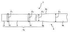
次に、図2を使って、内視鏡2の挿入部7を詳細に説明する。
図2に示すように、内視鏡2の挿入部7は、先端側に略チューブ形状の第1の軟性部7aと、基端側に略チューブ形状の第2の軟性部(第2の可撓管部とも言う)6bと、によって構成されている。
第1の軟性部7aは、先端側から順に、先端部4、湾曲部5及び後述する第1の可撓管部6aから構成され、先端側に先端部4と湾曲部5の接続部である先端側連結部13と、基端側に湾曲部5と可撓管部6の接続部である基端側連結部14がある。この先端側連結部13は、先端部4及び湾曲部5よりも大きい外径寸法d1を有し、先端部4と湾曲部5を所定の接続強度が保たれるように連結している。また、基端側連結部14は、湾曲部5及び可撓管部6の後述する可撓管部6aよりも大きい外径寸法d2を有し、湾曲部5と可撓管部6を所定の接続強度が保たれるように連結している。Next, the
As shown in FIG. 2, the
The first
内視鏡2の可撓管部6は、図2に示すように、先端側から基端側に向けて2段階に外径が大きくなっている。つまり、内視鏡2の可撓管部6は、先端側が細径であって、基端側が太径である2段階に太さが変わる略チューブ形状をしており、先端側の細径の部分に第1の軟性部7aの一部分である第1の可撓管部(以下、細径可撓管部という)6aと、基端側の太径の部分に第2の軟性部である第2の可撓管部(以下、太径可撓管部という)6bとを有している。 As shown in FIG. 2, the
細径可撓管部6aは、略全長が一定の外径寸法d3を有する略チューブ形状をしている。また、太径可撓管部6bは、略全長が細径可撓管部6aの外径寸法d3よりも大きい一定の外径寸法d4(d3<d4)を有する略チューブ形状をしている。また、内視鏡2の可撓管部6は、細径可撓管部6aと太径可撓管部6bの境界部分の外周面が滑らかな段差となるようにテーパ状に形成されたテーパ面6cを有する。 The small-diameter
内視鏡2の可撓管部6の先端部分である細径可撓管部6aは、可撓管部6の基端部分である太径可撓管部6bよりも外皮の肉厚が薄く形成され、太径可撓管部6bよりも可撓性が高く設定される。つまり、可撓管部6は、先端部分の方が可撓性が高く、基端部分の方が可撓性が低い。なお、本実施の形態において、可撓性が低いとは、挿入部7の可撓管部6の太径可撓管部6bの硬度が細径可撓管部6aよりも高い、すなわち、撓み難いということである。一方、可撓性が高いとは、挿入部7の可撓管部6の細径可撓管部6aの硬度が太径可撓管部6bよりも低く撓み易いということである。 The thin
また、内視鏡2の太径可撓管部6bの外径寸法d4は、先端側連結部13の外径寸法d1及び基端側連結部14の外径寸法d2と同等以上(d1≦d4,d2≦d4)である。つまり、内視鏡2の可撓管部6の太径可撓管部6bの外周部は、挿入部7における最大外径部となる。言い換えると、挿入部7の第2の軟性部である太径可撓管部6bの外径寸法d4は、可撓管部6よりも先端側、つまり、第1の軟性部7aの最も大きな外周部の外径寸法と同等以上であって、挿入部7における最大外径寸法となる。 The outer diameter dimension d4 of the large-diameter
次に、図3を使ってオーバーチューブ20を詳細に説明する。
図3に示すように、オーバーチューブ20は、挿入管部21の先端部分に弾性体、例えばゴムなどからなる略円環状のシール部23を備え、所定の可撓性を有する例えば、合成樹脂などからなる略チューブ形状をしている。このオーバーチューブ20は、内視鏡2の挿入部7が挿通される挿通孔20aを有している。このオーバーチューブ20の挿通孔20aは、内視鏡2の可撓管部6の太径可撓管部6bの外径寸法d4よりも若干に大きな内径寸法d5(d4<d5)を有している。なお、挿通孔20aの内径寸法d5は、図2に示した内視鏡2の可撓管部6の太径可撓管部6bの外径寸法d4と略同等(d4≒d5)にしても良い。Next, the
As shown in FIG. 3, the
オーバーチューブ20のシール部23は、開口部分が可撓管部6の太径可撓管部6bの外径寸法d4と同等の内径寸法d6(d4=d6)を有している。つまり、オーバーチューブ20は、先端部分のシール部23の開口部分が最小内径部となる。また、オーバーチューブ20のシール部23の先端側の外周には、テーパ状に形成されたテーパ面23aを有している。なお、シール部23の開口部分の内径寸法d5は、可撓管部6の太径可撓管部6bがシール部23の弾性変形を利用して挿通できる程度に外径寸法d4よりも若干に小さい内径寸法d6(d4>d5)にしても良い。さらに、オーバチューブ20のシール部23は、弾性体に限ることなく、例えば、合成樹脂などでも良い。 The
従って、オーバーチューブ20は、先端側の開口部分である最小内径部の内径寸法d5が内視鏡2の先端側連結部13の外径寸法d1及び基端側連結部14の外径寸法d2の夫々と同等以上の内径寸法d5(d1≦d5,d2≦d5)となっている。
また、図4に示すように、オーバーチューブ20は、内視鏡2の太径可撓管部6bの長手方向の長さ(全長)L1よりも短い長手方向の長さ(全長)L2(L1>L2)を有している。Therefore, the
Further, as shown in FIG. 4, the
次に、このように構成された内視鏡システム1を使った大腸の内視鏡検査について説明する。
まず、術者は、患者の大腸に内視鏡2の挿入部7を挿入する前に、内視鏡2の挿入部7をオーバーチューブ20のオーバーチューブ把持部22側の開口部から挿通孔20a内に挿入する。図5に示すように、術者は、内視鏡2の先端部分をオーバーチューブ20のシール部23の先端側の開口部を通過させ、挿入部7をオーバーチューブ20に貫挿させる。このとき、内視鏡2の先端側連結部13及び基端側連結部14は、夫々の外径部の外径寸法d1,d2がオーバーチューブ20の最小内径部の内径寸法d6と同等以下であるため、オーバーチューブ20の先端側の開口部を通過することができる。なお、図5は、内視鏡2の先端部分がオーバーチューブ20に挿入されている状態の部分断面図である。Next, an endoscopic examination of the large intestine using the endoscope system 1 configured as described above will be described.
First, before inserting the
術者は、図4に示すように、内視鏡2の操作部3の折れ止め部12の近傍にオーバーチューブ20のオーバーチューブ把持部22が位置するまで、内視鏡2の挿入部7をオーバーチューブ20に挿入する。この状態において、オーバーチューブ20の全長L2が内視鏡2の太径可撓管部6bの全長L1よりも短いため、挿入部7の太径可撓管部6bの先端部分は、オーバーチューブ20に覆われていない状態となる。また、図6に示すように、シール部23の開口部の内径と太径可撓管部6bの外径が同等であるため、オーバーチューブ20のシール部23の先端側の開口部分の内周面と内視鏡2の太径可撓管部6bの外周面とが密着している状態となる。さらに、図6に示すように、内視鏡2の太径可撓管部6bの外周面とオーバチューブ20の内周面との間が若干の隙間を有する。そのため、術者は、内視鏡2の挿入部7の太径可撓管部6bの全長の範囲内において、オーバーチューブ20のシール部23の先端側の開口部分の内周面と内視鏡2の太径可撓管部6bの外周面とが密着している状態が保たれながら、オーバーチューブ20のスライド操作が行える。言い換えると、オーバーチューブ20は、内視鏡2の太径可撓管部6bがオーバーチューブ20に覆われていない部分の長さ(L1−L2)の範囲内において、シール部23の先端側の開口部分の内周面と内視鏡2の太径可撓管部6bの外周面とが密着している状態を保ちながらスライド操作がされる。このとき、オーバーチューブ20のシール部23の先端側の開口部分は、常に、その内周面と内視鏡2の太径可撓管部6bの外周面とを密着している。なお、図6は、内視鏡2の太径可撓管部6b上にオーバチューブ20が外挿されている状態の部分断面図である。 As shown in FIG. 4, the operator holds the
次に、術者は、オーバチューブ20が外挿されている内視鏡2の挿入部7を先端部4側から大腸内への挿入作業を行う。
術者は、大腸内の屈曲状態に合わせ、内視鏡2の操作部3の湾曲操作ノブ9を操作する。そして、術者は、内視鏡2の湾曲部5を湾曲操作しながら先端部4を所望の方向に向かせ挿入部7を大腸の深部方向に挿入してゆく。このとき、内視鏡2の挿入部7は、可撓管部6の細径可撓管部6aの可撓性が高いため、細径可撓管部6aが湾曲部5の湾曲に追従してS状結腸部などの屈曲に合わせて挿入される。Next, the surgeon inserts the
The surgeon operates the bending
この可撓管部6の細径可撓管部6aがS状結腸部などの屈曲部の通過後、術者は、オーバチューブ20を太径可撓管部6b上の範囲内においてスライド操作しながら大腸の屈曲を適宜、延伸させて内視鏡2の挿入部7を大腸の深部方向に挿入してゆく。また、術者は、内視鏡2の太径可撓管部6bを把持して、挿入部7を捻り操作しながら大腸の深部方向に挿入する。このとき、オーバチューブ20がスライド操作されている間においても、オーバチューブ20の先端部分のシール部23は、先端側の開口部分の内周面と内視鏡2の太径可撓管部6bの外周面とが常に密着している状態を保っている。さらに、オーバーチューブ20は、所定の可撓性によって大腸が縮まろうとする力を抑え、内視鏡2の太径可撓管部6bの挿通路が確保される。 After the thin
こうして、術者は、湾曲部5の湾曲操作及びオーバーチューブ20を可撓管部6の太径可撓管部6b上の範囲内においてスライド操作を行いながら、内視鏡2の挿入部7を大腸深部へ挿入していく。さらに、術者は、内視鏡2の太径可撓管部6bを把持して、挿入部7の捻り操作などを行いながら、先端部4を大腸深部、例えば盲腸近傍まで到達させることができる。 Thus, the surgeon performs the bending operation of the bending
次に、術者は、内視鏡2の挿入部7を盲腸近傍から徐々に肛門側に抜き取りながら大腸内の内視鏡検査を行う。内視鏡2の挿入部7の抜き取り時においても、術者は、オーバーチューブ20が可撓管部6の太径可撓管部6bを外挿している状態を保ちながら、オーバーチューブ20と挿入部7とを一緒に抜き取りながら大腸内の内視鏡検査を行う。そして、術者は、被検部位の観察、処置などを行った後、内視鏡2の挿入部7をオーバーチューブ20と共に患者の体腔内から抜去する。 Next, the surgeon performs endoscopic examination in the large intestine while gradually removing the
以上の結果、本実施の内視鏡システム1である内視鏡2及びオーバーチューブ20を併用した大腸などの体腔内の内視鏡検査において、内視鏡2の可撓管部6の太径可撓管部6bの外周面とオーバーチューブ20の先端部分にあるシール部23の開口部分の内周面とが常に密着しているため、オーバーチューブ20の内周面と太径可撓管部6bの外周面との隙間には、大腸内の汚物が入り込まない。つまり、大腸内の汚物は、オーバーチューブ20の内周面と太径可撓管部6bの外周面との隙間へ入り込むのが阻止される。従って、オーバーチューブ20の内部には、大腸内の汚物が入り込むことが防止される。 As a result, in the endoscopic examination in the body cavity such as the large intestine using the
その結果、大腸内の汚物がオーバチューブ20の内周面と内視鏡2の太径可撓管部6bの外周面との隙間を伝って、オーバチューブ20のオーバーチューブ把持部22の開口から流出することが防止される。従って、検査室に汚物が飛散することが防止される。 As a result, filth in the large intestine travels through the gap between the inner peripheral surface of the
また、内視鏡2の挿入部7は、先端部分が可撓性の高い、すなわち、撓み易い第1の軟性部7bの一部分である細径可撓管部6aによって、湾曲部5の湾曲動作に追従し易く、大腸の屈曲部の挿入性が向上される。さらに、内視鏡2の挿入部7は、基端部分が可撓性の低い、すなわち、撓み難い第2の軟性部である太径可撓管部6bによって、大腸が縮まろうとする力に影響を受け難い。そのため、術者は、大腸への内視鏡2の挿入部7の挿入が容易となる。
さらに、術者は、内視鏡2の太径可撓管部6bが太径であるため、太径可撓管部6bを把持し易いため、挿入部7を大腸への挿入操作である捻り操作及び押し込み操作が容易となる。Further, the
Furthermore, since the large diameter
なお、図7に示すように、挿入部7の先端部分に先端部4に代えてカプセル型内視鏡50を備えても良い。つまり、第1の軟性部7aは、先端から順にカプセル型内視鏡50、湾曲部5及び細径軟性部6aによって構成されている。この場合、挿入部7における可撓管部6の細径可撓管部6aよりも先端部分の最大外径は、カプセル型内視鏡50の外径寸法d7となる。そのため、挿入部7の第2の軟性部である太径可撓管部6bの外径寸法d4は、カプセル型内視鏡50の外径寸法d7と略同等以上(d7≦d4)となる。つまり、内視鏡2の太径可撓管部6bの外周部は、可撓管部6よりも先端側、つまり、第1の軟性部7aの最も大きな外周部の外径寸法と同等以上の外径寸法d4を有するため、挿入部7においての最大外径部となる。また、先に述べたように、オーバーチューブ20は、シール部23の開口部が可撓管部6の太径可撓管部6bの外径寸法d4と同等の内径寸法d6(d4=d6)を有しているものである。従って、挿入部7の先端部分に先端部4に代えてカプセル型内視鏡50を備える内視鏡2においても、上述の第1の実施の形態と同じ効果が得られる。 As shown in FIG. 7, a
1・・・内視鏡システム、2・・・内視鏡、3・・・操作部、4・・・先端部、5・・・湾曲部、6b・・・太径可撓管部(第2の軟性部)、6a・・・細径可撓管部、6・・・可撓管部、7・・・挿入部、7a・・・第1の軟性部、8・・・ユニバーサルコード、9・・・湾曲操作ノブ、10・・・内視鏡用オーバーチューブ(内視鏡用挿入補助具)、10・・・送気送水ボタン、11・・・吸引ボタン、12・・・折れ止め部、13・・・先端側連結部、14・・・基端側連結部、15・・・把持部、20・・・内視鏡用オーバーチューブ、20a・・・挿通孔、21・・・挿入管部、22・・・オーバーチューブ把持部、23・・・シール部
代理人 弁理士 伊 藤 進
DESCRIPTION OF SYMBOLS 1 ... Endoscope system, 2 ... Endoscope, 3 ... Operation part, 4 ... Tip part, 5 ... Bending part, 6b ... Large diameter flexible tube part (No. 2 soft part), 6a ... thin flexible tube part, 6 ... flexible tube part, 7 ... insertion part, 7a ... first soft part, 8 ... universal cord, DESCRIPTION OF
Claims (5)
Translated fromJapanese前記挿入部の先端側に略チューブ形状の第1の軟性部と、
前記挿入部の基端側に略チューブ形状の第2の軟性部と、
を備え、
前記第2の軟性部の外径寸法は、前記第1の軟性部の最大外径寸法を有する部分の外径寸法よりも大きいことを特徴とする内視鏡。An endoscope having an insertion portion that is inserted into a body cavity extending from an operation portion,
A first tube-shaped first flexible portion on the distal end side of the insertion portion;
A substantially tube-shaped second flexible portion on the proximal end side of the insertion portion;
With
The endoscope characterized in that an outer diameter size of the second soft portion is larger than an outer diameter size of a portion having the maximum outer diameter size of the first soft portion.
前記挿入部が挿入される略チューブ形状の内視鏡挿入補助具と、
を具備し、
前記第2の軟性部の外径寸法は、前記第1の軟性部の最大外径寸法を有する部分の外径寸法よりも大きく、且つ、前記内視鏡用挿入補助具の先端側の開口部の内径寸法は、前記第2の軟性部の外形寸法と略同等であることを特徴とする内視鏡システム。An insertion portion that has a first tube-shaped first flexible portion on the distal end side and a second tube-shaped second flexible portion on the proximal end side, and is inserted into a body cavity extending from the operation portion;
A substantially tube-shaped endoscope insertion aid into which the insertion portion is inserted;
Comprising
The outer diameter of the second soft part is larger than the outer diameter of the part having the maximum outer diameter of the first soft part, and the opening on the distal end side of the insertion aid for endoscope An internal diameter dimension of the endoscope system is substantially the same as the external dimension of the second soft part.
5. The endoscope system according to claim 3, wherein an overall length of the second flexible portion of the endoscope is longer than an overall length of the endoscope insertion assisting tool. .
Priority Applications (5)
| Application Number | Priority Date | Filing Date | Title |
|---|---|---|---|
| JP2004196062AJP2006014960A (en) | 2004-07-01 | 2004-07-01 | Endoscope |
| CN200580020620.0ACN100558285C (en) | 2004-07-01 | 2005-06-23 | Endoscope insertion portion, endoscope, and endoscope system |
| EP05765066AEP1769717A4 (en) | 2004-07-01 | 2005-06-23 | Endoscope insert part, endoscope, and endoscope system |
| PCT/JP2005/011542WO2006003836A1 (en) | 2004-07-01 | 2005-06-23 | Endoscope insert part, endoscope, and endoscope system |
| US11/642,557US8465419B2 (en) | 2004-07-01 | 2006-12-20 | Endoscope insertion unit, endoscope and endoscope system |
Applications Claiming Priority (1)
| Application Number | Priority Date | Filing Date | Title |
|---|---|---|---|
| JP2004196062AJP2006014960A (en) | 2004-07-01 | 2004-07-01 | Endoscope |
Publications (1)
| Publication Number | Publication Date |
|---|---|
| JP2006014960Atrue JP2006014960A (en) | 2006-01-19 |
Family
ID=35782647
Family Applications (1)
| Application Number | Title | Priority Date | Filing Date |
|---|---|---|---|
| JP2004196062APendingJP2006014960A (en) | 2004-07-01 | 2004-07-01 | Endoscope |
Country Status (5)
| Country | Link |
|---|---|
| US (1) | US8465419B2 (en) |
| EP (1) | EP1769717A4 (en) |
| JP (1) | JP2006014960A (en) |
| CN (1) | CN100558285C (en) |
| WO (1) | WO2006003836A1 (en) |
Cited By (8)
| Publication number | Priority date | Publication date | Assignee | Title |
|---|---|---|---|---|
| JP2013248346A (en)* | 2012-06-04 | 2013-12-12 | Olympus Medical Systems Corp | Endoscope system |
| WO2014157474A1 (en)* | 2013-03-29 | 2014-10-02 | 富士フイルム株式会社 | Surgical device, trocar, endoscope, and treatment tool |
| WO2014157476A1 (en)* | 2013-03-29 | 2014-10-02 | 富士フイルム株式会社 | Surgical device, trocar, endoscope, and treatment tool |
| USD755378S1 (en) | 2014-09-30 | 2016-05-03 | Fujifilm Corporation | Endoscope |
| US9826887B2 (en) | 2013-03-29 | 2017-11-28 | Fujifilm Corporation | Surgical device, outer tube, endoscope, and treatment tool |
| US10264950B2 (en) | 2013-03-29 | 2019-04-23 | Fujifilm Corporation | Endoscopic surgery device |
| US10368723B2 (en) | 2013-03-29 | 2019-08-06 | Fujifilm Corporation | Endoscopic surgery device, method of inserting endoscope and treatment tool, and method of removing endoscope and treatment tool |
| USD855803S1 (en) | 2015-07-30 | 2019-08-06 | Fujifilm Corporation | Endoscope |
Families Citing this family (64)
| Publication number | Priority date | Publication date | Assignee | Title |
|---|---|---|---|---|
| JP3987312B2 (en)* | 2001-08-31 | 2007-10-10 | 株式会社東芝 | Semiconductor device manufacturing apparatus and manufacturing method, and semiconductor manufacturing apparatus cleaning method |
| US7655004B2 (en) | 2007-02-15 | 2010-02-02 | Ethicon Endo-Surgery, Inc. | Electroporation ablation apparatus, system, and method |
| US7815662B2 (en) | 2007-03-08 | 2010-10-19 | Ethicon Endo-Surgery, Inc. | Surgical suture anchors and deployment device |
| US8075572B2 (en)* | 2007-04-26 | 2011-12-13 | Ethicon Endo-Surgery, Inc. | Surgical suturing apparatus |
| US8100922B2 (en) | 2007-04-27 | 2012-01-24 | Ethicon Endo-Surgery, Inc. | Curved needle suturing tool |
| US8568410B2 (en) | 2007-08-31 | 2013-10-29 | Ethicon Endo-Surgery, Inc. | Electrical ablation surgical instruments |
| US8579897B2 (en) | 2007-11-21 | 2013-11-12 | Ethicon Endo-Surgery, Inc. | Bipolar forceps |
| US8262655B2 (en) | 2007-11-21 | 2012-09-11 | Ethicon Endo-Surgery, Inc. | Bipolar forceps |
| US8480657B2 (en) | 2007-10-31 | 2013-07-09 | Ethicon Endo-Surgery, Inc. | Detachable distal overtube section and methods for forming a sealable opening in the wall of an organ |
| US20090112059A1 (en) | 2007-10-31 | 2009-04-30 | Nobis Rudolph H | Apparatus and methods for closing a gastrotomy |
| US8262680B2 (en) | 2008-03-10 | 2012-09-11 | Ethicon Endo-Surgery, Inc. | Anastomotic device |
| US8070759B2 (en) | 2008-05-30 | 2011-12-06 | Ethicon Endo-Surgery, Inc. | Surgical fastening device |
| US8679003B2 (en) | 2008-05-30 | 2014-03-25 | Ethicon Endo-Surgery, Inc. | Surgical device and endoscope including same |
| US8652150B2 (en) | 2008-05-30 | 2014-02-18 | Ethicon Endo-Surgery, Inc. | Multifunction surgical device |
| US8771260B2 (en) | 2008-05-30 | 2014-07-08 | Ethicon Endo-Surgery, Inc. | Actuating and articulating surgical device |
| US8114072B2 (en) | 2008-05-30 | 2012-02-14 | Ethicon Endo-Surgery, Inc. | Electrical ablation device |
| US8317806B2 (en) | 2008-05-30 | 2012-11-27 | Ethicon Endo-Surgery, Inc. | Endoscopic suturing tension controlling and indication devices |
| US8906035B2 (en) | 2008-06-04 | 2014-12-09 | Ethicon Endo-Surgery, Inc. | Endoscopic drop off bag |
| US8403926B2 (en) | 2008-06-05 | 2013-03-26 | Ethicon Endo-Surgery, Inc. | Manually articulating devices |
| US8361112B2 (en) | 2008-06-27 | 2013-01-29 | Ethicon Endo-Surgery, Inc. | Surgical suture arrangement |
| US8888792B2 (en) | 2008-07-14 | 2014-11-18 | Ethicon Endo-Surgery, Inc. | Tissue apposition clip application devices and methods |
| US8262563B2 (en) | 2008-07-14 | 2012-09-11 | Ethicon Endo-Surgery, Inc. | Endoscopic translumenal articulatable steerable overtube |
| US8211125B2 (en) | 2008-08-15 | 2012-07-03 | Ethicon Endo-Surgery, Inc. | Sterile appliance delivery device for endoscopic procedures |
| US8529563B2 (en) | 2008-08-25 | 2013-09-10 | Ethicon Endo-Surgery, Inc. | Electrical ablation devices |
| US8241204B2 (en) | 2008-08-29 | 2012-08-14 | Ethicon Endo-Surgery, Inc. | Articulating end cap |
| US8480689B2 (en) | 2008-09-02 | 2013-07-09 | Ethicon Endo-Surgery, Inc. | Suturing device |
| US8409200B2 (en) | 2008-09-03 | 2013-04-02 | Ethicon Endo-Surgery, Inc. | Surgical grasping device |
| US8114119B2 (en) | 2008-09-09 | 2012-02-14 | Ethicon Endo-Surgery, Inc. | Surgical grasping device |
| US8337394B2 (en) | 2008-10-01 | 2012-12-25 | Ethicon Endo-Surgery, Inc. | Overtube with expandable tip |
| US9867529B2 (en) | 2008-11-07 | 2018-01-16 | Izoscope Inc | Endoscope accessory |
| US9480390B2 (en) | 2008-11-07 | 2016-11-01 | Ashkan Farhadi | Endoscope accessory |
| US8157834B2 (en) | 2008-11-25 | 2012-04-17 | Ethicon Endo-Surgery, Inc. | Rotational coupling device for surgical instrument with flexible actuators |
| US8172772B2 (en) | 2008-12-11 | 2012-05-08 | Ethicon Endo-Surgery, Inc. | Specimen retrieval device |
| US8828031B2 (en) | 2009-01-12 | 2014-09-09 | Ethicon Endo-Surgery, Inc. | Apparatus for forming an anastomosis |
| US8361066B2 (en) | 2009-01-12 | 2013-01-29 | Ethicon Endo-Surgery, Inc. | Electrical ablation devices |
| US8252057B2 (en) | 2009-01-30 | 2012-08-28 | Ethicon Endo-Surgery, Inc. | Surgical access device |
| US9226772B2 (en) | 2009-01-30 | 2016-01-05 | Ethicon Endo-Surgery, Inc. | Surgical device |
| US8037591B2 (en) | 2009-02-02 | 2011-10-18 | Ethicon Endo-Surgery, Inc. | Surgical scissors |
| US20110098704A1 (en) | 2009-10-28 | 2011-04-28 | Ethicon Endo-Surgery, Inc. | Electrical ablation devices |
| US8608652B2 (en) | 2009-11-05 | 2013-12-17 | Ethicon Endo-Surgery, Inc. | Vaginal entry surgical devices, kit, system, and method |
| US8353487B2 (en) | 2009-12-17 | 2013-01-15 | Ethicon Endo-Surgery, Inc. | User interface support devices for endoscopic surgical instruments |
| US8496574B2 (en) | 2009-12-17 | 2013-07-30 | Ethicon Endo-Surgery, Inc. | Selectively positionable camera for surgical guide tube assembly |
| US9028483B2 (en) | 2009-12-18 | 2015-05-12 | Ethicon Endo-Surgery, Inc. | Surgical instrument comprising an electrode |
| US8506564B2 (en) | 2009-12-18 | 2013-08-13 | Ethicon Endo-Surgery, Inc. | Surgical instrument comprising an electrode |
| US9005198B2 (en) | 2010-01-29 | 2015-04-14 | Ethicon Endo-Surgery, Inc. | Surgical instrument comprising an electrode |
| US10092291B2 (en) | 2011-01-25 | 2018-10-09 | Ethicon Endo-Surgery, Inc. | Surgical instrument with selectively rigidizable features |
| US9314620B2 (en) | 2011-02-28 | 2016-04-19 | Ethicon Endo-Surgery, Inc. | Electrical ablation devices and methods |
| US9233241B2 (en) | 2011-02-28 | 2016-01-12 | Ethicon Endo-Surgery, Inc. | Electrical ablation devices and methods |
| US9254169B2 (en) | 2011-02-28 | 2016-02-09 | Ethicon Endo-Surgery, Inc. | Electrical ablation devices and methods |
| US9049987B2 (en) | 2011-03-17 | 2015-06-09 | Ethicon Endo-Surgery, Inc. | Hand held surgical device for manipulating an internal magnet assembly within a patient |
| US8986199B2 (en) | 2012-02-17 | 2015-03-24 | Ethicon Endo-Surgery, Inc. | Apparatus and methods for cleaning the lens of an endoscope |
| US9427255B2 (en) | 2012-05-14 | 2016-08-30 | Ethicon Endo-Surgery, Inc. | Apparatus for introducing a steerable camera assembly into a patient |
| US9078662B2 (en) | 2012-07-03 | 2015-07-14 | Ethicon Endo-Surgery, Inc. | Endoscopic cap electrode and method for using the same |
| US9545290B2 (en) | 2012-07-30 | 2017-01-17 | Ethicon Endo-Surgery, Inc. | Needle probe guide |
| US9572623B2 (en) | 2012-08-02 | 2017-02-21 | Ethicon Endo-Surgery, Inc. | Reusable electrode and disposable sheath |
| US10314649B2 (en) | 2012-08-02 | 2019-06-11 | Ethicon Endo-Surgery, Inc. | Flexible expandable electrode and method of intraluminal delivery of pulsed power |
| US9277957B2 (en) | 2012-08-15 | 2016-03-08 | Ethicon Endo-Surgery, Inc. | Electrosurgical devices and methods |
| US10098527B2 (en) | 2013-02-27 | 2018-10-16 | Ethidcon Endo-Surgery, Inc. | System for performing a minimally invasive surgical procedure |
| US9610005B2 (en) | 2013-07-18 | 2017-04-04 | Ashkan Farhadi | Methods, devices and systems for improved hygiene during endoscopic procedures |
| US11096569B2 (en)* | 2014-10-15 | 2021-08-24 | Covidien Lp | Endoscope with a multiple diameter working section |
| WO2016194450A1 (en)* | 2015-06-02 | 2016-12-08 | オリンパス株式会社 | Endoscope |
| CN108366710B (en)* | 2015-11-20 | 2020-08-11 | 奥林巴斯株式会社 | Endoscope system |
| DE202018104602U1 (en) | 2018-08-10 | 2018-08-17 | Lohmann & Rauscher Gmbh | protective sleeve |
| CN113899129A (en)* | 2020-07-06 | 2022-01-07 | 博西华电器(江苏)有限公司 | Refrigerator with a door |
Citations (10)
| Publication number | Priority date | Publication date | Assignee | Title |
|---|---|---|---|---|
| JPH02139603A (en)* | 1988-11-21 | 1990-05-29 | Mitsubishi Electric Corp | numerical control device |
| JPH0373126A (en)* | 1989-08-14 | 1991-03-28 | Toshiba Corp | Sliding tube for endoscope |
| JPH0638923A (en)* | 1992-07-21 | 1994-02-15 | Olympus Optical Co Ltd | Leading attachment for endoscope |
| JPH0670879A (en)* | 1992-06-26 | 1994-03-15 | Toshiba Corp | Endoscope system |
| JPH08547A (en)* | 1994-06-23 | 1996-01-09 | Koushinshiya:Kk | Endoscope insertion guide |
| JP2001190494A (en)* | 2000-01-06 | 2001-07-17 | Asahi Optical Co Ltd | Flexible tube of endoscope |
| JP2002186579A (en)* | 2000-12-22 | 2002-07-02 | Olympus Optical Co Ltd | Endoscope insertion assist device |
| JP2002209835A (en)* | 2001-01-15 | 2002-07-30 | Fuji Photo Optical Co Ltd | Intercelom diagnostic device |
| JP2002369791A (en)* | 2001-06-14 | 2002-12-24 | Pentax Corp | Endoscope system and endoscope insertion aid |
| JP2004141492A (en)* | 2002-10-25 | 2004-05-20 | Olympus Corp | Endoscope |
Family Cites Families (18)
| Publication number | Priority date | Publication date | Assignee | Title |
|---|---|---|---|---|
| DE2626179A1 (en)* | 1976-06-11 | 1977-12-22 | Karl Storz | RECTOSCOPE, IN PARTICULAR FOR AIR INFLATION AND METHOD OF APPLYING THE SAME |
| JPS56148332A (en)* | 1980-04-22 | 1981-11-17 | Olympus Optical Co | Tracheal |
| US4588398A (en)* | 1984-09-12 | 1986-05-13 | Warner-Lambert Company | Catheter tip configuration |
| US5083549A (en) | 1989-02-06 | 1992-01-28 | Candela Laser Corporation | Endoscope with tapered shaft |
| DE3912797C1 (en)* | 1989-04-19 | 1990-11-08 | Richard Wolf Gmbh, 7134 Knittlingen, De | |
| US5002558A (en)* | 1989-08-23 | 1991-03-26 | The Beth Israel Hospital Association | Adjustable urethral catheter and method for treating obstructive prostatism |
| US5078681A (en)* | 1989-10-23 | 1992-01-07 | Olympus Optical Co., Ltd. | Balloon catheter apparatus with releasable distal seal and method of operation |
| WO1995024149A1 (en) | 1994-03-07 | 1995-09-14 | Conceptus, Inc. | Method and apparatus for performing hysteroscopic and falloposcopic procedures |
| US5779624A (en)* | 1996-12-05 | 1998-07-14 | Boston Scientific Corporation | Sigmoid splint device for endoscopy |
| US5779697A (en)* | 1997-05-28 | 1998-07-14 | Linvatec Corporation | Arthroscopic cannula with fluid seals |
| US6234958B1 (en)* | 1998-11-30 | 2001-05-22 | Medical Access Systems, Llc | Medical device introduction system including medical introducer having a plurality of access ports and methods of performing medical procedures with same |
| JP2000325301A (en)* | 1999-05-18 | 2000-11-28 | Asahi Optical Co Ltd | Colonoscope insertion aid |
| US6858005B2 (en)* | 2000-04-03 | 2005-02-22 | Neo Guide Systems, Inc. | Tendon-driven endoscope and methods of insertion |
| US6837846B2 (en)* | 2000-04-03 | 2005-01-04 | Neo Guide Systems, Inc. | Endoscope having a guide tube |
| JP3831683B2 (en)* | 2002-05-16 | 2006-10-11 | ペンタックス株式会社 | Bending prevention of flexible tube insertion part of endoscope with outer sheath |
| US6852078B2 (en)* | 2002-05-22 | 2005-02-08 | Pentax Corporation | Outer sheathed endoscope |
| CN2538293Y (en)* | 2002-06-05 | 2003-03-05 | 令狐恩强 | Exhausting preventing valve for external sleeve of endoscope |
| US6790173B2 (en)* | 2002-06-13 | 2004-09-14 | Usgi Medical, Inc. | Shape lockable apparatus and method for advancing an instrument through unsupported anatomy |
- 2004
- 2004-07-01JPJP2004196062Apatent/JP2006014960A/enactivePending
- 2005
- 2005-06-23EPEP05765066Apatent/EP1769717A4/ennot_activeWithdrawn
- 2005-06-23WOPCT/JP2005/011542patent/WO2006003836A1/ennot_activeApplication Discontinuation
- 2005-06-23CNCN200580020620.0Apatent/CN100558285C/ennot_activeExpired - Fee Related
- 2006
- 2006-12-20USUS11/642,557patent/US8465419B2/ennot_activeExpired - Fee Related
Patent Citations (10)
| Publication number | Priority date | Publication date | Assignee | Title |
|---|---|---|---|---|
| JPH02139603A (en)* | 1988-11-21 | 1990-05-29 | Mitsubishi Electric Corp | numerical control device |
| JPH0373126A (en)* | 1989-08-14 | 1991-03-28 | Toshiba Corp | Sliding tube for endoscope |
| JPH0670879A (en)* | 1992-06-26 | 1994-03-15 | Toshiba Corp | Endoscope system |
| JPH0638923A (en)* | 1992-07-21 | 1994-02-15 | Olympus Optical Co Ltd | Leading attachment for endoscope |
| JPH08547A (en)* | 1994-06-23 | 1996-01-09 | Koushinshiya:Kk | Endoscope insertion guide |
| JP2001190494A (en)* | 2000-01-06 | 2001-07-17 | Asahi Optical Co Ltd | Flexible tube of endoscope |
| JP2002186579A (en)* | 2000-12-22 | 2002-07-02 | Olympus Optical Co Ltd | Endoscope insertion assist device |
| JP2002209835A (en)* | 2001-01-15 | 2002-07-30 | Fuji Photo Optical Co Ltd | Intercelom diagnostic device |
| JP2002369791A (en)* | 2001-06-14 | 2002-12-24 | Pentax Corp | Endoscope system and endoscope insertion aid |
| JP2004141492A (en)* | 2002-10-25 | 2004-05-20 | Olympus Corp | Endoscope |
Cited By (15)
| Publication number | Priority date | Publication date | Assignee | Title |
|---|---|---|---|---|
| JP2013248346A (en)* | 2012-06-04 | 2013-12-12 | Olympus Medical Systems Corp | Endoscope system |
| US10292576B2 (en) | 2013-03-29 | 2019-05-21 | Fujifilm Corporation | Surgical device, outer tube, endoscope, and treatment tool |
| US10264950B2 (en) | 2013-03-29 | 2019-04-23 | Fujifilm Corporation | Endoscopic surgery device |
| US11547284B2 (en) | 2013-03-29 | 2023-01-10 | Fujifilm Corporation | Endoscopic surgery device |
| JPWO2014157474A1 (en)* | 2013-03-29 | 2017-02-16 | 富士フイルム株式会社 | Surgical device and mantle |
| JPWO2014157476A1 (en)* | 2013-03-29 | 2017-02-16 | 富士フイルム株式会社 | Surgical device and mantle |
| US9826887B2 (en) | 2013-03-29 | 2017-11-28 | Fujifilm Corporation | Surgical device, outer tube, endoscope, and treatment tool |
| US10064650B2 (en) | 2013-03-29 | 2018-09-04 | Fujifilm Corporation | Surgical device, outer tube, endoscope, and treatment tool |
| WO2014157476A1 (en)* | 2013-03-29 | 2014-10-02 | 富士フイルム株式会社 | Surgical device, trocar, endoscope, and treatment tool |
| WO2014157474A1 (en)* | 2013-03-29 | 2014-10-02 | 富士フイルム株式会社 | Surgical device, trocar, endoscope, and treatment tool |
| US10368723B2 (en) | 2013-03-29 | 2019-08-06 | Fujifilm Corporation | Endoscopic surgery device, method of inserting endoscope and treatment tool, and method of removing endoscope and treatment tool |
| US10485407B2 (en) | 2013-03-29 | 2019-11-26 | Fujifilm Corporation | Surgical device, outer tube, endoscope, and treatment tool |
| USD755378S1 (en) | 2014-09-30 | 2016-05-03 | Fujifilm Corporation | Endoscope |
| USD855803S1 (en) | 2015-07-30 | 2019-08-06 | Fujifilm Corporation | Endoscope |
| USD915587S1 (en) | 2015-07-30 | 2021-04-06 | Fujifilm Corporation | Endoscope |
Also Published As
| Publication number | Publication date |
|---|---|
| US8465419B2 (en) | 2013-06-18 |
| CN100558285C (en) | 2009-11-11 |
| CN1972625A (en) | 2007-05-30 |
| EP1769717A1 (en) | 2007-04-04 |
| WO2006003836A1 (en) | 2006-01-12 |
| US20070106118A1 (en) | 2007-05-10 |
| EP1769717A4 (en) | 2009-08-12 |
Similar Documents
| Publication | Publication Date | Title |
|---|---|---|
| CN100558285C (en) | Endoscope insertion portion, endoscope, and endoscope system | |
| US12004712B2 (en) | Medical device kit with endoscope accessory | |
| CN211985342U (en) | Soft lens leading-in device | |
| JP5166133B2 (en) | Endoscope | |
| AU752555B2 (en) | Video rectoscope | |
| US20150080764A1 (en) | Disposable instrument including working channels for endoscopy | |
| JP2009528894A (en) | Endoscope elevator device | |
| JP2009528899A (en) | Endoscopic catheter device having radial grooves | |
| WO2019087550A1 (en) | Endoscopic device | |
| JP2010523219A (en) | Endoscopic device having an external rail | |
| JP4524393B2 (en) | Rapalloport | |
| JP5496140B2 (en) | Endoscope insertion aid | |
| JP2023521171A (en) | Endoscopic combined device with locking element | |
| JP3422213B2 (en) | Endoscope guide device | |
| JP4777005B2 (en) | Endoscope | |
| JP6899316B2 (en) | Lacrimal duct endoscopy | |
| JP2007203122A (en) | Over-tube | |
| JPH08280603A (en) | Cover type endoscope | |
| JPH06261855A (en) | Endoscope device of endoscope cover system | |
| JP6720016B2 (en) | Sheath device for endoscope system | |
| JP2006247287A (en) | Endoscope cover and endoscope system using it | |
| JP2018175225A (en) | Endoscope system | |
| CN116211222A (en) | Guiding device and endoscope for endoscope | |
| CN117017371A (en) | Instrument tube, insertion part and endoscope | |
| JP2009183333A (en) | Endoscope for medical checkup |
Legal Events
| Date | Code | Title | Description |
|---|---|---|---|
| A621 | Written request for application examination | Free format text:JAPANESE INTERMEDIATE CODE: A621 Effective date:20070510 | |
| A131 | Notification of reasons for refusal | Free format text:JAPANESE INTERMEDIATE CODE: A131 Effective date:20091222 | |
| A521 | Request for written amendment filed | Free format text:JAPANESE INTERMEDIATE CODE: A523 Effective date:20100217 | |
| A131 | Notification of reasons for refusal | Free format text:JAPANESE INTERMEDIATE CODE: A131 Effective date:20100413 | |
| A521 | Request for written amendment filed | Free format text:JAPANESE INTERMEDIATE CODE: A523 Effective date:20100614 | |
| A131 | Notification of reasons for refusal | Free format text:JAPANESE INTERMEDIATE CODE: A131 Effective date:20100803 | |
| A521 | Request for written amendment filed | Free format text:JAPANESE INTERMEDIATE CODE: A523 Effective date:20101001 | |
| A131 | Notification of reasons for refusal | Free format text:JAPANESE INTERMEDIATE CODE: A131 Effective date:20101130 | |
| A02 | Decision of refusal | Free format text:JAPANESE INTERMEDIATE CODE: A02 Effective date:20110405 |