JP2006014094A - Image processing apparatus, image reading apparatus, image forming apparatus, color copying apparatus, image processing program, and recording medium - Google Patents
Image processing apparatus, image reading apparatus, image forming apparatus, color copying apparatus, image processing program, and recording mediumDownload PDFInfo
- Publication number
- JP2006014094A JP2006014094AJP2004190446AJP2004190446AJP2006014094AJP 2006014094 AJP2006014094 AJP 2006014094AJP 2004190446 AJP2004190446 AJP 2004190446AJP 2004190446 AJP2004190446 AJP 2004190446AJP 2006014094 AJP2006014094 AJP 2006014094A
- Authority
- JP
- Japan
- Prior art keywords
- pixel
- color
- white
- image
- data
- Prior art date
- Legal status (The legal status is an assumption and is not a legal conclusion. Google has not performed a legal analysis and makes no representation as to the accuracy of the status listed.)
- Pending
Links
Images


Landscapes
- Image Processing (AREA)
- Facsimile Image Signal Circuits (AREA)
- Color Image Communication Systems (AREA)
Abstract
Translated fromJapaneseDescription
Translated fromJapanese本発明は、カラーデジタル複写機やカラープリンタ、ファクシミリなどの画像形成装置に利用される画像処理装置に関し、詳細には、R、G、B等の複数のイメージセンサで読み取った画像の位置ずれを補正する画像処理装置、画像読取装置、画像形成装置、カラー複写装置、画像処理プログラム及び記録媒体に関する。 The present invention relates to an image processing apparatus used for an image forming apparatus such as a color digital copying machine, a color printer, or a facsimile, and more specifically, positional deviation of an image read by a plurality of image sensors such as R, G, and B. The present invention relates to an image processing apparatus to be corrected, an image reading apparatus, an image forming apparatus, a color copying apparatus, an image processing program, and a recording medium.
従来技術として、注目画素の隣の画素を含む画素の最大値を検出して、基準色に対して正規化を行い色ずれ補正を行い、基準色に正規化後、画素の値が揃う値の正規化前の信号に補正するものがある(例えば、特許文献1参照)。しかし、特許文献1記載の発明は、実施例から推測すると、最大値側(白)で正規化すると、白地上の色文字は彩度が下がる可能性があり、逆に濃い側(黒)で正規化すると黒字上の色文字で彩度の彩度が下がる可能性がある。よって、正規化するのがいいとは限らない。
また、平滑化される色信号の微分値を算出し、微分色信号を基準レベル値と比較し、エッジ部画像の展開幅を検出し、展開幅を用いて形状特徴を算出することにより、色ずれの補正処理を正確にするものやエッヂ部の形状により補正するものがある(例えば、特許文献2、3及び4参照)。しかし、特許文献2〜4記載の発明は、特徴を算出するために、広い領域を見てハード規模も大きくなってしまう。
また、シェーディング板付近に黒線を書き、黒線を基準に補正を行っているものがある(例えば、特許文献5参照)。しかし、特許文献5記載の発明は、基準線で行っているために過渡的振動に対応できないし、位置ずれに関する情報を記憶するメモリが必要になる。
また、副走査方向に基準の黒線に対して補正を行うものがある(例えば、特許文献6参照)。しかし、特許文献6記載の発明は、主走査に適用しようとすると、基準線で行っているために過渡的振動に対応できないし、位置ずれに関する情報を記憶するメモリが必要になる。
また、予め記憶している関数に基づいて補正するものがある(例えば、特許文献7参照)。しかし、特許文献7記載の発明は、記憶している関数は黒線なので色文字に関しては効果不明である。
また、目標濃度を決めて補正を行う発明もあるが、補正する際に、複数の仮想画素を算出してその中から目標濃度に内輪で近いものを選択する。複数の仮想画素を求めなければならない。
Also, by calculating the differential value of the color signal to be smoothed, comparing the differential color signal with the reference level value, detecting the developed width of the edge image, and calculating the shape feature using the developed width, There are ones that make the correction process of deviation accurate, and ones that make correction by the shape of the edge portion (see, for example,
In addition, there is one in which a black line is written near the shading plate and correction is performed based on the black line (see, for example, Patent Document 5). However, since the invention described in
In addition, there is one that corrects a reference black line in the sub-scanning direction (see, for example, Patent Document 6). However, when the invention described in
Some corrections are made based on functions stored in advance (see, for example, Patent Document 7). However, in the invention described in
In addition, there is an invention in which correction is performed by determining a target density, but when correcting, a plurality of virtual pixels are calculated, and one close to the target density is selected from among them. A plurality of virtual pixels must be obtained.
しかしながら、従来、複写機などに用いられるラインセンサを用いると、レンズの収差や取り付け精度により、ラインセンサの先端、中央、後端において主走査方向のRGB位置ずれが生じてしまう。さらに、機械振動で過渡的に副走査方向のRGB読み取り位置が生じてしまう。 However, when a line sensor conventionally used in a copying machine or the like is used, RGB position shifts in the main scanning direction occur at the front end, center, and rear end of the line sensor due to lens aberration and mounting accuracy. Further, the RGB reading position in the sub-scanning direction is generated transiently due to mechanical vibration.
本発明は、上記事情に鑑みてなされたものであり、周辺濃度差と、仮想画素検出手段で、1ライン未満データと1ライン以上のデータの少なくとも4つ以上の仮想画素を算出して、画像データを補正することにより、位置ずれを補正する画像処理装置、ソフトウェア及びカラー複写装置を提供することを目的とする。 The present invention has been made in view of the above circumstances, and calculates at least four or more virtual pixels of data of less than one line and data of one or more lines by using a peripheral density difference and virtual pixel detection means to generate an image. An object of the present invention is to provide an image processing apparatus, software, and a color copying apparatus that correct misalignment by correcting data.
一般にG信号に対して、RとBの読み取りの小数点以下の仮想サンプリング点の画像の濃度を求め、RGBの最小の点を求める。しかし、黒文字は良好に処理できるが、緑などの色文字においては黒くなってしまう。そこで、本発明は、周辺画素の濃度差を参照して、周辺画素の濃度を上限として色文字が黒くならない(彩度低下しない)ようにすることを目的としている。 In general, with respect to the G signal, the density of an image at a virtual sampling point below the decimal point of R and B reading is obtained, and the minimum point of RGB is obtained. However, although black characters can be processed satisfactorily, color characters such as green become black. In view of the above, an object of the present invention is to refer to the density difference between peripheral pixels and prevent the color character from becoming black (saturation does not decrease) with the density of the peripheral pixels as an upper limit.
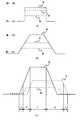
例えば、図15(a)のように黒線があった時に、位置ずれなく読み取った場合、光学系の特性でエッヂが図15(b)の様になる。このデータがずれると図15(c)の様にRGBデータがずれると、Aの幅分のデータが黒にならず色となってしまう。この時は、基準色に対して他の色を近づけることにより、黒色に補正することができる。 For example, when there is a black line as shown in FIG. 15A and the reading is performed without positional deviation, the edge becomes as shown in FIG. 15B due to the characteristics of the optical system. If this data is shifted, if the RGB data is shifted as shown in FIG. 15C, the data corresponding to the width of A is not black but becomes a color. At this time, it can be corrected to black by bringing other colors closer to the reference color.
次に、図28(a)のような緑の場合について説明する。この時も黒線と同様に、図28(b)のような特性となる。これがずれると図28(c)の様になる。この場合は、基準色に対して他の色を基準色に近づくように補正するとA部分は正しく補正されるが、他の部分のB,C,Dは、本来のRGBデータの差が小さくなり、彩度の低下を招き全体的に黒っぽくなってしまう。3ラインCCDで同一の場所、時間をずらして読み取るために過渡的な機械振動を受けると、RGBの読み取り位置がずれてしまう。そこで、本発明は、周辺濃度差と、仮想画素検出手段で、1ライン未満データと1ライン以上のデータの少なくとも4つ以上の仮想画素を算出して、画像データを補正することを目的とする。 Next, the case of green as shown in FIG. At this time, the characteristic is as shown in FIG. When this shifts, it becomes as shown in FIG. In this case, if the other color is corrected so as to approach the reference color with respect to the reference color, the A portion is corrected correctly, but the difference between the original RGB data becomes smaller in the other portions B, C, and D. , Resulting in a decrease in saturation and overall blackness. If the three-line CCD receives transient mechanical vibration to read at the same place and time, the RGB reading position is shifted. SUMMARY OF THE INVENTION Accordingly, an object of the present invention is to correct image data by calculating at least four or more virtual pixels of data of less than one line and data of one line or more with a peripheral density difference and virtual pixel detection means. .
かかる目的を達成するために、請求項1記載の発明は、画像データのRGB入力手段と、R,G,Bの1色を基準として同一画素位置の基準色と基準色以外の色の濃度差を検出する濃度差検出手段と、濃度検出手段を周辺画素に対して行う周辺画素濃度検出手段と、基準画素と以外の2つ色に対して仮想的に位置をずらした画素を2つ以上算出する仮想画素算出手段と、仮想画素算出手段により、求めたデータすべてに対して、注目画素の基準色との濃度差を演算する注目画素濃度差検出手段と、上記注目画素濃度検出の結果と、周辺画素濃度検出手段の算出結果に基づいて仮想画素検出手段の結果のデータで画像データを補正する画像補正手段と、を備えることを特徴とする。 In order to achieve such an object, the invention described in
請求項2記載の発明は、請求項1記載の発明において、画像補正手段は、注目画素と仮想演算手段の結果の間に、目標濃度差があるときに、目標濃度差に補正することを特徴とする。 According to a second aspect of the present invention, in the first aspect of the invention, the image correction unit corrects the target density difference to a target density difference when there is a target density difference between the target pixel and the result of the virtual calculation unit. And
請求項3記載の発明は、請求項1記載の発明において、補正手段は、周辺画素のデータの差が多い所に対して補正を行うことを特徴とする。 According to a third aspect of the present invention, in the first aspect of the present invention, the correction means performs correction for a place where there is a large difference in data of peripheral pixels.
請求項4記載の発明は、請求項1記載の発明において、補正方向は、主走査方向又は副走査方向であることを特徴とする。 According to a fourth aspect of the present invention, in the first aspect of the present invention, the correction direction is a main scanning direction or a sub-scanning direction.
請求項5記載の発明は、請求項1記載の発明において、補正後の画像データを用いて、色文字エッヂ及び黒文字エッヂの色を判定すること特徴とする。 The invention described in
請求項6記載の発明は、請求項1〜5のいずれか1項に記載の画像処理装置と、原稿画像を色分解して読み取って画像データを生成して画像処理装置に与えるカラースキャナと、を備えることを特徴とする。 The invention according to
請求項7記載の発明は、請求項1〜5のいずれか1項に記載の画像処理装置と、出力画像データを用紙上にプリントアウトするカラープリンタを備えることを特徴とする。 A seventh aspect of the invention includes the image processing apparatus according to any one of the first to fifth aspects, and a color printer that prints out output image data on paper.
請求項8記載の発明は、請求項1〜5のいずれか1項に記載の画像処理装置と、原稿画像を色分解して読み取って画像データを生成して画像処理装置に与えるカラースキャナと、画像処理装置の出力画像データを用紙上にプリントアウトするカラープリンタを備えることを特徴とする。 The invention according to
請求項9記載の発明は、請求項8記載の発明において、外部からのプリント指示コマンドを解析してプリンタにて外部からの画像情報をプリントアウトするプリンタコントローラを更に備えることを特徴とする。 According to a ninth aspect of the invention, there is provided the printer according to the eighth aspect, further comprising a printer controller that analyzes a print instruction command from the outside and prints out image information from the outside by a printer.
請求項10記載の発明は、画像データのRGB入力処理と、R,G,Bの1色を基準として同一画素位置の基準色と基準色以外の色の濃度差を検出する濃度差検出処理と、濃度検出処理を周辺画素に対して行う周辺画素濃度検出処理と、基準画素と以外の2つ色に対して仮想的に位置をずらした画素を2つ以上算出する仮想画素算出処理と、仮想画素算出処理により、求めたデータすべてに対して、注目画素の基準色との濃度差を演算する注目画素濃度差検出処理と、注目画素濃度検出の結果と、周辺画素濃度検出処理の算出結果に基づいて仮想画素検出処理の結果のデータで画像データを補正する画像補正処理と、をコンピュータに実行させる。 The invention described in
請求項11記載の発明は、請求項10記載の発明において、画像補正処理は、注目画素と仮想演算処理の結果の間に、目標濃度差があるときに、目標濃度差に補正することをコンピュータに実行させる。 The invention described in
請求項12記載の発明は、請求項10記載の発明において、補正処理は、周辺画素のデータの差が多い所に対して補正を行うことをコンピュータに実行させる。 According to a twelfth aspect of the present invention, in the invention according to the tenth aspect, the correction processing causes the computer to perform correction on a place where there is a large difference in data of peripheral pixels.
請求項13記載の発明は、請求項10記載の発明において、補正方向は、主走査方向又は副走査方向であること特徴とする。 According to a thirteenth aspect of the present invention, in the tenth aspect, the correction direction is a main scanning direction or a sub-scanning direction.
請求項14記載の発明は、請求項10記載の発明において、補正後の画像データを用いて、色文字エッヂ及び黒文字エッヂの色を判定することをコンピュータに実行させる。 According to a fourteenth aspect of the present invention, in the tenth aspect of the invention, the computer is caused to determine the color of the color character edge and the black character edge using the corrected image data.
請求項15記載の発明は、請求項10〜14のいずれか1項に記載の画像処理プログラムを記録している。 The invention according to
本発明によれば、画像データのRGB入力手段と、R,G,Bの1色を基準として同一画素位置の基準色と基準色以外の色の濃度差を検出する濃度差検出手段と、濃度検出手段を周辺画素に対して行う周辺画素濃度検出手段と、基準画素と以外の2つ色に対して仮想的に位置をずらした画素を2つ以上算出する仮想画素算出手段と、仮想画素算出手段により、求めたデータすべてに対して、注目画素の基準色との濃度差を演算する注目画素濃度差検出手段と、上記注目画素濃度検出の結果と、周辺画素濃度検出手段の算出結果に基づいて仮想画素検出手段の結果のデータで画像データを補正する画像補正手段と、を用いて、画像データを補正することにより、少ない仮想画素算出手段で画像データの位置ずれに対して補正を行うことができる。 According to the present invention, RGB input means for image data, density difference detection means for detecting a density difference between a reference color at the same pixel position and a color other than the reference color with reference to one of R, G, and B, and density Peripheral pixel density detection means for performing detection on the peripheral pixels, virtual pixel calculation means for calculating two or more pixels whose positions are virtually shifted with respect to two colors other than the reference pixel, and virtual pixel calculation Based on the pixel-of-interest density difference detection means for calculating the density difference of the target pixel with respect to the reference color of all the obtained data by the means, the result of the target pixel density detection, and the calculation result of the peripheral pixel density detection means And correcting the image data with the result data of the virtual pixel detection means, and correcting the image data with a small number of virtual pixel calculation means by correcting the image data. Can do.
以下、本発明を実施するための最良の形態について添付図面を参照して詳細に説明する。 The best mode for carrying out the present invention will be described below in detail with reference to the accompanying drawings.
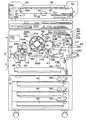
本発明の一実施例である画像処理装置の機構の概要を図1に示す。この実施例は、デジタルフルカラー複写機である。カラー画像読み取り装置(以下、スキャナという)200は、コンタクトガラス202上の原稿180の画像を照明ランプ205、ミラー群204A、204B、204Cなど、およびレンズ206を介してカラーセンサ207に結像して、原稿のカラー画像情報を、例えば、ブルー(以下、Bという)、グリーン(以下、Gという)およびレッド(以下、Rという)の色分解光毎に読み取り、電気的な画像信号に変換する。カラーセンサ207は、この例では、3ラインCCDセンサで構成されており、B、G、Rの画像を色ごとに読み取る。スキャナ200で得たB、G、Rの色分解画像信号強度レベルをもとにして、図示省略された画像処理ユニットにて色変換処理を行い、ブラック(以下、Bkという)、シアン(以下、Cという)、マゼンダ(以下、Mという)およびイエロー(以下、Yという)の記録色情報を含むカラー画像データを得る。 An outline of the mechanism of an image processing apparatus according to an embodiment of the present invention is shown in FIG. This embodiment is a digital full-color copying machine. A color image reading apparatus (hereinafter referred to as a scanner) 200 forms an image of a
このカラー画像データを用い、次に述べるカラー画像記録装置(以下、カラープリンタという)400によって、Bk、C、M、Yの画像を中間転写ベルト上に重ね形成し、そして転写紙に転写する。スキャナ200は、カラープリンタ400の動作とタイミングをとったスキャナースタート信号を受けて、照明ランプ205やミラー群204A、204B、204Cなどからなる照明・ミラー光学系が左矢印方向へ原稿走査し、1回走査毎に1色の画像データを得る。そして、その都度、カラープリンタ400で順次、顕像化しつつ、これらを中間転写ベルト上に重ね合わせて、4色のフルカラー画像を形成する。 Using this color image data, Bk, C, M, and Y images are formed on an intermediate transfer belt by a color image recording apparatus (hereinafter referred to as a color printer) 400 described below, and transferred onto transfer paper. The
カラープリンタ400の、露光手段としての書き込み光学ユニット401は、スキャナ200からのカラー画像データを光信号に変換して、原稿画像に対応した光書き込みを行い、感光体ドラム414に静電潜像を形成する。光書き込み光学ユニット401は、レーザ発光器441、これを発光駆動する発光駆動制御部(図示省略)、ポリゴンミラー443、これを回転駆動する回転用モータ444、fθレンズ442、反射ミラー446などで構成されている。感光体ドラム414は、矢印で示す如く反時計廻りの向きに回転するが、その周りには、感光体クリーニングユニット421、除電ランプ414M、帯電器419、感光体ドラム上の潜像電位を検知する電位センサ414D、リボルバー現像装置420の選択された現像器、現像濃度パターン検知器414P、中間転写ベルト415などが配置されている。 A writing
リボルバー現像装置420は、BK現像器420K、C現像器420C、M現像器420M、Y現像器420Yと、各現像器を矢印で示す如く反時計回りの向きに回転させる、リボルバー回転駆動部(図示省略)などからなる。これら各現像器は、静電潜像を顕像化するために、現像剤の穂を感光体ドラム414の表面に接触させて回転する現像スリーブ420KS、420CS、420MS、420YSと、現像剤を組み上げ・撹拌するために回転する現像パドルなどで構成されている。待機状態では、リボルバー現像装置420はBK現像器420で現像を行う位置にセットされており、コピー動作が開始されると、スキャナ200で所定のタイミングからBK画像データの読み取りがスタートし、この画像データに基づき、レーザ光による光書き込み・潜像形成が始まる。以下、Bk画像データによる静電潜像をBk潜像という。C、M、Yの各画像データについても同じ。このBk潜像の先端部から現像可能とすべく、Bk現像器420Kの現像位置に潜像先端部が到達する前に、現像スリーブ420KSを回転開始して、Bk潜像をBkトナーで現像する。そして、以後、Bk潜像領域の現像動作を続けるが、潜像後端部がBk潜像位置を通過した時点で、速やかに、Bk現像器420Kによる現像位置から次の色の現像器による現像位置まで、リボルバー現像装置420を駆動して回動させる。この回動動作は、少なくとも、次の画像データによる潜像先端部が到達する前に完了させる。 The
像の形成サイクルが開始されると、感光体ドラム414は矢印で示すように反時計回りの向きに回動し、中間転写ベルト415は図示しない駆動モータにより、時計回りの向きに回動する。中間転写ベルト415の回動に伴って、BKトナー像形成、Cトナー像形成、Mトナー像形成およびYトナー像形成が順次行われ、最終的に、BK、C、M、Yの順に中間転写ベルト415上に重ねてトナー像が形成される。BK像の形成は、以下のようにして行われる。すなわち、帯電器419がコロナ放電によって、感光体ドラム414を負電荷で約−700Vに一様に帯電する。つづいて、レーザダイオード441は、Bk信号に基づいてラスタ露光を行う。このようにラスタ像が露光されたとき、当初、一様に荷電された感光体ドラム414の露光された部分については、露光光量に比例する電荷が消失し、静電潜像が形成される。リボルバー現像装置420内のトナーは、フェライトキャリアとの撹拌によって負極性に帯電され、また、本現像装置のBK現像スリーブ420KSは、感光体ドラム414の金属基体層に対して図示しない電源回路によって、負の直流電位と交流とが重畳された電位にバイアスされている。この結果、感光体ドラム414の電荷が残っている部分には、トナーが付着せず、電荷のない部分、つまり、露光された部分にはBkトナーが吸着され、潜像と相似なBk可視像が形成される。中間転写ベルト415は、駆動ローラ415D、転写対向ローラ415T、クリーニング対向ローラ415Cおよび従動ローラ群に張架されており、図示しない駆動モータにより回動駆動される。さて、感光体ドラム414上に形成したBkトナー像は、感光体と接触状態で等速駆動している中間転写ベルト415の表面に、ベルト転写コロナ放電器(以下、ベルト転写部という。)416によって転写される。以下、感光体ドラム414から中間転写ベルト415へのトナー像転写を、ベルト転写と称する。感光体ドラム414上の若干の未転写残留トナーは、感光体ドラム414の再使用に備えて、感光体クリーニングユニット421で清掃される。ここで回収されたトナーは、回収パイプを経由して図示しない排トナータンクに蓄えられる。 When the image forming cycle is started, the
なお、中間転写ベルト415には、感光体ドラム414に順次形成する、Bk、C、M、Yのトナー像を、同一面に順次、位置合わせして、4色重ねのベルト転写画像を形成し、その後、転写紙にコロナ放電転写器にて一括転写を行う。ところで、感光体ドラム414側では、BK画像の形成工程のつぎに、C画像の形成工程に進むが、所定のタイミングから、スキャナ200によるC画像データの読み取りが始まり、その画像データによるレーザ光書き込みで、C潜像の形成を行う。C現像器420Cは、その現像位置に対して、先のBk潜像後端部が通過した後で、かつ、C潜像先端が到達する前に、リボルバー現像装置の回転動作を行い、C潜像をCトナーで現像する。以降、C潜像領域の現像をつづけるが、潜像後端部が通過した時点で、先のBk現像器の場合と同様にリボルバー現像装置420を駆動して、C現像器420Cを送り出し、つぎのM現像器420Mを現像位置に位置させる。この動作もやはり、つぎのM潜像先端部が現像部に到達する前に行う。なお、MおよびYの各像の形成工程については、それぞれの画像データの読み取り、潜像形成、現像の動作が、上述のBk像や、C像の工程に準ずるので、説明は省略する。 The
ベルトクリーニング装置415Uは、入口シール、ゴムブレード、排出コイルおよび、これら入口シールやゴムブレードの接離機構により構成される。1色目のBk画像をベルト転写した後の、2、3、4色目を、画像をベルト転写している間は、ブレード接離機構によって、中間転写ベルト面から入口シール、ゴムブレードなどは離間させておく。 The
紙転写コロナ放電器(以下、紙転写器という。)417は、中間転写ベルト415上の重ねトナー像を転写紙に転写するべく、コロナ放電方式にて、AC+DCまたは、DC成分を転写紙および中間転写ベルトに印加するものである。 A paper transfer corona discharger (hereinafter referred to as a paper transfer unit) 417 is a corona discharge method for transferring the superimposed toner image on the
給紙バンク内の転写紙カセット482には、各種サイズの転写紙が収納されており、指定されたサイズの用紙を収納しているカセットから、給紙コロ483によってレジストローラ対418R方向に給紙・搬送される。なお、符号412B2は、OHP用紙や厚紙などを手差しするための給紙トレイを示している。像形成が開始される時期に、転写紙は前記いずれかの給紙トレイから給送され、レジストローラ対418Rのニップ部にて待機している。そして、紙転写器417に中間転写ベルト415上のトナー像の先端がさしかかるときに、ちょうど転写紙先端がこの像の先端に一致する如くにレジストローラ対418Rが駆動され、紙と像との合わせが行われる。このようにして、転写紙が中間転写ベルト上の色重ね像と重ねられて、正電位につながれた紙転写器417の上を通過する。このとき、コロナ放電電流で転写紙が正電荷で荷電され、トナー画像の殆どが転写紙上に転写される。つづいて、紙転写器417の左側に配置した図示しない除電ブラシによる分離除電器を通過するときに、転写紙は除電され、中間転写ベルト415から剥離されて紙搬送ベルト422に移る。中間転写ベルト面から4色重ねトナー像を一括転写された転写紙は、紙搬送ベルト422で定着器423に搬送され、所定温度にコントロールされた定着ローラ423Aと加圧ローラ423Bのニップ部でトナー像を溶融定着され、排出ロール対424で本体外に送り出され、図示省略のコピートレイに表向きにスタックされる。 The
なお、ベルト転写後の感光体ドラム414は、ブラシローラ、ゴムブレードなどからなる感光体クリーニングユニット421で表面をクリーニングされ、また、除電ランプ414Mで均一除電される。また、転写紙にトナー像を転写した後の中間転写ベルト415は、再び、クリーニングユニット415Uのブレード接離機構でブレードを押圧して表面をクリーニングする。リピートコピーの場合には、スキャナの動作および感光体への画像形成は、1枚目の4色目画像工程にひきつづき、所定のタイミングで2枚目の1色目画像工程に進む。中間転写ベルト415の方は、1枚目の4色重ね画像の転写紙への一括転写工程にひきつづき、表面をベルトクリーニング装置でクリーニングされた領域に、2枚目のBkトナー像がベルト転写されるようにする。その後は、1枚目と同様動作になる。 The surface of the
図1に示すカラー複写機は、パーソナルコンピュータ等のホストから、LAN又はパラレルI/Fを通じてプリントデ−タが与えられるとそれをカラープリンタ400でプリントアウト(画像出力)でき、しかもスキャナ200で読み取った画像データを遠隔のフアクシミリに送信し、受信する画像データもプリントアウトできる複合機能つきのカラー複写機である。この複写機は、構内交換器PBXを介して公衆電話網に接続され、公衆電話網を介して、ファクシミリ交信やサ−ビスセンタの管理サ−バと交信することができる。 The color copier shown in FIG. 1 can be printed out (image output) by a
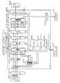
図2に、図1に示す複写機の電気システムの概要を示す。図2はメインコントローラ10を中心に、複写機の制御装置を図示したものである。メインコントローラ10は、複写機全体を制御する。メインコントローラ10には、オペレータに対する表示と、オペレータからの機能設定入力制御を行う操作/表示ボードOPB、エディタ15、スキャナ200およびオプションのADFの制御、原稿画像を画像メモリに書き込む制御、および、画像メモリからの作像を行う制御等を行う、スキャナコントローラ12、プリンタコントローラ16、画像処理ユニット(IPU)40、ならびに、カラープリンタ400内にあって荷電、露光、現像、給紙、転写、定着ならびに転写紙搬送を行う作像エンジンの制御を行うエンジンコントローラ13、等の分散制御装置が接続されている。各分散制御装置とメインコントローラ10は、必要に応じて機械の状態、動作指令のやりとりを行っている。また、紙搬送等に必要なメインモータ、各種クラッチも、メインコントロ−ラ10内の図示しないドライバに接続されている。 FIG. 2 shows an outline of the electric system of the copying machine shown in FIG. FIG. 2 illustrates the control device of the copying machine with the
カラープリンタ400には、給紙トレイからの給紙をはじめとして、感光体414の荷電、レーザ書き込みユニットによる画像露光、現像、転写、定着および排紙を行う機構要素を駆動する電気回路および制御回路、ならびに各種センサ等がある。 The
プリンタコントローラ16は、パソコンなど外部からの画像及びプリント指示するコマンドを解析し、画像データとして、印刷できる状態にビットマップ展開し、メインコントローラ10を介して、プリンタ400を駆動して画像データをプリントアウトする。画像及びコマンドをLAN及びパラレルI/Fを通じて受信し動作するために、LANコントロール19とパラレルI/F18がある。 The
FAXコントローラ17は、フアクシミリ送信指示があるときには、メインコントローラ10を介してスキャナ200およびIPU300を駆動して原稿の画像を読んで、画像データを、通信コントロール20およびPBXを介して、ファクシミリ通信回線に送出する。通信回線からファクシミリの呼びを受け画像データを受信すると、メインコントローラ10を介して、プリンタ400を駆動して画像データをプリントアウトする。 When there is a facsimile transmission instruction, the
図3には、画像処理ユニット(IPU)300の構成を示す。スキャナ200が発生するR、G、B画像データが、インターフェイス351を介してIPU300に与えられる。なお、B又はR単色の記録をBRユニット355が指示する時には、R、G、B画像データの選択と集成が行われるが、このモードの画像記録処理の説明は省略する。IPU300に与えられたR、G、B画像データは、RGBγ補正310で、反射率データ(R、G、Bデータ)から濃度データ(R、G、Bデータ)に変換される。 FIG. 3 shows the configuration of an image processing unit (IPU) 300. R, G, B image data generated by the
原稿認識320が、この濃度R、G、Bデータに基づいて、それらのデータが宛てられる画像領域が文字エッヂ領域(文字や線画のエッジ領域)、網点領域、低線数網点領域か絵柄領域(写真や絵の領域&文字領域でない領域&網点領域でない&網点領域でない)かを判定し、C/P信号およびB/C信号を、RGBフィルタ330、ならびに、インターフェイス353を介してメインコントローラ10に与える。
C/P信号:2ビット信号であり、3が低線数網点領域を示し、2が網点領域を示し、1が文字エッジ領域を示し、0が絵柄領域を示す。
B/C信号:1ビット信号であり、H(「1」)が無彩領域を示し、L(「0」)が有彩領域を示す。Based on the density R, G, and B data, the original recognition 320 determines whether the image area to which the data is addressed is a character edge area (an edge area of a character or line drawing), a halftone dot area, a low-line number halftone dot area, or a pattern. It is determined whether it is a region (photo or picture region & non-character region & halftone dot region & halftone dot region), and the C / P signal and B / C signal are transmitted via the RGB filter 330 and the interface 353. This is given to the
C / P signal: 2-bit signal, 3 indicates a low-line dot area, 2 indicates a dot area, 1 indicates a character edge area, and 0 indicates a picture area.
B / C signal: 1-bit signal, where H (“1”) indicates an achromatic region and L (“0”) indicates a chromatic region.
(原稿認識320)
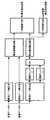
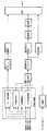
図21に、原稿認識320の機能をブロック区分で示す。
主走査ずれ補正、副走査ずれ補正、認識処理、画像遅延メモリからなり、認識処理部は文字エッジ検出,絵柄検出及び有彩/無彩検出を行って、文字エッジ領域あるいは絵柄領域を表すC/P信号および有彩領域/無彩領域を表すB/C信号を発生し、主走査ずれ補正部では、入力データの主走査のRGB位置ずれを補正して、副走査ずれ補正部では、入力データ副走査のRGB位置ずれを補正する。(Original recognition 320)
FIG. 21 shows the function of the document recognition 320 in block sections.
It consists of main scanning deviation correction, sub-scanning deviation correction, recognition processing, and image delay memory, and the recognition processing unit performs character edge detection, pattern detection, and chromatic / achromatic detection to obtain C / C representing a character edge area or a pattern area. A P signal and a B / C signal representing a chromatic area / achromatic area are generated, the main scanning deviation correction unit corrects the RGB positional deviation of the main scanning of the input data, and the sub scanning deviation correction unit obtains the input data Corrects the RGB position shift in the sub-scanning.
画像遅延メモリでは、認識処理部の認識結果(C/P、B/C)と同期(位置)をあわせて出力する。画像遅延メモリの入力は主走査ずれ補正を行って、副走査のずれ補正をいないのは、主走査の補正は0.5ドット程度の補正に対して、副走査は2,0ドット程度の補正をかけるために、副走査の補正によりRGBデータが、値が変化するために画像遅延メモリには補正を施していない。 In the image delay memory, the recognition result (C / P, B / C) of the recognition processing unit and the synchronization (position) are output together. The input of the image delay memory performs main scanning deviation correction, and does not perform sub-scanning deviation correction. Main scanning correction is about 0.5 dot correction, and sub scanning is about 2,0 dot correction. For this reason, since the RGB data changes in value due to the sub-scan correction, the image delay memory is not corrected.
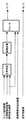
最初に主走査ずれ補正から説明する。主走査ずれ補正は、図29のブロックからなる。
主走査ずれ補正は、仮想サンプリング点算出R、仮想サンプリング点算出B、補正演算R、補正演算Bからなる。ここでの補正は、Gを基準色としてRとBを補正する。ここで、仮想サンプリング点算出Rと仮想サンプリング点算出B、補正Rと補正Bは同一機能なので、Rのみについて説明する。First, the main scanning deviation correction will be described. The main scanning deviation correction includes the blocks shown in FIG.
The main scanning deviation correction includes a virtual sampling point calculation R, a virtual sampling point calculation B, a correction calculation R, and a correction calculation B. In this correction, R and B are corrected using G as a reference color. Here, since virtual sampling point calculation R and virtual sampling point calculation B, and correction R and correction B have the same function, only R will be described.
(仮想サンプリング点算出Rの説明)
Rデータの1ドットに対して+側と−側に1/2のずらしたRデータを補間演算する。この2個(Dm-1, Dm+1,)とずらしていない原データ(Dm)の3個を出力する。実施例では、位置ずれ補正量は0.5ドットであるが光学特性により決まるものである。(Description of virtual sampling point calculation R)
Interpolation calculation is performed on R data shifted by 1/2 on the + side and-side for one dot of R data. Three of these two (Dm-1, Dm + 1,) and the original data (Dm) not shifted are output. In the embodiment, the positional deviation correction amount is 0.5 dots, but is determined by the optical characteristics.
補間方法は、直線補間や3次関数コンボリューション法など何を用いてもよい。3次関数コンボリューション法の説明は、上記特許文献6(特開平9−266536号公報)の図8と段落番号「0030」〜「0031」に記載されている。 Any interpolation method such as linear interpolation or cubic function convolution method may be used. The description of the cubic function convolution method is described in FIG. 8 and paragraph numbers “0030” to “0031” of the above-mentioned Patent Document 6 (Japanese Patent Laid-Open No. 9-266536).
次に補正演算Rについて説明する。
図30に示すように、最初に目標濃度差演算を行う。ここでは、周辺画像データの濃度差を計算する。周辺画像データの参照画素は光学系の特性により決まるがここでは周辺画素左右(主走査)2画素を参照する。注目画素をDnとした時、左右の画素はDn-2、Dn-1、Dn+1、Dn+2とする。以下のすべて条件を満たす画素のR-Gの絶対値を目標濃度差とする。ここで、条件を満たさなければ、目標濃度差なしとして、補正を行わない。
1).RデータのDn-2、Dn-1、Dn、Dn+1、Dn+2の最大値と最小値の差がある閾値以上である。これは、画像データの起伏(エッヂ)があるとのみ補正を行うためである。
2).GデータのDn-2、Dn-1、Dn、Dn+1、Dn+2の最大値と最小値の差がある閾値以上である。これは、画像データの起伏(エッヂ)があるとのみ補正を行うためである。
3).Dn-2、Dn-1、Dn+1、Dn+2、それぞれの画素のR−Gの絶対値を4個を求める。
4).Dn-2、Dn-1、Dn+1、Dn+2のR−Gの絶対値の小さいものから順番にDnのG信号を比較をする。Dn画素のG信号より小さい(濃い)値ならば、目標濃度差とする。
Dn画素のG信号より小さくない時は、その次にR−Gの絶対値の小さいものを順次演算を行う。ここで、目標濃度差が得られなかった時は、Dn画素のR−Gの絶対値とする。
G信号の比較で濃いデータを求めているのは、G信号が輝度信号に近い特性をもっているから、輝度信号で比較しても良い。
濃い画素のデータを使うのは、反射率データの特性で、黒データは、RGB差が非常に少なく、色データはRGB差があるからである。周辺画素より濃度差を決めているので、黒データは理想的にはRGB差は0になる。つまり目標濃度差は色毎に変化する。Next, the correction calculation R will be described.
As shown in FIG. 30, the target density difference calculation is first performed. Here, the density difference of the peripheral image data is calculated. The reference pixels of the peripheral image data are determined by the characteristics of the optical system, but here, reference is made to two peripheral pixel left and right (main scanning) pixels. When the pixel of interest is Dn, the left and right pixels are Dn-2, Dn-1, Dn + 1, and Dn + 2. The absolute value of RG of a pixel that satisfies all the following conditions is set as a target density difference. Here, if the condition is not satisfied, no correction is performed assuming that there is no target density difference.
1). The difference between the maximum value and the minimum value of Dn-2, Dn-1, Dn, Dn + 1, Dn + 2 of the R data is equal to or greater than a threshold value. This is because correction is performed only when there is an undulation (edge) of the image data.
2). The difference between the maximum value and the minimum value of Dn-2, Dn-1, Dn, Dn + 1, Dn + 2 of the G data is equal to or greater than a threshold value. This is because correction is performed only when there is an undulation (edge) of the image data.
3). Dn-2, Dn-1, Dn + 1, Dn + 2, and 4 absolute values of RG of each pixel are obtained.
4). The Dn G signals are compared in order from the smallest absolute value of RG of Dn-2, Dn-1, Dn + 1, and Dn + 2. If the value is smaller (darker) than the G signal of the Dn pixel, the target density difference is determined.
When it is not smaller than the G signal of the Dn pixel, the next one having the smallest absolute value of RG is sequentially calculated. Here, when the target density difference is not obtained, the absolute value of RG of the Dn pixel is used.
The reason why dark data is obtained by comparing the G signal is that the G signal has a characteristic close to that of the luminance signal.
The reason why dark pixel data is used is because of the characteristics of reflectance data, black data has very little RGB difference, and color data has RGB difference. Since the density difference is determined from the peripheral pixels, the black data ideally has an RGB difference of zero. That is, the target density difference changes for each color.
次に、図30に示すように、仮想サンプリング点算出Rで求めた3個のサンプリング点(Dm-1,Dm,Dm+1)と目標濃度差と注目画素のG信号にて、仮想画素演算を行う。ただし、目標濃度差なしの時は、原データであるDmとして仮想画素演算行わない。以下の条件を満たす画素のR-Gの絶対値を目標濃度差とする。
1).3個のサンプリング点(Dm-1,Dm,Dm+1)のそれぞれのR−Gの絶対値を3個求める。
2).Dm-1,Dm,Dm+1のR-Gの絶対値の小さい順に目標濃度差と比較する。R-Gの絶対値が目標濃度以上であれば、目標濃度差とする。目標濃度より小さな値の時は、仮想サンプリング点算出でのサンプル数が少ないために本来補正すべき値より補正を行っている可能性があるため以下の条件をチェックする。
2−1).求めた絶対値の目標濃度差より小さい
2−2).G−Dm-1と、G−Dmとの正負の符号が不一致である。符号が逆になっているということは、サンプリング点が少なくて補正が効き過ぎている。Next, as shown in FIG. 30, the virtual pixel calculation is performed using the three sampling points (Dm−1, Dm, Dm + 1) obtained by the virtual sampling point calculation R, the target density difference, and the G signal of the target pixel. I do. However, when there is no target density difference, the virtual pixel calculation is not performed as the original data Dm. The absolute value of RG of a pixel that satisfies the following conditions is set as a target density difference.
1). Three absolute values of RG for each of the three sampling points (Dm-1, Dm, Dm + 1) are obtained.
2). Comparison is made with the target density difference in ascending order of the absolute value of RG of Dm-1, Dm, and Dm + 1. If the absolute value of RG is greater than or equal to the target density, the target density difference is determined. When the value is smaller than the target density, since the number of samples in the virtual sampling point calculation is small, there is a possibility that correction is performed from the value that should be corrected originally, so the following conditions are checked.
2-1). Less than the target density difference of the absolute value obtained 2-2). The sign of G-Dm-1 does not match that of G-Dm. If the sign is reversed, correction is too effective because there are few sampling points.
上記1、2の条件を満たした時、Gデータに目標濃度差を加えてRデータとして出力する。上記条件を満たさない時は、他のデータの演算を行う。ここで目標濃度差より、大きい値を選択するのは、色文字の彩度低下を防ぐためである。このことにより、黒データの色ずれは黒方向に補正され、色データの彩度低下を防ぐことが可能となる。さらに、基準色を基準に補正を行うので、レンズのRGB毎にMIF特性ばらつきも少なくすることができる。 When the
図31がデータの大小関係で、どのように補正画素(出力画素)になるかを示した例である。目標濃度は、◎+目標濃度差である。 FIG. 31 is an example showing how correction pixels (output pixels) are obtained in relation to the magnitude of data. The target density is ◎ + target density difference.
B信号も同様に補正を行う。
本実施例では、目標濃度差はすべて固定で説明したが、画像データの特性によって濃いところと薄いところで値を変更することも可能である。The B signal is similarly corrected.
In the present embodiment, all target density differences have been described as fixed. However, depending on the characteristics of the image data, it is possible to change the value between dark and light areas.
次に副走査ずれ補正を説明する。副走査ずれ補正も主走査ずれ補正と同様の、第26図のブロックからなる。ここの出力を原稿認識部のみしか反映しないのは、主走査より副走査の方が大きなずれ量を補正するため、画像データの劣化があるためである。言い換えれば、原稿認識部の色判定やACS(カラー原稿判定)に影響が出ないようにしている。 Next, sub-scanning deviation correction will be described. The sub-scanning deviation correction is made up of the blocks shown in FIG. 26, similar to the main-scanning deviation correction. The reason why the output is reflected only by the document recognition unit is that image data is deteriorated because a larger amount of deviation is corrected in the sub-scanning than in the main-scanning. In other words, the color recognition and ACS (color original determination) of the original recognition unit are not affected.
副走査ずれ補正は、仮想サンプリング点算出R、仮想サンプリング点算出B、補正演算R、補正演算Bからなる。ここでの補正は、Gを基準色としてRとBを補正する。ここで、仮想サンプリング点算出Rと仮想サンプリング点算出B、補正Rと補正Bは同一機能なので、Rのみについて説明する。 The sub-scanning deviation correction includes a virtual sampling point calculation R, a virtual sampling point calculation B, a correction calculation R, and a correction calculation B. In this correction, R and B are corrected using G as a reference color. Here, since virtual sampling point calculation R and virtual sampling point calculation B, and correction R and correction B have the same function, only R will be described.
(仮想サンプリング点算出Rの説明)
Rデータの副走査方向に1ラインに対して+側と−側に1/2、1,2のずらしたRデータを補間演算する。この6個(Dm-3 Dm-2, Dm-1, Dm+1, Dm+2, Dm+3,)とずらしていない原データ(Dm)の7個を出力する。実施例では、位置ずれ補正量は2ドットであるが、これは機械振動などの特性値によって決まるものである。ここで、ずれ量を複数求めるのは、細線の密集したところや小さな文字などの細かくエッヂの変化する領域を正しく補正するためである。(Description of virtual sampling point calculation R)
R data shifted by 1/2, 1, or 2 on the + side and-side with respect to one line in the sub-scanning direction of R data is interpolated. The six pieces (Dm-3, Dm-2, Dm-1, Dm + 1, Dm + 2, Dm + 3,) and seven of the original data (Dm) not shifted are output. In the embodiment, the misregistration correction amount is 2 dots, which is determined by a characteristic value such as mechanical vibration. Here, the reason for obtaining a plurality of shift amounts is to correct correctly a region where fine lines change, such as a dense line or a small character.
補間方法は、直線補間や3次関数コンボリューション法など何を用いてもよい。3次関数コンボリューション法の説明は、上記特許文献6(特開平9−266536号公報)の図8と段落番号「0030」〜「0031」に記載されている。 Any interpolation method such as linear interpolation or cubic function convolution method may be used. The description of the cubic function convolution method is described in FIG. 8 and paragraph numbers “0030” to “0031” of the above-mentioned Patent Document 6 (Japanese Patent Laid-Open No. 9-266536).
次に補正演算Rについて説明する。最初に目標濃度差演算を行う。ここでは、周辺画像データの濃度差を計算する。周辺画像データの参照画素は光学系の特性により決まるがここでは周辺画素上下(副走査)2画素を参照する。注目画素をDnとした時、上下のラインはDn-2、Dn-1、Dn+1、Dn+2とする。以下のすべて条件を満たす画素のR-Gの絶対値を目標濃度差とする。ここで、条件を満たさなければ、目標濃度差なしとして、補正を行わない。
1).RデータのDn-2、Dn-1、Dn、Dn+1、Dn+2の最大値と最小値の差がある閾値以上である。これは、画像データの起伏があるとのみ補正を行うためである。
2).GデータのDn-2、Dn-1、Dn、Dn+1、Dn+2の最大値と最小値の差がある閾値以上である。これは、画像データの起伏があるとのみ補正を行うためである。
3).Dn-2、Dn-1、Dn+1、Dn+2、それぞれの画素のR−Gの絶対値を4個を求める。
4).Dn-2、Dn-1、Dn+1、Dn+2のR−Gの絶対値の小さいものから順番にDnのG信号を比較する。Dn画素のG信号より小さい(濃い)値ならば、目標濃度差とする。
Dn画素のG信号より小さくない時は、その次にR−Gの絶対値の小さいものを順次演算を行う。ここで、目標濃度差が得られなかった時は、Dn画素のR−Gの絶対値とする。Next, the correction calculation R will be described. First, the target density difference calculation is performed. Here, the density difference of the peripheral image data is calculated. The reference pixels of the peripheral image data are determined by the characteristics of the optical system, but here reference is made to two pixels above and below (sub-scanning) the peripheral pixels. When the pixel of interest is Dn, the upper and lower lines are Dn-2, Dn-1, Dn + 1, and Dn + 2. The absolute value of RG of a pixel that satisfies all the following conditions is set as a target density difference. Here, if the condition is not satisfied, no correction is performed assuming that there is no target density difference.
1). The difference between the maximum value and the minimum value of Dn-2, Dn-1, Dn, Dn + 1, Dn + 2 of the R data is equal to or greater than a threshold value. This is because correction is performed only when there is undulations in the image data.
2). The difference between the maximum value and the minimum value of Dn-2, Dn-1, Dn, Dn + 1, Dn + 2 of the G data is equal to or greater than a threshold value. This is because correction is performed only when there is undulations in the image data.
3). Dn-2, Dn-1, Dn + 1, Dn + 2, and 4 absolute values of RG of each pixel are obtained.
4). The G signals of Dn are compared in order from the smallest absolute value of RG of Dn-2, Dn-1, Dn + 1, and Dn + 2. If the value is smaller (darker) than the G signal of the Dn pixel, the target density difference is determined.
When it is not smaller than the G signal of the Dn pixel, the next one having the smallest absolute value of RG is sequentially calculated. Here, when the target density difference is not obtained, the absolute value of RG of the Dn pixel is used.
G信号の比較で濃いデータを求めているのは、G信号が輝度信号に近い特性をもっているから、輝度信号で比較しても良い。 The reason why dark data is obtained by comparing the G signal is that the G signal has a characteristic close to that of the luminance signal.
濃い画素のデータを使うのは、反射率データの特性で、黒データは、RGB差が非常に少なく、色データはRGB差があるからである。周辺画素より濃度差を決めているので、黒データは理想的にはRGB差は0になる。つまり目標濃度差は色毎に変化する。 The reason why dark pixel data is used is because of the characteristics of reflectance data, black data has very little RGB difference, and color data has RGB difference. Since the density difference is determined from the peripheral pixels, the black data ideally has an RGB difference of zero. That is, the target density difference changes for each color.
次に、仮想サンプリング点算出Rで求めた7個のサンプリング点(Dm-3 Dm-2, Dm-1, Dm,Dm+1, Dm+2, Dm+3)と目標濃度差と注目画素のG信号にて、仮想画素演算を行う。ただし、目標濃度差なしの時は、原データであるDmとして仮想画素演算行わない。以下の条件を満たす画素のR-Gの絶対値を目標度とする。
1).7個のサンプリング点(Dm-3 Dm-2, Dm-1, Dm,Dm+1, Dm+2, Dm+3)のそれぞれのR−Gの絶対値を7個求める。
2).Dm-1,Dm,Dm+1のR-Gの絶対値の小さい順に目標濃度差と比較する。R-Gの絶対値が目標濃度以上であれば、目標濃度差とする。目標濃度より小さな値の時は、仮想サンプリング点算出でのサンプル数が少ないために本来補正すべき値より補正を行っている可能性があるため以下の条件をチェックする。
2−1).求めた絶対値の目標濃度差より小さい
2−2).G−Dm-1とG−Dmの正負の符号が不一致である。符号が逆になっているということは、サンプリング点が少なくて補正が効き過ぎている。
上記1、2の条件を満たした時、Gデータに目標濃度差を加えてRデータとして出力する。上記条件を満たさない時は、他のデータの演算を行う。
ここで目標濃度差より、大きい値を選択するのは、色文字の彩度低下を防ぐためである。Next, the seven sampling points (Dm-3, Dm-2, Dm-1, Dm, Dm + 1, Dm + 2, Dm + 3) obtained by the virtual sampling point calculation R, the target density difference, and the target pixel Virtual pixel calculation is performed with the G signal. However, when there is no target density difference, the virtual pixel calculation is not performed as the original data Dm. The absolute value of RG of a pixel that satisfies the following conditions is set as the target degree.
1). Seven absolute values of RG for each of the seven sampling points (Dm-3, Dm-2, Dm-1, Dm, Dm + 1, Dm + 2, Dm + 3) are obtained.
2). Comparison is made with the target density difference in ascending order of the absolute value of RG of Dm-1, Dm, and Dm + 1. If the absolute value of RG is greater than or equal to the target density, the target density difference is determined. When the value is smaller than the target density, since the number of samples in the virtual sampling point calculation is small, there is a possibility that correction is performed from the value that should be corrected originally, so the following conditions are checked.
2-1). Less than the target density difference of the absolute value obtained 2-2). The signs of G-Dm-1 and G-Dm do not match. If the sign is reversed, correction is too effective because there are few sampling points.
When the
The reason why the larger value than the target density difference is selected here is to prevent the color character from decreasing in saturation.
このことにより、黒データの色ずれは黒方向に補正され、色データの彩度低下を防ぐことが可能となる。さらに、基準色を基準に補正を行うので、レンズのRGB毎にMIF特性ばらつきも少なくすることができる。 As a result, the color misregistration of the black data is corrected in the black direction, and it becomes possible to prevent a decrease in the saturation of the color data. Furthermore, since the correction is performed based on the reference color, variations in MIF characteristics can be reduced for each RGB of the lens.
図31がデータの大小関係で、どのように補正画素(出力画素)になるかを示した例である。目標濃度は、◎+目標濃度差である。 FIG. 31 is an example showing how correction pixels (output pixels) are obtained in relation to the magnitude of data. The target density is ◎ + target density difference.
B信号も同様に補正を行う。本実施例では、目標濃度差はすべて固定で説明したが、画像データの特性によって濃いところと薄いところで値を変更することも可能である。 The B signal is similarly corrected. In the present embodiment, all target density differences have been described as fixed. However, depending on the characteristics of the image data, it is possible to change the value between dark and light areas.
原稿認識320は、大別すると、フィルタ321,エッジ抽出322,白領域抽出323,網点抽出324,色判定325および総合判定326からなる。なお、ここでは、スキャナ200の読み取り密度が600dpi程度の場合を例として説明する。 The document recognition 320 is roughly divided into a
(フィルタ321)
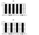
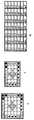
フィルタ321は、主に文字のエッジの抽出ために、スキャナ200が発生するG画像データを補正する。ここで、スキャナ200で読み取ったデータは、レンズなどの性能でボケていることがあるので、エッジ強調フィルタをかける。ただ、ここでは、単純に原稿上の像エッジを強調し、複写機に広く普及している、階調表現のための万線パターンを強調しない必要がある。万線パターンを強調してしまうと、絵柄(万線パターンによる階調表現領域)をエッジとして抽出して、最終的に文字エッジと誤判定する可能性があるので、強調しないようにする必要がある。また、図8に示すように、600dpiの万線パターンAと400dpiの万線パターンBは、繰返し周期が異なるので、同一のフィルタ係数で強調しないようにするのは難しい。そのため、後段の特徴量検出(エッジ抽出、白領域検出)に応じて
2つ係数の演算結果の最大値または、最小値のどちらかを使用する。(Filter 321)
The
なお図8において、主走査方向xの白1ブロック幅とそれに接する黒1ブロック幅との和が、万線ピッチ(定幅:所定数の画素)すなわち万線周期であり、低濃度中間調の時には白ブロック幅が広がり黒ブロック幅が狭くなる。高濃度中間調になるにつれて、白ブロック幅が狭くなり黒ブロック幅が広がる。 In FIG. 8, the sum of the width of one white block in the main scanning direction x and the width of one black block adjacent thereto is a line pitch (constant width: a predetermined number of pixels), that is, a line cycle, and a low density halftone. Sometimes the white block width increases and the black block width decreases. As the density becomes higher, the white block width becomes narrower and the black block width becomes wider.
この実施例では、フィルタ処理321の画素マトリクスを、主走査方向xの画素数7×副走査方向y(スキャナ200の機械的な原稿走査方向)の画素数5として、図4上のフィルタ321のブロックに示すように、各画素宛てに各重み付け係数a1〜a7,b1〜b7,c1〜c7,d1〜d7,e1〜e7を宛てた2組の係数グループ(係数マトリクス)A,Bがある。次の係数グループAは、図8の600dpiの万線パターンAの強調は抑制ししかも文字のエッジを強調するフィルタ処理用の係数であり、係数グループBは、図8の400dpiの万線パターンBの強調は抑制し、しかも文字のエッジを強調するフィルタ処理用の係数である。 In this embodiment, the pixel matrix of the

なお、横方向が主走査方向xの並び、縦方向が副走査方向yの並びである。係数グループA,Bの、グループ内第1行の係数が、図4上のフィルタ321のブロックの係数マトリクスの、第1行の係数a1〜a7であり、係数グループA,Bの第3行の中央の「20」が、フィルタ321のブロックの係数マトリクスの第3行c1〜c7の中央の画素の係数即ち注目画素の係数c4である。係数マトリクスの各係数に、それに宛てられる画素の画像データが表す値を乗算した積(総計7×5=35個)の総和(積和値)が、注目画素(c4が宛てられた画素)の、フィルタ321で処理した画像データ値として、エッジ抽出322および白領域抽出323に与えられる。ここで注目画素とは、現在処理対象の画素であり、それが順次にx方向にそしてy方向に位置が異なるものに更新される。 Note that the horizontal direction is the alignment in the main scanning direction x, and the vertical direction is the alignment in the sub-scanning direction y. The coefficients in the first row of the coefficient groups A and B are the coefficients a1 to a7 in the first row of the coefficient matrix of the block of the
係数グループAは、図8に示す600dpiの万線パターンAの万線ピッチで負の係数(小さい値の係数)が分布しそれらの間に0(やや大きい値の係数)が分布し、そしてエッジ強調のために注目画素には20(極めて大きな係数)が宛てられている。これにより、画像データ(注目画素)が万線パターンAの領域の黒/白間エッジである時には、それにあてて導出される加重平均値(積和値)は、万線パターンAでない文字エッジである時に比べて、かなり低い値になる。 In the coefficient group A, a negative coefficient (small value coefficient) is distributed at the line pitch of the 600 dpi line pattern A shown in FIG. 8, and 0 (slightly large coefficient) is distributed between them, and the edge For emphasis, 20 (very large coefficient) is assigned to the target pixel. As a result, when the image data (target pixel) is the black / white edge of the line pattern A region, the weighted average value (product sum value) derived therefrom is the character edge that is not the line pattern A. Compared to a certain time, the value is considerably lower.
係数グループBは、図8に示す400dpiの万線パターンBの万線ピッチで負の係数(小さい値の係数)が分布しそれらの間に0(やや大きい値の係数)が分布し、そしてエッジ強調のために注目画素には20(極めて大きな係数)が宛てられている。これにより、画像データ(注目画素)が万線パターンBの領域の黒/白間エッジである時には、それにあてて導出される加重平均値(積和値)は、万線パターンBでない文字エッジである時に比べて、かなり低い値になる。 In the coefficient group B, negative coefficients (coefficients having a small value) are distributed at the line pitch of the line pattern B of 400 dpi shown in FIG. For emphasis, 20 (very large coefficient) is assigned to the target pixel. As a result, when the image data (target pixel) is the black / white edge of the line pattern B region, the weighted average value (product sum value) derived to that is the character edge that is not the line pattern B. Compared to a certain time, the value is considerably lower.
なお、フィルタ321では、係数グループAと係数グループBの演算を行い、エッジ抽出322に、(演算結果の最小値/16+注目画素)を出力して、白領域抽出323には、(演算結果の最大値/16+注目画素)を出力する。 The
係数A,Bは、ラプラシアンなので所定の係数(16)で割って、注目画素に足し合わせて補正をおこなう エッジ抽出322に、演算結果の最小値するのは、文字の構造が万線形状をしている場合に、白レベルが十分に抽出できないことがあるのを避けるためである。 The coefficients A and B are Laplacian, and are divided by a predetermined coefficient (16) and added to the target pixel for correction. In the
白領域抽出323には、演算結果の最大値を出力するのは、絵柄が万線パターンの構造の時(例えば複写機の出力)により絵柄をなりやすいように、最大値を出力する。このことにより、エッジ抽出ではよりエッヂと拾いやすくして、白領域検出ではより絵柄として拾いやすくしている。本実施例では、2つ係数を例に取って説明したが、3つ以上の係数でも同様の効果が得られる。 The maximum value of the calculation result is output to the
図4には、エッジ処理にG画像データを参照する態様を示すが、Gデータに限らず、輝度データであってもよい。濃いか薄いかを表現する信号なら適応可能である。 Although FIG. 4 shows a mode in which G image data is referred to for edge processing, the present invention is not limited to G data and may be luminance data. Any signal expressing dark or light can be applied.
(エッジ抽出322)
文字領域は、高レベル濃度の画素と低レベル濃度の画素(以下、黒画素、白画素と呼ぶ)が多く、かつ、エッジ部分では、これらの黒画素及び白画素が連続している。エッジ抽出322は、このような黒画素及び白画素それぞれの連続性に基づいて文字エッジを検出する。(Edge extraction 322)
In the character region, there are many high-level density pixels and low-level density pixels (hereinafter referred to as black pixels and white pixels), and these black pixels and white pixels are continuous in the edge portion. The
(3値化322a)
先ず、3値化322aで、2種の閾値TH1およびTH2を用いて、フィルタ321が文字エッジ強調のフィルタ処理をしたG画像データ(エッジ抽出322の入力データ)を3値化する。閾値TH1およびTH2は、例えば、画像データが0から255までの256階調(0=白)を表す場合、例えばTH1=20、TH2=80に設定する。3値化322aでは、入力データ<TH1であると、該データが宛てられる画素を白画素と、TH1≦入力データ<TH2であると中間調画素と、TH2≦入力データであると黒画素と、表す3値化データに入力データを変換する。(Ternization 322a)
First, in the ternarization 322a, the G image data (input data of the edge extraction 322) subjected to the filter processing for character edge enhancement by the
(黒画素連続検出322b,白画素連続検出322c)
黒画素連続検出322bおよび白画素連続検出322cが、3値化データに基づいて、黒画素が連続する箇所および白画素が連続する箇所を、それぞれパターンマッチングにより検出する。このパターンマッチングには、本実施例では、図9に示す3×3画素マトリクスのパターンBPa〜BPdおよびWPa〜WPdを用いる。図9に示すパターンにおいて、黒丸は上述の黒画素であることを示し、白丸は上述の白画素であることを示し、いずれの丸印もない空白画素は、黒画素,中間調画素,白画素のいずれであるか問わないものである。3×3画素マトリクスの中心の画素が注目画素である。(Black pixel continuous detection 322b, white pixel
The black pixel continuous detection 322b and the white pixel
黒画素連続検出322bは、3値化データの内容の分布が、図9に示す黒画素分布パターンBPa〜BPdのいずれかにマッチングすると、その時の注目画素を「黒連続画素」としてそれをあらわすデータを該注目画素に与える。同様に、白画素連続検出322cは、図9に示す白画素分布パターンWPa〜WPdのいずれかにマッチングすると、その時の注目画素を「白連続画素」としてそれをあらわすデータを該注目画素に与える。 The black pixel continuous detection 322b is data indicating that the target pixel at that time is “black continuous pixel” when the distribution of the content of the ternary data matches any of the black pixel distribution patterns BPa to BPd shown in FIG. Is given to the target pixel. Similarly, when the white pixel
(近傍画素検出322d)
次の近傍画素検出322dは、黒画素連続検出322bおよび白画素連続検出322cの検出結果について、この近傍画素検出322dでの注目画素の近傍に黒連続画素又は白連続画素があるか否かを調べることにより、該注目画素が、エッジ領域と非エッジ領域のいずれにあるかを判定する。より具体的に述べれば、本実施例にあっては、5×5画素マトリクスのブロックで、その内部に黒連続画素と白連続画素がそれぞれ1つ以上存在するときに、そのブロックをエッジ領域と判定し、そうでないときに、そのブロックを非エッジ領域と判定する。(Neighboring pixel detection 322d)
The next neighboring pixel detection 322d checks whether there are black continuous pixels or white continuous pixels in the vicinity of the target pixel in the neighboring pixel detection 322d with respect to the detection results of the black pixel continuous detection 322b and the white pixel
(孤立点除去322e)
さらに、文字エッジは連続して存在するので、孤立点除去322eにて孤立しているエッジを非エッジ領域に補正する。そして、エッジ領域と判定した画素に対して”1”(エッジ領域)なるedge信号を出力し、非エッジ領域と判定した画素に対して”0”(非エッジ領域)なるedge信号を出力する。(Isolated point removal 322e)
Furthermore, since the character edges exist continuously, the isolated edges are corrected to the non-edge regions by the isolated point removal 322e. Then, an edge signal “1” (edge region) is output to a pixel determined to be an edge region, and an edge signal “0” (non-edge region) is output to a pixel determined to be a non-edge region.
(白領域抽出323)
白領域抽出323は、2値化323a,RGB白抽出323b,白判定323c,白パターンマッチング323d,黒判定323e,黒パターンマッチング323fおよび白補正323gからなる。(White area extraction 323)
The
(2値化323a)
2値化323aは、フィルタ321の画像濃度データ(G画像データ)のエッジ強調出力を、閾値thwsbで2値化して、白パターンマッチング323d(の処理を表す図5のステップ7)が参照する白データの生成のための2値化白判定信号を発生する。なお、エッジ強調出力は、この実施例では0から255の256階調であり、0が濃度の無い白であり、閾値thwsbの一例は、50であって、エッジ強調出力の値がthwsb=50より小さければ、2値化323aが「2値化白」と判定し2値化白判定信号「1」を発生する。エッジ強調出力の値がthwsb=50以上のときは2値化白判定信号「0」を発生する。(Binarization 323a)
The binarization 323a binarizes the edge emphasis output of the image density data (G image data) of the
(RGB白抽出323b)
RGB白抽出323bは、1.)RGB白地検出,2.)色地検出および3.)谷白画素検出を行って、画像データが白領域かを判定する。(RGB white extraction 323b)
RGB white extraction 323b is: ) RGB white background detection, 2. 2.) Color ground detection and ) Valley white pixel detection is performed to determine whether the image data is a white area.
1.)RGB白地検出
該RGB白地検出では、R,G,B画像データで白地領域を検出することにより、白背景分離の動作をアクティブにする。すなわち白背景分離の処理を起動する。具体的には、図10のパターンWBPに示すように、3×3画素マトリックスのR,G,B画像データのすべてが閾値thwssより小さければ、注目画素(3×3画素マトリックスの中心画素)が白領域と判定して白パターンマッチング323d(の処理を表す図5のステップ3が参照する白地判定信号)をアクティブ(「1」)にする。これは、ある程度の広がりの白画素領域があるかを検出するものである。なお、R,G,B画像データのそれぞれも、この実施例では0から255の256階調であり、0が濃度の無い基底レベルであり、閾値thwss<thwsbであって、thwssの一例は、40であって、R,G,B画像データのすべてがthwss=40より小さいと、「白地」と判定し白地判定信号「1」を発生する。R,G,B画像データのいずれかがthwss=40以上のときは白地判定信号「0」を発生する。1. ) RGB White Background Detection In the RGB white background detection, the white background separation operation is activated by detecting the white background area from the R, G, B image data. That is, the white background separation process is started. Specifically, as shown in the pattern WBP of FIG. 10, if all of the R, G, B image data of the 3 × 3 pixel matrix is smaller than the threshold thwss, the target pixel (the central pixel of the 3 × 3 pixel matrix) is determined. It is determined as a white area and white pattern matching 323d (a white background determination signal referred to in
2.)色地検出
薄い色を白背景と判定しないようにするために、色地を検出する。
A.ここでは先ず、注目画素を中心とする5×5画素マトリックスの各画素の符号を、図11のパターンMPpに示すものとすると、注目画素となる中心画素c3(MCa〜MCdの×印画素)のRGB差(1画素宛てのR,G,B画像データの最大値と最小値との差)が閾値thcより大きいと色画素判定信号aを「1」(色画素)とし、閾値thc以下のときは「0」(白黒画素)とする。
B.注目画素の片側の周辺画素群△(図11のMCa〜MCdの中)のいずれかの画素のR,G,B画像データがすべて閾値thwc以下であると一方側白判定信号bを「1」(白画素)とし、閾値thwcを超えるときは「0」(非白画素)とする。閾値thwcは例えば20である。
C.注目画素の他方側の周辺画素群□(図11のMCa〜MCdの中)のいずれかの画素のR,G,B画像データがすべて閾値thwc以下であると他方側白判定信号cを「1」(白画素)とし、閾値thwcを超えるときは「0」(非白画素)とする。
D.図11のパターンMCa〜MCdのいずれかにおいて、a AND (bとcのエクスクルーシブノア)=「1」が成立すると、すなわち、a=「1」(注目画素が色画素)、かつ、bとcが一致(注目画素の両側ともに白画素、または、両側ともに非白画素)のとき、注目画素宛ての、色地判定信号dを「1」(色地)とする。この色地判定信号dは、白パターンマッチング323d(の処理を表す図5のステップ6)で、参照される。2. ) Color background detection Color background is detected so that a light color is not judged as a white background.
A. Here, first, assuming that the sign of each pixel of the 5 × 5 pixel matrix centered on the target pixel is shown in the pattern MPp of FIG. 11, the center pixel c3 (the X mark pixels of MCa to MCd) serving as the target pixel. When the RGB difference (difference between the maximum value and the minimum value of R, G, B image data addressed to one pixel) is larger than the threshold value thc, the color pixel determination signal a is set to “1” (color pixel), and is equal to or less than the threshold value thc. Is “0” (monochrome pixel).
B. When the R, G, B image data of any pixel in the peripheral pixel group Δ (in MCa to MCd in FIG. 11) on one side of the target pixel is all equal to or less than the threshold thwc, the one-side white determination signal b is set to “1”. (White pixel), and “0” (non-white pixel) when the threshold value thwc is exceeded. The threshold thwc is 20, for example.
C. If the R, G, B image data of any pixel in the peripheral pixel group □ (in MCa to MCd in FIG. 11) on the other side of the target pixel is all equal to or less than the threshold thwc, the other side white determination signal c is set to “1 ”(White pixel), and“ 0 ”(non-white pixel) when the threshold value thwc is exceeded.
D. If any one of the patterns MCa to MCd in FIG. 11 satisfies a AND (exclusive NOR of b and c) = “1”, that is, a = “1” (the pixel of interest is a color pixel), and b and c Are identical (white pixels on both sides of the target pixel or non-white pixels on both sides), the color gamut determination signal d addressed to the target pixel is set to “1” (color background). This color ground determination signal d is referred to in white pattern matching 323d (
上述のパターンマッチングA.〜D.を行うのは、黒文字のまわりがRGB読み取り位置ずれでわずかながらに色付きになるときそこを色と拾わないためである。黒文字のまわりの色付きの位置では、(bとcのエクスクルーシブノア)が「0」(注目画素の両側の一方が白画素、他方が非白画素)となり、この場合は、色地判定信号d=「0」(非色地)となる。加えて、注目画素が、周辺を白地で囲まれた色画素のときには、色地判定信号d=「1」(色地)となり、線が込み入ったところでも、薄い色画素を色地として検出することができる。すなわち、線が込み入ったところでは、本来白いところが完全に白に読み取られないが、上記処理A.でRGB差が小さいと色画素と判定しないので、閾値thwcを、濃度を見るべき白地よりも厳しく設定して(たとえばthwss=40,thwsb=50に対し、thwc=20)、B.〜D.の処理で白背景か否を厳密にチェックして薄い色画素を色地として正確に検出することができる。 Pattern matching as described above ~ D. This is because when the surroundings of the black characters are slightly colored due to the RGB reading position shift, they are not picked up as colors. At a colored position around the black character, (exclusive NOR of b and c) is “0” (one pixel on both sides of the target pixel is a white pixel and the other is a non-white pixel). In this case, the color gamut determination signal d = “0” (non-colored background). In addition, when the pixel of interest is a color pixel whose periphery is surrounded by a white background, the color background determination signal d = “1” (color background), and even when the line is intricate, a light color pixel is detected as the color background. be able to. That is, when the line is intricate, the originally white portion is not completely read as white. If the RGB difference is small, the pixel is not determined as a color pixel. Therefore, the threshold thwc is set to be stricter than the white background where the density is to be viewed (for example, thwsc = 20 for thwss = 40, thwsb = 50). ~ D. In this process, it is possible to accurately check whether the background is a white background and accurately detect a light color pixel as a color background.
3.)谷白画素検出
次に、谷白画素検出では、上記RGB白地検出で検出できない小さな白領域の谷白画素を、図10に示すG画像データの5×5画素マトリクス分布RDPaおよびRDPbに基づいて検出する。具体的には、5×5画素マトリクス分布RDPaに基づいて、miny=min(G[1][2],G[1][3],G[1][4],G[5][2],G[5][3],G[5][4])を算出する。即ち、図10に示す5×5画素マトリクス分布RDPaの、黒丸を付した画素群の中の最低濃度minyを摘出する。そして、maxy=max(G[3][2],G[3][3],G[3][4])を算出する。即ち、図10に示す5×5画素マトリクス分布RDPaの、白丸を付した画素群の中の最高濃度maxyを摘出する。3. ) Valley White Pixel Detection Next, in the valley white pixel detection, valley white pixels in a small white area that cannot be detected by the above RGB white background detection are based on the 5 × 5 pixel matrix distributions RDPa and RDPb of the G image data shown in FIG. To detect. Specifically, based on the 5 × 5 pixel matrix distribution RDPa, miny = min (G [1] [2], G [1] [3], G [1] [4], G [5] [2 ], G [5] [3], G [5] [4]). That is, the minimum density miny in the pixel group with black circles in the 5 × 5 pixel matrix distribution RDPa shown in FIG. 10 is extracted. Then, maxy = max (G [3] [2], G [3] [3], G [3] [4]) is calculated. That is, the highest density maxy in the pixel group with white circles in the 5 × 5 pixel matrix distribution RDPa shown in FIG. 10 is extracted.
次に、mint=min(G[2][1],G[3][1],G[4][1],G[2][5],G[3][5],G[4][5])を算出する。即ち、図10に示すもう1つの5×5画素マトリクス分布RDPbの、黒丸を付した画素群の中の最低濃度mintを摘出する。そして、maxt=max(G[2][3],G[3][3],G[4][3])を算出する。即ち、図10に示す5×5画素マトリクス分布RDPbの、白丸を付した画素群の中の最高濃度maxtを摘出する。ここで、min( )は最小値を検出する関数である。max( )は、最大値を検出する関数である。 Next, mint = min (G [2] [1], G [3] [1], G [4] [1], G [2] [5], G [3] [5], G [4 ] [5]) is calculated. That is, the lowest density mint in the pixel group with a black circle in another 5 × 5 pixel matrix distribution RDPb shown in FIG. 10 is extracted. Then, maxt = max (G [2] [3], G [3] [3], G [4] [3]) is calculated. That is, the highest density maxt in the pixel group with white circles in the 5 × 5 pixel matrix distribution RDPb shown in FIG. 10 is extracted. Here, min () is a function for detecting the minimum value. max () is a function for detecting the maximum value.
次に、 OUT=((miny-maxy) > 0) # ((mint-maxt) > 0)を算出する。即ち、(miny-maxy)と(mint-maxt)のうち、正値であって大きいほうの値を谷検出値OUTとし、このOUTの値がある閾値以上であると、注目画素(RDPaまたはRDPbの中心画素)を谷白画素と検出する。このように画像の谷状態を検出して、1.)RGB白地検出では、検出しにくいところを補う。 Next, OUT = ((miny-maxy)> 0) # ((mint-maxt)> 0) is calculated. That is, of (miny-maxy) and (mint-maxt), the larger positive value is defined as a valley detection value OUT, and if the value of OUT is equal to or greater than a certain threshold, the target pixel (RDPa or RDPb Are detected as valley white pixels. In this way, the valley state of the image is detected. ) RGB white background detection compensates for difficult detection.
(白判定323c)
ここでは、白判定にもちいる状態変数MS,SS[I]の更新を行う。その内容を図5に示す。ここで、状態変数MSは処理対象ライン(注目ライン)の画素宛てのもの、状態変数SS[I]は処理対象ラインの1ライン前(処理済ライン)の画素宛てのものであり、いずれも白地の白の程度を表す4bitの白地情報であり、図5の処理によって生成されるものである。状態変数MSおよびSS[I]が表す値の最高値は15に定めており、これが最も白い程度を意味し、最低値は0である。すなわち状態変数MSおよびSS[I]は、白の程度を示すデータであり、それが表す値が大きいほど、強い白を意味する。複写動作開始時に、状態変数MSおよびSS[I]は共に0に初期化される。(White determination 323c)
Here, the state variables MS and SS [I] used for white determination are updated. The contents are shown in FIG. Here, the state variable MS is addressed to the pixel of the processing target line (target line), and the state variable SS [I] is addressed to the pixel one line before the processing target line (processed line). This is 4-bit white background information representing the degree of white, and is generated by the processing of FIG. The maximum value represented by the state variables MS and SS [I] is set to 15, which means the whitest degree, and the minimum value is 0. That is, the state variables MS and SS [I] are data indicating the degree of white, and the larger the value represented, the stronger the white. At the start of the copying operation, the state variables MS and SS [I] are both initialized to 0.
図5の処理においてはまず、処理対象である注目画素の1ライン前の状態変数すなわち白地情報SS[I]と注目画素の同一ライン上の1画素前の画素(先行画素:処理済画素)の状態変数すなわち白地情報MSとを比較して(ステップ1)、1ライン前の白地情報SS[I]の方が大きければ、それを注目画素の仮の白地情報MSとする(ステップ2)が、そうでないと先行画素の状態変数MSを、注目画素の仮の白地情報MSとする。これは、周辺画素の白地情報の、より白に近い情報を選択することを意味する。 In the process of FIG. 5, first, the state variable of the target pixel one line before the processing target, that is, the white background information SS [I] and the pixel of the previous pixel on the same line as the target pixel (previous pixel: processed pixel). The state variable, that is, the white background information MS is compared (step 1). If the white background information SS [I] one line before is larger, this is used as the temporary white background information MS of the target pixel (step 2). Otherwise, the state variable MS of the preceding pixel is set as the temporary white background information MS of the target pixel. This means that information closer to white of the white background information of the peripheral pixels is selected.
複写動作を開始してから、前記1.)RGB白地検出で白領域すなわち白地を検出すると〔前記1.〕RGB白地検出の出力である白地判定信号=「1」〕、注目画素の1ライン前の画素の白地情報SS[I]を15に更新し(ステップ3,4)、注目画素の白地情報MSも15とする(ステップ5)。そして、注目画素の白地情報MSは、図12に示すラインメモリLMPの、現ライン(注目ライン)用のラインメモリの注目画素の主走査位置(F)に書き込み、1ライン前の画素宛ての白地情報SS[I]は、図12に示すラインメモリLMPの、前1ライン用のラインメモリの、注目画素の主走査位置(F)に書き込む(ステップ3,4,5)。次に、1ライン前の画素宛ての白地情報SS[I]を、1ライン前の画素に、次のように、伝搬させる(ステップ14〜17)。なお、[I]は注目画素の主走査位置を意味し、[I−1]は主走査方向xでそれより1画素前の画素(注目画素の直前の画素)の位置を意味する。 After starting the copying operation, the above 1. ) When a white area, that is, a white background is detected by RGB white background detection [1. The white background determination signal = “1”, which is the output of RGB white background detection, and the white background information SS [I] of the pixel one line before the target pixel is updated to 15 (
SS[I−1]<SS[I]−1の時、SS[I−1]=SS[I]−1をラインメモリにセットする(ステップ14,15)。即ち、注目画素より1ライン前のラインにおいて、主走査方向で注目画素の位置(F)より1画素前(E)の白地情報SS[I−1]よりも注目画素の位置(F)の白地情報SS[I]から1を減算した値「SS[I]−1」のほうが大きい(白程度が強い)と、1ライン前のライン上の注目画素の位置(F)より1画素前の画素(E)宛ての白地情報SS[I−1]を、注目画素の位置(F)の白地情報SS[I]より1だけ白強度を下げた値に更新する。 When SS [I-1] <SS [I] -1, SS [I-1] = SS [I] -1 is set in the line memory (
次に、SS[I−2]<SS[I]−2の時、SS[I−2]=SS[I]−2をラインメモリにセットする(ステップ16,17−14,15);
次に、SS[I−3]<SS[I]−3の時、SS[I−3]=SS[I]−3をラインメモリにセットする(ステップ16,17−14,15)。Next, when SS [I-2] <SS [I] -2, SS [I-2] = SS [I] -2 is set in the line memory (steps 16, 17-14, 15);
Next, when SS [I-3] <SS [I] -3, SS [I-3] = SS [I] -3 is set in the line memory (steps 16, 17-14, 15).
以下同様にして、最後に、SS[I−15]<SS[I]−15の時、SS[I−15]=SS[I]−15をラインメモリにセットする(ステップ16,17−14,15)。これらの白地情報SS[I]の値の下限値MINは0であり、0未満になるときには、0にとどめる。これは後述のステップ13においても同様である。 In the same manner, finally, when SS [I-15] <SS [I] -15, SS [I-15] = SS [I] -15 is set in the line memory (
これらのステップ14〜17の処理により、1ライン前かつ注目画素の主走査位置より前の白地情報SSが、注目画素の白地情報MSを、それから主走査方向xの1画素の位置ずれにつき1の低減率で下げた値に更新され、注目画素の白地情報が1ライン前の主走査方向xで主走査の後方に、前記低減率で伝搬する(白伝搬処理)。但しこれは、1ライン前の白地情報のほうが小さい値である場合である。例えば1ライン前の画素が、前記1.)RGB白地検出で白地(白領域)と検出したものであるときにはそれの白地情報は15であって最高値であるので書換えは行われない。 By the processing of these
注目画素を更新してそれが白地でないものになると〔前記1.)RGB白地検出の出力である白地判定信号=「0」〕、ステップ3からステップ6以下に進み、注目画素が、色地〔前記2.)色地検出の出力である色地判定信号d=「1」〕でなく(非色地であり)、2値化白〔前記2値化323aの出力である2値化白判定信号=「1」〕であり、しかも、ステップ1,2で仮に定めた注目画素の状態変数すなわち白地情報MSが閾値thw1(例えば13)以上、である時に、注目画素宛ての白地情報MSを+1する(ステップ6〜10)。すなわち、1だけ白程度が強い値に更新する。白地情報MSの最高値maxは15に定めており、15を超える時には15にとどめる(ステップ9,10)。この経路を進んできたときにも、前述の、ステップ5および14〜17を実行する。すなわち、白伝搬処理を行う。 When the pixel of interest is updated and it becomes a non-white background [1. ) RGB white background detection output white background determination signal = “0”], the process proceeds from
注目画素が非色地かつ2値化白ではあるが、白地情報MSがthw1(たとえば7)未満、thw2(例えば1)以上、かつ、谷白画素である時には、状態変数MSをそのままの値に保持する(ステップ8,11,12)。この経路を進んできたときにも、前述の、ステップ5および14〜17を実行する。すなわち、白伝搬処理を行う。 When the target pixel is non-colored and binary white, but the white background information MS is less than thw1 (for example, 7), thw2 (for example, 1) or more, and is a valley white pixel, the state variable MS is set to the value as it is. Hold (
上記条件のいずれにも一致しないとき、すなわち注目画素が色地又は非2値化白のときは、注目画素の白地情報MSを−1する(ステップ13)。すなわち白程度が1だけ弱い白地情報に更新する。白地情報MSの最低値MINは0であり、0未満になる時には0にとどめる。この経路を進んできたときにも、前述の、ステップ5および14〜17を実行する。すなわち、白伝搬処理を行う。 If none of the above conditions is met, that is, if the pixel of interest is a color background or non-binary white, the white background information MS of the pixel of interest is decremented by 1 (step 13). That is, it is updated to white background information whose white level is weak by one. The minimum value MIN of the white background information MS is 0, and is kept at 0 when it is less than 0. Even when the route has been reached,
以上の白地情報MSの生成により、ラインメモリLMP上において、状態変数(白地情報)MSを介して周辺画素に白情報を伝搬させることができる。この白地情報MSの生成は前述のように、色データ(R,G,B画像データのすべて)が閾値thwss=40より小さいとき白地と表すRGB白地判定信号に基づいた、図5のステップ3−4−5−14〜17の系統の、色対応の白地情報MSの生成を含み、しかも、濃度データ(G画像データ)のエッジ強調出力(フィルタ321の出力)が、閾値thwsb=50より小さいとき白地と2値化白判定信号に基づいた、図5のステップ7〜13−5−14〜17の系統の、濃度対応の白地情報MSの生成を含む。 By generating the white background information MS as described above, the white information can be propagated to the peripheral pixels via the state variable (white background information) MS on the line memory LMP. As described above, the white background information MS is generated based on the RGB white background determination signal that represents the white background when the color data (all of the R, G, and B image data) is smaller than the threshold thwss = 40. When generation of color-corresponding white background information MS of the system of 4-5-14 to 17 is included, and the edge enhancement output (output of the filter 321) of the density data (G image data) is smaller than the threshold thwsb = 50 This includes the generation of density-corresponding white background information MS for the system in
この白判定323cは、まずRGB白抽出323bの中の1.)RGB白地検出で、白領域を検出するまで、すなわち前記1.)RGB白地検出が白地判定信号「1」を発生しこれに対応して色対応の白地情報MSの生成(ステップ3−4−5−14〜17)を開始するまで、は動作(ステップ4の実行)をしない。これは、白領域との判定が得られない領域を、フィルタ321のエッジ強調処理後G画像データの後述する白パターンマッチングにて白画素(白ブロック)と誤判定することを防ぐためである。 The white determination 323c is performed by first selecting 1. of the RGB white extraction 323b. ) RGB white background detection until a white area is detected, i.e. ) Until the RGB white background detection generates the white background determination signal “1” and the generation of the color-corresponding white background information MS (steps 3-4-5-14 to 17) starts correspondingly, the operation (step 4) Do not execute. This is to prevent an area that cannot be determined as a white area from being erroneously determined as a white pixel (white block) in white pattern matching (to be described later) of the G image data after edge enhancement processing by the
薄い色地上の文字にエッジ強調フィルタ321をかけると、文字周辺のデータが本来の画像データ(色地)より、レベルの低い値(白)となるので、フィルタ321のエッジ強調処理後のデータで白パターンマッチングをすると、すなわち濃度対応の白地情報MSの生成(ステップ7〜13−5−14〜17)のみに基づいて白領域判定をすると、色地上の文字周辺を白地と誤判定しやすいが、上述の色対応の白地情報MSの生成(ステップ3−4−5−14〜17)によって白領域との判定が得られる領域に後述する、白画素(白ブロック)を判定するための白パターンマッチングを適用するように白地情報MSを最高値とし、ステップ3で白地でないときには、更にステップ6以下で詳細に白地条件をチェックして白パターンマッチングを適用するか否を決定するための1つのパラメータである白地情報MSを調整するので、フィルタ321のエッジ強調処理後G画像データの後述する白パターンマッチングにて白画素(白ブロック)と誤判定することを防いでいる。 When the
例えば、色画素の可能性が高いときには、白地情報MSを下げ(ステップ13)、色画素の疑いもありえるときには白地情報MSをホールド(変更無し)にして(ステップ11〜13)、後述する白パターンマッチングにて白画素(白ブロック)と誤判定することを防いで、文字周辺のデータが本来の画像データ(色地)より、レベルの低い値(白)となるのを防止している。 For example, when the possibility of a color pixel is high, the white background information MS is lowered (step 13), and when there is a suspicion of a color pixel, the white background information MS is held (no change) (
文字が密なところは上述の処理(ステップ3〜5,6〜10および14〜17)によって白地情報MSを更新し伝搬させるので、密な文字領域が絵柄と誤判定される可能性が低減する。また、込み入った文字(例えば、「書」)などの文字の中は、1.)RGB白地検出で白検出ができない場合があるが、そのときに3.)谷白画素検出にて、白と検出し、白地情報MSを、ステップ12のYES出力がステップ5に直進する経路でホールドして、白地傾向にとどめるので、込み入った文字の中が絵柄と誤判定される可能性が低減する。 When the character is dense, the white background information MS is updated and propagated by the above-described processing (
また、先に触れたように、注目画素が、周辺を白地で囲まれた色画素のときには、前記2.)色地検出の出力である色地判定信号d=「1」(色地)となり、線が込み入ったところでも、薄い色画素を色地として検出することができ、注目画素周辺が白かを見る閾値thwcを低く設定して(thwc=20)、薄い色画素(注目画素)の周辺が白背景か否を厳密にチェックして薄い色画素を色地として検出することができるので、込み入った文字の中が絵柄と誤判定される可能性を更に低減することができる。 As described above, when the pixel of interest is a color pixel surrounded by a white background, 2. ) Color gamut detection signal d = “1” (color gamut), which is an output of color gamut detection, can detect a thin color pixel as a color gamut even where a line is intricate, and determine whether the periphery of the target pixel is white. Since the threshold value thwc for viewing is set low (thwc = 20), it is possible to detect a thin color pixel as a color background by strictly checking whether or not the periphery of a light color pixel (target pixel) is a white background. It is possible to further reduce the possibility that the character is erroneously determined as a picture.
上述のように、薄い色画素を色地としてより厳密に検出できることにより、色地と検出したときには図5のステップ6からステップ13に進んで、状態変数MSを下げて色地を白と判定する可能性を低減できるのに加えて、ステップ3で参照する白地判定信号を生成する時の閾値thwss(たとえば40)に対して、ステップ7で参照する2値化白判定信号を生成する時の閾値thwsb(例えば50)を大きい値として、色地と判定しなかつた場合(ステップ6:NO)には、前記2値化323aで白と見なす確率を高くして、図5のステップ7から10に進んで状態変数MSを上げて白領域と判定する可能性を高くしている。 As described above, since a light color pixel can be detected more precisely as a color background, the process proceeds from
すなわち、前記1.)RGB白地検出で閾値thwss=40で、白と判定する確率が低い厳しい白判定を行って、そこで白地と判定すると、図5のステップ3から4以下の処理により、状態変数MSを上げて文字背景を白と判定する可能性を高くしている。該厳しい白判定で白地との判定が出なかったときには、では逆に色地であるかの、薄い色画素も色地として検出する信頼性が高い厳しい色地判定、すなわち前記2.)色地検出、の結果を参照し、それが色地との判定にならないときには、もう一度、今度は白と判定する確率が高い閾値thwsb=50の甘い白判定、すなわち前記2値化323a、を参照してそれが白の判定であると、状態変数MSを上げて文字背景を白と判定する可能性を高くしている(ステップ7〜10)。この処理(ステップ6〜10)があるので、色地と検出される薄い色画素よりも更に薄い背景濃度ムラ、例えば裏映りのような原稿の地にムラがある場合に、原稿の細かい地ムラに連動して状態変数MSが2値的に大きく変化するのが抑制され、つぎの白パターンマッチング323dでの白画素か否かの判定が走査方向に細かく変動するのが抑制される。その結果、背景が薄い色地のときに、裏映りのような原稿の細かい地ムラに連動して細かい色抜け(白背景)が現れることがなくなる。 That is, the above 1. ) RGB white background detection with a threshold thwss = 40, and a strict white determination with a low probability of determining white is performed. If the white background is determined there, the state variable MS is increased by the processing from
(白パターンマッチング323d)
注目画素を中心とする5×5画素単位のブロックで連続した白画素が存在するか否かで、背景が白かを判断する。そのために、注目画素に関して、次式が満たされる時に、注目画素を白画素と仮に定めて、白パターンマッチングを行う。
(非色画素&(白地情報MS≧thw1(13))&2値化白)#
(非色画素&(白地情報MS≧thw2(1))&谷白画素&2値化白)
ここで、この条件式を満たすかのチェックを行う注目画素は、図5のステップ5および14〜17の白伝搬処理の対象となってその処理過程を経たものであり、上記条件式の中の「白地情報MS」が、白伝搬処理後の、上記チェックを行う注目画素の白地情報MS[I]である。但し、このMS[I]は白伝搬処理を終えた白地情報であって、そのIは、上記チェックを行う注目画素の主走査方向xの位置であり、上述の白判定323cで状態変数MSを算出する注目画素の主走査方向xの位置とは別物である。(White pattern matching 323d)
Whether the background is white is determined by whether or not there is a continuous white pixel in a 5 × 5 pixel unit block centered on the target pixel. Therefore, regarding the target pixel, when the following equation is satisfied, the target pixel is temporarily determined as a white pixel and white pattern matching is performed.
(Non-color pixel & (white background information MS ≧ thw1 (13)) & binarized white) #
(Non-color pixel & (white background information MS ≧ thw2 (1)) & valley white pixel & binarized white)
Here, the target pixel for checking whether or not this conditional expression is satisfied has been subjected to the white propagation processing in
上記条件式の中の、「非色画素」は前記2.)色地検出の出力である色地判定信号dが「0」であること、「2値化白」は前記2値化323aの2値化白判定信号が「1」(2値化白)であること、および、「谷白画素」は、前記3.)谷白画素検出の検出結果が谷白画素であること、をそれぞれ意味し、#は論理和(オア:又は)を意味する。白パターンマッチングは、上記条件式で判定した出力(白画素か否)に対し、図12の縦横斜めの連続性パターンPMPa〜PMPdのいずれかに該当するかをチェックするものである。パターンPMPa〜PMPdに付した白丸は、白画素であることを意味する。他の空白画素は、白画素であるか否か不問である。 In the above conditional expression, “non-color pixel” is the same as that in 2. ) The color gamut determination signal d, which is the output of the color gamut detection, is “0”, “binarized white” is the binarized white determination signal of the binarized 323a is “1” (binarized white) And “Tanihira Pixel” are described in 3. above. ) Means that the detection result of valley white pixel detection is a valley white pixel, and # means a logical sum (OR: or). The white pattern matching is to check whether the output (whether it is a white pixel) determined by the above conditional expression corresponds to one of the vertical and horizontal diagonal continuity patterns PMPa to PMPd in FIG. White circles attached to the patterns PMPa to PMPd mean white pixels. It does not matter whether the other blank pixels are white pixels.
注目画素を中心とする5×5画素マトリクスの白画素分布が図12のパターンPMPa,PMPb,PMPcまたはPMPdに該当すると、注目画素が白パターン画素であると判定する。 If the white pixel distribution of the 5 × 5 pixel matrix centered on the target pixel corresponds to the pattern PMPa, PMPb, PMPc, or PMPd in FIG. 12, it is determined that the target pixel is a white pattern pixel.
(グレー判定)
R、G、B、Y、M、C、Bkの色相分割を行い、色相毎に濃度の低いと画素を検出する。色相分割は、後述する色判定と同一である。ここで、フィルタ後のGデータをthgrと比較して、Gデータより大きいかRGB白抽出の色画素検出で色画素であるかのどちらかを満たしていれば、下記の演算を行い、下記条件を満たしていれば、クレー画素とする。ここで、色毎に閾値を変えているのは各インクの最大濃度が異なるためである。(Gray judgment)
R, G, B, Y, M, C, and Bk hue division is performed, and a pixel is detected when the density is low for each hue. Hue division is the same as color determination described later. Here, the filtered G data is compared with thgr, and if it is larger than the G data or if it is a color pixel in RGB white extraction color pixel detection, the following calculation is performed and the following condition is satisfied. If the above condition is satisfied, it is determined as a clay pixel. Here, the threshold is changed for each color because the maximum density of each ink is different.
4.1).RーY色相領域境界(ry)
R - 2 * G + B > 0
4.2).YーG色相領域境界(yg)
11 * R - 8 * G - 3 * B > 0
4.3).GーC色相領域境界(gc)
1 * R - 5 * G + 4 * B < 0
4.4).CーB色相領域境界(cb)
8 * R - 14 * G + 6 * B < 0
4.5).BーM色相領域境界(bm)
9 * R - 2 * G - 7 * B < 0
4.6).MーR色相領域境界(mr)
R + 5 * G - 6 * B < 0
4.8).Y画素画素判定(gry)
(色画素である)& (ry == 1) & (yg == 0) & (RGBの最大値 < thmaxy)
4.9).G画素判定(grg)
(色画素である)& (yg == 1) & (gc == 0) & (RGBの最大値 < thmaxg)
4.10).C画素判定(grc)
(色画素である)& (gc == 1) & (cb == 0) & (RGBの最大値 < thmaxc)
4.11).B画素判定(grb)
(色画素である)& (cb == 1) & (bm == 0) & (RGBの最大値 < thmaxb)
4.12).M画素判定(grm)
(色画素である)& (bm == 1) & (mr == 0) &RGBの最大値 < thmaxm)
4.13).R画素判定(grr)
(色画素である)& (mr == 1) & (ry == 0) & (RGBの最大値 < thmaxr)
4.14).色画素でない時(grbk)
(RGBの最大値 < thmaxbk)
4.15).グレー画素判定
4.8)〜4.15)のいずれかの条件を満たす時にグレー画素とする。4.1). RY hue region boundary (ry)
R-2 * G + B> 0
4.2). Y-G hue region boundary (yg)
11 * R-8 * G-3 * B> 0
4.3). GC hue region boundary (gc)
1 * R-5 * G + 4 * B <0
4.4). CB hue region boundary (cb)
8 * R-14 * G + 6 * B <0
4.5). BM hue region boundary (bm)
9 * R-2 * G-7 * B <0
4.6). MR hue region boundary (mr)
R + 5 * G-6 * B <0
4.8). Y pixel pixel determination (gry)
(It is a color pixel) & (ry == 1) & (yg == 0) & (Maximum RGB value <thmaxy)
4.9). G pixel determination (grg)
(It is a color pixel) & (yg == 1) & (gc == 0) & (Maximum RGB value <thmaxg)
4.10). C pixel determination (grc)
(It is a color pixel) & (gc == 1) & (cb == 0) & (Maximum RGB value <thmaxc)
4.11). B pixel determination (grb)
(It is a color pixel) & (cb == 1) & (bm == 0) & (Maximum RGB value <thmaxb)
4.12). M pixel determination (grm)
(It is a color pixel) & (bm == 1) & (mr == 0) & Maximum RGB value <thmaxm)
4.13). R pixel determination (grr)
(It is a color pixel) & (mr == 1) & (ry == 0) & (Maximum RGB value <thmaxr)
4.14). When not a color pixel (grbk)
(RGB maximum value <thmaxbk)
4.15). Gray pixel determination A gray pixel is determined when any of the conditions 4.8) to 4.15) is satisfied.
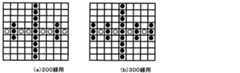
(グレーパターンマッチング323f)
図25に示すように、本実施例ではDをグレー画素として、bkはクレー画素より濃いところとして、下記パターンマッチングを行う。複写原稿は、薄い200線の万線パターン、300線の万線であるので、複写原稿もクレー検出するように下記のようなパターンを採用している。下記パターンに一致したものは、グレー画素となる(図26(a)、(b)参照)。(Gray pattern matching 323f)
As shown in FIG. 25, in this embodiment, the following pattern matching is performed on the assumption that D is a gray pixel and bk is darker than the clay pixel. Since the copy original has a thin line pattern of 200 lines and a line of 300 lines, the following pattern is adopted so that the copy original also detects clay. A pixel that matches the following pattern is a gray pixel (see FIGS. 26A and 26B).
4.)白パターン補正
白画素パターンマッチングで孤立(1×1、1×2、2×1、2×2、1×3、3×1の白画素)しているアクティブ画素を非アクティブにする。このことにより、孤立している画素を除去する。
5.)白膨張
白画素パターンマッチングの補正の結果を7×41のORを行う。
6.)白収縮
白膨張の結果の1×33のANDを行う。白膨張と白収縮を行うことにより、白画素パターンマッチングの補正結果に対して膨張と小面積で存在する非アクティブ画素を除去する。この判定結果は、白地と境界部分に対して、非白地側の境界領域を含む結果となる。言いかえれば、白地よりも大きな領域となる。4). ) White Pattern Correction Active pixels that are isolated (white pixels of 1 × 1, 1 × 2, 2 × 1, 2 × 2, 1 × 3, 3 × 1) by white pixel pattern matching are deactivated. This removes isolated pixels.
5. ) White Expansion The result of white pixel pattern matching correction is ORed 7 × 41.
6). )
7.)白補正
白ブロック補正では、ブロックパターンBCPの×を付した注目画素を中心とした15×11画素において、四隅の各6×4画素領域それぞれに1つ以上の白候補ブロックが存在するときに、注目ブロックに白ブロック補正データを与える。このことにより、白地に囲まれた領域を白領域とする。7). ) White correction In white block correction, when there are one or more white candidate blocks in each of the 6 × 4 pixel regions at the four corners in the 15 × 11 pixel centered on the pixel of interest marked with “X” in the block pattern BCP. The white block correction data is given to the target block. As a result, a region surrounded by a white background is set as a white region.
8.)グレー膨張
図25に示すように、本実施例ではグレーパターンマッチングの結果に対して、11×11のOR処理をする。このことにより、グレー領域に対してやや大きな領域となる。8). ) Gray Expansion As shown in FIG. 25, in this embodiment, 11 × 11 OR processing is performed on the result of gray pattern matching. This makes the area slightly larger than the gray area.
9.)判定
白補正の結果がアクティブまたは、収縮結果がアクティブでかつグレー膨張結果が非アクティブの時に白背景とする。式で表現すると次式のようになる。
白補正の結果 # (白収縮の結果 & !グレー膨張の結果)
ここで、白補正の結果では、白地にかっ込まれた領域を確実に白領域と判定して、白収縮の結果 & !グレー膨張の結果の結果では、濃い黒文字周辺を白領域として、濃度の薄いところを非白領域としている。9. ) Determination When the white correction result is active, or when the shrinkage result is active and the gray expansion result is inactive, the white background is used. It can be expressed as the following equation.
White correction result # (white shrinkage result &! Gray expansion result)
Here, in the result of white correction, the area enclosed in the white background is definitely determined as the white area, and the result of white contraction &! As a result of the gray expansion, a dark black character periphery is set as a white area, and a low density area is set as a non-white area.
図13に、丸Bp1〜Bp4で囲んだ黒の突出部は、上述の、注目ブロックを中心とした15×11画素において四隅の各6×4画素領域それぞれに1つ以上の白候補ブロックが存在するときに注目ブロックに白ブロック補正データを与える白ブロック補正、によって白ブロックに置きかえられる。丸Bp1〜Bp4で囲んだ黒の突出部のように白地で囲まれた黒領域を、白領域とすることは、そこを絵柄部と判定する可能性を低減する。後述する総合判定326では、非白領域は絵柄と判定するが、丸Bp1〜Bp4で囲んだ黒の突出部のように白地で囲まれた黒領域を絵柄と誤判定する可能性が減る。 In FIG. 13, the black protrusions surrounded by the circles Bp1 to Bp4 have one or more white candidate blocks in each of the 6 × 4 pixel areas at the four corners in the 15 × 11 pixels centering on the block of interest described above. The white block is replaced by white block correction that gives white block correction data to the target block. Making a black area surrounded by a white background like the black protrusions surrounded by the circles Bp1 to Bp4 as a white area reduces the possibility of determining that it is a picture part. In the
さらに、白収縮の結果、グレー膨張の結果にて、黒地と白地境界を白領域(文字領域)と判定するので、濃い文字エッジは、文字の太さにかかわらず白地判定するので、文字エッジを正しく文字エッジと判定することが可能となる。濃度の薄い部分は文字エッヂ判定しなくなる。 Furthermore, as a result of white shrinkage, the boundary between the black background and the white background is determined as a white area (character area) based on the result of gray expansion, so a dark character edge is determined as a white background regardless of the thickness of the character. It becomes possible to correctly determine a character edge. A character edge is not judged in a portion with a low density.
(文字/写真判定レベルの調整)
上述のように白領域抽出323では、白判定323cで、RGB白抽出323bの白地判定信号,色地判定信号dおよび谷白画素判定信号、ならびに、2値化323aの2値化白判定信号、に対応する、白の程度をあらわす状態変数である白地情報MSを生成する。そして白パターンマッチング323dで、該色地判定信号d,白地情報MS,2値化白判定信号および谷白画素判定信号に基づいて注目画素が白画素か否を仮に定めて、注目画素を含む画素マトリスクに対する白画素分布パターンマッチングによって白画素か否を確定する。この結果と、黒判定323eおよび黒パターンマッチング323fの結果を用いて、白補正323gが、注目画素が黒地と白地境界との境界(白領域:文字領域)であるかを判定する。(Adjustment of text / photo judgment level)
As described above, in the
RGB白抽出323bの白地判定信号(図5のステップ3で参照)は、注目画素のR,G,B画像データのすべてが閾値thwss=40より小さいと「1」(白地)である。この閾値thwssを大きくすると大きい値の白地情報MSを定める確率が高くなり、上記「白領域」(黒地と白地境界との境界:文字領域)を摘出する確率が高くなる(すなわち絵柄領域を摘出する確率が低下する)。閾値thwssを小さくするとこの逆となる。 The white background determination signal (see
2値化323aの2値化白判定信号(図5のステップ7で参照)は、フィルタ321のG画像データのエッジ強調出力が閾値thwsb=50より小さければ、「1」(2値化白)である。この閾値thwsbを大きくすると大きい値の白地情報MSを定める確率が高くなり、上記「白領域」を摘出する確率が高くなる(すなわち絵柄領域を摘出する確率が低下する)。閾値thwsbを小さくするとこの逆となる。 The binarized white determination signal of the binarization 323a (refer to step 7 in FIG. 5) is “1” (binarized white) if the edge enhancement output of the G image data of the
「白領域」の画像データには後工程で、文字画像を鮮明に表すための画像処理が施されるので、閾値thwssおよびthwsbを大きくすると、文字に優先度が高い画像処理が施される。非白領域すなわち絵柄(写真)領域の画像データには後工程で、写真や絵柄を忠実に表すための画像処理が施されるので、閾値thwssおよびthwsbを小さくすると、絵柄(写真)に優先度が高い画像処理が施される。 Since the image data for “white area” is subjected to image processing for clearly expressing the character image in a later step, when the threshold values thwss and thwsb are increased, image processing with high priority is performed on the characters. The image data in the non-white area, that is, the picture (picture) area, is subjected to image processing for faithfully representing the picture or picture in a later process. Therefore, if the threshold values thwss and thwsb are reduced, the priority is given to the picture (picture). High image processing is performed.
ところで、RGB白抽出323bの色地判定信号d(図5のステップ6で参照)が「1」(色地)であると白地情報MSを低くし、上記「白領域」を摘出する確率が低くなる(すなわち絵柄領域を摘出する確率が高くなる)。前記2.)色地検出で色地判定信号dを生成する処理B.,C.で用いる閾値thwc(例えば20)を小さくすると、周辺画素(図11の△と□)を同時に色画素と検出する確率すなわち(bとcのエクスクルーシブノア)=「1」となる確率がたかくなって色地判定信号d=「1」(色地)を得る確率が高くなり、上記「白領域」を摘出する確率が低くなる(すなわち絵柄領域を摘出する確率が高くなる)。 By the way, when the color background determination signal d (refer to step 6 in FIG. 5) of the RGB white extraction 323b is “1” (color background), the white background information MS is lowered, and the probability of extracting the “white area” is low. (That is, the probability of extracting the pattern area increases). 2. B) Processing for generating a color gamut determination signal d by color gamut detection. , C.I. When the threshold thwc (for example, 20) used in the above is reduced, the probability of simultaneously detecting neighboring pixels (Δ and □ in FIG. 11) as color pixels, that is, the probability of (exclusive NOR of b and c) = “1” increases. The probability of obtaining the color background determination signal d = “1” (color background) increases, and the probability of extracting the “white area” decreases (that is, the probability of extracting the pattern area increases).
そこで本実施例では、図2の操作/表示部OPBにて、キー入力による入力モードのメニュー表示ならびに液晶ディスプレに表示されたメニュー画面上のキー画像(パラメータ指定キーおよびアップ,ダウンキー)の操作によって調整するパラメータ調整の中の「文字/写真レベル」の調整によって、閾値thwss,thwsbおよびthwcを次のように調整するようにしている。 Therefore, in the present embodiment, in the operation / display unit OPB of FIG. 2, the menu display of the input mode by key input and the operation of the key image (parameter designation key and up / down key) on the menu screen displayed on the liquid crystal display. The threshold values thwss, thwsb, and thwc are adjusted as follows by adjusting the “character / photo level” in the parameter adjustment to be adjusted by the following.
すなわち、オペレータが操作/表示部OPBにて調整設定するパラメータ「文字/写真レベル」の標準値(デフォルト)は「3」であり、このデフォルト値が、上記の文字/写真レベルと閾値thwss,thwsbおよびthwcとの関係をあらわす変換テーブルと共に、図3に示すROM358に書き込まれており、図3に示すIPU300に電源が投入されCPU357がIPU300の初期化をするときに、CPU357がROM358から文字/写真レベルのデフォルト値を読み出して、それに対応する閾値thwss,thwsbおよびthwcを変換テーブルから読み出してRAM356の、各閾値宛てレジスタに書きこんで、白領域抽出323での上述の処理に用いる。その後操作ボードOPBからの入力で文字/写真レベルの調整があり、調整後の値Aがメインコントローラ10からCPU357に与えられると、CPU357は、調整後の値Aに対応するパラメータthwss,thwsbおよびthwcの各値を、ROM358の変換テーブルから読み出して、RAM356の、パラメータ宛てレジスタに書きこむ。 That is, the standard value (default) of the parameter “character / photo level” that is adjusted and set by the operator on the operation / display unit OPB is “3”, and the default value is the above-described character / photo level and threshold values thwss, thwsb. 3 is written in the ROM 358 shown in FIG. 3 together with a conversion table representing the relationship between the CPU 357 and the thwc. When the power is turned on to the
閾値を標準値thwss=40,thwsb=50,thwc=20に設定しているときに、操作ボードOPBを使ってオペレータが「文字/写真レベル」の値をi(例えば1)だけ大きく「Up」すると、閾値thwss,thwsbおよびthwcが2i(2)分、文字優先方向に変更した値に定められる。逆に、オペレータが「文字/写真レベル」の値をi(例えば1)だけ小さく「Down」すると、閾値thwss,thwsbおよびthwcが2i(2)分、写真優先方向に変更した値に定められる。 When the threshold values are set to the standard values thwss = 40, thwsb = 50, and thwc = 20, the operator uses the operation board OPB to increase the value of “character / photo level” by i (for example, 1) to “Up”. Then, the threshold values thwss, thwsb, and thwc are set to values that are changed in the character priority direction by 2i (2). Conversely, when the operator decreases the value of “character / photo level” by “Down” by i (for example, 1), the thresholds thwss, thwsb, and thwc are set to values that are changed in the photo priority direction by 2i (2).
(網点抽出324)
第1網点ピーク検出324aは、G画像データを用いて、所定の大きさの二次元局所領域内の画素濃度情報から、網点ドットの一部を形成する画素(網点ピーク画素と呼ぶ)を検出する回路である。局所領域に関して、次の二つの条件が同時に成立するときに、領域の中心画素を網点ピーク画素として検出する。
条件1:中心画素の濃度レベルが局所領域内で最大(山ピーク)または最小(谷ピーク)である;
条件2:中心画素に対し点対称関係にある全ての画素のペアについて、画素ペアの濃度レベルの平均と中心画素の濃度レベルとの差の絶対値が、閾値Th以上であること。(Halftone dot extraction 324)
The first halftone dot peak detection 324a uses G image data, and forms pixels of halftone dots (referred to as halftone peak pixels) from pixel density information in a two-dimensional local region having a predetermined size. Is a circuit for detecting When the following two conditions are satisfied simultaneously for the local region, the central pixel of the region is detected as a halftone dot peak pixel.
Condition 1: The density level of the central pixel is maximum (mountain peak) or minimum (valley peak) in the local region;
Condition 2: The absolute value of the difference between the average density level of the pixel pair and the density level of the central pixel is greater than or equal to the threshold Th for all pixel pairs that are in point symmetry with respect to the central pixel.
図14を参照して、第1網点ピーク検出324aの検出処理を具体的に説明する。局所領域として5×5画素マトリクス(一般化して示すとM×M画素マトリクス)のマスクを採用した例である。5×5画素マトリクスの各画素の符号を、図11のパターンMPpに示すものとすると、注目画素となる中心画素c3の濃度Lcが、その周囲画素の濃度L1〜L8と比較して最大または最小であるとともに、
abs(2Lc−L1−L8)≧Lth
かつabs(2Lc−L2−L7)≧Lth
かつabs(2Lc−L3−L6)≧Lth
かつabs(2Lc−L4−L5)≧Lth
のときに、マスクの中心画素(Lc)を網点ピーク画素として検出する。abs関数は絶対値をとることを意味する。Lthは閾値(固定値)である。With reference to FIG. 14, the detection process of the 1st halftone peak detection 324a is demonstrated concretely. In this example, a 5 × 5 pixel matrix (M × M pixel matrix when generalized) mask is used as the local region. If the sign of each pixel of the 5 × 5 pixel matrix is as shown in the pattern MPp of FIG. 11, the density Lc of the center pixel c3 serving as the target pixel is the maximum or minimum compared to the densities L1 to L8 of the surrounding pixels. And
abs (2Lc-L1-L8) ≧ Lth
And abs (2Lc-L2-L7) ≧ Lth
And abs (2Lc-L3-L6) ≧ Lth
And abs (2Lc-L4-L5) ≧ Lth
At this time, the center pixel (Lc) of the mask is detected as a halftone dot peak pixel. The abs function means taking an absolute value. Lth is a threshold value (fixed value).
具体的には、周囲画素は、図14に示す周囲画素分布パターンMPaまたはMPbの、4角形を付記した画素とする。周囲画素分布パターンMPaとMPbに基づいた上述の網点ピーク画素検出のどちらかが、網点ピーク画素と検出した時に、そのときの注目画素(中心画素c3)に網点ピーク画素を表す検出信号を与える。2つのパターンを用いるのは、網点の線数に幅広く対応するためである。 Specifically, the surrounding pixels are pixels to which a quadrangle of the surrounding pixel distribution pattern MPa or MPb shown in FIG. 14 is added. When either halftone dot peak pixel detection based on the surrounding pixel distribution patterns MPa and MPb detects a halftone peak pixel, a detection signal that represents a halftone dot pixel at the current pixel of interest (center pixel c3) give. The reason for using the two patterns is to deal with a wide range of halftone dot lines.
パターンMPaは、L1=b2,L2=b3,L3=b4,L4=c2,L5=c4,L6=d2,L7=d3,L8=d4、と定めたものである。ここで、L1=b2とは、画素b2の濃度を、上述の網点ピーク画素検出演算のL1の値とすることを意味する。 The pattern MPa is defined as L1 = b2, L2 = b3, L3 = b4, L4 = c2, L5 = c4, L6 = d2, L7 = d3, L8 = d4. Here, L1 = b2 means that the density of the pixel b2 is set to the value of L1 in the above-described halftone peak pixel detection calculation.
パターンMPbは、L1=b2,L2=a3,L3=b4,L4=c1,L5=c5,L6=d2,L7=e3,L8=d4、と定めたものである。 The pattern MPb is defined as L1 = b2, L2 = a3, L3 = b4, L4 = c1, L5 = c5, L6 = d2, L7 = e3, L8 = d4.
また、複写の場合、副走査方向yの拡大,縮小はスキャナ200の原稿走査速度の低,高で行うので、スキャナ200からは、副走査方向yの拡大,縮小があった画像データが与えられる。そこで、縮小のときには、上述のパターンMPa,MPbにかえて、図14上に示すパターンMPc,MPdを用いる。拡大のときには、図14上に示すパターンMPe,MPfを用いる。なお、パターンMPe,MPfにおいて、三角印を与えた画素も、上述の「周囲画素」に加えても良い。 In the case of copying, enlargement / reduction in the sub-scanning direction y is performed at low and high document scanning speeds of the
第2網点ピーク検出324bは、Bデータを用いて網点ピーク検出するものであって、機能は、第1網点ピーク検出324aと同じである。第1網点ピーク検出324aは、G画像データを用いるのでほとんどの色に対して反応するが、Yに対しては反応しないので第2網点ピーク検出324cでは、B画像データを使用して、Yの網点ピークを検出することを目的としている補助的なものである。 The second halftone peak detection 324b detects halftone dots using the B data, and has the same function as the first halftone peak detection 324a. Since the first halftone peak detection 324a uses G image data and reacts to most colors, but does not react to Y, the second halftone peak detection 324c uses B image data, It is a supplementary object aimed at detecting the Y dot peak.
網点領域検出324cは、第1網点ピーク画素検出324a,第2網点ピーク画素検出324bのどちらかにより検出された山と谷の網点ピーク画素を、所定の大きさの二次元の小領域毎に計数し、山と谷の網点ピーク画素の合計を小領域の計数値Pとする。この計数値Pが閾値Pthより大きいときに、小領域の全画素(あるいは画素単位の処理の場合、小領域の中心画素のみ)を網点領域と判定する。判定の結果は一時メモリ324dに記憶される。 The halftone dot region detection 324c is a two-dimensional small-sized pixel having a predetermined size, which is a peak and valley halftone dot pixel detected by either the first halftone dot peak pixel detection 324a or the second halftone dot peak pixel detection 324b. It counts for every area | region, and makes the sum total of the halftone dot peak pixel of a peak and a valley the count value P of a small area | region. When the count value P is larger than the threshold value Pth, all the pixels in the small area (or in the case of pixel unit processing, only the central pixel of the small area) are determined as halftone dot areas. The result of the determination is stored in the temporary memory 324d.
図23aを参照して、第3網点ピーク検出の検出処理を具体的に説明する。なお、第3網点ピーク検出処理の流れは、図22に示すとおりである。この第3網点ピーク検出処理は、100線以下、65線(新聞の網点)以上を検出することを目的としている。 With reference to FIG. 23a, the detection process of the 3rd halftone peak detection is demonstrated concretely. The flow of the third halftone peak detection process is as shown in FIG. The third halftone dot peak detection process is intended to detect 100 lines or less and 65 lines (newspaper halftone dots) or more.
局所領域として7×7画素マトリクス(一般化して示すとM×M画素マトリクス)のマスクを採用した例である。図23cのパターンに示すものとすると、注目画素となる中心画素群の濃度Lcが、その周囲画素の濃度群L1〜L8と比較して最大または最小であるとともに、
abs(2Lc−L1−L8)≧Lth
かつabs(2Lc−L2−L7)≧Lth
かつabs(2Lc−L3−L6)≧Lth
かつabs(2Lc−L4−L5)≧Lth
のときに、マスクの中心画素(Lc)を網点ピーク画素として検出する。abs関数は絶対値をとることを意味する。Lthは閾値(固定値)である。This is an example in which a mask of a 7 × 7 pixel matrix (M × M pixel matrix when generalized) is adopted as the local region. As shown in the pattern of FIG. 23c, the density Lc of the central pixel group as the target pixel is maximum or minimum as compared with the density groups L1 to L8 of the surrounding pixels, and
abs (2Lc-L1-L8) ≧ Lth
And abs (2Lc-L2-L7) ≧ Lth
And abs (2Lc-L3-L6) ≧ Lth
And abs (2Lc-L4-L5) ≧ Lth
At this time, the center pixel (Lc) of the mask is detected as a halftone dot peak pixel. The abs function means taking an absolute value. Lth is a threshold value (fixed value).
ここで、マスクの中心画素(Lc)が最大値の時の網点ピーク画素を網点山ピーク画素として、周期チェック1に出力する。また、マスクの中心画素(Lc)が最小値の時の網点ピーク画素を網点谷ピーク画素として、周期チェック2に出力する。 Here, the halftone dot peak pixel when the center pixel (Lc) of the mask is the maximum value is output to the
具体的には、周囲画素は、図23aに示す周囲画素分布パターンした画素とする。周囲画素分布パターンに基づいた上述の網点ピーク画素検出のどちらかが、網点ピーク画素と検出した時に、そのときの注目画素(中心画素d4)に網点ピーク画素を表す検出信号を与える。2つのパターンを用いるのは、網点の網点面積率に幅広く対応するためである。 Specifically, the surrounding pixels are pixels having the surrounding pixel distribution pattern shown in FIG. When one of the above-described halftone dot pixel detection based on the surrounding pixel distribution pattern detects a halftone dot pixel, a detection signal representing the halftone dot pixel is given to the target pixel (center pixel d4) at that time. The reason why the two patterns are used is to deal with a wide range of halftone dot area ratios.
Lcの濃度は周辺画素を参照して以下のように求める。
Lc=Min(d4,d3、d5、c4、e4)
このLcが周辺画素に対して最大値の時は、
パターンは、L1=Max(a1、a2、b1)
L2=Max(a3、a4、a5)
L3=Max(a6、a7、c7)
L4=Max(c1、d1、e1)
L5=Max(c7、d7、e7)
L6=Max(f1、g1、g2)
L7=Max(g3、g4、g5)
L8=Max(g6、g7、f7)
と定めたものである。ここで、L1=Max(a1、a2、b1)とは、画素a1、a2、b1の濃度の最大値を、上述の網点ピーク画素検出演算のL1の値とすることを意味する。Lc=Min(d4,d3、d5、c4、e4)とは、d4,d3、d5、c4、e4の濃度(画像データ)の最小値を意味する。The density of Lc is obtained as follows with reference to surrounding pixels.
Lc = Min (d4, d3, d5, c4, e4)
When this Lc is the maximum value for the surrounding pixels,
The pattern is L1 = Max (a1, a2, b1)
L2 = Max (a3, a4, a5)
L3 = Max (a6, a7, c7)
L4 = Max (c1, d1, e1)
L5 = Max (c7, d7, e7)
L6 = Max (f1, g1, g2)
L7 = Max (g3, g4, g5)
L8 = Max (g6, g7, f7)
It is determined. Here, L1 = Max (a1, a2, b1) means that the maximum density value of the pixels a1, a2, and b1 is set as the L1 value in the above-described halftone peak pixel detection calculation. Lc = Min (d4, d3, d5, c4, e4) means the minimum value (image data) of d4, d3, d5, c4, e4.
また、Lc=Max(d4,d3、d5、c4、e4)
このLcが周辺画素に対して最小値の時は、
パターンは、L1=Min(a1、a2、b1)
L2=Min(a3、a4、a5)
L3=Max(a6、a7、c7)
L4=Max(c1、d1、e1)
L5=Max(c7、d7、e7)
L6=Max(f1、g1、g2)
L7=Max(g3、g4、g5)
L8=Max(g6、g7、f7)
と定めたものである。Lc = Max (d4, d3, d5, c4, e4)
When this Lc is the minimum value for the surrounding pixels,
The pattern is L1 = Min (a1, a2, b1)
L2 = Min (a3, a4, a5)
L3 = Max (a6, a7, c7)
L4 = Max (c1, d1, e1)
L5 = Max (c7, d7, e7)
L6 = Max (f1, g1, g2)
L7 = Max (g3, g4, g5)
L8 = Max (g6, g7, f7)
It is determined.
また、複写の場合、副走査方向yの拡大,縮小はスキャナ200の原稿走査速度の低,高で行うので、スキャナ200からは、副走査方向yの拡大,縮小があった画像データが与えられる。そこで、縮小のときには、図23bに示すパターンを用いる。拡大のときには、図23aに示すパターンを用いる。 In the case of copying, enlargement / reduction in the sub-scanning direction y is performed at low and high document scanning speeds of the
網点ピーク検出3の演算式は、1画素のデータで演算するのではなく、複数の画素(min、maxの演算)で、対象となる画素を参照する。これは、低線数の網点は濃淡の周期が大きくなので、1画素で決定するのでは周辺画素を参照することにより、ノイズ(ごみ)の影響を少なし、かつ、算術演算量を減らし、他のブロックを共通に演算式を使えるようにしているので、ハード化が容易である。 The calculation formula for halftone
周期チェック1では、網点山ピークと網点山ピークの周期をチェックする。主走査1次元方向に網点山ピークの間隔をチェックする。網点ピーク検出の検出対象の網点は、検出線数100線以下なので、網点山ピークは、白黒網点時は、8以上となる。8未満の場合は小さな文字を誤判定して場合がほとんどある(600dpi読み取り時)。 In
しかし、網点部は白黒印刷の場合、スクリーン角が45であるが、カラー印刷は色毎にスクリーン角が異なる。スクリーン角と主走査の周期の関係は以下の様になる。 However, the halftone dot portion has a screen angle of 45 in monochrome printing, but the color printing has a different screen angle for each color. The relationship between the screen angle and the main scanning cycle is as follows.
ここで、100線以下の網点とその以外を判別するには、100以下は、周期8以上と6になる。ここで、周期7を含めていないのは、120線の白黒網点が周期7近傍(7.07)であるからある。さらに、周期6の網点を100線以下としないのは、マゼンタ、シアン、イエロー網点が周期6近傍(7.3、7.06)であるからである。つまり、周期2、3、4、5、7の時は、100以下の網点で無いので、網点山ピークを除去する。 Here, to discriminate halftone dots of 100 lines or less and others, 100 or less becomes
スクリーン角を考慮して周期チェックを行うことにより、文字の誤判定なしに100線以下のカラー網点を良好に検出することが出来る。 By performing a periodic check in consideration of the screen angle, color halftone dots of 100 lines or less can be detected well without erroneous character determination.
図24aに示すように、L1が5で、L2が10であれば、L1間隔の網点山ピークは、小さな文字である場合がほとんどなので、網点山ピークを除去する。L2間隔は、低線数網点である場合がほとんどなので、除去はしない。 As shown in FIG. 24a, when L1 is 5 and L2 is 10, the halftone peak between the L1 intervals is almost always a small character, so the halftone peak is removed. Since the L2 interval is mostly a low line number halftone dot, it is not removed.
周期チェックで、図24aが、図24bのように補正される。周期チェック2では、網点谷ピークを、周期チェック1と同様に行う。網点山ピークと網点谷ピークを独立に行うのは、網点面積率50%近傍においては、網点山ピークと網点谷ピークが交互に現れ正確な周期が、現れないために独立に行っている。周期チェック1、周期チェック2の出力をorして、網点領域検出部2に入力する。 In the period check, FIG. 24a is corrected as shown in FIG. 24b. In
網点領域検出2は周期チェック1、2をorして、山と谷の網点ピーク画素を、所定の大きさの二次元の小領域毎に計数し、山と谷の網点ピーク画素の合計を小領域の計数値Pとする。この計数値Pが閾値Pthより大きいときに、小領域の全画素(あるいは画素単位の処理の場合、小領域の中心画素のみ)を網点領域と判定する。判定の結果は一時メモリに記憶される。 The halftone
さらに、網点領域検出3は周期チェック1、2をorして、山と谷の網点ピーク画素を、所定の大きさの二次元の小領域毎に計数し、山と谷の網点ピーク画素の合計を小領域の計数値Pとする。この計数値Pが閾値Pthより大きいときに、小領域の全画素(あるいは画素単位の処理の場合、小領域の中心画素のみ)を網点領域と判定する。判定の結果は一時メモリBに記憶される。 Further, the halftone
領域検出部1または、領域検出部2のどちらかが、網点領域ならば、注目している小領域の近傍の処理済み領域の網点/非網点判定結果(周辺の特徴情報)に応じ適応的に閾値Pthを変化させる。本実施例においては、閾値Pthとして、二つの値TH1,TH2(ただしTH1>TH2)が用意され、一時メモリ324dに記憶されている注目小領域近傍の処理済み領域の判定結果によって、その一方の値を選択する。すなわち、近傍の領域が非網点領域と判定されていた場合には、線画領域である可能性が高いので、誤検出を減らすために条件が厳しくなるTH1のほうを閾値Pthとして選択する。これに対し、近傍領域が網点領域であると判定されていた場合には、網点領域である可能性が高いので、条件が緩くなるTH2のほうを閾値Pthとして用いる。なお、閾値Pthの初期値としてはTH1を選択する。 If either of the
図14上のAMPに、上述の小領域の分布を示す。小領域分布パターンAMPのS1〜S4のそれぞれは、例えば4×4画素の大きさの小領域(ブロック)であり、S4が注目している小領域、S1,S2およびS3は処理済みの小領域であるとする。S1,S2およびS3のすべてが網点領域であると判定されている時には、Th2がS4の判定のための閾値Pthとして用いられる。S1,S2およびS3の一つでも非網点領域と判定されているときは、閾値PthとしてTH1が選択される。網点領域と判定したときに“1”で、非網点と判定した時に“0”の網点領域検出信号htが網点抽出324から出力される。ただし、これは一例であって、S1,S2およびS3のいずれか一つの小領域でも網点領域と判定されたときにTH2を選択し、すべてが非網点領域と判定されたときにのみTH1を選択するようにしてもよい。さらに、参照する近傍領域をS1のみ、あるいはS2のみとすることもできる。この出力結果は、網点抽出結果である。 AMP on FIG. 14 shows the distribution of the above-mentioned small regions. Each of S1 to S4 of the small area distribution pattern AMP is, for example, a small area (block) having a size of 4 × 4 pixels. S4 is a small area of interest, and S1, S2, and S3 are processed small areas. Suppose that When it is determined that all of S1, S2, and S3 are halftone areas, Th2 is used as the threshold value Pth for the determination of S4. If any one of S1, S2 and S3 is determined to be a non-halftone area, TH1 is selected as the threshold value Pth. A halftone dot region detection signal ht is output from the
領域検出部2、網点領域ならば、注目している小領域の近傍の処理済み領域の網点/非網点判定結果(周辺の特徴情報)に応じ適応的に閾値Pthを変化させる。本実施例においては、閾値Pthとして、二つの値TH1,TH2(ただしTH1>TH2)が用意され、一時メモリBに記憶されている注目小領域近傍の処理済み領域の判定結果によって、その一方の値を選択する。すなわち、近傍の領域が非網点領域と判定されていた場合には、線画領域である可能性が高いので、誤検出を減らすために条件が厳しくなるTH1のほうを閾値Pthとして選択する。これに対し、近傍領域が網点領域であると判定されていた場合には、網点領域である可能性が高いので、条件が緩くなるTH2のほうを閾値Pthとして用いる。なお、閾値Pthの初期値としてはTH1を選択する。 If the
図14上のAMPに、上述の小領域の分布を示す。小領域分布パターンAMPのS1〜S4のそれぞれは、例えば4×4画素の大きさの小領域(ブロック)であり、S4が注目している小領域、S1,S2およびS3は処理済みの小領域であるとする。S1,S2およびS3のすべてが網点領域であると判定されている時には、Th2がS4の判定のための閾値Pthとして用いられる。S1,S2およびS3の一つでも非網点領域と判定されているときは、閾値PthとしてTH1が選択される。網点領域と判定したときに“1”で、非網点と判定した時に“0”の網点領域検出信号htが網点抽出324から出力される。ただし、これは一例であって、S1,S2およびS3のいずれか一つの小領域でも網点領域と判定されたときにTH2を選択し、すべてが非網点領域と判定されたときにのみTH1を選択するようにしてもよい。さらに、参照する近傍領域をS1のみ、あるいはS2のみとすることもできる。この出力結果は、低線網点抽出結果である。
網点抽出結果との処理の違いは、網点ピーク検出では、低線数の入力のみで網点抽出をしているので、低線数網点のみの抽出が可能となっている。AMP on FIG. 14 shows the distribution of the above-mentioned small regions. Each of S1 to S4 of the small area distribution pattern AMP is, for example, a small area (block) having a size of 4 × 4 pixels. S4 is a small area of interest, and S1, S2, and S3 are processed small areas. Suppose that When it is determined that all of S1, S2, and S3 are halftone areas, Th2 is used as the threshold value Pth for the determination of S4. If any one of S1, S2 and S3 is determined to be a non-halftone area, TH1 is selected as the threshold value Pth. A halftone dot region detection signal ht is output from the
The difference in processing from the halftone dot extraction result is that, in halftone dot detection, halftone dots are extracted only with a low line number input, so that only low line number halftone dots can be extracted.
(色判定325)
原稿中の色(有彩)画素や黒(無彩)画素を検出する際には、R,G,Bの相対的な読み取りずれが、各色画像データのサンプリングや機械的精度のために存在する。図15を用いて説明する。図15の(a)は、画像濃度信号で、黒濃度信号は理想的には、R,B,G濃度信号ともレベルの高低が一致したとき理想の黒である。ところが、実際の画像データは、レンズでCCD上に画像を結像し、CCDの画像信号をデジタル化したもので、図15の(b)が理想の高低波形となる。しかし、一般的なスキャナでは、3ラインCCDセンサを用いているため、画像データのR,G,Bの各画像を時間的に同時に読み取るのではなく、R,G,Bの各ラインセンサは等間隔で配置され、時間的に同時に読むことができないので、どうしても読み取り位置ずれが生じてしまう。例えば、図15の(b)に示すレベル変化の黒を表すR,G,B各色濃度信号は、図15の(c)に示すように、相対的にずれる。このずれが大きいと、黒領域の周縁に色ずれが現れる。(Color determination 325)
When detecting color (chromatic) pixels and black (achromatic) pixels in a document, there is a relative reading shift of R, G, and B due to sampling of each color image data and mechanical accuracy. . This will be described with reference to FIG. FIG. 15A shows an image density signal. The black density signal is ideally black when the levels of the R, B, and G density signals coincide with each other. However, the actual image data is obtained by forming an image on a CCD with a lens and digitizing the image signal of the CCD. FIG. 15B shows an ideal high and low waveform. However, since a general scanner uses a three-line CCD sensor, the R, G, B line sensors are not read simultaneously in time, but the R, G, B line sensors are equal. Since they are arranged at intervals and cannot be read simultaneously in time, the reading position will inevitably shift. For example, the R, G, and B color density signals representing the level-change black shown in FIG. 15B are relatively shifted as shown in FIG. If this shift is large, a color shift appears at the periphery of the black area.
(色相分割325a)
色判定325は、有彩色領域を見つけるものである。入力データR,G,Bは、色相分割325aにて、c,m,yおよび色判定用w(白)の信号に変換される。色相分割の例としては、それぞれの色の境界を求め、1画素内のR,G,Bそれぞれの画像データの最大値と最小値の差をRGB差と定義して、以下のようにした。ここでは、R,G,B画像データは、数字が大きくなると黒くなる(濃くなる)。
1).R−Y色相領域境界(ry)
R - 2 * G + B > 0
2).Y−G色相領域境界(yg)
11 * R - 8 * G - 3 * B > 0
3).G−C色相領域境界(gc)
1 * R - 5 * G + 4 * B < 0
4).C−B色相領域境界(cb)
8 * R - 14 * G + 6 * B < 0
5).B−M色相領域境界(bm)
9 * R - 2 * G - 7 * B < 0
6).M−R色相領域境界(mr)
R + 5 * G - 6 * B < 0。(Hue Division 325a)
The
1). RY hue region boundary (ry)
R-2 * G + B> 0
2). YG hue region boundary (yg)
11 * R-8 * G-3 * B> 0
3). GC hue region boundary (gc)
1 * R-5 * G + 4 * B <0
4). CB hue region boundary (cb)
8 * R-14 * G + 6 * B <0
5). BM hue region boundary (bm)
9 * R-2 * G-7 * B <0
6). MR hue region boundary (mr)
R + 5 * G-6 * B <0.
7).色判定用w(白)画素判定:
(R < thwa) & (G < thwa) & (B < thwa)ならば、y=m=c=0とする。thwaは閾値である。7). Color determination w (white) pixel determination:
If (R <thwa) & (G <thwa) & (B <thwa), y = m = c = 0. thwa is a threshold value.
8).Y画素判定:
(ry == 1) & (yg == 0) & (RGB差 > thy)ならば、y=1、m=c=0とする。thyは閾値である。8). Y pixel determination:
If (ry == 1) & (yg == 0) & (RGB difference> thy), then y = 1 and m = c = 0. thy is a threshold value.
9).G画素判定:
(yg == 1) & (gc == 0) & (RGB差 > thg)ならば、c=y=1、m=0とする。thgは閾値である。9). G pixel determination:
If (yg == 1) & (gc == 0) & (RGB difference> thg), c = y = 1 and m = 0. thg is a threshold value.
10).C画素判定:
(gc == 1) & (cb == 0) & (RGB差 > thc)ならば、c=1、m=y=0とする。thcは閾値である。10). C pixel determination:
If (gc == 1) & (cb == 0) & (RGB difference> thc), c = 1 and m = y = 0. thc is a threshold value.
11).B画素判定:
(cb == 1) & (bm == 0) & (RGB差 > thb)ならば、m=c=1、y=0とする。thbは閾値である。11). B pixel determination:
If (cb == 1) & (bm == 0) & (RGB difference> thb), m = c = 1 and y = 0. thb is a threshold value.
12).M画素判定:
(bm == 1) & (mr == 0) & (RGB差 > thm)ならば、m=1、y=c=0とする。thmは閾値である。12). M pixel determination:
If (bm == 1) & (mr == 0) & (RGB difference> thm), then m = 1 and y = c = 0. thm is a threshold value.
13).R画素判定:
(mr == 1) & (ry == 0) & (RGB差 > thr)ならば、y=m=1、c=0とする。thrは閾値である。13). R pixel determination:
If (mr == 1) & (ry == 0) & (RGB difference> thr), y = m = 1 and c = 0. thr is a threshold value.
14).BK画素判定:7).〜13).に該当しない時、y=m=c=1とする。 14). BK pixel determination: 7). To 13). If not, y = m = c = 1.
さらに、色判定用w画素の判定を行う。条件は以下のようになる:
(R < thw) & (G < thw) & (B < thw)ならば、色画素用w画素とし、wとして出力する。thwは閾値である。ここで、7)〜14)の優先順位は、数の小さい方を優先する。上述の閾値thwa,thy,thm,thc,thr,thg,thbは、複写(処理)前に決まる閾値である。thwとthwaの関係は、thw>thaとなっている。出力信号は、c,m,yに各1ビットの3ビットデータと、さらに、色判定用色画素検出のwの1ビットである。ここで色相毎に閾値をかえているのは、色相領域毎に、有彩範囲が異なる時に色相領域に応じた閾値を決定する。この色相分割は、一例であって、どんな式を使用してもよい。Further, the color determination w pixel is determined. The conditions are as follows:
If (R <thw) & (G <thw) & (B <thw), the color pixel is set as a w pixel and is output as w. thw is a threshold value. Here, the priority of 7) to 14) is given priority to the smaller number. The above-mentioned thresholds thwa, thy, thm, thc, thr, thg, thb are thresholds determined before copying (processing). The relationship between thw and thwa is thw> tha. The output signal is 3 bits of data of 1 bit for each of c, m, and y, and 1 bit of w for color pixel detection for color determination. Here, the threshold is changed for each hue because the threshold corresponding to the hue area is determined for each hue area when the chromatic range is different. This hue division is an example, and any formula may be used.
色相分割325aの出力c,m,y,wは、ラインメモリ325b〜325eに5ライン蓄え、色画素判定325fに入力する。 The outputs c, m, y, and w of the hue division 325a are stored in five lines in the
(色画素判定325f)
図6に、色画素判定325fの内容を示す。5ライン分の、c,m,y,wのデータは、パターンマッチング325f5〜325f7と、カウント325f1〜325fに入力する。ここでまず、B/C信号を求める流れの中のパターンマッチング325f6について説明する。(
FIG. 6 shows the contents of the
(パターンマッチング325f6)
色画素用w画素が存在する時は、その画素のc=m=y=0に補正する。この補正により、注目画素を中心とする5×5画素マトリクスの白レベルが大きくなる。次に注目画素が、色相分割325aで判定した画素のc,m,yの全てが1(c=m=y=1)または全てが0(c=m=y=0)以外の画素(色画素)であるかを、該5×5画素マトリクスがつぎのパターンにマッチングするかをチェックすることによって判定する:
1).色画素パターン群
1―1).パターン1―1(pm1)
D23 & D33 & D43
1―2).パターン1―2(pm2)
D32 & D33 & D34
1―3).パターン1―3(pm3)
D22 & D33 & D44
1―4).パターン1―4(pm4)
D24 & D33 & D42
中心画素(注目画素)は、D33である。図16にこれらのパターンpm1〜pm4を示す。これらのパターン上の白丸は、c,m,yの少なくとも一者が1であることを示す。パターンマッチングを採用するのは、孤立点などを拾わないようにするためである。逆に、網点などの、小面積色検出する際には、中心画素が1(c=m=y=1)または全てが0(c=m=y=0)以外の画素(色画素)であるかで、判定すればよい。(Pattern matching 325f6)
When the color pixel w pixel exists, the pixel is corrected to c = m = y = 0. This correction increases the white level of the 5 × 5 pixel matrix centered on the pixel of interest. Next, the pixel of interest is a pixel (color) other than 1 (c = m = y = 1) or all 0 (c = m = y = 0) of the pixels determined by the hue division 325a. Is determined by checking whether the 5 × 5 pixel matrix matches the following pattern:
1). Color pixel pattern group 1-1). Pattern 1-1 (pm1)
D23 & D33 & D43
1-2). Pattern 1-2 (pm2)
D32 & D33 & D34
1-3). Pattern 1-3 (pm3)
D22 & D33 & D44
1-4). Pattern 1-4 (pm4)
D24 & D33 & D42
The center pixel (target pixel) is D33. FIG. 16 shows these patterns pm1 to pm4. White circles on these patterns indicate that at least one of c, m, and y is 1. Pattern matching is used to prevent picking up isolated points. On the other hand, when detecting a small area color such as a halftone dot, the central pixel is a pixel (color pixel) other than 1 (c = m = y = 1) or all 0 (c = m = y = 0). It may be determined whether or not.
2).色細線用パターン群
白に囲まれた色線を検出する。これに用いるパターンを図17に示す。図17において、白丸を付した画素は、c,m,yが全て0の画素である。注目画素(中心画素)を中心とする5×5画素マトリクスのデータ(c,m,y)の分布が、図17のパターンpw11a〜pw14dのいずれかにマッチングすると、そのときの注目画素(中心画素)を色線画素と見なす:
2―1).パターン2―1(pw11a〜pw11d)
((D12&D13&D14)&(D42&D43&D44))#
((D12&D13&D14)&(D52&D53&D54))#
((D22&D23&D42)&(D42&D43&D44))#
((D22&D23&D42)&(D52&D53&D54))
2―2).パターン2―2(pw12a〜pw12d)
((D21&D31&D41)&(D24&D34&D44))#
((D21&D31&D41)&(D25&D35&D45))#
((D22&D23&D24)&(D24&D34&D44))#
((D22&D23&D24)&(D25&D35&D45))
2―3).パターン2―3(pw13a〜pw13d)
((D11&D21&D12)&(D35&D44&D53))#
((D11&D21&D12)&(D45&D44&D55))#
((D13&D22&D31)&(D35&D44&D53))#
((D13&D22&D31)&(D45&D44&D55))
2―4).パターン2―4(pw14a〜pw14d)
((D13&D24&D35)&(D41&D51&D52))#
((D14&D15&D25)&(D41&D51&D52))#
((D13&D24&D35)&(D31&D42&D53))#
((D14&D15&D25)&(D31&D42&D53))。2). Color line pattern group Detects a color line surrounded by white. The pattern used for this is shown in FIG. In FIG. 17, pixels with white circles are pixels in which c, m, and y are all 0. When the distribution of the data (c, m, y) of the 5 × 5 pixel matrix centered on the target pixel (center pixel) matches any of the patterns pw11a to pw14d in FIG. 17, the target pixel (center pixel) at that time ) Is considered a color line pixel:
2-1). Pattern 2-1 (pw11a-pw11d)
((D12 & D13 & D14) & (D42 & D43 & D44)) #
((D12 & D13 & D14) & (D52 & D53 & D54)) #
((D22 & D23 & D42) & (D42 & D43 & D44)) #
((D22 & D23 & D42) & (D52 & D53 & D54))
2-2). Pattern 2-2 (pw12a-pw12d)
((D21 & D31 & D41) & (D24 & D34 & D44)) #
((D21 & D31 & D41) & (D25 & D35 & D45)) #
((D22 & D23 & D24) & (D24 & D34 & D44)) #
((D22 & D23 & D24) & (D25 & D35 & D45))
2-3). Pattern 2-3 (pw13a-pw13d)
((D11 & D21 & D12) & (D35 & D44 & D53)) #
((D11 & D21 & D12) & (D45 & D44 & D55)) #
((D13 & D22 & D31) & (D35 & D44 & D53)) #
((D13 & D22 & D31) & (D45 & D44 & D55))
2-4). Pattern 2-4 (pw14a-pw14d)
((D13 & D24 & D35) & (D41 & D51 & D52)) #
((D14 & D15 & D25) & (D41 & D51 & D52)) #
((D13 & D24 & D35) & (D31 & D42 & D53)) #
((D14 & D15 & D25) & (D31 & D42 & D53)).
3).白領域パターン群
c,m,yが全て0のところのパターンマッチングを行う。これに用いるパターンを図18に示す。図18において、白丸を付した画素は、c,m,yが全て0の画素である。注目画素(中心画素)を中心とする5×5画素マトリクスのデータ(c,m,y)の分布が、図18のパターンpw21a〜pw24dのいずれかにマッチングすると、そのときの注目画素(中心画素)を白領域画素と見なす:
3―1).パターン3―1(pw21a〜pw21d)
(D21&D31&D41)#
(D22&D32&D42)#
(D24&D34&D44)#
(D25&D35&D45)
3―2).パターン3―2(pw22a〜pw22d)
(D12&D13&D14)#
(D22&D23&D24)#
(D42&D43&D44)#
(D52&D53&D54)
3―3).パターン3―3(pw23a〜pw23d)
(D52&D51&D41)#
(D53&D42&D31)#
(D35&D24&D13)#
(D25&D15&D14)
3―4).パターン3―4(pw24a〜pw24d)
(D54&D55&D45)#
(D53&D44&D35)#
(D31&D22&D13)#
(D21&D11&D12)。3). White area pattern group Pattern matching is performed where c, m, and y are all zero. The pattern used for this is shown in FIG. In FIG. 18, pixels with white circles are pixels in which c, m, and y are all 0. When the distribution of the data (c, m, y) of the 5 × 5 pixel matrix centered on the target pixel (center pixel) matches any of the patterns pw21a to pw24d in FIG. 18, the target pixel (center pixel) at that time ) As white area pixels:
3-1). Pattern 3-1 (pw21a-pw21d)
(D21 & D31 & D41) #
(D22 & D32 & D42) #
(D24 & D34 & D44) #
(D25 & D35 & D45)
3-2). Pattern 3-2 (pw22a to pw22d)
(D12 & D13 & D14) #
(D22 & D23 & D24) #
(D42 & D43 & D44) #
(D52 & D53 & D54)
3-3). Pattern 3-3 (pw23a-pw23d)
(D52 & D51 & D41) #
(D53 & D42 & D31) #
(D35 & D24 & D13) #
(D25 & D15 & D14)
3-4). Pattern 3-4 (pw24a-pw24d)
(D54 & D55 & D45) #
(D53 & D44 & D35) #
(D31 & D22 & D13) #
(D21 & D11 & D12).
4).色画素候補2の判定
上記で抽出したパターンマッチング結果が以下のパターンに一致すれば、注目画素を、色判定用色画素候補2とする:
((pm1 == 1) & ((pw11 == 1) # (pw21 != 1))) #
((pm2 == 1) & ((pw12 == 1) # (pw22 != 1))) #
((pm3 == 1) & ((pw13 == 1) # (pw23 != 1))) #
((pm4 == 1) & ((pw14 == 1) # (pw24 != 1)))
ここで、(pm1 == 1)は、注目画素を中心とするデータ分布が、パターンpm1にマッチングすることを意味し、(pw11 == 1)はパターンpw11a〜pw11dのいずれかにマッチングすることを意味し、(pw21 != 1)はパターンpw21a〜pw21dのいずれかにマッチングすることを意味する。&は論理積を、#は論理和を意味する。このパターンマッチングにより、白領域に囲まれた色画素を色画素候補として、それ以外で白領域が存在する時は、色画素としない。白領域がない色画素パターンマッチングで一致したものは、色画素候補となる。4). Determination of
((pm1 == 1) & ((pw11 == 1) # (pw21! = 1))) #
((pm2 == 1) & ((pw12 == 1) # (pw22! = 1))) #
((pm3 == 1) & ((pw13 == 1) # (pw23! = 1))) #
((pm4 == 1) & ((pw14 == 1) # (pw24! = 1))))
Here, (pm1 == 1) means that the data distribution centered on the pixel of interest matches the pattern pm1, and (pw11 == 1) means that it matches any of the patterns pw11a to pw11d. This means that (pw21! = 1) matches with any of the patterns pw21a to pw21d. & Means logical product, and # means logical sum. With this pattern matching, a color pixel surrounded by a white area is set as a color pixel candidate, and when there is a white area other than that, it is not set as a color pixel. Those matched by color pixel pattern matching without a white area are color pixel candidates.
(カウント325f1)
注目画素を中心とする5×5画素マトリクス内に、色判定用w画素が存在する時は、その画素の色相分割325aで判定したc,m,yデータをc=m=y=0に補正する。この補正により、該画素マトリクスの白レベルが大きくなる。そして、該画素マトリクス内の各画素のc,m,yの1(c=1,m=1,y=1)の数をカウントする。c,m,yそれぞれについてのカウント値の最大値と最小値との差が、thcnt以上でかつ最小値がthmin未満ならば、色画素候補1とする。thcnt,thminは、複写(処理)前に設定する閾値である。y,m,cにプレーン展開して、N×Nのマトリクスにおいてのそれぞれのプレーン毎に数を数えて、最小値をブラックと仮定している。このことにより、黒画素の読み取りが漏れても補正が可能となる。そして最大値と最小値の差で有彩画素を判定している。このことにより、黒画素が読み取りから外れた画素を補正して、有彩画素を抽出する。注目画素を中心とする5×5画素マトリクス内に一定画素の有彩画素があると注目画素を有彩画素としている。(Count 325f1)
When there are w pixels for color determination in the 5 × 5 pixel matrix centered on the target pixel, the c, m, y data determined by the hue division 325a of the pixel is corrected to c = m = y = 0. To do. This correction increases the white level of the pixel matrix. Then, the number of c, m, and y 1 (c = 1, m = 1, y = 1) of each pixel in the pixel matrix is counted. If the difference between the maximum value and the minimum value of the count values for c, m, and y is greater than or equal to thcnt and the minimum value is less than thmin,
(色画素判定325f8)
パターンマッチング325f6とカウント325f1の出力にもとづいて、色画素判定325f8で、色画素か否かを判定する。色画素候補1でかつ色画素候補2であれば、色画素1とする。(Color pixel determination 325f8)
Based on the outputs of the pattern matching 325f6 and the count 325f1, a color pixel determination 325f8 determines whether the pixel is a color pixel. If the
(ブロック化325f9)
色画素判定325f8の出力をブロック化325f9にてブロック化をする。ブロック化とは、4×4画素のマトリックスにおいて、1画素以上の色画素1があれば、該4×4画素マトリックス全体を色画素1ブロックとして、出力する。ブロック化325f9以降の処理は、4×4画素を1ブロックとしてブロック単位出力する。(Blocked 325f9)
The output of the color pixel determination 325f8 is blocked at block 325f9. Blocking means that if there is one or
(孤立点除去325f10)
ブロック化したデータを孤立点除去325f10にて、注目ブロックの隣り合うブロックに色画素1ブロックがなければ孤立点として、除去する。(Isolated point removal 325f10)
Blocked data is removed as an isolated point in isolated point removal 325f10 if there is no color pixel block in the adjacent block of the target block.
(膨張325f11)
孤立点除去325f10の出力を、膨張325f11にて、色画素1ブロックが存在する場合は、5×5ブロックに膨張する。膨張するのは、色画素の周辺を、黒文字処理をしないようにするためである。ここで、出力するB/C信号は、色画素1ブロックの時にL(有彩)を出力し、それ以外の時は、H(無彩)を出力する。(Expansion 325f11)
In the expansion 325f11, the output of the isolated point removal 325f10 is expanded to 5 × 5 blocks when there is one color pixel block. The reason for expansion is to prevent black character processing around the color pixel. Here, the output B / C signal outputs L (chromatic) when the color pixel is one block, and outputs H (achromatic) at other times.
(カウント325f2)
注目画素を中心とする5×5画素マトリクス内に色判定用w画素が存在する時は、その画素の色相分割325aで判定したc,m,yデータをc=m=y=0に補正する。この補正により、該画素マトリクスの白レベルが大きくなる。そして、該画素マトリクス内の各画素の、c,m,yの1(c=1,m=1,y=1)の数をカウントする。c,m,yそれぞれについてのカウント値の最大値と最小値との差が、thacnt以上でかつ最小値がthamin未満ならば、注目画素を色画素候補1とする。thacnt,thaminは、複写(処理)前に設定する閾値である。(Count 325f2)
When the w determination pixel exists in the 5 × 5 pixel matrix centered on the target pixel, the c, m, and y data determined in the hue division 325a of the pixel are corrected to c = m = y = 0. . This correction increases the white level of the pixel matrix. Then, the number of c, m, and y of 1 (c = 1, m = 1, y = 1) of each pixel in the pixel matrix is counted. If the difference between the maximum value and the minimum value of the count values for c, m, and y is greater than or equal to thacnt and less than the minimum value, the pixel of interest is set as a
(色画素判定325f12)
パターンマッチング325f6とカウント325f2の出力にもとづいて、色画素判定325f12で、色画素か否かを判定する。色画素候補1でかつ色画素候補2であれば、色画素2とする。(Color pixel determination 325f12)
Based on the outputs of the pattern matching 325f6 and the count 325f2, the color pixel determination 325f12 determines whether or not the pixel is a color pixel. If it is the
(ブロック化325f13)
色画素判定325f12の出力をブロック化325f13にてブロック化をする。即ち、4×4画素のマトリックスにおいて、1画素以上の色画素2があれば、該4×4画素マトリックの全体を色画素2ブロックとして、出力する。ブロック化325f13以降の処理は、4×4画素を1ブロックとしてブロック単位出力する。(Blocked 325f13)
The output of the color pixel determination 325f12 is blocked by a block 325f13. That is, if there is one or
(密度325f14)
孤立ブロックの除去のために、3×3ブロックの中のアクティブ条件(色画素2ブロック)が3個以上あり、注目ブロックがアクティブ(色画素)ならば、注目ブロックをアクティブブロック(色画素2ブロック)とする。(Density 325f14)
In order to remove an isolated block, if there are three or more active conditions (
(カウント325f3)
注目画素を中心とする5×5画素マトリクス内の各画素の、c,m,yの1(c=1,m=1,y=1)の数をカウントする。c,m,yそれぞれについてのカウント値の最大値と最小値との差が、tha1cnt以上で、かつカウントしたc,m,yの最小値が、tha1min未満ならば、色画素候補3とする。tha1cnt,tha1minは、複写(処理)前に設定する閾値である。(Count 325f3)
The number of c, m, y of 1 (c = 1, m = 1, y = 1) of each pixel in the 5 × 5 pixel matrix centered on the target pixel is counted. If the difference between the maximum value and the minimum value of c, m, and y for each of c, m, and y is equal to or greater than tha1cnt, and the counted minimum value of c, m, and y is less than tha1min,
(パターンマッチング325f5)
色画素検出で判定した画素(c、m、y)が色画素かを、5×5画素マトリクスを用いるパターンマッチングで判定する。パターンはパターンマッチング325f6のものと同じである。パターンマッチングで一致した画素は、色画素候補4とする。(Pattern matching 325f5)
Whether the pixel (c, m, y) determined by color pixel detection is a color pixel is determined by pattern matching using a 5 × 5 pixel matrix. The pattern is the same as that of pattern matching 325f6. The pixel matched by pattern matching is set as a
(色画素判定325f15)
色画素候補3でかつ色画素候補4であれば、色画素3とする。(Color pixel determination 325f15)
If it is the
(ブロック化325f16)
色画素判定325f15の出力をブロック化325f16にてブロック化をする。すなわち、4×4画素のマトリックスにおいて、1画素以上の色画素3があれば、該4×4画素マトリックスの全体を色画素3ブロックとして、出力する。ブロック化325f16以降の処理は、4×4を1ブロックとしてブロック単位出力する。(Blocked 325f16)
The output of the color pixel determination 325f15 is blocked at a block 325f16. That is, if there is one or
(密度325f17)
孤立ブロックの除去のために、3×3ブロックの中のアクティブ条件(色画素3ブロック)が3個以上あり、注目ブロックがアクティブ(色画素3)ならば、注目ブロックをアクティブブロック(色画素3ブロック)とする。(Density 325f17)
If there are three or more active conditions (
(カウント325f4)
注目画素を中心とする5×5画素マトリクス内の各画素の、色相分割325aで判定したc,m,yの1(c=1,m=1,y=1)の数をカウントする。c,m,yの各カウント値の最小値が、thabk以上ならば、注目画素を黒画素候補1とする。thabkは、複写(処理)前に設定する閾値である。(Count 325f4)
The number of 1 of c, m, and y (c = 1, m = 1, y = 1) determined by the hue division 325a of each pixel in the 5 × 5 pixel matrix centered on the target pixel is counted. If the minimum value of each count value of c, m, and y is greater than or equal to thabk, the pixel of interest is set as a
(パターンマッチング325f7)
注目画素を中心とする5×5画素マトリクスにおいて、c=m=y=1の画素のパターンマッチングを行う。(Pattern matching 325f7)
In a 5 × 5 pixel matrix centered on the pixel of interest, pattern matching is performed on pixels with c = m = y = 1.
1―1).パターン1―1(pm1)
D23&D33&D43
1―2).パターン1―2(pm2)
D32&D33&d34
1―3).パターン1―3(pm3)
D22&D33&D44
1―4).パターン1―4(pm4)
D42&D33& D24
これらのパターンは図16に示すものであり、図中に丸印を付した画素が、c=m=y=1の画素である。これらのパターンのどれかに一致した時に、注目画素を黒画素候補2とする。1-1). Pattern 1-1 (pm1)
D23 & D33 & D43
1-2). Pattern 1-2 (pm2)
D32 & D33 & d34
1-3). Pattern 1-3 (pm3)
D22 & D33 & D44
1-4). Pattern 1-4 (pm4)
D42 & D33 & D24
These patterns are shown in FIG. 16, and the pixels with circles in the figure are pixels with c = m = y = 1. When matching with any of these patterns, the target pixel is set as a
(無彩判定325f18)
注目画素が、黒画素候補1でかつ黒画素候補2であれば、黒画素とする。(Achromatic determination 325f18)
If the pixel of interest is
(ブロック化325f19)
黒画素の出力をブロック化325f19にてブロック化をする。ここでのブロック化とは、4×4画素のマトリックスにおいて、1画素以上の黒画素があれば、該4×4画素マトリックスの全体を黒画素ブロックとして、出力する。ブロック化325f19以降の処理は、4×4画素を1ブロックとしてブロック単位出力する。(Blocked 325f19)
Black pixel output is blocked at block 325f19. In this block formation, if there is one or more black pixels in a 4 × 4 pixel matrix, the entire 4 × 4 pixel matrix is output as a black pixel block. In the processing after blocking 325f19, 4 × 4 pixels are regarded as one block and output is made in block units.
(膨張325f20)
3×3ブロックのマトリックス内において、注目ブロックがアクティブ(黒画素ブロック)で、その周辺画素がノンアクティブ(非黒画素)ならば、注目ブロックをノンアクティブ(非黒画素ブロック)にする。(Expansion 325f20)
If the target block is active (black pixel block) and its surrounding pixels are non-active (non-black pixel) in the 3 × 3 block matrix, the target block is made non-active (non-black pixel block).
(総合色画素判定325f21)
注目ブロックが、色画素判定325f12でアクティブ(色画素2)と判定されかつ無彩判定325f18でアクティブ(黒画素)と判定されていなければ、注目ブロックは色(色ブロック)と判定する。また、色画素判定325f15がアクティブ(色画素)の時も色と判定する。(Total color pixel determination 325f21)
If the target block is determined to be active (color pixel 2) in the color pixel determination 325f12 and not determined to be active (black pixel) in the achromatic determination 325f18, the target block is determined to be a color (color block). The color is also determined when the color pixel determination 325f15 is active (color pixel).
(膨張325f22)
総合色画素判定325f21で、色と判定したブロックに対して小さな文字を連続と見なすために、注目ブロックを中心とする9×9ブロックのマトリックス内に1ブロックでもアクティブブロックがあれば、注目ブロックをアクティブブロックとする。ここで、大きく膨張させるのは、文字同士のすき間を埋めるためである。(Expansion 325f22)
In order to regard small characters as continuous for the block determined to be a color in the overall color pixel determination 325f21, if there is even one active block in the 9 × 9 block matrix centered on the target block, the target block is determined. The active block. Here, the reason for the large expansion is to fill the gap between the characters.
(連続カウント325f23)
連続カウント325f23では、色画素ブロックの連続性を見て、カラー原稿か白黒原稿かを判定する。膨張325f22の出力データ(色画素ブロック)の中の色画素の連続数をカウントすることにより、カラー原稿かどうか判定する。(Continuous count 325f23)
In the continuous count 325f23, it is determined whether the original is a color original or a monochrome original by looking at the continuity of the color pixel blocks. By counting the number of continuous color pixels in the output data (color pixel block) of the expansion 325f22, it is determined whether the document is a color document.
図7に、この判定処理の内容を示す。注目画素が色画素ブロックにある時に注目画素の左上,上,右上および左の画素の色画素連続数を参照して、注目画素の色画素連続数を算出する(ステップ21〜26)。ここで、注目画素を、例えば図11の5×5画素分布パターンMPpのc3画素とすると、左上,上,右上および左の画素はそれぞれ、b2,b3,b4およびc2の画素である。注目画素が色画素ブロックにないときには、それには0なる色画素連続数を与える(ステップ21−27)。 FIG. 7 shows the contents of this determination process. When the target pixel is in the color pixel block, the number of continuous color pixels of the target pixel is calculated with reference to the number of continuous color pixels of the upper left, upper, upper right and left pixels of the target pixel (
注目画素が色画素ブロックにある場合は、先ず注目画素(c3)の上画素(b3)の色画素連続数をチェックして(ステップ22)、それが0であると、参照値Aに右上画素(b4)の色画素連続数に1を加えた値を与え(ステップ24)、上画素(b3)の色画素連続数が0であると参照値Aに右上画素(b4)の色画素連続数を与える(ステップ23)。次に、参照値Bに左上画素(b2)の色画素連続数に1を加えた値を与え、参照値Cには上画素(b3)の色画素連続数に1を加えた値を与え、また参照値Dには左画素(c2)の色画素連続数に1を加えた値を与える(ステップ25)。そして、参照値A,B,CおよびDのうちの最高値を、注目画素(c3)の色画素連続数とする(ステップ26)。 When the target pixel is in the color pixel block, first, the number of continuous color pixels of the upper pixel (b3) of the target pixel (c3) is checked (step 22). A value obtained by adding 1 to the number of continuous color pixels of (b4) is given (step 24), and the number of continuous color pixels of the upper right pixel (b4) is added to the reference value A when the number of continuous color pixels of the upper pixel (b3) is 0. (Step 23). Next, a value obtained by adding 1 to the number of continuous color pixels of the upper left pixel (b2) is given to the reference value B, and a value obtained by adding 1 to the number of continuous color pixels of the upper pixel (b3) is given to the reference value B. Further, a value obtained by adding 1 to the number of continuous color pixels of the left pixel (c2) is given to the reference value D (step 25). Then, the highest value among the reference values A, B, C and D is set as the number of continuous color pixels of the target pixel (c3) (step 26).
注目画素(c3)に色画素連続数を上述のように与えると、この色画素連続数が設定値THACS以上であるかをチェックして(ステップ28)、THACS以上であると、カラー原稿であると決定して(ステップ29)、そこで連続カウント325f23の処理を終える。色画素連続数が設定値THACS未満であると、注目画素を走査方向x,yの次の画素に更新して、上述の処理を繰返す。原稿全面について上述の処理をした結果、最後まで色画素連続数が設定値THACS未満であったときには(ステップ30〜34)、原稿は白黒画像であると決定する。 When the number of continuous color pixels is given to the target pixel (c3) as described above, it is checked whether the number of continuous color pixels is equal to or larger than the set value THACS (step 28). Is determined (step 29), and the processing of the continuous count 325f23 is ended there. If the number of continuous color pixels is less than the set value THACS, the target pixel is updated to the next pixel in the scanning directions x and y, and the above-described processing is repeated. As a result of performing the above-described processing on the entire surface of the original, if the number of continuous color pixels is less than the set value THACS until the end (steps 30 to 34), it is determined that the original is a monochrome image.
上述の色画素連続数は、ほぼたての色付き線分と横の色付き線分の和となる。右上の色画素連続数が、他と異なるのは二重カウントを防ぐためである。色画素連続数の具体的なデータを、図19に示した。図19に示す数字を入れた小四角が色画素であり、数字が該画素に与えた色画素連続数である。数字を入れた小四角が連なったブロックが色画素群であり、同一原稿上のどれかの色画素群のなかの色画素連続数が1つでも設定値THACS以上になるとそこで、カラー原稿である、とカラーか白黒かの判定を確定する(ステップ28,29)。 The above-mentioned number of consecutive color pixels is the sum of almost a fresh colored line segment and a horizontal colored line segment. The number of consecutive color pixels in the upper right is different from others because it prevents double counting. Specific data on the number of continuous color pixels is shown in FIG. A small square including a number shown in FIG. 19 is a color pixel, and the number is a continuous number of color pixels given to the pixel. A block consisting of a series of small squares with numbers is a color pixel group, and even if one continuous color pixel in any color pixel group on the same document exceeds the set value THACS, it is a color document. , The determination of color or black and white is confirmed (
色画素判定1〜3(325f8−325f15)と分けたのは、カラー原稿か白黒原稿かの判定精度を高くするためである。黒文字処理のための色画素判定は、誤判定をしても局所的でさほど目立たない。しかし、カラー原稿か白黒原稿かの判定は、誤判定をすると原稿全体に影響する。そこで、カウント325f1−f4を独立とした。本来ならば、色相分割325aから独立にした方がよいが色相分割325aを独立にすると、パターンマッチング325f5−f7のメモリが増えるので、好ましくない。カウント325f1−f4のパラメータ(色画素候補1,3,黒画素候補1)で、色画素のパラメータ(色画素1−3)を変更している事により、メモリ量の増加を少なくしている。色画素判定2,3(325f12,325f15)を設けているのは蛍光ペンの黄色のような濃度の低い色を検出するためで、さらに、無彩判定(黒画素判定)325f18を備えたのは濃度を低くすると誤検出した際に補正するためである。蛍光ペンなど濃度の薄い色は、ある程度の幅で黒データで補正しても問題はない。複数の色画素を抽出する際に、w(白)のレベルを変えているだけなので、色画素検出のために2つ分のメモリを持つ必要がなく、1つ分+1ラインの容量で可能である。 The reason why it is divided from the
連続カウント325f23で、1ライン前のカウントデータと現在のラインのカウントデータを参照してカウント値を数えているので、確実に周辺画素の連続を正確に数えることができるので色画素の連続を数えることが可能となる。本実施例は、R,G,B画像データに対して色相判定を行ったが、R,G,B画像データに限定するものではなく、輝度色差(例えばLab)などに対して、色相判定することは、容易である。 In the continuous count 325f23, the count value is counted by referring to the count data of the previous line and the count data of the current line. Therefore, it is possible to accurately count the continuity of the peripheral pixels, and thus count the continuity of the color pixels. It becomes possible. In this embodiment, the hue determination is performed on the R, G, B image data. However, the hue determination is not limited to the R, G, B image data, and the hue determination is performed on the luminance color difference (for example, Lab). It is easy.
(総合判定326)
総合判定326は、文字判定326a,膨張処理326b,文字なか判定326cおよびデコード326dからなる。なお、上述のエッジ抽出結果、白領域抽出結果、網点抽出結果、低線数網点抽出結果、色判定結果についての総合判定は図27に示す通りである。(Overall judgment 326)
The
(文字判定326a)
文字判定326aでは、エッジ抽出322の結果がエッジありで、網点抽出324の結果が網点なしで白領域抽出323の結果が白領域ありのときは、文字エッジと判定する。そうでないときには非文字エッジ(絵柄又は文字なか)と判定する。(Character determination 326a)
In the character determination 326a, if the result of the
(膨張処理326b)
膨張処理326bでは、文字判定326bの結果を8×8ブロックのOR処理をして、その後に3×3ブロックのAND処理をして4ブロックの膨張処理を行う。すなわち、注目ブロックを中心とする8×8ブロックのいずれかのブロックが文字エッジであると、注目ブロックも文字エッジブロックであると仮定し、該注目ブロックを中心とする3×3ブロックのすべてが文字エッジであると注目ブロックを文字エッジと確定し、そして、注目ブロックとそれに隣接する3ブロック、計4ブロックを文字エッジと見なす。OR処理してからAND処理するのは、特に黒文字の場合、黒文字の領域の周辺に小領域の非黒文字領域が存在すると、処理の差により違和が感じられることがある。例えば黒が薄く見える。これを防ぐために、OR処理で非黒文字領域を大きくしている。AND処理は、望むべき膨張量にするために行っている。(Expansion treatment 326b)
In the expansion process 326b, the result of the character determination 326b is subjected to OR processing of 8 × 8 blocks, and then AND processing of 3 × 3 blocks is performed to perform expansion processing of 4 blocks. That is, if any block of the 8 × 8 block centered on the target block is a character edge, it is assumed that the target block is also a character edge block, and all 3 × 3 blocks centered on the target block are If it is a character edge, the target block is determined as the character edge, and the target block and three blocks adjacent to the target block are regarded as the character edge. The reason why the AND process is performed after the OR process, particularly in the case of a black character, when a small non-black character area exists around the area of the black character, a difference may be felt due to a difference in processing. For example, black looks thin. In order to prevent this, the non-black character area is enlarged by OR processing. The AND process is performed to obtain a desired expansion amount.
ところでカラー複写機は、1枚の複写をするのに、4回スキャンをするので、スキャン毎に、微妙に文字判定結果が異なる。特に、ブラック作像時に非黒文字判定をし、ブラック作像以外のときに黒文字判定をすると、この黒文字領域は薄くなってしまうので、bk時には8×8ブロックのOR処理をして、その後に3×3ブロックのAND処理をしてbk以外の作像時は、5×5ブロックのOR処理をして、その後は1×1ブロックのAND処理をする。なお、1×1のAND処理をする、と言うことは、その結果が処理前と同一になるので、何の処理もしないと言うことと同義である。膨張処理の結果は、文字エッジ信号としてデコード326dに出力する。 By the way, since a color copying machine scans four times to make one copy, the character determination result slightly differs for each scan. In particular, if non-black character determination is performed at the time of black image formation and black character determination is performed at times other than black image formation, this black character region becomes thin. Therefore, at bk, 8 × 8 block OR processing is performed, and then 3 When the AND processing of the × 3 block is performed and other than bk is formed, the OR processing of the 5 × 5 block is performed, and thereafter the AND processing of the 1 × 1 block is performed. Note that performing 1 × 1 AND processing is synonymous with performing no processing because the result is the same as before processing. The result of the expansion process is output to the decode 326d as a character edge signal.
このように膨張処理をすることにより、分離結果が異なって文字の領域が薄くなることがなくなる。この膨張処理によって、文字の中部分が濃くなることがあるが、文字のエッジに対して文字のなかは薄いのと濃度は飽和しているので、違和感はない。 By performing the expansion process in this way, the separation result is different and the character area is not thinned. This expansion process may darken the middle part of the character, but there is no sense of incongruity because the character is lighter than the character edge and the density is saturated.
図20に、カラー複写によるカラー色剤の重なりを、模式的に拡大して示す。図20の(d)が、4色とも黒文字処理した理想の場合を示す。図20の(e)が、4色とも黒文字処理して、bkのみ補正がかからず、bk以外で補正がかかって薄くなった場合を示す。図20の(f)が、本実施例によってbkのみ黒文字処理した、好適な場合を示し、図20の(g)が、本実施例によってbkのみ黒文字処理して、bkのみ補正がかからず、bk以外で補正がかかった好適な場合を示す。 FIG. 20 schematically shows an enlargement of the overlapping of the color colorants by color copying. FIG. 20D shows an ideal case where black characters are processed for all four colors. (E) of FIG. 20 shows a case where black characters are processed for all four colors, and only bk is not corrected, and correction other than bk is applied and lightened. FIG. 20 (f) shows a preferable case where only black characters are processed according to this embodiment, and FIG. 20 (g) shows that black characters are processed only for black characters according to this embodiment, and only bk is not corrected. , Bk is a preferable case where correction is applied.
図20の(a)が、膨張量は同一で黒文字処理した理想の場合を示す。図20の(b)は、膨張量は同一で黒文字処理して印字位置がずれた場合(白く抜ける)を示す。図20の(c)が、bkの膨張量が大きい場合で、本実施例によって黒文字処理して印字位置がずれた場合を示す。 FIG. 20A shows an ideal case where the expansion amount is the same and black characters are processed. FIG. 20B shows the case where the expansion amount is the same and the print position is shifted after black character processing (out of white). FIG. 20C shows a case where the printing position is shifted by black character processing according to the present embodiment when the expansion amount of bk is large.
(デコード326d)
デコード326dが最終的に出力するC/P信号は、以下の表のようになる。(Decode 326d)
The C / P signal finally output by the decode 326d is as shown in the following table.
次に、再度図3を参照する。原稿認識320が発生するC/P信号およびB/C信号は、RGBフィルタ330,色補正340,変倍350,インターフェイス352,UCR360,CMYBkフィルタ370,CMYBkγ補正380および階調処理390に、画像データに同期してカスケードに与えられる。 Next, FIG. 3 will be referred to again. The C / P signal and the B / C signal generated by the document recognition 320 are supplied to the RGB filter 330, the color correction 340, the magnification change 350, the
RGBフィルタ330は、RGBデータをMTF補正するフィルタであり、N×Nの画素マトリックスに対応する係数マトリクスと、各係数に各画像データを乗じて重み付け平均値を得るロジックで構成されている。C/P信号が1を表すもの(文字エッジ領域)である時には、鮮鋭化処理用の係数マトリクスを用い、0又は2、3を表すもの(絵柄領域、低線数網点領域、網点領域)である時には平滑化処理用の係数マトリクスを用いて、重み付け平均値を導出し色補正340に出力する。ここでの平滑化フィルタは、平滑化量の強い順に並べると、低線数網点領域、網点領域、絵柄領域となる。これは、網点は平滑を強くしないと網点構造が残り、モアレの原因となるためのである、さらに低線数の網点は、高線数の網点より強く平滑化してやる必要がある。色補正340は、R,G,Bデータを一次のマスキング処理等でC,M,Yデータに変換する。変倍350は、画像データに、主走査方向xの拡大・縮小または等倍処理を施す。 The RGB filter 330 is a filter that performs MTF correction on RGB data, and includes a coefficient matrix corresponding to an N × N pixel matrix and logic that multiplies each coefficient by each image data to obtain a weighted average value. When the C / P signal is 1 (character edge area), the coefficient matrix for sharpening processing is used to represent 0, 2, or 3 (picture area, low linearity dot area, dot area) ), A weighted average value is derived using a coefficient matrix for smoothing processing and output to the color correction 340. If the smoothing filters here are arranged in descending order of the smoothing amount, they become a low linear number halftone dot region, a halftone dot region, and a pattern region. This is because a halftone dot structure will remain if halftone dots are not strengthened and cause moire. Further, halftone dots with a low line number need to be smoothed more strongly than halftone dots with a high line number. The color correction 340 converts R, G, B data into C, M, Y data by a primary masking process or the like. A scaling unit 350 performs enlargement / reduction in the main scanning direction x or equal magnification processing on the image data.
UCR360は、画像データの色再現を向上させるためのものであり、色補正340から入力したC,M,Yデータの共通部分をUCR(加色除去)処理してBkデータを生成し、C,M,Y,Bkデータを出力する。ここで、C/P信号が1(文字エッジ領域)以外の時(文字なか領域又は絵柄領域のとき)は、スケルトンブラック処理を行う。C/P信号が3(文字エッジ領域)の時は、フルブラック処理を行う。さらにC/P信号が1(文字エッジ領域)かつB/C信号がH(無彩領域)の時は、C,M,Yのデータをイレースする。これは、黒文字の時、黒成分のみで表現するためである。 The
また、UCR360の出力画像信号IMGは、一時点はC,M,Y,Bkのうち一色であり、面順次の一色出力である。すなわち、4回原稿読み取りを行うことにより、フルカラー(4色)データを生成する。また、白黒複写のときは、Bk作像一回でよいので、1回の原稿読み取りでよい。カラー原稿か、白黒原稿かの判定機構があれば、原稿に応じた読み取り回数ですむので、操作者が、原稿に応じてカラー原稿か白黒原稿かを判断して複写する必要がなくなる。本実施例では、B/C信号がカラー原稿か、白黒原稿かの判定に参照する信号である。原稿全面でB/C信号がH(無彩領域)であったときにメインコントローラ10が、白黒原稿と判定する。 Further, the output image signal IMG of the
CMYBkフィルタ370は、カラープリンタ400の周波数特性やC/P信号に応じて、N×Nの空間フィルタを用い、平滑化や鮮鋭化処理を行う。CMYBkγ補正380は、カラープリンタ400の周波数特性やC/P信号に応じて、γカーブを変更し処理する。C/P信号が1(文字エッジ領域以外)以外の時は画像を忠実に再現するγカーブを用い、C/P信号が1(文字エッジ領域)の時はγカーブを立たせてコントラストを強調する。 The
階調処理390は、カラープリンタ400の階調特性やC/P信号に応じて、ディザ処理,誤差拡散処理等の量子化を行う。Bk作像の時は、C/P信号が1以外(文字エッジ領域以外)の時は階調重視の処理を行い、それ以外の時は解像力重視の処理を行う。Bk以外の作像の時は、C/P信号が0(絵柄領域)の時は階調重視の処理を行い、それ以外の時は解像力重視の処理を行う。以上の処理をした画像データは、バッフアメモリを有するビデオコントロール359からカラープリンタ400に、その画像データ書き込み動作に同期して、与えられる。 The
上記IPU300は、文字領域以外(C/P信号=1以外)の時は、RGBフィルタ330で平滑化処理を行い、UCR360でスケルトンブラックの処理を行い、CMYBkγ補正380ではリニア(階調性)を重視したカーブを選択し、CMYBkフィルタ370および階調処理390では階調を重視した処理を行う。 When the
一方、文字処理(C/P信号=1でB/C信号=L)の時は、RGBフィルタ330でエッジ強調処理を行い、UCR360でフルブラック処理を行い、CMYBkγ補正380ではコントラストを重視したカーブを選択し、CMYBkフィルタ370および階調処理390では解像度を重視した処理を行う。 On the other hand, for character processing (C / P signal = 1 and B / C signal = L), edge enhancement processing is performed by the RGB filter 330, full black processing is performed by the
また、黒文字処理(C/P信号=1でB/C信号=H)として、Bkを除くC,M,Yの画像形成時には、C,M,Yデータを印字しない。これは、黒文字の周りが位置ずれのために色付くのを防ぐためである。また、この時のBkデータのRGBフィルタ330は色文字のときより、エッジ強調を強めにおこなってくっきりさせても良い。 In black character processing (C / P signal = 1 and B / C signal = H), C, M, and Y data are not printed during C, M, and Y image formation excluding Bk. This is to prevent the surroundings of black characters from being colored due to misalignment. In addition, the RGB filter 330 of the Bk data at this time may be made sharper by performing edge enhancement stronger than in the case of color characters.
このようにIPU300では、絵柄,文字エッジ,網点、低線数網点の4種の処理を行う。
本発明は、前述する実施形態を実現するソフトウェアを記憶した記憶媒体をシステムあるいはコンピュータが記憶媒体に記憶されたソフトウェアを実行しても構わない。As described above, the
In the present invention, the system or computer may execute the software stored in the storage medium on the storage medium storing the software realizing the above-described embodiment.
以上、本発明の実施例によれば、周辺濃度差と、仮想画素検出手段で、1ライン未満データと1ライン以上のデータの少なくとも4つ以上の仮想画素を算出して、画像データを補正することにより、位置ずれを補正することにより、少ない仮想画素算出手段で画像データの1ライン以上位置ずれに対して補正を行うことができる。 As described above, according to the embodiment of the present invention, the peripheral density difference and the virtual pixel detection unit calculate at least four virtual pixels of data less than one line and data of one line or more, and correct the image data. Thus, by correcting the positional deviation, it is possible to correct the positional deviation of one or more lines of the image data with a small number of virtual pixel calculation means.
また、注目画素と仮想演算手段の結果の間に、目標濃度差があるときに、目標濃度差に補正することにより、黒くなることを防ぐことが可能となる。 Further, when there is a target density difference between the target pixel and the result of the virtual calculation means, it is possible to prevent blackening by correcting to the target density difference.
また、周辺画素のデータの差が多い所に対して補正を行うことにより、エッヂのみを補正を行うことが可能となる。 Further, it is possible to correct only the edge by performing correction on a place where there is a large difference in data of peripheral pixels.
また、補正後に、色文字黒文字判定を行うことにより、位置ずれに対して誤判定が減る効果がある。 In addition, by performing color character black character determination after correction, there is an effect of reducing erroneous determination with respect to positional deviation.
また、目標濃度差に基づいて、補正を行うことにより、黒データのソフトウェアに適用することが可能である。 Further, it is possible to apply the correction to the black data software by performing correction based on the target density difference.
また、目標濃度差に基づいて、補正を行うことにより、黒データの補正が各装置において適用可能となる。 Further, by performing correction based on the target density difference, correction of black data can be applied to each apparatus.
以上、本発明の実施例について説明したが、上記実施例に限定されるものではなく、その要旨を逸脱しない範囲において種々の変形が可能である。 As mentioned above, although the Example of this invention was described, it is not limited to the said Example, A various deformation | transformation is possible in the range which does not deviate from the summary.
10 メインコントローラ
11 ICカード
12 スキャナコントローラ
13 エンジンコントローラ
14 ソータコントローラ
15 エディタ
16 プリンタコントローラ
17 FAXコントローラ
18 パラレルI/Fコントロール
19 LANコントローラ
20 通信コントロール
180 原稿
200 カラー画像読み取り装置(スキャナ)
202 コンタクトガラス
204A ミラー群
204B ミラー群
204C ミラー群
205 照明ランプ
206 レンズ
207 カラーセンサ
300 画像処理ユニット(IPU)
310 RGBγ補正
320 原稿認識
321 フィルタ
322 エッジ抽出
322a 3値化
322b 黒画素連続検出
322c 白画素連続検出
322d 近傍画素連続検出
322e 孤立点除去
323 白領域抽出
323a 2値化
323b RGB白地検出
323c 白判定
323d 白パターンマッチング
323f グレーパターンマッチング
324 網点抽出
324a 第1網点ピーク検出部
324b 第2網点ピーク検出部
324c 第3網点ピーク検出部
324e 網点領域検出部
324f 一時記憶手段
324g 周期チェック
324h 周期チェック
324i OR
324j 一時記憶手段
325 色判定
325a 色相分割
325b ラインメモリ
325c ラインメモリ
325d ラインメモリ
325e ラインメモリ
325f 色画素判定
326 総合判定
326a 文字判定
326b 膨張処理
326c 文字なか判定
326d デコード
330 RGBフィルタ
340 色補正
350 変倍
351 インターフェース
352 インターフェース
353 インターフェース
354 インターフェース
355 BRユニット
356 RAM
357 中央処理装置(CPU)
358 ROM
359 ビデオコントロール
360 UCR
370 CMYBkフィルタ
380 CMYBkγ補正
390 階調処理
400 カラー記録画像装置(カラープリンタ)
401 光学ユニット
412B2 給紙トレイ
414 感光体ドラム
414D 電位センサ
414M 除電ランプ
414P 現像濃度パターン検知器
415 中間転写ベルト
415C クリーニング対向ローラ
415D 駆動ローラ
415F 転写対向ローラ
415T 転写対向ローラ
415U ベルトクリーニング装置
416 ベルト転写コロナ放電器(ベルト転写部)
417 紙転写コロナ放電器(紙転写機)
418R レジストローラ対
419 帯電器
420 リボルバ現像装置
420K Bk現像器
420C C現像器
420M M現像器
420Y Y現像器
420KS 現像スリーブ
420CS 現像スリーブ
420MS 現像スリーブ
420YS 現像スリーブ
421 感光体クリーニングユニット
422 紙搬送ベルト
423 定着器
423A 定着ローラ
423B 加圧ローラ
424 排出ロール対
441 レーザ発光器
442 fθレンズ
443 ポリゴンミラー
444 回転用モータ
446 反射ミラー
482 転写紙カセット
483 給紙コロDESCRIPTION OF
202
310 RGBγ correction 320
324j Temporary storage means 325 Color determination 325a
357 Central processing unit (CPU)
358 ROM
359
370 CMYBk filter 380
401 Optical unit 412B2
417 Paper transfer corona discharger (paper transfer machine)
418R Registration roller pair 419
Claims (15)
Translated fromJapaneseR,G,Bの1色を基準として同一画素位置の基準色と基準色以外の色の濃度差を検出する濃度差検出手段と、
前記濃度検出手段を周辺画素に対して行う周辺画素濃度検出手段と、
基準画素と以外の2つ色に対して仮想的に位置をずらした画素を2つ以上算出する仮想画素算出手段と、
前記仮想画素算出手段により、求めたデータすべてに対して、注目画素の基準色との濃度差を演算する注目画素濃度差検出手段と、
前記注目画素濃度検出の結果と、前記周辺画素濃度検出手段の算出結果に基づいて前記仮想画素検出手段の結果のデータで画像データを補正する画像補正手段と、
を備えることを特徴とする画像処理装置。RGB input means for image data;
A density difference detecting means for detecting a density difference between a reference color at the same pixel position and a color other than the reference color on the basis of one color of R, G, B;
Peripheral pixel density detection means for performing the density detection means on peripheral pixels; and
Virtual pixel calculation means for calculating two or more pixels whose positions are virtually shifted with respect to two colors other than the reference pixel;
Attention pixel density difference detection means for calculating a density difference from the reference color of the target pixel for all the obtained data by the virtual pixel calculation means;
Image correction means for correcting image data with data of the result of the virtual pixel detection means based on the result of detection of the target pixel density and the calculation result of the peripheral pixel density detection means;
An image processing apparatus comprising:
原稿画像を色分解して読み取って画像データを生成して該画像処理装置に与えるカラースキャナと、
を備える画像読取装置。The image processing apparatus according to any one of claims 1 to 5,
A color scanner that separates and reads a document image to generate image data and supplies the image data to the image processing apparatus;
An image reading apparatus comprising:
出力画像データを用紙上にプリントアウトするカラープリンタを備える画像形成装置。The image processing apparatus according to any one of claims 1 to 5,
An image forming apparatus including a color printer that prints output image data onto a sheet.
原稿画像を色分解して読み取って画像データを生成して該画像処理装置に与えるカラースキャナと、
該画像処理装置の出力画像データを用紙上にプリントアウトするカラープリンタを備えるカラー複写装置。The image processing apparatus according to any one of claims 1 to 5,
A color scanner that separates and reads a document image to generate image data and supplies the image data to the image processing apparatus;
A color copying apparatus comprising a color printer for printing out output image data of the image processing apparatus on paper.
R,G,Bの1色を基準として同一画素位置の基準色と基準色以外の色の濃度差を検出する濃度差検出処理と、
前記濃度検出処理を周辺画素に対して行う周辺画素濃度検出処理と、
基準画素と以外の2つ色に対して仮想的に位置をずらした画素を2つ以上算出する仮想画素算出処理と、
仮想画素算出処理により、求めたデータすべてに対して、注目画素の基準色との濃度差を演算する注目画素濃度差検出処理と、
上記注目画素濃度検出の結果と、周辺画素濃度検出処理の算出結果に基づいて仮想画素検出処理の結果のデータで画像データを補正する画像補正処理と、
をコンピュータに実行させるための画像処理プログラム。RGB input processing of image data;
A density difference detection process for detecting a density difference between a reference color at the same pixel position and a color other than the reference color on the basis of one color of R, G, and B;
A peripheral pixel density detection process for performing the density detection process on peripheral pixels;
A virtual pixel calculation process for calculating two or more pixels whose positions are virtually shifted with respect to two colors other than the reference pixel;
A target pixel density difference detection process for calculating a density difference from the reference color of the target pixel for all the obtained data by the virtual pixel calculation process;
An image correction process for correcting image data with data of a result of the virtual pixel detection process based on a result of the target pixel density detection and a calculation result of the peripheral pixel density detection process;
An image processing program for causing a computer to execute.
Priority Applications (1)
| Application Number | Priority Date | Filing Date | Title |
|---|---|---|---|
| JP2004190446AJP2006014094A (en) | 2004-06-28 | 2004-06-28 | Image processing apparatus, image reading apparatus, image forming apparatus, color copying apparatus, image processing program, and recording medium |
Applications Claiming Priority (1)
| Application Number | Priority Date | Filing Date | Title |
|---|---|---|---|
| JP2004190446AJP2006014094A (en) | 2004-06-28 | 2004-06-28 | Image processing apparatus, image reading apparatus, image forming apparatus, color copying apparatus, image processing program, and recording medium |
Publications (1)
| Publication Number | Publication Date |
|---|---|
| JP2006014094Atrue JP2006014094A (en) | 2006-01-12 |
Family
ID=35780751
Family Applications (1)
| Application Number | Title | Priority Date | Filing Date |
|---|---|---|---|
| JP2004190446APendingJP2006014094A (en) | 2004-06-28 | 2004-06-28 | Image processing apparatus, image reading apparatus, image forming apparatus, color copying apparatus, image processing program, and recording medium |
Country Status (1)
| Country | Link |
|---|---|
| JP (1) | JP2006014094A (en) |
Cited By (4)
| Publication number | Priority date | Publication date | Assignee | Title |
|---|---|---|---|---|
| JP2009111645A (en)* | 2007-10-29 | 2009-05-21 | Ricoh Co Ltd | Color pixel determination apparatus, image processing apparatus, image forming apparatus, color pixel determination method, and color pixel determination program |
| JP2010086430A (en)* | 2008-10-01 | 2010-04-15 | Dainippon Printing Co Ltd | Target detecting system |
| JP2012181838A (en)* | 2011-03-01 | 2012-09-20 | Sharp Corp | Image processing device, image processing method, program and recording medium |
| CN116012368A (en)* | 2023-02-16 | 2023-04-25 | 江西惜能照明有限公司 | Security monitoring method and system based on intelligent lamp post, storage medium and computer |
- 2004
- 2004-06-28JPJP2004190446Apatent/JP2006014094A/enactivePending
Cited By (5)
| Publication number | Priority date | Publication date | Assignee | Title |
|---|---|---|---|---|
| JP2009111645A (en)* | 2007-10-29 | 2009-05-21 | Ricoh Co Ltd | Color pixel determination apparatus, image processing apparatus, image forming apparatus, color pixel determination method, and color pixel determination program |
| JP2010086430A (en)* | 2008-10-01 | 2010-04-15 | Dainippon Printing Co Ltd | Target detecting system |
| JP2012181838A (en)* | 2011-03-01 | 2012-09-20 | Sharp Corp | Image processing device, image processing method, program and recording medium |
| US8571343B2 (en) | 2011-03-01 | 2013-10-29 | Sharp Laboratories Of America, Inc. | Methods and systems for document-image correction |
| CN116012368A (en)* | 2023-02-16 | 2023-04-25 | 江西惜能照明有限公司 | Security monitoring method and system based on intelligent lamp post, storage medium and computer |
Similar Documents
| Publication | Publication Date | Title |
|---|---|---|
| JP3983101B2 (en) | Image processing apparatus, image reading apparatus, image forming apparatus, and color copying apparatus | |
| JP2002354242A (en) | Image processing device, image reading device, image forming device, and color copying device | |
| US20020031263A1 (en) | Method and system for processing character edge area data | |
| US7880927B2 (en) | Image forming apparatus, image forming method, program, and recording medium | |
| JP4010434B2 (en) | Image processing, forming and color copying equipment | |
| JP4380696B2 (en) | Image processing device | |
| JP2007215204A (en) | Image processing device | |
| JP4063480B2 (en) | Image processing device | |
| JP2006014094A (en) | Image processing apparatus, image reading apparatus, image forming apparatus, color copying apparatus, image processing program, and recording medium | |
| JP4833893B2 (en) | Image processing apparatus, image processing method, image reading apparatus, image forming apparatus, copying apparatus, program, and computer-readable recording medium | |
| JP2004153563A (en) | Image processing device, image reading device, image forming device, and color copying device | |
| JP2005051353A (en) | Image processing apparatus, image reading apparatus, image forming apparatus, computer program, and recording medium | |
| JP2007006526A (en) | Image processing apparatus, low line number halftone dot detection apparatus, image reading apparatus, image forming apparatus, and color copying apparatus | |
| JP2004104625A (en) | Image processing, reading, forming apparatus and color copying apparatus | |
| JP2003259115A (en) | Image processing device, image reading device, image forming device, and color copying device | |
| JP2006005680A (en) | Image processing apparatus, image reading apparatus, image forming apparatus, and color copying apparatus | |
| JP3982669B2 (en) | Image processing device | |
| JP4695472B2 (en) | Image processing apparatus, image forming apparatus, image processing method, program, and storage medium | |
| JP2009111645A (en) | Color pixel determination apparatus, image processing apparatus, image forming apparatus, color pixel determination method, and color pixel determination program | |
| JP4379873B2 (en) | Image processing apparatus, storage medium, image reading apparatus, and image forming apparatus | |
| JP2004112725A (en) | Image processing device, image reading device, image forming device, and copying device | |
| JP4133674B2 (en) | Image processing apparatus, image reading apparatus, and color copying apparatus | |
| JP2002262077A (en) | Image processing unit and image forming device | |
| JP4320309B2 (en) | Image processing apparatus, image processing method, image processing program, and recording medium recording the program | |
| JP2004112355A (en) | Image processing device |
Legal Events
| Date | Code | Title | Description |
|---|---|---|---|
| A621 | Written request for application examination | Free format text:JAPANESE INTERMEDIATE CODE: A621 Effective date:20061220 | |
| A977 | Report on retrieval | Free format text:JAPANESE INTERMEDIATE CODE: A971007 Effective date:20080908 | |
| A131 | Notification of reasons for refusal | Free format text:JAPANESE INTERMEDIATE CODE: A131 Effective date:20080916 | |
| A521 | Request for written amendment filed | Free format text:JAPANESE INTERMEDIATE CODE: A523 Effective date:20081104 | |
| A02 | Decision of refusal | Free format text:JAPANESE INTERMEDIATE CODE: A02 Effective date:20090512 |