JP2006013120A - Failure cause investigation system - Google Patents
Failure cause investigation systemDownload PDFInfo
- Publication number
- JP2006013120A JP2006013120AJP2004187669AJP2004187669AJP2006013120AJP 2006013120 AJP2006013120 AJP 2006013120AJP 2004187669 AJP2004187669 AJP 2004187669AJP 2004187669 AJP2004187669 AJP 2004187669AJP 2006013120 AJP2006013120 AJP 2006013120A
- Authority
- JP
- Japan
- Prior art keywords
- component
- image
- mounting
- circuit board
- cause
- Prior art date
- Legal status (The legal status is an assumption and is not a legal conclusion. Google has not performed a legal analysis and makes no representation as to the accuracy of the status listed.)
- Pending
Links
Images


Landscapes
- Supply And Installment Of Electrical Components (AREA)
Abstract
Translated fromJapaneseDescription
Translated fromJapanese本発明は、自動又は半自動により複数個の製品を連続して加工又は組み付けする際に発生する不具合の原因究明をより確実に行うことを可能とする不具合原因究明システム、及び不具合原因究明方法に関する。当該システム及び方法は、部品実装装置、自動組み付け装置、自動加工機などの各種装置における加工/組み付け時の不具合原因究明に利用することができる。 The present invention relates to a failure cause investigation system and a failure cause investigation method capable of more reliably investigating a cause of a failure that occurs when a plurality of products are continuously processed or assembled automatically or semi-automatically. The system and method can be used for investigating the cause of defects during processing / assembly in various devices such as a component mounting device, an automatic assembly device, and an automatic processing machine.
複数個の製品を連続して加工又は組み付けする各種自動装置、又は半自動装置が広く使用されている。一般にこのような装置では、高速度で装置なり工具なりが連続的に動作して加工/組み付けを行うため、その間の動作が所定通りであったかどうかを逐一把握するには困難が伴う。不具合がかなり高い頻度で発生する場合は格別困難ではないとしても、例えば1週間に1個の不具合が発生するかしないかの低い不具合発生頻度である場合には、通常は不具合対策を講ずるまでもなく、当該不良品を排除して加工を継続するのが一般である。これは、例えば操業を停止して対策を行うために要する労力と機会損失に比較し、不良品を排除することの方がより有利であるとの費用対効果の観点による。 Various automatic devices or semi-automatic devices that process or assemble a plurality of products continuously are widely used. In general, in such an apparatus, since the apparatus or tool continuously operates at a high speed to perform processing / assembly, it is difficult to grasp whether the operation during the operation is in a predetermined manner. If a failure occurs at a very high frequency, it is not particularly difficult, but if one failure occurs every week, for example, or if it is a low failure occurrence frequency, it is usually necessary to take countermeasures. In general, the processing is continued by eliminating the defective product. This is based on the cost-effectiveness that it is more advantageous to eliminate defective products compared to the labor and opportunity loss required to stop operations and take countermeasures, for example.
しかしながら、昨今の市場で要求される製品は加工付加価値が高まる一方であり、たとえ小さな製品であっても多機能を凝縮して備えているものも多く、これに伴って各製品の単価も上昇している。したがって、不良品を排除することによる損失も無視できなくなってきており、この傾向は今後とも継続することが予想され得る。加えて、資源の有効活用、及び廃材の廃棄によって生ずる環境汚染の回避といった観点からも、安易な不良品廃却の方向は見直されつつあるのが現状である。 However, products that are required in the recent market are increasing in processing added value, and even many small products are equipped with many functions, and the unit price of each product also increases accordingly. is doing. Therefore, the loss due to the elimination of defective products is not negligible, and this trend can be expected to continue in the future. In addition, from the viewpoint of effective utilization of resources and avoiding environmental pollution caused by disposal of waste materials, the current direction of easy disposal of defective products is being reviewed.
連続自動操業される装置の例として、回路基板に電子部品などの部品を連続的に実装する部品実装装置を取り上げて説明する。図5は、部品実装装置の1例を示す。図において、部品実装装置1は、実装すべき部品11を供給する部品供給部2と、部品供給部2から部品11を取り出して回路基板8に実装する部品吸着ノズル3を装着した実装ヘッド4と、実装ヘッド4を所定位置に搬送するロボット5と、部品吸着ノズル3に保持された部品11を撮像する撮像装置6と、部品実装装置1に回路基板8を搬入して保持する基板搬送保持部7と、部品実装装置1全体の動作を制御する制御装置9とから構成されている。 As an example of an apparatus that is continuously operated automatically, a component mounting apparatus that continuously mounts electronic components and the like on a circuit board will be described. FIG. 5 shows an example of a component mounting apparatus. In the figure, a
以上の構成にかかる部品実装装置1の動作時、部品供給部2の真上に移動した実装ヘッド4が、部品吸着ノズル3を下降させて部品11を吸着して取り出す。次に実装ヘッド4は、部品11を保持したままロボット5によって撮像装置6に対向する位置に搬送され、撮像装置6が部品吸着ノズル3に吸着保持された部品11を撮像する。撮像された画像に基づいて部品11の位置、角度のずれ量が計測され、実装ヘッド4は、制御装置9の指令に基づいて前記ずれ量を補正して回路基板8の所定位置に前記部品11を実装する。部品実装装置1は一般に複数の部品吸着ノズル3を利用して以上の動作を連続的に繰り返し、例えば一枚の回路基板8に数十個から百個、あるいはこれ以上の部品を実装する。一枚の回路基板8への部品実装が完了すると次の回路基板8を搬入し、これまでの動作を繰り返す。通常はこの一連の動作を自動により連続して行う。 During the operation of the
なお、図5に示す部品実装装置1には、小物部品を供給するパーツカセット式の部品供給部2のほかに、BGA(ball grid array)やQFP(quad flat package)などの大物部品を供給するトレイ式の部品供給部10を備えている。実装ヘッド4は、双方の部品供給部2、10から選択的に部品を取り出して実装可能なよう構成されている。一般に図5に示すような形式の部品実装装置1は多機能機と呼ばれる。これに対し、回路基板8を搭載した基板搬送保持部7の方が移動して回路基板8を実装位置に位置決めし、垂直軸周りを複数の部品吸着ノズルが間歇移動してチップ部品と呼ばれる小物部品を中心に実装する形式の部品実装装置を高速機と呼んでいる。 In addition to the parts cassette type component supply unit 2 that supplies small components, the
図5では部品実装装置1のみを単独で示しているが、一般に部品実装装置1に搬入される回路基板8は、事前にクリーム半田印刷装置にて回路基板8の表面にクリーム半田が印刷され、部品実装の後には必要に応じて他の部品実装装置にて追加の部品が実装されるなどした後、半田リフロー装置にて前記クリーム半田を溶融させて部品実装を完了する。この間、回路基板8は、各装置間をつないだコンベアなどの搬送装置によって断続的に搬送される。 Although only the
昨今の部品実装技術分野では、電子機器の要求機能の増大と高度化、小型軽量化の要請などのためにより小型の部品をより多く、より高い精度で実装することが求められている。しかしながら連続して高速で実装を行う部品実装装置においては、たとえ僅かな発生率であるにせよ部品実装時に部品のずれや欠品などの不具合が生じ得る。不具合の原因としては、実装時に部品11が部品吸着ノズル3から分離せずに実装不能となる部品持ち帰り、実装前に部品11が部品吸着ノズル3から落下して失われる部品の脱落、実装時に部品吸着ノズル3が所定の高さで動作しないことにより生ずる実装高さ不良など、多岐にわたる。 In the recent component mounting technology field, it is required to mount more and more small components with higher accuracy in order to increase the required functions of electronic devices, increase their sophistication, and reduce the size and weight. However, in a component mounting apparatus that continuously mounts at a high speed, problems such as component displacement and missing parts may occur at the time of component mounting even if the occurrence rate is small. The cause of the failure is that the
従来では、上述した部品実装ラインの最終工程に認識カメラを設け、認識カメラで撮像した回路基板の画像と、予め認識された画像とを比較して両者間に差異が見られた場合に当該回路基板を不良と判断してラインから排除するのが一般であった。しかしながらこの方法によれば、リフロー工程完了後となるため、半田接合後の部品が回収不能となるなどの無駄が生じていた。また、不具合製品は排除されるものの、不具合原因を検出するまでには至らなかった。 Conventionally, a recognition camera is provided in the final process of the component mounting line described above, and when a circuit board image captured by the recognition camera is compared with a previously recognized image, a difference is found between the two. In general, it was determined that a substrate was defective and was removed from the line. However, according to this method, since the reflow process is completed, there has been a waste such that the parts after soldering cannot be collected. Although defective products are eliminated, the cause of the failure has not been detected.
これまで実装不具合の原因究明を行う場合、部品吸着ノズル3による部品実装が行われている状況をビデオカメラで連続的に撮影して分析するか、あるいは不具合原因検出のための専用の設備を設ける(例えば、特許文献1、2参照。)などの対応が考えられた。
しかしながら、上述の実装不具合の原因を究明する方策には問題があった。まず、部品実装が行われている状況をビデオカメラで連続的に撮像する場合、不具合発生のタイミングが不明のまま撮像を行わざるを得ない。上述したような部品ずれ、欠品などの不具合は、連続生産時においても例えば1週間に1個発生するかしないかの発生率であることが多い。原因究明のためのビデオカメラの撮像が通常は高速度撮影とよるものである点などを考慮すると、記録された画像を例えば莫大なメモリを備えた記録媒体に移し換えるなど、高価となるハード面の対応と長時間の労力が必要とされる。しかも、この撮影を行う間に確実に不具合が発生するという保証はなく、全てが無駄な努力に帰することも十分に予想され得た。 However, there has been a problem in the measures for investigating the cause of the above-described mounting failure. First, in the case where images of parts mounted are continuously imaged with a video camera, imaging must be performed without knowing the timing of occurrence of the defect. In many cases, the above-described defects such as component displacement and missing parts are the occurrence rate of whether or not one piece occurs per week even during continuous production. Considering the fact that video camera imaging for investigating the cause is usually called high-speed shooting, etc., hardware that becomes expensive, such as transferring recorded images to a recording medium with a huge memory, for example Response and long labor are required. Moreover, there is no guarantee that any trouble will occur during the shooting, and it can be fully expected that all will be a wasteful effort.
また、特許文献1、2に示すような不具合原因を追求するための大掛りな設備を設ける施策によれば、当然ながら多額の費用を必要とし、費用対効果を考えた場合に加工業者は二の足を踏むこととなり、特に小規模の加工業者にはこのような設備投資を行うこと自体が検討の対象とはなり難い。したがって、多くの加工業者にとっては、上述したようにある程度の頻度で不具合品が発生したとしても、これを発見して排除することにより対処しているのが現状である。 In addition, according to the measures for providing large-scale equipment for pursuing the cause of defects as shown in
しかしながら上述のように回路基板、部品の高付加価値化に伴って廃却によるコスト損失が増大する傾向にあり、加えて、たとえ低い発生頻度であったとしてもその不具合原因を究明して対策を講ずることが製品品質の向上と安定化の観点からは好ましい。したがって市場においては、発生頻度は低くともその不具合原因の究明を可能にし、取り扱いが容易で安価な設備を使用したいとするニーズが存在していた。また、部品実装の不具合に限らず、例えば自動組み付け装置、多軸自動加工盤による加工など、複数の製品を連続して加工/組み付けする分野においても同様のニーズが存在していた。 However, as mentioned above, there is a tendency for cost loss due to disposal to increase with the added value of circuit boards and components. In addition, even if the frequency of occurrence is low, investigate the cause of the problem and take countermeasures. This is preferable from the viewpoint of improving and stabilizing the product quality. Therefore, in the market, there is a need to make it possible to investigate the cause of the defect even if the frequency of occurrence is low, and to use a facility that is easy to handle and inexpensive. Further, the same needs existed in the field of continuously processing / assembling a plurality of products, such as machining by an automatic assembling apparatus and a multi-axis automatic machining machine, without being limited to component mounting defects.
以上より、本発明は上述のような市場のニーズに鑑み、比較的簡素な設備でありながら加工不具合が生じた場合にその原因を遡って究明することを可能にする不具合原因究明システムを提供し、従来の問題点を解消することを目的とする。 In view of the above, the present invention provides a failure cause investigation system that makes it possible to investigate the cause retrospectively when a machining failure occurs in spite of the market needs as described above. The purpose is to solve the conventional problems.
本発明は、加工動作を高速度撮影して得られた連続画像を一時的に保存し、加工後の製品を検査して不具合の有無を判断し、不具合が見られた場合には前記一時的に保存した連続画像を継続保存して不具合原因の究明に供し、不具合が見つからない場合には前記連続画像を消去可能とし、これにより限られた記憶容量で継続して画像取得を可能にする不具合原因究明システム及び方法を提供することによって上述した目的を達するもので、具体的には以下の内容を含む。 The present invention temporarily stores a continuous image obtained by photographing a processing operation at a high speed, inspects a product after processing to determine whether there is a defect, and if a defect is found, The continuous image saved in the file is continuously stored for investigation of the cause of the problem, and if no defect is found, the continuous image can be deleted, thereby enabling continuous image acquisition with a limited storage capacity. The purpose described above is achieved by providing a cause investigation system and method, and specifically includes the following contents.
すなわち、本発明に係る第1の態様は、複数個の製品を連続して加工する際の不具合発生原因を究明する方法であって、各製品の加工時における動作の連続画像を取得して一時的に保存し、加工後の前記製品の不具合の有無を検査し、前記検査で不具合が見つからない製品に係る前記一時的に保存された連続画像は消去可能とし、前記検査で不具合が見つかった製品に係る前記一時的に保存された連続画像は継続保存して不具合原因究明に供し、前記消去可能となった記憶容量を以降の製品に係る連続画像の取得に利用することによって限定された記憶容量を備えながら連続して加工される複数個の製品の各連続画像を継続して取得可能としたことを特徴とする不具合原因究明方法に関する。 That is, the first aspect according to the present invention is a method for investigating the cause of failure when processing a plurality of products continuously. Products that are temporarily stored, inspected for defects in the product after processing, and that the continuously stored continuous images related to products for which defects are not found in the inspection can be erased, and in which defects are found in the inspection The continuously stored continuous image according to the above is continuously stored and used for investigation of the cause of failure, and the storage capacity limited by using the storage capacity that can be erased for acquiring the continuous image related to the subsequent product It is related with the malfunction cause investigation method characterized by making it possible to acquire continuously each continuous image of the some product processed continuously.
前記連続画像の一時的な保存は、不具合検査完了時までとすることができる。前記加工時に取得される画像は、高速度撮影による連続画像とすることができる。また、前記不具合の有無を検査する方法は、前記加工後の製品を撮像し、当該撮像画像と予め認識された良品の画像とを比較して判断するものとすることができる。 Temporary storage of the continuous images can be performed until the defect inspection is completed. The image acquired at the time of the processing can be a continuous image by high-speed shooting. Moreover, the method for inspecting the presence or absence of the defect may be determined by imaging the processed product and comparing the captured image with a pre-recognized non-defective image.
前記加工は、回路基板に部品を実装する部品実装とすることができる。この場合、画像取得される前記部品実装の動作は、部品吸着ノズルが吸着した部品を回路基板に実装する際の部品実装動作、又は部品吸着ノズルが部品供給部から部品を吸着して取り出す際の部品取り出し動作のいずれかとすることができる。画像取得の対象となる部品吸着ノズルに識別マークを設け、当該識別マークが設けられた部品吸着ノズルのみを識別して画像取得することができる。 The processing can be component mounting in which a component is mounted on a circuit board. In this case, the component mounting operation acquired as an image is performed when the component sucked by the component suction nozzle is mounted on the circuit board, or when the component suction nozzle picks up the component from the component supply unit. It can be any of the component removal operations. An identification mark is provided on a component suction nozzle that is an object of image acquisition, and only the component suction nozzle provided with the identification mark can be identified to acquire an image.
本発明に係る他の態様は、部品吸着ノズルを使用して回路基板に部品を実装する部品実装時の不具合発生原因を究明する方法であって、実装位置に回路基板が位置決めされたことを検出し、実装動作を開始する部品吸着ノズルが撮影対象となる部品吸着ノズルであるかを識別し、前記部品吸着ノズルが撮影対象であると識別されたときに当該部品吸着ノズルによる部品実装動作を撮像して連続画像を取得し、前記取得された連続画像を一時的に保存し、部品実装完了後に搬送される回路基板が撮像位置に到着したことを検出し、前記回路基板に実装された検査対象となる領域を撮像し、前記撮像結果と予め入力されていた良品の画像とを比較して不具合の有無を判断し、前記判断により不具合が発見された場合に前記一時的に保存された当該部品実装時の連続画像を継続保存して不具合原因の究明に提供可能とし、前記判断により不具合が発見されない場合に前記一時的に保存された連続画像を消去可能として当該記憶容量をそれ以降に加工される製品の実装動作の画像取得に利用する各ステップから構成されることを特徴とする部品実装不具合原因究明方法に関する。 Another aspect of the present invention is a method for investigating the cause of a failure when mounting a component on a circuit board using a component suction nozzle, and detecting that the circuit board is positioned at the mounting position. The component suction nozzle that starts the mounting operation is identified as the component suction nozzle to be photographed, and when the component suction nozzle is identified as the subject to be photographed, the component mounting operation by the component suction nozzle is imaged. To acquire a continuous image, temporarily store the acquired continuous image, detect that the circuit board transported after completion of component mounting has arrived at the imaging position, and to be inspected mounted on the circuit board The area to be taken is imaged, the imaged result is compared with a pre-input good image to determine the presence or absence of a defect, and when the defect is found by the determination, the temporarily stored Continuously store continuous images at the time of product mounting and can be provided for investigation of the cause of failure, and if the failure is not found by the determination, the temporarily stored continuous image can be deleted and the storage capacity is processed thereafter The present invention relates to a component mounting failure cause investigation method characterized by comprising steps used for acquiring an image of a mounting operation of a product to be processed.
本発明に係るさらに他の態様は、複数個の製品を連続して加工する際に発生する不具合の発生原因を究明するシステムであって、加工時の動作を撮影可能な位置に固定された状態撮影カメラと、前記加工時の撮影位置に製品が到達したことを検出する第1の位置検出センサと、加工後の製品を撮像可能な位置に固定された検査カメラと、前記加工後の製品が撮像位置に到達したことを検出する第2の位置検出センサと、全体の動作を制御するコントローラとを備え、前記コントローラが、前記状態撮影カメラにより取得された画像を一時的に保存する記憶部と、前記検査カメラにより撮像された画像を予め入力された良品の画像と比較して当該製品の不具合の有無を判断する判断部とを有し、前記判断部により不具合製品であると判断された場合、前記記憶部に一時的に保存されている当該製品に係る加工時の画像を継続保存して不具合原因の究明に供するよう構成され、前記判断部により良品であると判断された場合、前記記憶部に一時的に保存されている当該製品に係る加工時の画像を消去可能とするよう構成されていることを特徴とする不具合原因究明システムに関する。 Yet another aspect of the present invention is a system for investigating the cause of a failure that occurs when a plurality of products are continuously processed, and the operation at the time of processing is fixed at a position where photographing can be performed. An imaging camera, a first position detection sensor for detecting that the product has reached the imaging position at the time of processing, an inspection camera fixed at a position where the processed product can be imaged, and the processed product A second position detection sensor for detecting that the image pickup position has been reached, and a controller for controlling the overall operation, wherein the controller temporarily stores an image acquired by the state photographing camera; A determination unit that determines whether there is a defect in the product by comparing an image captured by the inspection camera with a pre-input image of a non-defective product, and the determination unit determines that the product is defective In this case, it is configured to continuously save an image at the time of processing related to the product that is temporarily stored in the storage unit and to investigate the cause of the defect, and when the determination unit determines that the product is a non-defective product, The present invention relates to a failure cause investigation system characterized by being configured to be able to erase an image at the time of processing related to the product temporarily stored in a storage unit.
前記記憶部は、前記状態撮影カメラによって取得された画像を少なくとも不具合検査完了時まで一時的に保存するよう構成することができる。前記状態撮影カメラは、高速度撮影により連続画像を取得可能に構成された状態撮影カメラとすることができる。 The storage unit can be configured to temporarily store an image acquired by the state photographing camera at least until completion of a defect inspection. The state photographing camera may be a state photographing camera configured to be able to acquire continuous images by high-speed photographing.
前記状態撮影カメラは、回路基板に部品を実装する際の部品実装動作を撮影するよう構成され、前記検査カメラは、回路基板に実装後の部品の実装状態を撮像するよう構成され、そして前記システム全体としては、部品実装の不具合原因究明に利用可能に構成されてもよい。この場合、前記状態撮影カメラは、部品を保持する部品吸着ノズルを利用して回路基板に部品を実装する際の部品実装動作、又は部品供給部に供給された部品を吸着して取り出す際の部品取り出し動作のいずれかを撮影するよう構成され得る。 The state photographing camera is configured to photograph a component mounting operation when a component is mounted on a circuit board, the inspection camera is configured to image a mounting state of the component after being mounted on the circuit board, and the system As a whole, it may be configured to be usable for investigating the cause of a component mounting failure. In this case, the state photographing camera uses a component suction nozzle that holds the component to mount a component on the circuit board, or a component to suck and take out the component supplied to the component supply unit. It may be configured to capture any of the removal operations.
前記部品吸着ノズルには、前記状態撮影カメラにより撮影される対象であることを示す識別マークを設けることができる。また、前記検査カメラは、部品実装後に次工程へ搬送される過程の回路基板を撮像するよう構成することができる。 The component suction nozzle may be provided with an identification mark indicating that it is an object to be photographed by the state photographing camera. The inspection camera may be configured to capture an image of a circuit board that is being transported to the next process after component mounting.
前記不具合原因究明システムは、前記状態撮影カメラで撮影した画像を一時的に保存するための追加の記憶装置をさらに備えることができる。前記追加の記憶装置は、パーソナルコンピュータとすることができる。 The failure cause investigation system may further include an additional storage device for temporarily storing an image captured by the state imaging camera. The additional storage device may be a personal computer.
本発明に係る不具合原因究明システムを使用することにより、不具合製品が見つかった場合に、当該製品が実際に加工された際の加工動作を分析することができ、不具合原因を簡素な設備によってより確実に検出することを可能にする効果がある。また、不具合原因が究明されれば、不具合発生の対策を講ずることで更なる不具合の発生を抑制でき、製品の廃却による無駄を排除しつつ製品品質の安定が得られ、かつ設備稼働率、生産性を高めることができる。当該システムは従来の不具合原因究明用の設備に対してはるかに安価で入手可能となるため、多くの加工業者にも利用可能となって資源の有効利用に資することができる。 By using the failure cause investigation system according to the present invention, when a defective product is found, the processing operation when the product is actually processed can be analyzed, and the cause of the failure can be more reliably detected with simple equipment. There is an effect that makes it possible to detect. In addition, once the cause of the failure is determined, the occurrence of further failure can be suppressed by taking measures to prevent the occurrence of the failure, the product quality can be stabilized while eliminating waste due to product disposal, and the equipment operation rate, Productivity can be increased. Since this system can be obtained at a much lower cost than conventional equipment for investigating the cause of defects, it can be used by many processors and contribute to the effective use of resources.
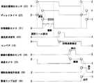
本発明に係る不具合原因究明システム(以下、単に「究明システム」という。)及び不具合原因究明方法の実施の形態につき、図面を参照して説明する。従来技術で説明した構成要素と同一の要素に対しては同一の符号を用いるものとする。図1は、部品実装装置に適用された本実施の形態にかかる究明システム20の全体概要を示している。図において本実施の形態にかかる究明システム20は、部品実装の状況を撮影する状態撮影カメラ21と、回路基板8が実装位置に位置決めされたことを検出する第1の位置検出センサ(実装位置検出センサ)22と、部品実装後に部品が所定通りに実装されたかを検査するための画像を撮像する検査カメラ23と、検査カメラ23による撮像位置を検出する第2の位置検出センサ(撮像位置検出センサ)24と、システム全体を制御するコントローラ25とを備えている。図示の究明システム20では、この他にディレイタイマ27と、リレーボックス28とを備えている。 Embodiments of a failure cause investigation system (hereinafter simply referred to as “investigation system”) and a failure cause investigation method according to the present invention will be described with reference to the drawings. The same reference numerals are used for the same elements as those described in the related art. FIG. 1 shows an overall outline of a
一枚の回路基板8に実装される部品数は多数にのぼり、検査機による検査で、不具合部品が発見される。この不具合部品の発生原因究明のため、本願発明のシステムを用いる。本実施の形態では、対象となる部品を、当該部品11を保持する部品吸着ノズル3を特定することによって特定している。状態撮影カメラ21は、当該対象となる部品吸着ノズル3の部品実装位置を視野に入れる位置に固定され、また検査カメラ23は、部品実装を終えた回路基板8が部品実装直後に搬送される際に前記対象となる部品11を捉える位置に固定されている。部品実装装置1が図5に示すような多機能機の場合であっても、対象部品11が特定されるとその実装位置も特定されることから、状態撮影カメラ21もその実装位置を視野に入れて固定して配置することができる。高速機においては実装位置が予め一定箇所に定められているため、この場合にも状態撮影カメラを固定して配置することができる。 The number of components mounted on one
回路基板8への部品の実装動作は、まず、回路基板8が図1の右側からローダレール13によって部品実装装置内に搬入され、実装テーブル14によって実装位置に規制保持される。直後に回路基板8に対向する位置に移動した部品吸着ノズル3が下降し、部品11を予め定められた実装位置に実装する。部品実装完了の後、部品吸着ノズル3が上昇して退避すると、回路基板8は実装テーブル14さらにアンローダレール15によって部品実装装置外に搬出され、次工程に向けてコンベア16により図の左側へ搬送される。ここで、ローダレール13、実装テーブル14、アンローダレール15は、部品実装装置1に含まれる基板搬送保持部7(図5参照)の構成要素であることが多い。 In the mounting operation of components on the
次に、本実施の形態にかかる究明システム10の動作は、まず回路基板8が実装テーブル14に搬入されて規制保持されたことを実装位置検出センサ22が検出する。実装位置検出センサ22からの信号に基づいて状態撮影カメラ21が起動し、部品実装動作を行う部品吸着ノズル3がその視野に入った時点で、当該ノズル3が撮像対象のノズル3であるかどうかを識別する。対象となっている部品吸着ノズル3であることが識別されると、状態撮影カメラ21は当該部品吸着ノズル3が下降して部品11の実装を行う直前に高速度撮影を開始し、部品実装完了直後にその撮影を完了する。状態撮影カメラ21による撮像対象となる部品吸着ノズル3の識別方法に関しては後述する。 Next, in the operation of the
部品実装動作の1サイクル(部品当たりの実装時間)は、前述した主に小物部品を実装する高速機で約0.1秒、主にQFP等の大型部品を実装する多機能機においても通常は0.5秒内外である。したがって実際に部品吸着ノズル3が部品実装する際の動作を撮影する時間は長くても0.1〜0.3秒ほどとなる。撮影により取得された画像はコントローラ25へ送信される。コントローラ25は限定された記憶容量の記憶部を有しており、例えば5秒分の撮影画像を不具合検査完了時まで一時的に記憶する容量の記憶部を備えていれば、10個分強の部品の実装動作を撮像した画像を記憶することができる。 One cycle of component mounting operation (mounting time per component) is about 0.1 seconds for the high-speed machine that mainly mounts small parts as described above, and usually also for multi-function machines that mainly mount large parts such as QFP. Within 0.5 seconds. Therefore, the time for photographing the operation when the
部品実装を終えた回路基板8を搬送するアンローダレール15、コンベア16の一連の搬送動作は、コントローラ25からの指示に基いて行われ、リレーボックス28がタイミング調整と同期化を図る。この間、コンベア16で搬送中の回路基板8が撮像位置検出センサ24によって検出される。この検出センサ24からの信号に基づいて検査カメラ23が起動し、回路基板8を撮像し、得られた画像をコントローラ25に送信する。コントローラ25は判断部を有しており、この判断部には良品の撮像画像が予め認識されている。前記判断部でこの良品の画像と前記撮像画像とが比較され、部品11が所定通りに実装されており回路基板8が良品であると判断された場合、当該回路基板8は図示しない次工程であるリフロー加熱、又は更なる部品実装に搬送され、必要な加工が施される。 A series of transport operations of the
回路基板8が良品であることが判断されると、先に状態撮影カメラ21により撮影された当該部品に係る実装動作の画像データは不要となり、消去が可能な状態となる。この不要となった画像を一時的に保存していた記憶容量は、次に搬入されて部品実装される回路基板8を撮影するために使用可能な状態となる。より具体的には、例えばコントローラ25から当該画像データに対して消去可能である旨の情報を付加し(フラッグの付与など)、コントローラ25はこの情報を認識することにより、必要に応じて任意のタイミングで当該画像データを消去する。 If it is determined that the
検査カメラ23による撮像結果と予め認識されていた画像との間にアンマッチが見出された場合、コントローラ25の判断部は当該回路基板8が不具合であると判断し、当該回路基板8をライン外に排除するよう指令を出す。この際、コントローラ25は、状態撮影カメラ21から送信されて一時的に保存された撮影画像の内、当該不具合を含む回路基板8の部品実装時における画像を継続して保存する。この保存は、それまで一時的に保存していたコントローラ25の記憶容量をそのまま利用することでも、あるいはコントローラ25自身が備えるCF(compact flash)カードなどの他の記憶媒体や、パーソナルコンピュータなどの外部の記憶手段を利用することでもよい。画像を他の記憶媒体、記憶装置に移し変えた場合、コントローラ25の記憶容量が元の状態に復帰するため、当該容量は以降に部品実装がされる他の回路基板8の実装動作撮影時に利用可能となる。 When an unmatch is found between the imaging result obtained by the inspection camera 23 and the image recognized in advance, the determination unit of the
以上のようにして継続保存された不具合を含む回路基板8の実装時における撮影画像は、その後任意のタイミングで前記記憶媒体/記憶装置から取り出して不具合原因究明に使用することができる。撮影画像を高速度の連続画像としておくことで、実装動作の詳細な分析が可能となり、部品吸着ノズル3が実装動作をする際に部品11が脱落したり、何らかの要因で部品11にずれが生じたり、あるいは部品吸着ノズル3から分離されずにそのまま持ち帰ったりした状況を見出すことができる。 The captured image at the time of mounting the
例えば、部品吸着ノズル3が部品11を持ち帰ったことが不具合原因と分かれば、当該部品吸着ノズル3の先端部分へのクリーム半田などの異物付着、部品吸着ノズル3の先端部分の形状異常、実装時での部品吸着ノズル3からの正圧作動不良など、各種不具合要因が推定可能となり、これらの対策を行うことで更なる不具合の発生を抑制することができる。特定の原因に対する具体的な対応策などを予めマニュアル化してオペレータに配布するなどの処置を講ずれば、より効率的に対策を実施することが可能となる。 For example, if the
なお、不具合製品が発見されたときには、必要に応じて警告ランプを点灯してオペレータに異常を知らせ、あるいは生産ラインをストップする指令をコントローラ25が発信することも可能である。 When a defective product is found, the
図2は、本実施の形態にかかる究明システム20の各要素における動作タイミングチャートを示している。これら全体の動作はコントローラ25によって制御される。図示の各要素において、上方位置にある間は当該要素が動作時であることを示し、下方位置は停止、又は待ち状態にあることを示す。図の上方から順に、まず回路基板8が所定位置に保持されたことを実装位置検出センサ22が検出し、ディレイタイマ27に信号を送る。ディレイタイマ27は所定遅延時間を経過した後、トリガ信号を発して状態撮影カメラ21を起動する。この時間遅延の間に、部品11を保持した部品吸着ノズル3が所定の実装位置まで移動し、回路基板8に向けて下降を開始する。状態撮影カメラ21は当該部品吸着ノズル3が撮影対象となるノズルであるか否かを識別し、撮影対象であることが識別されれば図の斜線部に示すように撮影を開始して当該部品吸着ノズル3による実装動作の連続画像を取得する。 FIG. 2 shows an operation timing chart in each element of the
図3は、撮影対象となる部品11を保持した部品吸着ノズル3を識別するための1例を示している。対象となる部品吸着ノズル3には、図示のような三日月状の識別シール31が貼付されている。この三日月状の識別シール31は、特定の部品吸着ノズル3を識別するための手段の単なる1例であって、その他の形状の識別シール、あるいはシール以外であっても何らかの識別が可能なマークが設けられていれば良い。当該識別シール31の形状はコントローラ25によって予めパターン認識され、コントローラ25は状態撮影カメラ21の認識した識別シール31を前記パターン認識結果と比較することによって当該部品吸着ノズル3が撮像対象であるか否かを識別する。この識別シール31や他の識別マークの形状は、丸や矩形などのごく一般的な形状にした場合には誤認識を生じ易くなり、三日月状などの異形形状を認識パターンに使用することが好ましい。 FIG. 3 shows an example for identifying the
図2に戻って、状態撮影カメラ21は、識別シール31を貼付した部品吸着ノズル3が回路基板8に接近する段階から部品実装を終えて退避するまでの間の実装動作を高速度(例えば100コマ/秒)で撮影し、この撮影された画像をコントローラ25が一時的に保存する。この撮影画像の一時的な保存は基本的に不具合有無の検査時までの間であり、不具合が見出せない時点で保存不要となるものである。状態撮影カメラ21は、撮影が完了すると休止状態に戻り、次の回路基板8を実装位置センサ22が検出したときの信号を受信して再び識別シール31の識別動作ほかの一連の動作を行い、以降これを繰り返す。 Returning to FIG. 2, the
次に、状態撮影カメラ21の撮像(及び、その他全ての部品11の実装)が完了すると、搬送要求信号32がコントローラ25から指令され、ローダレール13、実装テーブル14、アンローダテーブル15、コンベア16が一斉に、若しくは順次に動作して回路基板8を順次搬送する。コンベア16に搬送されて移動中の回路基板8が撮像位置検出センサ24によって検出されると、その信号が検査カメラ23に送信され、当該回路基板8に実装された検査対象となる部品11が通過する瞬間に検査カメラ23が動作してその部品11が実装されている状態を撮像する。 Next, when imaging of the state imaging camera 21 (and mounting of all other components 11) is completed, a transport request signal 32 is commanded from the
前記画像はコントローラ25に送信されて予め記憶された画像と比較され、部品11に位置ずれや欠品などの不具合がなく、正しく実装されているか否かが判断され、正しく実装されていればコンベア16によって次工程へと搬送される。この際、一時的に保存されていた当該回路基板8に係る画像は消去可能とされる。 The image is transmitted to the
一方、部品11の実装に位置ずれや欠品などの不具合が検出されたときは、先に一時的に保存されていた画像を継続保存するための撮影画像保存処理指令23が送られる。また、必要に応じて警報ランプ点灯34などの指令、あるいは操業の一時停止などの指令を発することも可能である。 On the other hand, when a defect such as a positional deviation or a missing part is detected in the mounting of the
図2では一枚の回路基板8に対する特定の部品吸着ノズル3の実装動作に注目して各要素の1サイクル分の動作のみを順次表示したものであって、実際には各要素がそれぞれ連続してこの動作を繰り返している。この際には複数の要素、例えば実装位置検出センサ22と撮像位置検出センサ24とが、それぞれの動作を同時並行して実行している。 In FIG. 2, focusing on the mounting operation of a specific
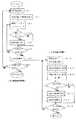
図4は、上述した本実施の形態にかかる不具合原因究明方法を部品実装に適用した場合の手順を示すフローチャートである。図において、左側のフローは実装画像取得段階における手順、右側のフローは不具合検査段階における手順をそれぞれ示している。まず、図の左側の実装画像取得段階において、ステップ#1で部品実装装置1内に回路基板8が搬入され、ステップ#2で実装位置に位置決めされた回路基板8が検出される。所定の遅延時間の後に状態撮影カメラ21が動作し、ステップ#3で三日月状シールなどの識別シール31が貼付された部品吸着ノズル3が検出される。 FIG. 4 is a flowchart showing a procedure when the above-described failure cause investigation method according to the present embodiment is applied to component mounting. In the figure, the left flow shows the procedure in the mounting image acquisition stage, and the right flow shows the procedure in the defect inspection stage. First, in the mounting image acquisition stage on the left side of the drawing, the
ステップ#4で識別シール31が検出されると(Yes)、当該部品吸着ノズル3に保持されている部品11が検査対象であることが識別され、ステップ#5で状態撮影カメラ21により連続画像が取得される。撮影動作が完了すると、ステップ#6で当該回路基板8への全部品実装が完了したかがチェックされ、完了しておれば部品実装段階での手順は完了する。ステップ#4で識別シール31が検出されなければ(No)、ステップ#5の連続画像取得はスキップされて次のステップ#6に進む。これによって状態撮影カメラ21による無駄な動作と記憶容量消費を防いでいる。ステップ#8で全ての回路基板8への実装が未完了であれば、ステップ#1に戻って新たな回路基板8に対して同様な手順が適用される。 If the
次に、図の右側の不具合検査段階において、先のステップ#7での回路基板8の搬送の際、ステップ#10で回路基板8が撮像位置を通過することが検出される。この検出信号を基に、ステップ#11で検査カメラ23により検査対象部品11の実装後の状態が撮像され、ステップ#12で撮像された画像がコントローラ25に送られて予め認識された良品の画像と比較される。ステップ#13で実装不具合が確認されると(Yes)、ステップ#14で事前に撮影されていた画像がコントローラ25の指示によって継続保存され、また、ステップ#15で当該回路基板8は不良として搬送工程外に撤去される。この際、必要であれば警報を発し、あるいは生産ラインを停止することもできる。 Next, in the defect inspection stage on the right side of the drawing, when the
次に、ステップ#16で加工された全ての回路基板8の検査が完了したか否かが判断され、完了していなければステップ#10に戻って次の回路基板10に対してこれまでと同じステップが繰り返される。完了していれば一連の手順は終了する。 Next, it is determined whether or not all the
ステップ#13で不具合が確認されなかった場合(No)、部品実装動作時の画像は保存不要となり、ステップ#14、#15がスキップされてステップ#16に進む。ステップ#14での画像保存がされないために画像は消去可能となり、当該記憶容量は以降の撮影に利用される。不具合原因究明には関係しないため図示されてはいないが、ステップ#13で良品であると判断された回路基板8は、次工程に向けて搬送される。 If no defect is confirmed in step # 13 (No), it is not necessary to save the image during the component mounting operation, and steps # 14 and # 15 are skipped and the process proceeds to step # 16. Since the image is not saved in
以上、本実施の形態の不具合原因究明システム及び不具合検出方法について図5に示すような多機能機の部品実装への適用を例に述べてきたが、勿論、これ以外の適用も可能である。まず、部品実装においてこれまでの説明では回路基板8に実装される多数の部品の内、特定の1部品のみを対象とした不具合発生原因究明を前提としている。このシステムを前述の高速機に適用する場合は、部品吸着ノズルの実装箇所は一定位置であること以外は変わるところは無い。また、撮影画像を一時的に保存するための記憶容量が不十分な場合、オプションとして記憶装置を追加することで対処することができる。この追加の記憶装置は、例えばパーソナルコンピュータとすることができる。状態撮影カメラ21で撮影された画像は順次この追加の記憶装置に送られ、後に良品と判断された場合に画像消却が可能となることはこれまでと同様である。 As described above, the failure cause investigation system and the failure detection method of the present embodiment have been described by taking the application to the component mounting of the multi-function device as shown in FIG. 5 as an example. Of course, other applications are possible. First, in the component mounting, the above description is based on the investigation of the cause of occurrence of a failure for only one specific component among many components mounted on the
次に、これまで述べたシステムでは部品実装段階での動作の記録を、部品実装直後の早い段階で利用可能かどうかを判断するものとしていた。これは不具合原因が発生した後、加工される回路基板8の数が少ない段階で不具合を発見できることから対応が迅速にできて好ましいが、本発明の適用はこれには限定されない。例えば、現在通常行われている最終製品となった段階で不具合を検査するカメラをそのまま使用し、新たに部品実装動作を撮影する状態撮影カメラ21とコントローラ25とを追加して組み合わせて使用することも可能である。この際、中間で搬送される回路基板8の増加により記憶容量が不足するようであれば、上述のオプションのように記憶装置を追加することで対応することができる。 Next, in the system described so far, it is determined whether or not the recording of the operation at the component mounting stage can be used at an early stage immediately after the component mounting. This is preferable because the failure can be found in a stage where the number of
さらに、部品吸着ノズル3による部品実装時の動作を撮影する代わりに、部品吸着ノズル3により部品供給部から部品を吸着して取り出す際の部品取り出し動作を撮像し、検査カメラ23によって不具合が見出された場合に部品取出し段階における不具合発生の原因究明を行うこともできる。また、状態撮影カメラ21、検査カメラ23などの構成要素は、単独ででも使用可能である。例えば、部品実装装置では部品の認識を通常は回路基板8に実装される側の面(裏面)を撮像して行っている。この場合、例えば四角形状のQFPなどの部品では部品吸着ノズル3によってそれが正しい向きに保持されているかは判断できない場合がある。状態撮影カメラ21又は検査カメラ23を利用して部品11の表側の識別標識などを認識することとすれば、この判断を容易にすることができるようになる。 Further, instead of photographing the operation at the time of component mounting by the
部品実装以外の分野においても、例えば複数の要素を搬入して1つの製品に組み付ける自動組み付け装置において不具合原因を究明するため、組み付け動作を撮影可能な位置に状態撮影カメラ21を配置し、組み付け後に搬送されるワークを検出可能な位置に検査カメラ23を配置してコントローラ25と組み合わせて利用してもよい。同様に、例えば多軸自動加工盤で製品を連続高速自動機械加工する場合では、機械加工動作を撮影する位置に状態撮影カメラ21を、加工後の搬送段階に検査カメラ23をそれぞれ配置するなどにより適用することもできる。 In fields other than component mounting, for example, in order to investigate the cause of problems in an automatic assembling apparatus that loads a plurality of elements and assembles them into one product, the
この場合、図3に示す識別シール31のような識別マークは、例えば自動組み付け装置で特定の部品の組み付けを行う組み付け具、あるいは多軸自動盤で特定の加工を行う工具など、特定の加工/組み付け動作を行う対象物に対して貼付することができる。なお、本明細書では、部品実装、組み付け、機械加工などを含めて「加工」と呼ぶものとする。 In this case, an identification mark such as the
以上、及びその他の本発明にかかる不具合原因究明システム/方法の利点をまとめれば以下のようになる。
1.不具合となった製品自身の加工時の動作を遡って分析可能
一時的に保存された画像は不具合製品が加工された時の動作そのものを撮影している。したがって、いつ不具合が発生するか不明な状態で撮影する場合と異なり、無駄な撮影をすることなく有効な不具合発生原因究明が可能となる。
2.限定された記憶容量で連続加工される製品の画像を継続取得可能
加工後の検査で良品であると判断されれば、一時的に保存された画像の消去が可能となる。これを有効活用することによって例えば5秒分程度の僅かな記憶容量で継続した画像取得が可能となる。必要であればオプションの外部記憶装置も利用可能である。
3.システム全体がコンパクト、ポータブルに構成可能
大掛りな専用装置ではなく、既存機器を組み合わせることによってあらゆる装置に容易に取り付け、取り外し可能な構成とすることができる。
4.安価なシステム構成
状態撮影カメラ、検査カメラ、コントローラ、センサはいずれも汎用性のあるものでよい。特に状態撮影カメラは撮影箇所が一定に定まるために固定して使用することができ、極めて簡素な構造のカメラが利用可能である。システム全体で見た場合、例えば専用究明装置を用いる場合と比較すれば数分の1以下のコストに抑えることができる。
5.システムの高い有用性
複数の製品を連続して加工するあらゆる装置への適用が可能である。また、システムの各構成要素を単独で他の用途に使用することもできる。The above and other advantages of the failure cause investigation system / method according to the present invention are summarized as follows.
1. Possible to retrospectively analyze the operation of the defective product itself. The temporarily stored image captures the operation itself when the defective product is processed. Therefore, unlike the case of shooting in a state where it is unknown when a defect occurs, it is possible to investigate the cause of an effective defect without performing unnecessary shooting.
2. It is possible to continuously acquire images of products that are continuously processed with a limited storage capacity. If it is determined that the product is a non-defective product by inspection after processing, the temporarily stored image can be erased. By making effective use of this, it is possible to obtain images continuously with a small storage capacity of, for example, about 5 seconds. An optional external storage device can be used if necessary.
3. The entire system can be configured to be compact and portable. It is not a large-scale dedicated device, but can be easily attached to and detached from any device by combining existing devices.
4). Inexpensive system configuration The state imaging camera, inspection camera, controller, and sensor may all be versatile. In particular, the state photographing camera can be fixedly used because the photographing location is fixed, and a camera with a very simple structure can be used. In terms of the entire system, for example, the cost can be reduced to a fraction of a cost as compared with the case of using a dedicated investigation device.
5. High usability of the system It can be applied to any equipment that processes multiple products in succession. In addition, each component of the system can be used alone for other purposes.
本発明に係る不具合原因究明システムは、例えば部品実装、自動組み付け、自動加工などの、複数の製品を連続して加工、組み付けを行う製造、加工分野において広く利用することができる。 The failure cause investigation system according to the present invention can be widely used in the manufacturing and processing fields in which a plurality of products are continuously processed and assembled, such as component mounting, automatic assembly, and automatic processing.
3.部品吸着ノズル、 7.基板搬送保持部、 8.回路基板、 11.部品、 13.ローダレール、 14.実装テーブル、 15.アンローダレール、 16.コンベア、 20.不具合原因究明システム、 21.状態撮影カメラ、 22.第1の位置検出センサ(実装位置検出センサ)、 23.検査カメラ、 24.第2の位置検出センサ(撮像位置検出センサ)、 25.コントローラ、 27.ディレイタイマ、 28.リレーボックス、 31.識別シール、 32.搬送要求信号、 34.警告ランプ。
3. 6. Parts suction nozzle Substrate transport and holding unit, Circuit board; 11. Parts, 13. Loader rail, 14. Mounting table, 15. Unloader rail, 16. Conveyor, 20. 21. Failure
Claims (18)
Translated fromJapanese各製品の加工時における動作の連続画像を取得して一時的に保存し、
加工後の前記製品の不具合の有無を検査し、
前記検査で不具合が見つからない製品に係る前記一時的に保存された連続画像は消去可能とし、
前記検査で不具合が見つかった製品に係る前記一時的に保存された連続画像は継続保存して不具合原因究明に供し、
前記消去可能となった記憶容量を以降の製品に係る連続画像の取得に利用することによって限定された記憶容量を備えながら連続して加工される複数個の製品の各連続画像を継続して取得可能としたことを特徴とする不具合原因究明方法。A method for investigating the cause of defects when processing multiple products in succession,
Acquire continuous images of operations during processing of each product and store them temporarily.
Inspect for defects in the product after processing,
The temporarily stored continuous images related to products for which no defects are found in the inspection can be erased,
The continuously stored continuous image related to the product found to be defective in the inspection is continuously stored for investigation of the cause of the defect,
Continuous acquisition of each continuous image of a plurality of products processed continuously while having a limited storage capacity by using the erasable storage capacity for acquisition of continuous images related to subsequent products. A method for investigating the cause of a failure characterized by being made possible.
実装位置に回路基板が位置決めされたことを検出し、
実装動作を開始する部品吸着ノズルが撮影対象となる部品吸着ノズルであるかを識別し、
前記部品吸着ノズルが撮影対象であると識別されたときに当該部品吸着ノズルによる部品実装動作を撮像して連続画像を取得し、
前記取得された連続画像を一時的に保存し、
部品実装完了後に搬送される回路基板が撮像位置に到着したことを検出し、
前記回路基板に実装された検査対象となる領域を撮像し、
前記撮像結果と予め入力されていた良品の画像とを比較して不具合の有無を判断し、
前記判断により不具合が発見された場合に前記一時的に保存された当該部品実装時の連続画像を継続保存して不具合原因の究明に提供可能とし、
前記判断により不具合が発見されない場合に前記一時的に保存された連続画像を消去可能として当該記憶容量をそれ以降に加工される製品の実装動作の画像取得に利用する各ステップから構成されることを特徴とする部品実装不具合原因究明方法。A method of investigating the cause of failure when mounting a component on a circuit board using a component suction nozzle,
Detects that the circuit board is positioned at the mounting position,
Identify whether the component suction nozzle that starts the mounting operation is the component suction nozzle to be imaged,
When the component suction nozzle is identified as an imaging target, a component mounting operation by the component suction nozzle is captured to obtain a continuous image,
Temporarily storing the acquired continuous images;
Detects that the circuit board transported after component mounting has arrived at the imaging position,
Image the region to be inspected mounted on the circuit board,
Compare the imaging result with a good image that has been input in advance to determine the presence or absence of defects,
When a defect is found by the determination, it is possible to continuously save a continuous image at the time of mounting the component and provide it for investigation of the cause of the defect,
When no defect is found by the judgment, the temporary storage image is made erasable, and the storage capacity is configured by using each step for acquiring an image of a mounting operation of a product processed thereafter. A method for investigating the cause of component mounting defects.
部品実装時の不具合発生原因を究明するため、請求項8に記載の部品実装不具合原因究明方法を利用することを特徴とする部品実装方法。In the component mounting method of taking out the component supplied to the component supply unit and mounting the component on the mounting position of the circuit board,
A component mounting method characterized by using the component mounting failure cause investigation method according to claim 8 in order to investigate the cause of occurrence of a failure during component mounting.
加工時の動作を撮影可能な位置に固定された状態撮影カメラと、
前記加工時の撮影位置に製品が到達したことを検出する第1の位置検出センサと、
加工後の製品を撮像可能な位置に固定された検査カメラと、
前記加工後の製品が撮像位置に到達したことを検出する第2の位置検出センサと、
全体の動作を制御するコントローラとを備え、
前記コントローラが、
前記状態撮影カメラにより取得された画像を一時的に保存する記憶部と、
前記検査カメラにより撮像された画像を予め入力された良品の画像と比較して当該製品の不具合の有無を判断する判断部とを有し、
前記判断部により不具合製品であると判断された場合、前記記憶部に一時的に保存されている当該製品に係る加工時の画像を継続保存して不具合原因の究明に供するよう構成され、
前記判断部により良品であると判断された場合、前記記憶部に一時的に保存されている当該製品に係る加工時の画像を消去可能とするよう構成されていることを特徴とする不具合原因究明システム。A system for investigating the cause of problems that occur when processing multiple products in succession,
A state shooting camera fixed at a position where the movement at the time of processing can be shot;
A first position detection sensor for detecting that a product has reached the photographing position at the time of processing;
An inspection camera fixed at a position where the processed product can be imaged;
A second position detection sensor for detecting that the processed product has reached the imaging position;
And a controller that controls the overall operation,
The controller is
A storage unit for temporarily storing an image acquired by the state photographing camera;
A determination unit that determines whether there is a defect in the product by comparing an image captured by the inspection camera with a non-defective image input in advance;
When it is determined that the product is a defective product by the determination unit, it is configured to continuously save an image at the time of processing related to the product temporarily stored in the storage unit and to investigate the cause of the failure,
When the determination unit determines that the product is a non-defective product, it is configured to be able to erase the processing image related to the product that is temporarily stored in the storage unit. system.
前記検査カメラが、回路基板に実装後の部品の実装状態を撮像するよう構成され、
前記システムが、部品実装の不具合原因究明に利用可能に構成されていることを特徴とする、請求項10から請求項12のいずれか一に記載の不具合原因究明システム。The state photographing camera is configured to photograph a component mounting operation when a component is mounted on a circuit board,
The inspection camera is configured to image a mounting state of a component after being mounted on a circuit board;
The failure cause investigation system according to any one of claims 10 to 12, wherein the system is configured to be usable for investigation of a cause of failure in component mounting.
The failure cause investigation system according to claim 17, wherein the additional storage device is a personal computer.
Priority Applications (1)
| Application Number | Priority Date | Filing Date | Title |
|---|---|---|---|
| JP2004187669AJP2006013120A (en) | 2004-06-25 | 2004-06-25 | Failure cause investigation system |
Applications Claiming Priority (1)
| Application Number | Priority Date | Filing Date | Title |
|---|---|---|---|
| JP2004187669AJP2006013120A (en) | 2004-06-25 | 2004-06-25 | Failure cause investigation system |
Publications (1)
| Publication Number | Publication Date |
|---|---|
| JP2006013120Atrue JP2006013120A (en) | 2006-01-12 |
Family
ID=35779993
Family Applications (1)
| Application Number | Title | Priority Date | Filing Date |
|---|---|---|---|
| JP2004187669APendingJP2006013120A (en) | 2004-06-25 | 2004-06-25 | Failure cause investigation system |
Country Status (1)
| Country | Link |
|---|---|
| JP (1) | JP2006013120A (en) |
Cited By (12)
| Publication number | Priority date | Publication date | Assignee | Title |
|---|---|---|---|---|
| JP2008098411A (en)* | 2006-10-12 | 2008-04-24 | Juki Corp | Mounting parts inspection method |
| JP2011077095A (en)* | 2009-09-29 | 2011-04-14 | Nec Corp | System, method and program for monitoring facility |
| WO2012111202A1 (en)* | 2011-02-14 | 2012-08-23 | 富士機械製造株式会社 | Component-mounting machine |
| JP2012204455A (en)* | 2011-03-24 | 2012-10-22 | Mitsubishi Electric Corp | Mounting failure analysis system and process abnormality monitoring system |
| JP2014082530A (en)* | 2014-02-14 | 2014-05-08 | Nec Corp | Facility monitoring system, facility monitoring method, and facility monitoring program |
| EP2922380A4 (en)* | 2012-11-13 | 2016-04-20 | Fuji Machine Mfg | DEVICE FOR MONITORING THE STATE OF SUBSTRATE PRODUCTION |
| JP2017058306A (en)* | 2015-09-18 | 2017-03-23 | 日本電気株式会社 | Identification apparatus and identification method |
| JP2018113610A (en)* | 2017-01-12 | 2018-07-19 | ファナック株式会社 | Visual sensor abnormality cause estimation system |
| JP2019129220A (en)* | 2018-01-24 | 2019-08-01 | ヤマハ発動機株式会社 | Component mounting system |
| EP3541161A4 (en)* | 2016-11-14 | 2019-11-27 | Fuji Corporation | MEMORIZED IMAGE RECLASSIFICATION SYSTEM AND RECLASSIFICATION METHOD |
| JP2020167430A (en)* | 2020-06-15 | 2020-10-08 | 株式会社Fuji | Parts mounting machine |
| US11266049B2 (en) | 2015-09-03 | 2022-03-01 | Fuji Corporation | Component mounting machine |
- 2004
- 2004-06-25JPJP2004187669Apatent/JP2006013120A/enactivePending
Cited By (20)
| Publication number | Priority date | Publication date | Assignee | Title |
|---|---|---|---|---|
| JP2008098411A (en)* | 2006-10-12 | 2008-04-24 | Juki Corp | Mounting parts inspection method |
| JP2011077095A (en)* | 2009-09-29 | 2011-04-14 | Nec Corp | System, method and program for monitoring facility |
| CN103314657B (en)* | 2011-02-14 | 2016-05-11 | 富士机械制造株式会社 | Component mounter |
| WO2012111202A1 (en)* | 2011-02-14 | 2012-08-23 | 富士機械製造株式会社 | Component-mounting machine |
| JP2012169394A (en)* | 2011-02-14 | 2012-09-06 | Fuji Mach Mfg Co Ltd | Component mounting device |
| CN103314657A (en)* | 2011-02-14 | 2013-09-18 | 富士机械制造株式会社 | Component-mounting machine |
| DE112011104888B4 (en) | 2011-02-14 | 2025-01-16 | Fuji Corporation | component assembly machine |
| JP2012204455A (en)* | 2011-03-24 | 2012-10-22 | Mitsubishi Electric Corp | Mounting failure analysis system and process abnormality monitoring system |
| US10012970B2 (en) | 2012-11-13 | 2018-07-03 | Fuji Machine Mfg. Co., Ltd. | Board production state monitoring system |
| EP2922380A4 (en)* | 2012-11-13 | 2016-04-20 | Fuji Machine Mfg | DEVICE FOR MONITORING THE STATE OF SUBSTRATE PRODUCTION |
| JP2014082530A (en)* | 2014-02-14 | 2014-05-08 | Nec Corp | Facility monitoring system, facility monitoring method, and facility monitoring program |
| US11266049B2 (en) | 2015-09-03 | 2022-03-01 | Fuji Corporation | Component mounting machine |
| JP2017058306A (en)* | 2015-09-18 | 2017-03-23 | 日本電気株式会社 | Identification apparatus and identification method |
| EP3541161A4 (en)* | 2016-11-14 | 2019-11-27 | Fuji Corporation | MEMORIZED IMAGE RECLASSIFICATION SYSTEM AND RECLASSIFICATION METHOD |
| JP2018113610A (en)* | 2017-01-12 | 2018-07-19 | ファナック株式会社 | Visual sensor abnormality cause estimation system |
| US10497146B2 (en) | 2017-01-12 | 2019-12-03 | Fanuc Corporation | Visual sensor abnormality cause estimation system |
| JP2019129220A (en)* | 2018-01-24 | 2019-08-01 | ヤマハ発動機株式会社 | Component mounting system |
| JP7067938B2 (en) | 2018-01-24 | 2022-05-16 | ヤマハ発動機株式会社 | Component mounting system |
| JP2020167430A (en)* | 2020-06-15 | 2020-10-08 | 株式会社Fuji | Parts mounting machine |
| JP7039654B2 (en) | 2020-06-15 | 2022-03-22 | 株式会社Fuji | Parts mounting machine |
Similar Documents
| Publication | Publication Date | Title |
|---|---|---|
| US20120060357A1 (en) | Part-mounting system and part-mounting method | |
| JP4896655B2 (en) | Mounting fault cause identification method and mounting board manufacturing apparatus | |
| WO2018100717A1 (en) | Manufacturing management system for component mounting line | |
| JP6835878B2 (en) | Production control equipment | |
| JP6301635B2 (en) | Board inspection method | |
| JP2006013120A (en) | Failure cause investigation system | |
| JP2006220426A (en) | Method and system for inspecting mounted electronic component | |
| KR102041277B1 (en) | System for inspecting and modifying PCB soldering | |
| JP6108413B2 (en) | Production monitoring system for component mounting lines | |
| JP2008060249A (en) | Part packaging method and surface mounting machine | |
| US11266049B2 (en) | Component mounting machine | |
| JP4781945B2 (en) | Substrate processing method and component mounting system | |
| JP2012186260A (en) | Component mounting system and component mounting method | |
| JP2007214494A (en) | Mark recognition method and surface mounter | |
| US11943872B2 (en) | Mounting device, mounting system, and inspection/mounting method | |
| JP4481201B2 (en) | Interference detection method and apparatus | |
| JP4672537B2 (en) | Surface mount machine | |
| JP7473735B2 (en) | Foreign object detection device and foreign object detection method | |
| JP4520324B2 (en) | Inspection result notification device and mounting system | |
| JP6904978B2 (en) | Parts mounting machine | |
| US12262476B2 (en) | Mounting device | |
| US12160958B2 (en) | Mounting device and method for controlling mounting device | |
| US20230217637A1 (en) | Component mounting system | |
| JP2019220718A (en) | Component mounting apparatus | |
| JP7286584B2 (en) | mounting machine |
Legal Events
| Date | Code | Title | Description |
|---|---|---|---|
| A621 | Written request for application examination | Free format text:JAPANESE INTERMEDIATE CODE: A621 Effective date:20060613 | |
| A521 | Request for written amendment filed | Free format text:JAPANESE INTERMEDIATE CODE: A821 Effective date:20060829 | |
| RD02 | Notification of acceptance of power of attorney | Free format text:JAPANESE INTERMEDIATE CODE: A7422 Effective date:20060829 | |
| RD04 | Notification of resignation of power of attorney | Free format text:JAPANESE INTERMEDIATE CODE: A7424 Effective date:20060829 | |
| A977 | Report on retrieval | Free format text:JAPANESE INTERMEDIATE CODE: A971007 Effective date:20081226 | |
| A131 | Notification of reasons for refusal | Free format text:JAPANESE INTERMEDIATE CODE: A131 Effective date:20090113 | |
| A521 | Request for written amendment filed | Free format text:JAPANESE INTERMEDIATE CODE: A523 Effective date:20090310 | |
| A131 | Notification of reasons for refusal | Free format text:JAPANESE INTERMEDIATE CODE: A131 Effective date:20090407 | |
| A02 | Decision of refusal | Free format text:JAPANESE INTERMEDIATE CODE: A02 Effective date:20090728 |