JP2006009944A - Quantitative ball valve provided with bias housing - Google Patents
Quantitative ball valve provided with bias housingDownload PDFInfo
- Publication number
- JP2006009944A JP2006009944AJP2004187603AJP2004187603AJP2006009944AJP 2006009944 AJP2006009944 AJP 2006009944AJP 2004187603 AJP2004187603 AJP 2004187603AJP 2004187603 AJP2004187603 AJP 2004187603AJP 2006009944 AJP2006009944 AJP 2006009944A
- Authority
- JP
- Japan
- Prior art keywords
- ball
- axis
- ball valve
- cavity
- housing
- Prior art date
- Legal status (The legal status is an assumption and is not a legal conclusion. Google has not performed a legal analysis and makes no representation as to the accuracy of the status listed.)
- Pending
Links
- 230000013011matingEffects0.000claimsdescription13
- 239000000126substanceSubstances0.000claimsdescription11
- 230000000295complement effectEffects0.000claimsdescription6
- 239000000463materialSubstances0.000claimsdescription6
- 230000009969flowable effectEffects0.000claims2
- 238000007789sealingMethods0.000claims1
- 230000005484gravityEffects0.000description2
- 239000011236particulate materialSubstances0.000description2
- 235000004522Pentaglottis sempervirensNutrition0.000description1
- 240000004050Pentaglottis sempervirensSpecies0.000description1
- 230000006835compressionEffects0.000description1
- 238000007906compressionMethods0.000description1
- 230000007812deficiencyEffects0.000description1
- 238000001746injection mouldingMethods0.000description1
- 239000007788liquidSubstances0.000description1
- 230000004048modificationEffects0.000description1
- 238000012986modificationMethods0.000description1
- 239000013618particulate matterSubstances0.000description1
- 239000000843powderSubstances0.000description1
- 239000002002slurrySubstances0.000description1
- 239000007787solidSubstances0.000description1
- 239000011343solid materialSubstances0.000description1
Images


Landscapes
- Valve Housings (AREA)
- Taps Or Cocks (AREA)
Abstract
Description
Translated fromJapanese本発明は、単位体積を分配する定量ボールバルブ、及び、より具体的には、弾性スプリットハウジング内に収納される際のそのようなボールバルブに関する。The present invention relates to a metered ball valve that dispenses a unit volume, and more particularly to such a ball valve when housed in an elastic split housing.
定量ボールバルブは、ハウジング内のボールバルブの回転によって、ボール中の止まり穴が、分配する物質を受ける位置から、受けた物質を分配可能な別の位置に移動することができるものとして知られている。A metered ball valve is known to allow a blind hole in the ball to move from a location that receives the material to be dispensed to another location where the received material can be dispensed by rotation of the ball valve in the housing. Yes.
従来公知のボールバルブには、特に粒状物質を分配するのに使用した際に、ボールの表面に付着してしまう物質があるとボールの回転が妨げられて、詰まり状態が生じ得るという欠点があった。このような状態は、特に、分配する物質がボールに対して粘着性であったり又は融合し得る粒状物質や、加湿条件下等で吸湿する粒状物質を含んでいる場合に起こり得る。The conventionally known ball valves have the disadvantage that, when used to dispense particulate material, if there is a substance that adheres to the surface of the ball, the rotation of the ball is hindered and a clogged state may occur. It was. Such a situation can occur particularly when the substance to be dispensed contains a granular substance that is sticky to the ball or can be fused, or a granular substance that absorbs moisture under humidified conditions.
従来公知の装置が持つこれらの欠点を、少なくとも部分的に克服するために、本発明は、ハウジンクが、弾性的にともに傾けられる2つの相補的な半部材であってお互いから分離するように調整されたものからなる分配用ボールバルブを提供する。In order to overcome, at least in part, these deficiencies of previously known devices, the present invention is arranged so that the housing is two complementary halves that are elastically tilted together and separate from each other. Distributing ball valves are provided.
本発明の目的は、改良された分配用ボールバルブを提供することである。It is an object of the present invention to provide an improved dispensing ball valve.
本発明の他の目的は、ボールを内部に収納するハウジングが、弾性的にともに傾けられる2つの相補的な半部材であってその傾きに対してお互いから分離するように調整されたものからなる分配用ボールバルブを提供することである。Another object of the present invention is that the housing housing the ball is composed of two complementary half members that are elastically tilted together and adjusted to separate from each other with respect to the tilt. It is to provide a ball valve for dispensing.
1つの態様において、本発明は、
ハウジングが内部球形キャビティを有し、第一ポートが上記ハウジングの第一側面から上記キャビティへと開き、第二ポートが上記ハウジングの第二反対側面から上記キャビティへと開いており、
ボールが、上記球形キャビティの中心を貫く第一軸の周りを回転するよう、上記キャビティ内で上記ハウジングに同心的に収納されており、
上記ボールは、上記キャビティ内部で密閉連結のため、球形外表面を有しており、
上記ボールは、容積が分かっている止まり穴を有しており、
上記ボールは、上記止まり穴が上記第一ポートと連関する第一の位置と、上記止まり穴が上記第二ポートと連関する第二の位置との間で、上記第一軸の周りを回転するよう調整されており、
上記ボールの上記球形外表面と上記キャビティとの間の上記密閉連結は、上記第一の位置と上記第二の位置との間で上記ボールが回転するあいだ維持されることによって、上記第一の位置と上記第二の位置との間での上記ボールの回転が、上記第一ポートとの連関から上記第二ポートとの連関へと所定の体積を動かすよう調整されており、
上記ハウジングは相補的な2つの半部材からなり、第一半部材が上記第一ポートを有し、第二半部材が上記第二ポートを有し、各半部材は上記キャビティのおよそ半分を有しており、
上記第一及び第二半部材は互いに組み合わされてそのあいだに上記キャビティを形成し、上記第一半部材における全般的に水平な第一合わせ面が、上記第二半部材の全般的に水平な第二合わせ面と、回転可能かつ密閉可能な状態で連結するよう調整されており、
バイアス機構が上記第一及び第二半部材をともに弾性的に傾けて、上記全般的に水平な第一合わせ面を上記全般的に水平な第二合わせ面と密閉連結させ、
上記第一及び第二半部材は、上記バイアス機構の傾きに対してそれらの水平な合わせ面で互いから分離するよう調整されている
ことからなるボールバルブを提供する。In one aspect, the present invention provides:
The housing has an internal spherical cavity, the first port opens from the first side of the housing to the cavity, and the second port opens from the second opposite side of the housing to the cavity;
A ball is concentrically housed in the housing within the cavity such that the ball rotates about a first axis through the center of the spherical cavity;
The ball has a spherical outer surface for hermetic connection within the cavity,
The ball has a blind hole with a known volume,
The ball rotates about the first axis between a first position where the blind hole is associated with the first port and a second position where the blind hole is associated with the second port. Has been adjusted so that
The hermetic connection between the spherical outer surface of the ball and the cavity is maintained during rotation of the ball between the first position and the second position, whereby the first The rotation of the ball between a position and the second position is adjusted to move a predetermined volume from an association with the first port to an association with the second port;
The housing comprises two complementary half members, the first half member having the first port, the second half member having the second port, and each half member having approximately half of the cavity. And
The first and second half members are combined together to form the cavity therebetween, and a generally horizontal first mating surface in the first half member is generally horizontal in the second half member. It is adjusted to connect with the second mating surface in a rotatable and sealable state,
A biasing mechanism elastically tilts both the first and second half members to hermetically connect the generally horizontal first mating surface with the generally horizontal second mating surface;
The first and second half members provide a ball valve that is adjusted to separate from each other at their horizontal mating surfaces against the tilt of the bias mechanism.
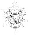
まず定量ボールバルブ10の第一態様を示した図1〜4を参照する。ボールバルブ10は、上部半部材14及び下部半部材16から構成されたバルブ本体12、並びに、ボール20を持つものとして示される。バルブ本体12はその中心に球形キャビティ18を有しており、その内部で、ボール20が、ボールから軸11と同軸的に伸びる円筒形スタブアクスル22及び24によって、軸11を回転可能にジャーナルされる。軸11は球形キャビティ18の中心26を貫いている。スタブアクスル22及び24は、軸11と同軸的な円筒形アクスル座面28及び30において回転可能にジャーナルされている。座面28及び30それぞれの半分は、半部材14及び16それぞれに形成される。Reference is first made to FIGS. 1 to 4 showing a first embodiment of the
バルブ本体12は、上部半部材14を通る入口通路32をその上部に、下部半部材16を通る出口通路34をその下部に有する。ボール20は、バルブ本体12内の球形キャビティ18内部に配置される。ボール20は、球形キャビティ18の中心26を貫く軸40の周りに、軸11と垂直に形成された円筒形止まり穴36を有する。止まり穴36はひとつの止まり末端38で閉じられ、他方の止まり末端40で開口している。ボール20は、半部材14及び16を通る円筒形座面28及び30にジャーナルされているボール20の反対側における円筒形スタブアスクル22及び24のために半部材14及び16の間でジャーナルされるよう軸11の周りを回転するよう配置される。円筒形スタブ部材14のひとつはキーホールを有しており、これはシャフト44を受けてボール20を回転するよう調整される。The valve body 12 has an inlet passage 32 through the
ボール20は、図2で示したように充填又は受け止め位置から回転可能である。ここで、ボール20内の穴36はホッパ43に向けて開かれ、固体物質44等の、ホッパ43内にある物質44は、重力によって、入口通路32を通って落下し、ボール20内部の穴36を充填することができる。この位置から、ボール20は図3で示したように、供給又は分配位置へと軸11に沿って回転することができる。ここで、ボール20はホッパ43との連関を閉じ、ボール20内の穴36はバルブ本体12の外へ出口通路34に向けて開口することによって、ボール20の穴36内に受け止められている物質44が重力下で分配される。このように、モーター又は手動等でシャフト44によりボールが回転することによって、ボール20はホッパ43から物質44を受け止め、次にこれを分配するものと理解されたい。The
ボール20とバルブ本体12とのあいだを密閉させるために、上部及び下部の2つのOリング46及び48は、Oリングが連結する入口通路32及び出口通路34それぞれについて軸40と同軸的に配置され、ボール20の外部球面50と、キャビティ18の内部球面52とのあいだでシールを形成する。Oリング46及び48は、キャビティ18の内部球面52に形成された溝に収められる。In order to seal between the
バルブ本体12は、ハウジングの片面にひとつずつ2つの外部突起54及び56を有する。各突起54及び56は、軸11及び軸40のそれぞれに対して垂直な軸58と同軸的に配置される。各突起の上半分54a及び56aは上部半部材14の一部からなり、各突起の下半分54b及び56bは下部半部材16の一部からなる。図で示すように、突起54と56はともに、軸58と同軸的に配置された円筒形部材からなり、各突起の上半分54a及び56aは、一般に断面が半円形の部材からなり、同じく断面が半円形である各突起の下半分54b及び56bとかみ合っている。突起54及び56それぞれは、軸58からの半径に対してそれぞれ垂直に向いた円形肩面55及び57を与える。この点で、環状溝が、軸58に対して垂直に向いた円形肩面における各突起54及び56の周りに設けられる。The valve body 12 has two
2つの弾性Oリング60及び62が、突起54及び56それぞれに対して環状溝内に取り付けられることによって、Oリングそれぞれが円形肩面に連結し、圧縮下で第一及び第二半部材14及び16をともに傾けることになる。Two elastic O-
示される好ましい態様では、突起54及び56の周りに収納されることで半部材14及び16をともに動かすOリング60及び62は、ボール20とキャビティ18とのあいだに配置されたOリング46及び48と同じ大きさのものである。In the preferred embodiment shown, O-
突起54及び56の周りに配置されたOリング60及び62の大きさは、その周りがしっかりと固定され、かつ、第一及び第二半部材14及び16を一緒に傾けて、上部半部材14上にある全般的に水平な第一合わせ面64を、下部半部材16上にある全般的に水平な第二合わせ面66と実質的な密閉連結させるようなものである。The size of the O-
上部及び下部半部材14及び16が弾性的にともに傾けられるという事実には、潜在的な詰まり状態で起こり得るものとして、ボール20又は半部材14及び16に生じる損傷というよりは、例えば粒状物質44の粒子が、ボール20を回転させた際にボール20の外部球面50に付着した場合に、付着した物質によって事実上引き延ばされた半径を持つボール20の回転によって、バルブ本体12の2つの半部材14及び16が弾性Oリング60及び62の傾きに対して離れて広がるという利点がある。The fact that the upper and
本発明の分配用ボールバルブは、特に、ホッパ43から粒状物質を分配する際の使用に向けられたものである。シャフト44は、好ましくは、なんらかの回転用機械的機構によって、単位体積の物質44を分配するのが望まれる時であればいつでも、連続的に、又は、より典型的には周期的に回される。好ましい回転モーターとしては、例えば、正確に制御されたステップ電気モーター等の電気機械的装置であってよい。あるいは、好ましいモーターとしては、空気圧で駆動する空気モーターからなるものでもよく、これにはボールの回転に逆らう力が大きすぎる場合に失速するという利点がある。The dispensing ball valve of the present invention is particularly directed to use when dispensing particulate material from the
本発明の分配用ボールバルブが特に粒状固体物質及び粉末を分配するのに使用できるよう調整されるが、この装置は液体及びスラリーを分配するのにも有用である。Although the dispensing ball valve of the present invention is specifically tailored for use in dispensing particulate solid materials and powders, the apparatus is also useful for dispensing liquids and slurries.
必要ではないが、ボール20がバルブ本体12内で正しい位置に確実に向くよう補助するために、スタブアクスル22及び24は異なる直径を持つことが好ましい。Although not required, it is preferred that the
次に、射出成形の際のように各種成分を形成させるように調整される際の、本発明の分配用ボールバルブ10の第二態様を示した図5、6及び7を参照する。Reference is now made to FIGS. 5, 6 and 7 showing a second embodiment of the dispensing
図6では、簡略化のためにOリング60及び62を示していない。図6は、バルブ半部材14及び16上で突起54及び56の周りに固定されたOリング60及び62を示す。In FIG. 6, O-
スタブアクスル22にはその末端において、ボール20の相関的位置を指し示す矢印70が示されている。スタブアクスル22の末端周りのバルブ本体12の外部側面には、ボールバルブが受け止め「FILL(充填)」位置にあるか、又は、分配「FEED(供給)」位置にあるか、又は、2つのあいだの、分配が生じ得ない「REST(休止)」位置にあるかを示す印が与えられる。第二の態様は、ボール20を通常REST位置に維持しておくが、供給物を分配したいときにはまずFILL位置に動かして充填し次にFEED位置に動かして分配するというように、ボールをFILL位置とFEED位置とのあいだの180度を単に回転させるという使用に向けて調整されてもよい。分配後、バルブの再度の使用が望まれるまで、物質をREST位置に動かす。The
本発明を好ましい態様を参照して開示したが、当業者は数多くの変更や変形を想起しよう。本発明の定義のために、添付の請求の範囲を参照する。Although the present invention has been disclosed with reference to preferred embodiments, many modifications and variations will occur to those skilled in the art. For the definition of the invention, reference is made to the appended claims.
10、定量ボールバルブ
11、軸
12、バルブ本体
14、上部半部材
16、下部半部材
18、球形キャビティ
20、ボール
22及び24、円筒形スタブアクスル
26、球形キャビティ18の中心
28及び30、円筒形アクスル座面
32、入口通路
34、出口通路
36、円筒形止まり穴
38、止まり末端
40、他方の止まり末端
40、中心26を貫く軸
43、ホッパ
44、シャフト
44、物質
46及び48、Oリング
50、ボール20の外部球面
52、キャビティ18の内部球面
54及び56、外部突起
54a及び56a、各突起の上半分
54b及び56b、各突起の下半分
55及び57、円形肩面
58、軸
60及び62、Oリング
64、全般的に水平な第一合わせ面
66、全般的に水平な第二合わせ面
70、矢印10, metering ball valve 11, shaft 12,
Claims (14)
Translated fromJapaneseボールが、前記球形キャビティの中心を貫く第一軸の周りを回転するよう、前記キャビティ内で前記ハウジングに同心的に収納されており、
前記ボールは、前記キャビティ内部で密閉連結のため、球形外表面を有しており、
前記ボールは、容積が分かっている止まり穴を有しており、
前記ボールは、前記止まり穴が前記第一ポートと連関する第一の位置と、前記止まり穴が前記第二ポートと連関する第二の位置との間で、前記第一軸の周りを回転するよう調整されており、
前記ボールの前記球形外表面と前記キャビティとの間の前記密閉連結は、前記第一の位置と前記第二の位置との間で前記ボールが回転するあいだ維持されることによって、前記第一の位置と前記第二の位置との間での前記ボールの回転が、前記第一ポートとの連関から前記第二ポートとの連関へと所定の体積を動かすよう調整されており、
前記ハウジングは相補的な2つの半部材からなり、第一半部材が前記第一ポートを有し、第二半部材が前記第二ポートを有し、各半部材は前記キャビティのおよそ半分を有しており、
前記第一及び第二半部材は互いに組み合わされてそのあいだに前記キャビティを形成し、前記第一半部材における全般的に水平な第一合わせ面が、前記第二半部材の全般的に水平な第二合わせ面と、回転可能かつ密閉可能な状態で連結するよう調整されており、
バイアス機構が前記第一及び第二半部材をともに弾性的に傾けて、前記全般的に水平な第一合わせ面を前記全般的に水平な第二合わせ面と密閉連結させる
ことからなることを特徴とするボールバルブ。The housing has an internal spherical cavity, the first port opens from the first side of the housing to the cavity, and the second port opens from the second opposite side of the housing to the cavity;
A ball is concentrically housed in the housing within the cavity for rotation about a first axis through the center of the spherical cavity;
The ball has a spherical outer surface for hermetic connection within the cavity;
The ball has a blind hole of known volume;
The ball rotates about the first axis between a first position where the blind hole is associated with the first port and a second position where the blind hole is associated with the second port. Has been adjusted so that
The hermetic connection between the spherical outer surface of the ball and the cavity is maintained during rotation of the ball between the first position and the second position, whereby the first The rotation of the ball between a position and the second position is adjusted to move a predetermined volume from an association with the first port to an association with the second port;
The housing comprises two complementary half members, the first half member having the first port, the second half member having the second port, and each half member having approximately half of the cavity. And
The first and second half members are combined together to form the cavity therebetween, and a generally horizontal first mating surface in the first half member is generally horizontal in the second half member. It is adjusted to connect with the second mating surface in a rotatable and sealable state,
A biasing mechanism comprises elastically tilting the first and second half members together to hermetically connect the generally horizontal first mating surface with the generally horizontal second mating surface. And ball valve.
各突起は2つの半突起からなり、各突起の第一半突起は第一半部材の一部からなり、各突起の第二半突起は第二半部材の一部からなり、
バイアス機構は2つの弾性環状リングからなり、ひとつのリングはそれぞれの突起の第一及び第二半突起双方における円形肩の部分を連結する突起それぞれに積載されており、それぞれの突起の第一及び第二半突起を動かすことによって、2つの半部材をともに動かすものである
請求項1記載のボールバルブ。The housing has two external protrusions, one on each side of the housing, each protrusion arranged coaxially with a second axis passing through the center of the spherical cavity, and a circular shoulder oriented perpendicular to the radius from the axis. Giving a surface,
Each projection consists of two half projections, the first half projection of each projection consists of a part of the first half member, the second half projection of each projection consists of a part of the second half member,
The biasing mechanism consists of two elastic annular rings, one ring being mounted on each of the projections connecting the circular shoulder portions in both the first and second half projections of each projection, 2. The ball valve according to claim 1, wherein the two half members are moved together by moving the second half projection.
請求項1記載のボールバルブ。2. The ball valve according to claim 1, wherein an opening is formed in the cavity coaxially with the first shaft, and through this, the ball and an external mechanism of the ball valve for rotating the ball about the shaft are connected. .
請求項3記載のボールバルブ。4. The ball valve according to claim 3, wherein the opening has a journal surface coaxially with an axis for journaling the ball for rotation about the first axis.
各スタブアクスルは第一軸と同軸に外部ジャーナル面を有し、
ハウジングは、第一軸と同軸にハウジングの片面にひとつずつ2つのアクシルベアリングを有し、これらはスタブアクスル上の外部ジャーナル面と相補的に、第一軸と同軸にジャーナル面を与えるもので、第一軸を中心とした回転のためにハウジング内にボールをジャーナルするためそれに連結するものであり、
各アクシルベアリングは2つの半ベアリングを有し、各アクシルベアリングの第一半ベアリングは第一半部材の一部からなり、各アクシルベアリングの第二半ベアリングは第二半部材の一部からなる
請求項1記載のボールバルブ。The ball has a spherical nucleus and two stub axles, one on each side of the nucleus, extending outward from the nucleus coaxially with the first axis,
Each stub axle has an external journal surface coaxial with the first axis,
The housing has two axle bearings, one on one side of the housing, coaxial with the first axis, which provide a journal surface coaxial with the first axis, complementary to the external journal surface on the stub axle, Connected to journal the ball in the housing for rotation about the first axis,
Each axle bearing has two half bearings, wherein the first half bearing of each axle bearing consists of a part of the first half member and the second half bearing of each axle bearing consists of a part of the second half member Item 1. A ball valve according to Item 1.
各スタブアクスルは第一軸と同軸に外部ジャーナル面を有し、
各突起は、上記軸と同軸にキャビティ内に開口部を有し、スタブアクスル上の外部ジャーナル面と相補的に、第一軸と同軸にジャーナル面を与えるもので、第一軸を中心とした回転のためにハウジング内にボールをジャーナルするためそれに連結するものである
請求項2記載のボールバルブ。The ball has a spherical nucleus and two stub axles, one on each side of the nucleus, extending outward from the nucleus coaxially with the first axis,
Each stub axle has an external journal surface coaxial with the first axis,
Each protrusion has an opening in the cavity coaxially with the above-mentioned axis, and gives a journal surface coaxially with the first axis, complementary to the external journal surface on the stub axle, and is centered on the first axis. 3. A ball valve according to claim 2, wherein the ball valve is coupled to journal the ball within the housing for rotation.
請求項6記載のボールバルブ。The ball valve according to claim 6, wherein the first stub axle has an outer journal surface having a radius different from a radius of the outer journal surface of the second stub axle.
請求項7記載のボールバルブ。The ball valve according to claim 7, wherein the surface of each protrusion has a circular cross section with the second axis as the center.
ボールを連結して、軸周りのボールの回転時にそれでシールを形成する
請求項1記載のボールバルブ。The cavity has a spherical inner surface, and the two elastic O-rings are respectively disposed on the side surfaces of the first port and the second port, in the respective recesses of the spherical inner surface around the first axis,
2. The ball valve of claim 1, wherein the balls are connected to form a seal when the balls are rotated about the axis.
ボールを連結して、軸周りのボールの回転時にそれでシールを形成し、
2つの弾性Oリング及び2つのシーリングリングは交換可能である
請求項2記載のボールバルブ。The cavity has a spherical inner surface, and the two elastic O-rings are respectively disposed on the side surfaces of the first port and the second port, in the respective recesses of the spherical inner surface around the first axis,
Connect the balls and form a seal with it when the ball rotates around its axis,
The ball valve according to claim 2, wherein the two elastic O-rings and the two sealing rings are interchangeable.
請求項1記載のボールバルブ。The ball valve according to claim 1, further comprising a mechanism for rotating the ball between the first position and the second position.
請求項11記載のボールバルブ。The ball valve according to claim 11, wherein a mechanism for rotating the ball includes a score on the ball adjusted to be coupled by a shaft.
これによって第一の位置から第二の位置に至るボールの回転が、前記第一容器から前記出口に所定量の前記物質を移動させる
請求項1記載のボールバルブ。The first end is associated with a first container containing a flowable substance, the second end is associated with an outlet,
The ball valve according to claim 1, wherein the rotation of the ball from the first position to the second position thereby moves a predetermined amount of the substance from the first container to the outlet.
これによって、第一の位置から第二の位置に至るボールの回転が、前記第一容器から前記第二容器に、止まり穴の容積に等しい所定量の物質を移動させる
請求項1記載のボールバルブ。The first end is associated with a first container containing a first flowable substance, the second end is associated with a second container,
2. The ball valve according to claim 1, wherein the rotation of the ball from the first position to the second position moves a predetermined amount of material equal to the volume of the blind hole from the first container to the second container. .
Priority Applications (1)
| Application Number | Priority Date | Filing Date | Title |
|---|---|---|---|
| JP2004187603AJP2006009944A (en) | 2004-06-25 | 2004-06-25 | Quantitative ball valve provided with bias housing |
Applications Claiming Priority (1)
| Application Number | Priority Date | Filing Date | Title |
|---|---|---|---|
| JP2004187603AJP2006009944A (en) | 2004-06-25 | 2004-06-25 | Quantitative ball valve provided with bias housing |
Publications (1)
| Publication Number | Publication Date |
|---|---|
| JP2006009944Atrue JP2006009944A (en) | 2006-01-12 |
Family
ID=35777419
Family Applications (1)
| Application Number | Title | Priority Date | Filing Date |
|---|---|---|---|
| JP2004187603APendingJP2006009944A (en) | 2004-06-25 | 2004-06-25 | Quantitative ball valve provided with bias housing |
Country Status (1)
| Country | Link |
|---|---|
| JP (1) | JP2006009944A (en) |
Cited By (8)
| Publication number | Priority date | Publication date | Assignee | Title |
|---|---|---|---|---|
| JP2008122115A (en)* | 2006-11-09 | 2008-05-29 | Suzumo Machinery Co Ltd | Dried food measuring/dividing apparatus |
| WO2010033634A3 (en)* | 2008-09-16 | 2010-05-20 | Tandem Diabetes Care, Inc. | Flow regulating stopcocks and related methods |
| US8287495B2 (en) | 2009-07-30 | 2012-10-16 | Tandem Diabetes Care, Inc. | Infusion pump system with disposable cartridge having pressure venting and pressure feedback |
| KR101328040B1 (en)* | 2011-12-09 | 2013-11-13 | 글로벌 엔지니어링 테크놀로지 피티이. 엘티디. | Catalyst supply |
| US8986253B2 (en) | 2008-01-25 | 2015-03-24 | Tandem Diabetes Care, Inc. | Two chamber pumps and related methods |
| CN106610308A (en)* | 2016-01-26 | 2017-05-03 | 江苏润仪仪表有限公司 | Liquid flowmeter of fixed-quantity push type |
| US9962486B2 (en) | 2013-03-14 | 2018-05-08 | Tandem Diabetes Care, Inc. | System and method for detecting occlusions in an infusion pump |
| US10258736B2 (en) | 2012-05-17 | 2019-04-16 | Tandem Diabetes Care, Inc. | Systems including vial adapter for fluid transfer |
- 2004
- 2004-06-25JPJP2004187603Apatent/JP2006009944A/enactivePending
Cited By (14)
| Publication number | Priority date | Publication date | Assignee | Title |
|---|---|---|---|---|
| JP2008122115A (en)* | 2006-11-09 | 2008-05-29 | Suzumo Machinery Co Ltd | Dried food measuring/dividing apparatus |
| US8986253B2 (en) | 2008-01-25 | 2015-03-24 | Tandem Diabetes Care, Inc. | Two chamber pumps and related methods |
| WO2010033634A3 (en)* | 2008-09-16 | 2010-05-20 | Tandem Diabetes Care, Inc. | Flow regulating stopcocks and related methods |
| US11135362B2 (en) | 2009-07-30 | 2021-10-05 | Tandem Diabetes Care, Inc. | Infusion pump systems and methods |
| US8287495B2 (en) | 2009-07-30 | 2012-10-16 | Tandem Diabetes Care, Inc. | Infusion pump system with disposable cartridge having pressure venting and pressure feedback |
| US8926561B2 (en) | 2009-07-30 | 2015-01-06 | Tandem Diabetes Care, Inc. | Infusion pump system with disposable cartridge having pressure venting and pressure feedback |
| US9211377B2 (en) | 2009-07-30 | 2015-12-15 | Tandem Diabetes Care, Inc. | Infusion pump system with disposable cartridge having pressure venting and pressure feedback |
| US12144964B2 (en) | 2009-07-30 | 2024-11-19 | Tandem Diabetes Care, Inc | Infusion pump system with disposable cartridge having pressure venting and pressure feedback |
| US12042627B2 (en) | 2009-07-30 | 2024-07-23 | Tandem Diabetes Care, Inc. | Infusion pump systems and methods |
| US11285263B2 (en) | 2009-07-30 | 2022-03-29 | Tandem Diabetes Care, Inc. | Infusion pump systems and methods |
| KR101328040B1 (en)* | 2011-12-09 | 2013-11-13 | 글로벌 엔지니어링 테크놀로지 피티이. 엘티디. | Catalyst supply |
| US10258736B2 (en) | 2012-05-17 | 2019-04-16 | Tandem Diabetes Care, Inc. | Systems including vial adapter for fluid transfer |
| US9962486B2 (en) | 2013-03-14 | 2018-05-08 | Tandem Diabetes Care, Inc. | System and method for detecting occlusions in an infusion pump |
| CN106610308A (en)* | 2016-01-26 | 2017-05-03 | 江苏润仪仪表有限公司 | Liquid flowmeter of fixed-quantity push type |
Similar Documents
| Publication | Publication Date | Title |
|---|---|---|
| US6766924B1 (en) | Metering ball-valve with biased housing | |
| AU2011347477B2 (en) | System of a container for storing and dispensing a product and a machine for dosing the product | |
| JP2006009944A (en) | Quantitative ball valve provided with bias housing | |
| ES2895671T3 (en) | hygienic mixer | |
| JPH0534201B2 (en) | ||
| WO2010106282A1 (en) | Mixing container comprising a shaft bearing in the upper part | |
| EP2254687A1 (en) | Mixing vessel | |
| JP2009075087A (en) | Dosage-dispensing device and dosage-dispensing unit with electrostatic closure device | |
| EP1033332B1 (en) | Powder grain material control unit and powder grain material filling unit comprising such a unit | |
| EP0754278A1 (en) | Valve system | |
| EP1851150A1 (en) | Device for distribution of at least one granular product in a container filling device and method for filling using such a device | |
| JP5431718B2 (en) | Feeding device for transporting a powdered medium from a powder container to a powder conduit | |
| US10228077B2 (en) | Fluidizing butterfly valve, and system | |
| US10976189B1 (en) | Measuring and dispensing device | |
| CN116096270A (en) | Hybrid systems and methods | |
| US6971554B2 (en) | Device for the controlled distribution of pulverulent products | |
| KR101977847B1 (en) | Mixer | |
| US9958307B1 (en) | Chemical dosing system | |
| CA2649957A1 (en) | Substance stirring device | |
| JP3520230B2 (en) | Manure spreader | |
| JP2650798B2 (en) | Movable chute for crusher | |
| JP4705213B2 (en) | Discharge device | |
| CN201107562Y (en) | Developing agent loading equipment for laser printer powder box | |
| JP2016210491A (en) | Spherical object supply container | |
| JP2000346212A (en) | Discharge valve for liquid container |