JP2006009596A - Wind power generator with built-in transformation switch gear, and its construction method - Google Patents
Wind power generator with built-in transformation switch gear, and its construction methodDownload PDFInfo
- Publication number
- JP2006009596A JP2006009596AJP2004183907AJP2004183907AJP2006009596AJP 2006009596 AJP2006009596 AJP 2006009596AJP 2004183907 AJP2004183907 AJP 2004183907AJP 2004183907 AJP2004183907 AJP 2004183907AJP 2006009596 AJP2006009596 AJP 2006009596A
- Authority
- JP
- Japan
- Prior art keywords
- transformer
- switchgear
- tower
- gantry
- opening
- Prior art date
- Legal status (The legal status is an assumption and is not a legal conclusion. Google has not performed a legal analysis and makes no representation as to the accuracy of the status listed.)
- Pending
Links
- 238000010276constructionMethods0.000titleclaimsabstractdescription15
- 230000009466transformationEffects0.000titleabstractdescription8
- 238000007689inspectionMethods0.000claimsabstractdescription18
- 230000005540biological transmissionEffects0.000claimsdescription10
- 230000001681protective effectEffects0.000claimsdescription5
- 238000000034methodMethods0.000claimsdescription4
- 230000003028elevating effectEffects0.000claimsdescription3
- 238000009413insulationMethods0.000description13
- 238000009434installationMethods0.000description6
- 238000010248power generationMethods0.000description3
- 239000007787solidSubstances0.000description3
- 238000005452bendingMethods0.000description2
- 230000005611electricityEffects0.000description2
- 230000005484gravityEffects0.000description2
- 238000012423maintenanceMethods0.000description2
- NJPPVKZQTLUDBO-UHFFFAOYSA-NnovaluronChemical compoundC1=C(Cl)C(OC(F)(F)C(OC(F)(F)F)F)=CC=C1NC(=O)NC(=O)C1=C(F)C=CC=C1FNJPPVKZQTLUDBO-UHFFFAOYSA-N0.000description2
- 229920001342Bakelite®Polymers0.000description1
- 239000004637bakeliteSubstances0.000description1
- 230000007423decreaseEffects0.000description1
- 238000005516engineering processMethods0.000description1
- 239000002184metalSubstances0.000description1
- 230000003014reinforcing effectEffects0.000description1
- 239000012779reinforcing materialSubstances0.000description1
Images


Classifications
- Y—GENERAL TAGGING OF NEW TECHNOLOGICAL DEVELOPMENTS; GENERAL TAGGING OF CROSS-SECTIONAL TECHNOLOGIES SPANNING OVER SEVERAL SECTIONS OF THE IPC; TECHNICAL SUBJECTS COVERED BY FORMER USPC CROSS-REFERENCE ART COLLECTIONS [XRACs] AND DIGESTS
- Y02—TECHNOLOGIES OR APPLICATIONS FOR MITIGATION OR ADAPTATION AGAINST CLIMATE CHANGE
- Y02E—REDUCTION OF GREENHOUSE GAS [GHG] EMISSIONS, RELATED TO ENERGY GENERATION, TRANSMISSION OR DISTRIBUTION
- Y02E10/00—Energy generation through renewable energy sources
- Y02E10/70—Wind energy
- Y02E10/72—Wind turbines with rotation axis in wind direction
- Y—GENERAL TAGGING OF NEW TECHNOLOGICAL DEVELOPMENTS; GENERAL TAGGING OF CROSS-SECTIONAL TECHNOLOGIES SPANNING OVER SEVERAL SECTIONS OF THE IPC; TECHNICAL SUBJECTS COVERED BY FORMER USPC CROSS-REFERENCE ART COLLECTIONS [XRACs] AND DIGESTS
- Y02—TECHNOLOGIES OR APPLICATIONS FOR MITIGATION OR ADAPTATION AGAINST CLIMATE CHANGE
- Y02E—REDUCTION OF GREENHOUSE GAS [GHG] EMISSIONS, RELATED TO ENERGY GENERATION, TRANSMISSION OR DISTRIBUTION
- Y02E10/00—Energy generation through renewable energy sources
- Y02E10/70—Wind energy
- Y02E10/728—Onshore wind turbines
Landscapes
- Wind Motors (AREA)
Abstract
Description
Translated fromJapanese本発明は、変電開閉設備を内蔵した風力発電装置およびその施工方法に関する。 The present invention relates to a wind turbine generator having a built-in transformer switchgear and a construction method thereof.
一般的な風力発電装置は、タワーの上部に設けられた風車の回転により発電し、その出力を変圧器で昇圧した後、変圧器に隣接した開閉装置を経て電力を送電している。この一般的な風力発電装置は、変圧器および開閉装置から成る変電開閉設備を、タワー外部の近傍に設置している(例えば、特許文献1参照)。なお従来、開閉装置として気中絶縁方式のものが用いられている。 A general wind power generator generates power by the rotation of a windmill provided at the top of a tower, boosts the output with a transformer, and transmits power through a switchgear adjacent to the transformer. In this general wind power generator, a substation switchgear facility including a transformer and a switchgear is installed near the outside of the tower (see, for example, Patent Document 1). Conventionally, an air-insulation type is used as a switching device.
しかし近年、タワーの外部に変電開閉設備を設置する場合、その設置面積を確保するのが困難であることや、タワー周辺の景観への配慮という観点から、タワーの内部に変圧器や開閉装置を収納する必要性が指摘されている(例えば、非特許文献1参照)。 However, in recent years, when installing substation switchgear outside the tower, it is difficult to secure the installation area, and in consideration of the scenery around the tower, transformers and switchgears are installed inside the tower. The necessity to store is pointed out (for example, refer nonpatent literature 1).
従来使用されている気中絶縁方式の開閉装置をタワーの内部に収納しようとすると、タワーの内部が狭いため、開閉装置の操作点検スペースを充分に確保できないという課題があった。そこで、操作点検スペースを確保するため、気中絶縁方式の開閉装置をタワー内部の内壁ぎりぎりまで寄せて設置しようとすると、タワーを被せるとき開閉装置とタワーの内壁との距離が近すぎて工事がしにくく、施工性が悪いという課題があった。また、気中絶縁方式の開閉装置ではなく、最新式の縮小化技術を駆使した小型のガス絶縁方式または固体絶縁方式の開閉装置を使用すると、操作点検スペースは確保できるが、気中絶縁方式の開閉装置に比べて非常に高価であるため、コストが嵩むという課題があった。 When attempting to store a conventionally used air-insulated switchgear inside the tower, there is a problem that a sufficient space for operation and inspection of the switchgear cannot be secured because the inside of the tower is narrow. Therefore, in order to secure an operation inspection space, if you try to install an air-insulated switchgear close to the inner wall of the tower, the distance between the switchgear and the inner wall of the tower is too short when the tower is covered. There was a problem that it was difficult to perform and the workability was poor. In addition, if a small gas insulation type or solid insulation type switchgear making full use of the latest reduction technology is used instead of the air insulation type switchgear, the operation inspection space can be secured, but the air insulation type switchgear Since it is very expensive compared to the switchgear, there is a problem that the cost increases.
本発明は、このような課題に着目してなされたもので、操作点検スペースを確保でき、施工性がよく、安価に実施することができる変電開閉設備を内蔵した風力発電装置およびその施工方法を提供することを目的としている。 The present invention has been made paying attention to such a problem, and can provide a wind power generation apparatus having a built-in transformer switchgear and a construction method thereof that can secure an operation inspection space, have good workability, and can be implemented at low cost. It is intended to provide.
上記目的を達成するために、本発明に係る変電開閉設備を内蔵した風力発電装置は、タワーの上部に設けられた風車の回転により発電する風力発電装置であって、前記タワーは収納室を有し、前記収納室の内部に変電開閉設備を有し、前記変電開閉設備は、変圧器と、開閉装置と、前記開閉装置とタワー内壁との間に操作点検スペースを確保するよう前記変圧器の上方で前記開閉装置をスライド可能に支持する架台とを有することを、特徴とする。 In order to achieve the above object, a wind turbine generator having a built-in transformer switchgear according to the present invention is a wind turbine generator that generates power by rotation of a windmill provided at an upper portion of the tower, and the tower has a storage chamber. And a transformer switchgear is provided inside the storage chamber, the transformer switchgear is provided with a transformer, a switchgear, and an operation inspection space between the switchgear and the tower inner wall. It has a gantry which supports the above-mentioned opening-and-closing device slidably above.
本発明に係る変電開閉設備を内蔵した風力発電装置は、タワーの上部に設けられた風車の回転により発電し、その出力を収納室の内部の変圧器で昇圧する。昇圧した電気を開閉装置を経て送電している。
タワーの収納室の内部に変電開閉設備を有しているため、タワー外部に変電開閉設備の設置面積を確保する必要がなく、タワー周辺の景観も向上する。The wind power generator incorporating the transformer switchgear according to the present invention generates power by the rotation of a windmill provided at the top of the tower, and boosts the output by a transformer inside the storage room. The boosted electricity is transmitted through the switchgear.
Since it has the substation opening and closing equipment inside the tower storage room, it is not necessary to secure the installation area of the substation opening and closing equipment outside the tower, and the scenery around the tower is improved.
架台の上で開閉装置をスライドさせて、開閉装置とタワー内壁との間に操作点検スペースを確保することができる。このため、小型のガス絶縁方式または固体絶縁方式の開閉装置のみならず、それらより大きい気中絶縁方式の開閉装置を使用することもできる。これにより、ガス絶縁方式または固体絶縁方式の開閉装置に比べて安価な気中絶縁方式の開閉装置を使用して、安価に実施することができる。 By sliding the switchgear on the gantry, an operation inspection space can be secured between the switchgear and the tower inner wall. For this reason, not only a small gas insulation type or solid insulation type switchgear but also a larger air insulation type switchgear can be used. Thereby, it can be implemented at low cost by using an air-insulated switchgear that is less expensive than a gas-insulated or solid-insulated switchgear.
タワーを被せる前に、収納室の中央に位置するよう開閉装置を架台の支持面に載せることが好ましい。これにより、タワーを被せるとき、開閉装置とタワー内壁との間の距離を大きくとることができるため、タワーを被せやすくなり、施工性が向上する。
本発明に係る変電開閉設備を内蔵した風力発電装置は、以下に示す本発明に係る変電開閉設備を内蔵した風力発電装置の施工方法で容易に設置することができる。Prior to covering the tower, it is preferable to place the opening / closing device on the support surface of the gantry so as to be positioned in the center of the storage chamber. Thereby, when covering a tower, since the distance between an opening-and-closing device and a tower inner wall can be taken large, it becomes easy to cover a tower and workability improves.
The wind turbine generator incorporating the transformer switchgear according to the present invention can be easily installed by the construction method of the wind turbine generator incorporating the transformer transformer according to the present invention described below.
本発明に係る変電開閉設備を内蔵した風力発電装置は、前記収納室の内部に作業者が前記架台の上へ昇降するための昇降器具を有し、前記昇降器具を前記変圧器から隔てる接地された導電性の遮蔽部材と、前記遮蔽部材の一方の面を覆う絶縁性の保護部材とを有することが好ましい。この昇降器具、遮蔽部材および保護部材を有する構成では、作業者が昇降器具を昇降して架台の上の開閉装置でメンテナンス作業を行うことができる。また、昇降器具が絶縁性の保護部材により変圧器から隔てられているため、変圧器が充電された状態であっても、作業者が変圧器の放電により感電することなく安全に昇降器具を昇降することができる。さらに、保護部材に微細なひび割れが発生するなどして絶縁が破壊された場合でも、遮蔽部材が導電性であり接地されているため、変圧器の放電による感電を防止することができる。このように、変圧器による感電から二重に保護されているため、安全性が高く、作業者が安心して作業を行うことができる。 A wind turbine generator having a built-in transformer switchgear according to the present invention has an elevating device for an operator to move up and down on the gantry inside the storage chamber, and is grounded to separate the elevating device from the transformer. It is preferable to have an electrically conductive shielding member and an insulating protective member that covers one surface of the shielding member. In the configuration having the lifting / lowering device, the shielding member, and the protection member, the operator can raise and lower the lifting / lowering device and perform maintenance work with the opening / closing device on the gantry. In addition, since the lifting device is separated from the transformer by an insulating protective member, even if the transformer is charged, the lifting device can be lifted and lowered safely without electric shock from the discharge of the transformer. can do. Furthermore, even when the insulation is broken due to the occurrence of fine cracks in the protective member, the shielding member is conductive and grounded, so that it is possible to prevent electric shock due to the discharge of the transformer. Thus, since it is double-protected from the electric shock by a transformer, safety is high and an operator can work in comfort.
また、本発明に係る変電開閉設備を内蔵した風力発電装置は、前記開閉装置は前記架台の上で前記変圧器に対し水平方向にずれて配置され、そのずれた箇所で下側に伸びる送電用ケーブルに接続されていることが好ましい。この構成では、収納室の内部で、変圧器などの障害物を避けるため送電用ケーブルを曲げながら開閉装置に接続する必要がなく、開閉装置の下側から容易に送電用ケーブルを接続することができ、施工性が向上する。 Further, in the wind turbine generator incorporating the transformer switchgear according to the present invention, the switchgear is arranged on the gantry so as to be shifted in a horizontal direction with respect to the transformer, and extends downward at the shifted position. It is preferably connected to a cable. In this configuration, it is not necessary to connect the power transmission cable to the switchgear while bending the power transmission cable in order to avoid obstacles such as transformers, and the power transmission cable can be easily connected from the lower side of the switchgear. This improves workability.
本発明に係る変電開閉設備を内蔵した風力発電装置の施工方法は、本発明に係る変電開閉設備を内蔵した風力発電装置の施工方法であって、基礎の上に前記変圧器を設置する第1工程と、前記基礎の上に前記架台をその支持面が前記変圧器の上方に配置されるよう設置する第2工程と、前記架台の支持面の上に前記開閉装置を載せる第3工程と、前記収納室は前記タワーの底部に設けられ、前記収納室に前記変圧器、前記架台および前記開閉装置を収納するよう前記基礎の上に前記タワーを被せて設置する第4工程と、前記開閉装置とタワー内壁との間に操作点検スペースを確保するよう前記架台の上で前記開閉装置をスライドさせる第5工程とを有することを、特徴とする。 A construction method for a wind turbine generator incorporating a transformer switchgear according to the present invention is a construction method for a wind turbine generator incorporating a transformer switchgear according to the present invention, wherein the transformer is installed on a foundation. A second step of installing the pedestal on the foundation such that a support surface thereof is disposed above the transformer, and a third step of placing the switchgear on the support surface of the pedestal; The storage chamber is provided at the bottom of the tower, and a fourth step of installing the transformer on the foundation so as to store the transformer, the gantry, and the switchgear in the storage chamber; and the switchgear. And a fifth step of sliding the opening / closing device on the gantry so as to secure an operation inspection space between the tower and the inner wall of the tower.
本発明に係る変電開閉設備を内蔵した風力発電装置の施工方法では、第1工程で基礎の上に変圧器を設置するときと、第3工程で開閉装置を架台の支持面の上に載せるときには、変圧器および開閉装置を基礎の中央位置に配置することが好ましい。また、第4工程でタワーを被せるとき、これらが収納室の中央に位置するように被せることが好ましい。これにより、開閉装置とタワー内壁との間の距離を大きくとることができるため、第4工程でタワーを被せやすくなり、施工性が向上する。 In the construction method of the wind turbine generator incorporating the transformer switchgear according to the present invention, when the transformer is installed on the foundation in the first step, and when the switchgear is placed on the support surface of the gantry in the third step The transformer and the switchgear are preferably arranged at the center position of the foundation. Moreover, when covering a tower at a 4th process, it is preferable to cover so that these may be located in the center of a storage chamber. Thereby, since the distance between the switchgear and the tower inner wall can be increased, it becomes easy to cover the tower in the fourth step, and the workability is improved.
本発明によれば、操作点検スペースを確保でき、施工性がよく、安価に実施することができる変電開閉設備を内蔵した風力発電装置およびその施工方法を提供することができる。 ADVANTAGE OF THE INVENTION According to this invention, the operation inspection space can be ensured, workability | operativity is good, and it can provide the wind power generator which built the transformation switchgear equipment which can be implemented cheaply, and its construction method.
以下、図面に基づき、本発明の実施の形態について説明する。
図1乃至図4は、本発明の実施の形態の変電開閉設備を内蔵した風力発電装置およびその施工方法を示している。
図1に示すように、風力発電装置10は、基礎11とタワー12と風車13と変電開閉設備14とを有している。Hereinafter, embodiments of the present invention will be described with reference to the drawings.
FIGS. 1 to 4 show a wind power generation apparatus with a built-in transformer switchgear according to an embodiment of the present invention and a construction method thereof.
As shown in FIG. 1, the
基礎11は、上に載せるタワー12などが強風や地震などで倒れないよう地盤中の支持層に固定されている。基礎11は、表面がほぼ水平の基礎面11aを有している。なお、支持層が深い場合、基礎11は、杭により支持層に固定される。 The
タワー12は、ほぼ円筒形状で、先端12aに行くほど半径が徐々に小さくなっている。タワー12は、先端12aを上にして基礎11の上に鉛直に固定されている。タワー12は、先端12aからタワー上部15、タワー中間部16およびタワーベース部17の3つの部分に分解可能である。なお、タワー12は、3つに限らず、その規模や施工条件などに応じて、2つや4つなどいくつの部分に分解可能であってもよい。タワー12は、底部のタワーベース部17の内部に収納室18を有している。収納室18は、周囲がタワー12の内壁に囲まれ、床が基礎面11aから成っている。タワー12は、基礎面11aの高さから収納室18に出入可能に、タワーベース部17の下部にドア19を有している。また、図2に示すように、タワーベース部17は、所定の高さの位置に、内壁から水平に突き出した複数の接続部20を有している。 The
図1に示すように、風車13は、タワー12の先端12aに設けられ、ナセル21とロータ軸22とプロペラ23と増速機24と発電機25とを有している。ナセル21は、タワー12の先端12aを軸として水平面内で回転可能に、タワー12の先端12aに取り付けられている。ロータ軸22は、軸線が水平になるようナセル21の一端に回転可能に取り付けられている。プロペラ23は、等間隔に取り付けられた3枚のブレード23aを有し、各ブレード23aが正面から風を受けて回転するようロータ軸22に取り付けられている。ナセル21は、風の向きに対してプロペラ23が正面を向くよう構成されている。 As shown in FIG. 1, the
増速機24は、ナセル21の内部に設けられ、ロータ軸22に接続されている。増速機24は、ロータ軸22が回転すると、その回転数を一定の回転数に上げるよう構成されている。発電機25は、ナセル21の内部に設けられ、増速機24を介してロータ軸22に接続されている。発電機25は、増速機24により回転数が上げられたロータ軸22の回転エネルギーを、電気エネルギーに変換して発電するよう構成されている。 The
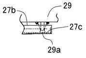
図1および図2に示すように、変電開閉設備14は、収納室18の内部に設けられ、変圧器26と架台27と連結部材28と開閉装置29と昇降器具30と遮蔽部材31と保護部材32とを有している。変圧器26は、収納室18の中央で、基礎面11aに設置されている。架台27は、基礎面11aに設置され、脚部27aと支持面27bとレール27cとを有している。支持面27bは、脚部27aにより支持されて変圧器26の上方に水平に配置されている。支持面27bは、収納室18の内壁との間に隙間を有し、タワーベース部17の接続部20と同じ高さで設けられている。図3に示すように、レール27cは、2本から成り、開閉装置29の幅より狭い間隔で平行に設けられている。レール27cは、支持面27bの端部から反対側の端部まで伸びて、支持面27bに埋め込まれている。図2に示すように、連結部材28は、支持面27bと接続部20とを連結している。 As shown in FIGS. 1 and 2, the
図1および図2に示すように、開閉装置29は、気中絶縁方式のキュービクル式開閉装置から成り、架台27の支持面27bの上で変圧器26に対し水平方向にずれて配置されている。図4(d)に示すように、開閉装置29は、そのずれた箇所で下側に垂直に伸びる送電用ケーブル1に接続されている。図3に示すように、開閉装置29は、支持面27bのレール27c上を移動可能に、4つの滑車29aを下部に有している。開閉装置29は、タワー12の内壁との間に操作点検スペース33を確保するよう支持面27bのレール27c上をスライド可能に構成されている。なお、開閉装置29は、滑車29aに限らず、支持面27bのレール27c上をスムーズにスライド可能であれば、コロその他、いかなる移動手段を有していてもよい。 As shown in FIGS. 1 and 2, the opening /
図2に示すように、昇降器具30は、梯子から成り、作業者が基礎面11aから架台27の支持面27bへ昇降可能に、基礎面11aと支持面27bとを接続して設けられている。遮蔽部材31は、金属板から成り、導電性を有している。遮蔽部材31は、両面をそれぞれ昇降器具30および変圧器26に向けて、昇降器具30と変圧器26との間に垂直に立てて設けられている。遮蔽部材31は、接地されており、基礎面11aから支持面27bまで伸びて、昇降器具30を変圧器26から隔てるよう設けられている。保護部材32は、絶縁性のベークライト板から成る。保護部材32は、遮蔽部材31の変圧器26側の面の全体を覆って貼り付けられている。なお、保護部材32は、昇降器具30と変圧器26との相対的な位置関係に応じて、作業者の安全を確保できる大きさであれば、遮蔽部材31より小さく形成されていてもよい。 As shown in FIG. 2, the lifting
次に、作用について説明する。
風力発電装置10は、タワー12の先端12aに設けられた風車13のプロペラ23の回転により発電し、その出力を収納室18の内部の変圧器26で昇圧する。昇圧した電気を開閉装置29を経て送電している。
風力発電装置10は、以下に示す方法で容易に施工することができる。Next, the operation will be described.
The
The
図4(a)に示すように、まず、基礎面11aが水平になるよう基礎11を設置する。基礎面11aの上に変圧器26を設置する。このとき、変圧器26を基礎面11aの中央位置に配置する。基礎面11aの上に、支持面27bが変圧器26の上方に配置されるよう架台27を設置する。支持面27bのレール27cに滑車29aを合わせて支持面27bの上に開閉装置29を載せ、仮固定する。このとき、開閉装置29を支持面27bの中央位置に配置する。 As shown to Fig.4 (a), the
図4(b)に示すように、収納室18に変圧器26、架台27および開閉装置29を収納するよう基礎面11aの上にタワーベース部17を被せて設置する。このとき、変圧器26、架台27および開閉装置29が収納室18の中央に位置するように被せる。なお、変圧器26は、収納室18の中央からずれて配置されていてもよい。これにより、開閉装置29とタワー12の内壁との間の距離を大きくとることができるため、タワー12を被せやすくなり、施工性が向上する。タワーベース部17の上にタワー中間部16およびタワー上部15を順に載せて設置する。あらかじめ増速機24および発電機25が収納され、ロータ軸22が取り付けられたナセル21を、タワー12の先端12aに取り付ける。ロータ軸22にプロペラ23を取り付ける。 As shown in FIG. 4B, the
図4(c)に示すように、開閉装置29の仮固定をはずし、架台27の上で開閉装置29を支持面27bの端部までレール27cに沿ってスライドさせ、タワー12の内壁に近接した位置で固定する。これにより、開閉装置29とタワー12の内壁との間の、開閉装置29をスライドして拡大した支持面27bの上の平面を、点検・作業用の操作点検スペース33として確保することができる。このため、保守性に優れている。また、小型のガス絶縁方式または固体絶縁方式の開閉装置のみならず、それらより大きい気中絶縁方式の開閉装置29を使用することができる。これにより、ガス絶縁方式または固体絶縁方式の開閉装置に比べて安価な気中絶縁方式の開閉装置29を使用して、安価に実施することができ、経済的である。 As shown in FIG. 4C, the opening /
次に、連結部材28で、支持面27bとタワーベース部17の接続部20とを連結し、固定する。これにより、支持面27bの端部に設置された開閉装置29に発生する重力による回転モーメントを、タワー12で支えることができる。このため、開閉装置29が不安定になって支持面27bから落ちるのを防ぎ、開閉装置29を安定して支持することができる。 Next, with the connecting
開閉装置29を支持面27bの上でスライドできない場合の問題点について、図5を参照して、詳細に検討する。図5は、開閉装置29をスライドできない変電開閉設備の側面図である。図5に示すように、開閉装置29を支持面27bの上でスライドできない場合、操作点検スペース33を確保するには、予め開閉装置29を支持面27bの端部に設置して、タワー12を被せたときに開閉装置29がタワー12の内部の内壁に近接した位置に配置されるようにしなければならない。この場合、開閉装置29が重力による回転モーメントにより支持面27bから落ちるのを防ぐために、支持面27bの端部と基礎面11aとの間に、開閉装置29を支持する補強材51を新たに固定する必要が生じる。また、この場合、タワー12を被せるとき、開閉装置29がタワー12の内壁に近接した位置にあるため、施工が難しく、開閉装置29にタワー12が衝突して損傷を受けないよう最新の注意を払う必要が生じる。
これに対し、風力発電装置10は、図4(c)に示すように、支持面27bの上で開閉装置29をスライドさせることができるので、このような問題を生じずに操作点検スペース33を確保することができる。このため、補強材51を設ける必要がなく、タワー12を被せる際の施工が容易である。A problem in the case where the opening /
On the other hand, since the
図4(d)に示すように、開閉装置29が支持面27bの上で、変圧器26に対し水平方向にずれて配置されているため、そのずれた箇所で、下側に伸びる送電用ケーブル1を開閉装置29の下部に接続する。これにより、収納室18の内部で、変圧器26などの障害物を避けるため送電用ケーブル1を曲げながら開閉装置29に接続する必要がなく、開閉装置29の下側から容易に送電用ケーブル1を接続することができ、施工性が向上する。 As shown in FIG. 4 (d), the
図2に示すように、昇降器具30を基礎面11aと支持面27bとを接続するよう取り付ける。これにより、作業者が昇降器具30を昇降して架台27の上の開閉装置29でメンテナンス作業を行うことができる。 As shown in FIG. 2, the
さらに、図2に示すように、遮蔽部材31および保護部材32を昇降器具30と変圧器26との間に垂直に立てて設置する。昇降器具30は絶縁性の保護部材32により変圧器26から隔てられるため、変圧器26が充電された状態であっても、作業者が変圧器26の放電により感電することなく安全に昇降器具30を昇降したり、その周辺に一時的に滞在したりすることができる。さらに、保護部材32に微細なひび割れが発生するなどして絶縁が破壊された場合でも、遮蔽部材31が導電性で接地されているため、変圧器26の放電による感電を防止することができる。このように、変圧器26による感電から二重に保護されているため、安全性が高く、作業者が安心して作業を行うことができる。 Furthermore, as shown in FIG. 2, the shielding
こうして、風力発電装置10を施工、設置することができる。なお、変圧器26、開閉装置29、タワー12、ナセル21およびプロペラ23は、大型クレーンを用いて設置される。
風力発電装置10は、タワー12の収納室18の内部に変電開閉設備14を有しているため、タワー12の外部に変電開閉設備14の設置面積を確保する必要がなく、タワー12の周辺の景観も向上する。また、タワー12の外部に変電開閉設備14を設置する場合に比べ、設置面積を小さくすることができるため、洋上設置にも適している。In this way, the
Since the
1 送電用ケーブル
10 風力発電装置
11 基礎
11a 基礎面
12 タワー
13 風車
14 変電開閉設備
15 タワー上部
16 タワー中間部
17 タワーベース部
18 収納室
19 ドア
20 接続部
21 ナセル
22 ロータ軸
23 プロペラ
23a ブレード
24 増速機
25 発電機
26 変圧器
27 架台
27a 脚部
27b 支持面
27c レール
28 連結部材
29 開閉装置
30 昇降器具
31 遮蔽部材
32 保護部材
33 操作点検スペースDESCRIPTION OF
Claims (4)
Translated fromJapanese前記タワーは収納室を有し、前記収納室の内部に変電開閉設備を有し、
前記変電開閉設備は、変圧器と、開閉装置と、前記開閉装置とタワー内壁との間に操作点検スペースを確保するよう前記変圧器の上方で前記開閉装置をスライド可能に支持する架台とを有することを、
特徴とする変電開閉設備を内蔵した風力発電装置。A wind power generator that generates power by rotating a windmill provided at the top of the tower,
The tower has a storage room, and has a transformer opening / closing facility inside the storage room,
The substation switchgear includes a transformer, a switchgear, and a mount that slidably supports the switchgear above the transformer so as to secure an operation inspection space between the switchgear and the inner wall of the tower. That
A wind power generator with a built-in transformer switchgear.
前記昇降器具を前記変圧器から隔てる接地された導電性の遮蔽部材と、
前記遮蔽部材の一方の面を覆う絶縁性の保護部材とを有することを、
特徴とする請求項1記載の変電開閉設備を内蔵した風力発電装置。There is an elevating device for an operator to elevate and lower the gantry inside the storage room,
A grounded conductive shielding member separating the lifting device from the transformer;
Having an insulating protective member that covers one surface of the shielding member;
A wind turbine generator incorporating the transformer switchgear according to claim 1.
特徴とする請求項1または2記載の変電開閉設備を内蔵した風力発電装置。The switchgear is arranged in the horizontal direction with respect to the transformer on the gantry, and is connected to a power transmission cable extending downward at the shifted position,
A wind turbine generator having a built-in transformer switchgear according to claim 1 or 2.
基礎の上に前記変圧器を設置する第1工程と、前記基礎の上に前記架台をその支持面が前記変圧器の上方に配置されるよう設置する第2工程と、前記架台の支持面の上に前記開閉装置を載せる第3工程と、前記収納室は前記タワーの底部に設けられ、前記収納室に前記変圧器、前記架台および前記開閉装置を収納するよう前記基礎の上に前記タワーを被せて設置する第4工程と、前記開閉装置とタワー内壁との間に操作点検スペースを確保するよう前記架台の上で前記開閉装置をスライドさせる第5工程とを有することを、
特徴とする変電開閉設備を内蔵した風力発電装置の施工方法。A construction method of a wind turbine generator incorporating the transformer switchgear according to claim 1,
A first step of installing the transformer on a foundation; a second step of installing the gantry on the foundation so that a support surface thereof is disposed above the transformer; and a support surface of the gantry. A third step of placing the switchgear thereon; and the storage chamber is provided at the bottom of the tower, and the tower is placed on the foundation so as to store the transformer, the gantry, and the switchgear in the storage chamber. A fourth step of covering and installing, and a fifth step of sliding the opening and closing device on the mount so as to secure an operation inspection space between the opening and closing device and the tower inner wall.
A method of constructing a wind turbine generator with a built-in transformer switchgear.
Priority Applications (1)
| Application Number | Priority Date | Filing Date | Title |
|---|---|---|---|
| JP2004183907AJP2006009596A (en) | 2004-06-22 | 2004-06-22 | Wind power generator with built-in transformation switch gear, and its construction method |
Applications Claiming Priority (1)
| Application Number | Priority Date | Filing Date | Title |
|---|---|---|---|
| JP2004183907AJP2006009596A (en) | 2004-06-22 | 2004-06-22 | Wind power generator with built-in transformation switch gear, and its construction method |
Publications (1)
| Publication Number | Publication Date |
|---|---|
| JP2006009596Atrue JP2006009596A (en) | 2006-01-12 |
Family
ID=35777121
Family Applications (1)
| Application Number | Title | Priority Date | Filing Date |
|---|---|---|---|
| JP2004183907APendingJP2006009596A (en) | 2004-06-22 | 2004-06-22 | Wind power generator with built-in transformation switch gear, and its construction method |
Country Status (1)
| Country | Link |
|---|---|
| JP (1) | JP2006009596A (en) |
Cited By (32)
| Publication number | Priority date | Publication date | Assignee | Title |
|---|---|---|---|---|
| WO2009003508A1 (en)* | 2007-06-29 | 2009-01-08 | Abb Research Ltd | Switchgear for a wind turbine and system for arranging electrical connections in a wind farm |
| CN101725151A (en)* | 2008-10-16 | 2010-06-09 | 通用电气公司 | Wind turbine tower foundation containing power and control equipment |
| JP2010275705A (en)* | 2009-05-26 | 2010-12-09 | Kajima Corp | Wind turbine generator extension and remodeling method |
| JP2011234511A (en)* | 2010-04-27 | 2011-11-17 | Toshiba Corp | Power generating/transforming equipment |
| WO2012000516A2 (en) | 2010-06-30 | 2012-01-05 | Vestas Wind Systems A/S | A method for controlling a wind turbine in a non-operational mode and a wind turbine |
| EP2426354A2 (en) | 2010-09-06 | 2012-03-07 | Hitachi Ltd. | Downwind type wind turbine |
| EP2434151A2 (en) | 2010-09-28 | 2012-03-28 | Fuji Jukogyo Kabushiki Kaisha | Wind power generator |
| JP2012067603A (en)* | 2010-09-21 | 2012-04-05 | Fuji Heavy Ind Ltd | Structure for mounting part inside wind turbine tower |
| EP2453451A2 (en) | 2010-11-12 | 2012-05-16 | Hitachi Industrial Equipment Systems Co., Ltd. | Transformer for wind power station and/or wind power generating facilities installed with transformer for wind power station |
| WO2013182205A1 (en)* | 2012-06-08 | 2013-12-12 | Vestas Wind Systems A/S | Arragnement of a switchgear in a tower of a wind turbine |
| KR20140066835A (en)* | 2012-11-22 | 2014-06-02 | 현대중공업 주식회사 | Windmill tower |
| KR101406575B1 (en) | 2012-12-27 | 2014-06-13 | 재단법인 포항산업과학연구원 | Wind turbine |
| EP2784305A1 (en)* | 2013-03-27 | 2014-10-01 | Alstom Renovables España, S.L. | A system for providing electrical power to a wind turbine component. |
| WO2015004737A1 (en)* | 2013-07-09 | 2015-01-15 | 株式会社日立産機システム | Floating offshore wind power generating device and transformer used in same |
| JP2015080402A (en)* | 2013-10-17 | 2015-04-23 | シーメンス アクチエンゲゼルシヤフトSiemens Aktiengesellschaft | Single piece electric assembly for connecting off-shore wind turbine with electric subsea cable, wind turbine, wind turbine cluster, and method for mounting such electric assembly to wind turbine tower |
| CN105840433A (en)* | 2016-05-31 | 2016-08-10 | 中国华电科工集团有限公司 | Wind turbine generator system point inspection information management system and wind turbine generator system point inspection management system |
| EP3168465A1 (en) | 2015-11-06 | 2017-05-17 | Hitachi, Ltd. | Method for constructing offshore wind turbine, offshore wind turbine, and offshore wind power generating equipment |
| JP2017145734A (en)* | 2016-02-17 | 2017-08-24 | 株式会社日立製作所 | Wind power generator |
| CN107394652A (en)* | 2017-09-19 | 2017-11-24 | 桂林君泰福电气有限公司 | A kind of embedded intelligently voltage boosting transformation device of wind-power tower |
| US9965984B2 (en) | 2012-12-05 | 2018-05-08 | Braeburn Systems, Llc | Climate control panel with non-planar display |
| US10055323B2 (en) | 2014-10-30 | 2018-08-21 | Braeburn Systems Llc | System and method for monitoring building environmental data |
| US10317867B2 (en) | 2016-02-26 | 2019-06-11 | Braeburn Systems Llc | Thermostat update and copy methods and systems |
| US10317919B2 (en) | 2016-06-15 | 2019-06-11 | Braeburn Systems Llc | Tamper resistant thermostat having hidden limit adjustment capabilities |
| US10356573B2 (en) | 2014-10-22 | 2019-07-16 | Braeburn Systems Llc | Thermostat synchronization via remote input device |
| US10423142B2 (en) | 2015-02-10 | 2019-09-24 | Braeburn Systems Llc | Thermostat configuration duplication system |
| US10430056B2 (en) | 2014-10-30 | 2019-10-01 | Braeburn Systems Llc | Quick edit system for programming a thermostat |
| US10761704B2 (en) | 2014-06-16 | 2020-09-01 | Braeburn Systems Llc | Graphical highlight for programming a control |
| US10802513B1 (en) | 2019-05-09 | 2020-10-13 | Braeburn Systems Llc | Comfort control system with hierarchical switching mechanisms |
| CN111779619A (en)* | 2020-07-30 | 2020-10-16 | 上海勘测设计研究院有限公司 | A tidal current power generation project integrating a generator set and a booster station |
| US10921008B1 (en) | 2018-06-11 | 2021-02-16 | Braeburn Systems Llc | Indoor comfort control system and method with multi-party access |
| US11269364B2 (en) | 2016-09-19 | 2022-03-08 | Braeburn Systems Llc | Control management system having perpetual calendar with exceptions |
| US11925260B1 (en) | 2021-10-19 | 2024-03-12 | Braeburn Systems Llc | Thermostat housing assembly and methods |
- 2004
- 2004-06-22JPJP2004183907Apatent/JP2006009596A/enactivePending
Cited By (42)
| Publication number | Priority date | Publication date | Assignee | Title |
|---|---|---|---|---|
| WO2009003508A1 (en)* | 2007-06-29 | 2009-01-08 | Abb Research Ltd | Switchgear for a wind turbine and system for arranging electrical connections in a wind farm |
| CN101725151A (en)* | 2008-10-16 | 2010-06-09 | 通用电气公司 | Wind turbine tower foundation containing power and control equipment |
| JP2010275705A (en)* | 2009-05-26 | 2010-12-09 | Kajima Corp | Wind turbine generator extension and remodeling method |
| JP2011234511A (en)* | 2010-04-27 | 2011-11-17 | Toshiba Corp | Power generating/transforming equipment |
| WO2012000516A2 (en) | 2010-06-30 | 2012-01-05 | Vestas Wind Systems A/S | A method for controlling a wind turbine in a non-operational mode and a wind turbine |
| US8716878B2 (en) | 2010-09-06 | 2014-05-06 | Hitachi, Ltd. | Downwind type wind turbine having transformer therein and operating method thereof |
| EP2426354A2 (en) | 2010-09-06 | 2012-03-07 | Hitachi Ltd. | Downwind type wind turbine |
| JP2012067603A (en)* | 2010-09-21 | 2012-04-05 | Fuji Heavy Ind Ltd | Structure for mounting part inside wind turbine tower |
| EP2434151A2 (en) | 2010-09-28 | 2012-03-28 | Fuji Jukogyo Kabushiki Kaisha | Wind power generator |
| EP2453451A2 (en) | 2010-11-12 | 2012-05-16 | Hitachi Industrial Equipment Systems Co., Ltd. | Transformer for wind power station and/or wind power generating facilities installed with transformer for wind power station |
| WO2013182205A1 (en)* | 2012-06-08 | 2013-12-12 | Vestas Wind Systems A/S | Arragnement of a switchgear in a tower of a wind turbine |
| US9638172B2 (en) | 2012-06-08 | 2017-05-02 | Vestas Wind Systems A/S | Arrangement of a switchgear of a wind turbine |
| EP2859231B1 (en) | 2012-06-08 | 2017-08-09 | Vestas Wind Systems A/S | Arrangement of a switchgear in a tower of a wind turbine |
| KR101997265B1 (en)* | 2012-11-22 | 2019-07-08 | 두산중공업 주식회사 | Windmill tower and windmill having the same |
| KR20140066835A (en)* | 2012-11-22 | 2014-06-02 | 현대중공업 주식회사 | Windmill tower |
| US9965984B2 (en) | 2012-12-05 | 2018-05-08 | Braeburn Systems, Llc | Climate control panel with non-planar display |
| KR101406575B1 (en) | 2012-12-27 | 2014-06-13 | 재단법인 포항산업과학연구원 | Wind turbine |
| US9124143B2 (en) | 2013-03-27 | 2015-09-01 | Alstom Renewable Technologies | System for providing electrical power to a wind turbine component |
| EP2784305A1 (en)* | 2013-03-27 | 2014-10-01 | Alstom Renovables España, S.L. | A system for providing electrical power to a wind turbine component. |
| JPWO2015004737A1 (en)* | 2013-07-09 | 2017-02-23 | 株式会社日立産機システム | Floating offshore wind turbine generator and transformer used therefor |
| WO2015004737A1 (en)* | 2013-07-09 | 2015-01-15 | 株式会社日立産機システム | Floating offshore wind power generating device and transformer used in same |
| JP2015080402A (en)* | 2013-10-17 | 2015-04-23 | シーメンス アクチエンゲゼルシヤフトSiemens Aktiengesellschaft | Single piece electric assembly for connecting off-shore wind turbine with electric subsea cable, wind turbine, wind turbine cluster, and method for mounting such electric assembly to wind turbine tower |
| US10761704B2 (en) | 2014-06-16 | 2020-09-01 | Braeburn Systems Llc | Graphical highlight for programming a control |
| US10931470B1 (en) | 2014-10-22 | 2021-02-23 | Braeburn Systems Llc | Thermostat synchronization via remote input device |
| US10356573B2 (en) | 2014-10-22 | 2019-07-16 | Braeburn Systems Llc | Thermostat synchronization via remote input device |
| US10430056B2 (en) | 2014-10-30 | 2019-10-01 | Braeburn Systems Llc | Quick edit system for programming a thermostat |
| US10055323B2 (en) | 2014-10-30 | 2018-08-21 | Braeburn Systems Llc | System and method for monitoring building environmental data |
| US10423142B2 (en) | 2015-02-10 | 2019-09-24 | Braeburn Systems Llc | Thermostat configuration duplication system |
| JP2017089447A (en)* | 2015-11-06 | 2017-05-25 | 株式会社日立製作所 | Offshore wind turbine construction method, offshore wind turbine and offshore wind power generation equipment |
| US9982658B2 (en) | 2015-11-06 | 2018-05-29 | Hitachi, Ltd. | Offshore wind turbine, method for constructing offshore wind turbine, and offshore wind power generator |
| EP3168465A1 (en) | 2015-11-06 | 2017-05-17 | Hitachi, Ltd. | Method for constructing offshore wind turbine, offshore wind turbine, and offshore wind power generating equipment |
| JP2017145734A (en)* | 2016-02-17 | 2017-08-24 | 株式会社日立製作所 | Wind power generator |
| US10317867B2 (en) | 2016-02-26 | 2019-06-11 | Braeburn Systems Llc | Thermostat update and copy methods and systems |
| CN105840433A (en)* | 2016-05-31 | 2016-08-10 | 中国华电科工集团有限公司 | Wind turbine generator system point inspection information management system and wind turbine generator system point inspection management system |
| CN105840433B (en)* | 2016-05-31 | 2020-08-28 | 中国华电科工集团有限公司 | Wind turbine generator system point inspection information management system and wind turbine generator system point inspection management system |
| US10317919B2 (en) | 2016-06-15 | 2019-06-11 | Braeburn Systems Llc | Tamper resistant thermostat having hidden limit adjustment capabilities |
| US11269364B2 (en) | 2016-09-19 | 2022-03-08 | Braeburn Systems Llc | Control management system having perpetual calendar with exceptions |
| CN107394652A (en)* | 2017-09-19 | 2017-11-24 | 桂林君泰福电气有限公司 | A kind of embedded intelligently voltage boosting transformation device of wind-power tower |
| US10921008B1 (en) | 2018-06-11 | 2021-02-16 | Braeburn Systems Llc | Indoor comfort control system and method with multi-party access |
| US10802513B1 (en) | 2019-05-09 | 2020-10-13 | Braeburn Systems Llc | Comfort control system with hierarchical switching mechanisms |
| CN111779619A (en)* | 2020-07-30 | 2020-10-16 | 上海勘测设计研究院有限公司 | A tidal current power generation project integrating a generator set and a booster station |
| US11925260B1 (en) | 2021-10-19 | 2024-03-12 | Braeburn Systems Llc | Thermostat housing assembly and methods |
Similar Documents
| Publication | Publication Date | Title |
|---|---|---|
| JP2006009596A (en) | Wind power generator with built-in transformation switch gear, and its construction method | |
| EP2863053B1 (en) | Single piece electric assembly for connecting an off-shore wind turbine with an electric subsea cable and mounting method therefor | |
| USRE41073E1 (en) | Wind power plant with a transformer fixed to the tower | |
| EP2859231B1 (en) | Arrangement of a switchgear in a tower of a wind turbine | |
| EP2565445B1 (en) | Transformer chamber for a wind turbine, wind turbine structure component, wind turbine, and method for assembling a wind turbine | |
| EP3891387B1 (en) | Wind turbine tower transition piece | |
| JP5438428B2 (en) | Wind power generation system with bus bar | |
| EP2143937A2 (en) | Cable bridge for a wind turbine tower | |
| CN1553995A (en) | Wind turbine power plant built on a foundation | |
| CN110537020B (en) | Wind power system with low electromagnetic interference | |
| TW201716691A (en) | Offshore Wind Turbine, Method for Constructing Offshore Wind Turbine, and Offshore Wind Power Generator | |
| JP2005506488A (en) | Wind energy plant with current bus | |
| JP2022159016A (en) | Electrical filters for wind turbines | |
| JP2020502425A (en) | Wind turbine with cable support structure | |
| CN107850038B (en) | Cabling for wind turbine system with multiple rotors | |
| EP4234925A1 (en) | Wind turbine and method for manufacturing a wind turbine | |
| US20230184228A1 (en) | Wind turbine with cable arrangement | |
| KR101549502B1 (en) | Apparatus for equipping a cable of an aerogenerator |