JP2006006583A - Pressure cooker - Google Patents
Pressure cookerDownload PDFInfo
- Publication number
- JP2006006583A JP2006006583AJP2004187184AJP2004187184AJP2006006583AJP 2006006583 AJP2006006583 AJP 2006006583AJP 2004187184 AJP2004187184 AJP 2004187184AJP 2004187184 AJP2004187184 AJP 2004187184AJP 2006006583 AJP2006006583 AJP 2006006583A
- Authority
- JP
- Japan
- Prior art keywords
- lid
- handle
- cooking container
- pressure cooking
- pressure
- Prior art date
- Legal status (The legal status is an assumption and is not a legal conclusion. Google has not performed a legal analysis and makes no representation as to the accuracy of the status listed.)
- Withdrawn
Links
- 238000004140cleaningMethods0.000claimsabstractdescription70
- 230000001105regulatory effectEffects0.000claimsabstractdescription23
- 238000010411cookingMethods0.000claimsdescription44
- 239000002184metalSubstances0.000claimsdescription14
- 238000012856packingMethods0.000claimsdescription5
- 239000007788liquidSubstances0.000description5
- 230000004308accommodationEffects0.000description2
- 230000007797corrosionEffects0.000description2
- 238000005260corrosionMethods0.000description2
- 230000002093peripheral effectEffects0.000description2
- 239000004071sootSubstances0.000description2
- 240000007594Oryza sativaSpecies0.000description1
- 235000007164Oryza sativaNutrition0.000description1
- 238000009835boilingMethods0.000description1
- 238000001035dryingMethods0.000description1
- 238000003780insertionMethods0.000description1
- 230000037431insertionEffects0.000description1
- 230000003014reinforcing effectEffects0.000description1
- 235000009566riceNutrition0.000description1
- 230000000630rising effectEffects0.000description1
- 229910001220stainless steelInorganic materials0.000description1
- 239000010935stainless steelSubstances0.000description1
- 238000005406washingMethods0.000description1
Images


Landscapes
- Cookers (AREA)
Abstract
Description
Translated fromJapaneseこの発明は、例えば鍋や炊飯釜等の圧力調理容器に関するものである。 The present invention relates to a pressure cooking container such as a pot or a rice cooker.
従来、この種の圧力調理容器として、容器本体を閉塞する蓋体の中央部に立設するロッドと、その両端が上記容器本体の対向する部位に装着された受け金具に係合可能な断面略逆U字状のアームと、上記ロッドに設けられたねじ部に螺合するスリーブに係合し、かつ、スリーブと共働してアームを支持するハンドルとを具備し、ハンドルの回転により上記アームを昇降させて、アームの端部を受け金具に係合した状態で使用する圧力調理容器が知られている(例えば、特許文献1参照)。 Conventionally, as a pressure cooking container of this type, a cross-section that can be engaged with a rod standing at the center of a lid that closes the container body and a receiving metal fitting that has both ends attached to the opposing parts of the container body. The arm includes an inverted U-shaped arm and a handle that engages with a sleeve that is screwed to a threaded portion provided on the rod and supports the arm in cooperation with the sleeve. There is known a pressure cooking container that is used in a state where the end of the arm is engaged with a metal fitting by raising and lowering the arm (see, for example, Patent Document 1).
また、この圧力調理容器には、調理時の容器内の圧力を調整する重り付きの調圧弁と、容器内が異常高圧時に作動する安全弁とが設けられている。
ところで、この種の圧力調理容器を安全に使用するためには、調圧弁や安全弁のノズル部を掃除する必要がある。この場合、調圧弁や安全弁のノズルの汚れや詰まりを取り除くためにクリーニングピンが一般に便利とされている。 By the way, in order to use this kind of pressure cooking container safely, it is necessary to clean the nozzle part of a pressure regulation valve or a safety valve. In this case, a cleaning pin is generally convenient for removing dirt and clogging of the nozzles of the pressure regulating valve and the safety valve.
しかしながら、クリーニングピンは小さい部材であるため、不使用時の保管場所に注意しないと紛失することがあり、調圧弁や安全弁のノズル部を掃除することができなくなる虞がある。 However, since the cleaning pin is a small member, it may be lost if care is not taken in the storage place when not in use, and the nozzle part of the pressure regulating valve or safety valve may not be cleaned.
この発明は、上記事情に鑑みてなされたもので、圧力調理容器自体にクリーニングピンの収納部を設けてクリーニングピンの紛失を防止すると共に、調圧弁や安全弁のノズル部の掃除を容易に行えるようして、圧力調理容器を安全に使用できるようにすることを課題とする。 The present invention has been made in view of the above circumstances, and the pressure cooking container itself is provided with a cleaning pin housing part to prevent the cleaning pin from being lost, and the nozzle part of the pressure regulating valve and the safety valve can be easily cleaned. Then, it makes it a subject to make it possible to use a pressure cooking container safely.
上記目的を達成するために、この発明の圧力調理容器は、容器本体と、この容器本体を閉塞する蓋体と、この蓋体に設けられ、容器内の圧力を調整する調圧弁及び、容器内が所定圧以上時に作動する安全弁と、蓋体の中央部に立設するロッドと、その両端が上記容器本体の対向する部位に装着された受け金具に係合可能なアームと、上記ロッドに設けられたねじ部に螺合するスリーブに係合し、かつ、スリーブと共働してアームを昇降可能に支持するハンドルとを具備する圧力調理容器において、 上記ハンドルは、収納凹部を有するハンドル本体と、このハンドル本体の収納凹部の開口部を開閉可能に閉塞する蓋とを具備し、上記収納凹部内に、上記調圧弁及び安全弁を掃除するためのクリーニングピンを収納可能に形成してなる、ことを特徴とする(請求項1)。 In order to achieve the above object, a pressure cooking container according to the present invention includes a container body, a lid for closing the container body, a pressure regulating valve for adjusting the pressure in the container, Provided on the rod, a safety valve that operates when the pressure exceeds a predetermined pressure, a rod that stands in the center of the lid, an arm that can engage both ends of the receiving bracket that is attached to the opposite part of the container body, and A pressure cooking container that includes a handle that engages with a sleeve that is screwed into the threaded portion and that supports the arm so as to be able to move up and down in cooperation with the sleeve. A lid for closing the opening of the storage recess of the handle body so as to be openable and closable, and a cleaning pin for cleaning the pressure regulating valve and the safety valve is formed in the storage recess so as to be retractable. The The characters (claim 1).
この発明において、上記蓋とハンドル本体とをヒンジを介して開閉可能に連結することができる(請求項2)。この場合、上記ヒンジを、蓋又はハンドル本体のいずれか一方に突設されるヒンジピンと、他方に設けられてヒンジピンを回動自在に支承するヒンジ受けとで構成し、上記ヒンジ受けに、上記蓋が過度に開放された際に上記ヒンジピンの支承を解除して蓋を取り外す切欠きを設けておく方が好ましい(請求項3)。 In the present invention, the lid and the handle body can be connected via a hinge so as to be opened and closed (claim 2). In this case, the hinge is composed of a hinge pin protruding from one of the lid and the handle body, and a hinge receiver provided on the other side to rotatably support the hinge pin. It is preferable to provide a notch for releasing the cover of the hinge pin and removing the lid when the cover is excessively opened.
また、上記蓋と収納凹部の開口部とを、パッキンを介して気水密に、かつ、着脱可能に嵌合すると共に、蓋とハンドル本体とを可撓性を有する索条を介して連結するようにしてもよい(請求項4)。 Further, the lid and the opening of the storage recess are fitted in a gas-tight manner and detachably through the packing, and the lid and the handle main body are connected through a flexible cable. (Claim 4).
また、上記蓋の下部に、収納凹部内に挿入可能な支持片を設け、この支持片に載置した状態でクリーニングピンを収納凹部内に収納可能に形成してもよい(請求項5)。 Further, a support piece that can be inserted into the storage recess is provided at the lower part of the lid, and the cleaning pin may be stored in the storage recess while being placed on the support piece.
また、上記蓋とハンドル本体とを着脱可能に螺合すると共に、蓋とハンドル本体とを可撓性を有する索条を介して連結してもよい(請求項6)。 In addition, the lid and the handle main body may be detachably screwed together, and the lid and the handle main body may be coupled via a flexible cable.
また、上記ハンドル本体における収納凹部の開口部に、一端が開口する一対の凹条又は凸条を形成し、上記蓋の両側辺に、上記凹条又は凸条に摺動可能に嵌合する係合凸条又は係合凹条を形成して、蓋を開閉摺動可能に形成してもよい(請求項7)。 In addition, a pair of recesses or ridges that open at one end is formed at the opening of the housing recess in the handle body, and the slidably fitted into the recesses or ridges on both sides of the lid. A joint ridge or engagement groove may be formed, and the lid may be formed to be openable and slidable (claim 7).
更には、上記蓋とハンドル本体とを枢支ピンを介して連結して、蓋を収納凹部の開口部の開口面に対して平行に開閉回転可能に形成してもよい(請求項8)。 Further, the lid and the handle main body may be connected via a pivot pin so that the lid can be opened and closed in parallel with the opening surface of the opening of the storage recess (claim 8).
また、上記ハンドル本体の収納凹部の底部に、1又は複数の水抜き孔を設ける方が好ましい(請求項9)。 Further, it is preferable to provide one or a plurality of drain holes at the bottom of the housing recess of the handle body.
また、上記ハンドル本体の収納凹部に、クリーニングピンを着脱可能に保持する保持部を設ける方が好ましい(請求項10)。 Further, it is preferable to provide a holding portion for detachably holding the cleaning pin in the storage recess of the handle body.
請求項11記載の発明は、 容器本体と、この容器本体を閉塞する蓋体と、この蓋体に設けられ、容器内の圧力を調整する調圧弁及び、容器内が所定圧以上時に作動する安全弁と、蓋体の中央部に立設するロッドと、その両端が上記容器本体の対向する部位に装着された受け金具に係合可能なアームと、上記ロッドに設けられたねじ部に螺合するスリーブに係合し、かつ、スリーブと共働してアームを昇降可能に支持するハンドルとを具備する圧力調理容器において、 上記ハンドルは、収納凹部を有するハンドル本体と、このハンドル本体の収納凹部内に挿脱可能に挿入される内ケースとを具備し、 上記内ケースを、第2の収納凹部を有する内ケース本体と、この内ケース本体の第2の収納凹部の開口部を開閉する内蓋とで構成すると共に、第2の収納凹部内に、上記調圧弁及び安全弁を掃除するためのクリーニングピンを収納可能に形成してなる、ことを特徴とする。この発明において、上記内ケースの第2の収納凹部に、クリーニングピンを着脱可能に保持する保持部を設ける方が好ましい(請求項12)。 The invention according to
(1)請求項1,2,4〜8記載の発明によれば、圧力調理容器の蓋体に装着されるハンドルに設けられた収納凹部内にクリーニングピンを収納することができるので、クリーニングピンの紛失を防止することができる。したがって、クリーニングピンを用いて調圧弁及び安全弁のノズルの掃除を容易に行うことができ、調圧弁及び安全弁の機能を維持した状態にして圧力調理容器の安全面を確保することができる。 (1) According to the first, second, fourth and eighth aspects of the invention, the cleaning pin can be stored in the storage recess provided in the handle attached to the lid of the pressure cooking container. Can be lost. Therefore, the nozzle of the pressure regulating valve and the safety valve can be easily cleaned using the cleaning pin, and the safety aspect of the pressure cooking container can be ensured while maintaining the functions of the pressure regulating valve and the safety valve.
(2)請求項3記載の発明によれば、蓋とハンドル本体とを開閉可能に連結するヒンジを、蓋又はハンドル本体のいずれか一方に突設されるヒンジピンと、他方に設けられてヒンジピンを回動自在に支承するヒンジ受けとで構成し、ヒンジ受けに、蓋が過度に開放された際にヒンジピンの支承を解除して蓋を取り外す切欠きを設けることにより、過度な力で蓋が開放されたときに、蓋やヒンジ部が破損するのを防止することができる。 (2) According to the invention described in
(3)請求項9記載の発明によれば、ハンドル本体の収納凹部の底部に、1又は複数の水抜き孔を設けることにより、収納凹部内に侵入した液を水抜き孔から外部に排出することができると共に、ロッドから取り外されたハンドルを洗浄する際に洗浄液を水抜き孔から排出することができる。したがって、収納凹部内に侵入した液の残留による腐食や黴等の発生を防止することができると共に、洗浄後の水切りを良好にすることができる。 (3) According to the ninth aspect of the invention, by providing one or a plurality of drain holes at the bottom of the storage recess of the handle body, the liquid that has entered the storage recess is discharged from the drain hole to the outside. In addition, the cleaning liquid can be discharged from the drain hole when the handle removed from the rod is cleaned. Therefore, it is possible to prevent the occurrence of corrosion and soot due to the remaining liquid that has entered the storage recess, and to improve drainage after washing.
(4)請求項10,12記載の発明によれば、収納凹部に、クリーニングピンを着脱可能に保持する保持部を設けることにより、ハンドルの回転によりクリーニングピンが収納凹部内で移動するのを防止することができる。また、特に、複数のクリーニングピンの収納を容易にすることができる。 (4) According to the tenth and twelfth aspects of the present invention, the cleaning recess is prevented from moving in the storage recess by the rotation of the handle by providing the storage recess with the holding portion that detachably holds the cleaning pin. can do. In particular, the plurality of cleaning pins can be easily accommodated.
(5)請求項11記載の発明によれば、ハンドル本体の収納凹部内に挿脱可能に挿入される内ケースを、第2の収納凹部を有する内ケース本体と、この内ケース本体の第2の収納凹部の開口部を開閉する内蓋とで構成すると共に、第2の収納凹部内に、クリーニングピンを収納可能に形成することにより、内ケースをハンドルから取り出して、クリーニングピンを使用することができるので、上記(1)に加えて更に、クリーニングピンの使用を容易にすることができる。また、内ケースをハンドルから取り出して保管することができるので、圧力調理容器以外の場所においてもクリーニングピンを紛失させることなく保管することができる。 (5) According to the invention described in
以下に、この発明を実施するための最良の実施形態について添付図面に基づいて説明する。ここでは、圧力調理容器を圧力鍋に適用した場合について説明する。 The best mode for carrying out the present invention will be described below with reference to the accompanying drawings. Here, the case where a pressure cooking container is applied to a pressure cooker is demonstrated.
<第1実施形態>
図1は、この発明に係る圧力調理容器である圧力鍋の第1実施形態を示す断面図、図2は、図1のI−I線に沿う断面図である。<First Embodiment>
FIG. 1 is a cross-sectional view showing a first embodiment of a pressure cooker which is a pressure cooking container according to the present invention, and FIG. 2 is a cross-sectional view taken along the line II of FIG.
上記圧力鍋は、容器本体である鍋本体1と、鍋本体1の開口部2をパッキン3を介して閉塞する蓋体4と、蓋体4の中央部に立設するロッド5と、その両端が鍋本体1の対向する部位に装着された一対の受け金具20に係合可能なアーム10と、ロッド5に設けられた雄ねじ部5aに螺合するスリーブ6に係合し、かつ、スリーブ6と共働してアーム10を昇降可能に支持するハンドル30とを具備し、ハンドル30の回転によりアーム10が昇降されて、受け金具20に係合されるように構成されている。 The pressure cooker includes a pot body 1 that is a container body, a lid 4 that closes an opening 2 of the pot body 1 via a
また、蓋体4には、調理時の容器内の圧力を調整する重り付きの調圧弁7と、容器内が異常高圧時に作動する安全弁8とが設けられている。また、鍋本体1の対向する両壁には把手9が固着されている。 The lid 4 is provided with a pressure regulating valve 7 with a weight for adjusting the pressure in the container during cooking, and a safety valve 8 that operates when the inside of the container is abnormally high in pressure. A
上記アーム10は、図1及び図2に示すように、断面略逆U字状のステンレス製のチャンネル部材にて形成されており、両端部11の上面が平坦状に形成され、中央部12が上方に向かって緩やかに屈曲するアーチ状に形成されている。この場合、アーム10の端部11の平坦部には、アーム10の長手方向と直交する方向に延びる長孔状の係止孔13が穿設されており、平坦状の上面に連なる両側部14が凸円弧状に形成されている。また、アーム10の中央部12には、角孔15が穿設されている。 As shown in FIGS. 1 and 2, the
上記ロッド5は、蓋体4及び蓋体4の中央部に固定された補強板4aに設けられた貫通孔4bを、上方から貫通して下方に突出するねじ部にナット51を螺合して立設固定され、下部の大径部52に雄ねじ部5aが設けられた段付きシャフトにて形成されている。 The rod 5 is formed by screwing a
上記のように形成されるロッド5の大径部52に設けられた雄ねじ部5aには、アーム10を支持する段付きスリーブ6が螺合されており、上部の小径部53には、ハンドル30の回転によるアーム10の上限位置以上の上昇を防止するクラッチ機構40を介してハンドル30が着脱可能に嵌合され、ロッド5の上端部に設けられた雌ねじ部に螺着する止めねじ55によってハンドル30が固定されるようになっている。 A stepped sleeve 6 that supports the
この場合、クラッチ機構40は、段付きスリーブ6の上端部に配設されるコイルスプリング41と、ロッド5に摺動可能に嵌挿されてコイルスプリング41の上端部に当接し、かつ、上面に放射状の凹凸歯(図示せず)を有する円形状の下部ラチェット板42と、ロッド5を貫通しコイルスプリング41を圧縮した状態で下部ラチェット板42に係合する止めピン(図示せず)と、下面に下部ラチェット板42の凹凸歯に噛合する放射状の凹凸歯(図示せず)を有し、かつ、止めピンを摺動自在に嵌合する溝(図示せず)を有してロッド5に回転可能に係合される四角形状の上部ラチェット板43と、ロッド5に嵌合されて上部ラチェット板44の上方への移動を規制する止め輪(図示せず)とで構成されている。 In this case, the clutch mechanism 40 includes a
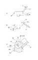
上記ハンドル30は、クラッチ機構40の上部ラチェット板43に係合する四角穴31を有する筒状のボス部32と、ボス部32の上部から外方に延在する略矩形状の摘み部33とを一体に形成したプラスチック製部材にて形成されるハンドル本体34と、ヒンジ35を介してハンドル本体34の摘み部33に形成された収納凹部36の開口部36aを開閉するプラスチック製の蓋37とで主に構成されている。 The
この場合、収納凹部36は、中央部にボス部32から上方に膨隆する筒状部36bを残して凹状に形成されており、この収納凹部36内に、上記調圧弁7及び安全弁8のノズルを掃除するための2種類のクリーニングピン70A,70Bを着脱可能に保持する保持部38が設けられている(図3参照)。このように、収納凹部36内に、クリーニングピン70A,70Bを着脱可能に保持する保持部38を設けることにより、収納凹部36内へのクリーニングピン70A,70Bの収まりを良好にすることができると共に、クリーニングピン70A,70Bの取り出しを容易にすることができる。また、収納凹部36内にクリーニングピン70A,70Bを収納した状態でハンドル30を回転しても、クリーニングピン70A,70Bは保持部38によって保持されて移動することがないので、ハンドル30の回転操作時にクリーニングピン70A,70Bの移動によるガタツキ音や振動等の違和感がない。 In this case, the
なお、一方のクリーニングピン70Aは、調圧弁7及び安全弁8のノズル孔内に挿入可能なピン70aの先端部にロール状のブラシ70bを設けた形状に形成されており、他方のクリーニングピン70Bは、調圧弁7及び安全弁8のノズル孔に連通するスリット(図示せず)内に挿入されるピン70cの先端部の一側に帯状のブラシ70dを設けた形状に形成されている。 One
また、筒状部36bの底部には、上記止めねじ55が貫挿する透孔36cが設けられており、筒状部36bの底部に止めねじ55の頭部が露出している。この止めねじ55の頭部は、筒状部36bの上端開口部に被着されるキャップ部材36dによって目隠しされている。 A through
また、上記ヒンジ35は、図3及び図4に示すように、蓋37の一側辺に間隔をおいて設けられた一対のブラケット37aから対向する側に突設されるヒンジピン37bと、ハンドル本体34に設けられてヒンジピン37bを回動自在に支承するヒンジ受け34aとで構成されている。この場合、ヒンジ受け34aに、蓋37が過度に開放された際にヒンジピン37bの支承を解除して蓋37を取り外す切欠き39が設けられている(図4参照)。このように、ヒンジ受け34aに、ヒンジピン37bの支承を解除して蓋37を取り外す切欠き39を設けることにより、蓋37を開放して、収納凹部36内からクリーニングピン70A,70Bを取り出す際に、過度な力F(図4参照)が蓋37に加わった際に、ヒンジピン37bが切欠き39から抜け出して、蓋37及びヒンジ部が破壊されるのを防止することができる。 Further, as shown in FIGS. 3 and 4, the
なお、上記説明では、蓋37のブラケット37aにヒンジピン37bを突設し、ハンドル本体34のヒンジ受け34aに切欠き39を設ける場合について説明したが、逆にしてもよい。すなわち、ヒンジ受け34aにヒンジピン37bを突設し、蓋37のブラケット37aに切欠き39を設けるようにしてもよい。 In the above description, the case where the
また、図3に示すように、ハンドル本体34に設けられた収納凹部36の底部には、1又は複数(図面では、2個の場合を示す)の水抜き孔60が設けられている。このように、収納凹部36の底部に水抜き孔60を設けることにより、収納凹部36内に侵入する液を水抜き孔60を介して外部に排出することができるので、収納凹部36内に液が残留して腐食や黴等を生じるのを防止することができる。また、ロッド5からハンドル30を取り外して洗浄するときには、洗浄液を水抜き孔60から外部に排出することができるので、水切りを良好にすることができ、洗浄後のハンドル30の乾燥時間を短縮することができる。 As shown in FIG. 3, one or a plurality of drain holes 60 (two are shown in the drawing) are provided at the bottom of the
上記受け金具20は、図1及び図2に示すように、鍋本体1の側壁部に固定ねじ21をもって固定される取付片22と、この取付片22の上端から外方に延在する傾斜片23と、傾斜片23の上端から垂直状に延在する垂直片24と、垂直片24の上端から内方側に向かって延在する緩やかなアーチ状に形成されるアーム係止片25と、アーム係止片25の先端から垂下する係止舌片26とを具備している。なお、固定ねじ21によって受け金具20と把手9とが固定されている。 As shown in FIGS. 1 and 2, the receiving
また、受け金具20のアーム係止片25における蓋体4の中心に対して対角線側に、それぞれアーム10の移動を規制する側片27が延在されている。この場合、側片27は、受け金具20も正面視において右側に形成されている。 Further,
上記のように構成される圧力鍋において、鍋本体1の開口部2に蓋体4を被せ、アーム10の端部11を受け金具20の部位にセットした状態で、ハンドル30を回転してアーム10を上昇させると、アーム10の端部11が受け金具20のアーム係止片25に係合すると共に、係止孔13内に係止舌片26が遊嵌して係合可能な状態となる。この際、アーム10の端部11を受け金具20に対して斜めにセットしても、ハンドル30の回転により、アーム10の側部が上昇するに伴って受け金具20の側片27によって移動が規制されると共に、凹円弧状案内面28に沿ってアーム係止片25の中心側に移動し、かつ、基端部及び先端部が円弧状に形成された係止舌片26がスムーズに係止孔13側に案内されて係止孔13内に遊嵌して、係合可能な状態となる。 In the pressure cooker configured as described above, the
これにより、使用中の沸騰圧力によってアーム10が変位しても係止孔13と係止舌片26とが噛み合った状態に係合するので、蓋体4が外れ飛ぶのを防止することができる。 Thereby, even if the
上記のように構成される圧力鍋において、調圧弁7や安全弁8のノズルの汚れや詰まりを清掃する場合には、ハンドル30に設けられた蓋37を開放して、収納凹部36内に収納されているクリーニングピン70A,70Bを取り出し、取り出されたクリーニングピン70A,70Bによって調圧弁7や安全弁8のノズルを掃除して汚れ,詰まりを除去することができる。したがって、圧力鍋を長期に渡って安全に使用することができる。 In the pressure cooker configured as described above, when the dirt and clogging of the nozzles of the pressure regulating valve 7 and the safety valve 8 are to be cleaned, the
なお、掃除を行った後、再びクリーニングピン70A,70Bを収納凹部36内に収納、具体的には、クリーニングピン70A,70Bを保持部38によって保持した状態で収納して、蓋37を閉じた状態で、圧力鍋を使用することができる。 After cleaning, the cleaning pins 70A and 70B are again stored in the storage recesses 36. Specifically, the cleaning pins 70A and 70B are stored while being held by the holding
<第2実施形態>
図5は、この発明におけるハンドルの第2実施形態を示す分解断面図である。Second Embodiment
FIG. 5 is an exploded sectional view showing a second embodiment of the handle according to the present invention.
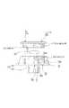
第2実施形態のハンドル30Aは、第1実施形態と同様に収納凹部36を有するハンドル本体34における開口部36aに、蓋37Aを気水密かつ着脱可能に嵌合した場合である。 The
この場合、蓋37Aの下部には、収納凹部36の開口部36a内に嵌挿される環状脚部37cが設けられており、この環状脚部37cの外周に設けられた周溝37dにパッキンとしてのOリング37eが嵌装されている。このように、蓋37Aの環状脚部37cにOリング37eを取り付けた状態で、蓋37Aを収納凹部36の開口部36aに嵌合することにより、蓋37Aを気水密に、かつ、着脱可能に嵌合することができる。 In this case, an annular leg 37c that is fitted into the
なお、この場合、蓋37Aの環状脚部37cの内周面の一側に突設された取付片37fと、収納凹部36の底部に一側に突設された取付片36eにそれぞれ設けられた取付孔37gに取り付けられる可撓性を有する索条例えばチェーン80を介して蓋37Aとハンドル本体34とが連結されている。このように、蓋37Aとハンドル本体34とをチェーン80を介して連結することにより、クリーニングピン70A,70Bを収納凹部36から取り出すとき、あるいは、クリーニングピン70A,70Bを収納凹部36に収納するときに、ハンドル本体34から蓋37Aを取り外した際に、蓋37Aが紛失するのを防止することができる。 In this case, the mounting
なお、第2実施形態においては、収納凹部36に保持部38が設けられていないが、第1実施形態と同様に、保持部38を設ける方が好ましい。 In the second embodiment, the holding
なお、第2実施形態において、その他の部分は第1実施形態と同じであるので、同一部分には同一符号を付して、説明は省略する。 In the second embodiment, the other parts are the same as those in the first embodiment, so the same parts are denoted by the same reference numerals and description thereof is omitted.
<第3実施形態>
図6は、この発明におけるハンドルの第3実施形態を示す分解断面図である。<Third Embodiment>
FIG. 6 is an exploded cross-sectional view showing a third embodiment of the handle according to the present invention.
第3実施形態のハンドル30Bは、蓋37Bの下部に、収納凹部36内に挿入可能な筒部90aと、この筒部90aの下端から外向きに突出する外向きフランジ部90bとからなる支持片90を設け、この支持片90に載置した状態でクリーニングピン70A,70Bを収納凹部36内に収納可能に形成した場合である。 The
このように、蓋37Bの下部に設けた支持片90によってクリーニングピン70A,70Bを載置した状態で収納し、支持片90を収納凹部36内に挿入可能に形成することにより、蓋37Bをハンドル本体34の収納凹部36から引き上げてクリーニングピン70A,70Bを取り出すことができる。また、使用後には、クリーニングピン70A,70Bを支持片90の外向きフランジ部90b上に載置した状態で支持片90を収納凹部36内に挿入してクリーニングピン70A,70Bを収納凹部36内に収納することができる。 As described above, the cleaning pins 70A and 70B are accommodated by the support piece 90 provided in the lower part of the
なお、第3実施形態においては、収納凹部36に保持部38が設けられていないが、第1実施形態と同様に、保持部38を設ける方が好ましい。この場合、支持片90のフランジ部90bに保持部38を設ければよい。 In the third embodiment, the holding
なお、第3実施形態において、その他の部分は第1実施形態と同じであるので、同一部分には同一符号を付して、説明は省略する。 In the third embodiment, the other parts are the same as those in the first embodiment. Therefore, the same parts are denoted by the same reference numerals and description thereof is omitted.
<第4実施形態>
図7は、この発明におけるハンドルの第4実施形態を示す分解断面図である。<Fourth embodiment>
FIG. 7 is an exploded cross-sectional view showing a fourth embodiment of the handle according to the present invention.
第4実施形態におけるハンドル30Cは、蓋37Cの下部に設けられた筒状脚部91の外周に設けられた雄ねじ部91aと、ハンドル本体34の収納凹部36の開口部36aの内周面に設けられた雌ねじ部91bとを着脱可能に螺合することにより、蓋37Cを開閉可能にした場合である。この場合、蓋37Cとハンドル本体34とは可撓性を有する索条例えばチェーン80を介して連結されており、蓋37Cの開放時に蓋37Cが紛失するのを防止している。 The handle 30C according to the fourth embodiment is provided on the inner peripheral surface of the male thread portion 91a provided on the outer periphery of the cylindrical leg portion 91 provided on the lower portion of the lid 37C and the
なお、第4実施形態においては、収納凹部36に保持部38が設けられていないが、第1実施形態と同様に、保持部38を設ける方が好ましい。 In the fourth embodiment, the holding
なお、第4実施形態において、その他の部分は第1実施形態と同じであるので、同一部分には同一符号を付して、説明は省略する。 In addition, in 4th Embodiment, since another part is the same as 1st Embodiment, the same code | symbol is attached | subjected to the same part and description is abbreviate | omitted.
<第5実施形態>
図8は、この発明におけるハンドルの第5実施形態を示す斜視図(a)及び一部断面図(b)である。<Fifth Embodiment>
FIG. 8 is a perspective view (a) and a partial sectional view (b) showing a fifth embodiment of the handle according to the present invention.
第5実施形態のハンドル30Dは、ハンドル本体34における収納凹部36の開口部36aに、一端が開口する一対の凹条92を形成し、蓋37Dの両側辺に、凹条92に摺動可能に嵌合する係合凸条93を形成して、蓋37Dを開閉摺動可能に形成した場合である。 In the
このように構成することにより、蓋37Dをハンドル本体34の一側方にスライドさせて蓋37Dを開放することができ、収納凹部36内に収納されているクリーニングピン70A,70Bを取り出すことができる。 With this configuration, the
なお、上記説明では、収納凹部36の開口部36aに、一端が開口する一対の凹条92を形成し、蓋37Dの両側辺に、凹条92に摺動可能に嵌合する係合凸条93を形成した場合について説明したが、逆にしてもよい。すなわち、収納凹部36の開口部36aに、一端が開口する一対の凸条を形成し、蓋37Dの両側辺に、凸条に摺動可能に嵌合する係合凹条を形成してもよい。 In the above description, a pair of
なお、第5実施形態においては、収納凹部36に保持部38が設けられていないが、第1実施形態と同様に、保持部38を設ける方が好ましい。 In the fifth embodiment, the holding
なお、第5実施形態において、その他の部分は第1実施形態と同じであるので、同一部分には同一符号を付して、説明は省略する。 In the fifth embodiment, the other parts are the same as those in the first embodiment, so the same parts are denoted by the same reference numerals and description thereof is omitted.
<第6実施形態>
図9は、この発明におけるハンドルの第6実施形態を示す斜視図である。<Sixth Embodiment>
FIG. 9 is a perspective view showing a sixth embodiment of the handle according to the present invention.
第6実施形態のハンドル30Eは、蓋37Eとハンドル本体34とを枢支ピン94を介して連結して、蓋37Eを開閉回転可能に形成した場合である。この場合、矩形状に形成されるハンドル本体34の開口部36aの角部又は矩形状に形成される蓋37Eの角部のいずれか一方に突設される枢支ピン94を、他方に設けられた軸孔(図示せず)に回転自在に嵌挿することにより、蓋37Eを収納凹部36の開口部36aの開口面に対して平行に開閉回転可能にすることができる。なお、蓋37Eを閉塞状態に確実に保持するためにストッパ機構を設ける方が好ましい。例えば、図9に二点鎖線で示すように、蓋37Eの自由端側の側辺に設けられ、外方に向かって開口する係止溝95と、ハンドル本体34の開口部36aの近傍に突設されるストッパピン96と、を係合可能に形成して、ストッパ機構を構成することができる。 The
なお、枢支ピン94と軸孔との間にベアリングを介在させれば、蓋37Eの開閉操作を円滑にすることができる。 In addition, if a bearing is interposed between the
このように構成することにより、蓋37Eを収納凹部36の開口部36aの開口面に対して平行に回転させて開放した状態で、収納凹部36内に収納されているクリーニングピン70A,70Bを取り出すことができる。 With this configuration, the cleaning pins 70A and 70B housed in the
なお、第6実施形態においては、収納凹部36に保持部38が設けられていないが、第1実施形態と同様に、保持部38を設ける方が好ましい。 In the sixth embodiment, the holding
なお、第6実施形態において、その他の部分は第1実施形態と同じであるので、同一部分には同一符号を付して、説明は省略する。 In the sixth embodiment, the other parts are the same as those in the first embodiment, so the same parts are denoted by the same reference numerals and the description thereof is omitted.
<第7実施形態>
図10は、この発明におけるハンドルの第7実施形態を示す分解斜視図である。<Seventh embodiment>
FIG. 10 is an exploded perspective view showing a seventh embodiment of the handle according to the present invention.
第7実施形態のハンドル30Fは、収納凹部36を有するハンドル本体34と、ハンドル本体34の収納凹部36内に挿脱可能に挿入される内ケース100とを具備し、内ケース100に設けられた第2の収納凹部101内にクリーニングピン70A,70Bを収納可能にした場合である。 The
この場合、内ケース100は、第2の収納凹部101を有する内ケース本体102と、この内ケース本体102の第2の収納凹部101の開口部101aにヒンジ104を介して開閉可能に装着される内蓋103とで構成されており、第2の収納凹部101内に、クリーニングピン70A,70Bが収納可能に形成されている。なお、内ケース本体102の底部には、ハンドル本体34の収納凹部36内に突出する筒状部36bを内挿するする断面略逆U字状の嵌挿凹部102aが設けられている。 In this case, the
なお、内ケース100の第2の収納凹部101に、クリーニングピン70A,70Bを着脱可能に保持する保持部38が設けられている。 In addition, a holding
このように構成することにより、ハンドル本体34の収納凹部36内に内ケース100を挿入した状態で内蓋103を開放して、第2の収納凹部101内に収納されているクリーニングピン70A,70Bを取り出すことができる。また、ハンドル本体34の収納凹部36内から内ケース100を取り出した後、内蓋103を開放して、クリーニングピン70A,70Bを取り出すことができる。 With this configuration, the inner cover 103 is opened with the
また、内ケース100の第2の収納凹部101内にクリーニングピン70A,70Bを収納することができるので、内ケース100をハンドル30から取り出した状態においても、クリーニングピン70A,70Bを紛失させることなく安全に保管することができる。 Further, since the cleaning pins 70A and 70B can be stored in the
なお、内蓋103のヒンジ104を構成するヒンジ受け105に、第1実施形態で示したのと同様に、ヒンジピン(図示せず)の支承を解除して内蓋103を取り外す切欠き106を設けることにより、内蓋103を開放して、第2の収納凹部101内からクリーニングピン70A,70Bを取り出す際に、過度な力が内蓋103に加わっても内蓋103及びヒンジ部が破壊されるのを防止するようにしておく方が好ましい。 In addition, the
なお、第7実施形態において、その他の部分は第1実施形態と同じであるので、同一部分には同一符号を付して、説明は省略する。 In the seventh embodiment, the other parts are the same as those in the first embodiment, so the same parts are denoted by the same reference numerals and the description thereof is omitted.
<その他の実施形態>
上記実施形態では、アーム10の端部11に係止孔13を設け、受け金具20のアーム係止片25には、係止孔13に係合可能な係止舌片26を設ける場合について説明したが、受け金具20のアーム係止片25に係止孔13を設け、アーム10の端部11に係止舌片26を設けるようにしてもよい。<Other embodiments>
In the above embodiment, the case where the locking
また、この発明に係る圧力調理容器は、上記係止孔と係止舌片を有しない構造の圧力調理容器にも適用できることは勿論である。 Of course, the pressure cooking container according to the present invention can also be applied to a pressure cooking container having a structure that does not have the locking hole and the locking tongue.
1 鍋本体(容器本体)
4 蓋体
5 ロッド
6 スリーブ
7 調圧弁
8 安全弁
10 アーム
11 端部
20 受け金具
30,30A〜30F ハンドル
34 ハンドル本体
34a ヒンジ受け
35 ヒンジ
36 収納凹部
36a 開口部
37,37A〜37E 蓋
37a ブラケット
37e Oリング(パッキン)
38 保持部
39 切欠き
60 水抜き孔
70A,70B クリーニングピン
90 支持片
91 筒状脚部
91a 雄ねじ部
91b 雌ねじ部
92 凹条
93 係合凸条
94 枢支ピン
100 内ケース
101 第2の収納凹部
102 内ケース本体
103 内蓋
104 ヒンジ
105 ヒンジ受け
106 切欠き
1 Pan body (container body)
4 Lid 5 Rod 6 Sleeve 7 Pressure regulating valve 8
38
Claims (12)
Translated fromJapanese上記ハンドルは、収納凹部を有するハンドル本体と、このハンドル本体の収納凹部の開口部を開閉可能に閉塞する蓋とを具備し、上記収納凹部内に、上記調圧弁及び安全弁を掃除するためのクリーニングピンを収納可能に形成してなる、ことを特徴とする圧力調理容器。A container body, a lid for closing the container body, a pressure regulating valve for adjusting the pressure in the container, a safety valve that operates when the inside of the container exceeds a predetermined pressure, and a central part of the lid A rod to be erected, an arm whose both ends are engageable with a receiving metal fitting attached to the opposite part of the container body, a sleeve that engages with a threaded portion provided on the rod, and In a pressure cooking container comprising a handle that cooperates with a sleeve to support the arm so as to be movable up and down,
The handle includes a handle body having a housing recess, and a lid for closing the opening of the housing recess of the handle body so as to be openable and closable, and cleaning for cleaning the pressure regulating valve and the safety valve in the housing recess. A pressure cooking container, wherein the pin is formed so that it can be stored.
上記蓋とハンドル本体とをヒンジを介して開閉可能に連結してなる、ことを特徴とする圧力調理容器。In the pressure cooking container of Claim 1,
A pressure cooking container, wherein the lid and the handle body are connected via a hinge so as to be opened and closed.
上記ヒンジを、蓋又はハンドル本体のいずれか一方に突設されるヒンジピンと、他方に設けられてヒンジピンを回動自在に支承するヒンジ受けとで構成し、上記ヒンジ受けに、上記蓋が過度に開放された際に上記ヒンジピンの支承を解除して蓋を取り外す切欠きを設けてなる、ことを特徴とする圧力調理容器。In the pressure cooking container of Claim 2,
The hinge is composed of a hinge pin protruding from either the lid or the handle body, and a hinge receiver provided on the other side to rotatably support the hinge pin. A pressure cooking container, comprising a notch for releasing the support of the hinge pin and removing the lid when opened.
上記蓋と収納凹部の開口部とを、パッキンを介して気水密に、かつ、着脱可能に嵌合すると共に、蓋とハンドル本体とを可撓性を有する索条を介して連結してなる、ことを特徴とする圧力調理容器。In the pressure cooking container of Claim 1,
The lid and the opening of the storage recess are gas-watertightly and detachably fitted via a packing, and the lid and the handle body are connected via a flexible cable. A pressure cooking container characterized by that.
上記蓋の下部に、収納凹部内に挿入可能な支持片を設け、この支持片に載置した状態でクリーニングピンを収納凹部内に収納可能に形成してなる、ことを特徴とする圧力調理容器。In the pressure cooking container of Claim 1,
A pressure cooking container characterized in that a support piece that can be inserted into a storage recess is provided at a lower portion of the lid, and a cleaning pin is formed so as to be stored in the storage recess while being placed on the support piece. .
上記蓋とハンドル本体とを着脱可能に螺合すると共に、蓋とハンドル本体とを可撓性を有する索条を介して連結してなる、ことを特徴とする圧力調理容器。In the pressure cooking container of Claim 1,
A pressure cooking container, wherein the lid and the handle main body are detachably screwed together, and the lid and the handle main body are connected via a flexible cable.
上記ハンドル本体における収納凹部の開口部に、一端が開口する一対の凹条又は凸条を形成し、上記蓋の両側辺に、上記凹条又は凸条に摺動可能に嵌合する係合凸条又は係合凹条を形成して、蓋を開閉摺動可能に形成してなる、ことを特徴とする圧力調理容器。In the pressure cooking container of Claim 1,
A pair of recesses or ridges having one end opened at the opening of the housing recess in the handle body, and engaging projections slidably fitted on both sides of the lid. A pressure cooking container, wherein a strip or an engaging recess is formed, and a lid is formed to be openable and slidable.
上記蓋とハンドル本体とを枢支ピンを介して連結して、蓋を収納凹部の開口部の開口面に対して平行に開閉回転可能に形成してなる、ことを特徴とする圧力調理容器。In the pressure cooking container of Claim 1,
A pressure cooking container, wherein the lid and the handle body are connected via a pivot pin, and the lid is formed to be openable and closable in parallel with the opening surface of the opening of the storage recess.
上記ハンドル本体の収納凹部の底部に、1又は複数の水抜き孔を設けてなる、ことを特徴とする圧力調理容器。The pressure cooking container according to any one of claims 1, 2, 4 to 8,
A pressure cooking container, wherein one or a plurality of drain holes are provided at the bottom of the housing recess of the handle body.
上記ハンドル本体の収納凹部に、クリーニングピンを着脱可能に保持する保持部を設けてなる、ことを特徴とする圧力調理容器。The pressure cooking container according to any one of claims 1, 2, 4 to 9,
A pressure cooking container, wherein a holding portion for detachably holding a cleaning pin is provided in a housing recess of the handle body.
上記ハンドルは、収納凹部を有するハンドル本体と、このハンドル本体の収納凹部内に挿脱可能に挿入される内ケースとを具備し、
上記内ケースを、第2の収納凹部を有する内ケース本体と、この内ケース本体の第2の収納凹部の開口部を開閉する内蓋とで構成すると共に、第2の収納凹部内に、上記調圧弁及び安全弁を掃除するためのクリーニングピンを収納可能に形成してなる、ことを特徴とする圧力調理容器。A container body, a lid for closing the container body, a pressure regulating valve for adjusting the pressure in the container, a safety valve that operates when the inside of the container exceeds a predetermined pressure, and a central part of the lid A rod to be erected, an arm whose both ends are engageable with a receiving metal fitting attached to the opposite part of the container body, a sleeve that engages with a threaded portion provided on the rod, and In a pressure cooking container comprising a handle that cooperates with a sleeve to support the arm so as to be movable up and down,
The handle includes a handle body having a storage recess, and an inner case that is removably inserted into the storage recess of the handle body.
The inner case includes an inner case main body having a second storage recess, and an inner lid that opens and closes the opening of the second storage recess of the inner case main body. A pressure cooking container comprising a cleaning pin for cleaning a pressure regulating valve and a safety valve so as to be housed.
上記内ケースの第2の収納凹部に、クリーニングピンを着脱可能に保持する保持部を設けてなる、ことを特徴とする圧力調理容器。
The pressure cooking container according to claim 11,
A pressure cooking container, wherein a holding portion for detachably holding a cleaning pin is provided in the second housing recess of the inner case.
Priority Applications (1)
| Application Number | Priority Date | Filing Date | Title |
|---|---|---|---|
| JP2004187184AJP2006006583A (en) | 2004-06-25 | 2004-06-25 | Pressure cooker |
Applications Claiming Priority (1)
| Application Number | Priority Date | Filing Date | Title |
|---|---|---|---|
| JP2004187184AJP2006006583A (en) | 2004-06-25 | 2004-06-25 | Pressure cooker |
Publications (1)
| Publication Number | Publication Date |
|---|---|
| JP2006006583Atrue JP2006006583A (en) | 2006-01-12 |
Family
ID=35774457
Family Applications (1)
| Application Number | Title | Priority Date | Filing Date |
|---|---|---|---|
| JP2004187184AWithdrawnJP2006006583A (en) | 2004-06-25 | 2004-06-25 | Pressure cooker |
Country Status (1)
| Country | Link |
|---|---|
| JP (1) | JP2006006583A (en) |
Cited By (5)
| Publication number | Priority date | Publication date | Assignee | Title |
|---|---|---|---|---|
| JP2009165852A (en)* | 2009-04-22 | 2009-07-30 | Mr Service:Kk | Pressure type automatic dumpling baking machine and method for cooking dumplings |
| WO2012045979A1 (en)* | 2010-10-06 | 2012-04-12 | Seb S.A. | Pressure cooking appliance including a disengageable control member |
| CN106923660A (en)* | 2017-05-09 | 2017-07-07 | 浙江苏泊尔股份有限公司 | A kind of limiting valve of pressure cooker and pressure cooker |
| US11004090B2 (en) | 2005-12-24 | 2021-05-11 | Rich Media Club, Llc | System and method for creation, distribution and tracking of advertising via electronic networks |
| US11443329B2 (en) | 2005-12-24 | 2022-09-13 | Rich Media Club, Llc | System and method for creation, distribution and tracking of advertising via electronic networks |
- 2004
- 2004-06-25JPJP2004187184Apatent/JP2006006583A/ennot_activeWithdrawn
Cited By (11)
| Publication number | Priority date | Publication date | Assignee | Title |
|---|---|---|---|---|
| US11004090B2 (en) | 2005-12-24 | 2021-05-11 | Rich Media Club, Llc | System and method for creation, distribution and tracking of advertising via electronic networks |
| US11443329B2 (en) | 2005-12-24 | 2022-09-13 | Rich Media Club, Llc | System and method for creation, distribution and tracking of advertising via electronic networks |
| US11468453B2 (en) | 2005-12-24 | 2022-10-11 | Rich Media Club, Llc | System and method for creation, distribution and tracking of advertising via electronic networks |
| US11741482B2 (en) | 2005-12-24 | 2023-08-29 | Rich Media Club, Llc | System and method for creation, distribution and tracking of advertising via electronic networks |
| US12125051B2 (en) | 2005-12-24 | 2024-10-22 | Rich Media Club, Llc | System and method for creation, distribution and tracking of advertising via electronic networks |
| JP2009165852A (en)* | 2009-04-22 | 2009-07-30 | Mr Service:Kk | Pressure type automatic dumpling baking machine and method for cooking dumplings |
| WO2012045979A1 (en)* | 2010-10-06 | 2012-04-12 | Seb S.A. | Pressure cooking appliance including a disengageable control member |
| FR2965708A1 (en)* | 2010-10-06 | 2012-04-13 | Seb Sa | PRESSURE COOKING APPARATUS WITH DEBRAYABLE CONTROL MEMBER |
| CN102440681A (en)* | 2010-10-06 | 2012-05-09 | Seb公司 | Pressure cooking appliance including a disengageable control member |
| CN106923660A (en)* | 2017-05-09 | 2017-07-07 | 浙江苏泊尔股份有限公司 | A kind of limiting valve of pressure cooker and pressure cooker |
| CN106923660B (en)* | 2017-05-09 | 2018-09-25 | 浙江苏泊尔股份有限公司 | A kind of limiting valve of pressure cooker and pressure cooker |
Similar Documents
| Publication | Publication Date | Title |
|---|---|---|
| JP6087734B2 (en) | Locking device and lid device | |
| RU2017133550A (en) | CONTAINER COVER | |
| JP2006006583A (en) | Pressure cooker | |
| RU2344062C2 (en) | Shipping container binding ring locking device | |
| JP4257366B2 (en) | Catheter case | |
| JP4241015B2 (en) | Drainage structure | |
| EP0309153B1 (en) | Contact lens disinfection case with locking mechanism | |
| JP4699296B2 (en) | Bathtub | |
| JP3987885B2 (en) | Pet cage | |
| JP5227760B2 (en) | Hose reel with springboard | |
| JP4293355B2 (en) | cap | |
| JP2018003485A (en) | Drain plug device | |
| KR200356366Y1 (en) | Drain cock for bathtub | |
| JP3946605B2 (en) | Water bottle with drinking mouth | |
| JP2006224861A (en) | Cover device for load-carrying platform | |
| KR20170001498U (en) | Portable urinal | |
| KR200390277Y1 (en) | box for keeping brush used in cleaning bedpan | |
| JP6576660B2 (en) | Container with lid | |
| EP0693656B1 (en) | Cartridge type oil tank | |
| KR200368867Y1 (en) | A keeping box for toilet cleaning brush | |
| EP0145511A1 (en) | Fryer with a handle for manipulating the basket | |
| KR200457812Y1 (en) | Lipstick container | |
| JP3020296U (en) | Pet water dispenser | |
| KR200379412Y1 (en) | Pin Containing Structure for Pressure Valve of Electric Pressure Cooker | |
| JPS5835173Y2 (en) | liquid pump pot |
Legal Events
| Date | Code | Title | Description |
|---|---|---|---|
| A300 | Withdrawal of application because of no request for examination | Free format text:JAPANESE INTERMEDIATE CODE: A300 Effective date:20070904 |