JP2006004037A - Code reader and program - Google Patents
Code reader and programDownload PDFInfo
- Publication number
- JP2006004037A JP2006004037AJP2004177833AJP2004177833AJP2006004037AJP 2006004037 AJP2006004037 AJP 2006004037AJP 2004177833 AJP2004177833 AJP 2004177833AJP 2004177833 AJP2004177833 AJP 2004177833AJP 2006004037 AJP2006004037 AJP 2006004037A
- Authority
- JP
- Japan
- Prior art keywords
- code
- decoding
- code pattern
- displayed
- pattern
- Prior art date
- Legal status (The legal status is an assumption and is not a legal conclusion. Google has not performed a legal analysis and makes no representation as to the accuracy of the status listed.)
- Granted
Links
Images


Classifications
- G—PHYSICS
- G06—COMPUTING OR CALCULATING; COUNTING
- G06K—GRAPHICAL DATA READING; PRESENTATION OF DATA; RECORD CARRIERS; HANDLING RECORD CARRIERS
- G06K7/00—Methods or arrangements for sensing record carriers, e.g. for reading patterns
- G06K7/10—Methods or arrangements for sensing record carriers, e.g. for reading patterns by electromagnetic radiation, e.g. optical sensing; by corpuscular radiation
- G06K7/10544—Methods or arrangements for sensing record carriers, e.g. for reading patterns by electromagnetic radiation, e.g. optical sensing; by corpuscular radiation by scanning of the records by radiation in the optical part of the electromagnetic spectrum
- G06K7/10821—Methods or arrangements for sensing record carriers, e.g. for reading patterns by electromagnetic radiation, e.g. optical sensing; by corpuscular radiation by scanning of the records by radiation in the optical part of the electromagnetic spectrum further details of bar or optical code scanning devices
- G06K7/10881—Methods or arrangements for sensing record carriers, e.g. for reading patterns by electromagnetic radiation, e.g. optical sensing; by corpuscular radiation by scanning of the records by radiation in the optical part of the electromagnetic spectrum further details of bar or optical code scanning devices constructional details of hand-held scanners
- G—PHYSICS
- G06—COMPUTING OR CALCULATING; COUNTING
- G06K—GRAPHICAL DATA READING; PRESENTATION OF DATA; RECORD CARRIERS; HANDLING RECORD CARRIERS
- G06K7/00—Methods or arrangements for sensing record carriers, e.g. for reading patterns
- G06K7/10—Methods or arrangements for sensing record carriers, e.g. for reading patterns by electromagnetic radiation, e.g. optical sensing; by corpuscular radiation
- G06K7/10544—Methods or arrangements for sensing record carriers, e.g. for reading patterns by electromagnetic radiation, e.g. optical sensing; by corpuscular radiation by scanning of the records by radiation in the optical part of the electromagnetic spectrum
- G06K7/10821—Methods or arrangements for sensing record carriers, e.g. for reading patterns by electromagnetic radiation, e.g. optical sensing; by corpuscular radiation by scanning of the records by radiation in the optical part of the electromagnetic spectrum further details of bar or optical code scanning devices
- G06K7/1095—Methods or arrangements for sensing record carriers, e.g. for reading patterns by electromagnetic radiation, e.g. optical sensing; by corpuscular radiation by scanning of the records by radiation in the optical part of the electromagnetic spectrum further details of bar or optical code scanning devices the scanner comprising adaptations for scanning a record carrier that is displayed on a display-screen or the like
Landscapes
- Physics & Mathematics (AREA)
- Electromagnetism (AREA)
- Engineering & Computer Science (AREA)
- Health & Medical Sciences (AREA)
- General Health & Medical Sciences (AREA)
- Toxicology (AREA)
- Artificial Intelligence (AREA)
- Computer Vision & Pattern Recognition (AREA)
- General Physics & Mathematics (AREA)
- Theoretical Computer Science (AREA)
- Cash Registers Or Receiving Machines (AREA)
Abstract
Description
Translated fromJapaneseこの発明は、バーコード、2次元コードなどのコードパターンを読み取ってデコード処理すると共に、そのデコード結果を表示するコード読取装置およびプログラムに関する。 The present invention relates to a code reading apparatus and a program for reading and decoding a code pattern such as a barcode and a two-dimensional code and displaying the decoding result.
従来、商品などに印刷記録されているバーコードを読み取るコード読取装置(バーコードスキャナ)としては、様々なものが提案されて実用化されており、たとえば、レーザビーム式のスキャナ、CMOSイメージセンサを備えたイメージキャプチャ式のスキャナ、CCDイメージセンサを備えたデジタルスチルカメラ式のスキャナなどが存在している。この場合、一回のスキャンで複数のバーコードを同時に読み取ることが可能なスキャナとしては、たとえば、バーコードラベルにレーザ光を照明してその反射光を受光することによって複数のバーコードを読み取る際に、読み取ったバーコードに対応付けて記録したカウンタデータ、時刻データに基づいて同一のデータを重複して処理することを防ぐようにした複数バーコードラベルの走査方法が知られている(特許文献1参照)。
しかしながら、上述の特許文献1にあっては、同一データの重複処理を防ぐことによって複数のバーコードを同時に読み取ることを実現可能としたものであり、複数のバーコードを全て読み取り対象とすることを前提するものであった。
ところで、CMOSなどのイメージセンサ付きのスキャナにおいては、一回のスキャンで複数のコードパターン(バーコード、2次元コード)を同時に読み取ることも可能であり、一度に読み取った画像データを解析しながらコードパターン毎にデコード処理を順次実行して、そのデコード結果を表示出力するようにしているため、作業性を大幅に向上させることが可能となるが、正常にデコードすることができなかった場合には、画像データ内の次ぎのコードパターンを指定してデコードするようにしているため、コードパターンとデコード結果との対応関係を見間違えるおそれがあった。また、読み取り対象外のコードパターンを含めて読み取ってしまったような場合でも、画像データ内の全てのコードパターンをデコードするようにしているため、デコード結果を見間違えるおそれがあった。However, in the above-mentioned
By the way, in a scanner with an image sensor such as a CMOS, it is possible to read a plurality of code patterns (barcode, two-dimensional code) at the same time with a single scan, and analyze the image data read at one time. Since decoding processing is executed sequentially for each pattern and the decoding result is displayed and output, it is possible to greatly improve workability, but in the case of failure to decode normally Since the next code pattern in the image data is designated and decoded, the correspondence between the code pattern and the decoding result may be mistaken. Even when a code pattern that is not to be read is read, all the code patterns in the image data are decoded, so that there is a possibility that the decoding result may be mistaken.
第1の発明の課題は、一度に読み取った複数のコードパターンを表示する画面上において、正常にデコードされたコードパターンを容易に確認できるようにすることである。
第2の発明の課題は、一度に読み取った複数のコードパターンを表示する画面上において、デコード対象あるいは対象外として任意に選択指定されたコードパターンを容易に確認できると共に、所望するコードパターンのデコード結果のみを表示できるようにすることである。An object of the first invention is to make it possible to easily confirm a normally decoded code pattern on a screen displaying a plurality of code patterns read at one time.
The subject of the second invention is that it is possible to easily confirm a code pattern arbitrarily selected and designated as a decoding target or non-target on a screen displaying a plurality of code patterns read at a time, and to decode a desired code pattern It is to be able to display only the results.
請求項1記載の発明(第1の発明)は、コードパターンを読み取ってデコード処理すると共に、そのデコード結果を表示するコード読取装置において、コード読み取りの指示に応答して複数のコードパターンが一度に読み取られた場合に、各コードパターン毎にデコード処理を行うと共にそのデコード結果に基づいて正常にデコードされたか否かを特定するデコード処理手段と、このデコード処理手段によって各コードパターン毎に正常にデコードされたか否かが特定された場合に、この特定状態を各コードパターンのイメージ表示に対応付けて識別可能に表示する表示手段とを具備したことを特徴とする。
さらに、コンピュータに対して、上述した請求項1記載の発明に示した主要機能を実現させるためのプログラムを提供する(請求項4記載の発明)。
なお、上述した「コードパターン」とは、ラベル、商品などに記録されているバーコード、2次元コード(たとえば、「PDF417コード」、「QRコード」)などを意味し、そのコード内容、コード形式は任意である(以下、同様)。The invention according to claim 1 (first invention) reads a code pattern, decodes the code pattern, and displays a result of the decoding. In response to a code reading instruction, a plurality of code patterns are read at a time. When read, decode processing is performed for each code pattern, and decoding processing means for specifying whether or not the decoding is normally performed based on the decoding result, and normal decoding for each code pattern by the decoding processing means And a display means for displaying the specific state in an identifiable manner in association with the image display of each code pattern when it is specified.
Further, a program for realizing the main functions shown in the invention described in
The above-mentioned “code pattern” means a barcode, a two-dimensional code (for example, “PDF417 code”, “QR code”) recorded on a label, a product, etc., and its code contents, code format Is optional (the same applies hereinafter).
なお、請求項1記載の発明は次のようなものであってもよい。
前記表示手段は、各コードパターンのイメージ表示に対応して正常にデコードされたか否かを識別可能に表示する際に、正常にデコードされたか否かを示す特定マークを各コードパターンのイメージ表示に対応付けて付加表示する(請求項2記載の発明)。The invention described in
The display means displays a specific mark indicating whether or not the decoding has been normally performed on the image display of each code pattern when displaying whether or not the decoding is normally performed corresponding to the image display of each code pattern. An additional display is made in association with the invention (the invention according to claim 2).
一度に読み取られた複数のコードパターンがイメージ表示されている画面上において、どのコードパターンをデコード対象とするか否かを任意に選択指定する選択手段と、前記複数のコードパターンがイメージ表示されている画面上において、前記選択手段によって選択されたデコード対象の可否を各コードパターンのイメージ表示に対応付けて識別可能に案内表示する案内手段とを設け、前記デコード処理手段は、前記選択手段によってデコード対象として選択されたコードパターン毎にデコード処理を行うと共にそのデコード結果に基づいて正常にデコードされたか否かを特定する(請求項3記載の発明)。 On the screen on which a plurality of code patterns read at once are displayed as images, a selection means for arbitrarily selecting and specifying which code pattern is to be decoded, and the plurality of code patterns are displayed as an image On the screen, the guide means for displaying the possibility of decoding selected by the selection means in association with the image display of each code pattern so as to be identifiable, and the decode processing means decodes by the selection means A decoding process is performed for each code pattern selected as a target, and whether or not the decoding has been normally performed is specified based on the decoding result (the invention according to claim 3).
請求項5記載の発明(第2の発明)は、コードパターンを読み取ってデコード処理すると共に、そのデコード結果を表示するコード読取装置において、コード読み取りの指示に応答して複数のコードパターンが一度に読み取られた場合に、各コードパターンをイメージ表示するコードパターン表示手段と、前記複数のコードパターンがイメージ表示されている画面上において、どのコードパターンをデコード対象とするか否かを任意に選択指定する選択手段と、前記複数のコードパターンがイメージ表示されている画面上において、前記選択手段によって選択されたデコード対象の可否を各コードパターンのイメージ表示に対応付けて識別可能に案内表示する案内手段と、この案内表示後においてデコード指示を受け付けたことを条件に、前記選択手段によってデコード対象として選択されたコードパターンをデコード処理すると共に、そのデコード結果を表示するデコード処理手段とを具備したことを特徴とする。
さらに、コンピュータに対して、上述した請求項5記載の発明に示した主要機能を実現させるためのプログラムを提供する(請求項7記載の発明)。The invention according to claim 5 (the second invention) reads a code pattern and decodes it, and in the code reading device for displaying the decoding result, a plurality of code patterns are received at a time in response to a code reading instruction. Code pattern display means for displaying each code pattern as an image when it is read, and arbitrarily selecting and specifying which code pattern is to be decoded on the screen on which the plurality of code patterns are displayed as images And a selection unit that displays on the screen on which the plurality of code patterns are displayed as an image, so that the possibility of decoding selected by the selection unit can be identified and associated with the image display of each code pattern. On the condition that the decode instruction was accepted after this guidance display. While decoding the selected code pattern as a decoding target by the selecting means, characterized by comprising a decoding means for displaying the result of decoding.
Furthermore, a program for realizing the main functions shown in the invention described in
なお、請求項5記載の発明は次のようなものであってもよい。
前記案内手段は、任意に選択指定されたデコード対象の可否を各コードパターンのイメージ表示に対応付けて識別可能に表示する際に、デコード対象の可否を示す特定マークを各コードパターンのイメージに対応付けて付加表示する(請求項6記載の発明)。The invention described in
The guide means displays a specific mark indicating whether or not to be decoded corresponding to the image of each code pattern when displaying the possibility or not of the decoding target arbitrarily selected and specified in association with the image display of each code pattern. It is additionally displayed (invention of claim 6).
請求項1記載の発明(第1の発明)によれば、コード読み取りの指示に応答して複数のコードパターンが一度に読み取られた場合に、各コードパターン毎にデコード処理を行うと共にそのデコード結果に基づいて正常にデコードされたか否かを特定し、この特定状態を各コードパターンのイメージ表示に対応付けて識別可能に表示するようにしたから、一度に読み取った複数のコードパターンがイメージ表示されている画面上において、正常にデコードされたコードパターンを容易に確認することができ、コードパターンとデコード結果との対応関係を見間違えることを効果的に防止することが可能となる。 According to the first aspect of the present invention (first invention), when a plurality of code patterns are read at one time in response to a code reading instruction, the decoding process is performed for each code pattern and the decoding result is obtained. Based on the code, it is determined whether or not it has been decoded normally, and this specific state is displayed in association with the image display of each code pattern so that it can be identified. Therefore, it is possible to easily confirm a normally decoded code pattern on the displayed screen, and to effectively prevent a mistake in the correspondence between the code pattern and the decoding result.
請求項2記載の発明によれば、上述した請求項1記載の発明と同様の効果を有する他、各コードパターンのイメージ表示に対応して正常にデコードされたか否かを識別可能に表示する際に、正常にデコードされたか否かを示す特定マークを各コードパターンのイメージ表示に対応付けて付加表示するようにしたから、正常にデコードされたか否かを直感的に確認することが可能となる。 According to the second aspect of the invention, in addition to having the same effect as the first aspect of the invention described above, when displaying whether or not the code pattern is normally decoded corresponding to the image display of each code pattern is displayed. In addition, since the specific mark indicating whether or not the decoding has been normally performed is added and displayed in association with the image display of each code pattern, it is possible to intuitively confirm whether or not the decoding has been normally performed. .
請求項3記載の発明によれば、上述した請求項1記載の発明と同様の効果を有する他、一度に読み取られた複数のコードパターンがイメージ表示されている画面上において、どのコードパターンをデコード対象とするか否かが任意に選択指定された場合に、選択されたデコード対象の可否を各コードパターンのイメージ表示に対応付けて識別可能に案内表示し、デコード対象として選択されたコードパターン毎にデコード処理を行うと共にそのデコード結果に基づいて正常にデコードされたか否かを特定するようにしたから、デコード対象あるいはデコード対象外として任意に選択指定されたコードパターンを容易に確認することができると共に、デコード処理後においては、次ぎの3種類の識別が可能となる。すなわち、デコード対象として選択指定され、かつ、正常にデコードすることができたコードパターンを識別することができ、デコード対象外として選択指定されたコードパターンを識別することができ、デコード対象として選択指定されたが、そのデコードに失敗したコードパターンを識別することができる。 According to the invention described in
請求項5記載の発明(第2の発明)によれば、コード読み取りの指示に応答して複数のコードパターンが一度に読み取られた場合に各コードパターンをイメージ表示すると共に、この複数のコードパターンがイメージ表示されている画面上において、どのコードパターンをデコード対象とするか否かが任意に選択指定された場合に、この選択状態を各コードパターンに対応付けて識別可能に案内表示するようにしたから、一度に読み取った複数のコードパターンがイメージ表示されている画面上において、デコード対象あるいはデコード対象外として任意に選択指定されたコードパターンを容易に確認することができる。この場合、デコード対象として選択されたコードパターンをデコード処理すると共に、そのデコード結果を表示するようにしたから、読み取り対象外のコードパターンを含めて読み取ってしまったような場合でも、所望するコードパターンのデコード結果のみが表示されるため、デコード結果を見間違えることもない。 According to the invention of claim 5 (second invention), when a plurality of code patterns are read at a time in response to a code reading instruction, each code pattern is displayed as an image, and the plurality of code patterns are displayed. When any code pattern to be decoded is arbitrarily selected and specified on the screen on which the image is displayed, this selected state is associated with each code pattern and displayed in an identifiable manner. Therefore, a code pattern arbitrarily selected and designated as a decoding target or a non-decoding target can be easily confirmed on a screen on which a plurality of code patterns read at one time are displayed as images. In this case, since the code pattern selected as the decoding target is decoded and the decoding result is displayed, even if the code pattern that is not the reading target is read, the desired code pattern is displayed. Since only the decoding result is displayed, there is no mistake in the decoding result.
請求項6記載の発明によれば、上述した請求項5記載の発明と同様の効果を有する他、任意に選択指定されたデコード対象の可否を各コードパターンのイメージ表示に対応付けて識別可能に表示する際に、デコード対象の可否を示す特定マークを各コードパターンのイメージ表示に対応付けて付加表示するようにしたから、デコード対象か否かを直感的に確認することが可能となる。 According to the invention described in
以下、図1〜図9を参照して本発明の実施例を説明する。
図1は、この実施例におけるハンディターミナルHTの外観斜視図であり、一度に複数の2次元コードパターンCDをスキャンした状態を示している。なお、図示の例では、隣接している3つの2次元コードパターンCDを一度にスキャンした状態を示している。
このハンディターミナルHTには、電荷蓄積型のイメージセンサ、たとえば、CMOSエリアセンサを使用してバーコード、2次元コード(たとえば、「PDF417コード」、「QRコード」)などのコードパターンを光学的に読み取るイメージキャプチャ式のスキャナが設けられている。Hereinafter, embodiments of the present invention will be described with reference to FIGS.
FIG. 1 is an external perspective view of the handy terminal HT in this embodiment, and shows a state in which a plurality of two-dimensional code patterns CD are scanned at one time. In the illustrated example, three adjacent two-dimensional code patterns CD are scanned at a time.
In this handy terminal HT, a charge storage type image sensor, for example, a CMOS area sensor is used to optically code a code pattern such as a barcode, a two-dimensional code (for example, “PDF417 code”, “QR code”). An image capture type scanner for reading is provided.
このイメージスキャナは、トリガーキー(スキャン開始スイッチ)が操作されると、ラベル、商品などに記録されている複数の2次元コードパターンCDを光学的に読み取ることが可能なもので、図中、三角錐で示した範囲は、一度のスキャンで読み取りが可能な有効範囲を示している。この場合、一度のスキャンで読み取られた有効範囲内のデータ、つまり、エリアセンサ上の1面分の画像データ(スキャンデータ)は、当該ターミナル画面TDにイメージ表示されると共に、コードパターンCD毎にその領域が特定され、この領域内のデータの切り出しが行われたり、2値化されたり、歪補正等の加工が施された後にデコード処理される。 This image scanner can optically read a plurality of two-dimensional code patterns CD recorded on labels, products, etc. when a trigger key (scan start switch) is operated. A range indicated by a cone indicates an effective range that can be read by one scan. In this case, data within the effective range read by one scan, that is, image data (scan data) for one surface on the area sensor is displayed on the terminal screen TD and for each code pattern CD. The area is specified, and data in this area is cut out, binarized, processed after distortion correction or the like, and then decoded.
この実施例のハンディターミナルHTは、一度に読み取った複数のコードパターンCDをイメージ表示するターミナル画面TD上において、正常にデコードされたコードパターンであるか否かを識別可能に表示とすると共に、デコード対象として任意に選択指定されたコードパターンであるか否かを識別可能に表示するために、各コードパターンのイメージ表示に対応付けて所定の識別マークを合成表示するようにしたことを特徴としている。
なお、この実施例においては、後述する4種類の識別マークを記憶管理するための図形データファイル(図示せず)が設けられており、この図形データファイルから選択的に読み出した識別マークを各コードパターンのイメージ表示に対応付けて付加表示するようにしている。The handy terminal HT of this embodiment displays on the terminal screen TD displaying an image of a plurality of code patterns CD read at a time so as to be identifiable as to whether or not the code pattern is normally decoded. In order to display whether or not the code pattern is arbitrarily selected and designated as an object, a predetermined identification mark is synthesized and displayed in association with the image display of each code pattern. .
In this embodiment, a graphic data file (not shown) for storing and managing four types of identification marks, which will be described later, is provided, and the identification marks selectively read from this graphic data file are assigned to each code. An additional display is made in association with the pattern image display.
図2は、一度に読み取られた複数のコードパターンのイメージ表示に対応付けて合成表示される識別マークを説明するための図である。なお、図中、破線で示した矩形領域は、コードパターンCDのイメージ表示領域を示している。
ここで、図2(A)は、デコード対象として任意に選択指定されたコードパターンのイメージ表示に対応付けて合成表示される識別マーク(実線の円形マーク)を示している。図2(B)は、デコード対象として選択されない非選択のコードパターンのイメージ表示に対応付けて合成表示される識別マーク(破線の円形マーク)を示している。図2(C)は、正常にデコードされたコードパターンのイメージ表示に対応付けて合成表示される識別マーク(二重の円形マーク)を示し、(D)は、正常にデコードすることができなかったコードパターンのイメージ表示に対応付けて合成表示される識別マーク(×マーク)を示している。
以下、この実施例の特徴部分を詳述する前に、この実施例のハードウェア上の構成について以下、説明しておく。FIG. 2 is a diagram for explaining identification marks that are combined and displayed in association with image display of a plurality of code patterns read at one time. In the drawing, a rectangular area indicated by a broken line indicates an image display area of the code pattern CD.
Here, FIG. 2A shows an identification mark (solid circular mark) displayed in combination with an image display of a code pattern arbitrarily selected and designated as a decoding target. FIG. 2B shows an identification mark (dashed circular mark) that is combined and displayed in association with an image display of a non-selected code pattern that is not selected as a decoding target. FIG. 2 (C) shows an identification mark (double circular mark) that is displayed in combination with an image display of a normally decoded code pattern, and (D) cannot be decoded normally. The identification mark (x mark) displayed in combination with the code pattern image display is shown.
Hereinafter, before detailed description of the features of this embodiment, the hardware configuration of this embodiment will be described below.
図3は、ハンディターミナルHTの基本的構成要素を示したブロック図である。
CPU1は、ROM2内のオペレーティングシステム、各種アプリケーションソフトに応じてハンディターミナルの全体動作を制御する中央演算処理装置である。このROM2内のプログラム領域には、後述する図6および図7に示す動作手順に応じて本実施例を実現するためのアプリケーションプログラムが格納されている。RAM3は、プログラム実行領域とデータ領域とを有し、このデータ領域には、後述するコード位置テーブルが設けられている。一方、CPU1には、その入出力周辺デバイスであるキー入力装置4、タッチパネル5a付きの表示装置5、スピーカ6、イメージスキャナ7、外部記憶装置8、通信I/F(インターフェイス)9がバスラインを介して接続されており、入出力プログラムに応じてCPU1は、これらの入出力デバイスの動作制御を行う。なお、CPU1は、通信I/F9を介して他の電子機器側のプログラム/データを直接アクセスしたり、ダウンロード受信することもできるようになっている。FIG. 3 is a block diagram showing basic components of the handy terminal HT.
The
イメージスキャナ7は、上述したようにCMOSセンサを使用してバーコード、2次元コードなどのコードパターンを読み取るイメージキャプチャ式のスキャナであり、ラベルなどに記録されている複数の2次元コードパターンを1度のスキャンで読み取り可能なもので、この1面分の画像データ(スキャンデータ)は、コードパターン用のビデオRAM(V−RAM)10に書き込まれてイメージ表示される。この場合、複数のコードパターンがイメージ表示されている画面上において、正常にデコードされたコードパターンか否かを識別するための識別マークを各コードパターンのイメージ表示に対応付けて合成表示したり、デコード対象として任意に選択指定されたコードパターンか否かを識別するための識別マークを各コードパターンのイメージ表示に対応付けて合成表示するために、識別マーク用のV−RAM11が設けられている。 As described above, the
図4は、コード位置テーブル12の内容を示した図である。
このコード位置テーブル12は、1面分の画像データ内の各コードパターン毎にその領域位置などを解析することによって得られた情報などを記憶管理するためのテーブルである。コード位置テーブル12は、「コード番号」に対応してその領域の「開始位置」および「終了位置」を示す項目のほか、「デコード選択」、「デコード結果」の項目を有している。「コード番号」は、1面分の画像データの中からコードパターン領域を順次特定するごとに自動生成された一連番号である。「開始位置」、「終了位置」は、1面分の画像データ内の所定位置を基準として、コードパターン領域の位置を2点座標によって示すもので、図5に示すように、「開始位置」は、コードパターン領域の左上位置を始点アドレス(Xn1、Yn1) として、「終了位置」は、コードパターン領域の右下位置を終点アドレス(Xn2、Yn2)としていることを示している。FIG. 4 shows the contents of the code position table 12.
The code position table 12 is a table for storing and managing information obtained by analyzing the area position and the like for each code pattern in the image data for one surface. The code position table 12 has items of “decode selection” and “decode result” in addition to items indicating “start position” and “end position” of the area corresponding to “code number”. The “code number” is a serial number that is automatically generated every time the code pattern area is sequentially specified from the image data for one surface. “Start position” and “End position” indicate the position of the code pattern area with two-point coordinates with reference to a predetermined position in the image data for one surface. As shown in FIG. Indicates that the upper left position of the code pattern area is the start point address (Xn1, Yn1), and the “end position” indicates that the lower right position of the code pattern area is the end point address (Xn2, Yn2).
「デコード選択」は、一度に読み取った複数のコードパターンをイメージ表示するターミナル画面上において、デコード対象として任意に選択指定されたか否かを示す状態フラグがセットされる項目で、フラグとして0、1、2の何れかがセットされる。この場合、フラグ“0”、“1”、“2”は、「選択なし」、「デコード選択」、「デコード非選択」を意味するもので、「フラグ0:選択なし」は、デコード対象を選択する選択操作が行われていない初期状態であることを示し、「フラグ1:デコード選択」は、デコード対象として選択されたコードであることを示し、「フラグ2:デコード非選択」は、デコード対象外のコードであることを示している。ここで、CPU1は、「デコード選択」としてフラグ1がセットされている場合には、当該コードパターンをデコードするが、フラグ2がセットされている場合には、当該コードパターンのデコードをスキップする。 “Decode selection” is an item in which a status flag indicating whether or not a selection target for decoding is arbitrarily set on the terminal screen displaying an image of a plurality of code patterns read at a time. 2 is set. In this case, the flags “0”, “1”, and “2” mean “no selection”, “decode selection”, and “decode non-selection”, and “flag 0: no selection” indicates the decoding target. This indicates that the selection operation to be selected is in an initial state, “flag 1: decode selection” indicates that the code is selected as a decoding target, and “flag 2: decoding non-selected” indicates decoding. Indicates that the code is not applicable. Here, the
「デコード結果」は、対応するコードパターンをデコードした際に、正常にデコードすることができたか否かを示す状態フラグがセットされる項目で、フラグとして“0”、“1”、“2”の何れかがセットされる。この場合、フラグ“0”、“1”、“2”は、「未処理」、「OK」、「NG」を意味するもので、「フラグ0:未処理」は、デコード処理の実行前である初期状態であることを示し、「フラグ1:OK」は、正常にデコードできたことを示し、「フラグ2:NG」は、デコードに失敗したことを示している。ここで、CPU1は、コードパターンをデコードした際に、正常にデコードすることができたか否かに基づいて「デコード結果」として「フラグ1:OK」あるいは「フラグ2:NG」をセットする。 The “decode result” is an item in which a status flag indicating whether or not the code code can be normally decoded when the corresponding code pattern is decoded is set, and the flags are “0”, “1”, “2”. Is set. In this case, the flags “0”, “1”, and “2” mean “unprocessed”, “OK”, and “NG”, and “flag 0: unprocessed” indicates before the execution of the decoding process. It indicates a certain initial state, “Flag 1: OK” indicates that decoding has been successful, and “Flag 2: NG” indicates that decoding has failed. Here, when decoding the code pattern, the
なお、上述した図形データファイルは、「デコード選択」、「デコード結果」の内容に対応付けられた4種類の識別マークが記憶されている。すなわち、「フラグ1:デコード選択」に対応して図2(A)の識別マーク(実線の円形マーク)が記憶され、「フラグ2:デコード非選択」に対応して図2(B)の識別マーク(破線の円形マーク)が記憶され、さらに、「フラグ1:OK」に対応して図2(C)の識別マーク(二重の円形マーク)が記憶され、「フラグ2:NG」に対応して図2(D)の識別マーク(×マーク)が記憶されている。この場合、各識別マークは、ビットマップイメージデータに限らず、ベクトルフォントなどであってもよく。 The graphic data file described above stores four types of identification marks associated with the contents of “decode selection” and “decode result”. That is, the identification mark (solid circular mark) of FIG. 2A is stored corresponding to “flag 1: decode selection”, and the identification mark of FIG. 2B is stored corresponding to “flag 2: decoding non-selected”. A mark (dashed circular mark) is stored, and the identification mark (double circular mark) in FIG. 2C is stored corresponding to “Flag 1: OK”, and corresponds to “Flag 2: NG”. Thus, the identification mark (x mark) in FIG. 2D is stored. In this case, each identification mark is not limited to bitmap image data, and may be a vector font or the like.
次ぎに、この実施例におけるハンディターミナルの動作概念を図6および図7に示すフローチャートを参照して説明する。ここで、これらのフローチャートに記述されている各機能は、読み取り可能なプログラムコードの形態で格納されており、このプログラムコードにしたがった動作が逐次実行される。また、伝送媒体を介して伝送されてきた上述のプログラムコードに従った動作を逐次実行することもできる。すなわち、記録媒体の他に、伝送媒体を介して外部供給されたプログラム/データを利用してこの実施例特有の動作を実行することもできる。 Next, the operation concept of the handy terminal in this embodiment will be described with reference to the flowcharts shown in FIGS. Here, each function described in these flowcharts is stored in the form of a readable program code, and operations according to the program code are sequentially executed. In addition, the operation according to the above-described program code transmitted via the transmission medium can be sequentially executed. In other words, in addition to the recording medium, the program / data supplied externally via the transmission medium can be used to execute the operation specific to this embodiment.
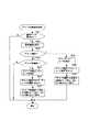
図6は、ハンディターミナルの全体動作を示したメインのフローチャートであり、トリガーキー(スキャン開始スイッチ)が操作された際に実行開始される。
先ず、CPU1は、ラベルなどに記録されている複数の2次元コードパターンをスキャンして光学的に読み取ってその1面分の画像データ(スキャンデータ)をコードパターン用のV−RAM10に書き込む(ステップS1)。このV−RAM10に書き込まれた画像データは、タッチパネル5a付きの表示装置5を構成するターミナル画面上にイメージ表示される(ステップS2)。この場合、1面分の画像データがそのままイメージ表示されるため、一度のスキャンで読み取られた複数のコードパターンは、その実物の配列状態のままイメージ表示される。FIG. 6 is a main flowchart showing the overall operation of the handy terminal, which is started when a trigger key (scan start switch) is operated.
First, the
ここで、CPU1は、この1面分の画像データを解析し、この画像データ内に含まれている各コードパターン毎に、その領域を順次特定しながら各コードパターン領域の始点座標および終点座標を特定すると共に、この始点座標、終点座標をコード位置テーブル12に「コード番号」に対応付けて「開始位置」、「終了位置」としてセットする(ステップS3)。この場合、コードパターン領域を順次特定するごとに「コード番号」を自動生成し、この「コード番号」を含む新たなレコードを生成し、この生成レコード内にコードパターン領域の始点座標および終点座標を「開始位置」、「終了位置」としてセットする動作を繰り返すようにしている。このようにして一度のスキャンで読み取られた複数のコードパターンに対応してその位置情報をコード位置テーブル12にセットする処理が終了した後は、デコード対象/デコード対象外の選択操作を受け付けてその選択状態を識別可能に案内表示する選択処理に移る (ステップS4)。 Here, the
図7は、上述のデコード対象/デコード対象外の選択処理を詳述するためのフローチャートであり、図8は、この場合の選択画面を示している。
先ず、選択キー(図8参照)STが操作された際には(ステップS21)、それに応答して選択画面を表示出力させる(ステップS22)。すなわち、図8に示すように、タッチパネル5a付きの表示装置5を構成するターミナル画面TD上に複数のコードパターンがイメージ表示されている状態において、デコード選択用の処理メニューが選択画面として表示出力される。この選択画面内の処理メニュー「1:デコード選択」、「2:デコード非選択」のうち、その何れかのメニュー項目が選択指定されると、ステップS23では、「1:デコード選択」のメニュー項目が指定されたか否かを判別する。FIG. 7 is a flowchart for explaining in detail the selection process for decoding / not decoding, and FIG. 8 shows a selection screen in this case.
First, when the selection key (see FIG. 8) ST is operated (step S21), a selection screen is displayed and output in response thereto (step S22). That is, as shown in FIG. 8, in the state where a plurality of code patterns are displayed on the terminal screen TD constituting the
いま、「1:デコード選択」が指定された場合において(ステップS23でYES)、ターミナル画面上でデコード対象を選択するためにそのコードパターンの表示位置がタッチ指定されると(ステップS28)、指定されたタッチ位置(コードパターン位置)を検出すると共に、この検出位置に基づいてコード位置テーブル12を検索することによって当該位置に対応するレコードを指定し、この指定レコード内の「デコード選択」の項目にデコード対象であることを示すフラグ“1”をセットする(ステップS29)。そして、この「フラグ1:デコード選択」に対応する識別マーク(実線の円形マーク)を図形データファイルから読み出すと共に、この指定コードパターンの位置を基準として、当該識別マークを識別マーク用のV−RAM11に書き込むことによって指定コードパターンのイメージ表示に対応付けて識別マークを合成表示させる(ステップS30)。この場合、指定コードパターンを囲むように実線の円形マークが付加表示される。 Now, when “1: decode selection” is designated (YES in step S23), if the display position of the code pattern is touch-designated on the terminal screen to select the decoding target (step S28), the designation is made. The detected touch position (code pattern position) is detected, the record corresponding to the position is specified by searching the code position table 12 based on the detected position, and the item of “decode selection” in the specified record A flag “1” indicating that it is a decoding target is set in (step S29). Then, an identification mark (solid circular mark) corresponding to “flag 1: decode selection” is read from the graphic data file, and the identification mark is used as a reference mark V-
また、「2:デコード非選択」が指定された場合において(ステップS24でYES)、ターミナル画面上でデコード対象外を選択するためにそのコードパターンの表示位置がタッチ指定されると(ステップS25)、指定されたタッチ位置(コードパターン位置)を検出すると共に、この検出位置に基づいてコード位置テーブル12を検索することによって当該位置に対応するレコードを指定し、この指定レコード内の「デコード選択」の項目にデコード対象外であることを示すフラグ“2”をセットする(ステップS26)。そして、この「フラグ2:デコード非選択」に対応する識別マーク(破線の円形マーク)を図形データファイルから読み出すと共に、この指定コードパターンの位置を基準として、当該識別マークを識別マーク用のV−RAM11に書き込むことによって指定コードパターンのイメージ表示に対応付けて識別マークを合成表示させる(ステップS27)。この場合においても、指定コードパターンを囲むように破線の円形マークが付加表示される。 When “2: Decode non-selected” is designated (YES in step S24), if the display position of the code pattern is touch-designated on the terminal screen to select a non-decoding target (step S25). The specified touch position (code pattern position) is detected, and the code position table 12 is searched based on the detected position to specify a record corresponding to the position, and “decode selection” in the specified record A flag “2” indicating that the item is not subject to decoding is set in the item (step S26). Then, an identification mark (dashed circular mark) corresponding to this “flag 2: decoding non-selected” is read from the graphic data file, and the identification mark is used as a reference mark V− based on the position of the designated code pattern. By writing in the
このような選択処理が終了し、図8に示した確定キー(選択内容の確定を指示するキー、言い換えれば、デコード開始を指示するキー)ETが操作されると(図6のステップS5)、CPU1は、コード位置テーブル12の内容をその先頭から1レコードごとに順次読み出すが、その際、ステップS6では、最終レコードまで全て読み出したか否かをチェックする。最初は、先頭レコードが読み出された場合であるから、このレコード内の「デコード選択」のフラグ内容をチェックし(ステップS7)、「フラグ2:デコード非選択」であれば、次ぎのレコードを読み出すが(ステップS14)、「フラグ1:デコード選択」であれば、当該レコード内の「開始位置」、「終了位置」によって特定される領域からコードパターンを切り出してデコードすると共に、正常にデコードされたか否かをチェックし、正常にデコードすることができた場合には、当該レコード内の「デコード結果」として「フラグ1:OK」をセットし、デコードに失敗した場合には、「フラグ2:NG」をセットする(ステップS9)。 When such a selection process is completed and the confirmation key (a key for confirming selection contents, in other words, a key for instructing the start of decoding) ET shown in FIG. 8 is operated (step S5 in FIG. 6), The
この場合、デコード結果が「フラグ1:OK」であれば(ステップS10でYES)、これに対応する識別マーク(二重の円形マーク)を図形データファイルから読み出すと共に、このコードパターンの位置を基準として、当該識別マークを識別マーク用のV−RAM11に書き込むことによって指定コードパターンのイメージ表示に対応付けて識別マークを合成表示させる(ステップS11)。この場合、指定コードパターンを囲むように二重の円形マークが付加表示される。そして、正常にデコードすることができたデコード結果を表示出力させる(ステップS13)。 In this case, if the decoding result is “flag 1: OK” (YES in step S10), the corresponding identification mark (double circular mark) is read from the graphic data file and the position of this code pattern is used as a reference. As a result, the identification mark is written in the V-
また、デコード結果が「フラグ2:NG」であれば(ステップS10でNO)、これに対応する識別マーク(×マーク)を図形データファイルから読み出すと共に、このコードパターンの位置を基準として、当該識別マークを識別マーク用のV−RAM11に書き込むことによって指定コードパターンのイメージ表示に対応付けて識別マークを合成表示させる(ステップS12)。この場合、指定コードパターン上に×マークを重ね合わせて付加表示される。
以下、コード位置テーブル12から次ぎのレコードを読み出し(ステップS14)、最終レコードまで全て読み出すまで(ステップS6でYES)、上述の動作が繰り返される(ステップS6〜S14)。If the decoding result is “flag 2: NG” (NO in step S10), the corresponding identification mark (× mark) is read out from the graphic data file, and the identification is performed based on the position of the code pattern. By writing the mark in the identification mark V-
Thereafter, the next record is read from the code position table 12 (step S14), and the above-described operation is repeated until the last record is read (YES in step S6) (steps S6 to S14).
図9は、デコード終了時点の表示内容を示した図である。
この場合、各コードパターンのイメージ表示に対応付けて表示されている識別マークによって以下の状態を確認することができる。すなわち、図中、二重の円形マークで囲まれたコードパターンは、デコード対象として選択指定され、かつ、正常にデコードすることができたコードパターンであることを確認することができる。この場合、コードパターンのイメージ表示とそのデコード結果とはターミナル画面TD内に並列的に表示されており、このデコード結果は、二重の円形マークで囲まれたコードパターンに対応するものであることを確認することが可能となる。また、破線の円形マークで囲まれたコードパターンは、デコード対象外として選択指定されたコードパターンであることを確認することができる。さらに、×マークが付されたコードパターンは、デコード対象として選択指定されたが、そのデコードに失敗したコードパターンであることを確認することができる。FIG. 9 is a diagram showing the display contents at the end of decoding.
In this case, the following state can be confirmed by the identification mark displayed in association with the image display of each code pattern. That is, in the figure, it can be confirmed that a code pattern surrounded by double circular marks is a code pattern that is selected and designated as a decoding target and that can be normally decoded. In this case, the image display of the code pattern and the decoding result thereof are displayed in parallel in the terminal screen TD, and the decoding result corresponds to the code pattern surrounded by double circular marks. Can be confirmed. Further, it is possible to confirm that the code pattern surrounded by the broken-line circular mark is a code pattern selected and designated as not to be decoded. Further, it is possible to confirm that the code pattern to which the “x” mark is attached is selected and designated as a decoding target but has failed to be decoded.
以上のように、この実施例のハンディターミナルにおいてCPU1は、トリガー操作に応答し、イメージスキャナ7によって複数のコードパターンが一度に読み取られた場合に、各コードパターン毎にデコード処理を行うと共にそのデコード結果に基づいて正常にデコードされたか否かを特定し、この特定状態を各コードパターンのイメージ表示に対応付けて識別可能に表示するようにしたから、一度に読み取った複数のコードパターンがイメージ表示されている画面上において、正常にデコードされたコードパターンを容易に確認することができ、コードパターンとデコード結果との対応関係を見間違えることを効果的に防止することが可能となる。 As described above, in the handy terminal of this embodiment, when the
この場合、一度に読み取られた複数のコードパターンがイメージ表示されている画面上において、どのコードパターンをデコード対象とするか否かが任意に選択指定された場合に、選択されたデコード対象の可否を各コードパターンのイメージ表示に対応付けて識別可能に案内表示するようにしたから、デコード対象として任意に選択指定されたコードパターンを容易に確認することができると共に、デコード処理後においては、次ぎの3種類の識別が可能となる。すなわち、デコード対象として選択指定され、かつ、正常にデコードすることができたコードパターンを識別することができ、デコード対象外として選択指定されたコードパターンを識別することができ、デコード対象として選択指定されたが、そのデコードに失敗したコードパターンを識別することができる。 In this case, if any code pattern to be decoded is arbitrarily selected and specified on the screen on which a plurality of code patterns read at once are displayed as images, whether or not the selected decoding target is possible Is displayed in an identifiable manner in association with the image display of each code pattern, so that a code pattern arbitrarily selected and designated as a decoding target can be easily confirmed. These three types of identification are possible. In other words, it is possible to identify a code pattern that has been selected and designated as a decoding target and has been successfully decoded, and a code pattern that has been selected and designated as a non-decoding target can be identified, and can be selected and designated as a decoding target. However, it is possible to identify the code pattern that has failed to be decoded.
また、デコード対象とするか否かが任意に選択指定された場合に、この選択内容を示す識別マーク、正常にデコードされたか否かを示す識別マークを各コードパターンのイメージ表示に対応付けて付加表示するようにしたから、正常にデコードされたか否かを直感的に確認することが可能となると共に、4種類の識別マークを使い分けることによって色々な状態を案内することができる。 Also, when it is arbitrarily selected and specified whether or not to be decoded, an identification mark indicating this selection content and an identification mark indicating whether or not decoding has been normally performed are added in association with the image display of each code pattern. Since it is displayed, it is possible to intuitively check whether or not the decoding has been normally performed, and various states can be guided by properly using four types of identification marks.
一方、この実施例のハンディターミナルにおいてCPU1は、トリガー操作に応答し、イメージスキャナ7によって複数のコードパターンが一度に読み取られた場合に各コードパターンをイメージ表示すると共に、この複数のコードパターンがイメージ表示されている画面上において、どのコードパターンをデコード対象とするか否かが任意に選択指定された場合に、この選択状態を各コードパターンのイメージに対応付けて識別可能に案内表示するようにしたから、一度に読み取った複数のコードパターンがイメージ表示されている画面上において、デコード対象あるいはデコード対象外として任意に選択指定されたコードパターンを容易に確認することができる。この場合、デコード対象として選択されたコードパターンをデコード処理すると共に、そのデコード結果を表示するようにしたから、読み取り対象外のコードパターンを含めて読み取ってしまったような場合でも、所望するコードパターンのデコード結果のみが表示されるため、デコード結果を見間違えることもない。 On the other hand, in the handy terminal of this embodiment, the
なお、上述した実施例においては、イメージスキャナ7によって複数のコードパターンが一度に読み取られた場合を前提としたが、1つのコードパターンを読み取った場合か、複数のコードパターンを一度に読み取った場合かを自動的に判別し、複数のコードパターンを読み取ったことを検出した場合に、各コードパターンのイメージ表示に対応付けて所定の識別マークを合成表示するようにしてもよい。この場合、1スキャン分の画像データを解析することによって当該画像データ内に含まれているコードパターンの数を計数するようにすればよい。 In the above-described embodiment, it is assumed that a plurality of code patterns are read at a time by the
また、上述した図9においては、二重の円形マークで囲まれたコードパターン、つまり、デコード対象として選択指定され、かつ、正常にデコードすることができたコードパターンが1つの場合を例示したが、二重の円形マークで囲まれたコードパターンが複数個表示されている場合において、現在表示されているデコード結果は、この複数個のコードパターンのうち、何れのコードパターンに対応するものかを識別可能とするために、当該コードパターンを囲む二重の円形マークを点滅表示によって明示するようにしてもよい。この場合、切り換え操作に応答して次ぎのデコード結果に切り換え表示させると共に、それに連動して円形マークの点滅表示も切り換えるようにしてもよい。 Further, in FIG. 9 described above, the code pattern surrounded by double circular marks, that is, the case where there is one code pattern that is selected and designated as a decoding target and can be normally decoded is illustrated. When a plurality of code patterns surrounded by double circular marks are displayed, the currently displayed decoding result indicates which of the plurality of code patterns corresponds to the code pattern. In order to enable identification, a double circular mark surrounding the code pattern may be clearly indicated by blinking display. In this case, in response to the switching operation, the next decoding result may be switched and displayed, and the blinking display of the circular mark may be switched in conjunction with it.
上述した実施例においては、選択画面上においてデコード対象およびデコード対象外を選択可能としたが、その何れか一方を選択するようにしてもよい。
また、上述した実施例においては、識別マークとして、実線の円形マーク、破線の円形マーク、二重の円形マーク、×マークを合成表示するようにしたが、識別マークの形状は任意であり、また、識別マークの表示位置も任意であり、コードパターンと識別マークとの対応関係を明示できれば、コードパターンの下側、上側などに付加表示するようにしてもよい。In the embodiment described above, the decoding target and the non-decoding target can be selected on the selection screen, but either one of them may be selected.
In the above-described embodiment, a solid circle mark, a dashed circle mark, a double circle mark, and a x mark are combined and displayed as identification marks. However, the shape of the identification mark is arbitrary, The display position of the identification mark is also arbitrary. If the correspondence between the code pattern and the identification mark can be clearly shown, it may be additionally displayed on the lower side or the upper side of the code pattern.
また、識別マークの合成表示に限らず、コードパターン自体を点滅表示させたり、コードパターン自体の表示輝度を変化させることよって識別可能としてもよく、さらには、正常にデコードされたコードパターン、デコード対象として選択されたコードパターンのみを識別表示するようにしてもよく、逆に、デコードに失敗したコードパターン、非選択のコードパターンのみを識別表示するようにしてもよい。 In addition to the composite display of the identification mark, the code pattern itself may be displayed in a blinking manner, or may be identified by changing the display brightness of the code pattern itself. Only the selected code pattern may be identified and displayed, and conversely, only the code pattern that failed to be decoded or the unselected code pattern may be identified and displayed.
その他、スキャナの種類は限定せず、CMOSイメージセンサを備えたイメージキャプチャ式のスキャナのほか、レーザビーム式のスキャナ、CCDイメージセンサを備えたデジタルスチルカメラ式のスキャナであってもよく、さらに、ハンディ式のスキャナに限らず、定置式のスキャナであってもよい。
さらに、コード読取装置の各構成要素を2以上の筐体に物理的に分離し、通信回線、ケーブル等の有線伝送路あるいは電波、マイクロウエーブ、赤外線等の無線伝送路を介してデータを送受信するコード読取装置であってもよい。In addition, the type of scanner is not limited, and may be an image capture type scanner equipped with a CMOS image sensor, a laser beam type scanner, a digital still camera type scanner equipped with a CCD image sensor, The scanner is not limited to a handy scanner, and may be a stationary scanner.
Furthermore, each component of the code reader is physically separated into two or more cases, and data is transmitted / received via a wired transmission line such as a communication line or cable, or a wireless transmission line such as radio waves, microwaves, or infrared rays. It may be a code reader.
一方、コンピュータに対して、上述した各手段を実行させるためのプログラムコードをそれぞれ記録した記録媒体(たとえば、CD−ROM、フレキシブルディスク、RAMカード等)を提供するようにしてもよい。すなわち、コンピュータが読み取り可能なプログラムコードを有する記録媒体であって、コード読み取りの指示に応答して複数のコードパターンが一度に読み取られた場合に、各コードパターン毎にデコード処理を行うと共にそのデコード結果に基づいて正常にデコードされたか否かを特定する機能と、各コードパターン毎に正常にデコードされたか否かが特定された場合に、この特定状態を各コードパターンのイメージ表示に対応付けて識別可能に表示する機能とを実現させるためのプログラムを記録したコンピュータが読み取り可能な記録媒体を提供するようにしてもよい。 On the other hand, a recording medium (for example, a CD-ROM, a flexible disk, a RAM card, etc.) on which program codes for executing the above-described units are recorded may be provided to the computer. That is, a recording medium having a computer-readable program code, and when a plurality of code patterns are read at a time in response to a code reading instruction, the decoding process is performed for each code pattern and the decoding is performed. When it is specified whether or not the function has been normally decoded based on the result and whether or not each code pattern has been normally decoded, this specific state is associated with the image display of each code pattern. You may make it provide the computer-readable recording medium which recorded the program for implement | achieving the function to display so that identification is possible.
また、コンピュータが読み取り可能なプログラムコードを有する記録媒体であって、コード読み取りの指示に応答して複数のコードパターンが一度に読み取られた場合に、各コードパターンをイメージ表示する機能と、前記複数のコードパターンがイメージ表示されている画面上において、どのコードパターンをデコード対象とするか否かが任意に選択指定された場合に、このデコード対象の可否を各コードパターンのイメージ表示に対応付けて識別可能に案内表示する機能と、この案内表示後においてデコード指示を受け付けたことを条件に、デコード対象として選択されたコードパターンをデコード処理すると共に、そのデコード結果を表示する機能とを実現させるためのプログラムを記録したコンピュータが読み取り可能な記録媒体を提供するようにしてもよい。 A computer-readable recording medium having a program code, wherein a plurality of code patterns are read at a time in response to a code reading instruction; On the screen where the code pattern is displayed as an image, when it is arbitrarily selected and specified which code pattern is to be decoded, this decoding pattern is associated with the image display of each code pattern. In order to realize a function for displaying information in an identifiable manner and a function for decoding a code pattern selected as a decoding target and displaying the decoding result on the condition that a decoding instruction is received after the guidance display. A computer-readable recording medium on which the program is recorded It may be subjected.
1 CPU
2 ROM
3 RAM
4 キー入力装置
5a タッチパネル
5 表示装置
7 イメージスキャナ
10 コードパターン用のV−RAM
11 識別マーク用のV−RAM
12 コード位置テーブル
ST 選択キー
ET 確定キー
TD ターミナル画面1 CPU
2 ROM
3 RAM
4
11 V-RAM for identification mark
12 Code position table ST selection key ET confirmation key TD terminal screen
Claims (7)
Translated fromJapaneseコード読み取りの指示に応答して複数のコードパターンが一度に読み取られた場合に、各コードパターン毎にデコード処理を行うと共にそのデコード結果に基づいて正常にデコードされたか否かを特定するデコード処理手段と、
このデコード処理手段によって各コードパターン毎に正常にデコードされたか否かが特定された場合に、この特定状態を各コードパターンのイメージ表示に対応付けて識別可能に表示する表示手段と、
を具備したことを特徴とするコード読取装置。In the code reading device that reads and decodes the code pattern and displays the decoding result,
When a plurality of code patterns are read at a time in response to a code reading instruction, a decoding processing means for performing decoding processing for each code pattern and specifying whether or not decoding is normally performed based on the decoding result When,
When it is specified whether or not each code pattern is normally decoded by this decoding processing means, display means for displaying this specific state in an identifiable manner in association with the image display of each code pattern;
A code reading device comprising:
ようにしたことを特徴とする請求項1記載のコード読取装置。The display means displays a specific mark indicating whether or not the decoding has been normally performed on the image display of each code pattern when displaying whether or not the decoding is normally performed corresponding to the image display of each code pattern. Additional display in association,
2. The code reading device according to claim 1, wherein the code reading device is configured as described above.
前記複数のコードパターンがイメージ表示されている画面上において、前記選択手段によって選択されたデコード対象の可否を各コードパターンのイメージ表示に対応付けて識別可能に案内表示する案内手段と、
を設け、前記デコード処理手段は、前記選択手段によってデコード対象として選択されたコードパターン毎にデコード処理を行うと共にそのデコード結果に基づいて正常にデコードされたか否かを特定する、
ようにしたことを特徴とする請求項1記載のコード読取装置。A selection means for arbitrarily selecting and specifying which code pattern is to be decoded on a screen on which a plurality of code patterns read at a time are displayed as images;
On the screen on which the plurality of code patterns are displayed as images, guide means for displaying the possibility of decoding selected by the selection means in an identifiable manner in association with the image display of each code pattern;
The decoding processing means performs decoding processing for each code pattern selected as a decoding target by the selection means and specifies whether or not the decoding has been normally performed based on the decoding result.
The code reader according to claim 1, which is configured as described above.
コード読み取りの指示に応答して複数のコードパターンが一度に読み取られた場合に、各コードパターン毎にデコード処理を行うと共にそのデコード結果に基づいて正常にデコードされたか否かを特定する機能と、
各コードパターン毎に正常にデコードされたか否かが特定された場合に、この特定状態を各コードパターンのイメージ表示に対応付けて識別可能に表示する機能と、
を実現させるためのプログラム。Against the computer,
When a plurality of code patterns are read at a time in response to a code reading instruction, a function for performing decoding processing for each code pattern and specifying whether or not the decoding has been normally performed based on the decoding result;
When it is specified whether or not each code pattern has been normally decoded, the function of displaying this specific state in an identifiable manner in association with the image display of each code pattern;
A program to realize
コード読み取りの指示に応答して複数のコードパターンが一度に読み取られた場合に、各コードパターンをイメージ表示するコードパターン表示手段と、
前記複数のコードパターンがイメージ表示されている画面上において、どのコードパターンをデコード対象とするか否かを任意に選択指定する選択手段と、
前記複数のコードパターンがイメージ表示されている画面上において、前記選択手段によって選択されたデコード対象の可否を各コードパターンのイメージ表示に対応付けて識別可能に案内表示する案内手段と、
この案内表示後においてデコード指示を受け付けたことを条件に、前記選択手段によってデコード対象として選択されたコードパターンをデコード処理すると共に、そのデコード結果を表示するデコード処理手段と、
を具備したことを特徴とするコード読取装置。In the code reading device that reads and decodes the code pattern and displays the decoding result,
Code pattern display means for displaying an image of each code pattern when a plurality of code patterns are read at once in response to a code reading instruction;
A selection means for arbitrarily selecting and designating which code pattern is to be decoded on a screen on which the plurality of code patterns are displayed as images;
On the screen on which the plurality of code patterns are displayed as images, guide means for displaying the possibility of decoding selected by the selection means in an identifiable manner in association with the image display of each code pattern;
Decoding processing means for decoding the code pattern selected as a decoding target by the selection means on the condition that a decoding instruction is received after the guidance display, and displaying the decoding result;
A code reading device comprising:
ようにしたことを特徴とする請求項5記載のコード読取装置。The guide means displays a specific mark indicating whether or not to be decoded in an image display of each code pattern when displaying the possibility or not of the decoding target arbitrarily selected and specified in association with the image display of each code pattern. Additional display in association,
6. The code reader according to claim 5, wherein the code reader is configured as described above.
コード読み取りの指示に応答して複数のコードパターンが一度に読み取られた場合に、各コードパターンをイメージ表示する機能と、
前記複数のコードパターンがイメージ表示されている画面上において、どのコードパターンをデコード対象とするか否かが任意に選択指定する機能と、
前記複数のコードパターンがイメージ表示されている画面上において、どのコードパターンをデコード対象とするか否かが任意に選択指定された場合に、このデコード対象の可否を各コードパターンのイメージ表示に対応付けて識別可能に案内表示する機能と、
この案内表示後においてデコード指示を受け付けたことを条件に、デコード対象として選択されたコードパターンをデコード処理すると共に、そのデコード結果を表示する機能と、
を実現させるためのプログラム。Against the computer,
A function to display each code pattern as an image when multiple code patterns are read at once in response to a code reading instruction;
On the screen on which the plurality of code patterns are displayed as images, a function to arbitrarily select and specify which code pattern is to be decoded; and
On the screen where the plurality of code patterns are displayed as an image, if any code pattern is selected and specified as a decoding target, this decoding pattern can be displayed on each code pattern. A function to display the information in an identifiable manner
A function of decoding the code pattern selected as a decoding target on the condition that a decoding instruction is received after the guidance display, and displaying the decoding result;
A program to realize
Priority Applications (2)
| Application Number | Priority Date | Filing Date | Title |
|---|---|---|---|
| JP2004177833AJP4192847B2 (en) | 2004-06-16 | 2004-06-16 | Code reader and program |
| US11/153,634US7611059B2 (en) | 2004-06-16 | 2005-06-15 | Code reading device and program |
Applications Claiming Priority (1)
| Application Number | Priority Date | Filing Date | Title |
|---|---|---|---|
| JP2004177833AJP4192847B2 (en) | 2004-06-16 | 2004-06-16 | Code reader and program |
Publications (2)
| Publication Number | Publication Date |
|---|---|
| JP2006004037Atrue JP2006004037A (en) | 2006-01-05 |
| JP4192847B2 JP4192847B2 (en) | 2008-12-10 |
Family
ID=35479584
Family Applications (1)
| Application Number | Title | Priority Date | Filing Date |
|---|---|---|---|
| JP2004177833AExpired - Fee RelatedJP4192847B2 (en) | 2004-06-16 | 2004-06-16 | Code reader and program |
Country Status (2)
| Country | Link |
|---|---|
| US (1) | US7611059B2 (en) |
| JP (1) | JP4192847B2 (en) |
Cited By (26)
| Publication number | Priority date | Publication date | Assignee | Title |
|---|---|---|---|---|
| JP2009020813A (en)* | 2007-07-13 | 2009-01-29 | Three M Innovative Properties Co | Tag and article identification system using the same |
| JP2009039163A (en)* | 2007-08-06 | 2009-02-26 | Sega Corp | Game device |
| JP2009151446A (en)* | 2007-12-19 | 2009-07-09 | Denso Wave Inc | Optical information reading device |
| JP2010049595A (en)* | 2008-08-25 | 2010-03-04 | Casio Comput Co Ltd | Scanner apparatus and program |
| JP2010079688A (en)* | 2008-09-26 | 2010-04-08 | Casio Hitachi Mobile Communications Co Ltd | Terminal device and program |
| JP2010176619A (en)* | 2009-02-02 | 2010-08-12 | Casio Computer Co Ltd | Symbol reader and program |
| JP2010176620A (en)* | 2009-02-02 | 2010-08-12 | Casio Computer Co Ltd | Symbol reading device, symbol reading system, and program |
| JP2011248917A (en)* | 2011-07-21 | 2011-12-08 | Toshiba Tec Corp | Commodity sales registration data processing device |
| JP2012053550A (en)* | 2010-08-31 | 2012-03-15 | Casio Comput Co Ltd | Information reading device and program |
| JP2012064110A (en)* | 2010-09-17 | 2012-03-29 | Casio Comput Co Ltd | Information reading apparatus and program |
| JP2012118743A (en)* | 2010-11-30 | 2012-06-21 | Toshiba Corp | Ticket medium and ticket medium processing apparatus |
| JP2013012226A (en)* | 2012-08-30 | 2013-01-17 | Casio Comput Co Ltd | Image processing apparatus and program |
| JP2013235607A (en)* | 2013-07-18 | 2013-11-21 | Casio Comput Co Ltd | Image processing apparatus and program |
| JP2014099176A (en)* | 2012-11-15 | 2014-05-29 | Hand Held Products Inc | Mobile computer configured to read multiple decodable indicia |
| JP2014110024A (en)* | 2012-12-04 | 2014-06-12 | Sharp Corp | Display device |
| JP2014225298A (en)* | 2014-08-27 | 2014-12-04 | カシオ計算機株式会社 | Identification device and program |
| JP2016081082A (en)* | 2014-10-09 | 2016-05-16 | 共同印刷株式会社 | Method, device, and program |
| JP2018500692A (en)* | 2014-12-29 | 2018-01-11 | アリババ・グループ・ホールディング・リミテッドAlibaba Group Holding Limited | Information display method and apparatus |
| WO2018164301A1 (en)* | 2017-03-09 | 2018-09-13 | 엘지전자 주식회사 | Mobile terminal |
| CN109388986A (en)* | 2017-08-10 | 2019-02-26 | 卡西欧计算机株式会社 | Barcode reading device, control method, and computer-readable storage medium |
| JP2019128677A (en)* | 2018-01-22 | 2019-08-01 | 株式会社デンソーウェーブ | Information code generation system |
| JP2019128676A (en)* | 2018-01-22 | 2019-08-01 | 株式会社デンソーウェーブ | Information code generation system |
| JP2019179345A (en)* | 2018-03-30 | 2019-10-17 | 株式会社デンソーウェーブ | Information code reader |
| CN110756998A (en)* | 2019-09-25 | 2020-02-07 | 大族激光科技产业集团股份有限公司 | Method for laser marking on surface of product |
| JP2021520017A (en)* | 2018-10-22 | 2021-08-12 | ▲騰▼▲訊▼科技(深▲セン▼)有限公司 | Graphic code recognition method and device, as well as terminals and programs |
| JP2023551045A (en)* | 2020-11-30 | 2023-12-06 | アエスキュラップ アーゲー | Methods, reading equipment, and reading systems for capturing computer-readable codes |
Families Citing this family (16)
| Publication number | Priority date | Publication date | Assignee | Title |
|---|---|---|---|---|
| US7331524B2 (en)* | 2005-05-31 | 2008-02-19 | Symbol Technologies, Inc. | Feedback mechanism for scanner devices |
| KR100828539B1 (en)* | 2005-09-20 | 2008-05-13 | 후지제롯쿠스 가부시끼가이샤 | A storage medium storing a two-dimensional code detection method, a detection device, and a detection program |
| JP4911340B2 (en)* | 2006-02-10 | 2012-04-04 | 富士ゼロックス株式会社 | Two-dimensional code detection system and two-dimensional code detection program |
| US8016198B2 (en)* | 2007-10-09 | 2011-09-13 | Hewlett-Packard Development Company, L.P. | Alignment and non-alignment assist images |
| JP5183767B2 (en)* | 2010-09-01 | 2013-04-17 | 東芝テック株式会社 | Code reader and program |
| US10528772B1 (en) | 2012-02-24 | 2020-01-07 | Socket Mobile, Inc. | Assisted aimer for optimized symbol scanning by a portable computing device having an integral camera |
| US8944313B2 (en) | 2012-06-29 | 2015-02-03 | Honeywell International Inc. | Computer configured to display multimedia content |
| US9064168B2 (en)* | 2012-12-14 | 2015-06-23 | Hand Held Products, Inc. | Selective output of decoded message data |
| US9208367B2 (en)* | 2012-11-15 | 2015-12-08 | Hand Held Products | Mobile computer configured to read multiple decodable indicia |
| JP6028555B2 (en)* | 2012-12-12 | 2016-11-16 | ソニー株式会社 | Information processing apparatus, program, and information processing method |
| US9773142B2 (en)* | 2013-07-22 | 2017-09-26 | Hand Held Products, Inc. | System and method for selectively reading code symbols |
| US9830488B2 (en)* | 2014-12-30 | 2017-11-28 | Hand Held Products, Inc. | Real-time adjustable window feature for barcode scanning and process of scanning barcode with adjustable window feature |
| US10152622B2 (en)* | 2014-12-30 | 2018-12-11 | Hand Held Products, Inc. | Visual feedback for code readers |
| USD754663S1 (en)* | 2015-02-19 | 2016-04-26 | Contract Datascan, Lp | Handheld scanner |
| JP2018005091A (en)* | 2016-07-06 | 2018-01-11 | 富士通株式会社 | Display control program, display control method and display controller |
| JP7199845B2 (en)* | 2018-06-19 | 2023-01-06 | キヤノン株式会社 | Image processing device, image processing method and program |
Citations (2)
| Publication number | Priority date | Publication date | Assignee | Title |
|---|---|---|---|---|
| JP2001028033A (en)* | 1999-07-14 | 2001-01-30 | Oki Electric Ind Co Ltd | Display method for bar code recognition result and bar code recognition device |
| JP2004110670A (en)* | 2002-09-20 | 2004-04-08 | Denso Wave Inc | Information code reader |
Family Cites Families (5)
| Publication number | Priority date | Publication date | Assignee | Title |
|---|---|---|---|---|
| US5192854A (en)* | 1990-07-26 | 1993-03-09 | Counts Reginald D | System for electronically recording and redeeming coupons |
| US5237163A (en) | 1992-01-06 | 1993-08-17 | Ncr Corporation | Method for scanning a plurality of bar code labels |
| US20030089775A1 (en)* | 2001-05-21 | 2003-05-15 | Welch Allyn Data Collection, Inc. | Display-equipped optical reader having decode failure image display feedback mode |
| US6834807B2 (en)* | 2001-07-13 | 2004-12-28 | Hand Held Products, Inc. | Optical reader having a color imager |
| JP3548783B2 (en)* | 2002-12-10 | 2004-07-28 | オムロン株式会社 | Optical code reading method and device |
- 2004
- 2004-06-16JPJP2004177833Apatent/JP4192847B2/ennot_activeExpired - Fee Related
- 2005
- 2005-06-15USUS11/153,634patent/US7611059B2/enactiveActive
Patent Citations (2)
| Publication number | Priority date | Publication date | Assignee | Title |
|---|---|---|---|---|
| JP2001028033A (en)* | 1999-07-14 | 2001-01-30 | Oki Electric Ind Co Ltd | Display method for bar code recognition result and bar code recognition device |
| JP2004110670A (en)* | 2002-09-20 | 2004-04-08 | Denso Wave Inc | Information code reader |
Cited By (37)
| Publication number | Priority date | Publication date | Assignee | Title |
|---|---|---|---|---|
| JP2009020813A (en)* | 2007-07-13 | 2009-01-29 | Three M Innovative Properties Co | Tag and article identification system using the same |
| JP2009039163A (en)* | 2007-08-06 | 2009-02-26 | Sega Corp | Game device |
| JP2009151446A (en)* | 2007-12-19 | 2009-07-09 | Denso Wave Inc | Optical information reading device |
| JP2010049595A (en)* | 2008-08-25 | 2010-03-04 | Casio Comput Co Ltd | Scanner apparatus and program |
| JP2010079688A (en)* | 2008-09-26 | 2010-04-08 | Casio Hitachi Mobile Communications Co Ltd | Terminal device and program |
| JP2010176619A (en)* | 2009-02-02 | 2010-08-12 | Casio Computer Co Ltd | Symbol reader and program |
| JP2010176620A (en)* | 2009-02-02 | 2010-08-12 | Casio Computer Co Ltd | Symbol reading device, symbol reading system, and program |
| JP2012053550A (en)* | 2010-08-31 | 2012-03-15 | Casio Comput Co Ltd | Information reading device and program |
| JP2012064110A (en)* | 2010-09-17 | 2012-03-29 | Casio Comput Co Ltd | Information reading apparatus and program |
| JP2012118743A (en)* | 2010-11-30 | 2012-06-21 | Toshiba Corp | Ticket medium and ticket medium processing apparatus |
| JP2011248917A (en)* | 2011-07-21 | 2011-12-08 | Toshiba Tec Corp | Commodity sales registration data processing device |
| JP2013012226A (en)* | 2012-08-30 | 2013-01-17 | Casio Comput Co Ltd | Image processing apparatus and program |
| JP2018139141A (en)* | 2012-11-15 | 2018-09-06 | ハンド ヘルド プロダクツ インコーポレーティッド | Method for processing multiple decodable indicia |
| JP2023001179A (en)* | 2012-11-15 | 2023-01-04 | ハンド ヘルド プロダクツ インコーポレーティッド | Method for processing multiple decodable indicia |
| JP7460728B2 (en) | 2012-11-15 | 2024-04-02 | ハンド ヘルド プロダクツ インコーポレーティッド | Method for handling large numbers of decodable indicia |
| JP2014099176A (en)* | 2012-11-15 | 2014-05-29 | Hand Held Products Inc | Mobile computer configured to read multiple decodable indicia |
| JP7096804B2 (en) | 2012-11-15 | 2022-07-06 | ハンド ヘルド プロダクツ インコーポレーティッド | How to process a large number of decryptable stamps |
| JP2022002124A (en)* | 2012-11-15 | 2022-01-06 | ハンド ヘルド プロダクツ インコーポレーティッド | Method for processing multiple decodable indicia |
| JP2020021511A (en)* | 2012-11-15 | 2020-02-06 | ハンド ヘルド プロダクツ インコーポレーティッド | Method for processing multiple decodable indicia |
| JP2014110024A (en)* | 2012-12-04 | 2014-06-12 | Sharp Corp | Display device |
| JP2013235607A (en)* | 2013-07-18 | 2013-11-21 | Casio Comput Co Ltd | Image processing apparatus and program |
| JP2014225298A (en)* | 2014-08-27 | 2014-12-04 | カシオ計算機株式会社 | Identification device and program |
| JP2016081082A (en)* | 2014-10-09 | 2016-05-16 | 共同印刷株式会社 | Method, device, and program |
| US10394755B2 (en) | 2014-12-29 | 2019-08-27 | Alibaba Group Holding Limited | Information presentation method and apparatus |
| JP2018500692A (en)* | 2014-12-29 | 2018-01-11 | アリババ・グループ・ホールディング・リミテッドAlibaba Group Holding Limited | Information display method and apparatus |
| WO2018164301A1 (en)* | 2017-03-09 | 2018-09-13 | 엘지전자 주식회사 | Mobile terminal |
| US11645644B2 (en) | 2017-03-09 | 2023-05-09 | Lg Electronics Inc. | Mobile terminal |
| CN109388986A (en)* | 2017-08-10 | 2019-02-26 | 卡西欧计算机株式会社 | Barcode reading device, control method, and computer-readable storage medium |
| JP7246134B2 (en) | 2018-01-22 | 2023-03-27 | 株式会社デンソーウェーブ | Information code generation system |
| JP2019128676A (en)* | 2018-01-22 | 2019-08-01 | 株式会社デンソーウェーブ | Information code generation system |
| JP2019128677A (en)* | 2018-01-22 | 2019-08-01 | 株式会社デンソーウェーブ | Information code generation system |
| JP2019179345A (en)* | 2018-03-30 | 2019-10-17 | 株式会社デンソーウェーブ | Information code reader |
| JP2021520017A (en)* | 2018-10-22 | 2021-08-12 | ▲騰▼▲訊▼科技(深▲セン▼)有限公司 | Graphic code recognition method and device, as well as terminals and programs |
| JP7118244B2 (en) | 2018-10-22 | 2022-08-15 | ▲騰▼▲訊▼科技(深▲セン▼)有限公司 | Graphic code recognition method and device, terminal and program |
| CN110756998A (en)* | 2019-09-25 | 2020-02-07 | 大族激光科技产业集团股份有限公司 | Method for laser marking on surface of product |
| JP2023551045A (en)* | 2020-11-30 | 2023-12-06 | アエスキュラップ アーゲー | Methods, reading equipment, and reading systems for capturing computer-readable codes |
| JP7665750B2 (en) | 2020-11-30 | 2025-04-21 | アエスキュラップ アーゲー | Method, reading device, and reading system for capturing computer readable codes - Patents.com |
Also Published As
| Publication number | Publication date |
|---|---|
| US20050279832A1 (en) | 2005-12-22 |
| JP4192847B2 (en) | 2008-12-10 |
| US7611059B2 (en) | 2009-11-03 |
Similar Documents
| Publication | Publication Date | Title |
|---|---|---|
| JP4192847B2 (en) | Code reader and program | |
| US8397992B2 (en) | Optical reader having image sensor for reading decodable indicia | |
| US7111787B2 (en) | Multimode image capturing and decoding optical reader | |
| US20040206821A1 (en) | Autodiscriminating bar code reading apparatus having solid state image sensor | |
| EP3482291B1 (en) | A device for generating computer programs and a method for generating computer programs | |
| US20040262394A1 (en) | Optical reader having solid-state image sensor | |
| WO2016152891A1 (en) | Image processing device, image processing method, and program | |
| JP2006250998A (en) | Image display system | |
| JP2018026025A (en) | Code reading device, control program and control method | |
| JP5780219B2 (en) | Information terminal and program | |
| JP2007179372A (en) | Composite barcode and barcode reading method | |
| JPH10222599A (en) | Optical reader | |
| JP6879329B2 (en) | Image processing device, image processing method, and program | |
| JP6056915B2 (en) | Information terminal and program | |
| JP2002133367A (en) | Character recognition device | |
| JP2009087215A (en) | Optical recognition code reading method, device and program | |
| JP2018010555A (en) | Code reading apparatus, code reading program, and code reading method | |
| JP2017073159A (en) | Information terminal and program | |
| WO2001016867A1 (en) | Optical reader system comprising local host processor and optical reader |
Legal Events
| Date | Code | Title | Description |
|---|---|---|---|
| RD02 | Notification of acceptance of power of attorney | Free format text:JAPANESE INTERMEDIATE CODE: A7422 Effective date:20060209 | |
| RD04 | Notification of resignation of power of attorney | Free format text:JAPANESE INTERMEDIATE CODE: A7424 Effective date:20060314 | |
| A977 | Report on retrieval | Free format text:JAPANESE INTERMEDIATE CODE: A971007 Effective date:20071025 | |
| A131 | Notification of reasons for refusal | Free format text:JAPANESE INTERMEDIATE CODE: A131 Effective date:20071106 | |
| A521 | Request for written amendment filed | Free format text:JAPANESE INTERMEDIATE CODE: A523 Effective date:20071211 | |
| RD04 | Notification of resignation of power of attorney | Free format text:JAPANESE INTERMEDIATE CODE: A7424 Effective date:20080519 | |
| TRDD | Decision of grant or rejection written | ||
| A01 | Written decision to grant a patent or to grant a registration (utility model) | Free format text:JAPANESE INTERMEDIATE CODE: A01 Effective date:20080826 | |
| A01 | Written decision to grant a patent or to grant a registration (utility model) | Free format text:JAPANESE INTERMEDIATE CODE: A01 | |
| A61 | First payment of annual fees (during grant procedure) | Free format text:JAPANESE INTERMEDIATE CODE: A61 Effective date:20080908 | |
| R150 | Certificate of patent or registration of utility model | Ref document number:4192847 Country of ref document:JP Free format text:JAPANESE INTERMEDIATE CODE: R150 Free format text:JAPANESE INTERMEDIATE CODE: R150 | |
| FPAY | Renewal fee payment (event date is renewal date of database) | Free format text:PAYMENT UNTIL: 20111003 Year of fee payment:3 | |
| FPAY | Renewal fee payment (event date is renewal date of database) | Free format text:PAYMENT UNTIL: 20121003 Year of fee payment:4 | |
| FPAY | Renewal fee payment (event date is renewal date of database) | Free format text:PAYMENT UNTIL: 20121003 Year of fee payment:4 | |
| FPAY | Renewal fee payment (event date is renewal date of database) | Free format text:PAYMENT UNTIL: 20131003 Year of fee payment:5 | |
| LAPS | Cancellation because of no payment of annual fees |