JP2006000651A - Improved surgical fastener - Google Patents
Improved surgical fastenerDownload PDFInfo
- Publication number
- JP2006000651A JP2006000651AJP2005175483AJP2005175483AJP2006000651AJP 2006000651 AJP2006000651 AJP 2006000651AJP 2005175483 AJP2005175483 AJP 2005175483AJP 2005175483 AJP2005175483 AJP 2005175483AJP 2006000651 AJP2006000651 AJP 2006000651A
- Authority
- JP
- Japan
- Prior art keywords
- material layer
- shape
- fastener
- legs
- staple
- Prior art date
- Legal status (The legal status is an assumption and is not a legal conclusion. Google has not performed a legal analysis and makes no representation as to the accuracy of the status listed.)
- Pending
Links
- 239000000463materialSubstances0.000claimsabstractdescription178
- 238000009792diffusion processMethods0.000claimsabstractdescription10
- 239000013013elastic materialSubstances0.000claimsabstractdescription10
- 229910001000nickel titaniumInorganic materials0.000claimsdescription21
- 239000010936titaniumSubstances0.000claimsdescription19
- 229910052719titaniumInorganic materials0.000claimsdescription19
- RTAQQCXQSZGOHL-UHFFFAOYSA-NTitaniumChemical compound[Ti]RTAQQCXQSZGOHL-UHFFFAOYSA-N0.000claimsdescription18
- XEEYBQQBJWHFJM-UHFFFAOYSA-NIronChemical compound[Fe]XEEYBQQBJWHFJM-UHFFFAOYSA-N0.000claimsdescription8
- 229910001566austeniteInorganic materials0.000claimsdescription7
- GUCVJGMIXFAOAE-UHFFFAOYSA-Nniobium atomChemical compound[Nb]GUCVJGMIXFAOAE-UHFFFAOYSA-N0.000claimsdescription5
- 229910052742ironInorganic materials0.000claimsdescription4
- 229910052758niobiumInorganic materials0.000claimsdescription4
- 239000010955niobiumSubstances0.000claimsdescription4
- 229910052715tantalumInorganic materials0.000claimsdescription4
- GUVRBAGPIYLISA-UHFFFAOYSA-Ntantalum atomChemical compound[Ta]GUVRBAGPIYLISA-UHFFFAOYSA-N0.000claimsdescription4
- 229910001220stainless steelInorganic materials0.000claimsdescription3
- 239000010935stainless steelSubstances0.000claimsdescription3
- 229910045601alloyInorganic materials0.000abstractdescription17
- 239000000956alloySubstances0.000abstractdescription17
- HLXZNVUGXRDIFK-UHFFFAOYSA-Nnickel titaniumChemical compound[Ti].[Ti].[Ti].[Ti].[Ti].[Ti].[Ti].[Ti].[Ti].[Ti].[Ti].[Ni].[Ni].[Ni].[Ni].[Ni].[Ni].[Ni].[Ni].[Ni].[Ni].[Ni].[Ni].[Ni].[Ni]HLXZNVUGXRDIFK-UHFFFAOYSA-N0.000description16
- PXHVJJICTQNCMI-UHFFFAOYSA-NNickelChemical compound[Ni]PXHVJJICTQNCMI-UHFFFAOYSA-N0.000description14
- 238000010438heat treatmentMethods0.000description8
- 238000000034methodMethods0.000description7
- 229910052759nickelInorganic materials0.000description6
- 229910001285shape-memory alloyInorganic materials0.000description6
- 238000001356surgical procedureMethods0.000description5
- 230000007423decreaseEffects0.000description4
- 229910000765intermetallicInorganic materials0.000description4
- 230000008569processEffects0.000description4
- 238000005482strain hardeningMethods0.000description4
- HZEWFHLRYVTOIW-UHFFFAOYSA-N[Ti].[Ni]Chemical compound[Ti].[Ni]HZEWFHLRYVTOIW-UHFFFAOYSA-N0.000description3
- 230000009471actionEffects0.000description3
- 230000004888barrier functionEffects0.000description3
- 238000012545processingMethods0.000description3
- 238000011084recoveryMethods0.000description3
- 230000008901benefitEffects0.000description2
- 230000036760body temperatureEffects0.000description2
- 238000013461designMethods0.000description2
- 230000000694effectsEffects0.000description2
- 230000003073embolic effectEffects0.000description2
- 230000005496eutecticsEffects0.000description2
- 230000006870functionEffects0.000description2
- PCHJSUWPFVWCPO-UHFFFAOYSA-NgoldChemical compound[Au]PCHJSUWPFVWCPO-UHFFFAOYSA-N0.000description2
- 229910052737goldInorganic materials0.000description2
- 239000010931goldSubstances0.000description2
- 230000013632homeostatic processEffects0.000description2
- 238000004519manufacturing processMethods0.000description2
- 238000007711solidificationMethods0.000description2
- 230000008023solidificationEffects0.000description2
- 238000011282treatmentMethods0.000description2
- VYZAMTAEIAYCRO-UHFFFAOYSA-NChromiumChemical compound[Cr]VYZAMTAEIAYCRO-UHFFFAOYSA-N0.000description1
- RYGMFSIKBFXOCR-UHFFFAOYSA-NCopperChemical compound[Cu]RYGMFSIKBFXOCR-UHFFFAOYSA-N0.000description1
- 208000005189EmbolismDiseases0.000description1
- 241000151884Euphorbia unplacedSpecies0.000description1
- 206010019909HerniaDiseases0.000description1
- 229910000990Ni alloyInorganic materials0.000description1
- 229910001069Ti alloyInorganic materials0.000description1
- 229910052782aluminiumInorganic materials0.000description1
- XAGFODPZIPBFFR-UHFFFAOYSA-NaluminiumChemical compound[Al]XAGFODPZIPBFFR-UHFFFAOYSA-N0.000description1
- 238000007486appendectomyMethods0.000description1
- 238000013459approachMethods0.000description1
- QVGXLLKOCUKJST-UHFFFAOYSA-Natomic oxygenChemical compound[O]QVGXLLKOCUKJST-UHFFFAOYSA-N0.000description1
- 230000006399behaviorEffects0.000description1
- 229910002056binary alloyInorganic materials0.000description1
- 230000015572biosynthetic processEffects0.000description1
- 230000008859changeEffects0.000description1
- 238000002192cholecystectomyMethods0.000description1
- 229910052804chromiumInorganic materials0.000description1
- 239000011651chromiumSubstances0.000description1
- 239000011248coating agentSubstances0.000description1
- 238000000576coating methodMethods0.000description1
- 229910017052cobaltInorganic materials0.000description1
- 239000010941cobaltSubstances0.000description1
- GUTLYIVDDKVIGB-UHFFFAOYSA-Ncobalt atomChemical compound[Co]GUTLYIVDDKVIGB-UHFFFAOYSA-N0.000description1
- 239000002131composite materialSubstances0.000description1
- 238000010276constructionMethods0.000description1
- 229910052802copperInorganic materials0.000description1
- 239000010949copperSubstances0.000description1
- 230000007797corrosionEffects0.000description1
- 238000005260corrosionMethods0.000description1
- 230000005489elastic deformationEffects0.000description1
- 238000006056electrooxidation reactionMethods0.000description1
- 238000012976endoscopic surgical procedureMethods0.000description1
- 238000001125extrusionMethods0.000description1
- 230000004927fusionEffects0.000description1
- 239000007789gasSubstances0.000description1
- 238000012830laparoscopic surgical procedureMethods0.000description1
- 229910000734martensiteInorganic materials0.000description1
- 230000007246mechanismEffects0.000description1
- 229910052751metalInorganic materials0.000description1
- 239000002184metalSubstances0.000description1
- 230000004048modificationEffects0.000description1
- 238000012986modificationMethods0.000description1
- 238000000465mouldingMethods0.000description1
- 239000001301oxygenSubstances0.000description1
- 229910052760oxygenInorganic materials0.000description1
- 230000035515penetrationEffects0.000description1
- 238000000746purificationMethods0.000description1
- 229910002059quaternary alloyInorganic materials0.000description1
- 238000001953recrystallisationMethods0.000description1
- 230000009467reductionEffects0.000description1
- 230000008439repair processEffects0.000description1
- 230000002441reversible effectEffects0.000description1
- 238000000926separation methodMethods0.000description1
- 238000006467substitution reactionMethods0.000description1
- 230000007704transitionEffects0.000description1
- 229910052720vanadiumInorganic materials0.000description1
- GPPXJZIENCGNKB-UHFFFAOYSA-NvanadiumChemical compound[V]#[V]GPPXJZIENCGNKB-UHFFFAOYSA-N0.000description1
- 238000005491wire drawingMethods0.000description1
Images


Classifications
- A—HUMAN NECESSITIES
- A61—MEDICAL OR VETERINARY SCIENCE; HYGIENE
- A61B—DIAGNOSIS; SURGERY; IDENTIFICATION
- A61B17/00—Surgical instruments, devices or methods
- A61B17/04—Surgical instruments, devices or methods for suturing wounds; Holders or packages for needles or suture materials
- A—HUMAN NECESSITIES
- A61—MEDICAL OR VETERINARY SCIENCE; HYGIENE
- A61B—DIAGNOSIS; SURGERY; IDENTIFICATION
- A61B17/00—Surgical instruments, devices or methods
- A61B17/064—Surgical staples, i.e. penetrating the tissue
- A61B17/0644—Surgical staples, i.e. penetrating the tissue penetrating the tissue, deformable to closed position
- A—HUMAN NECESSITIES
- A61—MEDICAL OR VETERINARY SCIENCE; HYGIENE
- A61B—DIAGNOSIS; SURGERY; IDENTIFICATION
- A61B17/00—Surgical instruments, devices or methods
- A61B17/068—Surgical staplers, e.g. containing multiple staples or clamps
- A61B17/0682—Surgical staplers, e.g. containing multiple staples or clamps for applying U-shaped staples or clamps, e.g. without a forming anvil
- A—HUMAN NECESSITIES
- A61—MEDICAL OR VETERINARY SCIENCE; HYGIENE
- A61B—DIAGNOSIS; SURGERY; IDENTIFICATION
- A61B17/00—Surgical instruments, devices or methods
- A61B17/12—Surgical instruments, devices or methods for ligaturing or otherwise compressing tubular parts of the body, e.g. blood vessels or umbilical cord
- A61B17/122—Clamps or clips, e.g. for the umbilical cord
- A61B17/1227—Spring clips
- A—HUMAN NECESSITIES
- A61—MEDICAL OR VETERINARY SCIENCE; HYGIENE
- A61B—DIAGNOSIS; SURGERY; IDENTIFICATION
- A61B17/00—Surgical instruments, devices or methods
- A61B2017/00831—Material properties
- A61B2017/00867—Material properties shape memory effect
Landscapes
- Health & Medical Sciences (AREA)
- Life Sciences & Earth Sciences (AREA)
- Surgery (AREA)
- Molecular Biology (AREA)
- Engineering & Computer Science (AREA)
- Biomedical Technology (AREA)
- Heart & Thoracic Surgery (AREA)
- Medical Informatics (AREA)
- Nuclear Medicine, Radiotherapy & Molecular Imaging (AREA)
- Animal Behavior & Ethology (AREA)
- General Health & Medical Sciences (AREA)
- Public Health (AREA)
- Veterinary Medicine (AREA)
- Surgical Instruments (AREA)
- Materials For Medical Uses (AREA)
- Prostheses (AREA)
Abstract
Description
Translated fromJapaneseこの発明は、従来の内視鏡的でかつ開腹術的であり、その上、ロボット支援外科術における用途を有している。この発明は、さらに、外科的なクリップおよびステープルに関するものである。 The present invention is conventional endoscopic and laparoscopic and has application in robot-assisted surgery. The invention further relates to surgical clips and staples.
近年において、外科術は、胆嚢摘出、胃フィステル形成術、虫垂切除術およびヘルニア修復等の腹腔鏡的で内視鏡的な外科処置の実施を通じて著しく進歩してきた。これらの処置は、鋭利な塞栓子先端部とトロカールのハブまたはカニューレを含むトロカールを通じて達成される。上記トロカールのカニューレは、皮膚を穿通する塞栓子先端部を用いて、上記皮膚内に挿入されて体腔にアクセスする。穿通後に、上記塞栓子が取り除かれて、上記トロカールのカニューレが体内に残る。外科用ステープル機器およびクリップ機器は、上記トロカールのカニューレを通して配置される。上記トロカールは、仮に、米国オハイオ州シンシナティのエシコン・エンド−サージャリー社によって製造されたエンドパス(Endopath:登録商標)トロカールである。 In recent years, surgery has progressed significantly through the performance of laparoscopic and endoscopic surgical procedures such as cholecystectomy, gastrostomy, appendectomy and hernia repair. These procedures are accomplished through a trocar that includes a sharp embolic tip and a trocar hub or cannula. The trocar cannula is inserted into the skin to access the body cavity using an embolic tip that penetrates the skin. After penetration, the embolus is removed and the trocar cannula remains in the body. Surgical stapling and clip devices are placed through the trocar cannula. The trocar is an Endopath® trocar manufactured by Ethicon End-Surgery, Cincinnati, Ohio.
内視鏡的な外科用ステープルおよびクリップ機器の用途は、上記のような外科処置に与えられてきた。しばしばエンドカッタと呼ばれた上記内視鏡的な機器の1つは、組織を切断しかつその刃の両側に沿ってホメオスタシスを与える能力を有している。エンドカッタの一例は、1997年10月7日に発行された特許文献1に見出すことができ、この文献の内容は、参照することによってこの明細書に組み込まれる。 The use of endoscopic surgical staples and clip devices has been given to surgical procedures as described above. One such endoscopic device, often referred to as an end cutter, has the ability to cut tissue and provide homeostasis along both sides of the blade. An example of an end cutter can be found in U.S. Pat. No. 6,057,028 issued Oct. 7, 1997, the contents of which are incorporated herein by reference.
上記のようなエンドカッタの場合には、上記組織は下顎部とアンビルとの間で圧縮される。下顎部は、U字状のステープルを収容する微小のドライバを保持するカートリッジを保持している。上記組織が圧迫された後に、加熱楔の軸方向の移動は、上記ドライバおよびステープルを上記アンビルに向けて半径方向に押圧する。この移動は、上記ステープルが圧縮された組織に穴を開け、アンビル表面内の湾曲ポケットに打ち当たるようにさせる。ステープルの両脚部が上記アンビルのポケットに打ち当たるときに、円柱の座屈は開始され、上記両脚部は通常の事務用ステープルの作用と同様な方法で内方に曲がることになる。上記アンビルのポケットの幾何学的形状は、上記両脚部が内方に変形し、上記両脚部が永久的にそれ自体に戻るようなB字形状をなすようにさせる。しばしば、2つの3列形ステープルは、その2つの3列形(線形)のステープル間に上記組織を分離する成形操作を直後に行うメスと共に同時に形成されることがある。上記ステープルを変形させるために必要な力に関連した多くの問題がある。大きな力は、上記顎部およびアンビルの構造が高い強度および剛性を必要することから、高価な材料および製造技術を必要とする。さらに、大きな力は、ステープルを無理に変形させる加熱楔を必要とする。上記力は、ステープル線の長さの上に発生させなければならない。得られる総入力エネルギは、片手の圧搾動作を用いる人間によって形成可能なステープル線の長さを制限する。多くの医師は、このことがエンドカッタの加熱を困難にさせていることを知っている。 In the case of such an end cutter, the tissue is compressed between the lower jaw and the anvil. The lower jaw portion holds a cartridge that holds a minute driver that accommodates a U-shaped staple. After the tissue is compressed, the axial movement of the heating wedge pushes the driver and staples radially toward the anvil. This movement causes the staples to puncture the compressed tissue and strike the curved pockets in the anvil surface. When both legs of the staple strike the pocket of the anvil, the buckling of the cylinder starts and the legs are bent inward in a manner similar to the action of normal office staples. The geometric shape of the anvil pocket is such that the legs are deformed inward so that the legs are B-shaped so that they return permanently to themselves. Often, two three-row staples are formed simultaneously with a scalpel that immediately performs a molding operation to separate the tissue between the two three-row (linear) staples. There are many problems associated with the force required to deform the staples. The large forces require expensive materials and manufacturing techniques because the jaw and anvil structures require high strength and rigidity. Furthermore, the large force requires a heated wedge that forces the staples to deform. The force must be generated over the length of the staple line. The total input energy obtained limits the length of staple lines that can be formed by a human using a one hand squeezing action. Many physicians know that this makes heating the end cutter difficult.
さらに、組織幅の範囲以上でホメオスタシスを与えることができるサイズの1つのステープルを使用することは困難である。従来の金属製のステープルでは、ステープルの両脚部はその遠位端から戻る部分を簡単に座屈させる傾向がある。この遠位部分は、本質的に直線状で残る。結果として、上記ステープルが非常に薄い組織に対して最も過剰に変形するときに、ステープル脚部の直線部分は、ステープルの平坦な基部を越え、鋭利な先端部が組織から突き出てしまい、この場合にはその直線部分は組織を捉えかつ傷つけることになる。仮に、組織が非常に厚く、かつステープル脚部の遠位部分のみが形成されている場合には、上記ステープル脚部はそれ自体の上に戻るように曲線化せず、上記組織を所定の位置に保持するのに必要なフック状の幾何学的形状を形成しないことになる。 Furthermore, it is difficult to use one staple of a size that can provide homeostasis beyond the range of tissue widths. In conventional metal staples, the staple legs tend to buckle easily at the portion returning from the distal end. This distal portion remains essentially straight. As a result, when the staple deforms most excessively for very thin tissue, the straight portion of the staple leg exceeds the flat base of the staple and the sharp tip protrudes from the tissue, in this case The straight line will capture and hurt the tissue. If the tissue is very thick and only the distal portion of the staple leg is formed, the staple leg will not curve back on itself, causing the tissue to be in place. The hook-like geometric shape necessary for holding is not formed.
上記問題に対する1つの解決策は、参照することによってこの明細書に組み込まれる特許文献2に記述されたものと同様な外科用ファスナを作製することにあった。上記特許文献2は、ステープラに導入するための第1の未配置形状と、組織を互いに連結するための第2の配置形状を有している。上記ステープルは、冠部と、第1および第2の脚部を有しており、これら脚部の一方が上記冠部の各端部に取り付けられている。両脚部は、上記ステープルがその第1の形状になっているときに、上記冠部の長軸に実質的に直交する方向に向けて上記冠部から延在している。両脚部は、一緒に接合される材料からなる第1および第2の材料層を含むものである。上記第1の材料層は、実質的に上記第2の配置形状に応力緩和される形状を有する超弾性合金である。上記第2の材料層は、実質的に上記第1の未配置形状に応力緩和される形状を有している。また、上記第2の材料層は、上記ファスナが配置される前に、上記第1の未配置形状に上記第1の材料層を維持するのに十分な剛性を有している。 One solution to the above problem was to make a surgical fastener similar to that described in US Pat. The above-mentioned Patent Document 2 has a first non-arranged shape for introduction into a stapler and a second arrangement shape for connecting tissues to each other. The staple has a crown and first and second legs, and one of the legs is attached to each end of the crown. Both legs extend from the crown in a direction substantially perpendicular to the long axis of the crown when the staple is in its first shape. Both legs include first and second material layers made of materials that are joined together. The first material layer is a superelastic alloy having a shape that is substantially stress relieved to the second arrangement shape. The second material layer has a shape that is substantially stress relieved to the first non-arranged shape. Also, the second material layer has sufficient rigidity to maintain the first material layer in the first unplaced shape before the fastener is disposed.
上述した特許文献2においては、1つの実施の形態が、第2の線形弾性層にチタンを使用しかつ第1の材料層すなわちコアとしてニチノール(NITINOL)を使用したことを記述していた。上記2つの材料が互いに電気化学的に非常に近似していることから、得られるワイヤ形状は非常に耐食性に優れたものとなっている。ニチノール(NITINOL)中のニッケル、およびチタンが原子比50:50より高い割合および低い割合で混合した多くの金属間化合物および合金を形成することに困難性が存在している。多くの金属間化合物および合金が存在しているが、特定の1つの合金等は24%までのニッケルと76%のチタンを含有するニッケル・チタン共融合金である。この共融合金は脆性であり形成困難である。この技術分野における当業者は、仮に2つの材料が加熱されて結合過程を改善する場合に特に、特定量の拡散がニチノール(NITINOL)とチタンとの結合面で行われるということになっていることを容易に認識するはずである。原子比50:50のニッケル・チタン系のニチノール(NITINOL)とほとんど100%のチタンとの間で形成される結合面は、上記ニチノール(NITINOL)とチタンとの結合面内のどこかで、原子比24:76の脆性ニッケル・チタン共融材料で構成される少なくとも非常に薄い層を形成するということになっているはずである。50原子%以上のチタンを有する他の金属間化合物および合金も同様に、結合領域内に形成されることが予想される。
この発明の目的は、非常に小さな負荷でB字状を呈する外科用ステープル等の医療用ファスナを提供することにある。 An object of the present invention is to provide a medical fastener such as a surgical staple which exhibits a B shape with a very small load.
この発明の請求項1記載の発明は、器具に導入するための第1の未配置形状と、組織を互いに連結するための第2の配置形状を有する医療用ファスナであって、a.両端部を有する冠部と、第1および第2の脚部を含み、これら脚部の一方が上記冠部の各端部に取り付けられており、上記両脚部は、上記ファスナが上記第1の未配置形状にあるときに、互いに分離されており、b.上記両脚部は、一緒に接合される材料からなる第1、第2および第3の材料層を含み、上記第1の材料層は、実質的に上記第2の配置形状に応力緩和される形状を有する超弾性合金を含み、上記第2の材料層は、実質的に上記第1の未配置形状に応力緩和される形状を有すると共に、上記ファスナが配置される前に、上記第1の未配置形状に上記第1の材料層を維持するのに十分な剛性を有する線形弾性材料を含み、上記第3の材料層が上記第1の材料層と上記第2の材料層との間に配置されかつ上記第1の材料層と上記第2の材料層の間で拡散するのを実質的に阻止する材料を含むものである。 The invention according to claim 1 of the present invention is a medical fastener having a first undeployed shape for introduction into an instrument and a second deployed shape for connecting tissues together, comprising: a. A crown having opposite ends, and first and second legs, one of the legs being attached to each end of the crown, the legs having the fastener being the first Separated from each other when in an unplaced shape; b. The both leg portions include first, second and third material layers made of materials to be joined together, and the first material layer has a shape that is substantially stress relieved to the second arrangement shape. The second material layer has a shape that is substantially stress relieved to the first non-arranged shape, and before the fastener is disposed, A linear elastic material having sufficient rigidity to maintain the first material layer in a deployed configuration, wherein the third material layer is disposed between the first material layer and the second material layer; And a material that substantially prevents diffusion between the first material layer and the second material layer.
この発明の請求項11記載の発明は、器具に導入するための第1の未配置形状と、組織を互いに連結するための第2の配置形状を有する医療用ファスナであって、a.両端部を有する冠部と、第1および第2の脚部を含み、これら脚部の一方が上記冠部の各端部に取り付けられており、上記両脚部は、上記ファスナが上記第1の未配置形状にあるときに、互いに分離されており、b.上記両脚部は、一緒に接合される材料からなる第1、第2および第3の材料層を含み、上記第1の材料層は、実質的に上記第2の配置形状に応力緩和される形状を有する超弾性合金を含み、上記第2の材料層は、実質的に上記第1の未配置形状に応力緩和される形状を有すると共に、上記ファスナが配置される前に、上記第1の未配置形状に上記第1の材料層を維持するのに十分な剛性を有するチタンを含み、上記第3の材料層が上記第1の材料層と上記第2の材料層との間に配置されかつ上記第1の材料層と上記第2の材料層の間で拡散するのを実質的に阻止する材料を含むものである。 The invention according to claim 11 of the present invention is a medical fastener having a first undeployed shape for introduction into an instrument and a second deployed shape for connecting tissues to each other, comprising: a. A crown having opposite ends, and first and second legs, one of the legs being attached to each end of the crown, the legs having the fastener being the first Separated from each other when in an unplaced shape; b. The both leg portions include first, second and third material layers made of materials to be joined together, and the first material layer has a shape that is substantially stress relieved to the second arrangement shape. The second material layer has a shape that is substantially stress relieved to the first non-arranged shape, and before the fastener is disposed, Including titanium having sufficient rigidity to maintain the first material layer in a deployed configuration, wherein the third material layer is disposed between the first material layer and the second material layer; A material that substantially prevents diffusion between the first material layer and the second material layer is included.
この発明によれば、非常に小さな負荷でステープルをB字状にすることができるので、ステープルの先端部等により従来のステープルのように組織を傷つけることがないという効果がある。 According to the present invention, since the staple can be formed in a B shape with a very small load, there is an effect that the tissue is not damaged by the leading end portion or the like of the staple unlike the conventional staple.
発明の概要
この発明によれば、器具に導入するための第1の未配置形状と、組織を互いに連結するための第2の配置形状を有する医療用ファスナが提供される。このファスナは、両端部を有する冠部と、第1および第2の脚部を含み、これら脚部の一方が上記冠部の各端部に取り付けられている。両脚部は、上記ファスナが上記第1の未配置形状にあるときに、互いに分離されている。上記両脚部は、一緒に接合される材料からなる第1、第2および第3の材料層を含む。上記第1の材料層は、実質的に上記ファスナの第2の配置形状に応力緩和される形状を有する超弾性合金を含む。上記第2の材料層は、実質的に上記ファスナの第1の未配置形状に応力緩和される形状を有する線形弾性材料を含む。上記第2の材料層は、上記ファスナが配置される前に、上記第1の未配置形状に上記第1の材料層を維持するのに十分な剛性を有している。上記第3の材料層は、上記第1の材料層と上記第2の材料層との間に配置され、かつ上記第1の材料層と上記第2の材料層の間で拡散するのを実質的に阻止する材料を含む。SUMMARY OF THE INVENTION According to the present invention, a medical fastener is provided having a first undeployed shape for introduction into an instrument and a second deployed shape for connecting tissues together. The fastener includes a crown having both ends and first and second legs, one of the legs being attached to each end of the crown. Both legs are separated from each other when the fastener is in the first unplaced shape. The legs include first, second and third material layers made of materials that are joined together. The first material layer includes a superelastic alloy having a shape that is substantially stress relieved to a second arrangement shape of the fastener. The second material layer includes a linear elastic material having a shape that is substantially stress relieved to a first unplaced shape of the fastener. The second material layer has sufficient rigidity to maintain the first material layer in the first unplaced shape before the fastener is disposed. The third material layer is disposed between the first material layer and the second material layer, and substantially diffuses between the first material layer and the second material layer. Contain material to prevent mechanically.
この発明の新規な特徴は、添付された請求項において特に述べられている。しかしながら、構成および操作方法の双方に関する発明自体は、その他の目的および利点と共に、添付図面を一緒に、次の記述を参照することによって最もよく理解される可能性がある。 The novel features of the invention are set forth with particularity in the appended claims. However, the invention itself, both in terms of construction and method of operation, together with other objects and advantages, may best be understood by referring to the following description, taken in conjunction with the accompanying drawings.
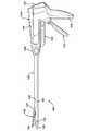
ここで、同一符号が同一要素を示す複数の図面を参照すると、この発明で使用されるように設計された外科用ステープラすなわちエンドカッタ100が図1に示されている。ステープラ100は、以前に組み込まれた特許文献1に記述された種類のものである。ステープラ100は、ハンドル部110と、回転手段120と、シャフト部130と、アンビル部140と、カートリッジアセンブリ150を含むものである。メス手段(図示せず)は、組織を切除するために、カートリッジアセンブリ150内に摺動可能である。ハンドル部110には、第1の、すなわち閉鎖トリガー(いわゆるクランプトリガー)112および第2の、すなわち加熱トリガー114が存在している。クランプトリガー112は、アンビル部140をカートリッジアセンブリ150に接近させる。加熱トリガー114は、ステープルを上記カートリッジから放出させかつ上記アンビル部140に対して形をなしている。また、加熱トリガー114は、組織を切除するために、上記カートリッジアセンブリ150を通じてメス手段を移動させる。 Referring now to the drawings, wherein like numerals indicate like elements, a surgical stapler or
この技術分野における当業者によって正当に評価されるように、以下に記述された外科用ステープルは、1985年6月4日にグリーン(Green)に発行され、参照することによってこの明細書に組み込まれた特許文献3に記述されているのと同様な開放式線形カッタの用途を有している。さらに、この明細書で使用されているように、ステープルは実質的に剛性であり変形可能な外科用ファスナのあらゆるタイプを言うものとする。したがって、この技術分野における当業者によって正当に評価されるように、以下に記述されるステープルは、ダビソン(Davison)らに発行され、参照することによってこの明細書に組み込まれた特許文献4に記述されたもののようなクリップ器具あるいは結紮装置に等しい用途を有している。 The surgical staples described below were issued to Green on June 4, 1985, and are incorporated herein by reference, as justified by those skilled in the art. It has the same use as an open linear cutter similar to that described in Japanese Patent Application Laid-Open No. H10-228707. Further, as used herein, staples shall refer to any type of surgical fastener that is substantially rigid and deformable. Accordingly, the staples described below are described in U.S. Patent No. 6,057,049 issued to Davison et al., Which is incorporated herein by reference, as would be appreciated by one of ordinary skill in the art. It has applications equivalent to clip devices or ligating devices such as
ここで、図2を参照すると、この実施の形態では、この発明に従って作製されかつカートリッジアセンブリ150として上述されたタイプのカートリッジに導入されるように設計されたステープル2として示された外科用ファスナが示されている。以下に述べられるように、ステープル2は、第1の未配置形状と、第2の配置形状を有している。図2は、第1の未配置形状をなすステープル2を描写している。ステープル2は、第1の端部6、第2の端部8および両端部間に延在する長軸9を有する冠部4を備えている。ステープル2は、第1の脚部10および第2の脚部20をも含む。両脚部10および20は、上記冠部4の第1の端部6および第2の端部8に取り付けられた第1の端部12および22を有している。両脚部10および20は、長軸9に対して概ね直交する方向に向けて冠部4から延在する第2の端部14および24をも有している。第2の端部14および24は鋭利な先端部16および18を含めてもよい。 Referring now to FIG. 2, in this embodiment, a surgical fastener shown as staple 2 made in accordance with the present invention and designed to be introduced into a cartridge of the type described above as
ステープル2の材料構成は、図3を参照することによって最もよく記述されることができる。図面から明らかなように、少なくとも両脚部は、仮にステープル全体でない場合に、同一の広がりをもち、互いに接合される3つの材料層30、40および50から構成されている。以下に詳述されるように、第1の材料層すなわちコア30は、実質的に上記ステープルの第2の形状に応力緩和される形状を有する超弾性合金から作成されている。第2の材料層40すなわち外殻は、実質的に上記ステープルの第1の形状に応力緩和される形状を有する線形弾性材料から作成されている。第2の材料層40は、上記ファスナが配置される前に、上記第1の未配置形状に上記第1の材料層を維持するのに十分な剛性を有している。第3の材料層50は、好ましくは、上記第1の材料層と上記第2の材料層との間で拡散するのを実質的に阻止する材料から作成されている。 The material configuration of the staple 2 can best be described by referring to FIG. As is apparent from the drawings, at least both legs are composed of three
この発明の目的のためには、第1の材料層および第2の材料層は、交換可能である。例えば、第1の内部層30すなわちコアは線形弾性材料から作成可能であるのに対して、第2の外部層40すなわち外郭は超弾性材料から構成されている。さらに、上記複数の材料層は断面円形状である必要がないが、あらゆる所望の形状をとることができる。さらに、上記ステープルの断面はコア/外郭の構成を有する必要がない。上記複数の材料層は、互いに並列されかつ同一の広がりを有することができるか、あるいはあらゆる他の所望の構成を有することができる。 For the purposes of this invention, the first material layer and the second material layer are interchangeable. For example, the first
第1の材料層30は、好ましくは、超弾性あるいは擬似弾性の合金から作成される。このようなタイプの材料の1つは、一般にニチノール(NITINOL)と呼ばれている。形状記憶合金の超弾性転移の性質は、非特許文献1において論じられている。上記非特許文献に開示された主題は、参照することによってこの明細書に組み込まれる。形状記憶合金の主な特性は、応力に伴う略直線的な歪みの初期増加を含むものである。この挙動は可逆的であり、従来の弾性変形に対応している。次の歪みは、「負荷安定状態」の終了時のレベルに限定された歪み範囲を越える、ほとんどないか、あるいは全くない応力の増加に伴って増加される。負荷安定状態の応力は、応力/歪みのグラフ上の変曲点によって定義される。無負荷ときには、応力が歪みの低下に伴ってほとんど変化しないグラフに沿う変曲点の存在によって証明された「無負荷安定状態」の開始時のレベルまで歪みを低下させることに伴う応力の低下が存在する。「無負荷安定状態」の終了時において、応力は、歪みの低下に伴って低下する。無負荷安定状態の応力も、応力/歪みのグラフ上の変曲点によって定義される。応力ゼロに負荷をなくした後に残るあらゆる歪みは、上記サンプルの永久固化である。この変形、負荷安定状態、無負荷安定状態、弾性計数、安定状態の長さおよび永久固化(特異的な全変形を基準にして定義された)の特性は設定され、例えば非特許文献1の376頁に定義されている。 The
非線形の超弾性特性は、上記合金を冷間加工する処理、例えばプレス成形、加圧成形あるいは絞り加工を含む処理によって形状記憶合金に導入可能である。上記超弾性特性は、第1の、すなわち配置/制約形状と、第2の、すなわち未配置/緩和形状との間でのステープルの形状変化によって使用される。適切な処理としては、冷間加工(例えば、加圧成形、絞り加工あるいは、特にマンドレル伸張)と、上記ステープルが上記冷間加工から得られる形状に制約されている一方で、上記合金の再結晶温度以下の温度での熱処理との組み合わせを挙げることができる。複数の冷間加工および熱処理ステップは使用可能である。上記ステープルは、その後、未配置形状に向けて変形可能であり、その変形は回復可能であり、実質的に弾性的である。この場合には、8%までの歪みからなる変形は、実質的に弾性的に付与かつ回復可能である。第1の材料層30用の合金は、好ましくは上記合金が体温で超弾性特性を示すように製造される。 Non-linear superelastic properties can be introduced into the shape memory alloy by a process of cold working the alloy, for example, a process including press forming, pressure forming or drawing. The superelastic properties are used by the change in the shape of the staples between the first, i.e. placed / constrained shape, and the second, i.e. unplaced / relaxed shape. Suitable treatments include cold working (eg, pressure forming, drawing or especially mandrel stretching) and recrystallization of the alloy while the staple is constrained to the shape obtained from the cold working. The combination with the heat processing at the temperature below temperature can be mentioned. Multiple cold working and heat treatment steps can be used. The staple can then be deformed towards an undeployed shape, the deformation being recoverable and substantially elastic. In this case, deformations consisting of up to 8% strain can be applied and recovered substantially elastically. The alloy for the
第1の材料層用である好ましくは、ニチノール(NITINOL)すなわちニッケル・チタン2成分系合金は、少なくとも約50原子%(以後、at.%という)、好ましくは50.5at.%のニッケル含有量を有している。ニッケル含有量は、通常、約54at.%以下、好ましくは約52at.%以下とされる。この技術分野における当業者によって正当に評価されるように、第1の材料層は、3成分系および4成分系を添加した合金を含む他のニッケル・チタン系合金から作成可能である。上記合金に組込み可能な元素例としては、鉄、コバルト、クロム、アルミニウム、銅およびバナジウムが挙げられる。添加される元素は、約10at.%まで、好ましくは約5at.%までの量で存在することができる。好ましくは、オーステナイト最終温度(Af)は体温以下、より好ましくは0℃前後である。 Preferably, NITINOL, a nickel-titanium binary alloy, for the first material layer is at least about 50 atomic% (hereinafter referred to as at.%), Preferably 50.5 at. % Nickel content. The nickel content is usually about 54 at. % Or less, preferably about 52 at. % Or less. The first material layer can be made from other nickel-titanium alloys, including alloys with addition of ternary and quaternary systems, as will be appreciated by those skilled in the art. Examples of elements that can be incorporated into the alloy include iron, cobalt, chromium, aluminum, copper and vanadium. The added element is about 10 at. %, Preferably about 5 at. It can be present in an amount up to%. Preferably, the austenite final temperature (Af) is below body temperature, more preferably around 0 ° C.
第2の材料層40は、好ましくは、鉄、非超弾性ニチノール(NITINOL)、ステンレス鋼あるいはチタン等の線形弾性材料から作成されている。第2の材料層は、ステープルがX線下でよく確認できるように、上記ステープルに対してX線不透過性品質を付与する材料から作成可能でもある。第2の材料層の耐力は、第1の材料層の回復強度より少し高くなるように設定されている。 The
第3の材料層50は、好ましくは、第1の材料層と第2の材料との間で拡散するのを実質的に阻止する材料から作成されている。第3の材料層50は、第1の材料あるいは第2の材料のいずれかと混合した際に、脆性合金あるいは金属間化合物を形成しない元素とすることができる。第3の材料層50は、好ましくは第1の材料層および第2の材料層の双方と強い結合を容易に形成し、かつ挿入された際に電気化学的腐食を誘導しないように、配置形状をなす第1の材料層および第2の材料層と電気化学的な適合性を有することが好ましい。さらに、第3の材料層50は、それ自体および第1の材料層および第2の材料層に結合した際に、生体適合性を有することが好ましい。 The
第1の材料層30がニチノール(NITINOL)から作成されかつ第2の材料層40がチタンから作成されたときには、第3の材料層50は、タンタルおよびニオブ等の材料から作成可能である。上記ワイヤを製造する際に、ニチノール(NITINOL)押出あるいはワイヤ絞り加工は好ましくは浄化して実施され、その後に第3の材料層50で被覆される。バリア被覆系ニチノール(NITINOL)コアは、ぴったり合った非常に清潔なチタン製カバー部品内に配置されることになる。周知の処置は、接合面から酸素、他の脆化ガスおよび元素を排除するのに使用することができ、かつこれら物質は熱的および機械的手段の組み合わせを使用して結合されることになる。 When the
第3の材料層50の厚さは多くの検討に基づいて設定可能である。仕上げられた複合ワイヤの最小厚は、上記ワイヤをステープルまたはクリップ様の部品内に組み入れると同時に行う初期加工およびその後の熱処理加工中にチタンからニチノール(NITINOL)を確実に分離することができる最も厚い材料層に基づいて設定可能である。バリアの最大厚は、最終形のファスナの機械特性に重要な影響を及ぼすことなく、その機械特性を示すことができるバリア元素の最大量に基づいて設定可能である。 The thickness of the
上記3つの材料から作成されたワイヤが形成された後に、そのワイヤはファスナの所望の長さを有するセグメントに切断可能である。セグメントは、上記ニチノール(NITINOL)が実質的にマルテンサイトであるように冷却した後に、上記セグメントは、図4に示された所望の第2/配置形状に変形される。上記セグメントは、その後にニチノール(NITINOL)の形状を固定し、部分的にチタンを応力緩和するために熱処理される。上記ワイヤ中のニチノール(NITINOL)が形状固定された後に、ステープルは図2に描写された幾何学的形状になるように直線化され、従来の外科用ステープル内に挿入されかつ使用されることになるステープル2を形成する。 After a wire made from the three materials is formed, the wire can be cut into segments having the desired length of the fastener. After the segment has cooled so that the NITINOL is substantially martensite, the segment is deformed to the desired second / arrangement configuration shown in FIG. The segments are then heat treated to fix the shape of NITINOL and partially stress relieve the titanium. After the NITINOL in the wire is fixed in shape, the staple is straightened to the geometric shape depicted in FIG. 2 and inserted into and used in a conventional surgical staple. A staple 2 is formed.
ステープル2は、それ自体が形状記憶合金の特性の一部と線形弾性材料の特性の一部を有するように、形状記憶合金および線形弾性材料を併用する。ステープルをカートリッジからアンビルに向けて放出するなど、上記ステープルを配置しているときには、印加応力と内部に発生する形状記憶の回復応力との和は、上記ステープルが変形することになるように線形弾性材料の耐力を上回る。上記負荷が形状固定材料の回復応力を支援するようにして印加される場合には、変形を生じさせるのに必要な外部負荷は、仮に上記力がステープルの線形弾性部分だけに印加された場合よりも小さくなるはずである。 The staple 2 uses a shape memory alloy and a linear elastic material together so that the staple 2 itself has a part of the characteristic of the shape memory alloy and a part of the characteristic of the linear elastic material. When the staple is placed, such as when the staple is released from the cartridge toward the anvil, the sum of the applied stress and the shape memory recovery stress generated therein is linearly elastic so that the staple deforms. Exceeds material strength. When the load is applied to support the recovery stress of the shape-fixing material, the external load required to cause the deformation is less than if the force was applied only to the linear elastic portion of the staple. Should be smaller.
上記ステープルが配置されたときには、ステープルは変形を開始し、従来のステープルよりも非常に小さな負荷で所望のB字状を呈することになる。これは、ステープルの形成初期段階でも、上記ステープルの先端部はフック状をなし、最終的には図4に示されているように、ステープル上に曲げ戻されることを意味する。これとは対照的に、従来のステープルは、その中間部分が初期段階で座屈し、ステープルの遠位部分の大部分は直線状のままで、曲げられもしない。結果として、従来のステープルが非常に薄い組織に最も大きく変形した場合には、ステープル脚部の直線部分はステープルの平坦な基部を越えて通過し、そのステープル先端部は組織を捉えかつ傷つけることが可能な状態で、上記組織から突き出てしまう。仮に、組織が非常に厚く、かつステープル脚部の遠位部分のみが形成されている場合には、上記ステープル脚部はそれ自体の上に戻るように曲線化せず、上記組織を所定の位置に保持するのに必要なフック状の幾何学的形状を形成しないことになる。上述したステープルおよびこれに関連した幾何学的形状は従来の欠点を低減するものである。 When the staples are placed, the staples start to deform and exhibit a desired B-shape with a much smaller load than conventional staples. This means that even at the initial stage of staple formation, the leading end portion of the staple has a hook shape and is finally bent back on the staple as shown in FIG. In contrast, conventional staples buckle at an early stage in the middle, and most of the distal portion of the staple remains straight and is not bent. As a result, when a conventional staple is most deformed into a very thin tissue, the straight portion of the staple leg passes past the flat base of the staple and the staple tip can catch and damage the tissue. If possible, it will stick out of the tissue. If the tissue is very thick and only the distal portion of the staple leg is formed, the staple leg will not curve back on itself, causing the tissue to be in place. The hook-like geometric shape necessary for holding is not formed. The staples described above and the associated geometry reduce conventional disadvantages.
放射状の成形力は、薄い組織内でも、ステープラが打撃を与えて上記ステープルを形成する場合よりも僅かに低い高さで、当初形成されかつ形状固定された上記ステープルを与える成形処理の全体にわたって、上述したステープルに対してより小さく残ることになる。このステープル成形力における基本的な低減は、上記アンビルおよびカートリッジのチャンネル分離を強制する傾向が低減されることから、機器全体への波及効果を有することになる。同様に、光源部品はステープル線とステープル線長との所定の組み合わせに使用可能である。さらに、上記部品は、上記部品を不快な大きな塊にさせることなく、現に実行可能なものより長いステープル線長を有する片持ち梁式の顎ステープラ(最も一般的な構成)を設計するのを実行可能にさせる。 Radial forming force is applied throughout the forming process to provide the initially formed and fixed shape staple, even in thin tissue, at a slightly lower height than when the stapler strikes to form the staple. It will remain smaller than the staples described above. This fundamental reduction in staple forming force will have a ripple effect on the entire instrument as the tendency to force channel separation of the anvil and cartridge is reduced. Similarly, the light source component can be used for a predetermined combination of staple line and staple line length. In addition, the part is designed to design a cantilever jaw stapler (the most common configuration) with a longer staple line length than is actually feasible without making the part into an unpleasant large mass. Make it possible.
上述したステープルの特性は、片手による圧搾動作を用いる人間によって形成可能なステープル数、その結果としてステープル線長を製造者に増加させることができる。これは、より小さなステープラにおける経済的で人気の一握り、片手による加熱機構が、より長いステープル線を有するステープラで使用可能であることを意味する。これは、全てのステープルを形成するために、あるいは使用時に、外科医の触知可能なフィードバックを拒む有力な設計を当てにする複数の操作を必要とするステープラのコストおよび複雑性について明白な利点を与えることになる。 The staple characteristics described above allow the manufacturer to increase the number of staples that can be formed by a human using a one-handed squeezing action, and consequently the staple line length. This means that a handful of economics and popularity in smaller staplers, a one-handed heating mechanism can be used in staplers with longer staple lines. This has the obvious advantage of the cost and complexity of a stapler that requires multiple operations to form all the staples or rely on a powerful design that, in use, rejects the surgeon's tangible feedback. Will give.
この発明の好適な実施の形態がこの明細書に図示されかつ記述されたが、上記実施の形態は単に例示として与えられていることは、この技術分野における当業者にとって明白なはずである。多くの変化、変更および置換は、この発明から逸脱することなく、この技術分野における当業者によって検討されることになる。例えば、この技術分野における当業者にとって明白なように、この明細書に開示された内容は、ロボット支援外科術における等しい用途を有している。さらに、上述したあらゆる構造が1つの機能を有し、そのような構造が上記機能を実行する手段として参照できることは理解されるべきである。したがって、この発明が添付した請求項の精神および範囲のみによって限定されるものと意図されている。 While preferred embodiments of the present invention have been illustrated and described herein, it should be apparent to those skilled in the art that the above embodiments are provided by way of example only. Many variations, modifications and substitutions will be considered by those skilled in the art without departing from the invention. For example, as will be apparent to those skilled in the art, the content disclosed herein has equal use in robot-assisted surgery. Furthermore, it should be understood that every structure described above has a function and such structure can be referred to as a means for performing the function. Accordingly, it is intended that this invention be limited only by the spirit and scope of the appended claims.
この発明の具体的な実施態様は以下の通りである。
(1)器具に導入するための第1の未配置形状と、組織を互いに連結するための第2の配置形状を有する医療用ファスナであって、a.両端部を有する冠部と、第1および第2の脚部を含み、これら脚部の一方が上記冠部の各端部に取り付けられており、上記両脚部は、上記ファスナが上記第1の未配置形状にあるときに、互いに分離されており、b.上記両脚部は、一緒に接合される材料からなる第1、第2および第3の材料層を含み、上記第1の材料層は、実質的に上記第2の配置形状に応力緩和される形状を有する超弾性合金を含み、上記第2の材料層は、実質的に上記第1の未配置形状に応力緩和される形状を有すると共に、上記ファスナが配置される前に、上記第1の未配置形状に上記第1の材料層を維持するのに十分な剛性を有する線形弾性材料を含み、上記第3の材料層が上記第1の材料層と上記第2の材料層との間に配置されかつ上記第1の材料層と上記第2の材料層の間で拡散するのを実質的に阻止する材料を含む、ファスナ。
(2)上記第2の材料層は、次の材料:鉄、非超弾性ニッケル・チタン合金、ステンレス鋼、チタンのうち、少なくとも1つから選択される材料を含む、実施態様1記載のファスナ。
(3)上記第3の材料層は、次の材料:タンタルおよびニオブのうち少なくとも1つから選択される材料を含む、実施態様1記載のファスナ。
(4)上記第1の材料層は、ニッケル・チタン合金を含む、実施態様1記載のファスナ。
(5)上記第1の材料層は、37℃以下のオーステナイト最終温度を有している、実施態様4記載のファスナ。Specific embodiments of the present invention are as follows.
(1) A medical fastener having a first undeployed shape for introduction into an instrument and a second deployed shape for connecting tissues together, comprising: a. A crown having opposite ends, and first and second legs, one of the legs being attached to each end of the crown, the legs having the fastener being the first Separated from each other when in an unplaced shape; b. The both leg portions include first, second and third material layers made of materials to be joined together, and the first material layer has a shape that is substantially stress relieved to the second arrangement shape. The second material layer has a shape that is substantially stress relieved to the first unplaced shape, and before the fastener is disposed, A linear elastic material having sufficient rigidity to maintain the first material layer in a deployed configuration, wherein the third material layer is disposed between the first material layer and the second material layer; And a fastener comprising a material that substantially prevents diffusion between the first material layer and the second material layer.
(2) The fastener according to embodiment 1, wherein the second material layer includes a material selected from at least one of the following materials: iron, non-superelastic nickel / titanium alloy, stainless steel, and titanium.
(3) The fastener according to embodiment 1, wherein the third material layer includes a material selected from at least one of the following materials: tantalum and niobium.
(4) The fastener according to embodiment 1, wherein the first material layer includes a nickel-titanium alloy.
(5) The fastener according to embodiment 4, wherein the first material layer has an austenite final temperature of 37 ° C or lower.
(6)上記第1の材料層は、0℃以下のオーステナイト最終温度を有している、実施態様4記載のファスナ。
(7)上記第2の材料層は、上記第1の材料層の周囲に同心円状に配されている、実施態様4記載のファスナ。
(8)上記両脚部は、実質的に円形状を有している、実施態様7記載のファスナ。
(9)上記第2の形状は、実質的にB字状である、実施態様1記載のファスナ。
(10)上記ファスナはステープルである、実施態様1記載のファスナ。(6) The fastener according to embodiment 4, wherein the first material layer has an austenite final temperature of 0 ° C. or lower.
(7) The fastener according to embodiment 4, wherein the second material layer is arranged concentrically around the first material layer.
(8) The fastener according to embodiment 7, wherein the both legs have a substantially circular shape.
(9) The fastener according to embodiment 1, wherein the second shape is substantially B-shaped.
(10) The fastener according to embodiment 1, wherein the fastener is a staple.
(11)器具に導入するための第1の未配置形状と、組織を互いに連結するための第2の配置形状を有する医療用ファスナであって、a.両端部を有する冠部と、第1および第2の脚部を含み、これら脚部の一方が上記冠部の各端部に取り付けられており、上記両脚部は、上記ファスナが上記第1の未配置形状にあるときに、互いに分離されており、b.上記両脚部は、一緒に接合される材料からなる第1、第2および第3の材料層を含み、上記第1の材料層は、実質的に上記第2の配置形状に応力緩和される形状を有する超弾性合金を含み、上記第2の材料層は、実質的に上記第1の未配置形状に応力緩和される形状を有すると共に、上記ファスナが配置される前に、上記第1の未配置形状に上記第1の材料層を維持するのに十分な剛性を有するチタンを含み、上記第3の材料層が上記第1の材料層と上記第2の材料層との間に配置されかつ上記第1の材料層と上記第2の材料層の間で拡散するのを実質的に阻止する材料を含む、ファスナ。
(12)上記第3の材料層は、次の材料:タンタルおよびニオブのうち少なくとも1つから選択される材料を含む、実施態様11記載のファスナ。
(13)上記第1の材料層は、37℃以下のオーステナイト最終温度を有している、実施態様11記載のファスナ。
(14)上記第1の材料層は、0℃以下のオーステナイト最終温度を有している、実施態様11記載のファスナ。
(15)上記第2の材料層は、上記第1の材料層の周囲に同心円状に配されている、実施態様11記載のファスナ。(11) A medical fastener having a first unplaced shape for introduction into the instrument and a second placed shape for connecting tissues together, comprising: a. A crown having opposite ends, and first and second legs, one of the legs being attached to each end of the crown, the legs having the fastener being the first Separated from each other when in an unplaced shape; b. The legs include first, second and third material layers made of materials to be joined together, and the first material layer has a shape that is substantially stress relieved to the second arrangement shape. The second material layer has a shape that is substantially stress relieved to the first non-arranged shape, and before the fastener is disposed, Including titanium having sufficient rigidity to maintain the first material layer in a deployed configuration, wherein the third material layer is disposed between the first material layer and the second material layer; A fastener comprising a material that substantially prevents diffusion between the first material layer and the second material layer.
(12) The fastener according to embodiment 11, wherein the third material layer includes a material selected from at least one of the following materials: tantalum and niobium.
(13) The fastener according to embodiment 11, wherein the first material layer has an austenite final temperature of 37 ° C or lower.
(14) The fastener according to embodiment 11, wherein the first material layer has an austenite final temperature of 0 ° C. or less.
(15) The fastener according to embodiment 11, wherein the second material layer is arranged concentrically around the first material layer.
(16)上記両脚部は、実質的に円形状を有している、実施態様11記載のファスナ。
(17)上記第2の形状は、実質的にB字状である、実施態様11記載のファスナ。
(18)上記ファスナはステープルである、実施態様11記載のファスナ。(16) The fastener according to embodiment 11, wherein the both legs have a substantially circular shape.
(17) The fastener according to embodiment 11, wherein the second shape is substantially B-shaped.
(18) A fastener according to embodiment 11, wherein the fastener is a staple.
2 ステープル
4 冠部
6 第1の端部
8 第2の端部
9 長軸
10 脚部
12 第1の端部
14 第2の端部
16 鋭利な先端部
18 鋭利な先端部
20 脚部
22 第1の端部
24 第2の端部
30 第1の材料層
40 第2の材料層
50 第3の材料層
100 外科用ステープラ、エンドカッタ
110 ハンドル部
112 閉鎖トリガー、クランプトリガー
114 加熱トリガー
120 回転手段
130 シャフト部
140 アンビル部
150 カートリッジアセンブリ
2 Staple 4
Claims (11)
Translated fromJapaneseA medical fastener having a first undeployed shape for introduction into the instrument and a second deployed shape for connecting tissue together, comprising: a. A crown having opposite ends, and first and second legs, one of the legs being attached to each end of the crown, the legs having the fastener being the first Separated from each other when in an unplaced shape; b. The legs include first, second and third material layers made of materials to be joined together, and the first material layer has a shape that is substantially stress relieved to the second arrangement shape. The second material layer has a shape that is substantially stress relieved to the first non-arranged shape, and before the fastener is disposed, Including titanium having sufficient rigidity to maintain the first material layer in a deployed configuration, wherein the third material layer is disposed between the first material layer and the second material layer; A fastener comprising a material that substantially prevents diffusion between the first material layer and the second material layer.
Applications Claiming Priority (1)
| Application Number | Priority Date | Filing Date | Title |
|---|---|---|---|
| US10/870,348US20050283190A1 (en) | 2004-06-16 | 2004-06-16 | Surgical fastener |
Publications (1)
| Publication Number | Publication Date |
|---|---|
| JP2006000651Atrue JP2006000651A (en) | 2006-01-05 |
Family
ID=34941687
Family Applications (1)
| Application Number | Title | Priority Date | Filing Date |
|---|---|---|---|
| JP2005175483APendingJP2006000651A (en) | 2004-06-16 | 2005-06-15 | Improved surgical fastener |
Country Status (12)
| Country | Link |
|---|---|
| US (1) | US20050283190A1 (en) |
| EP (1) | EP1607048B1 (en) |
| JP (1) | JP2006000651A (en) |
| KR (1) | KR20060049605A (en) |
| CN (1) | CN1711970A (en) |
| AT (1) | ATE460888T1 (en) |
| AU (1) | AU2005202185A1 (en) |
| BR (1) | BRPI0502373A (en) |
| CA (1) | CA2509610A1 (en) |
| DE (1) | DE602005019947D1 (en) |
| MX (1) | MXPA05006412A (en) |
| RU (1) | RU2005118634A (en) |
Families Citing this family (61)
| Publication number | Priority date | Publication date | Assignee | Title |
|---|---|---|---|---|
| US7896222B2 (en)* | 2004-10-01 | 2011-03-01 | Regents Of The University Of Michigan | Manufacture of shape memory alloy cellular materials and structures by transient-liquid reactive joining |
| CN101170966A (en) | 2005-04-01 | 2008-04-30 | 科罗拉多州立大学董事会 | Graft fixation devices and methods |
| US8342376B2 (en)* | 2005-06-10 | 2013-01-01 | Cook Medical Technologies Llc | Medical stapler |
| WO2008097999A2 (en) | 2007-02-05 | 2008-08-14 | Mitralsolutions, Inc. | Minimally invasive system for delivering and securing an annular implant |
| US20100069928A1 (en)* | 2007-03-12 | 2010-03-18 | Alberto Bauer | Anchor, system and method to attach a human tissue or suture to a bone |
| US8979872B2 (en)* | 2007-03-13 | 2015-03-17 | Longevity Surgical, Inc. | Devices for engaging, approximating and fastening tissue |
| US9636111B2 (en) | 2007-05-07 | 2017-05-02 | Covidien Lp | Method of stapling tissues with a staple assembly |
| US8348972B2 (en) | 2007-07-11 | 2013-01-08 | Covidien Lp | Surgical staple with augmented compression area |
| WO2009029065A1 (en)* | 2007-08-24 | 2009-03-05 | Hazem Ezzat | A surgical device and method |
| US20140012316A1 (en)* | 2007-12-03 | 2014-01-09 | Howard D. Stupak | Wound closure involving silicone |
| US9375287B2 (en) | 2008-01-29 | 2016-06-28 | Covidien Lp | Target identification tool for intra-body localization |
| US9301826B2 (en) | 2008-02-18 | 2016-04-05 | Covidien Lp | Lock bar spring and clip for implant deployment device |
| US9034002B2 (en) | 2008-02-18 | 2015-05-19 | Covidien Lp | Lock bar spring and clip for implant deployment device |
| US9044235B2 (en) | 2008-02-18 | 2015-06-02 | Covidien Lp | Magnetic clip for implant deployment device |
| US8808314B2 (en) | 2008-02-18 | 2014-08-19 | Covidien Lp | Device and method for deploying and attaching an implant to a biological tissue |
| WO2009104182A2 (en) | 2008-02-18 | 2009-08-27 | Polytouch Medical Ltd | A device and method for deploying and attaching a patch to a biological tissue |
| US8758373B2 (en) | 2008-02-18 | 2014-06-24 | Covidien Lp | Means and method for reversibly connecting a patch to a patch deployment device |
| US9393093B2 (en) | 2008-02-18 | 2016-07-19 | Covidien Lp | Clip for implant deployment device |
| US9393002B2 (en) | 2008-02-18 | 2016-07-19 | Covidien Lp | Clip for implant deployment device |
| US9398944B2 (en) | 2008-02-18 | 2016-07-26 | Covidien Lp | Lock bar spring and clip for implant deployment device |
| US9833240B2 (en) | 2008-02-18 | 2017-12-05 | Covidien Lp | Lock bar spring and clip for implant deployment device |
| US8317808B2 (en) | 2008-02-18 | 2012-11-27 | Covidien Lp | Device and method for rolling and inserting a prosthetic patch into a body cavity |
| US8231041B2 (en) | 2008-04-14 | 2012-07-31 | Tyco Healthcare Group Lp | Variable compression surgical fastener cartridge |
| US8100310B2 (en) | 2008-04-14 | 2012-01-24 | Tyco Healthcare Group Lp | Variable compression surgical fastener apparatus |
| US8231040B2 (en) | 2008-04-14 | 2012-07-31 | Tyco Healthcare Group Lp | Variable compression surgical fastener cartridge |
| US7926691B2 (en) | 2008-04-14 | 2011-04-19 | Tyco Healthcare Group, L.P. | Variable compression surgical fastener cartridge |
| WO2009130631A2 (en)* | 2008-04-21 | 2009-10-29 | Simcha Milo | Surgical stapling systems |
| US8967446B2 (en) | 2008-05-09 | 2015-03-03 | Covidien Lp | Variable compression surgical fastener cartridge |
| US8186556B2 (en) | 2008-05-09 | 2012-05-29 | Tyco Healthcare Group Lp | Variable compression surgical fastener apparatus |
| US8091756B2 (en) | 2008-05-09 | 2012-01-10 | Tyco Healthcare Group Lp | Varying tissue compression using take-up component |
| US8464922B2 (en) | 2008-05-09 | 2013-06-18 | Covidien Lp | Variable compression surgical fastener cartridge |
| US20100023052A1 (en) | 2008-07-23 | 2010-01-28 | Tyco Healthcare Group Lp | Staple for use in surgical procedures |
| EP2317937B1 (en)* | 2008-07-24 | 2021-01-13 | CONMED Corporation | Medical device comprising a shape memory polymer |
| US8430933B2 (en) | 2008-07-24 | 2013-04-30 | MedShape Inc. | Method and apparatus for deploying a shape memory polymer |
| US8069858B2 (en) | 2008-07-24 | 2011-12-06 | Medshape Solutions, Inc. | Method and apparatus for deploying a shape memory polymer |
| EP2337502B1 (en) | 2008-10-20 | 2014-08-06 | Covidien LP | A device for attaching a patch to a biological tissue |
| JP2012531240A (en) | 2009-06-26 | 2012-12-10 | クイックリング メディカル テクノロジーズ リミテッド | Surgical stapler and method of surgical stapling |
| WO2011021082A1 (en) | 2009-08-17 | 2011-02-24 | PolyTouch Medical, Inc. | Means and method for reversibly connecting an implant to a deployment device |
| US8906045B2 (en) | 2009-08-17 | 2014-12-09 | Covidien Lp | Articulating patch deployment device and method of use |
| WO2012019052A2 (en) | 2010-08-04 | 2012-02-09 | Micardia Corporation | Percutaneous transcatheter repair of heart valves |
| US9427493B2 (en) | 2011-03-07 | 2016-08-30 | The Regents Of The University Of Colorado | Shape memory polymer intraocular lenses |
| US9402721B2 (en) | 2011-06-01 | 2016-08-02 | Valcare, Inc. | Percutaneous transcatheter repair of heart valves via trans-apical access |
| WO2013130641A1 (en) | 2012-02-29 | 2013-09-06 | Valcare, Inc. | Percutaneous annuloplasty system with anterior-posterior adjustment |
| US9180008B2 (en) | 2012-02-29 | 2015-11-10 | Valcare, Inc. | Methods, devices, and systems for percutaneously anchoring annuloplasty rings |
| US8808385B1 (en) | 2013-01-06 | 2014-08-19 | Medshape, Inc. | Mechanically-activated shape memory polymer spinal cage |
| US10166100B2 (en) | 2013-03-15 | 2019-01-01 | Valcare, Inc. | Systems and methods for delivery of annuloplasty rings |
| US10813751B2 (en) | 2013-05-22 | 2020-10-27 | Valcare, Inc. | Transcatheter prosthetic valve for mitral or tricuspid valve replacement |
| US20160120642A1 (en) | 2013-05-24 | 2016-05-05 | Valcare, Inc. | Heart and peripheral vascular valve replacement in conjunction with a support ring |
| US11058417B2 (en) | 2013-06-28 | 2021-07-13 | Valcare, Inc. | Device, system, and method to secure an article to a tissue |
| US10524912B2 (en)* | 2015-04-02 | 2020-01-07 | Abbott Cardiovascular Systems, Inc. | Tissue fixation devices and methods |
| CN107753153B (en) | 2016-08-15 | 2022-05-31 | 沃卡尔有限公司 | Device and method for treating heart valve insufficiency |
| US10555734B2 (en)* | 2017-02-17 | 2020-02-11 | Ethicon Llc | Methods and systems for mating constrictable adjunct materials with end effectors |
| CN108618871A (en) | 2017-03-17 | 2018-10-09 | 沃卡尔有限公司 | Bicuspid valve with multi-direction anchor portion or tricuspid valve repair system |
| CN108194773B (en)* | 2018-01-31 | 2024-06-07 | 扬州海通电子科技有限公司 | Adjustable nonlinear elastic supporting wheel device |
| US11534300B2 (en) | 2018-12-03 | 2022-12-27 | Valcare, Inc. | Stabilizing and adjusting tool for controlling a minimally invasive mitral / tricuspid valve repair system |
| US11376000B2 (en)* | 2019-03-13 | 2022-07-05 | Covidien Lp | Surgical stapler anvil with directionally biased staple pockets |
| EP3982881B1 (en) | 2019-06-11 | 2025-04-16 | Valcare Medical, Inc. | Annuloplasty ring with posterior leaflet for minimally invasive treatment |
| US12396853B2 (en) | 2019-06-11 | 2025-08-26 | Valcare Medical, Inc. | Systems and methods for delivery of chordae replacement system |
| US11793628B2 (en) | 2019-07-15 | 2023-10-24 | Valcare, Inc. | Transcatheter bio-prosthesis member and support structure |
| CN111227916B (en)* | 2020-01-17 | 2021-02-05 | 郑州大学第一附属医院 | Degradable flexibly connected U-shaped bone nail with muscle and bone inducing activity |
| US20220354487A1 (en)* | 2021-05-10 | 2022-11-10 | Cilag Gmbh International | Method for implementing a staple system |
Citations (2)
| Publication number | Priority date | Publication date | Assignee | Title |
|---|---|---|---|---|
| US6387121B1 (en)* | 1996-10-21 | 2002-05-14 | Inflow Dynamics Inc. | Vascular and endoluminal stents with improved coatings |
| US6638297B1 (en)* | 2002-05-30 | 2003-10-28 | Ethicon Endo-Surgery, Inc. | Surgical staple |
Family Cites Families (9)
| Publication number | Priority date | Publication date | Assignee | Title |
|---|---|---|---|---|
| AU534210B2 (en) | 1980-02-05 | 1984-01-12 | United States Surgical Corporation | Surgical staples |
| US5350400A (en)* | 1991-10-30 | 1994-09-27 | American Cyanamid Company | Malleable, bioabsorbable, plastic staple; and method and apparatus for deforming such staple |
| GR1002336B (en) | 1992-05-06 | 1996-05-21 | Ethicon Inc. | Endoscopic surgical apparatus capable of ligation and division. |
| US5632432A (en) | 1994-12-19 | 1997-05-27 | Ethicon Endo-Surgery, Inc. | Surgical instrument |
| US5611874A (en)* | 1995-07-26 | 1997-03-18 | Surface Genesis, Inc. | Clad shape memory alloy composite structure and method |
| FR2797275B1 (en)* | 1999-08-04 | 2001-11-23 | Mat Inov | METHOD FOR STORING TWO GEOMETRIC STATES OF A PRODUCT MADE IN A SHAPE MEMORY ALLOY AND APPLICATIONS OF THIS PROCESS TO PRODUCTS IN THE MEDICAL, DENTAL, VETERINARY OR OTHER AREAS |
| TW511246B (en)* | 2001-12-28 | 2002-11-21 | Nanya Technology Corp | Fuse structure |
| US20030225423A1 (en)* | 2002-05-30 | 2003-12-04 | Huitema Thomas W. | Surgical clip |
| US6866730B2 (en)* | 2003-03-21 | 2005-03-15 | General Motors Corporation | Metallic-based adhesion materials |
- 2004
- 2004-06-16USUS10/870,348patent/US20050283190A1/ennot_activeAbandoned
- 2005
- 2005-05-19AUAU2005202185Apatent/AU2005202185A1/ennot_activeAbandoned
- 2005-06-09CACA002509610Apatent/CA2509610A1/ennot_activeAbandoned
- 2005-06-15JPJP2005175483Apatent/JP2006000651A/enactivePending
- 2005-06-15EPEP05253693Apatent/EP1607048B1/ennot_activeCeased
- 2005-06-15BRBR0502373-4Apatent/BRPI0502373A/ennot_activeIP Right Cessation
- 2005-06-15KRKR1020050051442Apatent/KR20060049605A/ennot_activeWithdrawn
- 2005-06-15RURU2005118634/14Apatent/RU2005118634A/ennot_activeApplication Discontinuation
- 2005-06-15ATAT05253693Tpatent/ATE460888T1/ennot_activeIP Right Cessation
- 2005-06-15MXMXPA05006412Apatent/MXPA05006412A/enunknown
- 2005-06-15DEDE602005019947Tpatent/DE602005019947D1/ennot_activeExpired - Lifetime
- 2005-06-16CNCNA2005100772099Apatent/CN1711970A/enactivePending
Patent Citations (2)
| Publication number | Priority date | Publication date | Assignee | Title |
|---|---|---|---|---|
| US6387121B1 (en)* | 1996-10-21 | 2002-05-14 | Inflow Dynamics Inc. | Vascular and endoluminal stents with improved coatings |
| US6638297B1 (en)* | 2002-05-30 | 2003-10-28 | Ethicon Endo-Surgery, Inc. | Surgical staple |
Also Published As
| Publication number | Publication date |
|---|---|
| AU2005202185A1 (en) | 2006-01-12 |
| RU2005118634A (en) | 2006-12-20 |
| CN1711970A (en) | 2005-12-28 |
| EP1607048A1 (en) | 2005-12-21 |
| CA2509610A1 (en) | 2005-12-16 |
| EP1607048B1 (en) | 2010-03-17 |
| BRPI0502373A (en) | 2006-02-07 |
| MXPA05006412A (en) | 2006-01-31 |
| ATE460888T1 (en) | 2010-04-15 |
| KR20060049605A (en) | 2006-05-19 |
| US20050283190A1 (en) | 2005-12-22 |
| DE602005019947D1 (en) | 2010-04-29 |
Similar Documents
| Publication | Publication Date | Title |
|---|---|---|
| JP2006000651A (en) | Improved surgical fastener | |
| US6638297B1 (en) | Surgical staple | |
| CA2468227C (en) | Surgical clip | |
| JP5013489B2 (en) | Medical stapler | |
| US10687822B2 (en) | Thickness-adjustable hemostatic clips, clip appliers, and applications thereof | |
| JP4979972B2 (en) | Surgical clip | |
| US6726696B1 (en) | Patches and collars for medical applications and methods of use | |
| EP2389878A1 (en) | Surgical hemostatic clip including work-hardened, movement-inhibiting structure | |
| US20040087987A1 (en) | Non-invasive surgical ligation clip system and method of using | |
| CN113473919A (en) | Systems, devices, and methods for preparing highly elastic suture needles for minimally invasive surgery |
Legal Events
| Date | Code | Title | Description |
|---|---|---|---|
| RD04 | Notification of resignation of power of attorney | Free format text:JAPANESE INTERMEDIATE CODE: A7424 Effective date:20071129 | |
| A621 | Written request for application examination | Free format text:JAPANESE INTERMEDIATE CODE: A621 Effective date:20080613 | |
| RD04 | Notification of resignation of power of attorney | Free format text:JAPANESE INTERMEDIATE CODE: A7424 Effective date:20080922 | |
| A131 | Notification of reasons for refusal | Free format text:JAPANESE INTERMEDIATE CODE: A131 Effective date:20110111 | |
| A977 | Report on retrieval | Free format text:JAPANESE INTERMEDIATE CODE: A971007 Effective date:20110113 | |
| A02 | Decision of refusal | Free format text:JAPANESE INTERMEDIATE CODE: A02 Effective date:20110705 |