JP2006000201A - Ultrasonic probe and ultrasonic imaging device - Google Patents
Ultrasonic probe and ultrasonic imaging deviceDownload PDFInfo
- Publication number
- JP2006000201A JP2006000201AJP2004177092AJP2004177092AJP2006000201AJP 2006000201 AJP2006000201 AJP 2006000201AJP 2004177092 AJP2004177092 AJP 2004177092AJP 2004177092 AJP2004177092 AJP 2004177092AJP 2006000201 AJP2006000201 AJP 2006000201A
- Authority
- JP
- Japan
- Prior art keywords
- ultrasonic probe
- ultrasonic
- probe
- rotating
- levers
- Prior art date
- Legal status (The legal status is an assumption and is not a legal conclusion. Google has not performed a legal analysis and makes no representation as to the accuracy of the status listed.)
- Pending
Links
- 239000000523sampleSubstances0.000titleclaimsabstractdescription75
- 238000003384imaging methodMethods0.000titleclaimsdescription19
- 238000003780insertionMethods0.000claimsabstractdescription24
- 230000037431insertionEffects0.000claimsabstractdescription24
- 238000005452bendingMethods0.000claimsdescription34
- 230000007246mechanismEffects0.000claimsdescription9
- 230000005540biological transmissionEffects0.000claimsdescription5
- 238000006243chemical reactionMethods0.000claimsdescription3
- 238000004804windingMethods0.000description21
- 238000001574biopsyMethods0.000description3
- 238000010586diagramMethods0.000description3
- 210000003811fingerAnatomy0.000description3
- 210000000056organAnatomy0.000description3
- 210000003813thumbAnatomy0.000description3
- 239000000463materialSubstances0.000description2
- 229930182556PolyacetalNatural products0.000description1
- 210000000683abdominal cavityAnatomy0.000description1
- 230000003321amplificationEffects0.000description1
- 230000017531blood circulationEffects0.000description1
- 238000005219brazingMethods0.000description1
- 238000009940knittingMethods0.000description1
- 239000010687lubricating oilSubstances0.000description1
- 238000003199nucleic acid amplification methodMethods0.000description1
- 239000003921oilSubstances0.000description1
- 238000005192partitionMethods0.000description1
- 230000002093peripheral effectEffects0.000description1
- 229920006324polyoxymethylenePolymers0.000description1
- 239000011347resinSubstances0.000description1
- 229920005989resinPolymers0.000description1
- 229910001220stainless steelInorganic materials0.000description1
Images


Landscapes
- Ultra Sonic Daignosis Equipment (AREA)
Abstract
Description
Translated fromJapanese本発明は、超音波プローブに係り、体内に挿入するのに好適な超音波プローブに関する。 The present invention relates to an ultrasonic probe, and more particularly to an ultrasonic probe suitable for insertion into a body.
超音波撮像装置に用いられる超音波プローブは、探触子を介して撮像部位に超音波を射出すると共に、撮像部位から発生する超音波を反射エコー信号として受波する。そして、超音波プローブから出力される反射エコー信号に基づいて、超音波撮像装置により超音波像(例えば、断層像)を再構成して表示する。 An ultrasonic probe used in an ultrasonic imaging apparatus emits ultrasonic waves to an imaging region via a probe and receives ultrasonic waves generated from the imaging region as a reflected echo signal. Then, based on the reflected echo signal output from the ultrasonic probe, an ultrasonic image (for example, a tomographic image) is reconstructed and displayed by the ultrasonic imaging apparatus.
この超音波プローブとして、被検体に挿入した管(例えば、トラカール)を介して体内に先端を挿入して撮像するものが知られている。このような超音波プローブは、例えば、中空筒状の挿入部と、挿入部の一端に連接された中空の把持部と、挿入部の先端に可撓継手を介して連結された湾曲部と、湾曲部の先端に取り付けられた探触子を有して構成される。そして、湾曲部にワイヤを介して連結された操作レバーを操作することにより、湾曲部を直交2方向に屈曲させて探触子の超音波射出面を撮像部位(例えば、臓器)の表面に接触または近接させて撮像することが行われる(例えば、特許文献1)。 As this ultrasonic probe, an image obtained by inserting a distal end into a body through a tube (for example, trocar) inserted into a subject and imaging is known. Such an ultrasonic probe includes, for example, a hollow cylindrical insertion portion, a hollow gripping portion connected to one end of the insertion portion, a bending portion connected to the distal end of the insertion portion via a flexible joint, It has a probe attached to the tip of the bending portion. Then, by operating an operation lever connected to the bending portion via a wire, the bending portion is bent in two orthogonal directions, and the ultrasonic emission surface of the probe is brought into contact with the surface of the imaging region (for example, an organ). Alternatively, imaging is performed in close proximity (for example, Patent Document 1).
ところで、特許文献1のような超音波プローブにより取得した超音波像を参照しながら、特殊な器具を用いた他の作業を同時に行う場合がある。例えば、表示された超音波像を見ながら、体内にトラカールを介して生検針を体腔内等に刺入することで撮像部位の組織を採取することが行われる。その場合、操作者は、超音波プローブを片手で操作しながら、他方の手で特殊器具を操作することになるため、超音波プローブの片手での使い勝手を一層向上させることが要望される。 By the way, while referring to an ultrasonic image acquired by an ultrasonic probe as in Patent Document 1, other work using a special instrument may be performed simultaneously. For example, the tissue of the imaging region is collected by inserting a biopsy needle into a body cavity or the like through a trocar while viewing the displayed ultrasonic image. In this case, the operator operates a special instrument with the other hand while operating the ultrasonic probe with one hand, so that it is desired to further improve the usability of the ultrasonic probe with one hand.
本発明の課題は、超音波プローブの片手での使い勝手を一層向上させることにある。 An object of the present invention is to further improve the usability of an ultrasonic probe with one hand.
上記課題を解決するため、本発明の超音波プローブは、中空筒状の挿入部と、挿入部の一端に連接された中空の把持部と、挿入部の先端に可撓継手を介して連結された湾曲部と、湾曲部の先端に取り付けられた探触子と、把持部の内部に挿入部の軸に直交させて設けられたシャフトと、シャフトにそれぞれ回転自由に設けられた第1と第2の回転部材と、第1と第2の回転部材の挿入部の軸を挟んだ二箇所にそれぞれ接続されると共に湾曲部の内面の周方向に間隔をあけて固定された2組のワイヤと、把持部の外側に設けられ、第1と第2の回転部材をそれぞれ回転操作する第1と第2の操作レバーとを備え、第1と第2の操作レバーは、把持部の周方向に隣り合わせて対称に配置され、かつ対称形に形成されてなることを特徴とする。 In order to solve the above problems, an ultrasonic probe of the present invention is connected to a hollow cylindrical insertion portion, a hollow gripping portion connected to one end of the insertion portion, and a distal end of the insertion portion via a flexible joint. A curved portion, a probe attached to the distal end of the curved portion, a shaft provided inside the gripper so as to be orthogonal to the axis of the insertion portion, and a first and a first rotatably provided on the shaft. Two rotating members, and two sets of wires that are connected to two positions sandwiching the shafts of the insertion portions of the first and second rotating members, and are fixed at intervals in the circumferential direction of the inner surface of the bending portion, The first and second operating levers provided on the outer side of the gripping portion and for rotating the first and second rotating members, respectively. The first and second operating levers are arranged in the circumferential direction of the gripping portion. They are arranged symmetrically next to each other and formed symmetrically.
これによれば、第1と第2の操作レバーが対称に配置されることから、超音波プローブを片手で把持したとき、各操作レバーの位置の特定が容易になり、超音波プローブの片手での使い勝手が向上する。しかも、第1と第2の操作レバーが対称形に形成されることから、操作者が左右のどちらの手で超音波プローブを把持するときでも、各操作レバーの位置や形状が変わらないため、操作者の利き手にかかわらず、超音波プローブの使い勝手を向上させることができる。 According to this, since the first and second operation levers are arranged symmetrically, when the ultrasonic probe is held with one hand, the position of each operation lever can be easily specified, and the ultrasonic probe can be held with one hand. Improved usability. Moreover, since the first and second operation levers are formed symmetrically, the position and shape of each operation lever does not change when the operator holds the ultrasonic probe with either the left or right hand. Regardless of the handedness of the operator, the usability of the ultrasonic probe can be improved.
この場合において、第1と第2の回転部材に接離可能に設けられた第1と第2のブレーキ部材と、第1と第2の回転部材に同軸に設けられ、第1と第2のブレーキ部材を第1と第2の回転部材に接離させる方向に駆動する力変換機構を有する第3と第4の回転部材と、把持部の外側に設けられ、第3と第4の回転部材を回転操作する第1と第2のブレーキレバーとを備え、第1と第2のブレーキレバーは、第1と第2の操作レバーの反対側の周方向に隣り合わせて対称に配置され、かつ対称形に形成することができる。 In this case, the first and second brake members provided so as to be able to contact and separate from the first and second rotating members, the first and second rotating members are provided coaxially, and the first and second rotating members are provided. Third and fourth rotating members provided on the outer side of the gripping portion, and third and fourth rotating members having force conversion mechanisms for driving the brake members in directions in which the brake members are moved toward and away from the first and second rotating members. The first and second brake levers are rotationally operated, and the first and second brake levers are arranged symmetrically adjacent to each other in the circumferential direction on the opposite side of the first and second operation levers. Can be formed into a shape.
これにより、湾曲部の湾曲位置を所望の位置で固定する操作も、片手で簡単に行うことができる。例えば、第1および第2の操作レバーを親指で操作しつつ、同じ手の人差し指で第1および第2のブレーキレバーを操作して湾曲位置を固定できるから、超音波プローブの使い勝手を向上させることができる。また、ブレーキ部材を回転部材に同軸に設けることから、湾曲部の位置を固定する機構の部品点数を減らすことができ、また組立てを容易にすることができる。 Thereby, the operation of fixing the bending position of the bending portion at a desired position can be easily performed with one hand. For example, the first and second operation levers can be operated with the thumb and the first and second brake levers can be operated with the index finger of the same hand to fix the curved position, thereby improving the usability of the ultrasonic probe. Can do. Further, since the brake member is provided coaxially with the rotating member, the number of parts of the mechanism for fixing the position of the bending portion can be reduced, and the assembly can be facilitated.
このような超音波プローブを備えた超音波撮像装置としては、超音波プローブの探触子に駆動信号を供給すると共に探触子から出力される反射エコー信号を受信する送受信部と、送受信部から出力される反射エコー信号に基づいて超音波像を再構成する画像処理部と、再構成された超音波像を表示する表示部を有して構成することができる。 As an ultrasonic imaging apparatus including such an ultrasonic probe, a transmission / reception unit that supplies a drive signal to the probe of the ultrasonic probe and receives a reflected echo signal output from the probe, and a transmission / reception unit An image processing unit that reconstructs an ultrasonic image based on an output reflected echo signal and a display unit that displays the reconstructed ultrasonic image can be provided.
本発明によれば、超音波プローブの片手での使い勝手を一層向上させることができる。 According to the present invention, the usability of the ultrasonic probe with one hand can be further improved.
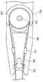
本発明を適用した超音波プローブの一実施形態について図を参照して説明する。図1は、本発明を適用した超音波プローブの構成図である。図1aは、超音波プローブの上面図、図1bは、超音波プローブを側面図、図1cは、超音波プローブの下面図である。なお、説明の便宜上、図1aの矢印Xの方向を左右方向、図1bの矢印Yの方向を上下方向と適宜称する。 An embodiment of an ultrasonic probe to which the present invention is applied will be described with reference to the drawings. FIG. 1 is a configuration diagram of an ultrasonic probe to which the present invention is applied. 1a is a top view of the ultrasonic probe, FIG. 1b is a side view of the ultrasonic probe, and FIG. 1c is a bottom view of the ultrasonic probe. For convenience of explanation, the direction of arrow X in FIG. 1a is appropriately referred to as the left-right direction, and the direction of arrow Y in FIG.
図1に示すように、超音波プローブは、中空筒状の挿入部10と、挿入部10の一端に連接された中空の把持部12と、挿入部10の先端に可撓継手14を介して連結された湾曲部16と、湾曲部16の先端に取り付けられた探触子18を備えている。可撓継手14は、径方向に自由度を有する例えばユニバーサル継手や湾曲継手を用いることができる。また、探触子18として、被検体の撮像部位(例えば、臓器)との間で超音波を送受する振動子が複数配設され、超音波射出面が凸面に形成された例えばコンベックス型の探触子が用いられる。探触子18は、挿入部10および把持部12内を挿通する配線を介して、超音波撮像装置に接続されている。 As shown in FIG. 1, the ultrasonic probe includes a hollow
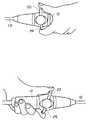
図2aは、超音波プローブの上方斜視図、図2bは、超音波プローブの下方斜視図である。図3は、超音波プローブの先端側(図1bの矢印A側)から見た平面図である。図1乃至図3に示すように、把持部12の外側に、第1の操作レバーとしての左右操作レバー20が支持部材21を介して設けられる。また、第2の操作レバーとしての上下操作レバー22も把持部12の外側に支持部材23を介して設けられている。左右操作レバー20と上下操作レバー22は、把持部12の周方向に隣り合わせて対称に配置され、かつ対称形に形成される。例えば、左右操作レバー20と上下操作レバー22は、左右方向に軸対称に並べて配列され、それぞれの上面が凹状に形成されている。これにより、操作者は、親指で左右操作レバー20と上下操作レバー22を操作し易くなる。 2a is an upper perspective view of the ultrasonic probe, and FIG. 2b is a lower perspective view of the ultrasonic probe. FIG. 3 is a plan view seen from the distal end side (arrow A side in FIG. 1B) of the ultrasonic probe. As shown in FIGS. 1 to 3, a left and right operation lever 20 as a first operation lever is provided outside the
また、図1乃至図3に示すように、把持部12の外側に、第1のブレーキレバーとしての左右ブレーキレバー24が支持部材25を介して設けられている。また、第2のブレーキレバーとしての上下ブレーキレバー26も支持部材27を介して把持部12の外側に設けられている。左右ブレーキレバー24と上下ブレーキレバー26は、左右操作レバー20と上下操作レバー22の操作レバーの反対側の周方向に隣り合わせて対称に配置され、かつ対称に形成される。例えば、図1bに示すように、左右ブレーキレバー24は、左右操作レバー20に対し上下方向に軸対称になるように起立し、その起立部の中央が縮径して形成されている。上下ブレーキレバー26についても、上下操作レバー22に対し上下方向に軸対称に設けられている。なお、左右操作レバー20と上下操作レバー22の位置や、左右ブレーキレバー24と上下ブレーキレバー26の位置を適宜入れ替えてもよいが、使い勝手の観点から、左右操作レバー20に対応させて左右ブレーキレバー24を位置させると共に、上下操作レバー22に対応させて上下ブレーキレバー26を位置させるのが好ましい。 Further, as shown in FIGS. 1 to 3, left and right brake levers 24 as first brake levers are provided on the outside of the
図4は、図1bのA−A断面図である。図5は、図1aのB−B断面図である。図4及び図5を参照して、湾曲部16を屈曲させる機構および湾曲部16を所望の位置及び角度で固定する機構を説明する。 FIG. 4 is a cross-sectional view taken along line AA in FIG. 1b. FIG. 5 is a cross-sectional view taken along the line BB in FIG. 1a. A mechanism for bending the bending
図4及び図5に示すように、把持部12の内部に挿入部10の軸に直交させて設けられたシャフト40と、シャフト40にそれぞれ回転自由に設けられた第1の回転部材としての巻取車42と第2の回転部材としての巻取車44と、巻取車42と巻取車44の挿入部10の軸を挟んだ二箇所にそれぞれ接続されると共に湾曲部16の内面の周方向に間隔をあけて固定された2組のワイヤ46、48が備えられている。 As shown in FIGS. 4 and 5, a
シャフト40は、把持部12の内部を軸方向に仕切る板状のフレーム50に、軸受け52を介して回転自在に挿入されている。シャフト40の一端に巻取車42、他端に巻取車44がそれぞれ同軸に回転可能に支持されている。巻取車42は、シャフト40に同軸に支持される大径部43、大径部43と同軸に連設される小径部45、小径部45に同軸に連設される支承部材58、支承部材58に同軸に連設されて把持部12の外側に位置し、支承部材58よりも径が大きい回転板60を有し形成されている。また、支承部材58と小径部45の連設部の外周を包囲すると共に回転板60に固定される回転部材59が配設されている。回転部材59は、支承部材58と小径部45と回転板60の回転に随伴して回転する。そして、図1及び図3に示すように、回転板60の周縁に、左右操作レバー20が支持部材21を介して例えばネジで取り付けられている。 The
なお、大径部43を包囲して巻取車42がシャフト40から脱落するのを阻止するカバー54が、例えばネジでフレーム50に固定されている。また、巻取車44は巻取車42と同様に構成されており、巻取車42と巻取車44はフレーム50に対し対称に配設されている。また、シャフト40とフレーム50の接触部分や、シャフト40と巻取車42および巻取車44の接触部分、あるいは、巻取車42および巻取車44とフレーム50の接触部分に、オイルなどの潤滑油が塗布されている。 A
また、図5に示すように、ワイヤ46は、一対の線材を有し、それぞれの線材の一端が巻取車42の大径部43の周縁に例えばロウ付けで固定され、他端がコネクタ47を介して湾曲部16内面に固定される。なお、線材は、例えばステンレス鋼線などを編んで形成された剛性の高く、柔軟性を有するものを用いればよい。また、ワイヤ48も、同様に、一対の線材を有し、それぞれの線材の一端が巻取車44の大径部の周縁に固定され、他端が湾曲部16内面に固定される。ワイヤ46の湾曲部16側の2つの固定端は、湾曲部16の内面の周方向に例えば180度ずれて固定されている。ワイヤ48の湾曲部16側の固定端は、ワイヤ46の固定端に対し周方向に例えば90度ずれて固定されている。この形態に限らず、要は、湾曲部16を所望方向に屈曲させるために、ワイヤ46、48を湾曲部16の内面の周方向に間隔をあけて固定すればよい。 As shown in FIG. 5, the
このような超音波プローブでは、左右操作レバー20を超音波プローブの長手方向に進退させると、回転板60と支承部材21を介して巻取車42が回転する。巻取車42の回転により、ワイヤ46の一方の線材が牽引され、他方の線材が撓む。これによって、湾曲部16が左右方向に屈曲する。同様に、上下操作レバー22を超音波プローブの長手方向に進退させると、湾曲部16が上下方向に屈曲する。 In such an ultrasonic probe, when the left and
次に、湾曲部16を所定位置に固定する機構について説明する。図4に示すように、巻取車42に接離可能に設けられる第1のブレーキ部材としてのブレーキリング70と、回転部材59に同軸に設けられ、ブレーキリング70を回転部材59に接離させる方向に駆動する力変換機構とを有する回転部材72が配設されている。回転部材72は、回転部材59の端面との間にギャップ(隙間)を形成し、回転部材72の外周に回転部材59に対し相対的に回転可能に配設されている。形成されたギャップにブレーキリング70が設けられている。ブレーキリング70は、樹脂系の材料(例えばポリアセタール)から形成されている。 Next, a mechanism for fixing the bending
回転部材72の外表面に雄ねじが刻設されている。回転部材72の外周に螺合する固定リング74が把持部12に固定されている。固定リング74の内周面に雌ねじが刻設されており、その雌ねじが回転部材72の雄ねじにねじ結合する。また、回転部材72の外側に位置する周縁につば状のフランジ76が形成されている。フランジ76に支持部材25を介して左右ブレーキレバー24が取り付けられている。 A male screw is engraved on the outer surface of the rotating
左右ブレーキレバー24を超音波プローブの長手方向に回転させると、その回転力により回転部材72が外側(図4の矢印S側)に移動する。回転部材72の移動により、回転部材72と回転部材59のネジ結合が締まると共に、回転部材72と回転部材59との間のギャップが減少してブレーキリング70が回転部材59に接触する。これによって、ブレーキリング70と回転部材59の接触部分に摩擦力が生じ、生じた摩擦力により巻取車42の回転が抑止されるため、湾曲部16が左右方向における所望の位置および角度で固定される。なお、左右ブレーキレバー24を逆方向に回転させると、その回転力により回転部材72が内側に移動してネジ結合が緩むと共にギャップが増大する。したがって、ブレーキリング70が回転部材59から離れることから、巻取車42は回転可能になる。左右ブレーキレバー24を中心に説明したが、上下ブレーキレバー26についても同様な機構で湾曲部16を上下方向における所望の位置および角度で固定できる。 When the left and
図6は、超音波プローブを片手で把持したときの例を示す図である。図6に示すように、操作者が手のひらで把持部12を把持したとき、把持した手の親指で左右操作レバー20又は上下操作レバー22を操作する。これによって、湾曲部16を左右方向又は上下方向に屈曲させて探触子18の超音波射出面を所定方向に臨ませる。また、左右操作レバー20又は上下操作レバー22を操作しつつ、同じ手の人差し指で左右ブレーキレバー24又は上下ブレーキレバー26を操作する。これによって、湾曲部16を所望の位置および角度で固定させる。 FIG. 6 is a diagram illustrating an example when the ultrasonic probe is held with one hand. As shown in FIG. 6, when the operator grips the
このような超音波プローブを例えばトラカールを介して被検体に挿入し、挿入した超音波プローブの湾曲部16を直交2方向(例えば、左右方向および上下方向)に屈曲させることにより、探触子の超音波射出面を撮像部位(例えば、臓器)の表面に接触または近接させる。次いで、探触子18に送信部から駆動信号を供給することによって、探触子18から超音波が撮像部位に対し送波される。撮像部位から発生した超音波は反射エコー信号として探触子18により受波される。探触子18から出力される反射エコー信号は、受信部により増幅や整相加算などの処理が施される。受信部から出力された反射エコー信号に基づき、超音波像(例えば、断層像や血流像)が画像処理部により再構成される。再構成された超音波像は、表示部に表示される。表示された超音波像を参照しながら、他方の手で保持した例えば生検針を体腔内に刺入して撮像部位の組織が採取される。 Such an ultrasonic probe is inserted into a subject via a trocar, for example, and the bending
本実施形態の超音波プローブによれば、左右操作レバー20と上下操作レバー22が把持部12の周方向に隣り合わせて対称に配置されることから、超音波プローブを片手で把持したとき、左右操作レバー20と上下操作レバー22の位置の特定が容易になり、超音波プローブの片手での使い勝手が向上する。しかも、左右操作レバー20と上下操作レバー22が対称形に形成されることから、操作者が左右のどちらの手で超音波プローブを把持するときでも、左右操作レバー20と上下操作レバー22の位置や形状が変わらないため、操作者の利き手にかかわらず、超音波プローブの使い勝手を向上させることができる。 According to the ultrasonic probe of the present embodiment, the left /
また、左右ブレーキレバー24と上下ブレーキレバー26が、左右操作レバー20と上下操作レバー22の反対側の周方向に隣り合わせて対称に配置され、かつ対称形に形成されることから、湾曲部16を所望の位置で固定する操作も、片手で簡単に行うことができる。また、左右ブレーキレバー24と上下ブレーキレバー26のそれぞれは、起立部の中央が縮径して形成されていることから、人差し指の外側で押し易く、使い勝手が向上する。 Further, since the left and right brake levers 24 and the upper and lower brake levers 26 are symmetrically disposed adjacent to each other in the circumferential direction on the opposite side of the left and right operation levers 20 and the upper and lower operation levers 22 and are formed symmetrically, the bending
また、ブレーキリング70や回転部材72を回転部材59に対し同軸に設けるようにしたことから、湾曲部を固定する機構の部品点数を減らすことができ、また容易に組立てることができる。 Further, since the
また、探触子18としてコンベックス型のものを用いたが、リニア型あるいはラジアル型の探触子を用いることもできる。このとき、コンベックス型やリニア型を用いると、超音波像として表示される撮像部位と実際の撮像部位との位置の対応関係を把握し易いため、例えば生検針の刺入が容易になる。 Further, although the convex type is used as the
なお、本発明を適用した超音波プローブを説明したが、腹腔用のものに限らず様々なものに適用することができる。要するに、先端部を湾曲させるものであれば、いずれの形態にも本発明を適用することができる。また、体内に挿入する内視鏡などにも適用することができる。 In addition, although the ultrasonic probe to which the present invention is applied has been described, the present invention can be applied not only to the abdominal cavity but also to various types. In short, the present invention can be applied to any form as long as the tip is curved. It can also be applied to an endoscope inserted into the body.
10 挿入部
12 把持部
14 可撓継手
16 湾曲部
18 探触子
20 左右操作レバー
22 上下操作レバー
24 左右ブレーキレバー
26 上下ブレーキレバー
40 シャフト
42、44 巻取車
46、48 ワイヤ
59 回転部材
70 ブレーキリング
72 回転部材DESCRIPTION OF
Claims (3)
Translated fromJapaneseA transmission / reception unit comprising the ultrasonic probe according to claim 1, supplying a drive signal to the probe of the ultrasonic probe and receiving a reflected echo signal output from the probe, and the transmission / reception An ultrasonic imaging apparatus comprising: an image processing unit that reconstructs an ultrasonic image based on a reflected echo signal output from the unit; and a display unit that displays the reconstructed ultrasonic image.
Priority Applications (1)
| Application Number | Priority Date | Filing Date | Title |
|---|---|---|---|
| JP2004177092AJP2006000201A (en) | 2004-06-15 | 2004-06-15 | Ultrasonic probe and ultrasonic imaging device |
Applications Claiming Priority (1)
| Application Number | Priority Date | Filing Date | Title |
|---|---|---|---|
| JP2004177092AJP2006000201A (en) | 2004-06-15 | 2004-06-15 | Ultrasonic probe and ultrasonic imaging device |
Publications (1)
| Publication Number | Publication Date |
|---|---|
| JP2006000201Atrue JP2006000201A (en) | 2006-01-05 |
Family
ID=35769110
Family Applications (1)
| Application Number | Title | Priority Date | Filing Date |
|---|---|---|---|
| JP2004177092APendingJP2006000201A (en) | 2004-06-15 | 2004-06-15 | Ultrasonic probe and ultrasonic imaging device |
Country Status (1)
| Country | Link |
|---|---|
| JP (1) | JP2006000201A (en) |
Cited By (2)
| Publication number | Priority date | Publication date | Assignee | Title |
|---|---|---|---|---|
| JP2009213640A (en)* | 2008-03-10 | 2009-09-24 | Toshiba Corp | Ultrasonic probe |
| CN112426634A (en)* | 2019-08-26 | 2021-03-02 | 重庆海扶医疗科技股份有限公司 | Ultrasonic probe motion mechanism and ultrasonic probe assembly |
- 2004
- 2004-06-15JPJP2004177092Apatent/JP2006000201A/enactivePending
Cited By (2)
| Publication number | Priority date | Publication date | Assignee | Title |
|---|---|---|---|---|
| JP2009213640A (en)* | 2008-03-10 | 2009-09-24 | Toshiba Corp | Ultrasonic probe |
| CN112426634A (en)* | 2019-08-26 | 2021-03-02 | 重庆海扶医疗科技股份有限公司 | Ultrasonic probe motion mechanism and ultrasonic probe assembly |
Similar Documents
| Publication | Publication Date | Title |
|---|---|---|
| US8083681B2 (en) | Ultrasonic probe | |
| JP2006167465A (en) | Array rotation for ultrasonic catheter | |
| JP2010000210A (en) | Probe | |
| JP6203132B2 (en) | Guide device and surgical system | |
| EP3020320A1 (en) | Introduction device | |
| JP4402222B2 (en) | Body cavity ultrasound probe system | |
| JPS6357060B2 (en) | ||
| JP6653668B2 (en) | Ultrasound endoscope | |
| JP2006000201A (en) | Ultrasonic probe and ultrasonic imaging device | |
| JP5985130B1 (en) | Insertion device | |
| JP2953305B2 (en) | Ultrasound endoscope device | |
| JP3367339B2 (en) | Medical probe guidance device | |
| JP3852183B2 (en) | Ultrasonic probe | |
| JP2005211683A (en) | Treatment tool | |
| JP2010012007A (en) | Ultrasonic examination apparatus | |
| JP3149643B2 (en) | Ultrasonic inspection equipment | |
| JP2003310620A (en) | Ultrasonic endoscope | |
| JPH0730010Y2 (en) | Ultrasonic probe | |
| JP2682244B2 (en) | Radial scanning ultrasonic inspection system | |
| JPH07222749A (en) | Ultrasonic diagnostic device | |
| JPH0744930B2 (en) | Ultrasonic inspection device | |
| JPH0130164Y2 (en) | ||
| JPH10192279A (en) | Ultrasonic probe in body cavity | |
| JPH0856946A (en) | Coil shaft | |
| JPH07289551A (en) | Ultrasonic diagnostic equipment |