JP2005537102A - Fixation system consisting of nails and screws to improve the fixation of proximal fractures of the humerus - Google Patents
Fixation system consisting of nails and screws to improve the fixation of proximal fractures of the humerusDownload PDFInfo
- Publication number
- JP2005537102A JP2005537102AJP2004533434AJP2004533434AJP2005537102AJP 2005537102 AJP2005537102 AJP 2005537102AJP 2004533434 AJP2004533434 AJP 2004533434AJP 2004533434 AJP2004533434 AJP 2004533434AJP 2005537102 AJP2005537102 AJP 2005537102A
- Authority
- JP
- Japan
- Prior art keywords
- screw
- nail
- intermediate plate
- hole
- head
- Prior art date
- Legal status (The legal status is an assumption and is not a legal conclusion. Google has not performed a legal analysis and makes no representation as to the accuracy of the status listed.)
- Granted
Links
- 210000002758humerusAnatomy0.000titleclaimsabstractdescription13
- 238000003780insertionMethods0.000claimsabstractdescription6
- 230000037431insertionEffects0.000claimsabstractdescription6
- 210000000988bone and boneAnatomy0.000claimsdescription29
- 239000012634fragmentSubstances0.000claimsdescription29
- 230000001154acute effectEffects0.000claimsdescription2
- 230000003014reinforcing effectEffects0.000claimsdescription2
- 206010017076FractureDiseases0.000description14
- 208000010392Bone FracturesDiseases0.000description12
- 210000004095humeral headAnatomy0.000description9
- 230000001009osteoporotic effectEffects0.000description6
- 238000006073displacement reactionMethods0.000description5
- 208000007981Humeral FracturesDiseases0.000description4
- 206010020462Humerus fractureDiseases0.000description4
- 210000000852deltoid muscleAnatomy0.000description4
- 208000001132OsteoporosisDiseases0.000description3
- 208000002103Shoulder FracturesDiseases0.000description3
- 230000009471actionEffects0.000description3
- 239000000463materialSubstances0.000description3
- 238000001356surgical procedureMethods0.000description3
- 210000001185bone marrowAnatomy0.000description2
- 239000000835fiberSubstances0.000description2
- 230000035876healingEffects0.000description2
- 230000004048modificationEffects0.000description2
- 238000012986modificationMethods0.000description2
- 210000003205muscleAnatomy0.000description2
- 230000000399orthopedic effectEffects0.000description2
- 238000007711solidificationMethods0.000description2
- 230000008023solidificationEffects0.000description2
- 229910000811surgical stainless steelInorganic materials0.000description2
- 229910001069Ti alloyInorganic materials0.000description1
- RTAQQCXQSZGOHL-UHFFFAOYSA-NTitaniumChemical compound[Ti]RTAQQCXQSZGOHL-UHFFFAOYSA-N0.000description1
- 230000008859changeEffects0.000description1
- 238000005553drillingMethods0.000description1
- 230000009977dual effectEffects0.000description1
- 230000000694effectsEffects0.000description1
- 210000002310elbow jointAnatomy0.000description1
- 210000003041ligamentAnatomy0.000description1
- 238000007712rapid solidificationMethods0.000description1
- 230000009467reductionEffects0.000description1
- 230000008439repair processEffects0.000description1
- 210000000323shoulder jointAnatomy0.000description1
- 210000001519tissueAnatomy0.000description1
- 229910052719titaniumInorganic materials0.000description1
- 239000010936titaniumSubstances0.000description1
Images


Classifications
- A—HUMAN NECESSITIES
- A61—MEDICAL OR VETERINARY SCIENCE; HYGIENE
- A61B—DIAGNOSIS; SURGERY; IDENTIFICATION
- A61B17/00—Surgical instruments, devices or methods
- A61B17/56—Surgical instruments or methods for treatment of bones or joints; Devices specially adapted therefor
- A61B17/58—Surgical instruments or methods for treatment of bones or joints; Devices specially adapted therefor for osteosynthesis, e.g. bone plates, screws or setting implements
- A61B17/68—Internal fixation devices, including fasteners and spinal fixators, even if a part thereof projects from the skin
- A61B17/72—Intramedullary devices, e.g. pins or nails
- A61B17/7233—Intramedullary devices, e.g. pins or nails with special means of locking the nail to the bone
- A—HUMAN NECESSITIES
- A61—MEDICAL OR VETERINARY SCIENCE; HYGIENE
- A61B—DIAGNOSIS; SURGERY; IDENTIFICATION
- A61B17/00—Surgical instruments, devices or methods
- A61B17/56—Surgical instruments or methods for treatment of bones or joints; Devices specially adapted therefor
- A61B17/58—Surgical instruments or methods for treatment of bones or joints; Devices specially adapted therefor for osteosynthesis, e.g. bone plates, screws or setting implements
- A61B17/68—Internal fixation devices, including fasteners and spinal fixators, even if a part thereof projects from the skin
- A61B17/72—Intramedullary devices, e.g. pins or nails
- A61B17/7283—Intramedullary devices, e.g. pins or nails with special cross-section of the nail
- A—HUMAN NECESSITIES
- A61—MEDICAL OR VETERINARY SCIENCE; HYGIENE
- A61B—DIAGNOSIS; SURGERY; IDENTIFICATION
- A61B17/00—Surgical instruments, devices or methods
- A61B17/56—Surgical instruments or methods for treatment of bones or joints; Devices specially adapted therefor
- A61B17/58—Surgical instruments or methods for treatment of bones or joints; Devices specially adapted therefor for osteosynthesis, e.g. bone plates, screws or setting implements
- A61B17/68—Internal fixation devices, including fasteners and spinal fixators, even if a part thereof projects from the skin
- A61B17/80—Cortical plates, i.e. bone plates; Instruments for holding or positioning cortical plates, or for compressing bones attached to cortical plates
- A—HUMAN NECESSITIES
- A61—MEDICAL OR VETERINARY SCIENCE; HYGIENE
- A61B—DIAGNOSIS; SURGERY; IDENTIFICATION
- A61B17/00—Surgical instruments, devices or methods
- A61B17/56—Surgical instruments or methods for treatment of bones or joints; Devices specially adapted therefor
- A61B17/58—Surgical instruments or methods for treatment of bones or joints; Devices specially adapted therefor for osteosynthesis, e.g. bone plates, screws or setting implements
- A61B17/68—Internal fixation devices, including fasteners and spinal fixators, even if a part thereof projects from the skin
- A61B17/84—Fasteners therefor or fasteners being internal fixation devices
- A61B17/86—Pins or screws or threaded wires; nuts therefor
Landscapes
- Health & Medical Sciences (AREA)
- Orthopedic Medicine & Surgery (AREA)
- Surgery (AREA)
- Life Sciences & Earth Sciences (AREA)
- Heart & Thoracic Surgery (AREA)
- Nuclear Medicine, Radiotherapy & Molecular Imaging (AREA)
- Engineering & Computer Science (AREA)
- Biomedical Technology (AREA)
- Neurology (AREA)
- Medical Informatics (AREA)
- Molecular Biology (AREA)
- Animal Behavior & Ethology (AREA)
- General Health & Medical Sciences (AREA)
- Public Health (AREA)
- Veterinary Medicine (AREA)
- Surgical Instruments (AREA)
Abstract
Translated fromJapaneseDescription
Translated fromJapanese本発明は、骨折部を治療するための釘に関し、より詳細には、上腕骨の体幹近接骨折部の固定を改善するための釘に関する。 The present invention relates to a nail for treating a fracture, and more particularly to a nail for improving fixation of a proximal humeral fracture.
また本発明は、上腕骨幹に挿入するための少なくとも1つの上腕骨用釘を備え、前記釘は、対応するロックネジを通過させるための、少なくとも1つの体幹近接横孔を備え、かつ前記ネジは、ヘッドとネジ軸とを有するシステムに関する。 The invention also comprises at least one humeral nail for insertion into the humeral shaft, the nail comprising at least one trunk proximate lateral hole for passing a corresponding locking screw, and the screw And a system having a head and a screw shaft.
このような特殊な整形外科分野で周知のように、上腕骨では、体幹近接部での骨折が最も多い。 As is well known in the special orthopedic field, the humerus has the highest number of fractures in the vicinity of the trunk.
上腕骨は上方部分を有し、この上方部分は、肩にあるボールとソケットの関節と見なすことができる。上腕骨の体幹近接端部は、ボール部分を含む拡大された頭部を有する。上腕骨幹は、体幹近接端部から肘関節に向かって延びている。 The humerus has an upper portion, which can be considered as a ball and socket joint on the shoulder. The proximal end of the humerus has an enlarged head that includes a ball portion. The humeral shaft extends from the proximal end of the trunk toward the elbow joint.
単純な上腕骨の体幹近接部の骨折は、上腕頭、すなわち、頭の一部が上腕骨幹から折れた状態となり、この骨折に伴う変位は小さい。 A simple fracture of the proximal portion of the trunk of the humerus results in a state where the humeral head, that is, a part of the head is broken from the humeral shaft, and the displacement accompanying the fracture is small.
上腕骨の複雑な骨折は、大きな変位をもたらし、かつ上腕頭部分が、2つ、3つまたは4つの部分に破壊される。 A complex fracture of the humerus results in a large displacement and the humeral head part is broken into two, three or four parts.
上腕頭のこれら変位した部分は、フラグメント(骨折片)と呼ばれている。 These displaced parts of the humeral head are called fragments (fracture pieces).
上腕頭は、ボール部分と靭帯が接続しているの上腕頭の1つまたは双方の小隆起との間で、骨折する傾向があるので、上腕骨の骨折の性質は、通常予測することができる。しかし、上腕骨の骨折を整復することは、整形外科手術における最も複雑な手術の1つである。 Because the humeral head tends to fracture between the ball portion and one or both small ridges of the humeral head to which the ligament is connected, the nature of the humeral fracture can usually be predicted. . However, reducing humeral fractures is one of the most complex operations in orthopedic surgery.
従来技術によれば、肩関節を、手術によってプロテーゼに置換することができる。しかし、この解決方法は、多くの見地から、患者にとって満足のし難いものである。 According to the prior art, the shoulder joint can be replaced with a prosthesis by surgery. However, this solution is unsatisfactory for the patient from many perspectives.
最近、新しい温存外科技術ロックネジと共に、上腕骨用釘を使用することが、次第に受け入れられつつある。 Recently, the use of humeral nails with new conservative surgical lock screws is becoming increasingly accepted.
釘内の近接する孔へ挿入したネジを使って、フラグメントの整復が行われ、釘は、固化が生じる間、上腕骨の近接端部に挿入される。 Fragment reduction is performed using screws inserted into adjacent holes in the nail and the nail is inserted into the proximal end of the humerus while solidification occurs.
この種の釘は、例えば固定ネジを保持するための横孔を備えるシャフトを有する上腕骨用釘を開示するドイツ国特許願第199 45 611号により公知である。シャフトの体幹近接部内のいくつかの孔は、ネジをフラグメントを異なる方向に保持できるように、高さおよび角度が異なっている。 This type of nail is known, for example, from German Patent Application No. 199 45 611 which discloses a humeral nail having a shaft with a transverse hole for holding a fixing screw. Some holes in the proximate torso of the shaft are different in height and angle so that the screw can hold the fragment in different directions.
米国特許第5,472,444号にも、同様の解決案が開示されている。この米国特許は、フラグメントに取り付けられたネジを嵌合しうるように、選択された角度を向いている横孔を有する上腕骨用釘を開示している。 US Pat. No. 5,472,444 also discloses a similar solution. This US patent discloses a humeral nail having a transverse hole oriented at a selected angle so that a screw attached to the fragment can be fitted.
この種の上腕骨用釘およびロックネジを使用する際、ネジのネジ山部分は、時間が経つにつれ、安定性および固化特性を失う傾向があることが判っている。換言すれば、対応するフラグメント内に埋め込まれたネジのネジ切りされた部分は、締結効果を失う。その理由は、多孔質の骨では、ネジが横孔内で自由に移動したり、回転できる状態のままになるからである。 When using this type of humeral nail and lock screw, it has been found that the thread portion of the screw tends to lose stability and solidification characteristics over time. In other words, the threaded portion of the screw embedded in the corresponding fragment loses the fastening effect. The reason is that in porous bone, the screw remains free to move or rotate within the side hole.
この問題は、高齢者の骨粗鬆症患者、または骨折領域にガン性組織を有する患者で特に問題となる体幹近接部の上腕骨骨折部で、より顕著である。 This problem is more pronounced in humeral fractures near the trunk, which are particularly problematic in elderly osteoporosis patients or patients with cancerous tissue in the fracture area.
このような更なる問題を解決するために、小さい骨フラグメントを、格子構造によって固定するようになっている、少なくとも3つの体幹近接ネジ孔、および完全にネジ切りされたネジを含む上腕骨用釘を使用することによる解決策が、最近提案されている。 To solve such further problems, for humeral bones comprising at least three core proximate screw holes and fully threaded screws adapted to fix small bone fragments by a lattice structure A solution using nails has recently been proposed.
骨フラグメントは、ネジ孔にネジを簡単にロックすることにより、骨のフラグメントを釘に対して固定し、所定位置に保持される。こうしてネジは、釘内で安定する。 The bone fragment is held in place by securing the bone fragment to the nail by simply locking the screw in the screw hole. The screw is thus stabilized in the nail.
上述した解決策により、上腕骨の体幹近接骨折部を短時間で再構成することが可能であるが、このような最近の解決案では、骨折部が解剖学的に整復された後に、ネジのヘッドの少なくとも1つが、骨フラグメント、特に小さい隆起部によって隠されたままとなり、深刻な問題を引き起こしている。従って、固化した後に、釘からこのネジを短時間で除くことは不可能であり、そのため、ネジを短時間で除去する上で問題がある。 Although the above-mentioned solution enables the reconstruction of the proximal humeral fracture of the humerus in a short time, in such a recent solution, after the fracture is anatomically reduced, the screw At least one of the heads remains hidden by bone fragments, especially small ridges, causing serious problems. Therefore, it is impossible to remove the screw from the nail in a short time after solidifying, and there is a problem in removing the screw in a short time.
更に、完全にネジ切りされたネジを使った場合でも、骨粗鬆症患者に生じる問題は、完全には解決されない。その理由は、フラグメントは、釘に向かって引っ張られるが、骨粗鬆症の骨内では、ネジのネジ山部分は、ネジの回転、および対応するネジ孔からの外れを防止するのに必要な安定性が得られないからである。 Furthermore, even with the use of fully threaded screws, the problems that occur in osteoporotic patients are not completely solved. The reason is that the fragment is pulled towards the nail, but within the osteoporotic bone, the thread portion of the screw has the necessary stability to prevent screw rotation and disengagement from the corresponding screw hole. It is because it cannot be obtained.
別の欠点は、ネジを任意の方法に挿入することはできず、釘に対して横方向を向いたままにしなければならず、すべてのフラグメントを締結するのに最適な方向に向けることはできないということである。 Another drawback is that the screw cannot be inserted in any way, it must remain sideways with respect to the nail and cannot be oriented in the optimum direction for fastening all the fragments That's what it means.
フランス国特許公開第2784283号には、従来技術の解決案が開示されている。このフランス国特許出願では、ネジを骨から解放したときに、ネジ3を係合するための釘の孔に対して、横方向を向く特殊なピン10が設けられている。 French Patent Publication No. 2784283 discloses a prior art solution. In this French patent application, a
しかし、この解決案は、カニューレとなっている上腕骨骨折部のための釘に関するものではなく、このような釘には適用できない。 However, this solution does not relate to a nail for a humeral fracture that is a cannula and is not applicable to such a nail.
本発明の目的は、従来技術による解決案に伴う欠点を有せず、特に異なる方向に沿って、対応する釘孔にネジを容易に挿入できるようにし、骨粗鬆症の骨においてさえも、上腕骨の体幹近接骨折部の固定を改善するようにした、新しい固定システムを提供することにある。 The object of the present invention does not have the disadvantages associated with prior art solutions, and allows for easy screw insertion into the corresponding nail holes, especially along different directions, even in osteoporotic bones. It is an object of the present invention to provide a new fixation system that improves the fixation of a fracture near the trunk.
本発明の別の目的は、手術中に使用が容易な締結手段により、上腕骨の体幹近接骨折部の固定および硬化を行わせるようにすることにある。 Another object of the present invention is to fix and harden the proximal fracture of the humerus with a fastening means that is easy to use during surgery.
本発明の別の目的は、かかるフラグメントの締結作用をより強くし、しかも、骨粗鬆症の骨フラグメントにかかる応力を低減させるようにすることにある。 Another object of the present invention is to make the fastening action of such fragments stronger and to reduce the stress on osteoporotic bone fragments.
本発明の別の目的は、外科医が骨を囲む筋肉の切開を小さくして、多数のフラグメントを一体に固定できるようにすることにある。 Another object of the present invention is to allow the surgeon to reduce the muscle incision surrounding the bone so that multiple fragments can be secured together.
本発明の一実施例によれば、上腕骨幹に挿入しうる少なくとも1つの上腕骨用釘を備え、かつ前記釘が対応するロックネジを通過させるための、少なくとも1つの体幹近接横孔を備え、前記ネジは、ネジヘッドとネジ本体とを有する新規な釘とネジの固定システムが提供される。 According to one embodiment of the present invention, at least one humeral nail that can be inserted into the humeral shaft, and at least one trunk proximate lateral hole through which the nail passes a corresponding locking screw; The screw is provided with a novel nail and screw fixing system having a screw head and a screw body.
前記横孔は、内側の一部にネジ切りされた部分を有し、前記ネジは、このネジが嵌合される少なくとも1つの前記横孔の直径よりも小さいネジの外径を有する。 The lateral hole has a portion threaded on a part of the inner side, and the screw has an outer diameter of a screw smaller than a diameter of at least one of the lateral holes into which the screw is fitted.
一部にネジ切りされた部分は、ナットネジの一部として機能するが、正常に挿入される間は、ネジとは干渉しない。最終締結後、または使用中に、ネジが望ましくない移動または変位をする場合、雌ネジ部分は、少なくともネジ山の頂点と頂点とが係合するという問題を解決する。 The part that is threaded functions as part of the nut screw, but does not interfere with the screw during normal insertion. If the screw undergoes undesired movement or displacement after final fastening or during use, the female thread portion solves the problem that at least the apex of the thread engages.
この解決策により、骨粗鬆症の骨内で、ネジが移動したり、外れたりした場合でも、対応する孔内で、釘内のネジを所定位置に保持するとともに、安定に保持できる。 With this solution, even if the screw moves or comes off in the osteoporotic bone, the screw in the nail can be held in a predetermined position and stably held in the corresponding hole.
添付した図面に示す本発明を限定しない好ましい実施例の次の説明から、本発明にかかわる釘およびネジシステムの上記以外の利点および特徴が明らかとなると思う。 Additional advantages and features of the nail and screw system according to the present invention will become apparent from the following description of the preferred embodiment, not limiting of the present invention, shown in the accompanying drawings.
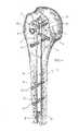
図において、上腕骨の体幹近接骨折部の固定を改善するための釘およびネジシステム全体が1で示されている。 In the figure, the entire nail and screw system for improving the fixation of the proximal humeral fracture is shown at 1.
本発明にかかわる固定システム1は、上腕骨幹9に直接挿入される上腕骨用釘10を備えている。この釘10は、カニューレとなっており、骨髄腔8に挿入しうる。 The fixation system 1 according to the present invention includes a
釘10は、その全長にわたって円杆状でもよいし、または先端部に、円錐形のテーパがついていてもよい。すなわち、釘10は、その長手方向にわたって、一定の円形断面でもよいし、変化していてもよく、またカーブした部分を有していてもよい。釘の形状および長さは、本発明のシステムの限定的特徴ではない。 The
釘10の先端は、半球状の閉鎖端部11となっており、ノーズを形成している。 The tip of the
釘10の先端部には、ロックネジを嵌合しうる先端横孔12,13が設けられている。例えば図6に示すように、各横孔12、13には、ロックネジ32、33が嵌合され、これらのネジは、釘を一旦上腕骨幹9に挿入すると、釘10を固定するようになっている。 At the tip of the
本発明の第1実施例によれば、固定システム1は、上腕骨釘10と少なくとも1つの体幹近接ロックネジ3とを備えている。 According to a first embodiment of the invention, the fixation system 1 comprises a
上腕骨用釘10の基端部には、対応するロックネジ3のための基端横孔が設けられている。例えばこの実施例では、図7に示すように、上腕骨用釘10の基端部には、少なくとも3つの基端横孔5、6、7が設けらている。 The proximal end of the
より詳細には、上腕骨用釘10は、カニューレとなっており、各横孔5、6、7は、対向する壁を貫通し、軸線方向に整合している。説明上、各壁を貫通して対向している孔を、1つの横孔と見なすことにする。 More specifically, the
各横孔は、釘の長手方向の軸線に対して、選択された角度に向けられている。しかし、近接孔の前記グループのうちの少なくとも2つの横孔5、6は、同一平面にあるが、第3の横孔7は直交している。 Each transverse hole is oriented at a selected angle with respect to the longitudinal axis of the nail. However, at least two
ロックネジ3は、全体にネジ切りされていることが好ましく、ヘッド4と、ネジ軸31と、ヘッドと反対側の丸い先端部34とを備えている。ヘッド4には、外科医が使用する図示されていない作動キーを嵌合しうる凹入孔29が設けられている。 The
ネジ山の形状については、後で詳細に説明する。しかし、本発明に係わる固定システム1においては、ロックネジ3の形状やネジ山の形状については任意である。 The shape of the thread will be described in detail later. However, in the fixing system 1 according to the present invention, the shape of the
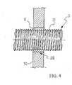
この特定の実施例では、上腕骨用釘10の少なくとも基端横孔6は、図4および図5に明瞭に示されるように、一部に雌ネジが切られたネジ部28を有する。このネジ部28は、ナットネジの一部と見なすことができるが、ルーレットが付けられた部分としても、本発明の目的を満たすことができる。 In this particular embodiment, at least the proximal
上記のように、上腕骨用釘はカニューレとなっているので、各横孔は、釘の対向する壁に設けられ、軸線方向に整合する1組の孔からなっている。 As described above, since the humeral nail is a cannula, each lateral hole is formed in a pair of holes provided in opposing walls of the nail and aligned in the axial direction.
この実施例では、横孔6を形成する2つの対向する整合孔6’、6”が設けられている。 In this embodiment, two opposing
各ロックネジ3は、ネジが嵌合される横孔6の直径よりも小さい径を有し、前記ネジ部28は、通常の挿入状態では、ロックネジ3と干渉しない。 Each
好ましい実施例では、ロックネジのヘッド4に近い方の整合孔6’内に、ネジ部28が設けられる。 In the preferred embodiment, a threaded
ロックネジ3は、整合孔6’、6”を通って所定位置に挿入することができ、固定するべき骨フラグメント内にねじ込まれる。 The locking
最終締結後、または使用中に、ロックネジ3が、望ましくない移動または変位をした場合には、ネジ部28は、図4に示されるように、少なくともネジ山の頂点と頂点とが係合するという問題を起こすことはない。 If the
前に述べたように、ロックネジ3は、特定の形状およびネジ切り部を有するものとすることができる。次に、好ましいネジの形態について述べる。 As described above, the
ロックネジ3は、完全にネジ切りされたネジ軸31を有する。 The
このネジ切りされたネジ軸31は、丸い先端部34で終端するまで、直径が一定のほぼ円筒状となっている。 The threaded
図6は、本発明におけるネジ切りされた部分の拡大図である。 FIG. 6 is an enlarged view of a threaded portion in the present invention.
ネジ切りされた部分は、一定ピッチp、好ましくは0.45mmピッチを有し、60度の尖頭または鋭角の頂角を有する断面が三角形のネジ山35を備えている(図2)。 The threaded portion has a constant pitch p, preferably 0.45 mm pitch, and includes a
2つの隣接するネジ山35の対向する側面は、60度の角度αをなしている。 The opposing sides of two
ネジ山35における隣接する側面間のネジ山の底部は、丸味のある凹状であり、材料の流れを容易にし、かつロックネジが進入する間、骨の応力を緩和するように作用する。 The bottom of the thread between adjacent sides of the
底部の丸味のある部分の半径は、0.5mmである。
ネジ山35の高さhは0.27mmであり、軸線に沿って一定である。
このネジ山のために、ロックネジの先端を円錐形プロフィルとすることも可能となっている。The radius of the rounded portion at the bottom is 0.5 mm.
The height h of the
Because of this thread, the tip of the lock screw can also have a conical profile.
本発明のロックネジ3は、従来のロックネジに比して、より良好に応力を分散する。また、本発明のロックネジ3は、干渉がない場合でも、すなわち、オーバーサイズの予めドリル加工された孔、または骨粗鬆症の状況でも、圧縮力を良好に分散させる。 The
図6〜図15には、本発明の別の実施例が示されている。 6 to 15 show another embodiment of the present invention.
この実施例では、固定システム1は、ロックネジ3を最終締結位置に固定するための締結装置2を備えている。 In this embodiment, the fixing system 1 includes a
既に述べたように、ロックネジ3は、対応するヘッド4を有し、このヘッド4は、従来技術に従い、常時、上腕骨用釘10または上腕骨の皮質に係合する。 As already mentioned, the locking
これに反し、本発明のシステムによれば、締結装置2は、ヘッド4と、骨の皮質14との間に挟持される。より詳細には、前記締結装置2は、少なくとも1つの中間のプレート15を備え、このプレート15は、前記ヘッド4と骨の皮質14との間に挿入される。 On the contrary, according to the system of the present invention, the
従って、ロックネジ3を完全に締結すると、ヘッド4は、骨の皮質14に当接する代わりに、中間プレート15に当接する。 Therefore, when the
そのため、ロックネジ3のヘッド4の当接面を、骨皮質14の面に対して拡大し、よって、より強力な締結作用を可能にし、かつロックネジ3が更に回転することが防止される。更に、この解決案によって、外科医がより小さい切断部を有する多数のフラグメントを一体に固定できるようになる。 Therefore, the contact surface of the
前記プレート15は、図5および図7に示されているように、骨の皮質14に完全に付着するべき若干湾曲した表面16を有することが好ましい。好ましい実施例では、プレート15は、主要軸方向の双方に若干曲がっているので、2つの対向し、かつ閉口な湾曲した表面16および17が提供されている。 The
次に、中間プレート15の形状および寸法に関して述べる。プレート15の全体を、直径が18mmの円の内部に嵌合することができ、プレートの厚さは約1mmである。 Next, the shape and dimensions of the
中間プレート15とロックネジ3とは、手術用スチールから製造されている。これらを、チタンまたはチタン合金で製造してもよい。 The
別の可能な手段として、中間プレート15を、プラスチック材料または生物学的に分解可能な材料によって製造してもよい。 As another possible means, the
更に中間プレート15は、ほぼ円形となっている。このプレートは、ネジのヘッド4に対する最終締結作用の前に、ネジ軸に挿入される1組の細長いアーム部18、19を備えている。 Furthermore, the
前記各アーム部分18、19は、丸い端部18a、19aを有する。 Each
前記中間プレート15は、図1および図2に示すように、骨内に挿入される少なくとも1つのフラグメントロックネジ32を補強するための、図10ほかに示された、少なくとも1つの拡大部21を備えている。 As shown in FIGS. 1 and 2, the
好ましい実施例では、前記シート22は、中間プレート15の前記拡大された部分21には孔24があけられている。この孔24は、例えば2.5mmの直径を有している。 In a preferred embodiment, the
好ましい実施例では、図10に示すように、対応する各アーム部18、19に整合するよう、前記拡大部21には、少なくとも2つの孔24が設けられている。 In the preferred embodiment, as shown in FIG. 10, the
図13に示すように、アーム部18または19の一方の先端部の近くに、1つの孔24を設けることもできる。 As shown in FIG. 13, one
これまでの説明によれば、中間プレート15は、拡大部21が一体的に形成されたオープンワッシャーと見なすことができる。 According to the description so far, the
フラグメント固定ピン23は、ネジ切り部25を有する手術用スチール製の細いロッド26である。このロッドは、3mmの直径を有し、かつそのネジ切り部分は、2.5mm未満の外径を有するものとすることができる。 The
図9に示す、本願出願人を名義人とするヨーロッパ特許第0642323号には、このフラグメント固定ピン23が示されている。 The
外科医が、骨折した骨端隗状部に到達するように、三角筋内に前方の開口部を設けた後、三角筋繊維と直線状に短い切開を行う。次に、三角筋繊維を分割し、骨折領域および対応するエマトーマにアクセスする。 The surgeon provides a front opening in the deltoid muscle so as to reach the fractured epiphyseal ridge, and then makes a short incision linearly with the deltoid muscle fiber. Next, the deltoid muscle fibers are split to access the fracture region and the corresponding emmatoma.
上腕骨幹9の軸内に釘10を挿入し、ロックネジ32、33により、所定位置に維持する。次に、フラグメントを上腕骨用釘10に固定することにより、上腕骨ヘッドの骨折を修復することができる。 The
ロックネジ3を受ける前に、一旦位置決めされた骨折部(より軽度の骨粗鬆症、より重度の骨粗鬆症に対しては上腕頭など)を、適当な工具を用いて切開ドリル処理する。 Prior to receiving the
ロックネジをロックし、ネジを最終締結する前に、ヘッド4と骨皮質14との間の中間プレート15を、ネジ軸にまたがった位置に位置決めする。中間プレート15を挿入するのに、例えば4cmの三角筋を、極めて小さく切開する必要がある。これにより、治癒を助けることができることを指摘しておく。 Before locking the locking screw and finally fastening the screw, the
中間プレート15を最終位置に位置決めし、ネジのヘッド4が中間プレート15に当接するように、ロックネジ3を締結すると、孔24を介して、骨内にフラグメント固定ピン23を挿入できる。 When the
ピンのネジ部を強固に係合するのに十分小さくて、骨を貫通する孔を、ドリル加工することにより、骨にフラグメント固定ピン23を挿入できる。 The
ネジ切り部分の直径は、孔24の直径よりもわずかに小さいので、上腕頭の他の可能なフラグメントを係合する必要性に従って、固定ピン23を配向することができる。 Since the diameter of the threaded portion is slightly smaller than the diameter of the
固定ピン23を設けたことにより、中間プレート15の変位または回転を防止すると共に、必要な場合に、上腕頭のフラグメントを固定できるという二重の機能が得られる。 Providing the fixing
本発明の好ましい実施例によれば、図6または図8の例に示されているような形状の中間プレート15の孔24を通して、骨に1組のフラグメント固定ピン23が挿入される。 According to a preferred embodiment of the present invention, a set of fragment fixation pins 23 are inserted into the bone through the
しかし、前に述べたように、中間プレート15の変位を防止するには、1つの固定ピン23だけでも十分であり、単一の孔24を有するプレートを使用することもできる。 However, as described above, only one fixing
図3および図4を参照して開示した本発明の別の実施例では、1組の中間プレート15を、固定のために使用してもよい。 In another embodiment of the invention disclosed with reference to FIGS. 3 and 4, a set of
このプレート15は、異なる寸法を有してもよく、ロックネジ3のより遠方で協働して使用される第2プレート15’は、他方の上部プレート15より大きくてもよい。 The
更に別の手段として、第2のより遠方の中間プレート15’のアーム部18および19は、本発明の第1実施例として図1に示された部分より長くてもよい。 As a further alternative, the
中間プレート15および15’の最終向きは、異なっていてもよいが、この場合、外科医は、図6および図7に示すように、上腕骨幹9の内部に隠れている釘10にフラグメント固定ピン23が干渉しないように、孔24の位置に注意を払わなければならない。 The final orientation of the
プレート15および15’の位置も、ある場合には反転してもよい。この場合、より近接位置にある対応するロックネジ3により、大きいほうのプレート15’を固定してもよい。 The position of
全体として、本発明に係わるシステムは、骨折部の解剖学的な迅速な修復を促進すると共に、迅速な固化を保証する。 Overall, the system according to the present invention facilitates rapid anatomical repair of fractures and ensures rapid solidification.
更にこのシステムは、骨を囲む筋肉に極めて小さい切開をするだけでよく、これによって治癒が促進される。 Furthermore, the system requires only a very small incision in the muscle surrounding the bone, which promotes healing.
更にプレート15を使用することにより、より小さい切断部を有する多数のフラグメントを一体に固定できる。 Furthermore, by using the
1 固定システム
2 締結装置
3 ロックネジ
4 ヘッド
5、6 基端横孔
6’、6” 整合孔
7 横孔
8 骨髄腔
9 上腕骨幹
10 上腕骨用釘
11 閉鎖端部
12、13 先端横孔
14 皮質
15、15’ 中間プレート
16,17 表面
18,19 アーム部
18a、19a 端部
21 拡大部
22 シート
23 固定ピン
24 孔
25 ねじ切り部
26 ロッド
28 ネジ部
29 凹入孔
31 ネジ軸
32、33 ロックネジ
34 先端部
35 ネジ山DESCRIPTION OF SYMBOLS 1
Claims (15)
Translated fromJapaneseApplications Claiming Priority (2)
| Application Number | Priority Date | Filing Date | Title |
|---|---|---|---|
| EP02019635AEP1398000B1 (en) | 2002-09-03 | 2002-09-03 | Surgical nail and screw fixation system |
| PCT/EP2003/009678WO2004021904A2 (en) | 2002-09-03 | 2003-09-01 | Surgical nail and screw fixation system |
Publications (2)
| Publication Number | Publication Date |
|---|---|
| JP2005537102Atrue JP2005537102A (en) | 2005-12-08 |
| JP4468814B2 JP4468814B2 (en) | 2010-05-26 |
Family
ID=31725350
Family Applications (1)
| Application Number | Title | Priority Date | Filing Date |
|---|---|---|---|
| JP2004533434AExpired - LifetimeJP4468814B2 (en) | 2002-09-03 | 2003-09-01 | Fixation system consisting of nails and screws to improve the fixation of proximal fractures of the humerus |
Country Status (11)
| Country | Link |
|---|---|
| US (1) | US20060106385A1 (en) |
| EP (1) | EP1398000B1 (en) |
| JP (1) | JP4468814B2 (en) |
| CN (1) | CN100379388C (en) |
| AR (1) | AR045398A1 (en) |
| AT (1) | ATE335438T1 (en) |
| AU (1) | AU2003271571A1 (en) |
| CA (1) | CA2497325C (en) |
| DE (1) | DE60213800T2 (en) |
| MX (1) | MXPA05002484A (en) |
| WO (1) | WO2004021904A2 (en) |
Cited By (2)
| Publication number | Priority date | Publication date | Assignee | Title |
|---|---|---|---|---|
| JP2011511650A (en)* | 2007-09-27 | 2011-04-14 | シンセス ゲゼルシャフト ミット ベシュレンクテル ハフツング | Nail / plate combination |
| JP2012525870A (en)* | 2009-05-05 | 2012-10-25 | シンセス ゲゼルシャフト ミット ベシュレンクテル ハフツング | Nail locking system |
Families Citing this family (40)
| Publication number | Priority date | Publication date | Assignee | Title |
|---|---|---|---|---|
| US20050055024A1 (en)* | 2003-09-08 | 2005-03-10 | James Anthony H. | Orthopaedic implant and screw assembly |
| US7799030B2 (en)* | 2003-09-08 | 2010-09-21 | Smith & Nephew, Inc. | Orthopaedic plate and screw assembly |
| US7780667B2 (en)* | 2003-09-08 | 2010-08-24 | Smith & Nephew, Inc. | Orthopaedic plate and screw assembly |
| EP1827271B1 (en)* | 2004-12-23 | 2009-12-02 | Hans Ulrich Stäubli | Bone fixing device |
| US20070155271A1 (en)* | 2005-12-30 | 2007-07-05 | Touzov Igor V | Heat conductive textile and method producing thereof |
| US20080140077A1 (en)* | 2006-12-09 | 2008-06-12 | Adel Kebaish | Femoral Universal Nail |
| US7918853B2 (en)* | 2007-03-20 | 2011-04-05 | Smith & Nephew, Inc. | Orthopaedic plate and screw assembly |
| US20080287949A1 (en)* | 2007-05-15 | 2008-11-20 | Zimmer, Inc. | Method and apparatus for securing a bone screw to an intramedullary nail |
| US8668693B2 (en)* | 2007-06-08 | 2014-03-11 | Richard A. Bernstein | Fixation device for proximal elbow fractures and method of using same |
| US20080311058A1 (en)* | 2007-06-18 | 2008-12-18 | Connopco, Inc., D/B/A Unilever | Stable high internal phase emulsions and compositions comprising the same |
| CA2781407A1 (en) | 2008-01-14 | 2009-07-23 | Michael P. Brenzel | Apparatus and methods for fracture repair |
| US20110046625A1 (en)* | 2008-05-07 | 2011-02-24 | Tornier | Surgical technique and apparatus for proximal humeral fracture repair |
| AT507086B1 (en)* | 2008-09-16 | 2010-02-15 | Haininger Christian Dr | IMPLANT, IN PARTICULAR BRAND NAIL FOR THE TREATMENT OF A PROXIMAL HUMERUS FRACTURE |
| JP5759900B2 (en)* | 2008-12-05 | 2015-08-05 | ジンテス ゲゼルシャフト ミット ベシュレンクテル ハフツング | Anchor-in-anchor system for use in bone fixation |
| US8834469B2 (en) | 2009-06-30 | 2014-09-16 | Smith & Nephew, Inc. | Orthopaedic implant and fastener assembly |
| US8449544B2 (en) | 2009-06-30 | 2013-05-28 | Smith & Nephew, Inc. | Orthopaedic implant and fastener assembly |
| US20110178520A1 (en) | 2010-01-15 | 2011-07-21 | Kyle Taylor | Rotary-rigid orthopaedic rod |
| WO2011091052A1 (en) | 2010-01-20 | 2011-07-28 | Kyle Taylor | Apparatus and methods for bone access and cavity preparation |
| WO2011112615A1 (en) | 2010-03-08 | 2011-09-15 | Krinke Todd A | Apparatus and methods for securing a bone implant |
| CA2829196A1 (en)* | 2010-03-08 | 2011-09-15 | Conventus Orthopaedics, Inc. | Apparatus and methods for bone repair |
| US8961573B2 (en) | 2010-10-05 | 2015-02-24 | Toby Orthopaedics, Inc. | System and method for facilitating repair and reattachment of comminuted bone portions |
| WO2012058448A2 (en) | 2010-10-27 | 2012-05-03 | Toby Orthopaedics, Llc | System and method for fracture replacement of comminuted bone fractures or portions thereof adjacent bone joints |
| WO2012119146A2 (en) | 2011-03-03 | 2012-09-07 | Toby Orthopaedics, Llc | Anterior lesser tuberosity fixed angle fixation device and method of use associated therewith |
| US9271772B2 (en) | 2011-10-27 | 2016-03-01 | Toby Orthopaedics, Inc. | System and method for fracture replacement of comminuted bone fractures or portions thereof adjacent bone joints |
| US9730797B2 (en) | 2011-10-27 | 2017-08-15 | Toby Orthopaedics, Inc. | Bone joint replacement and repair assembly and method of repairing and replacing a bone joint |
| US9402667B2 (en)* | 2011-11-09 | 2016-08-02 | Eduardo Gonzalez-Hernandez | Apparatus and method for use of the apparatus for fracture fixation of the distal humerus |
| WO2013075730A1 (en) | 2011-11-25 | 2013-05-30 | Stryker Trauma Gmbh | Implant system for bone fixation |
| NL2009592C2 (en)* | 2012-10-09 | 2014-04-14 | Cornelis Pieter Jan Visser | A medical device for the operative treatment of a proximal humerus fracture. |
| US9283008B2 (en) | 2012-12-17 | 2016-03-15 | Toby Orthopaedics, Inc. | Bone plate for plate osteosynthesis and method for use thereof |
| US20160051295A1 (en)* | 2013-04-11 | 2016-02-25 | K. N. Medical. Co., Ltd. | Osteosynthesis device |
| CN106102612B (en)* | 2013-11-11 | 2020-07-21 | 阿特雷克斯公司 | Screw for generating and applying compression in the body |
| CN105939677A (en) | 2013-12-12 | 2016-09-14 | 康文图斯整形外科公司 | Tissue displacement tools and methods |
| FR3027210A1 (en) | 2014-10-15 | 2016-04-22 | J P P Man | CENTRO-MEDULLAIRE NAIL |
| US10314626B2 (en)* | 2015-01-16 | 2019-06-11 | DePuy Synthes Procucts, Inc. | Washer plate |
| CN106344141B (en)* | 2016-10-20 | 2024-01-12 | 中国人民解放军总医院 | Two-way fixed steel plate and backbone fixing system |
| WO2019010252A2 (en) | 2017-07-04 | 2019-01-10 | Conventus Orthopaedics, Inc. | APPARATUS AND METHODS FOR TREATING BONES |
| MX2020003481A (en) | 2017-10-11 | 2020-12-07 | Howmedica Osteonics Corp | Humeral fixation plate guides. |
| CN112107358B (en)* | 2020-10-08 | 2024-10-11 | 江苏双羊医疗器械有限公司 | Cross nail holding screwdriver |
| US12011199B2 (en) | 2020-10-15 | 2024-06-18 | DePuy Synthes Products, Inc. | Bone plate, bone plate system, and method of using the same |
| US11806029B2 (en) | 2021-01-06 | 2023-11-07 | DePuy Synthes Products, Inc. | Locking trocar and method of using the same |
Family Cites Families (17)
| Publication number | Priority date | Publication date | Assignee | Title |
|---|---|---|---|---|
| US3709218A (en)* | 1970-04-24 | 1973-01-09 | W Halloran | Combination intramedullary fixation and external bone compression apparatus |
| US4875474A (en)* | 1988-01-29 | 1989-10-24 | Biomet, Inc. | Variable wall thickness interlocking intramedullary nail |
| DE8907443U1 (en)* | 1989-06-19 | 1989-09-14 | Aesculap AG, 7200 Tuttlingen | Intramedullary splint for a long bone |
| CN1032621C (en)* | 1992-01-03 | 1996-08-28 | 江苏省人民医院 | Locked Intramedullary nail with fish-mouth-shape |
| US5472444A (en)* | 1994-05-13 | 1995-12-05 | Acumed, Inc. | Humeral nail for fixation of proximal humeral fractures |
| CN1120428A (en)* | 1994-10-08 | 1996-04-17 | 邳州市人民医院 | Fracture immobilization utilizing Ti alloy miniature steel plate |
| DE59710521D1 (en)* | 1997-10-20 | 2003-09-04 | Synthes Ag | BONE FIXATION DEVICE |
| US7052499B2 (en)* | 1998-02-18 | 2006-05-30 | Walter Lorenz Surgical, Inc. | Method and apparatus for bone fracture fixation |
| US6221075B1 (en)* | 1998-03-06 | 2001-04-24 | Bionx Implants Oy | Bioabsorbable, deformable fixation plate |
| FR2784283B1 (en)* | 1998-10-07 | 2000-12-15 | Fournitures Hospitalieres Ind | MEDULAR NAIL OF OSTEOSYNTHESIS |
| US6355043B1 (en)* | 1999-03-01 | 2002-03-12 | Sulzer Orthopedics Ltd. | Bone screw for anchoring a marrow nail |
| US6206883B1 (en)* | 1999-03-05 | 2001-03-27 | Stryker Technologies Corporation | Bioabsorbable materials and medical devices made therefrom |
| DK1158915T3 (en)* | 1999-03-09 | 2004-11-08 | Synthes Ag | bone plate |
| US6514274B1 (en)* | 2000-02-25 | 2003-02-04 | Arthrotek, Inc. | Method and apparatus for rotator cuff repair |
| US6692498B1 (en)* | 2000-11-27 | 2004-02-17 | Linvatec Corporation | Bioabsorbable, osteopromoting fixation plate |
| CN2478561Y (en)* | 2001-04-27 | 2002-02-27 | 林正洪 | Pressure intramedullary nail |
| CN1329878A (en)* | 2001-08-14 | 2002-01-09 | 苏继承 | Internal fixator of interamedullary nail jined with steel plate |
- 2002
- 2002-09-03ATAT02019635Tpatent/ATE335438T1/ennot_activeIP Right Cessation
- 2002-09-03EPEP02019635Apatent/EP1398000B1/ennot_activeExpired - Lifetime
- 2002-09-03DEDE60213800Tpatent/DE60213800T2/ennot_activeExpired - Lifetime
- 2003
- 2003-09-01MXMXPA05002484Apatent/MXPA05002484A/enactiveIP Right Grant
- 2003-09-01JPJP2004533434Apatent/JP4468814B2/ennot_activeExpired - Lifetime
- 2003-09-01CACA2497325Apatent/CA2497325C/ennot_activeExpired - Lifetime
- 2003-09-01WOPCT/EP2003/009678patent/WO2004021904A2/enactiveApplication Filing
- 2003-09-01AUAU2003271571Apatent/AU2003271571A1/ennot_activeAbandoned
- 2003-09-01USUS10/526,366patent/US20060106385A1/ennot_activeAbandoned
- 2003-09-01CNCNB038208733Apatent/CN100379388C/ennot_activeExpired - Lifetime
- 2003-09-03ARARP030103184Apatent/AR045398A1/enactiveIP Right Grant
Cited By (2)
| Publication number | Priority date | Publication date | Assignee | Title |
|---|---|---|---|---|
| JP2011511650A (en)* | 2007-09-27 | 2011-04-14 | シンセス ゲゼルシャフト ミット ベシュレンクテル ハフツング | Nail / plate combination |
| JP2012525870A (en)* | 2009-05-05 | 2012-10-25 | シンセス ゲゼルシャフト ミット ベシュレンクテル ハフツング | Nail locking system |
Also Published As
| Publication number | Publication date |
|---|---|
| EP1398000A1 (en) | 2004-03-17 |
| WO2004021904A3 (en) | 2004-05-13 |
| AU2003271571A1 (en) | 2004-03-29 |
| AU2003271571A8 (en) | 2004-03-29 |
| DE60213800T2 (en) | 2007-08-16 |
| MXPA05002484A (en) | 2005-08-16 |
| WO2004021904B1 (en) | 2004-06-24 |
| CN1688259A (en) | 2005-10-26 |
| US20060106385A1 (en) | 2006-05-18 |
| EP1398000B1 (en) | 2006-08-09 |
| CA2497325A1 (en) | 2004-03-18 |
| WO2004021904A2 (en) | 2004-03-18 |
| AR045398A1 (en) | 2005-10-26 |
| JP4468814B2 (en) | 2010-05-26 |
| CA2497325C (en) | 2010-07-27 |
| CN100379388C (en) | 2008-04-09 |
| DE60213800D1 (en) | 2006-09-21 |
| ATE335438T1 (en) | 2006-09-15 |
Similar Documents
| Publication | Publication Date | Title |
|---|---|---|
| JP4468814B2 (en) | Fixation system consisting of nails and screws to improve the fixation of proximal fractures of the humerus | |
| EP1398001B1 (en) | System for fixation of bone fractures | |
| JP4421474B2 (en) | Intramedullary fixation device for long bone metaphyseal fractures | |
| US5658288A (en) | Universal dynamic compression device for intramedullary system | |
| JP6549368B2 (en) | Orthopedic implant and bone screw assembly | |
| US7780664B2 (en) | Endosteal nail | |
| US5779704A (en) | Bi-directional universal dynamic compression device | |
| US7686808B2 (en) | Fracture fixation device and implantation jig therefor | |
| US7621913B2 (en) | Interlocking intramedullary nails with outer screw | |
| US8083783B2 (en) | Surgical fixation pin | |
| WO2010062379A1 (en) | Bone fracture fixation screws, systems and methods of use | |
| JP2007507296A (en) | Bone plate with holes for interchangeably receiving locking screws and compression screws | |
| WO2013151501A1 (en) | Surgical implant device, method and apparatus for implanting thereof | |
| US8758345B2 (en) | Interlocking nail geometry and method of use | |
| WO2016127522A1 (en) | Porous bionic internal fixation apparatus for promoting fracture healing | |
| RU2362504C1 (en) | Intramedullary nail for ulnar bone | |
| CN214318118U (en) | A fracture fixation system | |
| AU2003234384B2 (en) | Intramedullary fixation device for metaphyseal long bone fractures | |
| CN112244981A (en) | A fracture fixation system |
Legal Events
| Date | Code | Title | Description |
|---|---|---|---|
| A621 | Written request for application examination | Free format text:JAPANESE INTERMEDIATE CODE: A621 Effective date:20060831 | |
| A131 | Notification of reasons for refusal | Free format text:JAPANESE INTERMEDIATE CODE: A131 Effective date:20090714 | |
| A601 | Written request for extension of time | Free format text:JAPANESE INTERMEDIATE CODE: A601 Effective date:20091007 | |
| A602 | Written permission of extension of time | Free format text:JAPANESE INTERMEDIATE CODE: A602 Effective date:20091015 | |
| A521 | Request for written amendment filed | Free format text:JAPANESE INTERMEDIATE CODE: A523 Effective date:20100113 | |
| TRDD | Decision of grant or rejection written | ||
| A01 | Written decision to grant a patent or to grant a registration (utility model) | Free format text:JAPANESE INTERMEDIATE CODE: A01 Effective date:20100209 | |
| A01 | Written decision to grant a patent or to grant a registration (utility model) | Free format text:JAPANESE INTERMEDIATE CODE: A01 | |
| A61 | First payment of annual fees (during grant procedure) | Free format text:JAPANESE INTERMEDIATE CODE: A61 Effective date:20100225 | |
| R150 | Certificate of patent or registration of utility model | Free format text:JAPANESE INTERMEDIATE CODE: R150 Ref document number:4468814 Country of ref document:JP Free format text:JAPANESE INTERMEDIATE CODE: R150 | |
| FPAY | Renewal fee payment (event date is renewal date of database) | Free format text:PAYMENT UNTIL: 20130305 Year of fee payment:3 | |
| FPAY | Renewal fee payment (event date is renewal date of database) | Free format text:PAYMENT UNTIL: 20140305 Year of fee payment:4 | |
| R250 | Receipt of annual fees | Free format text:JAPANESE INTERMEDIATE CODE: R250 | |
| R250 | Receipt of annual fees | Free format text:JAPANESE INTERMEDIATE CODE: R250 | |
| R250 | Receipt of annual fees | Free format text:JAPANESE INTERMEDIATE CODE: R250 | |
| R250 | Receipt of annual fees | Free format text:JAPANESE INTERMEDIATE CODE: R250 | |
| R250 | Receipt of annual fees | Free format text:JAPANESE INTERMEDIATE CODE: R250 | |
| R250 | Receipt of annual fees | Free format text:JAPANESE INTERMEDIATE CODE: R250 | |
| R250 | Receipt of annual fees | Free format text:JAPANESE INTERMEDIATE CODE: R250 | |
| R250 | Receipt of annual fees | Free format text:JAPANESE INTERMEDIATE CODE: R250 | |
| R250 | Receipt of annual fees | Free format text:JAPANESE INTERMEDIATE CODE: R250 | |
| R250 | Receipt of annual fees | Free format text:JAPANESE INTERMEDIATE CODE: R250 | |
| R250 | Receipt of annual fees | Free format text:JAPANESE INTERMEDIATE CODE: R250 | |
| EXPY | Cancellation because of completion of term |