JP2005537067A - Implantable device for controlling an anatomical orifice or lumen - Google Patents
Implantable device for controlling an anatomical orifice or lumenDownload PDFInfo
- Publication number
- JP2005537067A JP2005537067AJP2004531996AJP2004531996AJP2005537067AJP 2005537067 AJP2005537067 AJP 2005537067AJP 2004531996 AJP2004531996 AJP 2004531996AJP 2004531996 AJP2004531996 AJP 2004531996AJP 2005537067 AJP2005537067 AJP 2005537067A
- Authority
- JP
- Japan
- Prior art keywords
- annular ring
- circumference
- implantable device
- implant
- lumen
- Prior art date
- Legal status (The legal status is an assumption and is not a legal conclusion. Google has not performed a legal analysis and makes no representation as to the accuracy of the status listed.)
- Granted
Links
- 239000007943implantSubstances0.000claimsabstractdescription187
- 230000033001locomotionEffects0.000claimsdescription21
- 230000014759maintenance of locationEffects0.000claimsdescription11
- 239000000463materialSubstances0.000claimsdescription8
- 239000004744fabricSubstances0.000claimsdescription5
- 208000002847Surgical WoundDiseases0.000claimsdescription3
- 230000002093peripheral effectEffects0.000claims1
- 239000007779soft materialSubstances0.000claims1
- 238000000034methodMethods0.000abstractdescription51
- 210000003709heart valveAnatomy0.000abstractdescription13
- 238000011065in-situ storageMethods0.000abstractdescription8
- 206010021639IncontinenceDiseases0.000abstractdescription4
- 239000012530fluidSubstances0.000abstractdescription2
- 230000005856abnormalityEffects0.000abstract2
- 210000001519tissueAnatomy0.000description29
- 210000004115mitral valveAnatomy0.000description27
- 230000007246mechanismEffects0.000description24
- 238000001356surgical procedureMethods0.000description24
- 210000002216heartAnatomy0.000description16
- 238000011282treatmentMethods0.000description14
- 210000003238esophagusAnatomy0.000description13
- 210000002784stomachAnatomy0.000description11
- 238000007920subcutaneous administrationMethods0.000description10
- 238000002604ultrasonographyMethods0.000description9
- 210000003484anatomyAnatomy0.000description8
- 238000002513implantationMethods0.000description8
- 230000000694effectsEffects0.000description7
- 239000007787solidSubstances0.000description7
- 238000002560therapeutic procedureMethods0.000description7
- 230000008859changeEffects0.000description6
- 230000004064dysfunctionEffects0.000description6
- 208000005907mitral valve insufficiencyDiseases0.000description6
- 230000005855radiationEffects0.000description6
- 238000007675cardiac surgeryMethods0.000description5
- 239000000835fiberSubstances0.000description5
- 208000021302gastroesophageal reflux diseaseDiseases0.000description5
- 238000003384imaging methodMethods0.000description5
- 230000007170pathologyEffects0.000description5
- 230000001766physiological effectEffects0.000description5
- 238000010992refluxMethods0.000description5
- 230000000007visual effectEffects0.000description5
- 208000031481Pathologic ConstrictionDiseases0.000description4
- 230000001746atrial effectEffects0.000description4
- 238000010586diagramMethods0.000description4
- 208000037265diseases, disorders, signs and symptomsDiseases0.000description4
- 238000002594fluoroscopyMethods0.000description4
- 230000002496gastric effectEffects0.000description4
- 210000005246left atriumAnatomy0.000description4
- 230000007774longtermEffects0.000description4
- 239000002184metalSubstances0.000description4
- 210000003102pulmonary valveAnatomy0.000description4
- 230000036262stenosisEffects0.000description4
- 208000037804stenosisDiseases0.000description4
- 208000024891symptomDiseases0.000description4
- 238000013175transesophageal echocardiographyMethods0.000description4
- 230000002861ventricularEffects0.000description4
- 208000035478Interatrial communicationDiseases0.000description3
- 208000011682Mitral valve diseaseDiseases0.000description3
- 206010027727Mitral valve incompetenceDiseases0.000description3
- 206010046543Urinary incontinenceDiseases0.000description3
- 210000001765aortic valveAnatomy0.000description3
- 208000013914atrial heart septal defectDiseases0.000description3
- 206010003664atrial septal defectDiseases0.000description3
- 238000010009beatingMethods0.000description3
- 239000008280bloodSubstances0.000description3
- 210000004369bloodAnatomy0.000description3
- 230000000747cardiac effectEffects0.000description3
- 210000003748coronary sinusAnatomy0.000description3
- 230000000302ischemic effectEffects0.000description3
- 238000002595magnetic resonance imagingMethods0.000description3
- 208000006887mitral valve stenosisDiseases0.000description3
- 230000002107myocardial effectEffects0.000description3
- 230000002792vascularEffects0.000description3
- 206010002091AnaesthesiaDiseases0.000description2
- 206010060965Arterial stenosisDiseases0.000description2
- 229920004934Dacron®Polymers0.000description2
- 206010061818Disease progressionDiseases0.000description2
- 206010019280Heart failuresDiseases0.000description2
- 208000020128Mitral stenosisDiseases0.000description2
- 208000008589ObesityDiseases0.000description2
- 208000025747Rheumatic diseaseDiseases0.000description2
- 210000000683abdominal cavityAnatomy0.000description2
- 230000037005anaesthesiaEffects0.000description2
- 210000000436anusAnatomy0.000description2
- 230000008901benefitEffects0.000description2
- 230000004071biological effectEffects0.000description2
- 210000004204blood vesselAnatomy0.000description2
- 208000012696congenital leptin deficiencyDiseases0.000description2
- 230000006378damageEffects0.000description2
- 230000003247decreasing effectEffects0.000description2
- 201000010099diseaseDiseases0.000description2
- 230000005750disease progressionEffects0.000description2
- 239000003814drugSubstances0.000description2
- 238000005516engineering processMethods0.000description2
- 238000011156evaluationMethods0.000description2
- 230000002169extracardiacEffects0.000description2
- 239000007789gasSubstances0.000description2
- 238000011902gastrointestinal surgeryMethods0.000description2
- 230000000642iatrogenic effectEffects0.000description2
- 238000012544monitoring processMethods0.000description2
- 208000001022morbid obesityDiseases0.000description2
- 235000015097nutrientsNutrition0.000description2
- 210000003540papillary muscleAnatomy0.000description2
- 230000035479physiological effects, processes and functionsEffects0.000description2
- 230000035790physiological processes and functionsEffects0.000description2
- 239000005020polyethylene terephthalateSubstances0.000description2
- 229920001343polytetrafluoroethylenePolymers0.000description2
- 239000004810polytetrafluoroethyleneSubstances0.000description2
- 208000004124rheumatic heart diseaseDiseases0.000description2
- 210000005245right atriumAnatomy0.000description2
- 210000005070sphincterAnatomy0.000description2
- 230000001225therapeutic effectEffects0.000description2
- 210000000591tricuspid valveAnatomy0.000description2
- 210000003462veinAnatomy0.000description2
- 239000002699waste materialSubstances0.000description2
- 208000036764Adenocarcinoma of the esophagusDiseases0.000description1
- 208000023514Barrett esophagusDiseases0.000description1
- 208000023665Barrett oesophagusDiseases0.000description1
- QCNANSHOVAHMSD-UHFFFAOYSA-NC=CC1=CC=CC1Chemical compoundC=CC1=CC=CC1QCNANSHOVAHMSD-UHFFFAOYSA-N0.000description1
- 241001631457CannulaSpecies0.000description1
- 208000015121Cardiac valve diseaseDiseases0.000description1
- 208000002330Congenital Heart DefectsDiseases0.000description1
- 102000009123FibrinHuman genes0.000description1
- 108010073385FibrinProteins0.000description1
- BWGVNKXGVNDBDI-UHFFFAOYSA-NFibrin monomerChemical compoundCNC(=O)CNC(=O)CNBWGVNKXGVNDBDI-UHFFFAOYSA-N0.000description1
- 206010061216InfarctionDiseases0.000description1
- 241000124008MammaliaSpecies0.000description1
- 208000003430Mitral Valve ProlapseDiseases0.000description1
- 238000005481NMR spectroscopyMethods0.000description1
- 206010028980NeoplasmDiseases0.000description1
- 206010030137Oesophageal adenocarcinomaDiseases0.000description1
- 206010061372Streptococcal infectionDiseases0.000description1
- 206010043248Tendon ruptureDiseases0.000description1
- 208000007536ThrombosisDiseases0.000description1
- 206010046814Uterine prolapseDiseases0.000description1
- 208000033774Ventricular RemodelingDiseases0.000description1
- 206010052428WoundDiseases0.000description1
- 208000027418Wounds and injuryDiseases0.000description1
- 230000002159abnormal effectEffects0.000description1
- 230000004913activationEffects0.000description1
- 239000000853adhesiveSubstances0.000description1
- 230000001070adhesive effectEffects0.000description1
- 210000000709aortaAnatomy0.000description1
- 208000007474aortic aneurysmDiseases0.000description1
- 206010002906aortic stenosisDiseases0.000description1
- 238000013459approachMethods0.000description1
- 238000003491arrayMethods0.000description1
- 210000001367arteryAnatomy0.000description1
- QVGXLLKOCUKJST-UHFFFAOYSA-Natomic oxygenChemical compound[O]QVGXLLKOCUKJST-UHFFFAOYSA-N0.000description1
- 239000011324beadSubstances0.000description1
- 230000003115biocidal effectEffects0.000description1
- 239000013060biological fluidSubstances0.000description1
- 230000015572biosynthetic processEffects0.000description1
- 230000017531blood circulationEffects0.000description1
- 230000023555blood coagulationEffects0.000description1
- 210000001124body fluidAnatomy0.000description1
- 201000011510cancerDiseases0.000description1
- 238000013155cardiographyMethods0.000description1
- 230000002612cardiopulmonary effectEffects0.000description1
- 239000000969carrierSubstances0.000description1
- 238000004891communicationMethods0.000description1
- 239000002131composite materialSubstances0.000description1
- 208000028831congenital heart diseaseDiseases0.000description1
- 208000016569congenital mitral valve insufficiencyDiseases0.000description1
- 230000001276controlling effectEffects0.000description1
- 208000029078coronary artery diseaseDiseases0.000description1
- 238000003745diagnosisMethods0.000description1
- 230000008034disappearanceEffects0.000description1
- 208000035475disorderDiseases0.000description1
- 201000006549dyspepsiaDiseases0.000description1
- 239000013013elastic materialSubstances0.000description1
- 230000005611electricityEffects0.000description1
- 208000028653esophageal adenocarcinomaDiseases0.000description1
- 210000003236esophagogastric junctionAnatomy0.000description1
- 229950003499fibrinDrugs0.000description1
- 230000004907fluxEffects0.000description1
- 210000002837heart atriumAnatomy0.000description1
- 208000019622heart diseaseDiseases0.000description1
- 208000024798heartburnDiseases0.000description1
- 238000010191image analysisMethods0.000description1
- 238000007373indentationMethods0.000description1
- 230000007574infarctionEffects0.000description1
- 208000015181infectious diseaseDiseases0.000description1
- 238000003780insertionMethods0.000description1
- 230000037431insertionEffects0.000description1
- 230000010354integrationEffects0.000description1
- 230000003993interactionEffects0.000description1
- 238000002608intravascular ultrasoundMethods0.000description1
- 208000028867ischemiaDiseases0.000description1
- 210000005240left ventricleAnatomy0.000description1
- 238000003754machiningMethods0.000description1
- 230000005389magnetismEffects0.000description1
- 230000013011matingEffects0.000description1
- 238000004377microelectronicMethods0.000description1
- 238000000465mouldingMethods0.000description1
- 208000031225myocardial ischemiaDiseases0.000description1
- 210000004165myocardiumAnatomy0.000description1
- 238000002355open surgical procedureMethods0.000description1
- 239000001301oxygenSubstances0.000description1
- 229910052760oxygenInorganic materials0.000description1
- 230000035515penetrationEffects0.000description1
- 230000000737periodic effectEffects0.000description1
- 239000004033plasticSubstances0.000description1
- 230000002980postoperative effectEffects0.000description1
- 210000003492pulmonary veinAnatomy0.000description1
- 238000004451qualitative analysisMethods0.000description1
- 238000004445quantitative analysisMethods0.000description1
- 238000002601radiographyMethods0.000description1
- 230000009467reductionEffects0.000description1
- 230000001105regulatory effectEffects0.000description1
- 238000005067remediationMethods0.000description1
- 238000007634remodelingMethods0.000description1
- 230000000717retained effectEffects0.000description1
- 230000000552rheumatic effectEffects0.000description1
- 210000005241right ventricleAnatomy0.000description1
- 238000000926separation methodMethods0.000description1
- 208000015891sexual diseaseDiseases0.000description1
- 238000012306spectroscopic techniqueMethods0.000description1
- 238000010183spectrum analysisMethods0.000description1
- 239000000126substanceSubstances0.000description1
- 230000004083survival effectEffects0.000description1
- 229920002994synthetic fiberPolymers0.000description1
- 210000002435tendonAnatomy0.000description1
- 238000012360testing methodMethods0.000description1
- 239000004753textileSubstances0.000description1
- 239000003106tissue adhesiveSubstances0.000description1
- 230000001256tonic effectEffects0.000description1
Images


Classifications
- A—HUMAN NECESSITIES
- A61—MEDICAL OR VETERINARY SCIENCE; HYGIENE
- A61F—FILTERS IMPLANTABLE INTO BLOOD VESSELS; PROSTHESES; DEVICES PROVIDING PATENCY TO, OR PREVENTING COLLAPSING OF, TUBULAR STRUCTURES OF THE BODY, e.g. STENTS; ORTHOPAEDIC, NURSING OR CONTRACEPTIVE DEVICES; FOMENTATION; TREATMENT OR PROTECTION OF EYES OR EARS; BANDAGES, DRESSINGS OR ABSORBENT PADS; FIRST-AID KITS
- A61F2/00—Filters implantable into blood vessels; Prostheses, i.e. artificial substitutes or replacements for parts of the body; Appliances for connecting them with the body; Devices providing patency to, or preventing collapsing of, tubular structures of the body, e.g. stents
- A61F2/02—Prostheses implantable into the body
- A61F2/24—Heart valves ; Vascular valves, e.g. venous valves; Heart implants, e.g. passive devices for improving the function of the native valve or the heart muscle; Transmyocardial revascularisation [TMR] devices; Valves implantable in the body
- A61F2/2442—Annuloplasty rings or inserts for correcting the valve shape; Implants for improving the function of a native heart valve
- A61F2/2445—Annuloplasty rings in direct contact with the valve annulus
- A—HUMAN NECESSITIES
- A61—MEDICAL OR VETERINARY SCIENCE; HYGIENE
- A61B—DIAGNOSIS; SURGERY; IDENTIFICATION
- A61B17/00—Surgical instruments, devices or methods
- A61B17/00234—Surgical instruments, devices or methods for minimally invasive surgery
- A—HUMAN NECESSITIES
- A61—MEDICAL OR VETERINARY SCIENCE; HYGIENE
- A61B—DIAGNOSIS; SURGERY; IDENTIFICATION
- A61B17/00—Surgical instruments, devices or methods
- A61B17/064—Surgical staples, i.e. penetrating the tissue
- A61B17/0644—Surgical staples, i.e. penetrating the tissue penetrating the tissue, deformable to closed position
- A—HUMAN NECESSITIES
- A61—MEDICAL OR VETERINARY SCIENCE; HYGIENE
- A61B—DIAGNOSIS; SURGERY; IDENTIFICATION
- A61B17/00—Surgical instruments, devices or methods
- A61B17/068—Surgical staplers, e.g. containing multiple staples or clamps
- A—HUMAN NECESSITIES
- A61—MEDICAL OR VETERINARY SCIENCE; HYGIENE
- A61F—FILTERS IMPLANTABLE INTO BLOOD VESSELS; PROSTHESES; DEVICES PROVIDING PATENCY TO, OR PREVENTING COLLAPSING OF, TUBULAR STRUCTURES OF THE BODY, e.g. STENTS; ORTHOPAEDIC, NURSING OR CONTRACEPTIVE DEVICES; FOMENTATION; TREATMENT OR PROTECTION OF EYES OR EARS; BANDAGES, DRESSINGS OR ABSORBENT PADS; FIRST-AID KITS
- A61F2/00—Filters implantable into blood vessels; Prostheses, i.e. artificial substitutes or replacements for parts of the body; Appliances for connecting them with the body; Devices providing patency to, or preventing collapsing of, tubular structures of the body, e.g. stents
- A61F2/02—Prostheses implantable into the body
- A61F2/24—Heart valves ; Vascular valves, e.g. venous valves; Heart implants, e.g. passive devices for improving the function of the native valve or the heart muscle; Transmyocardial revascularisation [TMR] devices; Valves implantable in the body
- A61F2/2442—Annuloplasty rings or inserts for correcting the valve shape; Implants for improving the function of a native heart valve
- A61F2/2466—Delivery devices therefor
- A—HUMAN NECESSITIES
- A61—MEDICAL OR VETERINARY SCIENCE; HYGIENE
- A61F—FILTERS IMPLANTABLE INTO BLOOD VESSELS; PROSTHESES; DEVICES PROVIDING PATENCY TO, OR PREVENTING COLLAPSING OF, TUBULAR STRUCTURES OF THE BODY, e.g. STENTS; ORTHOPAEDIC, NURSING OR CONTRACEPTIVE DEVICES; FOMENTATION; TREATMENT OR PROTECTION OF EYES OR EARS; BANDAGES, DRESSINGS OR ABSORBENT PADS; FIRST-AID KITS
- A61F5/00—Orthopaedic methods or devices for non-surgical treatment of bones or joints; Nursing devices ; Anti-rape devices
- A61F5/0003—Apparatus for the treatment of obesity; Anti-eating devices
- A61F5/0013—Implantable devices or invasive measures
- A61F5/0076—Implantable devices or invasive measures preventing normal digestion, e.g. Bariatric or gastric sleeves
- A61F5/0079—Pyloric or esophageal obstructions
- A—HUMAN NECESSITIES
- A61—MEDICAL OR VETERINARY SCIENCE; HYGIENE
- A61B—DIAGNOSIS; SURGERY; IDENTIFICATION
- A61B17/00—Surgical instruments, devices or methods
- A61B17/00234—Surgical instruments, devices or methods for minimally invasive surgery
- A61B2017/00238—Type of minimally invasive operation
- A61B2017/00243—Type of minimally invasive operation cardiac
- A—HUMAN NECESSITIES
- A61—MEDICAL OR VETERINARY SCIENCE; HYGIENE
- A61B—DIAGNOSIS; SURGERY; IDENTIFICATION
- A61B17/00—Surgical instruments, devices or methods
- A61B2017/0042—Surgical instruments, devices or methods with special provisions for gripping
- A61B2017/00455—Orientation indicators, e.g. recess on the handle
- A—HUMAN NECESSITIES
- A61—MEDICAL OR VETERINARY SCIENCE; HYGIENE
- A61B—DIAGNOSIS; SURGERY; IDENTIFICATION
- A61B17/00—Surgical instruments, devices or methods
- A61B2017/00743—Type of operation; Specification of treatment sites
- A61B2017/00778—Operations on blood vessels
- A61B2017/00783—Valvuloplasty
- A—HUMAN NECESSITIES
- A61—MEDICAL OR VETERINARY SCIENCE; HYGIENE
- A61B—DIAGNOSIS; SURGERY; IDENTIFICATION
- A61B17/00—Surgical instruments, devices or methods
- A61B17/064—Surgical staples, i.e. penetrating the tissue
- A61B2017/0641—Surgical staples, i.e. penetrating the tissue having at least three legs as part of one single body
- A—HUMAN NECESSITIES
- A61—MEDICAL OR VETERINARY SCIENCE; HYGIENE
- A61F—FILTERS IMPLANTABLE INTO BLOOD VESSELS; PROSTHESES; DEVICES PROVIDING PATENCY TO, OR PREVENTING COLLAPSING OF, TUBULAR STRUCTURES OF THE BODY, e.g. STENTS; ORTHOPAEDIC, NURSING OR CONTRACEPTIVE DEVICES; FOMENTATION; TREATMENT OR PROTECTION OF EYES OR EARS; BANDAGES, DRESSINGS OR ABSORBENT PADS; FIRST-AID KITS
- A61F2/00—Filters implantable into blood vessels; Prostheses, i.e. artificial substitutes or replacements for parts of the body; Appliances for connecting them with the body; Devices providing patency to, or preventing collapsing of, tubular structures of the body, e.g. stents
- A61F2/02—Prostheses implantable into the body
- A61F2/30—Joints
- A61F2002/30001—Additional features of subject-matter classified in A61F2/28, A61F2/30 and subgroups thereof
- A61F2002/30316—The prosthesis having different structural features at different locations within the same prosthesis; Connections between prosthetic parts; Special structural features of bone or joint prostheses not otherwise provided for
- A61F2002/30535—Special structural features of bone or joint prostheses not otherwise provided for
- A61F2002/30537—Special structural features of bone or joint prostheses not otherwise provided for adjustable
- A—HUMAN NECESSITIES
- A61—MEDICAL OR VETERINARY SCIENCE; HYGIENE
- A61F—FILTERS IMPLANTABLE INTO BLOOD VESSELS; PROSTHESES; DEVICES PROVIDING PATENCY TO, OR PREVENTING COLLAPSING OF, TUBULAR STRUCTURES OF THE BODY, e.g. STENTS; ORTHOPAEDIC, NURSING OR CONTRACEPTIVE DEVICES; FOMENTATION; TREATMENT OR PROTECTION OF EYES OR EARS; BANDAGES, DRESSINGS OR ABSORBENT PADS; FIRST-AID KITS
- A61F2250/00—Special features of prostheses classified in groups A61F2/00 - A61F2/26 or A61F2/82 or A61F9/00 or A61F11/00 or subgroups thereof
- A61F2250/0004—Special features of prostheses classified in groups A61F2/00 - A61F2/26 or A61F2/82 or A61F9/00 or A61F11/00 or subgroups thereof adjustable
Landscapes
- Health & Medical Sciences (AREA)
- Life Sciences & Earth Sciences (AREA)
- Cardiology (AREA)
- Surgery (AREA)
- General Health & Medical Sciences (AREA)
- Public Health (AREA)
- Heart & Thoracic Surgery (AREA)
- Biomedical Technology (AREA)
- Engineering & Computer Science (AREA)
- Animal Behavior & Ethology (AREA)
- Veterinary Medicine (AREA)
- Nuclear Medicine, Radiotherapy & Molecular Imaging (AREA)
- Medical Informatics (AREA)
- Molecular Biology (AREA)
- Vascular Medicine (AREA)
- Transplantation (AREA)
- Oral & Maxillofacial Surgery (AREA)
- Child & Adolescent Psychology (AREA)
- Obesity (AREA)
- Nursing (AREA)
- Orthopedic Medicine & Surgery (AREA)
- Prostheses (AREA)
- Media Introduction/Drainage Providing Device (AREA)
Abstract
Translated fromJapaneseDescription
Translated fromJapanese本発明は、一般に、移植可能な装置及び手順に関し、さらに詳細には、解剖学的なオリフィス又は内腔の内周を制御するための移植可能な装置及び手順に関する。 The present invention relates generally to implantable devices and procedures, and more particularly to implantable devices and procedures for controlling the inner circumference of an anatomical orifice or lumen.
哺乳類の多くの解剖学的な構造は、組織の壁が中央の内腔を画成する中空の通路であり、構造内を通過する血液、他の生物学的な液体、栄養物質又は廃棄物質のための導管として作用する。多数の生理学的な設定において、機能障害は、大きすぎるか、小さすぎる構造の内腔から生じる。大部分のこのようなケースにおいて、機能障害は、内腔の寸法を介在的に変化させることによって解放されることができる。 Many anatomical structures in mammals are hollow passages where the wall of the tissue defines a central lumen that is free of blood, other biological fluids, nutrients or waste materials that pass through the structure. Act as a conduit for. In many physiological settings, dysfunction results from lumens of structures that are too large or too small. In most such cases, dysfunction can be released by intervening changes in lumen dimensions.
したがって、外科手術において、オリフィス又は開口の寸法を狭くして、所望の生理学的な効果を達成するためにオリフィス又は他の開口した解剖学的な構造の内周を小さくする必要がある。しばしば、このような外科的手順は、オリフィス又は構造体を通る血液又は他の生理学的な液体又は構造学的な内容物の流れの中断を必要とする。所望の効果のために必要とされる狭くする量は、オリフィス又は構造を通る生理学的な流れが再開されるまで、完全には把握されない。したがって、このような移植の後ではあるが、正常な流れ自身の再開の後、狭くする度合いを変化させることができるように、この狭くする効果を達成する調整可能な手段を有することが有利である。 Therefore, in surgery, it is necessary to reduce the size of the orifice or opening to reduce the inner circumference of the orifice or other open anatomical structure in order to achieve the desired physiological effect. Often, such surgical procedures require interruption of the flow of blood or other physiological fluid or structural contents through the orifice or structure. The amount of narrowing required for the desired effect is not fully known until physiological flow through the orifice or structure is resumed. It is therefore advantageous to have an adjustable means to achieve this narrowing effect so that the degree of narrowing can be changed after resumption of normal flow itself, even after such implantation. is there.
解剖学的な内腔内の機能障害の1つの例は、心臓の手術、特に、弁の治療における領域である。一年にほぼ百万回の心臓開口手術手順が、米国内で実施されており、これらの手術のうち、約20%が心臓弁に関連している。 One example of an anatomical intraluminal dysfunction is an area in cardiac surgery, particularly in the treatment of valves. Nearly one million open-heart surgery procedures are performed in the United States per year, of which approximately 20% are related to heart valves.
心臓外科手術の領域は、ポンプの酸素供給源の導入によって予め変形されており、これは、開放された心臓の外科手術を可能にする。機械的なボール弁プロテーゼの導入によって心臓弁膜手術が可能になり、心臓弁の多数の変形及び異なる形態が開発されてきた。しかしながら、有利な形態及び自然の心臓弁の機能を有する理想的な補綴の弁は設計されていない。完全な補綴の心臓弁を構成することが困難な結果として、患者の自然な弁を治療することに対しての関心が増大してきた。これらの努力は、機械的なプロテーゼの長期間の耐用性について記録しており、これには、長期の血液凝固の抑止を回避すること及び準弁膜機構の保存によるさらによい性能的な利点が加えられている。僧帽弁の治療は、今日成人の心臓手術において、最も急速に成長する分野の1つになった。 The area of cardiac surgery has been pre-deformed by the introduction of a pump oxygen source, which allows open heart surgery. The introduction of a mechanical ball valve prosthesis has allowed valvular surgery and numerous variations and different forms of heart valves have been developed. However, an ideal prosthetic valve with advantageous configuration and natural heart valve function has not been designed. As a result of the difficulty of constructing a complete prosthetic heart valve, the patient's interest in treating the natural valve has increased. These efforts document the long-term durability of mechanical prostheses, which adds to the added performance benefits of avoiding long-term blood coagulation deterrence and preserving the quasi-valve mechanism. It has been. Mitral valve therapy has become one of the fastest growing fields in adult cardiac surgery today.
僧帽弁の疾患は、本来的な弁の障害、及び弁の機能に最終的に影響を与える僧帽弁への外因的な病理に分類されることができる。これらの細分が存在するが、多数の治療技術及び手術全体の方法は、存在する種々の病理と同様である。 Mitral valve disease can be classified into intrinsic valve disorders and extrinsic pathologies to the mitral valve that ultimately affect the function of the valve. Although these subdivisions exist, many treatment techniques and methods of overall surgery are similar to the various pathologies that exist.
歴史的に、大部分の心臓疾患は、リウマチ性の心臓病の次であり、連球菌による感染症の結果、僧帽弁、次に、大動脈、最後に、肺動脈弁に影響を与える。感染症の結果、僧帽弁狭窄症、及び大動脈狭窄症、次に、僧帽弁不全症、及び大動脈瘤不全症が起こる。さらによい抗生物質の治療の出現により、リウマチの心疾患の発生が低下し、今日の発展した世界において、心臓弁障害の割合が低下している。リウマチ性の僧帽弁狭窄症の交連切開術は、先天的な心臓疾患の部門の領域の通常実施される僧帽弁治療の早期の例であった。しかしながら、リウマチ性の不全な弁の治療は、下の弁の病理及び病気の進行による良好な結果に合致していない。 Historically, most heart diseases are secondary to rheumatic heart disease, affecting the mitral valve, then the aorta, and finally the pulmonary valve, as a result of streptococcal infection. Infection results in mitral stenosis and aortic stenosis, followed by mitral insufficiency and aortic aneurysm failure. With the advent of better antibiotic treatment, the incidence of rheumatic heart disease has decreased and the rate of heart valve disorders has decreased in today's developed world. Commissural incision for rheumatic mitral stenosis was an early example of commonly practiced mitral valve treatment in the area of congenital heart disease. However, treatment of rheumatic failing valves is not consistent with good results due to underlying valve pathology and disease progression.
リウマチ性以外の大部分の僧帽弁疾患は、一般に治療に従う心臓不全を生じる。腱策の破裂は、僧帽弁の不全の一般的な原因であり、病巣領域の逆流を生じる。歴史的には、最初は、成功し、承認された外科治療の1つは、後方心臓弁リーフレットの破裂された腱策であった。この治療の技術的な容易性、その再現性のある良好な結果、及びその長期の耐久性により、僧帽弁治療の分野のパイオニア的な外科医が他の弁疾患の治療を試みるようになった。 Most mitral valve diseases other than rheumatic disease generally result in heart failure following treatment. Tendon rupture is a common cause of mitral valve failure and causes reflux in the focal area. Historically, one of the successful and approved surgical treatments at first was a ruptured tendon measure in the posterior heart valve leaflet. The technical ease of this treatment, its reproducible good results, and its long-term durability have led pioneering surgeons in the field of mitral valve therapy to try to treat other valve diseases. .
僧帽弁プロラプスは、時間が経つにつれ、心臓不全に導く非常に一般的な状態である。この病気において、前方及び後方のリーフレットの接合平面は、正常な弁に対して「アトリアライズ」(心房化)されている。この問題は、接合平面を心室に回復することによって容易に治療されることができる。 Mitral valve prolapse is a very common condition that leads to heart failure over time. In this disease, the junction planes of the anterior and posterior leaflets are “atrialated” (atrialized) relative to normal valves. This problem can be easily treated by restoring the junction plane to the ventricle.
左心房内の乳頭筋は僧帽弁を支持し、その機能を補助する。乳頭筋の機能障害、冠状動脈の疾患から梗塞又は虚血によって通常、虚血性の僧帽弁不全と称される僧帽弁不全を生じる。僧帽弁の疾患の観点によって、これは、弁治療における最も早い成長領域である。歴史的には、重度の僧帽弁不全を有する患者のみが治療され、又は置換されるが、虚血性の僧帽弁不全に寄与できる中間の不全を有する患者における弁治療をサポートするために外科手術において増大するサポートがある。この患者における早期の積極的な弁治療は、生存者の増大及び長期の心室機能の改良を示している。 The papillary muscle in the left atrium supports the mitral valve and assists in its function. Mitral valve insufficiency, usually referred to as ischemic mitral valve insufficiency, is caused by infarct or ischemia from papillary muscle dysfunction, coronary artery disease. Depending on the mitral valve disease aspect, this is the fastest growing area in valve therapy. Historically, only patients with severe mitral valve insufficiency are treated or replaced, but surgery to support valve therapy in patients with intermediate insufficiency that can contribute to ischemic mitral valve insufficiency There is increased support in surgery. Early aggressive valve therapy in this patient has shown increased survival and improved long-term ventricular function.
さらに、膨張した心筋を有する患者の場合、僧帽弁不全の原因は、膨張した心室からの弁リーフレットの接合の欠損である。その結果として起こる逆流は、リーフレットの接合の欠損によるものである。これらの弁を治療する傾向が増大しつつあり、それによって、不全症を治療し、心室の外形を回復し、したがって、心室機能全体を改良する。 Moreover, in patients with dilated myocardium, the cause of mitral valve failure is a lack of valve leaflet joints from the dilated ventricle. The resulting backflow is due to a lack of leaflet joining. There is an increasing tendency to treat these valves, thereby treating insufficiency and restoring the ventricular profile, thus improving overall ventricular function.
僧帽弁治療の2つの基本的な特徴は、主要な弁の病理(もし存在するならば)を直すことであり、通常、リング又はバンドの形状のプロテーゼを使用して環状体を支持し、あるいは環状体の寸法を小さくすることである。僧帽弁治療において遭遇する問題は、心臓が完全に閉鎖され、患者が心肺のバイパスを切り離されるまで外科医が治療の効果を完全に評価することができないことである。これがひとたび達成されると、トランスエソファジール(transesophageal)超音波心臓検査(TEE)を使用して弁機能は手術室で評価されることができる。重大な後遺の弁不全の所見があった場合、外科医は心臓を再び捕らえ、心臓を再び切開し、弁を治療するか、置換しなければならない。これは、手術、麻酔、及びバイパス時間を増大し、したがって、手術の危険性全体を増大する。 The two basic features of mitral valve treatment are remediation of the primary valve pathology (if any), usually using a ring or band-shaped prosthesis to support the annulus, Alternatively, the size of the annular body is reduced. A problem encountered in mitral valve therapy is that the surgeon cannot fully assess the effectiveness of the treatment until the heart is completely closed and the patient is disconnected from the cardiopulmonary bypass. Once this is achieved, valve function can be evaluated in the operating room using transesophageal echocardiography (TEE). If there is a significant residual symptom of valve failure, the surgeon must recapture the heart, reopen the heart, and treat or replace the valve. This increases surgery, anesthesia, and bypass times and thus increases the overall risk of surgery.
環状体を小さくするために使用するプロテーゼが理想的な寸法より大きい場合、僧帽弁不全が存在する。プロテーゼが小さすぎる場合、僧帽弁狭窄症が生じる。したがって、外科医が、最適な弁の十分性及び機能を達成するためにTEEの案内又は診断様相のもとで鼓動を打つ心臓においてその場で環状の寸法を調整することができる調整可能なプロテーゼの必要性が存在する。 Mitral valve failure exists when the prosthesis used to reduce the annulus is larger than the ideal dimension. If the prosthesis is too small, mitral stenosis occurs. Thus, an adjustable prosthesis that allows the surgeon to adjust the annulus dimensions in situ in the beating heart under the guidance or diagnostic aspect of the TEE to achieve optimal valve sufficiency and function There is a need.
しかし、心臓外科手術は、解剖学的なオリフィスの環状寸法のその場での調整が望ましい設定の1つの例である。他の例は、胃腸科の手術の分野であり、胃腸から食道への逆流の解放のための胃腸−食道接合部を狭くするために長期にわたって、ニッセン・ファンドプリケーション手順が使用されてきた。この設定において、外科医は、従来、逆流制御を達成するために十分な狭い部分をつくることと、食道から胃への食物の通過を妨げる過剰な狭さを避けることとの間のバランスを保つ緊張に直面する。やはり食道と胃の接合について狭くする程度がそれら2つが競合する間の最適なバランスをその場で達成することのできる方法及び装置を有することが望ましい。 However, cardiac surgery is one example of a setting in which in-situ adjustment of the annular dimension of the anatomical orifice is desirable. Another example is in the field of gastrointestinal surgery, where the Nissen foundry procedure has been used for a long time to narrow the gastrointestinal-esophageal junction for the release of gastrointestinal to esophageal reflux. In this setting, the surgeon traditionally has the tension to balance between creating a narrow enough section to achieve reflux control and avoiding excessive narrowing that prevents the passage of food from the esophagus to the stomach. To face. It would also be desirable to have a method and device that can achieve an optimal balance in situ while the degree of narrowing of the esophagus-stomach junction competes between the two.
身体の通路それ自身の内周を調整する問題とは別に、所望の受容解剖場所での移植インプラントを配置することが診療及び手術において必要になる。たとえば、皮下的な僧帽弁治療のために提案された既存の方法は、前方僧帽弁リーフレットを後方の僧帽弁リーフレットに固定するために冠状洞又は皮下的な試みのいずれかを通す方法を含む。重大な医療的、論理的な問題は、これらの既存の技術の双方を試みる。冠状洞の手順の場合、環状洞への皮下的な接近は、技術的に困難で、達成するまでに多くの時間が費やされる。この手順は、環状洞に適切に接近するために数時間を必要とする。さらに、これらの手順は、不完全な環状リングを使用し、このリングは、それらの生理学的な効果において妥協する。このような手順は、典型的に、1つ以上の医療的なグレードによって僧帽弁の逆流を改良するためには効果的ではない。最終的に、管状洞の手順は、環状洞の致命的な破れ又は突然の血栓症のいずれかの潜在的な大災害をもたらす。 Apart from the problem of adjusting the inner circumference of the body passage itself, it is necessary in practice and surgery to place the implant at the desired receiving anatomical location. For example, existing methods proposed for subcutaneous mitral valve therapy include passing either a coronary sinus or a subcutaneous attempt to secure the anterior mitral leaflet to the posterior mitral leaflet including. Serious medical and logical problems try both of these existing technologies. For coronary sinus procedures, subcutaneous access to the annular sinus is technically difficult and requires a lot of time to achieve. This procedure requires several hours to properly approach the annular sinus. In addition, these procedures use imperfect annular rings that compromise on their physiological effects. Such a procedure is typically not effective to improve mitral valve regurgitation by one or more medical grades. Ultimately, the tubular sinus procedure results in a potential catastrophe, either a fatal rupture of the annular sinus or a sudden thrombosis.
同様に、前方僧帽弁リーフレットを後方僧帽弁リーフレットに固定するために縫合、クリップ又は他の装置を使用する皮下的な手順も、反復の性能を制限する。また、このような手順は、典型的には、僧帽弁逆流の完全な治療を提供する際に不十分でもある。さらに、外科的な経験は、そのような方法が、固定された弁のリーフレットの分離について耐性がないものであることを示している。また、これらの手順は、虚血性の心臓の疾患において膨張した僧帽弁環状体の異常生理学を解決することについて失敗している。残留している解剖学的な病理学の結果として、心室の改造又は改良された心室機能はこれらの手順と類似していない。 Similarly, subcutaneous procedures that use sutures, clips, or other devices to secure the anterior mitral leaflet to the posterior mitral leaflet also limit repeatability. Such a procedure is also typically inadequate in providing complete treatment of mitral regurgitation. In addition, surgical experience has shown that such methods are not resistant to the separation of fixed valve leaflets. Also, these procedures have failed to resolve the abnormal physiology of the expanded mitral valve annulus in ischemic heart disease. As a result of residual anatomical pathology, ventricular remodeling or improved ventricular function is not similar to these procedures.
したがって、これらの同じ問題のための最良の切開する外科的な手順の収益と少なくとも等しい治療及び生理学的な結果を達成しながら、このような例示的な環境内で切開外科手術の必要性を避け、かつ皮下又は他の最小侵入手順における僧帽弁管状体のような直径を低減するためのプロテーゼ移植物体の供給、配置、及び調整を可能にする必要がある使用方法及び供給システムについての必要性が存在する。 Thus, avoiding the need for open surgery within such an exemplary environment while achieving therapeutic and physiological results at least equal to the revenue of the best open surgical procedure for these same issues And a need for a method of use and a delivery system that needs to enable the delivery, placement, and adjustment of a prosthetic implant to reduce the diameter, such as a mitral valve tubular body, in a subcutaneous or other minimal entry procedure Exists.
前述の心臓の適用例は、本発明によるいくつかの適用例は単なる例示である。本発明によって予期される他の例示的な適用例は、胃腸の外科手術の分野であり、この場合、胃から食道への逆流の解放のために胃食道の接合部を狭くするために前述したニッセンのファンドプリケーション手順が長い間使用されてきた。この設定において、外科医は、従来、逆流制御を達成するために十分に狭い部分をつくることと、食道から胃への食物の通過を妨げる過剰な狭さを避けることとの間の緊張に直面する。さらに、「ガス・ブロート」は、げっぷを出すことができないGE接合部の過剰な狭小化の一般的な複雑性を生じることがある。本発明による調整可能な補綴の移植部材は、その場で、主要な外科的閉鎖の後、生理学的な評価のもとの設定における調整を可能にすることができる。本発明による調整可能な補綴の移植部材は、内視鏡で、皮下的に又は身体の空所又は組織内に配置された内視鏡で、又は腹腔又は胸部を通す方法によって、配置されることができる。さらに、本発明によるこのような調整可能な補綴の移植部材は、遠隔の調整が移植部材の生理学的な機能の間に、移植部材に行われるように、皮下又は身体内の他の解剖学的な組織に配置されることのできる調整手段と結合されることができる。また、この調整手段は、移植部材内に含まれることができ、遠隔で調整され、すなわち、遠隔で制御調整される。このような調整手段は、身体から取り除くことができるか、又は後の調整のために無期限に身体内に保持されることができる。 The aforementioned cardiac applications are merely illustrative of some of the applications according to the present invention. Another exemplary application envisaged by the present invention is in the field of gastrointestinal surgery, in which case the gastroesophageal junction has been narrowed as described above to release the reflux from the stomach to the esophagus. The Nissen fund application procedure has been used for a long time. In this setting, surgeons traditionally face tension between creating a sufficiently narrow section to achieve reflux control and avoiding excessive narrowing that prevents the passage of food from the esophagus to the stomach. . In addition, “gas bloat” may result in the general complexity of excessive narrowing of the GE joint that cannot be burped. The adjustable prosthetic implant according to the present invention can allow for adjustment in the setting under physiological evaluation after a major surgical closure in situ. Adjustable prosthetic implants according to the present invention may be placed with an endoscope, subcutaneously or with an endoscope placed in a body cavity or tissue, or by a method of passing through the abdominal cavity or chest. Can do. Furthermore, such adjustable prosthetic implants according to the present invention may be subcutaneous or other anatomical in the body such that remote adjustments are made to the implant during the physiological function of the implant. Can be combined with adjustment means that can be placed in various tissues. This adjustment means can also be included in the implant and is adjusted remotely, i.e. controlled and adjusted remotely. Such adjustment means can be removed from the body or held in the body indefinitely for later adjustment.
その使用のための本発明及びその方法は、医薬及び外科手術の分野における他の潜在的な適用例において多数の他の実施例を有する。本発明によって期待される他の潜在的な用途において、病的な肥満、尿失禁、交差連絡狭窄症、動脈狭窄症、頚部不全、ダクタル狭窄症、及びアナル失禁、において使用するための調整可能な移植部材である。以前の説明は、本発明による例示的な実施例であり、いかなる方法においても本発明及びその方法を制限することを考えるべきでない。 The invention and its method for its use have numerous other embodiments in other potential applications in the field of medicine and surgery. In other potential applications envisaged by the present invention, adjustable for use in morbid obesity, urinary incontinence, cross-communication stenosis, arterial stenosis, cervical insufficiency, ductal stenosis, and anal incontinence It is a transplant member. The previous description is an exemplary embodiment according to the present invention and should not be considered as limiting the present invention and its method in any way.
第1の観点において、本発明は、移植の後ではあるが、解剖学的な正常な流れの再開後、その場で調整されることができる解剖学的な通路の内周を調整するために使用される新たな補綴移植部材及び方法に関する。他の観点において、本発明は、解剖学的な場所内の補綴移植部材の新たな供給システム及び方法に関する。さらに、本発明による供給システム及び方法は、その配置の次の補綴移植部材の調整をその場で行うことができる。 In a first aspect, the present invention is for adjusting the inner circumference of an anatomical passage that can be adjusted in situ after resumption of normal anatomical flow after implantation. The present invention relates to new prosthetic implants and methods used. In another aspect, the present invention relates to a new delivery system and method for a prosthetic implant in an anatomical location. Furthermore, the delivery system and method according to the present invention allows for the adjustment of the prosthetic implant following its placement in situ.
本発明の第1の観点による調整可能な補綴移植部材は、主要な外科的な閉鎖の後、生理学的な評価のもとで、内部の解剖通路の内周を最初に狭くした後、それ自身の調整を可能にすることができる。本発明による調整可能な補綴移植部材は、開放外科手術の切開により配置されることができるか、内視鏡によって、皮下的に、又は身体の空所又は組織内に配置された内視鏡によって配置される。さらに、本発明によるこのような調整可能な補綴移植部材は、移植部材の生理学的機能の間に、移植部材に遠隔の調整を行うことができるように、皮下又は身体内の他の解剖学的な組織内に配置されることができる調整手段と結合されることができる。このような調整手段は、身体から取り除くことができるか、後の調整のために無期限に身体内に保持することができるようにする。 The adjustable prosthetic implant according to the first aspect of the present invention is itself after first narrowing the inner circumference of the internal anatomical passage under physiological evaluation after a major surgical closure. Can be adjusted. The adjustable prosthetic implant according to the invention can be placed by an open surgical incision, by an endoscope, subcutaneously or by an endoscope placed in a body cavity or tissue. Be placed. Furthermore, such adjustable prosthetic implants according to the present invention may be subcutaneously or other anatomical in the body so that remote adjustments can be made to the implant during the physiological function of the implant. Can be combined with adjustment means that can be placed in a suitable tissue. Such adjustment means can be removed from the body or retained in the body indefinitely for later adjustment.
本発明及びその使用のための方法は、医薬及び外科手術の広範な分野で他の潜在的な適用例において他の多数の実施例を有する。本発明による他の潜在的な適用例の間では、肛門失禁、尿失禁、解剖学的な狭窄症、動脈の狭窄症、尿失禁、頚部の不全、ダクタル狭窄症、病的な肥満の治療に使用するための、及び三尖弁の心臓弁膜機能不全の場合に使用するための調整可能な移植部材である。これまでの説明は、本発明の例示的な実施例であり、本発明及びいかなる態様におけるその使用方法を制限すること理解されるべきではない。 The present invention and methods for its use have numerous other examples in other potential applications in a broad field of medicine and surgery. Among other potential applications according to the present invention are in the treatment of anal incontinence, urinary incontinence, anatomical stenosis, arterial stenosis, urinary incontinence, cervical failure, ductal stenosis, morbid obesity An adjustable implant for use and for use in the event of tricuspid valve valvular dysfunction. The foregoing description is an exemplary embodiment of the present invention and should not be understood as limiting the present invention and its use in any aspect.
本発明による他の例示的な用途において、機能不全の心臓弁が同様の皮下又は他の最小の侵入手順によって後方心臓弁を置換することができる供給システム及びその使用方法によって開放切開心臓外科の必要性のない疾病を取り除くために置換され、機能的に補助される。 In another exemplary application according to the present invention, the need for open incision cardiac surgery with a delivery system and method of use in which a malfunctioning heart valve can replace the posterior heart valve with a similar subcutaneous or other minimal entry procedure. Replaced and functionally assisted to get rid of non-sexual diseases.
本発明の目的、特徴及び利点は、図面及び特許請求の範囲と関連させて次の詳細な説明を読むときに明らかになるであろう。 Objects, features and advantages of the present invention will become apparent upon reading the following detailed description in conjunction with the drawings and the appended claims.
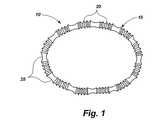
いくつかの図面を通して同じ部品に同じ符号が付されている図面を参照すると、移植部材本体15を含む例示的な移植部材10が図1に示されている。移植部材本体は、哺乳類である患者内の意図された自然の解剖学的な受容場所の解剖学的なニーズによって決定された形状及び寸法で設けられている。このような自然の解剖学的な受容場所は、図示はするが、制限は意図していない、心臓弁、胃と食道との接合部近傍の食道、肛門、その場所の寸法及び形状を変化させ、手術後の所望の寸法及び形状を維持することができる移植部材によって開放される機能不全をつくる哺乳類の体内の他の解剖学的な場所である。 Referring to the drawings in which like parts are numbered the same throughout the several views, an
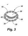
図1の移植部材10は、円形の移植本体15を含み、この円形の移植本体15は、狭い中間のネック部分を有するグロメット状の取り付け手段25と交互に介在する調整可能な波形部分20を備えている。図2及び図3で理解することができるように、移植部材15は、取り付け手段25の上又はそれを通して固定された縫合糸35のような固定手段によって心臓弁30の環状体に固定されることができる。波形部分20は、移植部材15の周囲が短くなるか、又は長くなると折り曲げられるか、折り戻される。元の場所での移植部材10の調整は、心臓弁30の全体寸法を減少させることができ、弁リーフレット40の接合を増大し、図2に示す形状から図3に示す形状まで形状を変化させる。 The
本発明の追加の例示的な実施例100は、図4及び図5に示されており、図4には、心臓110内の心臓の開放手術による切開部105が示されており、図5に心臓の切開部105が閉鎖されている状態が示されている。図4に示すように、本発明による例示的な調整可能な移植部材100は、移植部材本体115を含み、移植部材115は、僧帽弁125の環状体に固定することのできる取り付け手段120を有する。例示的な調整可能な移植部材100は、取り付けられた又は結合された調整ツール135によって制御される調整可能な手段130をさらに備えている。図5に示す心筋の切開部105の閉鎖の後、調整ツール135は、調整手段130に取り付けられ又は結合されたままであり、心臓110を通る生理学的な流れが再開した後、移植部材100の寸法及び形状は、影響を受けるが、胸の切開部は開放したままである。所望の形状及び機能が達成された後、調整ツール135は、調整手段130から離脱され、心筋の切開部105から引き抜かれる。本発明による種々の実施例において、調整手段130は、胸の切開部の閉鎖の次の調整のための調整ツール135によって、又は再導入によって保持することができるような構成であり、そのように配置される。 An additional
図4及び図5の移植部材100を使用するために、医師は、従来の態様で図4に示すような心臓110の開放手術による切開部105を形成する。調整ツール135の前端部に取り付けられた移植部材100は、切開部105を通して前進され、僧帽弁125の環状体に縫合される。調整ツール135が、操作、たとえば、調整手段130の構成によって回転され、調整手段が移植部材本体115のサイズを小さくするようにし、したがってそれが縫合されている下の僧帽弁125を適当な寸法にする。心筋切開部105は、図5に示すように閉鎖されることができるが、調整ツールは手術後の調整のために切開部を貫通したままである。 To use the
患者が「ポンプから離される」とき、心臓110を通過する正常な血液の流れが再開されるが、胸の切開部が閉鎖される前に、調整ツール135を操作することによって僧帽弁125の寸法の調整を行うことができる。 When the patient is “disengaged from the pump”, normal blood flow through the
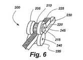
図6から図8は、前述したような移植部材100のような環状移植部材の周囲を調整するための例示的な調整手段200を示す。調整手段200は、ラックピニオン装置を含み、ラックピニオン装置は、ギヤ歯車210を有する第1のカム205及び係合カプラ215と第1の軸220上で回転する。この例において、第1のカム205は、第1のバンド230の1つ又は複数の面のギヤラック225に係合する。第1のバンド230は、第1のカム205と、第2のバンド245に結合された第2の軸240の上で回転する第2のカム235との間を通過する。図8に示すように、第1の軸及び第2の軸220、240は、第2のバンド245の端部に形成されたブラケット250によって適当な間隔を置いた関係で維持される。 6-8 illustrate an exemplary adjustment means 200 for adjusting the circumference of an annular implant member, such as the
調整手段200は、前述したタイプの中空の環状移植部材100内に設定されることが好ましいが、第1と第2のバンド230、245が同じ連続した環状構造の両端にあるスタンドアロン形状の調整手段を使用することが可能である。いずれの場合においても、調整手段200を含む移植部材の長さを調整するために、6角レンチのような工具が、第1のカム205の上の係合カプラ215に係合し、図7の矢印255によって示されるように反時計回りの方向に第1のカムを回転させる。第1のカム205の回転は、歯210がラック225を駆動し、第7図に示す矢印260によって示されるように、右に向かって第1のバンド230を移動させる。第1のバンドのこの運動は、環状移植部材の周囲を締め付ける。医師が不意に移植部材を強く締めすぎると、係合カプラ215の反対方向が移植部材を緩める。 The adjusting means 200 is preferably set in a hollow
本発明による種々の実施例において、第1及び第2のバンド230、245は、分離した構造であるか、同じ連続構造の両端であってもよい。このような実施例において、係合カプラ215に動きが付与されたとき、第1のカム205が回転し、ギヤ歯210をギヤラック225に係合させ、第1のバンド230を第2のバンド245に関して移動させ、移植部材の周囲を調整する。 In various embodiments according to the present invention, the first and
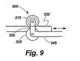
図9は、本発明による例示的な係合手段300のわずかに異なる形状を示しており、この場合、係合カプラはなく、ブラケット350が、第1のカム315と第2のカム320を接近して維持するために両側に設けられる。1つの提案された実施例において、ブラケットは、第1のバンド330を第2のバンド345に対して緊密に押し、摩擦によって固定された相対位置にバンドを保持するように緊密な公差で設計されている。他の提案された実施例において、ブラケット350は、カム315、320がカムの間に第1のバンド330を挿入するために離れるように弾性材料からつくられ、そのとき、摩擦によって固定された相対位置にバンド330、345を保持するために十分な力でカムは後方に引かれる。カム315、320の間に弾性取り付け構成を含む他の提案された実施例において、第1のバンド330の下縁及び第2のバンド345の上縁は、かみ合う摩擦的又は機械的表面を有し、それによって、カム315、320は、バンドの間の相対運動を可能にするために離れ、又は固定関係でバンドを一緒にクランプするために解放されるようにすることができる。 FIG. 9 shows a slightly different shape of an exemplary engagement means 300 according to the present invention, in which there is no engagement coupler and the
図10は、本発明による移植部材の例示的な取り付け手段400を示す。取り付け手段400は、たとえば、移植部材10の取り付け手段25の代わりに使用されることができる。取り付け手段400は、内腔420と取り付け面425とを画成する壁415を含むグロメット410の形態をとる。このような取り付け手段は、内腔420を貫通する移植部材本体とともに、及び取り付け面425の上で結ばれる縫合糸又はワイヤ又はそれを通して固定される固定装置とともに使用される。 FIG. 10 shows an exemplary attachment means 400 for an implant according to the present invention. The attachment means 400 can be used in place of the attachment means 25 of the
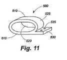
図11は、本発明による移植部材の取り付け手段500の他の実施例を示す。取り付け手段500は、たとえば、移植部材10の取り付け手段25の代わりに使用されることができる。図11は、内腔520、外面525及び取り付けタブ530を画成する壁515を含む中空の管又は管部材510の形態の取り付け手段500を示す。このような取り付け手段は、内腔520を貫通する移植部材本体とともに、及び取り付けタブ530の上で結ばれる縫合糸又はワイヤ又はそれを通して固定される固定装置とともに使用される。このような固定装置は、取り付けタブ530内に設けられた穴535を通して配置される。別の例として、中実の取り付けタブ530が設けられてもよく、固定装置が、中実のタブを貫通していてもよい。これらの取り付け手段の変形例は、縫合糸のない取り付けシステムに関連して使用されることができる。 FIG. 11 shows another embodiment of the implant mounting means 500 according to the present invention. The attachment means 500 can be used instead of the attachment means 25 of the
図12から図18は、本発明による皮下環状形成装置の他の実施例を示しており、この実施例において、移植部材/供給システム配列600は、ハウジング鞘部605(図12には示さず)、ハウジング鞘部605内に同軸的に摺動可能に取り付けられた作動カテーテル610と、作動カテーテル610内に同軸的に摺動可能に取り付けられたコアカテーテル615とを含む。コアカテーテルは、中央の内腔616(図13)を有する。作動カテーテル610及びコアカテーテル615は、丸い管状の構造体であるか、又は図13に示すように、作動及びコアカテーテルのいずれか又はその双方がハウジング鞘部605又は作動カテーテル610のいずれかの内腔内で1つ又は複数の往復動スロット622、624によって受けられるそれぞれ1つ又は複数のキー付隆起部618、620を備えていてもよい。このようなキー付き隆起部618、620は、使用中に望ましくない回転運動による不意の動きから内側内容物の制御を維持するためにこのような制限が望ましいならば、外側部材内での内側部材の内側の回転を制限する。 FIGS. 12-18 illustrate another embodiment of a subcutaneous annuloplasty device according to the present invention in which the implant /
移植部材/供給システム配列600は、コアカテーテル615の前端に遠位端625を含む。1つ又は複数の半径方向移植部材支持アーム630は、その遠位端625に隣接してコアカテーテル615に回転可能に又は屈曲可能に取り付けられたそれらの遠位端632を有する。半径移植部材支持アーム630の近位端634は、通常はコアカテーテル615に沿って伸びているが、コアカテーテルから離れるように外側に移動することができる。 The implant /
1つ又は複数の半径支持ストラット636は、作動カテーテル610の遠位端に回転可能に又は屈曲可能に取り付けられた近位端638を有する。各半径支持ストラット636の遠位端640は、対応する半径移植部材支持アーム630の中間点に回転可能に又は屈曲可能に取り付けられている。作動カテーテル610が、コアカテーテル615に対して前進するとき、半径支持ストラット636は、半径移植部材支持アーム630をコウモリ傘のように上方及び外側に押す。したがって、作動カテーテル610、コアカテーテル615、半径支持ストラット636、半径支持アーム630は組み合わされて展開コウモリ傘642を形成する。 One or more radial support struts 636 have a
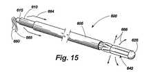
補綴移植部材645は、半径移植部材支持アーム630の近位端634に解放可能に取り付けられている。補綴移植部材645の周囲にそこから近位方向に複数の保持針646が伸びている。さらに、1つ又は複数の半径移植部材支持アーム630は、近位端が移植部材645に伸びているタッチダウン・センサ648を含む。例示的な実施例600のコアカテーテル615の中央内腔616(図13)を貫通し、遠位端625から近位端に間隔を置いて側方ポート650の外側(図12)に1つ又は複数の解放部材660があり、これは、供給システムから移植部材645を解放するように作用し、また、移植部材の展開寸法及び効果を調整するように作用する1つ又は複数の調整部材665がある。解放部材660及び調整部材665は、図14から図16で理解できるようにコアカテーテル615の近位端を貫通しているので、これらの部材は、医師によって直接又は間接的に器具として用いられるか、操作されることができる。供給インタフェイス670(図12、図16)は、この例において、展開傘642、解放部材660及び移植部材645の相互作動によって定義される。開示した実施例において、解放部材660は、移植部材645及び半径移植部材支持アーム630のレーザドリル穴を貫通し、次にコアカテーテル615の長さを通過する連続ループ内の縫合糸、ファイバ、又はワイヤである。このような実施例において、移植部材645は、近位端、患者の外側で解放部材660を切り離し、コアカテーテル610を通して解放部材660の自由端を引くことによって所望のときに供給システムから解放されることができる。 The
図14から図16は、移植部材/供給システム配列600の動作を示し、その動作において、補綴移植部材645の傘状の膨張がハウジング鞘部605、作動カテーテル610、及びコアカテーテル615の摺動運動によって達成される。まず、図14を参照すると、ハウジング鞘部605は、移植部材/供給システム配列600の心臓挿入のために作動カテーテル610及びコアカテーテル615の前端をカバーするために延びている。この開始位置から、ハウジング鞘部605は、矢印662によって示される方向に後退する。図15において、ハウジング鞘部605は、作動カテーテル610の前端及び折りたたまれた展開傘642を露出するために後退されている。作動カテーテル610は、この位置から、矢印664によって指示された方向に前進させられる。これは、矢印666によって指示される方向に展開傘を拡張させる。図16は、コアカテーテル615に対して作動カテーテル610の遠位端の動きによって生じる展開傘642の拡張を示す。移植部材645が配置された後、適当な寸法に調整され、ハウジング鞘部605は、矢印668によって示された方向に前進させられ、患者から装置を引き抜くために展開傘642を折りたたみ、カバーする。 FIGS. 14-16 illustrate the operation of the implant /
図17及び図18は、移植部材/供給システム配列600の半径移植部材支持アーム630及び半径支持ストラット636を示す概略図である。図17において、半径支持ストラット636が、作動カテーテル610への第1の回転可能な接続点670でその近位端に回転可能に取り付けられている。半径支持ストラット636は、対応する半径移植部材支持アーム630の中間点で第2の回転可能な接合点672で遠位端640に取り付けられている。半径移植部材支持アーム630は、コアカテーテル620に第3の回転可能な接合点674によって遠位端632に取り付けられている。図17は、閉鎖状態におけるアセンブリを示す。作動カテーテル610が、矢印676によって示されるようなコアカテーテル615の上に遠位方向に前進されるとき、矢印678によって示されるような第1の回転可能な接合部670、第2の回転可能な接合部672及び第3の回転可能な接合部674での動きによって半径支持ストラット636及び半径移植部材支持アーム630は延長される。この動きは、(図17及び図18には示さない)展開傘及び折りたたまれた移植部材を伸ばす効果を有し、図12から図16に関して前述したように係合及び移植の前に、その最も大きな半径方向の寸法を達成することを可能とする。 FIGS. 17 and 18 are schematic diagrams illustrating the radial
図19及び図20は、図12で前に示したタッチダウン・センサ648のさらなる詳細を示す。図19及び図20のタッチダウン・センサ648は、遠位部材680、中間部材682、及び近位部材684を含む。遠位部材680は、ばねによって取り付けられており、最大の変化時に近位部材684とのシームレス接合を達成するために中間部材682の上で摺動可能で、入れ子状の移動が可能である。タッチダウン・センサ648がその通常の状態にあるとき、ばねは、センサが図19に示す定位をとるように近位部材を伸ばす。移植部材645(図12)が、解剖学的な開口の周囲に対して配置されるとき、センサ648の近位部材684は、図20に示すように遠位部材680に対して押し付けられる。遠位部材680及び近位部材684は、鞘がカバーされるか、放射線不透過材料でカバーされることによって製造される。しかしながら、中間部材682は、このような放射線不透過材料で製造されず、カバーもされない。したがって、遠位部材680が休止しているとき、それは、近位部材684から完全に伸張し、露出された中間部材682によって表されたギャップは、放射線試験で見ることができる。しかしながら、遠位部材680が近位部材684と最大限接近するとき、このような放射線不透過ギャップは、放射線で見ることができず、タッチダウン・センサは、「起動」されたといえる。この実施例は、遠位カテーテル部材680の延長の度合いに関してタッチダウン・センサ684の位置の放射線監視を可能にする。図示したような本発明による実施例において、移植部材を僧帽弁環状体に展開するためにプロテーゼ装置のための供給システムが適当な位置に配置されることを確認するために1つ又は複数のタッチダウン検出器648は使用される。この解剖学的な構造が、蛍光透視法又は標準的なX線撮影法で直接識別できないとき、このような正確な位置決めは困難である。同時に、僧帽弁環状体の正確な位置決め及び係合は、適当な移植部材機能及び安全性にとって重要である。 19 and 20 show further details of the
本発明による実施例内のタッチダウン・センサは、テレスコープ、ばね負荷、前述した例のようなX線透過部材によって接合されたX線透過部材を含む多数の形態をとることができる。磁気共振影像法を使用する実施例において、本発明によるタッチダウン検出器は、同様のテレスコープ、ばね負荷配列の非金属部材によってはさまれた金属部材を使用することができる。他の実施例は、目で確認できるテレスコープを有するシステム、カラーコード又は直接、又は内視鏡観察が可能である手順のために他の目で見える特徴を有するばね負荷部材を含む。本発明による他のタッチダウン検出器の他の実施例は、十分な圧力の瞬間的な接触が電気回路を形成し、タッチダウン検出器の起動をオペレータに知らせるようにそれらの先端にマイクロスイッチを備えている。本発明による他のタッチダウン検出器は、移植する所望の場所に組織の独特の組織の品質を検出することができるラーメンレーザ(Rahmen laser)分光器又は他の分光分析技術を備えている。さらに、本発明による他の実施例は、所望の組織の所望の電気生理学的なインピーダンス、又は他の測定可能な品質が適当な移植について検出されるとき、検出し、オペレータに知らせることができる他の電気センサを含むタッチダウン検出器を含む。このような電気生理学的なタッチダウン検出器は、検出器が起動し、移植部材が取り付けのために適当な位置にあることをオペレータに知らせる視覚の信号、音声信号又は他の信号を生成する電気回路を含む。 Touchdown sensors in embodiments according to the present invention can take a number of forms, including telescopes, spring loads, and x-ray transmissive members joined by x-ray transmissive members such as those described above. In an embodiment using magnetic resonance imaging, the touchdown detector according to the present invention can use a similar telescope, a metal member sandwiched by non-metallic members of a spring loaded array. Other embodiments include a spring loaded member with a system having a visually observable telescope, color code or other visible feature for procedures that allow direct or endoscopic observation. Other embodiments of other touchdown detectors according to the present invention include microswitches at their tips so that momentary contact of sufficient pressure forms an electrical circuit and informs the operator of activation of the touchdown detector. I have. Other touchdown detectors according to the present invention include a Rahmen laser spectrometer or other spectroscopic technique that can detect the unique tissue quality of the tissue at the desired location for implantation. Furthermore, other embodiments according to the present invention can detect and inform the operator when the desired electrophysiological impedance of the desired tissue, or other measurable quality is detected for the appropriate implant. Including a touchdown detector including a plurality of electrical sensors. Such an electrophysiological touchdown detector is an electrical that generates a visual, audio or other signal that informs the operator that the detector is activated and the implant is in the proper position for attachment. Includes circuitry.
本発明による他の実施例において、前述したようなタッチダウン・センサについての必要性を解消するために、他の心臓内又は心臓外影像技術は、血管の超音波、核磁気共振、目視解剖学的位置決め装置、又は移植部材の適当な位置決めを確認するために他の影像技術を含むが、これに制限されない心臓内及び心臓外技術を使用することができる。 In other embodiments according to the present invention, other intracardiac or extracardiac imaging techniques include vascular ultrasound, nuclear magnetic resonance, visual anatomy to eliminate the need for touchdown sensors as described above. Intracardiac and extracardiac techniques can be used including, but not limited to, a mechanical positioning device or other imaging techniques to confirm proper positioning of the implant.
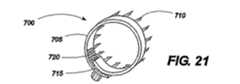
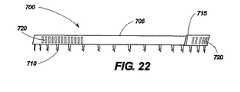
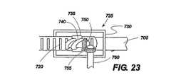
図21から図24は、本発明の1つの実施例による移植部材700を示している。この実施例において、移植部材本体705は、帯状で可撓性を有する。その十分な長さを通して、移植部材本体705は、一連の保持針710を備えており、この針710は、装置の配置、保持及び取り外しを容易にする方向を有する。また、移植部材本体705は、調整可能な部分715を備えており、この部分715は、この例において、一連の調整停止部720を備えている。調整停止部720は、スロット、穴、戻り止め、くぼみ、隆起部、歯、隆起部材、又は使用中移植部材700の測定される調整が可能になるように他の機械的な特徴を有する。図21から図24に示す実施例において、調整停止部720は、ギヤ付コネクタ725と係合する。図21は、それ自身が湾曲した移植部材本体705を示し、保持針710が外側に向かい、調整可能な部分715がギヤ付コネクタ725と係合しており、移植部材本体705内で内側に湾曲して閉鎖された丸い構造を形成している。図23は、例示的なギヤ付コネクタ725の詳細を示し、その中でハウジング730は、移植部材本体705に接続されている。ハウジング730は、機械的ウォーム740を含み、第2のギヤヘッド755とかみ合う第1のギヤヘッド750によって支持している。第2のギヤヘッド755は、調整ステム760に取り付けられ、この調整ステム760は、ネジ回し状の調整部材を受けるように機械加工されている。本発明による種々の実施例は、多数の形態の調整部材を必要とする。本例において、調整部材(図示せず)は、調整ステム760の受容スロットによって受けられるべき遠位端を有する細かく巻かれたワイヤとして提供される。調整部材の遠位端と調整ステム760の間の関係は、ネジ回し及びねじヘッドと機械的に同様であり、オペレータによって調整手段に付与されるねじれは、調整ステム760及び第2のギヤヘッド755を回転させ、第1のギヤヘッド750及びウォーム740の動きを可能にし、これは、ウォームが一連の調整頭部725と係合するとき、調整可能な移植部材715の動きを形成する。調整可能な部分715の余分な長さは、バンドスロット735を貫通し(図23)、バンドを閉鎖した移植部材本体705の内側に同心的に移動させることができるようにする。この実施例の調整部材は、展開傘が後退し、引かれた後、所定の位置に保持されるように構成されることができる。調整部材の遠位端と調整ステム760との間の接続は、簡単な摩擦接続であるか、機械的なキー/スロット形成であるか、磁気的又は電気的に維持されていてもよい。 21-24 show an
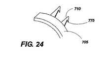
さらに図21に示すように、例示的な実施例は、移植部材本体705の外周に取り付けられる単一方向性の保持針710を使用する。展開時に移植部材本体の回転運動が所望の組織に接触して保持針710に係合するか、解放するように、保持針710は一貫して移植部本体705に対して正接方向を向いている。保持針710のこの位置決めによって移植部材700をその軸線に回転させることでオペレータが移植部材700をねじ込むことができるようにし、保持針710を隣接する組織内に係合させる。図24に示すように、保持針710は、周囲の組織を把持する(魚釣りフックと同様に)端子フック775の作動により、移植部材700を反対方向に回転させることなく移植部材700を回転させることによって保持針710に係合するとき、組織を円滑に通過することのできるように端部に端子フックをさらに備えることもできる。端子フック775は、移植部材700の周囲の組織への配置を確実にする。 As further shown in FIG. 21, the exemplary embodiment uses a
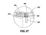
図25から図27は、本発明によって考えられる移植部材800の他の実施例を示している。移植部材800は、バンド805(図27)を含むが、前記例の保持針は、外側織物移植部材鞘810に関しては省略された。織物鞘部810は、所望の位置に解剖学的な組織に縫合されるか、固定される。移植部材本体800の周囲は、図23に示される帯状移植部材配列のギヤコネクタと同様ギヤコネクタを通して調整される。さらに詳細には、バンドの上の調整ステップ820は、取り付けられた第1のギヤヘッド850によって機械的ウォーム840と係合する。第1のギヤヘッド850は、第2のギヤヘッド855とかみ合う。第2のギヤヘッド855は、調整ステム860に取り付けられ、調整ステム860は、ねじ回し状の調整ステム部材を受けるように機械加工される。 FIGS. 25-27 show another embodiment of an
図28は、虚血性環状膨張症及び僧帽弁逆流を有する患者内に移植部材645を位置決めするための移植部材/供給システム配列600の使用方法の例を示す。周囲の動脈のアクセスは、従来のカットダウン、動脈貫通、又は標準のアクセス技術を介して得られる。動脈システムへのアクセスが得られた後、ガイドワイヤの配置が実行され、蛍光透視法、超音波、三次元超音波、磁気共振、又は他のリアルタイム影像技術を使用して心臓900への血管内のアクセスが得られる。ガイドワイヤ、展開装置及び移植部材は、左心室905、次に左心房910へのこれまでの方法で大動脈弁を通過される。この時点において、オペレータは、ハウジング鞘部605を後退させ、したがって、折りたたまれた展開傘642及び移植部材645の鞘をはずす。展開傘642は、作動カテーテルの遠位運動によって、広がり、半径方向の支持アームとストラットとを完全に広げる。この時点では、タッチダウン検出器648は中実の構造には接触せず、影像システムで見ることができるX線ギャップによって完全に拡張される。展開傘が拡張すると、アセンブリ全体が僧帽弁915の領域に対して後方に引かれる。少なくとも2つのタッチダウン検出器648は、本発明による好ましい実施例において使用される。すべてのタッチダウン検出器がそれらの中間の非不透過、中間部材の消失を示すとき、したがって作動されるとき、展開傘は、僧帽弁環状体/動脈組織の領域の中実組織と接触していなければならず、さらに移植部材の展開と調整が進行される。しかしながら、1つのタッチダウン・センサが作動せず、X線ギャップが存在する場合、その装置は、適切には配置されず、さらなる展開の前に再び配置されなければならない。したがって、タッチダウン・センサ・システムは、本発明による供給システムによって補綴装置の展開及び調整を補助することができる。適切に配置されると、オペレータは、作動カテーテルを前述した時計方向又は反時計方向に回転させて僧帽弁環状/心房組織領域の組織内の移植部材上に保持針を係合させる。再配置が必要であれば、反対の動きによって、環状/心房組織から保持針を離脱させ、適当な位置決めのためにタッチダウン検出器を使用して再位置決めを実行することができる。ひとたびしっかりと配置されると、調整部材は、所望の度合いの環状の低減を達成するために作動される。リアルタイムのトランス食道超音波検査、血管内超音波検査、心臓内超音波検査、又は僧帽弁機能を評価するための他のモダリティが使用され、僧帽弁の機能への治療の生理学的な効果を評価してもよく、追加の調整が実行されてもよい。所望の結果が達成されると、解放部材が展開傘から移植部材を取り外すために使用される。オペレータは、作動カテーテルを後退させ、ハウジング鞘部を延長させ、展開傘を収縮させ、心臓と血管組織から装置の円滑で非外傷性の引き抜きのために部品をカバーする。 FIG. 28 illustrates an example of how the implant member /
所望ならば、調整部材は、カテーテル部品が生理学的な調整のために引き抜かれた後、残されてもよい。本発明による他の実施例において、カテーテルをベースにした調整部材は、皮下又は他の経路を通して連続的に再び挿入されることができる。このような調整部材は、オペレータによって、舵取り可能なように操作可能であり、移植部材内に含まれる調整可能な機構を有する調整部材の結合が可能になるよう磁気、電気、電磁気又はレーザによって案内するシステムを備えていてもよい。他の実施例において、調整機構は、移植された電気機械モータ又は他のシステムによって駆動され、これらのシステムは、電気フラックス又は他の遠隔操作による皮下又は経皮的な方法によって遠隔的に制御されることができる。 If desired, the adjustment member may be left after the catheter part is withdrawn for physiological adjustment. In another embodiment according to the present invention, the catheter-based adjustment member can be continuously reinserted through the subcutaneous or other route. Such an adjustment member can be steered by an operator and guided by magnetism, electricity, electromagnetics or lasers to allow the adjustment member having an adjustable mechanism contained within the implant member to be coupled. You may have the system to do. In other embodiments, the adjustment mechanism is driven by an implanted electromechanical motor or other system, which is remotely controlled by electrical flux or other remotely controlled subcutaneous or transcutaneous methods. Can.
肺動脈弁治療の場合、初期のカテーテルのアクセスは、周囲又は中央の静脈を通して達成される。肺動脈弁へのアクセスは、中央の静脈のアクセスが右心房、三尖弁、右心室を横切り、及び連続して肺動脈弁に到達することによって達成されるとき、弁の下から達成される。 In the case of pulmonary valve treatment, initial catheter access is achieved through the surrounding or central vein. Access to the pulmonary valve is achieved from below the valve when central venous access is achieved by traversing the right atrium, tricuspid valve, right ventricle, and continuously reaching the pulmonary valve.
本発明による他の実施例において、左心房へのカテーテルのアクセスは、中央又は周囲の血管のカニューレ挿入で達成されることができ、それによって右心房へのアクセスが達成される。標準の房のトランスセプタル法は、医原病(iatrogenic)心房中隔欠損症(ASD)引き起こされることよって左心房へアクセスするために使用されることができる。このような状況において、僧帽弁は、実施例1に説明した従来のアクセスとは反対に弁の上から接近されることができる。移植部材及び反転した展開傘は、前述したものと同じ治療技術により、僧帽弁環状体の心房の観点において移植部材の配置によって使用されることができる。医原病ASDは、標準の装置及び方法を使用して閉鎖されることができる。また、大動脈弁へのアクセスは、同様の従来の態様において心房のアクセスを介して大動脈弁の上から達成することができる。 In other embodiments according to the present invention, catheter access to the left atrium can be achieved by cannulation of the central or surrounding blood vessels, thereby achieving access to the right atrium. Standard atrial transceptal methods can be used to access the left atrium by causing an iatrogenic atrial septal defect (ASD). In such a situation, the mitral valve can be accessed over the valve as opposed to the conventional access described in Example 1. The graft member and inverted deployment umbrella can be used by placement of the graft member in terms of the mitral annulus atria with the same therapeutic techniques as described above. The iatrogenic ASD can be closed using standard equipment and methods. Also, access to the aortic valve can be achieved from above the aortic valve via atrial access in a similar conventional manner.
本発明による調整可能な移植部材及び方法の他の実施例は、食道胃逆流病(GERD)のような胃腸内の不全を含み、この状態において、胃と食道(GE)との接合が、胃の内容物の食道への逆流を防止するために適切な括約筋トーンを欠損しており、従来の胸焼け又は酸の逆流を生じる。これは不快なだけでなく、予備ガン障害(Barrett’s食道)の進行又はGE接合における食道の腺ガンを招き、時間が経過すると、食道の下部に障害を生じる。GE接合の外科的な治療は、歴史的にNissenのファンドプリケーションによって達成されてきた。手術の手順は一般に良好な結果を有する。しかしながら、Nissenの手順は、通常、麻酔及び入院を必要とする。本発明による装置及び方法を使用することによって、調整可能な移植部材は、入院の必要性を解消し、医院又は胃腸病学者のオフィスで実行される。図29及び図30を参照すると、移植部材645を有する傘展開装置600は、内視鏡1000の案内のもとに患者の口、食道1005を通り、胃1010に入り、ここで展開装置600は、カラーコード又は目視ギャップを有する移植部材645及びタッチダウン検出器648の拡張によって開放される。次にタッチダウン検出器は、直接的な内視鏡の制御のもと、すべてのタッチダウン検出器648が視覚的に起動されるまで、胃と食道の接合1015の周りで胃の上に係合される。移植部材は、胃壁1020に取り付けられ、移植部材645及び調整部材を残して、傘642は解放され引き抜かれる。次に、移植部材は、所望の効果が達成されるまで、すなわち、患者の症状、食道のpH監視、影像の研究、又は他の診断手段のいずれかによって最小限の酸の逆流が達成されるまで調整される。患者に、ガスの膨張の症状、治療が困難であり、患者がげっぷをすることができない胃と食道との接合部の共通の複雑さがあるときには、移植部材は、さらに所望の効果が得られるまで緩められることができる。 Other embodiments of adjustable implants and methods according to the present invention include gastrointestinal insufficiency such as esophageal reflux disease (GERD), in which the connection between the stomach and the esophagus (GE) It lacks the proper sphincter tone to prevent reflux of its contents to the esophagus, resulting in conventional heartburn or acid reflux. This is not only uncomfortable, but also leads to the progression of preliminary cancer damage (Barrett's esophagus) or esophageal adenocarcinoma in the GE junction, which over time causes damage to the lower esophagus. Surgical treatment of GE junctions has historically been accomplished by Nissen funding. Surgical procedures generally have good results. However, the Nissen procedure usually requires anesthesia and hospitalization. By using the device and method according to the present invention, the adjustable implant eliminates the need for hospitalization and is performed at the clinic or gastroenterologist's office. 29 and 30, an
本発明によって考えられる種々の実施例において、移植部材本体は、直線、曲線、円形、卵型、多角形、又はその組み合わせである。本発明によって考えられる種々の実施例において、移植部材は、身体内のオリフィス又は内腔の均一又は非均一な調整を提供することができる。さらに、移植部材本体は、自然の受容的な解剖学的な場所を完全に閉鎖するか、又は自然の受容的な解剖学的な場所の一部のみを包囲することを妨げられない形態で供給されることができる。本発明の他の実施例において、移植部材本体は、管状又は中空の構造を形成する。本発明の1つの実施例において、本体は、さらに外側部材、内側部材及び選択的な取り付け部材を有する構造であってもよい。このような実施例において、移植部材本体の外側部材は、移植部材のカバーとして機能していてもよく、自然の受容的な解剖学的な場所の組織の内成長及び生物学的な調整を容易にし、促進するように構成される。このような実施例における外側部材は、Dacron、PTFE、可鍛金属、他の生物学的に互換性のある材料又は成型、織られた、又は不織構造の生物学的に互換性のある材料の組み合わせから製造される。このような実施例において、外側部材は内側部材を包囲するように作用する。この実施例において、内側部材は、調整機構によって作動されるとき、制限された態様で外側部材の形状及び/又は寸法を変更することができることを意味する調整を提供する。 In various embodiments contemplated by the present invention, the implant member body is straight, curved, circular, oval, polygonal, or a combination thereof. In various embodiments contemplated by the present invention, the implant can provide uniform or non-uniform adjustment of the orifice or lumen within the body. Further, the implant member body is supplied in a form that does not prevent the natural receptive anatomical site from being completely closed or surrounding only a portion of the natural receptive anatomical location. Can be done. In other embodiments of the present invention, the implant body forms a tubular or hollow structure. In one embodiment of the present invention, the body may be a structure further comprising an outer member, an inner member, and an optional attachment member. In such embodiments, the outer member of the implant member body may function as a cover for the implant member, facilitating tissue ingrowth and biological adjustment in natural receptive anatomical locations. And configured to promote. The outer member in such embodiments is Dacron, PTFE, malleable metal, other biologically compatible materials or molded, woven or non-woven biologically compatible materials. Manufactured from a combination of In such an embodiment, the outer member acts to surround the inner member. In this embodiment, the inner member provides an adjustment meaning that the shape and / or dimensions of the outer member can be changed in a limited manner when actuated by an adjustment mechanism.
本発明による他の実施例において、調整手段は、外側部材の外側に配置されるか、その内側に組み込まれる。本発明によるさらに他の実施例において、移植部材本体は、前記調整手段をカバーする別個の外側部材のない隣接手段からなることができる。 In another embodiment according to the invention, the adjusting means are arranged outside or incorporated inside the outer member. In yet another embodiment according to the present invention, the implant member body may consist of adjacent means without a separate outer member covering the adjusting means.
本発明による種々の実施例において、調整手段は、ねじ又はねじのない機構を含み、かつ適当な寸法が決定された後、所望の寸法及び所望の位置の慎重な調整及び保持を可能にするために、ねじ又はウォームねじ、摩擦機構、摩擦デタント機構、歯付き機構、ラチェット機構、ラックピニオン機構、又は他の装置と係合される機構を含む。 In various embodiments in accordance with the present invention, the adjustment means includes a screw or screwless mechanism and allows for the careful adjustment and retention of the desired dimensions and desired position after the appropriate dimensions have been determined. Include a screw or worm screw, a friction mechanism, a friction detent mechanism, a toothed mechanism, a ratchet mechanism, a rack and pinion mechanism, or a mechanism engaged with other devices.
本発明による他の機構において、調整手段は、スネア、パースストリング状の機構を含み、その場合、外科医又は他のオペレータによってワイヤ又はファイバに付与される張力又は動きの変化時に自然の解剖学的な受容的な場所への移植部材装置の解剖学的及び/又は生物学的な効果を与えることができる縫合糸、バンド、ワイヤ、又は他のファイバ構造、ブレイド又は非ブレイド、モノフィラメント又はマルチフィラメントを含む。このような調整手段は、種々の実施例における円形、又は非円形の構造として提供される。張力又は運動の変化は、移植部材の寸法及び/又は形状を変化させることができる。 In other mechanisms according to the present invention, the adjustment means includes a snare, parse string-like mechanism, in which case the natural anatomical structure changes upon the tension or movement applied to the wire or fiber by the surgeon or other operator. Includes sutures, bands, wires, or other fiber structures, braided or unbraided, monofilaments or multifilaments that can provide the anatomical and / or biological effects of the implant device to a receptive location . Such adjustment means are provided as circular or non-circular structures in various embodiments. Changes in tension or motion can change the size and / or shape of the implant.
本発明による種々の実施例において、調整手段は、金属、プラスティック、合成、天然、生物学的又は他の生物学的に互換性のある材料又はその組み合わせであってもよい。このような調整手段は、さらに、延伸、又は他の成型技術、機械加工、又は織物によって製造されることができる。さらに本発明の種々の実施例において、調整手段は、円滑であるか、又はスロット、又はビード、隆起部又は他の円滑な織物面を含んでいてもよい。 In various embodiments according to the present invention, the adjustment means may be metal, plastic, synthetic, natural, biological or other biologically compatible materials or combinations thereof. Such adjustment means can further be produced by stretching or other molding techniques, machining or textiles. Further, in various embodiments of the present invention, the adjustment means may be smooth or may include slots, or beads, ridges or other smooth fabric surfaces.
本発明の種々の実施例において、移植部材本体は、自然の受容場所への移植部材の取り付けを容易にするために、グロメット又は開口又は他の取り付け部材のような1つ又は複数の取り付け部材を備えていてもよい。他の実施例において、移植部材本体は、自然の受容場所において移植部材を固定する縫合糸のない機械的な手段を可能にする機械的組織接合システムに取り付けるか又は組み込むことができる。さらに他の実施例において、縫合糸又は他の取り付け手段は、自然の受容場所に移植部材を固定するために、移植部材本体の周り又はそれを通して縫合糸又は他の取り付け手段を固定することができる。本発明の他の実施例において、移植部材本体を自然の受容場所に固定する機械的な手段は、フィブリン、又は他の生物学的に互換性のある組織接着剤又は同様の接着剤の使用によって増加されるか、置換される。 In various embodiments of the present invention, the implant member body includes one or more attachment members such as grommets or openings or other attachment members to facilitate attachment of the implant member to a natural receiving location. You may have. In other embodiments, the implant member body can be attached to or incorporated into a mechanical tissue bonding system that allows a sutureless mechanical means of securing the implant in a natural receiving location. In still other embodiments, the suture or other attachment means can secure the suture or other attachment means around or through the implant member body to secure the implant member in its natural receiving location. . In another embodiment of the present invention, the mechanical means of securing the implant member body in its natural receiving location is through the use of fibrin, or other biologically compatible tissue adhesive or similar adhesive. Increased or replaced.
本発明による他の種々の実施例において、調整可能な移植部材は、病気の進行がこのような周囲又は他の寸法を狭くするか、又は制限するオリフィス、孔、内腔又は交差連絡の周囲又は他の寸法を調整可能に拡大するか、維持するために使用することができる。 In other various embodiments according to the present invention, the adjustable implant may be a perimeter of an orifice, hole, lumen or cross-connector where disease progression narrows or limits such or other dimensions or Other dimensions can be used to adjustably expand or maintain.
本発明による種々の実施例において、調整機構は、調整手段の寸法及び/又は位置における所望の変更を達成するために調整手段と相互作用するために提供されることができる。このような調整機構は、1つ又は複数のねじ、ウォームねじ配列、ローラ、ギヤ、摩擦停止部、摩擦デタントシステム、ラチェット、ラックピニオン機構、マイクロ電子機械システム、他の機械的電子機械的装置又はそのいくつかの組み合わせを含んでいてもよい。 In various embodiments according to the present invention, an adjustment mechanism can be provided to interact with the adjustment means to achieve a desired change in the size and / or position of the adjustment means. Such adjustment mechanisms may include one or more screws, worm screw arrays, rollers, gears, friction stops, friction detent systems, ratchets, rack and pinion mechanisms, microelectromechanical systems, other mechanical electromechanical devices or Some combinations thereof may be included.
本発明によって考えられるようなある実施例において、調整ツールは、調整機構に永久的に又は取り外し可能に取り付けられ、運動を調整機構に付与し、次に調整手段に付与して自然の受容場所に移植部材の解剖学的な効果を増減するために配置されることができる。 In certain embodiments, such as contemplated by the present invention, the adjustment tool is permanently or removably attached to the adjustment mechanism to impart motion to the adjustment mechanism and then to the adjustment means to provide a natural receiving location. Can be arranged to increase or decrease the anatomical effects of the implant.
本発明による他の実施例において、関連する電子制御回路を有する1つ又は複数のマイクロ電子機構モータシステムを有するマイクロモータ配列が調整手段として提供され、電磁波による信号搬送を通して遠隔制御によって作動されるか、又は前記マイクロモータ配列に永久的に又は遠隔的に取り付けられる電気導管線を通る直接的な回路によって作動されることができる。 In another embodiment according to the present invention, a micromotor arrangement having one or more microelectronic motor systems with associated electronic control circuits is provided as a regulating means and is operated by remote control through signal transport by electromagnetic waves Or by a direct circuit through an electrical conduit that is permanently or remotely attached to the micromotor array.
本発明による種々の他の実施例において、調整機構は、自然の受容場所及びそれが属する身体的な組織への最適な所望の解剖学的な、及び/又は生物学的な効果の達成時に選択的な位置において、調整手段の位置を維持するために配置された固定機構を備えている。他の実施例において、使用される調整手段の性質によって特別な固定機構は必要ない。 In various other embodiments according to the present invention, the adjustment mechanism is selected upon achievement of an optimal desired anatomical and / or biological effect on the natural receiving location and the physical tissue to which it belongs. A fixing mechanism arranged to maintain the position of the adjusting means at a general position. In other embodiments, no special locking mechanism is required depending on the nature of the adjustment means used.
本発明による他の実施例によれば、調整手段及び/又は外側部材の構造は、紫外線のような選択された波長の電磁波に露出されたときに硬化することができる柔軟な合成材料であってもよい。このような実施例において、所望の電磁波に露出することは、外科医による移植部材へのこのような放射の外部からの供給によって、前記外側部材内に配置され、適当な外部放射源に接続された光ファイバ搬送体を使用して、外側の移植部材内のこのような放射の内側供給によって達成される。このような光ファイバ搬送体は、適当な放射露出及び前記調整手段の硬化の後に、外側の移植部材から全部又は一部においてそれらの除去のために配置されることができる。 According to another embodiment of the present invention, the structure of the adjusting means and / or the outer member is a flexible synthetic material that can be cured when exposed to an electromagnetic wave of a selected wavelength, such as ultraviolet light. Also good. In such embodiments, exposure to the desired electromagnetic wave is placed within the outer member and connected to a suitable external radiation source by external supply of such radiation to the implant by the surgeon. This is accomplished by the inner delivery of such radiation in the outer implant using a fiber optic carrier. Such fiber optic carriers can be arranged for their removal in whole or in part from the outer implant after appropriate radiation exposure and curing of the adjusting means.
本発明は、哺乳類の体内の血液、他の体液、栄養分、半固体、固体、又は廃棄物のための通路を形成する組織の解剖学的な構造及び/又は生理的な効果を選択的に変えるために調整可能な移植部材装置を使用する方法を提供する。調整可能な移植部材のこのような使用のための種々の実施例は、制限はされないが、蛍光透視法、超音波、磁気共振影像、又は他の影像技術、冠動脈洞、又は食道壁のような組織構造を通る前記移植部材の経皮又は血管経由での配置を通しての自然の受容場所での前記調整可能な移植部材の開放外科手術又は、上述した技術のいくつかの組み合わせを使用する方法を含む。本発明によって考えられる種々の実施例において、調整可能な移植部材は、ビーティング又は非ビーティング心臓外科手術手順又は胃腸内の内視鏡的に又は経皮的にトランス心房、トランス心室、トランス動脈、トランス静脈(すなわち、肺静脈を介して)自然の受容解剖学的場所の所定の位置に配置されるか、固定される。 The present invention selectively alters the anatomical structure and / or physiological effects of tissue forming a passage for blood, other bodily fluids, nutrients, semi-solids, solids, or waste in a mammalian body A method of using an adjustable implant member device is provided. Various examples for such use of adjustable implants include, but are not limited to, fluoroscopy, ultrasound, magnetic resonance imaging, or other imaging techniques, such as coronary sinus or esophageal wall Including methods of using open surgery of the adjustable implant at a natural receiving location through percutaneous or vascular placement of the implant through a tissue structure or some combination of the techniques described above. . In various embodiments contemplated by the present invention, the adjustable implant may be a beating or non-beating cardiac surgical procedure or endoscopically or percutaneously in the gastrointestinal trans-atrium, trans-ventricle, trans-artery, trans- The vein (ie, via the pulmonary vein) is placed or fixed in place in the natural receiving anatomy.
さらに、調整可能な移植部材装置の使用の他の方法は、若い患者の自然な受容場所の成長を許容するために必要な前記移植部材装置を受ける解剖学的な構造の寸法又は受容患者の生理学的なニーズの他の変化の手術後の周期的な調整を提供する。 In addition, other methods of use of the adjustable implant device include the size of the anatomical structure that receives the implant device required to allow the young patient's natural receiving site to grow or the recipient patient's physiology. Provide post-operative periodic adjustment of other changes in specific needs.
調整可能な移植部材の調整及びこの明細書に開示したような使用のための方法は、所望の効果を達成するために必要とされる調整の性質の評価を提供するために外科医又は診断ツールのオペレータによっての使用を考える。このような、診断ツールは、制限はされないが、トランス食道超音波心臓検査、超音波心臓検査、超音波診断、血管内超音波、磁気共振によって統合された目視解剖学的ポジショニングシステム又は他の影像技術、内視鏡、メディアスチノスコピィ、腹腔鏡、ソラコスコピィ、X線撮影法、蛍光透視法、磁気共振影像法と統合された目視解剖学的位置決め装置、コンピュータによるトモグラフィック影像、血管内流れセンサ、熱センサ又は影像、遠隔化学スペクトル分析、又は他の影像、量的質的な分析システムを含む。 A method for adjustment of an adjustable implant and use as disclosed herein provides a method for the surgeon or diagnostic tool to provide an assessment of the nature of the adjustment required to achieve the desired effect. Consider use by operators. Such diagnostic tools include, but are not limited to, trans-esophageal echocardiography, ultrasound cardiography, ultrasound diagnosis, intravascular ultrasound, visual anatomical positioning system or other image integrated by magnetic resonance Technology, Endoscope, Media stinoscope, Laparoscope, Soracoscopy, X-ray photography, Fluoroscopy, Visual anatomical positioning device integrated with magnetic resonance imaging, Computerized tomographic image, Intravascular flow sensor , Thermal sensor or image, remote chemical spectral analysis, or other image, quantitative and qualitative analysis system.
1つの側面において、本発明の移植部材/供給システムは、折りたたみ可能、圧縮可能、又は膨張可能な移植部材及び補綴移植部材のような供給インタフェイスを含み、この補綴移植部材は、折りたたみ可能、圧縮可能、又は非膨張可能な状態で所望な解剖学的な受容場所に補綴移植部材を供給し、所望の解剖学的な受容場所でユーザによってこのような補綴移植部材の制御された伸張又は膨張及び物理的な取り付けを可能にすることができる。このようなシステムは、供給システム及び補綴移植部材を、トロカール、鞘部を通して、セルディング技術、針を通して皮下的に、又は自然の体のオリフィス、身体内の空所、又は領域を内視鏡によって、所望の解剖学的な受容場所に外科医又はオペレータによって操作されて導入され、ここで、供給システム及び補綴移植部材は、展開するために操作によって拡張される。所望のときは、本発明の移植部材/供給システムは、それがひとたび所望の解剖学的受容場所に取り付けられるとき、ユーザが、補綴移植部材の寸法又は形状を調整することができるようにする。本発明による供給システムは、補綴移植部材を有するインタフェイスから取り外し、オペレータによって解剖学的場所から取り外すことができる。供給システム及び補綴移植部材は、哺乳類である患者内の意図された自然の受容解剖学的場所の解剖学的なニーズによって決定された形状及び寸法で設けられている。このような自然の受容解剖学的場所は、心臓弁、胃と食道との接合部近傍の食道、肛門、又はその場所の寸法及び形状を変化することができ、手術の後、所望の寸法及び形状を維持することができる移植部材によって解放されることができる障害を形成する哺乳類の身体内の他の解剖学的場所である。 In one aspect, the implant / delivery system of the present invention includes a supply interface such as a collapsible, compressible, or expandable implant and a prosthetic implant, the prosthetic implant being collapsible, compressible Providing a prosthetic implant in a desired or non-expandable state to a desired anatomical receiving location and controlled expansion or expansion of such prosthetic implant by the user at the desired anatomical receiving location and Physical attachment can be possible. Such systems can be used to deliver delivery systems and prosthetic implants through trocars, sheaths, celling techniques, subcutaneously through needles, or natural body orifices, cavities, or regions within the body by endoscope. , Operated and introduced by a surgeon or operator at the desired anatomical receiving location, where the delivery system and prosthetic implant are expanded by operation to deploy. When desired, the implant / delivery system of the present invention allows the user to adjust the size or shape of the prosthetic implant once it is attached to the desired anatomical receiving location. The delivery system according to the present invention can be removed from the interface with the prosthetic implant and removed from the anatomical location by the operator. The delivery system and prosthetic implant are provided in a shape and size determined by the anatomical needs of the intended natural receiving anatomical location within the mammalian patient. Such natural receptive anatomical locations can change the size and shape of the heart valve, the esophagus near the junction of the stomach and esophagus, the anus, or the location, and after surgery the desired dimensions and Other anatomical locations within the mammalian body that form obstacles that can be released by an implant that can maintain shape.
本発明によって考えられる種々の実施例において、供給システムは、カテーテル、ワイヤ、フィラメント、ロッド、管、内視鏡、又は、血管、オリフィス、又は組織内腔のような解剖学的な通路を通して、又は腹腔を通して、又は胸部を通して切開部、貫通孔、トロカールを通して、所望の受容解剖学的場所に到達することができる他の機構である。本発明の種々の実施例において、供給システムは、オペレータによって舵取り可能である。さらに、供給システムは、所望の受容解剖学的場所に補綴移植部材を保持し、搬送する供給インタフェイスを有する。このような、供給インタフェイスは、膨張、再形成、所望の受容解剖学的な場所でこのような補綴移植部材の独立した膨張、拡大を可能にすることができる。さらに、このような供給インタフェイスは、前記移植部材がそれ自身所望の受容解剖学的場所に到達したとき、補綴移植部材の膨張、拡大寸法、形状、又は生理学的効果を調整するために作動可能な手段を提供することがきる。本発明による種々の実施例によれば、このような調整は、移植部材が配置される手順の間、連続した時間で実行される。特定の適用例の特定の物理学的なニーズに依存して、供給インタフェイス及び関連する補綴移植部材は、直線、湾曲している形状、円形、螺旋形状、管状、卵形、多角形、又はそのいくつかの組み合わせであってもよい。本発明の他の実施例において、補綴移植部材は、中実構造であり、他の実施例において、補綴移植部材は、管状、複合体、又は他の中空の構造である。本発明の1つの実施例において、補綴移植部材は、さらに、外側部材、内側部材、及び選択的な取り付け部材を有する構造である。このような実施例において、補綴移植部材の外側部材は、移植部材のカバーとして作用し、自然の受容解剖学的場所への組織の内成長及び生物学的な統合を容易にし促進するように構成される。このような実施例の外側部材は、Dacron、PTFE、可鍛金属、他の生物学的に互換性のある材料又は成型、織られた、又は不織構造の生物学的に互換性のある材料の組み合わせから製造される。このような実施例の外側部材は内側部材を包囲するように作用する。この実施例において、内側部材は、調整機構によって作動されるとき、制限された態様で外側部材の形状及び/又は寸法を変更することができることを意味する調整を提供する。 In various embodiments contemplated by the present invention, the delivery system may be through a catheter, wire, filament, rod, tube, endoscope, or anatomical passage such as a blood vessel, orifice, or tissue lumen, or Other mechanisms that can reach the desired receiving anatomical location through the abdominal cavity or through the chest, through the incision, through hole, trocar. In various embodiments of the present invention, the delivery system can be steered by an operator. In addition, the delivery system has a delivery interface that holds and conveys the prosthetic implant in the desired receiving anatomical location. Such a delivery interface can allow for expansion, remodeling, and independent expansion and expansion of such prosthetic implants at the desired receiving anatomical location. Further, such a delivery interface is operable to adjust the expansion, enlarged size, shape, or physiological effects of the prosthetic implant when the implant has itself reached the desired receiving anatomical location. Can provide a simple means. According to various embodiments in accordance with the present invention, such adjustment is performed at successive times during the procedure in which the implant is placed. Depending on the specific physical needs of a particular application, the delivery interface and associated prosthetic implant can be straight, curved, circular, helical, tubular, oval, polygonal, or There may be some combinations thereof. In other embodiments of the invention, the prosthetic implant is a solid structure, and in other embodiments the prosthetic implant is a tubular, composite, or other hollow structure. In one embodiment of the invention, the prosthetic implant is a structure further comprising an outer member, an inner member, and an optional attachment member. In such embodiments, the outer member of the prosthetic implant serves as a cover for the implant and is configured to facilitate and facilitate tissue ingrowth and biological integration into the natural receiving anatomical location. Is done. The outer member of such an embodiment can be Dacron, PTFE, malleable metal, other biologically compatible materials or molded, woven or non-woven biologically compatible materials. Manufactured from a combination of The outer member of such an embodiment acts to surround the inner member. In this embodiment, the inner member provides an adjustment meaning that the shape and / or dimensions of the outer member can be changed in a limited manner when actuated by an adjustment mechanism.
本発明によるある実施例によれば、調整可能な内側又は外側部材の少なくともいくつかの部分は、このような変形が、直腸の失禁、又は子宮脱の治療のような機能的に価値のある設定において弁、括約筋、オリフィス、又は内腔に可変の人工の筋肉調の部材を与えるために弾性的である。 According to certain embodiments according to the present invention, at least some portions of the adjustable inner or outer member may be configured such that such deformation is a functionally valuable setting such as treatment of rectal incontinence or uterine prolapse. In order to provide a variable artificial muscle-like member to the valve, sphincter, orifice, or lumen.
本発明による種々の実施例において、供給インタフェイスは、それがオペレータによって配置されると、補綴移植部材の調整中に元の場所で自然の解剖学的な受容場所に補綴移植部材を途中に保持し搬送するための取り付け手段を有する。このような取り付け手段は、補綴移植部材の所望の配置及び調整が達成されると補綴移植部材の供給インタフェイスからの離脱を可能にするために操作的に反転される。 In various embodiments according to the present invention, the delivery interface retains the prosthetic implant halfway in its natural location at the original location during adjustment of the prosthetic implant when it is positioned by the operator. And has attachment means for conveying. Such attachment means are operatively inverted to allow removal of the prosthetic implant from the delivery interface once the desired placement and adjustment of the prosthetic implant is achieved.
最後に、好ましい実施例が例示として開示され、他の変形例が、特許請求の範囲及び製品から逸脱せずに当業者によって生じることは理解すべきである。 Finally, it is to be understood that the preferred embodiment is disclosed by way of example and that other variations will occur to those skilled in the art without departing from the scope of the claims and product.
Claims (23)
Translated fromJapanese前記環状リングを解剖学的オリフィス又は内腔の周りの組織に固定することができる手段と、
第1の周囲から第2の周囲に前記環状リングの周囲の調整を可能にするために前記環状リングに関連する手段と、
前記リングを前記第1の周囲に維持し、前記環状リングが前記第2の周囲に調整されたとき、前記環状リングを前記第2の周囲に維持するために前記環状リングに関連する手段とを含み、
前記解剖学的オリフィス又は内腔の前記周囲は、前記第1の周囲から前記第2の周囲に前記環状リングの前記周囲を調整することによって調整されることができる、解剖学的オリフィス又は内腔の内周を制御するための移植可能な装置。An annular ring,
Means capable of securing said annular ring to tissue around an anatomical orifice or lumen;
Means associated with the annular ring to allow adjustment of the circumference of the annular ring from a first circumference to a second circumference;
Means associated with the annular ring to maintain the ring in the first circumference and maintain the annular ring in the second circumference when the annular ring is adjusted to the second circumference; Including
The circumference of the anatomical orifice or lumen can be adjusted by adjusting the circumference of the annular ring from the first circumference to the second circumference. Implantable device for controlling the inner circumference of the device.
前記環状リングを解剖学的なオリフィス又は内腔の周りの組織に固定することができる前記手段は前記管を含み、前記管は、縫合糸が前記管を貫通し、前記下の組織を通ることができるように十分に柔らかく、
第1の周囲から第2の周囲への前記環状リングの前記周囲の調整を可能にするための前記環状リングと関連する前記手段は、前記波形部分を含み、
前記リングを前記第1の周囲に維持し、前記環状リングが前記第2の周囲に調整されたとき、前記環状リングを前記第2の周囲に維持するために前記環状リングに関連する手段は、前記環状のリングが所定の形状に配置されたとき、十分に硬い波形部分を含み、前記選択された解剖学的なオリフィス又は内腔で正常な解剖学的な力が加えられたとき、前記所定の形状のままになる傾向がある請求項1に記載の移植可能な装置。The annular ring includes a hollow tube formed in an annulus, the tube having smooth and corrugated portions alternately spaced around its circumference;
The means capable of securing the annular ring to tissue around an anatomical orifice or lumen includes the tube that passes through the tube and through the underlying tissue. Soft enough to be able to
The means associated with the annular ring for allowing adjustment of the circumference of the annular ring from a first circumference to a second circumference comprises the corrugated portion;
Means associated with the annular ring to maintain the ring in the first circumference and, when the annular ring is adjusted to the second circumference, to maintain the annular ring in the second circumference; When the annular ring is placed in a predetermined shape, it includes a sufficiently stiff corrugated portion, and when a normal anatomical force is applied at the selected anatomical orifice or lumen, the predetermined ring The implantable device of claim 1, which tends to remain in the shape of
前記環状リングを、解剖学的なオリフィス又は内腔の周りの組織に固定することができる前記手段は、縫合糸を狭くなっている周囲の前記部分で前記管の周りに下の組織を通して通過されるように狭くなった周囲部分を有する前記管を含み、
第1の周囲から第2の周囲に前記環状リングの周囲の調整を可能にするために前記環状リングに関連する前記手段は、前記波形部分を含み、
前記リングを前記第1の周囲に維持し、前記環状リングが前記第2の周囲に調整されたとき、前記環状リングを前記第2の周囲に維持するために前記環状リングに関連する手段は、前記環状のリングが所定の形状に配置されたとき、十分に硬い波形部分を含み、前記選択された解剖学的なオリフィス又は内腔で正常な解剖学的な力が加えられたとき、前記所定の形状のままになる傾向がある請求項1に記載の移植可能な装置。The annular ring includes a hollow tube formed in an annular shape, and the tube has smooth portions and corrugated portions alternately arranged around the periphery,
The means capable of securing the annular ring to the tissue around the anatomical orifice or lumen is passed through the underlying tissue around the tube at the portion of the circumference around which the suture is narrowed. Including said tube having a peripheral portion narrowed to
The means associated with the annular ring to allow adjustment of the circumference of the annular ring from a first circumference to a second circumference comprises the corrugated portion;
Means associated with the annular ring to maintain the ring in the first circumference and, when the annular ring is adjusted to the second circumference, to maintain the annular ring in the second circumference; When the annular ring is placed in a predetermined shape, it includes a sufficiently stiff corrugated portion, and when a normal anatomical force is applied at the selected anatomical orifice or lumen, the predetermined ring The implantable device of claim 1, which tends to remain in the shape of
前記環状リングの少なくとも一部に形成された歯と、
前記環状リングの前記歯に係合するギヤとを有し、前記ギヤ及び前記歯は、前記歯車を回転することによって、第1の周囲から第2の周囲に前記環状リングの周囲を調整するために前記環状リングの第1の端部と第2の端部との間の相対運動を行うように配置されている請求項1に記載の移植可能な装置。Said means associated with said annular ring to allow adjustment of the circumference of said annular ring from a first circumference to a second circumference;
Teeth formed on at least a portion of the annular ring;
A gear engaging the teeth of the annular ring, the gear and the teeth for adjusting the circumference of the annular ring from a first circumference to a second circumference by rotating the gear. The implantable device of claim 1, wherein the implantable device is arranged to provide relative movement between a first end and a second end of the annular ring.
ウォームギヤと、
前記ウォームギヤの回転が、第1の周囲から第2の周囲に前記環状リングの周囲を調整するために前記環状リングの第1の端部と第2の端部との間の相対運動を行うように前記ウォームギヤに係合するために前記環状リングの第1の端部と動作的に関連する手段とを含む請求項1に記載の移植可能な装置。Said means associated with said annular ring to allow adjustment of the circumference of said annular ring from a first circumference to a second circumference;
Worm gear,
The rotation of the worm gear causes relative movement between the first and second ends of the annular ring to adjust the circumference of the annular ring from a first circumference to a second circumference. 2. The implantable device of claim 1 including means operatively associated with the first end of the annular ring for engaging the worm gear.
Applications Claiming Priority (5)
| Application Number | Priority Date | Filing Date | Title |
|---|---|---|---|
| US40684102P | 2002-08-29 | 2002-08-29 | |
| US44400503P | 2003-01-31 | 2003-01-31 | |
| US44738303P | 2003-02-14 | 2003-02-14 | |
| US46243503P | 2003-04-12 | 2003-04-12 | |
| PCT/US2003/027278WO2004019816A2 (en) | 2002-08-29 | 2003-08-29 | Implantable devices for controlling the internal circumference of an anatomic orifice or lumen |
Publications (2)
| Publication Number | Publication Date |
|---|---|
| JP2005537067Atrue JP2005537067A (en) | 2005-12-08 |
| JP4316503B2 JP4316503B2 (en) | 2009-08-19 |
Family
ID=31982587
Family Applications (1)
| Application Number | Title | Priority Date | Filing Date |
|---|---|---|---|
| JP2004531996AExpired - Fee RelatedJP4316503B2 (en) | 2002-08-29 | 2003-08-29 | Implantable device for controlling an anatomical orifice or lumen |
Country Status (16)
| Country | Link |
|---|---|
| US (8) | US7297150B2 (en) |
| EP (2) | EP1531762B1 (en) |
| JP (1) | JP4316503B2 (en) |
| KR (1) | KR101050626B1 (en) |
| CN (1) | CN1684644B (en) |
| AT (1) | ATE464028T1 (en) |
| AU (2) | AU2003265850A1 (en) |
| CA (1) | CA2497042A1 (en) |
| DE (1) | DE60332117D1 (en) |
| ES (1) | ES2349952T3 (en) |
| IL (1) | IL167133A (en) |
| MX (1) | MXPA05002284A (en) |
| NO (1) | NO20051147L (en) |
| PT (1) | PT1531762E (en) |
| RU (1) | RU2005108673A (en) |
| WO (2) | WO2004019816A2 (en) |
Cited By (14)
| Publication number | Priority date | Publication date | Assignee | Title |
|---|---|---|---|---|
| JP2007517596A (en)* | 2004-01-09 | 2007-07-05 | カーディオキネティックス・インコーポレイテッド | Ventricular compartment |
| JP2009537278A (en)* | 2006-05-19 | 2009-10-29 | ミトラル・ソリューションズ・インコーポレイテッド | Implantable device for controlling the size and shape of anatomical structures or lumens |
| JP2010514537A (en)* | 2007-01-03 | 2010-05-06 | ミトラル・ソリューションズ・インコーポレイテッド | Implantable device for controlling the size and shape of an anatomical structure or lumen |
| JP2010515488A (en)* | 2007-01-08 | 2010-05-13 | ミリピード リミテッド ライアビリティー カンパニー | Reconstruction of cardiac features |
| JP2010516333A (en)* | 2007-01-19 | 2010-05-20 | ガイデッド デリバリー システムズ, インコーポレイテッド | Methods and devices for cardiac tissue repair |
| JP2012515624A (en)* | 2009-01-22 | 2012-07-12 | セント・ジュード・メディカル,カーディオロジー・ディヴィジョン,インコーポレイテッド | Postoperative adjustment tool, minimally invasive mounting device, and adjustable tricuspid valve ring |
| US8673001B2 (en) | 2002-08-29 | 2014-03-18 | StJude Medical, Cardiology Division, Inc. | Methods for controlling the internal circumference of an anatomic orifice or lumen |
| US8758372B2 (en) | 2002-08-29 | 2014-06-24 | St. Jude Medical, Cardiology Division, Inc. | Implantable devices for controlling the size and shape of an anatomical structure or lumen |
| US8864823B2 (en) | 2005-03-25 | 2014-10-21 | StJude Medical, Cardiology Division, Inc. | Methods and apparatus for controlling the internal circumference of an anatomic orifice or lumen |
| US9180005B1 (en) | 2014-07-17 | 2015-11-10 | Millipede, Inc. | Adjustable endolumenal mitral valve ring |
| US9492276B2 (en) | 2005-03-25 | 2016-11-15 | St. Jude Medical, Cardiology Division, Inc. | Methods and apparatus for controlling the internal circumference of an anatomic orifice or lumen |
| US9795480B2 (en) | 2010-08-24 | 2017-10-24 | Millipede, Inc. | Reconfiguring tissue features of a heart annulus |
| JP2024091655A (en)* | 2017-04-18 | 2024-07-05 | エドワーズ ライフサイエンシーズ コーポレイション | HEART VALVE SEALING DEVICE AND ITS DELIVERY DEVICE - Patent application |
| JP2024547055A (en)* | 2021-12-20 | 2024-12-26 | ボストン サイエンティフィック サイムド,インコーポレイテッド | Devices, systems and methods for placing anchors for artificial chordae - Patents.com |
Families Citing this family (685)
| Publication number | Priority date | Publication date | Assignee | Title |
|---|---|---|---|---|
| US7670383B1 (en)* | 2004-05-04 | 2010-03-02 | Biomet Manufacturing Corp. | Pubic catch |
| US7722678B2 (en)* | 1993-11-01 | 2010-05-25 | Biomet Manufacturing Corp. | Intramedullary compliant fixation |
| US7476254B2 (en)* | 1993-11-01 | 2009-01-13 | Biomet Manufacturing Corporation | Compliant fixation for pelvis |
| US6077214A (en) | 1998-07-29 | 2000-06-20 | Myocor, Inc. | Stress reduction apparatus and method |
| EP2133030A1 (en)* | 1997-06-27 | 2009-12-16 | The Trustees of Columbia University of the City of New York | Method and apparatus for circulatory valve repair |
| FR2768324B1 (en) | 1997-09-12 | 1999-12-10 | Jacques Seguin | SURGICAL INSTRUMENT FOR PERCUTANEOUSLY FIXING TWO AREAS OF SOFT TISSUE, NORMALLY MUTUALLY REMOTE, TO ONE ANOTHER |
| US8216256B2 (en) | 1999-04-09 | 2012-07-10 | Evalve, Inc. | Detachment mechanism for implantable fixation devices |
| AU770243B2 (en) | 1999-04-09 | 2004-02-19 | Evalve, Inc. | Methods and apparatus for cardiac valve repair |
| US6752813B2 (en) | 1999-04-09 | 2004-06-22 | Evalve, Inc. | Methods and devices for capturing and fixing leaflets in valve repair |
| US10327743B2 (en) | 1999-04-09 | 2019-06-25 | Evalve, Inc. | Device and methods for endoscopic annuloplasty |
| US7811296B2 (en) | 1999-04-09 | 2010-10-12 | Evalve, Inc. | Fixation devices for variation in engagement of tissue |
| US20040044350A1 (en) | 1999-04-09 | 2004-03-04 | Evalve, Inc. | Steerable access sheath and methods of use |
| US7226467B2 (en) | 1999-04-09 | 2007-06-05 | Evalve, Inc. | Fixation device delivery catheter, systems and methods of use |
| US6997951B2 (en) | 1999-06-30 | 2006-02-14 | Edwards Lifesciences Ag | Method and device for treatment of mitral insufficiency |
| US7582051B2 (en)* | 2005-06-10 | 2009-09-01 | Cardiokinetix, Inc. | Peripheral seal for a ventricular partitioning device |
| US8529430B2 (en) | 2002-08-01 | 2013-09-10 | Cardiokinetix, Inc. | Therapeutic methods and devices following myocardial infarction |
| US8500795B2 (en) | 1999-08-09 | 2013-08-06 | Cardiokinetix, Inc. | Retrievable devices for improving cardiac function |
| US9694121B2 (en) | 1999-08-09 | 2017-07-04 | Cardiokinetix, Inc. | Systems and methods for improving cardiac function |
| US8388672B2 (en) | 1999-08-09 | 2013-03-05 | Cardiokinetix, Inc. | System for improving cardiac function by sealing a partitioning membrane within a ventricle |
| US10307147B2 (en) | 1999-08-09 | 2019-06-04 | Edwards Lifesciences Corporation | System for improving cardiac function by sealing a partitioning membrane within a ventricle |
| EP1113497A3 (en)* | 1999-12-29 | 2006-01-25 | Texas Instruments Incorporated | Semiconductor package with conductor impedance selected during assembly |
| US7296577B2 (en) | 2000-01-31 | 2007-11-20 | Edwards Lifescience Ag | Transluminal mitral annuloplasty with active anchoring |
| US9332993B2 (en) | 2004-08-05 | 2016-05-10 | Cardiokinetix, Inc. | Devices and methods for delivering an endocardial device |
| US9078660B2 (en) | 2000-08-09 | 2015-07-14 | Cardiokinetix, Inc. | Devices and methods for delivering an endocardial device |
| US10064696B2 (en) | 2000-08-09 | 2018-09-04 | Edwards Lifesciences Corporation | Devices and methods for delivering an endocardial device |
| US9332992B2 (en) | 2004-08-05 | 2016-05-10 | Cardiokinetix, Inc. | Method for making a laminar ventricular partitioning device |
| EP1309289A2 (en) | 2000-08-18 | 2003-05-14 | Atritech, Inc. | Expandable implant devices for filtering blood flow from atrial appendages |
| US6602288B1 (en)* | 2000-10-05 | 2003-08-05 | Edwards Lifesciences Corporation | Minimally-invasive annuloplasty repair segment delivery template, system and method of use |
| US7033373B2 (en) | 2000-11-03 | 2006-04-25 | Satiety, Inc. | Method and device for use in minimally invasive placement of space-occupying intragastric devices |
| US6800090B2 (en)* | 2001-05-14 | 2004-10-05 | Cardiac Dimensions, Inc. | Mitral valve therapy device, system and method |
| ITMI20011012A1 (en) | 2001-05-17 | 2002-11-17 | Ottavio Alfieri | ANNULAR PROSTHESIS FOR MITRAL VALVE |
| US7935145B2 (en) | 2001-05-17 | 2011-05-03 | Edwards Lifesciences Corporation | Annuloplasty ring for ischemic mitral valve insuffuciency |
| US7083629B2 (en) | 2001-05-30 | 2006-08-01 | Satiety, Inc. | Overtube apparatus for insertion into a body |
| US6558400B2 (en) | 2001-05-30 | 2003-05-06 | Satiety, Inc. | Obesity treatment tools and methods |
| US7097665B2 (en) | 2003-01-16 | 2006-08-29 | Synecor, Llc | Positioning tools and methods for implanting medical devices |
| US6845776B2 (en) | 2001-08-27 | 2005-01-25 | Richard S. Stack | Satiation devices and methods |
| CN101810521B (en) | 2001-08-27 | 2015-05-13 | 辛尼科有限责任公司 | Satiation devices and methods |
| US6675809B2 (en) | 2001-08-27 | 2004-01-13 | Richard S. Stack | Satiation devices and methods |
| US6908482B2 (en) | 2001-08-28 | 2005-06-21 | Edwards Lifesciences Corporation | Three-dimensional annuloplasty ring and template |
| US6824562B2 (en)* | 2002-05-08 | 2004-11-30 | Cardiac Dimensions, Inc. | Body lumen device anchor, device and assembly |
| US7311729B2 (en)* | 2002-01-30 | 2007-12-25 | Cardiac Dimensions, Inc. | Device and method for modifying the shape of a body organ |
| US6949122B2 (en) | 2001-11-01 | 2005-09-27 | Cardiac Dimensions, Inc. | Focused compression mitral valve device and method |
| US7635387B2 (en) | 2001-11-01 | 2009-12-22 | Cardiac Dimensions, Inc. | Adjustable height focal tissue deflector |
| US6805710B2 (en)* | 2001-11-13 | 2004-10-19 | Edwards Lifesciences Corporation | Mitral valve annuloplasty ring for molding left ventricle geometry |
| US6575971B2 (en)* | 2001-11-15 | 2003-06-10 | Quantum Cor, Inc. | Cardiac valve leaflet stapler device and methods thereof |
| US7179282B2 (en)* | 2001-12-05 | 2007-02-20 | Cardiac Dimensions, Inc. | Device and method for modifying the shape of a body organ |
| US6793673B2 (en) | 2002-12-26 | 2004-09-21 | Cardiac Dimensions, Inc. | System and method to effect mitral valve annulus of a heart |
| US6976995B2 (en) | 2002-01-30 | 2005-12-20 | Cardiac Dimensions, Inc. | Fixed length anchor and pull mitral valve device and method |
| US20050209690A1 (en)* | 2002-01-30 | 2005-09-22 | Mathis Mark L | Body lumen shaping device with cardiac leads |
| US7004958B2 (en)* | 2002-03-06 | 2006-02-28 | Cardiac Dimensions, Inc. | Transvenous staples, assembly and method for mitral valve repair |
| US6797001B2 (en)* | 2002-03-11 | 2004-09-28 | Cardiac Dimensions, Inc. | Device, assembly and method for mitral valve repair |
| US7146984B2 (en) | 2002-04-08 | 2006-12-12 | Synecor, Llc | Method and apparatus for modifying the exit orifice of a satiation pouch |
| US7695427B2 (en) | 2002-04-26 | 2010-04-13 | Torax Medical, Inc. | Methods and apparatus for treating body tissue sphincters and the like |
| US7445010B2 (en)* | 2003-01-29 | 2008-11-04 | Torax Medical, Inc. | Use of magnetic implants to treat issue structures |
| CA2877641C (en) | 2002-05-08 | 2017-01-17 | Cardiac Dimensions Pty. Ltd. | Device and method for modifying the shape of a body organ |
| US7510560B2 (en)* | 2002-06-20 | 2009-03-31 | Tyco Healthcare Group Lp | Method and apparatus for anastomosis including an anchoring sleeve |
| US7608103B2 (en)* | 2002-07-08 | 2009-10-27 | Edwards Lifesciences Corporation | Mitral valve annuloplasty ring having a posterior bow |
| US6746460B2 (en) | 2002-08-07 | 2004-06-08 | Satiety, Inc. | Intra-gastric fastening devices |
| US7214233B2 (en) | 2002-08-30 | 2007-05-08 | Satiety, Inc. | Methods and devices for maintaining a space occupying device in a relatively fixed location within a stomach |
| US7033384B2 (en) | 2002-08-30 | 2006-04-25 | Satiety, Inc. | Stented anchoring of gastric space-occupying devices |
| US8001971B2 (en)* | 2002-09-06 | 2011-08-23 | Koninklijke Philips Electronics N.V. | Devices, systems, and methods for stabilization or fixation of magnetic force devices used in or on a body |
| US10383755B2 (en) | 2002-09-09 | 2019-08-20 | Brian Kelleher | Device and method for endoluminal therapy |
| AU2003270549A1 (en)* | 2002-09-09 | 2004-03-29 | Brian Kelleher | Device and method for endoluminal therapy |
| US7229428B2 (en) | 2002-10-23 | 2007-06-12 | Satiety, Inc. | Method and device for use in endoscopic organ procedures |
| US7220237B2 (en) | 2002-10-23 | 2007-05-22 | Satiety, Inc. | Method and device for use in endoscopic organ procedures |
| US6656194B1 (en) | 2002-11-05 | 2003-12-02 | Satiety, Inc. | Magnetic anchoring devices |
| US20040133147A1 (en)* | 2002-11-06 | 2004-07-08 | Woo Sang Hoon | Intestinal bypass device to treat obesity |
| US7112219B2 (en) | 2002-11-12 | 2006-09-26 | Myocor, Inc. | Devices and methods for heart valve treatment |
| US7695446B2 (en) | 2002-12-02 | 2010-04-13 | Gi Dynamics, Inc. | Methods of treatment using a bariatric sleeve |
| WO2004049982A2 (en) | 2002-12-02 | 2004-06-17 | Gi Dynamics, Inc. | Bariatric sleeve |
| US7678068B2 (en) | 2002-12-02 | 2010-03-16 | Gi Dynamics, Inc. | Atraumatic delivery devices |
| US7766973B2 (en) | 2005-01-19 | 2010-08-03 | Gi Dynamics, Inc. | Eversion resistant sleeves |
| US7608114B2 (en) | 2002-12-02 | 2009-10-27 | Gi Dynamics, Inc. | Bariatric sleeve |
| US7025791B2 (en)* | 2002-12-02 | 2006-04-11 | Gi Dynamics, Inc. | Bariatric sleeve |
| US7316708B2 (en) | 2002-12-05 | 2008-01-08 | Cardiac Dimensions, Inc. | Medical device delivery system |
| US7837729B2 (en) | 2002-12-05 | 2010-11-23 | Cardiac Dimensions, Inc. | Percutaneous mitral valve annuloplasty delivery system |
| US20040133240A1 (en)* | 2003-01-07 | 2004-07-08 | Cardiac Dimensions, Inc. | Electrotherapy system, device, and method for treatment of cardiac valve dysfunction |
| US20040143342A1 (en)* | 2003-01-16 | 2004-07-22 | Stack Richard S. | Satiation pouches and methods of use |
| US7314485B2 (en) | 2003-02-03 | 2008-01-01 | Cardiac Dimensions, Inc. | Mitral valve device using conditioned shape memory alloy |
| ATE422858T1 (en)* | 2003-03-28 | 2009-03-15 | Gi Dynamics Inc | ANTI-OBESITY DEVICES |
| US7175638B2 (en) | 2003-04-16 | 2007-02-13 | Satiety, Inc. | Method and devices for modifying the function of a body organ |
| US20040220654A1 (en) | 2003-05-02 | 2004-11-04 | Cardiac Dimensions, Inc. | Device and method for modifying the shape of a body organ |
| US10631871B2 (en) | 2003-05-19 | 2020-04-28 | Evalve, Inc. | Fixation devices, systems and methods for engaging tissue |
| US7351259B2 (en)* | 2003-06-05 | 2008-04-01 | Cardiac Dimensions, Inc. | Device, system and method to affect the mitral valve annulus of a heart |
| US7887582B2 (en) | 2003-06-05 | 2011-02-15 | Cardiac Dimensions, Inc. | Device and method for modifying the shape of a body organ |
| US20060161251A1 (en)* | 2003-06-30 | 2006-07-20 | Shaw David P | Cuffs for medical applications |
| EP1646332B1 (en) | 2003-07-18 | 2015-06-17 | Edwards Lifesciences AG | Remotely activated mitral annuloplasty system |
| US7621948B2 (en)* | 2003-07-21 | 2009-11-24 | The Trustees Of The University Of Pennsylvania | Percutaneous heart valve |
| US8021421B2 (en)* | 2003-08-22 | 2011-09-20 | Medtronic, Inc. | Prosthesis heart valve fixturing device |
| US8206456B2 (en) | 2003-10-10 | 2012-06-26 | Barosense, Inc. | Restrictive and/or obstructive implant system for inducing weight loss |
| US20050247320A1 (en) | 2003-10-10 | 2005-11-10 | Stack Richard S | Devices and methods for retaining a gastro-esophageal implant |
| US7914543B2 (en) | 2003-10-14 | 2011-03-29 | Satiety, Inc. | Single fold device for tissue fixation |
| US7097650B2 (en) | 2003-10-14 | 2006-08-29 | Satiety, Inc. | System for tissue approximation and fixation |
| US20060184242A1 (en)* | 2003-10-20 | 2006-08-17 | Samuel Lichtenstein | Method and apparatus for percutaneous reduction of anterior-posterior diameter of mitral valve |
| AU2004305450B2 (en) | 2003-12-09 | 2009-01-08 | Gi Dynamics, Inc. | Intestinal sleeve |
| US8057420B2 (en) | 2003-12-09 | 2011-11-15 | Gi Dynamics, Inc. | Gastrointestinal implant with drawstring |
| US20060212042A1 (en)* | 2005-03-17 | 2006-09-21 | Lamport Ronald B | Removal and repositioning device |
| US9526616B2 (en) | 2003-12-19 | 2016-12-27 | Cardiac Dimensions Pty. Ltd. | Mitral valve annuloplasty device with twisted anchor |
| US7794496B2 (en) | 2003-12-19 | 2010-09-14 | Cardiac Dimensions, Inc. | Tissue shaping device with integral connector and crimp |
| US7837728B2 (en) | 2003-12-19 | 2010-11-23 | Cardiac Dimensions, Inc. | Reduced length tissue shaping device |
| US7329279B2 (en) | 2003-12-23 | 2008-02-12 | Sadra Medical, Inc. | Methods and apparatus for endovascularly replacing a patient's heart valve |
| US8287584B2 (en) | 2005-11-14 | 2012-10-16 | Sadra Medical, Inc. | Medical implant deployment tool |
| US8343213B2 (en) | 2003-12-23 | 2013-01-01 | Sadra Medical, Inc. | Leaflet engagement elements and methods for use thereof |
| US8579962B2 (en) | 2003-12-23 | 2013-11-12 | Sadra Medical, Inc. | Methods and apparatus for performing valvuloplasty |
| US20050137687A1 (en) | 2003-12-23 | 2005-06-23 | Sadra Medical | Heart valve anchor and method |
| US9526609B2 (en) | 2003-12-23 | 2016-12-27 | Boston Scientific Scimed, Inc. | Methods and apparatus for endovascularly replacing a patient's heart valve |
| EP2529699B1 (en) | 2003-12-23 | 2014-01-29 | Sadra Medical, Inc. | Repositionable heart valve |
| US8840663B2 (en) | 2003-12-23 | 2014-09-23 | Sadra Medical, Inc. | Repositionable heart valve method |
| US8603160B2 (en) | 2003-12-23 | 2013-12-10 | Sadra Medical, Inc. | Method of using a retrievable heart valve anchor with a sheath |
| US7381219B2 (en) | 2003-12-23 | 2008-06-03 | Sadra Medical, Inc. | Low profile heart valve and delivery system |
| US20120041550A1 (en) | 2003-12-23 | 2012-02-16 | Sadra Medical, Inc. | Methods and Apparatus for Endovascular Heart Valve Replacement Comprising Tissue Grasping Elements |
| US7445631B2 (en) | 2003-12-23 | 2008-11-04 | Sadra Medical, Inc. | Methods and apparatus for endovascularly replacing a patient's heart valve |
| US7780725B2 (en) | 2004-06-16 | 2010-08-24 | Sadra Medical, Inc. | Everting heart valve |
| US20050137694A1 (en) | 2003-12-23 | 2005-06-23 | Haug Ulrich R. | Methods and apparatus for endovascularly replacing a patient's heart valve |
| US7959666B2 (en) | 2003-12-23 | 2011-06-14 | Sadra Medical, Inc. | Methods and apparatus for endovascularly replacing a heart valve |
| US8182528B2 (en) | 2003-12-23 | 2012-05-22 | Sadra Medical, Inc. | Locking heart valve anchor |
| US11278398B2 (en) | 2003-12-23 | 2022-03-22 | Boston Scientific Scimed, Inc. | Methods and apparatus for endovascular heart valve replacement comprising tissue grasping elements |
| US9005273B2 (en)* | 2003-12-23 | 2015-04-14 | Sadra Medical, Inc. | Assessing the location and performance of replacement heart valves |
| US8828078B2 (en) | 2003-12-23 | 2014-09-09 | Sadra Medical, Inc. | Methods and apparatus for endovascular heart valve replacement comprising tissue grasping elements |
| US20050149072A1 (en)* | 2003-12-31 | 2005-07-07 | Devries Robert B. | Devices and methods for tissue invagination |
| US20050177176A1 (en) | 2004-02-05 | 2005-08-11 | Craig Gerbi | Single-fold system for tissue approximation and fixation |
| CA2556228C (en) | 2004-02-13 | 2014-05-13 | Satiety, Inc. | Methods for reducing hollow organ volume |
| MXPA06009971A (en) | 2004-02-27 | 2007-08-08 | Satiety Inc | Methods and devices for reducing hollow organ volume. |
| ITTO20040135A1 (en) | 2004-03-03 | 2004-06-03 | Sorin Biomedica Cardio Spa | CARDIAC VALVE PROSTHESIS |
| US8628547B2 (en) | 2004-03-09 | 2014-01-14 | Ethicon Endo-Surgery, Inc. | Devices and methods for placement of partitions within a hollow body organ |
| US9028511B2 (en) | 2004-03-09 | 2015-05-12 | Ethicon Endo-Surgery, Inc. | Devices and methods for placement of partitions within a hollow body organ |
| US8252009B2 (en) | 2004-03-09 | 2012-08-28 | Ethicon Endo-Surgery, Inc. | Devices and methods for placement of partitions within a hollow body organ |
| US8449560B2 (en) | 2004-03-09 | 2013-05-28 | Satiety, Inc. | Devices and methods for placement of partitions within a hollow body organ |
| US7942927B2 (en) | 2004-03-15 | 2011-05-17 | Baker Medical Research Institute | Treating valve failure |
| AU2005231323B2 (en) | 2004-03-26 | 2011-03-31 | Ethicon Endo-Surgery, Inc | Systems and methods for treating obesity |
| US7654985B2 (en)* | 2004-03-30 | 2010-02-02 | Given Imaging Ltd. | Controlled detachment of intra-luminal medical device |
| US7993397B2 (en) | 2004-04-05 | 2011-08-09 | Edwards Lifesciences Ag | Remotely adjustable coronary sinus implant |
| JP4225237B2 (en)* | 2004-04-21 | 2009-02-18 | セイコーエプソン株式会社 | ORGANIC EL DEVICE, METHOD FOR MANUFACTURING ORGANIC EL DEVICE, AND ELECTRONIC DEVICE |
| WO2005105003A1 (en) | 2004-04-26 | 2005-11-10 | Synecor, Llc | Restrictive and/or obstructive implant for inducing weight loss |
| JP5222552B2 (en)* | 2004-04-30 | 2013-06-26 | ミトラル・ソリューションズ・インコーポレイテッド | Methods and devices for modulation of heart valve function |
| US8048166B2 (en)* | 2004-05-04 | 2011-11-01 | Biomet Manufacturing Corp. | Method and apparatus for constructing a modular acetabulum |
| US7938856B2 (en)* | 2004-05-14 | 2011-05-10 | St. Jude Medical, Inc. | Heart valve annuloplasty prosthesis sewing cuffs and methods of making same |
| JP4774048B2 (en) | 2004-05-14 | 2011-09-14 | エヴァルヴ インコーポレイテッド | Locking mechanism of fixing device engaged with tissue and tissue engaging method |
| WO2005112832A1 (en)* | 2004-05-14 | 2005-12-01 | St. Jude Medical, Inc. | Systems and methods for holding annuloplasty rings |
| US7452376B2 (en)* | 2004-05-14 | 2008-11-18 | St. Jude Medical, Inc. | Flexible, non-planar annuloplasty rings |
| US7212423B2 (en)* | 2004-05-31 | 2007-05-01 | Intel Corporation | Memory agent core clock aligned to lane |
| US20050278022A1 (en)* | 2004-06-14 | 2005-12-15 | St. Jude Medical, Inc. | Annuloplasty prostheses with improved anchoring structures, and related methods |
| US7377941B2 (en) | 2004-06-29 | 2008-05-27 | Micardia Corporation | Adjustable cardiac valve implant with selective dimensional adjustment |
| US20080183285A1 (en)* | 2004-06-29 | 2008-07-31 | Micardia Corporation | Adjustable cardiac valve implant with selective dimensional adjustment |
| US7955357B2 (en) | 2004-07-02 | 2011-06-07 | Ellipse Technologies, Inc. | Expandable rod system to treat scoliosis and method of using the same |
| US20080288060A1 (en)* | 2004-07-06 | 2008-11-20 | Baker Medical Research Institute | Treating Valvular Insufficiency |
| ATE506042T1 (en) | 2004-07-09 | 2011-05-15 | Gi Dynamics Inc | DEVICES FOR PLACEMENT OF A GASTROINTESTINAL SLEEVE |
| US20060015178A1 (en)* | 2004-07-15 | 2006-01-19 | Shahram Moaddeb | Implants and methods for reshaping heart valves |
| EP1799145B1 (en) | 2004-09-17 | 2016-12-21 | GI Dynamics, Inc. | Gastrointestinal anchor |
| WO2006037073A2 (en) | 2004-09-27 | 2006-04-06 | Evalve, Inc. | Methods and devices for tissue grasping and assessment |
| US8052592B2 (en) | 2005-09-27 | 2011-11-08 | Evalve, Inc. | Methods and devices for tissue grasping and assessment |
| NZ554495A (en) | 2004-10-15 | 2010-09-30 | Bfkw Llc | Bariatric device and method with lumen exerting force on eosophagus or stomach areas |
| US7833257B2 (en)* | 2004-11-12 | 2010-11-16 | Northwestern University | Apparatus and methods for optical stimulation of the auditory nerve |
| US20060106405A1 (en)* | 2004-11-16 | 2006-05-18 | Fann James I | Systems and methods for delivering fastener to opposed tissue structures |
| US20060106288A1 (en) | 2004-11-17 | 2006-05-18 | Roth Alex T | Remote tissue retraction device |
| US7211110B2 (en) | 2004-12-09 | 2007-05-01 | Edwards Lifesciences Corporation | Diagnostic kit to assist with heart valve annulus adjustment |
| US8226592B2 (en)* | 2004-12-15 | 2012-07-24 | Rox Medical, Inc. | Method of treating COPD with artificial arterio-venous fistula and flow mediating systems |
| US7771382B2 (en) | 2005-01-19 | 2010-08-10 | Gi Dynamics, Inc. | Resistive anti-obesity devices |
| DE102005003632A1 (en) | 2005-01-20 | 2006-08-17 | Fraunhofer-Gesellschaft zur Förderung der angewandten Forschung e.V. | Catheter for the transvascular implantation of heart valve prostheses |
| EP1855619A4 (en) | 2005-01-20 | 2013-10-02 | Cardiac Dimensions Inc | Tissue shaping device |
| CA2597066C (en) | 2005-02-07 | 2014-04-15 | Evalve, Inc. | Methods, systems and devices for cardiac valve repair |
| WO2011034628A1 (en) | 2005-02-07 | 2011-03-24 | Evalve, Inc. | Methods, systems and devices for cardiac valve repair |
| ITTO20050074A1 (en) | 2005-02-10 | 2006-08-11 | Sorin Biomedica Cardio Srl | CARDIAC VALVE PROSTHESIS |
| WO2006086627A2 (en)* | 2005-02-11 | 2006-08-17 | Micardia Corporation | Dynamically adjustable gastric implants and methods of treating obesity using dynamically adjustable gastric implants |
| US7620476B2 (en)* | 2005-02-18 | 2009-11-17 | Irobot Corporation | Autonomous surface cleaning robot for dry cleaning |
| CN102247225B (en)* | 2005-02-28 | 2015-07-22 | 梅德坦提亚国际有限公司 | Device for improving the function of heart valve and kit |
| US8608797B2 (en) | 2005-03-17 | 2013-12-17 | Valtech Cardio Ltd. | Mitral valve treatment techniques |
| US7842085B2 (en)* | 2005-03-23 | 2010-11-30 | Vaso Adzich | Annuloplasty ring and holder combination |
| US7575595B2 (en) | 2005-03-23 | 2009-08-18 | Edwards Lifesciences Corporation | Annuloplasty ring and holder combination |
| AU2011265407B2 (en)* | 2005-03-25 | 2014-05-29 | St. Jude Medical, Cardiology Division, Inc. | Methods and apparatus for controlling the internal circumference of an anatomic orifice or lumen |
| US8333777B2 (en) | 2005-04-22 | 2012-12-18 | Benvenue Medical, Inc. | Catheter-based tissue remodeling devices and methods |
| US7962208B2 (en) | 2005-04-25 | 2011-06-14 | Cardiac Pacemakers, Inc. | Method and apparatus for pacing during revascularization |
| US7666180B2 (en)* | 2005-05-20 | 2010-02-23 | Tyco Healthcare Group Lp | Gastric restrictor assembly and method of use |
| US7500989B2 (en) | 2005-06-03 | 2009-03-10 | Edwards Lifesciences Corp. | Devices and methods for percutaneous repair of the mitral valve via the coronary sinus |
| USD858771S1 (en)* | 2005-06-07 | 2019-09-03 | Torax Medical, Inc. | Apparatus for treating body tissue sphincter |
| US7976488B2 (en) | 2005-06-08 | 2011-07-12 | Gi Dynamics, Inc. | Gastrointestinal anchor compliance |
| US8685083B2 (en) | 2005-06-27 | 2014-04-01 | Edwards Lifesciences Corporation | Apparatus, system, and method for treatment of posterior leaflet prolapse |
| US8951285B2 (en) | 2005-07-05 | 2015-02-10 | Mitralign, Inc. | Tissue anchor, anchoring system and methods of using the same |
| US7764191B2 (en)* | 2005-07-26 | 2010-07-27 | Rockwell Automation Technologies, Inc. | RFID tag data affecting automation controller with internal database |
| US7766815B2 (en)* | 2005-07-28 | 2010-08-03 | Ethicon Endo-Surgery, Inc. | Electroactive polymer actuated gastric band |
| GB2442429A (en)* | 2005-08-11 | 2008-04-02 | Endogun Medical Systems Ltd | Surgical fasteners and devices for surgical fastening |
| US20070049801A1 (en)* | 2005-08-24 | 2007-03-01 | Lamport Ronald B | Endoscope accessory |
| US20070055368A1 (en)* | 2005-09-07 | 2007-03-08 | Richard Rhee | Slotted annuloplasty ring |
| US8128691B2 (en)* | 2005-09-07 | 2012-03-06 | Medtentia International Ltd. Oy | Device and method for improving the function of a heart valve |
| US7712606B2 (en) | 2005-09-13 | 2010-05-11 | Sadra Medical, Inc. | Two-part package for medical implant |
| US20080190989A1 (en)* | 2005-10-03 | 2008-08-14 | Crews Samuel T | Endoscopic plication device and method |
| US9055942B2 (en) | 2005-10-03 | 2015-06-16 | Boston Scienctific Scimed, Inc. | Endoscopic plication devices and methods |
| JP2007136199A (en) | 2005-11-16 | 2007-06-07 | Micardia Corp | Device with magnetically engaged catheter which can be embedded |
| JP2009517131A (en)* | 2005-11-23 | 2009-04-30 | アプネオン,インコーポレイテッド | Devices, systems and methods for stabilizing or fixing magnetic devices used in or on the body |
| JP2009519784A (en) | 2005-12-15 | 2009-05-21 | ジョージア テック リサーチ コーポレイション | System and method for controlling heart valve dimensions |
| JP5361392B2 (en) | 2005-12-15 | 2013-12-04 | ジョージア テック リサーチ コーポレイション | System and method enabling heart valve replacement |
| JP5371440B2 (en) | 2005-12-15 | 2013-12-18 | ジョージア テック リサーチ コーポレイション | Papillary muscle position control device, system and method |
| US20070142907A1 (en)* | 2005-12-16 | 2007-06-21 | Micardia Corporation | Adjustable prosthetic valve implant |
| US20070213813A1 (en) | 2005-12-22 | 2007-09-13 | Symetis Sa | Stent-valves for valve replacement and associated methods and systems for surgery |
| EP1803420B1 (en)* | 2005-12-28 | 2009-07-01 | Sorin Biomedica Cardio S.R.L. | Annuloplasty prosthesis with an auxetic structure |
| US7713216B2 (en)* | 2006-04-10 | 2010-05-11 | Intrapartum, Llc | Method for cervical dilation and/or measurement |
| US7637946B2 (en) | 2006-02-09 | 2009-12-29 | Edwards Lifesciences Corporation | Coiled implant for mitral valve repair |
| EP1988851A2 (en) | 2006-02-14 | 2008-11-12 | Sadra Medical, Inc. | Systems and methods for delivering a medical implant |
| US7749249B2 (en) | 2006-02-21 | 2010-07-06 | Kardium Inc. | Method and device for closing holes in tissue |
| US7536228B2 (en)* | 2006-03-24 | 2009-05-19 | Micardia Corporation | Activation device for dynamic ring manipulation |
| US7503932B2 (en) | 2006-04-11 | 2009-03-17 | Cardiac Dimensions, Inc. | Mitral valve annuloplasty device with vena cava anchor |
| EP2029053B1 (en) | 2006-05-15 | 2011-02-23 | Edwards Lifesciences AG | A system for altering the geometry of the heart |
| US20070270688A1 (en) | 2006-05-19 | 2007-11-22 | Daniel Gelbart | Automatic atherectomy system |
| US7819836B2 (en) | 2006-06-23 | 2010-10-26 | Gi Dynamics, Inc. | Resistive anti-obesity devices |
| US9119633B2 (en) | 2006-06-28 | 2015-09-01 | Kardium Inc. | Apparatus and method for intra-cardiac mapping and ablation |
| US8449605B2 (en) | 2006-06-28 | 2013-05-28 | Kardium Inc. | Method for anchoring a mitral valve |
| US8920411B2 (en) | 2006-06-28 | 2014-12-30 | Kardium Inc. | Apparatus and method for intra-cardiac mapping and ablation |
| US11389232B2 (en) | 2006-06-28 | 2022-07-19 | Kardium Inc. | Apparatus and method for intra-cardiac mapping and ablation |
| US10028783B2 (en) | 2006-06-28 | 2018-07-24 | Kardium Inc. | Apparatus and method for intra-cardiac mapping and ablation |
| US7828715B2 (en) | 2006-06-29 | 2010-11-09 | Ams Research Corporation | Method of treating anal incontinence |
| US11285005B2 (en) | 2006-07-17 | 2022-03-29 | Cardiac Dimensions Pty. Ltd. | Mitral valve annuloplasty device with twisted anchor |
| WO2008013862A2 (en) | 2006-07-26 | 2008-01-31 | Bernard Medical, Llc | Endolumenal gastric ring with suspended impeding member |
| US9585743B2 (en)* | 2006-07-31 | 2017-03-07 | Edwards Lifesciences Cardiaq Llc | Surgical implant devices and methods for their manufacture and use |
| EP3360509B1 (en) | 2006-07-31 | 2022-06-22 | Syntheon TAVR, LLC | Sealable endovascular implants |
| US9408607B2 (en) | 2009-07-02 | 2016-08-09 | Edwards Lifesciences Cardiaq Llc | Surgical implant devices and methods for their manufacture and use |
| US7837610B2 (en) | 2006-08-02 | 2010-11-23 | Kardium Inc. | System for improving diastolic dysfunction |
| JP5238702B2 (en) | 2006-09-02 | 2013-07-17 | シネコー・エルエルシー | Intestinal sleeve, installation system thereof, and method thereof |
| US9314361B2 (en) | 2006-09-15 | 2016-04-19 | Boston Scientific Scimed, Inc. | System and method for anchoring stomach implant |
| WO2008043044A2 (en)* | 2006-10-04 | 2008-04-10 | Ndo Surgical, Inc. | Devices and methods for endoluminal gastric restriction tissue manipulation, and drug delivery |
| US7879087B2 (en)* | 2006-10-06 | 2011-02-01 | Edwards Lifesciences Corporation | Mitral and tricuspid annuloplasty rings |
| US7854849B2 (en)* | 2006-10-10 | 2010-12-21 | Multiphase Systems Integration | Compact multiphase inline bulk water separation method and system for hydrocarbon production |
| US20080097249A1 (en)* | 2006-10-20 | 2008-04-24 | Ellipse Technologies, Inc. | External sensing system for gastric restriction devices |
| US7862502B2 (en) | 2006-10-20 | 2011-01-04 | Ellipse Technologies, Inc. | Method and apparatus for adjusting a gastrointestinal restriction device |
| US8246533B2 (en) | 2006-10-20 | 2012-08-21 | Ellipse Technologies, Inc. | Implant system with resonant-driven actuator |
| JP2010507447A (en)* | 2006-10-26 | 2010-03-11 | アワグラス テクノロジーズ, インコーポレイテッド | Methods and devices for treating obesity and GERD by invading a portion of stomach tissue |
| US20080228272A1 (en)* | 2006-12-04 | 2008-09-18 | Micardia Corporation | Dynamically adjustable suture and chordae tendinae |
| US9883943B2 (en) | 2006-12-05 | 2018-02-06 | Valtech Cardio, Ltd. | Implantation of repair devices in the heart |
| AU2007330338A1 (en)* | 2006-12-05 | 2008-06-12 | Valtech Cardio, Ltd. | Segmented ring placement |
| US11259924B2 (en) | 2006-12-05 | 2022-03-01 | Valtech Cardio Ltd. | Implantation of repair devices in the heart |
| JP2010514538A (en)* | 2007-01-03 | 2010-05-06 | エーエムエス リサーチ コーポレイション | Stool attachment method for fecal incontinence and related devices |
| US20100121433A1 (en)* | 2007-01-08 | 2010-05-13 | Millipede Llc, A Corporation Of Michigan | Reconfiguring heart features |
| WO2008097999A2 (en) | 2007-02-05 | 2008-08-14 | Mitralsolutions, Inc. | Minimally invasive system for delivering and securing an annular implant |
| CA2677361C (en) | 2007-02-09 | 2016-04-05 | Edwards Lifesciences Corporation | Progressively sized annuloplasty rings |
| US8529431B2 (en) | 2007-02-14 | 2013-09-10 | Bfkw, Llc | Bariatric device and method |
| EP2114302B1 (en)* | 2007-02-14 | 2018-12-26 | Bfkw, Llc | Mucosal capture fixation of medical device |
| US8801647B2 (en) | 2007-02-22 | 2014-08-12 | Gi Dynamics, Inc. | Use of a gastrointestinal sleeve to treat bariatric surgery fistulas and leaks |
| US11660190B2 (en) | 2007-03-13 | 2023-05-30 | Edwards Lifesciences Corporation | Tissue anchors, systems and methods, and devices |
| US7896915B2 (en) | 2007-04-13 | 2011-03-01 | Jenavalve Technology, Inc. | Medical device for treating a heart valve insufficiency |
| US8529620B2 (en) | 2007-05-01 | 2013-09-10 | Ottavio Alfieri | Inwardly-bowed tricuspid annuloplasty ring |
| CA2691269C (en)* | 2007-05-12 | 2016-04-12 | Barosense, Inc. | Devices and methods for stomach partitioning |
| US20080304710A1 (en)* | 2007-06-08 | 2008-12-11 | Lijie Xu | Method and apparatus for processing image of at least one seedling |
| JP5581209B2 (en) | 2007-07-18 | 2014-08-27 | ボストン サイエンティフィック サイムド,インコーポレイテッド | Endoscopic implant system |
| WO2009011881A1 (en) | 2007-07-18 | 2009-01-22 | Barosense, Inc. | Overtube introducer for use in endoscopic bariatric surgery |
| US9814611B2 (en) | 2007-07-31 | 2017-11-14 | Edwards Lifesciences Cardiaq Llc | Actively controllable stent, stent graft, heart valve and method of controlling same |
| US9566178B2 (en) | 2010-06-24 | 2017-02-14 | Edwards Lifesciences Cardiaq Llc | Actively controllable stent, stent graft, heart valve and method of controlling same |
| US8100820B2 (en) | 2007-08-22 | 2012-01-24 | Edwards Lifesciences Corporation | Implantable device for treatment of ventricular dilation |
| WO2009026563A2 (en)* | 2007-08-23 | 2009-02-26 | Direct Flow Medical, Inc. | Translumenally implantable heart valve with formed in place support |
| US8715157B2 (en)* | 2007-08-27 | 2014-05-06 | Torax Medical, Inc. | Magnetic gastric band or the like, and related methods |
| ES2664239T3 (en) | 2007-09-05 | 2018-04-18 | Sensible Medical Innovations Ltd. | Method and apparatus for using electromagnetic radiation to monitor a user's tissue |
| CA2698388C (en) | 2007-09-07 | 2015-11-24 | Edwards Lifesciences Corporation | Active holder for annuloplasty ring delivery |
| US20170360609A9 (en) | 2007-09-24 | 2017-12-21 | Ivantis, Inc. | Methods and devices for increasing aqueous humor outflow |
| US20090082862A1 (en) | 2007-09-24 | 2009-03-26 | Schieber Andrew T | Ocular Implant Architectures |
| US8734377B2 (en) | 2007-09-24 | 2014-05-27 | Ivantis, Inc. | Ocular implants with asymmetric flexibility |
| US8425449B2 (en) | 2009-07-09 | 2013-04-23 | Ivantis, Inc. | Ocular implants and methods for delivering ocular implants into the eye |
| US7740604B2 (en) | 2007-09-24 | 2010-06-22 | Ivantis, Inc. | Ocular implants for placement in schlemm's canal |
| US9848981B2 (en) | 2007-10-12 | 2017-12-26 | Mayo Foundation For Medical Education And Research | Expandable valve prosthesis with sealing mechanism |
| WO2009052509A1 (en)* | 2007-10-18 | 2009-04-23 | Mitralsolutions, Inc. | Implantable purse string suture tensioning device |
| US20090112262A1 (en) | 2007-10-30 | 2009-04-30 | Scott Pool | Skeletal manipulation system |
| US20100152529A1 (en) | 2007-11-08 | 2010-06-17 | Svip 3 Llc | Fecal incontinence device, system and method |
| US8906011B2 (en) | 2007-11-16 | 2014-12-09 | Kardium Inc. | Medical device for use in bodily lumens, for example an atrium |
| US8808222B2 (en) | 2007-11-20 | 2014-08-19 | Ivantis, Inc. | Methods and apparatus for delivering ocular implants into the eye |
| US20090156891A1 (en)* | 2007-12-12 | 2009-06-18 | Ams Research Corporation | Prolapse and Perineal Repair Concepts |
| US11589880B2 (en) | 2007-12-20 | 2023-02-28 | Angiodynamics, Inc. | System and methods for removing undesirable material within a circulatory system utilizing during a surgical procedure |
| US20170136158A1 (en) | 2015-10-16 | 2017-05-18 | Angiodynamics, Inc. | Systems and Methods for Removing Undesirable Material Within a Circulatory System |
| US10517617B2 (en) | 2007-12-20 | 2019-12-31 | Angiodynamics, Inc. | Systems and methods for removing undesirable material within a circulatory system utilizing a balloon catheter |
| US20090171383A1 (en) | 2007-12-31 | 2009-07-02 | David Cole | Gastric space occupier systems and methods of use |
| US8489172B2 (en) | 2008-01-25 | 2013-07-16 | Kardium Inc. | Liposuction system |
| BR112012021347A2 (en) | 2008-02-26 | 2019-09-24 | Jenavalve Tecnology Inc | stent for positioning and anchoring a valve prosthesis at an implantation site in a patient's heart |
| US9044318B2 (en) | 2008-02-26 | 2015-06-02 | Jenavalve Technology Gmbh | Stent for the positioning and anchoring of a valvular prosthesis |
| JP2011513002A (en) | 2008-03-05 | 2011-04-28 | イバンティス インコーポレイテッド | Method and apparatus for treating glaucoma |
| US8382829B1 (en) | 2008-03-10 | 2013-02-26 | Mitralign, Inc. | Method to reduce mitral regurgitation by cinching the commissure of the mitral valve |
| US8020741B2 (en) | 2008-03-18 | 2011-09-20 | Barosense, Inc. | Endoscopic stapling devices and methods |
| US11202707B2 (en) | 2008-03-25 | 2021-12-21 | Nuvasive Specialized Orthopedics, Inc. | Adjustable implant system |
| WO2009120764A2 (en) | 2008-03-25 | 2009-10-01 | Ellipse Technologies, Inc. | Systems and methods for adjusting an annuloplasty ring with an integrated magnetic drive |
| US20100121437A1 (en) | 2008-04-16 | 2010-05-13 | Cardiovascular Technologies, Llc | Transvalvular intraannular band and chordae cutting for ischemic and dilated cardiomyopathy |
| US20100121435A1 (en) | 2008-04-16 | 2010-05-13 | Cardiovascular Technologies, Llc | Percutaneous transvalvular intrannular band for mitral valve repair |
| US11083579B2 (en) | 2008-04-16 | 2021-08-10 | Heart Repair Technologies, Inc. | Transvalvular intraanular band and chordae cutting for ischemic and dilated cardiomyopathy |
| US20100131057A1 (en) | 2008-04-16 | 2010-05-27 | Cardiovascular Technologies, Llc | Transvalvular intraannular band for aortic valve repair |
| US10456259B2 (en) | 2008-04-16 | 2019-10-29 | Heart Repair Technologies, Inc. | Transvalvular intraannular band for mitral valve repair |
| US11013599B2 (en) | 2008-04-16 | 2021-05-25 | Heart Repair Technologies, Inc. | Percutaneous transvalvular intraannular band for mitral valve repair |
| US8152844B2 (en) | 2008-05-09 | 2012-04-10 | Edwards Lifesciences Corporation | Quick-release annuloplasty ring holder |
| US20090287304A1 (en)* | 2008-05-13 | 2009-11-19 | Kardium Inc. | Medical Device for Constricting Tissue or a Bodily Orifice, for example a mitral valve |
| US20090287303A1 (en) | 2008-05-13 | 2009-11-19 | Edwards Lifesciences Corporation | Physiologically harmonized tricuspid annuloplasty ring |
| RU2365356C1 (en)* | 2008-05-30 | 2009-08-27 | Ильфат Исмагилович Фахреев | Device for adjustment of anatomic aperture or lumen internal circle |
| EP2296744B1 (en) | 2008-06-16 | 2019-07-31 | Valtech Cardio, Ltd. | Annuloplasty devices |
| CN102245129B (en) | 2008-07-21 | 2015-03-18 | 詹妮弗·K·怀特 | Repositionable intraluminal support structures and their applications |
| BRPI0916696A2 (en)* | 2008-07-29 | 2015-11-17 | St Jude Medical Cardiology Div | method and system for long term adjustment of an implant device |
| US8006594B2 (en)* | 2008-08-11 | 2011-08-30 | Cardiac Dimensions, Inc. | Catheter cutting tool |
| US10667715B2 (en)* | 2008-08-20 | 2020-06-02 | Sensible Medical Innovations Ltd. | Methods and devices of cardiac tissue monitoring and analysis |
| US9314335B2 (en) | 2008-09-19 | 2016-04-19 | Edwards Lifesciences Corporation | Prosthetic heart valve configured to receive a percutaneous prosthetic heart valve implantation |
| US8287591B2 (en)* | 2008-09-19 | 2012-10-16 | Edwards Lifesciences Corporation | Transformable annuloplasty ring configured to receive a percutaneous prosthetic heart valve implantation |
| CN102292053A (en) | 2008-09-29 | 2011-12-21 | 卡迪尔克阀门技术公司 | Heart valve |
| WO2010040009A1 (en) | 2008-10-01 | 2010-04-08 | Cardiaq Valve Technologies, Inc. | Delivery system for vascular implant |
| EP3238661B1 (en) | 2008-10-10 | 2019-05-22 | Boston Scientific Scimed, Inc. | Medical devices and delivery systems for delivering medical devices |
| WO2010048151A1 (en) | 2008-10-20 | 2010-04-29 | Mitralsolutions, Inc. | Method of post-operative adjustment for mitral valve implant |
| US8197498B2 (en)* | 2008-11-06 | 2012-06-12 | Trinitas Ventures Ltd. | Gastric bypass devices and procedures |
| US7934631B2 (en) | 2008-11-10 | 2011-05-03 | Barosense, Inc. | Multi-fire stapling systems and methods for delivering arrays of staples |
| US8382756B2 (en) | 2008-11-10 | 2013-02-26 | Ellipse Technologies, Inc. | External adjustment device for distraction device |
| JP5530455B2 (en)* | 2008-12-04 | 2014-06-25 | ジョージア テック リサーチ コーポレーション | Device for minimally invasive heart valve treatment |
| US8940044B2 (en) | 2011-06-23 | 2015-01-27 | Valtech Cardio, Ltd. | Closure element for use with an annuloplasty structure |
| US10517719B2 (en) | 2008-12-22 | 2019-12-31 | Valtech Cardio, Ltd. | Implantation of repair devices in the heart |
| US8808368B2 (en) | 2008-12-22 | 2014-08-19 | Valtech Cardio, Ltd. | Implantation of repair chords in the heart |
| US8715342B2 (en)* | 2009-05-07 | 2014-05-06 | Valtech Cardio, Ltd. | Annuloplasty ring with intra-ring anchoring |
| US8926697B2 (en) | 2011-06-23 | 2015-01-06 | Valtech Cardio, Ltd. | Closed band for percutaneous annuloplasty |
| US8241351B2 (en) | 2008-12-22 | 2012-08-14 | Valtech Cardio, Ltd. | Adjustable partial annuloplasty ring and mechanism therefor |
| US8147542B2 (en) | 2008-12-22 | 2012-04-03 | Valtech Cardio, Ltd. | Adjustable repair chords and spool mechanism therefor |
| US8911494B2 (en) | 2009-05-04 | 2014-12-16 | Valtech Cardio, Ltd. | Deployment techniques for annuloplasty ring |
| US9011530B2 (en) | 2008-12-22 | 2015-04-21 | Valtech Cardio, Ltd. | Partially-adjustable annuloplasty structure |
| WO2010073246A2 (en) | 2008-12-22 | 2010-07-01 | Valtech Cardio, Ltd. | Adjustable annuloplasty devices and adjustment mechanisms therefor |
| EP2682072A1 (en) | 2008-12-23 | 2014-01-08 | Sorin Group Italia S.r.l. | Expandable prosthetic valve having anchoring appendages |
| JP2012515625A (en)* | 2009-01-22 | 2012-07-12 | セント・ジュード・メディカル,カーディオロジー・ディヴィジョン,インコーポレイテッド | Magnetic docking system and method for long term adjustment of implantable devices |
| WO2010091383A2 (en) | 2009-02-09 | 2010-08-12 | St. Jude Medical | Inflatable minimally invasive system for delivering and securing an annular implant |
| US8353956B2 (en) | 2009-02-17 | 2013-01-15 | Valtech Cardio, Ltd. | Actively-engageable movement-restriction mechanism for use with an annuloplasty structure |
| US8197490B2 (en) | 2009-02-23 | 2012-06-12 | Ellipse Technologies, Inc. | Non-invasive adjustable distraction system |
| EP2403401B1 (en) | 2009-03-04 | 2017-05-10 | Sensible Medical Innovations Ltd. | System for monitoring intrabody tissues |
| US8029534B2 (en) | 2009-03-16 | 2011-10-04 | Cook Medical Technologies Llc | Closure device with string retractable umbrella |
| US8715207B2 (en) | 2009-03-19 | 2014-05-06 | Sorin Group Italia S.R.L. | Universal valve annulus sizing device |
| WO2010111621A1 (en) | 2009-03-26 | 2010-09-30 | Sorin Group Usa, Inc. | Annuloplasty sizers for minimally invasive procedures |
| CA2961053C (en) | 2009-04-15 | 2019-04-30 | Edwards Lifesciences Cardiaq Llc | Vascular implant and delivery system |
| US9622792B2 (en) | 2009-04-29 | 2017-04-18 | Nuvasive Specialized Orthopedics, Inc. | Interspinous process device and method |
| US20100280531A1 (en)* | 2009-04-30 | 2010-11-04 | Medtronic, Inc. | Snap-on suture ring for implantable medical device |
| US20100276469A1 (en)* | 2009-05-01 | 2010-11-04 | Barosense, Inc. | Plication tagging device and method |
| US9968452B2 (en) | 2009-05-04 | 2018-05-15 | Valtech Cardio, Ltd. | Annuloplasty ring delivery cathethers |
| US8961539B2 (en)* | 2009-05-04 | 2015-02-24 | Boston Scientific Scimed, Inc. | Endoscopic implant system and method |
| US8523881B2 (en) | 2010-07-26 | 2013-09-03 | Valtech Cardio, Ltd. | Multiple anchor delivery tool |
| US8894669B2 (en) | 2009-05-12 | 2014-11-25 | Ethicon, Inc. | Surgical fasteners, applicator instruments, and methods for deploying surgical fasteners |
| CN102481198B (en)* | 2009-06-17 | 2015-07-15 | 戈尔企业控股股份有限公司 | Medical device fixation anchor suited for balloon expandable stents |
| AU2010271274B2 (en) | 2009-07-09 | 2015-05-21 | Alcon Inc. | Single operator device for delivering an ocular implant |
| US8907682B2 (en)* | 2009-07-30 | 2014-12-09 | Sensible Medical Innovations Ltd. | System and method for calibration of measurements of interacted EM signals in real time |
| EP2477555B1 (en) | 2009-09-15 | 2013-12-25 | Evalve, Inc. | Device for cardiac valve repair |
| WO2011041571A2 (en) | 2009-10-01 | 2011-04-07 | Kardium Inc. | Medical device, kit and method for constricting tissue or a bodily orifice, for example, a mitral valve |
| CN102647960A (en) | 2009-10-23 | 2012-08-22 | 伊万提斯公司 | Ocular implant system and method |
| US20110098731A1 (en)* | 2009-10-26 | 2011-04-28 | Eric Whitbrook | Magnetically assisted clasps for prosthetic implants, and related methods |
| US8790242B2 (en) | 2009-10-26 | 2014-07-29 | Cardiokinetix, Inc. | Ventricular volume reduction |
| US10098737B2 (en) | 2009-10-29 | 2018-10-16 | Valtech Cardio, Ltd. | Tissue anchor for annuloplasty device |
| US8277502B2 (en)* | 2009-10-29 | 2012-10-02 | Valtech Cardio, Ltd. | Tissue anchor for annuloplasty device |
| WO2011154942A2 (en) | 2010-06-07 | 2011-12-15 | Valtech Cardio, Ltd. | Apparatus and method for guide-wire based advancement of a rotation assembly |
| US9180007B2 (en) | 2009-10-29 | 2015-11-10 | Valtech Cardio, Ltd. | Apparatus and method for guide-wire based advancement of an adjustable implant |
| US9011520B2 (en) | 2009-10-29 | 2015-04-21 | Valtech Cardio, Ltd. | Tissue anchor for annuloplasty device |
| US8690939B2 (en) | 2009-10-29 | 2014-04-08 | Valtech Cardio, Ltd. | Method for guide-wire based advancement of a rotation assembly |
| US8734467B2 (en) | 2009-12-02 | 2014-05-27 | Valtech Cardio, Ltd. | Delivery tool for implantation of spool assembly coupled to a helical anchor |
| US8870950B2 (en) | 2009-12-08 | 2014-10-28 | Mitral Tech Ltd. | Rotation-based anchoring of an implant |
| US20110160849A1 (en)* | 2009-12-22 | 2011-06-30 | Edwards Lifesciences Corporation | Bimodal tricuspid annuloplasty ring |
| US20110178604A1 (en)* | 2010-01-18 | 2011-07-21 | Biomet Manufacturing Corp. | Expandable Endoprosthesis |
| US8080018B2 (en)* | 2010-01-19 | 2011-12-20 | Tyco Healthcare Group Lp | Disposable circumcision device |
| US8449608B2 (en)* | 2010-01-22 | 2013-05-28 | Edwards Lifesciences Corporation | Tricuspid ring |
| US9107749B2 (en)* | 2010-02-03 | 2015-08-18 | Edwards Lifesciences Corporation | Methods for treating a heart |
| HUE059497T2 (en) | 2010-03-05 | 2022-11-28 | Edwards Lifesciences Corp | Support structures for heart valve prosthesis |
| US8219171B2 (en)* | 2010-03-16 | 2012-07-10 | Given Imaging Ltd. | Delivery device for implantable monitor |
| ES2365317B1 (en) | 2010-03-19 | 2012-08-03 | Xavier Ruyra Baliarda | PROTESTIC BAND, IN PARTICULAR FOR THE REPAIR OF A MITRAL VALVE. |
| US8579964B2 (en) | 2010-05-05 | 2013-11-12 | Neovasc Inc. | Transcatheter mitral valve prosthesis |
| US10856978B2 (en) | 2010-05-20 | 2020-12-08 | Jenavalve Technology, Inc. | Catheter system |
| EP2571427B1 (en) | 2010-05-21 | 2017-07-19 | Boston Scientific Scimed, Inc. | Tissue-acquisition and fastening devices |
| US8790394B2 (en) | 2010-05-24 | 2014-07-29 | Valtech Cardio, Ltd. | Adjustable artificial chordeae tendineae with suture loops |
| WO2011147849A1 (en) | 2010-05-25 | 2011-12-01 | Jenavalve Technology Inc. | Prosthetic heart valve and transcatheter delivered endoprosthesis comprising a prosthetic heart valve and a stent |
| US20110295107A1 (en)* | 2010-05-25 | 2011-12-01 | Siemens Medical Solutions Usa, Inc. | Catheter System for Measuring and Marking Vessel Characteristics |
| US9050066B2 (en) | 2010-06-07 | 2015-06-09 | Kardium Inc. | Closing openings in anatomical tissue |
| CN103298518B (en)* | 2010-06-13 | 2016-10-19 | 赛纳兹医疗公司 | Intragastric device for treating obesity |
| US9510973B2 (en) | 2010-06-23 | 2016-12-06 | Ivantis, Inc. | Ocular implants deployed in schlemm's canal of the eye |
| US9248043B2 (en) | 2010-06-30 | 2016-02-02 | Ellipse Technologies, Inc. | External adjustment device for distraction device |
| US11653910B2 (en) | 2010-07-21 | 2023-05-23 | Cardiovalve Ltd. | Helical anchor implantation |
| WO2012019052A2 (en) | 2010-08-04 | 2012-02-09 | Micardia Corporation | Percutaneous transcatheter repair of heart valves |
| WO2012021378A2 (en) | 2010-08-09 | 2012-02-16 | Ellipse Technologies, Inc. | Maintenance feature in magnetic implant |
| US9320509B2 (en)* | 2010-08-24 | 2016-04-26 | Emory University | Suturing devices, systems and methods of using the same |
| EP2608743B1 (en) | 2010-08-24 | 2018-04-04 | Edwards Lifesciences Corporation | Flexible annuloplasty ring with select control points |
| CA2812007C (en) | 2010-08-31 | 2016-06-21 | Edwards Lifesciences Corporation | Physiologic tricuspid annuloplasty ring |
| AU2011300644B2 (en) | 2010-09-10 | 2015-08-20 | Symetis Sa | Valve replacement devices and a system comprising the valve replacement device and a delivery device therefor |
| US8940002B2 (en) | 2010-09-30 | 2015-01-27 | Kardium Inc. | Tissue anchor system |
| US8932350B2 (en) | 2010-11-30 | 2015-01-13 | Edwards Lifesciences Corporation | Reduced dehiscence annuloplasty ring |
| CA2822381C (en) | 2010-12-23 | 2019-04-02 | Foundry Newco Xii, Inc. | System for mitral valve repair and replacement |
| US11259867B2 (en) | 2011-01-21 | 2022-03-01 | Kardium Inc. | High-density electrode-based medical device system |
| US9480525B2 (en) | 2011-01-21 | 2016-11-01 | Kardium, Inc. | High-density electrode-based medical device system |
| CA2764494A1 (en) | 2011-01-21 | 2012-07-21 | Kardium Inc. | Enhanced medical device for use in bodily cavities, for example an atrium |
| US9452016B2 (en) | 2011-01-21 | 2016-09-27 | Kardium Inc. | Catheter system |
| EP3106130B1 (en) | 2011-01-31 | 2018-09-05 | St. Jude Medical, LLC | An adjustment tool for a prosthetic device |
| ES2600924T3 (en) | 2011-01-31 | 2017-02-13 | St. Jude Medical, Inc. | Adjustable prosthetic anatomical device support element and handle for implantation of an annuloplasty ring |
| US9314336B2 (en)* | 2011-01-31 | 2016-04-19 | St. Jude Medical, Inc. | Adjustment assembly for an adjustable prosthetic valve device |
| WO2012106351A1 (en) | 2011-01-31 | 2012-08-09 | St. Jude Medical, Inc. | Tool for the adjustment of a prosthetic anatomical device |
| WO2012112396A2 (en) | 2011-02-14 | 2012-08-23 | Ellipse Technologies, Inc. | Device and method for treating fractured bones |
| US9055964B2 (en) | 2011-03-15 | 2015-06-16 | Angio Dynamics, Inc. | Device and method for removing material from a hollow anatomical structure |
| US12245788B2 (en) | 2011-03-15 | 2025-03-11 | Angiodynamics, Inc. | Device and method for removing material from a hollow anatomical structure |
| EP2688516B1 (en) | 2011-03-21 | 2022-08-17 | Cephea Valve Technologies, Inc. | Disk-based valve apparatus |
| US9072511B2 (en) | 2011-03-25 | 2015-07-07 | Kardium Inc. | Medical kit for constricting tissue or a bodily orifice, for example, a mitral valve |
| US9308087B2 (en) | 2011-04-28 | 2016-04-12 | Neovasc Tiara Inc. | Sequentially deployed transcatheter mitral valve prosthesis |
| US9554897B2 (en) | 2011-04-28 | 2017-01-31 | Neovasc Tiara Inc. | Methods and apparatus for engaging a valve prosthesis with tissue |
| EP2520251A1 (en) | 2011-05-05 | 2012-11-07 | Symetis SA | Method and Apparatus for Compressing Stent-Valves |
| WO2012158258A1 (en) | 2011-05-17 | 2012-11-22 | Boston Scientific Scimed, Inc. | Annuloplasty ring with piercing wire and segmented wire lumen |
| EP2709559B1 (en) | 2011-05-17 | 2015-01-21 | Boston Scientific Scimed, Inc. | Annuloplasty ring with anchors fixed by curing polymer |
| US8747462B2 (en) | 2011-05-17 | 2014-06-10 | Boston Scientific Scimed, Inc. | Corkscrew annuloplasty device |
| CA2836284C (en) | 2011-05-20 | 2019-06-18 | Bfkw, Llc | Intraluminal device and method with enhanced anti-migration |
| US9402721B2 (en) | 2011-06-01 | 2016-08-02 | Valcare, Inc. | Percutaneous transcatheter repair of heart valves via trans-apical access |
| US8657776B2 (en) | 2011-06-14 | 2014-02-25 | Ivantis, Inc. | Ocular implants for delivery into the eye |
| JP5872692B2 (en) | 2011-06-21 | 2016-03-01 | トゥエルヴ, インコーポレイテッド | Artificial therapy device |
| US9918840B2 (en) | 2011-06-23 | 2018-03-20 | Valtech Cardio, Ltd. | Closed band for percutaneous annuloplasty |
| EP3345573B1 (en)* | 2011-06-23 | 2020-01-29 | Valtech Cardio, Ltd. | Closure element for use with annuloplasty structure |
| US10792152B2 (en) | 2011-06-23 | 2020-10-06 | Valtech Cardio, Ltd. | Closed band for percutaneous annuloplasty |
| US8998976B2 (en) | 2011-07-12 | 2015-04-07 | Boston Scientific Scimed, Inc. | Coupling system for medical devices |
| US8945177B2 (en) | 2011-09-13 | 2015-02-03 | Abbott Cardiovascular Systems Inc. | Gripper pusher mechanism for tissue apposition systems |
| US8920493B2 (en) | 2011-09-16 | 2014-12-30 | St. Jude Medical, Cardiology Division, Inc. | Systems and methods for holding annuloplasty rings |
| CA2849821C (en)* | 2011-09-30 | 2020-03-24 | Covidien Lp | Implantable prosthesis for repairing or reinforcing an anatomical defect |
| US10149697B2 (en) | 2011-10-04 | 2018-12-11 | Angioworks Medical, B.V. | Devices and methods for percutaneous tissue removal |
| US10743794B2 (en) | 2011-10-04 | 2020-08-18 | Nuvasive Specialized Orthopedics, Inc. | Devices and methods for non-invasive implant length sensing |
| US9655722B2 (en) | 2011-10-19 | 2017-05-23 | Twelve, Inc. | Prosthetic heart valve devices, prosthetic mitral valves and associated systems and methods |
| US9763780B2 (en) | 2011-10-19 | 2017-09-19 | Twelve, Inc. | Devices, systems and methods for heart valve replacement |
| EA201400478A1 (en) | 2011-10-19 | 2014-10-30 | Твелв, Инк. | DEVICES, SYSTEMS AND METHODS OF PROTESIZING THE HEART VALVE |
| JP6133309B2 (en) | 2011-10-19 | 2017-05-24 | トゥエルヴ, インコーポレイテッド | Prosthetic heart valve device |
| US9039757B2 (en) | 2011-10-19 | 2015-05-26 | Twelve, Inc. | Prosthetic heart valve devices, prosthetic mitral valves and associated systems and methods |
| US11202704B2 (en) | 2011-10-19 | 2021-12-21 | Twelve, Inc. | Prosthetic heart valve devices, prosthetic mitral valves and associated systems and methods |
| US9827093B2 (en) | 2011-10-21 | 2017-11-28 | Edwards Lifesciences Cardiaq Llc | Actively controllable stent, stent graft, heart valve and method of controlling same |
| US10016220B2 (en) | 2011-11-01 | 2018-07-10 | Nuvasive Specialized Orthopedics, Inc. | Adjustable magnetic devices and methods of using same |
| US8858623B2 (en) | 2011-11-04 | 2014-10-14 | Valtech Cardio, Ltd. | Implant having multiple rotational assemblies |
| EP3656434B1 (en) | 2011-11-08 | 2021-10-20 | Valtech Cardio, Ltd. | Controlled steering functionality for implant-delivery tool |
| US9131926B2 (en) | 2011-11-10 | 2015-09-15 | Boston Scientific Scimed, Inc. | Direct connect flush system |
| US8940014B2 (en) | 2011-11-15 | 2015-01-27 | Boston Scientific Scimed, Inc. | Bond between components of a medical device |
| US8951243B2 (en) | 2011-12-03 | 2015-02-10 | Boston Scientific Scimed, Inc. | Medical device handle |
| EP2881083B1 (en) | 2011-12-12 | 2017-03-22 | David Alon | Heart valve repair device |
| US10398555B2 (en) | 2011-12-12 | 2019-09-03 | Cardiac Implants Llc | Magnetically coupled cinching of a loop installed in a valve annulus |
| US8663150B2 (en) | 2011-12-19 | 2014-03-04 | Ivantis, Inc. | Delivering ocular implants into the eye |
| US9510945B2 (en) | 2011-12-20 | 2016-12-06 | Boston Scientific Scimed Inc. | Medical device handle |
| US9277993B2 (en) | 2011-12-20 | 2016-03-08 | Boston Scientific Scimed, Inc. | Medical device delivery systems |
| USD777925S1 (en) | 2012-01-20 | 2017-01-31 | Kardium Inc. | Intra-cardiac procedure device |
| USD777926S1 (en) | 2012-01-20 | 2017-01-31 | Kardium Inc. | Intra-cardiac procedure device |
| WO2013112547A1 (en) | 2012-01-25 | 2013-08-01 | Boston Scientific Scimed, Inc. | Valve assembly with a bioabsorbable gasket and a replaceable valve implant |
| CA3095260C (en) | 2012-01-31 | 2023-09-19 | Mitral Valve Technologies Sarl | Mitral valve docking devices, systems and methods |
| US8968415B2 (en) | 2012-02-07 | 2015-03-03 | Biomet Manufacturing, Llc | Implant fixation device |
| WO2013130641A1 (en) | 2012-02-29 | 2013-09-06 | Valcare, Inc. | Percutaneous annuloplasty system with anterior-posterior adjustment |
| US9180008B2 (en) | 2012-02-29 | 2015-11-10 | Valcare, Inc. | Methods, devices, and systems for percutaneously anchoring annuloplasty rings |
| US9579198B2 (en) | 2012-03-01 | 2017-02-28 | Twelve, Inc. | Hydraulic delivery systems for prosthetic heart valve devices and associated methods |
| CN102579092B (en)* | 2012-03-12 | 2013-12-18 | 吴东波 | Double-barrel type gasless abdominal single-aperture operating platform used for laparoscopic surgery |
| US9358156B2 (en) | 2012-04-18 | 2016-06-07 | Invantis, Inc. | Ocular implants for delivery into an anterior chamber of the eye |
| US10004600B2 (en) | 2012-05-02 | 2018-06-26 | Renzo Cecere | Device for soft tissue support and method for anchoring |
| US9198592B2 (en) | 2012-05-21 | 2015-12-01 | Kardium Inc. | Systems and methods for activating transducers |
| US9017321B2 (en) | 2012-05-21 | 2015-04-28 | Kardium, Inc. | Systems and methods for activating transducers |
| US10827977B2 (en) | 2012-05-21 | 2020-11-10 | Kardium Inc. | Systems and methods for activating transducers |
| US9345573B2 (en) | 2012-05-30 | 2016-05-24 | Neovasc Tiara Inc. | Methods and apparatus for loading a prosthesis onto a delivery system |
| US9526610B2 (en) | 2012-06-12 | 2016-12-27 | Medtronic, Inc. | Method and device for percutaneous valve annuloplasty |
| US9883941B2 (en) | 2012-06-19 | 2018-02-06 | Boston Scientific Scimed, Inc. | Replacement heart valve |
| US9188347B1 (en)* | 2012-09-01 | 2015-11-17 | Home Energy Technologies, Inc. | Remote distance transporting and integrating heat ejection connected to central heating ductwork (auxiliary heat ejectors) |
| US10849755B2 (en) | 2012-09-14 | 2020-12-01 | Boston Scientific Scimed, Inc. | Mitral valve inversion prostheses |
| US10543088B2 (en) | 2012-09-14 | 2020-01-28 | Boston Scientific Scimed, Inc. | Mitral valve inversion prostheses |
| US9216018B2 (en) | 2012-09-29 | 2015-12-22 | Mitralign, Inc. | Plication lock delivery system and method of use thereof |
| EP2911593B1 (en) | 2012-10-23 | 2020-03-25 | Valtech Cardio, Ltd. | Percutaneous tissue anchor techniques |
| WO2014064694A2 (en) | 2012-10-23 | 2014-05-01 | Valtech Cardio, Ltd. | Controlled steering functionality for implant-delivery tool |
| EP2911616B1 (en) | 2012-10-29 | 2020-10-07 | NuVasive Specialized Orthopedics, Inc. | Adjustable devices for treating arthritis of the knee |
| US10617558B2 (en) | 2012-11-28 | 2020-04-14 | Ivantis, Inc. | Apparatus for delivering ocular implants into an anterior chamber of the eye |
| WO2014087402A1 (en) | 2012-12-06 | 2014-06-12 | Valtech Cardio, Ltd. | Techniques for guide-wire based advancement of a tool |
| CA2892521C (en) | 2012-12-31 | 2019-05-21 | Edwards Lifesciences Corporation | Surgical heart valves adapted for post-implant expansion |
| US10543085B2 (en) | 2012-12-31 | 2020-01-28 | Edwards Lifesciences Corporation | One-piece heart valve stents adapted for post-implant expansion |
| US20150351906A1 (en) | 2013-01-24 | 2015-12-10 | Mitraltech Ltd. | Ventricularly-anchored prosthetic valves |
| US8915970B2 (en) | 2013-02-08 | 2014-12-23 | Biomet Manufacturing, Llc | Transdermal prosthesis |
| WO2014134109A1 (en)* | 2013-02-26 | 2014-09-04 | The Cleveland Clinic Foundation | Apparatus for delivering a structure to a desired target site |
| EP2961351B1 (en) | 2013-02-26 | 2018-11-28 | Mitralign, Inc. | Devices for percutaneous tricuspid valve repair |
| CN105025811B (en)* | 2013-03-09 | 2018-06-22 | 伊西康有限责任公司 | Surgical fastener with actuated articulation joints and deflectable end |
| US10583002B2 (en) | 2013-03-11 | 2020-03-10 | Neovasc Tiara Inc. | Prosthetic valve with anti-pivoting mechanism |
| US9681951B2 (en) | 2013-03-14 | 2017-06-20 | Edwards Lifesciences Cardiaq Llc | Prosthesis with outer skirt and anchors |
| US10449333B2 (en) | 2013-03-14 | 2019-10-22 | Valtech Cardio, Ltd. | Guidewire feeder |
| US9687346B2 (en) | 2013-03-14 | 2017-06-27 | Edwards Lifesciences Corporation | Multi-stranded heat set annuloplasty rings |
| CN105283214B (en) | 2013-03-15 | 2018-10-16 | 北京泰德制药股份有限公司 | Translate conduit, system and its application method |
| US10166100B2 (en) | 2013-03-15 | 2019-01-01 | Valcare, Inc. | Systems and methods for delivery of annuloplasty rings |
| US9572665B2 (en) | 2013-04-04 | 2017-02-21 | Neovasc Tiara Inc. | Methods and apparatus for delivering a prosthetic valve to a beating heart |
| AU2014268631B2 (en) | 2013-05-20 | 2019-08-01 | Twelve, Inc. | Implantable heart valve devices, mitral valve repair devices and associated systems and methods |
| US10813751B2 (en) | 2013-05-22 | 2020-10-27 | Valcare, Inc. | Transcatheter prosthetic valve for mitral or tricuspid valve replacement |
| US20160120642A1 (en) | 2013-05-24 | 2016-05-05 | Valcare, Inc. | Heart and peripheral vascular valve replacement in conjunction with a support ring |
| JP6440694B2 (en) | 2013-06-06 | 2018-12-19 | デイヴィッド・アロン | Heart valve repair and replacement |
| WO2014205442A1 (en) | 2013-06-21 | 2014-12-24 | Kunis Christopher G | Implant device with stablizer |
| WO2014210282A1 (en)* | 2013-06-26 | 2014-12-31 | Kunis Christopher G | Implant device with spine and c-ring |
| US11058417B2 (en) | 2013-06-28 | 2021-07-13 | Valcare, Inc. | Device, system, and method to secure an article to a tissue |
| US8870948B1 (en) | 2013-07-17 | 2014-10-28 | Cephea Valve Technologies, Inc. | System and method for cardiac valve repair and replacement |
| EP3027124B1 (en) | 2013-07-31 | 2022-01-12 | Embolic Acceleration, LLC | Devices for endovascular embolization |
| US10010328B2 (en) | 2013-07-31 | 2018-07-03 | NeuVT Limited | Endovascular occlusion device with hemodynamically enhanced sealing and anchoring |
| LT3545906T (en) | 2013-08-14 | 2021-03-10 | Mitral Valve Technologies Sarl | Replacement heart valve apparatus |
| ES2660196T3 (en) | 2013-08-14 | 2018-03-21 | Sorin Group Italia S.R.L. | String replacement device |
| CN103393480B (en)* | 2013-08-15 | 2015-04-01 | 上海交通大学 | Artificial anal sphincter prosthesis based on elastic contraction and release |
| CN105491978A (en) | 2013-08-30 | 2016-04-13 | 耶拿阀门科技股份有限公司 | Radially collapsible frame for a prosthetic valve and method for manufacturing such a frame |
| US10070857B2 (en) | 2013-08-31 | 2018-09-11 | Mitralign, Inc. | Devices and methods for locating and implanting tissue anchors at mitral valve commissure |
| US10751094B2 (en) | 2013-10-10 | 2020-08-25 | Nuvasive Specialized Orthopedics, Inc. | Adjustable spinal implant |
| WO2015059699A2 (en) | 2013-10-23 | 2015-04-30 | Valtech Cardio, Ltd. | Anchor magazine |
| US9610162B2 (en) | 2013-12-26 | 2017-04-04 | Valtech Cardio, Ltd. | Implantation of flexible implant |
| SG11201606836TA (en) | 2014-02-20 | 2016-09-29 | Mitral Valve Technologies Sarl | Coiled anchor for supporting prosthetic heart valve, prosthetic heart valve, and deployment device |
| EP3782585B1 (en) | 2014-02-21 | 2023-06-28 | Mitral Valve Technologies Sàrl | Prosthetic mitral valve and anchoring device |
| US10390943B2 (en) | 2014-03-17 | 2019-08-27 | Evalve, Inc. | Double orifice device for transcatheter mitral valve replacement |
| US9572666B2 (en) | 2014-03-17 | 2017-02-21 | Evalve, Inc. | Mitral valve fixation device removal devices and methods |
| US9974675B2 (en) | 2014-04-04 | 2018-05-22 | W. L. Gore & Associates, Inc. | Delivery and deployment systems for bifurcated stent grafts |
| CN106456215B (en) | 2014-04-28 | 2020-04-10 | 诺威适骨科专科公司 | External adjustment device for adjusting a medical implant |
| CN103932753A (en)* | 2014-05-05 | 2014-07-23 | 梅奇峰 | Device and method for manufacturing isolating layer in cardiac tamping |
| CN104055602B (en)* | 2014-07-07 | 2016-08-17 | 宁波健世生物科技有限公司 | A kind of implantation instrument release device |
| WO2016011056A1 (en) | 2014-07-14 | 2016-01-21 | Ivantis, Inc. | Ocular implant delivery system and method |
| EP3174502B1 (en) | 2014-07-30 | 2022-04-06 | Cardiovalve Ltd | Apparatus for implantation of an articulatable prosthetic valve |
| US10016272B2 (en) | 2014-09-12 | 2018-07-10 | Mitral Valve Technologies Sarl | Mitral repair and replacement devices and methods |
| KR20170066470A (en) | 2014-09-28 | 2017-06-14 | 카디오키네틱스 인크. | Apparatuses for treating cardiac dysfunction |
| EP3922213A1 (en) | 2014-10-14 | 2021-12-15 | Valtech Cardio, Ltd. | Leaflet-restraining techniques |
| US10722184B2 (en) | 2014-11-17 | 2020-07-28 | Kardium Inc. | Systems and methods for selecting, activating, or selecting and activating transducers |
| US10368936B2 (en) | 2014-11-17 | 2019-08-06 | Kardium Inc. | Systems and methods for selecting, activating, or selecting and activating transducers |
| US9901445B2 (en) | 2014-11-21 | 2018-02-27 | Boston Scientific Scimed, Inc. | Valve locking mechanism |
| WO2016093877A1 (en) | 2014-12-09 | 2016-06-16 | Cephea Valve Technologies, Inc. | Replacement cardiac valves and methods of use and manufacture |
| US10188392B2 (en) | 2014-12-19 | 2019-01-29 | Abbott Cardiovascular Systems, Inc. | Grasping for tissue repair |
| ES2908064T3 (en) | 2014-12-26 | 2022-04-27 | Nuvasive Specialized Orthopedics Inc | distraction systems |
| US11020213B2 (en) | 2014-12-29 | 2021-06-01 | Bfkw, Llc | Fixation of intraluminal device |
| AU2015374326B2 (en) | 2014-12-29 | 2020-05-21 | Bfkw, Llc | Fixation of intraluminal device |
| US11013629B2 (en) | 2014-12-29 | 2021-05-25 | Bfkw, Llc | Fixation of intraluminal device |
| WO2016115375A1 (en) | 2015-01-16 | 2016-07-21 | Boston Scientific Scimed, Inc. | Displacement based lock and release mechanism |
| US9861477B2 (en) | 2015-01-26 | 2018-01-09 | Boston Scientific Scimed Inc. | Prosthetic heart valve square leaflet-leaflet stitch |
| US9788942B2 (en) | 2015-02-03 | 2017-10-17 | Boston Scientific Scimed Inc. | Prosthetic heart valve having tubular seal |
| WO2016126524A1 (en) | 2015-02-03 | 2016-08-11 | Boston Scientific Scimed, Inc. | Prosthetic heart valve having tubular seal |
| CN110141399B (en) | 2015-02-05 | 2021-07-27 | 卡迪尔维尔福股份有限公司 | Prosthetic valve with axial sliding frame |
| US10039637B2 (en) | 2015-02-11 | 2018-08-07 | Edwards Lifesciences Corporation | Heart valve docking devices and implanting methods |
| US9848983B2 (en) | 2015-02-13 | 2017-12-26 | Millipede, Inc. | Valve replacement using rotational anchors |
| US10238427B2 (en) | 2015-02-19 | 2019-03-26 | Nuvasive Specialized Orthopedics, Inc. | Systems and methods for vertebral adjustment |
| US20160256269A1 (en) | 2015-03-05 | 2016-09-08 | Mitralign, Inc. | Devices for treating paravalvular leakage and methods use thereof |
| US10426617B2 (en) | 2015-03-06 | 2019-10-01 | Boston Scientific Scimed, Inc. | Low profile valve locking mechanism and commissure assembly |
| US10285809B2 (en) | 2015-03-06 | 2019-05-14 | Boston Scientific Scimed Inc. | TAVI anchoring assist device |
| US10080652B2 (en) | 2015-03-13 | 2018-09-25 | Boston Scientific Scimed, Inc. | Prosthetic heart valve having an improved tubular seal |
| EP3270825B1 (en) | 2015-03-20 | 2020-04-22 | JenaValve Technology, Inc. | Heart valve prosthesis delivery system |
| US10524912B2 (en) | 2015-04-02 | 2020-01-07 | Abbott Cardiovascular Systems, Inc. | Tissue fixation devices and methods |
| CN107847320B (en) | 2015-04-30 | 2020-03-17 | 瓦尔泰克卡迪欧有限公司 | Valvuloplasty techniques |
| US10709555B2 (en) | 2015-05-01 | 2020-07-14 | Jenavalve Technology, Inc. | Device and method with reduced pacemaker rate in heart valve replacement |
| AU2016262564B2 (en) | 2015-05-14 | 2020-11-05 | Cephea Valve Technologies, Inc. | Replacement mitral valves |
| EP3294220B1 (en) | 2015-05-14 | 2023-12-06 | Cephea Valve Technologies, Inc. | Cardiac valve delivery devices and systems |
| WO2018136959A1 (en) | 2017-01-23 | 2018-07-26 | Cephea Valve Technologies, Inc. | Replacement mitral valves |
| US10603195B1 (en) | 2015-05-20 | 2020-03-31 | Paul Sherburne | Radial expansion and contraction features of medical devices |
| WO2016189394A1 (en) | 2015-05-27 | 2016-12-01 | Angioworks Medical, B.V. | Devices and methods for minimally invasive tissue removal |
| US10314707B2 (en) | 2015-06-09 | 2019-06-11 | Edwards Lifesciences, Llc | Asymmetric mitral annuloplasty band |
| US10376673B2 (en) | 2015-06-19 | 2019-08-13 | Evalve, Inc. | Catheter guiding system and methods |
| CA2990872C (en) | 2015-06-22 | 2022-03-22 | Edwards Lifescience Cardiaq Llc | Actively controllable heart valve implant and methods of controlling same |
| US10092400B2 (en) | 2015-06-23 | 2018-10-09 | Edwards Lifesciences Cardiaq Llc | Systems and methods for anchoring and sealing a prosthetic heart valve |
| US10238494B2 (en) | 2015-06-29 | 2019-03-26 | Evalve, Inc. | Self-aligning radiopaque ring |
| CA2989437C (en) | 2015-07-02 | 2023-08-08 | Edwards Lifesciences Corporation | Hybrid heart valves adapted for post-implant expansion |
| WO2017004377A1 (en) | 2015-07-02 | 2017-01-05 | Boston Scientific Scimed, Inc. | Adjustable nosecone |
| US10195392B2 (en) | 2015-07-02 | 2019-02-05 | Boston Scientific Scimed, Inc. | Clip-on catheter |
| CN107920894B (en) | 2015-07-02 | 2020-04-28 | 爱德华兹生命科学公司 | Integrated hybrid heart valve |
| US10667815B2 (en) | 2015-07-21 | 2020-06-02 | Evalve, Inc. | Tissue grasping devices and related methods |
| US10413408B2 (en) | 2015-08-06 | 2019-09-17 | Evalve, Inc. | Delivery catheter systems, methods, and devices |
| US10136991B2 (en) | 2015-08-12 | 2018-11-27 | Boston Scientific Scimed Inc. | Replacement heart valve implant |
| US10179041B2 (en) | 2015-08-12 | 2019-01-15 | Boston Scientific Scimed Icn. | Pinless release mechanism |
| AU2016307951B2 (en) | 2015-08-14 | 2021-04-01 | Alcon Inc. | Ocular implant with pressure sensor and delivery system |
| US10238490B2 (en) | 2015-08-21 | 2019-03-26 | Twelve, Inc. | Implant heart valve devices, mitral valve repair devices and associated systems and methods |
| US10779940B2 (en) | 2015-09-03 | 2020-09-22 | Boston Scientific Scimed, Inc. | Medical device handle |
| US10335275B2 (en) | 2015-09-29 | 2019-07-02 | Millipede, Inc. | Methods for delivery of heart valve devices using intravascular ultrasound imaging |
| US10238495B2 (en) | 2015-10-09 | 2019-03-26 | Evalve, Inc. | Delivery catheter handle and methods of use |
| BR112018007347A2 (en) | 2015-10-16 | 2018-10-23 | Nuvasive Specialized Orthopedics, Inc. | adjustable devices for the treatment of knee arthritis |
| CN111329541B (en) | 2015-11-17 | 2023-09-19 | 波士顿科学国际有限公司 | Implantable devices and delivery systems for reshaping cardiac annulus |
| CN108601611B (en) | 2015-12-10 | 2021-11-02 | 诺威适骨科专科公司 | External adjustment device for stretcher |
| WO2017106517A1 (en) | 2015-12-15 | 2017-06-22 | Ivantis, Inc. | Ocular implant and delivery system |
| CA3007660A1 (en) | 2015-12-15 | 2017-06-22 | Neovasc Tiara Inc. | Transseptal delivery system |
| CN109363918B (en)* | 2015-12-29 | 2020-11-03 | 郑州大学第一附属医院 | An esophagus-assisted peristalsis device |
| US10751182B2 (en) | 2015-12-30 | 2020-08-25 | Edwards Lifesciences Corporation | System and method for reshaping right heart |
| US10828160B2 (en) | 2015-12-30 | 2020-11-10 | Edwards Lifesciences Corporation | System and method for reducing tricuspid regurgitation |
| BR112018015504A2 (en) | 2016-01-28 | 2018-12-18 | Nuvasive Specialized Orthopedics, Inc. | bone transport systems |
| US10433952B2 (en) | 2016-01-29 | 2019-10-08 | Neovasc Tiara Inc. | Prosthetic valve for avoiding obstruction of outflow |
| US10342660B2 (en) | 2016-02-02 | 2019-07-09 | Boston Scientific Inc. | Tensioned sheathing aids |
| EP3410984B1 (en)* | 2016-02-04 | 2023-03-29 | Boston Scientific Scimed, Inc. | Mitral valve inversion prostheses |
| US10531866B2 (en) | 2016-02-16 | 2020-01-14 | Cardiovalve Ltd. | Techniques for providing a replacement valve and transseptal communication |
| WO2017189276A1 (en) | 2016-04-29 | 2017-11-02 | Medtronic Vascular Inc. | Prosthetic heart valve devices with tethered anchors and associated systems and methods |
| US10245136B2 (en) | 2016-05-13 | 2019-04-02 | Boston Scientific Scimed Inc. | Containment vessel with implant sheathing guide |
| WO2017195125A1 (en) | 2016-05-13 | 2017-11-16 | Jenavalve Technology, Inc. | Heart valve prosthesis delivery system and method for delivery of heart valve prosthesis with introducer sheath and loading system |
| US10583005B2 (en) | 2016-05-13 | 2020-03-10 | Boston Scientific Scimed, Inc. | Medical device handle |
| US10201416B2 (en) | 2016-05-16 | 2019-02-12 | Boston Scientific Scimed, Inc. | Replacement heart valve implant with invertible leaflets |
| US10702274B2 (en) | 2016-05-26 | 2020-07-07 | Edwards Lifesciences Corporation | Method and system for closing left atrial appendage |
| WO2017218877A1 (en) | 2016-06-17 | 2017-12-21 | Cephea Valve Technologies, Inc. | Cardiac valve delivery devices and systems |
| US10736632B2 (en) | 2016-07-06 | 2020-08-11 | Evalve, Inc. | Methods and devices for valve clip excision |
| GB201611910D0 (en) | 2016-07-08 | 2016-08-24 | Valtech Cardio Ltd | Adjustable annuloplasty device with alternating peaks and troughs |
| US20190231525A1 (en) | 2016-08-01 | 2019-08-01 | Mitraltech Ltd. | Minimally-invasive delivery systems |
| CA3031187A1 (en) | 2016-08-10 | 2018-02-15 | Cardiovalve Ltd. | Prosthetic valve with concentric frames |
| CN107753153B (en) | 2016-08-15 | 2022-05-31 | 沃卡尔有限公司 | Device and method for treating heart valve insufficiency |
| US11071564B2 (en) | 2016-10-05 | 2021-07-27 | Evalve, Inc. | Cardiac valve cutting device |
| WO2018075616A1 (en)* | 2016-10-18 | 2018-04-26 | University Of Pittsburgh - Of The Commonwealth System Of Higher Education | Esophageal temporary occlusion device and method for endotracheal intubation and orogastric tube insertion |
| US10722356B2 (en) | 2016-11-03 | 2020-07-28 | Edwards Lifesciences Corporation | Prosthetic mitral valve holders |
| US10363138B2 (en) | 2016-11-09 | 2019-07-30 | Evalve, Inc. | Devices for adjusting the curvature of cardiac valve structures |
| US10398553B2 (en) | 2016-11-11 | 2019-09-03 | Evalve, Inc. | Opposing disk device for grasping cardiac valve tissue |
| US10426616B2 (en) | 2016-11-17 | 2019-10-01 | Evalve, Inc. | Cardiac implant delivery system |
| CA3042588A1 (en) | 2016-11-21 | 2018-05-24 | Neovasc Tiara Inc. | Methods and systems for rapid retraction of a transcatheter heart valve delivery system |
| US10779837B2 (en) | 2016-12-08 | 2020-09-22 | Evalve, Inc. | Adjustable arm device for grasping tissues |
| US10314586B2 (en) | 2016-12-13 | 2019-06-11 | Evalve, Inc. | Rotatable device and method for fixing tricuspid valve tissue |
| AU2017382273A1 (en) | 2016-12-22 | 2019-08-08 | Heart Repair Technologies, Inc. | Percutaneous delivery systems for anchoring an implant in a cardiac valve annulus |
| AU2018203053B2 (en) | 2017-01-23 | 2020-03-05 | Cephea Valve Technologies, Inc. | Replacement mitral valves |
| WO2018138658A1 (en) | 2017-01-27 | 2018-08-02 | Jenavalve Technology, Inc. | Heart valve mimicry |
| US10548731B2 (en) | 2017-02-10 | 2020-02-04 | Boston Scientific Scimed, Inc. | Implantable device and delivery system for reshaping a heart valve annulus |
| US10390953B2 (en) | 2017-03-08 | 2019-08-27 | Cardiac Dimensions Pty. Ltd. | Methods and devices for reducing paravalvular leakage |
| CN108618871A (en) | 2017-03-17 | 2018-10-09 | 沃卡尔有限公司 | Bicuspid valve with multi-direction anchor portion or tricuspid valve repair system |
| KR101954936B1 (en)* | 2017-03-23 | 2019-03-11 | 주식회사 코렌텍 | Detachable Knee Trial |
| DE102017002976B4 (en) | 2017-03-28 | 2021-08-26 | Immanuel Albertinen Diakonie Ggmbh | Minimally invasive implantable device for eliminating mitral valve insufficiency in the beating heart and mitral valve implant system |
| US10898330B2 (en) | 2017-03-28 | 2021-01-26 | Edwards Lifesciences Corporation | Positioning, deploying, and retrieving implantable devices |
| US10433961B2 (en) | 2017-04-18 | 2019-10-08 | Twelve, Inc. | Delivery systems with tethers for prosthetic heart valve devices and associated methods |
| US11045627B2 (en) | 2017-04-18 | 2021-06-29 | Edwards Lifesciences Corporation | Catheter system with linear actuation control mechanism |
| US10702378B2 (en) | 2017-04-18 | 2020-07-07 | Twelve, Inc. | Prosthetic heart valve device and associated systems and methods |
| US10575950B2 (en) | 2017-04-18 | 2020-03-03 | Twelve, Inc. | Hydraulic systems for delivering prosthetic heart valve devices and associated methods |
| US10792151B2 (en) | 2017-05-11 | 2020-10-06 | Twelve, Inc. | Delivery systems for delivering prosthetic heart valve devices and associated methods |
| WO2018209313A1 (en) | 2017-05-12 | 2018-11-15 | Evalve, Inc. | Long arm valve repair clip |
| US10646338B2 (en) | 2017-06-02 | 2020-05-12 | Twelve, Inc. | Delivery systems with telescoping capsules for deploying prosthetic heart valve devices and associated methods |
| US10709591B2 (en) | 2017-06-06 | 2020-07-14 | Twelve, Inc. | Crimping device and method for loading stents and prosthetic heart valves |
| US10828154B2 (en) | 2017-06-08 | 2020-11-10 | Boston Scientific Scimed, Inc. | Heart valve implant commissure support structure |
| US10729541B2 (en) | 2017-07-06 | 2020-08-04 | Twelve, Inc. | Prosthetic heart valve devices and associated systems and methods |
| US10786352B2 (en) | 2017-07-06 | 2020-09-29 | Twelve, Inc. | Prosthetic heart valve devices and associated systems and methods |
| EP3661458A1 (en) | 2017-08-01 | 2020-06-10 | Boston Scientific Scimed, Inc. | Medical implant locking mechanism |
| US11793633B2 (en) | 2017-08-03 | 2023-10-24 | Cardiovalve Ltd. | Prosthetic heart valve |
| US12064347B2 (en) | 2017-08-03 | 2024-08-20 | Cardiovalve Ltd. | Prosthetic heart valve |
| US10939996B2 (en) | 2017-08-16 | 2021-03-09 | Boston Scientific Scimed, Inc. | Replacement heart valve commissure assembly |
| CA3073834A1 (en) | 2017-08-25 | 2019-02-28 | Neovasc Tiara Inc. | Sequentially deployed transcatheter mitral valve prosthesis |
| EP3459469A1 (en) | 2017-09-23 | 2019-03-27 | Universität Zürich | Medical occluder device |
| US12402885B2 (en) | 2017-09-23 | 2025-09-02 | Universität Zürich | Medical occlusion device |
| WO2019069145A1 (en) | 2017-10-07 | 2019-04-11 | Sorin Group Italia S.R.L. | Bendable cardiac surgery instruments |
| US10835221B2 (en) | 2017-11-02 | 2020-11-17 | Valtech Cardio, Ltd. | Implant-cinching devices and systems |
| US11135062B2 (en) | 2017-11-20 | 2021-10-05 | Valtech Cardio Ltd. | Cinching of dilated heart muscle |
| US11246625B2 (en) | 2018-01-19 | 2022-02-15 | Boston Scientific Scimed, Inc. | Medical device delivery system with feedback loop |
| EP3740160A2 (en) | 2018-01-19 | 2020-11-25 | Boston Scientific Scimed Inc. | Inductance mode deployment sensors for transcatheter valve system |
| CN116531147A (en) | 2018-01-24 | 2023-08-04 | 爱德华兹生命科学创新(以色列)有限公司 | Contraction of annuloplasty structures |
| USD859659S1 (en)* | 2018-01-26 | 2019-09-10 | Intelligent Endoscopy Llc | Ligation band |
| EP4248904A3 (en) | 2018-01-26 | 2023-11-29 | Edwards Lifesciences Innovation (Israel) Ltd. | Techniques for facilitating heart valve tethering and chord replacement |
| EP3749252A1 (en) | 2018-02-07 | 2020-12-16 | Boston Scientific Scimed, Inc. | Medical device delivery system with alignment feature |
| CA3207829A1 (en) | 2018-02-22 | 2019-08-29 | Alcon Inc. | Ocular implant and delivery system |
| EP3758651B1 (en) | 2018-02-26 | 2022-12-07 | Boston Scientific Scimed, Inc. | Embedded radiopaque marker in adaptive seal |
| WO2019195860A2 (en) | 2018-04-04 | 2019-10-10 | Vdyne, Llc | Devices and methods for anchoring transcatheter heart valve |
| CN112399836B (en) | 2018-05-15 | 2024-10-15 | 波士顿科学国际有限公司 | Replacement heart valve commissure assembly |
| JP7074930B2 (en) | 2018-05-23 | 2022-05-24 | コーシム・ソチエタ・ア・レスポンサビリタ・リミタータ | Device for in-situ delivery of heart valve prosthesis |
| AU2018424859B2 (en) | 2018-05-23 | 2024-04-04 | Corcym S.R.L. | A cardiac valve prosthesis |
| US11241310B2 (en) | 2018-06-13 | 2022-02-08 | Boston Scientific Scimed, Inc. | Replacement heart valve delivery device |
| USD944398S1 (en) | 2018-06-13 | 2022-02-22 | Edwards Lifesciences Corporation | Expanded heart valve stent |
| EP3820406B1 (en) | 2018-07-12 | 2023-12-20 | Edwards Lifesciences Innovation (Israel) Ltd. | Annuloplasty systems and locking tools therefor |
| CA3104687A1 (en) | 2018-07-30 | 2020-02-06 | Edwards Lifesciences Corporation | Minimally-invasive low strain annuloplasty ring |
| US12186187B2 (en) | 2018-09-20 | 2025-01-07 | Vdyne, Inc. | Transcatheter deliverable prosthetic heart valves and methods of delivery |
| US10321995B1 (en) | 2018-09-20 | 2019-06-18 | Vdyne, Llc | Orthogonally delivered transcatheter heart valve replacement |
| US12310850B2 (en) | 2018-09-20 | 2025-05-27 | Vdyne, Inc. | Transcatheter deliverable prosthetic heart valves and methods of delivery |
| US11278437B2 (en) | 2018-12-08 | 2022-03-22 | Vdyne, Inc. | Compression capable annular frames for side delivery of transcatheter heart valve replacement |
| US12102531B2 (en) | 2018-10-22 | 2024-10-01 | Evalve, Inc. | Tissue cutting systems, devices and methods |
| CN113271890B (en) | 2018-11-08 | 2024-08-30 | 内奥瓦斯克迪亚拉公司 | Ventricular deployment of transcatheter mitral valve prosthesis |
| US11534300B2 (en) | 2018-12-03 | 2022-12-27 | Valcare, Inc. | Stabilizing and adjusting tool for controlling a minimally invasive mitral / tricuspid valve repair system |
| US11241312B2 (en) | 2018-12-10 | 2022-02-08 | Boston Scientific Scimed, Inc. | Medical device delivery system including a resistance member |
| US11253359B2 (en) | 2018-12-20 | 2022-02-22 | Vdyne, Inc. | Proximal tab for side-delivered transcatheter heart valves and methods of delivery |
| CN109498075A (en)* | 2019-01-04 | 2019-03-22 | 上海形状记忆合金材料有限公司 | A kind of small-sized implantation instrument with hangnail |
| WO2020146842A1 (en) | 2019-01-10 | 2020-07-16 | Vdyne, Llc | Anchor hook for side-delivery transcatheter heart valve prosthesis |
| US11185409B2 (en) | 2019-01-26 | 2021-11-30 | Vdyne, Inc. | Collapsible inner flow control component for side-delivered transcatheter heart valve prosthesis |
| US11273032B2 (en) | 2019-01-26 | 2022-03-15 | Vdyne, Inc. | Collapsible inner flow control component for side-deliverable transcatheter heart valve prosthesis |
| WO2020167672A1 (en) | 2019-02-11 | 2020-08-20 | Subramanian Valavanur A | Percutaneous delivery systems for anchoring an implant in a cardiac valve annulus |
| WO2020181154A2 (en) | 2019-03-05 | 2020-09-10 | Vdyne, Inc. | Tricuspid regurgitation control devices for orthogonal transcatheter heart valve prosthesis |
| CA3132873A1 (en) | 2019-03-08 | 2020-09-17 | Neovasc Tiara Inc. | Retrievable prosthesis delivery system |
| WO2020183399A1 (en) | 2019-03-11 | 2020-09-17 | Bfkw, Llc | Single member intraluminal device and method of fixation |
| US11173027B2 (en)* | 2019-03-14 | 2021-11-16 | Vdyne, Inc. | Side-deliverable transcatheter prosthetic valves and methods for delivering and anchoring the same |
| CN113873957B (en)* | 2019-03-25 | 2025-06-24 | 拉米纳公司 | Devices and systems for treating the left atrial appendage |
| US12127958B2 (en) | 2019-03-25 | 2024-10-29 | Bfkw, Llc | Intraluminal device and method with anti-migration |
| CA3135753C (en) | 2019-04-01 | 2023-10-24 | Neovasc Tiara Inc. | Controllably deployable prosthetic valve |
| US11491006B2 (en) | 2019-04-10 | 2022-11-08 | Neovasc Tiara Inc. | Prosthetic valve with natural blood flow |
| CA3138875A1 (en) | 2019-05-04 | 2020-11-12 | Vdyne, Inc. | Cinch device and method for deployment of a side-delivered prosthetic heart valve in a native annulus |
| CN110123397B (en)* | 2019-05-05 | 2020-05-12 | 南京医科大学附属常州第二人民医院 | Parachute type retractor for laparoscope |
| US11439504B2 (en) | 2019-05-10 | 2022-09-13 | Boston Scientific Scimed, Inc. | Replacement heart valve with improved cusp washout and reduced loading |
| US11779742B2 (en) | 2019-05-20 | 2023-10-10 | Neovasc Tiara Inc. | Introducer with hemostasis mechanism |
| SG11202112651QA (en) | 2019-05-29 | 2021-12-30 | Valtech Cardio Ltd | Tissue anchor handling systems and methods |
| EP3982881B1 (en) | 2019-06-11 | 2025-04-16 | Valcare Medical, Inc. | Annuloplasty ring with posterior leaflet for minimally invasive treatment |
| US12396853B2 (en) | 2019-06-11 | 2025-08-26 | Valcare Medical, Inc. | Systems and methods for delivery of chordae replacement system |
| JP7520897B2 (en) | 2019-06-20 | 2024-07-23 | ニオバスク ティアラ インコーポレイテッド | Thin prosthetic mitral valve |
| US11793628B2 (en) | 2019-07-15 | 2023-10-24 | Valcare, Inc. | Transcatheter bio-prosthesis member and support structure |
| JP7543391B2 (en) | 2019-07-15 | 2024-09-02 | エバルブ,インコーポレイティド | Method of Actuating Individual Proximal Elements |
| US12364606B2 (en) | 2019-07-23 | 2025-07-22 | Edwards Lifesciences Innovation (Israel) Ltd. | Fluoroscopic visualization of heart valve anatomy |
| JP7592647B2 (en)* | 2019-07-23 | 2024-12-02 | エドワーズ ライフサイエンシーズ イノベーション (イスラエル) リミテッド | Contraction of valvular structures |
| EP4480458A3 (en) | 2019-08-20 | 2025-04-09 | Vdyne, Inc. | Delivery devices for side-deliverable transcatheter prosthetic valves |
| EP4017384A1 (en) | 2019-08-22 | 2022-06-29 | Edwards Lifesciences Corporation | Puncture needles |
| US11672661B2 (en) | 2019-08-22 | 2023-06-13 | Silara Medtech Inc. | Annuloplasty systems and methods |
| CN120531525A (en) | 2019-08-26 | 2025-08-26 | 维迪内股份有限公司 | Laterally deliverable transcatheter prosthetic valve and method for its delivery and anchoring |
| JP2022546160A (en) | 2019-08-30 | 2022-11-04 | エドワーズ ライフサイエンシーズ イノベーション (イスラエル) リミテッド | Anchor channel tip |
| EP4027926B1 (en)* | 2019-09-13 | 2025-05-21 | Alleviant Medical, Inc. | Systems for forming an anastomosis |
| EP4034042A1 (en) | 2019-09-25 | 2022-08-03 | Cardiac Implants LLC | Cardiac valve annulus reduction system |
| JP7531236B2 (en) | 2019-09-26 | 2024-08-09 | ウニベルシタット チューリッヒ | Left atrial appendage closure device |
| RU2721822C1 (en)* | 2019-10-23 | 2020-05-22 | Федеральное государственное бюджетное научное учреждение "Томский национальный исследовательский медицинский центр Российской академии наук" (Томский НИМЦ) | Heart aortic valve formation device |
| EP4193934A1 (en) | 2019-10-29 | 2023-06-14 | Edwards Lifesciences Innovation (Israel) Ltd. | Annuloplasty and tissue anchor technologies |
| CR20220218A (en) | 2019-11-14 | 2022-08-22 | Edwards Lifesciences Corp | Transcatheter medical implant delivery |
| CR20210655A (en) | 2019-12-16 | 2022-06-02 | Edwards Lifesciences Corp | Valve holder assembly with suture looping protection |
| US11674617B2 (en) | 2019-12-27 | 2023-06-13 | Horizon Healthcare LLC | Tube lock |
| US11635148B2 (en) | 2019-12-27 | 2023-04-25 | Horizon Healthcare LLC | Tube clamp |
| US20210213248A1 (en)* | 2020-01-09 | 2021-07-15 | Rishi Razdan, M.D. | Umbrella Catheter Device |
| US11234813B2 (en) | 2020-01-17 | 2022-02-01 | Vdyne, Inc. | Ventricular stability elements for side-deliverable prosthetic heart valves and methods of delivery |
| WO2021150328A1 (en)* | 2020-01-21 | 2021-07-29 | Boston Scientific Scimed, Inc. | Low profile ribbon frame for valve repair devices |
| US11648020B2 (en) | 2020-02-07 | 2023-05-16 | Angiodynamics, Inc. | Device and method for manual aspiration and removal of an undesirable material |
| US12171486B2 (en) | 2020-05-06 | 2024-12-24 | Evalve, Inc. | Devices and methods for clip separation |
| US12048448B2 (en) | 2020-05-06 | 2024-07-30 | Evalve, Inc. | Leaflet grasping and cutting device |
| US12414811B2 (en) | 2020-05-06 | 2025-09-16 | Evalve, Inc. | Devices and methods for leaflet cutting |
| US12171485B2 (en) | 2020-05-06 | 2024-12-24 | Evalve, Inc. | Systems and methods for leaflet cutting using a hook catheter |
| US12178444B2 (en) | 2020-05-06 | 2024-12-31 | Evalve, Inc. | Clip removal systems and methods |
| CN111616834B (en)* | 2020-05-11 | 2025-01-28 | 山东大学第二医院 | A 3D printed laryngeal mold insertion device |
| US12023247B2 (en) | 2020-05-20 | 2024-07-02 | Edwards Lifesciences Corporation | Reducing the diameter of a cardiac valve annulus with independent control over each of the anchors that are launched into the annulus |
| CA3182316A1 (en) | 2020-06-19 | 2021-12-23 | Edwards Lifesciences Innovation (Israel) Ltd. | Self-stopping tissue anchors |
| US12357459B2 (en) | 2020-12-03 | 2025-07-15 | Cardiovalve Ltd. | Transluminal delivery system |
| JP2023554000A (en) | 2020-12-14 | 2023-12-26 | カーディアック・ディメンションズ・プロプライエタリー・リミテッド | Modular preloaded medical implants and delivery systems |
| US11540940B2 (en) | 2021-01-11 | 2023-01-03 | Alcon Inc. | Systems and methods for viscoelastic delivery |
| CN116407350A (en)* | 2021-12-31 | 2023-07-11 | 杭州德晋医疗科技有限公司 | Implant device with clamping and guiding functions |
| US20240008982A1 (en)* | 2022-07-11 | 2024-01-11 | Vestlandets Innovasjonsselskap As (Vis) | System and method for the delivery of an annuloplasty device |
| WO2024102411A1 (en) | 2022-11-09 | 2024-05-16 | Jenavalve Technology, Inc. | Catheter system for sequential deployment of an expandable implant |
Family Cites Families (234)
| Publication number | Priority date | Publication date | Assignee | Title |
|---|---|---|---|---|
| US2907086A (en)* | 1957-02-25 | 1959-10-06 | Lewis R Ord | Hose clamp |
| BE650533A (en)* | 1963-07-15 | |||
| US3401437A (en)* | 1967-05-10 | 1968-09-17 | Aeroquip Corp | Hose clamp |
| US3875928A (en) | 1973-08-16 | 1975-04-08 | Angelchik Jean P | Method for maintaining the reduction of a sliding esophageal hiatal hernia |
| US4042979A (en) | 1976-07-12 | 1977-08-23 | Angell William W | Valvuloplasty ring and prosthetic method |
| ES244903Y (en) | 1979-07-31 | 1980-12-01 | ADJUSTABLE CANCELLATION OF PROSTHESIS FOR CARDIAC SURGERY | |
| US4267622A (en)* | 1979-08-06 | 1981-05-19 | Burnett Johnston Roy L | Hose clip apparatus |
| US4439902A (en) | 1980-06-05 | 1984-04-03 | Huxtable Peter John | Clip for securing around a member such as a pipe |
| US4489446A (en) | 1982-07-14 | 1984-12-25 | Reed Charles C | Heart valve prosthesis |
| DE3230858C2 (en) | 1982-08-19 | 1985-01-24 | Ahmadi, Ali, Dr. med., 7809 Denzlingen | Ring prosthesis |
| DE3304202A1 (en) | 1983-02-08 | 1984-08-09 | Bayer Ag, 5090 Leverkusen | METHOD FOR PRODUCING AROMATIC ALDEHYDES |
| US4497090A (en) | 1983-03-21 | 1985-02-05 | Murray Corporation | Wire grip clamp with radially-directed screw take-up |
| US4676253A (en) | 1985-07-18 | 1987-06-30 | Doll Medical Research, Inc. | Method and apparatus for noninvasive determination of cardiac output |
| US5102417A (en)* | 1985-11-07 | 1992-04-07 | Expandable Grafts Partnership | Expandable intraluminal graft, and method and apparatus for implanting an expandable intraluminal graft |
| DK161260C (en)* | 1988-05-06 | 1991-12-30 | Paul Verner Nielsen | flow measurement |
| US4917698A (en) | 1988-12-22 | 1990-04-17 | Baxter International Inc. | Multi-segmented annuloplasty ring prosthesis |
| CA2059561C (en) | 1989-07-31 | 2000-06-13 | Delos M. Cosgrove | Flexible annuloplasty ring and holder |
| US5411552A (en)* | 1990-05-18 | 1995-05-02 | Andersen; Henning R. | Valve prothesis for implantation in the body and a catheter for implanting such valve prothesis |
| EP0474958B1 (en) | 1990-09-11 | 1996-09-11 | Bozidar Ferek-Petric | Cardiac electrotherapy system |
| US5064431A (en)* | 1991-01-16 | 1991-11-12 | St. Jude Medical Incorporated | Annuloplasty ring |
| US5226429A (en) | 1991-06-20 | 1993-07-13 | Inamed Development Co. | Laparoscopic gastric band and method |
| US5769812A (en)* | 1991-07-16 | 1998-06-23 | Heartport, Inc. | System for cardiac procedures |
| DE69331315T2 (en) | 1992-01-27 | 2002-08-22 | Medtronic, Inc. | ANULOPLASTIC AND SEAM RINGS |
| US5306296A (en)* | 1992-08-21 | 1994-04-26 | Medtronic, Inc. | Annuloplasty and suture rings |
| US5201880A (en)* | 1992-01-27 | 1993-04-13 | Pioneering Technologies, Inc. | Mitral and tricuspid annuloplasty rings |
| US5405378A (en) | 1992-05-20 | 1995-04-11 | Strecker; Ernst P. | Device with a prosthesis implantable in the body of a patient |
| US5814097A (en) | 1992-12-03 | 1998-09-29 | Heartport, Inc. | Devices and methods for intracardiac procedures |
| US5522884A (en)* | 1993-02-19 | 1996-06-04 | Medtronic, Inc. | Holder for adjustable mitral & tricuspid annuloplasty rings |
| US6010531A (en) | 1993-02-22 | 2000-01-04 | Heartport, Inc. | Less-invasive devices and methods for cardiac valve surgery |
| US5713951A (en)* | 1993-02-22 | 1998-02-03 | Heartport, Inc. | Thoracoscopic valve prosthesis delivery device |
| US6685713B1 (en) | 1993-02-22 | 2004-02-03 | Dabegran Technologies, Inc. | Endoscopic ligating apparatus |
| US5972030A (en)* | 1993-02-22 | 1999-10-26 | Heartport, Inc. | Less-invasive devices and methods for treatment of cardiac valves |
| US5601604A (en)* | 1993-05-27 | 1997-02-11 | Inamed Development Co. | Universal gastric band |
| US5545209A (en)* | 1993-09-30 | 1996-08-13 | Texas Petrodet, Inc. | Controlled deployment of a medical device |
| US5443477A (en) | 1994-02-10 | 1995-08-22 | Stentco, Inc. | Apparatus and method for deployment of radially expandable stents by a mechanical linkage |
| US5423851A (en) | 1994-03-06 | 1995-06-13 | Samuels; Shaun L. W. | Method and apparatus for affixing an endoluminal device to the walls of tubular structures within the body |
| US5593435A (en) | 1994-07-29 | 1997-01-14 | Baxter International Inc. | Distensible annuloplasty ring for surgical remodelling of an atrioventricular valve and nonsurgical method for post-implantation distension thereof to accommodate patient growth |
| US6217610B1 (en) | 1994-07-29 | 2001-04-17 | Edwards Lifesciences Corporation | Expandable annuloplasty ring |
| US5593424A (en)* | 1994-08-10 | 1997-01-14 | Segmed, Inc. | Apparatus and method for reducing and stabilizing the circumference of a vascular structure |
| US6171326B1 (en) | 1998-08-27 | 2001-01-09 | Micrus Corporation | Three dimensional, low friction vasoocclusive coil, and method of manufacture |
| US5814098A (en)* | 1995-06-07 | 1998-09-29 | St. Jude Medical, Inc. | Adjustable sizing apparatus |
| AU7671896A (en) | 1995-11-01 | 1997-05-22 | St. Jude Medical Inc. | Bioresorbable annuloplasty prosthesis |
| DE69630235T2 (en) | 1995-12-01 | 2004-08-05 | Medtronic, Inc., Minneapolis | Annuloplasty prosthesis |
| US6702846B2 (en)* | 1996-04-09 | 2004-03-09 | Endocare, Inc. | Urological stent therapy system and method |
| US5709685A (en)* | 1996-05-21 | 1998-01-20 | Sdgi Holdings, Inc. | Positionable clip for provisionally capturing a component on a spinal rod |
| US5709701A (en) | 1996-05-30 | 1998-01-20 | Parodi; Juan C. | Apparatus for implanting a prothesis within a body passageway |
| DE19628909C2 (en) | 1996-07-18 | 1999-11-18 | Ruesch Willy Ag | Closure |
| US6152936A (en)* | 1996-09-23 | 2000-11-28 | Esd Medical, Llc | Surgical loop delivery device |
| US6183411B1 (en) | 1998-09-21 | 2001-02-06 | Myocor, Inc. | External stress reduction device and method |
| US8545569B2 (en) | 2001-05-25 | 2013-10-01 | Conformis, Inc. | Patient selectable knee arthroplasty devices |
| US5961539A (en)* | 1997-01-17 | 1999-10-05 | Segmed, Inc. | Method and apparatus for sizing, stabilizing and/or reducing the circumference of an anatomical structure |
| US5989284A (en)* | 1997-02-18 | 1999-11-23 | Hearten Medical, Inc. | Method and device for soft tissue modification |
| US5824055A (en) | 1997-03-25 | 1998-10-20 | Endotex Interventional Systems, Inc. | Stent graft delivery system and methods of use |
| US6168616B1 (en)* | 1997-06-02 | 2001-01-02 | Global Vascular Concepts | Manually expandable stent |
| EP2133030A1 (en)* | 1997-06-27 | 2009-12-16 | The Trustees of Columbia University of the City of New York | Method and apparatus for circulatory valve repair |
| EP0996393B1 (en)* | 1997-07-22 | 2005-05-18 | Edwards Lifesciences Corporation | Expandable annuloplasty ring |
| US5984959A (en)* | 1997-09-19 | 1999-11-16 | United States Surgical | Heart valve replacement tools and procedures |
| US5908435A (en)* | 1997-10-23 | 1999-06-01 | Samuels; Shaun L. W. | Expandable lumen device and method of use |
| US7280704B2 (en)* | 1997-11-13 | 2007-10-09 | The Schepens Eye Research Institute, Inc. | Wide-band image enhancement |
| US6168816B1 (en) | 1997-11-26 | 2001-01-02 | Chris Hammond | Beverage infuser |
| US6332893B1 (en) | 1997-12-17 | 2001-12-25 | Myocor, Inc. | Valve to myocardium tension members device and method |
| US6530952B2 (en) | 1997-12-29 | 2003-03-11 | The Cleveland Clinic Foundation | Bioprosthetic cardiovascular valve system |
| US6949106B2 (en) | 1998-02-24 | 2005-09-27 | Endovia Medical, Inc. | Surgical instrument |
| US20020095175A1 (en) | 1998-02-24 | 2002-07-18 | Brock David L. | Flexible instrument |
| NL1009028C2 (en)* | 1998-04-28 | 1999-10-29 | Adri Marinus Blomme | Adhesives for connecting a tubular vascular prosthesis to a blood vessel in the body as well as branching means, a vascular prosthesis, a device for inserting and adhering a vascular prosthesis and a vascular prosthesis system. |
| WO1999060952A1 (en) | 1998-05-28 | 1999-12-02 | Georgia Tech Research Corporation | Autologous vascular grafts created by vessel distension |
| US6607541B1 (en)* | 1998-06-03 | 2003-08-19 | Coalescent Surgical, Inc. | Tissue connector apparatus and methods |
| US6514265B2 (en)* | 1999-03-01 | 2003-02-04 | Coalescent Surgical, Inc. | Tissue connector apparatus with cable release |
| US6613059B2 (en)* | 1999-03-01 | 2003-09-02 | Coalescent Surgical, Inc. | Tissue connector apparatus and methods |
| US6641593B1 (en) | 1998-06-03 | 2003-11-04 | Coalescent Surgical, Inc. | Tissue connector apparatus and methods |
| US6165183A (en) | 1998-07-15 | 2000-12-26 | St. Jude Medical, Inc. | Mitral and tricuspid valve repair |
| US6067991A (en)* | 1998-08-13 | 2000-05-30 | Forsell; Peter | Mechanical food intake restriction device |
| FR2783153B1 (en)* | 1998-09-14 | 2000-12-01 | Jerome Dargent | GASTRIC CONSTRICTION DEVICE |
| US6235040B1 (en) | 1998-09-21 | 2001-05-22 | Scimed Life Systems, Inc. | Single pull wire multiple band ligator |
| US6355030B1 (en)* | 1998-09-25 | 2002-03-12 | Cardiothoracic Systems, Inc. | Instruments and methods employing thermal energy for the repair and replacement of cardiac valves |
| US6152144A (en)* | 1998-11-06 | 2000-11-28 | Appriva Medical, Inc. | Method and device for left atrial appendage occlusion |
| EP1554990A3 (en) | 1999-01-29 | 2008-08-06 | Medtronic, Inc. | Implantable medical device with enhanced biocompatibility and biostability |
| US6245012B1 (en) | 1999-03-19 | 2001-06-12 | Nmt Medical, Inc. | Free standing filter |
| AU4055700A (en) | 1999-04-01 | 2000-10-23 | David B. Bjerken | Vacuum-assisted remote suture placement system |
| US7226467B2 (en) | 1999-04-09 | 2007-06-05 | Evalve, Inc. | Fixation device delivery catheter, systems and methods of use |
| AU770243B2 (en)* | 1999-04-09 | 2004-02-19 | Evalve, Inc. | Methods and apparatus for cardiac valve repair |
| US6183512B1 (en) | 1999-04-16 | 2001-02-06 | Edwards Lifesciences Corporation | Flexible annuloplasty system |
| US6187040B1 (en)* | 1999-05-03 | 2001-02-13 | John T. M. Wright | Mitral and tricuspid annuloplasty rings |
| US6790229B1 (en) | 1999-05-25 | 2004-09-14 | Eric Berreklouw | Fixing device, in particular for fixing to vascular wall tissue |
| US6626899B2 (en) | 1999-06-25 | 2003-09-30 | Nidus Medical, Llc | Apparatus and methods for treating tissue |
| US6120525A (en) | 1999-07-14 | 2000-09-19 | Westcott; Mitchell S. | Skin tensioning device |
| US8257428B2 (en) | 1999-08-09 | 2012-09-04 | Cardiokinetix, Inc. | System for improving cardiac function |
| US6231561B1 (en) | 1999-09-20 | 2001-05-15 | Appriva Medical, Inc. | Method and apparatus for closing a body lumen |
| FR2799364B1 (en) | 1999-10-12 | 2001-11-23 | Jacques Seguin | MINIMALLY INVASIVE CANCELING DEVICE |
| US6926730B1 (en)* | 2000-10-10 | 2005-08-09 | Medtronic, Inc. | Minimally invasive valve repair procedure and apparatus |
| US20020128708A1 (en)* | 1999-12-09 | 2002-09-12 | Northrup William F. | Annuloplasty system |
| CN1806775A (en) | 2000-01-14 | 2006-07-26 | 维亚科公司 | Tissue annuloplasty band and apparatus and method for fashioning, sizing and implanting the same |
| US6989028B2 (en) | 2000-01-31 | 2006-01-24 | Edwards Lifesciences Ag | Medical system and method for remodeling an extravascular tissue structure |
| US6402781B1 (en) | 2000-01-31 | 2002-06-11 | Mitralife | Percutaneous mitral annuloplasty and cardiac reinforcement |
| US7296577B2 (en) | 2000-01-31 | 2007-11-20 | Edwards Lifescience Ag | Transluminal mitral annuloplasty with active anchoring |
| US20050070999A1 (en)* | 2000-02-02 | 2005-03-31 | Spence Paul A. | Heart valve repair apparatus and methods |
| US6797002B2 (en) | 2000-02-02 | 2004-09-28 | Paul A. Spence | Heart valve repair apparatus and methods |
| US6470892B1 (en)* | 2000-02-10 | 2002-10-29 | Obtech Medical Ag | Mechanical heartburn and reflux treatment |
| US6551332B1 (en) | 2000-03-31 | 2003-04-22 | Coalescent Surgical, Inc. | Multiple bias surgical fastener |
| US6569198B1 (en) | 2000-03-31 | 2003-05-27 | Richard A. Wilson | Mitral or tricuspid valve annuloplasty prosthetic device |
| US6454799B1 (en)* | 2000-04-06 | 2002-09-24 | Edwards Lifesciences Corporation | Minimally-invasive heart valves and methods of use |
| US20020007222A1 (en)* | 2000-04-11 | 2002-01-17 | Ashvin Desai | Method and apparatus for supporting a body organ |
| US6368348B1 (en) | 2000-05-15 | 2002-04-09 | Shlomo Gabbay | Annuloplasty prosthesis for supporting an annulus of a heart valve |
| US6805711B2 (en)* | 2000-06-02 | 2004-10-19 | 3F Therapeutics, Inc. | Expandable medical implant and percutaneous delivery |
| US6406493B1 (en)* | 2000-06-02 | 2002-06-18 | Hosheng Tu | Expandable annuloplasty ring and methods of use |
| US6840246B2 (en)* | 2000-06-20 | 2005-01-11 | University Of Maryland, Baltimore | Apparatuses and methods for performing minimally invasive diagnostic and surgical procedures inside of a beating heart |
| EP1330189B1 (en) | 2000-06-23 | 2007-12-19 | Viacor Incorporated | Automated annular plication for mitral valve repair |
| US6419696B1 (en)* | 2000-07-06 | 2002-07-16 | Paul A. Spence | Annuloplasty devices and related heart valve repair methods |
| US6524338B1 (en) | 2000-08-25 | 2003-02-25 | Steven R. Gundry | Method and apparatus for stapling an annuloplasty band in-situ |
| US6716243B1 (en)* | 2000-09-13 | 2004-04-06 | Quickie, Inc. | Concentric passive knotless suture terminator |
| US6893459B1 (en) | 2000-09-20 | 2005-05-17 | Ample Medical, Inc. | Heart valve annulus device and method of using same |
| WO2002026168A2 (en) | 2000-09-29 | 2002-04-04 | Tricardia, Llc | Venous valvuloplasty device |
| US6723038B1 (en)* | 2000-10-06 | 2004-04-20 | Myocor, Inc. | Methods and devices for improving mitral valve function |
| US6918917B1 (en)* | 2000-10-10 | 2005-07-19 | Medtronic, Inc. | Minimally invasive annuloplasty procedure and apparatus |
| WO2002032496A1 (en) | 2000-10-18 | 2002-04-25 | Nmt Medical, Inc. | Over-the-wire interlock attachment/detachment mechanism |
| AU2002239723B2 (en) | 2000-10-24 | 2004-08-26 | The Spineology Group, Llc | Tension band clip |
| US6974476B2 (en) | 2003-05-05 | 2005-12-13 | Rex Medical, L.P. | Percutaneous aortic valve |
| ATE483492T1 (en) | 2001-01-23 | 2010-10-15 | Abbeymoor Medical Inc | ENDOURETHRAL DEVICE |
| US6810882B2 (en) | 2001-01-30 | 2004-11-02 | Ev3 Santa Rosa, Inc. | Transluminal mitral annuloplasty |
| US6776789B2 (en) | 2001-04-16 | 2004-08-17 | Todd Bryant | Cinch suture and method for using |
| US20060069429A1 (en) | 2001-04-24 | 2006-03-30 | Spence Paul A | Tissue fastening systems and methods utilizing magnetic guidance |
| US6619291B2 (en)* | 2001-04-24 | 2003-09-16 | Edwin J. Hlavka | Method and apparatus for catheter-based annuloplasty |
| US6800090B2 (en) | 2001-05-14 | 2004-10-05 | Cardiac Dimensions, Inc. | Mitral valve therapy device, system and method |
| US7935145B2 (en)* | 2001-05-17 | 2011-05-03 | Edwards Lifesciences Corporation | Annuloplasty ring for ischemic mitral valve insuffuciency |
| DE10136125A1 (en) | 2001-07-26 | 2003-02-13 | Basell Polyolefine Gmbh | Layered composite material and method for producing the layered composite material |
| US6986738B2 (en) | 2001-08-06 | 2006-01-17 | Given Imaging Ltd | System and method for maneuvering a device in vivo |
| US7097658B2 (en) | 2001-08-22 | 2006-08-29 | Hasan Semih Oktay | Flexible MEMS actuated controlled expansion stent |
| US6726716B2 (en) | 2001-08-24 | 2004-04-27 | Edwards Lifesciences Corporation | Self-molding annuloplasty ring |
| US6908482B2 (en)* | 2001-08-28 | 2005-06-21 | Edwards Lifesciences Corporation | Three-dimensional annuloplasty ring and template |
| US6749630B2 (en)* | 2001-08-28 | 2004-06-15 | Edwards Lifesciences Corporation | Tricuspid ring and template |
| US20030050693A1 (en)* | 2001-09-10 | 2003-03-13 | Quijano Rodolfo C. | Minimally invasive delivery system for annuloplasty rings |
| US7052487B2 (en) | 2001-10-26 | 2006-05-30 | Cohn William E | Method and apparatus for reducing mitral regurgitation |
| US6824562B2 (en)* | 2002-05-08 | 2004-11-30 | Cardiac Dimensions, Inc. | Body lumen device anchor, device and assembly |
| US6805710B2 (en) | 2001-11-13 | 2004-10-19 | Edwards Lifesciences Corporation | Mitral valve annuloplasty ring for molding left ventricle geometry |
| US6575971B2 (en)* | 2001-11-15 | 2003-06-10 | Quantum Cor, Inc. | Cardiac valve leaflet stapler device and methods thereof |
| US6793673B2 (en) | 2002-12-26 | 2004-09-21 | Cardiac Dimensions, Inc. | System and method to effect mitral valve annulus of a heart |
| US6908478B2 (en) | 2001-12-05 | 2005-06-21 | Cardiac Dimensions, Inc. | Anchor and pull mitral valve device and method |
| US7572292B2 (en) | 2001-12-21 | 2009-08-11 | Smith & Nephew, Inc. | Hinged joint system |
| US6764510B2 (en) | 2002-01-09 | 2004-07-20 | Myocor, Inc. | Devices and methods for heart valve treatment |
| WO2003105670A2 (en)* | 2002-01-10 | 2003-12-24 | Guided Delivery Systems, Inc. | Devices and methods for heart valve repair |
| US7007698B2 (en)* | 2002-04-03 | 2006-03-07 | Boston Scientific Corporation | Body lumen closure |
| US7146984B2 (en) | 2002-04-08 | 2006-12-12 | Synecor, Llc | Method and apparatus for modifying the exit orifice of a satiation pouch |
| US20030199974A1 (en)* | 2002-04-18 | 2003-10-23 | Coalescent Surgical, Inc. | Annuloplasty apparatus and methods |
| US7063709B2 (en) | 2002-06-11 | 2006-06-20 | Boston Scientific Scimed, Inc. | Ligating band dispenser with transverse ridge profile |
| US20050107811A1 (en) | 2002-06-13 | 2005-05-19 | Guided Delivery Systems, Inc. | Delivery devices and methods for heart valve repair |
| US7666193B2 (en) | 2002-06-13 | 2010-02-23 | Guided Delivery Sytems, Inc. | Delivery devices and methods for heart valve repair |
| US7758637B2 (en)* | 2003-02-06 | 2010-07-20 | Guided Delivery Systems, Inc. | Delivery devices and methods for heart valve repair |
| US8287555B2 (en)* | 2003-02-06 | 2012-10-16 | Guided Delivery Systems, Inc. | Devices and methods for heart valve repair |
| US7060075B2 (en) | 2002-07-18 | 2006-06-13 | Biosense, Inc. | Distal targeting of locking screws in intramedullary nails |
| AU2003265354A1 (en) | 2002-08-01 | 2004-02-23 | The General Hospital Corporation | Cardiac devices and methods for minimally invasive repair of ischemic mitral regurgitation |
| WO2007136783A2 (en) | 2002-08-29 | 2007-11-29 | Mitralsolutions, Inc. | Implantable devices for controlling the size and shape of an anatomical structure or lumen |
| EP1531762B1 (en) | 2002-08-29 | 2010-04-14 | St. Jude Medical, Cardiology Division, Inc. | Implantable devices for controlling the internal circumference of an anatomic orifice or lumen |
| US8758372B2 (en) | 2002-08-29 | 2014-06-24 | St. Jude Medical, Cardiology Division, Inc. | Implantable devices for controlling the size and shape of an anatomical structure or lumen |
| US7972346B2 (en) | 2002-09-04 | 2011-07-05 | Allergan Medical S.A. | Telemetrically controlled band for regulating functioning of a body organ or duct, and methods of making, implantation and use |
| US8105345B2 (en) | 2002-10-04 | 2012-01-31 | Medtronic, Inc. | Anastomosis apparatus and methods |
| EP1555949A4 (en)* | 2002-10-21 | 2009-07-01 | Mitralign Inc | Method and apparatus for performing catheter-based annuloplasty using local plications |
| US20050119735A1 (en)* | 2002-10-21 | 2005-06-02 | Spence Paul A. | Tissue fastening systems and methods utilizing magnetic guidance |
| US7220237B2 (en) | 2002-10-23 | 2007-05-22 | Satiety, Inc. | Method and device for use in endoscopic organ procedures |
| AU2003285943B2 (en) | 2002-10-24 | 2008-08-21 | Boston Scientific Limited | Venous valve apparatus and method |
| US20040133147A1 (en) | 2002-11-06 | 2004-07-08 | Woo Sang Hoon | Intestinal bypass device to treat obesity |
| US7112219B2 (en)* | 2002-11-12 | 2006-09-26 | Myocor, Inc. | Devices and methods for heart valve treatment |
| JP4685630B2 (en) | 2002-11-25 | 2011-05-18 | エドワーズ ライフサイエンシーズ アクチェンゲゼルシャフト | Method and apparatus for remodeling extravascular tissue structure |
| US8551162B2 (en) | 2002-12-20 | 2013-10-08 | Medtronic, Inc. | Biologically implantable prosthesis |
| US7314485B2 (en)* | 2003-02-03 | 2008-01-01 | Cardiac Dimensions, Inc. | Mitral valve device using conditioned shape memory alloy |
| US7381210B2 (en) | 2003-03-14 | 2008-06-03 | Edwards Lifesciences Corporation | Mitral valve repair system and method for use |
| JP4691017B2 (en) | 2003-03-18 | 2011-06-01 | セント ジュード メディカル インコーポレイテッド | Body tissue remodeling method and apparatus |
| US6929663B2 (en) | 2003-03-26 | 2005-08-16 | Boston Scientific Scimed, Inc. | Longitudinally expanding medical device |
| SE0300854D0 (en) | 2003-03-26 | 2003-03-26 | Oeyvind Reitan | Device for the treatment of a heart valve insufficiency |
| WO2004112651A2 (en) | 2003-06-20 | 2004-12-29 | Medtronic Vascular, Inc. | Chordae tendinae girdle |
| US7537592B2 (en) | 2003-06-20 | 2009-05-26 | Plc Medical Systems, Inc. | Endovascular tissue removal device |
| WO2004112585A2 (en) | 2003-06-20 | 2004-12-29 | Medtronic Vascular, Inc. | Valve annulus reduction system |
| US7316706B2 (en) | 2003-06-20 | 2008-01-08 | Medtronic Vascular, Inc. | Tensioning device, system, and method for treating mitral valve regurgitation |
| WO2005007037A1 (en) | 2003-07-11 | 2005-01-27 | Vedic Biotechnology, Inc. | Selective annuloplasty for atrio-ventricular heart valve regurgitation and devices therefor |
| US7744620B2 (en) | 2003-07-18 | 2010-06-29 | Intervalve, Inc. | Valvuloplasty catheter |
| WO2005007036A1 (en) | 2003-07-18 | 2005-01-27 | Brivant Research & Development Limited | A device for correcting inversion of the leaflets of a leaflet valve in the heart |
| EP1646332B1 (en)* | 2003-07-18 | 2015-06-17 | Edwards Lifesciences AG | Remotely activated mitral annuloplasty system |
| US7621948B2 (en) | 2003-07-21 | 2009-11-24 | The Trustees Of The University Of Pennsylvania | Percutaneous heart valve |
| DE10337723B4 (en) | 2003-08-16 | 2007-04-05 | Pierburg Gmbh | Abgaseinleitvorrichtung for an internal combustion engine |
| DE602004018342D1 (en) | 2003-08-26 | 2009-01-22 | Zimmer Spine Inc | ACCESS SYSTEMS FOR MINIMALLY INVASIVE SURGERY |
| US7547327B2 (en) | 2003-10-03 | 2009-06-16 | Howmedica Osteonics Corp. | Expandable augment trial |
| EP1689329A2 (en) | 2003-11-12 | 2006-08-16 | Medtronic Vascular, Inc. | Cardiac valve annulus reduction system |
| JP2007512919A (en) | 2003-12-04 | 2007-05-24 | ザ ブリガム アンド ウィメンズ ホスピタル インコーポレイテッド | Aortic annuloplasty ring |
| US7381219B2 (en) | 2003-12-23 | 2008-06-03 | Sadra Medical, Inc. | Low profile heart valve and delivery system |
| JP4510030B2 (en) | 2004-01-12 | 2010-07-21 | デピュイ・プロダクツ・インコーポレイテッド | System and method for splitting and replacing a knee |
| MXPA06009971A (en)* | 2004-02-27 | 2007-08-08 | Satiety Inc | Methods and devices for reducing hollow organ volume. |
| US7993397B2 (en) | 2004-04-05 | 2011-08-09 | Edwards Lifesciences Ag | Remotely adjustable coronary sinus implant |
| JP5222552B2 (en) | 2004-04-30 | 2013-06-26 | ミトラル・ソリューションズ・インコーポレイテッド | Methods and devices for modulation of heart valve function |
| US20060074485A1 (en) | 2004-05-17 | 2006-04-06 | Fidel Realyvasquez | Method and apparatus for percutaneous valve repair |
| ATE367132T1 (en) | 2004-05-25 | 2007-08-15 | Cook William Europ | STENT AND STENT REMOVING DEVICE |
| US7377941B2 (en) | 2004-06-29 | 2008-05-27 | Micardia Corporation | Adjustable cardiac valve implant with selective dimensional adjustment |
| US7481841B2 (en) | 2004-06-30 | 2009-01-27 | Depuy Products, Inc. | Adjustable orthopaedic prosthesis and associated method |
| US20060100697A1 (en) | 2004-11-10 | 2006-05-11 | Casanova R M | Shape memory annuloplasty ring and holder |
| US20060106405A1 (en) | 2004-11-16 | 2006-05-18 | Fann James I | Systems and methods for delivering fastener to opposed tissue structures |
| WO2008098255A2 (en) | 2007-02-09 | 2008-08-14 | Taheri Laduca Llc | Apparatus and method for deploying an implantable device within the body |
| US8864823B2 (en) | 2005-03-25 | 2014-10-21 | StJude Medical, Cardiology Division, Inc. | Methods and apparatus for controlling the internal circumference of an anatomic orifice or lumen |
| EP2767260B1 (en) | 2005-03-25 | 2019-07-03 | St. Jude Medical, Cardiology Division, Inc. | Apparatus for controlling the internal circumference of an anatomic orifice or lumen |
| US7927371B2 (en) | 2005-07-15 | 2011-04-19 | The Cleveland Clinic Foundation | Apparatus and method for reducing cardiac valve regurgitation |
| JP2007136199A (en) | 2005-11-16 | 2007-06-07 | Micardia Corp | Device with magnetically engaged catheter which can be embedded |
| US8454683B2 (en) | 2006-04-12 | 2013-06-04 | Medtronic Vascular, Inc. | Annuloplasty device having a helical anchor and methods for its use |
| US7442207B2 (en) | 2006-04-21 | 2008-10-28 | Medtronic Vascular, Inc. | Device, system, and method for treating cardiac valve regurgitation |
| GB0700560D0 (en) | 2007-01-11 | 2007-02-21 | Emcision Ltd | Device and method for the treatment of diseased tissue such as tumours |
| US8500799B2 (en) | 2006-06-20 | 2013-08-06 | Cardiacmd, Inc. | Prosthetic heart valves, support structures and systems and methods for implanting same |
| US8449605B2 (en) | 2006-06-28 | 2013-05-28 | Kardium Inc. | Method for anchoring a mitral valve |
| US7815676B2 (en) | 2006-07-07 | 2010-10-19 | The Cleveland Clinic Foundation | Apparatus and method for assisting in the removal of a cardiac valve |
| US9408607B2 (en) | 2009-07-02 | 2016-08-09 | Edwards Lifesciences Cardiaq Llc | Surgical implant devices and methods for their manufacture and use |
| EP3360509B1 (en) | 2006-07-31 | 2022-06-22 | Syntheon TAVR, LLC | Sealable endovascular implants |
| US7862502B2 (en) | 2006-10-20 | 2011-01-04 | Ellipse Technologies, Inc. | Method and apparatus for adjusting a gastrointestinal restriction device |
| US8246533B2 (en) | 2006-10-20 | 2012-08-21 | Ellipse Technologies, Inc. | Implant system with resonant-driven actuator |
| CA2674485A1 (en) | 2007-01-03 | 2008-07-17 | Mitralsolutions, Inc. | Implantable devices for controlling the size and shape of an anatomical structure or lumen |
| WO2008097999A2 (en) | 2007-02-05 | 2008-08-14 | Mitralsolutions, Inc. | Minimally invasive system for delivering and securing an annular implant |
| US7967853B2 (en) | 2007-02-05 | 2011-06-28 | Boston Scientific Scimed, Inc. | Percutaneous valve, system and method |
| WO2009052509A1 (en) | 2007-10-18 | 2009-04-23 | Mitralsolutions, Inc. | Implantable purse string suture tensioning device |
| US8157853B2 (en) | 2008-01-24 | 2012-04-17 | Medtronic, Inc. | Delivery systems and methods of implantation for prosthetic heart valves |
| WO2009120764A2 (en) | 2008-03-25 | 2009-10-01 | Ellipse Technologies, Inc. | Systems and methods for adjusting an annuloplasty ring with an integrated magnetic drive |
| US8323335B2 (en) | 2008-06-20 | 2012-12-04 | Edwards Lifesciences Corporation | Retaining mechanisms for prosthetic valves and methods for using |
| CN102245129B (en) | 2008-07-21 | 2015-03-18 | 詹妮弗·K·怀特 | Repositionable intraluminal support structures and their applications |
| BRPI0916696A2 (en) | 2008-07-29 | 2015-11-17 | St Jude Medical Cardiology Div | method and system for long term adjustment of an implant device |
| WO2010073246A2 (en) | 2008-12-22 | 2010-07-01 | Valtech Cardio, Ltd. | Adjustable annuloplasty devices and adjustment mechanisms therefor |
| US8241351B2 (en) | 2008-12-22 | 2012-08-14 | Valtech Cardio, Ltd. | Adjustable partial annuloplasty ring and mechanism therefor |
| GB0823716D0 (en) | 2008-12-31 | 2009-02-04 | Angiomed Ag | Stent delivery device with rolling stent retaining sheath |
| JP2012515624A (en) | 2009-01-22 | 2012-07-12 | セント・ジュード・メディカル,カーディオロジー・ディヴィジョン,インコーポレイテッド | Postoperative adjustment tool, minimally invasive mounting device, and adjustable tricuspid valve ring |
| JP2012515625A (en) | 2009-01-22 | 2012-07-12 | セント・ジュード・メディカル,カーディオロジー・ディヴィジョン,インコーポレイテッド | Magnetic docking system and method for long term adjustment of implantable devices |
| WO2010091383A2 (en) | 2009-02-09 | 2010-08-12 | St. Jude Medical | Inflatable minimally invasive system for delivering and securing an annular implant |
| US8353956B2 (en) | 2009-02-17 | 2013-01-15 | Valtech Cardio, Ltd. | Actively-engageable movement-restriction mechanism for use with an annuloplasty structure |
| US8348997B2 (en) | 2009-02-24 | 2013-01-08 | Medtronic Vascular, Inc. | One-way replacement valve |
| US8377115B2 (en) | 2009-11-16 | 2013-02-19 | Medtronic Vascular, Inc. | Implantable valve prosthesis for treating venous valve insufficiency |
| US9226826B2 (en) | 2010-02-24 | 2016-01-05 | Medtronic, Inc. | Transcatheter valve structure and methods for valve delivery |
| US9629719B2 (en) | 2010-04-23 | 2017-04-25 | Medtronic, Inc. | Delivery systems and methods of implantation for prosthetic heart valves |
| US8992604B2 (en) | 2010-07-21 | 2015-03-31 | Mitraltech Ltd. | Techniques for percutaneous mitral valve replacement and sealing |
| US9326853B2 (en) | 2010-07-23 | 2016-05-03 | Edwards Lifesciences Corporation | Retaining mechanisms for prosthetic valves |
| WO2012019052A2 (en) | 2010-08-04 | 2012-02-09 | Micardia Corporation | Percutaneous transcatheter repair of heart valves |
| WO2012031141A2 (en) | 2010-09-01 | 2012-03-08 | Maurice Buchbinder | Cardiac valve support structure |
| WO2012149167A2 (en) | 2011-04-26 | 2012-11-01 | Christopher Gerard Kunis | Method and device for treatment of hypertension and other maladies |
| US9364326B2 (en) | 2011-06-29 | 2016-06-14 | Mitralix Ltd. | Heart valve repair devices and methods |
- 2003
- 2003-08-29EPEP03791977Apatent/EP1531762B1/ennot_activeExpired - Lifetime
- 2003-08-29DEDE60332117Tpatent/DE60332117D1/ennot_activeExpired - Lifetime
- 2003-08-29MXMXPA05002284Apatent/MXPA05002284A/enactiveIP Right Grant
- 2003-08-29CNCN038235188Apatent/CN1684644B/ennot_activeExpired - Fee Related
- 2003-08-29WOPCT/US2003/027278patent/WO2004019816A2/enactiveApplication Filing
- 2003-08-29WOPCT/US2003/027268patent/WO2004019826A1/enactiveApplication Filing
- 2003-08-29USUS10/651,840patent/US7297150B2/ennot_activeExpired - Lifetime
- 2003-08-29CACA002497042Apatent/CA2497042A1/ennot_activeAbandoned
- 2003-08-29EPEP10157009.1Apatent/EP2191792B1/ennot_activeExpired - Lifetime
- 2003-08-29ESES03791977Tpatent/ES2349952T3/ennot_activeExpired - Lifetime
- 2003-08-29ATAT03791977Tpatent/ATE464028T1/enactive
- 2003-08-29JPJP2004531996Apatent/JP4316503B2/ennot_activeExpired - Fee Related
- 2003-08-29AUAU2003265850Apatent/AU2003265850A1/ennot_activeAbandoned
- 2003-08-29PTPT03791977Tpatent/PT1531762E/enunknown
- 2003-08-29AUAU2003265852Apatent/AU2003265852A1/ennot_activeAbandoned
- 2003-08-29KRKR1020057003553Apatent/KR101050626B1/ennot_activeExpired - Fee Related
- 2003-08-29USUS10/651,852patent/US7175660B2/ennot_activeExpired - Lifetime
- 2003-08-29USUS10/651,851patent/US7455690B2/ennot_activeExpired - Lifetime
- 2003-08-29RURU2005108673/14Apatent/RU2005108673A/ennot_activeApplication Discontinuation
- 2005
- 2005-02-28ILIL167133Apatent/IL167133A/enunknown
- 2005-03-03NONO20051147Apatent/NO20051147L/ennot_activeApplication Discontinuation
- 2007
- 2007-07-26USUS11/878,784patent/US8882830B2/enactiveActive
- 2008
- 2008-01-11USUS12/013,086patent/US8673001B2/ennot_activeExpired - Lifetime
- 2009
- 2009-01-08USUS12/350,700patent/US8945210B2/ennot_activeExpired - Fee Related
- 2013
- 2013-09-13USUS14/026,254patent/US20140018913A1/ennot_activeAbandoned
- 2013-09-19USUS14/031,634patent/US20140031929A1/ennot_activeAbandoned
Cited By (25)
| Publication number | Priority date | Publication date | Assignee | Title |
|---|---|---|---|---|
| US8758372B2 (en) | 2002-08-29 | 2014-06-24 | St. Jude Medical, Cardiology Division, Inc. | Implantable devices for controlling the size and shape of an anatomical structure or lumen |
| US8882830B2 (en) | 2002-08-29 | 2014-11-11 | StJude Medical, Cardiology Division, Inc. | Implantable devices for controlling the internal circumference of an anatomic orifice or lumen |
| US8673001B2 (en) | 2002-08-29 | 2014-03-18 | StJude Medical, Cardiology Division, Inc. | Methods for controlling the internal circumference of an anatomic orifice or lumen |
| JP2007517596A (en)* | 2004-01-09 | 2007-07-05 | カーディオキネティックス・インコーポレイテッド | Ventricular compartment |
| US9492276B2 (en) | 2005-03-25 | 2016-11-15 | St. Jude Medical, Cardiology Division, Inc. | Methods and apparatus for controlling the internal circumference of an anatomic orifice or lumen |
| US8864823B2 (en) | 2005-03-25 | 2014-10-21 | StJude Medical, Cardiology Division, Inc. | Methods and apparatus for controlling the internal circumference of an anatomic orifice or lumen |
| JP2009537278A (en)* | 2006-05-19 | 2009-10-29 | ミトラル・ソリューションズ・インコーポレイテッド | Implantable device for controlling the size and shape of anatomical structures or lumens |
| JP2013009993A (en)* | 2006-05-19 | 2013-01-17 | Mitral Solutions Inc | Implantable device for controlling size and shape of anatomical structure or lumen |
| JP2013009994A (en)* | 2006-05-19 | 2013-01-17 | Mitral Solutions Inc | Implantable device for controlling size and shape of anatomical structure or lumen |
| JP2013034873A (en)* | 2006-05-19 | 2013-02-21 | Mitral Solutions Inc | Implantable device for controlling size and shape of anatomical structure or lumen |
| US9326857B2 (en) | 2007-01-03 | 2016-05-03 | St. Jude Medical, Cardiology Division, Inc. | Implantable devices for controlling the size and shape of an anatomical structure or lumen |
| US9107750B2 (en) | 2007-01-03 | 2015-08-18 | St. Jude Medical, Cardiology Division, Inc. | Implantable devices for controlling the size and shape of an anatomical structure or lumen |
| JP2010514537A (en)* | 2007-01-03 | 2010-05-06 | ミトラル・ソリューションズ・インコーポレイテッド | Implantable device for controlling the size and shape of an anatomical structure or lumen |
| JP2010515488A (en)* | 2007-01-08 | 2010-05-13 | ミリピード リミテッド ライアビリティー カンパニー | Reconstruction of cardiac features |
| US9192471B2 (en) | 2007-01-08 | 2015-11-24 | Millipede, Inc. | Device for translumenal reshaping of a mitral valve annulus |
| JP2010516333A (en)* | 2007-01-19 | 2010-05-20 | ガイデッド デリバリー システムズ, インコーポレイテッド | Methods and devices for cardiac tissue repair |
| US8778021B2 (en) | 2009-01-22 | 2014-07-15 | St. Jude Medical, Cardiology Division, Inc. | Post-operative adjustment tool, minimally invasive attachment apparatus, and adjustable tricuspid ring |
| JP2012515624A (en)* | 2009-01-22 | 2012-07-12 | セント・ジュード・メディカル,カーディオロジー・ディヴィジョン,インコーポレイテッド | Postoperative adjustment tool, minimally invasive mounting device, and adjustable tricuspid valve ring |
| US8808371B2 (en) | 2009-01-22 | 2014-08-19 | St. Jude Medical, Cardiology Division, Inc. | Post-operative adjustment tool, minimally invasive attachment apparatus, and adjustable tricuspid ring |
| US9795480B2 (en) | 2010-08-24 | 2017-10-24 | Millipede, Inc. | Reconfiguring tissue features of a heart annulus |
| US9180005B1 (en) | 2014-07-17 | 2015-11-10 | Millipede, Inc. | Adjustable endolumenal mitral valve ring |
| US12023235B2 (en) | 2014-07-17 | 2024-07-02 | Boston Scientific Scimed, Inc. | Adjustable endolumenal implant for reshaping the mitral valve annulus |
| JP2024091655A (en)* | 2017-04-18 | 2024-07-05 | エドワーズ ライフサイエンシーズ コーポレイション | HEART VALVE SEALING DEVICE AND ITS DELIVERY DEVICE - Patent application |
| JP2024547055A (en)* | 2021-12-20 | 2024-12-26 | ボストン サイエンティフィック サイムド,インコーポレイテッド | Devices, systems and methods for placing anchors for artificial chordae - Patents.com |
| JP7741329B2 (en) | 2021-12-20 | 2025-09-17 | ボストン サイエンティフィック サイムド,インコーポレイテッド | Devices, systems, and methods for placing anchors for artificial chordae - Patents.com |
Also Published As
Similar Documents
| Publication | Publication Date | Title |
|---|---|---|
| JP4316503B2 (en) | Implantable device for controlling an anatomical orifice or lumen | |
| JP5149150B2 (en) | Method and apparatus for controlling the inner circumference of an anatomical orifice or lumen | |
| EP2381896B1 (en) | Magnetic docking system for the long term adjustment of an implantable device | |
| US8864823B2 (en) | Methods and apparatus for controlling the internal circumference of an anatomic orifice or lumen | |
| JP5208926B2 (en) | Implantable device for controlling the size and shape of anatomical structures or lumens | |
| JP5443169B2 (en) | Implantable device for controlling the size and shape of an anatomical structure or lumen | |
| US20080027483A1 (en) | Implantable devices for controlling the size and shape of an anatomical structure or lumen | |
| JP2012515624A (en) | Postoperative adjustment tool, minimally invasive mounting device, and adjustable tricuspid valve ring | |
| AU2011265407A1 (en) | Methods and apparatus for controlling the internal circumference of an anatomic orifice or lumen |
Legal Events
| Date | Code | Title | Description |
|---|---|---|---|
| A711 | Notification of change in applicant | Free format text:JAPANESE INTERMEDIATE CODE: A711 Effective date:20050817 | |
| A621 | Written request for application examination | Free format text:JAPANESE INTERMEDIATE CODE: A621 Effective date:20060829 | |
| A977 | Report on retrieval | Free format text:JAPANESE INTERMEDIATE CODE: A971007 Effective date:20081016 | |
| A131 | Notification of reasons for refusal | Free format text:JAPANESE INTERMEDIATE CODE: A131 Effective date:20081021 | |
| A601 | Written request for extension of time | Free format text:JAPANESE INTERMEDIATE CODE: A601 Effective date:20090121 | |
| A602 | Written permission of extension of time | Free format text:JAPANESE INTERMEDIATE CODE: A602 Effective date:20090128 | |
| A601 | Written request for extension of time | Free format text:JAPANESE INTERMEDIATE CODE: A601 Effective date:20090223 | |
| A602 | Written permission of extension of time | Free format text:JAPANESE INTERMEDIATE CODE: A602 Effective date:20090302 | |
| A521 | Request for written amendment filed | Free format text:JAPANESE INTERMEDIATE CODE: A523 Effective date:20090323 | |
| TRDD | Decision of grant or rejection written | ||
| A01 | Written decision to grant a patent or to grant a registration (utility model) | Free format text:JAPANESE INTERMEDIATE CODE: A01 Effective date:20090421 | |
| A01 | Written decision to grant a patent or to grant a registration (utility model) | Free format text:JAPANESE INTERMEDIATE CODE: A01 | |
| A61 | First payment of annual fees (during grant procedure) | Free format text:JAPANESE INTERMEDIATE CODE: A61 Effective date:20090520 | |
| R150 | Certificate of patent or registration of utility model | Free format text:JAPANESE INTERMEDIATE CODE: R150 | |
| FPAY | Renewal fee payment (event date is renewal date of database) | Free format text:PAYMENT UNTIL: 20120529 Year of fee payment:3 | |
| FPAY | Renewal fee payment (event date is renewal date of database) | Free format text:PAYMENT UNTIL: 20120529 Year of fee payment:3 | |
| FPAY | Renewal fee payment (event date is renewal date of database) | Free format text:PAYMENT UNTIL: 20130529 Year of fee payment:4 | |
| FPAY | Renewal fee payment (event date is renewal date of database) | Free format text:PAYMENT UNTIL: 20130529 Year of fee payment:4 | |
| R250 | Receipt of annual fees | Free format text:JAPANESE INTERMEDIATE CODE: R250 | |
| R250 | Receipt of annual fees | Free format text:JAPANESE INTERMEDIATE CODE: R250 | |
| LAPS | Cancellation because of no payment of annual fees |