JP2005536273A - Device for needle-free injection with deaerated fluid - Google Patents
Device for needle-free injection with deaerated fluidDownload PDFInfo
- Publication number
- JP2005536273A JP2005536273AJP2004530740AJP2004530740AJP2005536273AJP 2005536273 AJP2005536273 AJP 2005536273AJP 2004530740 AJP2004530740 AJP 2004530740AJP 2004530740 AJP2004530740 AJP 2004530740AJP 2005536273 AJP2005536273 AJP 2005536273A
- Authority
- JP
- Japan
- Prior art keywords
- needleless syringe
- fluid
- chamber
- injection
- syringe
- Prior art date
- Legal status (The legal status is an assumption and is not a legal conclusion. Google has not performed a legal analysis and makes no representation as to the accuracy of the status listed.)
- Pending
Links
Images


Classifications
- A—HUMAN NECESSITIES
- A61—MEDICAL OR VETERINARY SCIENCE; HYGIENE
- A61M—DEVICES FOR INTRODUCING MEDIA INTO, OR ONTO, THE BODY; DEVICES FOR TRANSDUCING BODY MEDIA OR FOR TAKING MEDIA FROM THE BODY; DEVICES FOR PRODUCING OR ENDING SLEEP OR STUPOR
- A61M5/00—Devices for bringing media into the body in a subcutaneous, intra-vascular or intramuscular way; Accessories therefor, e.g. filling or cleaning devices, arm-rests
- A61M5/178—Syringes
- A61M5/30—Syringes for injection by jet action, without needle, e.g. for use with replaceable ampoules or carpules
- A—HUMAN NECESSITIES
- A61—MEDICAL OR VETERINARY SCIENCE; HYGIENE
- A61M—DEVICES FOR INTRODUCING MEDIA INTO, OR ONTO, THE BODY; DEVICES FOR TRANSDUCING BODY MEDIA OR FOR TAKING MEDIA FROM THE BODY; DEVICES FOR PRODUCING OR ENDING SLEEP OR STUPOR
- A61M5/00—Devices for bringing media into the body in a subcutaneous, intra-vascular or intramuscular way; Accessories therefor, e.g. filling or cleaning devices, arm-rests
- A61M5/178—Syringes
- A61M5/20—Automatic syringes, e.g. with automatically actuated piston rod, with automatic needle injection, filling automatically
- A61M2005/2006—Having specific accessories
- A61M2005/2013—Having specific accessories triggering of discharging means by contact of injector with patient body
- A—HUMAN NECESSITIES
- A61—MEDICAL OR VETERINARY SCIENCE; HYGIENE
- A61M—DEVICES FOR INTRODUCING MEDIA INTO, OR ONTO, THE BODY; DEVICES FOR TRANSDUCING BODY MEDIA OR FOR TAKING MEDIA FROM THE BODY; DEVICES FOR PRODUCING OR ENDING SLEEP OR STUPOR
- A61M5/00—Devices for bringing media into the body in a subcutaneous, intra-vascular or intramuscular way; Accessories therefor, e.g. filling or cleaning devices, arm-rests
- A61M5/178—Syringes
- A61M5/20—Automatic syringes, e.g. with automatically actuated piston rod, with automatic needle injection, filling automatically
- A61M2005/2073—Automatic syringes, e.g. with automatically actuated piston rod, with automatic needle injection, filling automatically preventing premature release, e.g. by making use of a safety lock
- A—HUMAN NECESSITIES
- A61—MEDICAL OR VETERINARY SCIENCE; HYGIENE
- A61M—DEVICES FOR INTRODUCING MEDIA INTO, OR ONTO, THE BODY; DEVICES FOR TRANSDUCING BODY MEDIA OR FOR TAKING MEDIA FROM THE BODY; DEVICES FOR PRODUCING OR ENDING SLEEP OR STUPOR
- A61M2205/00—General characteristics of the apparatus
- A61M2205/50—General characteristics of the apparatus with microprocessors or computers
- A—HUMAN NECESSITIES
- A61—MEDICAL OR VETERINARY SCIENCE; HYGIENE
- A61M—DEVICES FOR INTRODUCING MEDIA INTO, OR ONTO, THE BODY; DEVICES FOR TRANSDUCING BODY MEDIA OR FOR TAKING MEDIA FROM THE BODY; DEVICES FOR PRODUCING OR ENDING SLEEP OR STUPOR
- A61M5/00—Devices for bringing media into the body in a subcutaneous, intra-vascular or intramuscular way; Accessories therefor, e.g. filling or cleaning devices, arm-rests
- A61M5/178—Syringes
- A61M5/20—Automatic syringes, e.g. with automatically actuated piston rod, with automatic needle injection, filling automatically
- A61M5/204—Automatic syringes, e.g. with automatically actuated piston rod, with automatic needle injection, filling automatically connected to external reservoirs for multiple refilling
- A—HUMAN NECESSITIES
- A61—MEDICAL OR VETERINARY SCIENCE; HYGIENE
- A61M—DEVICES FOR INTRODUCING MEDIA INTO, OR ONTO, THE BODY; DEVICES FOR TRANSDUCING BODY MEDIA OR FOR TAKING MEDIA FROM THE BODY; DEVICES FOR PRODUCING OR ENDING SLEEP OR STUPOR
- A61M5/00—Devices for bringing media into the body in a subcutaneous, intra-vascular or intramuscular way; Accessories therefor, e.g. filling or cleaning devices, arm-rests
- A61M5/178—Syringes
- A61M5/20—Automatic syringes, e.g. with automatically actuated piston rod, with automatic needle injection, filling automatically
- A61M5/2053—Media being expelled from injector by pressurised fluid or vacuum
- A—HUMAN NECESSITIES
- A61—MEDICAL OR VETERINARY SCIENCE; HYGIENE
- A61M—DEVICES FOR INTRODUCING MEDIA INTO, OR ONTO, THE BODY; DEVICES FOR TRANSDUCING BODY MEDIA OR FOR TAKING MEDIA FROM THE BODY; DEVICES FOR PRODUCING OR ENDING SLEEP OR STUPOR
- A61M5/00—Devices for bringing media into the body in a subcutaneous, intra-vascular or intramuscular way; Accessories therefor, e.g. filling or cleaning devices, arm-rests
- A61M5/178—Syringes
- A61M5/24—Ampoule syringes, i.e. syringes with needle for use in combination with replaceable ampoules or carpules, e.g. automatic
- A61M5/2448—Ampoule syringes, i.e. syringes with needle for use in combination with replaceable ampoules or carpules, e.g. automatic comprising means for injection of two or more media, e.g. by mixing
- A—HUMAN NECESSITIES
- A61—MEDICAL OR VETERINARY SCIENCE; HYGIENE
- A61M—DEVICES FOR INTRODUCING MEDIA INTO, OR ONTO, THE BODY; DEVICES FOR TRANSDUCING BODY MEDIA OR FOR TAKING MEDIA FROM THE BODY; DEVICES FOR PRODUCING OR ENDING SLEEP OR STUPOR
- A61M5/00—Devices for bringing media into the body in a subcutaneous, intra-vascular or intramuscular way; Accessories therefor, e.g. filling or cleaning devices, arm-rests
- A61M5/48—Devices for bringing media into the body in a subcutaneous, intra-vascular or intramuscular way; Accessories therefor, e.g. filling or cleaning devices, arm-rests having means for varying, regulating, indicating or limiting injection pressure
- A61M5/484—Regulating injection pressure
Landscapes
- Health & Medical Sciences (AREA)
- Vascular Medicine (AREA)
- Engineering & Computer Science (AREA)
- Anesthesiology (AREA)
- Biomedical Technology (AREA)
- Heart & Thoracic Surgery (AREA)
- Hematology (AREA)
- Life Sciences & Earth Sciences (AREA)
- Animal Behavior & Ethology (AREA)
- General Health & Medical Sciences (AREA)
- Public Health (AREA)
- Veterinary Medicine (AREA)
- Infusion, Injection, And Reservoir Apparatuses (AREA)
Abstract
Translated fromJapaneseDescription
Translated fromJapanese本発明は、脱気流体を含む無針注入装置、およびこれを使用して脱気流体の無針注入を実行する方法に関する。 The present invention relates to a needleless injection device that includes degassed fluid and a method for using it to perform needleless injection of degassed fluid.
機械的な力の傷害からの皮下血腫、組織損傷、および瘢痕化は、無針注射器を使用したことから、自身に含まれる薬剤を配量する前に、注射器アンプル内に気体ポケットが存在する場合に生じることがある。無針注射器を介して経皮的に薬液を加速させるために最適な毎秒800から1200フィートの範囲内で、液体は容易に皮膚を貫通するが、空気は貫通しない。このように、皮膚に対して加速した気体ポケットは、打撲傷の形成を引き起こし、受容者にとって非常に苦痛になることがあるが、薬液は、不快感なく皮膚に入ったり、貫通したりする。 Subcutaneous hematoma, tissue damage, and scarring from mechanical force injury is due to the use of needleless syringes, so that there is a gas pocket in the syringe ampoule before dispensing the drug it contains May occur. Within the 800-1200 feet per second range optimal for accelerating drug solution percutaneously via a needleless syringe, liquid easily penetrates the skin but does not penetrate air. Thus, accelerated gas pockets against the skin can cause the formation of bruises and can be very painful for the recipient, but the drug solution can enter and penetrate the skin without discomfort.
一般的に、気体ポケットは、アンプルの配量末端に見られ、これは皮膚に近接しているが、これは保存中のアンプルの方向に応じて変更することができる。さらに、無針注射器の端部からキャップを外して、皮膚表面に適用するために配量区域を露出させると、既に配量端部に位置してはいない気体ポケットが、キャップ除去によって引き起こされた圧力変化のために、端部に向かって移動する傾向がある。このような気体ポケットの運動は、往々にしてアンプルから多少の液体を追い出し、それによって受容者に注入される液体の量が減少する。これによって、投与量レベルが不正確になる。使用する前に、注射器から些細ではない量の薬剤が失われるからである。 In general, a gas pocket is found at the metering end of the ampoule, which is close to the skin, but this can be changed depending on the orientation of the ampoule during storage. In addition, removing the cap from the end of the needleless syringe and exposing the metering area for application to the skin surface caused a gas pocket that was not already located at the metering end by cap removal. There is a tendency to move towards the edges due to pressure changes. Such movement of the gas pocket often expels some liquid from the ampoule, thereby reducing the amount of liquid injected into the recipient. This makes the dose level inaccurate. This is because a non-trivial amount of drug is lost from the syringe before use.
気体ポケットは、アンプルの不適切な充填の結果、最初から存在することがある。不十分な量の液体をアンプルに充填すると、明らかにこのようなポケットが残る。しかし、アンプルを過剰に充填し、余分な量を除去して、所望の量に到達するのは、通常は実際的な代替方法ではない。アンプルの外表面に、少量の液体が残る可能性があるからである。医療の状況では、このような液体は細菌の成長を助長する可能性があり、これは殺菌状態が絶対必要であるシナリオでは許容不可能である。このように細菌が成長したアンプルは、全て廃棄しなければならず、したがって不経済である。 Gas pockets may be present from the outset as a result of improper filling of ampoules. Obviously such pockets will remain if the ampoule is filled with an insufficient amount of liquid. However, it is usually not a practical alternative to overfill the ampoule and remove the excess to reach the desired amount. This is because a small amount of liquid may remain on the outer surface of the ampoule. In medical situations, such liquids can encourage bacterial growth, which is unacceptable in scenarios where sterilization is absolutely necessary. All ampoules in which bacteria have grown must be discarded and are therefore uneconomical.
装填直後に認識可能な気体ポケットが存在しない、完璧に充填したアンプルでも、ある時間が経過すると、液体中に存在する溶解気体が溶液から分離するにつれ、ポケットが発生することがある。溶解気体は、通常の(つまり充填が真空などで実行されていない)状態でアンプルに充填した液体中に、その空気中の分圧と比例する濃度で存在する。この溶解気体は、主に窒素および酸素で構成され、幾つかの微量気体があり、局所的雰囲気中の分圧に関連する量で、溶液中に潜在的に見られる。 Even a perfectly filled ampoule that does not have a recognizable gas pocket immediately after loading may generate pockets as the dissolved gas present in the liquid separates from the solution over time. The dissolved gas is present in the liquid filled in the ampule in a normal state (that is, filling is not performed in a vacuum or the like) at a concentration proportional to the partial pressure in the air. This dissolved gas is composed primarily of nitrogen and oxygen, and there are several trace gases that are potentially found in solution in amounts related to the partial pressure in the local atmosphere.
気体ポケットのサイズは、溶液中の活性薬に従い変化する。一部の活性薬は、他より多量の気体を保持することができるからである。しかし、場合によっては、ポケットがアンプル総量の20%にもなることがある。このように自然に発生する気体ポケットの形成は、予め充填したアンプルを長期間にわたって未使用のままにすると、悪化する。この場合も、溶液中の活性薬のタイプに応じて、わずか数日後でも大量の気体ポケットを形成する活性薬もあり、1年以上でもポケットを形成しない活性薬もある。特定の薬剤では、アンプルを3年から5年も保存することがあり、ほぼ全ての活性薬が、この時間の量で気体ポケットを生成する。 The size of the gas pocket varies according to the active agent in the solution. This is because some active agents can hold more gas than others. However, in some cases, the pocket can be 20% of the total ampoule. The formation of naturally occurring gas pockets is exacerbated when pre-filled ampoules are left unused for a long period of time. Again, depending on the type of active agent in solution, some active agents form a large number of gas pockets even after only a few days, and some active agents do not form pockets for more than a year. With certain drugs, ampoules can be stored for 3 to 5 years, and almost all active drugs produce gas pockets in this amount of time.
温度上昇も、溶液からの気体の分離に影響し、気体ポケットの形成の高速化および拡大を促進する。しかし、医薬は概ね、活性薬の分解および溶液からの気体分離を防止するために、特定の最適温度範囲内に保存する必要がある。例えば、注入に適した多くのタンパク質は、高温で変性するか、過度に冷却されると効力を失う。効力に最適な温度範囲は、保存中に気体ポケットの形成を回避するような温度と相関関係がないので、薬物の効力を保護するか、気体ポケットの形成を最小限に抑えるか、選択を強いられることがある。 An increase in temperature also affects the separation of the gas from the solution and promotes faster and larger gas pocket formation. However, pharmaceuticals generally need to be stored within a certain optimum temperature range to prevent degradation of the active agent and gas separation from the solution. For example, many proteins suitable for injection denature at high temperatures or lose potency when overcooled. The optimal temperature range for efficacy is not correlated with temperature to avoid the formation of gas pockets during storage, so the choice of protecting drug efficacy or minimizing gas pocket formation is strong May be.
予め装填した注射器などの比較的従来通りの手段で注入する状況では、このような器具に有意の量の空気があると、受容者に苦痛を引き起こし、空気の量が多いと、さらに不幸な結果になる可能性があることが、十分に確立されている。気体ポケットは、ほぼ無針注射器のアンプルに関して上述したような方法で、このようなシリンジ内に生成することがある。このような器具は、同様の保存条件および要件下にあることが多いからである。しかし、このような注射薬を投与する人は、これらの制約をさらに容易に回避することができる。注射薬を投与する直前に、シリンジを逆にしながら、プランジャを部分的に押下することによって、シリンジの液体含有室から空気を排出できるからである。これは、無針注射器では、無針注射器のアンプルの全量が、通常の操作中に1段階で排出されてしまうので、一般に不可能である。さらに、望ましくない空気とともにシリンジの室から無意識に排出される液体には、殺菌の問題がない。このような空気の排出から注射薬の投与までのわずかな時間に、薬学的に有害な量の細菌は成長しないからである。 In situations where injection is performed by relatively conventional means such as pre-loaded syringes, a significant amount of air in such a device can cause distress to the recipient, and a large amount of air can cause further unfortunate results. It is well established that it can be. Gas pockets may be created in such syringes in a manner substantially as described above for ampules of needleless syringes. This is because such instruments are often under similar storage conditions and requirements. However, those who administer such injections can more easily circumvent these restrictions. This is because air can be discharged from the liquid-containing chamber of the syringe by partially depressing the plunger while reversing the syringe immediately before administering the injection. This is generally not possible with a needleless syringe because the entire amount of ampules in a needleless syringe is discharged in one step during normal operation. Furthermore, liquids that are unintentionally discharged from the syringe chamber with undesirable air are free of sterilization problems. This is because a pharmaceutically harmful amount of bacteria does not grow in such a short period of time from the discharge of air to the administration of an injection.
無針注射器の例は、以下で述べるものを含むが、決してそれには制限されない。
それぞれPenJet Corporationに帰される2002年3月18日出願の米国特許出願公報第2002/0099329A1号、__発行の米国特許第[代理人整理番号69816−250554]号、2000年5月16日発行の米国特許第6,063,053号、1998年12月22日発行の米国特許第5,851,198号、1998年3月24日発行の米国特許第5,730,723号、および2000年6月27日発行の米国特許第6,080,130号。
1998年12月24日出願の米国特許出願公報第2001/0039394A1号。
それぞれWeston Medical Limitedに帰される2000年10月24日発行の米国特許第6,135,979号、1999年9月28日発行の米国特許第5,957,886号、1999年4月6日発行の米国特許第5,891,086号、および1996年1月2日発行の米国特許第5,480,381号。
それぞれBioject, Inc.に帰される2002年5月7日発行の米国特許第6,383,168B1号、2001年11月20日発行の米国特許第6,319,224B1号、2001年7月24日発行の米国特許第6,264,629B1号、2000年10月17日発行の米国特許第6,132,395号、2000年8月1日発行の米国特許第6,096,002号、1999年11月30日発行の米国特許第5,993,412号、1996年5月28日発行の米国特許第5,520,639号、1991年11月12日発行の米国特許第5,064,413号、1990年7月17日発行の米国特許第4,941,880号、1988年12月13日発行の米国特許第4,790,824号、および1986年6月24日発行の米国特許第4,596,556号。
それぞれPowderject Research Limitedに帰される2001年1月2日発行の米国特許第6,168,587B1号および1999年5月4日発行の米国特許第5,899,880号。
それぞれEquidyne Systems, Inc.に帰される1998年1月6日発行の米国特許第5,704,911号および1996年10月29日発行の米国特許第5,569,189号。
それぞれInjet Medical Products, Inc.に帰される1991年6月18日発行の米国特許第5,024,656号および1987年7月14日発行の米国特許第4,680,027号。
Jet Medica, L.L.C.に帰される2001年4月3日発行の米国特許第6,210,359B1号。
Bio Valve Technologies, Inc.に帰される2002年6月18日発行の米国特許第6,406,455B1号、およびそれぞれMedi-Ject Corporationに帰される1999年4月6日発行の米国特許第5,891,085号および1997年2月4日発行の米国特許第5,599,302号。Examples of needleless syringes include, but are not limited to, those described below.
US Patent Application Publication No. 2002 / 0099329A1 filed on March 18, 2002, assigned to PenJet Corporation, US Patent No. [Attorney Docket No. 69816-250554], issued on May 16, 2000, US Patent No. 6,063,053, US Pat. No. 5,851,198 issued December 22, 1998, US Pat. No. 5,730,723 issued March 24, 1998, and June 2000 U.S. Patent No. 6,080,130 issued 27th.
US Patent Application Publication No. 2001 / 0039394A1, filed December 24, 1998.
US Pat. No. 6,135,979 issued on Oct. 24, 2000, US Pat. No. 5,957,886 issued on Sep. 28, 1999, issued on Apr. 6, 1999 U.S. Pat. No. 5,891,086, and U.S. Pat. No. 5,480,381 issued Jan. 2, 1996.
US Pat. No. 6,383,168B1 issued on May 7, 2002, US Pat. No. 6,319,224B1 issued on November 20, 2001, July 24, 2001, respectively, assigned to Bioject, Inc. U.S. Pat. No. 6,264,629 B1, issued U.S. Pat. No. 6,132,395 issued on Oct. 17, 2000, U.S. Pat. No. 6,096,002 issued on Aug. 1, 2000, 1999 US Patent No. 5,993,412 issued November 30, US Patent No. 5,520,639 issued May 28, 1996, US Patent No. 5,064,413 issued November 12, 1991 No. 4,941,880 issued July 17, 1990, U.S. Pat. No. 4,790,824 issued Dec. 13, 1988, and U.S. Pat. No. issued June 24, 1986. No. 4,596,556.
U.S. Pat. No. 6,168,587B1 issued on January 2, 2001 and U.S. Pat. No. 5,899,880 issued May 4, 1999, respectively, attributed to Powderject Research Limited.
US Pat. No. 5,704,911 issued Jan. 6, 1998 and US Pat. No. 5,569,189 issued Oct. 29, 1996, respectively, attributed to Equidyne Systems, Inc.
U.S. Pat. No. 5,024,656 issued Jun. 18, 1991 and U.S. Pat. No. 4,680,027 issued Jul. 14, 1987, respectively attributed to Injet Medical Products, Inc.
US Pat. No. 6,210,359 B1, issued April 3, 2001, attributed to Jet Medica, LLC.
US Patent No. 6,406,455B1 issued June 18, 2002 to Bio Valve Technologies, Inc., and US Patent No. 5,891 issued April 6, 1999 to Medi-Ject Corporation, respectively. , 085 and U.S. Pat. No. 5,599,302 issued Feb. 4, 1997.
本発明は、脱気流体の無針注射を施す装置および方法に関する。流体は、2001年3月14日出願の米国特許出願第09/808,511号に記載された方法のいずれかなど、任意の数の方法で脱気することができ、その開示は、参照により本明細書に組み込まれる。本発明の流体を脱気する他の方法は、当業者には明白であり、本発明の範囲に入ると予期される。脱気した流体は、注射を施す前に脱気した流体を含む無針注射器で、受容者に投与することができる。 The present invention relates to an apparatus and method for providing needleless injection of degassed fluid. The fluid can be degassed in any number of ways, including any of the methods described in US patent application Ser. No. 09 / 808,511 filed Mar. 14, 2001, the disclosure of which is hereby incorporated by reference Incorporated herein. Other methods of degassing the fluid of the present invention will be apparent to those skilled in the art and are expected to fall within the scope of the present invention. The degassed fluid can be administered to the recipient with a needleless syringe containing the degassed fluid prior to the injection.
例示のために図面で示すように、本発明は、脱気流体の無針注射薬を施す装置および方法で実現される。本発明の好ましい実施形態では、システムおよび方法を使用すると、無針注射からの皮下血腫(打撲傷)の形成を回避するか、最小限に抑え、さらに無針注射器のアンプルまたは流体を充填した他の適切な容器内の気体ポケットの形成を回避する。 As shown in the drawings for purposes of illustration, the present invention is implemented in an apparatus and method for applying a needle-free injection of degassed fluid. In a preferred embodiment of the invention, the use of the system and method avoids or minimizes the formation of subcutaneous hematoma (bruise) from needleless injection, and other needle-filled syringe ampoules or other fluid-filled fluids. Avoid the formation of gas pockets in the proper container.
本発明の装置および方法は、任意の無針注射器と組み合わせて使用してよい。無針注射器は、流体を予め充填して任意の期間だけ保存するか、無針注射を施す直前に流体を充填する使い捨て無針注射器と;再充填する必要なく複数の注射を連続して複数の受容者に施すために十分な量の流体を含む再使用可能な無針注射器、および注射を施すたびに再充填しなければならない再使用可能な無針注射器と;充填して注射器の残りとは別個に保存することができる別個のアンプル構成要素を有する無針注射器、および一体の無針注射器(例えばアンプルとして作用するハウジングを含む)とされる無針注射器と;ばね、気体圧力、または少なくとも部分的に電気によって駆動される無針注射器と;を含むが、それに制限されない。無針注射器は、様々な方法で構成することができ、幾つかの例が米国特許および上記で列挙した特許に記載され、その開示は、参照により本明細書に組み込まれ、さらに以下の例に記載される。 The devices and methods of the present invention may be used in combination with any needleless syringe. A needleless syringe is a disposable needleless syringe that is prefilled with fluid and stored for an arbitrary period of time, or is filled with fluid just before the needleless injection is given; A reusable needleless syringe containing a sufficient amount of fluid to be applied to the recipient, and a reusable needleless syringe that must be refilled each time an injection is made; A needleless syringe having separate ampoule components that can be stored separately, and a needleless syringe that is an integral needleless syringe (including a housing that acts as an ampoule); a spring, gas pressure, or at least part A needleless syringe that is electrically driven, but is not limited thereto. Needleless syringes can be configured in a variety of ways, some examples are described in US patents and the patents listed above, the disclosures of which are hereby incorporated by reference and are further described in the following examples. be written.
本発明の装置および方法により使用するのに適切な脱気流体は、液体、溶液、懸濁液、混合物、希釈剤、試薬、溶剤(例えば注入可能な溶液を生成するために凍結乾燥製剤と混合する)、乳濁液、賦形薬または補形剤、または脱気作業前に溶解気体などの気体を含む他の流体を含んでよい。好ましい実施形態では、脱気流体は、無針注射器での注入に適切な流体から選択する。このような流体は、ワクチン、注射可能な薬物、薬剤、医療薬品、ヌクレオチド塩基(例えばDNA、RNA)薬物、食塩水、臨床研究で偽薬として投与される非薬物流体などを含んでよいが、それに制限されない。溶質が流体に溶解した本発明の実施形態では、溶質の分子量が約1から約500,000ダルトンの範囲であることが好ましい。したがって、これらの実施形態では、流体の粘度は概ね約0.2から約10センチポアズの範囲である。流体の粘度は、約0.4から約2.0センチポアズの範囲に入ることが好ましい。 Suitable degassing fluids for use with the devices and methods of the present invention include liquids, solutions, suspensions, mixtures, diluents, reagents, solvents (eg, mixed with lyophilized formulations to produce injectable solutions). ), Emulsions, excipients or excipients, or other fluids including gases such as dissolved gases prior to the degassing operation. In a preferred embodiment, the degassed fluid is selected from fluids suitable for injection with a needleless syringe. Such fluids may include vaccines, injectable drugs, drugs, medical drugs, nucleotide base (eg DNA, RNA) drugs, saline, non-drug fluids administered as placebos in clinical research, etc. Not limited. In embodiments of the invention in which the solute is dissolved in the fluid, the molecular weight of the solute is preferably in the range of about 1 to about 500,000 daltons. Thus, in these embodiments, the viscosity of the fluid is generally in the range of about 0.2 to about 10 centipoise. The viscosity of the fluid is preferably in the range of about 0.4 to about 2.0 centipoise.
脱気作業は、溶解気体の少なくとも一部を流体から除去するために実行する任意の作業を含むことができる。好ましくは、溶解気体の有意の部分は、脱気作業によって流体から除去してよいが、状況によっては、溶解気体の完全な、またはほぼ完全な除去を容易に達成することができない。最も好ましい実施形態では、流体から除去される溶解気体の量は、保存中に予め充填した無針注射器内に空気または気体の泡が形成する可能性を低下させる量である。少なくとも部分的に脱気されている全ての流体は、そこから除去された気体の量が最適量未満であっても、さらに脱気作業が部分的にしか成功していないと判断されている場合でも、本明細書で使用する「脱気流体」の範囲内に入ると想定される。 Degassing operations can include any operations performed to remove at least a portion of the dissolved gas from the fluid. Preferably, a significant portion of the dissolved gas may be removed from the fluid by a degassing operation, but in some situations, complete or nearly complete removal of the dissolved gas cannot be readily achieved. In the most preferred embodiment, the amount of dissolved gas removed from the fluid is an amount that reduces the likelihood of air or gas bubbles forming in a pre-filled needleless syringe during storage. All fluids that have been at least partially degassed, even if the amount of gas removed therefrom is less than optimal, it is determined that the degassing operation is only partially successful However, it is assumed that it falls within the scope of “deaeration fluid” as used herein.
(実施例)
以下の実施例は、本発明の装置および方法により使用するのに適切な様々な無針注射器について説明する。多種多様な無針注射器を本発明に使用することができ、以下の無針注射器は、このような注射器の実施例としてのみ意図され、適切なものを完全に列挙したものではない。(Example)
The following examples illustrate various needleless syringes suitable for use with the devices and methods of the present invention. A wide variety of needleless syringes can be used in the present invention, and the following needleless syringes are intended only as examples of such syringes and are not a complete list of suitable ones.
(実施例1)
気体で動く無針注射器
図1で示すように、無針注射器1000を、1回分の脱気流体を送出する1投与量の使い捨て注射器として使用することができる。約0.0032”(約0.08mm)の直径のオリフィスを通して精密な送出が達成される。しかし、皮膚の正確な貫通および脱気流体の送出を維持できる限り、0.05mmから1.5mmの範囲のこれより大きい、または小さい直径を使用してもよい。脱気流体は、気圧推進を介して線形加速される。自動的に薬剤を展開する前に、注入部位でノズルおよびオリフィスに適切に張力を加えることができる感圧性(抵抗を感知する)トリガ機構を介して、安全性が維持され、無針注射器1000の無意識な作動が回避される。例えば、患者の皮膚表面から必要な抵抗を提供して、1回分の脱気流体を送出するために作動させるよう、無針注射器1000のトリガに十分な張力および圧力を提供できるように、注射器を適切に位置決めするまで、無針注射器1000の作動は生じない。不適切に位置決めすると、患者の皮膚表面による抵抗が不十分になり、無針注射器1000の無意識な作動が防止される。例えば、トリガキャップとハウジング間の狭い公差は、無針注射器1000が患者の皮膚表面に対して直角な軸線から10°以上ずれている場合、キャップがハウジングに沿って活動し、無針注射器1000をトリガするのを防止することができる。(Example 1)
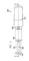
Gasless Needleless Syringe As shown in FIG. 1, the
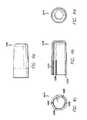
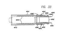
図1から図9eは、無針注射器1000を示す。無針注射器1000は、主ハウジング1002、およびオリフィス1006を有するアンプル1004を含む。アンプル1004は、接着剤、溶着、スナップ嵌めなどで主ハウジング1002と対合する開放端1008を含む。図3aから図3gで示すような代替実施形態では、アンプル1004は、主ハウジング1002の一体部品として形成される。アクチュエータキャップ1010が主ハウジング1002と対合し、密封した気体チャージ(または動力源)1012がアクチュエータキャップ1010に含まれる。穿孔カニューレ1014が主ハウジング1002に固定され、気体チャージ1012に結合されて穿孔カニューレ1014を案内するカニューレガイド1016と協働して、気体チャージ1012を密封するダイアフラム1018に穿孔する。プランジャ室1020が穿孔カニューレ1014の他方端とともに働いて、密封された気体が気体チャージ1012から放出された場合に、気体圧力の一様な分布を保証する。プランジャシャフト1022は、気体が放出されると、主ハウジング1002のボア1028内で滑動し、アンプル1004の開放端1008およびボア1030を通って、オリフィス1006を通して脱気流体を排出させる。アンプル1004に含まれ、プランジャシャフト1022の端部に適合するプランジャ1024は、プランジャシャフト1022によって動作可能であり、アンプル1004内の脱気流体を密封する。したがって、無針注射器1000は、オリフィス1006を含むオリフィス端部、およびアクチュエータキャップ1010を含むトリガ端部を有する。プランジャシャフト1022は、主ハウジングのボア1028およびアンプル1004の内部ボア1030内に滑動自在に配置される。 1 to 9e show a
アクチュエータキャップ1010がアンプル1004に向かって移動すると、気体チャージ1012もアンプル1004および穿孔カニューレ1014に向かって移動する。穿孔カニューレ1014は、穿孔カニューレ1014内に形成されて、排出気体をプランジャ室1020へと案内する導管として作用し、プランジャシャフト1022に作用する気体ボア(または流路)1040を含む。穿孔カニューレ1014は、気体チャージ1012のダイアフラム1018を穿孔する鋭利な先端1042を含む。好ましい実施形態では、気体ボア1040が鋭利な先端1042を通して開く。しかし、代替実施形態では、鋭利な先端は中実であり、気体ボア1040との連通を提供する1つまたは複数の側方口を含む。この設計は、気体チャージ1012のダイアフラム1018を形成する材料が気体ボア1040に詰まる可能性がある場合に望ましいことがある。穿孔カニューレ1014の鋭利な先端1042は、カニューレガイド1016内に形成された案内ボア1044に含まれて、カニューレ1014を気体チャージのダイアフラム1018へと誘導し、移送および作動中に穿孔カニューレ1014がシフトするのを防止する。カニューレガイド1016の他方端は、スナップ嵌め、ねじ、戻り止めおよびスロット、接着剤などによって気体チャージ1012へと取り付けるような構成である。 As
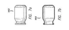
好ましい実施形態では、ダイアフラム1018は気体チャージ1012を閉鎖して密封する金属箔で裏打ちしたプラスチックの薄い積層品である。代替実施形態では、ダイアフラムは脆弱な金属盤、薄く穿孔可能な金属または箔、エラストマ材料(ゴム、プラスチックなど)、複合材、積層品、セラミック、薄いガラスなどである。好ましい実施形態では、気体チャージ1012に含まれる気体はCO2である。しかし、代替実施形態は、空気、窒素、希ガス、混合物、液体/気体の組み合わせなど、他の気体を使用してもよい。好ましい実施形態では、気体チャージ1012の容器は金属から形成する。しかし、プラスチック、ガラス、複合材、積層品、セラミック、ガラスなどの他の材料を使用してもよい。また、好ましい実施形態は、図2および図7cで示すように、凸状底部を有する。しかし、代替実施形態は、図7bで示すように平坦な底部、または無針注射器と対合し、使用前に気体チャージ1012の構造的完全性を維持するような構成である他の形状を使用してもよい。In a preferred embodiment, the
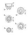
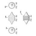
好ましい実施形態では、図5aから図5gで示すように、プランジャシャフト1022が、プランジャ1024の対応する形状を受け、据え付けるよう成形された倒立円錐形の一方端を有し、他方端は、気体チャージ1012からの気体を受けるように成形された凸状である。代替実施形態では、前面および背面は平坦でよいか、他の適切な形状を有してよい。プランジャシャフト1022は、主ハウジング1022のボア1028おおびアンプル1004のボア1030内に、その長さに沿って滑動運動するように配置される。好ましい実施形態では、プランジャシャフト1022の一方端が、主ハウジング1002のボア1028の内径とほぼ同じ外径を有し、プランジャシャフト1022の他方端は、アンプル1004のボア1030の内径とほぼ同じ外径を有して、ボア1028およびボア1030の長さに沿ったプランジャシャフト1022の自由な滑動運動を提供する。これは、プランジャシャフト1022とボア1028および1030の壁との間に、最低の摩擦で空気および流体が漏れないシールも形成する。 In a preferred embodiment, as shown in FIGS. 5a to 5g, the
プランジャ1024は、ゴムまたはプラスチックなどのエラストマ材料で形成することが好ましい。また、プランジャ1024は、作動中に捻れまたは詰まりを最小限に抑えるために、プランジャシャフト1022の端部にある一致した窪み内に填るよう成形することが好ましく、注射の終了時に残る脱気流体を最小限に抑え、注射の最初から最後までに逃げる脱気流体の速度を維持するために、オリフィス1006の形状と一致する。プランジャ1024は、アンプル1004のボア1030の内径とほぼ同じ外径を有する。プランジャ1024は、プランジャシャフト1022とオリフィス1006との間に配置される。脱気流体は、プランジャ1024の前(つまりオリフィス1006とプランジャ1024の間)に位置し、したがってプランジャ1024が前方に移動すると、脱気流体がオリフィス1006へと追いやられる。プランジャ1024の前面は、オリフィスガイド1007によって画定された開口と一致するように構成することができる。好ましい実施形態では、プランジャ1024の前面は、オリフィスガイド1007の凹状形状と一致する凸状表面を有し、その頂点はオリフィス1006である。オリフィスガイド1007の形状は、脱気流体がオリフィス1006を出るにつれ、それを収束し、加速する。オリフィスガイド1007およびプランジャ1024の一致する形状は、脱気流体の無駄を最小限に抑える傾向がある。脱気流体の大部分は、オリフィス1006を通して強制的に排出される傾向があるからである。プランジャ1024の背面の形状は、プランジャシャフト1022の前面と一致する。同様に成形した構成は、プランジャシャフト1022が前進する場合に、プランジャ1024の後部にかかる圧力を均一に分布させる。これは、プランジャ1024を前方に作動させた場合に、詰まりまたは歪みを最小限に抑える傾向がある。プランジャシャフト1022およびプランジャ1024は別個の部片として形成することが好ましい。しかし、代替実施形態では、プランジャシャフト1022およびプランジャ1024は、プランジャ1024をプランジャシャフト1022に取り付けるか、プランジャ1024に含めるようにプランジャシャフト1022を成形することによって、一体部片として形成する。
無針注射器1000を使用するには、使用者は、アンプル1004のオリフィス1006を覆うことができる保護キャップ1046を外す。使用者は、安全クリップ1026が含まれている場合は、それも外す。次に使用者は、無針注射器1000が上述したように組織に対して概ね直角になるように、オリフィス1006およびアンプル1004の端部を組織(皮膚、器官、様々な皮膚層など)に当てる。使用者は次に、アクチュエータキャップ1010を押下して、これをアンプル1004方向へ移動させる。アクチュエータキャップ1010は、所定の力の閾値に到達した後に移動し、組織が、注射器1000のさらなる前進に抗する。アクチュエータキャップ1010がアンプル1004へと移動するにつれ、気体チャージ1012およびカニューレガイド1016が穿孔カニューレ1014の鋭利な先端1042に向かって移動し、これが最終的にダイアフラム1018を穿孔して、気体チャージ1012内の気体を放出する。次に、気体は穿孔カニューレ1014内で気体ボア1040を下方向に流れて、プランジャ室1020を充填し、次にプランジャシャフト1022を押下する。放出された気体が逃げるにつれ、圧力が急速に上昇して、プランジャシャフト1022を前方へ駆動し、これはプランジャ1024をアンプル1004内のオリフィス1006に向かって前方へと駆動する。プランジャ1024が前進するにつれ、脱気流体がオリフィス1006から排出され、組織を貫通して、脱気流体を組織の表面下に送出する。 To use the
好ましい実施形態では、アンプル1004の開放端1008が外径にねじ山1054を有し、主ハウジング1002の内側には一致するねじ山1056が形成されて、アンプル1004にねじ込まれる。図面には図示されていないが、Oリングをアンプル1004と主ハウジング1002の間に配置して、追加の空気および流体が漏れないシールを提供してもよい。別個の部品を使用すると、必要に応じて、または注射する直前に無針注射器1000を組み立てられるという利点がある。また、無針注射器1000を、所望に応じて分解することができる。この組立の選択肢によって、使用者は、携帯または保存すべき完全な無針注射器1000の数を最小限に抑えながら、様々な異なる脱気流体または投与量を選択することができる。また、使用者は、腐敗しやすい脱気流体のために冷蔵庫など、様々な環境でアンプル1004を保存し、連蔵する保存スペースを最小限に抑えることができる。無針注射器1000の残りは冷蔵の必要がないからである。これは、無針注射器1000の製造も容易にする。無針注射器1000とアンプル1004とを異なる時に製造してもよいからである。あるいは、図3aから図3gで示すように、アンプル1004を主ハウジング1002の一体部品として形成する。これによって、成形部品の数および注射器器具1000の全体的費用が減少する。 In a preferred embodiment, the
(実施例2)
ラッチを含む無針注射器
図10で示すように、無針注射器は管状本体2001を備え、これは脱気流体を予め充填し、本体2001の1つまたは複数の窓2004を通して見ることができるカートリッジ2003を保持する。本体2001は、ノズル2005が突出できるようにするため、端部に口を有する。フィンガナット2006は、投与量を制御するためにオペレータによって使用され、自身上にマーク2007を有して、本体2001と同軸で配置された滑動スリーブ2002上の目盛り2008に対する自身の位置を示す。(Example 2)
Needleless Syringe Including Latch As shown in FIG. 10, the needleless syringe includes a
図11では、脱気流体2009を充填し、オリフィス2010を有するノズル2005と自由ピストン2032を装着したカートリッジ2003とが図示されている。ノズル2005は、カートリッジ2003内に密封状態で固定された図示のような別個の構成要素であるか、カートリッジ2003と一体形成してよい。カートリッジ2003は、本体2001の窓2004を通して内容が見えるように、脱気流体2009と適合する透明な材料で作成することが好ましい。カートリッジ2003は、本体2001上に形成された肩2011に突き当たり、本体2001のかしめた端部2013によってこの位置に保持される。カートリッジ2003は、肩2011とカートリッジ2003の端面との間に挿入された弾性ガスケットまたは波状ワッシャ2012によって、かしめた端部2013に向かってバイアスがかかる。 In FIG. 11, a
滑動スリーブ2002は、本体2001上に同軸で組み付けられ、本体2001上の肩2016によって支持されて肩2015に作用するばね2014によって、ノズル2005から離される。後方への運動の範囲は、1つまたは複数の止め部2017に載る肩2015によって制限される。カム2030がスリーブ内に形成され、したがってスリーブがノズル2005に向かって移動すると、カムがラッチ2026に衝突し、注入を開始する。 The sliding
支持フランジ2018が本体2001の端部に形成されて、自身と同軸の穴を有し、これに重量節約のために中空でよいねじ棒2019が通る。管状部材2020が、本体2001の後方部分内に同軸上に配置され、一方端に棒2019がねじ込まれる内ねじ2021を有する。管状部材2020の他方端は、自身内へ押しつけられる凸面2022を有するボタンを有する。あるいは、管状部材2020は、凸面2022を提供するように形成してよい。フランジ2023が管状部材上に形成されて、ばね2024を支持する働きをし、その他方端は支持フランジ2018の内面に突き当たる。図示の位置で、ばね2024は十分に圧縮し、ねじ棒2019にねじ込まれたナット2006によってこの位置に保持され、ブリッジ2025の面に当たる。図示の実施形態では、ナット2006は、相互でしっかり保持された3つの構成要素で構成される。つまり本体2006a、端部キャップ2006bおよびねじ付きインサート2006cである。インサート2006cは、棒2019にねじ込まれる構成要素であり、好ましくは金属、例えば真鍮で作成する。ナットの他の構成要素はプラスチック材料でよい。 A
ブリッジの下にあって、これによって案内されるのはラッチ2026であり、これは本体2001に取り付けられ、ねじ棒2019の1つまたは複数のねじ山と弾力的に係合する。ラッチ2026は、図15でさらに詳細に図示され、ばね材料から作成され、自身上に形成された部分ねじを有する突起2027を有し、したがって棒2019上に形成されたねじ山と十分に係合する。ラッチ2026は本体2001に取り付けられて、矢印Xの方向に弾性バイアスを有し、したがって棒2019上のねじ山との係合を維持する。矢印Xの方向に対向する運動は、ラッチをねじ山から係合解除する。以下で説明するように、棒2019は、衝撃ギャップを設定すると、矢印Yの方向に回転することなく並進し、ラッチ2026がラチェット歯止として作用する。棒2019上のねじ山は、控え壁の形態(各ねじ山が、棒の軸線に対して直角、またはほぼ直角、例えば5°である一方の面と、はるかに浅い角度、例えば45°である他方の面を有する)で、ラッチ部材として最大の強度、およびラチェット部材として軽い動作を与えることが好ましい。 Underneath the bridge and guided thereby is a
再び図11を参照すると、ナット2006をねじ棒2019へと部分的にねじ込み、したがってナット2006内に残り、棒2019の端部およびナット2006の止め面2029によって画定された自由ねじ山2028の部分がある。止めピン2031は、止め面2029に当たる頭部と、例えば接着剤などによって棒2019の内側にしっかり固定されるシャフトとを有する。止めピン2031は、ナット2006が棒2019から完全にねじで外れるのを防止する。ナット2006が反時計回りに回転すると、ピン2031の頭部が、それの配置されているナット2006の窪みの面に接触するまでしか、棒2019からねじが緩まないからである。ピン2031は、十分にねじを緩めた場合、ナット2006の自由ねじ山の最大長も画定する。 Referring again to FIG. 11, the
図12を参照すると、動作サイクルの第1段階は、ねじ棒2019上のナット2006を時計回り方向に回転することである(右手ねじであり、矢印Zの方向で見ると仮定する)。棒2019は回転を防止される。ねじのねじ山とラッチ2026との摩擦が、ナット2006と棒2019との摩擦よりはるかに大きいからである。これは、主にナットの負荷が解除され、棒2019が、ラッチ2026と係合するばねの全負荷を有するからである。したがって、棒2019は、止め面2029まではナット2006に入る。代替方法を使用して、棒2019の回転を防止することができる。例えば、ラチェットなど、または手動で動作する回り止めピンを使用する。ねじ棒は管状部材2002に、棒2019のねじ山と部材2020のねじ山2021との相互係合によって取り付けられているので、後者も後方に(つまり図11で見て右側に)移動し、ばね2024の圧縮を増加させて、管状部材2020の凸面2022とピストン2032の内面2033との間にギャップA1を生成する。棒2019をナット2006内に完全にねじ込むと、止めピン2031が、ギャップA1と等しい距離A2だけ面2034から突出する。 Referring to FIG. 12, the first stage of the operating cycle is to rotate the
図13を参照すると、ここでナット2006を、止めピン2031に接触するまで反時計回りに回転し、これはナット2006をねじ棒2019にロックする。これで、ナット2006の面2035と突き当て面2036との間にギャップがあり、そのギャップはギャップA1と等しい。次にナットを回転し続けると、ピン2031のシャフトが棒2019の側部に取り付けられているので、ねじ棒も回転し、これを後方へと緩める。したがって、ナット2006の面2035は、ブリッジ2025上の突き当て面2036からさらに離れる。ギャップの増加は、ピストンの必要なストロークと同等であり、したがって合計ギャップは、衝突ギャップA1と必要なストロークとの合計である。ナット2006は、マイクロメータの方法で、滑動スリーブ2002の目盛りに設定された周上のマークを有する。ゼロのストローク表示は、最初にねじ棒2019にロックされ、ストロークを設定するためにねじ棒を回転する直前のナット2006の位置を指す。 Referring to FIG. 13, the
無針注射器は、これで脱気流体を注入する準備が整い、図14を参照すると、無針注射器は滑動スリーブ2002によって手中に保持され、オリフィス2010が対象の表皮2038に配置される。矢印Wの方向で指止め2037に力を加える。滑動スリーブ2002は、ばね2015を圧縮して、対象に向かって移動し、したがって力は、オリフィス2010と表皮2038の間で密封を実行するように、ばね2014を通して本体2001に、したがってオリフィス2010へと伝達される。接触力が所定のレベルに到達すると、滑動スリーブ2002上のカム2030がラッチ2026に接触し、これをねじ棒2019から係合解除する。ばね2025が、管状部材2020をピストンに向かって距離A1だけ加速し、凸面2022が多大な衝撃でピストン2032の面2033に衝突する。このように、管状部材2020は、衝撃部材またはラムとして作用する。その後、ナット2006の面がブリッジ2025の面2036に合うまで、ばね2024はピストン2032を前進させ続ける。ピストンへの衝突により、脱気流体内に非常に急激な圧力上昇、事実上は衝撃波を引き起こし、これは注入オリフィスでほぼ同時に現れ、表皮を容易に貫通する。脱気流体の継続する放出は、比較的低いが、表皮の穴を開放し続けるのに十分な圧力である。 The needleless syringe is now ready to inject degassed fluid, and referring to FIG. 14, the needleless syringe is held in hand by the sliding
ばね2024は、ラムの全ストロークを通して確実な注入を保証するために、十分な予圧が与えられる。ばねが拡張する場合に、力が30%低下すると、確実な結果を生じることが判明している。あるいは、従来の螺旋コイルばねの代わりに一連の皿ばねワッシャの積み重ねがあると、ほぼ一定の力を与えることができるが、質量および費用がわずかに大きくなる。 The
このように説明した実施形態は、1つのカートリッジ分の薬剤から連続的に注射することができる安価でコンパクト、便利で使いやすい使い捨て無針注射器を提供する。動力源は、製造業者が予め装填したばねであり、カートリッジも予め充填されて、無針注射器に組み込まれる。したがって、使用者は、1つの調節ナットを回転して、注射器を表皮に押しつけるだけで、注入が自動的にトリガされる。無針注射器のサイズおよび質量は、含まれる脱気流体の量によって決定されるが、通常は、可能であれば軽量のアルミ本体および薄肉構造を使用して、5mlの無針注射器が長さ約135mm、直径(ナット)24mmで、脱気流体を含めて約85gの質量になる。 The embodiment thus described provides an inexpensive, compact, convenient and easy-to-use disposable needleless syringe that can be continuously injected from a single cartridge of medication. The power source is a spring preloaded by the manufacturer and the cartridge is also prefilled and incorporated into a needleless syringe. Thus, a user simply turns the adjustment nut and presses the syringe against the epidermis, and the injection is automatically triggered. The size and mass of a needleless syringe is determined by the amount of degassed fluid contained, but usually a 5 ml needleless syringe is about a length using a lightweight aluminum body and thin structure if possible. It is 135mm in diameter (nut) 24mm and has a mass of about 85g including degassed fluid.
(実施例3)
ラッチおよび2成分の注射可能物質を含む1回使用の無針注射器
図18aおよび図18bで示す実施形態は、1回使用の使い捨て無針注射器である。図18aを参照すると、脱気流体2009および自由ピストン2032を含むカートリッジ2003が、注射器ケース2044内にしっかり配置されて、1つまたは複数の弾性耳2045によって保持され、したがって長手方向の自由な遊びがない。ラム2046は、カートリッジと同心上に配置され、したがってピストン2032とラム2046の隣接する面の間に衝撃ギャップA1がある。ラム2046は、ばね2024によってピストン2032方向に促されるが、フランジ2018上に支持されてラム2046の心棒の切り欠き2047と係合するラッチ2026によって移動が防止される。ラッチ2026は、弾性材料から作成され、矢印Xの方向にバイアスを加えるように構成される。滑動スリーブ2002がケース2044上に配置され、カム表面2030がラッチ2026の曲げ部2053にちょうど接触し、耳2054によってケース2044上に保持される。したがって、ラッチ2026はばねとしても作用して、ケース2044に対して矢印Xの方向でスリーブ2002にバイアスを加える。脱気流体2009およびオリフィス2010は、図示のように滑動スリーブ2002にスナップ嵌めするか、カートリッジ2003に取り付けたキャップ2051によって保護される。ラム2046の遠位端2048が、滑動スリーブ2002の口2049内に配置され、注射器が装填され、使用する準備が整っていることを視覚および触覚で表示する。(Example 3)
Single-use needleless syringe containing a latch and a two-component injectable material The embodiment shown in FIGS. 18a and 18b is a single-use disposable needleless syringe. Referring to FIG. 18a, a
次に図18bを参照すると、注射するためには、キャップ2051を外し、注射器の軸が皮膚に対してほぼ直角である状態で、オリフィス2010を対象の皮膚2038上に配置する。矢印Wの方向で滑動スリーブ2002に十分な力を加えて、カム表面2030にかかるラッチ2026のバイアス力を克服する。スリーブ2002は、矢印Wの方向に移動し、したがってカム表面2030がラッチ2026をラム2046の切り欠き2047から係合解除し、これでラムはばね2024によって急速に加速されてピストン2032に衝突し、前述したように注射が遂行される。ラッチ2026がラム2046から係合解除するポイントは、対象の皮膚にかかる反応力に直接関連し、成分を適切に選択することにより、正確で反復可能な配置条件に適合することができ、注射の予測可能なトリガが保証される。滑動スリーブ2002上の安全バー2050が、(例えば落下による)ラッチ2026の偶発的な係合解除を防止し、この安全機構は、操作するまで滑動スリーブ2002の動作を防止する手動操作の回り止め(図示せず)によって補うことができる。代替構成(図示せず)では、切り欠き2047から自然に係合解除しようとするが、滑動スリーブ2002上のバーによってそれが防止されるように、ラッチ2026に上述とは反対方向にバイアスを加えてもよい。滑動スリーブ2002およびバーが動作すると、ラッチ2026が切り欠き2047から係合解除することができ、したがって注射が開始する。この例では、別個のばね手段は、滑動スリーブ2002に矢印Wの方向に対してバイアスを加える必要があることがある。 Referring now to FIG. 18b, for injection, the
図19aおよび図19bで示す実施形態は、図18aおよび図18bで示し、上述した実施形態と同様であるが、凍結乾燥した薬剤と脱気流体、または脱気流体を含む他の2部処方を保存できるように改造される。図19aは、装填し、使用する準備が整った1回分の無針注射器を示す。自由ピストン2056は中空であり、薬剤の一方の成分2060、例えば凍結乾燥薬を保存し、これはピストン2056内に砕けやすい膜2057によって保持され、これはカートリッジ2003内で保存された脱気流体2061からも薬2060を分離する。膜カッタ2058は、1つまたは複数の切刃を有し、ピストン2056内に密封および滑動自在に配置され、したがって切刃は砕けやすい膜2057から小さい距離にある。ラム2055は中空であり、そのボアには、カッタ操作棒2059が配置される。図19bも参照すると、棒2059は矢印Wの方向に押され、したがって膜カッタ2058に作用する。膜カッタ2058は膜2057を切断し、したがって脱気流体2061が薬2060と混合し、これを溶解できるようにする。無針注射器を攪拌して、混合プロセスを加速してもよい。膜の切断および混合期間を通して、保護キャップ2051がオリフィス2010を密封して、脱気流体2061の損失および/または凍結乾燥薬または他の薬剤2060との混合を防止する。薬の徹底的な溶解を保証するのに十分な時間が経過した後、キャップ2051を外し、オリフィス2010を対象の皮膚に載せ、前述したように注射を遂行する。 The embodiment shown in FIGS. 19a and 19b is similar to the embodiment shown in FIGS. 18a and 18b and described above, but with a lyophilized drug and degassed fluid, or other two-part formulation containing degassed fluid. It is modified so that it can be saved. FIG. 19a shows a single needleless syringe loaded and ready for use. The
注射の間を除き、ばね2024およびラッチ2026の主要な反応力は、支持フランジ2018にかかる。注射中、衝撃力は大きいが、これは非常に短い継続時間であり、したがって本体の構成要素は軽量構造でよい。したがって、複数の実施形態では薄い金属管の使用を述べているが、大部分の構造部品にプラスチックを使用してよい。クリープおよび歪みを引き起こすような長期の力を受けないからである。 Except during injection, the primary reactive force of
ノズルの形状は、最適な密封効率および快適性を達成するような形状であるが、ノズル内のオリフィスの幾何学的形状は、長さと直径(L:D)の比率が好ましくは2:1以下、好ましくは1:2のオーダーであり、オリフィスの出口を表皮に直接配置する。特に大きい量を配量する場合に、複数のオリフィスのノズルを使用する必要があることがあり、ノズルの各オリフィスは、理想的には2:1の最大L:D比率、好ましくは1:2を有する。 The shape of the nozzle is such as to achieve optimum sealing efficiency and comfort, but the orifice geometry within the nozzle preferably has a length to diameter (L: D) ratio of 2: 1 or less. , Preferably in the order of 1: 2, and the outlet of the orifice is placed directly on the epidermis. When dispensing particularly large quantities, it may be necessary to use multiple orifice nozzles, each orifice of the nozzle ideally having a maximum L: D ratio of 2: 1, preferably 1: 2. Have
(実施例4)
電動式無針注射器
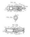
図21で示す無針注射器は、前区間3001および後区間3002を有する外部ケースを備える。区間3002は、注射器の縦軸に沿って区間3001に対して変位し、そこからばね3023によって分離される。両区間は、図21は図示されていないが第2実施形態に関して図23で示すブロックと同様の形態である抑制ブロックによって、ばねの力に抗して保持される。区間3001の前端は、密封状態で配置されたピストン3007を含むシリンダ3026を支持する。ピストン3007は中空であることが好ましいが、右手端の場合、硬質キャップによって両端が閉鎖させる。シリンダ3026は、圧縮ばねによって閉位置へとバイアスが掛けられた戻り止め弁3018、および管3017を介して、注射される脱気流体を含む容器3016に接続される。容器は、脱気流体が配量されるにつれて、空気がビンに入れるように、空気入口(図示せず)を有する。放出ノズル3020が密封状態でシリンダ3026に接続され、圧縮ばねによって閉位置へとバイアスがかかった戻り止め弁3019は、誘導ストローク中に空気がシリンダに引き込まれるのを防止する。(Example 4)
Electric Needleless Syringe The needleless syringe shown in FIG. 21 includes an outer case having a
ピストン3007は、接続棒3006の端部にある穴3027内に緩やかに配置され、したがって縦方向に自由に移動することができる。1対のピン3024がピストン3007に固定され、ピンがその対向する側でそこから半径方向に延在する。各ピンは、接続棒3006のスロット3025内で滑動する。ピストン3007の最も左側の位置で、ピン3024は個々のスロットの左手端にある。しかし、ピストン3007の最も右手の位置では、ピンは個々のスロットの右手端に到達しない。その位置は、穴3027の端部にある面3028によって画定され、ピンがそのスロットの右手端に到達する前に、ピストン3007の右手端がこれに合う。接続棒3006は、軸受け3008および3009内に滑動自在に配置されて、圧縮ばね3005によって前方へと押しやられ、圧縮ばねの一方端は、接続棒3006と一体である塊3029の面3030に作用する。このように識別される別個の塊3029が常に必要とは限らない。例えば、棒3006自体の質量で十分な場合である。ばね3005の他方端は、軸受け3009の端面に作用する。 The
モータとギアボックスのアセンブリ3004は、ケース区間3002に収容されるが、前区間3001に取り付けられて、出力シャフトが、接続棒3006に取り付けた従動子3010と係合する円筒形カム3011を担持する。モータは、以下では電気モータとして説明されているが、例えば気体で駆動するなど、他のタイプでもよい。弾性のマイクロスイッチトリップ3013を接続棒3006に装着し、したがって接続棒3006が(カム3011の回転によって)ばね3005に抗して所定の位置で後退すると、トリップ3013が前区間3001に取り付けた常時閉のマイクロスイッチ3012を動作させる。後区間3002は、電池3022およびトリガスイッチ3015を収容するハンドル部分3003を有する。電池は、トリガスイッチ3015、マイクロスイッチ3012およびモータ3004と直接で接続される。 The motor and
図22(放出した状態の無針注射器を示す)を参照すると、トリガスイッチ3015が作動し、モータ3004が励起されて、カム3011を回転し、これがばね3005に抗して接続棒3006を後退させる。後退中に、カム従動子は、図26で示したカム輪郭の傾斜部分に沿って移動する。図26の参照文字Aは、移動の途中のカム従動子の位置を指す。接続棒が後退するにつれ、ピストン3007は、接続棒3006のスロット3025の左手端がピストン3007のピン3024と接触するまで、最初は静止したままである。次に、ピストン接続棒3006とともに移動して、脱気流体を容器3016から引き出し、弁3019とピストン3007の左手端の間でシリンダ3026内に画定された計量室3031に入れる。カム従動子が最大ストローク位置に到達すると、トリップ3013がマイクロスイッチ3012を作動させて、モータ3004をオフに切り換える。カム従動子は、この時点で、ほぼゼロの揚程であるか、カムの平行部分であり、それによって「ラッチ接続」位置(図26のBで指示)に保持され、無針注射器が装填され、使用する準備が整う。 Referring to FIG. 22 (showing the needleless syringe in the released state), the
図21も参照すると、注射させるために、トリガスイッチ3015を押下し、オリフィス3021を含むノズル3020を注射すべき対象に配置して、矢印Yの方向にハンドル3003を押すことによって圧力を加える。後区間3002は、このように前区間3001に対して変位し、ノズル3021が対象に加える圧力は、ばね3023の圧縮に比例する。所定の変位量で、後区間3002に固定されたねじ3014がトリップ3013と接触し、これをマイクロスイッチ3012から離す。これによって、電池3022がモータ3004に接続され、これがカム3011を回転する。数度回転した後、カム従動子3010は突然、カム輪郭(図26の参照文字C)によって解放され、接続棒3006はその塊3029とともに、ばね3005によって急速に加速される。距離「X」(図21参照)だけ移動した後、接続棒3006の面3028が多大な衝撃力でピストン3007の端部に衝突する。この衝撃力は、ほぼ瞬時に計量室3031内の脱気流体を通して伝達され、これによって脱気流体が弁3019および対象と接触しているオリフィス3021を急速に通過する。このような脱気流体の初期衝撃は、対象の表皮を容易に貫通し、ピストン行程の残りの部分が、比較的低い圧力で脱気流体の注射を完了する。 Referring also to FIG. 21, to cause injection, pressure is applied by depressing the
極めて急速に遂行される接続棒3006の完全な注射ストロークの間、カム3011は回転し続け、カム従動子3010を取り上げ、それによってトリップ3013がマイクロスイッチ3012と接触してモータ3004をオフに切り換えるまで、接続棒3006を後退させる。こうして計量室3031が装填され、次の注射の準備が整う。 During the complete injection stroke of the connecting
ねじ3014を調節して、マイクロスイッチ3012が作動する前に、区間3001に対する区間3002の変位量を変化させる(したがってばね3023を圧縮させる)ことができる。したがって、非常に単純な調節で、対象にかかる放出オリフィス3021の圧力を制御する。対象にかかる圧力が摩擦の効果によって変動しないように、後区間3002は区間3001に対して自由に移動可能である必要がある。 The
カムが1回転すると、ばねを装填したピストンを後退させ、ラッチ接続して、解放し、カムを使用すると、非常に単純、正確かつ確実な動作特性が可能になり、オペレータが疲労することなく、高い注射速度を達成することができる。さらに、注射器の操作は、未熟練者でも容易に理解され、維持される。 With one revolution of the cam, the spring-loaded piston is retracted, latched, released, and the use of the cam allows very simple, accurate and reliable operating characteristics without operator fatigue. A high injection rate can be achieved. Furthermore, the operation of the syringe is easily understood and maintained even by an unskilled person.
(実施例5)
駆動制御機構がある無針注射器
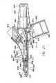
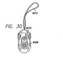
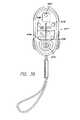
無針注射器は、図27では数字4002で全体的に指示される。最初に図27から図31を参照すると、無針注射器が、ベース部分4004、旋回可能なカートリッジアクセスドア4006、滑動可能な投与量調節ドア4008、シリンジカラー4009、皮膚センサ4010、表示盤4011、起動スイッチ4013、および携帯用ストラップ4015で構成された便利な成形プラスチックケースを含むことが分かる。図31は、これらの部品がどのように相互に適合して、一体ユニットを形成するかを示す。(Example 5)
Needleless syringe with drive control mechanism The needleless syringe is generally indicated by numeral 4002 in FIG. Referring first to FIGS. 27-31, a needleless syringe includes a
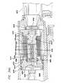
次に図34を参照すると、無針注射器4002が幾つかの基本的構成要素を含むことが分かる。最初に、交換式CO2カートリッジ4012が無針注射器の一方側に、前方に向かって配置される。カートリッジの圧力制御システムが、4014でカートリッジ4012の背後に図示されている。図34Bで最もよく図示されているように、無針注射器の他方側には、その前方にシリンジ4126が配置され、これは所定量の脱気流体を保持し、次に注射するような構成である。シリンジの後方には、シリンジの作動を制御するシリンジ制御システム4018が配置される。シリンジ制御システム4018は、カートリッジ圧力制御システム4014によって提供される圧力で制御される。表示盤4011は無針注射器の後端に配置され、無針注射器を作動させる電力ボタン4171、および無針注射器の状態をオペレータに知らせ続ける一連の表示ランプを含む。皮膚センサ4010は、無針注射器の前端に配置され、無針注射器を患者の皮膚に押しつけるにつれ、皮膚センサが適切な量だけ押下されない限り、注射プロセスの開始を防止するために使用される。最後に1対の1.5ボルトの単4電池4026を、CO2カートリッジ4012とシリンジ4126の間に配置された電池ケース4146内に装着し、無針注射器の論理回路、警告ランプなどに電力を提供する。Referring now to FIG. 34, it can be seen that the
CO2カートリッジ4012は通常、従来通りの設計の33グラムの鋼製カートリッジであり、8グラムのCO2を保持する。これは通常、約6から8回の注射に十分であるが、無針注射器を滅多に使用しない場合は、受動的な気体漏れがある結果、カートリッジ1個当たりの注射回数が減少する。CO2カートリッジ4012は、カートリッジ受け4028内で、カートリッジの丸まった前部分の曲率を補完するために湾曲した前座4030と、弾性カートリッジ密封ガスケット4034を有する後方区域との間に配置される。このガスケットは、蝶番式カートリッジアクセスドア4006を閉鎖すると、カートリッジ4012の後端を穿孔して、CO2圧力を解放するために、穿孔ピン4036がガスケットの軸方向中心にある環を通って延在するような構成になるようなサイズおよび位置にされる。The CO2 cartridge 4012 is typically a 33 gram steel cartridge of conventional design and holds 8 grams of CO2 . This is usually sufficient for about 6 to 8 injections, but if a needleless syringe is rarely used, there will be a passive gas leak resulting in a reduction in the number of injections per cartridge. The CO2 cartridge 4012 is disposed in the
図32および図33で見られるように、ドアの開閉につれてスロット4035内で滑動する1対の小さいボルト4039によって、蝶番式カートリッジアクセスドア4006を、ほぼZ字形の1対のカートリッジドア閉鎖アーム4044の端部に装着する。カートリッジアクセスドア4006を、いわゆる穿孔ブロック枠4041および穿孔ブロック4042へと、穿孔ブロックにまたがり、旋回点4043で穿孔ブロック枠に旋回自在に接続された閉鎖アーム4044によって装着する。旋回点4043は、実際はリベットの形態であり、穿孔ブロックが穿孔ブロック枠に平行に移動するのを保証するために、スロット(図示せず)が、穿孔ブロックの各側に沿って延在し、これによってリベットの内部が穿孔ブロックの移動を案内する。閉鎖アーム4044は、旋回点4048で穿孔ブロック枠4041の各側に配置された1対の旋回脚部4050にも旋回自在に装着される。脚部4050の対向する端部は、穿孔ブロックピン4046に旋回状態で接続され、これは穿孔ブロック4042を通って延在して、これに装着される。旋回可能な脚部4050はそれぞれ、図33に示すように中間部分に曲がりを含み、閉鎖アーム4044の長さに対応する。穿孔ブロックピン4046は、カートリッジアクセスドア4006を開閉し、穿孔ブロック4042を前後にシフトさせるにつれ、穿孔ブロック枠4041内の1対のフォーク端4045内で往復するように装着される。したがって、カートリッジアクセスドア4006を閉じると、脚部4050が閉鎖アーム4044の動作を穿孔ブロックピン4046に、および穿孔ブロック4042に伝達し、これは穿孔ブロック枠4041内でシフトする。これによって、前座4030が後方(図32、図33および図34の左側)への力をCO2カートリッジ4012に加える。上述したように、これによって穿孔ピン4036がカートリッジ4012の後端に穿孔する。As seen in FIGS. 32 and 33, a pair of
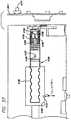
図34で最もよく図示されているように、一連の17枚のいわゆる皿ばねワッシャ4052が、前座4030と穿孔ブロック4042の間に連続して配置されて、100ポンドをわずかに超える所定の穿孔圧力を提供し、これはカートリッジアクセスドア4006が閉鎖している全時間を通して維持される。 As best illustrated in FIG. 34, a series of seventeen so-called
カートリッジ4012を破ると、加圧されたCO2ガスがカートリッジから穿孔ピン4036を通り、図34Aで最もよく図示されているように、ソレノイド弁4054へと通過し、(0.25×118”2ミクロンの)ガスフィルタ4056およびその軸方向中心を通って延在する導管4058を通る。これで、ソレノイド弁4054全体に延在するスペース4060が加圧気体で充填され、ソレノイドばね4064が配置されて軸方向にセンタリングされたばね室4062も充填される。ソレノイドばね4064は、弾性ソレノイドシール4066をソレノイド座4068に当てて、軸方向に延在する後部導管4059に圧力が流入するのを防止する。1対のOリング4070が、ソレノイド弁内に装着され、圧力制御システム4014の内壁に沿って加圧気体が流れるのを防止する。周囲リング4074がソレノイド弁4054の全周に延在して、ソレノイド弁が圧力制御システム4014内で静止したままであることを保証する。When the
概ね円筒形のピストン4076が、スペース4060とソレノイドシール4066との間に配置される。以下で説明するように、ピストン4076は、ソレノイドシール4066との組み合わせで、ソレノイド弁4054を通る気体圧力の流れを制御するよう作用する。スリーブ4061がピストンの周囲に適合し、スペース4060を十分に過ぎると、Oリング4063はCO2圧力がスリーブに沿って前方へと通るのを防止する。しかし、圧力はスリーブとピストンとの境界面に沿って後方に通過することができる。スペース4060の後方に配置されたOリング4065が、スリーブの外側にあるからである。A generally
カートリッジ圧力制御システム4014は、ポペット弁4080(図34参照)も含み、これは、後述するようにポペット弁が前方または右側にシフトすると、シャトリング現象を生成するために後部導管4059に突き当たる弾性ポペット弁シール4082を有する。ポペット弁4080は、半径方向に延在し、ポペット弁の内部をガス溜め4084と相互接続する口4086を含む。溜めがCO2の圧力を受けるポイントの前で、ポペット弁4080は図34に示す位置にある。ポペット弁ばね4088は、ポペット弁座4090がポペット弁に当たってポペット弁を閉鎖する状態で、図示の位置にポペット弁を保持する。The cartridge
カートリッジアクセスドア4006が閉鎖すると、ソレノイド弁が図示の位置にある状態で、加圧されたCO2が穿孔ピン4036およびフィルタ4056を通って流れる(図34A参照)。これは、導管4058を通ってスペース4060およびばね室4062内へと案内され、スリーブ4061とピストン4076との境界面に沿ってピストンの後方へと至る。したがって、ソレノイドシール66の表面積が含まれる場合、ピストンの前側の方が表面積が大きいので、ピストンの両端で圧力が等しくなる一方、ピストンは、ソレノイドシールがソレノイド座4068にしっかり当たっている状態で、図34および図34Aに示す位置を維持し、それによって圧力が溜め4084に入るのを防止する。When the
無針注射器を起動して、脱気流体を注入すると、ソレノイド弁4054がわずかに(約0.012インチ)前方または図34および図34Aの右側へとシフトするが、スペース4060を閉鎖するほどではない。これによって、加圧された気体が後部導管4059を通過し、ガス溜め4084に流入する。 When the needleless syringe is activated and degassed fluid is injected, the
ガス溜めから、加圧したCO2はポペット弁4080の口4086を通って流れる(図34参照)。ポペット弁内で上昇した圧力によって、ポペット弁にかかる上方向の力がポペット弁ばね4088の後方または左方向への力を上回ると、ポペット弁が持ち上がって座4090から離れ、これによって圧力が無針注射器の次の区間に突入することができる。ポペット弁は通常、480psiの圧力で座から離れて持ち上がるように設定される。ポペット弁4080がこの上昇位置にある場合、ポペット弁シール4082が後部導管4059に突き当たる。ポペット弁が開くと、ガス溜め内の圧力が降下し、したがってポペット弁ばね4088の力が再び加圧気体の力を超え、それによってポペット弁が閉鎖する。これによって、ガス溜め4084内の圧力が即座に上昇し、ポペット弁を再び持ち上げる。この現象はシャトリングと呼ばれ、脱気流体が十分に注入されるまで、短期間継続する。通常、コントローラが、ソレノイド弁の開放後0.8秒後にそれを閉鎖し、したがってシャトリングの終了時間は、コントローラによって決定される。From the gas reservoir, pressurized CO2 flows through the
最初に圧力が急激に上昇し、その後にシャトリングがあると、無針注射システムにとって理想的である圧力輪郭が生成される。図40で示すように、CO2圧力の初期急上昇は、患者の皮膚を貫通する約3920psiのシリンジ圧力を提供し、その後にシャトリング相の間、持続してほぼ一定の約1700psiの圧力が約0.5秒間続く。本明細書で使用する「ほぼ一定」という用語は、注射サイクルの0.1秒と0.56秒のポイント間で図40にて示すように約2000psiから1600psiまでの変動を含むものとする。この圧力輪郭は、即座にピークに到達するが、次に急降下する先行技術の幾つかの圧力輪郭より優れていることが判明した。1.0ccを注射すると仮定すると、約0.25ccが最高圧力で注射されるが、脱気流体の半分よりはるかに多い量が、これより圧力が低い相であるシャトリングの間に注射されることが分かる。A pressure profile that is ideal for a needleless injection system is generated when the pressure rises rapidly and then shuts down. As shown in FIG. 40, the initial spike in CO2 pressure provides a syringe pressure of about 3920 psi through the patient's skin, followed by a sustained and substantially constant pressure of about 1700 psi during the shuttling phase. Continue for 0.5 seconds. As used herein, the term “substantially constant” is intended to include a variation from about 2000 psi to 1600 psi as shown in FIG. 40 between the 0.1 second and 0.56 second points of the injection cycle. This pressure profile has been found to be superior to some of the prior art pressure profiles that quickly peak, but then plummet. Assuming 1.0 cc is injected, about 0.25 cc is injected at maximum pressure, but much more than half of the degassed fluid is injected during the shuttling phase, which is a lower pressure phase. I understand that.
ねじを切ったパペット弁圧力調節面4091のねじを内側に回して、パペット弁4080が開閉する圧力を上昇させるか、外側に回して、その圧力を低下させることができる。特殊工具(図示せず)を使用して、この調節を容易にする。 The threaded puppet valve pressure adjustment surface 4091 can be turned inward to increase the pressure at which the
図34および図34Aを参照し、パペット弁4080からCO2の圧力を受けるシリンジ制御システム4018について説明する。このシステムは、投与量補償シリンダ4094、自身に装着した圧力ピストン4098を有する投与量変動アセンブリ4096、内部シリンダ4100、後方外部シリンダ4102、および前方外部シリンダ4104を含む。いわゆるUカップシール4099および4101が、シリンジ制御システムのステージ間の圧力漏れを防止する。シリンジ制御システム4018に入るCO2の圧力により、後方外部シリンダ4102全体が、右螺旋ばね4097の圧縮作用に抗して前方または図34の右側へとシフトする。後方外部シリンダ4102は、前端が前方外部シリンダ4104の後端に接触するまでシフトし続け、これは約1/8〜3/16インチ行程に入っている。このポイントで、内部シリンダ4100はさらに約1〜1/2インチ前方へと移動し続け、合計で約1 1/8インチの行程になる。このような内部シリンダの独立した動作は、カートリッジ圧力制御システム4014内でシャトリングが開始するポイントに概ね対応する。したがって、内部シリンダ4100の独立した動作は、シャトリング作用と協働して、減少してほぼ一定であるが、より低い第2圧力相を無針注射器に提供する。この時点で、ばね4097は底に達し、その直後にコントローラによってソレノイド弁がCO2圧力を遮断する。A
投与量補償シリンダ4094が、内部シリンダ4100および後方外部シリンダ4102とともに上述した前方への動作で移動する。投与量補償シリンダ4094は、概ね円筒形の部材で、その後端に軟質ゴムバンパ(寸法が小さいので図示せず)を、その後端には図34で最もよく図示されているように、中心に配置され、軸方向に延在し、入口区画4110がある流路4108を有する。この入口区画4110は、流路4108をパペット弁4080からの流体圧力に選択的に相互接続させる。Oリング4112を投与量補償シリンダ4094に設けて、流体圧力がシリンダの外表面に沿って流れるのを防止する。シール4114を投与量補償シリンダの前端に設けて、流路4108を画定するシリンダ内壁と圧力ピストン4098との間の漏れを最小限に抑える。 The
投与量補償シリンダシステムの目的は、シリンジ内の脱気流体の量が異なると、シリンジ制御システム4018に圧力が作用する方法が多少異なる傾向があることを考慮に入れることである。圧力ピストン4098は、投与量の減少および増加につれて流路4108内をそれぞれ前方および後方に動作し、それによってピストン4098の背後にある流路4108内に画定された室のサイズを増加および減少させるので、この対応が実行される。 The purpose of the dose compensation cylinder system is to take into account that the amount of degassed fluid in the syringe tends to vary somewhat in the way pressure acts on the
螺旋ばね4115を、図34で示すように投与量補償シリンダ4094と投与量変動アセンブリ4096との間に配置する。ばね4115は、シリンジ4126およびそれに提供される脱気流体へと渡される圧力を適切な量だけ提供し、システム内に空気がないことを保証する。シリンジにこのように前方へのバイアスがかかった状態で、シリンジ内の脱気流体の量を測定することができる。以下で説明するように、投与量変動アセンブリ4096が前方または図34の右側へ行きすぎた場合、これはシリンジ内の脱気流体の量が不十分であることを示し、インタロックが無針注射器の発射を防止する。この状態は、投与量インジケータの光学中断器スペース4107に配置した投与量インジケータフラグ4106によって感知される。投与量インジケータフラグ4106は、円筒形の投与量変動補償器4120に装着され、したがってフラグの位置は概ね、シリンジ内の脱気流体の量に対応する。シリンジ内に脱気流体が十分ある場合、フラグ4106は赤外線が照明器(図示せず)から受信器(図示せず)へとスペース4107を通過するのを阻止する。シリンジ内の脱気流体の量が不十分である場合は、ばね4115によってフラグ4106が右側へとシフトし、フラグがスペース4107から引き出されて、赤外線が照明器から受信器へと通過することができ、これがコントローラへと信号を送信して、警告灯を点灯させ、無針注射器が始動相に入るのを防止する。上述した光学中断器の代わりにマイクロスイッチ、磁気スイッチ、または他の従来通りの位置センサ(図示せず)を使用することが可能である。 A
投与量変動アセンブリ4096によって、投与量を1/4ccずつ容易に調節することができる(図35参照)。これは、サムネイルマニピュレータ4118を使用して実行され、これはユニットから半径方向外側へと延在し、投与量変動補償器4120にねじ込まれて軸方向に延在する棒4113へと、ロックナット4111によって装着される。投与量変動補償器は、自身に装着された概ね半球形の突起4122を有し、これは図35で最もよく図示されている円筒形のジャケット4123に囲まれる。このジャケット4123は、周方向に延在して1つの軸方向に延在するスロット4127によって相互接続された4つのスロット4125を有し、4つのスロットは、半球形突起4122を選択的に受けるような構成である。仕切り4124を4つのスロットの間に配置して、これを画定する。図35は、仕切りが周方向の寸法で比較的狭く、したがってサムネイルマニピュレータ4118で補償器4120を40°〜45°捻るだけで、半球形突起4122が隣接する仕切りをクリアし、ばね4115からの圧力で、前方へとバイアスがかかり、軸方向に延在するスロット4127を通って次の隣接スロット4125に入り、それによって投与量を1/4cc調節することを示す。サムネイルマニピュレータ4118が解放されていない場合は、所望の投与量に応じて、突起を4つのスロットのうち別のスロット上へと選択的に案内することができる。配置されたら、サムネイルマニピュレータを解放すると、一連の回転バイアスばね4119によって投与量変動補償器4120が回転し、これによって突起が4つのスロット4125のうち1つに入る。 The
シリンジ4126は図36で最もよく図示されている。これはアンプル4128およびプランジャ4130を含む。プランジャの端部は、半径方向に延在する切り欠き4132を含み、これは投与量変動補償器4120から延在する棒4113上に適合するようなサイズにした軸方向のスロット4127と相互接続する。プランジャのフレア状端部4134は、投与量変動補償器4120の前端と突き当たるように設計される。したがって、後方外部シリンダ4102および内部シリンダ4100によって補償器に与えられる軸方向の駆動力が、プランジャを前方に駆動し、脱気流体をシリンジから強制的に排出する。シリンジは、1対の対向するフランジ4129も含み、これはその前端に隣接して配置される。シリンジのアンプル4128は、前端に小さい注射口4020を含む。口4020は通常、0.0045インチの直径であるが、望ましい皮下注射の深さに応じて0.014インチもの大きさでもよい。 The
シリンジ4126は、無針注射器の前端にあるカラー4009を通してシリンジを挿入し、押すだけで、無針注射器に填る。行程をほとんど過ぎると、ばね4115からの圧力が感じられる。波形ばね4131に当たって底に達すると、シリンジは約90°回転し、したがってフランジ4129が図34Bで示すようにシリンジのカラー4009内に係合する。シリンジがその90°を回転するにつれ、これは一緒に回転するピン4133と係合する。このピン4133が回転すると、これはシリンジロックマイクロスイッチ4140を押下し、これはシリンジが適切に設置されたという信号をコントローラに送信する。シリンジロックマイクロスイッチが押下されない場合、コントローラは警告灯を点灯し、無針注射器が始動相に入るのを防止する。 The
圧力スイッチ4148を、図31で最もよく示されるようにカートリッジ圧力制御システム4014とシリンジ制御システム4018を収容する無針注射器の部分の中間で、その側に配置する。次に図37を参照すると、圧力スイッチ4148は蛇腹4150、ばね4152、およびフラグ4156で終了する中心棒4154を含む。フラグ4156は静止光学中断器4158内に配置され、これは前述した投与量測定光学中断器とほぼ同様に、赤外線をスペース1460に通して伝達する。フラグがスペース内に配置されると、光が中断され、それ以外の場合にエミッタ(図示せず)から光を受け取る集光器(図示せず)が信号をコントローラに送信する。 A pressure switch 4148 is placed on the side of the needleless syringe portion that houses the cartridge
蛇腹4150は、CO2カートリッジ圧力を受ける。口4151が他の場合に密封され、蛇腹を囲む室4162を、ソレノイド弁4054内に存在するCO2圧力に相互接続するからである。圧力変動により、蛇腹が拡張、収縮し、これによって棒4154およびフラグ4156が光学中断器4158に対して前方および後方にわずかに動作する。ピン4155が短いスロット4157内で移動し、したがって蛇腹は、フラグ4156を変位させずに多少収縮または拡張することができる。圧力が比較的高い場合、フラグは赤外線がスペース4160を通って伝達されるのを阻止するが、圧力が想定値ほど高くない場合は、ばね4152が蛇腹4150をわずかに拡張させて、室4162に入れ、それによって棒4154がフラグ4156を光学中断器4158から引き出し、赤外線が集光器に伝播できるようにする。これは信号をコントローラに送信し、これが適切な警告灯を点灯して、始動サイクルを終了する。The
上述した蛇腹/光学中断器以外の圧力スイッチを使用することが可能である。例えば、蛇腹の代わりに螺旋またはスパイラル状のブルドン管、および上述した光学中断器以外の別のタイプのスイッチを使用することが可能である。 It is possible to use pressure switches other than the bellows / optical interrupter described above. For example, it is possible to use spiral or spiral bourdon tubes instead of bellows and other types of switches other than the optical breakers described above.
無針注射器を起動する前に、無針注射器が患者の皮膚に押しつけられていることを保証するために、皮膚センサ4010を設ける。皮膚センサは、皮膚センサばね4144の圧力で前方にバイアスがかかり、図34に示す拡張位置になった拡張棒4142を含む。軟質プラスチックジャケット4138が、図示の実施形態の拡張棒上に適合する。無針注射器を患者の皮膚に十分に押しつけると、拡張棒が皮膚センサばねの圧力に抗して押下され、ばねセンサマイクロスイッチ4144が接触し、電子信号をコントローラに送信して、起動サイクルの終了を防止する。皮膚センサが十分に押下されないと、コントローラが警告灯を点灯し、起動サイクルが終了する。皮膚センサ4010は、これによって無針注射器が皮膚に適切に配置されていない場合、無針注射器の不適切な、または他の放出を防止する機能を果たす。こうなるのは、患者がいやがる場合、または物理的な器用さの問題で、患者が無針注射器を適切に配置するのが困難である場合である。 A
図38に示す表示盤4011は、以下の赤い警告灯を含む。つまりCO2圧力警告灯4184、投与量警告灯4194、シリンジロック警告灯4191、および電池警告灯4176である。緑の「準備完了」灯4200も、電力ボタン4171同様に含まれる。The
図39の制御回路図、さらに図38に図示された無針注射器の後部に設けた表示盤4011を参照する。論理回路は符号4164で全体が指示され、表示盤のランプを点灯するために選択的に電力を提供する。回路の中心はコントローラ4166であり、これは好ましい実施形態では、Atmelプログラマブル論理デバイスであり、モデルATF 1500Lとされる。これは低電力ユニットであり、最少量の電力を使用しながら、無針注射器の動作を効果的に制御することができ、したがって電池をそれほど頻繁に交換しなくてよい。 The control circuit diagram of FIG. 39 and the
前述したように、無針注射器は幾つかのインタロックを含み、これは、幾つかの条件のいずれか1つでも満足していない場合に、ユニットの動作を防止し、オペレータに警告する。論理回路はこの機能を提供するが、これらの特徴について説明する前に、最初に回路の全体的レイアウトを参照する。 As previously mentioned, needleless syringes include several interlocks that prevent the unit from operating and alert the operator if any one of several conditions is not met. Logic circuits provide this function, but before describing these features, we first refer to the overall layout of the circuit.
4026で示す電池は、直列に装着されて3ボルトの直流電力を回路に提供する。電力スイッチ4070は、電力ボタン4171(図38参照)に対応し、直流・直流変換器4172への電力の流れを制御し、これは回路のどこかの必要に応じて3ボルトの電荷を5ボルトの電荷に変換する。電池の電力が低下している場合は、線4174を介してコントローラに信号が送信され、図38で示す表示盤4011の赤い「電池」灯4176が起動する。この光はLED4178によって電圧付加され、これはコントローラ4166のアクティブローピンに接続され、これは線4174から電池電力低下の信号があると、3ボルトの電荷をアースに送信し、それによってLEDに電圧付加して、電池交換の必要があることをオペレータに警告する。この事象は、無針注射器の起動を防止し、したがってオペレータが光を無視しても、無針注射器を起動することができない。電池に十分な電力がある場合は、コントローラに電圧が提供され、無針注射器を作動させる。 The battery shown at 4026 is mounted in series to provide 3 volts of DC power to the circuit. The
別のインタロックは、不十分なCO2圧力に対する保護を提供する。上述したように、圧力スイッチ4148はCO2圧力が十分であるか判断する。十分である場合、フラグ4156は光が光学中断器4158を通過するのを阻止し、CO2検出分岐回路4180のトランジスタが開いたままになる。この状態で、コントローラは線4181から5ボルトの電荷が入るのを感知する。CO2の圧力が不十分である場合は、フラグが引っ込んで光が光学中断器を通過することができ、これはCO2検出分岐回路4180を閉鎖し、したがって5ボルトの電荷を接地して、これがコントローラによって感知される。同時に、CO2カートリッジのLED4182が接続されているアクティブローピンがそのLED回路を接地し、そのLEDに電圧付加して、図38で示すように表示盤4011の赤いCO2カートリッジ灯4184を作動させる。この事象により、使用者が表示盤の警告灯4184を無視しても、コントローラは無針注射器の起動を防止する。Another interlock provides protection against insufficient CO2 pressure. As described above, pressure switch 4148 is CO2 pressure is determined whether sufficient. If sufficient, the
さらに別のインタロックを設けて、アンプル4128内に十分な脱気流体があることを保証する。CO2検出分岐回路4180と非常に類似した投与量検出分岐回路4190を設ける。投与量検出分岐回路4190に、線4181から5ボルトの電荷を提供し、投与量表示器の光学中断器が十分な投与量レベルを感知すると、投与量検出器分岐回路内のトランジスタが開いたままになり、コントローラが5ボルトを感知する。投与量が不十分な場合、トランジスタは閉じ、コントローラは5ボルトの電荷がないことを感知する。その場合、赤い量警告灯4194が、投与量検出器LED4192によって表示盤4011で点灯する。この光は、コントローラのアクティブローピンに接続され、これは3ボルト電荷をアースに送信し、それによってLEDを作動させる。投与量が十分でない限り、この投与量インタロックが表示盤で使用者に警告し、無針注射器の起動を防止する。Yet another interlock is provided to ensure that there is sufficient degassed fluid in
さらに別のインタロックにシリンジスイッチ4186を設け、これはユニットが起動する前にシリンジが無針注射器の所定の位置に適切にロックされていることを保証する。前述したように、この状態がシリンジロックマイクロスイッチ4140によって感知される。シリンジスイッチ4186が線4188から5ボルトの電荷を受け取る。シリンジが所定の位置に適切にロックされている場合、シリンジスイッチは閉じている。この状態で、コントローラは5ボルトの電荷を感知し、無針注射器は起動の準備が完了している。シリンジが所定の位置に適切にロックされていない場合、シリンジロックのLED4193が赤いシリンジロック警告灯4191を作動させ、コントローラは無針注射器が起動サイクルに入るのを防止する。 Yet another interlock is provided with a
これらの条件を全て(次に述べる皮膚センサを除き)満足すると、コントローラが作動して、表示盤4011の緑の「準備完了」灯4200を点滅させる。 When all of these conditions are met (except for the skin sensor described below), the controller is activated and causes the green “Ready” light 4200 on the
次に、皮膚センサのインタロックについて説明する。5ボルトの線4181から離れて皮膚センサスイッチ4196を設ける。無針注射器を起動するには、皮膚センサ4010を押下し、これによって皮膚センサスイッチ4196を閉じ、5ボルトの電荷をコントローラに送信しなければならない。この電荷をコントローラが感知しない限り、無針注射器が起動サイクルに入ることが防止される。電荷を受け取り、起動する準備が全て完了したことを示すと、皮膚センサLED4198が、表示盤4011の緑の「準備完了」灯4200を安定して作動させ、音響式インジケータ4202がビープ音を発する。 Next, the interlock of the skin sensor will be described. A
5ボルトの線4181から離れてイニシエータスイッチ4204も設け、これは表示盤のイニシエータボタン4171を押下することによって閉じる。以上の条件を全て満足すると、イニシエータスイッチが閉じて、5ボルトの電荷をコントローラに送り、これはソレノイド弁4054に電力を送って、CO2圧力が脱気流体を患者に注入するようにする。以上の条件のいずれかを満足していない場合は、適切な警告灯が点灯し、コントローラは無針注射器が起動サイクルに入るのを防止する。Apart from the 5 volt line 4181 there is also provided an initiator switch 4204 which is closed by pressing the
(実施例6)
凍結乾燥製剤を含む無針注射器
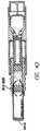
図41を参照すると、無針注射器の実施形態は、3つの区間を含み、ここでは下部区間5001、中央区間5002および上部区間5003とする。防湿性の金属箔、シール、ばね5005および圧縮したガス溜め5006などを除き、他の部品は全て、プラスチック射出成形で製造することができる。(Example 6)
Needleless Syringe Containing Lyophilized Formulation Referring to FIG. 41, a needleless syringe embodiment includes three sections, here a
下部区間は円筒形ハウジング5001を含み、これは、オリフィス5013と、キャップ5013aと、端面ピストン5009aにおいて5001の内側にある1つまたは複数、例えば3つまたは4つの等間隔の溝5012とによってさらに画定される。5001内のスペース5013bは、凍結乾燥製剤5014のためにとっておかれる。 The lower section includes a
中央区間は、外ねじ5002aを有する円筒形ハウジング5002を特徴とし、脱気流体5015aを含む流体溜め5015によってさらに画定される。流体溜め5015は、2つのピストン、例えばエラストマシールを有する剛性ピストン、またはハウジング5002の外面に金属箔シールを有するエラストマピストン5009a、5009bによって境界を区切られる。 The central section features a
ハウジング5002は、外表面の蒸着金属膜によってさらに特徴付けることができるように、ハウジング5001とは別個に製造してもよい(材料が適切な蒸気透過特徴を有していない場合、防湿層のメタライゼーションが望ましい)。ハウジング5001および5002は、組立時にしっかり対合しなければならない。この2部品のアセンブリによって、脱気流体5015aと凍結乾燥製剤5014との混合を目視検査しながら、それと同時に含まれる脱気流体5015の周囲に蒸気透過バリアを設けることができる。プランジャ5009a、5009bの外端にある金属箔シール、およびハウジング5002の外側のコーティングで構成され、メタライゼーションした防湿層は、凍結乾燥製剤の長い保存寿命を確保するのに役立つ。ガラスに加えて、金属箔およびコーティングが、水蒸気の透過に対して最善の保護を提供する。無針注射器アセンブリは箔のパウチに入れて包装できるので、流体溜めから逃げる水蒸気は箔パウチ内の空気中に蓄積する。この蓄積した水蒸気は、凍結乾燥製剤の安定性に悪影響を及ぼすことがある。これは、流体溜め5015を囲む全周の金属バリアによって防止するか、大幅に軽減することができる。 The
上部区間は、浮動プランジャ5010、スペース5011、固定したアクチュエータ5004、ばね5005、圧縮したガス溜め5006、解放ボタン5007および回り止め5016を有する円筒形のハウジング5003を含む。ハウジング5003はさらに、ハウジングの内側にあるねじ山5003aも特徴とし、これは中央区間5002の外側にあるねじ山5002aと対合する。 The upper section includes a
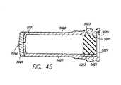
図42、図43および図44を参照して、器具の使用法を説明する。器具を箔パウチから取り出す。箔シールをハウジング5001から取り出して、ハウジング5002に組み付ける(幾つかの実施形態では、室が係合すると、箔シールが自動的に穿孔される)。オリフィス5013が上を指す状態で無針注射器を垂直姿勢にて保持し、(端部が上向きの状態で)下部区間5002を片手で把持して、他方の手でハウジング5003をハウジング5002の周囲で回転させる。この動作の結果、浮動プランジャ5010がプランジャ5009bに押し当たり、脱気流体柱5015aおよびプランジャ5009aを溝5012によって画定されたスペースに押し込む。ピストン9aおよび9bは半径方向に圧迫されている。プランジャ5009aは組み立てた状態で圧迫されているので、溝5012を囲むスペースに入ると拡張し、さらなる動作に対する抵抗を提供する。これは図42で図示されている。溝が周囲にある状態で、ピストン5009aが配置されたら、2つのピストン5009aと5009bの間の液体継ぎ手を外し、脱気流体を室5001に移送できるようにする。ハウジング5003をさらに回転すると、脱気流体5015aがピストン5009aによって溝5012を通り、凍結乾燥製剤5014を含むスペース5013bに入り、脱気流体が全てハウジング5001に押し込まれると、ハウジング5003が行程の最後に到達する(約3/4回転、回転量は、例えば選択したねじピッチに応じて変更することができる)。これは図43に図示されている。脱気流体5015aによって変位した空気は、キャップ5013aの疎水性通気口を通って逃げる。この位置で、ピストン5009aと5009bが接触し、一緒に流体移送スロット上にシールを形成する。無針注射器アセンブリは、凍結乾燥製剤が十分に溶解し、脱気流体5015aと完全に混合するまで、前後に揺動する。 The usage of the instrument will be described with reference to FIGS. 42, 43 and 44. Remove the instrument from the foil pouch. The foil seal is removed from the
凍結乾燥製剤と脱気流体の混合物を体内に注入するには、キャップ5013aを外し、無針注射器アセンブリを垂直姿勢で保持しながら、オリフィス5013を皮膚に押し当てる。次に親指を使用して、注入ボタン5007を押下する。この動作は、ボタンを回り止め5016の位置にロックし、アクチュエータ5004がスペース5011の面取りした端部に当たる。ガス溜め5006がアクチュエータ5004の尖った端部に当たると、シールが溜め5006内で破断し、それによって自身に含まれた圧縮気体を解放する。気体はアクチュエータ5004を通ってスペース5011内へと逃げ、ここで浮動プランジャ5010の底部に衝突する。プランジャ5010は対合するピストン5009a、5009bに押し当たり(図43参照)、これによってオリフィス5013を通して皮膚へと混合物を排出する。注射プロセス全体が2秒以内に完了する。ピストンの最終位置を図44に示す。この時点で、注射は終了し、無針注射器はいつでも廃棄することができる。 To inject the mixture of lyophilized formulation and degassed fluid into the body, cap 5013a is removed and
別の実施形態では、自動車のエアバッグに見られるものと同様の化学反応で、気体圧力を生成することができる。この化学反応は極めて高速かつ効率的であり、高圧窒素ガス源を生成する。さらに、2つの物質を保持する室を、別個のモジュールで提供することができる。図41の下部区間5001および中央区間5002をモジュール式構成要素と交換することができる。 In another embodiment, the gas pressure can be generated with a chemical reaction similar to that found in automobile airbags. This chemical reaction is extremely fast and efficient, producing a high pressure nitrogen gas source. Furthermore, a chamber holding the two substances can be provided in separate modules. The
以上の説明は、本発明の特定の実施形態に言及しているが、その精神から逸脱することなく、幾つかの改造ができることが当業者には容易に明白になるはずである。特に、本発明により使用するのに適切な多数の無針注射器および他の無針注射器具がある。全てではないまでも、大部分の無針注射器および他の無針注射器具を、脱気流体で充填し、それに応じて使用することができる。請求の範囲は、このような改造を本発明の真の精神および範囲に入るものとして含むよう意図される。したがって、ここで開示した実施形態は、あらゆる意味で例示的なものであり、制限的ではないと見なされ、本発明の範囲は、以上の説明ではなく、請求の範囲によって指示される。請求の範囲の同等物の意味および範囲に入る全ての変更は、これに包含されるものとする。 Although the foregoing description refers to specific embodiments of the present invention, it should be readily apparent to those skilled in the art that several modifications can be made without departing from the spirit thereof. In particular, there are numerous needleless syringes and other needleless injection devices that are suitable for use with the present invention. Most if not all needleless syringes and other needleless injection devices can be filled with degassed fluid and used accordingly. The claims are intended to cover such modifications as would fall within the true spirit and scope of the present invention. Accordingly, the embodiments disclosed herein are to be considered in all respects as illustrative and not restrictive, and the scope of the present invention is indicated by the appended claims rather than the foregoing description. All changes that come within the meaning and range of equivalency of the claims are to be embraced.
1000 無針注射器
1002 主ハウジング
1004 アンプル
1006 オリフィス
1007 オリフィスガイド
1008 開放端
1010 アクチュエータキャップ
1012 気体チャージ
1014 穿孔カニューレ
1016 カニューレガイド
1018 ダイアフラム
1020 プランジャ室
1022 プランジャシャフト
1024 プランジャ
1028 ボア
1030 ボア
1040 気体ボア
1042 鋭利な先端
1046 保護キャップ
1054 ねじ山
1056 ねじ山
1000
Claims (21)
Translated fromJapanese脱気流体を含んでいる無針注射器。A needleless syringe for performing injection of degassed fluid,
Needleless syringe containing deaerated fluid.
気体を含む気体保存室と、
前記気体を前記気体室から放出する機構を作動させる注入気体室と、をさらに備え、
前記脱気流体の前記注射が、前記気体室からの前記気体放出の直後に実施される無針注射器。The needleless syringe according to claim 1,
A gas storage chamber containing gas;
An injection gas chamber for operating a mechanism for releasing the gas from the gas chamber;
A needleless syringe in which the injection of the degassed fluid is performed immediately after the gas release from the gas chamber.
前記注射を駆動するばねをさらに備えている無針注射器。The needleless syringe according to claim 1,
A needleless syringe further comprising a spring for driving the injection.
前記注射を起動するラッチをさらに備えている無針注射器。The needleless syringe according to claim 1,
A needleless syringe further comprising a latch for initiating the injection.
該無針注射器が電動式である無針注射器。The needleless syringe according to claim 1,
A needleless syringe in which the needleless syringe is electrically operated.
前記注射を実施する前または実施中に、前記脱気流体と混合される凍結乾燥製剤をさらに備えている無針注射器。The needleless syringe according to claim 1,
A needleless syringe further comprising a lyophilized formulation that is mixed with the degassed fluid before or during the injection.
アクチュエータと、前記脱気流体を充填したカートリッジと、をさらに備え、
前記カートリッジが、流体出口と、該流体出口の内側で前記脱気流体と接触する自由ピストンと、を有し、
前記アクチュエータが、前記カートリッジと接続するような構成である前部分を有するハウジングと、カートリッジが接続されたときに前記自由ピストンに当たるよう、かつ前記自由ピストンを前記流体出口に向かって動かし続けることによって前記脱気流体の投与量がカートリッジの前記流体出口を通して排出されるよう、第1位置から前記前部分に向かって移動可能であるように前記前部分の内側で前記ハウジング内に装着された衝撃部材と、解放されたときに前記衝撃部材を前記流体出口に向かって動かすエネルギ貯蔵庫と、を備えている無針注射器。The needleless syringe according to claim 1,
An actuator, and a cartridge filled with the deaeration fluid,
The cartridge has a fluid outlet and a free piston in contact with the degassed fluid inside the fluid outlet;
The actuator having a front portion configured to connect with the cartridge; and by moving the free piston toward the fluid outlet so as to abut against the free piston when the cartridge is connected; An impact member mounted within the housing inside the front portion so as to be movable from a first position toward the front portion such that a dose of degassed fluid is discharged through the fluid outlet of a cartridge; An energy reservoir that moves the impact member toward the fluid outlet when released.
前記脱気流体を含む室と、
前記室の流体出口を含む前部分と、
該無針注射器のハンドルを含む後部分と、
前記室内の前記脱気流体と接触し、前記室の容積を減少させて含まれる前記脱気流体が前記流体出口を通して排出されるようにするために第1方向に移動可能である配量部材と、
前記配量部材と衝突してそれを前記第1方向に移動させるように配置される衝撃部材と、
該無針注射器を作動させるアクチュエータと、をさらに備えている無針注射器。The needleless syringe according to claim 1,
A chamber containing the degassed fluid;
A front portion including a fluid outlet of the chamber;
A rear portion including the handle of the needleless syringe;
A metering member in contact with the degassed fluid in the chamber and movable in a first direction to reduce the volume of the chamber and allow the contained degassed fluid to be discharged through the fluid outlet; ,
An impact member arranged to collide with the dispensing member and move it in the first direction;
And an actuator for operating the needleless syringe.
該無針注射器内に設置されて注射前に前記脱気流体を保持する無針シリンジであって、その前端に注射口を含む無針シリンジと、
薬剤を前記シリンジ口から押し出すために、前記シリンジの後端に滑動自在に装着されたシリンジプランジャと、
前記シリンジプランジャを駆動する電力を供給し、それによって前記脱気流体を前記シリンジから押し出すシリンジプランジャ駆動機構と、
前記駆動機構の動作を制御する駆動制御機構であって、複数の注射前条件のいずれか1つを満足していない場合に使用者に警告する警告システムと、複数の注射前条件のいずれか1つを満足していない場合に注射が実行されるのを防止するインタロックシステムと、前記複数の注射前条件を満足しているか感知し、信号を警告およびインタロックシステムに送って、前記注射前条件を全て満足しているかを通知する感知システムと、を含む駆動制御機構と、をさらに備えている無針注射器。The needleless syringe according to claim 1,
A needleless syringe installed in the needleless syringe and holding the degassed fluid before injection, the needleless syringe including an injection port at the front end thereof;
A syringe plunger slidably attached to the rear end of the syringe for extruding a drug from the syringe port;
A syringe plunger drive mechanism for supplying power to drive the syringe plunger, thereby pushing out the degassed fluid from the syringe;
A drive control mechanism for controlling the operation of the drive mechanism, wherein a warning system that warns a user when any one of a plurality of pre-injection conditions is not satisfied, and any one of the plurality of pre-injection conditions An interlock system that prevents an injection from being performed if not satisfied, and senses whether the plurality of pre-injection conditions are satisfied, and sends a signal to a warning and interlock system for pre-injection A needleless syringe further comprising a drive control mechanism including a sensing system that notifies whether all the conditions are satisfied.
気体源を含む気体室と該気体源に流体連通する口と変位機構とを有する第1ハウジングと、
該第1ハウジング内の可動プランジャであって、前記口および前記気体源と流体連通するプランジャと、
無針注射するよう構成されたオリフィスを画定する第2ハウジングであって、該第2ハウジング内に滑動自在に配置された第1ピストンおよび第2ピストンを含む第2ハウジングと、をさらに備え、
前記第2ハウジングと前記第1ピストンと前記第2ピストンとが、前記脱気流体を保存できる第1室を画定し、
前記第2ハウジングと前記第2ピストンとが、凍結乾燥製剤を保存して該凍結乾燥製剤と前記脱気流体との混合物を生成することができる第2室を画定し、該第2室は前記オリフィスと流体連通し、
前記プランジャは、前記第1ピストンを前記第2ピストンに向かって移動させるとともに前記第2ピストンを前記第1室と前記第2室との間に流体連通を提供する位置へと移動させるように構成されており、前記第1室は容積を減少することができ、前記第1室内の前記脱気流体は前記第2室へと移動することができ、
前記プランジャは、前記気体源から気体が放出された直後に前記第2ピストンを移動させ、前記第2室の容積を減少させ、前記混合物を前記第2室から前記オリフィスを通して排出するように構成されている無針注射器。The needleless syringe according to claim 1,
A first housing having a gas chamber containing a gas source, a port in fluid communication with the gas source, and a displacement mechanism;
A movable plunger in the first housing, wherein the plunger is in fluid communication with the port and the gas source;
A second housing defining an orifice configured for needleless injection, the first housing including a first piston and a second piston slidably disposed within the second housing;
The second housing, the first piston, and the second piston define a first chamber in which the degassed fluid can be stored;
The second housing and the second piston define a second chamber in which a lyophilized formulation can be stored to produce a mixture of the lyophilized formulation and the degassed fluid, the second chamber being Fluid communication with the orifice,
The plunger is configured to move the first piston toward the second piston and move the second piston to a position that provides fluid communication between the first chamber and the second chamber. The first chamber can be reduced in volume, and the degassed fluid in the first chamber can move to the second chamber;
The plunger is configured to move the second piston immediately after gas is released from the gas source, to reduce the volume of the second chamber, and to discharge the mixture from the second chamber through the orifice. Needleless syringe.
脱気流体を含む無針注射器で注射を実施するステップを備え、前記脱気流体が前記注射の実施前または実施中に前記無針注射器内に含まれている方法。A method of injecting degassed fluid,
Performing the injection with a needleless syringe comprising a degassed fluid, wherein the degassed fluid is contained within the needleless syringe prior to or during the performance of the injection.
前記無針注射器が、該無針注射器での注射を駆動するばねをさらに備えている方法。The method of claim 11, wherein
The method, wherein the needleless syringe further comprises a spring that drives injection with the needleless syringe.
前記無針注射器が、該無針注射器での注射を起動するラッチを備えている方法。The method of claim 11, wherein
The method wherein the needleless syringe comprises a latch that activates injection with the needleless syringe.
前記無針注射器が電動式である方法。The method of claim 11, wherein
A method in which the needleless syringe is electrically operated.
前記無針注射器に前記脱気流体を充填するステップをさらに備えている方法。The method of claim 11, wherein
Filling the needleless syringe with the degassed fluid.
前記無針注射器に前記脱気流体を充填するステップが、
無針注射器のアンプルに脱気流体を充填するステップと、
前記アンプルを前記無針注射器の残りの部分と対合させるステップと、をさらに備えている方法。The method of claim 15, wherein
Filling the needleless syringe with the degassed fluid;
Filling the ampule of a needleless syringe with degassed fluid;
Mating the ampoule with the rest of the needleless syringe.
前記無針注射器が、凍結乾燥製剤をさらに含み、該方法が、前記注射の実施前または実施中に前記脱気流体を前記凍結乾燥製剤と混合させるステップをさらに備えている方法。The method of claim 11, wherein
The method wherein the needleless syringe further comprises a lyophilized formulation, the method further comprising mixing the degassed fluid with the lyophilized formulation before or during the injection.
前記無針注射器が、アクチュエータと、前記脱気流体を充填したカートリッジと、をさらに備え、
前記カートリッジが、流体出口と、該流体出口の内側で前記脱気流体と接触する自由ピストンと、を有し、
前記アクチュエータが、前記カートリッジと接続するような構成である前部分を有するハウジングと、カートリッジが接続されたときに前記自由ピストンに当たるよう、かつ前記自由ピストンを前記流体出口に向かって動かし続けることによって前記脱気流体の投与量がカートリッジの前記流体出口を通して排出されるよう、第1位置から前記前部分に向かって移動可能であるように前記前部分の内側で前記ハウジング内に装着された衝撃部材と、解放されたときに前記衝撃部材を前記流体出口に向かって動かすエネルギ貯蔵庫と、を備えている方法。The method of claim 11, wherein
The needleless syringe further comprises an actuator and a cartridge filled with the degassed fluid;
The cartridge has a fluid outlet and a free piston in contact with the degassed fluid inside the fluid outlet;
The actuator having a front portion configured to connect with the cartridge; and by moving the free piston toward the fluid outlet so as to abut against the free piston when the cartridge is connected; An impact member mounted within the housing inside the front portion so as to be movable from a first position toward the front portion such that a dose of degassed fluid is discharged through the fluid outlet of a cartridge; An energy reservoir that moves the impact member toward the fluid outlet when released.
前記無針注射器が、
前記脱気流体を含む室と、
前記室の流体出口を含む前部分と、
前記無針注射器のハンドルを含む後部分と、
前記室内の前記脱気流体と接触し、前記室の容積を減少させて含まれる前記脱気流体が前記流体出口を通して排出されるようにするために第1方向に移動可能である配量部材と、
前記配量部材と衝突してそれを前記第1方向に移動させるように配置される衝撃部材と、
前記無針注射器を作動させるアクチュエータと、をさらに備えている方法。The method of claim 11, wherein
The needleless syringe is
A chamber containing the degassed fluid;
A front portion including a fluid outlet of the chamber;
A rear portion including a handle of the needleless syringe;
A metering member in contact with the degassed fluid in the chamber and movable in a first direction to reduce the volume of the chamber and allow the contained degassed fluid to be discharged through the fluid outlet; ,
An impact member arranged to collide with the dispensing member and move it in the first direction;
An actuator for actuating the needleless syringe.
前記無針注射器が、
該無針注射器内に設置されて注射前に前記脱気流体を保持する無針シリンジであって、その前端に注射口を含む無針シリンジと、
薬剤を前記シリンジ口から押し出すために、前記シリンジの後端に滑動自在に装着されたシリンジプランジャと、
前記シリンジプランジャを駆動する電力を供給し、それによって前記脱気流体を前記シリンジから押し出すシリンジプランジャ駆動機構と、
前記駆動機構の動作を制御する駆動制御機構であって、複数の注射前条件のいずれか1つを満足していない場合に使用者に警告する警告システムと、複数の注射前条件のいずれか1つを満足していない場合に注射が実行されるのを防止するインタロックシステムと、前記複数の注射前条件を満足しているか感知し、信号を警告およびインタロックシステムに送って、前記注射前条件を全て満足しているかを通知する感知システムと、を含む駆動機構と、をさらに備えている方法。The method of claim 11, wherein
The needleless syringe is
A needleless syringe installed in the needleless syringe and holding the degassed fluid before injection, the needleless syringe including an injection port at the front end thereof;
A syringe plunger slidably attached to the rear end of the syringe for extruding a drug from the syringe port;
A syringe plunger drive mechanism for supplying power to drive the syringe plunger, thereby pushing out the degassed fluid from the syringe;
A drive control mechanism for controlling the operation of the drive mechanism, wherein a warning system that warns a user when any one of a plurality of pre-injection conditions is not satisfied, and any one of the plurality of pre-injection conditions An interlock system that prevents an injection from being performed if not satisfied, and senses whether the plurality of pre-injection conditions are satisfied, and sends a signal to a warning and interlock system for pre-injection And a sensing system for notifying whether all the conditions are satisfied, and a driving mechanism.
前記無針注射器が、
気体源を含む気体室と該気体源に流体連通する口と変位機構とを有する第1ハウジングと、
該第1ハウジング内の可動プランジャであって、前記口および前記気体源と流体連通するプランジャと、
無針注射するよう構成されたオリフィスを画定する第2ハウジングであって、該第2ハウジング内に滑動自在に配置された第1ピストンおよび第2ピストンを含む第2ハウジングと、をさらに備え、
前記第2ハウジングと前記第1ピストンと前記第2ピストンとが、前記脱気流体を保存できる第1室を画定し、
前記第2ハウジングと前記第2ピストンとが、凍結乾燥製剤を保存して該凍結乾燥製剤と前記脱気流体との混合物を生成することができる第2室を画定し、該第2室は前記オリフィスと流体連通し、
前記プランジャは、前記第1ピストンを前記第2ピストンに向かって移動させるとともに前記第2ピストンを前記第1室と前記第2室との間に流体連通を提供する位置へと移動させるように構成されており、前記第1室は容積を減少することができ、前記第1室内の前記脱気流体は前記第2室へと移動することができ、
前記プランジャは、前記気体源から気体が放出された直後に前記第2ピストンを移動させ、前記第2室の容積を減少させ、前記混合物を前記第2室から前記オリフィスを通して排出するように構成されている方法。
The method of claim 11, wherein
The needleless syringe is
A first housing having a gas chamber containing a gas source, a port in fluid communication with the gas source, and a displacement mechanism;
A movable plunger in the first housing, wherein the plunger is in fluid communication with the port and the gas source;
A second housing defining an orifice configured for needleless injection, the first housing including a first piston and a second piston slidably disposed within the second housing;
The second housing, the first piston, and the second piston define a first chamber in which the degassed fluid can be stored;
The second housing and the second piston define a second chamber in which a lyophilized formulation can be stored to produce a mixture of the lyophilized formulation and the degassed fluid, the second chamber being Fluid communication with the orifice,
The plunger is configured to move the first piston toward the second piston and move the second piston to a position that provides fluid communication between the first chamber and the second chamber. The first chamber can be reduced in volume, the degassed fluid in the first chamber can move to the second chamber,
The plunger is configured to move the second piston immediately after gas is released from the gas source, to reduce the volume of the second chamber, and to discharge the mixture from the second chamber through the orifice. Way.
Applications Claiming Priority (2)
| Application Number | Priority Date | Filing Date | Title |
|---|---|---|---|
| US10/227,885US20040035491A1 (en) | 2002-08-26 | 2002-08-26 | Method and apparatus for needle-less injection with a degassed fluid |
| PCT/US2002/026580WO2004018023A1 (en) | 2002-08-26 | 2002-08-26 | Apparatus for needle-less injection with a degassed fluid |
Publications (1)
| Publication Number | Publication Date |
|---|---|
| JP2005536273Atrue JP2005536273A (en) | 2005-12-02 |
Family
ID=32109613
Family Applications (1)
| Application Number | Title | Priority Date | Filing Date |
|---|---|---|---|
| JP2004530740APendingJP2005536273A (en) | 2002-08-26 | 2002-08-26 | Device for needle-free injection with deaerated fluid |
Country Status (8)
| Country | Link |
|---|---|
| US (1) | US20040035491A1 (en) |
| EP (1) | EP1531889A1 (en) |
| JP (1) | JP2005536273A (en) |
| CN (1) | CN1694739A (en) |
| AU (1) | AU2002336381A1 (en) |
| CA (1) | CA2495238A1 (en) |
| MX (1) | MXPA05002072A (en) |
| WO (1) | WO2004018023A1 (en) |
Cited By (2)
| Publication number | Priority date | Publication date | Assignee | Title |
|---|---|---|---|---|
| JP2009539436A (en)* | 2006-06-07 | 2009-11-19 | アキュショット インク | Filling mechanism for needleless syringes |
| JP2012504992A (en)* | 2008-10-13 | 2012-03-01 | サノフィ−アベンティス・ドイチュラント・ゲゼルシャフト・ミット・ベシュレンクテル・ハフツング | Drug delivery device and method of manufacturing drug delivery device |
Families Citing this family (58)
| Publication number | Priority date | Publication date | Assignee | Title |
|---|---|---|---|---|
| US7448734B2 (en) | 2004-01-21 | 2008-11-11 | Silverbrook Research Pty Ltd | Inkjet printer cartridge with pagewidth printhead |
| US20050157112A1 (en) | 2004-01-21 | 2005-07-21 | Silverbrook Research Pty Ltd | Inkjet printer cradle with shaped recess for receiving a printer cartridge |
| US7328985B2 (en) | 2004-01-21 | 2008-02-12 | Silverbrook Research Pty Ltd | Inkjet printer cartridge refill dispenser with security mechanism |
| US8900187B2 (en)* | 2004-10-13 | 2014-12-02 | Mallinckrodt Llc | Powerhead control in a power injection system |
| CN103071209A (en) | 2005-11-17 | 2013-05-01 | 周吉尼克斯股份有限公司 | Delivery of viscous formulations by needle-free injection |
| FR2899836B1 (en)* | 2006-04-14 | 2010-10-15 | Olilab Llc | PROCESS FOR THE CONTINUOUS PRODUCTION BY INJECTION-COMPRESSION OF PREFORMS FOR THE MANUFACTURE OF PACKAGING AND THE INSTALLATION OF IMPLEMENTATION |
| KR100901024B1 (en)* | 2007-09-21 | 2009-06-04 | 엘지전자 주식회사 | Degassing storage of the refrigerator |
| DE102008008023A1 (en)* | 2008-02-04 | 2009-08-13 | Primojex Gmbh | System for injecting a fluid through or into the human skin |
| US8876759B2 (en)* | 2008-12-05 | 2014-11-04 | Ams Research Corporation | Devices, systems and methods for delivering fluid to tissue |
| AU2009330709B2 (en)* | 2008-12-16 | 2015-08-13 | Ams Research Corporation | Needleless injection device components, systems, and methods |
| WO2011005971A1 (en)* | 2009-07-09 | 2011-01-13 | Cook Incorporated | Spring action medical device |
| CN107029319B (en)* | 2011-11-22 | 2020-12-11 | 赛诺菲-安万特德国有限公司 | Pen-type drug injection device with controller and its actuated time-locking mechanism |
| CN204395138U (en) | 2012-04-09 | 2015-06-17 | 贝克顿·迪金森公司 | For the induction system of point medicine |
| CN108420598B (en)* | 2012-06-12 | 2021-03-09 | 爱尔康公司 | Hand-held gas mixer and injector assembly, hand-held gas injector device and method of mixing gas |
| GB201313888D0 (en) | 2013-08-02 | 2013-09-18 | Consort Medical Plc | Assembly for an autoinjector device |
| CN103405829B (en)* | 2013-08-22 | 2015-02-11 | 昆山振天智能化设备有限公司 | Novel rainproof device for needle-free injector |
| CN106470717B (en) | 2014-06-03 | 2020-09-11 | 安姆根有限公司 | Drug delivery system and method of use |
| GB201416985D0 (en)* | 2014-09-26 | 2014-11-12 | Ucb Biopharma Sprl And Bespak Europ Ltd | Housing part for an auto-injector |
| WO2016069714A1 (en) | 2014-10-28 | 2016-05-06 | Bayer Healthcare Llc | Self-orienting pressure jacket and pressure jacket-to-injector interface |
| US9199033B1 (en) | 2014-10-28 | 2015-12-01 | Bayer Healthcare Llc | Self-orienting syringe and syringe interface |
| NO2689315T3 (en) | 2014-10-28 | 2018-04-14 | ||
| JP6716566B2 (en) | 2014-12-19 | 2020-07-01 | アムジエン・インコーポレーテツド | Drug delivery device with proximity sensor |
| US11357916B2 (en) | 2014-12-19 | 2022-06-14 | Amgen Inc. | Drug delivery device with live button or user interface field |
| EP3093035A1 (en) | 2015-05-13 | 2016-11-16 | Sanofi-Aventis Deutschland GmbH | Injection device for delivery of a liquid medicament |
| WO2017083622A1 (en) | 2015-11-13 | 2017-05-18 | Bayer Healthcare Llc | Nested syringe assembly |
| WO2017115867A1 (en) | 2015-12-28 | 2017-07-06 | 株式会社ダイセル | Administering device design system, administering system, administering device design method, administering device design program, and medical device design system |
| WO2017115869A1 (en)* | 2015-12-28 | 2017-07-06 | 株式会社ダイセル | Injection device |
| CN108472452B (en)* | 2015-12-28 | 2022-05-03 | 株式会社大赛璐 | Dosing device |
| AR108963A1 (en)* | 2016-04-13 | 2018-10-17 | Merial Inc | INJECTION DEVICE WITH DRIVING MECHANISM TO MANAGE MULTIPLE LIQUID FORMULATIONS, SUCH AS VACCINES |
| US10898646B2 (en) | 2016-04-29 | 2021-01-26 | Shl Medical Ag | Container holder assembly |
| US10245382B2 (en)* | 2016-08-31 | 2019-04-02 | Liang-Chi Shen | Pneumatic needle-free injection device |
| CN109568728A (en)* | 2016-11-05 | 2019-04-05 | 王才丰 | A kind of large dosage needleless injector |
| EP3578214B1 (en)* | 2017-02-02 | 2025-06-18 | Guo-Luen Huang | Pressurized gas injection device and method |
| EP3400983B1 (en)* | 2017-05-09 | 2019-11-27 | Miltenyi Biotec B.V. & Co. KG | Refillable column system |
| US11191893B2 (en) | 2018-01-31 | 2021-12-07 | Bayer Healthcare Llc | System and method for syringe engagement with injector |
| WO2020008483A1 (en)* | 2018-07-05 | 2020-01-09 | MEDIFORM ITALIA S.r.l. | Injective administration system by using a syringe without needle that is guided by echography and related process of injection of medicines and immunostimulants by intralymphatic way |
| US11224537B2 (en) | 2018-10-19 | 2022-01-18 | Alcon Inc. | Intraocular gas injector |
| CN109432553B (en)* | 2018-11-19 | 2024-04-16 | 北京快舒尔医疗技术有限公司 | Syringe head assembly of medicine storage tube of needleless injector, medicine storage tube and needleless injector |
| CN110124157B (en)* | 2019-06-03 | 2024-02-20 | 江苏丞宇米特医疗科技有限公司 | Double pressure needleless injector |
| DE102019123730A1 (en)* | 2019-09-04 | 2021-03-04 | Henke-Sass, Wolf Gmbh | Device for applying a fluid |
| DE102019123737A1 (en)* | 2019-09-04 | 2021-03-04 | Henke-Sass, Wolf Gmbh | Device for applying a fluid |
| DE102019123734A1 (en)* | 2019-09-04 | 2021-03-04 | Henke-Sass, Wolf Gmbh | Device for applying a fluid |
| JP7681576B2 (en)* | 2019-09-05 | 2025-05-22 | ポータル インストルメンツ, インク. | Needle-free syringe with air bubble detection function |
| DE102019123870A1 (en)* | 2019-09-05 | 2021-03-11 | Pharmpur Gmbh | Pen-like syringe system |
| CN111544156A (en)* | 2019-11-14 | 2020-08-18 | 大连医科大学 | Syringe for animal experiments |
| JP7656611B2 (en)* | 2019-12-18 | 2025-04-03 | ノボ・ノルデイスク・エー/エス | Drug delivery device for delivering a predetermined fixed dose - Patents.com |
| NL2025322B1 (en)* | 2020-04-09 | 2021-10-26 | European Pharma Group B V | Refill system for medical device using jet delivery principle |
| CN111407978A (en)* | 2020-04-28 | 2020-07-14 | 温州大学 | A pulsed needleless syringe |
| US11957542B2 (en) | 2020-04-30 | 2024-04-16 | Automed Patent Holdco, Llc | Sensing complete injection for animal injection device |
| EP4370175A4 (en)* | 2021-07-12 | 2025-01-22 | Altaviz, LLC | GAS DISTRIBUTION DEVICES, SYSTEMS AND METHODS |
| IL312017A (en)* | 2021-10-11 | 2024-06-01 | Congruence Medical Solutions Llc | Automatic injection device |
| CN114099838B (en)* | 2021-11-04 | 2024-03-29 | 丰都县人民医院 | A syringe storage device with spiral pressure adjustment function |
| CN114344626B (en)* | 2022-01-24 | 2024-01-09 | 中国人民解放军空军军医大学 | Insulin syringe capable of automatically exhausting |
| CN115429978B (en)* | 2022-09-21 | 2023-06-30 | 苏州芙迈蕾医疗科技有限公司 | Intelligent electronic injector control boosting device |
| CN117504053B (en)* | 2023-11-16 | 2024-11-29 | 江苏乐聚医药科技有限公司 | Medicine tube for needle-free injection and needle-free injection including the medicine tube |
| CN119191200A (en)* | 2024-09-23 | 2024-12-27 | 东富龙科技集团股份有限公司 | Freeze-dried material transfer mechanism, double-chamber prefilled syringe production line, production method, control device and storage medium |
| CN119240064B (en)* | 2024-12-05 | 2025-04-11 | 常州市盛辉药业有限公司 | Metering and split charging equipment and method for preparing traditional Chinese medicine ointment |
| CN120404302B (en)* | 2025-07-02 | 2025-09-05 | 西安荣达石油工程有限公司 | Gas concentration diluting device for logging |
Family Cites Families (9)
| Publication number | Priority date | Publication date | Assignee | Title |
|---|---|---|---|---|
| GB9118204D0 (en) | 1991-08-23 | 1991-10-09 | Weston Terence E | Needle-less injector |
| DE69426390T2 (en) | 1993-07-31 | 2001-04-12 | Weston Medical Ltd., Stradbroke Eye | NEEDLE-FREE INJECTOR |
| GB9504878D0 (en) | 1995-03-10 | 1995-04-26 | Weston Medical Ltd | Viscously coupled actuator |
| US5730723A (en) | 1995-10-10 | 1998-03-24 | Visionary Medical Products Corporation, Inc. | Gas pressured needle-less injection device and method |
| US6080130A (en) | 1998-11-14 | 2000-06-27 | Castellano; Thomas P. | Gas power source for a needle-less injector |
| GB9525757D0 (en)* | 1995-12-16 | 1996-02-14 | Weston Medical Ltd | Needleless injector drug capsule and filling method |
| GB9607549D0 (en) | 1996-04-11 | 1996-06-12 | Weston Medical Ltd | Spring-powered dispensing device |
| DE19701494A1 (en)* | 1997-01-17 | 1998-07-23 | Boehringer Mannheim Gmbh | Transdermal injection system |
| GB0102386D0 (en)* | 2001-01-31 | 2001-03-14 | Weston Medical Ltd | Method for filling needless injector capsules |
- 2002
- 2002-08-26AUAU2002336381Apatent/AU2002336381A1/ennot_activeAbandoned
- 2002-08-26WOPCT/US2002/026580patent/WO2004018023A1/ennot_activeApplication Discontinuation
- 2002-08-26EPEP02773228Apatent/EP1531889A1/ennot_activeWithdrawn
- 2002-08-26JPJP2004530740Apatent/JP2005536273A/enactivePending
- 2002-08-26MXMXPA05002072Apatent/MXPA05002072A/enunknown
- 2002-08-26CACA002495238Apatent/CA2495238A1/ennot_activeAbandoned
- 2002-08-26CNCN02829808.XApatent/CN1694739A/enactivePending
- 2002-08-26USUS10/227,885patent/US20040035491A1/ennot_activeAbandoned
Cited By (4)
| Publication number | Priority date | Publication date | Assignee | Title |
|---|---|---|---|---|
| JP2009539436A (en)* | 2006-06-07 | 2009-11-19 | アキュショット インク | Filling mechanism for needleless syringes |
| KR101386532B1 (en)* | 2006-06-07 | 2014-04-17 | 아큐샷 인크. | Charging mechanism for a needle-free injector |
| JP2012504992A (en)* | 2008-10-13 | 2012-03-01 | サノフィ−アベンティス・ドイチュラント・ゲゼルシャフト・ミット・ベシュレンクテル・ハフツング | Drug delivery device and method of manufacturing drug delivery device |
| KR101677065B1 (en) | 2008-10-13 | 2016-11-29 | 사노피-아벤티스 도이칠란트 게엠베하 | Drug delivery device and method of manufacturing a drug delivery device |
Also Published As
| Publication number | Publication date |
|---|---|
| WO2004018023A1 (en) | 2004-03-04 |
| CN1694739A (en) | 2005-11-09 |
| EP1531889A1 (en) | 2005-05-25 |
| CA2495238A1 (en) | 2004-03-04 |
| AU2002336381A1 (en) | 2004-03-11 |
| US20040035491A1 (en) | 2004-02-26 |
| MXPA05002072A (en) | 2005-06-08 |
Similar Documents
| Publication | Publication Date | Title |
|---|---|---|
| JP2005536273A (en) | Device for needle-free injection with deaerated fluid | |
| US20050192530A1 (en) | Method and apparatus for needle-less injection with a degassed fluid | |
| US8684968B2 (en) | Hypodermic drug delivery reservoir and apparatus | |
| US6673034B2 (en) | Gas power sources for a needle-less injector and needle-less injectors incorporating the same | |
| JP3487856B2 (en) | Needleless syringe | |
| JP4771508B2 (en) | Auto-injector powered by pneumatic pressure | |
| US8100853B2 (en) | Methodology for drug delivery device with sliding valve | |
| JP2728141B2 (en) | Disposable needle-free injection device | |
| KR101704106B1 (en) | Needleless injection device | |
| CN100546665C (en) | Shock chamber for spray supply | |
| JP2016524513A (en) | Vial transfer and injection instruments and methods | |
| CN104520198A (en) | Improved syringe | |
| CN102802699A (en) | Medicament Delivery Device | |
| JP2002524213A (en) | Needleless syringe cartridge | |
| JP2008536588A (en) | Administration device for administering a fluid formulation | |
| US20240216611A1 (en) | On-body medicament delivery devices for administration of medicament | |
| WO2003051435A1 (en) | Pneumatically retractable safety syringe | |
| HU220228B (en) | Medical device for delivering a therapeutic agent against the skin of patient | |
| HK1025920A (en) | Needle-less injector | |
| MXPA01002620A (en) | Needleless injector cartridge | |
| HK1010697B (en) | Needle-less injector |
Legal Events
| Date | Code | Title | Description |
|---|---|---|---|
| A131 | Notification of reasons for refusal | Free format text:JAPANESE INTERMEDIATE CODE: A131 Effective date:20081014 | |
| A977 | Report on retrieval | Free format text:JAPANESE INTERMEDIATE CODE: A971007 Effective date:20081016 |