JP2005536145A - Method and apparatus for providing power line carrier communications in customer premises - Google Patents
Method and apparatus for providing power line carrier communications in customer premisesDownload PDFInfo
- Publication number
- JP2005536145A JP2005536145AJP2004529053AJP2004529053AJP2005536145AJP 2005536145 AJP2005536145 AJP 2005536145AJP 2004529053 AJP2004529053 AJP 2004529053AJP 2004529053 AJP2004529053 AJP 2004529053AJP 2005536145 AJP2005536145 AJP 2005536145A
- Authority
- JP
- Japan
- Prior art keywords
- power line
- line carrier
- carrier signal
- power
- distribution network
- Prior art date
- Legal status (The legal status is an assumption and is not a legal conclusion. Google has not performed a legal analysis and makes no representation as to the accuracy of the status listed.)
- Pending
Links
- 238000004891communicationMethods0.000titleclaimsabstractdescription14
- 238000000034methodMethods0.000titleclaimsabstractdescription14
- 230000008878couplingEffects0.000claimsdescription14
- 238000010168coupling processMethods0.000claimsdescription14
- 238000005859coupling reactionMethods0.000claimsdescription14
- 238000009429electrical wiringMethods0.000claimsdescription2
- 238000005516engineering processMethods0.000description7
- 230000008901benefitEffects0.000description4
- 239000003990capacitorSubstances0.000description3
- 238000009434installationMethods0.000description3
- 230000005540biological transmissionEffects0.000description2
- 238000010586diagramMethods0.000description2
- 230000000694effectsEffects0.000description2
- 238000002955isolationMethods0.000description2
- 230000001052transient effectEffects0.000description2
- 230000004888barrier functionEffects0.000description1
- 230000005284excitationEffects0.000description1
- 230000006872improvementEffects0.000description1
- 238000012423maintenanceMethods0.000description1
- 239000000463materialSubstances0.000description1
- 229910044991metal oxideInorganic materials0.000description1
- 150000004706metal oxidesChemical class0.000description1
- 230000007935neutral effectEffects0.000description1
- 230000008569processEffects0.000description1
- 238000009418renovationMethods0.000description1
- 230000001629suppressionEffects0.000description1
Images

Classifications
- H—ELECTRICITY
- H04—ELECTRIC COMMUNICATION TECHNIQUE
- H04B—TRANSMISSION
- H04B3/00—Line transmission systems
- H04B3/54—Systems for transmission via power distribution lines
- H04B3/56—Circuits for coupling, blocking, or by-passing of signals
- H—ELECTRICITY
- H04—ELECTRIC COMMUNICATION TECHNIQUE
- H04B—TRANSMISSION
- H04B3/00—Line transmission systems
- H04B3/54—Systems for transmission via power distribution lines
- H04B3/542—Systems for transmission via power distribution lines the information being in digital form
- H—ELECTRICITY
- H04—ELECTRIC COMMUNICATION TECHNIQUE
- H04B—TRANSMISSION
- H04B2203/00—Indexing scheme relating to line transmission systems
- H04B2203/54—Aspects of powerline communications not already covered by H04B3/54 and its subgroups
- H04B2203/5429—Applications for powerline communications
- H04B2203/5433—Remote metering
- H—ELECTRICITY
- H04—ELECTRIC COMMUNICATION TECHNIQUE
- H04B—TRANSMISSION
- H04B2203/00—Indexing scheme relating to line transmission systems
- H04B2203/54—Aspects of powerline communications not already covered by H04B3/54 and its subgroups
- H04B2203/5429—Applications for powerline communications
- H04B2203/5445—Local network
- H—ELECTRICITY
- H04—ELECTRIC COMMUNICATION TECHNIQUE
- H04B—TRANSMISSION
- H04B2203/00—Indexing scheme relating to line transmission systems
- H04B2203/54—Aspects of powerline communications not already covered by H04B3/54 and its subgroups
- H04B2203/5462—Systems for power line communications
- H04B2203/5466—Systems for power line communications using three phases conductors
- H—ELECTRICITY
- H04—ELECTRIC COMMUNICATION TECHNIQUE
- H04B—TRANSMISSION
- H04B2203/00—Indexing scheme relating to line transmission systems
- H04B2203/54—Aspects of powerline communications not already covered by H04B3/54 and its subgroups
- H04B2203/5462—Systems for power line communications
- H04B2203/5483—Systems for power line communications using coupling circuits
Landscapes
- Engineering & Computer Science (AREA)
- Power Engineering (AREA)
- Computer Networks & Wireless Communication (AREA)
- Signal Processing (AREA)
- Cable Transmission Systems, Equalization Of Radio And Reduction Of Echo (AREA)
- Remote Monitoring And Control Of Power-Distribution Networks (AREA)
Abstract
Translated fromJapaneseDescription
Translated fromJapanese本出願は、2002年8月16日付けの米国特許出願No.10/219,811に基づく優先権主張を伴っており、本出願においてこの文献を参考文献として組み入れる。 This application is a U.S. patent application no. With priority claim under 10 / 219,811, which is incorporated herein by reference.
コンピュータ及びその他の電子情報機器の相互接続を可能とすることは、今日、人々が生活し、仕事をするに際しての共通の要請である。ローカルエリアネットワーク(LAN)を構築するのに必要とされる電気的な接続は、通常、専用のデータ電送配線を各建物内及びこれらの建物の間に設けることによって達成される。ワイヤレスな方法(すなわち、無線による方法)がまた、この要請を満たすために発展せしめられてきた。 Enabling the interconnection of computers and other electronic information devices is a common requirement when people live and work today. The electrical connections required to build a local area network (LAN) are typically achieved by providing dedicated data transmission wiring within each building and between these buildings. Wireless methods (ie, wireless methods) have also been developed to meet this need.
最近では、電力線網のインフラを使って、同時にデータを高速で伝送するための技術が実現されている。この電力線搬送通信(PLC)の技術は、典型的には、電力線上において発生せしめられた50MHz以下の周波数の変調無線周波数(RF)の信号を使ってデータを伝送する。 Recently, a technology for simultaneously transmitting data at high speed using an infrastructure of a power line network has been realized. In this power line carrier communication (PLC) technology, data is typically transmitted using a modulated radio frequency (RF) signal having a frequency of 50 MHz or less generated on the power line.
PLCの技術によって、幾つかの重要な実用的な利益がもたされている。すなわち、特に現存する建物中において、電気的な配線が必要に応じてなされ、して、データが直接的にほんのわずか付加的なコストをかけるだけで導入され得る。同様に、電気コンセントは現代の建物中においてはどこにでも存在しており、データが同時にすべてのコンセントにおて利用可能となるような場合には、重要な操作上の便利性が実現される。 The PLC technology provides several important practical benefits. That is, especially in existing buildings, electrical wiring can be made as needed, and data can be introduced directly with very little additional cost. Similarly, electrical outlets are ubiquitous in modern buildings, providing significant operational convenience when data is available to all outlets simultaneously.
PLC技術の別の利点は、それによって達成される効果が、無線による方法の場合と比べて著しく、特に、ほとんど無線信号を透過させない重厚な材料から作られた商業用ビルディングの場合、両者の効果の差異は著しい。PLC技術が無線による方法より勝っている別の利点は、本質的に、よりセキュアな環境がもたらされるというとである。というのは、この方式によれば、ネットワークを形成するために物理的な接続が必要とされるからである。 Another advantage of PLC technology is that the effect achieved thereby is significant compared to the wireless method, especially in commercial buildings made of heavy materials that hardly transmit radio signals. The difference is remarkable. Another advantage of PLC technology over wireless methods is that it inherently provides a more secure environment. This is because according to this method, a physical connection is required to form a network.
本発明は、PLC技術をローカルエリアネットワークに導入し、そして、使用の際に生じる幾つかの重要な問題に取り組もうとしたものである。 The present invention introduces PLC technology into a local area network and attempts to address some important issues that arise in use.
最新のRANは、“ハブ及びスポーク”トポロジーに基づいて構築されており、中心となるサーバ装置が多数のユーザを支援し、また、ワイドエリアネットワーク(WAN)及び/又はインターネットへのゲートウェイを提供する。PLCネットワークに対する最大の効用は、その物理的な構成がRANの論理的トポロジーを反映するとき、すなわち、PLCゲートウェイがスペース内の電気的な中心に配置されるときに得られ、この場合、すべてのコンセントが最適状態で使用可能なPLC信号の供給を受ける。この電気的な中心となるポイントは、しばしば、サービスクロゼット又はサービス基盤内のほとんど人の手が入らない電気的なパネルから構成され、それ以外のデータ処理装置と決して同じ場所に配置されていない。本発明は、この最適なポイントにおいてPLC信号を遠隔的に入力するための簡単な手段を提供するものである。 Modern RANs are built on a “hub and spoke” topology, with the central server device supporting a large number of users and providing a gateway to a wide area network (WAN) and / or the Internet. . Maximum utility for a PLC network is obtained when its physical configuration reflects the logical topology of the RAN, i.e. when the PLC gateway is placed in the electrical center in the space, in which case all The outlet receives a PLC signal that can be used in an optimum state. This electrical central point often consists of a service closet or electrical panel in the service infrastructure that is barely accessible, and is never co-located with other data processing devices. The present invention provides a simple means for remotely inputting a PLC signal at this optimal point.
本発明の別の重要な課題、特に、商業用ビルディングでの実施に際しての課題は、3相電力配線が共通に使用され、建物内のPLCネットワークの適当な信号到達範囲が、3つの位相すべてがPLC信号によって励起されたときにのみ達成されるようにすることにある。本発明は、電力線の3つの位相のすべての同時的な励起のための単一のPLC信号を与える。 Another important issue of the present invention, particularly when implemented in a commercial building, is that three-phase power wiring is commonly used and the appropriate signal reach of the PLC network in the building is such that all three phases are It is to be achieved only when excited by the PLC signal. The present invention provides a single PLC signal for simultaneous excitation of all three phases of the power line.
本発明のさらに別の課題は、信号に対する自然なバリア(又はそれらを完全に遮蔽するもの)を備えた環境中にPLCネットワークを設置する場合に生じる。一般的な状況として、建物が改築され、そして、建物のすべての区画がもはや共通の電力源を必要としなくなった場合が想定される。別の一般的な状況としては、しばしば、分配効率および電気的な隔離性を向上させるために、電力が中心となるポイントから供給され、その後、トランスを経てスペース内のすべての区画に分配されるような場合が想定される。本発明はまた、単一のPLC信号を、適当な信号到達範囲を得るのに必要とされる任意の個数の離れたポイントに入力するための簡単かつフレキシブルな手段を提供する。 Yet another problem of the present invention arises when installing a PLC network in an environment with natural barriers to signals (or those that completely shield them). A common situation is when a building has been renovated and all sections of the building no longer require a common power source. Another common situation is that power is often supplied from a central point to improve distribution efficiency and electrical isolation, and then distributed through the transformer to all compartments in the space Such a case is assumed. The present invention also provides a simple and flexible means for entering a single PLC signal at any number of distant points required to obtain the proper signal reach.
本発明によるシステムは、電力線搬送信号を、離れた位置に配置されたカプリング装置に対して供給することによって、通信信号を建物の3相電力網に結合させる。この場合、カプリング装置は、3つの位相のそれぞれが、離れた信号源からPLC信号の供給を受け得るように構成される。本発明の別の特徴によれば、信号は建物のそれぞれの区画に対して独立なカプリング装置を与えることによって、PLC信号に関して異なる電気的な隔離性を備えた建物の2つ又はそれ以上の異なる区画に供給され得る。 The system according to the present invention couples communication signals to the building's three-phase power network by providing power line carrier signals to remotely located coupling devices. In this case, the coupling device is configured such that each of the three phases can be supplied with a PLC signal from a remote signal source. According to another feature of the invention, the signal is provided with an independent coupling device for each section of the building, thereby providing two or more different of the buildings with different electrical isolation with respect to the PLC signal. Can be supplied to the compartment.
本発明のさらに別の技術的課題及び新規な構成及び長所が、以下に続く発明の詳細な説明から明らかとなるであろう。 Further technical problems and novel configurations and advantages of the present invention will become apparent from the detailed description of the invention that follows.
本発明の実施例は、PLC技術によってもたらされるデータの伝送を改善することを目的としたものである。ここに説明される搬送電流カプラは、建物の電力供給配線への物理的接続を可能とするための手段を提供する一方、その改良点の多くのPLC信号を入力する適当なポイントを識別するということから生じている。 Embodiments of the present invention are aimed at improving the transmission of data provided by PLC technology. The carrier current coupler described herein provides a means for allowing physical connection to the building's power supply wiring, while identifying the appropriate point to input many PLC signals of its improvement. It stems from that.
1つの共通の課題は、中央に配置された単一の装置(しばしば“ゲートウェイ”と呼ばれる)からのPLC信号を建物の電力配線に導入することによって建物のすべてのコンセントがそれにプラグで接続された第2の装置(しばしば、“ターミナル”と呼ばれる)に対する適当な信号を受信し、適当に機能するようにさせることにある。PLC信号の任意の配線に沿った減衰は、予測するのが難しく、著しく変動する。したがって、すべてのコンセントに等しい信号レベルを供給することは一般に不可能である。より達成可能な目的は、建物及びそのすべてのコンセントを一緒にして正常に動作するシステムとすること、すなわち、個々のコンセントはいずれもPLC信号から完全に遮断され、そして、信号の振幅が、信号入力ポイントからの距離につれて、合理的に予測し得る挙動で減衰するようにすることである。 One common challenge is that all building outlets are plugged into it by introducing PLC signals from a single centrally located device (often called a “gateway”) into the building's power wiring. It is to receive the appropriate signal for the second device (often called the “terminal”) and make it function properly. The attenuation along any wiring of the PLC signal is difficult to predict and varies significantly. Therefore, it is generally impossible to provide equal signal levels to all outlets. A more achievable objective is to make the building and all its outlets work together normally, ie all individual outlets are completely cut off from the PLC signal and the signal amplitude is Attenuating with a reasonably predictable behavior with distance from the input point.
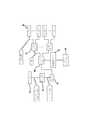
図1は、建物の配電システムの簡略化されたブロック図であり、上述の議論を説明するために用いられる。電力幹線からの電力は、ターミナルボックス32を介して降圧トランス31を経て設備内に導入される。そして、メータ33によって使用量の検針のために測定される。電力は、その後、サービスパネル30に送られ、そこで分割された後、パネルボード34を介して多数のコンセント35に向けられる。しかしながら、上で数えられたポイントのすべてにおいて、ゲートウェイPLC信号を導入することは、確実に実行可能であり、最適のポイントはおそらくサービスパネル30となる。なぜなら、サービスパネル30はすべてのコンセント35に対して対称的に電力を供給し得るからである。(もし、そこに入力されたならば、)トランス31からサービスパネル30に向かって配線に沿って減衰するPLC信号は完全に浪費される。なぜなら、そこには如何なるターミナル装置も接続されていないからである。同様に、ゲートウェイ信号をコンセント35の1つに入力することは実現可能であるが、最適なものではない。なぜなら、コンセント35は、おそらくその他のすべてのコンセントに関して対称的に分布していないからである。 FIG. 1 is a simplified block diagram of a building power distribution system and is used to illustrate the above discussion. Electric power from the main power line is introduced into the facility via the
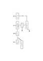
受動カプラの使用を最大限に実現する最適化されたシステムは、搬送電流カプラ20をサービスパネル30に接続し、ゲートウェイ40からのPLC信号をそのポイントにおいて建物内に入力し、そして、任意の共通の利用可能な手段を用いて多数のコンセントにおいてデータスループット性能を測定することである。図2はその接続を行うための詳細な構成を示している。 An optimized system that maximizes the use of passive couplers connects the carrier
図2を参照して、サービスパネル30は上で議論されたものと同じ構成を有している。米国電気規定において規定された許容される電気的な安全性の要件は、カットオフスイッチ22及びヒューズ/回路遮断器21が備えられているというとを要求する。微小なPLC信号電流のみが、この経路に沿って生じると予想されるにもかかわらず、カットオフスイッチ22は、設置/メンテナンスの間に電力線電圧からサービス作業員を保護するために必要とされ、ヒューズ/回路遮断器は、搬送電流カプラ20の破滅的な故障が生じた場合に建物全体を保護するために必要とされる。ターミナルブロック23は配線のための便利なアタッチメントポイントを提供する。 Referring to FIG. 2, the
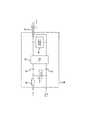
考慮されるべき付加的な次元は、商業用ビルディングにおける3相電力の共通の使用である。この場合、サービスパネル30は3本のホットワイヤ(しばしば、“L1”、“L2”及び“L3”と呼ばれる)と中性ワイヤと設置ワイヤを有している。当初の建物内配線計画の目的は、3つの位相のすべてを横切る負荷をバランスさせ、それによってほぼ1/3のコンセント35の下流がL1、L2及びL3のそれぞれに最終的に接続されるようにすることである。それ故、PLC信号をすべてのコンセントに対して与えるために信号は分割されて、3つの位相のすべてに対して同時に供給されなければならない。図3はこの接続を説明したものである。 An additional dimension to be considered is the common use of three-phase power in commercial buildings. In this case, the
図3は搬送電流カプラ20の内部の詳細な構成を示したものである。ケートウェイからのシングルエンドのPLC信号は、同軸ケーブル17を通じて導入され、その後、バラントランス14及びコンデンサ12を経て各電流位相に結合される。コンデンサ13は゛選択的なものであり、必要な場合に使用される。金属酸化物抵抗器(MOV)11がゲートウェイ40のパーツに損害を与えるおそれのある過渡電力を抑制するために使用される。ゲートウェイのパーツに対する付加的な保護が、過渡電圧抑制回路16によってもたらされる。第2のヒューズ15(一般に、非常に低いアンベア数で機能する)が、MOV11のショートによって故障に対する保護を行うために使用される。コンデンサ12、ヒューズ15及びMOV11を含む回路は、簡単に複製され、3つの位相のすべてに対して電力を供給する。 FIG. 3 shows a detailed configuration inside the carrier
もし、設置が上述のように完了し、許容し得るデータスループットの結果が得られたなら、さらに作業をする必要はなくなる。他方、(再び、図1を参照して)次のことがわかる。すなわち、幾つかのコンセント35は適当なPLC信号を有していない。この例の目的のために、1つの特定のパネルボード34から電力供給を受ける多くのコンセント35が適切なデータスループット性能をもたらさせないと仮定しよう。観察手段及び/又は分析手段を用いることによって、これがなぜ生じるのかを究明し、その状況を改善するとができる。しかしながら、壁の裏側に備えられた現存する配線の詳細及び/又はその建物の過去の改築の履歴は、容易に明らかにはならない。図4(“マルチポイントPLC信号入力”)は、本発明によって与えられた別の実施例によるこの問題の解決法を示している。 If the installation is completed as described above and an acceptable data throughput result is obtained, no further work is required. On the other hand (again, referring again to FIG. 1) we can see that That is, some
図4は、信号到達範囲の問題を改善するためにサービスパネル30に加えて、あるポイントにおいて同時に入力された信号を示したものである。同軸スプリッタ50は、ブロードバンド信号を2つ又はそれ以上の位置において使用するための分割するためにケーブルテレビシステムにおいて使用される共通に利用可能な安価な装置である。これらの装置は、同様に、PLC信号を分割するためにも使用され得る。この実施例において、同軸ケーブル17に沿ったゲートウェイ40のPLC信号出力は分割され、そして、個々の同軸ケーブル18及び19を経て2つの搬送電流カプラ20に向けられる。搬送電流カプラの一方は、すでに述べたようにサービスパネル30に備えられ、他方は、不適当な性能を備えたコンセント35を有する特定のパネルボード34に備えられる。それによって、当初のPLC信号がこの特定のパネルボードに到達することを妨げるという物理的な問題が回避される。さらに、PLC信号電力は依然として建物内にとどまっているので、唯一生ずる損失は、同軸スプリッタ50内において生ずる微々たる減衰のみである。このプロセスの効果はそれ故、適切な信号到達範囲をもたらし、そしてそこで、それが消失する前にスペースの残りの領域内において信号振幅をわずかに減衰させるということにある。この技術の多くの変形例は、後にそれらが発見されたときに特定のPLC信号到達範囲の問題に取り組むために利用され得る。 FIG. 4 shows signals simultaneously input at a certain point in addition to the
以上に説明した開示は、単に発明を説明するためのものであって、発明の構成を限定することを意図するものではない。本発明の構成の範囲内においてこれらの開示された実施例の変形例を当業者は容易に案出することができる。本発明は、添付の請求の範囲に記載された構成の範囲内にあるすべてのものを含んでいることはいうまでもない。 The disclosure described above is merely for explaining the invention and is not intended to limit the configuration of the invention. Those skilled in the art can easily devise variations of these disclosed embodiments within the scope of the present invention. It goes without saying that the present invention includes everything that falls within the scope of the constitution described in the appended claims.
Claims (17)
Translated fromJapanese電力線搬送信号を与える搬送電流装置と、
少なくとも1つの前記サービスパネルに接続され、前記電力線搬送信号を前記建物の3相配電網のそれぞれの位相に結合するための受動カプリング装置と、を有していることを特徴とするシステム。In a system for coupling communication signals to a three-phase power line network of a building with at least one service panel,
A carrier current device for providing a power line carrier signal;
And a passive coupling device connected to at least one of the service panels for coupling the power line carrier signal to a respective phase of the three-phase distribution network of the building.
第1の位置に配置されて電力搬送信号を出力するデータ通信源と、
前記配電網における前記第1の位置から離れたサービス位置に直接接続されて前記電力線搬送信号を受信し、前記データを前記電力線網上に分布させる受動カプラと、を有していることを特徴とするシステム。In a system for changing the distribution network so that data communication can be performed,
A data communication source disposed at a first position and outputting a power carrier signal;
A passive coupler that is directly connected to a service location remote from the first location in the power distribution network, receives the power line carrier signal, and distributes the data on the power line network. System.
電力線搬送信号を出力するデータ通信信号源と、
第1の受動カプラ及び少なくとも1つの第2の受動カプラとを有しており、
前記受動カプラは、それぞれ、前記第1の配電網部分及び前記少なくとも1つの第2の配電網部分のそれぞれのサービス位置に直接接続され、前記第1及び第2の配電網部分はそれぞれ、データ通信に関して互いに電気的に分離され、前記第1及び少なくとも1つの第2の受動カプラはそれぞれ、前記データ通信信号源から出力された電力線搬送信号を与えるようになっていることを特徴とするシステム。In a system for providing a communication signal to a first distribution network portion for providing data communication to the distribution network and to at least one second distribution network portion,
A data communication signal source for outputting a power line carrier signal;
A first passive coupler and at least one second passive coupler;
Each of the passive couplers is directly connected to a respective service location of the first distribution network portion and the at least one second distribution network portion, and the first and second distribution network portions are each configured for data communication. And wherein each of the first and at least one second passive coupler provides a power line carrier signal output from the data communication signal source.
第1の位置において電力線搬送信号を生成するステップと、
前記電力線搬送信号を、前記配電システムにおける前記第1の位置から離れたサービス位置に受動的に結合するステップと、を有していることを特徴とする方法。In a method for introducing communication data into a building distribution system,
Generating a power line carrier signal at a first position;
Passively coupling the power line carrier signal to a service location remote from the first location in the power distribution system.
Applications Claiming Priority (2)
| Application Number | Priority Date | Filing Date | Title |
|---|---|---|---|
| US10/219,811US6975212B2 (en) | 2001-10-02 | 2002-08-16 | Method and apparatus for attaching power line communications to customer premises |
| PCT/US2003/009557WO2004017621A1 (en) | 2002-08-16 | 2003-03-28 | Method and apparatus for attaching power line communications to customer premises |
Publications (1)
| Publication Number | Publication Date |
|---|---|
| JP2005536145Atrue JP2005536145A (en) | 2005-11-24 |
Family
ID=31886601
Family Applications (1)
| Application Number | Title | Priority Date | Filing Date |
|---|---|---|---|
| JP2004529053APendingJP2005536145A (en) | 2002-08-16 | 2003-03-28 | Method and apparatus for providing power line carrier communications in customer premises |
Country Status (7)
| Country | Link |
|---|---|
| US (3) | US6975212B2 (en) |
| EP (1) | EP1532803A4 (en) |
| JP (1) | JP2005536145A (en) |
| CN (1) | CN1675916A (en) |
| AU (1) | AU2003218443A1 (en) |
| RU (1) | RU2005107334A (en) |
| WO (1) | WO2004017621A1 (en) |
Families Citing this family (39)
| Publication number | Priority date | Publication date | Assignee | Title |
|---|---|---|---|---|
| US7176786B2 (en)* | 2000-01-20 | 2007-02-13 | Current Technologies, Llc | Method of isolating data in a power line communications network |
| US6668058B2 (en) | 2000-03-07 | 2003-12-23 | Telkonet Communications, Inc. | Power line telephony exchange |
| US7103240B2 (en)* | 2001-02-14 | 2006-09-05 | Current Technologies, Llc | Method and apparatus for providing inductive coupling and decoupling of high-frequency, high-bandwidth data signals directly on and off of a high voltage power line |
| US6975212B2 (en)* | 2001-10-02 | 2005-12-13 | Telkonet Communications, Inc. | Method and apparatus for attaching power line communications to customer premises |
| US7170395B2 (en)* | 2001-10-02 | 2007-01-30 | Telkonet Communications, Inc. | Method and apparatus for attaching power line communications to customer premises |
| US7091831B2 (en)* | 2001-10-02 | 2006-08-15 | Telkonet Communications, Inc. | Method and apparatus for attaching power line communications to customer premises |
| US20040227623A1 (en)* | 2003-05-07 | 2004-11-18 | Telkonet, Inc. | Network topology and packet routing method using low voltage power wiring |
| US20040233928A1 (en)* | 2003-05-07 | 2004-11-25 | Telkonet, Inc. | Network topology and packet routing method using low voltage power wiring |
| US7173345B2 (en)* | 2003-09-15 | 2007-02-06 | Rockwell Automation Technologies, Inc. | Multi-function integrated automation cable connector system and method |
| US7079012B2 (en) | 2004-01-21 | 2006-07-18 | Evans Wetmore | System and method for distributing broadband communication signals over power lines |
| US7088232B2 (en) | 2004-03-03 | 2006-08-08 | Evans Wetmore | System and method for reducing radiation when distributing broadband communication signals over power lines |
| US7113134B1 (en) | 2004-03-12 | 2006-09-26 | Current Technologies, Llc | Transformer antenna device and method of using the same |
| US20060193310A1 (en)* | 2005-02-25 | 2006-08-31 | Telkonet, Inc. | Local area network above telephony methods and devices |
| US7856032B2 (en)* | 2005-04-04 | 2010-12-21 | Current Technologies, Llc | Multi-function modem device |
| US20070035905A1 (en)* | 2005-08-15 | 2007-02-15 | Kessler Charles R | Power delay device |
| TWI289386B (en)* | 2005-12-30 | 2007-11-01 | Ind Tech Res Inst | AC/DC power line communication modem |
| US7852207B2 (en)* | 2006-02-14 | 2010-12-14 | Current Technologies, Llc | Method for establishing power line communication link |
| US8031758B2 (en) | 2006-03-14 | 2011-10-04 | Sony Corporation | Powerline communication (PLC) modem employing an analog electromagnetic transducer |
| DE102006020030A1 (en) | 2006-04-26 | 2007-11-08 | IAD Gesellschaft für Informatik, Automatisierung und Datenverarbeitung mbH | Data acquisition and control system with data transmission over radio links and electrical energy distribution networks and method therefor |
| US7602695B2 (en) | 2006-05-31 | 2009-10-13 | Current Technologies, Llc | System and method for communicating in a multi-unit structure |
| US7596079B2 (en)* | 2006-05-31 | 2009-09-29 | Current Technologies, Llc | System and method for communicating in a multi-unit structure |
| US8102799B2 (en) | 2006-10-16 | 2012-01-24 | Assa Abloy Hospitality, Inc. | Centralized wireless network for multi-room large properties |
| WO2008056367A2 (en)* | 2006-11-09 | 2008-05-15 | Mainnet Communications Ltd. | Apparatus and method for data communication over power lines |
| US7356086B1 (en) | 2007-04-24 | 2008-04-08 | Telkonet, Inc. | Power line coupler adapted for use with multiple service panels |
| US7319280B1 (en)* | 2007-04-24 | 2008-01-15 | Telkonet, Inc. | Power line coupler adapted for use with multiple communication systems using different frequency spectra |
| US7333003B1 (en) | 2007-04-24 | 2008-02-19 | Telkonet, Inc. | Power line coupler adapted for use with multiple electric power meters |
| RU2337481C2 (en) | 2007-04-25 | 2008-10-27 | Закрытое Акционерное Общество "Электро-Ком" | Method for digital data signal delivery and reading to electric junction network in building |
| FR2915578B1 (en)* | 2007-04-30 | 2009-07-10 | Actia Muller Sa Sa | AUTOMOTIVE TECHNICAL CONTROL DEVICE |
| CN101715027B (en)* | 2009-10-26 | 2012-08-15 | 浙江省电力公司 | Customer service system and method for power system |
| CA2870452C (en) | 2011-04-15 | 2020-03-10 | Dominion Energy Technologies, Inc. | System and method for single and multi zonal optimization of utility services delivery and utilization |
| CA2874132A1 (en) | 2011-06-09 | 2013-01-17 | Dominion Energy Technologies, Inc. | System and method for grid based cyber security |
| WO2014016705A2 (en) | 2012-07-27 | 2014-01-30 | Assa Abloy Ab | Setback controls based on out-of-room presence information |
| EP2878114B1 (en) | 2012-07-27 | 2020-06-03 | Assa Abloy Ab | Presence-based credential updating |
| US10097240B2 (en)* | 2013-02-19 | 2018-10-09 | Astrolink International, Llc | System and method for inferring schematic and topological properties of an electrical distribution grid |
| MX357831B (en) | 2013-06-13 | 2018-07-26 | Astrolink Int Llc | Non-technical losses in a power distribution grid. |
| JP2016521962A (en) | 2013-06-13 | 2016-07-25 | アストロリンク インターナショナル エルエルシー | Estimate the feed lines and phases that power the transmitter |
| CN104202404A (en)* | 2014-09-10 | 2014-12-10 | 国家电网公司 | Medium-voltage carrier system applied to rural network centralized metering platform |
| WO2016070104A1 (en) | 2014-10-30 | 2016-05-06 | Bernheim Henrik Fernand | System and methods for assigning slots and resolving slot conflicts in an electrical distribution grid |
| US10283302B2 (en) | 2016-08-31 | 2019-05-07 | Miller-Eads Co. Inc. | Remote controlled circuit breaker panel system |
Family Cites Families (96)
| Publication number | Priority date | Publication date | Assignee | Title |
|---|---|---|---|---|
| US430861A (en)* | 1890-06-24 | krehbiel | ||
| DE2127193C3 (en)* | 1971-06-01 | 1976-01-08 | Felten & Guilleaume Kabelwerke Ag, 5000 Koeln | Coupling unit for coupling twin cores running insulated in the phase cable of high-voltage lines as carrier frequency lines to communication devices or cables |
| US3846638A (en)* | 1972-10-02 | 1974-11-05 | Gen Electric | Improved coupling arrangement for power line carrier systems |
| US3924223A (en)* | 1974-02-21 | 1975-12-02 | Westinghouse Electric Corp | Power line communication system having a protective terminating impedance arrangement |
| US4130861A (en)* | 1976-12-22 | 1978-12-19 | General Electric Company | Power line carrier noise elimination |
| US4142178A (en)* | 1977-04-25 | 1979-02-27 | Westinghouse Electric Corp. | High voltage signal coupler for a distribution network power line carrier communication system |
| US4188619A (en)* | 1978-08-17 | 1980-02-12 | Rockwell International Corporation | Transformer arrangement for coupling a communication signal to a three-phase power line |
| US4429299A (en)* | 1979-01-05 | 1984-01-31 | Robertshaw Controls Company | Two-way AC power line communications system |
| DE3013215A1 (en)* | 1980-04-03 | 1981-10-15 | Luther & Maelzer Gmbh, 3050 Wunstorf | ADAPTER FOR A SELF-PROGRAMMABLE CIRCUIT TEST DEVICE |
| US4417207A (en)* | 1981-03-13 | 1983-11-22 | Tohoku Metal Industries, Ltd. | Circuit for injecting simulating-noise signals in a power line |
| JPS58179034A (en)* | 1982-04-14 | 1983-10-20 | Sharp Corp | data transmission system |
| DE3345399A1 (en)* | 1983-12-15 | 1985-06-27 | Chemische Werke Hüls AG, 4370 Marl | EPOXY RESIN DIAMONIUM SALT EMULSION AND METHOD FOR THE PRODUCTION THEREOF |
| CA1226914A (en)* | 1984-01-26 | 1987-09-15 | The University Of British Columbia | Modem for pseudo noise communication on a.c. lines |
| US4602240A (en)* | 1984-03-22 | 1986-07-22 | General Electric Company | Apparatus for and method of attenuating power line carrier communication signals passing between substation distribution lines and transmission lines through substation transformers |
| US4675648A (en)* | 1984-04-17 | 1987-06-23 | Honeywell Inc. | Passive signal coupler between power distribution systems for the transmission of data signals over the power lines |
| US4644320A (en)* | 1984-09-14 | 1987-02-17 | Carr R Stephen | Home energy monitoring and control system |
| US4636771A (en)* | 1984-12-10 | 1987-01-13 | Westinghouse Electric Corp. | Power line communications terminal and interface circuit associated therewith |
| US4815106A (en)* | 1986-04-16 | 1989-03-21 | Adaptive Networks, Inc. | Power line communication apparatus |
| US4772870A (en)* | 1986-11-20 | 1988-09-20 | Reyes Ronald R | Power line communication system |
| US4845466A (en)* | 1987-08-17 | 1989-07-04 | Signetics Corporation | System for high speed digital transmission in repetitive noise environment |
| US5101191A (en)* | 1987-12-01 | 1992-03-31 | Smart House Limited Partnership | Electrical and communication system capable of providing uninterruptable power in a house |
| US6104707A (en)* | 1989-04-28 | 2000-08-15 | Videocom, Inc. | Transformer coupler for communication over various lines |
| US5592482A (en)* | 1989-04-28 | 1997-01-07 | Abraham; Charles | Video distribution system using in-wall wiring |
| US5717685A (en)* | 1989-04-28 | 1998-02-10 | Abraham; Charles | Transformer coupler for communication over various lines |
| US5818127A (en)* | 1989-04-28 | 1998-10-06 | Videocom, Inc. | Transmission of FM video signals over various lines |
| US5559377A (en)* | 1989-04-28 | 1996-09-24 | Abraham; Charles | Transformer coupler for communication over various lines |
| US5066939A (en)* | 1989-10-04 | 1991-11-19 | Mansfield Jr Amos R | Method and means of operating a power line carrier communication system |
| US6014386A (en)* | 1989-10-30 | 2000-01-11 | Videocom, Inc. | System and method for high speed communication of video, voice and error-free data over in-wall wiring |
| US5351272A (en)* | 1992-05-18 | 1994-09-27 | Abraham Karoly C | Communications apparatus and method for transmitting and receiving multiple modulated signals over electrical lines |
| GB9014003D0 (en)* | 1990-06-22 | 1990-08-15 | British Aerospace | Data transmission apparatus |
| US5257006A (en)* | 1990-09-21 | 1993-10-26 | Echelon Corporation | Method and apparatus for power line communications |
| US5369356A (en)* | 1991-08-30 | 1994-11-29 | Siemens Energy & Automation, Inc. | Distributed current and voltage sampling function for an electric power monitoring unit |
| US5206777A (en)* | 1991-09-23 | 1993-04-27 | Eaton Corporation | Three-phase panelboard using standard rated three-pole circuit protective devices in a grounded delta system |
| GB9222205D0 (en)* | 1992-10-22 | 1992-12-02 | Norweb Plc | Low voltage filter |
| US6282405B1 (en)* | 1992-10-22 | 2001-08-28 | Norweb Plc | Hybrid electricity and telecommunications distribution network |
| US6144292A (en)* | 1992-10-22 | 2000-11-07 | Norweb Plc | Powerline communications network employing TDMA, FDMA and/or CDMA |
| US5623542A (en)* | 1993-02-16 | 1997-04-22 | Antec Corp. | Combination telephone network interface and cable television apparatus and cable television module |
| US5406249A (en)* | 1993-03-09 | 1995-04-11 | Metricom, Inc. | Method and structure for coupling power-line carrier current signals using common-mode coupling |
| US5394402A (en)* | 1993-06-17 | 1995-02-28 | Ascom Timeplex Trading Ag | Hub for segmented virtual local area network with shared media access |
| US5491463A (en)* | 1993-06-28 | 1996-02-13 | Advanced Control Technologies, Inc. | Power line communication system |
| GB9417359D0 (en)* | 1994-08-26 | 1994-10-19 | Norweb Plc | A power transmission network and filter therefor |
| US6023106A (en)* | 1994-12-02 | 2000-02-08 | Abraham; Charles | Power line circuits and adaptors for coupling carrier frequency current signals between power lines |
| WO1997004582A1 (en)* | 1995-07-18 | 1997-02-06 | Adaptive Networks, Inc. | Reconfigurable on-demand telephone and data line system |
| US6115429A (en)* | 1995-08-04 | 2000-09-05 | Huang; Shih-Wei | Data receiving method for receiving data through predetermined clear zones of a powerline |
| US5740175A (en)* | 1995-10-03 | 1998-04-14 | National Semiconductor Corporation | Forwarding database cache for integrated switch controller |
| JP3406443B2 (en)* | 1995-12-08 | 2003-05-12 | 日本ビクター株式会社 | Wireless transmission equipment |
| US5684826A (en)* | 1996-02-08 | 1997-11-04 | Acex Technologies, Inc. | RS-485 multipoint power line modem |
| US5805053A (en)* | 1996-10-21 | 1998-09-08 | Elcom Technologies, Inc. | Appliance adapted for power line communications |
| US5864284A (en)* | 1997-03-06 | 1999-01-26 | Sanderson; Lelon Wayne | Apparatus for coupling radio-frequency signals to and from a cable of a power distribution network |
| US6091722A (en)* | 1997-03-18 | 2000-07-18 | 3Com Corporation | Subscriber loop bypass modem |
| US5978371A (en)* | 1997-03-31 | 1999-11-02 | Abb Power T&D Company Inc. | Communications module base repeater |
| DE19716011A1 (en)* | 1997-04-17 | 1998-10-22 | Abb Research Ltd | Method and device for transmitting information via power supply lines |
| US5994998A (en)* | 1997-05-29 | 1999-11-30 | 3Com Corporation | Power transfer apparatus for concurrently transmitting data and power over data wires |
| US5828293A (en)* | 1997-06-10 | 1998-10-27 | Northern Telecom Limited | Data transmission over a power line communications system |
| US5933073A (en)* | 1997-07-07 | 1999-08-03 | Abb Power T&D Company Inc. | Apparatus and methods for power network coupling |
| US6037678A (en)* | 1997-10-03 | 2000-03-14 | Northern Telecom Limited | Coupling communications signals to a power line |
| US5999565A (en)* | 1997-10-15 | 1999-12-07 | Cisco Technology, Inc. | Data communication using a modifiable number of XDSL modems |
| US6130896A (en)* | 1997-10-20 | 2000-10-10 | Intel Corporation | Wireless LAN segments with point coordination |
| US5929749A (en)* | 1997-11-13 | 1999-07-27 | Slonim; Michael | System for improved communication and control over power lines |
| US6504851B1 (en)* | 1997-11-21 | 2003-01-07 | International Business Machines Corporation | Dynamic detection of LAN network protocol |
| US6363079B1 (en)* | 1997-12-31 | 2002-03-26 | At&T Corp. | Multifunction interface facility connecting wideband multiple access subscriber loops with various networks |
| US6040759A (en)* | 1998-02-17 | 2000-03-21 | Sanderson; Lelon Wayne | Communication system for providing broadband data services using a high-voltage cable of a power system |
| GB2335335A (en)* | 1998-03-13 | 1999-09-15 | Northern Telecom Ltd | Carrying speech-band signals over power lines |
| GB2336746A (en)* | 1998-03-17 | 1999-10-27 | Northern Telecom Ltd | Transmitting communications signals over a power line network |
| US6272551B1 (en)* | 1998-04-08 | 2001-08-07 | Intel Corporation | Network adapter for transmitting network packets between a host device and a power line network |
| US6396841B1 (en)* | 1998-06-23 | 2002-05-28 | Kingston Technology Co. | Dual-speed stackable repeater with internal bridge for cascading or speed-linking |
| US6205495B1 (en)* | 1998-07-15 | 2001-03-20 | Gateway, Inc. | Wireless interface for standard modems |
| GB9817840D0 (en)* | 1998-08-14 | 1998-10-14 | Nor Web Dpl Limited | Signal connection device for a power line telecommunication system |
| US20020075097A1 (en)* | 1998-09-03 | 2002-06-20 | Paul A. Brown | Filter |
| DE19841864C2 (en)* | 1998-09-14 | 2000-06-29 | Abb Research Ltd | Device for the capacitive coupling of communication signals into a phase conductor of a power line |
| US6119162A (en)* | 1998-09-25 | 2000-09-12 | Actiontec Electronics, Inc. | Methods and apparatus for dynamic internet server selection |
| JP4130264B2 (en)* | 1998-12-08 | 2008-08-06 | 松下電器産業株式会社 | Power line carrier communication system |
| US6404348B1 (en)* | 1999-02-11 | 2002-06-11 | Power Quality Consultants, Inc. | Modular power quality monitoring device |
| DE19911526A1 (en)* | 1999-03-16 | 2000-09-21 | Bosch Gmbh Robert | Method for monitoring sensor for initiating monitoring phase of evaluation unit by setting signal of given trigger level on output line may be detected in sensor |
| US6560234B1 (en)* | 1999-03-17 | 2003-05-06 | At&T Corp. | Universal premises distribution platform |
| US6252952B1 (en)* | 1999-12-30 | 2001-06-26 | At&T Corp | Personal user network (closed user network) PUN/CUN |
| US6731201B1 (en)* | 2000-02-23 | 2004-05-04 | Robert Shaw Controls Company | Communications module and system |
| EP1264419A1 (en) | 2000-03-08 | 2002-12-11 | Ascom Powerline Communications AG | Coupling of a head station to a low-voltage power supply network |
| US7103240B2 (en)* | 2001-02-14 | 2006-09-05 | Current Technologies, Llc | Method and apparatus for providing inductive coupling and decoupling of high-frequency, high-bandwidth data signals directly on and off of a high voltage power line |
| WO2001080441A2 (en)* | 2000-04-14 | 2001-10-25 | Current Technologies, Llc | Digital communications utilizing medium voltage power distribution lines |
| US6686832B2 (en)* | 2000-05-23 | 2004-02-03 | Satius, Inc. | High frequency network multiplexed communications over various lines |
| US6396392B1 (en)* | 2000-05-23 | 2002-05-28 | Wire21, Inc. | High frequency network communications over various lines |
| US6384580B1 (en)* | 2000-06-14 | 2002-05-07 | Motorola, Inc. | Communications device for use with electrical source |
| US6590493B1 (en)* | 2000-12-05 | 2003-07-08 | Nortel Networks Limited | System, device, and method for isolating signaling environments in a power line communication system |
| US6589716B2 (en)* | 2000-12-20 | 2003-07-08 | Sandia Corporation | Microoptical system and fabrication method therefor |
| US6996120B2 (en)* | 2001-03-14 | 2006-02-07 | Siemens Communications, Inc. | Methods for improving bus performance and bandwidth utilization of a parallel bus LAN |
| EA005560B1 (en)* | 2001-03-29 | 2005-04-28 | Эмбиент Корпорейшн | Coupling circuit for power line communication |
| US6417762B1 (en)* | 2001-03-30 | 2002-07-09 | Comcircuits | Power line communication system using anti-resonance isolation and virtual earth ground signaling |
| US20020186699A1 (en)* | 2001-06-08 | 2002-12-12 | Kwok Timothy Chung Hing | System and method for providing high-speed communications access over an electrical network |
| US20030016631A1 (en)* | 2001-06-22 | 2003-01-23 | Piner William C. | Hotel computer networking system |
| US6614326B2 (en)* | 2001-07-10 | 2003-09-02 | Eaton Corporation | Power-line coupler having a circuit breaker form or a panelboard employing the same |
| US6842668B2 (en)* | 2001-09-06 | 2005-01-11 | Genlyte Thomas Group Llc | Remotely accessible power controller for building lighting |
| US6975212B2 (en) | 2001-10-02 | 2005-12-13 | Telkonet Communications, Inc. | Method and apparatus for attaching power line communications to customer premises |
| US6741439B2 (en)* | 2001-11-27 | 2004-05-25 | General Electric Company | Phase coupler |
| JP2006505969A (en)* | 2002-05-28 | 2006-02-16 | アンペリオン,インコーポレイティド | A communication system that provides broadband communication using medium-voltage cables in power systems |
| US6756776B2 (en)* | 2002-05-28 | 2004-06-29 | Amperion, Inc. | Method and device for installing and removing a current transformer on and from a current-carrying power line |
- 2002
- 2002-08-16USUS10/219,811patent/US6975212B2/ennot_activeExpired - Fee Related
- 2003
- 2003-03-28CNCNA038195089Apatent/CN1675916A/enactivePending
- 2003-03-28EPEP03714445Apatent/EP1532803A4/ennot_activeWithdrawn
- 2003-03-28RURU2005107334/09Apatent/RU2005107334A/enunknown
- 2003-03-28JPJP2004529053Apatent/JP2005536145A/enactivePending
- 2003-03-28WOPCT/US2003/009557patent/WO2004017621A1/enactiveApplication Filing
- 2003-03-28AUAU2003218443Apatent/AU2003218443A1/ennot_activeAbandoned
- 2005
- 2005-07-19USUS11/183,899patent/US20050253690A1/ennot_activeAbandoned
- 2005-07-19USUS11/183,900patent/US20050248441A1/ennot_activeAbandoned
Also Published As
| Publication number | Publication date |
|---|---|
| US20030071719A1 (en) | 2003-04-17 |
| EP1532803A1 (en) | 2005-05-25 |
| WO2004017621A1 (en) | 2004-02-26 |
| RU2005107334A (en) | 2005-08-27 |
| US20050253690A1 (en) | 2005-11-17 |
| AU2003218443A1 (en) | 2004-03-03 |
| CN1675916A (en) | 2005-09-28 |
| EP1532803A4 (en) | 2006-06-14 |
| US20050248441A1 (en) | 2005-11-10 |
| US6975212B2 (en) | 2005-12-13 |
Similar Documents
| Publication | Publication Date | Title |
|---|---|---|
| JP2005536145A (en) | Method and apparatus for providing power line carrier communications in customer premises | |
| US7170395B2 (en) | Method and apparatus for attaching power line communications to customer premises | |
| US7091831B2 (en) | Method and apparatus for attaching power line communications to customer premises | |
| US7259657B2 (en) | Multi-subnet power line communications system and method | |
| US7176786B2 (en) | Method of isolating data in a power line communications network | |
| US7026917B2 (en) | Power line communication system and method of operating the same | |
| US7415541B2 (en) | Method and system for virtual powerline local area networks | |
| US20060255930A1 (en) | Power line communications system and method | |
| US20080012724A1 (en) | Power line communications module and method | |
| US7457885B2 (en) | Powerline communication system and method using coupler design for additional users | |
| US20140355610A1 (en) | Switched power line communication | |
| US10056943B2 (en) | System for transmitting and receiving a power line communication signal over the power bus of a power electronic converter | |
| HU217753B (en) | Network system and method for connecting communication terminals in different rooms | |
| US8149106B2 (en) | Apparatus and method for data communication over power lines | |
| JP2007129687A (en) | Transmission equipment for power line carrier communication, outlet plug, outlet plug box, table tap, coupling device, communication device, and communication system | |
| US7356086B1 (en) | Power line coupler adapted for use with multiple service panels | |
| EP1812830A2 (en) | Arrangement of inductive couplers for data communication | |
| JP2010147520A (en) | Filter for distribution switchboard, distribution switchboard, and distribution switchboard power line communication system | |
| JP4486386B2 (en) | Power line carrier communication system | |
| US8242622B2 (en) | Method and system for communicating over neutral power lines | |
| WO2020235229A1 (en) | Power line communication device and power line communication system comprising same | |
| McCONNELL | NATIONAL SECURITY TELECOMMUNICATIONS AND INFORMATION SYSTEMS SECURITY | |
| JP2001197658A (en) | Load selective cutoff system |
Legal Events
| Date | Code | Title | Description |
|---|---|---|---|
| A621 | Written request for application examination | Free format text:JAPANESE INTERMEDIATE CODE: A621 Effective date:20060328 | |
| A977 | Report on retrieval | Free format text:JAPANESE INTERMEDIATE CODE: A971007 Effective date:20090129 | |
| A131 | Notification of reasons for refusal | Free format text:JAPANESE INTERMEDIATE CODE: A131 Effective date:20090204 | |
| RD04 | Notification of resignation of power of attorney | Free format text:JAPANESE INTERMEDIATE CODE: A7424 Effective date:20090324 | |
| A601 | Written request for extension of time | Free format text:JAPANESE INTERMEDIATE CODE: A601 Effective date:20090430 | |
| A602 | Written permission of extension of time | Free format text:JAPANESE INTERMEDIATE CODE: A602 Effective date:20090512 | |
| A601 | Written request for extension of time | Free format text:JAPANESE INTERMEDIATE CODE: A601 Effective date:20090604 | |
| A602 | Written permission of extension of time | Free format text:JAPANESE INTERMEDIATE CODE: A602 Effective date:20090611 | |
| A601 | Written request for extension of time | Free format text:JAPANESE INTERMEDIATE CODE: A601 Effective date:20090703 | |
| A602 | Written permission of extension of time | Free format text:JAPANESE INTERMEDIATE CODE: A602 Effective date:20090710 | |
| A02 | Decision of refusal | Free format text:JAPANESE INTERMEDIATE CODE: A02 Effective date:20091014 |