JP2005534426A - Heart device and method for minimally invasive repair of ischemic mitral regurgitation - Google Patents
Heart device and method for minimally invasive repair of ischemic mitral regurgitationDownload PDFInfo
- Publication number
- JP2005534426A JP2005534426AJP2004526409AJP2004526409AJP2005534426AJP 2005534426 AJP2005534426 AJP 2005534426AJP 2004526409 AJP2004526409 AJP 2004526409AJP 2004526409 AJP2004526409 AJP 2004526409AJP 2005534426 AJP2005534426 AJP 2005534426A
- Authority
- JP
- Japan
- Prior art keywords
- chord
- catheter
- cutting
- nodes
- positioning
- Prior art date
- Legal status (The legal status is an assumption and is not a legal conclusion. Google has not performed a legal analysis and makes no representation as to the accuracy of the status listed.)
- Granted
Links
- 238000000034methodMethods0.000titleclaimsabstractdescription66
- 210000002216heartAnatomy0.000titleclaimsabstractdescription40
- 206010027727Mitral valve incompetenceDiseases0.000titledescription13
- 230000000302ischemic effectEffects0.000titledescription4
- 230000008439repair processEffects0.000titledescription3
- 238000005520cutting processMethods0.000claimsabstractdescription64
- 239000013307optical fiberSubstances0.000claimsabstractdescription13
- 210000003205muscleAnatomy0.000claimsabstractdescription6
- 239000000463materialSubstances0.000claimsdescription22
- 230000007246mechanismEffects0.000claimsdescription20
- 238000003384imaging methodMethods0.000claimsdescription18
- 210000005240left ventricleAnatomy0.000claimsdescription9
- 239000012781shape memory materialSubstances0.000claimsdescription7
- 210000005245right atriumAnatomy0.000claimsdescription6
- 230000000087stabilizing effectEffects0.000claimsdescription6
- 210000003157atrial septumAnatomy0.000claimsdescription4
- 230000000747cardiac effectEffects0.000claimsdescription4
- 210000005246left atriumAnatomy0.000claimsdescription4
- 210000003516pericardiumAnatomy0.000claimsdescription4
- 239000000853adhesiveSubstances0.000claimsdescription3
- 230000001070adhesive effectEffects0.000claimsdescription3
- 210000000038chestAnatomy0.000claimsdescription3
- 239000013078crystalSubstances0.000claimsdescription3
- 239000011159matrix materialSubstances0.000claimsdescription3
- 210000000779thoracic wallAnatomy0.000claimsdescription3
- 210000003238esophagusAnatomy0.000claimsdescription2
- 238000000137annealingMethods0.000claims1
- 230000036760body temperatureEffects0.000claims1
- 238000010438heat treatmentMethods0.000claims1
- 210000003540papillary muscleAnatomy0.000abstractdescription11
- 210000004165myocardiumAnatomy0.000abstractdescription7
- 210000004115mitral valveAnatomy0.000description16
- 238000013459approachMethods0.000description10
- 239000011324beadSubstances0.000description9
- 230000002861ventricularEffects0.000description7
- 230000008569processEffects0.000description6
- 238000001356surgical procedureMethods0.000description6
- 238000002604ultrasonographyMethods0.000description6
- 206010061216InfarctionDiseases0.000description5
- 230000002612cardiopulmonary effectEffects0.000description5
- 230000007574infarctionEffects0.000description5
- 241001494479PecoraSpecies0.000description4
- 230000005856abnormalityEffects0.000description4
- 210000000709aortaAnatomy0.000description4
- 230000008901benefitEffects0.000description4
- 230000002093peripheral effectEffects0.000description4
- 210000004369bloodAnatomy0.000description3
- 239000008280bloodSubstances0.000description3
- 238000003780insertionMethods0.000description3
- 230000037431insertionEffects0.000description3
- 230000000452restraining effectEffects0.000description3
- 206010067171RegurgitationDiseases0.000description2
- 230000001154acute effectEffects0.000description2
- 238000004873anchoringMethods0.000description2
- 230000003416augmentationEffects0.000description2
- 238000010009beatingMethods0.000description2
- 230000000694effectsEffects0.000description2
- 238000001704evaporationMethods0.000description2
- 230000006870functionEffects0.000description2
- 208000006887mitral valve stenosisDiseases0.000description2
- 238000012986modificationMethods0.000description2
- 230000004048modificationEffects0.000description2
- 208000010125myocardial infarctionDiseases0.000description2
- 238000005086pumpingMethods0.000description2
- 230000006641stabilisationEffects0.000description2
- 238000011105stabilizationMethods0.000description2
- 230000001225therapeutic effectEffects0.000description2
- 238000012285ultrasound imagingMethods0.000description2
- 208000031229CardiomyopathiesDiseases0.000description1
- 208000000059DyspneaDiseases0.000description1
- 206010013975DyspnoeasDiseases0.000description1
- 229920000544Gore-TexPolymers0.000description1
- 206010019280Heart failuresDiseases0.000description1
- 206010067482No adverse eventDiseases0.000description1
- FAPWRFPIFSIZLT-UHFFFAOYSA-MSodium chlorideChemical compound[Na+].[Cl-]FAPWRFPIFSIZLT-UHFFFAOYSA-M0.000description1
- 206010071436Systolic dysfunctionDiseases0.000description1
- RTAQQCXQSZGOHL-UHFFFAOYSA-NTitaniumChemical compound[Ti]RTAQQCXQSZGOHL-UHFFFAOYSA-N0.000description1
- 230000002159abnormal effectEffects0.000description1
- 230000002411adverseEffects0.000description1
- 230000037147athletic performanceEffects0.000description1
- 210000000013bile ductAnatomy0.000description1
- 210000000601blood cellAnatomy0.000description1
- 230000017531blood circulationEffects0.000description1
- 230000036770blood supplyEffects0.000description1
- 238000007675cardiac surgeryMethods0.000description1
- 239000000919ceramicSubstances0.000description1
- 230000001684chronic effectEffects0.000description1
- 230000001427coherent effectEffects0.000description1
- 238000004891communicationMethods0.000description1
- 150000001875compoundsChemical class0.000description1
- 230000006835compressionEffects0.000description1
- 238000007906compressionMethods0.000description1
- 208000029078coronary artery diseaseDiseases0.000description1
- 210000004351coronary vesselAnatomy0.000description1
- 238000011461current therapyMethods0.000description1
- 230000006378damageEffects0.000description1
- 230000001627detrimental effectEffects0.000description1
- 238000006073displacement reactionMethods0.000description1
- 238000002592echocardiographyMethods0.000description1
- 238000005516engineering processMethods0.000description1
- 230000008020evaporationEffects0.000description1
- 239000000835fiberSubstances0.000description1
- 239000012530fluidSubstances0.000description1
- 210000001035gastrointestinal tractAnatomy0.000description1
- 208000019622heart diseaseDiseases0.000description1
- 230000004217heart functionEffects0.000description1
- 238000002357laparoscopic surgeryMethods0.000description1
- 238000003698laser cuttingMethods0.000description1
- 210000002414legAnatomy0.000description1
- 210000004185liverAnatomy0.000description1
- 210000004072lungAnatomy0.000description1
- 230000014759maintenance of locationEffects0.000description1
- 238000004519manufacturing processMethods0.000description1
- 230000002438mitochondrial effectEffects0.000description1
- 208000031225myocardial ischemiaDiseases0.000description1
- 229910001000nickel titaniumInorganic materials0.000description1
- 230000003287optical effectEffects0.000description1
- 239000004033plasticSubstances0.000description1
- 238000003825pressingMethods0.000description1
- 230000000541pulsatile effectEffects0.000description1
- 238000010992refluxMethods0.000description1
- 210000005241right ventricleAnatomy0.000description1
- 238000004904shorteningMethods0.000description1
- 208000013220shortness of breathDiseases0.000description1
- 238000005549size reductionMethods0.000description1
- 239000011780sodium chlorideSubstances0.000description1
- 230000004083survival effectEffects0.000description1
- 230000008685targetingEffects0.000description1
- BFKJFAAPBSQJPD-UHFFFAOYSA-NtetrafluoroetheneChemical groupFC(F)=C(F)FBFKJFAAPBSQJPD-UHFFFAOYSA-N0.000description1
- TXEYQDLBPFQVAA-UHFFFAOYSA-NtetrafluoromethaneChemical compoundFC(F)(F)FTXEYQDLBPFQVAA-UHFFFAOYSA-N0.000description1
- 239000010936titaniumSubstances0.000description1
- 229910052719titaniumInorganic materials0.000description1
- 238000003325tomographyMethods0.000description1
- 210000000689upper legAnatomy0.000description1
- 210000000626ureterAnatomy0.000description1
- 210000003462veinAnatomy0.000description1
- 238000012800visualizationMethods0.000description1
Images


Classifications
- A—HUMAN NECESSITIES
- A61—MEDICAL OR VETERINARY SCIENCE; HYGIENE
- A61B—DIAGNOSIS; SURGERY; IDENTIFICATION
- A61B17/00—Surgical instruments, devices or methods
- A61B17/00234—Surgical instruments, devices or methods for minimally invasive surgery
- A—HUMAN NECESSITIES
- A61—MEDICAL OR VETERINARY SCIENCE; HYGIENE
- A61B—DIAGNOSIS; SURGERY; IDENTIFICATION
- A61B17/00—Surgical instruments, devices or methods
- A61B17/22—Implements for squeezing-off ulcers or the like on inner organs of the body; Implements for scraping-out cavities of body organs, e.g. bones; for invasive removal or destruction of calculus using mechanical vibrations; for removing obstructions in blood vessels, not otherwise provided for
- A61B17/221—Gripping devices in the form of loops or baskets for gripping calculi or similar types of obstructions
- A—HUMAN NECESSITIES
- A61—MEDICAL OR VETERINARY SCIENCE; HYGIENE
- A61B—DIAGNOSIS; SURGERY; IDENTIFICATION
- A61B18/00—Surgical instruments, devices or methods for transferring non-mechanical forms of energy to or from the body
- A61B18/18—Surgical instruments, devices or methods for transferring non-mechanical forms of energy to or from the body by applying electromagnetic radiation, e.g. microwaves
- A61B18/20—Surgical instruments, devices or methods for transferring non-mechanical forms of energy to or from the body by applying electromagnetic radiation, e.g. microwaves using laser
- A61B18/22—Surgical instruments, devices or methods for transferring non-mechanical forms of energy to or from the body by applying electromagnetic radiation, e.g. microwaves using laser the beam being directed along or through a flexible conduit, e.g. an optical fibre; Couplings or hand-pieces therefor
- A61B18/24—Surgical instruments, devices or methods for transferring non-mechanical forms of energy to or from the body by applying electromagnetic radiation, e.g. microwaves using laser the beam being directed along or through a flexible conduit, e.g. an optical fibre; Couplings or hand-pieces therefor with a catheter
- A—HUMAN NECESSITIES
- A61—MEDICAL OR VETERINARY SCIENCE; HYGIENE
- A61B—DIAGNOSIS; SURGERY; IDENTIFICATION
- A61B18/00—Surgical instruments, devices or methods for transferring non-mechanical forms of energy to or from the body
- A61B18/04—Surgical instruments, devices or methods for transferring non-mechanical forms of energy to or from the body by heating
- A61B18/12—Surgical instruments, devices or methods for transferring non-mechanical forms of energy to or from the body by heating by passing a current through the tissue to be heated, e.g. high-frequency current
- A61B18/14—Probes or electrodes therefor
- A61B18/1492—Probes or electrodes therefor having a flexible, catheter-like structure, e.g. for heart ablation
- A—HUMAN NECESSITIES
- A61—MEDICAL OR VETERINARY SCIENCE; HYGIENE
- A61B—DIAGNOSIS; SURGERY; IDENTIFICATION
- A61B17/00—Surgical instruments, devices or methods
- A61B17/00234—Surgical instruments, devices or methods for minimally invasive surgery
- A61B2017/00238—Type of minimally invasive operation
- A61B2017/00243—Type of minimally invasive operation cardiac
- A—HUMAN NECESSITIES
- A61—MEDICAL OR VETERINARY SCIENCE; HYGIENE
- A61B—DIAGNOSIS; SURGERY; IDENTIFICATION
- A61B17/00—Surgical instruments, devices or methods
- A61B17/00234—Surgical instruments, devices or methods for minimally invasive surgery
- A61B2017/00292—Surgical instruments, devices or methods for minimally invasive surgery mounted on or guided by flexible, e.g. catheter-like, means
- A61B2017/003—Steerable
- A—HUMAN NECESSITIES
- A61—MEDICAL OR VETERINARY SCIENCE; HYGIENE
- A61B—DIAGNOSIS; SURGERY; IDENTIFICATION
- A61B17/00—Surgical instruments, devices or methods
- A61B17/00234—Surgical instruments, devices or methods for minimally invasive surgery
- A61B2017/00349—Needle-like instruments having hook or barb-like gripping means, e.g. for grasping suture or tissue
- A—HUMAN NECESSITIES
- A61—MEDICAL OR VETERINARY SCIENCE; HYGIENE
- A61B—DIAGNOSIS; SURGERY; IDENTIFICATION
- A61B17/00—Surgical instruments, devices or methods
- A61B2017/00831—Material properties
- A61B2017/00867—Material properties shape memory effect
- A—HUMAN NECESSITIES
- A61—MEDICAL OR VETERINARY SCIENCE; HYGIENE
- A61B—DIAGNOSIS; SURGERY; IDENTIFICATION
- A61B17/00—Surgical instruments, devices or methods
- A61B17/22—Implements for squeezing-off ulcers or the like on inner organs of the body; Implements for scraping-out cavities of body organs, e.g. bones; for invasive removal or destruction of calculus using mechanical vibrations; for removing obstructions in blood vessels, not otherwise provided for
- A61B17/22031—Gripping instruments, e.g. forceps, for removing or smashing calculi
- A61B2017/22035—Gripping instruments, e.g. forceps, for removing or smashing calculi for retrieving or repositioning foreign objects
- A—HUMAN NECESSITIES
- A61—MEDICAL OR VETERINARY SCIENCE; HYGIENE
- A61B—DIAGNOSIS; SURGERY; IDENTIFICATION
- A61B17/00—Surgical instruments, devices or methods
- A61B17/32—Surgical cutting instruments
- A61B17/320016—Endoscopic cutting instruments, e.g. arthroscopes, resectoscopes
- A61B2017/32004—Endoscopic cutting instruments, e.g. arthroscopes, resectoscopes having a laterally movable cutting member at its most distal end which remains within the contours of said end
- A—HUMAN NECESSITIES
- A61—MEDICAL OR VETERINARY SCIENCE; HYGIENE
- A61F—FILTERS IMPLANTABLE INTO BLOOD VESSELS; PROSTHESES; DEVICES PROVIDING PATENCY TO, OR PREVENTING COLLAPSING OF, TUBULAR STRUCTURES OF THE BODY, e.g. STENTS; ORTHOPAEDIC, NURSING OR CONTRACEPTIVE DEVICES; FOMENTATION; TREATMENT OR PROTECTION OF EYES OR EARS; BANDAGES, DRESSINGS OR ABSORBENT PADS; FIRST-AID KITS
- A61F2/00—Filters implantable into blood vessels; Prostheses, i.e. artificial substitutes or replacements for parts of the body; Appliances for connecting them with the body; Devices providing patency to, or preventing collapsing of, tubular structures of the body, e.g. stents
- A61F2/02—Prostheses implantable into the body
- A61F2/24—Heart valves ; Vascular valves, e.g. venous valves; Heart implants, e.g. passive devices for improving the function of the native valve or the heart muscle; Transmyocardial revascularisation [TMR] devices; Valves implantable in the body
- A61F2/2442—Annuloplasty rings or inserts for correcting the valve shape; Implants for improving the function of a native heart valve
- A61F2/2454—Means for preventing inversion of the valve leaflets, e.g. chordae tendineae prostheses
- A61F2/2457—Chordae tendineae prostheses
Landscapes
- Health & Medical Sciences (AREA)
- Life Sciences & Earth Sciences (AREA)
- Surgery (AREA)
- General Health & Medical Sciences (AREA)
- Veterinary Medicine (AREA)
- Biomedical Technology (AREA)
- Heart & Thoracic Surgery (AREA)
- Medical Informatics (AREA)
- Molecular Biology (AREA)
- Animal Behavior & Ethology (AREA)
- Nuclear Medicine, Radiotherapy & Molecular Imaging (AREA)
- Public Health (AREA)
- Engineering & Computer Science (AREA)
- Physics & Mathematics (AREA)
- Orthopedic Medicine & Surgery (AREA)
- Vascular Medicine (AREA)
- Optics & Photonics (AREA)
- Electromagnetism (AREA)
- Otolaryngology (AREA)
- Prostheses (AREA)
- Surgical Instruments (AREA)
- Laser Surgery Devices (AREA)
Abstract
Translated fromJapaneseDescription
Translated fromJapanese本発明は、広義には、心臓疾病を治療するためのデバイス(すなわち、製造器具、装置、システム、器具)および方法に関するものである。本発明は、特に、心臓のポンピング異常の際に起こる僧帽弁閉鎖不全症の低侵襲的な治療のためのデバイスおよび方法に関するものである。 The present invention broadly relates to devices (ie, manufacturing instruments, apparatus, systems, instruments) and methods for treating heart disease. The present invention particularly relates to devices and methods for minimally invasive treatment of mitral regurgitation that occurs during cardiac pumping abnormalities.
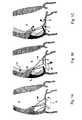
図1Aに示すように、心臓の僧帽弁(2)は、前方小葉(4)と後方小葉(6)とから構成されているものであって、心臓の主要ポンピングチャンバ(左心室(8))に対しての導入バルブである。僧帽弁(2)は、心室が収縮する際には、閉じられる。これにより、血液の逆流を防止する。心臓が収縮する際にこの僧帽弁が逆向きに動作しないよう、小葉(4,6)は、そのような向きの移動を防止し得るよう心臓の後壁(12)に対してアンカー止めされた複数の腱索(10)からなるネットワークによって、拘束されている。2つの乳頭筋(14)(一方の乳頭筋だけが図示されている)は、アンカー止め構造として機能する。 As shown in FIG. 1A, the mitral valve (2) of the heart is composed of an anterior leaflet (4) and a posterior leaflet (6), which is the main pumping chamber (left ventricle (8)) of the heart. ) Is an introduction valve. The mitral valve (2) is closed when the ventricle contracts. This prevents blood backflow. The leaflets (4, 6) are anchored to the posterior wall (12) of the heart to prevent movement in that direction so that the mitral valve does not move backwards as the heart contracts. It is restrained by a network composed of a plurality of chords (10). Two papillary muscles (14) (only one papillary muscle is shown) function as an anchoring structure.
冠状動脈に疾病を有していて心筋に対する血液供給が不十分であるような患者(例えば、虚血性心臓疾病および心臓発作)は、多くの場合、僧帽弁(2)の閉鎖不全を起こしやすい。すなわち、図1Bにおいて矢印(16)で示しているような、血液の漏洩または逆流を起こしやすい。閉鎖不全は、また、心筋が弱った患者(心筋症)や、全体的収縮不全を有した患者、においても起こる。そのような閉鎖不全は、身体に対しての前方血液流が減少することにより、および、肺に対しての負荷が大きくなることにより、運動能力を制限する。これにより、心不全の明らかな特徴としての疲労や息切れを引き起こす。修復しないと、閉鎖不全は、心臓発作や冠状動脈バイパス手術の後の死亡率を2倍とする。 Patients with coronary artery disease and inadequate blood supply to the myocardium (eg, ischemic heart disease and heart attack) are often prone to mitral regurgitation (2) . That is, blood leakage or backflow is likely to occur as shown by the arrow (16) in FIG. 1B. Incompetence also occurs in patients with weakened myocardium (cardiomyopathy) and patients with global systolic dysfunction. Such insufficiency limits athletic performance by reducing forward blood flow to the body and by increasing the load on the lungs. This causes fatigue and shortness of breath as distinct features of heart failure. Without repair, insufficiency doubles the mortality rate after a heart attack or coronary artery bypass surgery.
そのような機能的僧帽弁閉鎖不全症(mitral regurgitation,MR)は、基本的に、心室(8)の異常に関連している。それは、小葉(4,6)が構造的に正常であるからである。損傷した心筋は、例えば矢印(20)によって示されている向きに、膨出するすなわち外方へと膨らむ。この動きが乳頭筋(14)の直下に位置した壁セグメント(5)に影響を及ぼしたときには、拘束されている小葉(4,6)も、一緒に変位する。これにより、効果的に閉塞するという小葉の能力が制限され、閉鎖不全が発生する。 Such functional mitral regurgitation (MR) is basically associated with abnormalities in the ventricle (8). This is because the leaflets (4, 6) are structurally normal. The damaged myocardium bulges, ie bulges outward, for example in the direction indicated by the arrow (20). When this movement affects the wall segment (5) located directly below the papillary muscle (14), the constrained leaflets (4, 6) are also displaced together. This limits the ability of the leaflets to effectively occlude and causes failure of closure.
機能的MRに関する現在の治療法においては、僧帽小葉が挿入されている構造である僧帽弁輪のサイズを低減させる。しかしながら、僧帽弁輪のサイズの減少は、多くの場合、有効ではない。なぜなら、基本的な心臓壁変形を修正しないからである。そのため、僧帽弁小葉は、拘束されたままである。心臓壁の異常または変形が、経時的に進むことにより、僧帽弁輪のサイズ減少が初期的にはうまくいったとしても、多くの場合、その後に、再発してしまう。さらに、現在の手法においては、僧帽弁輪のサイズ低減に際し、患者を、心肺バイパス上に、配置する必要がある(心臓を停止させ、リングを挿入するために心臓を開く。その際、人工ポンプを使用することにより、心肺をバイパスする)。このこと自体が、付加的なリスクをもたらすとともに、外科医がこの手法を採用することを躊躇させる。 Current therapies for functional MR reduce the size of the mitral annulus, the structure in which the mitral leaflets are inserted. However, reducing the size of the mitral annulus is often not effective. This is because basic heart wall deformation is not corrected. As such, the mitral leaflet remains constrained. If abnormalities or deformities in the heart wall progress over time, even if the mitral annulus size reduction was initially successful, it often recurs afterwards. Furthermore, in current approaches, when reducing the size of the mitral annulus, the patient needs to be placed on cardiopulmonary bypass (the heart is stopped and the heart is opened to insert the ring. By using a pump, bypass the cardiopulmonary). This in itself poses additional risks and discourages surgeons from adopting this approach.
他の手法は、心筋の切除によってあるいは褶曲形成手術によってあるいは外部押圧デバイスによって、乳頭筋の直下に位置する損傷心室を再成形することである。しかしながら、このような技術は、心臓を開胸的に露出させることを必要とし、多くの場合、過度の外科的操作を必要とする。閉鎖不全の治療のために腱索形状を操作することに関して、努力がなされてきた、しかしながら、この手法は、一群をなす腱索を把持することによってあるいは熱印加によって腱索にかかる張力を増加させるものである。この手法は、腱索の長さを短くしてしまうものであり、本発明の目標とは正反対である。 Another approach is to reshape the damaged ventricle located directly under the papillary muscle by excision of the myocardium or by fold surgery or by an external pressing device. However, such techniques require the heart to be exposed open and often require excessive surgical manipulation. Efforts have been made regarding manipulating the chordae shape for the treatment of incompetence, however, this approach increases the tension on the chordae by grasping a group of chordae or by applying heat. Is. This technique shortens the length of the chord and is the opposite of the goal of the present invention.
よって、要望されていることは、心肺バイパスを必要とすることがないような、虚血性MRのための低侵襲的治療法である。なお、本出願人の知る限りにおいては、本出願に関連性を有する先行技術文献は存在しない。 Thus, what is needed is a minimally invasive treatment for ischemic MR that does not require cardiopulmonary bypass. To the best of the knowledge of the present applicant, there is no prior art document relevant to the present application.
本発明は、例えば乳頭筋や心臓壁筋肉といったような心筋に対して房室弁小葉を取り付けている腱索の拘束に基づいて、小葉の閉塞が制限されていることに関連した房室弁の閉鎖不全症を治療するための新規な方法および低侵襲的な方法を提供するものである。本発明による新規な経皮的カテーテルや他の新規なデバイスを使用すれば、胸部や心臓を切開する必要なく、治療を行うことができる。しかしながら、本発明は、経皮的手法に限定されるものではない。本発明によるデバイスおよび方法は、弁小葉と心臓壁との間の連結を修正する。以下の説明においては、僧帽弁の前方小葉を調節することに関するいくつかの特定の実施態様を参照するけれども、これらは単なる例示に過ぎない。本発明が、三尖弁の腱索や後方小葉の基底腱索や周縁腱索に対しても効果的であることは、理解されるであろう。本明細書においては、『基底』という用語は、小葉を心臓に対して基底近傍において(すなわち、ヒンジ領域)取り付けるために挿入されている腱索を意味しており、『』という用語は、小葉を心臓に対して基底近傍において取り付けるために挿入されている腱索を意味している、あるいは、弁の自由端すなわち周縁エッジから遠くにおいてこの領域の近傍において小葉を身体に対して取り付けるために挿入されている腱索を意味している。 The present invention relates to an atrioventricular valve associated with limited occlusion of a leaflet based on the restraint of the chordae attaching the atrioventricular leaflet to the myocardium, such as the papillary muscle and the heart wall muscle. It provides a novel and minimally invasive method for treating insufficiency. With the novel percutaneous catheter and other novel devices according to the present invention, treatment can be performed without the need to open the chest or heart. However, the present invention is not limited to the transcutaneous technique. The device and method according to the present invention modifies the connection between the valve leaflet and the heart wall. In the following description, reference will be made to some specific embodiments relating to adjusting the anterior leaflet of the mitral valve, but these are merely exemplary. It will be appreciated that the present invention is also effective for tricuspid chords, posterior lobular basal chords and peripheral chords. As used herein, the term “base” refers to a chord that has been inserted to attach a leaflet to the heart near the base (ie, the hinge region), and the term “” refers to the leaflet. Means chordae inserted to attach to the heart near the base, or inserted to attach a leaflet to the body in the vicinity of this region, far from the free or peripheral edge of the valve Means the chords that have been.
図1Bには、僧帽弁前方小葉(4)の基部に対して取り付けられたいくつかの腱索(11)(1つだけが図示されている)が示されており、小葉(4)を最大限に変形させている。有効なシールを形成するためには、小葉(4,6)が、延長上において互いに接触する必要がある。しかしながら、心臓壁(12)の変形に起因して腱索に対する張力が増大していることにより、前方小葉が変形しており、前方小葉の先端が、後方小葉に対して、ぎりぎり接触できる程度となっている。 FIG. 1B shows several chordae (11) (only one shown) attached to the base of the anterior mitral valve leaflet (4), with the leaflet (4) It is deformed to the maximum. In order to form an effective seal, the leaflets (4, 6) need to contact each other on the extension. However, due to the increased tension on the chordae due to the deformation of the heart wall (12), the anterior lobe is deformed, and the tip of the anterior lobe can barely contact the posterior lobe. It has become.
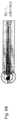
第1実施形態においては、本発明は、(図1Cに示すように)1つまたは複数の基底腱索(11)(周縁腱索ではない)を切断し、これにより、前方小葉(4)に関する曲がりを除去し、小葉(4,6)どうしがより正常な状態で当接できて、より効果的な閉塞をもたらし得るような、器具および方法を提供する。同時に、小葉の周縁すなわち自由端に関する腱索は、そのままとされ、閉塞に寄与する。この手法においては、必須ではないけれども、好ましくは、図2に示すように、心室の中心軸(19)寄りに位置しているような、前方小葉(4)に関する2つの腱索(11,13)を対称的に切断する。 In a first embodiment, the present invention cuts one or more basal chordae (11) (not the peripheral chordae) (as shown in FIG. 1C), thereby relating to the anterior leaflet (4). An instrument and method is provided that removes the bend and allows the leaflets (4,6) to abut in a more normal condition, resulting in a more effective occlusion. At the same time, the chords on the periphery of the leaflets, ie the free ends, are left intact and contribute to the occlusion. Although not essential in this approach, preferably, as shown in FIG. 2, the two chords (11, 13) associated with the anterior leaflet (4) as located near the central axis (19) of the ventricle. ) Cut symmetrically.
上述したように、切断プロセスは、新規な切断器具を使用して行われ、この切断器具は、切断対象をなす1つの腱索(あるいは、複数の腱索)の近傍位置へと、低侵襲的に位置決めされる。この位置決めに際しては、切断器具を前進させるための位置決めカテーテルを使用することができる。様々な実施形態において、切断器具は、左心室内へと連通する動脈系を逆行する経路や、静脈系を通って右心房へと入りさらに心房中隔を直接的に貫通して左心房内へと入る経路や、あるいは、胸壁および心膜内の小さな切開口を通した経皮的な経路、を経由して前進される。 As described above, the cutting process is performed using a novel cutting instrument that is minimally invasive to a position near one chord (or a plurality of chords) to be cut. Is positioned. For this positioning, a positioning catheter for advancing the cutting instrument can be used. In various embodiments, the cutting instrument is a path retrograde through the arterial system that communicates into the left ventricle, or through the venous system into the right atrium and directly through the atrial septum into the left atrium. It is advanced via a route to enter or a percutaneous route through a small incision in the chest wall and pericardium.
位置決めカテーテルは、選択された腱索を切断するための切断器具を挿通させる開口を備えている。例えば、カテーテルの端部は、開口したものとすることができ、切断器具の延出および引込を可能とすることができる。あるいは、ノッチを、カテーテルの端部の近傍に形成することができ、これにより、腱索に対しての切断器具のアクセスを可能とすることができる。好ましい実施形態においては、ノッチの横断面積は、腱索の一部を捕捉し得るような寸法および形状とすることができる。いくつかの構成においては、腱索の切断前には、部材または切断器具によって、腱索の一部を把持することができる。切断対象をなす腱索の一部を把持したりあるいは位置決めしたりするためのツールおよび方法に関するいくつかの実施形態については、後述する。 The positioning catheter includes an opening through which a cutting instrument for cutting selected chordae is inserted. For example, the end of the catheter can be open, allowing the cutting instrument to be extended and retracted. Alternatively, a notch can be formed near the end of the catheter, thereby allowing access of the cutting instrument to the chordae. In a preferred embodiment, the cross-sectional area of the notch can be sized and shaped to capture a portion of the chord. In some configurations, a portion of the chord can be grasped by the member or cutting instrument prior to cutting the chord. Several embodiments of tools and methods for grasping or positioning a portion of a chord to be cut will be described later.
ある種の実施形態においては、カテーテルの端部は、操縦可能とされる、および/または、予成形的に曲げが付与されている。これにより、例えば、後方小葉の腱索に対してアクセスすることができる。カテーテルの先端を操縦するための任意の公知の手法を、使用することができる。例えば、限定するものではないけれども、同軸的操縦ワイヤを使用することができる。 In certain embodiments, the end of the catheter is steerable and / or pre-shapedly bent. Thereby, for example, it is possible to access the chords of the posterior leaflet. Any known technique for manipulating the tip of the catheter can be used. For example, but not limited to, a coaxial steering wire can be used.
選択された腱索の切断は、様々な実施態様において様々な手段によって得られる。可能な手法には、例えば、切断対象をなす腱索の直径と比較して同等あるいはそれ以上の直径を有した切断ブレードや、蒸発除去用の光ファイバや、切断箇所に対してラジオ波エネルギーを案内するための手段、等がある。 Cutting selected chordae is obtained by various means in various embodiments. Possible methods include, for example, a cutting blade having a diameter equal to or larger than the diameter of the chord to be cut, an optical fiber for evaporative removal, and radio wave energy to the cutting site. There are means for guiding, etc.
本発明の他の実施形態においては、位置決めカテーテルは、切断対象をなす腱索の近傍位置にまで、導入カテーテルを使用して、搬送される。導入カテーテルは、好ましくは、位置決めカテーテルを一時的に安定化して保持し得る安定化手段を備え、これにより、切断器具を、切断対象をなす腱索に対して、位置決めすることができる。 In another embodiment of the present invention, the positioning catheter is delivered using an introducer catheter to a position near the chord to be cut. The introducer catheter preferably comprises stabilizing means that can temporarily stabilize and hold the positioning catheter so that the cutting instrument can be positioned relative to the chord to be cut.
腱索の領域および弁閉鎖不全領域に関しての心臓内外からの撮影を行うことにより、切断器具の適切な配置を容易としたり、また、手術の効果的な観測を行ったり、することができる。この撮影は、代替的には、超音波や磁気共鳴や光ファイバを使用して、行うこともできる。 By taking images of the chordae region and the valve regurgitation region from inside and outside the heart, it is possible to facilitate the proper placement of the cutting instrument and to perform effective observation of the operation. This imaging can alternatively be performed using ultrasound, magnetic resonance, or optical fiber.
さらに他の実施形態においては、本発明は、房室弁の閉鎖不全症を治療するための装置および方法であって、小葉の拘束を引き起こしている少なくとも1つの腱索を長尺化させるような装置および方法を提供する。以下の実施形態においては、長尺化対象をなす腱索に沿った複数の箇所に2つのノードを取り付け、これら2つのノードの間の位置において腱索を切断する。ノードに対しては、長さが調節可能とされた、あるいは、所定長さとされた、人工的腱索材料が連結されている。この人工的腱索材料は、ノードどうしの間において、実際に腱索を代替する。これにより、腱索が長尺化され、小葉と、乳頭筋または心筋と、の間の長さが調節される。ノードの位置決めのための器具や腱索の切断のための器具に関するいくつかの実施態様については、後述する。 In yet another embodiment, the present invention is an apparatus and method for treating atrioventricular valve insufficiency, such as elongating at least one chordae causing lobular restraint. Apparatus and methods are provided. In the following embodiment, two nodes are attached to a plurality of locations along the chord to be elongated, and the chord is cut at a position between these two nodes. An artificial chordal material whose length is adjustable or has a predetermined length is connected to the node. This artificial chordal material actually replaces chordae between nodes. This lengthens the chords and adjusts the length between the leaflets and the papillary or myocardium. Some embodiments relating to instruments for node positioning and chordal cutting are described below.
本発明ならびに本発明の他の目的に関する理解をより明瞭なものとするため、添付図面を参照しながら、以下に、詳細な説明を行う。 The following detailed description is made with reference to the accompanying drawings to provide a clearer understanding of the present invention and other objects of the present invention.
本発明の利点は、添付図面を参照しつつ、本発明を何ら限定するものではなく単なる例示としての好ましい実施形態に関する以下の詳細な説明を読むことにより、明瞭となるであろう。 The advantages of the present invention will become apparent upon reading the following detailed description of the preferred embodiments, which are not intended to limit the invention in any way, but merely as examples, with reference to the accompanying drawings.
以下、本発明の好ましい実施形態について、複数の図面を参照して説明する。 Hereinafter, preferred embodiments of the present invention will be described with reference to a plurality of drawings.
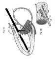
図3Bに示すように、本発明においては、経皮カテーテル(20)を使用する。このカテーテル(20)は、大動脈から左心室の導出領域(22)内へと逆行的に前進させることができる。このカテーテルは、標準的なガイドワイヤ手法(Seldinger 手法)を使用して、典型的には、腿の付け根のところの大動脈から、挿入することができる。このカテーテルは、予成形されたあるいは操作可能な曲がり部を備えている。このカテーテルは、例えば基底腱索(10)といったような切断対象をなす腱索の近傍にまで、切断器具(25)を運ぶことができる。基底腱索(10)は、カテーテル(20)がまず最初に出くわす腱索であって、図3Aに示す超音波画像写真に示すように、導出領域の直下に位置する腱索である。(カテーテルの先端は、例えば長手方向に延在した操縦ワイヤを使用して、操作することができる。)他の実施形態においては、複数の腱索が切断される。場合によっては、前方小葉に対して取り付けられた対をなす腱索(対称的なものまたはそうでないもの)を切断することが好ましいこともある。また、他の場合には、後方小葉に対して取り付けられた対をなす腱索を切断することが好ましいこともある。さらに他の場合には、各小葉からの腱索を切断することができる。切断すべき腱索の選択は、僧帽弁に関しての特定の変形形状に依存する。 As shown in FIG. 3B, a percutaneous catheter (20) is used in the present invention. The catheter (20) can be advanced retrogradely from the aorta into the exit region (22) of the left ventricle. The catheter can be inserted using the standard guidewire technique (Seldinger technique), typically from the aorta at the base of the thigh. The catheter has a pre-shaped or manipulatable bend. This catheter can carry the cutting instrument (25) to the vicinity of the chordae to be cut such as the basal chordae (10). The basal chord (10) is the chord that the catheter (20) first encounters, and is the chord that is located immediately below the lead-out area as shown in the ultrasonic image photograph shown in FIG. 3A. (The tip of the catheter can be manipulated using, for example, a longitudinally extending steering wire.) In other embodiments, multiple chords are cut. In some cases it may be preferable to cut a pair of chordae (symmetrical or not) attached to the anterior leaflet. In other cases, it may be preferable to cut a pair of chords attached to the posterior leaflet. In still other cases, the chords from each leaflet can be cut. The choice of chords to be cut depends on the particular deformed shape with respect to the mitral valve.
器具(25)は、まず最初に、腱索(10)を把持することができ、心臓の画像化によって、適切な腱索をターゲットとしているかどうかを検証する。例えば超音波といったような心臓の画像化は、また、大動脈から左心室(8)内へのカテーテルの挿入を案内するに際しても、使用することができる。このような手法は、ターゲットをなす腱索と、心室内へとカテーテルが進入する左心室導出領域と、の間の距離が近い(5mm以下)場合に有利である。この手法は、また、単純化されている。それは、処置中の状況で張力が増加しても、切断対象をなす腱索が、独立的に移動することがなく、剛直体としての心臓と一緒に並進移動するのみであるからである。 The instrument (25) can first grasp the chordae (10) and verify whether it is targeting the appropriate chordae by cardiac imaging. Imaging of the heart, such as ultrasound, can also be used to guide the insertion of the catheter from the aorta into the left ventricle (8). Such a method is advantageous when the distance between the target chord and the left ventricular lead-out region into which the catheter enters the ventricle is short (5 mm or less). This approach is also simplified. This is because, even if the tension increases in the situation during treatment, the chord to be cut does not move independently, but only translates together with the heart as a rigid body.
図4Aに示す実施形態においては、デバイスは、中空の円筒状カテーテル(20)とされており、このカテーテル(20)は、先端よりも手前のところに、ノッチ(24)を有している。開口の端面は、45°以上という角度でもって傾斜しており、これにより、腱索(10)を安定的に保持し得るという利点をもたらすことができる。腱索は、また、細いワイヤ(30)をカテーテルの先端側へと前進させることによっても、所定位置に保持することができる。細いワイヤ(30)は、事前に変形させておくことも、また、カテーテルの端部を利用して腱索へと戻ってくるような曲がり(26)を形成することも、できる。腱索(10)を把持するのに適したワイヤの他の変形が、可能である。例えば、鋭角〜直角といった曲がりや、V字形状、が可能である。この図は、好ましいフレキシブルなフックのみを示している。これにより、構造に対しての潜在的損傷可能性を避けることができる。他の形状であれば、把持可能性を高め得るかもしれないけれども、腱索を変位させてしまう可能性もある。 In the embodiment shown in FIG. 4A, the device is a hollow cylindrical catheter (20), which has a notch (24) in front of the tip. The end face of the opening is inclined at an angle of 45 ° or more, which can provide the advantage that the chords (10) can be stably held. The chords can also be held in place by advancing a thin wire (30) toward the distal end of the catheter. The thin wire (30) can be deformed in advance or can be bent (26) to return to the chord using the end of the catheter. Other variations of wire suitable for grasping the chordae (10) are possible. For example, a bend such as an acute angle to a right angle or a V shape is possible. This figure shows only the preferred flexible hook. This avoids potential damage to the structure. Other shapes may increase the gripping potential, but may displace the chordae.
ワイヤは、例えば超弾性的なニッケルチタン合金といったような形状記憶材料から構成することができる。ワイヤは、腱索の近傍の適切な位置にまでワイヤを前進させた時点で、自動的に所定形状となる。その後、ノッチ内に適合し得る形状とされた尖鋭なブレード(28)を、カテーテル内を通して前進させ、腱索を切断する。代替可能な実施形態においては、同じ機構を使用して、腱索を安定的に保持する。しかしながら、ブレードを使用することに代えて、標準的な光ファイバをカテーテル内を通して前進させ、強力なレーザーエネルギーを放出させる。これにより、腱索を切断する。他の実施形態においては、現在では異常な心臓構造を蒸発除去して治療するに際して通常的に使用されているようなラジオ周波数エネルギーを、カテーテル内を通して案内する。あるいは、囲みワイヤ(26)を使用して、腱索を切断する。 The wire can be composed of a shape memory material such as a superelastic nickel titanium alloy. The wire automatically assumes a predetermined shape when the wire is advanced to an appropriate position in the vicinity of the chord. A sharp blade (28) shaped to fit within the notch is then advanced through the catheter to cut the chordae. In an alternative embodiment, the same mechanism is used to hold the chords stably. However, instead of using a blade, a standard optical fiber is advanced through the catheter to emit powerful laser energy. As a result, the chords are cut. In other embodiments, radio frequency energy, such as is commonly used in currently evaporating and treating abnormal heart structures, is guided through the catheter. Alternatively, encircling wire (26) is used to cut the chord.
図4Bに示す実施形態においては、ワイヤ(26)を、開口したカテーテル先端(27)を超えて前進させ、このワイヤを使用することによって、腱索(10)を把持する。この場合にも、ワイヤ(26)は、弾性的な形状記憶材料から構成することができるとともに、例えば図示のフック形状といったよう予成形形状を有している。その後、腱索を、カテーテルの中空端部内へと引き込み、カテーテル内を通して前進させたブレード(28)またはレーザー光ファイバまたは蒸発除去用ラジオ波ワイヤを使用することにより、腱索を切断する。 In the embodiment shown in FIG. 4B, the chordae (10) is grasped by advancing the wire (26) beyond the open catheter tip (27) and using this wire. Also in this case, the wire (26) can be made of an elastic shape memory material and has a preformed shape such as the hook shape shown. The chordae are then cut by drawing them into the hollow end of the catheter and using a blade (28) advanced through the catheter or a laser optical fiber or evaporative radiowire.
図5に示す付加的な実施形態においては、ピンセット状のツールを使用することによって、腱索(10)を把持する。カテーテル(20)の端部には、2つの可動ジョー(30)が設けられている。これらジョーは、腱索を把持する。カテーテルを前進させることによって、腱索を、2つのジョーの間に形成されたスリット(31)の端部内へと受領することができる。腱索を安定的に保持し得るよう、さらに、腱索を切断可能とし得るよう、円形のまたは矩形のワイヤ(32)を、カテーテルの側方管腔内を通して前進させ、このワイヤによって、腱索の周囲を囲むとともに、2つのジョーの間に形成されたギャップ内に腱索を確実に拘束する。その後、尖鋭なブレード(28)またはレーザー光ファイバまたは蒸発除去用ラジオ波ワイヤを使用することにより、腱索を切断する。ブレードは、カテーテルの中央管腔から、腱索が保持されているジョー内へと、連通しているスリット(34)を通して前進させることができる。 In an additional embodiment shown in FIG. 5, the chords (10) are grasped by using a tweezer-like tool. Two movable jaws (30) are provided at the end of the catheter (20). These jaws grip the chords. By advancing the catheter, the chord can be received into the end of the slit (31) formed between the two jaws. A circular or rectangular wire (32) is advanced through the side lumen of the catheter so that the chords can be held stably and the chords can be cut, and this wire allows the chordae The chords are securely restrained within the gap formed between the two jaws. The chords are then cut by using a sharp blade (28) or laser optical fiber or evaporative removal radiowire. The blade can be advanced through the slit (34) in communication from the central lumen of the catheter and into the jaw where the chordae are held.
図6A〜図6Cに示すような他の実施形態においては、湾曲したペンチ状をなす2つの拘束部材を使用することにより、腱索を囲む。そして、2つのヒンジ(70)による回転駆動によって、腱索上にわたって円形をなすようにして拘束部材どうしを閉じる。その後、ブレード(28)またはレーザー光ファイバまたはラジオ波デバイスを、カテーテル内を通して拘束部材どうしの間へと前進させ、腱索を切断する。当業者であれば、切断前に腱索を把持するに際し、任意のタイプのピンセット状デバイスを使用し得ることは、理解されるであろう。 In other embodiments, such as those shown in FIGS. 6A-6C, the chords are surrounded by using two constraining members in the form of curved pliers. Then, the rotation of the two hinges (70) closes the restraining members so as to form a circle over the chordae. The blade (28) or laser optical fiber or radio wave device is then advanced through the catheter and between the restraining members to cut the chordae. One skilled in the art will appreciate that any type of tweezer-like device may be used in grasping the chords prior to cutting.
上述した各種の把持デバイスおよび切断デバイスは、また、図7Aに示す実施形態においても使用することができる。まず最初に、安定化用の導入カテーテル(18)を、左心室の頂点に向けて前進させる。その後、切断用のカテーテル(20)を、直接的にあるいは閉塞ゴムシールを有した案内アーム(36)を介して、導入カテーテル内のポートを通して前進させる。導入カテーテル(18)は、湾曲した当接部材(19)によって、安定化される。当接部材(19)は、カテーテルの先端を超えて延出されているとともに、心室頂点に対する接触を維持し得るような形状とされている。当接部材(19)は、実際に、弾性的な形状記憶材料から形成された複数の部材を備えて構成することができる。当接部材(19)は、カテーテルを超えて延出されたときには、湾曲した接触部分を形成する。この接触部分は、心室内の他の部分に対して接触することができる。導入カテーテル(18)は、ワイヤに沿って並進移動することができ、切断カテーテル(20)を、切断すべき腱索のところに、位置決めすることができる。 The various gripping and cutting devices described above can also be used in the embodiment shown in FIG. 7A. First, the stabilizing introducer catheter (18) is advanced toward the apex of the left ventricle. Thereafter, the cutting catheter (20) is advanced through a port in the introducer catheter, either directly or through a guide arm (36) with an occlusive rubber seal. The introducer catheter (18) is stabilized by a curved abutment member (19). The contact member (19) extends beyond the tip of the catheter and is shaped to maintain contact with the ventricular apex. The abutting member (19) can actually comprise a plurality of members formed from an elastic shape memory material. The abutment member (19) forms a curved contact portion when extended beyond the catheter. This contact portion can contact other portions of the ventricle. The introducer catheter (18) can be translated along the wire and the cutting catheter (20) can be positioned at the chord to be cut.
言うまでもないが、上記において例示した安定化機構は、前方僧帽弁小葉の基底腱索の近傍へと切断器具を位置決めするに際しての、単なる例示に過ぎない。安定化機構は、ワイヤや形状記憶材料に限定されるものではなく、また、単一の延出可能な接触部分に限定されるものでもない。例えば、実施形態によっては、複数の安定化脚や入れ子式伸縮機構などを使用することによって、周縁回りの複数箇所において左心室内部に接触することができる。 Of course, the stabilization mechanism illustrated above is merely illustrative in positioning the cutting instrument in the vicinity of the anterior mitochondrial basal chordae. The stabilization mechanism is not limited to wires or shape memory materials, nor is it limited to a single extendable contact portion. For example, in some embodiments, the left ventricle can be contacted at a plurality of locations around the periphery by using a plurality of stabilizing legs, a telescopic mechanism or the like.
切断カテーテルは、腱索に向けて操縦することができる。この場合、図7Bに示すようにして、導入カテーテル(18)を利用することが有利である。図7Bにおいては、切断カテーテルは、位置決めワイヤ(43,44,45,46)によって操縦される円筒形カラー(42)内を通して案内される。カラーを使用することなく、ワイヤ(43,46)を直接的に切断用カテーテル(20)に対して連結することも、可能である。例えばワイヤ(43)を引っ張りかつワイヤ(44)を緩めたときには、カテーテル(20)を、頂点に向かう向きに誘導することができる。これら2つのワイヤは、また、カラー(42)を介して連結して巻き取ることができる。当該技術分野において公知であるような他の操縦機構も、また、この目的に際して適切に使用することができる。例えば、切断カテーテルは、付加的に、導入カテーテル内に配置された任意の偏向機構によって操縦することができる。 The cutting catheter can be steered towards the chord. In this case, it is advantageous to utilize an introducer catheter (18) as shown in FIG. 7B. In FIG. 7B, the cutting catheter is guided through a cylindrical collar (42) that is steered by positioning wires (43, 44, 45, 46). It is also possible to connect the wires (43, 46) directly to the cutting catheter (20) without using a collar. For example, when the wire (43) is pulled and the wire (44) is loosened, the catheter (20) can be guided toward the apex. These two wires can also be connected and wound through a collar (42). Other steering mechanisms as are known in the art can also be used appropriately for this purpose. For example, the cutting catheter can additionally be steered by any deflection mechanism disposed within the introducer catheter.
プロセス全体の状況把握に際しては、画像撮影手法が必要とされる。この画像撮影手法においては、基底腱索を可視化することができ、切断前に把持デバイスによって把持している際の基底腱索の変形や変位を可視化することができる。 An image capturing method is required to grasp the status of the entire process. In this imaging method, the basal chords can be visualized, and the deformation and displacement of the basal chords when grasped by the grasping device before cutting can be visualized.
切断すべき腱索は、超音波によって容易に認識することができる。その理由は、切断すべき腱索が、小葉の周縁に位置した腱索と比較して太いからであり、また、患者内において明らかに動かないものであるからであり、さらに、左心室の導出領域に最も近いからである。超音波撮影は、隣接した右心室の導出領域内に配置された個別の心臓内エコー(ICE)カテーテル(市販品)を使用することによって、あるいは、ガイドカテーテル(18)内に組み込まれていて左心室自体の内部に配置された超音波トランスデューサ(40)を使用することによって、胸部表面からあるいは食道からあるいは心臓内から、行うことができる。心臓内からの手順の撮影は、導入用ガイドカテーテル(18)と切断カテーテル(20)とを備えている図7Aに示すような構成により可能とされる。この構成においては、ガイドカテーテル内において操縦される撮影デバイス(40)は、手術時には、腱索構造に関する高解像度の画像をもたらすことができ、同時に、僧帽弁小葉および閉鎖不全流を表示することもできる。この撮影デバイスは、2次元超音波マトリクスアレイから、あるいは、磁気共鳴コイルから、あるいは、米国特許第6,178,346号明細書に開示されているように血球周辺を通過できる近赤外エネルギーを送受信することができて3次元的可視画像をもたらし得る光ファイバから、構成することができる。この文献の記載内容は、参考のため、その全体がここに組み込まれる。3次元的超音波画像を得るために、複数の圧電性結晶からなる2次元マトリクスを使用することができる。あるいは、トランスデューサハウジング(40)内においてリニアフェーズドアレイを高速回転させ、これにより、3次元画像を得ることもできる。 The chord to be cut can be easily recognized by ultrasound. The reason for this is that the chords to be cut are thicker than the chords located at the periphery of the leaflets and because they do not move clearly in the patient. This is because it is closest to the area. Ultrasound imaging is performed by using a separate intracardiac echo (ICE) catheter (commercially available) placed in the exit region of the adjacent right ventricle, or incorporated into the guide catheter (18) and left This can be done from the chest surface or from the esophagus or from within the heart by using an ultrasound transducer (40) placed inside the ventricle itself. Imaging of the procedure from within the heart is made possible by a configuration as shown in FIG. 7A including an introduction guide catheter (18) and a cutting catheter (20). In this configuration, the imaging device (40) steered within the guide catheter can provide a high resolution image of the chordae structure during surgery, while simultaneously displaying mitral valve leaflets and incompetent flow You can also. This imaging device produces near infrared energy that can pass from a two-dimensional ultrasound matrix array, from a magnetic resonance coil, or around a blood cell as disclosed in US Pat. No. 6,178,346. It can consist of an optical fiber that can be transmitted and received and can provide a three-dimensional visible image. The contents of this document are incorporated herein in their entirety for reference. In order to obtain a three-dimensional ultrasonic image, a two-dimensional matrix composed of a plurality of piezoelectric crystals can be used. Alternatively, the linear phased array can be rotated at high speed in the transducer housing (40), thereby obtaining a three-dimensional image.
超音波撮影に基づき、後方僧帽弁小葉(図8Aにおいて符号(6)によって示されている)に対して連結されていて小葉の動きを顕著に制限している基底腱索を可視化し得ることは、注目に値する。小葉の動きは、また、乳頭筋(図8Bにおいて符号(14)によって示されている)に対してではなく、左心室後方壁(35)に対して連結されている壁腱索(33)によっても、制限されている。後方小葉(6)に対して連結されているこれら腱索は、左心室(8)内において動脈カテーテル(20)を前進させることによって、また、2つの乳頭筋の間を下向きに曲げ移動させることによって、近づくことができる。その際、可能であれば、形状記憶材料を補助的に使用することができる。この構成により、カテーテル先端の把持切断デバイスを、後方小葉上に挿入された腱索(33)に対して接近させることができる。撮影デバイス(40)は、プロセスの状況を把握し得るよう、カテーテルに沿って移動させることができる。これに代えて、カテーテルは、静脈系を介して挿入することができ、右心房から、心房中隔を横切って、図8Bに示すように左心房(39)内へと進入させることができる。その後、カテーテルを操作することにより、後方小葉腱索(33)を把持して切断する。 Based on ultrasound imaging, it can visualize the basal chordae connected to the posterior mitral valve leaflet (indicated by reference numeral (6) in FIG. 8A) and significantly restricting leaflet movement Is noteworthy. The leaflet movement is also due to the wall chords (33) connected to the left ventricular posterior wall (35) and not to the papillary muscle (indicated by reference (14) in FIG. 8B). Even limited. These chordae connected to the posterior leaflet (6) can bend and move downward between the two papillary muscles by advancing the arterial catheter (20) in the left ventricle (8). You can get closer. At that time, if possible, the shape memory material can be used supplementarily. With this configuration, the grasping and cutting device at the distal end of the catheter can be brought close to the chords (33) inserted on the posterior leaflets. The imaging device (40) can be moved along the catheter so that the status of the process can be ascertained. Alternatively, the catheter can be inserted through the venous system and can be advanced from the right atrium across the atrial septum and into the left atrium (39) as shown in FIG. 8B. Thereafter, by manipulating the catheter, the posterior lobule chord (33) is grasped and cut.
この手法は、まず最初に、生理学的な拍動流シミュレータ内において、ブタの僧帽弁の切除によって検証された。また、前方壁の梗塞によって急性的に引き起こされた機能的MRを有した7匹の羊に関するMRの除去においても、有効であった。また、慢性的な梗塞を有した7匹の羊に関しても、有効であった。5匹の羊に関しては平均で7ヶ月(最長で11ヶ月)の生存において、心室機能に関しての逆流や悪影響は、見られなかった。腱索を切断した2匹の羊は、急性の下壁梗塞を起こした。トロントジェネラルホスピタルの代表医師である Dr. Tirone David は、また、この手法を9人の患者に実施した。悪影響は見られず、僧帽弁の拘束の治療効果が示された。 This approach was first verified by excision of the porcine mitral valve in a physiological pulsatile flow simulator. It was also effective in removing MR for 7 sheep with functional MR acutely caused by anterior wall infarction. It was also effective for 7 sheep with chronic infarctions. There was no reflux or adverse effect on ventricular function in 5 sheep on average survival of 7 months (up to 11 months). Two sheep with cut chords had an acute inferior infarction. Dr. Tirone David, head of the Toronto General Hospital, also performed this procedure on nine patients. No adverse effects were seen, indicating the therapeutic effect of mitral valve restraint.
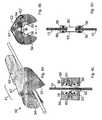
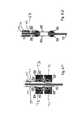
図9A〜図9Dに示すように、本発明のさらなる実施形態においては、選択した腱索を切断するのではなく、選択した腱索を引き伸ばす。継ぎ足しデバイス(58)が、基底腱索(より太い円柱状構造)上に挿入される。このデバイスは、半円形をなす2つのジョー(54)と、ヒンジ機構(61)と、を備えている。継ぎ足しプロセスの第1ステップにおいては、腱索の周囲においてジョーどうしを閉塞する。これを行うための一実施形態においては、ヒンジ機構(61)内において内側および外側に位置した1組をなす同軸ケーブルを備えている。各ケーブルは、ドアヒンジの場合と同様に、それぞれ対応するジョーに対して機械的に連結されている。ケーブルを互いに回転させることにより、腱索の周囲においてデバイスが閉塞される。この回転は、カテーテルの基端部に印加されたトルクによって得ることができる、あるいは、ヒンジ機構(61)内に圧縮スプリングを配置しておきその後スプリングに対しての機械的拘束を解放することによってケーブルどうしを回転させることができる。代替可能な実施形態(図9B)においては、2つの制御ケーブル(63,65)を使用する。ここで、制御ケーブル(63)は、ロッド(62)によって回転駆動されるようになっており、制御ケーブル(65)は、ロッド(64)によって回転駆動されるようになっている。図示のようにして両ロッドを回転させることにより、腱索の周囲においてデバイスを閉じることができる。逆向きにロッドを回転させれば、デバイスは解放される。両制御ロッドを回転駆動するためのギヤ付き機構によっても、同じ結果を得ることができる。 As shown in FIGS. 9A-9D, in a further embodiment of the invention, the selected chordae are stretched rather than cut. The augmentation device (58) is inserted over the basal chordae (thicker columnar structure). This device includes two jaws (54) having a semicircular shape and a hinge mechanism (61). In the first step of the splicing process, the jaws are occluded around the chord. One embodiment for doing this includes a set of coaxial cables located inside and outside the hinge mechanism (61). Each cable is mechanically connected to the corresponding jaw as in the case of the door hinge. By rotating the cables relative to each other, the device is occluded around the chord. This rotation can be obtained by the torque applied to the proximal end of the catheter, or by placing a compression spring in the hinge mechanism (61) and then releasing the mechanical restraint on the spring. The cables can be rotated. In an alternative embodiment (FIG. 9B), two control cables (63, 65) are used. Here, the control cable (63) is rotationally driven by the rod (62), and the control cable (65) is rotationally driven by the rod (64). The device can be closed around the chord by rotating both rods as shown. Rotating the rod in the opposite direction releases the device. The same result can be obtained by a geared mechanism for rotationally driving both control rods.
ジョー(54)は、腱索の周囲において、3つの構造を閉塞する。すなわち、2つのアンカー止めビードすなわちノード(56)と、1つの蒸発除去用ラジオ波コイル(62)と、を閉塞する。ビードすなわちノード(56)は、長尺セグメント(60)に対して連結されている。長尺セグメント(60)は、人工的腱索材料から形成されており、例えば、僧帽弁手術において多用されているような、Gortex(登録商標)(テトラフルオロエチレン)から形成されている。他の生体適合性かつ生体非吸収性の材料を使用することもできる。所定長さのこれら腱索(60)は、デバイスのケーシング内の凹所(58)内に収容されている。基底腱索の周囲においてジョーどうしを閉塞させた後に、腱索の両サイドにおいて、各ビードをなす半体どうしを、互いに恒久的に取り付ける(熱を使用して、あるいは、接着剤を使用して、あるいは、連結ペグを使用して)。その後、ラジオ波エネルギーを使用して、ビードどうしの間に位置した腱索部分を、切断する。切断デバイスに関連して上述したような他の切断手段を、ラジオ波による蒸発除去の代替手段として、使用することができる。 The jaw (54) occludes the three structures around the chord. That is, two anchoring beads or nodes (56) and one evaporative removal radio frequency coil (62) are closed. The bead or node (56) is connected to the elongated segment (60). The elongate segment (60) is formed from an artificial chordal material, eg, Gortex® (tetrafluoroethylene), such as commonly used in mitral valve surgery. Other biocompatible and non-bioabsorbable materials can also be used. These lengths of chords (60) are housed in recesses (58) in the casing of the device. After the jaws are occluded around the base chordae, the beaded halves are permanently attached to each other on both sides of the chordae (using heat or using adhesive) Or alternatively, using a connecting peg). Thereafter, using the radio wave energy, the chords located between the beads are cut. Other cutting means as described above in connection with the cutting device can be used as an alternative to evaporative removal by radio waves.
その後、デバイスの両ジョーを開き、図9Dに示すようにして、最終的な長尺腱索アセンブリを解放する。図9Dにおいては、2つのノードに対して連結された所定長さの人工的腱索(60)が、以前は短いものであった基底腱索(10)を引き伸ばしている。腱索材料の所望長さは、3次元超音波を使用することにより、乳頭筋先端と前方僧帽弁輪との間の連結距離が適切となるように、計算することができる。この連結距離(虚血性MRを有した患者においては増大される)と平均的正常値との間の相違を使用することによって、腱索長尺化に関する必要長さを計算することができる。これに代えて、この長さは、心エコー検査によって測定されたあるいは例えばMRIといったような他の撮影手法によって測定された心室寸法に基づき、下壁梗塞を有した患者あるいは全体的左心室膨出を起こした患者において確立されたノモグラフから、経験的に決定することができる。(ノードは、プラスチックやセラミクスやチタンも含めたような様々な材料から形成することができる。) The jaws of the device are then opened and the final elongated chordal assembly is released as shown in FIG. 9D. In FIG. 9D, a length of artificial chord (60) connected to two nodes stretches the previously short basal chord (10). The desired length of the chordal material can be calculated by using 3D ultrasound so that the connection distance between the papillary muscle tip and the anterior mitral annulus is appropriate. By using the difference between this connection distance (increased in patients with ischemic MR) and the average normal value, the required length for chordal lengthening can be calculated. Alternatively, this length is based on ventricular dimensions measured by echocardiography or by other imaging techniques such as MRI, or patients with lower wall infarction or global left ventricular bulge Can be determined empirically from nomographs established in patients who have had (Nodes can be made from a variety of materials, including plastic, ceramics, and titanium.)
いくつかの実施形態においては、所定長さの腱索(60)は、長尺化プロセス時に巻き取り可能なものとされる。これにより、ノード(56)どうしの間の距離を調節することができる。図9Eに示すように、ノード(56)を有したハウジングは、軸方向において互いに延伸可能とされた2つの部分(71,73)へと分離される。これにより、ノード(56)を腱索(10)に沿った任意の所望の位置に配置することができる。ノードどうしを連結している人工的腱索(60)は、ハウジング内に収容されている。ハウジング部分(71,73)によってノード(56)どうしが引き離されたときには、腱索材料が、基端寄りのハウジング部分(73)によって予備材料(75)から引っ張られる。予備材料(75)は、カテーテルの軸に沿って突出しており、カテーテル(69)に沿って延在しているチャネル(76)を通して突出している。処置対象をなす僧帽弁を観測することにより、所望の形状が形成されたかどうかが検証される。この時点で、長尺化/継ぎ足しが停止される。最後に、ワッシャや他のロック機構を使用することにより、新たな長さとされた腱索を所定に固定し、予備材料(75)を切断する。このプロセスは、図9Fおよび図9Gにおいて、より詳細に例示されている。図9Fにおいては、変位可能な2つのハウジング部分(71,73)が、互いに離間して示されている。ハウジング部分(71,73)どうしの間の人工的腱索(60)は、初期的な長さとされている。延長部分となる腱索材料(75)が、基端ビード(56)内のチャネルを通して、なおかつ、ハウジング部分(73)の基端面内に形成された小さなグルーブ(77)を通して、延在している。ビードどうしを互いに引き離すことができる。これにより、基端ビード(56)内のチャネルを挿通させることによって、2つのビード間における腱索材料の長さを増大させることができる。図9Gにおいては、カテーテルの主軸に沿って延在する予備材料(75)が、チャネル(76)を通って延在している様子が示されている。所望の腱索長さが得られた時点で、押込デバイス(81)が、チャネルの長さを通して進められる。押込デバイス(81)の先端には、ワッシャ(83)が設けられている。その後、蒸発除去用ラジオ波エネルギーや他の蒸発除去手段を使用することにより、押込デバイス(81)が、ビード
間の腱索セグメントと、予備材料(75)と、切断する。この時点で、ビードどうしは、長さ調節が済んで所定にロックされ終わった腱索材料(60)の分だけ、離間している。そして、ハウジングが開放され、カテーテルが引き抜かれる。In some embodiments, the length of chord (60) is rewound during the lengthening process. Thereby, the distance between nodes (56) can be adjusted. As shown in FIG. 9E, the housing with the node (56) is separated into two parts (71, 73) which are axially extensible. Thereby, a node (56) can be arrange | positioned in arbitrary desired positions along a chord (10). An artificial chord (60) connecting the nodes is housed in the housing. When the nodes (56) are pulled apart by the housing parts (71, 73), the chordal material is pulled from the preliminary material (75) by the proximal housing part (73). The preliminary material (75) protrudes along the axis of the catheter and protrudes through a channel (76) extending along the catheter (69). By observing the mitral valve that is a treatment target, it is verified whether a desired shape has been formed. At this point, the lengthening / addition is stopped. Finally, using a washer or other locking mechanism, the chords of the new length are fixed in place and the preliminary material (75) is cut. This process is illustrated in more detail in FIGS. 9F and 9G. In FIG. 9F, two displaceable housing parts (71, 73) are shown spaced apart from each other. The artificial chords (60) between the housing parts (71, 73) have an initial length. An extended chordal material (75) extends through a channel in the proximal bead (56) and through a small groove (77) formed in the proximal face of the housing portion (73). . The beads can be separated from each other. This can increase the length of the chordal material between the two beads by inserting a channel in the proximal bead (56). In FIG. 9G, the pre-material (75) extending along the main axis of the catheter is shown extending through the channel (76). Once the desired chord length is obtained, the pushing device (81) is advanced through the length of the channel. A washer (83) is provided at the tip of the pushing device (81). The pusher device (81) then cuts the chordal segment between the beads and the preliminary material (75) by using evaporative removal radio wave energy or other evaporative removal means. At this point, the beads are separated from each other by the length of the chord material (60) that has been adjusted in length and has been locked in place. The housing is then opened and the catheter is withdrawn.
本発明は、特に僧帽弁輪と言ったような僧帽弁小葉を過度に延ばしているような拘束機構の他端を短縮するための手術の付属器具として、使用することもできる。これは、虚血性MRの包括的修復に対する完全な経皮的アプローチをもたらす。 The present invention can also be used as a surgical accessory for shortening the other end of a restraining mechanism that over-extends the mitral leaflet, particularly the mitral annulus. This provides a complete percutaneous approach to comprehensive repair of ischemic MR.
上述したすべての切断デバイスや継ぎ足しデバイスの他の実施形態は、カテーテル内に収容することができる。また、案内アプローチに関する局所的撮影機構を使用すれば、交換前に、腱索に対する接触を検証することができる。撮影機構としては、超音波放出型圧電性結晶や、光学的コヒーレントトモグラフィーのための既存技術、がある。代替可能な実施形態においては、上述したようにしてレーザー切断を受けるべき腱索箇所に、レーザー受領効率を高めるような化合物を配置する。他の実施形態においては、腱索切断デバイスや継ぎ足しデバイスを、心臓手術時に拍動している心臓壁を介して挿入することができる、あるいは、例えば心膜ウィンドウを形成するために使用される小さな切開口といったような、ダイヤフラムおよび心膜内の小さな切開口を通して経皮的に挿入することができる。 Other embodiments of all the cutting devices and splicing devices described above can be housed within the catheter. Moreover, if the local imaging | photography mechanism regarding a guidance approach is used, the contact with respect to a chord can be verified before replacement | exchange. As an imaging mechanism, there are an ultrasonic emission type piezoelectric crystal and an existing technology for optical coherent tomography. In an alternative embodiment, a compound that enhances laser receiving efficiency is placed at the chord site to be subjected to laser cutting as described above. In other embodiments, a chordotomy device or an augmentation device can be inserted through the beating heart wall during cardiac surgery, or a small one used, for example, to form a pericardial window It can be inserted percutaneously through a diaphragm and a small incision in the pericardium, such as an incision.
遠隔操作ツール(ロボット手術)の低侵襲的光ファイバ映像案内という技術を使用することによっても、心肺バイパスを必要とすることなく、拍動している心臓内において、本発明による方法を実施することができる。しかしながら、場合によっては、プロセスを可視化する必要性のために、経皮的心肺バイパスの開始が必要となる(例えば、心臓の右側に連通する大動脈および静脈内において、バルーンを使用する場合)。その後、心臓キャビティは、清浄な流体(例えば、生理的食塩水や、ペルフルオロカーボン)によって灌流され、これにより、光ファイバを使用しての直接的可視化案内が可能とされる。 Implementing the method according to the invention in a beating heart without the need for cardiopulmonary bypass, even by using the technique of minimally invasive fiber optic image guidance of a remote control tool (robot surgery) Can do. However, in some cases, percutaneous cardiopulmonary bypass may need to be initiated due to the need to visualize the process (eg, when using a balloon in the aorta and veins that communicate to the right side of the heart). The heart cavity is then perfused with a clean fluid (eg, saline or perfluorocarbon), which allows direct visualization guidance using optical fibers.
LV(左心室)壁の局所的膨出を伴った下壁梗塞という特定の事例に関して説明したけれども、同じような僧帽弁変形は、全体的LV異常やLV膨出を有した患者においても存在する。そのような場合にも、同じ治療を受けるべきである。このことは、心臓切開手術を行うにはリスクがあるとともにMRの除去で恩恵を受けさらに低侵襲的な手法で過負荷の除去の恩恵を受けるような患者においては、特に重要である。 Although described for the specific case of lower wall infarction with local LV (left ventricular) wall bulge, similar mitral valve deformity is present in patients with global LV abnormalities and LV bulges To do. In such cases, you should receive the same treatment. This is particularly important in patients who are at risk of performing open heart surgery and who benefit from MR removal and benefit from removal of overload in a minimally invasive manner.
本発明によるデバイスは、また、リウマチ性の僧帽狭窄を有した患者に呈しても、適用することができる。これにより、特に現在までは限定的腱索構造を有した患者に効果が制限されていたような経皮的なバルーンを使用した僧帽弁形成手術といったような、リウマチ性の僧帽狭窄の他の経皮的治療の効果を促進することができる。 The device according to the invention can also be applied when presented to patients with rheumatic mitral stenosis. This allows other rheumatic mitral stenosis, such as mitral valvuloplasty using a percutaneous balloon, which has been limited to patients with limited chordal structures to date. The effect of percutaneous treatment can be promoted.
最後に、同様の手法は、本発明のカテーテルを、右心房および尖弁を通して挿入する場合に適用することができる。これにより、右心房が膨出した患者において、拘束されている尖弁を治療することができる。このことは、全体的心臓機能にとって有害であるとともに肝臓や先端に対しての血液逆流をもたらしてしまうような尖弁閉鎖不全症を救済することとなる。 Finally, a similar approach can be applied when the catheter of the present invention is inserted through the right atrium and cusp. This can treat a constrained cusp in a patient with a right atrium bulging. This saves a cusp insufficiency that is detrimental to overall heart function and can result in blood regurgitation to the liver and tip.
同じ技術または同様の技術は、また、診断や治療の目的のために、身体の他の部分においても使用することができる。例えば、腹腔鏡手術において使用することができ、これにより、胆管や尿管や他の構造ならびに胃腸管自体に関して、保持および治療を行うことができる。 The same or similar techniques can also be used in other parts of the body for diagnostic and therapeutic purposes. For example, it can be used in laparoscopic surgery, which allows retention and treatment of bile ducts, ureters and other structures and the gastrointestinal tract itself.
上記においては、ある種の好ましい実施形態に関して説明したけれども、上記説明は、例示のためのものに過ぎない。当業者には、本発明の精神の範囲を逸脱することなく、様々な変形や他の実施態様とし得ることが自明であろう。上記例示における細部は、本発明の原理を逸脱することなく、変形することができる。そのような修正や変形も、また、本発明の精神および範囲内に属することが意図されている。 Although described above with respect to certain preferred embodiments, the above description is for illustrative purposes only. It will be apparent to those skilled in the art that various modifications and other embodiments can be made without departing from the spirit of the invention. Details in the above examples can be modified without departing from the principles of the invention. Such modifications and variations are also intended to fall within the spirit and scope of the present invention.
6 後方小葉
10 基底腱索
18 導入カテーテル
19 当接部材
20 経皮カテーテル(位置決めカテーテル)
24 ノッチ
25 切断器具
28 ブレード
30 ワイヤ
40 超音波トランスデューサ、撮影デバイス
43 位置決めワイヤ
44 位置決めワイヤ
45 位置決めワイヤ
46 位置決めワイヤ
54 ジョー
56 ノード
58 継ぎ足しデバイス(長尺化デバイス)
60 長尺セグメント(人工的腱索材料)
61 ヒンジ機構
62 蒸発除去用ラジオ波コイル
63 制御ケーブル
65 制御ケーブル
70 ヒンジ6
24
60 Long segment (artificial chord material)
61
Claims (55)
Translated fromJapanese房室弁小葉を心臓内筋肉に対して取り付けている少なくとも1つの腱索を切断するための切断器具と;
この切断器具を前記少なくとも1つの腱索の近傍に配置するための位置決めカテーテルであるとともに、前記少なくとも1つの腱索を切断するための前記切断器具を挿通させる開口を備えた位置決めカテーテルと;
を具備していることを特徴とする装置。A device for treating atrioventricular insufficiency, comprising:
A cutting instrument for cutting at least one chordae attaching the atrioventricular leaflet to the intracardiac muscle;
A positioning catheter for positioning the cutting instrument in the vicinity of the at least one chord and an opening through which the cutting instrument for cutting the at least one chord is inserted;
The apparatus characterized by comprising.
前記切断器具が、ブレードを有し、
このブレードの切断エッジの直径が、前記少なくとも1つの腱索の直径とほぼ同じとされていることを特徴とする装置。The apparatus of claim 1.
The cutting instrument has a blade;
The diameter of the cutting edge of the blade is substantially the same as the diameter of the at least one chord.
前記切断器具が、蒸発除去用のレーザーエネルギーを搬送するための光ファイバを有していることを特徴とする装置。The apparatus of claim 1.
The apparatus characterized in that the cutting instrument has an optical fiber for carrying the laser energy for evaporative removal.
前記切断器具が、ラジオ波周波数電極を有していることを特徴とする装置。The apparatus of claim 1.
A device wherein the cutting instrument has a radio frequency electrode.
前記カテーテルが、後方小葉に対して取り付けた腱索に対して適切に係合し得るようにして湾曲していることを特徴とする装置。The apparatus of claim 1.
A device wherein the catheter is curved so that it can properly engage a chord attached to the posterior leaflet.
前記カテーテルが、操縦可能な先端を有していることを特徴とする装置。The apparatus of claim 1.
A device wherein the catheter has a steerable tip.
前記カテーテルが、さらに、前記カテーテル先端を操縦し得るよう、同軸的操縦ワイヤを有していることを特徴とする装置。The apparatus of claim 6.
The apparatus further comprising a coaxial steering wire so that the catheter tip can be steered.
前記切断器具が、前記開口を通して逆向きに延出可能なものとされ、
前記開口が、前記少なくとも1つの腱索の近傍において、前記カテーテルの端部に位置していることを特徴とする装置。The apparatus of claim 1.
The cutting instrument is capable of extending in the reverse direction through the opening;
The device, wherein the opening is located at an end of the catheter in the vicinity of the at least one chord.
前記開口が、前記カテーテル内に形成されたノッチを有し、
このノッチの横断面積が、前記少なくとも1つの腱索の横断面積よりも大きいことを特徴とする装置。The apparatus of claim 1.
The opening has a notch formed in the catheter;
The cross-sectional area of the notch is larger than the cross-sectional area of the at least one chord.
前記ノッチが、前記少なくとも1つの腱索が前記ノッチ内に配置されたときに前記少なくとも1つの腱索の移動を制限し得るよう、前記ノッチの一部を形成するものとして少なくとも1つの突出エッジを有していることを特徴とする装置。The apparatus of claim 9.
At least one protruding edge as forming part of the notch so that the notch can limit movement of the at least one chord when the at least one chord is placed in the notch A device characterized by comprising.
前記切断器具が、さらに、前記少なくとも1つの腱索を把持するための把持手段を備えていることを特徴とする装置。The apparatus of claim 1.
The apparatus characterized in that the cutting instrument further comprises gripping means for gripping the at least one chord.
前記把持手段が、さらに、ワイヤを有し、
このワイヤが、前記少なくとも1つの腱索を部分的に包囲し得るように変形した端部を有していることを特徴とする装置。The apparatus of claim 11.
The gripping means further comprises a wire;
A device characterized in that the wire has an end that is deformed so as to partially surround the at least one chord.
前記ワイヤが、生体温度においてまたは生体温度近傍において変形するような形状記憶材料から形成されていることを特徴とする装置。The apparatus of claim 12.
The device is characterized in that the wire is formed of a shape memory material that deforms at or near the living body temperature.
前記把持手段が、前記開口を通して逆向きに延出可能なものとされ、
前記開口が、前記少なくとも1つの腱索の近傍において、前記カテーテルの端部に位置しており、
これにより、把持した前記腱索を、前記開口に向けて引き込み得るものとなっていることを特徴とする装置。The apparatus of claim 11.
The gripping means can extend in the reverse direction through the opening;
The opening is located at the end of the catheter in the vicinity of the at least one chord;
Thereby, the grasped chord is capable of being pulled toward the opening.
さらに、一対をなす操作可能なジョーを具備し、
これらジョーが、前記少なくとも1つの腱索を把持し得るよう、前記少なくとも1つの腱索の近傍において、前記カテーテルの端部に配置されていることを特徴とする装置。The apparatus of claim 1.
Furthermore, it has a pair of operable jaws,
A device characterized in that the jaws are arranged at the end of the catheter in the vicinity of the at least one chord so that it can grip the at least one chord.
さらに、一対をなす回転可能なペンチを具備し、
これらペンチが、これらペンチを閉じることによって前記少なくとも1つの腱索を拘束し得るよう、前記少なくとも1つの腱索の近傍において、前記カテーテルの端部に配置されていることを特徴とする装置。The apparatus of claim 1.
Furthermore, it has a pair of rotatable pliers,
A device characterized in that the pliers are arranged at the end of the catheter in the vicinity of the at least one chord so that the at least one chord can be restrained by closing the pliers.
さらに、前記位置決めカテーテルを前記少なくとも1つの腱索に向けて前進させ得るよう、導入カテーテルを具備していることを特徴とする装置。The apparatus of claim 1.
The apparatus further comprises an introducer catheter so that the positioning catheter can be advanced toward the at least one chord.
前記導入カテーテルが、さらに、案内アームを備え、
この案内アームを通して、前記少なくとも1つの腱索の近傍位置にまで前記位置決めカテーテルが操作されるようになっていることを特徴とする装置。The apparatus of claim 17.
The introduction catheter further comprises a guide arm;
The positioning catheter is operated through the guide arm to a position near the at least one chord.
前記導入カテーテルが、心室内において前記導入カテーテルを一時的に安定化して保持し得る安定化手段を備えていることを特徴とする装置。The apparatus of claim 17.
The introduction catheter is provided with a stabilizing means capable of temporarily stabilizing and holding the introduction catheter in the ventricle.
前記安定化手段が、1つまたは複数の当接部材を有し、
このまたはこれら当接部材が、前記導入カテーテルから逆向きに延出可能とされ、これにより、1つまたは複数のポイントにおいて心臓キャビティの内表面に対して当接し得るものとされていることを特徴とする装置。The apparatus of claim 19, wherein
The stabilizing means comprises one or more abutment members;
This or these abutment members can be extended in the opposite direction from the introducer catheter so that they can abut against the inner surface of the heart cavity at one or more points. Equipment.
前記当接部材が、弾性的な形状記憶材料から形成され、
前記当接部材が、前記導入カテーテルから延出された際には、所望の形状をなすことを特徴とする装置。The apparatus of claim 20.
The abutment member is formed from an elastic shape memory material;
The device according to claim 1, wherein the contact member has a desired shape when extended from the introduction catheter.
さらに、前記導入カテーテル上に、前記少なくとも1つの腱索の近傍領域を撮影し得る超音波トランスデューサを備えていることを特徴とする装置。The apparatus of claim 17.
The apparatus further includes an ultrasonic transducer capable of imaging a region near the at least one chord on the introduction catheter.
前記位置決めカテーテルが、前記導入カテーテルに形成された開口を通して、前記導入カテーテルから突出し、
前記導入カテーテルから同様にして突出する複数の位置決めワイヤが設けられ、
これら複数の位置決めワイヤが、前記位置決めカテーテルに対して取り付けられ、
1つまたは複数の位置決めワイヤに張力を印加することによって、前記位置決めワイヤの端部の操縦が可能とされていることを特徴とする装置。The apparatus of claim 17.
The positioning catheter protrudes from the introducer catheter through an opening formed in the introducer catheter;
A plurality of positioning wires protruding in the same manner from the introduction catheter are provided,
These multiple positioning wires are attached to the positioning catheter,
An apparatus wherein the end of the positioning wire is steerable by applying tension to one or more positioning wires.
前記導入カテーテルが、さらに、撮影デバイスを備え、
この撮影デバイスが、前記少なくとも1つの腱索も含めた前記房室弁の近傍領域を撮影し得るような向きとされていることを特徴とする装置。The apparatus of claim 17.
The introduction catheter further comprises an imaging device;
The apparatus is characterized in that the photographing device is oriented so as to photograph a region near the atrioventricular valve including the at least one chord.
前記撮影デバイスが、複数の圧電性結晶からなる2次元マトリクスアレイと、3次元画像を得るために前記カテーテル内において回転させる手段が付設されたリニアフェーズドアレイと、磁気共鳴コイルと、近赤外エネルギーを送受信することができる光ファイバと、からなるグループの中から選択された撮影機を備えていることを特徴とする装置。The apparatus of claim 24.
The imaging device includes a two-dimensional matrix array composed of a plurality of piezoelectric crystals, a linear phased array provided with means for rotating in the catheter to obtain a three-dimensional image, a magnetic resonance coil, and a near infrared energy And an optical fiber capable of transmitting and receiving an image, and a camera selected from the group consisting of:
房室弁小葉を心臓内筋肉に対して取り付けている少なくとも1つの腱索を経皮的に切断することを特徴とする方法。A method for treating atrioventricular valve insufficiency associated with restricting lobular obstruction by lobular restraint, comprising:
A method comprising percutaneously cutting at least one chordae attaching an atrioventricular leaflet to an intracardiac muscle.
前記切断を行う前に、前記少なくとも1つの腱索を把持することを特徴とする方法。The method of claim 26.
Grasping the at least one chord before performing the cutting.
前記少なくとも1つの腱索を、基底腱索とすることを特徴とする方法。The method of claim 26.
The method wherein the at least one chord is a basal chord.
前記少なくとも1つの腱索を、2つの腱索とし、
第1の腱索を、前方小葉に対して取り付けられたものとし、
第2の腱索を、後方小葉に対して取り付けられたものとすることを特徴とする方法。The method of claim 26.
The at least one chord is two chords,
The first chord is attached to the anterior leaflet;
The second chord is attached to the posterior leaflet.
前記少なくとも1つの腱索を、一対をなす2つの腱索とすることを特徴とする方法。The method of claim 26.
The method wherein the at least one chord is a pair of two chords.
前記一対をなす2つの腱索を、心室の中心軸に対して最も近くに位置した前方小葉に対して取り付けられた2つの腱索とすることを特徴とする方法。The method of claim 30, wherein
The two chords forming the pair are two chords attached to the anterior leaflet located closest to the central axis of the ventricle.
カテーテルを介することにより、前記少なくとも1つの腱索の近傍に、切断デバイスを位置決めすることを特徴とする方法。The method of claim 26.
A method of positioning a cutting device in the vicinity of said at least one chord via a catheter.
前記位置決めステップにおいては、左心室内へと連通する動脈系を逆行する経路と、静脈系を通って右心房へと入りさらに心房中隔を直接的に貫通して左心房内へと入る経路と、胸壁および心膜内の小さな切開口を通した経皮的な経路と、からなるグループの中から選択された経路を経由して前記切断デバイスを前進させることを特徴とする方法。The method of claim 32, wherein
In the positioning step, a path that reverses the arterial system communicating with the left ventricle, a path that enters the right atrium through the venous system, and directly penetrates the atrial septum and enters the left atrium. Advancing the cutting device via a route selected from the group consisting of: a percutaneous route through a small incision in the chest wall and pericardium;
前記前進ステップを、ロボットツールを経皮的に使用することによって補助することを特徴とする方法。The method of claim 32, wherein
A method of assisting the advance step by using a robotic tool percutaneously.
さらに、前記切断プロセスの前においておよび最中において、前記少なくとも1つの腱索を含む心臓領域を撮影することを特徴とする方法。The method of claim 26.
Furthermore, before and during the cutting process, the method comprises imaging a cardiac region containing the at least one chord.
前記撮影に際しては、前記心臓領域に対して超音波エネルギーを送信することを特徴とする方法。36. The method of claim 35, wherein
In the imaging, ultrasonic energy is transmitted to the heart region.
前記超音波エネルギーを、胸部表面からあるいは食道からあるいは心臓内から送信することを特徴とする方法。The method of claim 36, wherein
A method of transmitting the ultrasonic energy from the chest surface, from the esophagus, or from within the heart.
前記心臓内から送信される前記超音波エネルギーを、前記少なくとも1つの腱索の近傍に配置された超音波トランスデューサから得ることを特徴とする方法。38. The method of claim 37, wherein
A method of obtaining the ultrasonic energy transmitted from within the heart from an ultrasonic transducer disposed in the vicinity of the at least one chord.
前記撮影に際しては、1つまたは複数の光ファイバを使用して、付加的に、前記心臓領域の撮影を行うことを特徴とする方法。36. The method of claim 35, wherein
In the imaging, the cardiac region is additionally imaged by using one or a plurality of optical fibers.
前記超音波トランスデューサを、前記少なくとも1つの腱索の近傍に配置することを特徴とする方法。36. The method of claim 35, wherein
A method of placing the ultrasonic transducer in the vicinity of the at least one chord.
房室弁小葉を心臓内筋肉に対して取り付けている少なくとも1つの腱索を長尺化させるための長尺化器具と;
この長尺化器具を前記少なくとも1つの腱索の近傍に搬送するための搬送手段と;
を具備していることを特徴とする装置。A device for treating atrioventricular insufficiency, comprising:
An elongating device for elongating at least one chordae attaching an atrioventricular leaflet to an intracardiac muscle;
Transport means for transporting the elongated instrument to the vicinity of the at least one chord;
The apparatus characterized by comprising.
前記長尺化器具が、
2つのノードと;
これらノードに対して連結された所定長さの少なくとも1つの人工的腱索材料と;
前記少なくとも1つの腱索に沿ったそれぞれの所定位置に各ノードを固定するための固定手段と;
固定された前記2つのノードの間において前記少なくとも1つの腱索の一部を切断するための切断手段と;
を備えていることを特徴とする装置。42. The apparatus of claim 41.
The lengthening device is
Two nodes;
At least one artificial chordal material of a predetermined length connected to these nodes;
Fixing means for fixing each node at a predetermined position along the at least one chord;
Cutting means for cutting a portion of the at least one chord between the two fixed nodes;
A device characterized by comprising:
さらに、前記少なくとも1つの所定長さの人工的腱索材料の長さを調節するための調節手段を具備していることを特徴とする装置。42. The apparatus of claim 41.
The apparatus further comprises adjusting means for adjusting the length of the at least one predetermined length of artificial chordal material.
前記切断手段が、ラジオ波電極と、ブレードと、蒸発除去用のレーザーエネルギーを搬送するための光ファイバと、からなるグループの中から選択された手段を有していることを特徴とする装置。43. The apparatus of claim 42.
The apparatus characterized in that the cutting means comprises means selected from the group consisting of a radio wave electrode, a blade, and an optical fiber for carrying laser energy for evaporative removal.
前記各ノードが、第1係合部分と第2係合部分とを備え、
これら係合部分が、前記少なくとも1つの腱索の一部を受領するための凹所を有し、
前記各ノードを固定するための前記固定手段が、前記各係合部分の表面に対して適用された接着剤と、前記各係合部分上にそれぞれ対応した配置された複数の連結ペグおよび複数の孔と、各係合部分を一緒にアニールするための加熱ブレードと、からなるグループの中から選択された手段を有していることを特徴とする装置。43. The apparatus of claim 42.
Each node comprises a first engagement portion and a second engagement portion;
The engaging portions have a recess for receiving a portion of the at least one chord;
The fixing means for fixing each node includes an adhesive applied to the surface of each engaging portion, a plurality of connecting pegs respectively arranged on each engaging portion, and a plurality of connecting pegs An apparatus having means selected from the group consisting of a hole and a heating blade for annealing each engaging portion together.
前記長尺化器具が、2つのノードを備え、
これら各ノードが、2つの係合部分とを備え、
これら係合部分が、前記少なくとも1つの腱索の一部を受領するための凹所を有し、
前記長尺化器具が、
前記2つのノードに対して連結された所定長さの少なくとも1つの人工的腱索材料と;
前記少なくとも1つの腱索に沿ったそれぞれの所定位置に各ノードを固定するための固定手段と;
固定された前記2つのノードの間において前記少なくとも1つの腱索の一部を切断するための切断手段と;
を備え、
前記搬送手段が、
2つのジョーであるとともに、各ノードの前記2つの係合部分のそれぞれ対応する係合部分に収容され、少なくとも一方のジョーが、前記所定長さの少なくとも1つの人工的腱索材料を収容しているような、2つのジョーと;
これら2つのジョーを回転可能とする制御可能なヒンジ機構と;
前記ジョーと前記ヒンジ機構と前記長尺化器具とを前記少なくとも1つの腱索の近傍位置にまで搬送するためのカテーテルと;
を備えていることを特徴とする装置。42. The apparatus of claim 41.
The lengthening instrument comprises two nodes;
Each of these nodes comprises two engaging portions,
The engaging portions have a recess for receiving a portion of the at least one chord;
The lengthening device is
At least one artificial chordal material of a predetermined length connected to the two nodes;
Fixing means for fixing each node at a predetermined position along the at least one chord;
Cutting means for cutting a portion of the at least one chord between the two fixed nodes;
With
The conveying means is
Two jaws and accommodated in corresponding engagement portions of each of the two engagement portions of each node, wherein at least one jaw contains at least one artificial chordal material of the predetermined length. With two Joes like
A controllable hinge mechanism that allows these two jaws to rotate;
A catheter for delivering the jaw, the hinge mechanism and the lengthening instrument to a position proximate to the at least one chord;
A device characterized by comprising:
房室弁小葉を心臓内筋肉に対して取り付けている少なくとも1つの腱索を長尺化させることを特徴とする方法。A method for treating atrioventricular valve insufficiency associated with restricting lobular obstruction by lobular restraint, comprising:
Elongating at least one chordae attaching an atrioventricular leaflet to an intracardiac muscle.
前記長尺化ステップにおいては、
前記少なくとも1つの腱索の近傍位置にまで、所定長さの人工的腱索材料によって互いに連結された2つのノードを、搬送し;
前記少なくとも1つの腱索に対して前記2つのノードを固定し;
前記2つのノードの間の位置において、前記少なくとも1つの腱索を切断する;
ことを特徴とする方法。48. The method of claim 47, wherein
In the lengthening step,
Transporting two nodes connected to each other by a length of artificial chordal material to a position proximate to the at least one chordae;
Fixing the two nodes to the at least one chord;
Cutting the at least one chordae at a position between the two nodes;
A method characterized by that.
さらに、前記所定長さの人工的腱索材料の長さを調節することを特徴とする方法。49. The method of claim 48, wherein
And adjusting the length of the artificial chord material of the predetermined length.
前記切断ステップにおいては、前記2つのノードの間において前記少なくとも1つの腱索に対してラジオ波エネルギーを印加することを特徴とする方法。49. The method of claim 48, wherein
In the cutting step, radio wave energy is applied to the at least one chord between the two nodes.
前記各ノードの固定ステップにおいては、さらに、
第1係合部分と第2係合部分との間において前記少なくとも1つの腱索の一部を包囲し;
前記第1係合部分を前記第2係合部分に対して接着する;
ことを特徴とする方法。49. The method of claim 48, wherein
In the fixing step of each node,
Enclosing a portion of the at least one chord between the first engagement portion and the second engagement portion;
Bonding the first engagement portion to the second engagement portion;
A method characterized by that.
前記接着ステップにおいては、前記両係合部分の表面どうしをアニールするために熱を印加することを特徴とする方法。52. The method of claim 51, wherein
In the bonding step, heat is applied to anneal the surfaces of the engaging portions.
前記接着ステップにおいては、前記両係合部分の表面に対して適用された接着剤を硬化させることを特徴とする方法。52. The method of claim 51, wherein
In the bonding step, the adhesive applied to the surfaces of the engaging portions is cured.
前記接着ステップにおいては、前記両係合部分を互いに押圧し、これにより、各係合部分のそれぞれの表面にそれぞれ対応して配置された複数のペグと複数の孔とを相互連結させることを特徴とする方法。52. The method of claim 51, wherein
In the bonding step, the engaging portions are pressed against each other, thereby interconnecting a plurality of pegs and a plurality of holes arranged corresponding to the respective surfaces of the engaging portions. And how to.
前記搬送ステップにおいては、さらに、前記2つのノードを収容したヒンジハウジングを、導入カテーテルを使用して、左心室内へと連通する動脈系を逆行する経路と、静脈系を通って右心房へと入りさらに心房中隔を直接的に貫通して左心房内へと入る経路と、胸壁および心膜内の小さな切開口を通した経皮的な経路と、からなるグループの中から選択された経路を経由して、前進させることを特徴とする方法。48. The method of claim 47, wherein
In the transport step, the hinge housing containing the two nodes is further routed using an introducer catheter to reverse the arterial system communicating with the left ventricle and through the venous system to the right atrium. A route selected from the group consisting of: a route directly through the atrial septum into the left atrium and a percutaneous route through a small incision in the chest wall and pericardium A method characterized by advancing via
Applications Claiming Priority (3)
| Application Number | Priority Date | Filing Date | Title |
|---|---|---|---|
| US40015102P | 2002-08-01 | 2002-08-01 | |
| US60/400,151 | 2002-08-01 | ||
| PCT/US2003/024367WO2004012583A2 (en) | 2002-08-01 | 2003-08-01 | Cardiac devices and methods for minimally invasive repair of ischemic mitral regurgitation |
Publications (3)
| Publication Number | Publication Date |
|---|---|
| JP2005534426Atrue JP2005534426A (en) | 2005-11-17 |
| JP2005534426A5 JP2005534426A5 (en) | 2006-10-05 |
| JP4808964B2 JP4808964B2 (en) | 2011-11-02 |
Family
ID=31495797
Family Applications (1)
| Application Number | Title | Priority Date | Filing Date |
|---|---|---|---|
| JP2004526409AExpired - LifetimeJP4808964B2 (en) | 2002-08-01 | 2003-08-01 | Heart device and method for minimally invasive repair of ischemic mitral regurgitation |
Country Status (6)
| Country | Link |
|---|---|
| US (1) | US8292884B2 (en) |
| EP (1) | EP1545371B1 (en) |
| JP (1) | JP4808964B2 (en) |
| AU (1) | AU2003265354A1 (en) |
| CA (1) | CA2494758C (en) |
| WO (1) | WO2004012583A2 (en) |
Cited By (2)
| Publication number | Priority date | Publication date | Assignee | Title |
|---|---|---|---|---|
| WO2007102586A1 (en)* | 2006-03-09 | 2007-09-13 | Olympus Medical Systems Corp. | Treatment instrument for endoscope |
| JP2019511332A (en)* | 2016-04-12 | 2019-04-25 | ラース エリクソン, | Minimally invasive atrioventricular valve treatment with tendon adjustment |
Families Citing this family (220)
| Publication number | Priority date | Publication date | Assignee | Title |
|---|---|---|---|---|
| EP2133030A1 (en) | 1997-06-27 | 2009-12-16 | The Trustees of Columbia University of the City of New York | Method and apparatus for circulatory valve repair |
| FR2768324B1 (en) | 1997-09-12 | 1999-12-10 | Jacques Seguin | SURGICAL INSTRUMENT FOR PERCUTANEOUSLY FIXING TWO AREAS OF SOFT TISSUE, NORMALLY MUTUALLY REMOTE, TO ONE ANOTHER |
| US10327743B2 (en) | 1999-04-09 | 2019-06-25 | Evalve, Inc. | Device and methods for endoscopic annuloplasty |
| US7226467B2 (en) | 1999-04-09 | 2007-06-05 | Evalve, Inc. | Fixation device delivery catheter, systems and methods of use |
| US6752813B2 (en) | 1999-04-09 | 2004-06-22 | Evalve, Inc. | Methods and devices for capturing and fixing leaflets in valve repair |
| AU770243B2 (en) | 1999-04-09 | 2004-02-19 | Evalve, Inc. | Methods and apparatus for cardiac valve repair |
| US6575971B2 (en) | 2001-11-15 | 2003-06-10 | Quantum Cor, Inc. | Cardiac valve leaflet stapler device and methods thereof |
| US20080249504A1 (en) | 2007-04-06 | 2008-10-09 | Lattouf Omar M | Instrument port |
| US6978176B2 (en)* | 2001-12-08 | 2005-12-20 | Lattouf Omar M | Treatment for patient with congestive heart failure |
| AU2003248750A1 (en) | 2002-06-27 | 2004-01-19 | J. Luis Guerrero | Ventricular remodeling for artioventricular valve regurgitation |
| US8172856B2 (en)* | 2002-08-02 | 2012-05-08 | Cedars-Sinai Medical Center | Methods and apparatus for atrioventricular valve repair |
| EP1534146B1 (en) | 2002-08-13 | 2008-01-23 | The General Hospital Corporation | Cardiac devices for percutaneous repair of atrioventricular valves |
| EP1531762B1 (en) | 2002-08-29 | 2010-04-14 | St. Jude Medical, Cardiology Division, Inc. | Implantable devices for controlling the internal circumference of an anatomic orifice or lumen |
| US8758372B2 (en) | 2002-08-29 | 2014-06-24 | St. Jude Medical, Cardiology Division, Inc. | Implantable devices for controlling the size and shape of an anatomical structure or lumen |
| US7087064B1 (en)* | 2002-10-15 | 2006-08-08 | Advanced Cardiovascular Systems, Inc. | Apparatuses and methods for heart valve repair |
| US7112219B2 (en) | 2002-11-12 | 2006-09-26 | Myocor, Inc. | Devices and methods for heart valve treatment |
| US7331972B1 (en)* | 2002-11-15 | 2008-02-19 | Abbott Cardiovascular Systems Inc. | Heart valve chord cutter |
| US7485143B2 (en)* | 2002-11-15 | 2009-02-03 | Abbott Cardiovascular Systems Inc. | Apparatuses and methods for heart valve repair |
| US9149602B2 (en) | 2005-04-22 | 2015-10-06 | Advanced Cardiovascular Systems, Inc. | Dual needle delivery system |
| US8187324B2 (en) | 2002-11-15 | 2012-05-29 | Advanced Cardiovascular Systems, Inc. | Telescoping apparatus for delivering and adjusting a medical device in a vessel |
| US7404824B1 (en)* | 2002-11-15 | 2008-07-29 | Advanced Cardiovascular Systems, Inc. | Valve aptation assist device |
| US7981152B1 (en) | 2004-12-10 | 2011-07-19 | Advanced Cardiovascular Systems, Inc. | Vascular delivery system for accessing and delivering devices into coronary sinus and other vascular sites |
| US7335213B1 (en) | 2002-11-15 | 2008-02-26 | Abbott Cardiovascular Systems Inc. | Apparatus and methods for heart valve repair |
| US10631871B2 (en) | 2003-05-19 | 2020-04-28 | Evalve, Inc. | Fixation devices, systems and methods for engaging tissue |
| US7998112B2 (en)* | 2003-09-30 | 2011-08-16 | Abbott Cardiovascular Systems Inc. | Deflectable catheter assembly and method of making same |
| JP4774048B2 (en) | 2004-05-14 | 2011-09-14 | エヴァルヴ インコーポレイテッド | Locking mechanism of fixing device engaged with tissue and tissue engaging method |
| US7704277B2 (en) | 2004-09-14 | 2010-04-27 | Edwards Lifesciences Ag | Device and method for treatment of heart valve regurgitation |
| WO2006037073A2 (en) | 2004-09-27 | 2006-04-06 | Evalve, Inc. | Methods and devices for tissue grasping and assessment |
| US8052592B2 (en) | 2005-09-27 | 2011-11-08 | Evalve, Inc. | Methods and devices for tissue grasping and assessment |
| WO2011034628A1 (en) | 2005-02-07 | 2011-03-24 | Evalve, Inc. | Methods, systems and devices for cardiac valve repair |
| CA2597066C (en) | 2005-02-07 | 2014-04-15 | Evalve, Inc. | Methods, systems and devices for cardiac valve repair |
| US8608797B2 (en) | 2005-03-17 | 2013-12-17 | Valtech Cardio Ltd. | Mitral valve treatment techniques |
| EP2767260B1 (en) | 2005-03-25 | 2019-07-03 | St. Jude Medical, Cardiology Division, Inc. | Apparatus for controlling the internal circumference of an anatomic orifice or lumen |
| US8864823B2 (en) | 2005-03-25 | 2014-10-21 | StJude Medical, Cardiology Division, Inc. | Methods and apparatus for controlling the internal circumference of an anatomic orifice or lumen |
| SE531468C2 (en) | 2005-04-21 | 2009-04-14 | Edwards Lifesciences Ag | An apparatus for controlling blood flow |
| US8333777B2 (en) | 2005-04-22 | 2012-12-18 | Benvenue Medical, Inc. | Catheter-based tissue remodeling devices and methods |
| US20060247672A1 (en)* | 2005-04-27 | 2006-11-02 | Vidlund Robert M | Devices and methods for pericardial access |
| US8951285B2 (en) | 2005-07-05 | 2015-02-10 | Mitralign, Inc. | Tissue anchor, anchoring system and methods of using the same |
| US20160001064A1 (en)* | 2005-07-22 | 2016-01-07 | The Spectranetics Corporation | Endocardial lead cutting apparatus |
| CN100445488C (en) | 2005-08-01 | 2008-12-24 | 邱则有 | A cavity component for cast-in-place concrete molding |
| US8932348B2 (en) | 2006-05-18 | 2015-01-13 | Edwards Lifesciences Corporation | Device and method for improving heart valve function |
| AU2007266448B2 (en) | 2006-06-01 | 2013-07-18 | Edwards Lifesciences Corporation | Prosthetic insert for improving heart valve function |
| US9883943B2 (en) | 2006-12-05 | 2018-02-06 | Valtech Cardio, Ltd. | Implantation of repair devices in the heart |
| US11259924B2 (en) | 2006-12-05 | 2022-03-01 | Valtech Cardio Ltd. | Implantation of repair devices in the heart |
| US20080147181A1 (en)* | 2006-12-19 | 2008-06-19 | Sorin Biomedica Cardio S.R.L. | Device for in situ axial and radial positioning of cardiac valve prostheses |
| US8070799B2 (en) | 2006-12-19 | 2011-12-06 | Sorin Biomedica Cardio S.R.L. | Instrument and method for in situ deployment of cardiac valve prostheses |
| CA2674485A1 (en) | 2007-01-03 | 2008-07-17 | Mitralsolutions, Inc. | Implantable devices for controlling the size and shape of an anatomical structure or lumen |
| WO2008097999A2 (en) | 2007-02-05 | 2008-08-14 | Mitralsolutions, Inc. | Minimally invasive system for delivering and securing an annular implant |
| US11660190B2 (en) | 2007-03-13 | 2023-05-30 | Edwards Lifesciences Corporation | Tissue anchors, systems and methods, and devices |
| US8317711B2 (en)* | 2007-06-16 | 2012-11-27 | St. Jude Medical, Atrial Fibrillation Division, Inc. | Oscillating phased-array ultrasound imaging catheter system |
| US8114154B2 (en) | 2007-09-07 | 2012-02-14 | Sorin Biomedica Cardio S.R.L. | Fluid-filled delivery system for in situ deployment of cardiac valve prostheses |
| US8808367B2 (en) | 2007-09-07 | 2014-08-19 | Sorin Group Italia S.R.L. | Prosthetic valve delivery system including retrograde/antegrade approach |
| US9283034B2 (en)* | 2007-09-26 | 2016-03-15 | Retrovascular, Inc. | Recanalization system using radiofrequency energy |
| US8382829B1 (en) | 2008-03-10 | 2013-02-26 | Mitralign, Inc. | Method to reduce mitral regurgitation by cinching the commissure of the mitral valve |
| FR2930137B1 (en)* | 2008-04-18 | 2010-04-23 | Corevalve Inc | TREATMENT EQUIPMENT FOR A CARDIAC VALVE, IN PARTICULAR A MITRAL VALVE. |
| US20090276040A1 (en) | 2008-05-01 | 2009-11-05 | Edwards Lifesciences Corporation | Device and method for replacing mitral valve |
| US8911494B2 (en) | 2009-05-04 | 2014-12-16 | Valtech Cardio, Ltd. | Deployment techniques for annuloplasty ring |
| US8241351B2 (en) | 2008-12-22 | 2012-08-14 | Valtech Cardio, Ltd. | Adjustable partial annuloplasty ring and mechanism therefor |
| US8715342B2 (en) | 2009-05-07 | 2014-05-06 | Valtech Cardio, Ltd. | Annuloplasty ring with intra-ring anchoring |
| US10517719B2 (en) | 2008-12-22 | 2019-12-31 | Valtech Cardio, Ltd. | Implantation of repair devices in the heart |
| WO2010073246A2 (en) | 2008-12-22 | 2010-07-01 | Valtech Cardio, Ltd. | Adjustable annuloplasty devices and adjustment mechanisms therefor |
| JP2012515624A (en) | 2009-01-22 | 2012-07-12 | セント・ジュード・メディカル,カーディオロジー・ディヴィジョン,インコーポレイテッド | Postoperative adjustment tool, minimally invasive mounting device, and adjustable tricuspid valve ring |
| US8353956B2 (en) | 2009-02-17 | 2013-01-15 | Valtech Cardio, Ltd. | Actively-engageable movement-restriction mechanism for use with an annuloplasty structure |
| US9968452B2 (en) | 2009-05-04 | 2018-05-15 | Valtech Cardio, Ltd. | Annuloplasty ring delivery cathethers |
| EP2250970B1 (en) | 2009-05-13 | 2012-12-26 | Sorin Biomedica Cardio S.r.l. | Device for surgical interventions |
| US8403982B2 (en)* | 2009-05-13 | 2013-03-26 | Sorin Group Italia S.R.L. | Device for the in situ delivery of heart valves |
| US8353953B2 (en)* | 2009-05-13 | 2013-01-15 | Sorin Biomedica Cardio, S.R.L. | Device for the in situ delivery of heart valves |
| US9180007B2 (en) | 2009-10-29 | 2015-11-10 | Valtech Cardio, Ltd. | Apparatus and method for guide-wire based advancement of an adjustable implant |
| US10098737B2 (en) | 2009-10-29 | 2018-10-16 | Valtech Cardio, Ltd. | Tissue anchor for annuloplasty device |
| US8734467B2 (en) | 2009-12-02 | 2014-05-27 | Valtech Cardio, Ltd. | Delivery tool for implantation of spool assembly coupled to a helical anchor |
| US10433956B2 (en)* | 2010-02-24 | 2019-10-08 | Medtronic Ventor Technologies Ltd. | Mitral prosthesis and methods for implantation |
| US8357195B2 (en) | 2010-04-15 | 2013-01-22 | Medtronic, Inc. | Catheter based annuloplasty system and method |
| US9795482B2 (en) | 2010-04-27 | 2017-10-24 | Medtronic, Inc. | Prosthetic heart valve devices and methods of valve repair |
| US8579964B2 (en) | 2010-05-05 | 2013-11-12 | Neovasc Inc. | Transcatheter mitral valve prosthesis |
| CA2822381C (en) | 2010-12-23 | 2019-04-02 | Foundry Newco Xii, Inc. | System for mitral valve repair and replacement |
| US8888843B2 (en) | 2011-01-28 | 2014-11-18 | Middle Peak Medical, Inc. | Device, system, and method for transcatheter treatment of valve regurgitation |
| US8845717B2 (en) | 2011-01-28 | 2014-09-30 | Middle Park Medical, Inc. | Coaptation enhancement implant, system, and method |
| US8454656B2 (en) | 2011-03-01 | 2013-06-04 | Medtronic Ventor Technologies Ltd. | Self-suturing anchors |
| US9445898B2 (en) | 2011-03-01 | 2016-09-20 | Medtronic Ventor Technologies Ltd. | Mitral valve repair |
| US9554897B2 (en) | 2011-04-28 | 2017-01-31 | Neovasc Tiara Inc. | Methods and apparatus for engaging a valve prosthesis with tissue |
| US9308087B2 (en) | 2011-04-28 | 2016-04-12 | Neovasc Tiara Inc. | Sequentially deployed transcatheter mitral valve prosthesis |
| US20120303048A1 (en) | 2011-05-24 | 2012-11-29 | Sorin Biomedica Cardio S.R.I. | Transapical valve replacement |
| JP5872692B2 (en) | 2011-06-21 | 2016-03-01 | トゥエルヴ, インコーポレイテッド | Artificial therapy device |
| US9918840B2 (en) | 2011-06-23 | 2018-03-20 | Valtech Cardio, Ltd. | Closed band for percutaneous annuloplasty |
| US10792152B2 (en) | 2011-06-23 | 2020-10-06 | Valtech Cardio, Ltd. | Closed band for percutaneous annuloplasty |
| EP3345573B1 (en) | 2011-06-23 | 2020-01-29 | Valtech Cardio, Ltd. | Closure element for use with annuloplasty structure |
| WO2013003228A1 (en) | 2011-06-27 | 2013-01-03 | University Of Maryland, Baltimore | Transapical mitral valve repair device |
| US8945177B2 (en) | 2011-09-13 | 2015-02-03 | Abbott Cardiovascular Systems Inc. | Gripper pusher mechanism for tissue apposition systems |
| US9655722B2 (en) | 2011-10-19 | 2017-05-23 | Twelve, Inc. | Prosthetic heart valve devices, prosthetic mitral valves and associated systems and methods |
| US9763780B2 (en) | 2011-10-19 | 2017-09-19 | Twelve, Inc. | Devices, systems and methods for heart valve replacement |
| US9039757B2 (en) | 2011-10-19 | 2015-05-26 | Twelve, Inc. | Prosthetic heart valve devices, prosthetic mitral valves and associated systems and methods |
| JP6133309B2 (en) | 2011-10-19 | 2017-05-24 | トゥエルヴ, インコーポレイテッド | Prosthetic heart valve device |
| EA201400478A1 (en) | 2011-10-19 | 2014-10-30 | Твелв, Инк. | DEVICES, SYSTEMS AND METHODS OF PROTESIZING THE HEART VALVE |
| US11202704B2 (en) | 2011-10-19 | 2021-12-21 | Twelve, Inc. | Prosthetic heart valve devices, prosthetic mitral valves and associated systems and methods |
| US8858623B2 (en) | 2011-11-04 | 2014-10-14 | Valtech Cardio, Ltd. | Implant having multiple rotational assemblies |
| EP3656434B1 (en) | 2011-11-08 | 2021-10-20 | Valtech Cardio, Ltd. | Controlled steering functionality for implant-delivery tool |
| EP2881083B1 (en) | 2011-12-12 | 2017-03-22 | David Alon | Heart valve repair device |
| US9579198B2 (en) | 2012-03-01 | 2017-02-28 | Twelve, Inc. | Hydraulic delivery systems for prosthetic heart valve devices and associated methods |
| US9345573B2 (en) | 2012-05-30 | 2016-05-24 | Neovasc Tiara Inc. | Methods and apparatus for loading a prosthesis onto a delivery system |
| US9445899B2 (en) | 2012-08-22 | 2016-09-20 | Joseph M. Arcidi | Method and apparatus for mitral valve annuloplasty |
| US9216018B2 (en) | 2012-09-29 | 2015-12-22 | Mitralign, Inc. | Plication lock delivery system and method of use thereof |
| WO2014055981A1 (en) | 2012-10-05 | 2014-04-10 | Board Of Regents, The University Of Texas System | System and method for scoring the left ventricular endocardium to increase left ventricular compliance |
| WO2014064694A2 (en) | 2012-10-23 | 2014-05-01 | Valtech Cardio, Ltd. | Controlled steering functionality for implant-delivery tool |
| EP2911593B1 (en) | 2012-10-23 | 2020-03-25 | Valtech Cardio, Ltd. | Percutaneous tissue anchor techniques |
| WO2014087402A1 (en) | 2012-12-06 | 2014-06-12 | Valtech Cardio, Ltd. | Techniques for guide-wire based advancement of a tool |
| EP2961351B1 (en) | 2013-02-26 | 2018-11-28 | Mitralign, Inc. | Devices for percutaneous tricuspid valve repair |
| US10080657B2 (en) | 2013-03-07 | 2018-09-25 | Cedars-Sinai Medical Center | Catheter based apical approach heart prostheses delivery system |
| WO2014138482A1 (en) | 2013-03-07 | 2014-09-12 | Cedars-Sinai Medical Center | Method and apparatus for percutaneous delivery and deployment of a cardiovascular prosthesis |
| US9592079B1 (en)* | 2013-03-14 | 2017-03-14 | Matt D. Pursley | Device and method for assisting removal of items endovascularly |
| US10449333B2 (en) | 2013-03-14 | 2019-10-22 | Valtech Cardio, Ltd. | Guidewire feeder |
| CN105283214B (en) | 2013-03-15 | 2018-10-16 | 北京泰德制药股份有限公司 | Translate conduit, system and its application method |
| US9572665B2 (en) | 2013-04-04 | 2017-02-21 | Neovasc Tiara Inc. | Methods and apparatus for delivering a prosthetic valve to a beating heart |
| AU2014268631B2 (en) | 2013-05-20 | 2019-08-01 | Twelve, Inc. | Implantable heart valve devices, mitral valve repair devices and associated systems and methods |
| US10433861B2 (en) | 2013-08-27 | 2019-10-08 | Board Of Regents Of The University Of Texas System | System and method for cutting trabeculae carneae of the left ventricle to increase LV compliance |
| US10070857B2 (en) | 2013-08-31 | 2018-09-11 | Mitralign, Inc. | Devices and methods for locating and implanting tissue anchors at mitral valve commissure |
| WO2015059699A2 (en) | 2013-10-23 | 2015-04-30 | Valtech Cardio, Ltd. | Anchor magazine |
| US10166098B2 (en) | 2013-10-25 | 2019-01-01 | Middle Peak Medical, Inc. | Systems and methods for transcatheter treatment of valve regurgitation |
| US9610162B2 (en) | 2013-12-26 | 2017-04-04 | Valtech Cardio, Ltd. | Implantation of flexible implant |
| US9681864B1 (en) | 2014-01-03 | 2017-06-20 | Harpoon Medical, Inc. | Method and apparatus for transapical procedures on a mitral valve |
| US9572666B2 (en) | 2014-03-17 | 2017-02-21 | Evalve, Inc. | Mitral valve fixation device removal devices and methods |
| US10390943B2 (en) | 2014-03-17 | 2019-08-27 | Evalve, Inc. | Double orifice device for transcatheter mitral valve replacement |
| EP3157469B2 (en) | 2014-06-18 | 2024-10-02 | Polares Medical Inc. | Mitral valve implants for the treatment of valvular regurgitation |
| CA2958065C (en) | 2014-06-24 | 2023-10-31 | Middle Peak Medical, Inc. | Systems and methods for anchoring an implant |
| WO2016040526A1 (en) | 2014-09-10 | 2016-03-17 | Cedars-Sinai Medical Center | Method and apparatus for percutaneous delivery and deployment of a cardiac valve prosthesis |
| GB2536538B (en) | 2014-09-17 | 2018-07-18 | Cardiomech As | Anchor for implantation in body tissue |
| EP3922213A1 (en) | 2014-10-14 | 2021-12-15 | Valtech Cardio, Ltd. | Leaflet-restraining techniques |
| US10758265B2 (en) | 2014-11-14 | 2020-09-01 | Cedars-Sinai Medical Center | Cardiovascular access and device delivery system |
| US10188392B2 (en) | 2014-12-19 | 2019-01-29 | Abbott Cardiovascular Systems, Inc. | Grasping for tissue repair |
| WO2016126699A1 (en) | 2015-02-02 | 2016-08-11 | On-X Life Technologies, Inc. | Rapid deployment artificial chordae tendinae system |
| US20160256269A1 (en) | 2015-03-05 | 2016-09-08 | Mitralign, Inc. | Devices for treating paravalvular leakage and methods use thereof |
| US10524912B2 (en) | 2015-04-02 | 2020-01-07 | Abbott Cardiovascular Systems, Inc. | Tissue fixation devices and methods |
| CN107847320B (en) | 2015-04-30 | 2020-03-17 | 瓦尔泰克卡迪欧有限公司 | Valvuloplasty techniques |
| US10376673B2 (en) | 2015-06-19 | 2019-08-13 | Evalve, Inc. | Catheter guiding system and methods |
| US10238494B2 (en) | 2015-06-29 | 2019-03-26 | Evalve, Inc. | Self-aligning radiopaque ring |
| US10667815B2 (en) | 2015-07-21 | 2020-06-02 | Evalve, Inc. | Tissue grasping devices and related methods |
| EP3324855B1 (en) | 2015-07-23 | 2024-03-20 | Cedars-Sinai Medical Center | Device for securing heart valve leaflets |
| US10413408B2 (en) | 2015-08-06 | 2019-09-17 | Evalve, Inc. | Delivery catheter systems, methods, and devices |
| US10238490B2 (en) | 2015-08-21 | 2019-03-26 | Twelve, Inc. | Implant heart valve devices, mitral valve repair devices and associated systems and methods |
| EP3355804B1 (en) | 2015-10-02 | 2020-07-15 | Harpoon Medical, Inc. | Distal anchor apparatus for mitral valve repair |
| CN109152573B (en) | 2015-10-02 | 2021-04-13 | 哈珀恩医疗有限公司 | Distal anchor device and method for mitral valve repair |
| US10238495B2 (en) | 2015-10-09 | 2019-03-26 | Evalve, Inc. | Delivery catheter handle and methods of use |
| US9592121B1 (en) | 2015-11-06 | 2017-03-14 | Middle Peak Medical, Inc. | Device, system, and method for transcatheter treatment of valvular regurgitation |
| CA3007660A1 (en) | 2015-12-15 | 2017-06-22 | Neovasc Tiara Inc. | Transseptal delivery system |
| US10828160B2 (en) | 2015-12-30 | 2020-11-10 | Edwards Lifesciences Corporation | System and method for reducing tricuspid regurgitation |
| US10751182B2 (en) | 2015-12-30 | 2020-08-25 | Edwards Lifesciences Corporation | System and method for reshaping right heart |
| US10433952B2 (en) | 2016-01-29 | 2019-10-08 | Neovasc Tiara Inc. | Prosthetic valve for avoiding obstruction of outflow |
| US10799358B2 (en) | 2016-04-12 | 2020-10-13 | Lars Erickson | Catheter system for selectively manipulating and connecting cardiac tissues |
| US10624743B2 (en) | 2016-04-22 | 2020-04-21 | Edwards Lifesciences Corporation | Beating-heart mitral valve chordae replacement |
| WO2017189276A1 (en) | 2016-04-29 | 2017-11-02 | Medtronic Vascular Inc. | Prosthetic heart valve devices with tethered anchors and associated systems and methods |
| US10702274B2 (en) | 2016-05-26 | 2020-07-07 | Edwards Lifesciences Corporation | Method and system for closing left atrial appendage |
| US11103350B2 (en) | 2016-06-01 | 2021-08-31 | On-X Life Technologies, Inc. | Pull-through chordae tendineae system |
| US10736632B2 (en) | 2016-07-06 | 2020-08-11 | Evalve, Inc. | Methods and devices for valve clip excision |
| GB201611910D0 (en) | 2016-07-08 | 2016-08-24 | Valtech Cardio Ltd | Adjustable annuloplasty device with alternating peaks and troughs |
| US11071564B2 (en) | 2016-10-05 | 2021-07-27 | Evalve, Inc. | Cardiac valve cutting device |
| US10363138B2 (en) | 2016-11-09 | 2019-07-30 | Evalve, Inc. | Devices for adjusting the curvature of cardiac valve structures |
| US10398553B2 (en) | 2016-11-11 | 2019-09-03 | Evalve, Inc. | Opposing disk device for grasping cardiac valve tissue |
| US10426616B2 (en) | 2016-11-17 | 2019-10-01 | Evalve, Inc. | Cardiac implant delivery system |
| CA3042588A1 (en) | 2016-11-21 | 2018-05-24 | Neovasc Tiara Inc. | Methods and systems for rapid retraction of a transcatheter heart valve delivery system |
| US10779837B2 (en) | 2016-12-08 | 2020-09-22 | Evalve, Inc. | Adjustable arm device for grasping tissues |
| US10314586B2 (en) | 2016-12-13 | 2019-06-11 | Evalve, Inc. | Rotatable device and method for fixing tricuspid valve tissue |
| US10743991B2 (en) | 2017-01-23 | 2020-08-18 | Edwards Lifesciences Corporation | Chordae tendineae adjustment |
| WO2018140535A1 (en) | 2017-01-25 | 2018-08-02 | Cedars-Sinai Medical Center | Device for securing heart valve leaflets |
| US10653524B2 (en) | 2017-03-13 | 2020-05-19 | Polares Medical Inc. | Device, system, and method for transcatheter treatment of valvular regurgitation |
| US10478303B2 (en) | 2017-03-13 | 2019-11-19 | Polares Medical Inc. | Device, system, and method for transcatheter treatment of valvular regurgitation |
| JP7159230B2 (en) | 2017-03-13 | 2022-10-24 | ポラレス・メディカル・インコーポレイテッド | Devices, systems and methods for transcatheter treatment of valvular regurgitation |
| US10765515B2 (en) | 2017-04-06 | 2020-09-08 | University Of Maryland, Baltimore | Distal anchor apparatus and methods for mitral valve repair |
| US11045627B2 (en) | 2017-04-18 | 2021-06-29 | Edwards Lifesciences Corporation | Catheter system with linear actuation control mechanism |
| US10575950B2 (en) | 2017-04-18 | 2020-03-03 | Twelve, Inc. | Hydraulic systems for delivering prosthetic heart valve devices and associated methods |
| US10702378B2 (en) | 2017-04-18 | 2020-07-07 | Twelve, Inc. | Prosthetic heart valve device and associated systems and methods |
| US10433961B2 (en) | 2017-04-18 | 2019-10-08 | Twelve, Inc. | Delivery systems with tethers for prosthetic heart valve devices and associated methods |
| US10792151B2 (en) | 2017-05-11 | 2020-10-06 | Twelve, Inc. | Delivery systems for delivering prosthetic heart valve devices and associated methods |
| WO2018209313A1 (en) | 2017-05-12 | 2018-11-15 | Evalve, Inc. | Long arm valve repair clip |
| US12064341B2 (en) | 2017-05-31 | 2024-08-20 | Edwards Lifesciences Corporation | Sealing member for prosthetic heart valve |
| US10646338B2 (en) | 2017-06-02 | 2020-05-12 | Twelve, Inc. | Delivery systems with telescoping capsules for deploying prosthetic heart valve devices and associated methods |
| US10709591B2 (en) | 2017-06-06 | 2020-07-14 | Twelve, Inc. | Crimping device and method for loading stents and prosthetic heart valves |
| CA3065223C (en) | 2017-06-19 | 2024-05-07 | Harpoon Medical, Inc. | Method and apparatus for cardiac procedures |
| US10786352B2 (en) | 2017-07-06 | 2020-09-29 | Twelve, Inc. | Prosthetic heart valve devices and associated systems and methods |
| US10729541B2 (en) | 2017-07-06 | 2020-08-04 | Twelve, Inc. | Prosthetic heart valve devices and associated systems and methods |
| US10765503B2 (en)* | 2017-07-31 | 2020-09-08 | Edwards Lifesciences Corporation | Bicuspid valve dissection device |
| CA3073834A1 (en) | 2017-08-25 | 2019-02-28 | Neovasc Tiara Inc. | Sequentially deployed transcatheter mitral valve prosthesis |
| WO2019083894A1 (en) | 2017-10-24 | 2019-05-02 | University Of Maryland, Baltimore | Method and apparatus for cardiac procedures |
| US10835221B2 (en) | 2017-11-02 | 2020-11-17 | Valtech Cardio, Ltd. | Implant-cinching devices and systems |
| US11135062B2 (en) | 2017-11-20 | 2021-10-05 | Valtech Cardio Ltd. | Cinching of dilated heart muscle |
| EP3720389B1 (en) | 2018-01-22 | 2024-07-03 | Edwards Lifesciences Corporation | Heart shape preserving anchor |
| CN116531147A (en) | 2018-01-24 | 2023-08-04 | 爱德华兹生命科学创新(以色列)有限公司 | Contraction of annuloplasty structures |
| EP4248904A3 (en) | 2018-01-26 | 2023-11-29 | Edwards Lifesciences Innovation (Israel) Ltd. | Techniques for facilitating heart valve tethering and chord replacement |
| US11291544B2 (en) | 2018-02-02 | 2022-04-05 | Cedars-Sinai Medical Center | Delivery platforms, devices, and methods for tricuspid valve repair |
| US11517435B2 (en) | 2018-05-04 | 2022-12-06 | Edwards Lifesciences Corporation | Ring-based prosthetic cardiac valve |
| WO2019217398A1 (en)* | 2018-05-08 | 2019-11-14 | St. Jude Medical, Cardiology Division, Inc. | Transcatheter mitral valve chordae augmentation |
| WO2019226803A1 (en) | 2018-05-22 | 2019-11-28 | Boston Scientific Scimed, Inc. | Percutaneous papillary muscle relocation |
| JP7074930B2 (en) | 2018-05-23 | 2022-05-24 | コーシム・ソチエタ・ア・レスポンサビリタ・リミタータ | Device for in-situ delivery of heart valve prosthesis |
| AU2018424859B2 (en) | 2018-05-23 | 2024-04-04 | Corcym S.R.L. | A cardiac valve prosthesis |
| WO2020014502A1 (en)* | 2018-07-11 | 2020-01-16 | Lars Erickson | Catheter system for selectively manipulating and connecting cardiac tissues |
| EP3820406B1 (en) | 2018-07-12 | 2023-12-20 | Edwards Lifesciences Innovation (Israel) Ltd. | Annuloplasty systems and locking tools therefor |
| US12102531B2 (en) | 2018-10-22 | 2024-10-01 | Evalve, Inc. | Tissue cutting systems, devices and methods |
| CN113271890B (en) | 2018-11-08 | 2024-08-30 | 内奥瓦斯克迪亚拉公司 | Ventricular deployment of transcatheter mitral valve prosthesis |
| US20220015906A1 (en) | 2018-11-29 | 2022-01-20 | Cardiomech As | Device for Heart Repair |
| CA3132873A1 (en) | 2019-03-08 | 2020-09-17 | Neovasc Tiara Inc. | Retrievable prosthesis delivery system |
| CA3135753C (en) | 2019-04-01 | 2023-10-24 | Neovasc Tiara Inc. | Controllably deployable prosthetic valve |
| US11491006B2 (en) | 2019-04-10 | 2022-11-08 | Neovasc Tiara Inc. | Prosthetic valve with natural blood flow |
| US11779742B2 (en) | 2019-05-20 | 2023-10-10 | Neovasc Tiara Inc. | Introducer with hemostasis mechanism |
| SG11202112651QA (en) | 2019-05-29 | 2021-12-30 | Valtech Cardio Ltd | Tissue anchor handling systems and methods |
| JP7520897B2 (en) | 2019-06-20 | 2024-07-23 | ニオバスク ティアラ インコーポレイテッド | Thin prosthetic mitral valve |
| JP7543391B2 (en) | 2019-07-15 | 2024-09-02 | エバルブ,インコーポレイティド | Method of Actuating Individual Proximal Elements |
| US12364606B2 (en) | 2019-07-23 | 2025-07-22 | Edwards Lifesciences Innovation (Israel) Ltd. | Fluoroscopic visualization of heart valve anatomy |
| US12102293B2 (en)* | 2019-08-30 | 2024-10-01 | Biosese Webster (Israel) Ltd. | ENT guidewire |
| JP2022546160A (en) | 2019-08-30 | 2022-11-04 | エドワーズ ライフサイエンシーズ イノベーション (イスラエル) リミテッド | Anchor channel tip |
| EP4034042A1 (en) | 2019-09-25 | 2022-08-03 | Cardiac Implants LLC | Cardiac valve annulus reduction system |
| EP4193934A1 (en) | 2019-10-29 | 2023-06-14 | Edwards Lifesciences Innovation (Israel) Ltd. | Annuloplasty and tissue anchor technologies |
| CA3178711A1 (en) | 2020-04-22 | 2021-10-28 | Edwards Lifesciences Corporation | Controlled suture tensioning |
| US12171486B2 (en) | 2020-05-06 | 2024-12-24 | Evalve, Inc. | Devices and methods for clip separation |
| US12178444B2 (en) | 2020-05-06 | 2024-12-31 | Evalve, Inc. | Clip removal systems and methods |
| US12171485B2 (en) | 2020-05-06 | 2024-12-24 | Evalve, Inc. | Systems and methods for leaflet cutting using a hook catheter |
| US12048448B2 (en) | 2020-05-06 | 2024-07-30 | Evalve, Inc. | Leaflet grasping and cutting device |
| US12414811B2 (en) | 2020-05-06 | 2025-09-16 | Evalve, Inc. | Devices and methods for leaflet cutting |
| US12023247B2 (en) | 2020-05-20 | 2024-07-02 | Edwards Lifesciences Corporation | Reducing the diameter of a cardiac valve annulus with independent control over each of the anchors that are launched into the annulus |
| CA3182316A1 (en) | 2020-06-19 | 2021-12-23 | Edwards Lifesciences Innovation (Israel) Ltd. | Self-stopping tissue anchors |
| WO2022055923A1 (en) | 2020-09-10 | 2022-03-17 | Edwards Lifesciences Corporation | Closing tissue openings |
| US11464634B2 (en) | 2020-12-16 | 2022-10-11 | Polares Medical Inc. | Device, system, and method for transcatheter treatment of valvular regurgitation with secondary anchors |
| US11759321B2 (en) | 2021-06-25 | 2023-09-19 | Polares Medical Inc. | Device, system, and method for transcatheter treatment of valvular regurgitation |
Citations (14)
| Publication number | Priority date | Publication date | Assignee | Title |
|---|---|---|---|---|
| JPH05184535A (en)* | 1991-07-24 | 1993-07-27 | Olympus Optical Co Ltd | Multifunctional treating-implement |
| JPH0838503A (en)* | 1994-08-03 | 1996-02-13 | Clinical Supply:Kk | Catheter apparatus fitted wih gage-shaped electrode for ablation |
| JPH10192280A (en)* | 1996-12-23 | 1998-07-28 | Hewlett Packard Co <Hp> | Catheter |
| WO1999044524A2 (en)* | 1998-03-05 | 1999-09-10 | Scimed Life Systems, Inc. | Expandable pmr device and method |
| US5957863A (en)* | 1995-02-28 | 1999-09-28 | Boston Scientific Corporation | Deflectable biopsy catheter |
| US6027514A (en)* | 1997-12-17 | 2000-02-22 | Fox Hollow Technologies, Inc. | Apparatus and method for removing occluding material from body lumens |
| WO2000033724A2 (en)* | 1998-12-08 | 2000-06-15 | Hysterx, Inc. | Devices and methods for occlusion of the uterine arteries |
| US6080175A (en)* | 1998-07-29 | 2000-06-27 | Corvascular, Inc. | Surgical cutting instrument and method of use |
| WO2001000114A1 (en)* | 1999-06-25 | 2001-01-04 | Vahid Saadat | Apparatus and methods for treating tissue |
| WO2001003723A1 (en)* | 1999-07-09 | 2001-01-18 | Trimeris, Inc. | Hybrid polypeptides with enhanced pharmacokinetic properties |
| JP2001505460A (en)* | 1996-12-02 | 2001-04-24 | アンジオトラックス,インコーポレイテッド | Apparatus and method for performing surgery percutaneously |
| JP2001137251A (en)* | 1999-11-17 | 2001-05-22 | Hitachi Ltd | Treatment tool |
| JP2001521795A (en)* | 1997-10-31 | 2001-11-13 | イクリプス サージカル テクノロジーズ インコーポレイテッド | Guide catheter system for cardiac tissue resection |
| JP2001340285A (en)* | 2000-06-05 | 2001-12-11 | Asahi Optical Co Ltd | Endoscope having treatment instrument raising device |
Family Cites Families (42)
| Publication number | Priority date | Publication date | Assignee | Title |
|---|---|---|---|---|
| US4960424A (en)* | 1988-06-30 | 1990-10-02 | Grooters Ronald K | Method of replacing a defective atrio-ventricular valve with a total atrio-ventricular valve bioprosthesis |
| US5052402A (en)* | 1989-01-31 | 1991-10-01 | C.R. Bard, Inc. | Disposable biopsy forceps |
| US5558644A (en)* | 1991-07-16 | 1996-09-24 | Heartport, Inc. | Retrograde delivery catheter and method for inducing cardioplegic arrest |
| US5470308A (en)* | 1992-08-12 | 1995-11-28 | Vidamed, Inc. | Medical probe with biopsy stylet |
| US6283127B1 (en)* | 1992-12-03 | 2001-09-04 | Wesley D. Sterman | Devices and methods for intracardiac procedures |
| US5972030A (en)* | 1993-02-22 | 1999-10-26 | Heartport, Inc. | Less-invasive devices and methods for treatment of cardiac valves |
| US6346074B1 (en)* | 1993-02-22 | 2002-02-12 | Heartport, Inc. | Devices for less invasive intracardiac interventions |
| US5797960A (en)* | 1993-02-22 | 1998-08-25 | Stevens; John H. | Method and apparatus for thoracoscopic intracardiac procedures |
| US5507795A (en)* | 1994-04-29 | 1996-04-16 | Devices For Vascular Intervention, Inc. | Catheter with perfusion system |
| US5928218A (en)* | 1994-12-16 | 1999-07-27 | Gelbfish; Gary A. | Medical material removal method and associated instrumentation |
| US5643248A (en)* | 1995-02-07 | 1997-07-01 | Yoon; Inbae | Medical instrument with force limiting mechanism |
| US5626578A (en)* | 1995-05-08 | 1997-05-06 | Tihon; Claude | RF valvulotome |
| WO1996035469A1 (en)* | 1995-05-10 | 1996-11-14 | Cardiogenesis Corporation | System for treating or diagnosing heart tissue |
| US5658302A (en)* | 1995-06-07 | 1997-08-19 | Baxter International Inc. | Method and device for endoluminal disruption of venous valves |
| US5716399A (en)* | 1995-10-06 | 1998-02-10 | Cardiomend Llc | Methods of heart valve repair |
| US5800450A (en)* | 1996-10-03 | 1998-09-01 | Interventional Technologies Inc. | Neovascularization catheter |
| US6183411B1 (en)* | 1998-09-21 | 2001-02-06 | Myocor, Inc. | External stress reduction device and method |
| EP2133030A1 (en)* | 1997-06-27 | 2009-12-16 | The Trustees of Columbia University of the City of New York | Method and apparatus for circulatory valve repair |
| US5779715A (en)* | 1997-07-28 | 1998-07-14 | Irvine Biomedical, Inc. | Lead extraction system and methods thereof |
| AU9225598A (en)* | 1997-09-04 | 1999-03-22 | Endocore, Inc. | Artificial chordae replacement |
| FR2768324B1 (en) | 1997-09-12 | 1999-12-10 | Jacques Seguin | SURGICAL INSTRUMENT FOR PERCUTANEOUSLY FIXING TWO AREAS OF SOFT TISSUE, NORMALLY MUTUALLY REMOTE, TO ONE ANOTHER |
| US5906630A (en)* | 1998-06-30 | 1999-05-25 | Boston Scientific Limited | Eccentric surgical forceps |
| US6165183A (en)* | 1998-07-15 | 2000-12-26 | St. Jude Medical, Inc. | Mitral and tricuspid valve repair |
| US6113395A (en)* | 1998-08-18 | 2000-09-05 | Hon; David C. | Selectable instruments with homing devices for haptic virtual reality medical simulation |
| US6251128B1 (en)* | 1998-09-01 | 2001-06-26 | Fidus Medical Technology Corporation | Microwave ablation catheter with loop configuration |
| US6355030B1 (en)* | 1998-09-25 | 2002-03-12 | Cardiothoracic Systems, Inc. | Instruments and methods employing thermal energy for the repair and replacement of cardiac valves |
| US6432039B1 (en)* | 1998-12-21 | 2002-08-13 | Corset, Inc. | Methods and apparatus for reinforcement of the heart ventricles |
| US6752813B2 (en)* | 1999-04-09 | 2004-06-22 | Evalve, Inc. | Methods and devices for capturing and fixing leaflets in valve repair |
| AU770243B2 (en)* | 1999-04-09 | 2004-02-19 | Evalve, Inc. | Methods and apparatus for cardiac valve repair |
| US6626899B2 (en)* | 1999-06-25 | 2003-09-30 | Nidus Medical, Llc | Apparatus and methods for treating tissue |
| US6312447B1 (en)* | 1999-10-13 | 2001-11-06 | The General Hospital Corporation | Devices and methods for percutaneous mitral valve repair |
| US6626930B1 (en)* | 1999-10-21 | 2003-09-30 | Edwards Lifesciences Corporation | Minimally invasive mitral valve repair method and apparatus |
| US6402781B1 (en)* | 2000-01-31 | 2002-06-11 | Mitralife | Percutaneous mitral annuloplasty and cardiac reinforcement |
| US6840246B2 (en)* | 2000-06-20 | 2005-01-11 | University Of Maryland, Baltimore | Apparatuses and methods for performing minimally invasive diagnostic and surgical procedures inside of a beating heart |
| US7591826B2 (en) | 2000-12-28 | 2009-09-22 | Cardiac Dimensions, Inc. | Device implantable in the coronary sinus to provide mitral valve therapy |
| US20020173811A1 (en)* | 2001-05-21 | 2002-11-21 | Hosheng Tu | Apparatus and methods for valve removal |
| US7201761B2 (en)* | 2001-06-29 | 2007-04-10 | Medtronic, Inc. | Method and apparatus for resecting and replacing an aortic valve |
| US6575971B2 (en)* | 2001-11-15 | 2003-06-10 | Quantum Cor, Inc. | Cardiac valve leaflet stapler device and methods thereof |
| US20030120341A1 (en)* | 2001-12-21 | 2003-06-26 | Hani Shennib | Devices and methods of repairing cardiac valves |
| US6540666B1 (en)* | 2002-01-08 | 2003-04-01 | Heart Care Associates, Llc | Adaptive device for supporting cardiac function during diastolic dysfunction and method therefor |
| AU2003248750A1 (en) | 2002-06-27 | 2004-01-19 | J. Luis Guerrero | Ventricular remodeling for artioventricular valve regurgitation |
| EP1534146B1 (en) | 2002-08-13 | 2008-01-23 | The General Hospital Corporation | Cardiac devices for percutaneous repair of atrioventricular valves |
- 2003
- 2003-08-01AUAU2003265354Apatent/AU2003265354A1/ennot_activeAbandoned
- 2003-08-01USUS10/523,096patent/US8292884B2/ennot_activeExpired - Lifetime
- 2003-08-01EPEP03767158.3Apatent/EP1545371B1/ennot_activeExpired - Lifetime
- 2003-08-01WOPCT/US2003/024367patent/WO2004012583A2/enactiveApplication Filing
- 2003-08-01CACA2494758Apatent/CA2494758C/ennot_activeExpired - Lifetime
- 2003-08-01JPJP2004526409Apatent/JP4808964B2/ennot_activeExpired - Lifetime
Patent Citations (14)
| Publication number | Priority date | Publication date | Assignee | Title |
|---|---|---|---|---|
| JPH05184535A (en)* | 1991-07-24 | 1993-07-27 | Olympus Optical Co Ltd | Multifunctional treating-implement |
| JPH0838503A (en)* | 1994-08-03 | 1996-02-13 | Clinical Supply:Kk | Catheter apparatus fitted wih gage-shaped electrode for ablation |
| US5957863A (en)* | 1995-02-28 | 1999-09-28 | Boston Scientific Corporation | Deflectable biopsy catheter |
| JP2001505460A (en)* | 1996-12-02 | 2001-04-24 | アンジオトラックス,インコーポレイテッド | Apparatus and method for performing surgery percutaneously |
| JPH10192280A (en)* | 1996-12-23 | 1998-07-28 | Hewlett Packard Co <Hp> | Catheter |
| JP2001521795A (en)* | 1997-10-31 | 2001-11-13 | イクリプス サージカル テクノロジーズ インコーポレイテッド | Guide catheter system for cardiac tissue resection |
| US6027514A (en)* | 1997-12-17 | 2000-02-22 | Fox Hollow Technologies, Inc. | Apparatus and method for removing occluding material from body lumens |
| WO1999044524A2 (en)* | 1998-03-05 | 1999-09-10 | Scimed Life Systems, Inc. | Expandable pmr device and method |
| US6080175A (en)* | 1998-07-29 | 2000-06-27 | Corvascular, Inc. | Surgical cutting instrument and method of use |
| WO2000033724A2 (en)* | 1998-12-08 | 2000-06-15 | Hysterx, Inc. | Devices and methods for occlusion of the uterine arteries |
| WO2001000114A1 (en)* | 1999-06-25 | 2001-01-04 | Vahid Saadat | Apparatus and methods for treating tissue |
| WO2001003723A1 (en)* | 1999-07-09 | 2001-01-18 | Trimeris, Inc. | Hybrid polypeptides with enhanced pharmacokinetic properties |
| JP2001137251A (en)* | 1999-11-17 | 2001-05-22 | Hitachi Ltd | Treatment tool |
| JP2001340285A (en)* | 2000-06-05 | 2001-12-11 | Asahi Optical Co Ltd | Endoscope having treatment instrument raising device |
Cited By (5)
| Publication number | Priority date | Publication date | Assignee | Title |
|---|---|---|---|---|
| WO2007102586A1 (en)* | 2006-03-09 | 2007-09-13 | Olympus Medical Systems Corp. | Treatment instrument for endoscope |
| KR101283717B1 (en) | 2006-03-09 | 2013-07-08 | 올림푸스 메디칼 시스템즈 가부시키가이샤 | Treatment instrument for endoscope |
| US8715281B2 (en) | 2006-03-09 | 2014-05-06 | Olympus Medical Systems Corp. | Treatment device for endoscope |
| JP2019511332A (en)* | 2016-04-12 | 2019-04-25 | ラース エリクソン, | Minimally invasive atrioventricular valve treatment with tendon adjustment |
| JP7170541B2 (en) | 2016-04-12 | 2022-11-14 | ラース エリクソン, | Minimally Invasive Atrioventricular Valve Treatment with Tendon Modulation |
Also Published As
| Publication number | Publication date |
|---|---|
| CA2494758A1 (en) | 2004-02-12 |
| AU2003265354A8 (en) | 2004-02-23 |
| US8292884B2 (en) | 2012-10-23 |
| WO2004012583A2 (en) | 2004-02-12 |
| WO2004012583A3 (en) | 2004-05-06 |
| AU2003265354A1 (en) | 2004-02-23 |
| JP4808964B2 (en) | 2011-11-02 |
| CA2494758C (en) | 2013-03-19 |
| US20060095025A1 (en) | 2006-05-04 |
| EP1545371A4 (en) | 2007-03-14 |
| EP1545371B1 (en) | 2016-04-13 |
| EP1545371A2 (en) | 2005-06-29 |
Similar Documents
| Publication | Publication Date | Title |
|---|---|---|
| JP4808964B2 (en) | Heart device and method for minimally invasive repair of ischemic mitral regurgitation | |
| EP3870088B1 (en) | Tissue cutting systems and devices | |
| US11730591B2 (en) | Method and apparatus for percutaneous delivery and deployment of a cardiovascular prosthesis | |
| US10499905B2 (en) | Methods and apparatus for atrioventricular valve repair | |
| US7534204B2 (en) | Cardiac visualization devices and methods | |
| JP5518735B2 (en) | Heart valve downsizing apparatus and method | |
| JP4929428B2 (en) | Cardiac device and method for percutaneous repair of atrioventricular valve | |
| US9011531B2 (en) | Method and apparatus for repairing a mitral valve | |
| US20180242976A1 (en) | System and method for mitral valve function | |
| CN111867486A (en) | Tissue Grasping Device and Related Methods | |
| US20050216039A1 (en) | Method and device for catheter based repair of cardiac valves | |
| US20200275974A1 (en) | Devices and methods for remodeling tissue | |
| US20240058034A1 (en) | Multi-lumen cardiac access | |
| US9282954B2 (en) | Surgical techniques and closure devices for direct cardiac catheterization | |
| CN109700490B (en) | Suturing device | |
| CN120344204A (en) | Papillary muscle approach |
Legal Events
| Date | Code | Title | Description |
|---|---|---|---|
| A521 | Request for written amendment filed | Free format text:JAPANESE INTERMEDIATE CODE: A523 Effective date:20060731 | |
| A621 | Written request for application examination | Free format text:JAPANESE INTERMEDIATE CODE: A621 Effective date:20060731 | |
| A131 | Notification of reasons for refusal | Free format text:JAPANESE INTERMEDIATE CODE: A131 Effective date:20090424 | |
| A601 | Written request for extension of time | Free format text:JAPANESE INTERMEDIATE CODE: A601 Effective date:20090724 | |
| A602 | Written permission of extension of time | Free format text:JAPANESE INTERMEDIATE CODE: A602 Effective date:20090731 | |
| A521 | Request for written amendment filed | Free format text:JAPANESE INTERMEDIATE CODE: A523 Effective date:20091026 | |
| A131 | Notification of reasons for refusal | Free format text:JAPANESE INTERMEDIATE CODE: A131 Effective date:20100330 | |
| A601 | Written request for extension of time | Free format text:JAPANESE INTERMEDIATE CODE: A601 Effective date:20100630 | |
| A602 | Written permission of extension of time | Free format text:JAPANESE INTERMEDIATE CODE: A602 Effective date:20100707 | |
| A521 | Request for written amendment filed | Free format text:JAPANESE INTERMEDIATE CODE: A523 Effective date:20100930 | |
| A02 | Decision of refusal | Free format text:JAPANESE INTERMEDIATE CODE: A02 Effective date:20110208 | |
| A521 | Request for written amendment filed | Free format text:JAPANESE INTERMEDIATE CODE: A523 Effective date:20110608 | |
| A911 | Transfer to examiner for re-examination before appeal (zenchi) | Free format text:JAPANESE INTERMEDIATE CODE: A911 Effective date:20110620 | |
| TRDD | Decision of grant or rejection written | ||
| A01 | Written decision to grant a patent or to grant a registration (utility model) | Free format text:JAPANESE INTERMEDIATE CODE: A01 Effective date:20110719 | |
| A01 | Written decision to grant a patent or to grant a registration (utility model) | Free format text:JAPANESE INTERMEDIATE CODE: A01 | |
| A61 | First payment of annual fees (during grant procedure) | Free format text:JAPANESE INTERMEDIATE CODE: A61 Effective date:20110818 | |
| FPAY | Renewal fee payment (event date is renewal date of database) | Free format text:PAYMENT UNTIL: 20140826 Year of fee payment:3 | |
| R150 | Certificate of patent or registration of utility model | Free format text:JAPANESE INTERMEDIATE CODE: R150 Ref document number:4808964 Country of ref document:JP Free format text:JAPANESE INTERMEDIATE CODE: R150 | |
| FPAY | Renewal fee payment (event date is renewal date of database) | Free format text:PAYMENT UNTIL: 20140826 Year of fee payment:3 | |
| S111 | Request for change of ownership or part of ownership | Free format text:JAPANESE INTERMEDIATE CODE: R313113 | |
| FPAY | Renewal fee payment (event date is renewal date of database) | Free format text:PAYMENT UNTIL: 20140826 Year of fee payment:3 | |
| R360 | Written notification for declining of transfer of rights | Free format text:JAPANESE INTERMEDIATE CODE: R360 | |
| FPAY | Renewal fee payment (event date is renewal date of database) | Free format text:PAYMENT UNTIL: 20140826 Year of fee payment:3 | |
| R360 | Written notification for declining of transfer of rights | Free format text:JAPANESE INTERMEDIATE CODE: R360 | |
| R371 | Transfer withdrawn | Free format text:JAPANESE INTERMEDIATE CODE: R371 | |
| S111 | Request for change of ownership or part of ownership | Free format text:JAPANESE INTERMEDIATE CODE: R313113 | |
| R350 | Written notification of registration of transfer | Free format text:JAPANESE INTERMEDIATE CODE: R350 | |
| R250 | Receipt of annual fees | Free format text:JAPANESE INTERMEDIATE CODE: R250 | |
| R250 | Receipt of annual fees | Free format text:JAPANESE INTERMEDIATE CODE: R250 | |
| R250 | Receipt of annual fees | Free format text:JAPANESE INTERMEDIATE CODE: R250 | |
| R250 | Receipt of annual fees | Free format text:JAPANESE INTERMEDIATE CODE: R250 | |
| R250 | Receipt of annual fees | Free format text:JAPANESE INTERMEDIATE CODE: R250 | |
| R250 | Receipt of annual fees | Free format text:JAPANESE INTERMEDIATE CODE: R250 | |
| R250 | Receipt of annual fees | Free format text:JAPANESE INTERMEDIATE CODE: R250 | |
| R250 | Receipt of annual fees | Free format text:JAPANESE INTERMEDIATE CODE: R250 | |
| R250 | Receipt of annual fees | Free format text:JAPANESE INTERMEDIATE CODE: R250 | |
| EXPY | Cancellation because of completion of term |