JP2005533586A - Administration device with osmotic pressure drive - Google Patents
Administration device with osmotic pressure driveDownload PDFInfo
- Publication number
- JP2005533586A JP2005533586AJP2004523793AJP2004523793AJP2005533586AJP 2005533586 AJP2005533586 AJP 2005533586AJP 2004523793 AJP2004523793 AJP 2004523793AJP 2004523793 AJP2004523793 AJP 2004523793AJP 2005533586 AJP2005533586 AJP 2005533586A
- Authority
- JP
- Japan
- Prior art keywords
- chamber
- administration device
- housing
- delivery means
- drug
- Prior art date
- Legal status (The legal status is an assumption and is not a legal conclusion. Google has not performed a legal analysis and makes no representation as to the accuracy of the status listed.)
- Ceased
Links
Images


Classifications
- A—HUMAN NECESSITIES
- A61—MEDICAL OR VETERINARY SCIENCE; HYGIENE
- A61M—DEVICES FOR INTRODUCING MEDIA INTO, OR ONTO, THE BODY; DEVICES FOR TRANSDUCING BODY MEDIA OR FOR TAKING MEDIA FROM THE BODY; DEVICES FOR PRODUCING OR ENDING SLEEP OR STUPOR
- A61M5/00—Devices for bringing media into the body in a subcutaneous, intra-vascular or intramuscular way; Accessories therefor, e.g. filling or cleaning devices, arm-rests
- A61M5/14—Infusion devices, e.g. infusing by gravity; Blood infusion; Accessories therefor
- A61M5/142—Pressure infusion, e.g. using pumps
- A61M5/145—Pressure infusion, e.g. using pumps using pressurised reservoirs, e.g. pressurised by means of pistons
- A61M5/1452—Pressure infusion, e.g. using pumps using pressurised reservoirs, e.g. pressurised by means of pistons pressurised by means of pistons
- A61M5/14526—Pressure infusion, e.g. using pumps using pressurised reservoirs, e.g. pressurised by means of pistons pressurised by means of pistons the piston being actuated by fluid pressure
- A—HUMAN NECESSITIES
- A61—MEDICAL OR VETERINARY SCIENCE; HYGIENE
- A61M—DEVICES FOR INTRODUCING MEDIA INTO, OR ONTO, THE BODY; DEVICES FOR TRANSDUCING BODY MEDIA OR FOR TAKING MEDIA FROM THE BODY; DEVICES FOR PRODUCING OR ENDING SLEEP OR STUPOR
- A61M5/00—Devices for bringing media into the body in a subcutaneous, intra-vascular or intramuscular way; Accessories therefor, e.g. filling or cleaning devices, arm-rests
- A61M5/14—Infusion devices, e.g. infusing by gravity; Blood infusion; Accessories therefor
- A61M5/142—Pressure infusion, e.g. using pumps
- A61M5/14212—Pumping with an aspiration and an expulsion action
- A61M5/14228—Pumping with an aspiration and an expulsion action with linear peristaltic action, i.e. comprising at least three pressurising members or a helical member
- A—HUMAN NECESSITIES
- A61—MEDICAL OR VETERINARY SCIENCE; HYGIENE
- A61M—DEVICES FOR INTRODUCING MEDIA INTO, OR ONTO, THE BODY; DEVICES FOR TRANSDUCING BODY MEDIA OR FOR TAKING MEDIA FROM THE BODY; DEVICES FOR PRODUCING OR ENDING SLEEP OR STUPOR
- A61M5/00—Devices for bringing media into the body in a subcutaneous, intra-vascular or intramuscular way; Accessories therefor, e.g. filling or cleaning devices, arm-rests
- A61M5/14—Infusion devices, e.g. infusing by gravity; Blood infusion; Accessories therefor
- A61M5/168—Means for controlling media flow to the body or for metering media to the body, e.g. drip meters, counters ; Monitoring media flow to the body
- A61M5/16877—Adjusting flow; Devices for setting a flow rate
- A—HUMAN NECESSITIES
- A61—MEDICAL OR VETERINARY SCIENCE; HYGIENE
- A61M—DEVICES FOR INTRODUCING MEDIA INTO, OR ONTO, THE BODY; DEVICES FOR TRANSDUCING BODY MEDIA OR FOR TAKING MEDIA FROM THE BODY; DEVICES FOR PRODUCING OR ENDING SLEEP OR STUPOR
- A61M5/00—Devices for bringing media into the body in a subcutaneous, intra-vascular or intramuscular way; Accessories therefor, e.g. filling or cleaning devices, arm-rests
- A61M5/14—Infusion devices, e.g. infusing by gravity; Blood infusion; Accessories therefor
- A61M5/142—Pressure infusion, e.g. using pumps
- A61M5/145—Pressure infusion, e.g. using pumps using pressurised reservoirs, e.g. pressurised by means of pistons
- A61M2005/14513—Pressure infusion, e.g. using pumps using pressurised reservoirs, e.g. pressurised by means of pistons with secondary fluid driving or regulating the infusion
- A—HUMAN NECESSITIES
- A61—MEDICAL OR VETERINARY SCIENCE; HYGIENE
- A61M—DEVICES FOR INTRODUCING MEDIA INTO, OR ONTO, THE BODY; DEVICES FOR TRANSDUCING BODY MEDIA OR FOR TAKING MEDIA FROM THE BODY; DEVICES FOR PRODUCING OR ENDING SLEEP OR STUPOR
- A61M2230/00—Measuring parameters of the user
- A61M2230/20—Blood composition characteristics
- A61M2230/201—Glucose concentration
- A—HUMAN NECESSITIES
- A61—MEDICAL OR VETERINARY SCIENCE; HYGIENE
- A61M—DEVICES FOR INTRODUCING MEDIA INTO, OR ONTO, THE BODY; DEVICES FOR TRANSDUCING BODY MEDIA OR FOR TAKING MEDIA FROM THE BODY; DEVICES FOR PRODUCING OR ENDING SLEEP OR STUPOR
- A61M5/00—Devices for bringing media into the body in a subcutaneous, intra-vascular or intramuscular way; Accessories therefor, e.g. filling or cleaning devices, arm-rests
- A61M5/14—Infusion devices, e.g. infusing by gravity; Blood infusion; Accessories therefor
- A61M5/142—Pressure infusion, e.g. using pumps
- A61M5/14244—Pressure infusion, e.g. using pumps adapted to be carried by the patient, e.g. portable on the body
- A61M5/14276—Pressure infusion, e.g. using pumps adapted to be carried by the patient, e.g. portable on the body specially adapted for implantation
- A—HUMAN NECESSITIES
- A61—MEDICAL OR VETERINARY SCIENCE; HYGIENE
- A61M—DEVICES FOR INTRODUCING MEDIA INTO, OR ONTO, THE BODY; DEVICES FOR TRANSDUCING BODY MEDIA OR FOR TAKING MEDIA FROM THE BODY; DEVICES FOR PRODUCING OR ENDING SLEEP OR STUPOR
- A61M5/00—Devices for bringing media into the body in a subcutaneous, intra-vascular or intramuscular way; Accessories therefor, e.g. filling or cleaning devices, arm-rests
- A61M5/14—Infusion devices, e.g. infusing by gravity; Blood infusion; Accessories therefor
- A61M5/142—Pressure infusion, e.g. using pumps
- A61M5/145—Pressure infusion, e.g. using pumps using pressurised reservoirs, e.g. pressurised by means of pistons
- A61M5/1452—Pressure infusion, e.g. using pumps using pressurised reservoirs, e.g. pressurised by means of pistons pressurised by means of pistons
- A61M5/1454—Pressure infusion, e.g. using pumps using pressurised reservoirs, e.g. pressurised by means of pistons pressurised by means of pistons spring-actuated, e.g. by a clockwork
- A—HUMAN NECESSITIES
- A61—MEDICAL OR VETERINARY SCIENCE; HYGIENE
- A61M—DEVICES FOR INTRODUCING MEDIA INTO, OR ONTO, THE BODY; DEVICES FOR TRANSDUCING BODY MEDIA OR FOR TAKING MEDIA FROM THE BODY; DEVICES FOR PRODUCING OR ENDING SLEEP OR STUPOR
- A61M5/00—Devices for bringing media into the body in a subcutaneous, intra-vascular or intramuscular way; Accessories therefor, e.g. filling or cleaning devices, arm-rests
- A61M5/14—Infusion devices, e.g. infusing by gravity; Blood infusion; Accessories therefor
- A61M5/142—Pressure infusion, e.g. using pumps
- A61M5/145—Pressure infusion, e.g. using pumps using pressurised reservoirs, e.g. pressurised by means of pistons
- A61M5/1452—Pressure infusion, e.g. using pumps using pressurised reservoirs, e.g. pressurised by means of pistons pressurised by means of pistons
- A61M5/14566—Pressure infusion, e.g. using pumps using pressurised reservoirs, e.g. pressurised by means of pistons pressurised by means of pistons with a replaceable reservoir for receiving a piston rod of the pump
- A—HUMAN NECESSITIES
- A61—MEDICAL OR VETERINARY SCIENCE; HYGIENE
- A61M—DEVICES FOR INTRODUCING MEDIA INTO, OR ONTO, THE BODY; DEVICES FOR TRANSDUCING BODY MEDIA OR FOR TAKING MEDIA FROM THE BODY; DEVICES FOR PRODUCING OR ENDING SLEEP OR STUPOR
- A61M5/00—Devices for bringing media into the body in a subcutaneous, intra-vascular or intramuscular way; Accessories therefor, e.g. filling or cleaning devices, arm-rests
- A61M5/14—Infusion devices, e.g. infusing by gravity; Blood infusion; Accessories therefor
- A61M5/168—Means for controlling media flow to the body or for metering media to the body, e.g. drip meters, counters ; Monitoring media flow to the body
- A61M5/16877—Adjusting flow; Devices for setting a flow rate
- A61M5/16881—Regulating valves
Landscapes
- Health & Medical Sciences (AREA)
- Public Health (AREA)
- Life Sciences & Earth Sciences (AREA)
- Vascular Medicine (AREA)
- Engineering & Computer Science (AREA)
- Anesthesiology (AREA)
- Biomedical Technology (AREA)
- Heart & Thoracic Surgery (AREA)
- Veterinary Medicine (AREA)
- Hematology (AREA)
- Animal Behavior & Ethology (AREA)
- General Health & Medical Sciences (AREA)
- Fluid Mechanics (AREA)
- Physics & Mathematics (AREA)
- Infusion, Injection, And Reservoir Apparatuses (AREA)
- Reciprocating Pumps (AREA)
- External Artificial Organs (AREA)
- Control Of High-Frequency Heating Circuits (AREA)
- Investigating Or Analyzing Materials By The Use Of Magnetic Means (AREA)
- Paper (AREA)
- Medicines Containing Material From Animals Or Micro-Organisms (AREA)
- Pharmaceuticals Containing Other Organic And Inorganic Compounds (AREA)
- Medical Preparation Storing Or Oral Administration Devices (AREA)
- Media Introduction/Drainage Providing Device (AREA)
Abstract
Translated fromJapaneseDescription
Translated fromJapanese本発明は、注射可能な薬剤を投与する浸透圧駆動装置、特に、インシュリン又は同様のものを長期間に亙って投与する注入ポンプに関する。 The present invention relates to an osmotic drive for administering an injectable drug, and more particularly to an infusion pump for administering insulin or the like over a long period of time.
多くの医療又は治療の用途において、医療物質又は治療物質の多量に一回の投薬量にて投与するのではなくて、その物質を一定又は可変の調節可能な連続的な流量にて投与することが必要又は有益である。この目的のため、入院治療の場合、液体物質を保持する注入瓶を注入箇所よりも上方に取り付け、液体物質が重力によりホース接続部を介して注入箇所まで送出されるようにすることが一般的な方法である。しかし、かかる注入瓶は可動の用途にて投与装置と共に使用するのに適しておらず、特に、比較的小量の投薬量を長期間に亙って投与するのに適していない。 In many medical or therapeutic applications, rather than administering a large amount of a medical substance or therapeutic substance in a single dosage, the substance is administered at a constant or variable adjustable continuous flow rate. Is necessary or beneficial. For this purpose, in the case of hospitalization treatment, it is common to install an injection bottle holding a liquid substance above the injection point so that the liquid substance is delivered by gravity to the injection point via the hose connection. It is a simple method. However, such infusion bottles are not suitable for use with an administration device in mobile applications, and are not particularly suitable for administering relatively small doses over a long period of time.
このため、別個の駆動装置を有する注入ポンプが開発されており、この注入ポンプにより薬剤容器内の薬剤は圧力下にて連続的に送出され、薬剤が容器から連続的に分与されることを可能にする。例えば、米国特許明細書第4,838,862号には、一方が他方の上になる幾つかのチャンバと、薬剤に対する側方向に配置された出口とを有する平坦なハウジングを備え、浸透圧装置を有する持運び型の注入装置が開示されている。最上方チャンバは、水にて充填され且つ、固定の支持板により塩溶液にて充填された中間溶液チャンバから分離された溶媒チャンバと、下方に配置された多孔質層と、その下方に配置された半透過性膜とを構成する。固定の支持板は、箔シールにより密封されたオリフィスを有している。底部の薬剤チャンバは、弾性的隔板により中間チャンバから分離されている。薬剤チャンバ内にて、薬剤の出口は、ハウジングの側方向オリフィスの形態にて設けられている。注入装置は、例えば、ハウジングの基部面によりユーザの身体の一箇所に配置し且つ、このようにして保持することができる。押しボタンが箔の上方に配置され、ハウジングから上方に突き出し、また、箔シールの方向に向けて水チャンバ内に内方を向く針を有している。注入装置は、押しボタンをハウジング内に押すことにより作動され、このため、針は、箔を穿き刺し且つ、水を固定の支持板のオリフィスを通じて半透過性膜を介して頂部水チャンバから多孔質層内に強制的に押し出す。浸透圧により誘発された圧力は、水により半透過性膜を介して中間の溶液チャンバ内で発生され、該圧力は、弾性的隔板に作用し、従って、薬剤チャンバに作用する。薬剤チャンバに圧力が作用する結果、薬剤は、出口を通じて連続的な流量にて投与される。 For this reason, an infusion pump having a separate driving device has been developed, and the infusion pump continuously delivers the medicine in the medicine container under pressure, and continuously dispenses the medicine from the container. to enable. For example, U.S. Pat. No. 4,838,862 comprises an osmotic device comprising a flat housing having several chambers one on top of the other and a laterally disposed outlet for the drug. A portable infusion device is disclosed. The uppermost chamber is filled with water and separated from the intermediate solution chamber filled with salt solution by a fixed support plate, the porous layer disposed below, and the lower layer disposed below it. A semi-permeable membrane. The fixed support plate has an orifice sealed by a foil seal. The bottom drug chamber is separated from the intermediate chamber by a resilient diaphragm. Within the drug chamber, the drug outlet is provided in the form of a lateral orifice in the housing. The infusion device can be placed and held in one place on the user's body, for example by means of the base surface of the housing. A push button is disposed above the foil and protrudes upward from the housing and has a needle pointing inwardly into the water chamber in the direction of the foil seal. The infusion device is activated by pushing a push button into the housing so that the needle is pierced with foil and porous from the top water chamber through the semi-permeable membrane through the orifice of a fixed support plate. Force out into the layer. The pressure induced by osmotic pressure is generated in the intermediate solution chamber by means of water through the semipermeable membrane, which acts on the elastic diaphragm and thus on the drug chamber. As a result of the pressure acting on the drug chamber, drug is dispensed at a continuous flow rate through the outlet.
この既知の注入装置の弾性的隔板は、チャンバ内で十分な圧力を発生させ得るように大きい表面積を亙って薬剤チャンバの上方に配置されている。弾性的隔板は、薬剤チャンバ内にて傾斜を付けることができるが、このことは、薬剤を薬剤チャンバから完全に分与することを許容しない。溶媒チャンバの全面積に対して、押しボタンは、小さい表面積にて重なり合う。ボタンを押したとき、僅かな圧力が溶媒チャンバ内にて発生され、このことは、溶媒は、多孔質層の毛管作用によってのみ半透過性膜の全表面を亙って分与されることを意味する。 The elastic diaphragm of this known infusion device is placed over the drug chamber over a large surface area so that sufficient pressure can be generated in the chamber. The elastic separator can be tilted within the drug chamber, but this does not allow the drug to be completely dispensed from the drug chamber. For the entire area of the solvent chamber, the push buttons overlap with a small surface area. When the button is pressed, a slight pressure is generated in the solvent chamber, which means that the solvent is dispensed across the entire surface of the semipermeable membrane only by the capillary action of the porous layer. means.
本発明の背景となる目的は、直ちに使用可能な装置としてより長期間、貯蔵することができ、投与を迅速に起動させることを可能にし、また、少量を含む一定の流量又は可変の流量を長時間に亙って連続的に保証し且つ、簡単で、しかも確実な取り扱いを保証する、注射可能な薬剤を投与する浸透圧駆動装置を有する装置を提案することである。 The background objective of the present invention is that it can be stored for a longer period of time as a ready-to-use device, allowing for quick start-up of the dose, and a longer constant or variable flow rate, including small amounts. It is to propose a device with an osmotic drive device for administering an injectable drug that guarantees continuous over time and ensures simple and reliable handling.
この目的は、請求項1の特徴を具体化する注射可能な薬剤を投与する装置によって実現される。有益な実施の形態は、関係する従属請求項に記載されている。
従って、注射可能な薬剤を投与する装置は、その内部に浸透圧装置が収納されたハウジングを備えている。該ハウジングは、細長い円筒状の形状であることが好ましく、このことは、投与装置の個別の構成要素が配置される、長手方向軸線を画成することを可能にする。また、構成要素が軸線に沿って配置されないものを含む、任意のその他の形状のハウジングを選ぶことも可能である。例えば、平坦なハウジングを使用することが可能であり、この場合、本発明により提供される投与装置は、長手方向側部に沿って配置される。例えば、注射可能な薬剤を投与するためのディスプレイ又は制御装置のような、その他の装置を投与装置が存在しないハウジングの内部に収納することができる。This object is achieved by a device for administering an injectable medicament embodying the features of
Therefore, a device for administering an injectable drug includes a housing in which an osmotic pressure device is accommodated. The housing is preferably of an elongated cylindrical shape, which makes it possible to define a longitudinal axis in which the individual components of the dosing device are arranged. It is also possible to choose any other shaped housing, including those where the components are not arranged along the axis. For example, it is possible to use a flat housing, in which case the dispensing device provided by the present invention is arranged along the longitudinal side. Other devices, such as, for example, a display or control device for administering an injectable drug, can be housed inside a housing where there is no dispensing device.
浸透圧駆動装置に対し、ハウジングは、溶媒を保持する第一のチャンバと、溶液を保持する第二のチャンバと、薬剤を保持する薬剤チャンバとを収納する。溶媒は、例えば、水とすることができ、また、溶液は、過飽和塩溶液とすることができる。多少なりとも従来型式のアンプルのような、薬剤容器を受け入れるのに適するように薬剤チャンバを設計することが有益である。このことは、投与装置に薬剤を充填することを可能にする容易な手段を提供することになる。第一のチャンバと第二のチャンバとの間には、半透過性膜が配置されており、該半透過性膜は、溶液の分子に対し不透過性であり且つ、溶媒が一側部にて境を画成し、また、溶液が反対側部にて境を画成すると直ちに、浸透圧的に作用可能である、このことは、投与装置を駆動するのに必要な浸透圧を発生させることになる。 For the osmotic pressure drive, the housing houses a first chamber that holds the solvent, a second chamber that holds the solution, and a drug chamber that holds the drug. The solvent can be, for example, water, and the solution can be a supersaturated salt solution. It would be beneficial to design the drug chamber to be suitable for receiving drug containers, such as more or less conventional ampoules. This will provide an easy means to allow the dosing device to be filled with medicament. A semipermeable membrane is disposed between the first chamber and the second chamber, the semipermeable membrane being impermeable to the molecules of the solution and having a solvent on one side. And as soon as the solution delimits on the opposite side, it can act osmotically, which generates the osmotic pressure necessary to drive the dosing device It will be.
また、本発明により提案された投与装置は、浸透圧駆動装置を起動する起動装置も有している。この目的のため、第一のチャンバと第二のチャンバとの間には、液体の一方、すなわち溶媒又は溶液を分離し、半透過性膜と接触しないようにする不透過性の分離手段が提供される。他方のそれぞれの液体は、既に、半透過性膜と接触しているようにすることができる。浸透圧駆動装置を起動させるためには、不透過性の分離手段を突き刺し、分離した液体が半透過性膜と接触するようにすることができる。浸透圧駆動装置を起動させる別の可能な方法は、不透過性の分離手段を取り外し又は引き出すことである。このことは、例えば、密封要素が設けられたスロットを介して行うことができ、この密封要素は、不透過性の分離手段が所要位置にあるとき及び該分離手段が除去されたとき、シール効果を保証する。第一又は第二のチャンバの一箇所に不透過性の分離手段を設け、該箇所から分離手段を起動装置により容易に突き刺し及び除去することができる。例えば、アルミニウム又は同様のものの薄い金属箔が適宜な不透過性の分離手段を構成することになるであろう。不透過性の分離手段を組み込む起動装置は、投与装置が取り付けられる間に、駆動装置が始動されるのを防止する。このため、装置は、直ちに使用可能な状態にて使用の準備が為される。薬剤を分与するためには浸透圧駆動装置を起動させればよい。 The administration device proposed by the present invention also has an activation device for activating the osmotic pressure drive device. For this purpose, an impermeable separation means is provided between the first chamber and the second chamber to separate one of the liquids, ie the solvent or solution, so that it does not come into contact with the semipermeable membrane. Is done. Each of the other liquids can already be in contact with the semipermeable membrane. In order to activate the osmotic pressure driving device, it is possible to pierce the impermeable separation means so that the separated liquid comes into contact with the semipermeable membrane. Another possible way of activating the osmotic drive is to remove or pull out the impermeable separating means. This can be done, for example, through a slot provided with a sealing element, which seal effect when the impermeable separating means is in place and when the separating means is removed. Guarantee. An impermeable separation means is provided at one location of the first or second chamber, and the separation means can be easily pierced and removed from the location by an activation device. For example, a thin metal foil of aluminum or the like would constitute a suitable impermeable separation means. An activation device incorporating an impermeable separation means prevents the drive device from being activated while the dosing device is installed. Thus, the device is ready for use in a ready-to-use state. In order to dispense the medicine, the osmotic pressure driving device may be activated.
本発明の目的のため、薬剤を薬剤チャンバ外に又はアンプル外に送出する送出手段が設けられ、該送出手段は、ハウジングの長手方向軸線に沿ってハウジングに対して摺動可能である。適宜な送出手段は、例えば、アンプル内にてストッパに作用するプランジャとするか、又は、直接、アンプル内のストッパであるブランジャとすることができよう。投与装置が作動されるとき、送出装置は、第二のチャンバに直接、接続し、また、チャンバ内で優勢な圧力によって出口に向けて薬剤チャンバ内でハウジングの長手方向に押して、薬剤が投与装置から分与されるようにする。浸透圧駆動装置の結果、送出装置に連続的な圧力が加えられ、このため、薬剤の連続的な流量を生じさせることができる。 For the purposes of the present invention, delivery means are provided for delivering the medicament out of the medicament chamber or out of the ampoule, the delivery means being slidable relative to the housing along the longitudinal axis of the housing. Suitable delivery means could be, for example, a plunger that acts on the stopper in the ampoule, or a blanker that is directly a stopper in the ampoule. When the dispensing device is actuated, the delivery device connects directly to the second chamber and pushes the medication in the longitudinal direction of the housing within the medication chamber toward the outlet by the prevailing pressure in the chamber so that the medication is dispensed by the device. To be dispensed from. As a result of the osmotic pressure drive, a continuous pressure is applied to the delivery device, which can result in a continuous flow of drug.
本発明により提案された投与装置は、また、最小量の薬剤をより長時間に亙って連続的に投与することも可能にする。例えば、その再吸収性が作用が解放されたとき、顕著に変動する可能性のある色々なパラメータに依存する、長時間作用するインシュリンを注射するために使用されるような高濃度又は長時間作用の薬剤の一度の投薬量を投与する必要はなく、この分与は、長時間に亙って連続的に行われるから、薬理学的運動力学及び動力学にて複雑さ及び変動は殆んど生じない。別の有利な点は、本発明により提案された装置を使用して薬剤を投与するとき、任意の時点にて薬剤の流量を中断させることができる点である。過多な量のインシュリンが投与されたならば、例えば、低血糖症のような、健康上、潜在的に危険な状態に至る可能性のある、過多な量の薬剤投薬量を投与することに起因する問題点を回避することができる。本発明により提案された型式の投与薬剤を使用すれば、既に予め充填されているか又は患者自身が充填したアンプルを使用することも可能である。このことは、投与装置の全体を自分自身で充填しなければならない不便さを解消する。この場合、例えば、仮想の高浸透圧のためアンプルとストッパとの間にて生じる可能性のある摩擦を無視することができることは有利な点である。更に、投与装置の位置に関係なく薬剤を投与することができ、このことは、例えば、ポンプを駆動するため、追加的な電源を使用することを必要とせずに、装置を身体に容易に携帯することができることを意味する。 The administration device proposed according to the invention also makes it possible to administer a minimum amount of medicament continuously over a longer period of time. For example, high concentrations or long-acting as used to inject long-acting insulin, depending on various parameters that can vary significantly when its resorbability is released There is no need to administer a single dose of the drug, and since this dispensing is performed continuously over time, there is little complexity and variation in pharmacological kinematics and kinetics. Does not occur. Another advantage is that when a drug is administered using the device proposed by the present invention, the flow rate of the drug can be interrupted at any time. If excessive doses of insulin are administered, for example, due to the administration of excessive doses of drugs that can lead to potentially dangerous health conditions, such as hypoglycemia Can be avoided. It is also possible to use ampoules that have already been prefilled or that have been filled by the patient himself if the type of administration drug proposed by the present invention is used. This eliminates the inconvenience of having to fill the entire dosing device by itself. In this case, for example, it is advantageous to be able to ignore the friction that may occur between the ampoule and the stopper due to the virtual high osmotic pressure. In addition, drugs can be administered regardless of the location of the dosing device, which means that the device can be easily carried around the body without requiring the use of an additional power source, for example, to drive a pump. Means that you can.
本発明により提案されたような、注射可能な薬剤を投与する装置の第一の実施の形態において、起動装置は、送出手段である、換言すれば、送出手段は、薬剤を送出することに加えて、浸透圧駆動装置を起動させるためにも使用される。この目的のため、送出手段は、薬剤が送出される方向と反対方向に向けてハウジングに対して変位し得るように有益に配置されることを意味する。換言すれば、送出手段は、薬剤を薬剤チャンバから送出し得るように、送出方向に向けて投与装置の長手方向軸線に沿って浸透圧駆動装置により動かすことができ、また、送出手段は、浸透圧駆動装置を起動させるため、送出方向と正確に反対方向に動かすことを意味する。この場合、送出手段は、不透過性の分離手段に対し、送出方向と反対の方向への動きのため、分離手段を突き刺し、これにより浸透圧装置を起動させることが可能なような仕方にて配置される。従って、送出手段は、分離手段を突き刺した後、溶液を保持する第二のチャンバに直接、接続し、チャンバ内の圧力を送出手段に伝達し、薬剤を送出することができるならば、有益である。 In a first embodiment of the device for administering an injectable medicament as proposed by the present invention, the activation device is a delivery means, in other words the delivery means in addition to delivering the medicament. It is also used to activate the osmotic pressure drive. For this purpose, it is meant that the delivery means is advantageously arranged so that it can be displaced relative to the housing in the direction opposite to the direction in which the medicament is delivered. In other words, the delivery means can be moved by the osmotic drive device along the longitudinal axis of the dosing device in the delivery direction so that the medicament can be delivered from the medicament chamber, To activate the pressure drive device, it means to move in exactly the opposite direction to the delivery direction. In this case, the delivery means moves in a direction opposite to the delivery direction with respect to the impermeable separation means in such a way that it can pierce the separation means and thereby activate the osmotic pressure device. Be placed. Therefore, it is advantageous if the delivery means can be directly connected to the second chamber holding the solution after piercing the separation means, and the pressure in the chamber can be transmitted to the delivery means to deliver the drug. is there.
この第一の実施の形態において、送出手段は、プランジャの形態にて提供され、該プランジャの長手方向軸線は、ハウジングの長手方向に沿って配置され、該プランジャの一端は、薬剤チャンバ内に突き出し、その他端における一端面は、好ましくは、対面状態にて不透過性の分離手段と対向する位置にある。プランジャは、不透過性の分離手段に向けて変位し得るようにハウジング内にて案内される。プランジャは、例えば、アンプルを薬剤チャンバ内に挿入することで動かすことができ、このことは、送出手段に対向するプランジャを分離手段に向けて動かすことになる。従って、アンプル内にてストッパとの接触を同時に実現することができる。次に、ストッパは、アンプル内にてプランジャにより薬剤チャンバの出口に向けて押す。アンプルが挿入され且つ、浸透圧駆動装置が起動されると同時に、投与装置をプライミングし、装置を開始位置に設定することができる。 In this first embodiment, the delivery means is provided in the form of a plunger, the longitudinal axis of the plunger being disposed along the longitudinal direction of the housing, one end of the plunger protruding into the drug chamber. The one end face at the other end is preferably at a position facing the impermeable separating means in the facing state. The plunger is guided in the housing so that it can be displaced towards the impermeable separating means. The plunger can be moved, for example, by inserting an ampoule into the drug chamber, which moves the plunger opposite the delivery means towards the separating means. Accordingly, contact with the stopper can be simultaneously realized in the ampoule. The stopper is then pushed by the plunger in the ampoule toward the outlet of the drug chamber. At the same time that the ampoule is inserted and the osmotic drive is activated, the dosing device can be primed and the device can be set to the starting position.
1つの特に好ましい実施の形態において、第一のチャンバは環状チャンバである。該環状チャンバは、一端にて閉じられ、他端にて第二のチャンバに接続する。第二のチャンバのキャビティは、環状チャンバの外径の全体に亙って伸びる第一の領域と、薬剤チャンバまで環状チャンバの内部の中央を通って伸びる小径の第二の領域とを有している。このため、不透過性の分離手段は、大径の領域が小径の領域と合体する箇所に配置され、分離手段は、第二のチャンバにおける2つの領域を分離し且つ、第二のチャンバを第一のチャンバから分離する。不透過性の分離手段が所要位置にある限り、溶液は、大径を有する第二のチャンバの領域内に専ら配置される。プランジャは、小径の円筒状形状の領域内に配置することができ、このことは、本発明の目的のため、プランジャは、浸透圧駆動装置を起動させ得るように分離手段に向けた送出方向に動かし、及び浸透圧駆動装置が起動されたならば、薬剤チャンバ内への送出方向への双方に動かすことができる。 In one particularly preferred embodiment, the first chamber is an annular chamber. The annular chamber is closed at one end and connected to the second chamber at the other end. The cavity of the second chamber has a first region extending across the entire outer diameter of the annular chamber and a second region of small diameter extending through the center of the interior of the annular chamber to the drug chamber. Yes. For this reason, the impervious separating means is disposed at a position where the large-diameter region merges with the small-diameter region, and the separating means separates the two regions in the second chamber and separates the second chamber from the first chamber. Separate from one chamber. As long as the impervious separating means is in place, the solution is placed exclusively in the region of the second chamber having a large diameter. The plunger can be placed in a small-diameter cylindrically shaped region, which means that for the purposes of the present invention, the plunger is in the delivery direction towards the separating means so that the osmotic drive can be activated. Once moved and activated, the osmotic drive can be moved both in the direction of delivery into the drug chamber.
本発明により提案される注射可能な薬剤を投与する装置の第二の実施の形態において、起動装置は、ハウジングに対して変位可能であり、このため起動装置は、溶媒を保持する第一のチャンバの内部を圧縮することができる。この目的のため使用される起動装置は、長手方向軸線に沿ってハウジング及び分離手段に対して摺動可能なスリーブ要素であることが好ましい。薬剤出口を内蔵する一端と対向して位置するハウジングの一端にスリーブキャップの形態をしたスリーブ要素が設けられるならば、より好ましい。次に、スリーブ要素は、不透過性の分離手段が配置される端部と対向する位置に位置する第一のチャンバの一端に対する閉塞体を形成する。分離手段は、溶媒にて充填されていない半透過性膜により接続された第二のチャンバの小さい領域から分離する。このため、分離手段及び半不透過性の膜は、互いに対向する位置にあるが、それらの間に隙間を有している。第二のチャンバは、半透過性膜に接続し且つ、該膜により閉じられている。薬剤を送出する送出手段が、膜と対向して位置する第二のチャンバの側部に接続されている。送出手段は、アンプルの長手方向に出口に向けて摺動可能である、アンプルのストッパの形態にて直接、提供することができる。 In a second embodiment of the device for administering an injectable medicament proposed by the present invention, the activation device is displaceable relative to the housing, so that the activation device is a first chamber holding a solvent. Can be compressed inside. The activation device used for this purpose is preferably a sleeve element which is slidable relative to the housing and the separating means along the longitudinal axis. More preferably, a sleeve element in the form of a sleeve cap is provided at one end of the housing located opposite the one end containing the drug outlet. The sleeve element then forms a closure for one end of the first chamber located opposite the end where the impermeable separating means is located. The separation means separates from a small area of the second chamber connected by a semipermeable membrane that is not filled with solvent. For this reason, the separation means and the semi-impermeable membrane are in positions facing each other, but there is a gap between them. The second chamber is connected to and closed by the semipermeable membrane. Delivery means for delivering the drug is connected to the side of the second chamber located opposite the membrane. The delivery means can be provided directly in the form of an ampoule stopper which is slidable in the longitudinal direction of the ampoule towards the outlet.
浸透圧駆動装置を起動させるためには、スリーブキャップを投与装置のハウジングに押し付けるか又は、ねじによる回転により送出方向に向けて平行移動させる。この動作は、第一のチャンバを圧縮し、これによりチャンバ内に圧力を蓄積させることになる。この圧力は、薄い箔とすることのできる不透過性の分離手段に作用し、これにより該薄い箔を破壊し、第一のチャンバからの溶媒は動いて半透過性膜と接触する。このことは、浸透圧駆動装置を起動し、圧力を第二のチャンバに加え且つ、ストッパをアンプル内で送出方向に向けて動かすことになる。起動装置が望ましくないときに起動されるのを防止するため、スリーブキャップとハウジングとの間にスペーサを設けることができ、該スペーサにより、ハウジングの長手方向軸線に沿ったスリーブキャップの平行移動動作は阻止される。次に、起動過程のためこのスペ−サは除去する。この実施の形態において、溶媒は、半透過性膜の大きい表面積と直接接触し且つ、浸透圧が迅速に付与される。 To activate the osmotic drive, the sleeve cap is pressed against the housing of the dosing device or translated in the delivery direction by rotation with a screw. This action compresses the first chamber, thereby accumulating pressure within the chamber. This pressure acts on the impervious separation means, which can be a thin foil, thereby breaking the thin foil and moving the solvent from the first chamber into contact with the semipermeable membrane. This activates the osmotic pressure drive, applies pressure to the second chamber, and moves the stopper in the ampoule in the delivery direction. In order to prevent the activation device from being activated when it is not desired, a spacer can be provided between the sleeve cap and the housing, which allows the translational movement of the sleeve cap along the longitudinal axis of the housing. Be blocked. The spacer is then removed for the startup process. In this embodiment, the solvent is in direct contact with the large surface area of the semipermeable membrane and the osmotic pressure is rapidly applied.
この実施の形態において、投与装置には、既にアンプル及びストッパを予め装着することができ、また、直ちに使用可能であるように所望の薬剤にて事前に充填されている。しかし、アンプルを投与装置に設けないことも可能であり、アンプルは、必要とされるとき、投与装置内に挿入されるストッパを有する完成した構成要素の形態にて使用することができる。この場合、溶液を保持する第二のチャンバは、カバーによって閉じられ、アンプルを挿入するとき、該カバーを除去してストッパが第二のチャンバと接触し得るようにしなければならない。 In this embodiment, the dosing device can already be pre-fitted with ampoules and stoppers and is pre-filled with the desired drug so that it can be used immediately. However, it is possible that the ampoule is not provided in the dosing device, and the ampoule can be used in the form of a finished component with a stopper that is inserted into the dosing device when required. In this case, the second chamber holding the solution must be closed by the cover and removed when the ampoule is inserted so that the stopper can contact the second chamber.
本発明により提案された型式の投与装置の別の有利な効果は、浸透圧駆動装置により送出手段に加えられた圧力を降下させる手段として減圧機構が提供される点である。このことは、送出装置に加えられた圧力を調整し、これにより投与装置から流れる薬剤の量を制御することを可能にする。減圧機構は、例えば、第二のチャンバと送出手段との間に配置された第三のチャンバの形態にて提供することができ、該第三のチャンバは、減圧流体接続部を介して第二のチャンバと接続される。浸透圧駆動装置が起動されたとき、溶液は減圧流体接続部を通じて第二のチャンバからその内部の優勢な圧力が第二のチャンバよりも低圧である第三のチャンバ内に流れる。この送出手段は、第三のチャンバに直接、接続し、送出手段が送出方向に向けて駆動されるようにする。減圧流体接続部は、例えば、毛管システム又はら旋形状の流体通路の形態にて提供することができる。この型式の減圧機構は、当該出願人が出願したドイツ国特許明細書DE 199 39 023A1から既知であり、このドイツ特許出願を参照すべきである。 Another advantageous effect of the type of administration device proposed by the present invention is that a decompression mechanism is provided as a means for lowering the pressure applied to the delivery means by the osmotic pressure drive. This makes it possible to regulate the pressure applied to the delivery device and thereby control the amount of medicament flowing from the dosing device. The decompression mechanism can be provided, for example, in the form of a third chamber disposed between the second chamber and the delivery means, which third chamber is connected via the decompression fluid connection. Connected to the chamber. When the osmotic drive is activated, the solution flows through the reduced pressure fluid connection from the second chamber into a third chamber where the prevailing pressure is lower than the second chamber. The delivery means is connected directly to the third chamber so that the delivery means is driven in the delivery direction. The reduced pressure fluid connection can be provided, for example, in the form of a capillary system or a spiral fluid passage. A decompression mechanism of this type is known from the German patent specification DE 199 39 023 A1 filed by the applicant, to which reference should be made.
本発明により提案された投与装置は、また、投与装置により分与された薬剤を制御する分与制御装置を有することができる。例えば、この目的のため簡単な弁を使用することができる。しかし、薬剤が薬剤容器から分与されて送出される分与制御装置を使用することが特により好ましく、この場合、送出手段は、薬剤を分与制御装置の入口に送出し、また、送出手段は分与制御装置から切り離されるようにする。この型式の分与制御装置は、優先権主張の基礎とした、当該出願人によるドイツ国特許出願明細書DE 102 33 622号に開示されており、この開示を参照すべきである。 The administration device proposed according to the invention can also have a dispensing control device for controlling the medication dispensed by the administration device. For example, a simple valve can be used for this purpose. However, it is particularly preferred to use a dispensing control device in which the medication is dispensed from the medication container and in this case the delivery means delivers the medication to the inlet of the dispensing control device, and the delivery means Is disconnected from the dispensing controller. A distribution control device of this type is disclosed in the German patent application DE 102 33 622 by the applicant on the basis of the priority claim and reference should be made to this disclosure.
本発明の目的のため、分与制御装置は、半透過性膜の透過度を調節する装置も内蔵することができる。この目的のため、半透過性膜に対して使用される材料は、その透過度を例えば、電圧により電磁パラメータに基づいて特に設定することができる。透過度を設定するため分与制御装置内に電子システム及び電源が設けられている。このため、分与制御装置は、薬剤の可変の流量が形成されるような仕方にて浸透圧を制御することができる。透過度が調節可能な材料は、例えば、米国特許明細書US4,513,034号及び米国特許明細書US5,869,078号から既知である。 For the purposes of the present invention, the dispensing control device can also incorporate a device for adjusting the permeability of the semipermeable membrane. For this purpose, the material used for the semipermeable membrane can be set in particular based on the electromagnetic parameters, for example by means of voltage. An electronic system and a power source are provided in the dispensing controller to set the transparency. For this reason, the dispensing control device can control the osmotic pressure in such a way that a variable flow rate of the drug is formed. Materials with adjustable permeability are known, for example, from US Pat. No. 4,513,034 and US Pat. No. 5,869,078.
本発明により提案された型式の投与装置によれば、特定の医療又は治療目的に適応させることのできる連続的な一定又はこれと代替的に、可変の流量に設定することが可能である。従来のアンプルが使用されるため、投与装置は、異なる物質に対し容易に使用することができ、また、本発明により提案された改良された浸透圧駆動装置のため、物質を迅速に且つ容易に利用できる。 According to the type of administration device proposed by the present invention, it is possible to set the flow rate to be continuous, constant or alternatively, which can be adapted to specific medical or therapeutic purposes. Because conventional ampoules are used, the dosing device can be easily used for different materials, and the improved osmotic drive proposed by the present invention allows for quick and easy material delivery. Available.
以下に、添付図面を参照して本発明の2つの好ましい実施の形態に関して説明する。 In the following, two preferred embodiments of the present invention will be described with reference to the accompanying drawings.
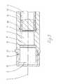
図1には、本発明により提案された第一の実施の形態における注射可能な薬剤を投与する装置の後方領域が示されている。ハウジング1は、溶媒を保持する第一のチャンバ2と、過飽和した塩溶液を保持する第二のチャンバ3と、図1に図示しない、薬剤を保持するアンプルを内部に挿入することのできる薬剤チャンバ4とを収納する。第一のチャンバ2は、ハウジング1の長手方向軸線Dの周りにて同心状に配置された環状チャンバである。第一のチャンバ2は、一端にて閉じられ、閉じた端部に対向する位置にある他端にて第一のチャンバ2は、半透過性膜5により閉じられている。第二のチャンバ3のキャビティは、第一のチャンバ2の外径の全体を亙って第一の領域6内にて伸びており、また、第一の領域6に接続する小径の第二の領域7内にて薬剤チャンバ4内に開放する迄、第一のチャンバ2の環状領域の内部を通って長手方向軸線Dに沿って伸びている。第一の領域6及び第二の領域7は、薄い箔8の形態をした不透過性の分離手段により互いに分離されている。箔8は、大径の領域6の断面表面の全体に亙って伸びており、また、その外側領域が第一のチャンバ2に取り付けられた半透過性膜と対向し且つ、該膜から僅かな距離に位置している。投与装置が非起動状態にあるとき、塩領域は、専ら、第二のチャンバ3の第一の領域6内に配置される。 FIG. 1 shows the rear region of the device for administering an injectable medicament according to the first embodiment proposed by the present invention. The
プランジャ9は、第二のチャンバ3の第二の領域7内にて薬剤を薬剤チャンバ4から送出する送出手段として提供され、該プランジャは、第二の領域7のほぼ全長を亙って伸びている。プランジャ9は、第一の端部にて、その端面が箔8に対向し且つ、箔8から僅かな距離に位置している。プランジャ9は、他端にて、薬剤チャンバ4内に開放し且つ、この端部における端面と組み合わさって駆動面11を構成する。プランジャ9は、長手方向軸線Dに沿って第二のチャンバ領域7内でハウジング1に対して変位し得るように配置され且つ、第二の領域7の形状により案内される。プランジャ9と第二のチャンバ領域7の壁との間に、ゴムリング12の形態をした密封手段が配置されており、該ゴムリングは、投与装置が駆動されたとき、プランジャを第二の領域7及び溶媒から密封する。ゴムリング12はまた、プランジャ9を第二のチャンバ領域7内にて安定化させる作用も果たす。 The plunger 9 is provided as a delivery means for delivering the drug from the
図2には、起動状態にある図1に示した投与装置の実施の形態が示されている。この実施の形態において、浸透圧駆動装置を起動する起動装置は、不透過性箔8と、ハウジング1の長手方向軸線Dに沿って摺動可能なプランジャ9とを備えている。プランジャ9が箔を突き刺す迄、プランジャ9を箔8に向けて薬剤の送出方向と反対方向に動かすことにより、投与装置は起動される。アンプル13を薬剤チャンバ4内に挿入することにより、プランジャ9は箔8に向けた方向に動く。アンプル13が挿入されると、ストッパ14は、プランジャ9の駆動面11を打撃する。ストッパ14と対向する位置に位置するアンプルの出口(図示せず)が最初に閉じられ、プランジャ9は、ストッパ14との接触のため押すことができる。 FIG. 2 shows an embodiment of the administration device shown in FIG. 1 in the activated state. In this embodiment, the activation device that activates the osmotic pressure drive device includes an
不透過性箔8を突き刺したとき、溶媒は、半透過性膜5に到達し、これにより溶液と溶媒との間に浸透圧効果を発生させる。その結果、第二のチャンバ3内で発生された浸透圧力は、プランジャ9をストッパ14に向けた送出方向に長手方向軸線Dに沿って駆動し、その結果、溶液は第二のチャンバ3の第二の領域7に侵入する。アンプルの出口が開放したならば、薬剤は、駆動されたストッパ14によりアンプル13から分与することができる。この場合、アンプル自体は、アダプタによりハウジング内に保持することができる。例えば、アダプタには、突き刺し針が装着されたコネクタ又はルアを設けることができ、該コネクタ又はルアは、出口に接続され且つ、薬剤を所望の箇所に送出する。発生された流量は、膜の材料及び膜の幾何学的形態を選ぶことにより、医療又は治療目的の特定の条件に適応させることができる。溶媒を保持する第一のチャンバ2には、例えば、不織材料のような多孔質材料を充填することが好ましく、この不織材料は、溶媒を毛管力により半透過性膜5まで常に運ぶ。このことは、投与装置がその位置に関係なく作動することを保証する。 When the
逆浸透圧の原理により投与装置を駆動するとき圧力を発生させる浸透圧方法を逆にすることができる。このため、投与装置は再使用可能な設計とすることができる。
図3には、本発明により提案された投与装置の第二の実施の形態を示す部分図が示されている。ハウジング1は、第一のチャンバ2と、第二のチャンバ3と、薬剤チャンバ4とを収納する。ストッパ14を有するアンプル13は、既に、薬剤チャンバ4内に挿入されている。この実施の形態における起動装置は、ハウジング1の長手方向軸線Dに沿ってハウジング1に対し摺動可能なスリーブキャップ15である。該スリーブキャップ15は、ハウジングから密封され且つ、ゴムリング16により該ハウジング上に保持されている。スリーブキャップ15は、投与装置が非起動状態にある、ハウジングに対する第一の位置にてスペーサ17により保持されている。The osmotic method of generating pressure when driving the dosing device according to the principle of reverse osmotic pressure can be reversed. Thus, the administration device can be designed to be reusable.
FIG. 3 is a partial view showing a second embodiment of the administration device proposed by the present invention. The
スリーブキャップ15は、溶媒を保持する第一のチャンバ2の一端と境を画成する。対向する位置にある端部にて、第一のチャンバ2には、不透過性の分離箔8が設けられており、該分離箔は、半透過性膜5と対向する位置にあるチャンバの領域を分離する。不透過性の分離箔8と半透過性膜5との間には隙間距離があり、このため、第一のチャンバ2内の溶媒は、半透過性膜5と接触することはできない。半透過性膜は、第一のチャンバ2に面する端部にて第二のチャンバ3を閉じる。 The
半透過性膜5と対向する端部にて、第二のチャンバ3は、ストッパ14により閉じられている。このため、ストッパ14は、第二のチャンバ3内の過飽和した塩溶液と直接、接触する。投与装置が作動する間、ストッパ14は、薬剤をアンプル13から送出する送出手段として作用する。アンプル13とハウジング1との間のシールはゴムリング18の形態にて提供される。 The
図4には、起動した状態にて図3に示した投与装置が示されている。図3に示したスペーサ17は除去され、スリーブキャップ15は、ハウジングの一端縁を打撃する迄、ハウジングに向けた方向にハウジング1の長手方向軸線Dに沿って押す。このため、スリーブキャップ15は、第二のチャンバ3を圧縮するから、不透過性の箔8に対し圧力を加える。加えられた圧力のため、不透過性の箔8は、破断し、溶媒が半透過性膜5にアクセスすることを自由にする。このことは、アンプル13内でストッパ14に直接、作用する浸透圧過程及び第二のチャンバ3内での浸透圧の蓄積を作動させることになる。ストッパ14は、送出方向に向けて駆動され且つ、薬剤をストッパ14と対向する位置にある出口(図示せず)を通じてアンプル13から押し出す。 FIG. 4 shows the administration device shown in FIG. 3 in the activated state. The spacer 17 shown in FIG. 3 is removed and the
原理上、不透過性の箔8と対向する位置にあるスリーブキャップの内面に鋭角な要素を提供することも可能であり、該鋭角な要素は、箔8の方向に向けてスリーブの内面から突き出し且つ、箔の丁度、手前にて終わっている。スリーブキャップ15がハウジングまで押されたとき、鋭角な要素は、箔8を突き刺し且つ、浸透圧駆動装置を起動し得るように起動過程を助ける。 In principle, it is also possible to provide an acute element on the inner surface of the sleeve cap in a position facing the
1 ハウジング
2 第一のチャンバ
3 第二のチャンバ
4 薬剤チャンバ
5 半透過性膜
6 第一の領域
7 第二の領域
8 箔
9 プランジャ
10 端面
11 駆動面
12 ゴムリング
13 アンプル
14 ストッパ
15 スリーブキャップ
16 ゴムリング
17 スペーサ
18 ゴムリング
D 長手方向軸線DESCRIPTION OF
Claims (16)
Translated fromJapanese溶媒を保持する第一のチャンバ(2)と、
溶液を保持する第二のチャンバ(3)と、
薬剤を保持する薬剤チャンバ(4)とを収納する前記ハウジング(1)と、
b)第一のチャンバ(2)と第二のチャンバ(3)との間に配置された半透過性の膜(5)と、
c)薬剤を薬剤チャンバ(4)から送出する送出手段(9;14)とを備える、注射可能な薬剤を投与する浸透圧駆動装置を備える装置において、
d)不透過性の分離手段(8)を内蔵する浸透圧駆動装置を起動する起動装置(9;15)が、第一のチャンバ(2)と第二のチャンバ(3)との間に設けられ、
e)送出手段(9;14)が、ハウジング(1)の長手方向軸線(D)に沿ってハウジング(1)に対し摺動可能であることを特徴とする、注射可能な薬剤を投与する浸透圧駆動装置を備える装置。a) the housing (1),
A first chamber (2) holding a solvent;
A second chamber (3) holding a solution;
The housing (1) containing a drug chamber (4) for holding a drug;
b) a semi-permeable membrane (5) disposed between the first chamber (2) and the second chamber (3);
c) In an apparatus comprising an osmotic drive for administering an injectable medicament comprising delivery means (9; 14) for delivering the medicament from a medicament chamber (4)
d) An activation device (9; 15) for activating the osmotic pressure drive device incorporating the impermeable separation means (8) is provided between the first chamber (2) and the second chamber (3). And
e) Osmotic delivery of injectable medicament, characterized in that the delivery means (9; 14) are slidable relative to the housing (1) along the longitudinal axis (D) of the housing (1) A device comprising a pressure drive device.
Applications Claiming Priority (2)
| Application Number | Priority Date | Filing Date | Title |
|---|---|---|---|
| DE10233622ADE10233622A1 (en) | 2002-07-24 | 2002-07-24 | Infusion pump, method, control program and semiconductor component for the metered administration of a medical liquid |
| PCT/EP2003/008174WO2004011062A1 (en) | 2002-07-24 | 2003-07-24 | Administration device comprising an osmotic drive |
Publications (1)
| Publication Number | Publication Date |
|---|---|
| JP2005533586Atrue JP2005533586A (en) | 2005-11-10 |
Family
ID=30128332
Family Applications (1)
| Application Number | Title | Priority Date | Filing Date |
|---|---|---|---|
| JP2004523793ACeasedJP2005533586A (en) | 2002-07-24 | 2003-07-24 | Administration device with osmotic pressure drive |
Country Status (9)
| Country | Link |
|---|---|
| US (1) | US7419484B2 (en) |
| EP (3) | EP2484392A1 (en) |
| JP (1) | JP2005533586A (en) |
| AT (2) | ATE555821T1 (en) |
| AU (2) | AU2003238332A1 (en) |
| CA (1) | CA2492836C (en) |
| DE (2) | DE10233622A1 (en) |
| DK (2) | DK1531888T4 (en) |
| WO (2) | WO2004009162A1 (en) |
Cited By (2)
| Publication number | Priority date | Publication date | Assignee | Title |
|---|---|---|---|---|
| JP2008055168A (en)* | 2006-08-30 | 2008-03-13 | Tecpharma Licensing Ag | Dosing device for dosing fluid drug |
| WO2024075724A1 (en)* | 2022-10-07 | 2024-04-11 | テルモ株式会社 | Medicine administration device |
Families Citing this family (14)
| Publication number | Priority date | Publication date | Assignee | Title |
|---|---|---|---|---|
| DE10233622A1 (en) | 2002-07-24 | 2004-02-12 | Disetronic Licensing Ag | Infusion pump, method, control program and semiconductor component for the metered administration of a medical liquid |
| US7226435B2 (en)* | 2004-10-14 | 2007-06-05 | Alcon, Inc. | Drug delivery device |
| US8202267B2 (en) | 2006-10-10 | 2012-06-19 | Medsolve Technologies, Inc. | Method and apparatus for infusing liquid to a body |
| US20080161754A1 (en)* | 2006-12-29 | 2008-07-03 | Medsolve Technologies, Inc. | Method and apparatus for infusing liquid to a body |
| EP2060286B1 (en)* | 2007-11-13 | 2011-01-12 | Acuros GmbH | Osmotic pump |
| US8708961B2 (en) | 2008-01-28 | 2014-04-29 | Medsolve Technologies, Inc. | Apparatus for infusing liquid to a body |
| DK2179755T3 (en) | 2008-10-24 | 2013-06-17 | Hoffmann La Roche | Flexible medicine container with an inner container connection |
| EP2193815B1 (en) | 2008-12-03 | 2013-02-13 | F. Hoffmann-La Roche AG | Flexible container with a preformed fluid channel and infusion pump device using such a container |
| DK2545894T3 (en) | 2009-03-16 | 2018-11-26 | Hoffmann La Roche | Flexible container with insert |
| EP2258333B1 (en) | 2009-06-02 | 2012-08-29 | F.Hoffmann-La Roche Ag | Device for filling a flexible reservoir |
| DK2319477T3 (en) | 2009-11-06 | 2012-04-23 | Hoffmann La Roche | Device for filling a flexible storage container in a vacuum chamber |
| EP2455126B2 (en) | 2010-11-15 | 2023-06-14 | F. Hoffmann-La Roche AG | Container for storing medical or pharmaceutical liquids |
| US11229738B2 (en) | 2016-01-28 | 2022-01-25 | Subcuject Aps | Wearable injection device |
| US10947964B2 (en) | 2017-06-16 | 2021-03-16 | Aav Llc | System and method for precision fluid delivery |
Family Cites Families (41)
| Publication number | Priority date | Publication date | Assignee | Title |
|---|---|---|---|---|
| US2655919A (en)* | 1951-04-17 | 1953-10-20 | Charles B Goodstein | Hypodermic syringe and cartridge therefor |
| US3527216A (en)* | 1969-03-17 | 1970-09-08 | Brockway Glass Co Inc | Hypodermic syringe assembly |
| US3604417A (en)* | 1970-03-31 | 1971-09-14 | Wayne Henry Linkenheimer | Osmotic fluid reservoir for osmotically activated long-term continuous injector device |
| US3760804A (en)* | 1971-01-13 | 1973-09-25 | Alza Corp | Improved osmotic dispenser employing magnesium sulphate and magnesium chloride |
| DE2513467C3 (en)* | 1975-03-26 | 1979-10-31 | Siemens Ag, 1000 Berlin Und 8000 Muenchen | Device for infusing liquids into the human or animal body |
| US4140117A (en)* | 1975-05-12 | 1979-02-20 | Alza Corporation | Cartridge for liquid infusion apparatus |
| US4351335A (en)* | 1979-04-16 | 1982-09-28 | Whitney Douglass G | Injection device and method |
| US4313439A (en)* | 1980-03-24 | 1982-02-02 | Biotek, Inc. | Automated, spring-powered medicament infusion system |
| US4505701A (en)* | 1982-05-17 | 1985-03-19 | Navato Jose R | Automatic parenteral infusion apparatus |
| US4561856A (en)* | 1983-08-18 | 1985-12-31 | Cochran Ulrich D | Infusion pump |
| US4613327A (en)* | 1984-01-26 | 1986-09-23 | Tegrarian Haig V | Apparatus for infusing blood and other related fluids into a patient's body |
| US4513034A (en) | 1984-06-14 | 1985-04-23 | Merck & Co., Inc. | Variable permeability liquid crystalline membranes |
| US4666430A (en)* | 1984-12-05 | 1987-05-19 | I-Flow Corporation | Infusion pump |
| US4639245A (en)* | 1985-12-20 | 1987-01-27 | Oximetrix, Inc. | Fluid infusion pump driver |
| US4838862A (en) | 1986-08-04 | 1989-06-13 | Pharmetrix Corp. | Portable controlled release osmotic infusion device |
| US4773900A (en)* | 1986-08-20 | 1988-09-27 | Cochran Ulrich D | Infusion device |
| US5318539A (en)* | 1986-10-17 | 1994-06-07 | Alexander G. B. O'Neil | Liquid feeding apparatus utilizing capillary tubing, and syringe driver |
| DE19939023A1 (en)* | 1999-08-18 | 2001-02-22 | Disetronic Licensing Ag | Device for administering an injectable product |
| US4997420A (en)† | 1989-12-28 | 1991-03-05 | Lefevre Robert J | Portable drug delivery device including pump with tapered barrel |
| US5169390A (en)* | 1990-05-21 | 1992-12-08 | Athayde Amulya L | Osmotic infusion device |
| SE9002510D0 (en)* | 1990-07-26 | 1990-07-26 | Kabivitrum Ab | APPARATUS FOR CONTROLLED DELIVERY OF LIQUIDS |
| GB9027422D0 (en)* | 1990-12-18 | 1991-02-06 | Scras | Osmotically driven infusion device |
| WO1994005354A1 (en)* | 1992-09-09 | 1994-03-17 | Alza Corporation | Fluid driven dispensing device |
| US5957672A (en)* | 1993-11-10 | 1999-09-28 | The United States Of America As Represented By The Administrator Of The National Aeronautics And Space Administration | Blood pump bearing system |
| FR2724321A1 (en)* | 1994-09-14 | 1996-03-15 | Hospal Ind | DEVICE FOR MEASURING THE PRESSURE OF A LIQUID AND METHOD FOR ADJUSTING SUCH A DEVICE |
| US5743879A (en)† | 1994-12-02 | 1998-04-28 | Science Incorporated | Medicament dispenser |
| JPH09262285A (en)† | 1996-03-28 | 1997-10-07 | Terumo Corp | Infusion device and bag for liquid medicine |
| US5869078A (en) | 1996-04-25 | 1999-02-09 | Medtronic Inc. | Implantable variable permeability drug infusion techniques |
| DE19647701A1 (en)* | 1996-11-08 | 1998-05-14 | Schering Ag | Device for obtaining constant densities of contrast media in tissues and organs |
| MY125849A (en)* | 1997-07-25 | 2006-08-30 | Alza Corp | Osmotic delivery system, osmotic delivery system semipermeable body assembly, and method for controlling delivery rate of beneficial agents from osmotic delivery systems |
| US6348043B1 (en)* | 1998-12-29 | 2002-02-19 | Mckinley Medical, Lllp | Multi-dose infusion pump providing minimal flow between doses |
| US6645177B1 (en)† | 1999-02-09 | 2003-11-11 | Alaris Medical Systems, Inc. | Directly engaged syringe driver system |
| US6666665B1 (en)* | 1999-03-04 | 2003-12-23 | Baxter International Inc. | Fluid delivery mechanism having a plurality of plungers for compressing a metering chamber |
| DE19916876A1 (en)* | 1999-04-14 | 2000-11-02 | Clemens Micheler | Medical dosing pump |
| US6471675B1 (en)* | 1999-04-30 | 2002-10-29 | Medtronic, Inc. | Passive flow control devices for implantable pumps |
| DE19947826B4 (en)* | 1999-10-05 | 2006-06-08 | Disetronic Licensing Ag | Device for the metered administration of an injectable product |
| GB9924072D0 (en)* | 1999-10-12 | 1999-12-15 | Royal Wolverhampton Hospitals | Continuous infusion apparatus |
| DE19955368A1 (en)* | 1999-11-17 | 2001-05-23 | Lre Technology Partner Gmbh | Infusion delivery apparatus, comprises a container and holder, a drop chamber, a throttling valve, and a weight measurement unit |
| US6689101B2 (en)* | 2000-05-22 | 2004-02-10 | Pharmacia Ab | Medical arrangement |
| US6752781B2 (en)* | 2001-06-08 | 2004-06-22 | Sergio Landau | Durable hypodermic jet injector apparatus and method |
| DE10233622A1 (en) | 2002-07-24 | 2004-02-12 | Disetronic Licensing Ag | Infusion pump, method, control program and semiconductor component for the metered administration of a medical liquid |
- 2002
- 2002-07-24DEDE10233622Apatent/DE10233622A1/ennot_activeWithdrawn
- 2003
- 2003-07-08DKDK03732167.6Tpatent/DK1531888T4/enactive
- 2003-07-08ATAT03732167Tpatent/ATE555821T1/enactive
- 2003-07-08EPEP12166241Apatent/EP2484392A1/ennot_activeCeased
- 2003-07-08AUAU2003238332Apatent/AU2003238332A1/ennot_activeAbandoned
- 2003-07-08EPEP03732167.6Apatent/EP1531888B2/ennot_activeExpired - Lifetime
- 2003-07-08WOPCT/CH2003/000456patent/WO2004009162A1/ennot_activeApplication Discontinuation
- 2003-07-24WOPCT/EP2003/008174patent/WO2004011062A1/enactiveIP Right Grant
- 2003-07-24DKDK03771096Tpatent/DK1523354T3/enactive
- 2003-07-24DEDE50310438Tpatent/DE50310438D1/denot_activeExpired - Fee Related
- 2003-07-24EPEP03771096Apatent/EP1523354B1/ennot_activeExpired - Lifetime
- 2003-07-24CACA002492836Apatent/CA2492836C/ennot_activeExpired - Fee Related
- 2003-07-24AUAU2003250170Apatent/AU2003250170A1/ennot_activeAbandoned
- 2003-07-24JPJP2004523793Apatent/JP2005533586A/ennot_activeCeased
- 2003-07-24ATAT03771096Tpatent/ATE406927T1/ennot_activeIP Right Cessation
- 2005
- 2005-01-24USUS11/041,913patent/US7419484B2/ennot_activeExpired - Fee Related
Cited By (2)
| Publication number | Priority date | Publication date | Assignee | Title |
|---|---|---|---|---|
| JP2008055168A (en)* | 2006-08-30 | 2008-03-13 | Tecpharma Licensing Ag | Dosing device for dosing fluid drug |
| WO2024075724A1 (en)* | 2022-10-07 | 2024-04-11 | テルモ株式会社 | Medicine administration device |
Also Published As
| Publication number | Publication date |
|---|---|
| EP1523354B1 (en) | 2008-09-03 |
| EP2484392A1 (en) | 2012-08-08 |
| DK1523354T3 (en) | 2008-12-15 |
| EP1531888B2 (en) | 2016-03-23 |
| AU2003250170A1 (en) | 2004-02-16 |
| DK1531888T4 (en) | 2016-07-04 |
| DE10233622A1 (en) | 2004-02-12 |
| US7419484B2 (en) | 2008-09-02 |
| DE50310438D1 (en) | 2008-10-16 |
| CA2492836A1 (en) | 2004-02-05 |
| EP1531888B1 (en) | 2012-05-02 |
| EP1523354A1 (en) | 2005-04-20 |
| WO2004009162A1 (en) | 2004-01-29 |
| AU2003238332A1 (en) | 2004-02-09 |
| ATE406927T1 (en) | 2008-09-15 |
| DK1531888T3 (en) | 2012-08-13 |
| EP1531888A1 (en) | 2005-05-25 |
| CA2492836C (en) | 2008-02-19 |
| US20050182391A1 (en) | 2005-08-18 |
| ATE555821T1 (en) | 2012-05-15 |
| WO2004011062A1 (en) | 2004-02-05 |
Similar Documents
| Publication | Publication Date | Title |
|---|---|---|
| JP7053709B2 (en) | Vial transfer and injection equipment and methods | |
| US11839738B2 (en) | Medication infusion device | |
| AU2017203997B2 (en) | Insertion mechanisms having vented fluid pathways for drug delivery pumps | |
| FI107434B (en) | Osmotpumpar | |
| JP2005533586A (en) | Administration device with osmotic pressure drive | |
| JP4660589B2 (en) | Administration device for administering a fluid formulation | |
| US8684968B2 (en) | Hypodermic drug delivery reservoir and apparatus | |
| US10617820B2 (en) | Fluid restriction mechanisms for drug delivery pumps | |
| EP2398534B1 (en) | Drug container with delivery mechanism and with a first sealing element | |
| JP2009537184A (en) | Device for dispensing fluid products | |
| CN103025370A (en) | Fluid delivery device needle retraction mechanism, barrel and expandable hydraulic fluid seal | |
| CN113874056B (en) | Cartridge Adapters for Drug Delivery Devices | |
| CN116075329A (en) | Valve assembly for drug delivery device | |
| US20180369552A1 (en) | Device and method | |
| GB2547896A (en) | Closure member with septum |
Legal Events
| Date | Code | Title | Description |
|---|---|---|---|
| A131 | Notification of reasons for refusal | Free format text:JAPANESE INTERMEDIATE CODE: A131 Effective date:20080424 | |
| A601 | Written request for extension of time | Free format text:JAPANESE INTERMEDIATE CODE: A601 Effective date:20080724 | |
| A602 | Written permission of extension of time | Free format text:JAPANESE INTERMEDIATE CODE: A602 Effective date:20080731 | |
| A521 | Request for written amendment filed | Free format text:JAPANESE INTERMEDIATE CODE: A523 Effective date:20080807 | |
| A01 | Written decision to grant a patent or to grant a registration (utility model) | Free format text:JAPANESE INTERMEDIATE CODE: A01 Effective date:20081001 | |
| A045 | Written measure of dismissal of application [lapsed due to lack of payment] | Free format text:JAPANESE INTERMEDIATE CODE: A045 Effective date:20090219 |