JP2005530550A - Implantable prosthesis - Google Patents
Implantable prosthesisDownload PDFInfo
- Publication number
- JP2005530550A JP2005530550AJP2004515682AJP2004515682AJP2005530550AJP 2005530550 AJP2005530550 AJP 2005530550AJP 2004515682 AJP2004515682 AJP 2004515682AJP 2004515682 AJP2004515682 AJP 2004515682AJP 2005530550 AJP2005530550 AJP 2005530550A
- Authority
- JP
- Japan
- Prior art keywords
- graft
- sheath
- stent
- peelable
- catheter
- Prior art date
- Legal status (The legal status is an assumption and is not a legal conclusion. Google has not performed a legal analysis and makes no representation as to the accuracy of the status listed.)
- Granted
Links
- 238000000034methodMethods0.000claimsabstractdescription30
- 210000004204blood vesselAnatomy0.000claimsabstractdescription21
- 208000007474aortic aneurysmDiseases0.000claimsabstractdescription11
- 210000003090iliac arteryAnatomy0.000claimsdescription17
- 210000000709aortaAnatomy0.000claimsdescription15
- 238000003780insertionMethods0.000claimsdescription15
- 230000037431insertionEffects0.000claimsdescription15
- 208000002223abdominal aortic aneurysmDiseases0.000claimsdescription2
- 206010002329AneurysmDiseases0.000abstractdescription9
- 238000004873anchoringMethods0.000abstract1
- 239000000463materialSubstances0.000description7
- 229920003023plasticPolymers0.000description5
- 239000004033plasticSubstances0.000description5
- 239000004372Polyvinyl alcoholSubstances0.000description2
- 230000017531blood circulationEffects0.000description2
- 230000036760body temperatureEffects0.000description2
- 238000012986modificationMethods0.000description2
- 230000004048modificationEffects0.000description2
- 229920002451polyvinyl alcoholPolymers0.000description2
- 206010003210ArteriosclerosisDiseases0.000description1
- 230000009471actionEffects0.000description1
- 238000004026adhesive bondingMethods0.000description1
- 208000011775arteriosclerosis diseaseDiseases0.000description1
- 230000008859changeEffects0.000description1
- 230000001010compromised effectEffects0.000description1
- 230000002950deficientEffects0.000description1
- 238000013461designMethods0.000description1
- 238000010586diagramMethods0.000description1
- 230000010339dilationEffects0.000description1
- 229920000295expanded polytetrafluoroethylenePolymers0.000description1
- 210000001621ilium boneAnatomy0.000description1
- 238000003384imaging methodMethods0.000description1
- 238000002513implantationMethods0.000description1
- 230000007246mechanismEffects0.000description1
- 230000005012migrationEffects0.000description1
- 238000013508migrationMethods0.000description1
- 229920000728polyesterPolymers0.000description1
- 229920001296polysiloxanePolymers0.000description1
- 210000002254renal arteryAnatomy0.000description1
- 230000008439repair processEffects0.000description1
- 238000004904shorteningMethods0.000description1
- 239000007787solidSubstances0.000description1
- 230000002123temporal effectEffects0.000description1
- 238000007794visualization techniqueMethods0.000description1
- 238000010792warmingMethods0.000description1
Images


Classifications
- A—HUMAN NECESSITIES
- A61—MEDICAL OR VETERINARY SCIENCE; HYGIENE
- A61F—FILTERS IMPLANTABLE INTO BLOOD VESSELS; PROSTHESES; DEVICES PROVIDING PATENCY TO, OR PREVENTING COLLAPSING OF, TUBULAR STRUCTURES OF THE BODY, e.g. STENTS; ORTHOPAEDIC, NURSING OR CONTRACEPTIVE DEVICES; FOMENTATION; TREATMENT OR PROTECTION OF EYES OR EARS; BANDAGES, DRESSINGS OR ABSORBENT PADS; FIRST-AID KITS
- A61F2/00—Filters implantable into blood vessels; Prostheses, i.e. artificial substitutes or replacements for parts of the body; Appliances for connecting them with the body; Devices providing patency to, or preventing collapsing of, tubular structures of the body, e.g. stents
- A61F2/02—Prostheses implantable into the body
- A61F2/04—Hollow or tubular parts of organs, e.g. bladders, tracheae, bronchi or bile ducts
- A61F2/06—Blood vessels
- A61F2/07—Stent-grafts
- A—HUMAN NECESSITIES
- A61—MEDICAL OR VETERINARY SCIENCE; HYGIENE
- A61F—FILTERS IMPLANTABLE INTO BLOOD VESSELS; PROSTHESES; DEVICES PROVIDING PATENCY TO, OR PREVENTING COLLAPSING OF, TUBULAR STRUCTURES OF THE BODY, e.g. STENTS; ORTHOPAEDIC, NURSING OR CONTRACEPTIVE DEVICES; FOMENTATION; TREATMENT OR PROTECTION OF EYES OR EARS; BANDAGES, DRESSINGS OR ABSORBENT PADS; FIRST-AID KITS
- A61F2/00—Filters implantable into blood vessels; Prostheses, i.e. artificial substitutes or replacements for parts of the body; Appliances for connecting them with the body; Devices providing patency to, or preventing collapsing of, tubular structures of the body, e.g. stents
- A61F2/95—Instruments specially adapted for placement or removal of stents or stent-grafts
- A61F2/954—Instruments specially adapted for placement or removal of stents or stent-grafts for placing stents or stent-grafts in a bifurcation
- A—HUMAN NECESSITIES
- A61—MEDICAL OR VETERINARY SCIENCE; HYGIENE
- A61F—FILTERS IMPLANTABLE INTO BLOOD VESSELS; PROSTHESES; DEVICES PROVIDING PATENCY TO, OR PREVENTING COLLAPSING OF, TUBULAR STRUCTURES OF THE BODY, e.g. STENTS; ORTHOPAEDIC, NURSING OR CONTRACEPTIVE DEVICES; FOMENTATION; TREATMENT OR PROTECTION OF EYES OR EARS; BANDAGES, DRESSINGS OR ABSORBENT PADS; FIRST-AID KITS
- A61F2/00—Filters implantable into blood vessels; Prostheses, i.e. artificial substitutes or replacements for parts of the body; Appliances for connecting them with the body; Devices providing patency to, or preventing collapsing of, tubular structures of the body, e.g. stents
- A61F2/95—Instruments specially adapted for placement or removal of stents or stent-grafts
- A61F2/958—Inflatable balloons for placing stents or stent-grafts
- A—HUMAN NECESSITIES
- A61—MEDICAL OR VETERINARY SCIENCE; HYGIENE
- A61F—FILTERS IMPLANTABLE INTO BLOOD VESSELS; PROSTHESES; DEVICES PROVIDING PATENCY TO, OR PREVENTING COLLAPSING OF, TUBULAR STRUCTURES OF THE BODY, e.g. STENTS; ORTHOPAEDIC, NURSING OR CONTRACEPTIVE DEVICES; FOMENTATION; TREATMENT OR PROTECTION OF EYES OR EARS; BANDAGES, DRESSINGS OR ABSORBENT PADS; FIRST-AID KITS
- A61F2/00—Filters implantable into blood vessels; Prostheses, i.e. artificial substitutes or replacements for parts of the body; Appliances for connecting them with the body; Devices providing patency to, or preventing collapsing of, tubular structures of the body, e.g. stents
- A61F2/82—Devices providing patency to, or preventing collapsing of, tubular structures of the body, e.g. stents
- A61F2/86—Stents in a form characterised by the wire-like elements; Stents in the form characterised by a net-like or mesh-like structure
- A61F2/88—Stents in a form characterised by the wire-like elements; Stents in the form characterised by a net-like or mesh-like structure the wire-like elements formed as helical or spiral coils
- A—HUMAN NECESSITIES
- A61—MEDICAL OR VETERINARY SCIENCE; HYGIENE
- A61F—FILTERS IMPLANTABLE INTO BLOOD VESSELS; PROSTHESES; DEVICES PROVIDING PATENCY TO, OR PREVENTING COLLAPSING OF, TUBULAR STRUCTURES OF THE BODY, e.g. STENTS; ORTHOPAEDIC, NURSING OR CONTRACEPTIVE DEVICES; FOMENTATION; TREATMENT OR PROTECTION OF EYES OR EARS; BANDAGES, DRESSINGS OR ABSORBENT PADS; FIRST-AID KITS
- A61F2/00—Filters implantable into blood vessels; Prostheses, i.e. artificial substitutes or replacements for parts of the body; Appliances for connecting them with the body; Devices providing patency to, or preventing collapsing of, tubular structures of the body, e.g. stents
- A61F2/82—Devices providing patency to, or preventing collapsing of, tubular structures of the body, e.g. stents
- A61F2/86—Stents in a form characterised by the wire-like elements; Stents in the form characterised by a net-like or mesh-like structure
- A61F2/89—Stents in a form characterised by the wire-like elements; Stents in the form characterised by a net-like or mesh-like structure the wire-like elements comprising two or more adjacent rings flexibly connected by separate members
- A—HUMAN NECESSITIES
- A61—MEDICAL OR VETERINARY SCIENCE; HYGIENE
- A61F—FILTERS IMPLANTABLE INTO BLOOD VESSELS; PROSTHESES; DEVICES PROVIDING PATENCY TO, OR PREVENTING COLLAPSING OF, TUBULAR STRUCTURES OF THE BODY, e.g. STENTS; ORTHOPAEDIC, NURSING OR CONTRACEPTIVE DEVICES; FOMENTATION; TREATMENT OR PROTECTION OF EYES OR EARS; BANDAGES, DRESSINGS OR ABSORBENT PADS; FIRST-AID KITS
- A61F2/00—Filters implantable into blood vessels; Prostheses, i.e. artificial substitutes or replacements for parts of the body; Appliances for connecting them with the body; Devices providing patency to, or preventing collapsing of, tubular structures of the body, e.g. stents
- A61F2/02—Prostheses implantable into the body
- A61F2/04—Hollow or tubular parts of organs, e.g. bladders, tracheae, bronchi or bile ducts
- A61F2/06—Blood vessels
- A61F2002/065—Y-shaped blood vessels
- A—HUMAN NECESSITIES
- A61—MEDICAL OR VETERINARY SCIENCE; HYGIENE
- A61F—FILTERS IMPLANTABLE INTO BLOOD VESSELS; PROSTHESES; DEVICES PROVIDING PATENCY TO, OR PREVENTING COLLAPSING OF, TUBULAR STRUCTURES OF THE BODY, e.g. STENTS; ORTHOPAEDIC, NURSING OR CONTRACEPTIVE DEVICES; FOMENTATION; TREATMENT OR PROTECTION OF EYES OR EARS; BANDAGES, DRESSINGS OR ABSORBENT PADS; FIRST-AID KITS
- A61F2/00—Filters implantable into blood vessels; Prostheses, i.e. artificial substitutes or replacements for parts of the body; Appliances for connecting them with the body; Devices providing patency to, or preventing collapsing of, tubular structures of the body, e.g. stents
- A61F2/02—Prostheses implantable into the body
- A61F2/04—Hollow or tubular parts of organs, e.g. bladders, tracheae, bronchi or bile ducts
- A61F2/06—Blood vessels
- A61F2/07—Stent-grafts
- A61F2002/075—Stent-grafts the stent being loosely attached to the graft material, e.g. by stitching
- A—HUMAN NECESSITIES
- A61—MEDICAL OR VETERINARY SCIENCE; HYGIENE
- A61F—FILTERS IMPLANTABLE INTO BLOOD VESSELS; PROSTHESES; DEVICES PROVIDING PATENCY TO, OR PREVENTING COLLAPSING OF, TUBULAR STRUCTURES OF THE BODY, e.g. STENTS; ORTHOPAEDIC, NURSING OR CONTRACEPTIVE DEVICES; FOMENTATION; TREATMENT OR PROTECTION OF EYES OR EARS; BANDAGES, DRESSINGS OR ABSORBENT PADS; FIRST-AID KITS
- A61F2/00—Filters implantable into blood vessels; Prostheses, i.e. artificial substitutes or replacements for parts of the body; Appliances for connecting them with the body; Devices providing patency to, or preventing collapsing of, tubular structures of the body, e.g. stents
- A61F2/95—Instruments specially adapted for placement or removal of stents or stent-grafts
- A61F2002/9505—Instruments specially adapted for placement or removal of stents or stent-grafts having retaining means other than an outer sleeve, e.g. male-female connector between stent and instrument
- A61F2002/9511—Instruments specially adapted for placement or removal of stents or stent-grafts having retaining means other than an outer sleeve, e.g. male-female connector between stent and instrument the retaining means being filaments or wires
- A—HUMAN NECESSITIES
- A61—MEDICAL OR VETERINARY SCIENCE; HYGIENE
- A61F—FILTERS IMPLANTABLE INTO BLOOD VESSELS; PROSTHESES; DEVICES PROVIDING PATENCY TO, OR PREVENTING COLLAPSING OF, TUBULAR STRUCTURES OF THE BODY, e.g. STENTS; ORTHOPAEDIC, NURSING OR CONTRACEPTIVE DEVICES; FOMENTATION; TREATMENT OR PROTECTION OF EYES OR EARS; BANDAGES, DRESSINGS OR ABSORBENT PADS; FIRST-AID KITS
- A61F2/00—Filters implantable into blood vessels; Prostheses, i.e. artificial substitutes or replacements for parts of the body; Appliances for connecting them with the body; Devices providing patency to, or preventing collapsing of, tubular structures of the body, e.g. stents
- A61F2/95—Instruments specially adapted for placement or removal of stents or stent-grafts
- A61F2/958—Inflatable balloons for placing stents or stent-grafts
- A61F2002/9583—Means for holding the stent on the balloon, e.g. using protrusions, adhesives or an outer sleeve
- Y—GENERAL TAGGING OF NEW TECHNOLOGICAL DEVELOPMENTS; GENERAL TAGGING OF CROSS-SECTIONAL TECHNOLOGIES SPANNING OVER SEVERAL SECTIONS OF THE IPC; TECHNICAL SUBJECTS COVERED BY FORMER USPC CROSS-REFERENCE ART COLLECTIONS [XRACs] AND DIGESTS
- Y10—TECHNICAL SUBJECTS COVERED BY FORMER USPC
- Y10S—TECHNICAL SUBJECTS COVERED BY FORMER USPC CROSS-REFERENCE ART COLLECTIONS [XRACs] AND DIGESTS
- Y10S623/00—Prosthesis, i.e. artificial body members, parts thereof, or aids and accessories therefor
- Y10S623/902—Method of implanting
- Y10S623/903—Blood vessel
Landscapes
- Health & Medical Sciences (AREA)
- Engineering & Computer Science (AREA)
- Biomedical Technology (AREA)
- Heart & Thoracic Surgery (AREA)
- Public Health (AREA)
- Transplantation (AREA)
- Cardiology (AREA)
- Veterinary Medicine (AREA)
- Oral & Maxillofacial Surgery (AREA)
- Vascular Medicine (AREA)
- Life Sciences & Earth Sciences (AREA)
- Animal Behavior & Ethology (AREA)
- General Health & Medical Sciences (AREA)
- Gastroenterology & Hepatology (AREA)
- Pulmonology (AREA)
- Prostheses (AREA)
- Media Introduction/Drainage Providing Device (AREA)
- Materials For Medical Uses (AREA)
Abstract
Translated fromJapaneseDescription
Translated fromJapanese本発明は一般に、管腔内内挿的に(endoluminally)移植可能な(implantable)管腔プロテーゼ(luminal prostheses)に関する。さらに具体的には、硬質な外側シース(solid outer sheath)を用いずに留置される、人体管腔内部、特に血管内部に移植可能なプロテーゼに関する。 The present invention generally relates to endoluminally implantable luminal prostheses. More specifically, the present invention relates to a prosthesis that can be implanted inside a human body lumen, particularly inside a blood vessel, which is placed without using a solid outer sheath.
周知のプロテーゼは、肥大部の修復や、損傷した人体管腔(例えば、血管)の治療に用いられる。これらプロテーゼは一般に、管状のグラフトを有する。管状のグラフトは、編まれた(woven)、または、成形された(molded)高分子材料を有し、場合により、内部または外部に配された機械式支持構造体により全体的に、または、部分的に、支持される。この構造体は、通例、ステントと呼ばれる。上記の目的で使用されるプロテーゼは、プロテーゼを必要としている人体管腔内の場所からは離れているが管腔により通じているアクセス位置から経皮的に入れられる。このため、プロテーゼは圧縮されて、その圧縮された状態で保持され、管腔内を経て治療を要する場所まで移動され、その場で膨張されて固定される。その膨張は、例えばバルーン・カテーテルを用いて機械的な作用で行われてよく、または、弾性力もしくは相変化による力の作用の下で自動的に行われてもよい。 Known prostheses are used to repair enlarged areas and to treat damaged body lumens (eg, blood vessels). These prostheses generally have a tubular graft. Tubular grafts have a woven or molded polymeric material, optionally in whole or in part by a mechanical support structure arranged inside or outside. Supported. This structure is commonly referred to as a stent. The prosthesis used for the above purpose is placed percutaneously from an access location that is remote from the location in the body lumen where the prosthesis is needed but is communicated by the lumen. For this reason, the prosthesis is compressed, held in its compressed state, moved through the lumen to a place where treatment is required, and inflated and fixed in place. The inflation may be performed mechanically, for example using a balloon catheter, or may be performed automatically under the action of elastic force or force due to phase change.
プロテーゼは一般に、その第1の構成を、送達カテーテル(delivery catheter)内に保持されるか、または、送達カテーテルの前方先端部そのものである外側スリーブまたはシース(outer sleeve or sheath)内において保持される。このような送達カテーテルは、アクセス位置から導入され、巧みに操られて管腔系を通ってプロテーゼを必要とする場所へ送られる。プロテーゼがその位置に到達すると、送達カテーテルから出されるか、または、所定の場所に保持され、その間に送達用、および、その他の周囲を取り囲むスリーブの少なくともいずれかが撤収される。 A prosthesis is generally held in its first configuration within a delivery catheter or within an outer sleeve or sheath that is itself the front tip of the delivery catheter. . Such delivery catheters are introduced from the access location and are manipulated and sent through the luminal system to the place where the prosthesis is needed. When the prosthesis reaches its position, it is either removed from the delivery catheter or held in place while the delivery and / or other surrounding sleeves are withdrawn.
別の方法では、プロテーゼを圧縮してその断面を減縮し、圧縮した状態でプロテーゼを、既に患者内に挿入されているカテーテル内へ押し出すステップを有する。プッシャーを用い、圧縮されたエンドプロテーゼ(endoprosthesis)をカテーテルに通してその遠位端を出し、所定の場所において膨張させる。この方法の欠点の1つに、デバイスは、相当な力を受けてカテーテルから押し出され、管腔との摩擦を乗り越えなければならない点が挙げられる。上記いずれの場合においても、プロテーゼ、および、プロテーゼを留置(配置)位置まで送達する、周囲を取り囲んでいるカテーテルの断面部は、このようなシステムの使用および留置の困難性に影響を与える因子の1つである。 Another method includes compressing the prosthesis to reduce its cross-section and, in the compressed state, pushing the prosthesis into a catheter that has already been inserted into the patient. Using a pusher, a compressed endoprosthesis is passed through the catheter to exit its distal end and inflated in place. One disadvantage of this method is that the device must be pushed out of the catheter under considerable force to overcome the friction with the lumen. In any of the above cases, the cross-section of the surrounding catheter that delivers the prosthesis and the prosthesis to the indwelling (deployment) position is a factor that affects the use and difficulty of such a system. One.
このようなプロテーゼを用いる格別な用途の1つに、腹部大動脈瘤の治療がある。このような動脈瘤は、通例、動脈硬化症に罹っている大動脈の腎臓下部(infrarenal portion)、腎動脈と2つの腸骨動脈の間や、場合によっては大動脈の分岐部を越えて一方または両方の腸骨動脈に渡って発症する。この領域を治療するための一般的なプロテーゼは、分岐した管状のグラフトもしくはステント・グラフトを備え、これらは、大動脈セクション(通例、動脈瘤内に留置されることになるプロテーゼのセクション)、および、大動脈セクションから腸骨動脈へ延びる2つの腸骨動脈セクションを有する。分岐したグラフト・プロテーゼを、経管腔内内挿的に一方の腸骨動脈に挿入し、プロテーゼの一部分であるステントを膨張させて大動脈に固定するステップを有する方法が知られている。 One particular application using such prostheses is in the treatment of abdominal aortic aneurysms. Such aneurysms are usually one or both of the infrarenal portion of the aorta suffering from arteriosclerosis, between the renal arteries and the two iliac arteries and possibly beyond the bifurcation of the aorta It affects the iliac arteries. A typical prosthesis for treating this area comprises a bifurcated tubular graft or stent graft, which is an aortic section (typically the section of the prosthesis that will be placed in the aneurysm), and It has two iliac artery sections extending from the aorta section to the iliac artery. Methods are known that include the step of inserting a bifurcated graft prosthesis intraluminally into one iliac artery and expanding and securing a stent that is part of the prosthesis to the aorta.
また、自己膨張性の管状ステント−グラフトを圧縮し、編んだ可剥性シースによって自己膨張の力に抗し、膨張した状態との比較において減縮された断面を有する構成に拘束することも知られている。シースに収められたプロテーゼを体内の所定の場所に挿入した後、シースのフィラメントを末端方向に引っ張ってシースの編みを解いて(de-knit)シースを1本のフィラメントの糸としてプロテーゼから取り去れるようにし、プロテーゼを使用形態に相応した断面まで膨張できるようにする。プロテーゼの全長に延在した鎖編みされた部材(crocheted material)の網(meshworks)を有するシースが知られている。しかしながら、一旦、引き紐(drawstring)を引けば支持用ステント(supporting stent)の膨張によりプロテーゼの位置を周囲の管腔に対してそれ以上調整することが困難となる点は、このような構成の有する欠点の1つである。 It is also known to compress a self-expanding tubular stent-graft and resist a self-expanding force with a knitted peelable sheath and constrain it to a configuration having a reduced cross-section compared to the expanded state. ing. After the prosthesis contained in the sheath is inserted into the body in place, the sheath filament is pulled distally to de-knit the sheath, and the sheath is removed from the prosthesis as a single filament thread. The prosthesis can be expanded to a cross-section corresponding to the use form. Sheaths are known which have a meshwork of crocheted material extending the entire length of the prosthesis. However, once the drawstring is pulled, it becomes difficult to further adjust the position of the prosthesis relative to the surrounding lumen due to the expansion of the supporting stent. This is one of the disadvantages.
本発明は、治療を要する人体管腔に、経管腔内内挿的に送達される(intraluminal delivery)グラフトシステムを有する。本システムは、グラフト、グラフトを半径方向に膨張させる手段、および、グラフトの少なくとも一端を治療の必要がある管腔に固定する手段(これら手段には、場合によってはグラフトの少なくとも一部に配されたバルーン膨張性の有刺ステントが含まれる。)、ならびに、グラフトの少なくとも一部の周囲に可剥性シースを有する。可剥性シースは、取り外し可能であり、プロテーゼを圧縮された状態に保持するための硬い外側シースの必要性を排除している。用いられる可剥性シースの種類によっては、引き紐を引っ張ってシースを解いて、つまり、ほどいて、取り除くことができる。ある実施形態においては、切り込み線を有する(scored)プラスチック製シースが用いられており、切り込み線の入ったプラスチックによる包囲は、シースの切り込み線で分割を行って解かれる。好ましい実施形態では、縛られた鎖編み状のシース(tied crocheted sheath)が用いられる。このシースは、シース全体を解いてグラフトの膨張を可能にする引き紐を引っ張ることで取り除かれる。 The present invention has a graft system for intraluminal delivery into a human lumen requiring treatment. The system includes a graft, means for radially expanding the graft, and means for securing at least one end of the graft to a lumen in need of treatment (these means are optionally disposed on at least a portion of the graft). A balloon expandable barbed stent), and a peelable sheath around at least a portion of the graft. The peelable sheath is removable, eliminating the need for a rigid outer sheath to hold the prosthesis in a compressed state. Depending on the type of peelable sheath used, it can be removed by pulling on the pull string to unwind, ie, unwind. In some embodiments, a plastic sheath having a scored line is used, and the encircling of the scored plastic is unraveled by splitting at the scored line of the sheath. In a preferred embodiment, a tied crocheted sheath is used. The sheath is removed by pulling on a drawstring that unwinds the entire sheath and allows the graft to expand.
本発明の好ましい実施形態は、大動脈瘤に経管腔内内挿的に送達される二股状グラフトシステムを有する。このシステムは、大動脈セクションおよび2つの腸骨動脈脚部を備えた二股状グラフト、大動脈セクションの端部近傍に配される可膨張性ステント、ならびに、大動脈セクションおよび2つの脚部の一方に周設された可剥性鎖編み状シースを有する。動脈瘤内における初期的留置の後、可剥性鎖網状シースは、シースを解くことで除去可能で、もってグラフトの膨張を可能にする。 A preferred embodiment of the present invention has a bifurcated graft system that is delivered transluminally into an aortic aneurysm. The system includes a bifurcated graft with an aortic section and two iliac arterial legs, an inflatable stent disposed near the end of the aortic section, and a circumference of one of the aortic section and the two legs. A peelable chain braided sheath. After initial placement within the aneurysm, the peelable chain reticulated sheath can be removed by unwinding the sheath, thus allowing the graft to expand.
また、本発明は、グラフトシステムを挿入して治療を要する血管(vessel)を治療する方法を含んでいる。本方法は、カテーテルを人体管腔のアクセス位置から治療を必要とする場所まで挿入するステップを有する。本カテーテルは、軸方向に留置されたプッシュ・ロッド(push rod)の前方端部に本発明に係るグラフトシステムを備え、そのグラフト自体は、硬いシース外装を備えていない。留置位置にまで送達されると、(好ましい実施形態においては)引き紐が引かれ、可剥性鎖編み状シースがほどかれてグラフトの膨張が可能になる。次に、グラフトの位置決めが行われる。位置決めは、放射線不透過性マーカおよび画像化システムといった手段で行われ、そしてグラフトは、例えば、端部にとげを備えたバルーン膨張性ステントによって膨張される。このようにして、グラフトは、血管内部に固定される。そしてカテーテルは、取り除かれる。 The present invention also includes a method of treating a vessel that requires treatment by inserting a graft system. The method includes the step of inserting a catheter from an access location in a human body lumen to a location requiring treatment. The catheter is equipped with a graft system according to the present invention at the forward end of an axially placed push rod, which itself does not have a hard sheath sheath. When delivered to the indwelling position, the drawstring is pulled (in a preferred embodiment), and the peelable braided sheath is unwound allowing the graft to expand. Next, the positioning of the graft is performed. Positioning is performed by means such as radiopaque markers and an imaging system, and the graft is inflated, for example, by a balloon expandable stent with barbs at the ends. In this way, the graft is fixed inside the blood vessel. The catheter is then removed.
新規と思われる本発明の特徴、および、本発明の要素の特性について、付随する特許請求の範囲の特徴と併せて説明する。図面は、単なる例示目的で示され、一定のスケールで描いていない。とはいえ、機構および運用方法の両方について、添付の図面と併せて以下に記す詳細な説明を参照することにより、本発明自体への理解もさらに深まると思われる。 The features of the invention believed to be novel and the characteristics of the elements of the invention are described in conjunction with the features of the appended claims. The drawings are shown for illustrative purposes only and are not drawn to scale. Nevertheless, the understanding of the invention itself will be further enhanced by reference to the detailed description set forth below, both in terms of mechanism and method of operation, in conjunction with the accompanying drawings.
本発明は、グラフトシステム、および、それを用いて病んだもしくはその他不具合のある人体管腔を治療する方法を含む。本発明の好ましい実施形態は、治療を要する血管内に経管腔内内挿的送達(intraluminal delivery)を行うためのグラフトシステムを有する。このグラフトシステムは、グラフトと、グラフトを膨張させて完全に膨張した構成にするための半径方向膨張手段(好ましくは、グラフトの少なくとも部分内部に配されたバルーン膨張性ステント)と、グラフトの少なくとも部分に周設された可剥性鎖編み状シースとを有する。可剥性鎖編み状シースは、取り除いてグラフトおよびステントの膨張を可能にすることができる。治療を要する大動脈瘤内に経管腔内内挿的に送達するための二股状グラフトシステムは、本発明の一部に含まれる。本システムは、末端領域(遠位領域)および2つの脚部を有する二股状グラフトと、末端領域の部分に配されたバルーン膨張性ステントと、末端領域および2つの脚部の1つに周設された可剥性鎖編み状シースとを有する。可剥性鎖編み状シースは、動脈瘤内部における初期的留置の後で、(ほぐすことによって、もしくは、解くことによって)取り外してグラフトおよびステントの膨張を可能にする。 The present invention includes a graft system and method of using it to treat a diseased or otherwise defective human body lumen. A preferred embodiment of the present invention has a graft system for performing intraluminal delivery into a blood vessel in need of treatment. The graft system includes a graft, radial expansion means (preferably a balloon expandable stent disposed within at least a portion of the graft) for inflating the graft into a fully expanded configuration, and at least a portion of the graft. And a peelable chain braided sheath arranged around. The strippable braided sheath can be removed to allow for graft and stent expansion. A bifurcated graft system for intraluminal delivery into an aortic aneurysm requiring treatment is included as part of the present invention. The system includes a bifurcated graft having a distal region (distal region) and two legs, a balloon expandable stent disposed in a portion of the distal region, and a distal region and one of the two legs. And a peelable chain braided sheath. The strippable braided sheath is removed (by unraveling or unraveling) after initial placement within the aneurysm to allow graft and stent expansion.
別の実施形態では、グラフトの第1端部を大動脈に固定するために、異なる手段を有する。一般的に、固定化手段は、固定化手段を大動脈内へ経管腔内内挿的に送達可能とする、第1直径、および、グラフトの第1端部を大動脈に固定するための、膨張した、第2直径を有する。好ましい固定化手段は、バルーン膨張性ステントである。本発明に係るデバイスで用いられているステントは、完全なる自己膨張性を有するものではない。むしろ、完全にバルーン膨張可能でよく、または、部分的に自己膨張可能であり、かつ、部分的に(例えば、バルーン等によって)手動的に膨張可能であってもよい。ステントは、ステントおよびグラフトを半径方向に膨張した構成に膨張する半径方向膨張手段を用いて完全に留置される。 In another embodiment, there are different means for securing the first end of the graft to the aorta. In general, the immobilization means is a dilatation for securing the first diameter and the first end of the graft to the aorta, allowing the immobilization means to be transluminally inserted into the aorta. And has a second diameter. A preferred immobilization means is a balloon expandable stent. The stent used in the device according to the present invention is not completely self-expanding. Rather, it may be fully balloon inflatable, or it may be partially self-expandable and partially manually expandable (eg, by a balloon or the like). The stent is fully deployed using a radial expansion means that expands the stent and graft into a radially expanded configuration.
半径方向膨張手段は必要である。なぜなら、本発明は、シースを取り除くことで完全に自動的に膨張するものではないからである。このことから、送達用シースを取り除いた後であっても、ステントが完全に膨張する前にデバイスを調整することができる。他の膨張手段の選択肢には、体温よりも高温度で自己膨張可能な材料で作られたステントの使用が含まれる。このような材料は、膨張を望んだときに留置場所に熱を加え、デバイスを体温より高い温度にまで温めることで、シースが取り除かれた後、自己膨張が行われるようにする場合に用いることができる。このような熱的駆動による膨張の場合、留置した後、シースを取り除いた上で、熱を与えて膨張を制御することが検討される。このような場合、上記の材料は、バルーン膨張デバイスなしで、または、バルーンと組み合わせて本発明で用いられる。(例えば、熱の付加の前の、初期の膨張は、バルーンを用いて行われる。)本発明の重要な点は、ステントおよび関連するデバイスの部分が、可剥性シースが取り除かれた後、完全に自動的に膨張するものではない、という点である。 A radial expansion means is necessary. This is because the present invention does not expand completely automatically by removing the sheath. This allows the device to be adjusted before the stent is fully expanded, even after the delivery sheath has been removed. Other expansion means options include the use of stents made of materials that are self-expandable at temperatures above body temperature. Such materials should be used to allow self-expansion after the sheath has been removed by applying heat to the detention site when desired to expand and warming the device above body temperature. Can do. In the case of expansion by such a thermal drive, after indwelling, removing the sheath and then applying heat to control the expansion is considered. In such cases, the above materials are used in the present invention without a balloon inflation device or in combination with a balloon. (For example, initial inflation prior to the application of heat is performed using a balloon.) An important aspect of the present invention is that after the peelable sheath is removed, the stent and associated device portions are removed. The point is that it does not expand completely automatically.
好ましい実施形態において、送達用シースは、可剥性シースである。この可剥性シースは、グラフトの少なくとも部分を覆い、治療を要する管路に挿入される前、および、挿入中はグラフトを減縮したプロファイルで保持する。好ましい可剥性シースは、可剥性シースから延びた引き紐を備えた可剥性鎖編み状シースである。管腔アクセス位置において引き紐を引っ張ることにより、鎖編み状シースは、解かれ、つまりは、取り除かれることにより、グラフトおよび関連するデバイス構成要素の膨張を可能にする。この膨張は、先ず弛緩(relaxation)が始まり、次にグラフトもしくはバルーン膨張性ステントに直接的に作用するバルーン膨張器(balloon expander)といった半径方向膨張手段によって行われる。別の実施形態においては、可剥性シースは、切り込み線を有するプラスチック製シース(scored plastic sheath)である。このシースは、シースの切り込み線で分割して、分割されたプラスチック製シースを挿入ポイントより人体管腔の外へ引き出すことで除去される。別の実施形態では、迅速な生体分解性を有するシースが含まれる。それは例えば、ポリビニルアルコール(PVA)製シースである。だが、この実施形態では、注意深い取り扱いが求められる。なぜならば、シース除去のタイミングを精確に制御するために、システムの留置処置に変動性が加わる可能性があるからである。 In a preferred embodiment, the delivery sheath is a peelable sheath. The peelable sheath covers at least a portion of the graft and holds the graft in a reduced profile before and during insertion into a line requiring treatment. A preferred peelable sheath is a peelable chain braided sheath with a drawstring extending from the peelable sheath. By pulling the drawstring at the luminal access location, the braided sheath is unwound, ie removed, allowing the graft and associated device components to expand. This expansion is accomplished by a radial expansion means such as a balloon expander that first begins relaxation and then acts directly on the graft or balloon expandable stent. In another embodiment, the peelable sheath is a scored plastic sheath with a score line. This sheath is removed by dividing the sheath at the cut line of the sheath and pulling the divided plastic sheath out of the human body lumen from the insertion point. In another embodiment, a sheath with rapid biodegradability is included. For example, a sheath made of polyvinyl alcohol (PVA). However, this embodiment requires careful handling. This is because variability may be added to the indwelling procedure of the system in order to accurately control the timing of sheath removal.
注記するが、本明細書中、「近位(proximal)」とは挿入ポイントから最も近いことを意味し、「遠位(distal)」とは挿入ポイントから最も遠いことを意味する。 Note that in this specification, “proximal” means closest to the insertion point and “distal” means farthest from the insertion point.
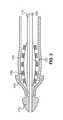
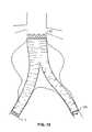
図1は、本発明によるデバイスの遠位端部を示す図である。(図示しないガイドワイヤのための)ガイドワイヤ用内腔(guidewire lumen)100は、バルーン120を膨張させるためのバルーン膨張用内腔(balloon dilation lumen)110に付随する。バルーン120の周囲には、ステント130が配されており、ステントは圧縮した状態で図示されている。グラフト140は、ステント130の上に配されており、可剥性鎖編み状シース150によって圧縮状態に保たれた状態で図示されている。グラフトに適した素材は、当業者にとっては周知であり、例えば、編まれたポリエステル(woven polyester)および成形され膨らまされたポリテトラフルオロエチレン(molded expanded polytetrafluoroethylene)がある。 FIG. 1 shows the distal end of a device according to the invention. A guidewire lumen 100 (for a guidewire not shown) is associated with a
柔らかい弾性チューブ(soft elastic tube)160も図示されており、これは、カテーテル先端部170とグラフト140の間に配されている。柔らかい弾性チューブ160は、丸みを帯びたカテーテル先端部170と組み合わされて比較的なだらかで、容易に挿入可能な端部をデバイス全体に与えている。軟らかな弾性チューブ160は、一般にシリコーン製である。それゆえ、カテーテルおよびその構成要素がガイドワイヤに沿って人体管腔を通る際の、管腔の損傷は最小化される。 A soft
図2は、可剥性鎖編み状シース150が取り除かれている点を除き、図1と同一の図である。本図においてグラフト140は、弛緩した状態の構成にまで膨張することが可能である。この、弛緩した状態の構成は、可剥性鎖編み状シース150による拘束がグラフト140に作用しなければ実現されるであろう状態の構成である。可剥性鎖編み状シース150がグラフト140の上方の所定の場所にない状態でデバイスを人体管腔内へ挿入すれば、挿入により患者は、さらに多大な損傷を被る。可剥性鎖編み状シース150がなければ、グラフト140は膨張可能となり、よりゆったりとして、大きな、そして、より扱いにくいプロファイルとなってデバイス全体を挿入する際の容易性が損なわれる。可剥性鎖編み状シース150を使用しない場合に生じるであろう問題点には、移植が望まれている場所へ通じている比較的曲がりくねった管路をカテーテルが進む際にグラフト140がねじれたり、変形したりすることが含まれる。処置されるべき病んだ管腔が大動脈瘤である場合、上記問題点は、実際、全くそのとおりである。 FIG. 2 is the same view as FIG. 1 except that the peelable chain braided
図3は、バルーン120が僅かに膨張している点を除いて図2と同一の図である。特に本図では、バルーン120が外側に向かって膨張するに従ってグラフト140の遠位端が、柔らかい弾性チューブ160下方から引き出されることが示される。図4は、バルーン120は完全に膨張し、ステント130およびグラフト140が管腔(図示せず)内部で所定の位置にある状態を示す。柔らかい弾性チューブ160は、今や、グラフト140の直径の内側に存在する。(この時点では直径の内部にある必要は無いが、カテーテルまたは送達デバイスが留置場所から取り除かれる時には、グラフト140の内側から取り除くことが可能となる。)図5は、収縮したバルーン120、および、図中の矢印の方向に取り除かれる用意の整ったデバイスが示されている。 FIG. 3 is the same view as FIG. 2 except that the
また、本発明は、治療を要する血管を治療するためのグラフトシステムを挿入する方法を含んでいる。その方法は、血管内に、本発明に係るグラフトシステムが含まれるカテーテルを、治療を要する位置まで挿入するステップ、引き紐を引っ張って可剥性鎖編み状シースを解いてグラフトを膨張可能とするステップ、ステントを膨張させてステントおよびグラフトを血管内部で固定するステップ、ならびに、その後でカテーテルを取り除くステップを有する。 The present invention also includes a method of inserting a graft system for treating a blood vessel in need of treatment. The method includes the steps of inserting a catheter containing a graft system according to the present invention into a blood vessel to a position requiring treatment, and pulling the pull string to release the peelable braided sheath to allow the graft to expand. Having a step of expanding the stent to secure the stent and graft within the blood vessel, and then removing the catheter.
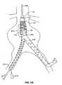
図6は、大動脈瘤内部におけるデバイスの初期的留置を示す図である。先ず、周知の方法に従い、ガイドワイヤ600が挿入される。そして、デバイスを保持するカテーテルは、図6に示されるような位置までガイドワイヤ600に沿って送られる。カテーテル先端部170は、柔らかいチューブ160の遠位に図示され、また、ステント130は、グラフト140の遠位端に配されている。可剥性鎖編み状シース150は、第1腸骨動脈脚部620およびグラフト末端領域(遠位領域)630(これは、グラフト140の分岐していない領域を指す。)に渡って配される。結節部640は、可剥性鎖編み状シース150に沿って配され、これによって可剥性鎖編み状シース150は、引き紐650が引っ張られるまで所定の場所に保持される。可剥性鎖編み状シース150があることで、グラフト140は減縮した状態の直径に保たれ、よって、デバイスがガイドワイヤ600を覆いながら進行しやすくなる。これは、上述の通りである。 FIG. 6 shows the initial placement of the device inside the aortic aneurysm. First, the
可剥性鎖編み状シースをグラフト140の上部、所定の位置に縛りつける方法および製品は周知である。そういった方法および製品に、ストレッカー(Strecker)に付与された米国特許第6,019,785号明細書に詳細に開示された内容が含まれる。この明細書を参照することにより、その内容は、本願明細書中に含まれるものとする。これらの方法および製品では、執刀医によって1本の引き紐が引っ張られると、シースがほどけて、または、解かれ、グラフト部材が、弛緩した構成および膨張した構成を取ることが可能となる。 Methods and products for tying the peelable chain braided sheath to the top of the
図6および図7に図示するように、例えば、本実施形態においては反対側のリム(肢部)(limb)は可剥性鎖編み状シースで覆われていない。図7は、把持用わな(grasping snare)670を図示しており、これは、反対側のリム660を腸骨動脈に引き入れて二股状デバイスに望ましい留置をもたらす。反対側のリム660が所定の位置に達すれば、図8Aに示す構成が実現される。別の実施形態においては、把持用わな670が不要であってもよい。そのような別の実施形態において、デバイスは、その最終的な留置場所よりも遠位にあるポイントまで送られ、よって反対側のリム660の末端が大動脈分岐部を通過する。それから、プロテーゼの完全な膨張の前に、デバイス全体を遠位に移動させ、その際に反対側のリム660をそれぞれの腸骨動脈へ誘導する。 As shown in FIGS. 6 and 7, for example, in the present embodiment, the opposite rim is not covered with a peelable chain braided sheath. FIG. 7 illustrates a grasping
別の実施形態においては、除去可能なシースによって異なるグラフトの部分を覆ってもよい。例えば、図8Bは、グラフトの全てを可剥性鎖編み状シース150で覆った実施形態を示しており、図8Cは、グラフトの末端(遠位)領域630のみを可剥性鎖編み状シース630で覆った実施形態を示している。 In another embodiment, different graft portions may be covered by a removable sheath. For example, FIG. 8B shows an embodiment in which all of the graft is covered with a peelable chain braided
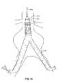
図9は、引き紐650を引き取るステップを図示しており、このステップによって可剥性鎖編み状シース150が解かれる。本発明においては、可剥性鎖編み状シースが解かれれば、もはやグラフト140を拘束するものはなく、グラフト140は、その中間的非圧縮状態にまで膨張できる。膨張の際、グラフト140は、その長さが幾分短くなる。図10は、可剥性鎖編み状シースが完全に取り除かれて、グラフト140が動脈瘤内部において完全に弛緩した状態を図示している。特に、この実施形態およびこの図において、ステント130は、この時点で可剥性鎖編み状シース150の除去によるグラフト140の相対的な短縮化のために遠位末端部が部分的に露出している。しかしながら、他の実施形態についても考察すると、他の実施形態においては、デザインおよびグラフトの素材を選択して、留置および膨張の後であってもステントが完全に覆われた状態に保つ場合も含まれる。 FIG. 9 illustrates the step of pulling the
可剥性鎖編み状シース150は取り除かれ、そしてグラフトが、弛緩状態の寸法を示せば最終的な調整を実施することで、デバイスの動脈瘤内における精確な位置決めが実施できる。これは周知の可視化技術を用いて行われる。これには、蛍光透視法による位置決め(fluoroscopic positioning)用に、グラフトもしくはステントの上に、もしくは、沿って配された放射線不透過性マーカの使用が含まれる。最終的な留置が完了すれば、ステントを膨張させてデバイスを固定することができる。 The strippable braided
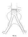
図11は、留置処置における次のステップを図示している。ここでは、バルーン120が膨張してステント130を膨らまし、プロテーゼを完全に膨らんだ状態にまで膨張させて動脈瘤の頸状部(aneurysm neck portion)をデバイスで閉塞する。本実施形態においては、ステント130が柔らかいノーズ160の領域内まで膨張し、柔らかいノーズ(soft nose)160も膨張する。ステント130が完全に膨張すれば、バルーン120は収縮されてカテーテルが取り除かれ、ステント130は動脈瘤頸状部にとどまり、グラフト140の血流受け入れの準備が整う。この状態を図12に図示する。 FIG. 11 illustrates the next step in the indwelling procedure. Here, the
図13は、最終的なステップを示す。ここでは、グラフト140を幾分圧縮し、例えば、パルス状の血流(pulsetile blood flow)および一時的移動(temporal migration)による移動の余裕を認めた後、グラフト140の末端部をそれぞれの腸骨動脈壁部に取り付ける。本実施形態においては、単に例示を目的として、第1腸骨動脈脚部620は、ステント710により所定の位置でステント留置され、また、反対側のリム660は、縫合糸700で所定の位置に縫合される。 FIG. 13 shows the final step. Here, the
図13に示す実施形態においては、ステント130とグラフト140とはただ摩擦によって結合しており、グラフト140は、ステント130と大動脈壁部との間で効果的に挟まれている。随意的には、そして、好ましくは、グラフト140は、ステント130に取り付けられてもよい。この取付けを行うための方法は幾つか知られており、それには、縫合、接着(gluing)、および、その他の、2つを一緒に繋ぎ止める手法が含まれる。このことは、腸骨動脈脚部の一方または両方の末端部において用いられるステントにも当て嵌まることである。 In the embodiment shown in FIG. 13, the
さらに別の実施形態において、機械式膨張手段、例えば、強制的にグラフトを膨らますためのプッシュロッド駆動式カム、または、スポークでできた傘状の網目構造体(umbrella spoke network)が、支持用ステントを伴って、または、伴わずに、グラフトをその完全に膨張した構成に膨らますために用いられてもよい。また、プロテーゼは、様々な取付け手段によって、プロテーゼのいずれの端部で周囲の管腔に固定されてもよい。取付け手段には、これらに限定されないが、ステープル(staple)、縫合糸、ステント、有刺ステント(stents with barbs)、可変形T頭プラスチック・ファスナ(deformable T-head plastic fastener)、等が含まれる。 In yet another embodiment, a mechanical expansion means, such as a push rod driven cam for forcibly inflating the graft, or an umbrella spoke network made of spokes is provided on the supporting stent. May or may not be used to inflate the graft to its fully expanded configuration. The prosthesis may also be secured to the surrounding lumen at either end of the prosthesis by various attachment means. Attachment means include, but are not limited to, staples, sutures, stents, stents with barbs, deformable T-head plastic fasteners, and the like. .
したがって、特定の実施形態を参照し、例示および説明を行っているが、本発明は、紹介した実施形態およびその詳細に限定されるものではない。むしろ、付随する特許請求の範囲は、全ての実施形態、および、これら実施形態から構成可能な変形例を包含する。これら全ての実施形態および変形例も、やはり本発明の本来の思想および範囲に含まれる。 Thus, although illustrated and described with reference to particular embodiments, the invention is not limited to the embodiments introduced and details thereof. Rather, the appended claims encompass all embodiments and modifications that can be made from these embodiments. All of these embodiments and modifications are also included in the original idea and scope of the present invention.
100 ・・・ ガイドワイヤ用内腔
110 ・・・ バルーン膨張用内腔
120 ・・・ バルーン
130 ・・・ ステント
140 ・・・ グラフト
150 ・・・ 可剥性鎖編み状シース
160 ・・・ 柔らかい弾性チューブ
170 ・・・ カテーテル先端部
600 ・・・ ガイドワイヤ
620 ・・・ 第1腸骨動脈脚部
630 ・・・ グラフト末端領域
640 ・・・ 結節部
650 ・・・ 引き紐
660 ・・・ 反対側のリム
670 ・・・ 把持用わな
700 ・・・ 縫合糸
710 ・・・ ステント
DESCRIPTION OF
Claims (36)
Translated fromJapanese中心軸と、経管腔内内挿的送達のための半径方向に圧縮された第1の構成部と、半径方向に膨らんだ第2の構成部とを含む管状グラフトと、
前記グラフトを半径方向に膨らんだ構成部まで膨らませる半径方向膨張手段と、
前記第1の構成部の前記グラフトの少なくとも一部分に周設され、前記グラフトが膨張できるように除去可能な可剥性シースとを有することを特徴とするシステム。A system for intraluminal interstitial delivery and placement of a prosthesis within a human body lumen, comprising:
A tubular graft including a central axis, a radially compressed first component for transluminal endoscopic delivery, and a radially inflated second component;
Radial expansion means for inflating the graft to a radially expanded component;
A system comprising a peelable sheath circumferentially disposed on at least a portion of the graft of the first component and removable to allow the graft to expand.
前記引き紐を引き戻すことで、前記シースが除去されることを特徴とする、請求項1に記載のシステム。In addition, it has a drawstring extending from the peelable sheath,
The system according to claim 1, wherein the sheath is removed by pulling back the drawstring.
前記引き紐を引き戻すことで、前記シースが解かれて除去されることを特徴とする、請求項3に記載のシステム。The peelable sheath is chain-knitted, and
4. The system of claim 3, wherein the sheath is unwound and removed by pulling back the drawstring.
バルーン膨張性ステントは、前記末端大動脈領域内に配され、かつ、
前記可剥性シースは、可剥性鎖編み状シースであり、前記末端領域、および、前記2つの末端脚部のただ1つのまわりに延在することを特徴とする、大動脈瘤治療に用いる請求項1に記載のシステム。The graft is a bifurcated graft having one terminal aortic region and two terminal iliac arterial legs;
A balloon expandable stent is disposed within the distal aorta region; and
The strippable sheath is a strippable braided sheath and extends around only one of the distal region and the two distal legs, for use in treating an aortic aneurysm Item 4. The system according to Item 1.
管状グラフトと、
前記グラフトの少なくとも一部分に配された管状ステントであり、前記ステントおよびグラフトが、共通の中心軸、経管腔内的送達のための半径方向に圧縮された第1の構成と、半径方向に膨らんだ第2の構成とを有する、管状ステントと、
前記ステントおよびグラフトを前記の半径方向に膨らんだ構成まで膨らませる半径方向膨張手段と、
前記第1の構成の前記グラフトの少なくとも一部分に周設され、前記グラフトおよびステントが膨張できるように除去可能な可剥性シースと、
前記可剥性シースから延在する引き紐とを有し、
前記引き紐を引き戻すことで、前記シースが解かれることを特徴とするシステム。A system for intraluminal interstitial delivery and placement of a prosthesis within a human body lumen, comprising:
A tubular graft;
A tubular stent disposed on at least a portion of the graft, wherein the stent and graft are radially inflated with a common central axis, a radially compressed first configuration for intraluminal delivery; A tubular stent having a second configuration;
Radial expansion means for expanding the stent and graft to the radially expanded configuration;
A peelable sheath disposed around at least a portion of the graft in the first configuration and removable to allow the graft and stent to expand;
A drawstring extending from the peelable sheath;
The system is characterized in that the sheath is unwound by pulling back the drawstring.
前記引き紐を引き戻すことで、前記シースが解かれて除去されることを特徴とする、請求項13に記載のシステム。The peelable sheath is chain-knitted, and
14. The system of claim 13, wherein the sheath is unwound and removed by pulling back the drawstring.
バルーン膨張性ステントは、前記末端大動脈領域内に配され、かつ、
前記可剥性シースは、可剥性鎖編み状シースであり、前記末端領域、および、前記2つの末端脚部のただ1つのまわりに延在することを特徴とする、大動脈瘤治療用の請求項13に記載のシステム。The graft is a bifurcated graft having one terminal aortic region and two terminal iliac arterial legs;
A balloon expandable stent is disposed within the distal aorta region; and
Claim for treating an aortic aneurysm, wherein the peelable sheath is a peelable chain braided sheath and extends around only one of the distal region and the two distal legs. Item 14. The system according to Item 13.
末端領域、および、2つの脚部を有する二股状グラフトと、
前記末端領域内の一部分に配された膨張性ステントと、
前記末端領域、および、前記2つの脚部の1つに周設され、前記グラフトの膨張を可能にするために除去可能な可剥性シースと、
前記可剥性鎖編み状シースから延在する引き紐とを有し、
前記引き紐を引き戻すことで、前記シースが除去されることを特徴とするシステム。A bifurcated graft system for intraluminal delivery into an aortic aneurysm in need of treatment, comprising:
A bifurcated graft having a distal region and two legs;
An expandable stent disposed in a portion within the distal region;
A strippable sheath around the distal region and one of the two legs and removable to allow expansion of the graft;
A pull string extending from the strippable braided sheath;
The system wherein the sheath is removed by pulling back the drawstring.
第1端部と、前記第1端部に隣接して配された中間領域とを有し、大動脈への挿入のための減縮されたプロファイルから膨張したプロファイルへ自己膨張可能なグラフトと、
前記グラフトの前記第1端部を前記大動脈に固定するための固定手段であり、前記固定手段の前記大動脈内への経管腔内内挿的送達が可能な第1直径、および、前記グラフトの前記第1端部を前記大動脈へ固定するための、膨張した第2直径を有する固定手段と、
固定手段、および、グラフトを、前記半径方向に膨張した構成に膨張させるための半径方向膨張手段と、
前記グラフトの少なくとも一部分を覆い、前記グラフトを前記減縮されたプロファイルに保つ可剥性シースと、
前記可剥性シースから延在し、引き戻すことにより前記可剥性シースの除去、および、その結果生じる前記グラフトの減縮されたプロファイルから膨張したプロファイルへの膨張を可能にする、少なくとも1つの引き紐とを有することを特徴とするシステム。An aortic graft system delivered intraluminally to treat an abdominal aortic aneurysm in the aorta having two iliac arteries associated with the aorta at the aortic bifurcation,
A graft having a first end and an intermediate region disposed adjacent to the first end and capable of self-expanding from a reduced profile for insertion into the aorta to an expanded profile;
A fixing means for fixing the first end of the graft to the aorta, a first diameter capable of transluminal insertion of the fixing means into the aorta, and the graft A securing means having an expanded second diameter for securing the first end to the aorta;
Fixing means, and radial expansion means for inflating the graft to said radially expanded configuration;
A peelable sheath covering at least a portion of the graft and maintaining the graft in the reduced profile;
At least one drawstring that extends from the peelable sheath and allows pulling back to remove the peelable sheath and consequent expansion of the graft from a reduced profile to an expanded profile The system characterized by having.
カテーテルを血管へのアクセス位置から血管に挿入して治療を要する留置位置へ送るカテーテル挿入ステップであって、
前記カテーテルが前記カテーテルに配されたグラフトシステムを備え、
前記グラフトシステムが、
グラフトに周囲を取り囲まれ、中心に配されたプッシュワイヤと、
前記管状グラフトを前記血管内に固定するための固定手段と、
前記グラフトの少なくとも一部分に周設された、除去することで前記グラフトの膨張を可能にする可剥性シースと、
前記可剥性シースから前記アクセス位置まで延在する引き紐であり、前記引き紐を引き戻すことで前記シースが除去される引き紐とを有する、カテーテル挿入ステップと、
前記引き紐を引き戻して前記可剥性シースを除去し、前記グラフトの膨張を可能にするステップと、
前記グラフトを前記血管内部に固定するステップと、
前記カテーテルを除去するステップとを有することを特徴とする方法。A method of inserting a graft system into a blood vessel that requires treatment,
A catheter insertion step in which the catheter is inserted into the blood vessel from the access position to the blood vessel and sent to an indwelling position requiring treatment,
The catheter comprises a graft system disposed on the catheter;
The graft system comprises:
A push wire surrounded by the graft and placed in the center;
Fixing means for fixing the tubular graft in the blood vessel;
A peelable sheath around the at least a portion of the graft that allows the graft to expand by removal;
A catheter insertion step comprising: a pull string extending from the peelable sheath to the access position, wherein the pull string pulls the sheath to remove the sheath;
Pulling back the drawstring to remove the peelable sheath and allowing the graft to expand;
Securing the graft within the blood vessel;
Removing the catheter.
前記固定するステップは、前記カテーテルに配されたバルーンを膨張させて前記バルーン膨張性ステントを膨張させるステップを含んでいることを特徴とする、請求項27に記載の方法。The securing means comprises a balloon expandable stent; and
28. The method of claim 27, wherein the securing step includes inflating a balloon disposed on the catheter to inflate the balloon-expandable stent.
前記グラフトは、分岐して1つの末端領域および2つの末端脚部を備え、
前記可剥性シースは、前記末端領域、および、前記2つの末端脚部のただ1つの周囲に延在することを特徴とする、請求項27に記載の方法。The blood vessel requiring treatment is a branched blood vessel,
The graft is bifurcated and has one end region and two end legs,
28. The method of claim 27, wherein the peelable sheath extends around only one of the distal region and the two distal legs.
さらに、前記引き戻すためのステップの前に、前記可剥性鎖編み状シースに覆われていない前記脚部を前記カテーテルの挿入に使用されていない腸骨動脈へ引き入れるステップを有する、請求項27に記載の方法。The insertion step is characterized by inserting through one iliac artery;
28. The method according to claim 27, further comprising the step of drawing the leg not covered by the strippable braided sheath into an iliac artery not used for insertion of the catheter prior to the step of pulling back. The method described.
カテーテルを血管へのアクセス位置から血管に挿入して治療を要する留置位置へ送るカテーテル挿入ステップであって、
前記カテーテルが前記カテーテルに配されたグラフトシステムを備え、
前記グラフトシステムが、
グラフトに周囲を取り囲まれ、中心に配されたプッシュワイヤと、
前記グラフトの少なくとも一部分に配された膨張性ステントと、
前記グラフトの少なくとも一部分に周設された、除去することで前記グラフトおよびステントの膨張を可能にする可剥性鎖編み状シースと、
前記可剥性鎖編み状シースから前記アクセス位置まで延在する引き紐であり、前記引き紐を引き戻すことで前記シースが解かれて除去される引き紐とを有する、カテーテル挿入ステップと、
前記引き紐を引き戻して前記可剥性鎖編み状シースを解いて除去し、前記グラフトの膨張を可能にするステップと、
前記ステントを膨張させて前記ステントおよび前記グラフトを前記血管内部に固定するステップと、
前記カテーテルを除去するステップとを有する方法。A method of inserting a graft system into a blood vessel that requires treatment,
A catheter insertion step in which the catheter is inserted into the blood vessel from the access position to the blood vessel and sent to an indwelling position requiring treatment,
The catheter comprises a graft system disposed on the catheter;
The graft system comprises:
A push wire surrounded by the graft and placed in the center;
An expandable stent disposed on at least a portion of the graft;
A strippable braided sheath around at least a portion of the graft that allows the graft and stent to expand upon removal;
A catheter insertion step, comprising: a pull string extending from the peelable chain braided sheath to the access position, wherein the pull string pulls the pull string back to remove the sheath and remove it;
Pulling back the drawstring to unwind and remove the strippable braided sheath, allowing the graft to expand; and
Expanding the stent to secure the stent and the graft within the blood vessel;
Removing the catheter.
前記膨張させるステップは、前記カテーテルに配されたバルーンを膨張させるステップを含んでいることを特徴とする、請求項33に記載の方法。The stent is a balloon expandable stent; and
34. The method of claim 33, wherein the inflating includes inflating a balloon disposed on the catheter.
前記グラフトは、分岐して1つの末端領域および2つの末端脚部を備え、
前記可剥性鎖編み状シースは、前記末端領域、および、前記2つの末端脚部のただ1つの周囲に延在することを特徴とする、請求項33に記載の方法。The blood vessel requiring treatment is an aortic aneurysm,
The graft is bifurcated and has one end region and two end legs,
34. The method of claim 33, wherein the peelable chain braided sheath extends around the end region and only one of the two end legs.
さらに、前記引き戻すためのステップの前に、前記可剥性鎖編み状シースに覆われていない前記脚部を前記カテーテルの挿入に使用されていない腸骨動脈へ引き入れるステップを有する、請求項35に記載の方法。
The insertion step is characterized by inserting through one iliac artery;
36. The method of claim 35, further comprising the step of drawing the leg not covered by the strippable braided sheath into an iliac artery not used for insertion of the catheter prior to the step of pulling back. The method described.
Applications Claiming Priority (2)
| Application Number | Priority Date | Filing Date | Title |
|---|---|---|---|
| US10/176,834US20030236565A1 (en) | 2002-06-21 | 2002-06-21 | Implantable prosthesis |
| PCT/US2003/015242WO2004000169A1 (en) | 2002-06-21 | 2003-05-15 | Implantable prosthesis |
Publications (2)
| Publication Number | Publication Date |
|---|---|
| JP2005530550Atrue JP2005530550A (en) | 2005-10-13 |
| JP4347803B2 JP4347803B2 (en) | 2009-10-21 |
Family
ID=29734231
Family Applications (1)
| Application Number | Title | Priority Date | Filing Date |
|---|---|---|---|
| JP2004515682AExpired - Fee RelatedJP4347803B2 (en) | 2002-06-21 | 2003-05-15 | Implantable prosthesis |
Country Status (9)
| Country | Link |
|---|---|
| US (2) | US20030236565A1 (en) |
| EP (1) | EP1515668B1 (en) |
| JP (1) | JP4347803B2 (en) |
| AT (1) | ATE380527T1 (en) |
| AU (1) | AU2003234578A1 (en) |
| CA (1) | CA2483871A1 (en) |
| DE (1) | DE60318052T2 (en) |
| ES (1) | ES2298518T3 (en) |
| WO (1) | WO2004000169A1 (en) |
Cited By (5)
| Publication number | Priority date | Publication date | Assignee | Title |
|---|---|---|---|---|
| JP2015091413A (en)* | 2009-03-13 | 2015-05-14 | ボルトン メディカル インコーポレイテッド | System and method for deploying an endoluminal prosthesis at a surgical site |
| US11596537B2 (en) | 2003-09-03 | 2023-03-07 | Bolton Medical, Inc. | Delivery system and method for self-centering a proximal end of a stent graft |
| JP2023521082A (en)* | 2020-04-06 | 2023-05-23 | ダブリュ.エル.ゴア アンド アソシエイツ,インコーポレイティド | DELIVERY SYSTEM WITH DEVICE DEPLOYMENT FEATURES AND RELATED METHODS |
| US12232992B2 (en) | 2013-03-15 | 2025-02-25 | Bolton Medical, Inc. | Hemostasis valve and delivery systems |
| US12409055B2 (en) | 2020-06-24 | 2025-09-09 | Bolton Medical, Inc. | Anti-backspin component for vascular prosthesis delivery device |
Families Citing this family (110)
| Publication number | Priority date | Publication date | Assignee | Title |
|---|---|---|---|---|
| US6951572B1 (en)* | 1997-02-20 | 2005-10-04 | Endologix, Inc. | Bifurcated vascular graft and method and apparatus for deploying same |
| US6240616B1 (en) | 1997-04-15 | 2001-06-05 | Advanced Cardiovascular Systems, Inc. | Method of manufacturing a medicated porous metal prosthesis |
| US10028851B2 (en) | 1997-04-15 | 2018-07-24 | Advanced Cardiovascular Systems, Inc. | Coatings for controlling erosion of a substrate of an implantable medical device |
| US6776792B1 (en) | 1997-04-24 | 2004-08-17 | Advanced Cardiovascular Systems Inc. | Coated endovascular stent |
| US8034100B2 (en) | 1999-03-11 | 2011-10-11 | Endologix, Inc. | Graft deployment system |
| US6261316B1 (en) | 1999-03-11 | 2001-07-17 | Endologix, Inc. | Single puncture bifurcation graft deployment system |
| US6783793B1 (en) | 2000-10-26 | 2004-08-31 | Advanced Cardiovascular Systems, Inc. | Selective coating of medical devices |
| WO2002039888A2 (en)* | 2000-11-15 | 2002-05-23 | Endologix, Inc. | Implantable vascular graft |
| US6962598B2 (en) | 2001-07-02 | 2005-11-08 | Rubicon Medical, Inc. | Methods, systems, and devices for providing embolic protection |
| US6951570B2 (en) | 2001-07-02 | 2005-10-04 | Rubicon Medical, Inc. | Methods, systems, and devices for deploying a filter from a filter device |
| US6997939B2 (en) | 2001-07-02 | 2006-02-14 | Rubicon Medical, Inc. | Methods, systems, and devices for deploying an embolic protection filter |
| US7285304B1 (en) | 2003-06-25 | 2007-10-23 | Advanced Cardiovascular Systems, Inc. | Fluid treatment of a polymeric coating on an implantable medical device |
| US6863683B2 (en) | 2001-09-19 | 2005-03-08 | Abbott Laboratoris Vascular Entities Limited | Cold-molding process for loading a stent onto a stent delivery system |
| US7695446B2 (en) | 2002-12-02 | 2010-04-13 | Gi Dynamics, Inc. | Methods of treatment using a bariatric sleeve |
| WO2004049982A2 (en) | 2002-12-02 | 2004-06-17 | Gi Dynamics, Inc. | Bariatric sleeve |
| US7608114B2 (en) | 2002-12-02 | 2009-10-27 | Gi Dynamics, Inc. | Bariatric sleeve |
| US7766973B2 (en) | 2005-01-19 | 2010-08-03 | Gi Dynamics, Inc. | Eversion resistant sleeves |
| US7025791B2 (en) | 2002-12-02 | 2006-04-11 | Gi Dynamics, Inc. | Bariatric sleeve |
| US7678068B2 (en) | 2002-12-02 | 2010-03-16 | Gi Dynamics, Inc. | Atraumatic delivery devices |
| US11259945B2 (en) | 2003-09-03 | 2022-03-01 | Bolton Medical, Inc. | Dual capture device for stent graft delivery system and method for capturing a stent graft |
| US9198786B2 (en) | 2003-09-03 | 2015-12-01 | Bolton Medical, Inc. | Lumen repair device with capture structure |
| US8500792B2 (en) | 2003-09-03 | 2013-08-06 | Bolton Medical, Inc. | Dual capture device for stent graft delivery system and method for capturing a stent graft |
| US8292943B2 (en) | 2003-09-03 | 2012-10-23 | Bolton Medical, Inc. | Stent graft with longitudinal support member |
| US7763063B2 (en) | 2003-09-03 | 2010-07-27 | Bolton Medical, Inc. | Self-aligning stent graft delivery system, kit, and method |
| US20070198078A1 (en) | 2003-09-03 | 2007-08-23 | Bolton Medical, Inc. | Delivery system and method for self-centering a Proximal end of a stent graft |
| US20080264102A1 (en) | 2004-02-23 | 2008-10-30 | Bolton Medical, Inc. | Sheath Capture Device for Stent Graft Delivery System and Method for Operating Same |
| US7198675B2 (en) | 2003-09-30 | 2007-04-03 | Advanced Cardiovascular Systems | Stent mandrel fixture and method for selectively coating surfaces of a stent |
| US8057420B2 (en) | 2003-12-09 | 2011-11-15 | Gi Dynamics, Inc. | Gastrointestinal implant with drawstring |
| AU2004305450B2 (en) | 2003-12-09 | 2009-01-08 | Gi Dynamics, Inc. | Intestinal sleeve |
| US7563324B1 (en) | 2003-12-29 | 2009-07-21 | Advanced Cardiovascular Systems Inc. | System and method for coating an implantable medical device |
| US7553377B1 (en) | 2004-04-27 | 2009-06-30 | Advanced Cardiovascular Systems, Inc. | Apparatus and method for electrostatic coating of an abluminal stent surface |
| US8241554B1 (en) | 2004-06-29 | 2012-08-14 | Advanced Cardiovascular Systems, Inc. | Method of forming a stent pattern on a tube |
| ATE506042T1 (en) | 2004-07-09 | 2011-05-15 | Gi Dynamics Inc | DEVICES FOR PLACEMENT OF A GASTROINTESTINAL SLEEVE |
| US7731890B2 (en) | 2006-06-15 | 2010-06-08 | Advanced Cardiovascular Systems, Inc. | Methods of fabricating stents with enhanced fracture toughness |
| US8778256B1 (en) | 2004-09-30 | 2014-07-15 | Advanced Cardiovascular Systems, Inc. | Deformation of a polymer tube in the fabrication of a medical article |
| US9283099B2 (en) | 2004-08-25 | 2016-03-15 | Advanced Cardiovascular Systems, Inc. | Stent-catheter assembly with a releasable connection for stent retention |
| US7229471B2 (en) | 2004-09-10 | 2007-06-12 | Advanced Cardiovascular Systems, Inc. | Compositions containing fast-leaching plasticizers for improved performance of medical devices |
| EP1799145B1 (en) | 2004-09-17 | 2016-12-21 | GI Dynamics, Inc. | Gastrointestinal anchor |
| CN101094623B (en)* | 2004-09-28 | 2012-08-08 | 科迪斯公司 | Thin film medical device and delivery system |
| US7632307B2 (en) | 2004-12-16 | 2009-12-15 | Advanced Cardiovascular Systems, Inc. | Abluminal, multilayer coating constructs for drug-delivery stents |
| US7588596B2 (en) | 2004-12-29 | 2009-09-15 | Scimed Life Systems, Inc. | Endoluminal prosthesis adapted to resist migration and method of deploying the same |
| US7771382B2 (en) | 2005-01-19 | 2010-08-10 | Gi Dynamics, Inc. | Resistive anti-obesity devices |
| US7918880B2 (en)* | 2005-02-16 | 2011-04-05 | Boston Scientific Scimed, Inc. | Self-expanding stent and delivery system |
| US7381048B2 (en) | 2005-04-12 | 2008-06-03 | Advanced Cardiovascular Systems, Inc. | Stents with profiles for gripping a balloon catheter and molds for fabricating stents |
| US7291166B2 (en) | 2005-05-18 | 2007-11-06 | Advanced Cardiovascular Systems, Inc. | Polymeric stent patterns |
| US7976488B2 (en) | 2005-06-08 | 2011-07-12 | Gi Dynamics, Inc. | Gastrointestinal anchor compliance |
| US7297758B2 (en) | 2005-08-02 | 2007-11-20 | Advanced Cardiovascular Systems, Inc. | Method for extending shelf-life of constructs of semi-crystallizable polymers |
| US7476245B2 (en) | 2005-08-16 | 2009-01-13 | Advanced Cardiovascular Systems, Inc. | Polymeric stent patterns |
| US7867547B2 (en) | 2005-12-19 | 2011-01-11 | Advanced Cardiovascular Systems, Inc. | Selectively coating luminal surfaces of stents |
| US7964210B2 (en) | 2006-03-31 | 2011-06-21 | Abbott Cardiovascular Systems Inc. | Degradable polymeric implantable medical devices with a continuous phase and discrete phase |
| US8003156B2 (en) | 2006-05-04 | 2011-08-23 | Advanced Cardiovascular Systems, Inc. | Rotatable support elements for stents |
| US7761968B2 (en) | 2006-05-25 | 2010-07-27 | Advanced Cardiovascular Systems, Inc. | Method of crimping a polymeric stent |
| US7951194B2 (en) | 2006-05-26 | 2011-05-31 | Abbott Cardiovascular Sysetms Inc. | Bioabsorbable stent with radiopaque coating |
| US20130325107A1 (en) | 2006-05-26 | 2013-12-05 | Abbott Cardiovascular Systems Inc. | Stents With Radiopaque Markers |
| US20070282434A1 (en)* | 2006-05-30 | 2007-12-06 | Yunbing Wang | Copolymer-bioceramic composite implantable medical devices |
| US8603530B2 (en) | 2006-06-14 | 2013-12-10 | Abbott Cardiovascular Systems Inc. | Nanoshell therapy |
| US8048448B2 (en) | 2006-06-15 | 2011-11-01 | Abbott Cardiovascular Systems Inc. | Nanoshells for drug delivery |
| US8333000B2 (en) | 2006-06-19 | 2012-12-18 | Advanced Cardiovascular Systems, Inc. | Methods for improving stent retention on a balloon catheter |
| US8017237B2 (en) | 2006-06-23 | 2011-09-13 | Abbott Cardiovascular Systems, Inc. | Nanoshells on polymers |
| US7819836B2 (en) | 2006-06-23 | 2010-10-26 | Gi Dynamics, Inc. | Resistive anti-obesity devices |
| US7794776B1 (en) | 2006-06-29 | 2010-09-14 | Abbott Cardiovascular Systems Inc. | Modification of polymer stents with radiation |
| AU2007276703A1 (en)* | 2006-07-21 | 2008-01-24 | Murray Vascular Pty Limited | Stent assembly |
| US8016879B2 (en) | 2006-08-01 | 2011-09-13 | Abbott Cardiovascular Systems Inc. | Drug delivery after biodegradation of the stent scaffolding |
| US9173733B1 (en) | 2006-08-21 | 2015-11-03 | Abbott Cardiovascular Systems Inc. | Tracheobronchial implantable medical device and methods of use |
| US20080065044A1 (en)* | 2006-09-08 | 2008-03-13 | Abbott Cardiovascular Systems Inc. | Bioactive agent-containing implantable rings |
| US20080071343A1 (en)* | 2006-09-15 | 2008-03-20 | Kevin John Mayberry | Multi-segmented graft deployment system |
| US8523931B2 (en)* | 2007-01-12 | 2013-09-03 | Endologix, Inc. | Dual concentric guidewire and methods of bifurcated graft deployment |
| US8821567B2 (en)* | 2007-02-22 | 2014-09-02 | Mohsin Saeed | Apparatus and method for implantation of a bifurcated endovascular prosthesis |
| US8801647B2 (en) | 2007-02-22 | 2014-08-12 | Gi Dynamics, Inc. | Use of a gastrointestinal sleeve to treat bariatric surgery fistulas and leaks |
| US8202528B2 (en) | 2007-06-05 | 2012-06-19 | Abbott Cardiovascular Systems Inc. | Implantable medical devices with elastomeric block copolymer coatings |
| US8048441B2 (en) | 2007-06-25 | 2011-11-01 | Abbott Cardiovascular Systems, Inc. | Nanobead releasing medical devices |
| US10646363B2 (en)* | 2007-12-27 | 2020-05-12 | Cook Medical Technologies Llc | Endovascular device delivery system |
| WO2009105699A1 (en) | 2008-02-22 | 2009-08-27 | Endologix, Inc. | Design and method of placement of a graft or graft system |
| US8236040B2 (en) | 2008-04-11 | 2012-08-07 | Endologix, Inc. | Bifurcated graft deployment systems and methods |
| CN102076281B (en) | 2008-06-30 | 2014-11-05 | 波顿医疗公司 | Systems and methods for abdominal aortic aneurysm |
| EP2520320B1 (en) | 2008-07-01 | 2016-11-02 | Endologix, Inc. | Catheter system |
| US8986361B2 (en)* | 2008-10-17 | 2015-03-24 | Medtronic Corevalve, Inc. | Delivery system for deployment of medical devices |
| US8444669B2 (en) | 2008-12-15 | 2013-05-21 | Boston Scientific Scimed, Inc. | Embolic filter delivery system and method |
| CN101836911A (en) | 2009-03-18 | 2010-09-22 | 微创医疗器械(上海)有限公司 | Collateral filmed stent |
| EP2410926A4 (en)* | 2009-03-25 | 2012-12-05 | Svelte Medical Systems Inc | BALLOON EQUIPMENT AND METHOD FOR THE PRODUCTION AND USE THEREOF |
| US20110054587A1 (en)* | 2009-04-28 | 2011-03-03 | Endologix, Inc. | Apparatus and method of placement of a graft or graft system |
| JP2012525239A (en)* | 2009-05-01 | 2012-10-22 | エンドロジックス、インク | Transcutaneous methods and devices for treating dissociation (priority information and incorporation by reference) |
| US10772717B2 (en) | 2009-05-01 | 2020-09-15 | Endologix, Inc. | Percutaneous method and device to treat dissections |
| CN101897629B (en)* | 2009-05-26 | 2013-08-07 | 上海微创医疗器械(集团)有限公司 | Branched membrane-covered support conveying system and conveying method thereof |
| WO2011002641A1 (en)* | 2009-06-30 | 2011-01-06 | Boston Scientific Scimed, Inc. | Endoprosthesis and endoprosthesis delivery system and method |
| WO2011008989A2 (en) | 2009-07-15 | 2011-01-20 | Endologix, Inc. | Stent graft |
| WO2011017123A2 (en) | 2009-07-27 | 2011-02-10 | Endologix, Inc. | Stent graft |
| US20110218608A1 (en)* | 2009-09-10 | 2011-09-08 | Novostent Corporation | Vascular Prosthesis Delivery System and Method |
| US8475513B2 (en) | 2009-12-02 | 2013-07-02 | Nedunchezian Sithian | Stent graft apparatus and method |
| US8808353B2 (en) | 2010-01-30 | 2014-08-19 | Abbott Cardiovascular Systems Inc. | Crush recoverable polymer scaffolds having a low crossing profile |
| US8568471B2 (en) | 2010-01-30 | 2013-10-29 | Abbott Cardiovascular Systems Inc. | Crush recoverable polymer scaffolds |
| US20110218617A1 (en)* | 2010-03-02 | 2011-09-08 | Endologix, Inc. | Endoluminal vascular prosthesis |
| US8632582B2 (en)* | 2010-03-25 | 2014-01-21 | Mayo Foundation For Medical Education And Research | Removable and/or retrievable stents and kits |
| US20120109279A1 (en) | 2010-11-02 | 2012-05-03 | Endologix, Inc. | Apparatus and method of placement of a graft or graft system |
| US9393100B2 (en) | 2010-11-17 | 2016-07-19 | Endologix, Inc. | Devices and methods to treat vascular dissections |
| US9155612B2 (en)* | 2011-01-10 | 2015-10-13 | Intermountain Invention Management, Llc | Composite stent grafts for in situ assembly and related methods |
| US8808350B2 (en) | 2011-03-01 | 2014-08-19 | Endologix, Inc. | Catheter system and methods of using same |
| US8726483B2 (en) | 2011-07-29 | 2014-05-20 | Abbott Cardiovascular Systems Inc. | Methods for uniform crimping and deployment of a polymer scaffold |
| EP2846743B1 (en) | 2012-04-12 | 2016-12-14 | Bolton Medical Inc. | Vascular prosthetic delivery device |
| US9956103B2 (en) | 2013-03-11 | 2018-05-01 | DePuy Synthes Products, Inc. | Stent delivery system and method |
| US10172734B2 (en) | 2013-03-13 | 2019-01-08 | DePuy Synthes Products, Inc. | Capture tube mechanism for delivering and releasing a stent |
| AU2016207060B2 (en) | 2015-01-14 | 2018-10-18 | Cook Medical Technologies Llc | Suture and wire stent deployment system |
| WO2017004265A1 (en) | 2015-06-30 | 2017-01-05 | Endologix, Inc. | Locking assembly for coupling guidewire to delivery system |
| DE102015118854A1 (en)* | 2015-11-03 | 2017-05-04 | UroTiss Europe GmbH | Device for introducing a tissue replacement into a hollow organ |
| US10433993B2 (en) | 2017-01-20 | 2019-10-08 | Medtronic Vascular, Inc. | Valve prosthesis having a radially-expandable sleeve integrated thereon for delivery and prevention of paravalvular leakage |
| WO2019108217A1 (en) | 2017-12-01 | 2019-06-06 | C.R. Bard, Inc. | Adjustable vascular graft for custom inner diameter reduction and related methods |
| US20210161644A1 (en)* | 2017-12-18 | 2021-06-03 | George P. Teitelbaum | Branch point flow diversion device |
| EP3870105A4 (en)* | 2018-10-25 | 2022-08-03 | Endologix LLC | Bifurcated stent grafts, stents, and methods |
| FI3941392T3 (en) | 2019-03-20 | 2025-07-28 | Inqb8 Medical Tech Llc | Aortic dissection implant |
| DE102020115614A1 (en)* | 2020-06-12 | 2021-12-16 | Phenox Gmbh | Delivery system for implants for the treatment of bifurcation aneurysms |
Family Cites Families (32)
| Publication number | Priority date | Publication date | Assignee | Title |
|---|---|---|---|---|
| US7208A (en)* | 1850-03-26 | birdseye | ||
| US4140126A (en)* | 1977-02-18 | 1979-02-20 | Choudhury M Hasan | Method for performing aneurysm repair |
| US4617932A (en)* | 1984-04-25 | 1986-10-21 | Elliot Kornberg | Device and method for performing an intraluminal abdominal aortic aneurysm repair |
| US4577631A (en)* | 1984-11-16 | 1986-03-25 | Kreamer Jeffry W | Aneurysm repair apparatus and method |
| US4950227A (en)* | 1988-11-07 | 1990-08-21 | Boston Scientific Corporation | Stent delivery system |
| US5571169A (en)* | 1993-06-07 | 1996-11-05 | Endovascular Instruments, Inc. | Anti-stenotic method and product for occluded and partially occluded arteries |
| US5578071A (en)* | 1990-06-11 | 1996-11-26 | Parodi; Juan C. | Aortic graft |
| US5405378A (en)* | 1992-05-20 | 1995-04-11 | Strecker; Ernst P. | Device with a prosthesis implantable in the body of a patient |
| WO1994023669A1 (en)* | 1993-04-13 | 1994-10-27 | Boston Scientific Corporation | Prosthesis delivery system with dilating tip |
| US5464449A (en)* | 1993-07-08 | 1995-11-07 | Thomas J. Fogarty | Internal graft prosthesis and delivery system |
| JP2537751B2 (en) | 1993-12-14 | 1996-09-25 | 株式会社コバード | Draw forming food manufacturing method and apparatus |
| US6015429A (en)* | 1994-09-08 | 2000-01-18 | Gore Enterprise Holdings, Inc. | Procedures for introducing stents and stent-grafts |
| US5755770A (en)* | 1995-01-31 | 1998-05-26 | Boston Scientific Corporatiion | Endovascular aortic graft |
| US5647857A (en)* | 1995-03-16 | 1997-07-15 | Endotex Interventional Systems, Inc. | Protective intraluminal sheath |
| EP0950385A3 (en)* | 1995-12-14 | 1999-10-27 | Prograft Medical, Inc. | Stent-graft deployment apparatus and method |
| FR2748199B1 (en)* | 1996-05-02 | 1998-10-09 | Braun Celsa Sa | TRANSCUTANEOUS SURGICAL ANASTOMOSABLE VASCULAR PROSTHESIS |
| US5954764A (en)* | 1996-09-20 | 1999-09-21 | Parodi; Juan Carlos | Device for concurrently placing an endovascular expander with an endovascular prosthesis |
| US6352561B1 (en)* | 1996-12-23 | 2002-03-05 | W. L. Gore & Associates | Implant deployment apparatus |
| US6152956A (en)* | 1997-01-28 | 2000-11-28 | Pierce; George E. | Prosthesis for endovascular repair of abdominal aortic aneurysms |
| US5824055A (en)* | 1997-03-25 | 1998-10-20 | Endotex Interventional Systems, Inc. | Stent graft delivery system and methods of use |
| FR2762989B1 (en)* | 1997-05-12 | 1999-09-03 | Braun Celsa Sa | SYSTEM FOR REPAIRING AN ANATOMIC DUCT BY A PROGRESSIVE OPENING IMPLANT |
| US6235051B1 (en)* | 1997-12-16 | 2001-05-22 | Timothy P. Murphy | Method of stent-graft system delivery |
| US6395019B2 (en)* | 1998-02-09 | 2002-05-28 | Trivascular, Inc. | Endovascular graft |
| US6102918A (en)* | 1998-02-18 | 2000-08-15 | Montefiore Hospital And Medical Center | Collapsible low-profile vascular graft implantation instrument and method for use thereof |
| US6224627B1 (en)* | 1998-06-15 | 2001-05-01 | Gore Enterprise Holdings, Inc. | Remotely removable covering and support |
| US6096027A (en)* | 1998-09-30 | 2000-08-01 | Impra, Inc., A Subsidiary Of C.R. Bard, Inc. | Bag enclosed stent loading apparatus |
| US6261316B1 (en)* | 1999-03-11 | 2001-07-17 | Endologix, Inc. | Single puncture bifurcation graft deployment system |
| US6398802B1 (en)* | 1999-06-21 | 2002-06-04 | Scimed Life Systems, Inc. | Low profile delivery system for stent and graft deployment |
| US20010018609A1 (en) | 1999-08-11 | 2001-08-30 | Scott Smith | Seamless braided or spun stent cover |
| JP2001211811A (en) | 2000-01-31 | 2001-08-07 | Shin Nippon Kikai Kogyo Kk | Method of producing sweet or food squeezed in tea napkin and device therefor |
| JP2001211812A (en) | 2000-01-31 | 2001-08-07 | Shin Nippon Kikai Kogyo Kk | Device for squeezing food or sweet |
| US20030220683A1 (en)* | 2002-05-22 | 2003-11-27 | Zarouhi Minasian | Endoluminal device having barb assembly and method of using same |
- 2002
- 2002-06-21USUS10/176,834patent/US20030236565A1/ennot_activeAbandoned
- 2003
- 2003-05-15DEDE60318052Tpatent/DE60318052T2/ennot_activeExpired - Lifetime
- 2003-05-15CACA002483871Apatent/CA2483871A1/ennot_activeAbandoned
- 2003-05-15WOPCT/US2003/015242patent/WO2004000169A1/enactiveIP Right Grant
- 2003-05-15ESES03728920Tpatent/ES2298518T3/ennot_activeExpired - Lifetime
- 2003-05-15ATAT03728920Tpatent/ATE380527T1/ennot_activeIP Right Cessation
- 2003-05-15EPEP03728920Apatent/EP1515668B1/ennot_activeExpired - Lifetime
- 2003-05-15JPJP2004515682Apatent/JP4347803B2/ennot_activeExpired - Fee Related
- 2003-05-15AUAU2003234578Apatent/AU2003234578A1/ennot_activeAbandoned
- 2005
- 2005-03-11USUS11/077,890patent/US7320703B2/ennot_activeExpired - Fee Related
Cited By (6)
| Publication number | Priority date | Publication date | Assignee | Title |
|---|---|---|---|---|
| US11596537B2 (en) | 2003-09-03 | 2023-03-07 | Bolton Medical, Inc. | Delivery system and method for self-centering a proximal end of a stent graft |
| JP2015091413A (en)* | 2009-03-13 | 2015-05-14 | ボルトン メディカル インコーポレイテッド | System and method for deploying an endoluminal prosthesis at a surgical site |
| JP2018008111A (en)* | 2009-03-13 | 2018-01-18 | ボルトン メディカル インコーポレイテッド | System and method for deploying an endoluminal prosthesis at a surgical site |
| US12232992B2 (en) | 2013-03-15 | 2025-02-25 | Bolton Medical, Inc. | Hemostasis valve and delivery systems |
| JP2023521082A (en)* | 2020-04-06 | 2023-05-23 | ダブリュ.エル.ゴア アンド アソシエイツ,インコーポレイティド | DELIVERY SYSTEM WITH DEVICE DEPLOYMENT FEATURES AND RELATED METHODS |
| US12409055B2 (en) | 2020-06-24 | 2025-09-09 | Bolton Medical, Inc. | Anti-backspin component for vascular prosthesis delivery device |
Also Published As
| Publication number | Publication date |
|---|---|
| DE60318052T2 (en) | 2008-11-27 |
| AU2003234578A1 (en) | 2004-01-06 |
| ATE380527T1 (en) | 2007-12-15 |
| CA2483871A1 (en) | 2003-12-31 |
| US20030236565A1 (en) | 2003-12-25 |
| WO2004000169A1 (en) | 2003-12-31 |
| US20050228476A1 (en) | 2005-10-13 |
| ES2298518T3 (en) | 2008-05-16 |
| EP1515668A1 (en) | 2005-03-23 |
| JP4347803B2 (en) | 2009-10-21 |
| EP1515668B1 (en) | 2007-12-12 |
| US7320703B2 (en) | 2008-01-22 |
| DE60318052D1 (en) | 2008-01-24 |
Similar Documents
| Publication | Publication Date | Title |
|---|---|---|
| JP4347803B2 (en) | Implantable prosthesis | |
| AU2005289395B2 (en) | Device for treating aortic dissection | |
| AU2003293267B2 (en) | Device and method for treating thoracid aorta | |
| US7611529B2 (en) | Thoracic introducer | |
| EP2387379B1 (en) | Stent graft and introducer assembly | |
| US5800521A (en) | Prosthetic graft and method for aneurysm repair | |
| JP5123376B2 (en) | Catheter with guide wire channel | |
| JP5108999B2 (en) | Stent graft member | |
| CN100479786C (en) | Endovascular aneurysm repair system | |
| US7297156B2 (en) | Staged deployment endograft | |
| WO2004017868A1 (en) | Asymmetric stent graft attachment | |
| JP3679810B2 (en) | Graft delivery system | |
| JP2011183218A (en) | Endovascular aneurysm repair system | |
| CA2221736C (en) | Prosthetic graft and method for aneurysm repair |
Legal Events
| Date | Code | Title | Description |
|---|---|---|---|
| A621 | Written request for application examination | Free format text:JAPANESE INTERMEDIATE CODE: A621 Effective date:20060216 | |
| RD03 | Notification of appointment of power of attorney | Free format text:JAPANESE INTERMEDIATE CODE: A7423 Effective date:20080131 | |
| A521 | Request for written amendment filed | Free format text:JAPANESE INTERMEDIATE CODE: A821 Effective date:20090121 | |
| RD02 | Notification of acceptance of power of attorney | Free format text:JAPANESE INTERMEDIATE CODE: A7422 Effective date:20090121 | |
| A521 | Request for written amendment filed | Free format text:JAPANESE INTERMEDIATE CODE: A821 Effective date:20090203 | |
| RD04 | Notification of resignation of power of attorney | Free format text:JAPANESE INTERMEDIATE CODE: A7424 Effective date:20090203 | |
| A131 | Notification of reasons for refusal | Free format text:JAPANESE INTERMEDIATE CODE: A131 Effective date:20090324 | |
| A521 | Request for written amendment filed | Free format text:JAPANESE INTERMEDIATE CODE: A523 Effective date:20090527 | |
| TRDD | Decision of grant or rejection written | ||
| A01 | Written decision to grant a patent or to grant a registration (utility model) | Free format text:JAPANESE INTERMEDIATE CODE: A01 Effective date:20090619 | |
| A01 | Written decision to grant a patent or to grant a registration (utility model) | Free format text:JAPANESE INTERMEDIATE CODE: A01 | |
| A61 | First payment of annual fees (during grant procedure) | Free format text:JAPANESE INTERMEDIATE CODE: A61 Effective date:20090716 | |
| R150 | Certificate of patent or registration of utility model | Free format text:JAPANESE INTERMEDIATE CODE: R150 | |
| FPAY | Renewal fee payment (event date is renewal date of database) | Free format text:PAYMENT UNTIL: 20120724 Year of fee payment:3 | |
| FPAY | Renewal fee payment (event date is renewal date of database) | Free format text:PAYMENT UNTIL: 20120724 Year of fee payment:3 | |
| FPAY | Renewal fee payment (event date is renewal date of database) | Free format text:PAYMENT UNTIL: 20130724 Year of fee payment:4 | |
| LAPS | Cancellation because of no payment of annual fees |