JP2005530137A - Optical sampling interface system for in vivo measurement of tissue - Google Patents
Optical sampling interface system for in vivo measurement of tissueDownload PDFInfo
- Publication number
- JP2005530137A JP2005530137AJP2004512580AJP2004512580AJP2005530137AJP 2005530137 AJP2005530137 AJP 2005530137AJP 2004512580 AJP2004512580 AJP 2004512580AJP 2004512580 AJP2004512580 AJP 2004512580AJP 2005530137 AJP2005530137 AJP 2005530137A
- Authority
- JP
- Japan
- Prior art keywords
- tissue
- measurement
- guide
- optical
- measurement site
- Prior art date
- Legal status (The legal status is an assumption and is not a legal conclusion. Google has not performed a legal analysis and makes no representation as to the accuracy of the status listed.)
- Pending
Links
- 230000003287optical effectEffects0.000titleclaimsabstractdescription156
- 238000005070samplingMethods0.000titleclaimsabstractdescription61
- 238000012623in vivo measurementMethods0.000titledescription3
- 238000005259measurementMethods0.000claimsabstractdescription222
- 239000000523sampleSubstances0.000claimsabstractdescription146
- 239000012491analyteSubstances0.000claimsabstractdescription33
- 238000012937correctionMethods0.000claimsabstractdescription32
- 230000036571hydrationEffects0.000claimsabstractdescription26
- 238000006703hydration reactionMethods0.000claimsabstractdescription26
- 238000009434installationMethods0.000claimsabstractdescription25
- 230000008878couplingEffects0.000claimsabstractdescription24
- 238000010168coupling processMethods0.000claimsabstractdescription24
- 238000005859coupling reactionMethods0.000claimsabstractdescription24
- 230000005499meniscusEffects0.000claimsabstractdescription18
- 238000001228spectrumMethods0.000claimsabstractdescription17
- 210000001519tissueAnatomy0.000claimsdescription208
- 238000000034methodMethods0.000claimsdescription55
- 210000003491skinAnatomy0.000claimsdescription54
- XLYOFNOQVPJJNP-UHFFFAOYSA-NwaterSubstancesOXLYOFNOQVPJJNP-UHFFFAOYSA-N0.000claimsdescription36
- 210000004369bloodAnatomy0.000claimsdescription31
- 239000008280bloodSubstances0.000claimsdescription31
- 210000000434stratum corneumAnatomy0.000claimsdescription20
- 239000007788liquidSubstances0.000claimsdescription17
- 210000003722extracellular fluidAnatomy0.000claimsdescription12
- 239000000853adhesiveSubstances0.000claimsdescription10
- 230000001070adhesive effectEffects0.000claimsdescription10
- 230000000087stabilizing effectEffects0.000claimsdescription10
- 210000000245forearmAnatomy0.000claimsdescription9
- 238000004458analytical methodMethods0.000claimsdescription8
- 238000012544monitoring processMethods0.000claimsdescription8
- 239000000203mixtureSubstances0.000claimsdescription7
- 230000035515penetrationEffects0.000claimsdescription7
- 239000000243solutionSubstances0.000claimsdescription6
- 238000004364calculation methodMethods0.000claimsdescription5
- -1perfluoro compoundsChemical class0.000claimsdescription5
- 230000000694effectsEffects0.000claimsdescription4
- 230000008520organizationEffects0.000claimsdescription4
- 238000007781pre-processingMethods0.000claimsdescription4
- 230000002829reductive effectEffects0.000claimsdescription4
- 229940061720alpha hydroxy acidDrugs0.000claimsdescription3
- 150000001280alpha hydroxy acidsChemical class0.000claimsdescription3
- 239000006210lotionSubstances0.000claimsdescription3
- 238000013507mappingMethods0.000claimsdescription3
- 230000008020evaporationEffects0.000claims2
- 238000001704evaporationMethods0.000claims2
- 230000000699topical effectEffects0.000claims2
- 230000003278mimic effectEffects0.000claims1
- 239000002884skin creamSubstances0.000claims1
- 238000000527sonicationMethods0.000claims1
- 238000009210therapy by ultrasoundMethods0.000claims1
- 238000002604ultrasonographyMethods0.000claims1
- 239000004615ingredientSubstances0.000abstract1
- WQZGKKKJIJFFOK-GASJEMHNSA-NGlucoseNatural productsOC[C@H]1OC(O)[C@H](O)[C@@H](O)[C@@H]1OWQZGKKKJIJFFOK-GASJEMHNSA-N0.000description37
- 239000008103glucoseSubstances0.000description37
- 239000010410layerSubstances0.000description16
- 230000008569processEffects0.000description15
- 239000000835fiberSubstances0.000description14
- 230000003595spectral effectEffects0.000description13
- 102000008186CollagenHuman genes0.000description12
- 108010035532CollagenProteins0.000description12
- 229920001436collagenPolymers0.000description12
- 239000012530fluidSubstances0.000description11
- 210000004207dermisAnatomy0.000description10
- 238000001727in vivoMethods0.000description10
- 238000000862absorption spectrumMethods0.000description9
- 239000013307optical fiberSubstances0.000description9
- 238000004497NIR spectroscopyMethods0.000description8
- 239000000463materialSubstances0.000description8
- 239000000126substanceSubstances0.000description8
- 206010012601diabetes mellitusDiseases0.000description7
- 210000002615epidermisAnatomy0.000description7
- 230000007246mechanismEffects0.000description7
- 238000010521absorption reactionMethods0.000description6
- 210000004027cellAnatomy0.000description6
- 229910000530Gallium indium arsenideInorganic materials0.000description5
- KXNLCSXBJCPWGL-UHFFFAOYSA-N[Ga].[As].[In]Chemical group[Ga].[As].[In]KXNLCSXBJCPWGL-UHFFFAOYSA-N0.000description5
- 230000008901benefitEffects0.000description5
- 230000033001locomotionEffects0.000description5
- 210000004379membraneAnatomy0.000description5
- 239000012528membraneSubstances0.000description5
- 238000013450outlier detectionMethods0.000description5
- 230000005855radiationEffects0.000description5
- 238000012360testing methodMethods0.000description5
- TXEYQDLBPFQVAA-UHFFFAOYSA-NtetrafluoromethaneChemical compoundFC(F)(F)FTXEYQDLBPFQVAA-UHFFFAOYSA-N0.000description5
- 239000012790adhesive layerSubstances0.000description4
- 230000015572biosynthetic processEffects0.000description4
- 238000002790cross-validationMethods0.000description4
- 230000007423decreaseEffects0.000description4
- 230000003993interactionEffects0.000description4
- 102000004169proteins and genesHuman genes0.000description4
- 108090000623proteins and genesProteins0.000description4
- 238000002835absorbanceMethods0.000description3
- 230000004888barrier functionEffects0.000description3
- 230000009286beneficial effectEffects0.000description3
- 210000004204blood vesselAnatomy0.000description3
- 210000000476body waterAnatomy0.000description3
- 210000000170cell membraneAnatomy0.000description3
- 150000001875compoundsChemical class0.000description3
- 239000000470constituentSubstances0.000description3
- 238000001514detection methodMethods0.000description3
- 238000009792diffusion processMethods0.000description3
- 238000006073displacement reactionMethods0.000description3
- 230000002706hydrostatic effectEffects0.000description3
- 238000004519manufacturing processMethods0.000description3
- 231100000344non-irritatingToxicity0.000description3
- 231100000252nontoxicToxicity0.000description3
- 230000003000nontoxic effectEffects0.000description3
- 230000003204osmotic effectEffects0.000description3
- 238000010238partial least squares regressionMethods0.000description3
- 210000002381plasmaAnatomy0.000description3
- 229920003023plasticPolymers0.000description3
- 239000004033plasticSubstances0.000description3
- 229920000642polymerPolymers0.000description3
- 230000009467reductionEffects0.000description3
- 230000035945sensitivityEffects0.000description3
- 238000004611spectroscopical analysisMethods0.000description3
- 230000005068transpirationEffects0.000description3
- 229920002683GlycosaminoglycanPolymers0.000description2
- 229920000544Gore-TexPolymers0.000description2
- 241000282412HomoSpecies0.000description2
- 102000011782KeratinsHuman genes0.000description2
- 108010076876KeratinsProteins0.000description2
- 229920000995SpectralonPolymers0.000description2
- 238000009825accumulationMethods0.000description2
- 210000000577adipose tissueAnatomy0.000description2
- 230000002411adverseEffects0.000description2
- 238000013459approachMethods0.000description2
- 239000007864aqueous solutionSubstances0.000description2
- 238000013528artificial neural networkMethods0.000description2
- 230000004071biological effectEffects0.000description2
- KYKAJFCTULSVSH-UHFFFAOYSA-Nchloro(fluoro)methaneChemical compoundF[C]ClKYKAJFCTULSVSH-UHFFFAOYSA-N0.000description2
- UUAGAQFQZIEFAH-UHFFFAOYSA-NchlorotrifluoroethyleneChemical groupFC(F)=C(F)ClUUAGAQFQZIEFAH-UHFFFAOYSA-N0.000description2
- 230000001276controlling effectEffects0.000description2
- 239000002537cosmeticSubstances0.000description2
- 238000009826distributionMethods0.000description2
- 230000002500effect on skinEffects0.000description2
- 239000000383hazardous chemicalSubstances0.000description2
- 230000036541healthEffects0.000description2
- 210000002216heartAnatomy0.000description2
- 230000002209hydrophobic effectEffects0.000description2
- 238000005286illuminationMethods0.000description2
- 238000002329infrared spectrumMethods0.000description2
- 210000002510keratinocyteAnatomy0.000description2
- 230000000670limiting effectEffects0.000description2
- 230000037311normal skinEffects0.000description2
- 238000007410oral glucose tolerance testMethods0.000description2
- 230000035699permeabilityEffects0.000description2
- 230000035479physiological effects, processes and functionsEffects0.000description2
- 210000002966serumAnatomy0.000description2
- 241000894007speciesSpecies0.000description2
- 230000003068static effectEffects0.000description2
- 210000004003subcutaneous fatAnatomy0.000description2
- 239000002344surface layerSubstances0.000description2
- 210000000707wristAnatomy0.000description2
- 201000004569BlindnessDiseases0.000description1
- 241000283690Bos taurusSpecies0.000description1
- OKTJSMMVPCPJKN-UHFFFAOYSA-NCarbonChemical compound[C]OKTJSMMVPCPJKN-UHFFFAOYSA-N0.000description1
- 229920000298CellophanePolymers0.000description1
- 241001340526Chrysoclista linneellaSpecies0.000description1
- 208000002249Diabetes ComplicationsDiseases0.000description1
- 102000016942ElastinHuman genes0.000description1
- 108010014258ElastinProteins0.000description1
- LFQSCWFLJHTTHZ-UHFFFAOYSA-NEthanolChemical compoundCCOLFQSCWFLJHTTHZ-UHFFFAOYSA-N0.000description1
- 206010020772HypertensionDiseases0.000description1
- 208000028389Nerve injuryDiseases0.000description1
- 208000006440Open BiteDiseases0.000description1
- 210000001015abdomenAnatomy0.000description1
- 238000002679ablationMethods0.000description1
- 239000006096absorbing agentSubstances0.000description1
- 230000009471actionEffects0.000description1
- 230000004075alterationEffects0.000description1
- 238000000149argon plasma sinteringMethods0.000description1
- 230000002238attenuated effectEffects0.000description1
- 230000005540biological transmissionEffects0.000description1
- 230000000903blocking effectEffects0.000description1
- 230000036770blood supplyEffects0.000description1
- 210000001601blood-air barrierAnatomy0.000description1
- 230000036760body temperatureEffects0.000description1
- 150000001720carbohydratesChemical class0.000description1
- 229910052799carbonInorganic materials0.000description1
- 231100000357carcinogenToxicity0.000description1
- 239000003183carcinogenic agentSubstances0.000description1
- 230000000747cardiac effectEffects0.000description1
- 238000007675cardiac surgeryMethods0.000description1
- 230000001413cellular effectEffects0.000description1
- 210000003850cellular structureAnatomy0.000description1
- 230000008859changeEffects0.000description1
- 239000011248coating agentSubstances0.000description1
- 238000000576coating methodMethods0.000description1
- 210000002808connective tissueAnatomy0.000description1
- 239000000356contaminantSubstances0.000description1
- 238000007405data analysisMethods0.000description1
- 230000018044dehydrationEffects0.000description1
- 238000006297dehydration reactionMethods0.000description1
- 238000013461designMethods0.000description1
- 230000023077detection of light stimulusEffects0.000description1
- 239000003599detergentSubstances0.000description1
- 238000011161developmentMethods0.000description1
- 238000002405diagnostic procedureMethods0.000description1
- 238000010586diagramMethods0.000description1
- 230000037213dietEffects0.000description1
- 235000005911dietNutrition0.000description1
- 235000014113dietary fatty acidsNutrition0.000description1
- 201000010099diseaseDiseases0.000description1
- 208000037265diseases, disorders, signs and symptomsDiseases0.000description1
- 210000000624ear auricleAnatomy0.000description1
- 229920002549elastinPolymers0.000description1
- 238000000840electrochemical analysisMethods0.000description1
- 230000005670electromagnetic radiationEffects0.000description1
- 238000005516engineering processMethods0.000description1
- 230000007613environmental effectEffects0.000description1
- 210000000744eyelidAnatomy0.000description1
- 239000000194fatty acidSubstances0.000description1
- 229930195729fatty acidNatural products0.000description1
- 150000004665fatty acidsChemical class0.000description1
- 239000010685fatty oilSubstances0.000description1
- 102000034240fibrous proteinsHuman genes0.000description1
- 108091005899fibrous proteinsProteins0.000description1
- 238000011049fillingMethods0.000description1
- 125000001153fluoro groupChemical groupF*0.000description1
- 238000007446glucose tolerance testMethods0.000description1
- 125000002791glucosyl groupChemical groupC1([C@H](O)[C@@H](O)[C@H](O)[C@H](O1)CO)*0.000description1
- 208000019622heart diseaseDiseases0.000description1
- 238000000265homogenisationMethods0.000description1
- 230000003054hormonal effectEffects0.000description1
- 201000001421hyperglycemiaDiseases0.000description1
- 208000015181infectious diseaseDiseases0.000description1
- 230000008595infiltrationEffects0.000description1
- 238000001764infiltrationMethods0.000description1
- 238000003780insertionMethods0.000description1
- 230000037431insertionEffects0.000description1
- 230000002452interceptive effectEffects0.000description1
- 230000003834intracellular effectEffects0.000description1
- 210000002977intracellular fluidAnatomy0.000description1
- 230000001788irregularEffects0.000description1
- 208000017169kidney diseaseDiseases0.000description1
- 210000001821langerhans cellAnatomy0.000description1
- 238000002386leachingMethods0.000description1
- 210000002414legAnatomy0.000description1
- 150000002632lipidsChemical class0.000description1
- 210000004185liverAnatomy0.000description1
- 238000011068loading methodMethods0.000description1
- 230000008338local blood flowEffects0.000description1
- 230000007774longtermEffects0.000description1
- 238000013178mathematical modelMethods0.000description1
- 239000011159matrix materialSubstances0.000description1
- 210000002752melanocyteAnatomy0.000description1
- 210000000716merkel cellAnatomy0.000description1
- 229910052751metalInorganic materials0.000description1
- 239000002184metalSubstances0.000description1
- 150000002739metalsChemical class0.000description1
- 238000001690micro-dialysisMethods0.000description1
- 210000002200mouth mucosaAnatomy0.000description1
- 230000008764nerve damageEffects0.000description1
- 230000001537neural effectEffects0.000description1
- 230000007935neutral effectEffects0.000description1
- 230000035764nutritionEffects0.000description1
- 235000016709nutritionNutrition0.000description1
- 210000000056organAnatomy0.000description1
- 239000012466permeateSubstances0.000description1
- 239000000825pharmaceutical preparationSubstances0.000description1
- 230000000704physical effectEffects0.000description1
- 230000004962physiological conditionEffects0.000description1
- 238000000513principal component analysisMethods0.000description1
- 238000012628principal component regressionMethods0.000description1
- 238000012545processingMethods0.000description1
- 239000000047productSubstances0.000description1
- 230000001737promoting effectEffects0.000description1
- 238000011002quantificationMethods0.000description1
- 238000000611regression analysisMethods0.000description1
- 230000001105regulatory effectEffects0.000description1
- 230000003252repetitive effectEffects0.000description1
- 230000004044responseEffects0.000description1
- 210000004872soft tissueAnatomy0.000description1
- 230000003381solubilizing effectEffects0.000description1
- 230000006641stabilisationEffects0.000description1
- 238000011105stabilizationMethods0.000description1
- 230000000638stimulationEffects0.000description1
- 230000001629suppressionEffects0.000description1
- 238000003786synthesis reactionMethods0.000description1
- 239000013076target substanceSubstances0.000description1
- 230000036962time dependentEffects0.000description1
- 231100000440toxicity profileToxicity0.000description1
- 238000002834transmittanceMethods0.000description1
- 230000000007visual effectEffects0.000description1
Images


Classifications
- A—HUMAN NECESSITIES
- A61—MEDICAL OR VETERINARY SCIENCE; HYGIENE
- A61B—DIAGNOSIS; SURGERY; IDENTIFICATION
- A61B5/00—Measuring for diagnostic purposes; Identification of persons
- A61B5/0059—Measuring for diagnostic purposes; Identification of persons using light, e.g. diagnosis by transillumination, diascopy, fluorescence
- A61B5/0071—Measuring for diagnostic purposes; Identification of persons using light, e.g. diagnosis by transillumination, diascopy, fluorescence by measuring fluorescence emission
- A—HUMAN NECESSITIES
- A61—MEDICAL OR VETERINARY SCIENCE; HYGIENE
- A61B—DIAGNOSIS; SURGERY; IDENTIFICATION
- A61B5/00—Measuring for diagnostic purposes; Identification of persons
- A61B5/0059—Measuring for diagnostic purposes; Identification of persons using light, e.g. diagnosis by transillumination, diascopy, fluorescence
- A61B5/0075—Measuring for diagnostic purposes; Identification of persons using light, e.g. diagnosis by transillumination, diascopy, fluorescence by spectroscopy, i.e. measuring spectra, e.g. Raman spectroscopy, infrared absorption spectroscopy
- A—HUMAN NECESSITIES
- A61—MEDICAL OR VETERINARY SCIENCE; HYGIENE
- A61B—DIAGNOSIS; SURGERY; IDENTIFICATION
- A61B5/00—Measuring for diagnostic purposes; Identification of persons
- A61B5/01—Measuring temperature of body parts ; Diagnostic temperature sensing, e.g. for malignant or inflamed tissue
- A—HUMAN NECESSITIES
- A61—MEDICAL OR VETERINARY SCIENCE; HYGIENE
- A61B—DIAGNOSIS; SURGERY; IDENTIFICATION
- A61B5/00—Measuring for diagnostic purposes; Identification of persons
- A61B5/06—Devices, other than using radiation, for detecting or locating foreign bodies ; Determining position of diagnostic devices within or on the body of the patient
- A61B5/061—Determining position of a probe within the body employing means separate from the probe, e.g. sensing internal probe position employing impedance electrodes on the surface of the body
- A—HUMAN NECESSITIES
- A61—MEDICAL OR VETERINARY SCIENCE; HYGIENE
- A61B—DIAGNOSIS; SURGERY; IDENTIFICATION
- A61B5/00—Measuring for diagnostic purposes; Identification of persons
- A61B5/145—Measuring characteristics of blood in vivo, e.g. gas concentration or pH-value ; Measuring characteristics of body fluids or tissues, e.g. interstitial fluid or cerebral tissue
- A61B5/14532—Measuring characteristics of blood in vivo, e.g. gas concentration or pH-value ; Measuring characteristics of body fluids or tissues, e.g. interstitial fluid or cerebral tissue for measuring glucose, e.g. by tissue impedance measurement
- A—HUMAN NECESSITIES
- A61—MEDICAL OR VETERINARY SCIENCE; HYGIENE
- A61B—DIAGNOSIS; SURGERY; IDENTIFICATION
- A61B5/00—Measuring for diagnostic purposes; Identification of persons
- A61B5/145—Measuring characteristics of blood in vivo, e.g. gas concentration or pH-value ; Measuring characteristics of body fluids or tissues, e.g. interstitial fluid or cerebral tissue
- A61B5/1455—Measuring characteristics of blood in vivo, e.g. gas concentration or pH-value ; Measuring characteristics of body fluids or tissues, e.g. interstitial fluid or cerebral tissue using optical sensors, e.g. spectral photometrical oximeters
- A—HUMAN NECESSITIES
- A61—MEDICAL OR VETERINARY SCIENCE; HYGIENE
- A61B—DIAGNOSIS; SURGERY; IDENTIFICATION
- A61B5/00—Measuring for diagnostic purposes; Identification of persons
- A61B5/145—Measuring characteristics of blood in vivo, e.g. gas concentration or pH-value ; Measuring characteristics of body fluids or tissues, e.g. interstitial fluid or cerebral tissue
- A61B5/1495—Calibrating or testing of in-vivo probes
- A—HUMAN NECESSITIES
- A61—MEDICAL OR VETERINARY SCIENCE; HYGIENE
- A61B—DIAGNOSIS; SURGERY; IDENTIFICATION
- A61B5/00—Measuring for diagnostic purposes; Identification of persons
- A61B5/68—Arrangements of detecting, measuring or recording means, e.g. sensors, in relation to patient
- A61B5/6801—Arrangements of detecting, measuring or recording means, e.g. sensors, in relation to patient specially adapted to be attached to or worn on the body surface
- A61B5/683—Means for maintaining contact with the body
- A61B5/6832—Means for maintaining contact with the body using adhesives
- A61B5/6833—Adhesive patches
- A—HUMAN NECESSITIES
- A61—MEDICAL OR VETERINARY SCIENCE; HYGIENE
- A61B—DIAGNOSIS; SURGERY; IDENTIFICATION
- A61B5/00—Measuring for diagnostic purposes; Identification of persons
- A61B5/68—Arrangements of detecting, measuring or recording means, e.g. sensors, in relation to patient
- A61B5/6801—Arrangements of detecting, measuring or recording means, e.g. sensors, in relation to patient specially adapted to be attached to or worn on the body surface
- A61B5/6843—Monitoring or controlling sensor contact pressure
- A—HUMAN NECESSITIES
- A61—MEDICAL OR VETERINARY SCIENCE; HYGIENE
- A61B—DIAGNOSIS; SURGERY; IDENTIFICATION
- A61B2560/00—Constructional details of operational features of apparatus; Accessories for medical measuring apparatus
- A61B2560/02—Operational features
- A61B2560/0223—Operational features of calibration, e.g. protocols for calibrating sensors
- A61B2560/0228—Operational features of calibration, e.g. protocols for calibrating sensors using calibration standards
- A61B2560/0233—Optical standards
- A—HUMAN NECESSITIES
- A61—MEDICAL OR VETERINARY SCIENCE; HYGIENE
- A61B—DIAGNOSIS; SURGERY; IDENTIFICATION
- A61B2562/00—Details of sensors; Constructional details of sensor housings or probes; Accessories for sensors
- A61B2562/12—Manufacturing methods specially adapted for producing sensors for in-vivo measurements
- A—HUMAN NECESSITIES
- A61—MEDICAL OR VETERINARY SCIENCE; HYGIENE
- A61B—DIAGNOSIS; SURGERY; IDENTIFICATION
- A61B2562/00—Details of sensors; Constructional details of sensor housings or probes; Accessories for sensors
- A61B2562/14—Coupling media or elements to improve sensor contact with skin or tissue
- A61B2562/146—Coupling media or elements to improve sensor contact with skin or tissue for optical coupling
- A—HUMAN NECESSITIES
- A61—MEDICAL OR VETERINARY SCIENCE; HYGIENE
- A61B—DIAGNOSIS; SURGERY; IDENTIFICATION
- A61B5/00—Measuring for diagnostic purposes; Identification of persons
- A61B5/68—Arrangements of detecting, measuring or recording means, e.g. sensors, in relation to patient
- A61B5/6801—Arrangements of detecting, measuring or recording means, e.g. sensors, in relation to patient specially adapted to be attached to or worn on the body surface
- A61B5/6813—Specially adapted to be attached to a specific body part
- A61B5/6824—Arm or wrist
Landscapes
- Health & Medical Sciences (AREA)
- Life Sciences & Earth Sciences (AREA)
- Physics & Mathematics (AREA)
- Engineering & Computer Science (AREA)
- Surgery (AREA)
- Public Health (AREA)
- Biomedical Technology (AREA)
- Heart & Thoracic Surgery (AREA)
- Medical Informatics (AREA)
- Molecular Biology (AREA)
- Biophysics (AREA)
- Animal Behavior & Ethology (AREA)
- General Health & Medical Sciences (AREA)
- Pathology (AREA)
- Veterinary Medicine (AREA)
- Optics & Photonics (AREA)
- Spectroscopy & Molecular Physics (AREA)
- Emergency Medicine (AREA)
- Human Computer Interaction (AREA)
- Measurement Of The Respiration, Hearing Ability, Form, And Blood Characteristics Of Living Organisms (AREA)
- Investigating Or Analysing Materials By Optical Means (AREA)
Abstract
Translated fromJapaneseDescription
Translated fromJapanese本発明は、インビボでの組織の光学的サンプリングに関するものである。より特定的には、本発明は、光学的プローブ設置ガイド、サンプルされる組織を安定化させるための手段、インビボに組織測定部位を反復可能に(反復性高く)サンプルするための光学的結合器、および、測定偏りを補償するための手段を含む光学的サンプリング・インターフェイス・システムに関するものである。 The present invention relates to optical sampling of tissue in vivo. More specifically, the present invention relates to an optical probe placement guide, a means for stabilizing the sampled tissue, and an optical coupler for sampling the tissue measurement site in vivo (repetitively). And an optical sampling interface system including means for compensating for measurement bias.
光学に基づくアナライザを用いる組織の性質および分析対象物質のインビボ測定は、組織測定領域を、光学的インターフェイスまたは光学的プローブに関して、位置決めし、そして、結合することを必要とする。そのような設置および結合のための光学的サンプリング・インターフェイス・システムの要件は、考察下の組織の性質および分析対象物質の特質、適用されている光学的技術、および、ターゲット分析対象物質に関する組織の変化性に依存する。しばしば、サンプリングの再現性が、不可欠な場合には、その光学的測定は、その測定に関係する大多数の要因を制御することができる、または、抑制することができる研究所で行なわれる。しかしながら、研究所環境で行うことができないにもかかわらず、なお、高度の光学的サンプル再現性を要求する、多くの要求の厳しいインビボ応用がある。しばしば、相対的に未熟練なオペレータまたはユーザが、光学的測定を行なわなければならない。1つのそのような応用は、近赤外線分光によるブドウ糖の非侵襲的測定である。望みの最終成果が、消費者が種々の環境において用いることができる光学的測定システムである場合には、光学的サンプリングの要件は、厳しい。この問題を、ターゲット応用、生きている(生体の)皮膚の構造、および、生きている組織の動的な性質に関する検討を通じて、さらに、考察する。 In vivo measurement of tissue properties and analytes using an optical-based analyzer requires that the tissue measurement region be positioned and coupled with respect to the optical interface or optical probe. The requirements of the optical sampling interface system for such installation and coupling are the nature of the tissue under consideration and the nature of the analyte, the applied optical technology, and the organization's organization for the target analyte. Depends on variability. Often, where sampling reproducibility is essential, the optical measurement is performed in a laboratory that can control or suppress the majority of factors associated with the measurement. However, there are many demanding in vivo applications that still require a high degree of optical sample reproducibility, even though they cannot be performed in a laboratory environment. Often, relatively unskilled operators or users must make optical measurements. One such application is non-invasive measurement of glucose by near infrared spectroscopy. If the desired end result is an optical measurement system that can be used by consumers in a variety of environments, the requirements for optical sampling are severe. This problem will be further discussed through consideration of target applications, living (living) skin structure, and the dynamic nature of living tissue.
ブドウ糖の非侵襲的測定
糖尿病は、世界的に、死および身体障害の主要な原因となっており、推算1600万人の米国人を苦しめている。糖尿病の合併症には、米国経済単独に対して推算された総コストが、1年当たり900億ドルを超える、心臓および腎臓の疾患、失明、神経損傷、および、高血圧が、含まれる。非特許文献1を参照されたい。長期的な臨床研究は、血中ブドウ糖レベルの適切な制御を通じて、合併症の発症を著しく低減することができることを示している。非特許文献2を参照されたい。糖尿病管理の不可欠な要素は、家庭環境における糖尿病患者による血中ブドウ糖レベルの自己モニタリングである。現在のモニタリング技術の重要な欠点は、それらの技術が、分析に先立って皮膚を通して血液を採ることに伴う不便さと痛みによって、常用する気を失わせるということである。したがって、血中ブドウ糖レベルの自己モニタリングのための新しい方法が、糖尿病患者の血中ブドウ糖の、より正確な制御への展望を改善するために必要とされる。Non-invasive measurement of glucose Diabetes is the leading cause of death and disability worldwide and afflicts an estimated 16 million Americans. Diabetes complications include heart and kidney disease, blindness, nerve damage, and hypertension, with a total cost estimated for the US economy alone of over $ 90 billion per year. See Non-Patent
非常に多くのアプローチが、微量透析のような侵襲的方法から、分光に頼る非侵襲的技術までにわたって、血中ブドウ糖レベルの測定のために探求されている。各方法とも、利点と欠点とを連結させているが、極くわずかしか、認定機関から認可を得ていない。現在までのところ、血中ブドウ糖の自己モニタリングのための非侵襲的技術で、認定されているものはない。 A large number of approaches have been explored for measuring blood glucose levels, ranging from invasive methods such as microdialysis to non-invasive techniques that rely on spectroscopy. Each method combines advantages and disadvantages, but very few have received approval from accreditation bodies. To date, no non-invasive technique has been certified for self-monitoring blood glucose.
1つの方法、近赤外線分光は、近赤外線電磁放射(波長範囲700〜2500 nmの光)による、身体へのスポット照射を伴う。その光は、検出器に、反射されて戻ってくるに先立って、組織の構成成分との、その相互作用にしたがって、部分的に吸収され、部分的に散乱される。検出される光には、入射光の、水、脂肪、蛋白質およびブドウ糖を含む身体組織の成分との既知の相互作用に基づく定量的情報が、含まれている。 One method, near infrared spectroscopy, involves spot irradiation of the body with near infrared electromagnetic radiation (light in the wavelength range 700-2500 nm). The light is partially absorbed and partially scattered according to its interaction with the tissue components prior to being reflected back to the detector. The detected light includes quantitative information based on known interactions of incident light with components of body tissue including water, fat, protein and glucose.
近赤外線分光によるブドウ糖の非侵襲的測定のための、以前に報告された方法は、ターゲット組織容積中に表わされる血中ブドウ糖の吸収標識によって引き起こされる光減衰量の検出に頼っている。ターゲット組織容積は、そこから、光が、分光計検出システムに拡散反射される、または、透過される、照射された組織のその部分である。ブドウ糖の吸収による信号は、信号処理の種々の方法、および、1つ以上の数学的モデルを通して、スペクトル測定から抽出される。それらのモデルは、毛細血管(手指先)または静脈血の分析に基づいたスペクトル測定、および、それに連結したレファレンス血中ブドウ糖値の典型的なセット(キャリブレーション・セット)を基としたキャリブレーション・プロセスを通して展開されている。 Previously reported methods for non-invasive measurement of glucose by near-infrared spectroscopy rely on the detection of light attenuation caused by blood glucose absorption labels represented in the target tissue volume. The target tissue volume is that portion of the irradiated tissue from which light is diffusely reflected or transmitted to the spectrometer detection system. The signal due to glucose absorption is extracted from spectral measurements through various methods of signal processing and one or more mathematical models. These models consist of a spectrum measurement based on analysis of capillaries (fingertips) or venous blood, and a calibration set based on a typical set of reference blood glucose values (calibration set) linked to it. Deployed throughout the process.
近赤外線分光は、特定の研究において、血中ブドウ糖レベルの非侵襲的測定のための、可能なアプローチを表わすことが実証されている。非特許文献3は、600〜1300 nmの範囲において、手指を通して拡散透過率を測定するための3つの異なる機器構成を報告している。食事負荷試験が、3人の被験者のブドウ糖レベルにばらつきを与えるために用いられ、毎日毎日、各被験者に特有なキャリブレーション・モデルが、構築されて、交差検証を通じて試験された。絶対平均予測誤差は、19.8〜37.8 mg/dLに及んだ。非特許文献4〜7は、最適化された拡散反射アクセサリを備えた、1111〜1835 nmの範囲における口腔粘膜の拡散反射測定による結果を表している。インビボ検査が、ブドウ糖負荷試験を用いて、単一の糖尿病患者に対して、また、133名の様々な被験者の母集団に対して遂行された。報告された最良の標準予測誤差は、43 mg/dLであり、交差検証を通じて推算された、2日間の単一人の経口ブドウ糖負荷試験から得られた。 Near-infrared spectroscopy has been demonstrated in certain studies to represent a possible approach for non-invasive measurement of blood glucose levels. Non-Patent
非特許文献8〜11は、光ファイバ・プローブによる、右手の中指への、800〜1350 nmの範囲にわたる拡散反射スペクトルを記録した。各検査は、1人の糖尿病被験者を伴い、炭水化物ローディングによって血中ブドウ糖レベルにばらつきを与えて、1日間遂行された。結果が、PLSR(partial least squares regression:部分最小二乗回帰)および動径基底関数ニューラル・ネットワークの両方を用いて、交差検証を通じて、毎日毎日、単一被験者に対して求められた。非特許文献10は、31個のブドウ糖プロファイル上の交差検証を通じて、36 mg/dLの平均の二乗平均測定誤差を報告している。 Non-Patent Documents 8 to 11 recorded diffuse reflection spectra over the range of 800 to 1350 nm to the middle finger of the right hand with an optical fiber probe. Each test was performed for 1 day with 1 diabetic subject, with varying glucose levels in blood due to carbohydrate loading. Results were determined daily for a single subject through cross-validation daily using both PLSR (partial least squares regression) and radial basis function neural networks. Non-Patent Document 10 reports an average root mean square measurement error of 36 mg / dL through cross-validation on 31 glucose profiles.
非特許文献12は、1429〜2000 nmの範囲における舌の透過測定によって、吸光度スペクトルを収集した。5人の糖尿病被験者についての研究が、39日間の期間にわたって、1日当たり5つのサンプルを取り込んで遂行された。5番目のサンプルは、全て、独立した試験セットに用いられ、全被験者の標準予測誤差は、54 mg/dLよりも大きかった。 Non-Patent Document 12 collected absorbance spectra by measuring transmission of the tongue in the range of 1429-2000 nm. A study of 5 diabetic subjects was performed, taking 5 samples per day over a 39-day period. The fifth sample was all used in an independent test set and the standard prediction error for all subjects was greater than 54 mg / dL.
非特許文献13において、報告されている研究は、修正された、短期間での経口ブドウ糖負荷試験中における血中ブドウ糖の非侵襲的測定を実証している。キャリブレーションは、個々人に対してカスタマイズされ、相対的に短期間で試験された。 A study reported in Non-Patent Document 13 demonstrates a modified, non-invasive measurement of blood glucose during a short-term oral glucose tolerance test. The calibration was customized for each individual and tested in a relatively short period of time.
これらの研究の全てにおいて、商業製品のような方法を受け入れることに対して影響を与える種々の制約が、言及された。全ての研究に対する基本は、組織の複雑で動的な特質のために、与えられた組織容積の再現性の高いサンプルを得ることが困難であることを考慮すると、特に、ブドウ糖に起因する信号が小さいという問題である。例えば、非特許文献14を参照されたい。そのサンプリング問題は、報告されている研究が、消費者による家庭環境におけるものではなく、熟練した技術を用いた、高度に制御された状態の下で行われたということに注意することによって、さらに、際立つ。その全体が、引用文献として本明細書に組み込まれる特許文献1によって報告されているように、組織サンプルの光学的性質に劇的で非線形の変化を生み出す化学的、構造的、および、生理学的な変動が、生じる。非特許文献15〜22を、参照されたい。 In all of these studies, various constraints have been mentioned that affect the acceptance of methods such as commercial products. The basis for all studies is that the signal due to glucose is particularly significant, given that the complex and dynamic nature of the tissue makes it difficult to obtain a highly reproducible sample of a given tissue volume. The problem is small. For example, see Non-Patent Document 14. The sampling problem was further clarified by noting that the reported studies were conducted under highly controlled conditions, using skilled techniques, not in the consumer home environment. , Stand out. Chemical, structural, and physiological that produce dramatic and non-linear changes in the optical properties of tissue samples, as reported by US Pat. Variation occurs. See Non-Patent Documents 15-22.
測定は、サンプルの不均質、皮膚の多層構造と、水和レベルに関係する、その急速な変動、組織中の血液の容積分率の変化、ホルモン刺激、温度のばらつき、および、血中分析対象物質レベルによって、さらに、複雑になる。これについては、皮膚の散乱性質、および、組織の動的な特質の検討を通じて、さらに、考察することができる。 Measurements include sample heterogeneity, skin multilayers and rapid fluctuations related to hydration levels, changes in volume fraction of blood in tissues, hormonal stimulation, temperature variations, and blood analytes It becomes more complicated depending on the substance level. This can be further discussed through consideration of the scattering properties of the skin and the dynamic nature of the tissue.
人間の皮膚の構造
人間の皮膚の構造および色は、個々人間でも、同じ個人の異なる部位間でも、非常に多様である。皮膚は、層をなした細胞表皮、および、その下の結合組織の真皮から成る。真皮の下には、皮下脂肪層または脂肪組織がある。表皮は、感染と水分の損失とに対するバリアを供給する薄い外層であり、一方、真皮は、機械的な強度と弾性とを供給する厚い内層である。表皮層は、10〜150 mm厚であって、3つの層、即ち、基底層、中間層、および、表面層に分割することができる。基底層は、真皮に接しており、色素を形成するメラニン形成細胞、ケラチン生成細胞、ランゲルハンス細胞、および、メルケル細胞を含んでいる。非特許文献23を参照されたい。表面層は、角質層(SC)としても知られている。Human Skin Structure The structure and color of human skin varies greatly between individuals and between different parts of the same individual. The skin consists of a layered cell epidermis and the underlying connective tissue dermis. Under the dermis is the subcutaneous fat layer or adipose tissue. The epidermis is a thin outer layer that provides a barrier against infection and loss of moisture, while the dermis is a thick inner layer that provides mechanical strength and elasticity. The epidermal layer is 10-150 mm thick and can be divided into three layers: a base layer, an intermediate layer, and a surface layer. The basal layer is in contact with the dermis and contains pigmented melanocytes, keratinocytes, Langerhans cells, and Merkel cells. See Non-Patent Document 23. The surface layer is also known as the stratum corneum (SC).
角質層、即ち、哺乳類の表皮の最も外側の層は、表皮の成長能力のある基底層からの、水を含んだケラチン生成細胞のゆっくりとした上向きの移動によって形成され、連続的に補充される。それは、熟年の大人で、約2週ごとに補充される。非特許文献24を参照されたい。不溶性の蛋白質、ケラチンの細胞内の脱水および合成を伴う、この複雑なプロセスは、ケラチンで充填された、生体的に不活性で、縮んだ細胞に帰着する。これらの平らで、脱水された、六角形の細胞は、それらに隣接した細胞にしっかりと結合されており、その各々は、およそ、広さ30 mmで、深さ0.8 mmである。非特許文献25を参照されたい。ほとんどの体表面上に、約12〜20の細胞層がある。角質層は、通常、相対的にかなり厚い、平坦表面上にあるものを除いて、10〜20 mm厚である。非特許文献26を参照されたい。 The stratum corneum, the outermost layer of the mammalian epidermis, is formed and continuously replenished by the slow upward movement of water-containing keratinocytes from the epidermal growth-capable basal layer . It is a mature adult and is replenished about every two weeks. See Non-Patent Document 24. This complex process involving intracellular dehydration and synthesis of the insoluble protein, keratin, results in biologically inert, shrunken cells filled with keratin. These flat, dehydrated, hexagonal cells are tightly bound to the cells adjacent to them, each approximately 30 mm wide and 0.8 mm deep. See Non-Patent Document 25. There are about 12-20 cell layers on most body surfaces. The stratum corneum is typically 10-20 mm thick, except on a relatively fairly thick, flat surface. See Non-Patent Document 26.
真皮の主構成成分は、水を除けば、主としてタンパク質とグリコサミノグリカンからなる基質に埋め込まれている繊維状タンパク質、即ち、コラーゲンである。グリコサミノグリカンは、コラーゲン・フィブリルの集合状態、および、水および他の分子に対する組織の透過性(浸透性)を調整する際に中心的な役割を果たす。非特許文献27を参照されたい。コラーゲンは、人体で最も豊かな蛋白質である。エラスチン繊維も、相対的に小さな体積部分しか構成しないが、やはり、豊富である。真皮は、さらに、他の細胞構成成分も含んでおり、そして、何らの血管も、真皮−表皮の接合部を通っていないにも関わらず、非常に豊富に血液が供給される。非特許文献23を参照されたい。血管は、皮膚に栄養を与え、また、体温を制御する。人間においては、真皮の厚さは、まぶたの0.5 mmから、背中の4 mmまでの範囲にあり、そして、身体のほとんどにわたって平均すると、およそ、1.2 mmになる。非特許文献28を参照されたい。 The main constituent of the dermis is a fibrous protein, ie collagen, embedded in a matrix consisting mainly of protein and glycosaminoglycan, except for water. Glycosaminoglycans play a central role in regulating the assembly state of collagen fibrils and the permeability (permeability) of tissues to water and other molecules. See Non-Patent Document 27. Collagen is the most abundant protein in the human body. Elastin fibers also make up only a relatively small volume but are still abundant. The dermis also contains other cellular components and is very rich in blood supply, even though no blood vessels pass through the dermis-epidermal junction. See Non-Patent Document 23. Blood vessels nourish the skin and control body temperature. In humans, the thickness of the dermis ranges from 0.5 mm on the eyelid to 4 mm on the back, and averages approximately 1.2 mm over most of the body. See Non-Patent Document 28.
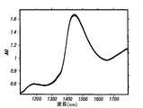
図1は、脂肪を連結させずに削り取った皮膚101、純粋なコラーゲン102、および、牛脂肪103のスペクトル特性のプロットを示している。処理された二次導関数が、脂肪およびコラーゲンの寄与を、主としてコラーゲンと水とから成る、削り取った皮膚と比較するために、用いられている。 FIG. 1 shows a plot of the spectral characteristics of
光と人間の皮膚との間の相互作用
光ビームが、皮膚表面上に向けられると、その一部が反射される一方、残りの部分が、皮膚に侵入する。反射光エネルギーの比率は、入射角に強く依存する。ほぼ垂直な入射においては、入射ビームの約4%が、空気(
皮膚に入ってきた入射ビームの93〜96 %は、皮膚のいずれかの層内での吸収または散乱によって減衰する。それら2つのプロセスが、総合して、皮膚への光の侵入、および、皮膚からの散乱光のレミッタンスを本質的に決定する。拡散反射、即ち、レミッタンスは、入射した光放射のうちの、不透明なサンプルから戻される部分として定義される。上述の様々な皮膚構成成分による吸収は、各層内におけるビームのスペクトル吸光の原因になる。散乱は、皮膚による拡散反射に寄与するようにビームを戻すことができる、唯一のプロセスである。散乱は、媒質を構成する小片の物理的特性の差に対応する、媒質の屈折率の差に起因する。散乱光の空間的な分布および強度は、波長に比しての小片のサイズおよび形状、および、媒質と構成成分の小片との間の屈折率の差に依存する。 93-96% of the incident beam that enters the skin is attenuated by absorption or scattering within any layer of the skin. Together, these two processes essentially determine the penetration of light into the skin and the remittance of scattered light from the skin. Diffuse reflection, or remittance, is defined as the portion of incident light radiation returned from an opaque sample. Absorption by the various skin components described above causes spectral absorption of the beam within each layer. Scattering is the only process that can return the beam to contribute to diffuse reflection by the skin. Scattering results from the difference in the refractive index of the medium, which corresponds to the difference in the physical properties of the small pieces that make up the medium. The spatial distribution and intensity of the scattered light depends on the size and shape of the pieces relative to the wavelength and the difference in refractive index between the medium and the constituent pieces.
生体組織の散乱係数は、間質液の濃度、構造繊維(structural fibers)の密度、および、細胞構造の形状およびサイズを含む、多くの制御し難い要因に依存する。コラーゲン繊維による散乱は、真皮内への光放射の侵入を決定する主要な重要事項である。非特許文献31を参照されたい。媒質の拡散能が、大きければ大きいほど、多重内部反射に関係する吸収が、より大きくなる。したがって、同じ人間の異なる部位、または、異なる人間の同じ部位から測定された反射率値は、ターゲット吸収体が、同じ濃度に存在するときでさえ、相当に異なることがある。これらの差は、性別、年令、遺伝、疾患、および、ライフスタイル差による外生要因に起因すると考えることができる。例えば、人間の皮膚の厚さは、女性よりも男性において、より厚く、一方、皮下脂肪の厚さは、女性において、より厚いことが知られている。同じグループが、真皮におけるコラーゲン密度、フィブリルの充填が、女性よりも男性の前腕において、より高いと報告している。非特許文献32を参照されたい。 The scattering coefficient of biological tissue depends on many uncontrollable factors, including the concentration of interstitial fluid, the density of structural fibers, and the shape and size of cellular structures. Scattering by collagen fibers is a key factor that determines the penetration of light radiation into the dermis. See Non-Patent Document 31. The greater the diffusivity of the medium, the greater the absorption associated with multiple internal reflections. Thus, the reflectance values measured from different parts of the same person, or from the same part of different persons, can be quite different even when the target absorber is present at the same concentration. These differences can be attributed to exogenous factors due to gender, age, heredity, disease, and lifestyle differences. For example, it is known that the thickness of human skin is thicker in men than in women, while the thickness of subcutaneous fat is thicker in women. The same group reports that collagen density in the dermis, fibril filling is higher in male forearms than in women. See Non-Patent Document 32.
皮膚の動的性質
皮膚の性質の知識および利用、高い機器感度、および、固有の非線形に対する補償は、非侵襲的組織分析対象物質測定への非侵襲的技術の応用にとって、極めて重要であるが、皮膚組織の性質に時間依存変化を導く生体的および化学的なメカニズムについての理解も、同様に、重要でありながら、大部分、無視されている。与えられた測定部位において、皮膚組織は、しばしば、ターゲット分析対象物質、および、他の干渉(妨害)種の変化を除いて、静的であると仮定される。しかしながら、組織の生理状態および液分布の変動は、相対的に短期間で、組織層および組織区分の光学的性質に深い影響を与える。そのような変動は、しばしば、水分移動を通しての液区分均一化によって支配され、水和レベル、および、血中分析対象物質レベルの変化に関係する。Skin dynamics Knowledge and use of skin properties, high instrument sensitivity, and compensation for inherent non-linearities are crucial for the application of non-invasive techniques to non-invasive tissue analyte measurements, The understanding of biological and chemical mechanisms that lead to time-dependent changes in the properties of skin tissue is equally important but largely ignored. At a given measurement site, skin tissue is often assumed to be static, except for changes in target analytes and other interfering species. However, changes in tissue physiology and fluid distribution have a profound effect on the optical properties of tissue layers and sections in a relatively short period of time. Such fluctuations are often dominated by liquid compartment homogenization through water movement and are related to changes in hydration levels and analyte levels in the blood.
総体内水は、平均的な人間の重量の60%を超える割合を占めて、2つの主な区分:細胞内液(総体内水の3分の2)と細胞外液(総体内水の3分の1)との間に分布する。非特許文献33を参照されたい。細胞外液は、次に、間質液(血管外)と血漿(血管内)とに分割される。透水性脂質膜が、区画を分離し、そして、その膜を通して、水および他の分析対象物質の濃度を均一化するために、水が、拡散プロセスを通じて、それらの区画の間に急速に送られる。1つの区画から別の区画への正味の水の流れが、浸透プロセスを構成し、また、浸透を防ぐのに必要な圧力の大きさが、浸透圧と名付けられる。静的な生理状態の下では、液区画は、平衡している。しかしながら、水の摂取または損失の結果としての正味の液の獲得または損失中に、全ての区画が、それに比例して、水を獲得または損失して、一定の相対容積を維持する。 Total body water accounts for more than 60% of the average human weight, and is divided into two main categories: intracellular fluid (2/3 total body water) and extracellular fluid (3 total body water). It is distributed between 1 and 1). See Non-Patent Document 33. The extracellular fluid is then divided into interstitial fluid (extravascular) and plasma (intravascular). A permeable lipid membrane separates the compartments and through the membrane, water is rapidly sent between the compartments through a diffusion process to homogenize the concentration of water and other analytes. . The net water flow from one compartment to another constitutes the osmosis process, and the amount of pressure necessary to prevent infiltration is termed osmotic pressure. Under static physiological conditions, the fluid compartment is balanced. However, during the gain or loss of net fluid as a result of water intake or loss, all compartments gain or lose water proportionally to maintain a constant relative volume.
組織によって必要とされる血清に含まれる物質、例えば、水およびブドウ糖を分配するための重要なメカニズムは、拡散プロセスを通じてである。Fickの拡散法則が、短期間で血管内/血管外液区画を平衡させることを理解することができる。血管内区画から血管外区画への水、および、他の分析対象物質の移動は、水、および、ブドウ糖を含む他の構成成分の分子が、一定の熱運動において、毛細血管壁を通ってあちこちに拡散するから、急速に生じる。平均して、水分子が、毛細血管膜を通して拡散する速度は、血漿自身が、毛細血管に沿って直線的に流れる速度よりも約80倍高い。Fickの法則の表現では、実際の拡散流IOAは、次式にしたがって、2つの区画の間の濃度勾配
血中ブドウ糖濃度の短期間の増加(または減少)は、血液のオスモル濃度(水の単位質量当りの分子の数)の増加(または減少)に導く。したがって、液は、急速に再分布して、各身体区画の水濃度の変化に帰着する。高血糖の場合には、浸透効果が、血管外の水を、ブドウ糖濃度が相対的に高い血管内スペース区画に移動させる。同時に、ブドウ糖が、2つの区画のオスモル濃度を平衡させるために、血管内スペースから血管外区画に輸送される。これと反対に、血中ブドウ糖濃度の減少は、ブドウ糖を、血管外スペースから血管内スペースに移動させるとともに、水を、血管内区画から血管外スペースに移動させる。
A short-term increase (or decrease) in blood glucose concentration leads to an increase (or decrease) in blood osmolality (number of molecules per unit mass of water). Thus, the fluid redistributes rapidly, resulting in changes in the water concentration of each body compartment. In the case of hyperglycemia, the osmotic effect moves extravascular water to the intravascular space compartment where the glucose concentration is relatively high. At the same time, glucose is transported from the intravascular space to the extravascular compartment to balance the osmolality of the two compartments. In contrast, a decrease in blood glucose concentration moves glucose from the extravascular space to the intravascular space and moves water from the intravascular compartment to the extravascular space.
細胞膜は、ほとんどの溶質を、相対的に通さない(浸透させない)が、水を高度に通すから、細胞膜の片側に、相対的に高い濃度の溶質が存在するときには常に、水が、その膜を横切って、相対的に高い溶質濃度の領域に拡散する。大きな浸透圧が、細胞外液の溶質濃度の比較的小さな変化によって、細胞膜を横切って発現することができる。その結果、ブドウ糖のような、細胞外液中の非透過性の溶質の濃度の比較的小さな変化が、細胞容積に、非常に大きな変化を引き起こすことができる。 The cell membrane is relatively impermeable to (permeate) most solutes, but is highly permeable to water, so whenever there is a relatively high concentration of solute on one side of the cell membrane, the water will penetrate the membrane. Across and diffuse into areas of relatively high solute concentration. A large osmotic pressure can be developed across the cell membrane by relatively small changes in the extracellular fluid solute concentration. As a result, relatively small changes in the concentration of impermeable solutes in the extracellular fluid, such as glucose, can cause very large changes in cell volume.
サンプリング誤差
血中ブドウ糖濃度のような、組織の性質および分析対象物質の非侵襲的測定に、NIR分光法を使用することができる。上述の特許文献1は、NIR分光分析を用いて、インビボで血中ブドウ糖濃度を非侵襲的に予測するためのシステムについて記述している。そのようなNIR分光に基づく方法は、同じ組織容積の、インビボに反復される光学的サンプルを用いて展開されるキャリブレーションを利用する。それらの連続する測定は、使用可能なキャリブレーションを生み出すために、十分に反復性の高いスペクトルを与えなければならない。本明細書に記述されているように、生きている人間の皮膚の種々雑多で動的な特質は、インビボ測定において、サンプリングを不確実にする。組織の変動しやすい化学的組成および光散乱性質は、サンプリング差を発生させることができる。一例として:ブドウ糖は、組織内に一様に分布していないから、たとえ、組織中または血液中のブドウ糖濃度が、一定のままでも、サンプルされた組織容積の変動は、ブドウ糖信号強度の変動に導くであろう。測定表面部位においてサンプルするために用いられる光学的プローブを反復して設置する際の変動は、2つの別々の仕方で、サンプリング誤差に導くことができる。第一に、プローブの場所の変動は、異なる組織容積をサンプルさせることができ、そして、第二に、プローブによって組織に加えられる圧力の大きさの変動は、組織による光学的散乱を変え、それによって、サンプルされる組織容積を変化させることができる。光学的サンプリングの変化は、たとえ、血液中または組織中のターゲット分析対象物質の濃度が変化しないままであっても、そのターゲット分析対象物質のスペクトル信号を変動させることがある。さらに、光学的プローブの表面と、サンプルされる組織の表面との間のエア・ギャップは、変動しやすい表面反射を起こす。変動しやすい表面反射は、組織への変動しやすい光進入に導き、それは、次に、スペクトル測定の非線形特質の増大を起こす。変動しやすい非線形測定をキャリブレートすることが非常に困難であるのは確かである。NIR spectroscopy can be used for non-invasive measurements of tissue properties and analytes, such assampling error blood glucose concentration. The above-mentioned
光学的プローブをガイドして、結合するための種々のシステムが、知られている。例えば、特許文献2および特許文献3は、ともに、光ファイバのケーブルまたは細線が縦方向に通されるフェルールを利用する光ファイバ・プローブ・ガイドを開示している。両デバイスとも、光ファイバケーブルまたは細線を、医療機器の種々の形状のレセプタクル、または、他の光ファイバのケーブルに結合するコネクタである。どちらのデバイスも、光ファイバ・プローブを、組織測定部位に反復可能に結合するための手段を備えていない。 Various systems are known for guiding and coupling optical probes. For example,
特許文献4は、手術プロセスまたは診断プロセス中に、心臓マッピングおよびアブレーション・プローブを、心室にガイドするカテーテルおよびガイド・シースを使用するシステムについて記述している。特許文献4の教示は、心臓の手術方法に向けられており、インビボでの組織の光学的サンプリングと全く関係がない。さらに、特許文献4の装置は、光学的プローブを、組織測定部位に反復可能に結合するのに適していない。 U.S. Patent No. 6,057,034 describes a system that uses a catheter and guide sheath to guide a cardiac mapping and ablation probe into the ventricle during a surgical or diagnostic process. The teachings of U.S. Patent No. 6,057,059 are directed to cardiac surgery methods and have nothing to do with optical sampling of tissue in vivo. Furthermore, the device of
特許文献5は、アセンブリ・プロセス中に2つの成分をアラインさせるための、レーザのような照射デバイスを用いる方法について記述している。特許文献5の教示は、インビボでの組織の光学的サンプリングではなくて、製造プロセスに向けられている。特許文献5のデバイスは、プローブ・ガイドを、組織測定部位に反復可能に設置するための如何なる手段も備えていない。それは、さらに、組織測定部位の表面温度をモニタする方策も、組織測定部位の表面温度のばらつき、および、水分の蓄積を最小化する方策も持たない。 U.S. Patent No. 6,057,032 describes a method of using an irradiation device such as a laser to align two components during the assembly process. The teaching of U.S. Patent No. 6,057,059 is directed to the manufacturing process, not optical sampling of tissue in vivo. The device of Patent Document 5 does not include any means for repeatedly installing the probe guide at the tissue measurement site. It further has no strategy to monitor the surface temperature of the tissue measurement site nor to minimize the variation in surface temperature of the tissue measurement site and the accumulation of moisture.
特許文献6は、光ファイバを、望みの角度位置に位置決めするために、フレームに結合される光ファイバ支持物を開示している。前述の従来技術の場合と同様に、特許文献6の教示は、インビボでの組織の光学的サンプリングと全く関係がない。さらに、開示されているデバイスは、オペレータが、光ファイバを、それが固定位置に維持されるように動けなくすることを可能にするが、光ファイバ・プローブを、組織測定部位に反復可能に結合する手段を提示しない。それは、また、組織測定部位の表面温度をモニタする方策も、その部位における、蓄積される水分および温度のばらつきを最小化する方策も持たない。 Patent Document 6 discloses an optical fiber support that is coupled to a frame in order to position an optical fiber at a desired angular position. As with the prior art described above, the teachings of US Pat. In addition, the disclosed device allows the operator to immobilize the optical fiber so that it remains in a fixed position, but repeatably couples the optical fiber probe to the tissue measurement site. It does not present a means to do. It also has no way to monitor the surface temperature of the tissue measurement site nor to minimize the accumulated moisture and temperature variations at that site.
特許文献7は、分光分析中、センサ・プローブと皮膚表面との間のインターフェイスを改善するための屈折率整合媒質を開示している。特許文献7は、ペルフルオロカーボンとクロロフルオロカーボンとを含む媒質を教示している。それらは、有名な発癌物質であるから、クロロフルオロカーボン(CFC)は、生きている組織に用いられる調合剤に用いるのには不適当である。さらに、CFCの使用は、周知の環境上の危険をもたらす。それに加えて、特許文献7のインターフェイス媒質は、分光測定中に人工産物を残すと思われる物質で処方されている。 U.S. Patent No. 6,057,031 discloses a refractive index matching medium for improving the interface between a sensor probe and a skin surface during spectroscopic analysis. Patent Document 7 teaches a medium containing perfluorocarbon and chlorofluorocarbon. Because they are famous carcinogens, chlorofluorocarbons (CFCs) are unsuitable for use in pharmaceutical preparations used in living tissues. In addition, the use of CFC poses known environmental hazards. In addition, the interface medium of Patent Document 7 is formulated with a substance that is expected to leave an artifact during spectroscopic measurements.
したがって、当業技術には、組織分析対象物質を測定するための非侵襲的キャリブレーションの展開に必要な、正確な光学的サンプリングを達成する手段の必要性が存在する。非侵襲的測定中に光学的サンプリングを制御する問題の解決のためには、生きている組織、とりわけ、皮膚の構造特性および動的性質によってもたらされる、以下のいくつかの難問に取り組む必要がある。 Accordingly, there is a need in the art for a means to achieve the precise optical sampling required for the development of non-invasive calibration for measuring tissue analytes. Solving the problem of controlling optical sampling during non-invasive measurements requires addressing some of the following challenges posed by the structural and dynamic properties of living tissue, especially skin .
・ 表面組織の表面結合と表面伸張における光学収差による表面反射を制御すること。
・ 不正確な設置による、サンプルされる組織容積の変動、および、サンプリング容積を不確かにする、真皮コラーゲンの変動しやすい伸張を制御すること。
・ 器械または設置ガイドから測定部位の周辺のエリアにかかる圧力に起因する、組織内の水のたまりに関連する測定偏りを補正すること。
・ 表面組織の水和を安定化させること。Control surface reflections due to optical aberrations in surface bonding and surface stretching of surface tissues.
Control the variation of the sampled tissue volume due to inaccurate placement and the variable stretch of dermal collagen that makes the sampling volume uncertain.
• Correct measurement bias related to water pools in the tissue due to pressure applied from the instrument or installation guide to the area around the measurement site.
・ Stabilize the hydration of the surface tissue.
組織のインビボ光学的サンプリングのために、組織測定部位に光学的プローブを結合する、光学的プローブのための設置ガイドを備えることが望ましい。さらに、同じ組織サンプル容積を、反復可能にサンプルすることができることを確実にし、それによって、機械的な組織の歪みおよびプローブ設置によるサンプリング誤差を排除する手段を備えることが望ましい。さらに、組織測定部位における温度のばらつきを最小化し、また、角質層の含水量を安定化する方策を備えて、それによって、さらなるサンプリング誤差源を排除することが望ましい。さらに、光学的プローブと、組織測定部位の皮膚との間に、無毒で、無刺激性であって、分光測定に誤差を導入しない一定のインターフェイスを備えるために、光学的結合媒質を備えることも非常に有利である。それに加えて、組織測定部位の表面温度をモニタする手段を備えて、その結果、温度が、反復される光学的サンプルの全部にわたって一定のままであることを確実にすることも有利である。最後に、設置ガイドを測定部位に取り付けるために用いられる機械的な取り付けプロセスに内在する不確実さに起因する組織サンプリングの偏りを補正するための手段を備えることも有利である。 For in vivo optical sampling of tissue, it is desirable to provide an installation guide for the optical probe that couples the optical probe to the tissue measurement site. Furthermore, it would be desirable to have means to ensure that the same tissue sample volume can be sampled repeatably, thereby eliminating sampling errors due to mechanical tissue distortion and probe placement. Furthermore, it is desirable to have a strategy to minimize temperature variations at the tissue measurement site and to stabilize the moisture content of the stratum corneum, thereby eliminating additional sampling error sources. In addition, an optical coupling medium may be provided to provide a constant interface between the optical probe and the skin at the tissue measurement site that is non-toxic, non-irritating and does not introduce errors into the spectroscopic measurement. Very advantageous. In addition, it is advantageous to provide means for monitoring the surface temperature of the tissue measurement site, so that the temperature remains constant throughout the repeated optical sample. Finally, it is also advantageous to provide means for correcting tissue sampling bias due to the uncertainty inherent in the mechanical attachment process used to attach the installation guide to the measurement site.
本発明は、分光手段による光学的組織サンプリング中、および、その後の分析対象物質測定中の測定部位におけるサンプリング変動および/または状態のばらつきに起因する誤差を最小化し、そして、補償する光学的サンプリング・インターフェイス・システムを提供する。 The present invention minimizes and compensates for errors due to sampling variations and / or state variations at the measurement site during optical tissue sampling by spectroscopic means and during subsequent analyte measurements. Provide an interface system.
光学的プローブ設置ガイドが、最小で反復可能な程度の組織の歪みおよび変位しか持たない、組織測定部位の表面の反復可能な場所精度を容易にする。そのプローブ設置ガイドの主要な構造成分は、使用中に光学的プローブを受け取る開口を持つマウントである。複数の測定の間で、プローブ設置精度を改善することに加えて、ガイド開口は、ガイド接着表面と、ガイドのいずれの部分も組織と接触しないガイド開口とにおける接触圧力の相対差のためにガイド開口内の表皮に水がたまることによって生成される組織メニスカス(組織の半月状のふくらみ)の形成を誘起する。組織メニスカスの形成は、表面の凹凸による干渉を最小化し、また、サンプルされる組織容積の変動を制御する。 The optical probe placement guide facilitates repeatable location accuracy of the surface of the tissue measurement site with minimal and repeatable tissue distortion and displacement. The main structural component of the probe installation guide is a mount with an opening that receives the optical probe during use. In addition to improving probe placement accuracy among multiple measurements, the guide opening guides due to the relative difference in contact pressure between the guide adhesive surface and the guide opening where no part of the guide contacts the tissue. It induces the formation of a tissue meniscus (a semi-moon-shaped bulge of tissue) generated by the accumulation of water in the epidermis within the opening. The formation of the tissue meniscus minimizes interference due to surface irregularities and controls variations in the sampled tissue volume.
組織メニスカス上に設置された閉塞要素が、周囲のばらつきから組織メニスカスを隔離し、したがって、組織メニスカスの水和の程度を安定化させ、それによって、組織メニスカスの表面張力を安定化させる。組織測定部位の表面組織上に置かれた光学的結合媒質が、皮膚表面と光学的プローブとの間のエア・ギャップによるサンプリング誤差を排除する。 An occlusive element placed on the tissue meniscus isolates the tissue meniscus from ambient variations and thus stabilizes the degree of tissue meniscus hydration, thereby stabilizing the surface tension of the tissue meniscus. An optical coupling medium placed on the surface tissue of the tissue measurement site eliminates sampling errors due to an air gap between the skin surface and the optical probe.
測定および偏り補正要素が、スペクトル測定、および、それに連結する分析対象物質測定に、偏り補正を適用する。そのような偏り補正は、一ガイド設置中に取り入れられる全てのデータに対して、全く同じに行なわれる。ガイドが、取り除かれて、置き替えられると、新しい偏り補正が、第2のガイド設置で取り入れられる、その後の全てのデータに対して量定される。 The measurement and bias correction element applies bias correction to the spectrum measurement and the analyte measurement linked thereto. Such bias correction is performed in exactly the same way for all data taken during the installation of one guide. When the guide is removed and replaced, a new bias correction is quantified for all subsequent data taken in the second guide installation.
それに加えて、本発明のシステムの個々の要素の各々は、種々の測定誤差源を阻止するための独立した解決策として、個々に、展開することができる。したがって、プローブ設置ガイドは、システムの他の要素と独立に、サンプリング誤差に十分の減少をもたらす。閉塞要素は、測定部位の表面の状態のばらつきによる測定誤差に十分の減少をもたらす。そして、補正アルゴリズムを、システムの他の要素を欠くセッティングにおいて、スペクトル測定に適用することができる。 In addition, each of the individual elements of the system of the present invention can be individually deployed as an independent solution to block various measurement error sources. Thus, the probe installation guide provides a sufficient reduction in sampling error, independent of other elements of the system. The occlusion element provides a sufficient reduction in measurement error due to variations in the surface condition of the measurement site. The correction algorithm can then be applied to spectral measurements in settings that lack other elements of the system.
生きている組織の分光分析において、光学的プローブを用いて、同じ組織容積を、光学的に反復してサンプルすることが、しばしば、必要である(例えば、1つ以上の組織分析対象物質を測定するための非侵襲的キャリブレーションを展開する間、そして、その後、実際の分析対象物質測定のための測定を行うとき)。光学的プローブを、前の測定に用いられた、その正確な場所に反復して設置する困難さのために、および、同じほんのわずかの程度の組織の歪みおよび変位しか、反復可能に、生み出さないことの難しさのために、サンプリング誤差が、それらの測定において導入されうる。反復されるプローブ接触事象に起因するプローブの場所の各小さな変動、または、圧力量の変動によって、わずかに異なる組織容積が、サンプルされ、それによって、サンプリング誤差が、それらの測定に導入される。本発明は、サンプリング誤差の原因となる要因を排除する、または、最小化する光学的サンプリング・インターフェイス・システムを提供する。 In spectroscopic analysis of living tissue, it is often necessary to optically and repeatedly sample the same tissue volume using an optical probe (eg, measuring one or more tissue analytes). During the non-invasive calibration to develop and then when performing measurements for actual analyte measurements). Due to the difficulty of repeatedly placing the optical probe in its exact location used for previous measurements, and only the same minor degree of tissue distortion and displacement is produced repeatably. Because of this difficulty, sampling errors can be introduced in these measurements. With each small variation in probe location due to repeated probe contact events, or a variation in the amount of pressure, a slightly different tissue volume is sampled, thereby introducing a sampling error into those measurements. The present invention provides an optical sampling interface system that eliminates or minimizes factors that cause sampling errors.
プローブ設置ガイド
ターゲット組織測定部位に高度に反復可能にプローブを設置する目標を達成するために、組織部位に取り除き可能に取り付けられる光学的プローブ設置ガイドの使用を通して、ターゲット組織容積の優れたサンプリング精度を備えたシステムが、本明細書において記述される。そのガイドの主要な特性は、特定の組織容積が、光学系によって正確にサンプルされるように、そのガイドが、光学的プローブに関して、ターゲット組織容積の場所を位置合わせするための手段を備えているということである。位置合わせとは、組織上のターゲット場所に関する、光学的プローブの位置についてのフィード・バックを供給することを指す。ガイドと光学的プローブとの間の位置合わせ手段は、機械的でも、光学的でも、電気的でも、磁気的でもよい。それに加えて、ガイドは、光学的プローブを受け取る開口を含んでいる。その開口は、次のものを含む、いくつかの目的に役立つ。Probe installation guide To achieve the goal of highly repeatableprobe installation at the target tissue measurement site, through the use of an optical probe installation guide that is removably attached to the tissue site, it provides excellent sampling accuracy of the target tissue volume A system with which is provided is described herein. The main property of the guide is that the guide comprises means for aligning the location of the target tissue volume with respect to the optical probe so that the specific tissue volume is accurately sampled by the optical system. That's what it means. Alignment refers to providing feedback on the position of the optical probe with respect to the target location on the tissue. The alignment means between the guide and the optical probe may be mechanical, optical, electrical or magnetic. In addition, the guide includes an opening that receives the optical probe. The opening serves several purposes, including:
・ 機械的な位置合わせ点。
・ 安定した組織メニスカスを生成するための手段。
・ 測定部位の組織の表面状態が、測定の合間に安定化できるように、閉塞プラグを受け取るための開口部。• Mechanical alignment points.
-Means for generating a stable tissue meniscus.
An opening for receiving an occlusive plug so that the surface condition of the tissue at the measurement site can be stabilized between measurements.
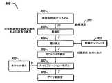
図2に示される好適な一実施例において、ガイド200は、楕円形であり、サンプルされる組織部位の表面、例えば、前腕の手のひら(たなごころに相当する)側の表面または背側の表面、に近似するように、その輪郭がつけられている。しかしながら、他の形状が、手、耳たぶ、脚、腹、上腕領域、および、手指のような身体の他の場所に対しては、用いられる。ガイドの設計は、サンプルされる組織部位に、大きな機械的エネルギーを加えることのない、快適で目立たない使用を可能にするように意図される。現実施例においては、ガイドは、硬質ポリマからできており、安定した組織メニスカスの生成を可能にする。しかしながら、軽金属のような、剛性と軽量との必要な組合せを備えた他の物質も、好適である。 In one preferred embodiment shown in FIG. 2, the
組織部位へのガイドの取り付けは、ガイド200の接触面上の接着層201によってもよい。接着層は、製造時に塗ってもよいし、使用に先立ってガイドに塗ってもよい。一般に、接着剤が、ガイドの全接触面、即ち、組織測定部位に隣接して、それを囲んでいる皮膚エリアに接するガイドのその表面をカバーしている。それに加えて、ストラップ、吸着、または、腕バンドのような、他の取り付け手段も、好適である。ガイドは、測定期間の初めに、組織部位に取り付けられる。通常、この期間は、前に用いられたガイドが取り除かれてしまった後の特定の日の始めである。好適な一実施例において、取り付け方法は、接着層を、適所に塗って、むき出しにして、非侵襲的測定デバイス上に、ガイド200を設置することである。その後、組織測定部位が、腕受け台、または、ひじおよび手首支持体によって粗く位置合わせされて、ガイド上に設置される。この第1の設置中に、ガイドは、組織部位に貼られるようになる。 Attachment of the guide to the tissue site may be by an adhesive layer 201 on the contact surface of the
ガイド200は、機器から腕に送られる機械的エネルギーを、測定部位のまわりの、より大きなエリアにわたって分散させる。しかしながら、変形または移動を受けやすい身体の部分を伴う適用においては、ガイドは、測定部位の安定化、および、ターゲット組織容積に過度の力を印加することなく、下層組織の変形をもたらす、可塑性ポリマのような、可塑性材料から成ってもよい。
ガイドは、光学的プローブを受け取る開口202を持っている。光学的プローブとガイド開口202とのサイズおよび形状は、光学的プローブが、ガイドによって受け取られるとき、それが、ぴったりと嵌合して、組織測定部位に関して、x-y平面で機械的な位置合わせがもたらされるように、互いに適合している。組織への光学的プローブの過剰な侵入を回避し、光学的プローブと組織との間に反復可能な圧力を促進するために、ガイドおよび光学的プローブは、組織への光学的プローブの侵入(z方向)を制限して、制御する機械的ストップ203を備えている。組織の重量が、機械的ストップ203を通して光学的プローブに送られ、それによって、組織測定部位における圧力が、減少する。 The guide has an
ガイドは、任意選択の温度プローブ挿入のためのスロット208を備えている。この形態は、皮膚温度のモニタのためのキャリブレーション段階中に、特に、有用である。 The guide includes a
測定部位の閉塞
組織部位が、光学的プローブにインターフェイスしていないとき、閉塞プラグ204が、通常、開口202に挿入される。閉塞プラグは、光学的プローブと同じ程度まで開口に侵入し、その結果、光学的プローブの接触エネルギーを模造することによって、安定した組織状態を生成する。前に検討したように、閉塞プラグは、水和バリアをもたらす物質からできており、それによって、角質層の十分で安定した水和を促進する。好適な一実施例において、このプラグは、ガイドと同じ物質からできており、また、組織部位への侵入を制御するための機械的なストップ205を持っている。開口内に挿入されるプラグの部分206のサイズは、ガイド開口202によって受け取られる光学的プローブの部分に合致する。ガイドへのプラグの取り付けは、ガイド・アセンブリとプラグ・アセンブリとの両方に据えられた1つ以上の磁石207の使用によってもよい。しかしながら、VELCRO(マジックテープ)、接着剤、および、スナップのような、他の取り付け方法を、用いてもよい。それに代えて、プラグを、弾性的な性質の物質から構成して、それを、ガイド開口に、きつく嵌合させることによって、適所に維持させてもよい。さらに、プラグは、セロファンのような疎水性の物質であってもよい。An
前述のことから、当業者であれば誰でも、本光学的サンプリング・システムの1つの重要な態様は、光学的信号の増大、サンプル再現性、および、表面反射の抑制のために、測定部位の表面組織の水和の最適レベルを維持することであることを認識するであろう。前述のように、水和メカニズムの好適な一実施例は、経皮水分蒸散(TEWL)の閉塞ブロッケージによるものである。このブロッケージは、内部組織から拡散してくる水を角質層に閉じ込めるから、定常状態の水和を確実にする。高い水和レベルの達成は、この経皮水分蒸散に推進力を与える水濃度勾配を減少させる。したがって、上述の閉塞プラグは、測定の合間の期間中、ガイド開口にぴったりと嵌合して、ガイド開口内の組織を、経皮水分蒸散、および、角質層の水和状態に影響を及ぼすことが知られている温度および湿度の環境効果から隔離するように作用する。この記述したばかりの好適な一実施例に加えて、代替の一実施例において、測定部位のまわりを、可塑性ポリマ・シート(閉塞パッチ)で包んだ状態を用いて、閉塞によって高度に水和された状態を達成してもよい。 From the foregoing, anyone of ordinary skill in the art will appreciate that one important aspect of the present optical sampling system is the measurement site for increased optical signal, sample reproducibility, and suppression of surface reflections. It will be appreciated that maintaining an optimum level of surface tissue hydration. As mentioned above, one preferred embodiment of the hydration mechanism is by occlusive blockage of transdermal water transpiration (TEWL). This blockage ensures steady-state hydration because it confines water diffusing from internal tissues in the stratum corneum. Achieving high hydration levels reduces the water concentration gradient that provides driving force for this transdermal moisture transpiration. Thus, the occlusion plug described above fits snugly into the guide opening during the interval between measurements, affecting the tissue in the guide opening to transdermal moisture transpiration and the hydration state of the stratum corneum. Acts to isolate it from known environmental effects of temperature and humidity. In addition to this preferred embodiment just described, in an alternative embodiment, the measurement site is highly hydrated by occlusion using a state wrapped with a plastic polymer sheet (occlusive patch). May be achieved.
本発明の精神および範囲と一致する、角質層の水和を維持する問題に対する他の解決法は、以下のものを含めて可能であるが、それらに限定されることはない。 Other solutions to the problem of maintaining stratum corneum hydration consistent with the spirit and scope of the present invention are possible, including but not limited to the following.
・ 測定のためのターゲット部位をカバーするように構成されたラップまたはパッチの形状の防湿材または半透膜(例えば、切手アルバムの透明なポケットとして、W. L. Gore and Associates(ニューアーク、デラウェア州)によって製造されたGORE-TEX)。この最後の実施例において、「パッチ」が、接着剤、または、ストラップまたはラップのような他の取り付けメカニズムによって、組織部位に貼り付けられる。
・ 角質層の水和のための非閉塞メカニズムを、以下のものを含んで、さらに、用いてもよい。
・ 空気圧によって、皮膚に送り込まれる水の印加。
・ 外的作用によって生じる閉塞(passive occlusion)を加速する超音波エネルギーの印加。
・ 乾燥した外部皮膚層に、水および溶質を送り込むのに役立つ化粧水、および、アルファ・ハイドロキシ酸溶液のような、他の水/溶質混合液の局部印加。
・ 表面の水和の改善に導く測定部位の局所的血行を高める、および/または、刺激する局部無痛性処方。• Moisture-proof or semi-permeable membrane in the form of a wrap or patch configured to cover the target site for measurement (eg by WL Gore and Associates (Newark, Delaware) as a transparent pocket on a stamp album) Manufactured GORE-TEX). In this last example, the “patch” is applied to the tissue site by an adhesive or other attachment mechanism such as a strap or wrap.
-Non-occlusion mechanisms for stratum corneum hydration may further be used, including:
・ Application of water sent to the skin by air pressure.
Application of ultrasonic energy to accelerate passive occlusion caused by external action.
• Local application of lotions to help pump water and solutes into the dry external skin layer and other water / solute mixtures such as alpha-hydroxy acid solutions.
A local painless prescription that enhances and / or stimulates local blood circulation at the measurement site leading to improved surface hydration.
角質層の水和を達成するためのメカニズムを、処理を結合して用いてもよい。例えば、化粧水溶液、または、超音波エネルギー印加を、閉塞プラグと組み合わせて用いてもよい。 A mechanism for achieving stratum corneum hydration may be used in conjunction with the treatment. For example, a cosmetic aqueous solution or ultrasonic energy application may be used in combination with an occlusive plug.
初期測定が、なされた後、上述のように、その後の測定が、単純に、組織部位を、非侵襲的測定デバイス上に置き(閉塞プラグを除去した後で)、ガイドが機械的な位置合わせをするにまかせることによって、なされる。光学的組織測定が、行なわれた後、組織が、デバイスから取り去られ、閉塞プラグが、再挿入される。 After the initial measurement is made, as described above, subsequent measurements simply place the tissue site on the non-invasive measurement device (after removing the occlusion plug) and the guide is mechanically aligned. It is done by letting you do it. After the optical tissue measurement is performed, the tissue is removed from the device and the occlusion plug is reinserted.
光学的位置合わせ
代替の一実施例において、ガイドは、光学的位置合わせのための手段を備えている。この実施例においては、反射体、または、受光素子が、ガイド上に設置される。その光学的プローブアセンブリは、ガイドの位置を、二次元または三次元のいずれかで、正確に算定することを可能にする光源、および、いくつかの検出器を備えている。第1の構成においては、二次元(x, y)が、算定され、また、機械的ストップが、第3の次元を制御するために用いられる。第2の構成においては、ガイドの場所が、三次元(x, y, z)全てにおいて、光学的に算定される。ガイドの位置は、ターゲット組織容積に関して一定であるから、その位置算定は、光学的プローブに関して、ターゲット組織容積の場所に関する正確な情報を供給する。そのような算定によって供給される位置合わせ情報が、以下の手段のいずれかを通して、組織部位を、光学的プローブ上に置くために、または、その逆のために用いられる。In one embodiment of theoptical alignment alternative, the guide comprises means for optical alignment. In this embodiment, a reflector or a light receiving element is installed on the guide. The optical probe assembly includes a light source and several detectors that allow the position of the guide to be accurately calculated in either two or three dimensions. In the first configuration, two dimensions (x, y) are calculated and a mechanical stop is used to control the third dimension. In the second configuration, the location of the guide is optically calculated in all three dimensions (x, y, z). Since the position of the guide is constant with respect to the target tissue volume, its position calculation provides accurate information regarding the location of the target tissue volume with respect to the optical probe. The alignment information provided by such calculations is used to place the tissue site on the optical probe or vice versa through any of the following means.
・ オペレータまたはユーザが、どのように、光学的プローブに関して、組織部位を移動させるかを示す、視覚的または聴覚的な信号が与えられる。
・ 機械的な位置決めシステムが、光学的プローブに関して、組織測定部位を位置決めするために用いられる。
・ 機械的な位置決めシステムが、組織測定部位上に、光学的プローブを位置決めするために用いられる。A visual or audible signal is provided that indicates how the operator or user moves the tissue site with respect to the optical probe.
A mechanical positioning system is used to position the tissue measurement site with respect to the optical probe.
A mechanical positioning system is used to position the optical probe on the tissue measurement site.
当業者であれば、組織測定部位に関して、ガイドの場所を算定するために、磁気検知システムも容易に応用することができることを認識するであろう。 One skilled in the art will recognize that a magnetic sensing system can also be readily applied to determine the location of the guide with respect to the tissue measurement site.
複数の測定間で、プローブ設置事象の精度を改善することに加えて、ガイド開口は、組織メニスカス、即ち、光学的プローブの開口中への組織の上向きのふくらみの形成を誘起する。組織メニスカス、即ち、ガイド接着表面とガイド開口とにおける接触圧力の相対的な差に起因するガイド開口中の皮膚表面下の水のたまりは、組織へのプローブの侵入の制限をもたらすのみならず、非常に迎合的で、エネルギーを吸収する接触事象を保証する。 In addition to improving the accuracy of the probe placement event between multiple measurements, the guide opening induces the formation of a tissue meniscus, ie, an upward bulge of tissue into the optical probe opening. A tissue meniscus, i.e., a puddle of water under the skin surface in the guide opening due to the relative difference in contact pressure between the guide adhesive surface and the guide opening, not only results in limited penetration of the probe into the tissue, It is very compliant and ensures energy absorbing contact events.
開口内の組織内部の静水圧は、むき出しの(ガイドのない)組織サンプルの静水圧よりも高い。この増加した静水圧は、プローブが組織に接触するときに、組織に送られるエネルギーを吸収し、それによって、真皮のコラーゲン組織に生じる歪みを制限する。真皮のコラーゲンの歪みは、組織の光学特性に、したがって、サンプルされる組織容積に強い効果を持つ。その補正を達成するために、光学的プローブの終端は、光学的プローブが完全に設置されたとき、組織測定部位の接触面の端とそろうべきである。 The hydrostatic pressure inside the tissue in the opening is higher than the hydrostatic pressure of the bare (unguided) tissue sample. This increased hydrostatic pressure absorbs the energy delivered to the tissue when the probe contacts the tissue, thereby limiting the strain that occurs in the collagen tissue of the dermis. The distortion of the dermal collagen has a strong effect on the optical properties of the tissue and thus on the sampled tissue volume. In order to achieve that correction, the end of the optical probe should be aligned with the end of the contact surface of the tissue measurement site when the optical probe is fully installed.
光学的結合媒質
光学的プローブと、組織測定部位の皮膚表面との間のインターフェイスも、重要なサンプリング誤差源となる場合がある。下層組織が、均一でないから、組織測定部位の表皮は、間隔の狭い凹凸を持って、平らでない。光学的プローブの相対的に滑らかな表面を、凹凸のある皮膚表面に結合させると、エア・ギャップが、それらの2つの表面の間に生じる。それらのエア・ギャップは、2つの表面間に、組織の光学的サンプリング中、測定に悪影響を与えるインターフェイスを生成する。図4に示されるように、光学的プローブ402と、組織測定部位400の皮膚との間の、光学的結合液401のような、ある量の光学的結合媒質が、そのようなギャップを解消する。The interface between the opticalcoupling medium optical probe and the skin surface of the tissue measurement site may also be an important source of sampling error. Since the underlying tissue is not uniform, the epidermis of the tissue measurement site is uneven with closely spaced irregularities. When the relatively smooth surface of the optical probe is bonded to an uneven skin surface, an air gap is created between those two surfaces. These air gaps create an interface between the two surfaces that adversely affects the measurement during optical sampling of tissue. As shown in FIG. 4, an amount of optical coupling medium, such as
光学的結合液は、以下のようであるのが好ましい。
・ スペクトル的に感度を持たない。
・ 無刺激かつ無毒である。
・ 良好な表面被覆性質を得るために、低粘性を持っている。
・ 反復適用における皮膚からの脂肪酸および油の浸出に関して、溶解力に乏しいという性質を持つ。The optical coupling liquid is preferably as follows.
・ There is no spectral sensitivity.
・ Non-irritating and non-toxic.
・ It has low viscosity to obtain good surface coating properties.
-It has the property of poor dissolving power with respect to the leaching of fatty acids and oils from the skin in repeated applications.
ペルフルオロカーボンと呼ばれる化合物、炭素原子とフッ素原子しか含まない化合物のクラスから、有効な光学的結合液の成分を選択することによって、そのような特性を達成することが可能である。鎖長を、20個未満の炭素に名目的に制限することによって、必要な粘性特性を持つ分子が、得られる。ペルフルオロカーボン結合液に含まれる分子種は、分枝鎖構造を含んでもよいし、直鎖構造を含んでもよい。多分散ペルフルオロカーボンとして結合液に含まれる、小さなペルフルオロカーボン分子の混合液は、製造コストを低く維持すると同時に、必要な特性を備えている。 Such properties can be achieved by selecting effective optical coupling fluid components from a class of compounds called perfluorocarbons, compounds containing only carbon and fluorine atoms. By limiting the chain length to nominally less than 20 carbons, molecules with the necessary viscosity properties are obtained. The molecular species contained in the perfluorocarbon binding liquid may include a branched chain structure or a linear structure. A mixture of small perfluorocarbon molecules contained in the binding liquid as a polydisperse perfluorocarbon has the necessary properties while maintaining low manufacturing costs.
好適な一実施例において、光学的結合液は、3M Corporationによって製造されているFC-40およびFC-70として知られているようなペルフルオロ化合物である。そのような化合物は、近赤外線領域において感度を持たず、そのことは、それらの化合物を、近赤外線スペクトルを使用する光学的サンプリング処理に、特別に非常に適したものとする。それに加えて、それらは、無毒かつ無刺激であるという長所を持っている。したがって、それらは、生きている被験者に重大な健康上の危険をもたらすことなく、長期間でも、生きている組織と直接接触することができる。さらに、このタイプのペルフルオロ化合物は、疎水性であり、かつ、溶解力に乏しい。したがって、それらは、光学的サンプリング中に、結果に悪影響を与える水、または、他の混入物質を吸収する見込みはない。光学的サンプリング液は、光学的サンプルに人工産物を導入するであろうアルコールまたは洗剤のような他の物質を加えることなく処方することが望ましい。最後に、ペルフルオロ化合物の並外れた安定性は、クロロフルオロカーボンに一般的に連結する環境上の危険を解消する。 In one preferred embodiment, the optical coupling liquid is a perfluoro compound such as known as FC-40 and FC-70 manufactured by 3M Corporation. Such compounds are not sensitive in the near-infrared region, which makes them particularly well suited for optical sampling processes using the near-infrared spectrum. In addition, they have the advantage of being non-toxic and non-irritating. Thus, they can be in direct contact with living tissue even for extended periods without incurring significant health risks to living subjects. Furthermore, this type of perfluoro compound is hydrophobic and has poor dissolving power. Thus, they are unlikely to absorb water or other contaminants that adversely affect the results during optical sampling. It is desirable to formulate the optical sampling liquid without adding other substances such as alcohol or detergents that would introduce artifacts into the optical sample. Finally, the extraordinary stability of perfluoro compounds eliminates the environmental hazards typically associated with chlorofluorocarbons.
さらに、ペルフルオロカーボンおよびクロロフルオロカーボンを含んでいる他の液組成も、光学的結合液として好適である。例えば、90%の高分子クロロトリフルオロエチレンと、10%の他のフルオロカーボンとの混合物は、望ましい光学特性を持つ。クロロトリフルオロエテンを用いることもできる。これらの組成は、望ましい光学的特性を持っているが、それらの毒性プロファイル、および、それらの溶解力のある特性が、それらを、前述のペルフルオロ化合物ほど望ましくはないものにしている。 Furthermore, other liquid compositions containing perfluorocarbon and chlorofluorocarbon are also suitable as optical coupling liquids. For example, a mixture of 90% polymeric chlorotrifluoroethylene and 10% other fluorocarbons has desirable optical properties. Chlorotrifluoroethene can also be used. Although these compositions have desirable optical properties, their toxicity profiles and their solubilizing properties make them less desirable than the perfluoro compounds described above.
それに加えて、他の液体媒質、例えば、化粧水溶液またはアルファ・ハイドロキシ酸溶液、が、光学的プローブの組織測定部位への結合に好適である。 In addition, other liquid media, such as a cosmetic aqueous solution or an alpha-hydroxy acid solution, are suitable for binding the optical probe to the tissue measurement site.
使用中、ある量の光学的サンプリング液が、組織測定部位と光ファイバ・プローブとのインターフェイスに設置され、その結果、組織測定部位と光ファイバ・プローブとが、その2つの表面間に如何なるエア・ギャップも残さずに、光学的に強く結合することができる。実際には、組織測定部位とプローブとの間のインターフェイスに、そのような量の光学的サンプリング液を設置する1つの好都合な仕方は、光ファイバ・プローブにそれを設置するほうが、より簡単であるけれども、光ファイバ・プローブを設置するのに先立って、皮膚表面に、少量の液を設置することである。 During use, an amount of optical sampling fluid is placed at the interface between the tissue measurement site and the fiber optic probe, so that the tissue measurement site and the fiber optic probe are free of any air between the two surfaces. A strong optical coupling can be achieved without leaving a gap. In practice, one convenient way to install such an amount of optical sampling fluid at the interface between the tissue measurement site and the probe is easier to install it on a fiber optic probe. However, a small amount of fluid is placed on the skin surface prior to installing the fiber optic probe.
さらに、近赤外線に中性である(感度を持たない)という、必要な光学的特性を持つ、いくつかの非液体媒質も、光学的結合媒質として好適である(例えば、特に、前述の液体媒質の1つと組み合わせて用いたときに、プローブと測定部位の表面との間にはさまれたGORE-TEX膜)。 In addition, some non-liquid media that have the necessary optical properties of being neutral to the near infrared (no sensitivity) are also suitable as optical coupling media (eg, in particular the liquid media described above). GORE-TEX membrane sandwiched between the probe and the surface of the measurement site when used in combination with
偏り補正
最後に、ガイド取り付けによってもたらされるメニスカスのサイズの変動を補償するために、測定に偏り補正をなすのが好ましい。これらの偏り補正は、処理されたスペクトル測定、および、予測の直前の、予測される分析対象物質値に適用される。Bias correction Finally, it is preferable to make a bias correction to the measurement in order to compensate for meniscus size variations caused by guide mounting. These bias corrections are applied to the processed spectral measurements and the predicted analyte values just prior to prediction.
ガイド装置に連結する偏り補正システム300の一実施例が、図3に要約されている。非侵襲的測定システム301が、「組織測定」(302)
ここで、moは、サンプルに入射する光の推算であり、mは、検出される光の強度スペクトルであり、また、aは、入射光の、身体組織の成分との既知の相互作用に基づく定量的情報を含んでいる吸光度スペクトルと類似である。それに代えて、組織測定mを、aの代わりに、直接用いることができる。One embodiment of a
Wheremo is an estimate of the light incident on the sample,m is the intensity spectrum of the detected light, anda is the known interaction of the incident light with a component of body tissue. Similar to absorbance spectrum containing quantitative information based. Alternatively, the tissue measurementm, instead ofa, can be used directly.
標準化された組織測定aに、雑音を減衰させ、かつ、表面反射、組織容積の歪みおよび機器効果に関連する干渉を減少させるための前処理303を行って、処理された組織測定xを生み出すのが好ましい。好適な一実施例において、前処理ステップには、一次導関数の計算、関心を寄せている分析対象物質に特定の特定波長および特定波長領域の選択、および、散乱補正(例えば、MSC(multiplicative scatter correction))が含まれる。The standardized tissue measurementa is pre-processed 303 to attenuate noise and reduce interference associated with surface reflections, tissue volume distortion and instrument effects to produce a processed tissue measurementx Is preferred. In a preferred embodiment, the pre-processing steps include first derivative calculation, selection of specific wavelengths and specific wavelength regions specific to the analyte of interest, and scatter correction (eg, MSC (multiplicative scatter correction)).
偏り補正ステップ304が、次式による、前処理済みの推算された組織バックグラウンド−組織テンプレート305と、xとの差の量定を通して、上に定義した前処理ステップに続く。
ここで、xは、前処理された組織測定、即ち、選択された特徴セットであり、xiは、推算されたバックグラウンド、即ち、現在のガイド設置に連結した組織テンプレートであり、cおよびdは、組織テンプレートに対する勾配修正および切片修正である。各ガイド設置の後、組織テンプレート305が、1つ以上の組織測定(前処理後の)、および、データ選択基準(例えば、互いに極めて似ている組織測定だけを選択して、それらを平均することによって)を通して、量定される。好適な一実施例において、zが、ガイドの設置、および、
Wherex is the preprocessed tissue measurement, ie the selected feature set,xi is the estimated background, ie the tissue template linked to the current guide installation,c andd Are gradient correction and intercept correction to the tissue template. After each guide installation, the
・ 組織テンプレートを形成するように処理される、1つ以上の組織測定の収集。
・ 連結する、主要分析対象物質測定源から量定されるレファレンス分析対象物質値のセットの収集。A collection of one or more tissue measurements that are processed to form a tissue template.
• Collection of linked sets of reference analyte values quantified from the main analyte source.
例えば、ブドウ糖の近赤外線測定の場合には、レファレンス分析対象物質値が、採血の電気化学的分析から量定される。それらの分析対象物質値が、組織テンプレートを生成するために用いたのと同じストラテジにしたがって組み合わされて、次式によって、分析対象物質測定偏り修正b, 309を形成する。For example, in the case of near-infrared measurement of glucose, the reference analysis target substance value is quantified from electrochemical analysis of blood collection. These analyte values are combined according to the same strategy used to generate the tissue template to form the analyte measurement bias correctionb , 309 according to the following equation:
ここで、g:
Whereg :
任意選択に、偏り補正された組織測定が、アウトライア(外れ値)検出ステップ306を経る。図3に示されるように、アウトライア検出の必要性、および、アウトライア検出処理の形態は、使用されるサンプリング技術に依存する。アウトライア検出は、機器に関する問題、貧弱な被験者のサンプリング、または、キャリブレーション・セットの範囲外の被験者に起因するスペクトル変動を通して、無効な測定を検出する方法を提供する。アウトライアを検出する1つの方法は、主成分分析と残差分析とを通じてである。 Optionally, the bias corrected tissue measurement goes through an
典型的な応用
例1
単一被験者に対する、いくつかの相異なる近赤外線サンプリング処理間のスペクトル変動における差を調べるための研究が、行われた。近赤外線スペクトルが、波長範囲1100〜1950 nmにわたって、拡散反射の強度スペクトルを収集する、注文製の走査型近赤外線分光計を用いて、収集された。スペクトル・サンプリング間隔は、1 nmであり、ピーク強度における信号対雑音比は、およそ、90 dBであった。研究に用いられた検出器は、インジウム・ガリウム砒素(InGaAs)であり、光学的な構成は、照射ファイバと検出ファイバとの間に小さな間隔(
A study was conducted to examine the differences in spectral variability between several different near-infrared sampling processes for a single subject. Near-infrared spectra were collected using a custom-made scanning near-infrared spectrometer that collects diffuse reflectance intensity spectra over the wavelength range 1100-1950 nm. The spectral sampling interval was 1 nm and the signal to noise ratio at peak intensity was approximately 90 dB. The detector used in the study is indium gallium arsenide (InGaAs), and the optical configuration is a small distance between the illumination fiber and the detection fiber (
およそ20個の近赤外線吸光度スペクトルが、以下の処理を用いて、被験者の前腕から収集された。 Approximately 20 near-infrared absorbance spectra were collected from the subject's forearm using the following process.
1. 患者の腕の設置をガイドするために、ひじおよび手首支持体しか用いないベースライン測定。
2. 測定部位の閉塞なしで、本明細書に記述されているガイド位置決めシステムの好適な一実施例を用いて行われた測定。
3. ガイド位置決めシステムと、開示されている閉塞方法(ガイド開口中のプラグ)との両方を用いて行われた測定。1. Baseline measurement using only elbow and wrist support to guide patient arm placement.
2. Measurements made using a preferred embodiment of the guide positioning system described herein without occlusion of the measurement site.
3. Measurements made using both the guide positioning system and the disclosed closure method (plug in the guide opening).
各スペクトルの収集の前に、被験者の腕が、光学的プローブ上に設置し直された。データの分析は、上述の3つのデータ・サブセットの各々上で行なわれ、分光計の各モータ位置における二乗平均変動を計算することから成った。正規化されたRMS変動対モータ位置のプロットが、図5に与えられている。示されているように、ガイド位置決めシステムのない場合のRMS変動のプロット501は、相対的に、より大きなサンプル変動を示す。プロット502, 503が、それぞれ、示しているように、光学的プローブ上の被験者の腕の設置し直しに関連する相対変動が、ガイドの利用によって減少し(制御1)、また、部位閉塞の追加を通じて、なお、さらに減少する(制御2)。 Prior to the collection of each spectrum, the subject's arm was repositioned on the optical probe. Data analysis was performed on each of the above three data subsets and consisted of calculating the root mean square variation at each motor position of the spectrometer. A plot of normalized RMS variation versus motor position is given in FIG. As shown, the
例2
ガイド設置システムの利益のさらなる例示として、60個の測定が、単一被験者に対して、ガイド位置決めシステムを持つ場合と、持たない場合とについて行なわれた。全てのスペクトルが、注文製の走査型近赤外線分光計を用いて、収集された。その機器が、波長範囲1050〜2450 nmにおいて、前腕から、拡散反射の強度スペクトルを収集した。スペクトル・サンプリング間隔は、1 nmであり、ピーク強度における信号対雑音比は、およそ、90 dBであった。研究に用いられた検出器は、インジウム・ガリウム砒素(InGaAs)検出器と、拡張InGaAs検出器との組み合わせであった。光学的な構成は、照射ファイバと検出ファイバとの間に小さな間隔(
As a further illustration of the benefits of a guide placement system, 60 measurements were made on a single subject with and without a guide positioning system. All spectra were collected using a custom scanning near infrared spectrometer. The instrument collected an intensity spectrum of diffuse reflection from the forearm in the wavelength range of 1050-2450 nm. The spectral sampling interval was 1 nm and the signal to noise ratio at peak intensity was approximately 90 dB. The detector used in the study was a combination of an indium gallium arsenide (InGaAs) detector and an extended InGaAs detector. The optical configuration has a small spacing between the illumination fiber and the detection fiber (
例3
本閉塞方法の利益の試験として、60個の測定が、例2において記述された装置を用いて、単一被験者に対して行われた。測定の第1のセットにおいて、60個のサンプルが、閉塞なしのガイド位置決めシステムを用いて収集され、吸光度が、前述のように計算された。測定の第2のセットにおいて、60個のサンプルが、ガイド位置決めシステムと、好適な閉塞方法(ガイド開口中のプラグ)との両方を用いて収集された。図7は、閉塞なしで収集された吸光度スペクトル(図7A)、および、閉塞を終えてから収集された吸光度スペクトル(図7B)を示している。水バンドに連結した表面変動の減少は、改善された光学的サンプリングが、本閉塞方法の結果として実現されたことを実証した。Example 3
As a test of the benefits of this occlusion method, 60 measurements were made on a single subject using the device described in Example 2. In the first set of measurements, 60 samples were collected using a guide positioning system without occlusion and the absorbance was calculated as described above. In the second set of measurements, 60 samples were collected using both a guide positioning system and a suitable closure method (plug in guide opening). FIG. 7 shows the absorbance spectrum collected without occlusion (FIG. 7A) and the absorbance spectrum collected after closure (FIG. 7B). The reduction in surface variation coupled to the water band demonstrated that improved optical sampling was achieved as a result of the occlusion method.
本発明の光学的プローブ設置ガイドは、ターゲット組織測定部位における、高度に反復可能なプローブ設置を可能にするが、本発明は、連続する光学的サンプルにわたって、既知の増分だけ光学的プローブの設置をシフトすることによって、制御された仕方で、小さなサンプリング変動を生み出すために用いることもできる。 While the optical probe placement guide of the present invention allows for highly repeatable probe placement at the target tissue measurement site, the present invention provides optical probe placement over known optical samples by known increments. It can also be used to produce small sampling variations in a controlled manner by shifting.
本発明は、ターゲット組織測定部位における、高度に反復可能な光学的プローブ設置をもたらすことによって、組織サンプルのインビボ分光検査中にサンプリング誤差を制限する手段を提供する。本発明の構造上の特徴が、組織測定部位および光学的プローブにおける温度のばらつき、および、角質層の水和の変動、および、組織の歪みおよび変位の変動、即ち、全てのサンプリング誤差源を最小化する。組織測定部位において皮膚表面に直接接触する、任意選択の温度プローブが、連続する測定にわたって、皮膚温度のモニタリングを可能にする。光学的結合液が、組織測定部位の皮膚表面と光学的プローブとのインターフェイスにおける空隙を排除する。十分に水和された角質層が、閉塞プラグ、または、他のメカニズムの使用によって達成される。最後に、スペクトル測定、および、その結果生じる分析対象物質測定が、偏り補正されて、ガイド設置に起因する誤差が、補償される。 The present invention provides a means to limit sampling errors during in vivo spectroscopic examination of tissue samples by providing highly repeatable optical probe placement at the target tissue measurement site. The structural features of the present invention minimize temperature variations at the tissue measurement site and optical probe, stratum corneum hydration variations, and tissue strain and displacement variations, i.e. minimize all sampling error sources. Turn into. An optional temperature probe that is in direct contact with the skin surface at the tissue measurement site allows skin temperature monitoring over successive measurements. The optical coupling fluid eliminates voids at the interface between the skin surface at the tissue measurement site and the optical probe. A fully hydrated stratum corneum is achieved through the use of an occlusive plug or other mechanism. Finally, the spectrum measurement and the resulting analyte measurement are bias corrected to compensate for errors due to guide placement.
本発明の光学的サンプリング・インターフェイス・システムは、本明細書において、組織の光学的サンプリングに関して記述されているが、当業者であれば、本発明を、光学的プローブの反復可能な設置を必要とする他のセッティングに適用することができることを認識するであろう。 While the optical sampling interface system of the present invention is described herein with respect to optical sampling of tissue, those skilled in the art will require the present invention to be repeatable installation of an optical probe. You will recognize that it can be applied to other settings.
本明細書に記述されている光学的プローブ設置ガイド測定システム中の要素の各々は、それ単独で、測定に有益であり、したがって、他の要素の有無に関わらず、用いることができることが理解される。特に、ガイド、水和制御システム、結合液、および、偏り補正は、それ独自で有益である。例えば、代替の機械的な位置決めシステムが、開発された場合に、水和制御プロセス、偏り補正、および、結合液は、依然として、有益である。 It is understood that each of the elements in the optical probe placement guide measurement system described herein is useful for measurement by itself and can therefore be used with or without other elements. The In particular, guides, hydration control systems, binding fluids, and bias correction are unique and beneficial. For example, if an alternative mechanical positioning system is developed, the hydration control process, bias correction, and binding liquid are still beneficial.
本発明は、本明細書において、いくつかの好適な実施例に関して記述されているが、当業者であれば、他の適用を、本発明の精神および範囲から逸脱することなく、本明細書に述べられている適用に代えて置き換えることができることを容易に認識するであろう。したがって、本発明は、請求項によってしか制限されるべきではない。 Although the present invention has been described herein with reference to certain preferred embodiments, other applications will occur to those skilled in the art without departing from the spirit and scope of the present invention. It will be readily recognized that it can be substituted for the stated application. Accordingly, the invention should be limited only by the claims.
200 ガイド
201 接着層
202 開口
204 閉塞プラグ
207 磁石
300 偏り補正システム
301 非侵襲的測定システム
302 組織測定
303 前処理
304 偏り補正
305 組織テンプレート
306 アウトライア検出
307 キャリブレーション・モデル
308 ターゲット分析対象物質の推算
309 分析対象物質測定偏り修正
400 組織測定部位
401 光学的結合液
402 光学的プローブ200 Guide
201 Adhesive layer
202 opening
204 Blocking plug
207 Magnet
300 Bias correction system
301 Noninvasive measurement system
302 Tissue measurement
303 Pretreatment
304 Bias correction
305 organization template
306 Outlier detection
307 Calibration model
308 Estimating target analytes
309 Correction of measurement substance measurement bias
400 Tissue measurement site
401 Optical binding solution
402 Optical probe
Claims (66)
Translated fromJapanese接触面を持つマウントであって、当該接触面の少なくとも一部が、使用中に、当該測定部位に隣接する表面に接触するマウントと、
当該マウントによって定められ、当該光学的プローブを受け取るように適合化された開口であって、当該開口によって定められるエリアが、当該測定部位を有する開口と、を有するガイド。An optical probe installation guide for reproducibly coupling an optical probe to a target measurement site,
A mount having a contact surface, wherein at least a portion of the contact surface contacts a surface adjacent to the measurement site during use;
A guide defined by the mount and adapted to receive the optical probe, the area defined by the aperture having an aperture with the measurement site.
当該プラグおよび当該ガイドに取り付けられた磁石、
マジックテープ、
接着剤、
スナップ、のいずれかを有する請求項6に記載のガイド。The means for attaching is
A magnet attached to the plug and the guide;
Magic tape,
adhesive,
7. The guide according to claim 6, further comprising a snap.
少なくとも1本のストラップ、
少なくとも1本の腕バンド、
少なくとも1つの吸着要素、のいずれかを有する請求項11に記載のガイド。The means for attaching is
At least one strap,
At least one arm band,
12. A guide according to claim 11, comprising any one of at least one adsorbing element.
光学的信号の表面反射を制御するための手段と、
測定部位の少なくとも1つの表面状態を安定化させるための手段と、を有する光学的サンプリング・インターフェイス・システムであって、
サンプリング誤差が、最小化されるか、解消されるか、低減されるか、補償されるシステム。Means for controlling sample volume variation;
Means for controlling the surface reflection of the optical signal;
Means for stabilizing at least one surface condition of the measurement site, and an optical sampling interface system comprising:
A system in which sampling error is minimized, eliminated, reduced or compensated.
接触面を持つマウントであって、当該接触面の少なくとも一部が、使用中に、当該測定部位に隣接する表面に接触するマウントと、
当該マウントによって定められ、当該光学的プローブを受け取るように適合化された開口であって、当該開口によって定められるエリアが、当該測定部位を有する開口と、を有するシステムにおいて、
当該ガイドが、当該測定部位に取り除き可能に取り付けられるシステム。21. The system of claim 20, wherein the means for controlling sample volume variation comprises an optical probe placement guide for repeatably coupling the optical probe to a target measurement site. ,
A mount having a contact surface, wherein at least a portion of the contact surface contacts a surface adjacent to the measurement site during use;
An aperture defined by the mount and adapted to receive the optical probe, wherein the area defined by the aperture includes an aperture having the measurement site;
A system in which the guide is removably attached to the measurement site.
接着剤、
少なくとも1本のストラップ、
少なくとも1本の腕バンド、
少なくとも1つの吸着要素、のいずれかを有する請求項21に記載のシステム。Means for attaching the guide are:
adhesive,
At least one strap,
At least one arm band,
24. The system of claim 21, comprising any of at least one adsorbing element.
1つ以上のペルフルオロ化合物を有する請求項26に記載のシステムであって、ある量の当該光学的結合液が、光学的プローブと測定部位とのインターフェイスに設置され、その結果、当該プローブと当該測定部位とが、光学的に強く結合するシステム。The optical binding liquid is
27. The system of claim 26, comprising one or more perfluoro compounds, wherein an amount of the optical binding liquid is installed at the interface between the optical probe and the measurement site, so that the probe and the measurement A system in which the parts are strongly optically coupled.
前記測定部位における超音波処理、
当該表面に水を当てるための手段、
表面組織の水和を高める局部適用物を適用するための手段、
外的作用によって生じる閉塞(passive occlusion)を加速するための手段、
当該表面に、当該表面の外層に水および/または溶質を送り込む水/溶質混合液を当てるための手段、のいずれかを有する請求項28に記載のシステム。The means for stabilizing surface hydration is:
Sonication at the measurement site,
Means for applying water to the surface;
Means for applying a local application to increase the hydration of the surface tissue,
Means to accelerate passive occlusion caused by external effects;
29. The system of claim 28, wherein the surface comprises any means for applying a water / solute mixture that feeds water and / or solutes to an outer layer of the surface.
非侵襲的測定システムと、
組織テンプレートと、
キャリブレーション・モデルと、を有する請求項36に記載のシステムであって、
測定偏りが、
組織測定と、組織テンプレートとの間の差を量定するステップと、
生じた差を、キャリブレーション・モデルにしたがって、ターゲット分析対象物質の測定にマップするステップと、
当該分析対象物質測定に、ベースライン修正を適用するステップと、によって補償されるシステム。The means for correcting the measurement bias is
A non-invasive measurement system;
An organization template,
A system according to claim 36, comprising a calibration model,
Measurement bias is
Quantifying the difference between the tissue measurement and the tissue template;
Mapping the resulting difference to the measurement of the target analyte according to a calibration model;
Applying a baseline correction to the analyte measurement.
組織測定をもたらすステップと、
当該組織測定と組織テンプレートとの間の差を量定するステップと、
生じた差を、キャリブレーション・モデルにしたがって、ターゲット分析対象物質の測定にマップするステップと、
当該分析対象物質の測定に、ベースライン修正を適用するステップと、を有する方法。In a method for compensating measurement bias in non-invasive analyte measurement, wherein the bias is due to variation in sampled volume and measurement state between measurements,
Providing a tissue measurement;
Quantifying the difference between the tissue measurement and the tissue template;
Mapping the resulting difference to the measurement of the target analyte according to a calibration model;
Applying a baseline correction to the measurement of the analyte.
微分計算、
ターゲット分析対象物質に特定の波長および波長領域の選択、
散乱補正、のいずれかを有する方法。43. The method of claim 42, further comprising pre-processing the tissue measurement and the tissue template before quantifying the difference between the tissue measurement and the tissue template.
Differential calculation,
Select a wavelength and wavelength range specific to the target analyte
A method having any of scatter correction.
次式、
前記組織テンプレートと前処理されたスペクトルとの間の差を量定するステップを有する請求項42に記載の方法。The step of quantifying the difference between the tissue measurement and the tissue template is:
The following formula,
43. The method of claim 42, comprising quantifying a difference between the tissue template and a preprocessed spectrum.
前腕の背側の表面、
前腕の手のひら側の表面、
胴、のいずれかの上にある請求項42に記載の方法。The measurement site is
The dorsal surface of the forearm,
The palm side surface of the forearm,
43. The method of claim 42, wherein the method is on any of the torso.
閉塞プラグであって、測定の合間に、光学的プローブのための開口によって受け取られるように適合化されたプラグ、
前記測定部位上に適用される閉塞パッチ、
表面組織の水和を高める、前記測定部位への局部媒質適用、
前記測定部位への超音波処理の適用、のいずれかを有する装置。An apparatus for minimizing optical sampling errors at a tissue measurement site due to surface state variations,
An occlusion plug, adapted to be received by an aperture for an optical probe between measurements;
An occlusive patch applied over the measurement site;
Increase the hydration of the surface tissue, applying a local medium to the measurement site,
An apparatus having any one of application of ultrasonic treatment to the measurement site.
当該プラグと、当該プローブ開口を持つ当該装置とに取り付けられた磁石、
マジックテープ、
接着剤、
スナップ、のいずれかを有する請求項57に記載の装置。The means for attaching is
A magnet attached to the plug and the device having the probe opening;
Magic tape,
adhesive,
58. The apparatus of claim 57, comprising any of the snaps.
Applications Claiming Priority (2)
| Application Number | Priority Date | Filing Date | Title |
|---|---|---|---|
| US10/170,921US7206623B2 (en) | 2000-05-02 | 2002-06-12 | Optical sampling interface system for in vivo measurement of tissue |
| PCT/US2003/018665WO2003105664A2 (en) | 2002-06-12 | 2003-06-11 | Optical sampling interface system for in vivo measurement of tissue |
Publications (1)
| Publication Number | Publication Date |
|---|---|
| JP2005530137Atrue JP2005530137A (en) | 2005-10-06 |
Family
ID=29732636
Family Applications (1)
| Application Number | Title | Priority Date | Filing Date |
|---|---|---|---|
| JP2004512580APendingJP2005530137A (en) | 2002-06-12 | 2003-06-11 | Optical sampling interface system for in vivo measurement of tissue |
Country Status (5)
| Country | Link |
|---|---|
| US (3) | US7206623B2 (en) |
| EP (1) | EP1511415A4 (en) |
| JP (1) | JP2005530137A (en) |
| AU (1) | AU2003243547A1 (en) |
| WO (1) | WO2003105664A2 (en) |
Families Citing this family (136)
| Publication number | Priority date | Publication date | Assignee | Title |
|---|---|---|---|---|
| US7010336B2 (en)* | 1997-08-14 | 2006-03-07 | Sensys Medical, Inc. | Measurement site dependent data preprocessing method for robust calibration and prediction |
| US7383069B2 (en) | 1997-08-14 | 2008-06-03 | Sensys Medical, Inc. | Method of sample control and calibration adjustment for use with a noninvasive analyzer |
| US7206623B2 (en)* | 2000-05-02 | 2007-04-17 | Sensys Medical, Inc. | Optical sampling interface system for in vivo measurement of tissue |
| US6391005B1 (en) | 1998-03-30 | 2002-05-21 | Agilent Technologies, Inc. | Apparatus and method for penetration with shaft having a sensor for sensing penetration depth |
| US20070179367A1 (en)* | 2000-05-02 | 2007-08-02 | Ruchti Timothy L | Method and Apparatus for Noninvasively Estimating a Property of an Animal Body Analyte from Spectral Data |
| US8641644B2 (en) | 2000-11-21 | 2014-02-04 | Sanofi-Aventis Deutschland Gmbh | Blood testing apparatus having a rotatable cartridge with multiple lancing elements and testing means |
| US8174394B2 (en)* | 2001-04-11 | 2012-05-08 | Trutouch Technologies, Inc. | System for noninvasive determination of analytes in tissue |
| US8581697B2 (en)* | 2001-04-11 | 2013-11-12 | Trutouch Technologies Inc. | Apparatuses for noninvasive determination of in vivo alcohol concentration using raman spectroscopy |
| US8337419B2 (en) | 2002-04-19 | 2012-12-25 | Sanofi-Aventis Deutschland Gmbh | Tissue penetration device |
| US9427532B2 (en) | 2001-06-12 | 2016-08-30 | Sanofi-Aventis Deutschland Gmbh | Tissue penetration device |
| US7344507B2 (en) | 2002-04-19 | 2008-03-18 | Pelikan Technologies, Inc. | Method and apparatus for lancet actuation |
| US7749174B2 (en) | 2001-06-12 | 2010-07-06 | Pelikan Technologies, Inc. | Method and apparatus for lancet launching device intergrated onto a blood-sampling cartridge |
| JP4209767B2 (en) | 2001-06-12 | 2009-01-14 | ペリカン テクノロジーズ インコーポレイテッド | Self-optimized cutting instrument with adaptive means for temporary changes in skin properties |
| US7041068B2 (en) | 2001-06-12 | 2006-05-09 | Pelikan Technologies, Inc. | Sampling module device and method |
| US9226699B2 (en) | 2002-04-19 | 2016-01-05 | Sanofi-Aventis Deutschland Gmbh | Body fluid sampling module with a continuous compression tissue interface surface |
| US9795747B2 (en) | 2010-06-02 | 2017-10-24 | Sanofi-Aventis Deutschland Gmbh | Methods and apparatus for lancet actuation |
| EP1395185B1 (en) | 2001-06-12 | 2010-10-27 | Pelikan Technologies Inc. | Electric lancet actuator |
| US7981056B2 (en) | 2002-04-19 | 2011-07-19 | Pelikan Technologies, Inc. | Methods and apparatus for lancet actuation |
| US6748254B2 (en) | 2001-10-12 | 2004-06-08 | Nellcor Puritan Bennett Incorporated | Stacked adhesive optical sensor |
| US8267870B2 (en) | 2002-04-19 | 2012-09-18 | Sanofi-Aventis Deutschland Gmbh | Method and apparatus for body fluid sampling with hybrid actuation |
| US9314194B2 (en) | 2002-04-19 | 2016-04-19 | Sanofi-Aventis Deutschland Gmbh | Tissue penetration device |
| US7708701B2 (en) | 2002-04-19 | 2010-05-04 | Pelikan Technologies, Inc. | Method and apparatus for a multi-use body fluid sampling device |
| US7331931B2 (en) | 2002-04-19 | 2008-02-19 | Pelikan Technologies, Inc. | Method and apparatus for penetrating tissue |
| US8579831B2 (en) | 2002-04-19 | 2013-11-12 | Sanofi-Aventis Deutschland Gmbh | Method and apparatus for penetrating tissue |
| US8784335B2 (en) | 2002-04-19 | 2014-07-22 | Sanofi-Aventis Deutschland Gmbh | Body fluid sampling device with a capacitive sensor |
| US8702624B2 (en) | 2006-09-29 | 2014-04-22 | Sanofi-Aventis Deutschland Gmbh | Analyte measurement device with a single shot actuator |
| US8372016B2 (en) | 2002-04-19 | 2013-02-12 | Sanofi-Aventis Deutschland Gmbh | Method and apparatus for body fluid sampling and analyte sensing |
| US7491178B2 (en) | 2002-04-19 | 2009-02-17 | Pelikan Technologies, Inc. | Method and apparatus for penetrating tissue |
| US7901362B2 (en) | 2002-04-19 | 2011-03-08 | Pelikan Technologies, Inc. | Method and apparatus for penetrating tissue |
| US7297122B2 (en) | 2002-04-19 | 2007-11-20 | Pelikan Technologies, Inc. | Method and apparatus for penetrating tissue |
| US7909778B2 (en) | 2002-04-19 | 2011-03-22 | Pelikan Technologies, Inc. | Method and apparatus for penetrating tissue |
| US9248267B2 (en) | 2002-04-19 | 2016-02-02 | Sanofi-Aventis Deustchland Gmbh | Tissue penetration device |
| US7674232B2 (en) | 2002-04-19 | 2010-03-09 | Pelikan Technologies, Inc. | Method and apparatus for penetrating tissue |
| US7232451B2 (en) | 2002-04-19 | 2007-06-19 | Pelikan Technologies, Inc. | Method and apparatus for penetrating tissue |
| US7892183B2 (en) | 2002-04-19 | 2011-02-22 | Pelikan Technologies, Inc. | Method and apparatus for body fluid sampling and analyte sensing |
| US7547287B2 (en) | 2002-04-19 | 2009-06-16 | Pelikan Technologies, Inc. | Method and apparatus for penetrating tissue |
| US8360992B2 (en) | 2002-04-19 | 2013-01-29 | Sanofi-Aventis Deutschland Gmbh | Method and apparatus for penetrating tissue |
| US7229458B2 (en) | 2002-04-19 | 2007-06-12 | Pelikan Technologies, Inc. | Method and apparatus for penetrating tissue |
| US8221334B2 (en) | 2002-04-19 | 2012-07-17 | Sanofi-Aventis Deutschland Gmbh | Method and apparatus for penetrating tissue |
| US7976476B2 (en) | 2002-04-19 | 2011-07-12 | Pelikan Technologies, Inc. | Device and method for variable speed lancet |
| US9795334B2 (en) | 2002-04-19 | 2017-10-24 | Sanofi-Aventis Deutschland Gmbh | Method and apparatus for penetrating tissue |
| WO2004012586A2 (en)* | 2002-08-05 | 2004-02-12 | Infraredx, Inc. | Near-infrared spectroscopic analysis of blood vessel walls |
| US7259906B1 (en) | 2002-09-03 | 2007-08-21 | Cheetah Omni, Llc | System and method for voice control of medical devices |
| US7846141B2 (en) | 2002-09-03 | 2010-12-07 | Bluesky Medical Group Incorporated | Reduced pressure treatment system |
| US8574895B2 (en) | 2002-12-30 | 2013-11-05 | Sanofi-Aventis Deutschland Gmbh | Method and apparatus using optical techniques to measure analyte levels |
| DE602004028463D1 (en) | 2003-05-30 | 2010-09-16 | Pelikan Technologies Inc | METHOD AND DEVICE FOR INJECTING LIQUID |
| US7850621B2 (en) | 2003-06-06 | 2010-12-14 | Pelikan Technologies, Inc. | Method and apparatus for body fluid sampling and analyte sensing |
| WO2006001797A1 (en) | 2004-06-14 | 2006-01-05 | Pelikan Technologies, Inc. | Low pain penetrating |
| US20050059869A1 (en)* | 2003-09-15 | 2005-03-17 | John Scharf | Physiological monitoring system and improved sensor device |
| US8282576B2 (en) | 2003-09-29 | 2012-10-09 | Sanofi-Aventis Deutschland Gmbh | Method and apparatus for an improved sample capture device |
| EP1680014A4 (en) | 2003-10-14 | 2009-01-21 | Pelikan Technologies Inc | METHOD AND DEVICE FOR A VARIABLE USER INTERFACE |
| US8668656B2 (en) | 2003-12-31 | 2014-03-11 | Sanofi-Aventis Deutschland Gmbh | Method and apparatus for improving fluidic flow and sample capture |
| US7822454B1 (en) | 2005-01-03 | 2010-10-26 | Pelikan Technologies, Inc. | Fluid sampling device with improved analyte detecting member configuration |
| WO2006011062A2 (en) | 2004-05-20 | 2006-02-02 | Albatros Technologies Gmbh & Co. Kg | Printable hydrogel for biosensors |
| US8730047B2 (en) | 2004-05-24 | 2014-05-20 | Trutouch Technologies, Inc. | System for noninvasive determination of analytes in tissue |
| US20110178420A1 (en)* | 2010-01-18 | 2011-07-21 | Trent Ridder | Methods and apparatuses for improving breath alcohol testing |
| US8515506B2 (en)* | 2004-05-24 | 2013-08-20 | Trutouch Technologies, Inc. | Methods for noninvasive determination of in vivo alcohol concentration using Raman spectroscopy |
| US20080319286A1 (en)* | 2004-05-24 | 2008-12-25 | Trent Ridder | Optical Probes for Non-Invasive Analyte Measurements |
| US9775553B2 (en) | 2004-06-03 | 2017-10-03 | Sanofi-Aventis Deutschland Gmbh | Method and apparatus for a fluid sampling device |
| WO2005120365A1 (en) | 2004-06-03 | 2005-12-22 | Pelikan Technologies, Inc. | Method and apparatus for a fluid sampling device |
| US20060015023A1 (en)* | 2004-06-10 | 2006-01-19 | Monfre Stephen L | Preparation kit for noninvasive glucose concentration determination |
| JP2008522726A (en)* | 2004-12-08 | 2008-07-03 | センシス メディカル インク | Optical sampling interface system for in vivo measurement of tissue |
| US8652831B2 (en) | 2004-12-30 | 2014-02-18 | Sanofi-Aventis Deutschland Gmbh | Method and apparatus for analyte measurement test time |
| US7596397B2 (en)* | 2005-05-16 | 2009-09-29 | Hutchinson Technology Incorporated | Patient interface for spectroscopy applications |
| US7460897B1 (en) | 2005-05-16 | 2008-12-02 | Hutchinson Technology Incorporated | Patient interface for spectroscopy applications |
| US20070036723A1 (en)* | 2005-08-09 | 2007-02-15 | Hayter Paul G | Kinematic adhesive fluorescence measurement patch |
| US20070038046A1 (en)* | 2005-08-09 | 2007-02-15 | Hayter Paul G | Kinematic fluorescence measurement band |
| US20070093698A1 (en)* | 2005-10-20 | 2007-04-26 | Glucon Inc. | Apparatus and methods for attaching a device to a body |
| US7519253B2 (en) | 2005-11-18 | 2009-04-14 | Omni Sciences, Inc. | Broadband or mid-infrared fiber light sources |
| JP2009521972A (en)* | 2005-12-28 | 2009-06-11 | コーニンクレッカ フィリップス エレクトロニクス エヌ ヴィ | Non-invasive system and method for measuring skin hydration of a subject |
| US8219172B2 (en)* | 2006-03-17 | 2012-07-10 | Glt Acquisition Corp. | System and method for creating a stable optical interface |
| US8690768B2 (en)* | 2007-07-26 | 2014-04-08 | David Amitai | Patient operable data collection system |
| US8366692B2 (en) | 2008-01-08 | 2013-02-05 | Richard Scott Weston | Sustained variable negative pressure wound treatment and method of controlling same |
| AU2009223037A1 (en) | 2008-03-12 | 2009-09-17 | Smith & Nephew Plc | Negative pressure dressing and method of using same |
| EP2265324B1 (en) | 2008-04-11 | 2015-01-28 | Sanofi-Aventis Deutschland GmbH | Integrated analyte measurement system |
| CN102036605A (en)* | 2008-05-19 | 2011-04-27 | 皇家飞利浦电子股份有限公司 | Perfusion regulation device |
| US20100113899A1 (en)* | 2008-11-06 | 2010-05-06 | Mark Ries Robinson | Alignment System for Optically Sampling a Hand |
| US20100160747A1 (en)* | 2008-12-12 | 2010-06-24 | Mark Ries Robinson | Selection of preferred sampling location on hand via minimization of sampling error, and optical alignment for repeatably sampling tissue |
| US9375169B2 (en) | 2009-01-30 | 2016-06-28 | Sanofi-Aventis Deutschland Gmbh | Cam drive for managing disposable penetrating member actions with a single motor and motor and control system |
| US8306753B2 (en)* | 2009-04-02 | 2012-11-06 | The Gillette Company | Skin modeling methods and systems |
| EP2241246A1 (en)* | 2009-04-14 | 2010-10-20 | Koninklijke Philips Electronics N.V. | Using muscle tension sensing to locate an analyte measurement site on the skin |
| JP5394501B2 (en) | 2009-10-02 | 2014-01-22 | シャープ株式会社 | Blood vessel condition monitoring method |
| JP5386634B2 (en) | 2010-03-19 | 2014-01-15 | シャープ株式会社 | Measurement result processing apparatus, measurement system, measurement result processing method, control program, and recording medium |
| US8965476B2 (en) | 2010-04-16 | 2015-02-24 | Sanofi-Aventis Deutschland Gmbh | Tissue penetration device |
| US20120226117A1 (en) | 2010-12-01 | 2012-09-06 | Lamego Marcelo M | Handheld processing device including medical applications for minimally and non invasive glucose measurements |
| US9907494B2 (en) | 2012-04-18 | 2018-03-06 | Hutchinson Technology Incorporated | NIRS device with optical wavelength and path length correction |
| CN103536291B (en)* | 2012-07-10 | 2017-04-19 | 花王株式会社 | Body surface sebum distribution testing method |
| US9351671B2 (en) | 2012-07-16 | 2016-05-31 | Timothy Ruchti | Multiplexed pathlength resolved noninvasive analyzer apparatus and method of use thereof |
| US20150018646A1 (en) | 2013-07-12 | 2015-01-15 | Sandeep Gulati | Dynamic sample mapping noninvasive analyzer apparatus and method of use thereof |
| US9585604B2 (en) | 2012-07-16 | 2017-03-07 | Zyomed Corp. | Multiplexed pathlength resolved noninvasive analyzer apparatus with dynamic optical paths and method of use thereof |
| US9351672B2 (en) | 2012-07-16 | 2016-05-31 | Timothy Ruchti | Multiplexed pathlength resolved noninvasive analyzer apparatus with stacked filters and method of use thereof |
| EP2938259A4 (en) | 2012-12-31 | 2016-08-17 | Omni Medsci Inc | Near-infrared lasers for non-invasive monitoring of glucose, ketones, hba1c, and other blood constituents |
| CA2895982A1 (en) | 2012-12-31 | 2014-07-03 | Omni Medsci, Inc. | Short-wave infrared super-continuum lasers for early detection of dental caries |
| US12193790B2 (en) | 2012-12-31 | 2025-01-14 | Omni Medsci, Inc. | Wearable devices comprising semiconductor diode light sources with improved signal-to-noise ratio |
| US9993159B2 (en) | 2012-12-31 | 2018-06-12 | Omni Medsci, Inc. | Near-infrared super-continuum lasers for early detection of breast and other cancers |
| US9500634B2 (en) | 2012-12-31 | 2016-11-22 | Omni Medsci, Inc. | Short-wave infrared super-continuum lasers for natural gas leak detection, exploration, and other active remote sensing applications |
| US10660526B2 (en) | 2012-12-31 | 2020-05-26 | Omni Medsci, Inc. | Near-infrared time-of-flight imaging using laser diodes with Bragg reflectors |
| WO2014143276A2 (en) | 2012-12-31 | 2014-09-18 | Omni Medsci, Inc. | Short-wave infrared super-continuum lasers for natural gas leak detection, exploration, and other active remote sensing applications |
| GB201317746D0 (en) | 2013-10-08 | 2013-11-20 | Smith & Nephew | PH indicator |
| CN104296697A (en)* | 2013-07-16 | 2015-01-21 | 桂林电子科技大学 | Finger tip surface roughness-based measuring method |
| CN104161520A (en)* | 2014-08-27 | 2014-11-26 | 华南师范大学 | Epidermal melanin concentration determination method and device based on photoacoustic effect principle |
| CN104257390B (en)* | 2014-09-04 | 2016-04-20 | 深圳市前海安测信息技术有限公司 | Woundless blood sugar assay method and system |
| WO2016054079A1 (en) | 2014-09-29 | 2016-04-07 | Zyomed Corp. | Systems and methods for blood glucose and other analyte detection and measurement using collision computing |
| US9554738B1 (en) | 2016-03-30 | 2017-01-31 | Zyomed Corp. | Spectroscopic tomography systems and methods for noninvasive detection and measurement of analytes using collision computing |
| US11191484B2 (en)* | 2016-04-29 | 2021-12-07 | Masimo Corporation | Optical sensor tape |
| CA3023772A1 (en) | 2016-05-13 | 2017-11-16 | Smith & Nephew Plc | Sensor enabled wound monitoring and therapy apparatus |
| KR102673720B1 (en) | 2016-07-29 | 2024-06-07 | 삼성전자주식회사 | Apparatus and method for estimating substance in blood |
| EP3592230A1 (en) | 2017-03-09 | 2020-01-15 | Smith & Nephew PLC | Apparatus and method for imaging blood in a target region of tissue |
| US11690570B2 (en) | 2017-03-09 | 2023-07-04 | Smith & Nephew Plc | Wound dressing, patch member and method of sensing one or more wound parameters |
| JP7091356B2 (en) | 2017-03-09 | 2022-06-27 | スミス アンド ネフュー ピーエルシー | Devices, devices, and methods for determining skin perfusion pressure |
| CA3059516A1 (en) | 2017-04-11 | 2018-10-18 | Smith & Nephew Plc | Component positioning and stress relief for sensor enabled wound dressings |
| EP3635733A1 (en) | 2017-05-15 | 2020-04-15 | Smith & Nephew plc | Negative pressure wound therapy system using eulerian video magnification |
| AU2018269112B2 (en) | 2017-05-15 | 2024-05-02 | Smith & Nephew Plc | Wound analysis device and method |
| JP7189159B2 (en) | 2017-06-23 | 2022-12-13 | スミス アンド ネフュー ピーエルシー | Sensor placement for sensor-enabled wound monitoring or therapy |
| GB201804502D0 (en) | 2018-03-21 | 2018-05-02 | Smith & Nephew | Biocompatible encapsulation and component stress relief for sensor enabled negative pressure wound therapy dressings |
| GB201809007D0 (en) | 2018-06-01 | 2018-07-18 | Smith & Nephew | Restriction of sensor-monitored region for sensor-enabled wound dressings |
| SG11202000913XA (en) | 2017-08-10 | 2020-02-27 | Smith & Nephew | Positioning of sensors for sensor enabled wound monitoring or therapy |
| CN111093477B (en) | 2017-09-10 | 2023-09-12 | 史密夫及内修公开有限公司 | Systems and methods for inspecting packages and components in sensor-equipped wound dressings |
| GB201718870D0 (en) | 2017-11-15 | 2017-12-27 | Smith & Nephew Inc | Sensor enabled wound therapy dressings and systems |
| GB201804971D0 (en) | 2018-03-28 | 2018-05-09 | Smith & Nephew | Electrostatic discharge protection for sensors in wound therapy |
| GB201718859D0 (en) | 2017-11-15 | 2017-12-27 | Smith & Nephew | Sensor positioning for sensor enabled wound therapy dressings and systems |
| WO2019063481A1 (en) | 2017-09-27 | 2019-04-04 | Smith & Nephew Plc | Ph sensing for sensor enabled negative pressure wound monitoring and therapy apparatuses |
| WO2019072531A1 (en) | 2017-09-28 | 2019-04-18 | Smith & Nephew Plc | Neurostimulation and monitoring using sensor enabled wound monitoring and therapy apparatus |
| US11559438B2 (en) | 2017-11-15 | 2023-01-24 | Smith & Nephew Plc | Integrated sensor enabled wound monitoring and/or therapy dressings and systems |
| GB201814011D0 (en) | 2018-08-29 | 2018-10-10 | Smith & Nephew | Componet positioning and encapsulation for sensor enabled wound dressings |
| EP3849401A1 (en) | 2018-09-12 | 2021-07-21 | Smith & Nephew plc | Device, apparatus and method of determining skin perfusion pressure |
| WO2020064937A1 (en) | 2018-09-28 | 2020-04-02 | T.J.Smith And Nephew,Limited | Optical fibers for optically sensing through wound dressings |
| GB201816838D0 (en) | 2018-10-16 | 2018-11-28 | Smith & Nephew | Systems and method for applying biocompatible encapsulation to sensor enabled wound monitoring and therapy dressings |
| GB201820927D0 (en) | 2018-12-21 | 2019-02-06 | Smith & Nephew | Wound therapy systems and methods with supercapacitors |
| JP7529681B2 (en) | 2019-03-18 | 2024-08-06 | スミス アンド ネフュー ピーエルシー | Design rules for sensor integrated boards |
| GB201914443D0 (en) | 2019-10-07 | 2019-11-20 | Smith & Nephew | Sensor enabled negative pressure wound monitoring apparatus with different impedances inks |
| EP4139904A1 (en) | 2020-04-21 | 2023-03-01 | T.J. Smith and Nephew, Limited | Wound treatment management using augmented reality overlay |
| CN112683816B (en)* | 2020-12-25 | 2021-08-06 | 中船重工安谱(湖北)仪器有限公司 | Spectrum identification method for spectrum model transmission |
| CN114468991B (en)* | 2021-02-11 | 2023-01-17 | 先阳科技有限公司 | Shaking influence suppression method, device and wearable device |
| CN114468994B (en)* | 2021-02-11 | 2023-02-28 | 先阳科技有限公司 | Tissue component measuring method and device and wearable equipment |
| US12213807B2 (en)* | 2021-08-06 | 2025-02-04 | Rockley Photonics Limited | System and method for positioning a sensor on a subject |
Family Cites Families (44)
| Publication number | Priority date | Publication date | Assignee | Title |
|---|---|---|---|---|
| JPS5411065Y2 (en)* | 1975-08-11 | 1979-05-19 | ||
| DE2640987C3 (en) | 1976-09-11 | 1982-06-09 | Drägerwerk AG, 2400 Lübeck | Transducer for the transcutaneous measurement of gases in the blood |
| US4281645A (en)* | 1977-06-28 | 1981-08-04 | Duke University, Inc. | Method and apparatus for monitoring metabolism in body organs |
| US4830014A (en)* | 1983-05-11 | 1989-05-16 | Nellcor Incorporated | Sensor having cutaneous conformance |
| WO1991003755A1 (en) | 1989-08-29 | 1991-03-21 | Fibotech, Inc. | High precision fiberoptic alignment spring receptacle and fiberoptic probe |
| EP0613653B1 (en) | 1990-02-15 | 1996-11-13 | Hewlett-Packard GmbH | Method for non-invasive measurement of oxygen saturation |
| US5170786A (en)* | 1990-09-28 | 1992-12-15 | Novametrix Medical Systems, Inc. | Reusable probe system |
| EP0527703B1 (en)* | 1991-08-12 | 1995-06-28 | AVL Medical Instruments AG | Device for measuring at least one gaseous concentration level in particular the oxygen concentration level in blood |
| US5239366A (en) | 1992-02-12 | 1993-08-24 | Huges Aircraft Company | Compact laser probe for profilometry |
| JPH05317295A (en)* | 1992-05-26 | 1993-12-03 | Omron Corp | Probe for measuring oxygen of living body tissue |
| US5636634A (en) | 1993-03-16 | 1997-06-10 | Ep Technologies, Inc. | Systems using guide sheaths for introducing, deploying, and stabilizing cardiac mapping and ablation probes |
| JPH0799027A (en)* | 1993-08-05 | 1995-04-11 | Mitsubishi Electric Corp | Electron beam focusing device |
| US5492118A (en) | 1993-12-16 | 1996-02-20 | Board Of Trustees Of The University Of Illinois | Determining material concentrations in tissues |
| JP2807650B2 (en)* | 1994-12-24 | 1998-10-08 | ベーリンガー・マンハイム・ゲゼルシャフト・ミット・ベシュレンクテル・ハフツング | Equipment for tissue characterization |
| US5697373A (en) | 1995-03-14 | 1997-12-16 | Board Of Regents, The University Of Texas System | Optical method and apparatus for the diagnosis of cervical precancers using raman and fluorescence spectroscopies |
| JPH08299310A (en)* | 1995-05-02 | 1996-11-19 | Toa Medical Electronics Co Ltd | Non-invasive blood analysis device and method therefor |
| US6240306B1 (en) | 1995-08-09 | 2001-05-29 | Rio Grande Medical Technologies, Inc. | Method and apparatus for non-invasive blood analyte measurement with fluid compartment equilibration |
| US6152876A (en) | 1997-04-18 | 2000-11-28 | Rio Grande Medical Technologies, Inc. | Method for non-invasive blood analyte measurement with improved optical interface |
| US5655530A (en) | 1995-08-09 | 1997-08-12 | Rio Grande Medical Technologies, Inc. | Method for non-invasive blood analyte measurement with improved optical interface |
| JPH09122128A (en)* | 1995-10-31 | 1997-05-13 | Kdk Corp | Measurement condition reproducing tool, measurement condition reproducing method and biological information utilizing the same |
| DE19543020A1 (en) | 1995-11-18 | 1997-05-22 | Boehringer Mannheim Gmbh | Method and device for determining analytical data on the interior of a scattering matrix |
| US5619195A (en)* | 1995-12-29 | 1997-04-08 | Charles D. Hayes | Multi-axial position sensing apparatus |
| US5661843A (en) | 1996-01-30 | 1997-08-26 | Rifocs Corporation | Fiber optic probe |
| US6253097B1 (en)* | 1996-03-06 | 2001-06-26 | Datex-Ohmeda, Inc. | Noninvasive medical monitoring instrument using surface emitting laser devices |
| US5725480A (en) | 1996-03-06 | 1998-03-10 | Abbott Laboratories | Non-invasive calibration and categorization of individuals for subsequent non-invasive detection of biological compounds |
| US7206623B2 (en)* | 2000-05-02 | 2007-04-17 | Sensys Medical, Inc. | Optical sampling interface system for in vivo measurement of tissue |
| US7010336B2 (en) | 1997-08-14 | 2006-03-07 | Sensys Medical, Inc. | Measurement site dependent data preprocessing method for robust calibration and prediction |
| US6415167B1 (en) | 2000-05-02 | 2002-07-02 | Instrumentation Metrics, Inc. | Fiber optic probe placement guide |
| US7039446B2 (en) | 2001-01-26 | 2006-05-02 | Sensys Medical, Inc. | Indirect measurement of tissue analytes through tissue properties |
| US5869075A (en)* | 1997-08-15 | 1999-02-09 | Kimberly-Clark Worldwide, Inc. | Soft tissue achieved by applying a solid hydrophilic lotion |
| US5956150A (en) | 1998-02-02 | 1999-09-21 | Motorola, Inc. | Laser mount positioning device and method of using same |
| US5891021A (en)* | 1998-06-03 | 1999-04-06 | Perdue Holdings, Inc. | Partially rigid-partially flexible electro-optical sensor for fingertip transillumination |
| US6157041A (en) | 1998-10-13 | 2000-12-05 | Rio Grande Medical Technologies, Inc. | Methods and apparatus for tailoring spectroscopic calibration models |
| US6441388B1 (en) | 1998-10-13 | 2002-08-27 | Rio Grande Medical Technologies, Inc. | Methods and apparatus for spectroscopic calibration model transfer |
| US6585370B2 (en)* | 1998-11-02 | 2003-07-01 | Gary M. Zelman | Removable lens frame mounted to an eyewear platform |
| IL144401A0 (en) | 1999-01-22 | 2002-05-23 | Instrumentation Metrics Inc | System and method for noninvasive blood analyte measurements |
| US6959211B2 (en)* | 1999-03-10 | 2005-10-25 | Optiscan Biomedical Corp. | Device for capturing thermal spectra from tissue |
| AU5499600A (en)* | 1999-06-03 | 2000-12-28 | Hutchinson Technology Incorporated | Disposable tissue probe tip |
| ATE346549T1 (en)* | 1999-06-11 | 2006-12-15 | Spectrx Inc | ALIGNMENT DEVICES FOR EXTRACTING LIQUID FROM TISSUE AND FOR SUBSTANCE DELIVERY |
| EP1198196A4 (en)* | 1999-07-14 | 2007-05-02 | Providence Health Sys Oregon | METHOD AND DEVICE FOR PULSE OXIMETRY WITH ADAPTIVE CALIBRATION |
| US20020058864A1 (en)* | 2000-11-13 | 2002-05-16 | Mansfield James R. | Reduction of spectral site to site variation |
| EP1364196A4 (en) | 2001-01-26 | 2008-09-03 | Sensys Medical Inc | Noninvasive measurement of glucose through the optical properties of tissue |
| US20030040683A1 (en)* | 2001-07-06 | 2003-02-27 | Peter Rule | Site selection for determining analyte concentration in living tissue |
| US6788965B2 (en) | 2001-08-03 | 2004-09-07 | Sensys Medical, Inc. | Intelligent system for detecting errors and determining failure modes in noninvasive measurement of blood and tissue analytes |
- 2002
- 2002-06-12USUS10/170,921patent/US7206623B2/ennot_activeExpired - Fee Related
- 2003
- 2003-06-11JPJP2004512580Apatent/JP2005530137A/enactivePending
- 2003-06-11WOPCT/US2003/018665patent/WO2003105664A2/enactiveApplication Filing
- 2003-06-11AUAU2003243547Apatent/AU2003243547A1/ennot_activeAbandoned
- 2003-06-11EPEP03760324Apatent/EP1511415A4/ennot_activeWithdrawn
- 2004
- 2004-08-12USUS10/917,802patent/US7233816B2/ennot_activeExpired - Fee Related
- 2005
- 2005-07-08USUS11/178,084patent/US20050267341A1/ennot_activeAbandoned
Also Published As
| Publication number | Publication date |
|---|---|
| US20070060805A9 (en) | 2007-03-15 |
| US20050049466A1 (en) | 2005-03-03 |
| US20030069484A1 (en) | 2003-04-10 |
| EP1511415A2 (en) | 2005-03-09 |
| EP1511415A4 (en) | 2008-12-31 |
| US7233816B2 (en) | 2007-06-19 |
| US20050267341A1 (en) | 2005-12-01 |
| WO2003105664A2 (en) | 2003-12-24 |
| AU2003243547A1 (en) | 2003-12-31 |
| AU2003243547A8 (en) | 2003-12-31 |
| US7206623B2 (en) | 2007-04-17 |
| WO2003105664A3 (en) | 2004-02-19 |
Similar Documents
| Publication | Publication Date | Title |
|---|---|---|
| JP2005530137A (en) | Optical sampling interface system for in vivo measurement of tissue | |
| US7606608B2 (en) | Optical sampling interface system for in-vivo measurement of tissue | |
| US6662030B2 (en) | Non-invasive sensor having controllable temperature feature | |
| US7039446B2 (en) | Indirect measurement of tissue analytes through tissue properties | |
| US6353226B1 (en) | Non-invasive sensor capable of determining optical parameters in a sample having multiple layers | |
| KR100893432B1 (en) | Non-invasive measurement method of target analyte properties in tissue samples and apparatus therefor | |
| Koschinsky et al. | Sensors for glucose monitoring: technical and clinical aspects | |
| Heise | Non-invasive monitoring of metabolites using near infrared spectroscopy: state of the art | |
| EP2399517B1 (en) | Method for noninvasive measurement of glucose and apparatus for noninvasive measurement of glucose | |
| WO1991015991A1 (en) | Method and apparatus for monitoring blood analytes noninvasively by pulsatile photoplethysmography | |
| Poddar et al. | Non-invasive glucose monitoring techniques: A review and current trends | |
| Olesberg et al. | In vivo near-infrared spectroscopy of rat skin tissue with varying blood glucose levels | |
| Talukdar | Non-Invasive Measurement of Glucose Content in Human Body: A Comparative Study | |
| Bagais et al. | Design and development of a smart glucometer using near-infrared technology | |
| WO2006062750A1 (en) | Optical sampling interface system for in-vivo measurement of tissue | |
| EP1824378A1 (en) | Optical sampling interface system for in-vivo measurement of tissue | |
| Xu et al. | Progress on noninvasive and minimally invasive methods on transcutaneous blood glucose sensing | |
| Larin | Measurement of tissue optical properties with optical coherence tomography: implication for noninvasive blood glucose concentration monitoring | |
| HK1071044A1 (en) | Indirect measurement of tissue analytes through tissue properties | |
| HK1071044B (en) | Indirect measurement of tissue analytes through tissue properties |
Legal Events
| Date | Code | Title | Description |
|---|---|---|---|
| A131 | Notification of reasons for refusal | Free format text:JAPANESE INTERMEDIATE CODE: A131 Effective date:20071214 | |
| A601 | Written request for extension of time | Free format text:JAPANESE INTERMEDIATE CODE: A601 Effective date:20080312 | |
| A602 | Written permission of extension of time | Free format text:JAPANESE INTERMEDIATE CODE: A602 Effective date:20080319 | |
| A02 | Decision of refusal | Free format text:JAPANESE INTERMEDIATE CODE: A02 Effective date:20080808 |