JP2005528957A - Flow adaptive suction tube and device - Google Patents
Flow adaptive suction tube and deviceDownload PDFInfo
- Publication number
- JP2005528957A JP2005528957AJP2004510864AJP2004510864AJP2005528957AJP 2005528957 AJP2005528957 AJP 2005528957AJP 2004510864 AJP2004510864 AJP 2004510864AJP 2004510864 AJP2004510864 AJP 2004510864AJP 2005528957 AJP2005528957 AJP 2005528957A
- Authority
- JP
- Japan
- Prior art keywords
- lumen
- suction tube
- tube
- flow
- lens
- Prior art date
- Legal status (The legal status is an assumption and is not a legal conclusion. Google has not performed a legal analysis and makes no representation as to the accuracy of the status listed.)
- Pending
Links
Images


Classifications
- F—MECHANICAL ENGINEERING; LIGHTING; HEATING; WEAPONS; BLASTING
- F16—ENGINEERING ELEMENTS AND UNITS; GENERAL MEASURES FOR PRODUCING AND MAINTAINING EFFECTIVE FUNCTIONING OF MACHINES OR INSTALLATIONS; THERMAL INSULATION IN GENERAL
- F16L—PIPES; JOINTS OR FITTINGS FOR PIPES; SUPPORTS FOR PIPES, CABLES OR PROTECTIVE TUBING; MEANS FOR THERMAL INSULATION IN GENERAL
- F16L11/00—Hoses, i.e. flexible pipes
- F16L11/04—Hoses, i.e. flexible pipes made of rubber or flexible plastics
- F16L11/12—Hoses, i.e. flexible pipes made of rubber or flexible plastics with arrangements for particular purposes, e.g. specially profiled, with protecting layer, heated, electrically conducting
- F16L11/121—Hoses, i.e. flexible pipes made of rubber or flexible plastics with arrangements for particular purposes, e.g. specially profiled, with protecting layer, heated, electrically conducting specially profiled cross sections
- A—HUMAN NECESSITIES
- A61—MEDICAL OR VETERINARY SCIENCE; HYGIENE
- A61M—DEVICES FOR INTRODUCING MEDIA INTO, OR ONTO, THE BODY; DEVICES FOR TRANSDUCING BODY MEDIA OR FOR TAKING MEDIA FROM THE BODY; DEVICES FOR PRODUCING OR ENDING SLEEP OR STUPOR
- A61M1/00—Suction or pumping devices for medical purposes; Devices for carrying-off, for treatment of, or for carrying-over, body-liquids; Drainage systems
- A61M1/71—Suction drainage systems
- A61M1/77—Suction-irrigation systems
- A—HUMAN NECESSITIES
- A61—MEDICAL OR VETERINARY SCIENCE; HYGIENE
- A61M—DEVICES FOR INTRODUCING MEDIA INTO, OR ONTO, THE BODY; DEVICES FOR TRANSDUCING BODY MEDIA OR FOR TAKING MEDIA FROM THE BODY; DEVICES FOR PRODUCING OR ENDING SLEEP OR STUPOR
- A61M1/00—Suction or pumping devices for medical purposes; Devices for carrying-off, for treatment of, or for carrying-over, body-liquids; Drainage systems
- A61M1/84—Drainage tubes; Aspiration tips
- F—MECHANICAL ENGINEERING; LIGHTING; HEATING; WEAPONS; BLASTING
- F16—ENGINEERING ELEMENTS AND UNITS; GENERAL MEASURES FOR PRODUCING AND MAINTAINING EFFECTIVE FUNCTIONING OF MACHINES OR INSTALLATIONS; THERMAL INSULATION IN GENERAL
- F16L—PIPES; JOINTS OR FITTINGS FOR PIPES; SUPPORTS FOR PIPES, CABLES OR PROTECTIVE TUBING; MEANS FOR THERMAL INSULATION IN GENERAL
- F16L9/00—Rigid pipes
- F16L9/006—Rigid pipes specially profiled
- A—HUMAN NECESSITIES
- A61—MEDICAL OR VETERINARY SCIENCE; HYGIENE
- A61F—FILTERS IMPLANTABLE INTO BLOOD VESSELS; PROSTHESES; DEVICES PROVIDING PATENCY TO, OR PREVENTING COLLAPSING OF, TUBULAR STRUCTURES OF THE BODY, e.g. STENTS; ORTHOPAEDIC, NURSING OR CONTRACEPTIVE DEVICES; FOMENTATION; TREATMENT OR PROTECTION OF EYES OR EARS; BANDAGES, DRESSINGS OR ABSORBENT PADS; FIRST-AID KITS
- A61F9/00—Methods or devices for treatment of the eyes; Devices for putting in contact-lenses; Devices to correct squinting; Apparatus to guide the blind; Protective devices for the eyes, carried on the body or in the hand
- A61F9/007—Methods or devices for eye surgery
- A61F9/00736—Instruments for removal of intra-ocular material or intra-ocular injection, e.g. cataract instruments
- A—HUMAN NECESSITIES
- A61—MEDICAL OR VETERINARY SCIENCE; HYGIENE
- A61M—DEVICES FOR INTRODUCING MEDIA INTO, OR ONTO, THE BODY; DEVICES FOR TRANSDUCING BODY MEDIA OR FOR TAKING MEDIA FROM THE BODY; DEVICES FOR PRODUCING OR ENDING SLEEP OR STUPOR
- A61M2206/00—Characteristics of a physical parameter; associated device therefor
- A61M2206/10—Flow characteristics
- A—HUMAN NECESSITIES
- A61—MEDICAL OR VETERINARY SCIENCE; HYGIENE
- A61M—DEVICES FOR INTRODUCING MEDIA INTO, OR ONTO, THE BODY; DEVICES FOR TRANSDUCING BODY MEDIA OR FOR TAKING MEDIA FROM THE BODY; DEVICES FOR PRODUCING OR ENDING SLEEP OR STUPOR
- A61M2210/00—Anatomical parts of the body
- A61M2210/06—Head
- A61M2210/0612—Eyes
Landscapes
- Health & Medical Sciences (AREA)
- Engineering & Computer Science (AREA)
- Heart & Thoracic Surgery (AREA)
- General Engineering & Computer Science (AREA)
- General Health & Medical Sciences (AREA)
- Public Health (AREA)
- Vascular Medicine (AREA)
- Anesthesiology (AREA)
- Biomedical Technology (AREA)
- Hematology (AREA)
- Life Sciences & Earth Sciences (AREA)
- Animal Behavior & Ethology (AREA)
- Mechanical Engineering (AREA)
- Veterinary Medicine (AREA)
- Pulmonology (AREA)
- Surgery (AREA)
- External Artificial Organs (AREA)
- Infusion, Injection, And Reservoir Apparatuses (AREA)
- Electric Cable Installation (AREA)
- Pipe Accessories (AREA)
- Media Introduction/Drainage Providing Device (AREA)
- Surgical Instruments (AREA)
- Mechanical Treatment Of Semiconductor (AREA)
- Glass Compositions (AREA)
Abstract
Translated fromJapaneseDescription
Translated fromJapanese本発明は、一般的に水晶体乳化を行なうための装置に関し、詳細には、水晶体乳化システムと関連して用いる流れ適応吸引チューブに関する。 The present invention relates generally to an apparatus for performing lens emulsification, and more particularly to a flow adaptive suction tube for use in connection with a lens emulsification system.
人間の目の水晶体は、光を伝達し、かつ光を集束させるものである。この水晶体は、チン氏帯として知られる懸垂靭帯によって目の壁に取り付けられている光彩の背後に位置している。水晶体は、より柔らかい硬度を有する周囲の皮質材料に取り囲まれたより剛性のある中心核からなっている。嚢として知られている繊細な膜は、水晶体の全体を含んでいる。 The lens of the human eye transmits light and focuses light. This lens is located behind a glow that is attached to the eye wall by a suspended ligament known as the Chin band. The lens consists of a more rigid central core surrounded by a surrounding cortical material with a softer hardness. A delicate membrane known as the sac contains the entire lens.
白内障の生成は、目の水晶体の透明性が喪失することを指し、通常、加齢に伴って生じるものである。これは、視力の漸進的な低下をもたらすが、外科手術によって回復させることができる。白内障の外科手術は、白内障の水晶体を除去し、プラスチック眼内レンズを挿入し、白内障の水晶体と取り替えることを含んでいる。白内障の水晶体の除去は、水晶体乳化として知られている技術によって、超音波エネルギーを用いて、水晶体を破砕し、それらを吸引することによって達成される。 The production of cataract refers to the loss of transparency of the lens of the eye and usually occurs with aging. This results in a gradual loss of vision but can be restored by surgery. Cataract surgery involves removing the cataractous lens, inserting a plastic intraocular lens, and replacing it with a cataractous lens. Removal of the cataractous lens is accomplished by crushing the lens and aspirating them using ultrasonic energy by a technique known as lens emulsification.
このような外科手術中に、水晶体材料への接近を可能とするために、中心開口を嚢の前部に形成する。次いで、典型的には外壁と中心内腔を有するニードルを備える超音波ハンドピースを挿入し、水晶体に接触させ、この水晶体を破砕する。ニードルを包む弾性スリーブは、ニードルを通して吸引される材料と置き換えるために、目に灌注流体を注入する導管を備えている。水晶体の核材料を超音波エネルギーによって除去した直後に、軟質の皮質材料を灌注/吸引カニューレによって吸引するとよい。 During such surgery, a central opening is formed in the front of the sac to allow access to the lens material. An ultrasonic handpiece, typically comprising a needle having an outer wall and a central lumen, is then inserted into contact with the lens and the lens is crushed. The elastic sleeve that encloses the needle includes a conduit for injecting irrigation fluid into the eye to replace the material that is aspirated through the needle. Immediately after removing the lens core material by ultrasonic energy, the soft cortical material may be aspirated by an irrigation / aspiration cannula.
この手順の両方の工程において、前房を正圧かつ一定の容積に維持し、この前房が萎むのを防ぎ、傷つきやすい目の組織が外傷を被るのを防ぐことが重要である。角膜または光彩の後面に位置する内皮細胞に接触すると、不治の損傷をもたらすことがある。ガラス体液として知られている目の後房に含まれる流体の流出を防ぐ後嚢への不注意な接触または吸引は、なおさらである。このような不注意の接触は、後嚢膜の破裂をもたらすこともある。 In both steps of this procedure, it is important to maintain the anterior chamber at a positive pressure and a constant volume, to prevent the anterior chamber from deflating and to prevent traumatic eye tissue from trauma. Contact with endothelial cells located on the posterior surface of the cornea or iris may result in incurable damage. Even more so is inadvertent contact or suction to the posterior capsule that prevents the outflow of fluid contained in the posterior chamber of the eye, known as vitreous humor. Such inadvertent contact may result in rupture of the posterior capsule.
後嚢の破裂およびガラス体液の喪失によって、白内障の外科手術の後、網膜剥離および類嚢胞黄斑浮腫が生じ、視力の喪失を招くおそれが大きくなる。さらに、もし外科手術中に後嚢が分離すると、本来の水晶体の嚢残余物内に眼内レンズを適切に配置することが実現できず、この場合も、合併症のない外科手術として期待される好ましい結果を得られないことがある。 The rupture of the posterior capsule and the loss of vitreous humor can lead to retinal detachment and cystoid macular edema after cataract surgery, leading to loss of vision. Furthermore, if the posterior capsule separates during surgery, the intraocular lens cannot be properly positioned within the original lens capsule residue, which is also expected as a non-complicated surgery A favorable result may not be obtained.
水晶体乳化を行なうときに前房における圧力と容積を安定して保つことが、最優先事項である。最適な流体力学によって、水晶体乳化を行なうときに前房における圧力および容積を安定して維持し得ることになる。前房からの流体の吸引は、十分な流体の投入によって釣合いを取らねばならない。流体の釣合いの所望の状態は、Fi=Foの式で要約され得る。すなわち、流入量(Fi)は流出量(Fo)と等しくあるべきである。前房の萎みを避けるために、前房の圧力(Pac)は大気圧(Pa)よりも大きく、ガラス体の圧力(Pv)よりも大きくなければならない(Pac?Pa?Pv)。Keeping the pressure and volume in the anterior chamber stable when performing lens emulsification is a top priority. Optimal fluid dynamics will allow stable pressure and volume in the anterior chamber when performing lens emulsification. The suction of fluid from the anterior chamber must be balanced by sufficient fluid input. The desired state of fluid balance can be summarized by the formula Fi = Fo . That is, the inflow (Fi ) should be equal to the outflow (Fo ). To avoid anterior chamber deflation, the anterior chamber pressure (Pac ) must be greater than atmospheric pressure (Pa ) and greater than the glass body pressure (Pv ) (Pac ? Pa ? Pv ).
前房内の圧力は、流体の投入圧に依存している。この投入圧は、灌注容器高さと関連する灌注圧頭(Pi)と灌注流体の流入に対する抵抗による圧力降下(Pd)との間の差である。すなわち、Pa=Pi−Pdが成立する。前房圧は、好ましくは、外科手術中に前房を不安定にする前房の容積の変化を避けるために、一定のレベルに維持されるべきである。The pressure in the anterior chamber depends on the input pressure of the fluid. This input pressure is the difference between the irrigation pressure head (Pi ) associated with the irrigation vessel height and the pressure drop (Pd ) due to resistance to the infusion of irrigation fluid. That is, Pa = Pi −Pd is established. The anterior chamber pressure should preferably be maintained at a constant level to avoid changes in the volume of the anterior chamber that would make the anterior chamber unstable during surgery.
白内障の外科手術に用いられる従来の装置は、真空と流れを生成させるのに用いられるポンプシステムと、水晶体乳化ハンドピースのためのエネルギー付与と制御のための電気回路を含むコンソールを備えている。ポンプシステムは、水晶体乳化ハンドピースおよび灌注/吸引カニューレにチューブによって接続されており、流体および水晶体材料を目から吸引することが可能である。 Conventional devices used in cataract surgery include a pump system used to generate vacuum and flow and a console that includes electrical circuitry for energization and control for the lens emulsification handpiece. The pump system is connected by tubing to the lens emulsification handpiece and the irrigation / aspiration cannula and is capable of drawing fluid and lens material from the eye.
水晶体乳化中に流体および水晶体材料を吸引し、かつ皮質を吸引するための種々の形式のポンプシステムが知られている。第1の形式は、蠕動ポンプのような確動流体移送ポンプである。このようなシステムでは、流体流れはチューブを通して吸引を引き起こすことによって生じる。この場合、もしチューブが閉塞されると、かなり大きい真空が生じる可能性がある。ベンチュリーポンプのような他のポンプシステムでは、カセット内において吸引を引き起こす。この場合、それに続く目からの流体の流れおよび吸引は、予め設定された吸引レベルでなされることになる。 Various types of pump systems are known for aspirating fluids and lens materials and aspirating the cortex during phacoemulsification. The first type is a positive fluid transfer pump such as a peristaltic pump. In such systems, fluid flow is generated by causing suction through the tube. In this case, if the tube is occluded, a fairly large vacuum can occur. Other pump systems, such as a venturi pump, cause suction in the cassette. In this case, the subsequent fluid flow and suction from the eyes are performed at a preset suction level.
いずれのポンプシステムの場合でも、核材料および皮質材料を除去する手順は類似している。流体は、水晶体乳化ニードルまたは灌注/吸引カニューレおよびその関連する吸引チューブを通して作用する吸引によって、前房から吸込まれる。この吸引によって、核材料または皮質材料がニードルまたはカニューレに引込まれるので、大きな破片が先端、すなわち、吸引ポートを閉塞することがある。 For any pump system, the procedure for removing nuclear and cortical materials is similar. Fluid is drawn from the anterior chamber by suction acting through a phacoemulsifying needle or irrigation / aspiration cannula and its associated suction tube. This suction draws nuclear or cortical material into the needle or cannula so that large pieces can block the tip, i.e., the suction port.
次いで、生成される負圧が水晶体材料の抵抗を上回るまで、チューブ内の吸引レベルは上昇し、続いて、水晶体材料がチューブの下流に吸引される。その結果、前房とシステムの残部との間の圧力が急速に均一になり、これに付随して、流れが急速に増大し、前房内の圧力が急速に降下する。この現象は、一般的に、「閉塞後サージ」と呼ばれ、前房の圧力および容積が変動するにつれて、後嚢が前方に移動するものである。 The suction level in the tube then increases until the negative pressure generated exceeds the resistance of the lens material, and then the lens material is suctioned downstream of the tube. As a result, the pressure between the anterior chamber and the rest of the system quickly becomes uniform, concomitantly increasing the flow and rapidly decreasing the pressure in the anterior chamber. This phenomenon is commonly referred to as a “post-occlusion surge” where the posterior capsule moves forward as the anterior chamber pressure and volume change.
水晶体乳化ハンドピースによって加えられる真空は、フットペダル制御装置によって調整されるようになっている。これによって、ポンプシステムは、システム内の圧力を脱気、すなわち、流体または空気のいずれかに等しくさせることによって、対処することが可能である。しかし、通気はハンドピースおよび前房からある距離だけ離れてなされ、チューブ内の真空が正圧に回復し、前房の圧力が正常な静止レベル、すなわち、閉塞されていないレベルに回復される前に、通常は、遅れがある。 The vacuum applied by the phacoemulsification handpiece is adjusted by a foot pedal controller. This allows the pump system to deal with by degassing the pressure in the system, ie equalizing either fluid or air. However, ventilation is done at a distance from the handpiece and the anterior chamber, the vacuum in the tube is restored to a positive pressure, and the anterior chamber pressure is restored to a normal resting level, i.e. unoccluded level. There is usually a delay.
従って、水晶体乳化ニードルの閉塞に関連する真空圧の急速な変動を伴って生じる流量の急増(サージ)を低下させることが望まれている。このような制御は、有利には、前房の圧力の変動を低減させ、平衡圧に達するまでの時間を短縮し、それによって、外科処置の手順の安全を高め、後嚢の不注意な破裂の危険性を低減させるようになされるとよい。 Therefore, it is desirable to reduce the rapid increase in flow rate (surge) that occurs with rapid fluctuations in vacuum pressure associated with occlusion of the lens emulsification needle. Such control advantageously reduces fluctuations in the anterior chamber pressure and shortens the time to reach equilibrium pressure, thereby increasing the safety of the surgical procedure and inadvertent rupture of the posterior capsule. It is desirable to reduce the risk of the problem.
吸引チューブ内の流体サージを低減させる1つの見込みのある方法は、ポンプシステムによって生成される最大真空レベルを低下させることである。しかし、高真空レベルは核材料の破片を捕獲し、そのような破片をより小さな断片に破砕するのに有利である。従って、高真空レベルを維持しながら、そのような高真空レベルにおいて生じるサージに関連する高流量を低減させることが望ましい。 One promising way to reduce fluid surge in the suction tube is to reduce the maximum vacuum level produced by the pump system. However, high vacuum levels are advantageous for capturing nuclear material debris and breaking such debris into smaller pieces. Accordingly, it is desirable to reduce the high flow associated with surges that occur at such high vacuum levels while maintaining high vacuum levels.
他の方法は、吸引チューブの内腔を小さくするかまたは吸引チューブの長さを延ばすことによって、吸引チューブ内の抵抗を大きくするものである。内腔の大きさを小さくすることは有効であり得るが、典型的な水晶体乳化チューブの内径は一般的に約1.5mmであり、この直径をさらに小さくすると、水晶体材料によって吸引チューブが閉塞されがちになる。チューブ長さを大きくすることは、チューブを巻いて、流体力学的な抵抗をさらに加えることによって達成され得る。しかし、いずれの場合も、このチューブの増加された抵抗は、あらゆる真空レベルに対して存在することになる。これは望ましいことではない。何故なら、低真空レベルでは吸引流量を低下させずに維持し、閉塞前における水晶体の破片の吸引を容易にすることが好ましいからである。 Another method is to increase the resistance in the suction tube by reducing the lumen of the suction tube or increasing the length of the suction tube. Although it can be effective to reduce the size of the lumen, the inside diameter of a typical phacoemulsifying tube is generally about 1.5 mm, and if this diameter is further reduced, the suction tube is occluded by the crystalline lens material. I tend to. Increasing the tube length can be accomplished by rolling the tube and adding additional hydrodynamic resistance. In either case, however, the increased resistance of this tube will exist for every vacuum level. This is not desirable. This is because it is preferable to maintain the suction flow rate without lowering at a low vacuum level and to facilitate the suction of the lens fragments before the occlusion.
以上の事情に鑑み、より高い流量に応じて流れ抵抗を自動的に増加させる流れ適応吸引チューブを備える水晶体乳化システムを提供することが望ましい。 In view of the above circumstances, it is desirable to provide a lens emulsification system comprising a flow adaptive suction tube that automatically increases flow resistance in response to higher flow rates.
さらに、より低い流速において乱流を誘発する流れ適応吸引チューブを備える水晶体乳化システムを提供することが望ましい。 Furthermore, it would be desirable to provide a lens emulsification system with a flow adaptive suction tube that induces turbulence at lower flow rates.
さらにまた、より高い真空レベルにおいて改良された前房の安定性をもたらす流れ適応吸引チューブを備える水晶体乳化システムを提供することが望ましい。 Furthermore, it is desirable to provide a phacoemulsification system with a flow-adaptive suction tube that provides improved anterior chamber stability at higher vacuum levels.
以上の事情に鑑み、本発明の目的は、より高い流量に応じて流体抵抗を自動的に増大させる流れ適応吸引チューブを備える水晶体乳化システムを提供することにある。 In view of the above circumstances, an object of the present invention is to provide a lens emulsification system including a flow adaptive suction tube that automatically increases fluid resistance according to a higher flow rate.
本発明の他の目的は、より低い流速において乱流を誘発する流れ適応吸引チューブを備える水晶体乳化システムを提供することにある。 Another object of the present invention is to provide a lens emulsification system with a flow adaptive suction tube that induces turbulence at lower flow rates.
本発明のさらに他の目的は、螺旋パターンに配列された長手方向襞を画成するように修正された内腔を有する流れ適応吸引チューブを備える水晶体乳化システムを提供することにある。 Yet another object of the present invention is to provide a phacoemulsification system comprising a flow-adaptive suction tube having a lumen modified to define longitudinal folds arranged in a spiral pattern.
本発明の他の目的は、より高い真空レベルにおいて改良された前房の安定性をもたらす流れ適応吸引チューブを備える水晶体乳化システムを提供することにある。 It is another object of the present invention to provide a phacoemulsification system with a flow adaptive suction tube that provides improved anterior chamber stability at higher vacuum levels.
本発明のこれらおよび他の目的は、水晶体乳化システムと共に用いる流れ適応チューブであって、比較的低流速においてチューブを通る乱流を高める内腔面を有するチューブを提供することによって達成される。 These and other objects of the invention are achieved by providing a flow adaptive tube for use with a lens emulsification system having a lumen surface that enhances turbulence through the tube at relatively low flow rates.
好ましい一実施形態において、本発明の原理に従って構成される吸引チューブは、その吸引チューブの内面に形成される、螺旋襞、内方に突出する隆起、隆線、または凹部のような輪郭特徴部を備えている。これらの特徴部は、チューブの全長に沿ってまたは長さの不連続な部分に沿ってのみ設けられていてもよいし、内腔の全周に沿ってまたはその一部のみに延在していてもよい。 In a preferred embodiment, a suction tube constructed in accordance with the principles of the present invention has contour features, such as spiral ridges, inwardly protruding ridges, ridges, or recesses, formed on the inner surface of the suction tube. I have. These features may be provided only along the entire length of the tube or along a discontinuous portion of the length, or may extend along the entire circumference of the lumen or only part of it. May be.
代替的実施形態において、吸引チューブは、そのチューブの内腔に配置される羽根またはプロペラのような自在に移動する物体を備えている。さらに他の代替的実施形態において、吸引チューブは、より高い流速において流体力学的な抵抗を高めるように構成される、チューブの長さに沿った1つ以上の屈曲部を備えている。 In an alternative embodiment, the suction tube comprises a freely moving object such as a vane or propeller disposed in the lumen of the tube. In yet another alternative embodiment, the suction tube comprises one or more bends along the length of the tube that are configured to increase hydrodynamic resistance at higher flow rates.
本発明の上記および他の目的および利点は、添付の図面と関連して以下の詳細な説明を検討すれば、明らかになるであろう。これらの図面の全体にわたって、同じ参照符号は同じ部品を示している。 The above and other objects and advantages of the present invention will become apparent upon review of the following detailed description in conjunction with the accompanying drawings. Like reference numerals refer to like parts throughout the drawings.
[好ましい水晶体乳化システムの概観]
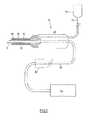
図1を参照すると、本発明の流れ適応チューブと共に用いるのに好適な水晶体乳化システムが示されている。水晶体乳化システム10は水晶体乳化ニードル11を備え、このニードル11は超音波ハンドピース20に連結され、弾性スリーブ12によって包囲されている。ハンドピース20は、典型的には制御装置(図示せず)に連結され、ニードル11を超音波周波数で振動させている。白内障の水晶体に接触するとき、ニードル11は、その振動によって、水晶体の核材料を破砕するものである。[Overview of preferred lens emulsification system]
Referring to FIG. 1, a lens emulsification system suitable for use with the flow adaptive tube of the present invention is shown. The
灌注ライン13は、灌注流体源14とハンドピース20との間に流体連通している。灌注流体は、ニードル11と弾性スリーブ12の内面16との間に形成された環15を介して、目に送給されるようになっている。吸引チューブ17は、ニードル11の内腔18と真空源19との間に流体連通し、破砕された核材料を患者の目から吸引することを可能にするものである。
操作において、超音波エネルギーは水晶体乳化ニードル11によって患者の水晶体の核材料に加えられる。水晶体乳化プロセス中に、灌注流体は、ニードル11と弾性スリーブ12との間の環15を介して、灌注容器(灌注流体源)14から目に供給される。同時に、破砕された核材料がニードル内腔18および吸引チューブ17を介して回収される。前述したように、内腔18を介する吸引によってニードル11を塞ぐように生じる大きい破片は、内腔18を介して吸引される材料の流量の急激な変化(サージ)を引き起こし、眼内圧力を大きく変動させることがある。本発明の吸引チューブは、このような閉塞後のサージを緩和し、その結果としての圧力変動を低減させることを意図している。 In operation, ultrasonic energy is applied by the
[本発明の流れ適応吸引チューブの説明]
本発明の原理によれば、図1の水晶体乳化システム10は、より高い流量の流体の流れに対する流体力学的抵抗を高めるように修正された内腔を有する吸引チューブを備えている。この修正は、多数の形態の1つを取ることが可能であり、チューブの内面に沿った輪郭特徴部、流れ経路内において自在に移動可能な妨害物、または流れの方向を変える1つ以上の屈曲部からなるとよい。[Description of Flow Adaptive Suction Tube of the Present Invention]
In accordance with the principles of the present invention, the
図2を参照すると、本発明の適応吸引チューブ30の第1例示的実施形態が示されている。チューブ30は、内腔36を画成する外面32および内面34を有している。本発明の原理によれば、内面34は、内腔内の乱流を高めることによって、より高い流量の流れに対する抵抗を高める輪郭特徴部40を備えている。特徴部40は、チューブの全長に沿って設けられてもよいし、またはチューブの1つ以上の不連続な区分に沿ってのみ設けられてもよい。さらに、特徴部は、図2に示されるように、チューブ30の円周の全体に沿って延在していてもよいし、またはその円周の限られた円弧のみに延在していてもよい。 Referring to FIG. 2, a first exemplary embodiment of the
好ましい一実施形態において、特徴部40はチューブの内面に溝として形成される螺旋襞または凹部42から構成されている。凹部42は、図示されるように、チューブの長さに沿って、かつ内面の円周に沿って、規則的な間隔を置いて配置されている。凹部42は、(図2に示されるような)半円の断面を有していてもよいし、または半楕円、矩形、三角形、正方形、菱形、または他の適切な形状の断面輪郭であってもよい。 In a preferred embodiment, the
図2をさらに参照すると、凹部42は、大きな破片が内腔36を閉塞する可能性を増大させることなく、内腔36内に乱流を生成するものである。具体的に、凹部42は、チューブを通過する流体の流体力学的抵抗を増大させることによって、乱流を高めている。有利には、流れに対する抵抗はより高い流量において増大するので、目の前房を萎ませるかまたはその一部を萎ませる可能性のある流体のサージおよびそれに付随する圧力変動に関連する危険を低減させている。さらに、特徴部40は、低流速において流れが乱流になるように、内腔内の流れパターンを変更するものである。 Still referring to FIG. 2, the
図3を参照すると、代替的実施形態が示されている。ここで、輪郭特徴部40は、チューブの内面から内腔36内に突出する隆線または耳部のような隆起44から構成されている。隆起44は、チューブの長さに沿って、かつ内腔36の円周に沿って、規則的な間隔を置いて螺旋パターンに配置される一連の半円筒状隆線として配置されていてもよい。あるいは、隆起44は内腔36の円周に沿って部分的にのみ延在していてもよいし、チューブの長さの選択される部分に沿ってのみ延在していてもよい。凹部42のように、隆起44はチューブ30内の流体力学的抵抗を高め、すでに知られている吸引チューブ内におけるよりも低流速および低真空レベルにおいて乱流を誘発するものである。 Referring to FIG. 3, an alternative embodiment is shown. Here, the
図4および図5において、さらに他の実施形態が示されている。ここで、輪郭特徴部40は、チューブ30の内面に形成される長手方向凹部46(図4)または長手方向隆起48(図5)から構成されている。長手方向凹部46または長手方向隆起48は、実質的に互いに平行であり、内腔36の円周に沿って規則的な間隔で離間されている。あるいは、凹部46または隆起48は、内腔36の周囲に沿って部分的にのみ延在していてもよいし、チューブの長さの選択された部分に沿ってのみ延在していてもよい。 Still another embodiment is shown in FIGS. 4 and 5. Here, the
当業者によってさらに理解され得るように、本発明の範囲から逸脱することなく、前述の輪郭特徴部の2つ以上の組合せが吸引チューブの内面に設けられてもよい。 As can be further appreciated by those skilled in the art, combinations of two or more of the aforementioned contour features may be provided on the inner surface of the suction tube without departing from the scope of the present invention.
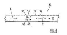
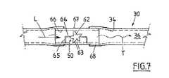
図6および図7を参照すると、かつ本発明の他の態様によれば、吸引チューブ30は、内腔36内に配置され、例えば、羽根またはプロペラのような自在に移動する物体50から構成されている。物体50は、内腔36内において流体の層流を分裂させて乱流を誘発するように、チューブ30内に嵌め込まれている。図6および図7において、層流は直線の矢印Lによって示され、乱流は曲線の矢印Tによって示されている。誘発された乱流は、内腔36内の流体力学的抵抗を増大させることになる。この乱流はチューブ内の流速の関数である。 With reference to FIGS. 6 and 7, and according to another aspect of the present invention, the
一例として、自在に移動する物体50は、内腔36内においてハブ58に取り付けられる羽根56から構成されている(図6)。この羽根56は、複数のアーム60を有している。あるいは、図7に描かれているように、自在に移動する物体50は、複数の突起63を有するプロペラ62からなっていてもよい。プロペラ62は、別体の短い長手方向セグメント67の内腔66において、アーム65に支持された軸64上に取り付けられている。セグメント67は、各端にアダプター68を備えているので、自在に移動する物体50はすでに知られている吸引チューブと連結して用いられることになる。勿論、当業者にとっては明らかなように、自在に移動する物体50は、本発明の範囲から逸脱することなく、他の形状であってもよい。さらに、層流を分裂させる1つ以上の自在に移動する物体を用いて、吸引チューブ内の流れを変更させてもよい。 As an example, the freely moving
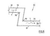
図8を参照すると、本発明の吸引チューブの他の代替的実施形態が示されている。ここで、吸引チューブ30は、1つ以上の角度の付いた屈曲部70から構成されている。屈曲部70は、内腔72内を流れる流体の方向を急変させ、流体がこれらの1つ以上の角度の付いた屈曲部を通過した後、(直線の矢印Lによって示される)層流が(曲線の矢印Tによって示される)乱流になる。好ましくは、屈曲角度は90°以下である。図7の実施形態に関して、図8の実施形態は、1つ以上の屈曲部とすでに知られている吸引チューブと、直列に並ぶセグメントを連結するアダプターを備える剛性チューブからなる別体のセグメントとして、実施してもよい。 Referring to FIG. 8, another alternative embodiment of the suction tube of the present invention is shown. Here, the
前述したように、白内障の外科手術に用いられるすでに知られている吸引チューブは、滑らかな内面を有している。このようなチューブ内の流体の流量は典型的に層流であり、ハーゲン・ポアズイユ(Hagen-Poiseuille)の式によって表わし得るものである。
Q = P×π×D4/(8×l×v)
ただし、Qは容積流量、Pは差圧、Dはチューブの断面直径、lは制限直径の長さ、およびvは流体の粘度である。As previously mentioned, already known suction tubes used in cataract surgery have a smooth inner surface. The flow rate of fluid in such a tube is typically laminar and can be represented by the Hagen-Poiseuille equation.
Q = P × π × D4 / (8 × l × v)
Where Q is the volumetric flow rate, P is the differential pressure, D is the cross-sectional diameter of the tube, l is the length of the limiting diameter, and v is the viscosity of the fluid.
チューブ内の流体の流れが乱流になる点は、レイノルド数(Reynolds number)によって決定される。
Re = d×V×D/v
ただし、Reはレイノルズ数、Vは流速、Dはチューブの断面直径、vは流体粘度である。
実験によれば、レイノルズ数が2000(下側臨界レイノルズ数)未満の場合、層流になりやすく、レイノルズ数が4000(上側臨界レイノルズ数)を越える場合、乱流になりやすいことが判明している。レイノルズ数が2000と4000との間にあるとき、チューブ内の流れの性質は不確実である。The point at which the fluid flow in the tube becomes turbulent is determined by the Reynolds number.
Re = d × V × D / v
Where Re is the Reynolds number, V is the flow velocity, D is the cross-sectional diameter of the tube, and v is the fluid viscosity.
According to experiments, it is found that when the Reynolds number is less than 2000 (lower critical Reynolds number), laminar flow tends to occur, and when the Reynolds number exceeds 4000 (upper critical Reynolds number), turbulence tends to occur. Yes. When the Reynolds number is between 2000 and 4000, the nature of the flow in the tube is uncertain.
チューブの内壁面の粗さを増すと、流れに対する抵抗が増し、乱流を誘発する傾向にある。流体が円形の断面を有していない一定長さの修正されたチューブ(例えば、図2〜図5を参照)を流れるとき、レイノルズ数は等価直径deを用いて計算され得る。
de=4×A/P
ただし、Aは流れ領域の断面、およびPは断面の浸辺長(wetted perimeter)である。従って、チューブの輪郭を変更することによって、乱流が促進されることになる。Increasing the roughness of the tube inner wall tends to increase resistance to flow and induce turbulence. When the fluid flows through a fixed length modified tube (eg, see FIGS. 2-5) that does not have a circular cross-section, the Reynolds number can be calculated using the equivalent diameter de.
de = 4 × A / P
Where A is the cross section of the flow region and P is the wetted perimeter of the cross section. Therefore, turbulence is promoted by changing the contour of the tube.
流体の流れが層流の場合、流体層間のせん断挙動および摩擦の殆どは壁から離れて生じることになる。壁面は摩擦因子(f)に対して比較的影響を及ぼさない。この摩擦因子(f)は、f=64/Re(Re:レイノルズ数)に従って、すなわち、レイノルズ数に逆比例して変化する。対照的に、流れが乱流の場合、チューブの内面の性質は摩擦因子に対して著しい影響を及ぼす。何故なら、せん断挙動およびその結果としての摩擦の多くが輪郭特徴部の近くで生じるからである。相対的な粗さは以下のように定義され得る。
εR =ε/d
ただし、εは表面粗さの高さであり、dはチューブ直径である。
ムーディ線図および上式を用いて、チューブ内の流体の流れに対する摩擦因子(f)を計算することが可能である。
f=0.0055*(1+(2000×εR+106/Re)1/3)If the fluid flow is laminar, most of the shear behavior and friction between the fluid layers will occur away from the wall. The wall surface has relatively little influence on the friction factor (f). This friction factor (f) changes according to f = 64 / Re (Re: Reynolds number), that is, inversely proportional to the Reynolds number. In contrast, when the flow is turbulent, the nature of the inner surface of the tube has a significant effect on the friction factor. This is because much of the shear behavior and the resulting friction occurs near the contour feature. The relative roughness can be defined as follows:
εR = ε / d
Where ε is the height of the surface roughness and d is the tube diameter.
Using the Moody diagram and the above equation, it is possible to calculate the friction factor (f) for the flow of fluid in the tube.
f = 0.0055* (1+ (2000 × εR +106 / Re)1/3 )
従って、チューブの内面を修正して不均一な表面を生成することによって、チューブ内の乱流を低流速かつ低真空度において乱流とし、流れに対する抵抗を増大させることができる。乱流はベルヌーイ(Bernoulli)の式によって定義され得る。
Q=SQRT(P×π2×D4)/(8×d))
ただし、Qは容積流量、Pは差圧、Dはチューブの断面直径、lは制限直径の長さ、vは流体の粘度、dは流体の密度である。
真空によって生成される真空レベルによって決定される同一の差圧に対して、同一の直径かつ同一の長さのチューブの場合、乱流によって生成される抵抗の増大によって、流量は小さくなるであろう。Therefore, by modifying the inner surface of the tube to produce a non-uniform surface, the turbulent flow in the tube can be made turbulent at a low flow rate and low vacuum, increasing the resistance to flow. Turbulence can be defined by the Bernoulli equation.
Q = SQRT (P × π2 × D4 ) / (8 × d))
Where Q is the volumetric flow rate, P is the differential pressure, D is the cross-sectional diameter of the tube, l is the length of the limiting diameter, v is the viscosity of the fluid, and d is the density of the fluid.
For a tube of the same diameter and length for the same differential pressure determined by the vacuum level produced by the vacuum, the flow rate will be reduced due to the increased resistance produced by the turbulent flow .
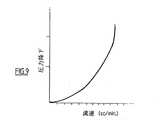
さらに、修正された吸引チューブによって流体の流れに対して与えられる抵抗は、低真空レベルでは比較的変化しないが、層流から乱流への遷移(これは、すでに知られている滑らかな内面を有するチューブにおけるよりも低真空レベルで生じる)によって真空レベルが大きくなると、それに比例して大きくなる。流れに対する抵抗による圧力降下は、流速の2乗に比例して変化する。従って、図9に描かれるように、流体の流速に対してプロットされる圧力降下は放物線を示し、低摩擦抵抗および層流のチューブと比較して、比較的小さな流速の変化が比較的大きな百分率の圧力降下の結果として生じることになる。 In addition, the resistance imparted to the fluid flow by the modified suction tube remains relatively unchanged at low vacuum levels, but the transition from laminar to turbulent (this is due to the already known smooth inner surface). As the vacuum level is increased (which occurs at a lower vacuum level than in the tube with), it increases proportionally. The pressure drop due to resistance to flow changes in proportion to the square of the flow velocity. Thus, as depicted in FIG. 9, the pressure drop plotted against the fluid flow rate exhibits a parabola, with a relatively small percentage change in the relatively small flow rate compared to low friction and laminar flow tubes. As a result of the pressure drop.
有利には、チューブの内面への輪郭特徴部の設置によって、水晶体乳化ニードルの核材料の破片を引き込む効率は低下しない。ニードル先端の閉塞が生じたとき、チューブ内における最初の真空の立ち上がりはすでに知られているチューブと同様であるが、その真空レベルが増大する時間は緩慢になる。閉塞抵抗を上回った直後における吸引ラインにおける負圧による流体の流れは、すでに知られているチューブにおけるよりも小さい。有利には、これは閉塞後のサージの大きさと期間の両方を低減させている。 Advantageously, the placement of the contour feature on the inner surface of the tube does not reduce the efficiency of drawing the core material debris of the phacoemulsifying needle. When the needle tip occlusion occurs, the initial vacuum build-up in the tube is similar to the already known tube, but the time for the vacuum level to increase is slowed down. The fluid flow due to negative pressure in the suction line immediately after exceeding the blockage resistance is less than in the already known tubes. Advantageously, this reduces both the magnitude and duration of the surge after occlusion.
本発明は、より高い真空レベルにおける流れに対する抵抗を増大させる修正された吸引チューブを提供するものである。これは、すでに知られている吸引チューブにおけるよりも前房の圧力および容積を安定させることになる。さらに、本発明の吸引チューブは、水晶体乳化中に、より高い真空レベルを用いることを可能にする。より高い真空レベルによって、ニードル先端への核の破片の引込みを増大させ、第2器具によって、破片をさらに小さい断片に破砕するのを容易にするものである。さらに、修正された吸引チューブの断面積および長さをすでに知られている吸引チューブと同一に形成することが可能になるので、水晶体材料の破片による閉塞の可能性を増大することがなくなる。 The present invention provides a modified suction tube that increases resistance to flow at higher vacuum levels. This will stabilize the anterior chamber pressure and volume more than in the already known suction tubes. Furthermore, the suction tube of the present invention allows higher vacuum levels to be used during lens emulsification. The higher vacuum level increases the retraction of the nuclear debris into the needle tip and the second instrument facilitates breaking the debris into smaller pieces. Furthermore, the cross-sectional area and length of the modified suction tube can be made the same as that of the already known suction tube, so that the possibility of blockage due to debris of the lens material is not increased.
すでに知られている吸引チューブは、押出成形されたプラスチック材料から形成され得るが、この場合、重合していないプラスチックが中心金型を備える円錐形状の押出ノズル内から流出する。この金型の形状が、吸引チューブの内腔の断面輪郭を決定し、通常は、円筒形状である。押出成形の速度および中心金型と周囲ノズルとの間の関係が、壁厚みを決定することになる。 Already known suction tubes can be formed from extruded plastic material, in which case unpolymerized plastic flows out from within a conical shaped extrusion nozzle with a central mold. The shape of this mold determines the cross-sectional profile of the lumen of the suction tube and is typically cylindrical. The speed of extrusion and the relationship between the central mold and the surrounding nozzle will determine the wall thickness.
図10aおよび図10bを参照すると、(図2に示される)螺旋襞付きの内腔を有する吸引チューブを製造するのに適した金型が示されている。金型90は歯車に類似し、中心円筒部92と、その外周に沿って実質的に等間隔で離間された複数の半円隆起94を有している。押出成形されるプラスチック材料を回転させながら押出ノズルから流出させることによって、螺旋パターンの溝または襞が内腔の内面に形成されることになる。回転速度が螺旋パターンのピッチを決定している。本発明の吸引チューブを製造するのに適した材料として、ポリ塩化ビニルおよびシリコンが挙げられる。当業者にとっては理解され得ることではあるが、修正された吸引チューブは、本発明の範囲から逸脱することなく、前述の押出成形方法以外の方法で製造することができる。 Referring to FIGS. 10a and 10b, there is shown a mold suitable for manufacturing a suction tube having a spiral barbed lumen (shown in FIG. 2). The
中心円筒部92および隆起94の寸法は、好ましくは、螺旋襞付きチューブの内腔の断面積がすでに知られている円形断面を有するチューブの断面積に相当するように定められている。さらに、中心円筒部92の外周に沿った各半円隆起の円弧長さは、以下のようにして計算され得る。
C=2×π×R/12
ただし、Rは中心円筒コアの半径である。
各半円に対する中心角α(ラジアン)は、以下の通りである。
α=C/R
ただし、Cは各半円の弦長さdである。
d=2×R×sin(α/2)
溝襞の矢印方向における高さhは、以下の通りである。
h=R−√(R2−r2)
ただし、rは溝襞の半円の半径である。
溝襞の半円隆起と中心円筒部92の円周との交差によって生じるセグメントの面積Sは、以下の通りである。
S=r2×ACOS((r−h)/r)−√(2×r×h−h2)×(r−h)
溝襞の面積fは、以下の通りである。
f=(r2×π)/2−S
溝襞付きチューブの全面積Tは、以下の通りである。
T=R2×π−8×fThe dimensions of the central
C = 2 × π × R / 12
Where R is the radius of the central cylindrical core.
The central angle α (radian) for each semicircle is as follows.
α = C / R
Where C is the chord length d of each semicircle.
d = 2 × R × sin (α / 2)
The height h in the direction of the arrow of the groove is as follows.
h = R−√ (R2 −r2 )
Where r is the radius of the semicircle of the groove.
The area S of the segment generated by the intersection of the semicircular ridge of the groove and the circumference of the central
S = r2 × ACOS ((r−h) / r) −√ (2 × r × h−h2 ) × (r−h)
The area f of the groove is as follows.
f = (r2 × π) / 2-S
The total area T of the grooved tube is as follows.
T = R2 × π-8 × f
好ましい一実施形態によれば、本発明の修正された螺旋襞付の吸引チューブは、約1.5mmの内径と3.12mmの外径を有している。なお、1.34mmの内径と0.173mmの半径を有する8個の均等に離間された溝襞を有する内腔を備えるチューブは、1.5mmの内径を有する内腔を備えるすでに知られているチューブと同一の全断面積を有している。本発明の修正された吸引チューブは、すでに知られているチューブにおけるのと同様の近位端と遠位端に取り付けられるコネクターを備えるように構成されていてもよく、この場合、すでに知られているチューブと同一の全長を有している。 According to one preferred embodiment, the modified helically barbed suction tube of the present invention has an inner diameter of about 1.5 mm and an outer diameter of 3.12 mm. It should be noted that a tube with a lumen having eight equally spaced flutes having an inner diameter of 1.34 mm and a radius of 0.173 mm is already known with a lumen having an inner diameter of 1.5 mm. It has the same total cross-sectional area as the tube. The modified suction tube of the present invention may be configured with connectors attached to the proximal and distal ends similar to those already known, in which case the already known Has the same overall length as the tube.
白内障を除去するためのエネルギー源として超音波を用いる場合に基づいて、本発明を説明したが、修正された吸引チューブは、白内障を除去するためのいかなる方法、すなわち、白内障を破砕し、水晶体材料を吸引によって除去するのに、レーザ、音波、回転チップ、インペラ、水流のような他のエネルギー源、および機械的な方法を用いる場合にも、用いられ得る。さらに、修正された吸引チューブは、流体または組織を吸引する他の医学的用途にも有利に用いられ得ることが想定される。 Although the present invention has been described based on using ultrasound as an energy source to remove cataracts, the modified suction tube is suitable for any method for removing cataracts, i.e., crushing cataracts and lens material. It can also be used when using lasers, sound waves, rotating tips, impellers, other energy sources such as water flow, and mechanical methods to remove the water. Furthermore, it is envisioned that the modified aspiration tube can be advantageously used in other medical applications that aspirate fluid or tissue.
さらに、前述したように、吸引チューブは、その全長にわたって、修正された内腔を備えてもよい。あるいは、さらに前述したように、修正された吸引チューブは、別体の装置としてすでに知られている吸引ライン内に挿入され得る柔軟性または剛性のあるセグメントとして、形成されていてもよい。さらに、修正された吸引チューブを吸引回路内に迂回または介在させ、それによって、吸引ラインの内腔内の流体の流量を変更するために、3方向タップが吸引ライン内に設けられていてもよい。 Furthermore, as previously mentioned, the suction tube may comprise a modified lumen over its entire length. Alternatively, as further described above, the modified suction tube may be formed as a flexible or rigid segment that can be inserted into a suction line already known as a separate device. Furthermore, a three-way tap may be provided in the suction line to bypass or interpose the modified suction tube in the suction circuit, thereby changing the flow rate of fluid in the lumen of the suction line. .
本発明の好ましい例示的実施形態を説明したが、本発明から逸脱することなく、種々の変更および修正がなされ得ることは、当業者にとっては明らかであろう。添付の特許請求項において、本発明の精神と範囲内にあるこのようなすべての変更および修正を包含することが意図されている。 While preferred exemplary embodiments of the present invention have been described, it will be apparent to those skilled in the art that various changes and modifications can be made without departing from the invention. The appended claims are intended to cover all such changes and modifications that are within the spirit and scope of the invention.
Claims (22)
Translated fromJapanese第1端および第2端を有し、かつ該第1端と第2端との間に延在する内腔を形成する内面を有する一定長さのチューブ
を備え、
前記内面は、前記内腔を通る流体の流れに対する抵抗を高める前記内腔と連通する複数の凹部または隆起をさらに画成している
ことを特徴とする吸引チューブ。In a suction tube for use with a lens emulsification system,
A length of tubing having an inner surface defining a lumen having a first end and a second end and extending between the first end and the second end;
The suction tube, wherein the inner surface further defines a plurality of recesses or ridges that communicate with the lumen to increase resistance to fluid flow through the lumen.
第1端および第2端を有し、かつ該第1端と第2端との間に延在する内腔を形成する内面を有する一定長さのチューブと、
前記内面の近くにおける層流の形成を阻止し、前記内腔を通る流体の流れに対する抵抗を高めるために、前記内腔内に配置される自在に移動する物体と
を備えていることを特徴とする吸引チューブ。In a suction tube for use with a lens emulsification system,
A length of tubing having an inner surface defining a lumen having a first end and a second end and extending between the first end and the second end;
A freely moving object disposed within the lumen to prevent laminar flow formation near the inner surface and to increase resistance to fluid flow through the lumen. Suction tube.
第1端および第2端を有し、かつ該第1端と第2端との間に延在する内腔を形成する内面を有する一定長さのチューブ
を備え、
前記チューブの一部は、前記内腔を通る流体の流れに対する抵抗を高めるために、90°以下の角度を有する1つ以上の屈曲部を備えている
ことを特徴とする吸引チューブ。In a suction tube for use with a lens emulsification system,
A length of tubing having an inner surface defining a lumen having a first end and a second end and extending between the first end and the second end;
A suction tube, wherein a portion of the tube comprises one or more bends having an angle of 90 ° or less to increase resistance to fluid flow through the lumen.
第1端および第2端を有し、かつ該第1端と第2端との間に延在する内腔を形成する内面を有する一定長さのチューブと、
前記内腔を通る流体の流れに対する抵抗を高めるために、前記内腔内に配置され、かつ前記内腔と連通する手段と
を備えていることを特徴とする装置。In an apparatus for use with a lens emulsification system,
A length of tubing having an inner surface defining a lumen having a first end and a second end and extending between the first end and the second end;
A device disposed in the lumen and in communication with the lumen to increase resistance to fluid flow through the lumen.
The means for increasing resistance to fluid flow through the lumen comprises a portion of the tube having one or more bends inclined at an angle of 90 degrees or less. Item 13. The device according to Item 12.
Applications Claiming Priority (2)
| Application Number | Priority Date | Filing Date | Title |
|---|---|---|---|
| AUPS2801AAUPS280102A0 (en) | 2002-06-07 | 2002-06-07 | Aspiration tubing |
| PCT/AU2003/000703WO2003103746A1 (en) | 2002-06-07 | 2003-06-06 | Flow adaptive aspiration tubing and devices |
Publications (2)
| Publication Number | Publication Date |
|---|---|
| JP2005528957Atrue JP2005528957A (en) | 2005-09-29 |
| JP2005528957A5 JP2005528957A5 (en) | 2006-07-20 |
Family
ID=3836363
Family Applications (1)
| Application Number | Title | Priority Date | Filing Date |
|---|---|---|---|
| JP2004510864APendingJP2005528957A (en) | 2002-06-07 | 2003-06-06 | Flow adaptive suction tube and device |
Country Status (8)
| Country | Link |
|---|---|
| US (1) | US7727179B2 (en) |
| EP (1) | EP1551475B1 (en) |
| JP (1) | JP2005528957A (en) |
| CN (1) | CN1658915A (en) |
| AT (1) | ATE536899T1 (en) |
| AU (1) | AUPS280102A0 (en) |
| CA (1) | CA2487818A1 (en) |
| WO (1) | WO2003103746A1 (en) |
Cited By (4)
| Publication number | Priority date | Publication date | Assignee | Title |
|---|---|---|---|---|
| JP2010532188A (en)* | 2007-07-06 | 2010-10-07 | カール ツァイス サージカル ゲーエムベーハー | Flow limiter for fluid flowing in suction path of surgical device, and surgical device |
| JP2014505516A (en)* | 2010-12-16 | 2014-03-06 | アルコン リサーチ, リミテッド | System and method for small bore suction |
| KR101843145B1 (en)* | 2017-02-20 | 2018-03-28 | 서울대학교산학협력단 | Suction tip for medical use |
| JP2022543305A (en)* | 2018-08-06 | 2022-10-11 | ナラクリシュナン ファミリー トラスト | Apparatus and method for phacoemulsification |
Families Citing this family (64)
| Publication number | Priority date | Publication date | Assignee | Title |
|---|---|---|---|---|
| US7803141B2 (en)* | 2003-08-12 | 2010-09-28 | Boston Scientific Scimed, Inc. | Device and method for direct delivery of a therapeutic using non-newtonian fluids |
| US7686825B2 (en) | 2004-03-25 | 2010-03-30 | Hauser David L | Vascular filter device |
| GB0423422D0 (en)* | 2004-10-21 | 2004-11-24 | Bard Inc C R | Medical device for fluid flow, and method of forming such device |
| CH697759B1 (en) | 2004-11-24 | 2009-02-13 | Oertli Instr Ag | Needle for an apparatus for phacoemulsification. |
| CH697769B1 (en) | 2004-11-24 | 2009-02-13 | Oertli Instr Ag | Needle for an apparatus for phacoemulsification. |
| US8241242B2 (en)* | 2005-03-30 | 2012-08-14 | Abbott Medical Optics Inc. | Phacoaspiration flow restrictor with bypass tube |
| US20100130937A1 (en)* | 2005-06-30 | 2010-05-27 | Abbott Vascular Inc. | Introducer sheath and methods of making |
| US9597063B2 (en)* | 2006-06-28 | 2017-03-21 | Abbott Laboratories | Expandable introducer sheath to preserve guidewire access |
| US8359723B2 (en) | 2005-06-30 | 2013-01-29 | Abbott Vascular Inc. | Introducer sheath and methods of making |
| US9352118B2 (en)* | 2005-06-30 | 2016-05-31 | Abbott Laboratories | Modular introducer and exchange sheath |
| US8440122B2 (en) | 2005-06-30 | 2013-05-14 | Abbott Vascular Inc. | Introducer sheath and methods of making |
| US20080004571A1 (en)* | 2006-06-28 | 2008-01-03 | Abbott Laboratories | Expandable introducer sheath |
| US9168359B2 (en) | 2005-06-30 | 2015-10-27 | Abbott Laboratories | Modular introducer and exchange sheath |
| US20070078440A1 (en)* | 2005-07-21 | 2007-04-05 | Perkins James T | Thin wall surgical irrigation tubing with longitudinal reinforcements |
| US20070149919A1 (en)* | 2005-07-21 | 2007-06-28 | Bausch & Lomb Incorporated | Concentric thin wall surgical irrigation tubing |
| US20070149950A1 (en)* | 2005-07-21 | 2007-06-28 | Bausch & Lomb Incorporated | Thin wall surgical irrigation tubing with longitudinal reinforcements |
| US20070032777A1 (en)* | 2005-07-21 | 2007-02-08 | Perkins James T | Concentric thin wall surgical irrigation tubing |
| US9889275B2 (en) | 2006-06-28 | 2018-02-13 | Abbott Laboratories | Expandable introducer sheath to preserve guidewire access |
| US20100198160A1 (en)* | 2006-06-28 | 2010-08-05 | Abbott Vascular Inc. | Expandable Introducer Sheaths and Methods for Manufacture and Use |
| US7981074B2 (en)* | 2006-11-02 | 2011-07-19 | Novartis Ag | Irrigation/aspiration system |
| US8333741B2 (en)* | 2006-11-10 | 2012-12-18 | Bausch & Lomb Incorporated | Phacoemulsification cannula with improved purchase |
| US20080200884A1 (en)* | 2007-02-20 | 2008-08-21 | Perkins James T | Thin wall surgical irrigation tubing with longitudinal reinforcements |
| US8753323B2 (en)* | 2007-06-13 | 2014-06-17 | Dana, LLC. | Vacuum surge suppressor for surgical aspiration systems |
| US8721594B2 (en)* | 2007-06-19 | 2014-05-13 | Alcon Research, Ltd. | Post-occlusion chamber collapse canceling system for a surgical apparatus and method of use |
| US20080319451A1 (en)* | 2007-06-21 | 2008-12-25 | Jaime Zacharias | Post-occlusion chamber collapse suppressing system for a surgical apparatus and method of use |
| US8631831B2 (en)* | 2008-09-04 | 2014-01-21 | Alcon Research, Ltd. | Multi-compliant tubing |
| US9149387B2 (en)* | 2008-09-04 | 2015-10-06 | Novartis Ag | Varying material properties of a single fluidic line in ophthalmology tubing |
| US20100130944A1 (en)* | 2008-11-21 | 2010-05-27 | Music Douglas E | Flow control devices for ophthalmic surgery |
| US7819837B2 (en)* | 2008-12-11 | 2010-10-26 | Bausch & Lomb Incorporated | Device for controlling flow rate of aspirated fluids |
| US8801653B2 (en)* | 2009-06-04 | 2014-08-12 | Armand Maaskamp | Surgical apparatus and methods asociated therewith |
| US9884166B2 (en)* | 2010-01-23 | 2018-02-06 | Duke University | Jetless intravenous catheters and mechanical assist devices for hand-injection of contrast media during dynamic tomography and methods of use |
| CN101843523A (en)* | 2010-05-28 | 2010-09-29 | 浙江舒友仪器设备有限公司 | Radio knife |
| WO2012017265A1 (en)* | 2010-08-02 | 2012-02-09 | Intertechnique | Tube with protrusions for inflatable harness of breathing mask |
| US20120059337A1 (en)* | 2010-09-01 | 2012-03-08 | Eran Eilat | Catheter with asymmetric or collapsible-expandable cross-section |
| US20120157969A1 (en)* | 2010-12-20 | 2012-06-21 | Martin Michael Mcculloch | Spiral flow infusion cannula |
| US8777931B2 (en) | 2011-08-19 | 2014-07-15 | Alcon Research, Ltd. | Retractable luer lock fittings |
| US9744332B2 (en) | 2012-01-18 | 2017-08-29 | Contech Medical, Inc. | Lubricious extruded medical tubing |
| US9845902B2 (en)* | 2012-05-13 | 2017-12-19 | InnerGeo LLC | Conduit for improved fluid flow and heat transfer |
| US9145469B2 (en) | 2012-09-27 | 2015-09-29 | Ticona Llc | Aromatic polyester containing a biphenyl chain disruptor |
| US10039898B2 (en)* | 2013-01-08 | 2018-08-07 | Biosense Webster (Israel) Ltd. | Catheter sheath introducer with directional retention damper |
| US20140228814A1 (en)* | 2013-02-09 | 2014-08-14 | Boston Scientific Scimed, Inc. | Expandable sheath |
| CN105307706B (en)* | 2013-05-15 | 2019-02-26 | 贝克顿·迪金森公司 | Vacuum pressure regulator used during blood collection |
| WO2014193953A2 (en)* | 2013-05-28 | 2014-12-04 | 1Co, Inc. | Intraocular lens peripheral surgical systems |
| WO2015041547A1 (en)* | 2013-09-23 | 2015-03-26 | Fisher & Paykel Healthcare Limited | Nasal cannula with turbulation elements |
| US10238406B2 (en) | 2013-10-21 | 2019-03-26 | Inari Medical, Inc. | Methods and apparatus for treating embolism |
| US20160030708A1 (en)* | 2014-07-30 | 2016-02-04 | Angiodynamics, Inc. | Rifled catheters and vascular access systems |
| CN113796927B (en) | 2015-10-23 | 2025-03-04 | 伊纳里医疗公司 | Intravascular treatment of vascular occlusion and related devices, systems and methods |
| ES2884058T3 (en)* | 2016-04-29 | 2021-12-10 | Saint Gobain Performance Plastics Corp | Peristaltic pump tubing with non-uniform lumen profile |
| FI3528717T3 (en) | 2016-10-24 | 2024-08-09 | Inari Medical Inc | Devices for treating vascular occlusion |
| CN109381255A (en)* | 2017-08-02 | 2019-02-26 | 百润红科技有限公司 | A kind of radio knife |
| WO2019050765A1 (en) | 2017-09-06 | 2019-03-14 | Inari Medical, Inc. | Hemostasis valves and methods of use |
| US20190170424A1 (en)* | 2017-12-01 | 2019-06-06 | Shanghai Ocean University | Jet nozzle structure of impact-type freezer |
| CN108144137A (en)* | 2018-01-19 | 2018-06-12 | 昆山韦睿医疗科技有限公司 | A kind of negative-pressure ward pipeline and negative pressure treatment systems |
| US11154314B2 (en) | 2018-01-26 | 2021-10-26 | Inari Medical, Inc. | Single insertion delivery system for treating embolism and associated systems and methods |
| US10918828B2 (en)* | 2018-05-14 | 2021-02-16 | Fresenius Medical Care Holdings, Inc. | Kink and compression tolerant medical tubing |
| CA3114285A1 (en) | 2018-08-13 | 2020-02-20 | Inari Medical, Inc. | System for treating embolism and associated devices and methods |
| JP7638273B2 (en) | 2019-10-16 | 2025-03-03 | イナリ メディカル, インコーポレイテッド | Systems, devices and methods for treating vascular obstructions |
| CN111632214A (en)* | 2020-05-15 | 2020-09-08 | 孙英贤 | Impeller inflation formula ventricle circulation auxiliary device |
| CN111939385B (en)* | 2020-08-18 | 2021-07-30 | 深圳市立心科学有限公司 | Syringe for viscous and incompressible fluids |
| JP2024513867A (en)* | 2021-04-16 | 2024-03-27 | アルコン インコーポレイティド | System and method for mitigating post-occlusion rupture surge |
| WO2023076579A1 (en)* | 2021-10-29 | 2023-05-04 | Arthrex, Inc. | Surgical device system |
| EP4463083A1 (en) | 2022-01-11 | 2024-11-20 | Inari Medical, Inc. | Devices for removing clot material from intravascularly implanted devices, and associated systems and methods |
| AU2023212952A1 (en)* | 2022-01-31 | 2024-07-25 | Inari Medical, Inc. | Aspiration catheters having grooved inner surfaces, and associated systems and methods |
| CN116407696B (en)* | 2023-04-14 | 2024-01-26 | 保定泰鑫德医疗器械制造有限公司 | Atraumatic sputum aspirator |
Family Cites Families (14)
| Publication number | Priority date | Publication date | Assignee | Title |
|---|---|---|---|---|
| US1596754A (en)* | 1923-10-30 | 1926-08-17 | Judson D Moschelle | Reenforced tubing |
| US3604420A (en)* | 1969-01-21 | 1971-09-14 | Bard Inc C R | Closed system drainage design |
| US4041947A (en)* | 1974-01-28 | 1977-08-16 | Cavitron Corporation | Flow control system |
| US5167620A (en)* | 1989-11-28 | 1992-12-01 | Alexandar Ureche | Eye surgery methods |
| WO1996038091A1 (en)* | 1995-06-02 | 1996-12-05 | Surgical Design Corporation | Phacoemulsification handpiece, sleeve, and tip |
| FR2740028B1 (en)* | 1995-10-20 | 1998-01-23 | Garnier Bernard | SUCTION CONTROL DEVICE FOR MICROSURGERY APPARATUS, IN PARTICULAR FOR EYE SURGERY |
| DE19651676A1 (en)* | 1995-12-22 | 1997-06-26 | Ruck & Partner Gmbh | Hollow needle for instrument for destroying eye lens and for sucking up emulsion of infusion fluid and lens residue |
| DE19628252A1 (en)* | 1996-07-12 | 1998-01-15 | Jochen Dr Med Kammann | Probe for removal of eye tissue |
| US5899884A (en)* | 1997-01-17 | 1999-05-04 | Stryker Corporation | Suction regulator |
| US6126628A (en)* | 1997-04-22 | 2000-10-03 | Johnson & Johnson Professional, Inc. | Fluid flow limiting device |
| US6478781B1 (en)* | 2000-04-11 | 2002-11-12 | Circuit Tree Medical, Inc. | Anterior chamber stabilizing device for use in eye surgery |
| US20020022810A1 (en)* | 1999-12-07 | 2002-02-21 | Alex Urich | Non-linear flow restrictor for a medical aspiration system |
| CA2421569A1 (en) | 2000-09-07 | 2002-03-14 | Robert J. Cionni | Surge-flow regulator for use in ophthalmic surgical aspiration |
| US20020128560A1 (en)* | 2001-03-09 | 2002-09-12 | Alex Urich | Surgical flow restrictor and filter |
- 2002
- 2002-06-07AUAUPS2801Apatent/AUPS280102A0/ennot_activeAbandoned
- 2003
- 2003-06-06ATAT03724661Tpatent/ATE536899T1/enactive
- 2003-06-06CNCN038131943Apatent/CN1658915A/enactivePending
- 2003-06-06WOPCT/AU2003/000703patent/WO2003103746A1/enactiveApplication Filing
- 2003-06-06USUS10/456,287patent/US7727179B2/ennot_activeExpired - Fee Related
- 2003-06-06JPJP2004510864Apatent/JP2005528957A/enactivePending
- 2003-06-06CACA002487818Apatent/CA2487818A1/ennot_activeAbandoned
- 2003-06-06EPEP03724661Apatent/EP1551475B1/ennot_activeExpired - Lifetime
Cited By (4)
| Publication number | Priority date | Publication date | Assignee | Title |
|---|---|---|---|---|
| JP2010532188A (en)* | 2007-07-06 | 2010-10-07 | カール ツァイス サージカル ゲーエムベーハー | Flow limiter for fluid flowing in suction path of surgical device, and surgical device |
| JP2014505516A (en)* | 2010-12-16 | 2014-03-06 | アルコン リサーチ, リミテッド | System and method for small bore suction |
| KR101843145B1 (en)* | 2017-02-20 | 2018-03-28 | 서울대학교산학협력단 | Suction tip for medical use |
| JP2022543305A (en)* | 2018-08-06 | 2022-10-11 | ナラクリシュナン ファミリー トラスト | Apparatus and method for phacoemulsification |
Also Published As
| Publication number | Publication date |
|---|---|
| EP1551475A1 (en) | 2005-07-13 |
| US7727179B2 (en) | 2010-06-01 |
| EP1551475A4 (en) | 2008-05-28 |
| WO2003103746A1 (en) | 2003-12-18 |
| AUPS280102A0 (en) | 2002-06-27 |
| ATE536899T1 (en) | 2011-12-15 |
| EP1551475B1 (en) | 2011-12-14 |
| CA2487818A1 (en) | 2003-12-18 |
| CN1658915A (en) | 2005-08-24 |
| US20040039351A1 (en) | 2004-02-26 |
Similar Documents
| Publication | Publication Date | Title |
|---|---|---|
| JP2005528957A (en) | Flow adaptive suction tube and device | |
| JP4704999B2 (en) | Cassette and surgical system | |
| JP4559401B2 (en) | Cassette and surgical system | |
| EP2161046B1 (en) | Irrigation/aspiration system | |
| EP3474793B1 (en) | Phacoemulsification handpiece with flexible impeller pump | |
| EP2651354B9 (en) | Systems for small bore aspiration | |
| KR20040049767A (en) | Non-linear flow restrictor for a medical aspiration system | |
| WO2005092258A1 (en) | Phacoemulsification needle | |
| US7758546B2 (en) | Variable flow device | |
| US7942853B2 (en) | Fluid chamber | |
| WO2006096335A2 (en) | Phacoemulsification tip | |
| US20070179438A1 (en) | Surge suppression method | |
| JP2006110338A (en) | Method for intraocular pressure stabilization during phacoemulsification | |
| US20220323669A1 (en) | Multi-function irrigation-aspiration tubing for ocular surgery devices | |
| AU2003229131A1 (en) | Flow adaptive aspiration tubing and devices | |
| WO2024027903A1 (en) | Multi-function irrigation-aspiration tubing for ocular surgery devices |
Legal Events
| Date | Code | Title | Description |
|---|---|---|---|
| A521 | Request for written amendment filed | Free format text:JAPANESE INTERMEDIATE CODE: A523 Effective date:20060602 | |
| A621 | Written request for application examination | Free format text:JAPANESE INTERMEDIATE CODE: A621 Effective date:20060602 | |
| A131 | Notification of reasons for refusal | Free format text:JAPANESE INTERMEDIATE CODE: A131 Effective date:20090526 | |
| A02 | Decision of refusal | Free format text:JAPANESE INTERMEDIATE CODE: A02 Effective date:20091104 |