JP2005527322A - Radiopaque markers with polarity for stents - Google Patents
Radiopaque markers with polarity for stentsDownload PDFInfo
- Publication number
- JP2005527322A JP2005527322AJP2004508701AJP2004508701AJP2005527322AJP 2005527322 AJP2005527322 AJP 2005527322AJP 2004508701 AJP2004508701 AJP 2004508701AJP 2004508701 AJP2004508701 AJP 2004508701AJP 2005527322 AJP2005527322 AJP 2005527322A
- Authority
- JP
- Japan
- Prior art keywords
- stent
- strut
- medical device
- struts
- region
- Prior art date
- Legal status (The legal status is an assumption and is not a legal conclusion. Google has not performed a legal analysis and makes no representation as to the accuracy of the status listed.)
- Pending
Links
Images


Classifications
- A—HUMAN NECESSITIES
- A61—MEDICAL OR VETERINARY SCIENCE; HYGIENE
- A61F—FILTERS IMPLANTABLE INTO BLOOD VESSELS; PROSTHESES; DEVICES PROVIDING PATENCY TO, OR PREVENTING COLLAPSING OF, TUBULAR STRUCTURES OF THE BODY, e.g. STENTS; ORTHOPAEDIC, NURSING OR CONTRACEPTIVE DEVICES; FOMENTATION; TREATMENT OR PROTECTION OF EYES OR EARS; BANDAGES, DRESSINGS OR ABSORBENT PADS; FIRST-AID KITS
- A61F2/00—Filters implantable into blood vessels; Prostheses, i.e. artificial substitutes or replacements for parts of the body; Appliances for connecting them with the body; Devices providing patency to, or preventing collapsing of, tubular structures of the body, e.g. stents
- A61F2/82—Devices providing patency to, or preventing collapsing of, tubular structures of the body, e.g. stents
- A61F2/86—Stents in a form characterised by the wire-like elements; Stents in the form characterised by a net-like or mesh-like structure
- A61F2/90—Stents in a form characterised by the wire-like elements; Stents in the form characterised by a net-like or mesh-like structure characterised by a net-like or mesh-like structure
- A61F2/91—Stents in a form characterised by the wire-like elements; Stents in the form characterised by a net-like or mesh-like structure characterised by a net-like or mesh-like structure made from perforated sheets or tubes, e.g. perforated by laser cuts or etched holes
- A61F2/915—Stents in a form characterised by the wire-like elements; Stents in the form characterised by a net-like or mesh-like structure characterised by a net-like or mesh-like structure made from perforated sheets or tubes, e.g. perforated by laser cuts or etched holes with bands having a meander structure, adjacent bands being connected to each other
- A—HUMAN NECESSITIES
- A61—MEDICAL OR VETERINARY SCIENCE; HYGIENE
- A61F—FILTERS IMPLANTABLE INTO BLOOD VESSELS; PROSTHESES; DEVICES PROVIDING PATENCY TO, OR PREVENTING COLLAPSING OF, TUBULAR STRUCTURES OF THE BODY, e.g. STENTS; ORTHOPAEDIC, NURSING OR CONTRACEPTIVE DEVICES; FOMENTATION; TREATMENT OR PROTECTION OF EYES OR EARS; BANDAGES, DRESSINGS OR ABSORBENT PADS; FIRST-AID KITS
- A61F2/00—Filters implantable into blood vessels; Prostheses, i.e. artificial substitutes or replacements for parts of the body; Appliances for connecting them with the body; Devices providing patency to, or preventing collapsing of, tubular structures of the body, e.g. stents
- A61F2/82—Devices providing patency to, or preventing collapsing of, tubular structures of the body, e.g. stents
- A61F2/86—Stents in a form characterised by the wire-like elements; Stents in the form characterised by a net-like or mesh-like structure
- A61F2/90—Stents in a form characterised by the wire-like elements; Stents in the form characterised by a net-like or mesh-like structure characterised by a net-like or mesh-like structure
- A61F2/91—Stents in a form characterised by the wire-like elements; Stents in the form characterised by a net-like or mesh-like structure characterised by a net-like or mesh-like structure made from perforated sheets or tubes, e.g. perforated by laser cuts or etched holes
- A—HUMAN NECESSITIES
- A61—MEDICAL OR VETERINARY SCIENCE; HYGIENE
- A61F—FILTERS IMPLANTABLE INTO BLOOD VESSELS; PROSTHESES; DEVICES PROVIDING PATENCY TO, OR PREVENTING COLLAPSING OF, TUBULAR STRUCTURES OF THE BODY, e.g. STENTS; ORTHOPAEDIC, NURSING OR CONTRACEPTIVE DEVICES; FOMENTATION; TREATMENT OR PROTECTION OF EYES OR EARS; BANDAGES, DRESSINGS OR ABSORBENT PADS; FIRST-AID KITS
- A61F2/00—Filters implantable into blood vessels; Prostheses, i.e. artificial substitutes or replacements for parts of the body; Appliances for connecting them with the body; Devices providing patency to, or preventing collapsing of, tubular structures of the body, e.g. stents
- A61F2/02—Prostheses implantable into the body
- A61F2/04—Hollow or tubular parts of organs, e.g. bladders, tracheae, bronchi or bile ducts
- A61F2/06—Blood vessels
- A61F2/07—Stent-grafts
- A—HUMAN NECESSITIES
- A61—MEDICAL OR VETERINARY SCIENCE; HYGIENE
- A61F—FILTERS IMPLANTABLE INTO BLOOD VESSELS; PROSTHESES; DEVICES PROVIDING PATENCY TO, OR PREVENTING COLLAPSING OF, TUBULAR STRUCTURES OF THE BODY, e.g. STENTS; ORTHOPAEDIC, NURSING OR CONTRACEPTIVE DEVICES; FOMENTATION; TREATMENT OR PROTECTION OF EYES OR EARS; BANDAGES, DRESSINGS OR ABSORBENT PADS; FIRST-AID KITS
- A61F2/00—Filters implantable into blood vessels; Prostheses, i.e. artificial substitutes or replacements for parts of the body; Appliances for connecting them with the body; Devices providing patency to, or preventing collapsing of, tubular structures of the body, e.g. stents
- A61F2/82—Devices providing patency to, or preventing collapsing of, tubular structures of the body, e.g. stents
- A61F2/86—Stents in a form characterised by the wire-like elements; Stents in the form characterised by a net-like or mesh-like structure
- A61F2/90—Stents in a form characterised by the wire-like elements; Stents in the form characterised by a net-like or mesh-like structure characterised by a net-like or mesh-like structure
- A61F2/91—Stents in a form characterised by the wire-like elements; Stents in the form characterised by a net-like or mesh-like structure characterised by a net-like or mesh-like structure made from perforated sheets or tubes, e.g. perforated by laser cuts or etched holes
- A61F2/915—Stents in a form characterised by the wire-like elements; Stents in the form characterised by a net-like or mesh-like structure characterised by a net-like or mesh-like structure made from perforated sheets or tubes, e.g. perforated by laser cuts or etched holes with bands having a meander structure, adjacent bands being connected to each other
- A61F2002/91525—Stents in a form characterised by the wire-like elements; Stents in the form characterised by a net-like or mesh-like structure characterised by a net-like or mesh-like structure made from perforated sheets or tubes, e.g. perforated by laser cuts or etched holes with bands having a meander structure, adjacent bands being connected to each other within the whole structure different bands showing different meander characteristics, e.g. frequency or amplitude
- A—HUMAN NECESSITIES
- A61—MEDICAL OR VETERINARY SCIENCE; HYGIENE
- A61F—FILTERS IMPLANTABLE INTO BLOOD VESSELS; PROSTHESES; DEVICES PROVIDING PATENCY TO, OR PREVENTING COLLAPSING OF, TUBULAR STRUCTURES OF THE BODY, e.g. STENTS; ORTHOPAEDIC, NURSING OR CONTRACEPTIVE DEVICES; FOMENTATION; TREATMENT OR PROTECTION OF EYES OR EARS; BANDAGES, DRESSINGS OR ABSORBENT PADS; FIRST-AID KITS
- A61F2/00—Filters implantable into blood vessels; Prostheses, i.e. artificial substitutes or replacements for parts of the body; Appliances for connecting them with the body; Devices providing patency to, or preventing collapsing of, tubular structures of the body, e.g. stents
- A61F2/82—Devices providing patency to, or preventing collapsing of, tubular structures of the body, e.g. stents
- A61F2/86—Stents in a form characterised by the wire-like elements; Stents in the form characterised by a net-like or mesh-like structure
- A61F2/90—Stents in a form characterised by the wire-like elements; Stents in the form characterised by a net-like or mesh-like structure characterised by a net-like or mesh-like structure
- A61F2/91—Stents in a form characterised by the wire-like elements; Stents in the form characterised by a net-like or mesh-like structure characterised by a net-like or mesh-like structure made from perforated sheets or tubes, e.g. perforated by laser cuts or etched holes
- A61F2/915—Stents in a form characterised by the wire-like elements; Stents in the form characterised by a net-like or mesh-like structure characterised by a net-like or mesh-like structure made from perforated sheets or tubes, e.g. perforated by laser cuts or etched holes with bands having a meander structure, adjacent bands being connected to each other
- A61F2002/91533—Stents in a form characterised by the wire-like elements; Stents in the form characterised by a net-like or mesh-like structure characterised by a net-like or mesh-like structure made from perforated sheets or tubes, e.g. perforated by laser cuts or etched holes with bands having a meander structure, adjacent bands being connected to each other characterised by the phase between adjacent bands
- A—HUMAN NECESSITIES
- A61—MEDICAL OR VETERINARY SCIENCE; HYGIENE
- A61F—FILTERS IMPLANTABLE INTO BLOOD VESSELS; PROSTHESES; DEVICES PROVIDING PATENCY TO, OR PREVENTING COLLAPSING OF, TUBULAR STRUCTURES OF THE BODY, e.g. STENTS; ORTHOPAEDIC, NURSING OR CONTRACEPTIVE DEVICES; FOMENTATION; TREATMENT OR PROTECTION OF EYES OR EARS; BANDAGES, DRESSINGS OR ABSORBENT PADS; FIRST-AID KITS
- A61F2/00—Filters implantable into blood vessels; Prostheses, i.e. artificial substitutes or replacements for parts of the body; Appliances for connecting them with the body; Devices providing patency to, or preventing collapsing of, tubular structures of the body, e.g. stents
- A61F2/82—Devices providing patency to, or preventing collapsing of, tubular structures of the body, e.g. stents
- A61F2/86—Stents in a form characterised by the wire-like elements; Stents in the form characterised by a net-like or mesh-like structure
- A61F2/90—Stents in a form characterised by the wire-like elements; Stents in the form characterised by a net-like or mesh-like structure characterised by a net-like or mesh-like structure
- A61F2/91—Stents in a form characterised by the wire-like elements; Stents in the form characterised by a net-like or mesh-like structure characterised by a net-like or mesh-like structure made from perforated sheets or tubes, e.g. perforated by laser cuts or etched holes
- A61F2/915—Stents in a form characterised by the wire-like elements; Stents in the form characterised by a net-like or mesh-like structure characterised by a net-like or mesh-like structure made from perforated sheets or tubes, e.g. perforated by laser cuts or etched holes with bands having a meander structure, adjacent bands being connected to each other
- A61F2002/9155—Adjacent bands being connected to each other
- A61F2002/91558—Adjacent bands being connected to each other connected peak to peak
- A—HUMAN NECESSITIES
- A61—MEDICAL OR VETERINARY SCIENCE; HYGIENE
- A61F—FILTERS IMPLANTABLE INTO BLOOD VESSELS; PROSTHESES; DEVICES PROVIDING PATENCY TO, OR PREVENTING COLLAPSING OF, TUBULAR STRUCTURES OF THE BODY, e.g. STENTS; ORTHOPAEDIC, NURSING OR CONTRACEPTIVE DEVICES; FOMENTATION; TREATMENT OR PROTECTION OF EYES OR EARS; BANDAGES, DRESSINGS OR ABSORBENT PADS; FIRST-AID KITS
- A61F2230/00—Geometry of prostheses classified in groups A61F2/00 - A61F2/26 or A61F2/82 or A61F9/00 or A61F11/00 or subgroups thereof
- A61F2230/0002—Two-dimensional shapes, e.g. cross-sections
- A61F2230/0028—Shapes in the form of latin or greek characters
- A61F2230/0054—V-shaped
- A—HUMAN NECESSITIES
- A61—MEDICAL OR VETERINARY SCIENCE; HYGIENE
- A61F—FILTERS IMPLANTABLE INTO BLOOD VESSELS; PROSTHESES; DEVICES PROVIDING PATENCY TO, OR PREVENTING COLLAPSING OF, TUBULAR STRUCTURES OF THE BODY, e.g. STENTS; ORTHOPAEDIC, NURSING OR CONTRACEPTIVE DEVICES; FOMENTATION; TREATMENT OR PROTECTION OF EYES OR EARS; BANDAGES, DRESSINGS OR ABSORBENT PADS; FIRST-AID KITS
- A61F2250/00—Special features of prostheses classified in groups A61F2/00 - A61F2/26 or A61F2/82 or A61F9/00 or A61F11/00 or subgroups thereof
- A61F2250/0014—Special features of prostheses classified in groups A61F2/00 - A61F2/26 or A61F2/82 or A61F9/00 or A61F11/00 or subgroups thereof having different values of a given property or geometrical feature, e.g. mechanical property or material property, at different locations within the same prosthesis
- A61F2250/0032—Special features of prostheses classified in groups A61F2/00 - A61F2/26 or A61F2/82 or A61F9/00 or A61F11/00 or subgroups thereof having different values of a given property or geometrical feature, e.g. mechanical property or material property, at different locations within the same prosthesis differing in radiographic density
- A—HUMAN NECESSITIES
- A61—MEDICAL OR VETERINARY SCIENCE; HYGIENE
- A61F—FILTERS IMPLANTABLE INTO BLOOD VESSELS; PROSTHESES; DEVICES PROVIDING PATENCY TO, OR PREVENTING COLLAPSING OF, TUBULAR STRUCTURES OF THE BODY, e.g. STENTS; ORTHOPAEDIC, NURSING OR CONTRACEPTIVE DEVICES; FOMENTATION; TREATMENT OR PROTECTION OF EYES OR EARS; BANDAGES, DRESSINGS OR ABSORBENT PADS; FIRST-AID KITS
- A61F2250/00—Special features of prostheses classified in groups A61F2/00 - A61F2/26 or A61F2/82 or A61F9/00 or A61F11/00 or subgroups thereof
- A61F2250/0058—Additional features; Implant or prostheses properties not otherwise provided for
- A61F2250/0096—Markers and sensors for detecting a position or changes of a position of an implant, e.g. RF sensors, ultrasound markers
- A61F2250/0098—Markers and sensors for detecting a position or changes of a position of an implant, e.g. RF sensors, ultrasound markers radio-opaque, e.g. radio-opaque markers
Landscapes
- Health & Medical Sciences (AREA)
- Engineering & Computer Science (AREA)
- Biomedical Technology (AREA)
- Heart & Thoracic Surgery (AREA)
- Life Sciences & Earth Sciences (AREA)
- Cardiology (AREA)
- Oral & Maxillofacial Surgery (AREA)
- Transplantation (AREA)
- Physics & Mathematics (AREA)
- Vascular Medicine (AREA)
- Optics & Photonics (AREA)
- Animal Behavior & Ethology (AREA)
- General Health & Medical Sciences (AREA)
- Public Health (AREA)
- Veterinary Medicine (AREA)
- Prostheses (AREA)
- Media Introduction/Drainage Providing Device (AREA)
- Materials For Medical Uses (AREA)
Abstract
Translated fromJapaneseDescription
Translated fromJapanese本発明は、ステント用の極性を有する放射線不透過マーカに関する。 The present invention relates to a radiopaque marker having polarity for a stent.
(発明の背景)
体内管腔においてステントを用いることは、よく知られている。ステントは、冠状動脈、腎動脈、腸骨動脈を含む末梢動脈、頸部の動脈、大脳動脈、胆管、尿道、卵管、気管支、気管、食道、前立腺、腸管といった様々な体内管において使用されてきた。ステントのサイズ及び設計は、ステントが必要とされる場所によって変更することができる。(Background of the Invention)
The use of stents in body lumens is well known. Stents have been used in various body vessels such as coronary, renal, peripheral arteries including iliac arteries, cervical arteries, cerebral arteries, bile ducts, urethra, fallopian tubes, bronchi, trachea, esophagus, prostate, intestinal tract. It was. The size and design of the stent can vary depending on where the stent is needed.
ステントは、通常、体内管腔の所望の位置まで非拡張状態で搬送された後に拡張される。ステントは、バルーン等の機械器具を使用して拡張されてもよく、ステント自体が自己拡張型ステントであってもよい。 A stent is typically expanded after it has been delivered unexpanded to a desired location in a body lumen. The stent may be expanded using a mechanical device such as a balloon, or the stent itself may be a self-expanding stent.
ステントは、通常、カテーテルを使用して体内管の所望の位置まで搬送される。バルーン拡張型であるか、自己拡張型であるか、或いはこれら両方の特徴を備えた型であるかにかかわらず、ステントは、カテーテルの一部上に配置され、体内管の目的領域まで蛇行する体内管を介して搬送される。 The stent is typically delivered to the desired location in the body vessel using a catheter. Whether it is balloon-expandable, self-expandable, or with both features, the stent is placed on a portion of the catheter and snakes to the target area of the body vessel It is transported through a body tube.
ステントの搬送及び配置を観察するために、ステントは、通常、X線透視法を用いて視認可能となる放射線不透過領域を有する。場合によっては、放射線不透過領域は、ステントの一領域を区別するようにめっきやコーティングが施される。また、放射線不透過材料からなるリベット、即ち挿入部材をステントに加える場合もある。リベット又はその他の挿入部材の使用は、ステントの個々のストラットの幅が0.005インチ(約0.127mm)よりも狭い場合には、特に有用である。しかしながら、リベット又は挿入部材が設けられている場合には、その他の改変をステントに加えないと、ステントの巻縮限度や、巻縮の均一性を減少させることがある。さらには、リベット又は挿入部材に近接するストラットは、ステントが巻縮されている間、リベット又は挿入部材により損傷を受けることがある。 In order to observe the delivery and placement of the stent, the stent typically has a radiopaque region that is visible using fluoroscopy. In some cases, the radiopaque region is plated or coated to distinguish one region of the stent. A rivet made of a radiopaque material, that is, an insertion member may be added to the stent. The use of rivets or other insertion members is particularly useful when the individual struts of the stent are narrower than 0.005 inches (about 0.127 mm). However, if rivets or inserts are provided, other modifications to the stent may reduce the stent crimp limit and the uniformity of the crimp. Furthermore, struts proximate to the rivet or insertion member can be damaged by the rivet or insertion member while the stent is being crimped.
ステントは、カバー付きの状態で使用されてもよく、カバーがない状態で使用されてもよい。被覆されたステントは、通常、ステントの周りに配置されるカバーを有しており、流体が側壁を通って流れるのを防止する。被覆されるのは、ステント全体であってもよく、ステントの一部のみであってもよい。ステント上のカバーは、血液の漏出を防止するために、動脈瘤の領域において好適に使用することができる。しかしながら、ステントの被覆部分を体内管の所望の領域に配置するには、手腕を問われることがあった。 The stent may be used with a cover or without a cover. Coated stents typically have a cover placed around the stent to prevent fluid from flowing through the sidewall. The entire stent may be covered, or only a part of the stent may be covered. A cover on the stent can be suitably used in the area of the aneurysm to prevent blood leakage. However, in order to place the covered portion of the stent in a desired region of the body vessel, the hand and arm are sometimes asked.
全体がより小さなサイズとなるように巻縮可能な放射線不透過マーカを備えたステントや、より小さなサイズとなるように巻縮可能な放射線不透過マーカを有する被覆されたステントが必要とされている。また、ステントの所望の部分を選択的に被覆する特殊なカバーを備えたステントも必要とされている。 There is a need for a stent with a radiopaque marker that can be crimped to a smaller size and a coated stent with a radiopaque marker that can be crimped to a smaller size. . There is also a need for stents with special covers that selectively cover desired portions of the stent.
本願において記載された全ての米国特許及びその他の文献は、その開示された内容全てが本明細書に開示されたものとする。 All U.S. patents and other references mentioned in this application are hereby incorporated by reference in their entirety.
本発明の範囲を限定することなく、請求される本発明の実施例の要約を以下に記載する。本発明の要約された実施例のさらなる詳細及び/又は本発明のさらなる実施例については、以下の発明の「詳細な説明」に記載される。 Without limiting the scope of the invention, a summary of the claimed embodiments of the invention is set forth below. Additional details of the summarized embodiments of the invention and / or further embodiments of the invention are set forth in the Detailed Description of the Invention below.
(発明の要約)
一実施例においては、本発明は、少なくとも1個の特殊ストラットを含む相互連結された複数のストラットを備えた医療用具に関する。特殊ストラットは、医療用具の長手軸に対して第1の湾曲を描く第1の領域を備える第1の側と、医療用具の長手軸に対して第2の湾曲を描く第2の領域を備える第2の側とを有する。第1の領域は第2の領域に対向しており、医療用具の長手軸に対して、第2の領域とは反対方向に湾曲している。特殊ストラットは、第1の領域と第2の領域に挟まれる領域において、特殊ストラットの他の部分よりも高い放射線不透過性を有する。1個、2個、3個、或いはそれより多い数のストラットが特殊ストラットの第1の側に近接して配置され、第1の側の形状に対してほぼ相補的な形状を有する。1個、2個、3個、或いはそれより多い数のストラットが特殊ストラットの第2の側に近接して配置され、第2の側の形状に対してほぼ相補的な形状を有する。特殊ストラットのそれぞれの側に、特殊ストラットの形状に対して相補的な形状を有する2個以上のストラットが設けられている場合には、特殊ストラットに近接するストラットは、特殊ストラットからの距離が大きくなるにしたがって、湾曲が小さくなることが望ましい。(Summary of the Invention)
In one embodiment, the invention relates to a medical device comprising a plurality of interconnected struts including at least one special strut. The special strut includes a first side having a first region that draws a first curve with respect to the longitudinal axis of the medical device, and a second region that draws a second curve with respect to the longitudinal axis of the medical device. And a second side. The first region faces the second region, and is curved in the opposite direction to the second region with respect to the longitudinal axis of the medical device. The special strut has a higher radiopacity than the other parts of the special strut in the region sandwiched between the first region and the second region. One, two, three, or more struts are disposed proximate to the first side of the special strut and have a shape that is substantially complementary to the shape of the first side. One, two, three, or more struts are disposed proximate to the second side of the special struts and have a shape that is substantially complementary to the shape of the second side. When two or more struts having a shape complementary to the shape of the special strut are provided on each side of the special strut, the strut close to the special strut has a large distance from the special strut. As it becomes, it is desirable that the curvature becomes smaller.
特殊ストラットは、医療用具の一端部に配置されていてもよく、ストラットの両端部に配置されていてもよく、また、医療用具の端部間に配置されていてもよい。一実施例においては、特殊ストラットは、医療用具の中央地点と医療用具の長さに沿った1/3地点との間に配置される。 The special strut may be disposed at one end of the medical device, may be disposed at both ends of the strut, or may be disposed between the end portions of the medical device. In one embodiment, the special strut is placed between the central point of the medical device and a third point along the length of the medical device.
望ましくは、医療用具は、少なくとも特殊ストラット近傍において、医療用具の周りに配置されるカバーをさらに備える。
医療用具は、通常、ステントの形態をとるが、ステントグラフト、グラフト、フィルタ、塞栓用具といった形態をとってもよい。Desirably, the medical device further includes a cover disposed around the medical device at least in the vicinity of the special strut.
The medical device usually takes the form of a stent, but may take the form of a stent graft, graft, filter, embolization device.
本発明はまた、幅広領域を有する少なくとも1個のストラットを含む相互連結された複数のストラットを備えるステントにも関する。第1ストラットは、幅広領域を備えたストラットの第1の側の近くに配置され、第2ストラットは、幅広領域を備えたストラットの第2の側の近くに配置される。全体的に見ると、第1及び第2のストラットは、幅広領域を有するストラットの形状に対して相補的な形状を有する。幅広領域を有するストラットの放射線不透過性は、ストラットの他の部分と比べると幅広領域において高くなっている。 The invention also relates to a stent comprising a plurality of interconnected struts including at least one strut having a wide region. The first strut is disposed near the first side of the strut with the wide area, and the second strut is disposed near the second side of the strut with the wide area. Overall, the first and second struts have a complementary shape to the shape of the strut having a wide region. The radiopacity of a strut having a wide region is higher in the wide region compared to other parts of the strut.
幅広領域を有するストラットは、ステントの一端部に配置されていてもよく、ストラットの両端部に配置されていてもよく、また、ステントの端部間に配置されていてもよい。一実施例においては、幅広領域を有するストラットは、ステントの中央地点とステントの長さに沿った1/3地点との間に配置される。 The strut having a wide region may be disposed at one end of the stent, may be disposed at both ends of the strut, or may be disposed between the ends of the stent. In one embodiment, a strut having a wide region is positioned between a central point of the stent and a third point along the length of the stent.
望ましくは、ステントは、少なくとも幅広領域を有するストラットの近傍において、ステントの周りに配置されるカバーをさらに備える。
本発明はまた、相互連結された複数のストラットを備える非拡張状態のステントにも関する。ストラットは、1個以上の中央ストラットと、中央ストラットの一方の側に設けられる第1ストラットと、中央ストラットの他方の側に設けられる第2ストラットとを含み、中央ストラットの一方の側の一部分は第1ストラットに、中央ストラットの他方の側の一部分は第2ストラットにそれぞれ入れ込まれる。望ましくは、中央ストラットは、ストラットの他の部分よりも放射線不透過性が高い部分を有しており、この放射線不透過部分は、第1及び第2のストラットに入れ込まれている。放射線不透過部分における中央ストラットの幅は、ストラットの他の部分の幅よりも広いことが望ましい。一実施例においては、放射線不透過部分は、球根状をなす。通常、中央ストラットは、ステントの中央領域に位置する。Desirably, the stent further comprises a cover disposed around the stent at least in the vicinity of the strut having a wide region.
The present invention also relates to a non-expanded stent comprising a plurality of interconnected struts. The strut includes one or more central struts, a first strut provided on one side of the central strut, and a second strut provided on the other side of the central strut, a portion of one side of the central strut being In the first strut, a portion of the other side of the central strut is inserted into the second strut. Desirably, the central strut has a portion that is more radiopaque than other portions of the strut, and this radiopaque portion is encased in the first and second struts. The width of the central strut in the radiopaque portion is preferably wider than the width of the other portions of the strut. In one embodiment, the radiopaque portion is bulbous. Usually the central strut is located in the central region of the stent.
中央ストラットは、ステントの一端部又はストラットの両端部に配置されてもよい。一実施例においては、中央ストラットは、ステントの中央地点とステントに沿った1/3地点との間に配置される。 The central strut may be located at one end of the stent or at both ends of the strut. In one embodiment, the central strut is positioned between the central point of the stent and 1/3 point along the stent.
望ましくは、ステントは、少なくとも中央ストラット近傍において、ステントの周りに配置されるカバーをさらに備える。 Desirably, the stent further comprises a cover disposed about the stent at least near the central strut.
本発明のさらなる詳細及び/又は実施例について、以下に説明する。
(詳細な説明)
本発明は様々な形態で実施することができるが、本明細書においては、特定の実施例について詳細に記載する。実施例の記載は、本発明の原理を例示するものであり、本発明を例示された特定の実施例に限定するものではない。Further details and / or examples of the invention are described below.
(Detailed explanation)
While this invention may be embodied in many different forms, there are described in detail herein specific embodiments. The description of the embodiments is illustrative of the principles of the invention and is not intended to limit the invention to the particular embodiments illustrated.
本願においては、特に明記されない限りは、図面における同様の符号は、同様の特徴をさす。また、本願においては、ステントという語は、ステントグラフトを含むものとする。 In this application, like reference numerals refer to like features unless otherwise specified. Further, in the present application, the term “stent” includes a stent graft.
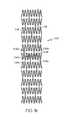
一実施例においては、本発明は、例えば図1aにおいて符号100にて示されるような、複数の相互連結されたストラット104を備えるステント等の医療用具に関する。ストラット104は、蛇行帯108の形状をなすように配置される。近接する蛇行帯同士は、図1に示されるように1個以上の連結ストラット112を介して連結されるか、直接連結されている。連結ストラットが用いられているステントでは、連結ストラットは、直線状をなしていてもよく、1個以上の屈曲部を有していてもよい。連結ストラットは、単一の領域において曲線状をなしていてもよく、全体にわたって曲線状をなしていてもよい。連結ストラットは、図1aに示されるようにステントの長手軸102にほぼ平行であってもよく、また、非平行であってもよい。連結ストラットの両端は、図1aに示されるように周方向において位置が揃っていてもよく、また、周方向において位置がずれていてもよい。蛇行帯が直接連結されている場合には、近接する蛇行帯の一部同士が互いに接する。 In one embodiment, the present invention relates to a medical device such as a stent comprising a plurality of
図1aに示されるように、ステント100は、少なくとも1個の特殊ストラット104aを備える。特殊ストラット104aは、長手軸に対して第1の湾曲を描く第1の領域を備えた第1の側106aと、長手軸に対して第2の湾曲を描く第2の領域を備えた第2の側106bとを有する。第1の領域106aは、第2の領域106bに対向する。第1の領域は、ステントの長手軸102に対して、第2の領域とは反対方向へ湾曲する。特殊ストラット104aの第1の側106aに近接する1個以上のストラット104b−104eは、第1の側の形状に対してほぼ相補的な形状を有しており、特殊ストラットの第2の側106bに近接する1個以上のストラット104f−104iは、第2の側の形状に対してほぼ相補的な形状を有している。 As shown in FIG. 1a, the
特殊ストラットは、第1の領域と第2の領域に挟まれる領域において、ストラットの他の部分よりもより高い放射線不透過性を有する。放射線不透過領域116により、X線透視法を用いて容易にステントの位置を確認することができる。図1aに示されるように、放射線不透過領域は円形をなす。放射線不透過領域は、他の形状をなすように構成されていてもよく、例えば、楕円形やその他の好適な形状であってもよい。放射線不透過領域にコーティングやその他の処理を施すことにより、或いは、単に放射線不透過領域におけるストラットの表面積をより広くすることにより、放射線不透過性を高めることができる。標準のX線透視技術を用いた場合、0.005インチ(約0.127mm)よりも細い幅のステンレス鋼製ストラットは、容易には視認できない。放射線不透過領域が0.005インチ(約0.127mm)を超える幅を有している、望ましくは0.005インチ(約0.127mm)を大きく超える幅を有している場合には、ストラットのその他の部分が視認できないとしても、放射線不透過領域をX線透視下で視認することができる。 Special struts are more radiopaque than the other parts of the struts in the region sandwiched between the first region and the second region. The
図1aに示される本発明の実施例では、特殊ストラットの両側にある複数のストラット104b−104iが互いに対して相補的な形状となるように、また、特殊ストラット104aに対して相補的な形状となるように湾曲しており、放射線不透過領域116は十分な広さを有している。補完ストラットの必要数は、ストラットの幅や放射線不透過領域のサイズに影響される。放射線不透過領域のサイズが大きくなり、かつ、ストラットの幅が狭くなるにしたがって、相補的な形状を有し、近接するストラットの必要数は多くなる。放射線不透過領域のサイズが小さくなり、かつ、ストラットの幅が狭くなるにしたがって、相補的な形状を有し、近接するストラットの必要数は少なくなる。図1aの実施例においては、特殊ストラットからの距離が大きくなるにしたがって、特殊ストラットに近接するストラットの湾曲は、小さくなる。 In the embodiment of the present invention shown in FIG. 1a, a plurality of
図1aの実施例においては、特殊ストラット104aは、ステントの両端部の間に位置する。望ましくは、特殊ストラットは、ステントの中央か、或いは、ステントの中央とステントの一端部との間に位置する。さらに望ましくは、特殊ストラットは、ステントの中央地点とステントに沿った1/3地点との間に位置する。 In the embodiment of FIG. 1a,
本発明の別の実施例においては、図1bに示されるように、放射線不透過領域116は、挿入部材、即ちリベットの形態で設けられている。リベットは、望ましくは円形をなし、特殊ストラット104aに挿入される。 In another embodiment of the invention, as shown in FIG. 1b, the
図1cの実施例においては、特殊ストラット104aに対して相補的な形状を有するより少数のストラット104b−104eが設けられている。特殊ストラット104a及びそれに近接するストラットについては、図1dにより詳細が示されている。 In the embodiment of FIG. 1c,
特殊ストラットがステントの一端部又は両端部に配置される構成も、本発明の範囲内に含まれるものとする。
図1a〜図1eにおいて例として示されるステントは、様々な方法で改変してもよい。個々の蛇行帯の山部及び谷部の数を増減してもよく、かつ/又は、個々の蛇行帯の湾曲が異なっていてもよい。A configuration in which the special struts are arranged at one end or both ends of the stent is also included in the scope of the present invention.
The stent shown as an example in FIGS. 1a-1e may be modified in various ways. The number of peaks and valleys of individual meander bands may be increased and / or the curvature of individual meander bands may be different.
ステントの蛇行帯は、図1a〜図1dに示される蛇行帯と同様のものであってもよく、異なる形状を有していてもよい。図1eに示されるように、近接するストラット同士は、互いにほぼ平行であり、かつ、ステントの長手軸にほぼ平行であってもよい。 The meandering band of the stent may be similar to the meandering band shown in FIGS. 1a to 1d and may have a different shape. As shown in FIG. 1e, adjacent struts may be substantially parallel to each other and substantially parallel to the longitudinal axis of the stent.
例えば図1fに示されるように、蛇行帯のストラットのうちいくつかの長さは、該蛇行帯の他のストラットの長さと異なっていてもよい。図1fのステントでは、ステントの両端に位置する第1の蛇行帯204は、第2の蛇行帯304に連結され、第2の蛇行帯304は、第3の蛇行帯404に連結される。第1の蛇行帯204は第2の蛇行帯304よりも長く、第2の蛇行帯304は第3の蛇行帯404よりも長い。状況に応じ、図1fに示されるように、山部及び谷部の数が、蛇行帯によって異なっていてもよい。第1の蛇行帯204は、第2の蛇行帯304に比べて、山部及び谷部の数が少ない。一方、第2の蛇行帯304は、第3の蛇行帯404に比べて、山部及び谷部の数が少ない。図1fのステントは、3個−6個−9個−9個−6個−3個のパターンを有している。近接する蛇行帯の山部の数は、3個−6個−9個−9個−6個−3個と変化している。ステントも、山部の数がステントの長さに沿って増加するように、3個−6個−9個のパターンをなしていてもよい。山部の割合が、1個−2個−3個−3個−2個−1個の倍数からなるパターンも、本発明の範囲内に含まれる。異なる数の山部を備える蛇行帯は、総円周長が同一であってもよく、異なっていてもよい。 For example, as shown in FIG. 1f, the length of some of the struts in the serpentine zone may be different from the length of the other struts in the serpentine zone. In the stent of FIG. 1 f, the first
図1fのステントは、放射線不透過性が高められた領域106を有するコネクタ112の形態をとる特殊ストラットを備える。図1fのステントは、特殊ストラットと近接する補完ストラットを図1a〜図1eに示されるような1個以上の蛇行帯の一部として設けるように改変されてもよい。本発明は、複数の蛇行帯と、蛇行帯間に延びる複数のコネクタとを備えるステントにも関する。このステントにおいては、1個以上のコネクタは、放射線不透過性が高められた領域を備えており、望ましくは、該領域は円形又は他の曲線状をなす領域の形態をとる。 The stent of FIG. 1f includes special struts in the form of
また、図1fは、本発明の別の特徴、即ち、放射線不透過性を高められた領域がステントの周面の周りに配置され、最も望ましくはステントの第1端部と第2端部との間に位置する、という特徴を示している。図1fの実施例においては、放射線不透過性を高められた領域は、ステントの中央領域の境界となっており、中央領域のステントのパターンは、ステントの端部のパターンとは異なっている。 FIG. 1f also illustrates another feature of the present invention, namely that the radiopaque areas are located around the circumference of the stent, most preferably the first and second ends of the stent. The characteristic of being located between is shown. In the embodiment of FIG. 1f, the radiopaque area is the boundary of the central area of the stent, and the pattern of the central area stent is different from the end pattern of the stent.
本発明は、図1a〜図1fに開示されるようなステントであって、特殊ストラットが図1a〜図1fに示される形状を有するが、ステントの他の部分と比較して、特殊ストラットが放射線不透過性に優れていたり、他の造影特性に優れているわけではないステントにも関する。 The present invention is a stent as disclosed in FIGS. 1 a-1 f, wherein the special strut has the shape shown in FIGS. 1 a-1 f, but compared to the other parts of the stent, the special strut is radiation. It also relates to stents that are not impermeable or have other contrast properties.
本願に開示される実施例のいずれについても、蛇行帯の山部は、図面において示されるように長手方向において位置が揃っていてもよく、ステントの長さに沿って異なる位置へ延びていてもよい。同様に、蛇行帯の谷部は、長手方向において位置が揃っていてもよく、ステントの長さに沿って異なる位置へ延びていてもよい。 For any of the embodiments disclosed herein, the ridges of the serpentine band may be aligned in the longitudinal direction as shown in the drawing or may extend to different positions along the length of the stent. Good. Similarly, the valleys of the serpentine band may be aligned in the longitudinal direction and may extend to different positions along the length of the stent.
螺旋設計のステントにも、本願に開示される特殊ストラットを設けることができる。単に例として示すが、図1aのステントは、蛇行構造が螺旋状の帯をなす形態となるように、改変されてもよい。 A spiral design stent may also be provided with the special struts disclosed herein. By way of example only, the stent of FIG. 1a may be modified so that the serpentine structure is in the form of a spiral band.
より一般的には、本願に開示される特殊ストラットと、該特殊ストラットに周方向において近接し、特殊ストラットに対して相補的な形状を有する1個以上のストラットとを設けて、任意の好適なステント設計を改変することができる。特殊ストラットの第1の側に近接する1個以上のストラットは、特殊ストラットの第1の側の形状に対してほぼ相補的な形状を有しており、特殊ストラットの第2の側に近接する1個以上のストラットは、第2の側の形状に対してほぼ相補的な形状を有している。特殊ストラットの第1及び第2の側は、ほぼ反対方向へ湾曲する領域を備える。 More generally, a special strut disclosed in the present application, and one or more struts adjacent to the special strut in the circumferential direction and having a shape complementary to the special strut are provided. The stent design can be modified. The one or more struts proximate to the first side of the special strut have a shape that is substantially complementary to the shape of the first side of the special strut and is proximate to the second side of the special strut. The one or more struts have a shape that is substantially complementary to the shape of the second side. The first and second sides of the special struts comprise regions that curve in approximately opposite directions.
異なる蛇行帯が異なる幅及び/又は太さを有するように、本願に開示される任意のステントを改変してもよい。ステントの様々な蛇行帯の総円周長は、同一であってもよく、異なっていてもよい。 Any of the stents disclosed herein may be modified so that different serpentine bands have different widths and / or thicknesses. The total circumference of the various serpentine bands of the stent may be the same or different.
放射線不透過領域を設ける場合には、該領域は任意の好適な手段を用いて設けることができる。
放射線不透過領域は、金、パラジウム、ロジウム、プラチナ、プラチナ−タングステン、プラチナ−イリジウム、イリジウム、タンタル、銀、モリブデン、ヨウ素、ヨウ素塩、ヨウ素化合物、バリウム、バリウム塩、バリウム化合物、ビスマス、ビスマス塩、ビスマス化合物、タングステン、レニウム、オスミウム、貴金属、パラジウム、又はパラジウム合金で形成することができる。When providing a radiopaque region, the region can be provided using any suitable means.
Radiopaque areas are gold, palladium, rhodium, platinum, platinum-tungsten, platinum-iridium, iridium, tantalum, silver, molybdenum, iodine, iodine salt, iodine compound, barium, barium salt, barium compound, bismuth, bismuth salt , Bismuth compounds, tungsten, rhenium, osmium, noble metals, palladium, or palladium alloys.
放射線不透過性は、ステントに放射線不透過材料をめっき又は塗布したり、ステントに放射線不透過粒子を圧入したり、ステントに放射線不透過材料をスエージングしたり、放射線不透過材料をステントに溶着又は接着したりすることにより、或いは従来技術において公知のその他の好適な手段を用いることにより、付与することができる。 Radiopaque means plating or applying a radiopaque material to the stent, pressing the radiopaque particles into the stent, swaging the radiopaque material into the stent, or welding the radiopaque material to the stent. Alternatively, it can be applied by bonding or by using any other suitable means known in the prior art.
本発明の別の実施例においては、特殊ストラットは、磁気共鳴映像法(MRI)における視認性が、第1の領域と第2の領域に挟まれる領域において、ストラットの他の領域と比べて高められるか、変化させられていてもよい。このような領域により、MRIを用いたステントの位置確認が容易になる。MRIによる視認性が変更された領域は、図1a〜図1fに示されるように円形であってもよく、楕円形やその他の好適な形状であってもよい。ステントに放射線不透過材料を付着させる上述された任意の技術を用いて特殊ストラットの所望の領域に造影剤を付着させることにより、当該領域における特殊ストラットのMRI特性を高めることができる。一例として、ガドリニウムを含む造影剤、例えばGd−EDTAとして従来技術で知られる造影剤を、特殊ストラットの所望の領域に塗布してもよい。有用であることを証明可能な他のMRI用造影剤は、米国特許第6,355,224号明細書及び同第6,350,431号明細書に開示されている。造影剤は、米国特許第6,333,021号明細書に開示されるように、造影剤を包含するカプセルの形態で付着させられていてもよい。 In another embodiment of the present invention, the special strut has a higher visibility in magnetic resonance imaging (MRI) in the region sandwiched between the first region and the second region than in other regions of the strut. Or may have been changed. Such a region facilitates confirmation of the position of the stent using MRI. The region in which the visibility by MRI is changed may be circular as shown in FIGS. 1a to 1f, or may be elliptical or other suitable shape. By attaching the contrast agent to the desired area of the special strut using any of the techniques described above for attaching a radiopaque material to the stent, the MRI characteristics of the special strut in that area can be enhanced. As an example, a contrast agent containing gadolinium, for example a contrast agent known in the prior art as Gd-EDTA, may be applied to the desired area of the special strut. Other MRI contrast agents that can prove useful are disclosed in US Pat. Nos. 6,355,224 and 6,350,431. The contrast agent may be attached in the form of a capsule containing the contrast agent, as disclosed in US Pat. No. 6,333,021.
ステントが有する特殊ストラットの数は、1個であってもよく、複数であってもよい。本発明の一実施例においては、ステントの両端部に1個ずつ、合計2個の特殊ストラットが設けられている。特殊ストラットがステントの他の位置に設けられる構成も、本発明の範囲内に含まれる。例えば、特殊ストラットは、ステントの中央に設けられていてもよい。ステントが単一の特殊ストラットを有している場合には、通常、ストラットはステントの端部やステントの中央に設けられる。特殊ストラットに近接するストラットは、特殊ストラットのそれぞれの側に対して相補的な湾曲を有する。特殊ストラットのそれぞれの側におけるストラットは、反対方向に湾曲する。 The number of special struts that the stent has may be one or plural. In one embodiment of the present invention, two special struts are provided, one at each end of the stent. Configurations in which special struts are provided at other positions of the stent are also included within the scope of the present invention. For example, the special strut may be provided in the center of the stent. When the stent has a single special strut, the strut is usually provided at the end of the stent or at the center of the stent. The struts adjacent to the special struts have a curvature that is complementary to each side of the special struts. The struts on each side of the special strut curve in the opposite direction.
本願に開示されるような特殊ストラットの使用は、ステントに限定されるわけではない。図1a〜図1fに示されるような特殊ストラットは、放射線不透過領域の有無にかかわらず、また、カバーの有無にかかわらず、フィルタや塞栓用具を含む、ストラットを備える他の医療用具においても使用することができる。 The use of special struts as disclosed in this application is not limited to stents. Special struts as shown in FIGS. 1a-1f are used in other medical devices with struts, including filters and embolization devices, with or without radiopaque areas and with or without covers can do.
本発明は、図1a〜図1eに例が示されるような、複数の相互連結されたストラット104を備え、長手軸102を有するステントにも関する。ストラット104は、幅広領域116を有する少なくとも1個のストラット104aを備える。複数の第1ストラット104b,104c,104d,104eは、ストラット104aの第1の側に近接し、複数の第2ストラット104f,104g,104h,104iは、ストラット104aの第2の側に近接する。第1ストラット104b−104eの形状と、第2ストラット104f−104iの形状は、全体で、幅広領域116を有するストラット104aの形状に対して相補的な形状となっている。 The present invention also relates to a stent having a plurality of
幅広領域は、放射線不透過性を有していてもよく、MRI特性が高められたり変化させられていてもよく、また、エコー特性が変化させられていてもよい。幅広領域は、ステントの一端部もしくは両端部に設けられていてもよく、かつ/又はステントの中央に設けられていてもよい。 The wide region may have radiopacity, MRI characteristics may be enhanced or changed, and echo characteristics may be changed. The wide region may be provided at one or both ends of the stent and / or may be provided at the center of the stent.
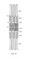
本発明は、図1aにおいて符号100にて示されるような、相互連結された複数のストラット104を備え、非拡張状態にあるステントにも関する。ストラットは、中央ストラット104aと、中央ストラットの一方の側に配置される第1ストラット104bと、中央ストラットの他方の側104fに配置される第2ストラットとを備える。中央ストラットの一方の側の一部は、第1ストラットに入れ込まれ、他方の側の一部は、第2ストラットに入れ込まれる。望ましくは、中央ストラットの入れ込まれた部分は、他のストラットと比較して高い放射線不透過性を有するか、或いは、変化させられたMRI特性又は超音波特性を有する。入れ込まれた部分は、ステントの一端部に設けられていてもよく、両端部に設けられていてもよく、また、ステントの中央に設けられていてもよい。上述したように、カバーが設けられていてもよい。 The present invention also relates to a stent in a non-expanded state comprising a plurality of
ステントは、1個以上の中央ストラットを有していてもよい。中央ストラットは、ステントの一端部もしくは両端部に設けられていてもよく、かつ/または、ステントの中央に設けられていてもよい。 The stent may have one or more central struts. The central strut may be provided at one or both ends of the stent and / or may be provided at the center of the stent.
図1a〜図1eに示されるような相補的な形状を有し、放射線不透過マーカを備えるストラットは、任意の好適なステント設計において使用することができる。また、図1fに示されるような放射線不透過性マーカを備える連結ストラットも、任意の好適なステント設計で用いることができる。非限定的な例として、ストラットは、均一径を有するステントで使用されてもよく、テーパ状をなすステント等の非均一の径を有するステントで使用されてもよい。ストラットは、均一の剛性を有するステントで使用されてもよく、非均一の剛性を有するステントで使用されてもよい。ストラットは、均一の壁厚を有するステントで使用されてもよく、非均一の壁厚を有するステントで使用されてもよい。 A strut having a complementary shape as shown in FIGS. 1a-1e and provided with a radiopaque marker can be used in any suitable stent design. Also, connecting struts with radiopaque markers as shown in FIG. 1f can be used with any suitable stent design. As a non-limiting example, struts may be used with stents having a uniform diameter, and may be used with stents having a non-uniform diameter, such as a tapered stent. The struts may be used with a stent having a uniform stiffness or may be used with a stent having a non-uniform stiffness. The struts may be used with stents having a uniform wall thickness or may be used with stents having a non-uniform wall thickness.
図1a〜図1eに示されるような相補的な形状を有し、放射線不透過性マーカを備えるストラット、及び/又は、図1fに示されるような放射線不透過性マーカを有する連結ストラットを備えるストラットは、分岐ステント(bifurcated stent)で使用してもよい。中央ストラットは、分岐ステントの各枝部の各端部に設けられてもよく、全ての端部ではなく、一部の端部に設けられていてもよい。本発明に基づき製造される分岐ステントは、1個以上のステントカバーを備えていてもよい。 A strut having a complementary shape as shown in FIGS. 1a to 1e and comprising a radiopaque marker and / or a connecting strut having a radiopaque marker as shown in FIG. 1f May be used in bifurcated stents. The central strut may be provided at each end of each branch of the bifurcated stent, and may be provided at a part of the ends instead of all ends. A branched stent manufactured in accordance with the present invention may include one or more stent covers.
ステントカバーの使用については、本願における開示で説明している。ステントの幅広マーカ領域の周りに配置された補完ストラットを使用することにより、ステントの巻縮性を向上させることができる。このような構成のステントは、通常、このように構成されないステントと比較して、マーカ領域におけるストラットを損傷することなく、より小径の状態で巻縮可能である。 The use of a stent cover is described in the disclosure herein. The use of complementary struts placed around the wide marker region of the stent can improve the retractability of the stent. A stent having such a configuration is usually capable of being crimped in a smaller diameter state without damaging the struts in the marker region as compared to a stent not configured in this way.
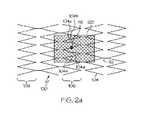
また、本発明のステントは、ステントの少なくとも一部を被覆する少なくとも1個のカバーを備えていてもよい。図2aの実施例においては、放射線不透過領域116及びカバー120を有する特殊ストラット104aを備えた本発明のステントの概略図が示されている。カバー120は、ステントの一部にわたってのみ延びている。ステント100は、動脈瘤の治療において使用することができる。ステントは、動脈瘤に血液が流れ込まないようにするために、或いは動脈瘤へ流れ込む血液を最小限にするために、被覆された部分120が動脈瘤上を延びるように動脈瘤のある血管内で位置合わせされてもよい。放射線不透過領域116は、カバーが動脈瘤の領域上に延びるようにステントを配置するのを補助するのに用いられてもよい。具体的には、放射線不透過領域は、バイプレーン透視法を用いながら、ステント上の軸方向及び周方向(polar) における位置を表示するのに使用することができる。これにより、ステントの正確な配置が可能になり、例えば、側枝の閉塞や動脈瘤のネックの不完全な被覆を防止することができる。 The stent of the present invention may include at least one cover that covers at least a part of the stent. In the embodiment of FIG. 2a, a schematic view of a stent of the present invention with a
本発明はまた、ステントの周面の周り全体にわたって延びるステントカバーや、ステントの全長にわたって延びるステントカバーや、ステントの周面の周り全体かつステントの全長にわたって延びるステントカバーの使用も意図するものである。1個以上のカバーを有するステントも、本発明の範囲に含まれるものとする。ステントの異なる領域が、別々のカバーで被覆されていてもよい。 The present invention also contemplates the use of a stent cover that extends around the entire circumference of the stent, a stent cover that extends the entire length of the stent, and a stent cover that extends around the entire circumference of the stent and the entire length of the stent. . Stents having one or more covers are also within the scope of the present invention. Different regions of the stent may be covered with different covers.
ステントカバーを備えた本発明のステントの例は、図2b〜図2eに示される。図2bのステント100は、ステントの周面の周り全体にわたって延びるカバー120を備える。ステントカバー120は、ステントの一部のみを被覆し、ステントよりも長さが短い。カバーは、ステントの中央のあたりにおいて、ステントの周りに配置されている。本発明の別の実施例においては、カバーは、ステントの各端部に配置される。X線透視法を用いたカバーの位置確認が容易になるように、少なくとも1個の、状況に応じ複数の放射線不透過領域116が設けられることが望ましい。図2bのステントにおいては、複数の放射線不透過領域116がステントカバーの両端において、ステントの周面の周りに設けられる。放射線不透過領域は、カバーの一端部及び/又はカバーの中央に設けられていてもよい。 An example of a stent of the present invention with a stent cover is shown in Figures 2b-2e. The
図2cの実施例においては、ステントカバー120は、ステント100の周面の周り全体ではないが、その殆どにわたって延びている。カバーの端は、状況に応じて曲線状をなしていてもよい。放射線不透過領域116は、カバー120の中央に設けられており、これにより、X線透視下でステントカバーの位置を視認することが容易になる。 In the embodiment of FIG. 2 c, the
図2dの実施例においては、ステント100は、状況に応じて長方形状であってもよいステントカバー120を備える。ステントカバー120は、ステントの中央においてステントの一部を被覆する。4個の放射線不透過領域116は、カバーの角部に設けられており、これにより、X線透視下でステントカバーの位置を視認することが容易になる。また、本発明に基づき設けられる放射線不透過領域の数を増減させてもよい。 In the embodiment of FIG. 2d, the
図2eの実施例においては、カバー120は、ステントの中央に設けられる。カバー120は、ステントの一部のみを被覆するだけであり、ステントの周面の周り全体にわたって延びてはいない。カバーは、ほぼ楕円形状をなしており、縁が曲線状をなす。望ましくは、少なくとも1個の放射線不透過領域116が設けられる。図2eに示されるように、放射線不透過領域116は、カバーの中央に位置する。放射線不透過領域は、ステントカバーの縁に沿って設けられていてもよい。本発明に基づき設けられる放射線不透過領域の数を、増加させてもよい。 In the embodiment of FIG. 2e, the
ステントカバーは、ポリマー材料及び金属を含む、任意の好適な材料で形成することができる。ポリマー材料の例としては、ポリテトラフルオロエチレン(ePTFE)、焼結されていないePTFE、ポリテトラフルオロエチレン、シリコーン、弾性材料や以下に開示される任意のグラフト材料を含む、その他のポリマー材料等が挙げられる。カバーが金属で形成されている場合には、金属は、網目状又は膜状の形態であることが望ましい。網目状、膜状、その他の好適な形態のいずれであっても、ニチノールが好適な金属の例として挙げられる。 The stent cover can be formed of any suitable material, including polymeric materials and metals. Examples of polymeric materials include polytetrafluoroethylene (ePTFE), unsintered ePTFE, polytetrafluoroethylene, silicone, other polymeric materials including elastic materials and any of the graft materials disclosed below, etc. Can be mentioned. When the cover is made of metal, the metal is preferably in the form of a mesh or film. Nitinol is an example of a suitable metal, whether in a network, film, or other suitable form.
本発明は、ステントの選択された部分のみを被覆するカバーを有するステントにも関する。このようなステントの例は、図2b〜図2eに示される。図2b〜図2eの実施例においては、ステントカバーは、ステントのほぼ中央に位置している。本発明の他の実施例においては、図2b〜図2eに示されるようなカバーは、ステントの中央以外の領域に設けられていてもよい。例えば、ステントの一端部又は両端部は、図2bに示されるような帯状のカバーを有していてもよく、図2c〜図2eに示されるような部分的な帯状のカバーを有していてもよい。カバーは、ステントの端部から僅かに内側に入った位置、例えばストラットの1個分又は2個分の長さだけ、ステントの内側へ入った位置に配置されていてもよい。本発明のステントは、2個以上のカバーを有していてもよい。 The present invention also relates to a stent having a cover that covers only selected portions of the stent. Examples of such stents are shown in Figures 2b-2e. In the embodiment of FIGS. 2b-2e, the stent cover is located approximately in the middle of the stent. In other embodiments of the present invention, a cover as shown in FIGS. 2b-2e may be provided in a region other than the center of the stent. For example, one or both ends of the stent may have a band-shaped cover as shown in FIG. 2b, and have a partial band-shaped cover as shown in FIGS. 2c to 2e. Also good. The cover may be arranged at a position slightly inward from the end of the stent, for example, at a position entering the inside of the stent by the length of one or two struts. The stent of the present invention may have two or more covers.
図2a〜図2eに示されるようなカバーを有する本発明のステントは放射線不透過領域を備えるが、本発明は、図2a〜図2eに示されるような放射線不透過領域のない、部分カバーを有するステントをも意図するものである。 While the stent of the present invention having a cover as shown in FIGS. 2a-2e comprises a radiopaque region, the present invention provides a partial cover without a radiopaque region as shown in FIGS. 2a-2e. Also intended are stents having.
ステントが放射線不透過領域を備えるのであれば、放射線不透過性は、上述したようにステントに付与されてもよく、或いは、カバーに直接付与されていてもよい。後者は、放射線不透過カバーを設けることにより、或いは、放射線不透過領域を備えるカバーを設けることにより、達成可能である。例えば、放射線不透過糸をカバーに組み込んだり、溶着やその他の好適な結合技術を用いて、放射線不透過マーカをカバーに接着したりしてもよい。 If the stent comprises a radiopaque region, radiopacity may be imparted to the stent as described above, or may be imparted directly to the cover. The latter can be achieved by providing a radiopaque cover or by providing a cover with a radiopaque region. For example, a radiopaque yarn may be incorporated into the cover, or a radiopaque marker may be adhered to the cover using welding or other suitable bonding techniques.
本発明のステントは、周知のステント製造技術を使用して製造されてもよい。本発明のステントの好適な製造方法には、レーザー切断、化学エッチング、管のスタンピングが含まれる。本発明のステントは、レーザー切断や化学エッチングを用いることにより、又はフラットシートのスタンピングを行い、同シートを巻き、さらに状況に応じて同シートの溶着を行うことにより、製造されてもよい。他の好適な製造技術には、所望の設計によるステントの電極放電加工、又は成形が含まれる。ステントはまた、例えば、環状帯等の個々の部分を溶着により一体化して製造されてもよい。また、その他任意の好適なステント製造工程を使用してもよい。 The stent of the present invention may be manufactured using well-known stent manufacturing techniques. Suitable manufacturing methods for the stent of the present invention include laser cutting, chemical etching, and tube stamping. The stent of the present invention may be manufactured by using laser cutting or chemical etching, or by stamping a flat sheet, winding the sheet, and further welding the sheet depending on the situation. Other suitable manufacturing techniques include electrodischarge machining or molding of the stent according to the desired design. Stents may also be manufactured by integrating individual parts such as, for example, an annular band by welding. Any other suitable stent manufacturing process may also be used.
本発明のステントの製造において、任意の好適なステント材料を使用することができる。このような材料の例には、ポリマー材料、金属、セラミック及び複合材料が含まれる。好適なポリマー材料には、サーモトロピック液晶ポリマー(LCP)が含まれる。ステントが金属で形成される場合には、形成材料の金属は、ステンレス鋼、エルジロイ等のコバルトクロム合金、タンタル、その他の塑性変形可能な金属であってもよい。他の好適な金属には、一般に「ニチノール」として知られるニッケル−チタン合金等の形状記憶金属、プラチナ/タングステン合金、チタン合金が含まれる。 Any suitable stent material can be used in the manufacture of the stent of the present invention. Examples of such materials include polymeric materials, metals, ceramics and composite materials. Suitable polymeric materials include thermotropic liquid crystal polymers (LCP). When the stent is made of metal, the forming material may be stainless steel, cobalt chromium alloy such as Elgiloy, tantalum, or other plastically deformable metal. Other suitable metals include shape memory metals such as nickel-titanium alloys commonly known as “Nitinol”, platinum / tungsten alloys, titanium alloys.
本発明は、本発明のステントにおいて2種類以上の材料を用いることも意図している。例えば、蛇行帯のいくつかをある材料で形成し、その他の蛇行帯を別の材料で形成してもよい。 The present invention also contemplates the use of more than one material in the stent of the present invention. For example, some of the serpentine bands may be formed from one material and the other serpentine bands may be formed from another material.
本発明のステントは、機械的に拡張可能な型であってもよく、自己拡張型であってもよく、これらのハイブリッド型であってもよい。本発明によれば、機械的に拡張可能なステントは、バルーンを含む任意の好適な機械器具を用いて拡張することができる。 The stent of the present invention may be a mechanically expandable type, a self-expanding type, or a hybrid type of these. In accordance with the present invention, a mechanically expandable stent can be expanded using any suitable mechanical device including a balloon.
本発明のステントは、ステントの様々な特性を向上させるために、様々な生体適合性コーティングを施してもよい。例えば、本発明のステントは、潤滑コーティングが施されていてもよい。本発明のステントはまた、時間の経過とともに薬剤を放出する、薬剤を含有したコーティングが施されていてもよい。 The stent of the present invention may be provided with various biocompatible coatings to improve various properties of the stent. For example, the stent of the present invention may be lubricated. The stent of the present invention may also be provided with a drug-containing coating that releases the drug over time.
本発明のステントは、糖、より一般的には炭水化物、及び/又はゼラチンを用いて、ステントを所望の体内位置に搬送する間、ステントをバルーン上に保持するようにしてもよい。ステントの処理に好適な他の化合物には、生分解ポリマーや、体内の流体に溶けるポリマーが含まれる。ステントの内側部分及び/又は外側部分は、化合物でコーティングしたり、化合物を含浸させたりしてもよい。ステント搬送中にステントをバルーン上に保持するために、機械的に保持する器具を使用することも可能である。そのために本発明のステントに他のコーティングを使用することも、本発明の範囲に含まれる。 The stent of the present invention may use sugar, more generally carbohydrates, and / or gelatin to hold the stent on the balloon while it is delivered to the desired body location. Other compounds suitable for stent processing include biodegradable polymers and polymers that are soluble in body fluids. The inner and / or outer portion of the stent may be coated with a compound or impregnated with a compound. It is also possible to use a mechanical holding device to hold the stent on the balloon during stent delivery. Therefore, the use of other coatings on the stent of the present invention is also within the scope of the present invention.
コーティングは、1つ以上の非遺伝物質からなる治療薬、遺伝物質、細胞、及びこれらの組み合わせや、他のポリマーコーティングを含んでいてもよい。
非遺伝物質からなる治療薬の例としては、抗血栓剤(ヘパリン、ヘパリン誘導体、ウロキナーゼ、PPack(デキストロフェニルアラニンプロリンアルギニンクロロメチルケトン)等);増殖抑制剤(エノキサプリン、アンジオペプチン、平滑筋細胞の増殖を阻害するモノクローナル抗体、ヒルジン、アセチルサリチル酸等);抗炎症剤(デキサメタゾン、プレドニソロン、コルチコステロン、ブデソニド、エストロゲン、サルファサラジン、メサラミン等);抗腫瘍剤/増殖抑制剤/抗有糸分裂剤(パクリタキセル、5−フルオロウラシル、シスプラチン、ビンブラスチン、ビンクリスチン、エポシロン類、エンドスタチン、アンジオスタチン、チミジンキナーゼ阻害剤等);麻酔薬(リドカイン、ブピバカイン、ロピバカイン等);抗血液凝固剤(D−Phe−Pro−Argクロロメチルケトン、RGDペプチド含有化合物、ヘパリン、アンチトロンビン化合物、血小板受容体拮抗剤、アンチトロンビン抗体、抗血小板受容体抗体、アスピリン、プロスタグランジン阻害剤、血小板阻害剤、ダニ由来の抗血小板ペプチド等);血管細胞増殖促進剤(成長因子阻害剤、成長因子受容体拮抗剤、転写活性化因子、翻訳促進因子等);血管細胞増殖阻害剤(成長因子阻害剤、成長因子受容体拮抗剤、転写抑制剤、翻訳抑制剤、複製阻害剤、阻害抗体、成長因子に対する抗体、成長因子及び細胞毒素で構成される二官能性分子、抗体及び細胞毒素で構成される二官能性分子等);コレステロール低下薬;血管拡張剤;体内における血管作用機構を阻害する薬剤等がある。The coating may include therapeutic agents consisting of one or more non-genetic materials, genetic material, cells, and combinations thereof, as well as other polymer coatings.
Examples of therapeutic agents composed of non-genetic substances include antithrombotic agents (heparin, heparin derivatives, urokinase, PPack (dextrophenylalanine proline arginine chloromethyl ketone), etc.); growth inhibitors (enoxapurine, angiopeptin, smooth muscle cells) Monoclonal antibodies that inhibit proliferation, hirudin, acetylsalicylic acid, etc.); anti-inflammatory agents (dexamethasone, prednisolone, corticosterone, budesonide, estrogen, sulfasalazine, mesalamine, etc.); antitumor agents / proliferation inhibitors / antimitotics Agents (paclitaxel, 5-fluorouracil, cisplatin, vinblastine, vincristine, epothilones, endostatin, angiostatin, thymidine kinase inhibitor, etc.); anesthetics (lidocaine, bupivacaine, ropivacaine, etc.); anti Liquid coagulant (D-Phe-Pro-Arg chloromethyl ketone, RGD peptide-containing compound, heparin, antithrombin compound, platelet receptor antagonist, antithrombin antibody, antiplatelet receptor antibody, aspirin, prostaglandin inhibitor, Platelet inhibitors, mite-derived antiplatelet peptides, etc.); vascular cell proliferation promoters (growth factor inhibitors, growth factor receptor antagonists, transcription activators, translational promoters, etc.); vascular cell proliferation inhibitors (growth factors) Inhibitor, growth factor receptor antagonist, transcription inhibitor, translation inhibitor, replication inhibitor, inhibitory antibody, antibody to growth factor, bifunctional molecule composed of growth factor and cytotoxin, antibody and cytotoxin A cholesterol-lowering drug; a vasodilator; a drug that inhibits the mechanism of vascular action in the body.
遺伝物質には、アンチセンスDNA;RNA;酸性及び塩基性繊維芽細胞増殖因子、血管内皮増殖因子、上皮増殖因子、トランスフォーミング増殖因子α及びβ、血小板由来血管内皮増殖因子、血小板由来増殖因子、腫瘍壊死因子α、肝細胞増殖因子、インスリン様増殖因子等の増殖因子を含む血管新生促進因子や、細胞分裂阻害剤(CD inhibitor)、チミジンキナーゼ(TK)、細胞増殖を妨げる他の物質等の細胞周期阻害剤や、骨形成タンパク質(BMP)ファミリー(即ちBMP−2、BMP−3、BMP−4、BMP−5、BMP−6(Vgr−1)、BMP−7(OP−1)、BMP−8、BMP−9、BMP−10、BMP−11、BMP−12、BMP−13、BMP−14、BMP−15、BMP−16、等が含まれる。望ましいBMPは、BMP−2、BMP−3、BMP−4、BMP−5、BMP−6、BMP−7)をコードするDNA;アンチセンスRNA;内因性の欠陥又は欠損を有する分子を置き換えるためのtRNA又はrRNAが含まれる。これら二量体のタンパク質は、ホモ二量体、ヘテロ二量体、又はこれらの組み合わせであってもよく、これらと他の分子の組み合わせであってもよい。或いは、又は、加えて、BMPのアップストリーム効果やダウンストリーム効果を誘導する分子を用いてもよい。これらの分子には、「ヘッジホッグ」タンパク質やこれをコードするDNAが含まれる。 Genetic material includes antisense DNA; RNA; acidic and basic fibroblast growth factor, vascular endothelial growth factor, epidermal growth factor, transforming growth factors α and β, platelet-derived vascular endothelial growth factor, platelet-derived growth factor, Tumor necrosis factor α, hepatocyte growth factor, insulin-like growth factor and other angiogenesis-promoting factors, cell division inhibitor (CD inhibitor), thymidine kinase (TK), other substances that interfere with cell growth, etc. Cell cycle inhibitors, bone morphogenetic protein (BMP) family (ie BMP-2, BMP-3, BMP-4, BMP-5, BMP-6 (Vgr-1), BMP-7 (OP-1), BMP -8, BMP-9, BMP-10, BMP-11, BMP-12, BMP-13, BMP-14, BMP-15, BMP-16, etc. are desirable. P is a DNA encoding BMP-2, BMP-3, BMP-4, BMP-5, BMP-6, BMP-7); an antisense RNA; a tRNA for replacing a molecule having an endogenous defect or defect Or rRNA. These dimeric proteins may be homodimers, heterodimers, or combinations thereof, or combinations of these with other molecules. Alternatively, or in addition, molecules that induce the upstream and downstream effects of BMP may be used. These molecules include “hedgehog” proteins and DNA encoding them.
細胞は、ヒト由来(自己由来又は同種異系)であってもよく、動物由来(異種)であってもよく、必要に応じて、移殖部位に影響を及ぼすタンパク質を搬送するために、遺伝子操作されたものであってもよい。細胞は、搬送媒体に組み込んでもよい。搬送媒体は、必要に応じ、細胞の機能と生存を維持するように構成することができる。 The cells may be human (autologous or allogeneic) or animal (heterologous) and, if necessary, genes to carry proteins that affect the site of transfer. It may have been manipulated. The cells may be incorporated into a carrier medium. The carrier medium can be configured to maintain cell function and survival as needed.
適切なポリマーコーティング材料には、ポリカルボン酸、セルロースアセテートやニトロセルロース等のセルロース系ポリマー、ゼラチン、ポリビニルピロリドン、架橋ポリビニルピロリドン、無水マレイン酸ポリマー等のポリ無水物、ポリアミド、ポリビニルアルコール、EVA等のビニルモノマーのコポリマー、ポリビニルエーテル、ポリビニル芳香族化合物、ポリエチレンオキシド、グリコサミノグリカン、多糖類、ポリエチレンテレフタレートを含むポリエステル、ポリアクリルアミド、ポリエーテル、ポリエーテルスルホン、ポリカーボネート、ポリプロピレンやポリエチレンや高分子量ポリエチレンを含むポリアルキレン、ポリテトラフルオロエチレン等のハロゲン化ポリアルキレン、ポリウレタン、ポリオルソエステル、タンパク質、ポリペプチド、シリコーン、シロキサンポリマー、ポリ乳酸、ポリグリコール酸、ポリカプロラクトン、ポリヒドロキシブチレートバリレート及びそのブレンドとコポリマー、ポリウレタン分散液(例えばベイドロール(BAYHDROL、登録商標)等のポリマー分散液からなるコーティング、フィブリン、コラーゲン及びコラーゲン誘導体、セルロースやデンプンやデキストランやアルギン酸塩及びその誘導体等の多糖類、ヒアルロン酸、スクアレンエマルジョン等が含まれる。米国マサチューセッツ州ナティック(Natick)に所在するボストンサイエンティフィック社(Boston Scientific Corporation) によりハイドロプラス(HYDROPLUS 、登録商標)として販売され、米国特許第5,091,205号明細書に記載されるポリアクリル酸は、特に望ましい。ポリ乳酸とポリカプロラクトンのコポリマーは、更に望ましい。 Suitable polymer coating materials include polycarboxylic acids, cellulose polymers such as cellulose acetate and nitrocellulose, polyanhydrides such as gelatin, polyvinyl pyrrolidone, crosslinked polyvinyl pyrrolidone and maleic anhydride polymers, polyamides, polyvinyl alcohol, EVA and the like. Vinyl monomer copolymers, polyvinyl ether, polyvinyl aromatic compounds, polyethylene oxide, glycosaminoglycans, polysaccharides, polyesters including polyethylene terephthalate, polyacrylamides, polyethers, polyethersulfones, polycarbonates, polypropylene and polyethylene and high molecular weight polyethylene Containing polyalkylene, halogenated polyalkylene such as polytetrafluoroethylene, polyurethane, polyorthoester, tan Polymer dispersions such as polymers, polypeptides, silicones, siloxane polymers, polylactic acid, polyglycolic acid, polycaprolactone, polyhydroxybutyrate valerate and blends and copolymers thereof, polyurethane dispersions (eg BAYHDROL®) Coatings, fibrin, collagen and collagen derivatives, polysaccharides such as cellulose, starch, dextran, alginate and its derivatives, hyaluronic acid, squalene emulsion, etc. Boston Scientific, located in Natick, Massachusetts, USA Polyacrylic acid sold as HYDROPLUS® by Boston Scientific Corporation and described in US Pat. No. 5,091,205 is particularly desirable. Polylactic acid and polycaprolactone copolymer is further preferable.
本願に開示される特殊ストラットは、X線透視法、MRI、その他の画像診断法においてより容易に視認できる部分を有しており、本願に開示される薬剤又は他の治療薬が組み込まれたステントの領域の位置の目印として使用してもよい。例えば、ステントの一部のみに治療薬を組み込んだ場合や、ステントの部位によって異なる種類の治療薬又は異なる量の治療薬を組み込んだ場合に、放射線不透過マーカを用いてステントの異なる部位を区別し、これらの部位を血管のそれぞれ所望される領域に正確に配置することができる。そのために、本発明は、1つ以上の治療薬を異なる量含有する少なくとも2個の領域を備えるステントにも関する。これらの領域は、二領域間や両領域の縁に設けられる放射線不透過マーカにより、区別される。 The special strut disclosed in the present application has a portion that can be more easily visually recognized in X-ray fluoroscopy, MRI, and other diagnostic imaging methods, and a stent incorporating the drug or other therapeutic agent disclosed in the present application. You may use as a mark of the position of this area | region. For example, radiopaque markers can be used to distinguish different parts of a stent when a therapeutic agent is incorporated into only a portion of the stent, or when different types of therapeutic agents or different amounts of therapeutic agent are incorporated depending on the stent site. In addition, these portions can be accurately arranged in respective desired regions of the blood vessel. To that end, the present invention also relates to a stent comprising at least two regions containing different amounts of one or more therapeutic agents. These areas are distinguished by radiopaque markers provided between the two areas or at the edges of both areas.
本発明のステントは、グラフトの基礎構造としても使用することができる。好適な被覆剤には、ナイロン、コラーゲン、PTFE及びePTFE、ポリエチレンテレフタレート及びケブラー(登録商標)、米国特許第5,824,046号明細書及び同第5,755,770号明細書に開示される任意の材料を含む。より一般的には、ポリエチレン、ポリプロピレン、ポリウレタン、ポリグリコール酸、ポリエステル、ポリアミド、及びこれらの混合物、ブレンド、コポリマー等の合成ポリマーを含む、公知のグラフト材料を使用することができる。 The stent of the present invention can also be used as a graft substructure. Suitable coatings are disclosed in nylon, collagen, PTFE and ePTFE, polyethylene terephthalate and Kevlar®, US Pat. Nos. 5,824,046 and 5,755,770. Includes any material. More generally, known graft materials can be used, including synthetic polymers such as polyethylene, polypropylene, polyurethane, polyglycolic acid, polyester, polyamide, and mixtures, blends, and copolymers thereof.
本発明のステントは、冠状動脈、腎動脈、腸骨動脈を含む末梢動脈、頸部の動脈、大脳動脈において使用することができる。しかしながら、本発明のステントは、血管系における使用に限定されるものではなく、動脈、静脈、胆管、尿道、卵管、気管支、気管、食道、前立腺、腸管等の他の体内構造において好適に使用されてもよい。なお、体内構造は、これらに限定されるものではない。 The stent of the present invention can be used in peripheral arteries including coronary artery, renal artery, iliac artery, cervical artery, and cerebral artery. However, the stent of the present invention is not limited to use in the vascular system, and is preferably used in other body structures such as arteries, veins, bile ducts, urethra, fallopian tubes, bronchi, trachea, esophagus, prostate, intestinal tract, May be. The internal structure is not limited to these.
本発明のステントを希望体内位置まで搬送するために、米国特許第6,123,712号明細書、同第6,120,522号明細書、同第5,957,930号明細書に開示されるような好適なステント搬送装置を使用することができる。搬送装置の選択は、自己拡張型ステント又はバルーン拡張型ステントのいずれを用いるかに左右される。本発明のステントは、1つ以上のステント保持スリーブを併用して搬送されてもよい。ステント保持スリーブの例は、米国特許仮出願第60/238178号明細書に開示されている。 US Pat. Nos. 6,123,712, 6,120,522, and 5,957,930 disclose delivery of the stent of the present invention to a desired body position. Any suitable stent delivery device can be used. The choice of delivery device depends on whether a self-expanding stent or a balloon expandable stent is used. The stent of the present invention may be delivered in combination with one or more stent holding sleeves. An example of a stent retaining sleeve is disclosed in US Provisional Patent Application No. 60/238178.
本発明はさらに、本願に開示されるようなステントを所望の体内位置まで搬送する方法にも関する。ステントは、カテーテル上に配置され、所望の体内位置まで搬送され、バルーン拡張型ステントの場合には拡張され、自己拡張型ステントの場合には、拡張できる状態にされる。 The invention further relates to a method of delivering a stent as disclosed herein to a desired in-vivo location. The stent is placed on the catheter, delivered to the desired in-vivo location, expanded in the case of a balloon expandable stent, and ready for expansion in the case of a self-expanding stent.
本発明は、さらに、一部のみ被覆されるステント又は他の医療用具を、動脈瘤のある血管領域に配置する方法に関する。この方法は、画像診断法用のマーカを備えたステント又は他の医療用具を準備する工程であって、ステント又は他の医療用具が、放射線不透過マーカの周りであって、かつマーカに近接するステントもしくは他の医療用具の一部の周りに配置されるカバーを備えることと、ステント又は他の医療用具を動脈瘤のある血管領域に搬送する工程と、ステント又は他の医療用具の画像を取得して、マーカの動脈瘤に対する位置を判定する工程と、ステント又は他の医療用具を必要に応じて再配置し、ステント又は他の医療用具の被覆された部分が動脈瘤を横切って延びるようにする工程とを含む。通常の場合、マーカは放射線不透過マーカであり、画像診断法はX線透視法を用いる。 The invention further relates to a method of placing a partially coated stent or other medical device in a vascular region with an aneurysm. The method includes the step of providing a stent or other medical device with a marker for diagnostic imaging, where the stent or other medical device is around and in proximity to the radiopaque marker. Providing a cover disposed around a portion of the stent or other medical device, delivering the stent or other medical device to a blood vessel region having an aneurysm, and acquiring an image of the stent or other medical device. Determining the position of the marker relative to the aneurysm and repositioning the stent or other medical device as necessary so that the covered portion of the stent or other medical device extends across the aneurysm. Including the step of. In a normal case, the marker is a radiopaque marker, and the diagnostic imaging method uses X-ray fluoroscopy.
上述された開示事項は、例示的なものであり、包括的なものではない。この記載は、当業者に対して、様々な変更例や別例を提案するものである。これらすべての別例及び変更例については、特許請求の範囲に含まれるものであり、特許請求の範囲における「〜からなる、〜を備える、〜で構成される」という語は「〜を含む」という意味であり、「〜に限定される」という意味ではない。当業者には、本願に記載された特定の実施例と均等である他の技術は、本願の請求項に包含されるものであることが理解されるであろう。 The above disclosure is illustrative and not exhaustive. This description proposes various modifications and alternatives to those skilled in the art. All of these alternatives and modifications are included in the scope of the claims, and the term “consisting of, comprising of” in the claims of “includes”. Does not mean “limited to”. Those skilled in the art will appreciate that other techniques equivalent to the specific embodiments described herein are within the scope of the claims.
さらに、従属請求項に記載された特定の特徴は、発明の範囲内において他の方法で互いに組み合わせることができ、本願は、従属請求項に記載された特徴のその他全ての組み合わせによる他の実施例についても、範囲が及ぶものとする。 Furthermore, the specific features recited in the dependent claims can be combined with each other in other ways within the scope of the invention, and this application is intended to exemplify other embodiments in accordance with all other combinations of the features recited in the dependent claims. Also, the scope shall be extended.
Claims (33)
Translated fromJapanese前記長手軸に対して第1の湾曲を描く第1の領域を備える第1の側と、前記長手軸に対して第2の湾曲を描く第2の領域を備える第2の側とを備える少なくとも1個の特殊ストラットであって、第1の領域は第2の領域に対向し、前記医療用具の長手軸に対して第2の領域とは反対方向に湾曲することと、前記特殊ストラットは第1の領域と第2の領域との間に放射線不透過マーカを有することと、
前記特殊ストラットの第1の側に近接して配置され、第1の側の形状に対してほぼ相補的な形状を有する1個以上のストラットと、
前記特殊ストラットの第2の側に近接して配置され、第2の側の形状に対してほぼ相補的な形状を有する1個以上のストラットと
を含む医療用具。A medical device comprising a plurality of struts having a longitudinal axis and connected to each other, the struts comprising:
At least a first side comprising a first region that draws a first curve with respect to the longitudinal axis, and a second side comprising a second region that draws a second curve with respect to the longitudinal axis. One special strut, the first region facing the second region, being curved in a direction opposite to the second region with respect to the longitudinal axis of the medical device; Having a radiopaque marker between the first region and the second region;
One or more struts disposed proximate to the first side of the special struts and having a shape substantially complementary to the shape of the first side;
A medical device comprising one or more struts disposed proximate to a second side of the special struts and having a shape substantially complementary to the shape of the second side.
前記幅広領域を有するストラットの第1の側の近くに配置される第1のストラットと、
前記幅広領域を有するストラットの第2の側の近くに配置される第2のストラットと、
第1及び第2のストラットが、全体として、幅広領域を有するストラットの形状に対して相補的な形状であることと
を含む、相互に連結された複数のストラットを備えたステント。At least one strut having a wide region that is more radiopaque than the rest, the strut having a predetermined shape;
A first strut disposed near a first side of the strut having the wide region;
A second strut disposed near a second side of the strut having the wide region;
A stent comprising a plurality of interconnected struts, wherein the first and second struts are generally complementary to the shape of a strut having a wide region.
Applications Claiming Priority (2)
| Application Number | Priority Date | Filing Date | Title |
|---|---|---|---|
| US10/063,937US20030225448A1 (en) | 2002-05-28 | 2002-05-28 | Polar radiopaque marker for stent |
| PCT/US2003/015051WO2003101343A1 (en) | 2002-05-28 | 2003-05-13 | Polar radiopaque marker for stent |
Publications (1)
| Publication Number | Publication Date |
|---|---|
| JP2005527322Atrue JP2005527322A (en) | 2005-09-15 |
Family
ID=29581832
Family Applications (1)
| Application Number | Title | Priority Date | Filing Date |
|---|---|---|---|
| JP2004508701APendingJP2005527322A (en) | 2002-05-28 | 2003-05-13 | Radiopaque markers with polarity for stents |
Country Status (7)
| Country | Link |
|---|---|
| US (1) | US20030225448A1 (en) |
| EP (1) | EP1515663B1 (en) |
| JP (1) | JP2005527322A (en) |
| AT (1) | ATE530141T1 (en) |
| AU (1) | AU2003234430A1 (en) |
| CA (1) | CA2482619A1 (en) |
| WO (1) | WO2003101343A1 (en) |
Cited By (2)
| Publication number | Priority date | Publication date | Assignee | Title |
|---|---|---|---|---|
| WO2008096512A1 (en)* | 2007-02-09 | 2008-08-14 | Piolax Medical Devices, Inc. | Stent |
| KR101790576B1 (en) | 2017-07-27 | 2017-11-20 | 주식회사 바이오알파 | Method for manufacturing a stent including a marker member |
Families Citing this family (73)
| Publication number | Priority date | Publication date | Assignee | Title |
|---|---|---|---|---|
| US20070073384A1 (en)* | 1995-03-01 | 2007-03-29 | Boston Scientific Scimed, Inc. | Longitudinally flexible expandable stent |
| US7204848B1 (en) | 1995-03-01 | 2007-04-17 | Boston Scientific Scimed, Inc. | Longitudinally flexible expandable stent |
| EP0884029B1 (en) | 1997-06-13 | 2004-12-22 | Gary J. Becker | Expandable intraluminal endoprosthesis |
| US10172730B2 (en)* | 1999-11-19 | 2019-01-08 | Vactronix Scientific, Llc | Stents with metallic covers and methods of making same |
| GB0020491D0 (en) | 2000-08-18 | 2000-10-11 | Angiomed Ag | Stent with attached element and method of making such a stent |
| AU2003270817B2 (en)* | 2002-09-26 | 2009-09-17 | Vactronix Scientific, Llc | High strength vacuum deposited nitionol alloy films, medical thin film graft materials and method of making same |
| US7331986B2 (en)* | 2002-10-09 | 2008-02-19 | Boston Scientific Scimed, Inc. | Intraluminal medical device having improved visibility |
| US8021418B2 (en)* | 2003-06-19 | 2011-09-20 | Boston Scientific Scimed, Inc. | Sandwiched radiopaque marker on covered stent |
| US20050064223A1 (en)* | 2003-09-22 | 2005-03-24 | Bavaro Vincent Peter | Polymeric marker with high radiopacity |
| DE10361942A1 (en)* | 2003-12-24 | 2005-07-21 | Restate Patent Ag | Radioopaque marker for medical implants |
| JP4542360B2 (en)* | 2004-03-30 | 2010-09-15 | テルモ株式会社 | Self-expanding in-vivo stent |
| DE102005013547B4 (en)* | 2005-03-23 | 2009-02-05 | Admedes Schuessler Gmbh | Aneurysm stent and process for its preparation |
| DE102005019612B4 (en) | 2005-04-27 | 2010-11-25 | Admedes Schuessler Gmbh | Mechanical locking of an X-ray marker in the eyelet of a stent or in another body implant |
| DE102005039136B4 (en) | 2005-08-18 | 2011-07-28 | Admedes Schuessler GmbH, 75179 | Improving the radiopacity and corrosion resistance of NiTi stents using sandwiched rivets |
| JP2009526572A (en)* | 2006-02-14 | 2009-07-23 | アンギオメット ゲゼルシャフト ミット ベシュレンクテル ハフツング ウント コムパニー メディツィンテヒニク コマンデイトゲゼルシャフト | Highly flexible stent and manufacturing method |
| WO2007105067A1 (en)* | 2006-03-14 | 2007-09-20 | Arterial Remodeling Technologies, S.A. | Method of monitoring positioning of polymeric stents |
| GB0609841D0 (en) | 2006-05-17 | 2006-06-28 | Angiomed Ag | Bend-capable tubular prosthesis |
| GB0609911D0 (en)* | 2006-05-18 | 2006-06-28 | Angiomed Ag | Bend-capable stent prosthesis |
| GB0613670D0 (en) | 2006-07-10 | 2006-08-16 | Angiomed Ag | Tubular metal prosthesis and method of making it |
| GB0616579D0 (en)* | 2006-08-21 | 2006-09-27 | Angiomed Ag | Self-expanding stent |
| GB0616729D0 (en) | 2006-08-23 | 2006-10-04 | Angiomed Ag | Method of welding a component to a shape memory alloy workpiece |
| GB0616999D0 (en)* | 2006-08-29 | 2006-10-04 | Angiomed Ag | Annular mesh |
| EP2063824B1 (en)* | 2006-09-07 | 2020-10-28 | Angiomed GmbH & Co. Medizintechnik KG | Helical implant having different ends |
| US8414637B2 (en)* | 2006-09-08 | 2013-04-09 | Boston Scientific Scimed, Inc. | Stent |
| US7988720B2 (en)* | 2006-09-12 | 2011-08-02 | Boston Scientific Scimed, Inc. | Longitudinally flexible expandable stent |
| GB0622465D0 (en) | 2006-11-10 | 2006-12-20 | Angiomed Ag | Stent |
| GB0624419D0 (en)* | 2006-12-06 | 2007-01-17 | Angiomed Ag | Stenting ring with marker |
| GB0703379D0 (en) | 2007-02-21 | 2007-03-28 | Angiomed Ag | Stent with radiopaque marker |
| US20080221670A1 (en)* | 2007-03-07 | 2008-09-11 | Claude Clerc | Radiopaque polymeric stent |
| US8545548B2 (en) | 2007-03-30 | 2013-10-01 | DePuy Synthes Products, LLC | Radiopaque markers for implantable stents and methods for manufacturing the same |
| US20080243226A1 (en)* | 2007-03-30 | 2008-10-02 | Fernandez Jose E | Implantable stents with radiopaque markers and methods for manufacturing the same |
| GB0706499D0 (en) | 2007-04-03 | 2007-05-09 | Angiomed Ag | Bendable stent |
| US7810223B2 (en)* | 2007-05-16 | 2010-10-12 | Boston Scientific Scimed, Inc. | Method of attaching radiopaque markers to intraluminal medical devices, and devices formed using the same |
| GB0717481D0 (en) | 2007-09-07 | 2007-10-17 | Angiomed Ag | Self-expansible stent with radiopaque markers |
| US9034007B2 (en) | 2007-09-21 | 2015-05-19 | Insera Therapeutics, Inc. | Distal embolic protection devices with a variable thickness microguidewire and methods for their use |
| US10022250B2 (en) | 2007-12-12 | 2018-07-17 | Intact Vascular, Inc. | Deployment device for placement of multiple intraluminal surgical staples |
| US9375327B2 (en) | 2007-12-12 | 2016-06-28 | Intact Vascular, Inc. | Endovascular implant |
| US8128677B2 (en) | 2007-12-12 | 2012-03-06 | Intact Vascular LLC | Device and method for tacking plaque to a blood vessel wall |
| US9603730B2 (en) | 2007-12-12 | 2017-03-28 | Intact Vascular, Inc. | Endoluminal device and method |
| US10166127B2 (en) | 2007-12-12 | 2019-01-01 | Intact Vascular, Inc. | Endoluminal device and method |
| US7896911B2 (en) | 2007-12-12 | 2011-03-01 | Innovasc Llc | Device and method for tacking plaque to blood vessel wall |
| EP2421479A2 (en)* | 2009-04-24 | 2012-02-29 | The U.S.A. As Represented By The Secretary, Department Of Health And Human Services | Stent for valve replacement |
| AU2014280976B2 (en)* | 2010-07-08 | 2017-07-06 | Intact Vascular, Inc. | Deployment device for placement of multiple intraluminal surgical staples |
| US20120022578A1 (en)* | 2010-07-20 | 2012-01-26 | Cook Medical Technologies Llc | Frame-based vena cava filter |
| JP2014508559A (en) | 2010-12-30 | 2014-04-10 | ボストン サイエンティフィック サイムド,インコーポレイテッド | Multi-stage open stent design |
| WO2012119037A1 (en) | 2011-03-03 | 2012-09-07 | Boston Scientific Scimed, Inc. | Stent with reduced profile |
| EP2680797B1 (en) | 2011-03-03 | 2016-10-26 | Boston Scientific Scimed, Inc. | Low strain high strength stent |
| US10285831B2 (en) | 2011-06-03 | 2019-05-14 | Intact Vascular, Inc. | Endovascular implant |
| CN110464520A (en) | 2012-01-25 | 2019-11-19 | 因特脉管有限公司 | Intracavitary unit and method |
| CA3113910C (en) | 2012-08-10 | 2023-09-19 | Abiomed, Inc. | Graft anchor devices, systems, and methods |
| WO2014028913A1 (en)* | 2012-08-17 | 2014-02-20 | The Regents Of The University Of California | Dual rotational stent apparatus and method for endovascular treatment of aneurysms |
| US10561509B2 (en) | 2013-03-13 | 2020-02-18 | DePuy Synthes Products, Inc. | Braided stent with expansion ring and method of delivery |
| CN105228688B (en) | 2013-03-15 | 2019-02-19 | 伊瑟拉医疗公司 | Vascular treatment devices and methods |
| US8715314B1 (en) | 2013-03-15 | 2014-05-06 | Insera Therapeutics, Inc. | Vascular treatment measurement methods |
| US8679150B1 (en) | 2013-03-15 | 2014-03-25 | Insera Therapeutics, Inc. | Shape-set textile structure based mechanical thrombectomy methods |
| US8690907B1 (en) | 2013-03-15 | 2014-04-08 | Insera Therapeutics, Inc. | Vascular treatment methods |
| US9943628B2 (en)* | 2014-07-30 | 2018-04-17 | Medtronic Vascular Inc. | Welded stent with radiopaque material localized at the welds and methods |
| US10206796B2 (en) | 2014-08-27 | 2019-02-19 | DePuy Synthes Products, Inc. | Multi-strand implant with enhanced radiopacity |
| US9433520B2 (en) | 2015-01-29 | 2016-09-06 | Intact Vascular, Inc. | Delivery device and method of delivery |
| US9375336B1 (en) | 2015-01-29 | 2016-06-28 | Intact Vascular, Inc. | Delivery device and method of delivery |
| US10709555B2 (en)* | 2015-05-01 | 2020-07-14 | Jenavalve Technology, Inc. | Device and method with reduced pacemaker rate in heart valve replacement |
| US10993824B2 (en) | 2016-01-01 | 2021-05-04 | Intact Vascular, Inc. | Delivery device and method of delivery |
| US10052185B2 (en) | 2016-02-12 | 2018-08-21 | Covidien Lp | Vascular device marker attachment |
| US10265089B2 (en) | 2016-02-12 | 2019-04-23 | Covidien Lp | Vascular device visibility |
| CN108697423A (en) | 2016-02-16 | 2018-10-23 | 伊瑟拉医疗公司 | The part flow arrangement of suction unit and anchoring |
| US10076428B2 (en) | 2016-08-25 | 2018-09-18 | DePuy Synthes Products, Inc. | Expansion ring for a braided stent |
| US10292851B2 (en) | 2016-09-30 | 2019-05-21 | DePuy Synthes Products, Inc. | Self-expanding device delivery apparatus with dual function bump |
| US11660218B2 (en) | 2017-07-26 | 2023-05-30 | Intact Vascular, Inc. | Delivery device and method of delivery |
| GB201718299D0 (en) | 2017-11-03 | 2017-12-20 | Ab Wasstand Dev | Stents |
| AU2019204522A1 (en) | 2018-07-30 | 2020-02-13 | DePuy Synthes Products, Inc. | Systems and methods of manufacturing and using an expansion ring |
| US10278848B1 (en) | 2018-08-06 | 2019-05-07 | DePuy Synthes Products, Inc. | Stent delivery with expansion assisting delivery wire |
| US10456280B1 (en) | 2018-08-06 | 2019-10-29 | DePuy Synthes Products, Inc. | Systems and methods of using a braided implant |
| US11039944B2 (en) | 2018-12-27 | 2021-06-22 | DePuy Synthes Products, Inc. | Braided stent system with one or more expansion rings |
Family Cites Families (31)
| Publication number | Priority date | Publication date | Assignee | Title |
|---|---|---|---|---|
| US5091205A (en)* | 1989-01-17 | 1992-02-25 | Union Carbide Chemicals & Plastics Technology Corporation | Hydrophilic lubricious coatings |
| US5609627A (en)* | 1994-02-09 | 1997-03-11 | Boston Scientific Technology, Inc. | Method for delivering a bifurcated endoluminal prosthesis |
| JP2825452B2 (en)* | 1994-04-25 | 1998-11-18 | アドヴァンスド カーディオヴァスキュラー システムズ インコーポレーテッド | Radiopak stent marker |
| US6623033B2 (en)* | 1994-05-23 | 2003-09-23 | Automotive Technologies International, Inc. | Airbag inflation control system and method |
| US6333021B1 (en)* | 1994-11-22 | 2001-12-25 | Bracco Research S.A. | Microcapsules, method of making and their use |
| US5755770A (en)* | 1995-01-31 | 1998-05-26 | Boston Scientific Corporatiion | Endovascular aortic graft |
| US6334871B1 (en)* | 1996-03-13 | 2002-01-01 | Medtronic, Inc. | Radiopaque stent markers |
| IL117472A0 (en)* | 1996-03-13 | 1996-07-23 | Instent Israel Ltd | Radiopaque stent markers |
| US5824042A (en)* | 1996-04-05 | 1998-10-20 | Medtronic, Inc. | Endoluminal prostheses having position indicating markers |
| US6123712A (en)* | 1996-08-23 | 2000-09-26 | Scimed Life Systems, Inc. | Balloon catheter with stent securement means |
| US5772669A (en)* | 1996-09-27 | 1998-06-30 | Scimed Life Systems, Inc. | Stent deployment catheter with retractable sheath |
| US5824046A (en)* | 1996-09-27 | 1998-10-20 | Scimed Life Systems, Inc. | Covered stent |
| US6551350B1 (en)* | 1996-12-23 | 2003-04-22 | Gore Enterprise Holdings, Inc. | Kink resistant bifurcated prosthesis |
| DE69820867T2 (en)* | 1997-04-29 | 2004-11-18 | Amersham Health As | LIGHT IMAGING CONTRAST AGENTS |
| US5741327A (en)* | 1997-05-06 | 1998-04-21 | Global Therapeutics, Inc. | Surgical stent featuring radiopaque markers |
| US5906641A (en)* | 1997-05-27 | 1999-05-25 | Schneider (Usa) Inc | Bifurcated stent graft |
| JP4292710B2 (en)* | 1997-09-24 | 2009-07-08 | エム イー ディ インスチィチュート インク | Radially expandable stent |
| US6042606A (en)* | 1997-09-29 | 2000-03-28 | Cook Incorporated | Radially expandable non-axially contracting surgical stent |
| NO311781B1 (en)* | 1997-11-13 | 2002-01-28 | Medinol Ltd | Metal multilayer stents |
| US6022374A (en)* | 1997-12-16 | 2000-02-08 | Cardiovasc, Inc. | Expandable stent having radiopaque marker and method |
| US6503271B2 (en)* | 1998-01-09 | 2003-01-07 | Cordis Corporation | Intravascular device with improved radiopacity |
| US6120522A (en)* | 1998-08-27 | 2000-09-19 | Scimed Life Systems, Inc. | Self-expanding stent delivery catheter |
| US6355224B1 (en)* | 1998-09-17 | 2002-03-12 | Massachusetts Institute Of Technology | Conductive polymer contrast agent compositions and uses therefor |
| US6361557B1 (en)* | 1999-02-05 | 2002-03-26 | Medtronic Ave, Inc. | Staplebutton radiopaque marker |
| US6730116B1 (en)* | 1999-04-16 | 2004-05-04 | Medtronic, Inc. | Medical device for intraluminal endovascular stenting |
| US6379381B1 (en)* | 1999-09-03 | 2002-04-30 | Advanced Cardiovascular Systems, Inc. | Porous prosthesis and a method of depositing substances into the pores |
| US6520984B1 (en)* | 2000-04-28 | 2003-02-18 | Cardiovasc, Inc. | Stent graft assembly and method |
| US6652579B1 (en)* | 2000-06-22 | 2003-11-25 | Advanced Cardiovascular Systems, Inc. | Radiopaque stent |
| US6613078B1 (en)* | 2000-08-02 | 2003-09-02 | Hector Daniel Barone | Multi-component endoluminal graft assembly, use thereof and method of implanting |
| US6790227B2 (en)* | 2001-03-01 | 2004-09-14 | Cordis Corporation | Flexible stent |
| US20040116998A1 (en)* | 2001-11-19 | 2004-06-17 | Raimund Erbel | Endovascular prosthesis |
- 2002
- 2002-05-28USUS10/063,937patent/US20030225448A1/ennot_activeAbandoned
- 2003
- 2003-05-13JPJP2004508701Apatent/JP2005527322A/enactivePending
- 2003-05-13ATAT03728871Tpatent/ATE530141T1/ennot_activeIP Right Cessation
- 2003-05-13WOPCT/US2003/015051patent/WO2003101343A1/enactiveApplication Filing
- 2003-05-13AUAU2003234430Apatent/AU2003234430A1/ennot_activeAbandoned
- 2003-05-13EPEP03728871Apatent/EP1515663B1/ennot_activeExpired - Lifetime
- 2003-05-13CACA002482619Apatent/CA2482619A1/ennot_activeAbandoned
Cited By (5)
| Publication number | Priority date | Publication date | Assignee | Title |
|---|---|---|---|---|
| WO2008096512A1 (en)* | 2007-02-09 | 2008-08-14 | Piolax Medical Devices, Inc. | Stent |
| JPWO2008096512A1 (en)* | 2007-02-09 | 2010-05-20 | 株式会社パイオラックスメディカルデバイス | Stent |
| US8052740B2 (en) | 2007-02-09 | 2011-11-08 | Piolax Medical Devices, Inc. | Stent including a marker fitted to a frame portion |
| KR101250555B1 (en) | 2007-02-09 | 2013-04-03 | 파이오락스 메디칼 디바이스, 인코포레이션 | Stent |
| KR101790576B1 (en) | 2017-07-27 | 2017-11-20 | 주식회사 바이오알파 | Method for manufacturing a stent including a marker member |
Also Published As
| Publication number | Publication date |
|---|---|
| AU2003234430A1 (en) | 2003-12-19 |
| EP1515663A1 (en) | 2005-03-23 |
| WO2003101343A1 (en) | 2003-12-11 |
| ATE530141T1 (en) | 2011-11-15 |
| CA2482619A1 (en) | 2003-12-11 |
| EP1515663B1 (en) | 2011-10-26 |
| US20030225448A1 (en) | 2003-12-04 |
Similar Documents
| Publication | Publication Date | Title |
|---|---|---|
| JP2005527322A (en) | Radiopaque markers with polarity for stents | |
| JP4779154B2 (en) | Radiopaque markers sandwiched on a coated stent | |
| JP4344615B2 (en) | Stent geometry with improved flexibility | |
| JP5167290B2 (en) | Medical implant made of molybdenum TZM alloy | |
| JP4485516B2 (en) | Stent | |
| US7131993B2 (en) | Varying circumferential spanned connectors in a stent | |
| US8986366B2 (en) | Flexible stent with improved axial strength | |
| JP4750189B2 (en) | Improved stent | |
| US8147538B2 (en) | Covered stent | |
| MXPA04006609A (en) | Stent. | |
| US7144420B2 (en) | Segmented spine |
Legal Events
| Date | Code | Title | Description |
|---|---|---|---|
| A621 | Written request for application examination | Free format text:JAPANESE INTERMEDIATE CODE: A621 Effective date:20060124 | |
| A131 | Notification of reasons for refusal | Free format text:JAPANESE INTERMEDIATE CODE: A131 Effective date:20090217 | |
| A521 | Request for written amendment filed | Free format text:JAPANESE INTERMEDIATE CODE: A523 Effective date:20090515 | |
| A02 | Decision of refusal | Free format text:JAPANESE INTERMEDIATE CODE: A02 Effective date:20090825 |