JP2005525863A - Medical inspection system and image processing for integrated visualization of medical data - Google Patents
Medical inspection system and image processing for integrated visualization of medical dataDownload PDFInfo
- Publication number
- JP2005525863A JP2005525863AJP2004504897AJP2004504897AJP2005525863AJP 2005525863 AJP2005525863 AJP 2005525863AJP 2004504897 AJP2004504897 AJP 2004504897AJP 2004504897 AJP2004504897 AJP 2004504897AJP 2005525863 AJP2005525863 AJP 2005525863A
- Authority
- JP
- Japan
- Prior art keywords
- image
- data
- distance
- points
- point
- Prior art date
- Legal status (The legal status is an assumption and is not a legal conclusion. Google has not performed a legal analysis and makes no representation as to the accuracy of the status listed.)
- Withdrawn
Links
Images


Classifications
- G—PHYSICS
- G06—COMPUTING OR CALCULATING; COUNTING
- G06T—IMAGE DATA PROCESSING OR GENERATION, IN GENERAL
- G06T17/00—Three dimensional [3D] modelling, e.g. data description of 3D objects
Landscapes
- Physics & Mathematics (AREA)
- Engineering & Computer Science (AREA)
- Computer Graphics (AREA)
- Geometry (AREA)
- Software Systems (AREA)
- General Physics & Mathematics (AREA)
- Theoretical Computer Science (AREA)
- Measuring And Recording Apparatus For Diagnosis (AREA)
- Image Processing (AREA)
- Apparatus For Radiation Diagnosis (AREA)
- Magnetic Resonance Imaging Apparatus (AREA)
- Image Generation (AREA)
Abstract
Translated fromJapaneseDescription
Translated fromJapanese本発明は、解剖学的単位に関係する医療用画像データの統合された視覚化用の医療用視検システム及び画像処理方法に関する。本発明は、さらに、このような医療用視検システムを有する医療用検査装置に、及び、その方法のステップを実行するための命令を有するコンピュータプログラム製品に関する。本発明は、医療用の撮像の分野において、より特別には、X線の医療用の撮像の分野において、その用途を見出す。 The present invention relates to a medical inspection system and an image processing method for integrated visualization of medical image data related to anatomical units. The invention further relates to a medical examination apparatus having such a medical inspection system and to a computer program product having instructions for performing the steps of the method. The invention finds its use in the field of medical imaging, and more particularly in the field of medical imaging of X-rays.
医療用の撮像の主要な目標は、臨床家に有用である形態で、医療用画像を与えることである。初期に、この目標は、関心のある解剖学的特徴の正確な表示を臨床家に提供することによって満たされた。医療行為者に関心のある解剖学的特徴を表示する三次元(3D)医療用画像データを生成させるための現今利用可能な多くの技術がある。その医療用画像データを処理すると共に表示する様々な方法もまた開発されてきた。いよいよ、視覚化装置は、インタラクティブであり、臨床家が、与えられる図形を制御することを可能にする。3D医療用画像データを描写すると共に視覚化するために現在使用されるほとんど全ての技術は、画像の従来の直角座標(x,y,z)を使用してデータを薄切りにする又は投射することに依存する。画像を、体積を通り抜ける任意の斜平面でさらに“再度薄切りにする”こともある。他のアプローチは、x軸が、体積の他の次元を変化させない一方で、画像の平面の断面に見られる任意の曲線式の経路によって交換される“曲線状の多平面の修正(curved multi-planar reforming)”を使用する。他のシステムは、ユーザーが、3D医療用画像に要求されるような器官の境界に密接に適合する能動的な面のモデルを抽出することを可能にする。処理及び視覚化の技術が、より洗練されたものになってきたので、関心のある解剖学的特徴それ自体だけでなく、加えて、他の関連した臨床データを表示することが、望ましくなってきた。この関連した臨床データは、
関心のある面と関連した追加の臨床データ(例えば、頭骨の表面の画像だけでなく、様々な点における骨の厚さの画像もまた提供することは、有用で有り得るであろう)又は
関心のある面と関連する、器官、血管などに関係する追加の解剖学的な画像データ(例えば、心臓の表示において、加えて、冠状動脈を表示することは、有用であり得るであろう)であり得るであろう。The primary goal of medical imaging is to provide medical images in a form that is useful to clinicians. Initially, this goal was met by providing clinicians with an accurate representation of the anatomical features of interest. There are many techniques currently available for generating three-dimensional (3D) medical image data that displays anatomical features of interest to medical practitioners. Various methods for processing and displaying the medical image data have also been developed. Finally, the visualization device is interactive and allows the clinician to control the graphics provided. Almost all techniques currently used to depict and visualize 3D medical image data use the conventional Cartesian coordinates (x, y, z) of the image to slice or project the data. Depends on. The image may be further “sliced again” in any oblique plane that passes through the volume. Another approach is the “curved multi-plane modification, where the x-axis does not change the other dimensions of the volume, but is replaced by an arbitrary curvilinear path found in the plane cross-section of the image. planar reforming) ”. Other systems allow users to extract active surface models that closely match organ boundaries as required for 3D medical images. As processing and visualization techniques have become more sophisticated, it has become desirable to display not only the anatomical features of interest themselves, but also other relevant clinical data. It was. This related clinical data is
Additional clinical data related to the surface of interest (eg it may be useful to provide not only images of the surface of the skull but also images of bone thickness at various points) or of interest Additional anatomical image data related to an organ, blood vessel, etc. associated with a face (eg, in the display of the heart, in addition, displaying the coronary arteries may be useful) You will get.
関連した臨床データの数値の形態で表示と一緒に解剖学的特徴を視覚化することができるであろう。しかしながら、臨床データが、関心のある解剖学的特徴で作られる可視の表示に統合されるとすれば、医療行為者は、表示された情報をより容易に解釈することができる。関連した解剖学的な画像データの場合には、明らかに、関心のある解剖学的特徴の表示と統合された様式で、これらの追加のデータを、表示することが望ましい。 Anatomic features could be visualized along with the display in the form of numerical values of relevant clinical data. However, if the clinical data is integrated into a visual display made with the anatomical features of interest, the medical practitioner can more easily interpret the displayed information. In the case of relevant anatomical image data, it is clearly desirable to display these additional data in a manner that is integrated with the display of the anatomical features of interest.
非特許文献1は、解剖学的な面の視覚化を定量的なデータと統合するためのアプローチを提案する。Zuiderveld等の提案によれば、関心のある解剖学的な面にわたる多数の点で、与えられた臨床の最大の、最小の、又は中間の値は、その点における解剖学的な面に対する法線に沿ったある一定の距離にわたって測定される。各々の面の点に対して、関心のある臨床データ、中間、最小、最大は、その点における面に対する法線に沿って均等に間隔を空けられると共にその面からある一定の距離内にある試料、例えばボクセルを考慮することによって評価される。計算は、面の法線に沿ってあると言われる、関心のある面の外側における試料、及び/又は、逆の面の法線に沿ってあると言われる、関心のある面の内側における試料を考慮に入れることができる。測定された臨床データは、コード化され、表示された画像における基本的構成としての関心のある解剖学的な面の表示に、この場合には色の使用によって、統合される。 Non-Patent
残念ながら、上で引用した刊行物に提案された技術を適用して、湾曲した解剖学的な面の表示に臨床データを統合するとき、その方法は、誤解させるもの、不明瞭なもの、又は解釈することが困難でものである、統合された表示を生成しがちである。それは、特に、関心のある解剖学的な面が、概略球形の形状を有すると共に、関心のある臨床データが、面に対する異なる逆の法線に沿って、球面と前記法線の交点で表示されるために、測定される場合である。面のそれぞれの第一の交点における表示のために、第一の法線上で測定された第一の臨床データの値は、第二の法線上で測定された第二の臨床データの値に、前記第二の臨床データの値が、前記第一の法線に対して前記第二の法線上における特定の場所で測定されるとき、影響されることもあることが、見出されてきた。 Unfortunately, when applying the techniques proposed in the publications cited above to integrate clinical data into the representation of curved anatomical surfaces, the method can be misleading, ambiguous, or They tend to produce integrated displays that are difficult to interpret. In particular, the anatomical surface of interest has a generally spherical shape and the clinical data of interest is displayed at the intersection of the sphere and the normal along different opposite normals to the surface. In order to be measured. For display at each first intersection of the planes, the value of the first clinical data measured on the first normal is the value of the second clinical data measured on the second normal, It has been found that the value of the second clinical data may be affected when measured at a specific location on the second normal relative to the first normal.
ところで、正反対なことが、文脈から明白でなければ、本文献においては、表現“解剖学的な特徴”及び“解剖学的な面”は、広く読み取られて、人間であろうと動物であろうと、血管であろうと、器官であろうと、血管又は器官の一部であろうと、他の何物であろうと、身体における任意の特徴又は面を示し、身体に移植された又は取り付けられた人工の要素を含むことが意図される。表現“臨床パラメータのデータ”及び“臨床データ”は、両方とも、関心のある臨床の一つ以上のパラメータの値、例えば、血流の速さ、表面の厚さ、温度、局所的な血液の潅流などを表示するデータを示す。表現“解剖学的な画像データ”及び“画像データ”は、両方とも、解剖学的な特徴の全体又は一部を表示する画像データを示す。表現“面の法線”は、逆の面の法線を含む。
本発明は、様々な望まれない人為的結果を回避する一方で、関連した臨床データと統合された様式で、関心のある解剖学的な面を視覚化するための手段を有する医療用視検システムを提供する目的を有する。特に、本発明は、医療用画像データを処理して、関心のある湾曲した関心のある面及びその面と関連した臨床データの改善された統合された視覚化を可能とし、Zuiderveld等によるアプローチに固有の問題を回避する手段を提供する目的を有する。 The present invention provides a medical examination having means for visualizing the anatomical surface of interest in a manner that is integrated with relevant clinical data while avoiding various undesirable artifacts. To provide a system. In particular, the present invention processes medical image data to allow improved integrated visualization of curved surfaces of interest and clinical data associated with those surfaces, and is an approach by Zuiderveld et al. It has the purpose of providing a means to avoid inherent problems.
このような医療用視検システムの技術的な特徴は、請求項1に記載される。 The technical features of such a medical inspection system are described in
医療用視検システムを、特別にプログラムされた汎用のコンピュータとして実施することができる。医療用視検システムは、ワークステーションであり得る。本発明は、画像処理方法をさらに提供し、その方法は、医療用視検システムの処理手段によって行われるステップを有する。この方法は、望まれない人為的結果無しに、関連した臨床データと統合された様式で、関心のある解剖学的な面を視覚化するために医療用画像データを処理するステップを含む。また、本発明は、汎用のコンピュータでの使用の際に、コンピュータに上述の方法のステップを行わせるための、一組みの命令を有するコンピュータプログラム製品をさらに提供する。また、本発明は、医療用撮像装置、上述の方法を実践して撮像装置によって得られた医療用画像データを処理するデータシステムを組み込む医療用検査装置、及びその方法によって生成した画像データを視覚化するための手段をさらに提供する。視覚化手段は、典型的には、データ処理装置に接続されたモニターからなる。都合良くは、本発明のワークステーション及び医療用撮像システムは、インタラクティブであり、ユーザーが、評価される医療用データ及び/又は評価されたデータが視覚化される様式に影響を及ぼすことを可能にする。 The medical inspection system can be implemented as a specially programmed general purpose computer. The medical inspection system can be a workstation. The present invention further provides an image processing method comprising the steps performed by the processing means of the medical inspection system. The method includes processing medical image data to visualize an anatomical surface of interest in a manner integrated with associated clinical data without undesirable artifacts. The present invention further provides a computer program product having a set of instructions for causing a computer to perform the steps of the method described above when used on a general purpose computer. The present invention also provides a medical imaging apparatus, a medical examination apparatus that incorporates a data system that processes medical image data obtained by the imaging apparatus by practicing the above-described method, and image data generated by the method. There is further provided means for converting. The visualization means typically consists of a monitor connected to the data processing device. Conveniently, the workstation and medical imaging system of the present invention are interactive and allow the user to influence the medical data being evaluated and / or the manner in which the evaluated data is visualized. To do.
本発明及び追加の特徴は、それらの特徴を、本発明を都合よく実施するために自由選択で使用してもよいが、概略図を参照して以下に記載される。 The present invention and additional features may be optionally used to conveniently practice the present invention, but are described below with reference to the schematic drawings.
本発明は、関連した臨床データと統合された様式における関心のある解剖学的な面の視覚化のための医療用視検システムに関する。本発明を、他の医学的な特徴と又は臨床データと一緒に、器官の湾曲した面の統合された視覚化に適用された実施形態を参照して、以下に詳細に記載することにする。以下の詳細な説明において、関心のある解剖学的な特徴が、心臓であり、それが、視覚化される主要な解剖学的な面である心膜(心筋)の面の全体又は一部である、本発明の好適な実施形態を記載することにする。しかしながら、本発明を、次の湾曲した面、右心室の内部表面、血管の外面、結腸の内面などのような、他の湾曲した解剖学的な面に適用することができる。視覚化される解剖学的な面が、心膜である場合において、冠状動脈と一緒に、又は臨床パラメータのデータ、例えばそれらの動脈に関係する血流の速さと一緒に、この面の統合された視覚化を生成させることは、望ましいものであり得る。心筋の外面を、粗い様式においてさえ、既知の技術を使用して抽出することができ、そして、発生したそれの表示及び冠状動脈に関係する臨床データを、粗い表示に投射することができる。統合された表示は、容易な様式で解釈することができる形態で、医療行為者に有用なデータを提供する。 The present invention relates to a medical viewing system for visualization of anatomical surfaces of interest in a manner integrated with relevant clinical data. The present invention will be described in detail below with reference to embodiments applied to integrated visualization of curved surfaces of an organ, along with other medical features or clinical data. In the following detailed description, the anatomical feature of interest is the heart, which is the whole or part of the pericardial (myocardial) plane, which is the main anatomical plane to be visualized. A preferred embodiment of the present invention will be described. However, the present invention can be applied to other curved anatomical surfaces, such as the next curved surface, the inner surface of the right ventricle, the outer surface of the blood vessel, the inner surface of the colon, and the like. If the anatomical surface to be visualized is the pericardium, this surface is integrated with the coronary arteries or with clinical parameter data, such as the speed of blood flow associated with those arteries. It may be desirable to generate a visual visualization. The outer surface of the myocardium can be extracted using known techniques, even in a rough manner, and clinical data relating to its display and coronary arteries generated can be projected onto the rough display. The integrated display provides useful data to medical practitioners in a form that can be interpreted in an easy manner.
医療用撮像技術は、よく開発されるが、現在の技術は、“臨床データと一緒の湾曲した面の視覚化”に適用するときには、不適切である。その問題は、関連した臨床データと統合された様式で処理される湾曲した解剖学的な面を表す図1の考察からよく理解され得る。関心のあるこの解剖学的な面RSは、円形の断面を与える、概略球形の形状を示す。Zuiderveld等のアプローチに教示されるように、関心のある臨床データが、その面における二つの点A及びBで表示されるために、逆の面の法線NA及びNBに沿って測定されることを仮定する。Zuiderveld等のアプローチを使用するとすれば、両方の点A、Bの計算は、面の法線が交差する、円の中心における点Oでの値によって影響され得る。このように、与えられた点において、問題の臨床データによって取得された値は、二つの異なる場所における最終的な表示に影響を及ぼし、その表示を不明瞭にする。問題は、それが、測定されている臨床データの最大又は最小である場合に、及び前記最大又は最小の値が点Oで生じる場合に、特に深刻である。さらに、関心のある臨床データが、円の半径を超える距離まで逆の面の法線NA及びNBに沿って内向きに評価されるとすれば、データ点Pにおける値は、点Bにおける面の表示に寄与し得るし、データ点Qにおける値は、点Aにおける面の表示に寄与し得る。このような場合に、点P、Qの相対的な順序を、それらが、関心のある面に写像されるときには、逆にしておく。このように、Zuiderveld等のアプローチを使用するとき、臨床データと一緒の面の結果として生じる統合された視覚化は、誤解させるものであることになる。Although medical imaging techniques are well developed, current techniques are inappropriate when applied to "visualization of curved surfaces with clinical data". The problem can be better understood from the discussion of FIG. 1, which represents a curved anatomical surface that is processed in an integrated manner with relevant clinical data. This anatomical surface RS of interest exhibits a generally spherical shape, giving a circular cross section. As taught in approaches such Zuiderveld, clinical data of interest, in order to be displayed at two points A and B in the plane, measured along the normal line NA and NB of the reverse surface Assuming that If the Zuiderveld et al. Approach is used, the calculation of both points A, B can be influenced by the value at point O in the center of the circle where the surface normals intersect. Thus, at a given point, the values obtained by the clinical data in question affect the final display at two different locations, obscure the display. The problem is particularly acute when it is the maximum or minimum of the clinical data being measured and when the maximum or minimum value occurs at point O. Further, if the clinical data of interest is evaluated inward along the reverse plane normals NA and NB to a distance beyond the radius of the circle, the value at data point P is The value at the data point Q can contribute to the display of the surface at point A. In such a case, the relative order of the points P, Q is reversed when they are mapped to the surface of interest. Thus, when using an approach such as Zuiderveld, the integrated visualization that results from aspects with clinical data will be misleading.
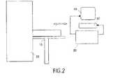
本発明の医療用視検システム及び画像処理方法は、Zuiderveld等のアプローチによって生成した人為的結果を回避することを許容する。ここで、本発明の好適な実施形態を、図2から4までを参照して記載することにする。 The medical inspection system and image processing method of the present invention allows to avoid artifacts generated by the Zuiderveld et al. Approach. A preferred embodiment of the present invention will now be described with reference to FIGS.
図2は、医療用検査装置に組み込まれた、本発明による医療用視検システムの実施形態の基本的な構成要素を示す。図2に概略的に示すように、医療用検査装置は、典型的には、患者が横たわる台10又は撮像装置に対して患者を局所的に配置するための別の要素を含む。医療用撮像装置は、CTスキャナー20であってもよい。CTスキャナー20によって生成した画像データは、汎用のコンピュータのような、データ処理手段30へ供給される。データ処理手段30は、典型的には、モニター40のような視覚化デバイス、及びユーザーによってそのユーザーがそのシステムと情報交換するように稼動するキーボード、ポインティングデバイスなどのような入力デバイス50と関連させられる。要素10−50は、本発明による医療用検査装置を構成する。要素30−50は、本発明による医療用視検システムを構成する。データ処理デバイス30は、本発明の好適な実施形態による医療用画像データを解析する方法を実施するためにプログラムされる。 FIG. 2 shows the basic components of an embodiment of a medical examination system according to the invention incorporated in a medical examination device. As schematically shown in FIG. 2, the medical examination apparatus typically includes a
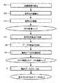
図4Aは、湾曲した解剖学的な面及び関連した臨床データの改善された統合された視覚化を可能とするために、医療用画像データを処理する好適な方法におけるステップを示すフロー図である。 FIG. 4A is a flow diagram illustrating steps in a preferred method of processing medical image data to allow improved integrated visualization of curved anatomical surfaces and associated clinical data. .
その方法に対する画像データの入力は、この例では、主体の心臓に関して得られた3Dコンピュータ断層撮影法の画像データが、その方法に対する画像データの入力である。医療用画像データは、点(ボクセル)に関係する多数のデータからなり、各々の点は、患者の身体内におけるそれぞれの位置に対応する。好適な方法は、
画像データを表示するためのS0(ステップS0において、入力画像データは、例えば雑音を除去するための、従来の前処理を受けてもよい)、
区分された対象の面を算出するためのS1(ステップS1において、心筋の外部表面は、図3Aから3Cまでにおいて区分された湾曲した面RSによって図説されるような区分処理を介して画像データ内から識別される)
のステップをさらに含む。In this example, the image data input to the method is 3D computed tomography image data obtained for the main heart, which is the image data input to the method. Medical image data consists of a large number of data related to points (voxels), each point corresponding to a respective position in the patient's body. The preferred method is
S0 for displaying the image data (in step S0, the input image data may be subjected to conventional preprocessing for removing noise, for example),
S1 for calculating the segmented object plane (in step S1, the external surface of the myocardium is stored in the image data via segmentation as illustrated by the curved surface RS segmented in FIGS. 3A to 3C. Identified from)
These steps are further included.
区分処理において、3Dの面は、定義され、その面は、心筋の外部表面をモデル化する。この3Dの区分された面は、医療用画像データにおける点を互いに結び付けることによって定義された面であってもよく、それらの点は、同じ強度の値、典型的には同じ灰色レベルを有し、よって等価面と呼ばれる。これは、異なる灰色レベルを有する背景に対して、又は別の器官に対して、対象を区分することを許容する。あるいは、この区分された面を、区分の判断基準に応ずる点を互いに結び付けることによって、得てもよい。別の技術においては、3Dの面を、心筋に最高の適合を提供する能動的なモデル又は考慮中の他の解剖学的な対象として得てもよい。またさらに、この3Dの面を、典型的には、図2に示すポインティングデバイス又は他のユーザーの入力デバイス50の操作によって、ユーザーが定義することができる。等価面によって面をモデル化するための技術は、例えば、Academic PressのIsaac N.Bankmanによって編集された“Handbook of Medical Imaging,Processing and Analysing”のJadwiga Rogowskaによる第5章の“Overview and Fundamentals of Medical Image Segmentation”に記載されている。また、解剖学的な対象の能動的なモデルを生成させるための技術は、例えば、International Journal of Computer Vision,32,111−142,1999におけるHerve Delingetteによる“General Object Reconstruction Based on Simplex meshes”と題された発表における記載によって、周知である。 In the segmentation process, a 3D surface is defined that models the external surface of the myocardium. The 3D segmented surface may be a surface defined by connecting points in the medical image data to each other, and the points have the same intensity value, typically the same gray level. Therefore, it is called an equivalent surface. This allows the subject to be segmented against a background with different gray levels or against another organ. Or you may obtain this division | segmentation surface by connecting the points according to the criteria of a division | segmentation mutually. In another technique, a 3D surface may be obtained as an active model that provides the best fit to the myocardium or other anatomical object under consideration. Still further, this 3D surface can be defined by the user, typically by manipulation of the pointing device or other
基準面を算出するためのS2。ステップS2において、区分された対象の面を、3Dの単純化された面をもたらすように、処理し、その単純化された面は、区分された対象の面を近似する。好ましくは、区分された3Dの面を、既知の技術を使用して平滑化して、角又は高度に湾曲した面を取り除く。平滑化された区分された面は、“基準面”と呼ばれ、以下ではRSによって示される。 S2 for calculating the reference plane. In step S2, the segmented object surface is processed to yield a 3D simplified surface, the simplified surface approximating the segmented object surface. Preferably, the segmented 3D surface is smoothed using known techniques to remove corners or highly curved surfaces. The smoothed segmented surface is called the “reference surface” and is denoted by RS in the following.
前記単純化された面を、打ち切りの操作に提出してもよいが、必須ではない。ある実施形態において、この操作は、“基準多面体”と呼ばれる多面体によってしっかりと近似された3Dの面を得ることを許容するが、ここで3Dの単純化された面は、“断片”又は“小面”と呼ばれる、小さい要素に分解されるが、それらの要素は、必ずしも平面ではない。他の実施形態において、基準面RSは、心臓に対して球面又は楕円面、結腸に対して柱面などのような器官の形状の単なる近似でさえあり得る。 The simplified surface may be submitted to the censoring operation, but is not required. In some embodiments, this operation allows to obtain a 3D surface that is closely approximated by a polyhedron called a “reference polyhedron”, where the 3D simplified surface is a “fragment” or “small” Although broken down into smaller elements called “planes”, these elements are not necessarily planar. In other embodiments, the reference plane RS may even be just an approximation of the shape of the organ, such as a spherical or elliptical surface for the heart, a columnar surface for the colon, and the like.
基準多面体を基準面として使用し、平面の小面を示すとすれば、それらの小面に対する法線を算出する。基準多面体を基準面として使用し、断片を示すとすれば、それらの断片に対する法線は、平均の法線によって近似される。基準面RSが、断片も小面もいずれも示さないとすれば、多くの又は全てのボクセルに対する法線が見積もられる。この見積もりは、各々の考慮されたボクセルで接平面を算出することによって、そして、この接平面に対する法線を算出することによって、行われる。3Dの区分された面を近似する、基準多面体における各々の小面又は各々の断片を、それの質量中心の(x,y,z)のデカルト座標によって、小面又は断片に対する外向きの法線ベクトルの成分(u,v,w)によって、及び一組みの隣接した、隣り合う質量中心によって、特徴付けることができる。また、他の実施形態において、単純化された基準面RSの各々のボクセルは、それの(x,y,z)のデカルト座標によって、その点における外向きの近似された法線ベクトルの成分(u,v,w)によって、及び、前記単純化された基準面RSにおける一組みの隣接した点によって、特徴付けられる。基準の選ばれた面の質量中心、節、又は考慮されたボクセルは、以下では、“基準点”と呼ばれる。 If the reference polyhedron is used as a reference surface and plane facets are indicated, normals for those facets are calculated. If the reference polyhedron is used as the reference plane and the fragments are shown, the normals for those fragments are approximated by the average normal. If the reference plane RS shows neither fragments nor facets, normals for many or all voxels can be estimated. This estimation is done by calculating the tangent plane at each considered voxel and by calculating the normal to this tangent plane. Each facet or each fragment in the reference polyhedron approximating a 3D segmented surface is an outward normal to the facet or fragment by its Cartesian coordinate (x, y, z) It can be characterized by the component (u, v, w) of the vector and by a set of adjacent, adjacent mass centers. Also, in other embodiments, each voxel of the simplified reference plane RS is represented by its (x, y, z) Cartesian coordinates with the component of the outward approximated normal vector at that point ( u, v, w) and by a set of adjacent points in the simplified reference plane RS. The center of mass, node, or considered voxel of the selected face of the reference is referred to below as the “reference point”.
三次元の面の区分の技術、及びその面を打ち切るための技術は、周知であり、よって、ここでは詳細に記載しないことにする。区分に関するさらなる情報を、編集長N.Bankman、Academic Pressの“Handbook of Medical Imaging Processing and Analysis”のJadwiga Rogowskaによる第5章の“Overview and Fundamentals of Medical Image Segmentation”に見出すことができる。 Techniques for three-dimensional surface segmentation and techniques for truncating the surface are well known and will therefore not be described in detail here. For further information on the classification, Bankman, Academic Press's “Handbook of Medical Imaging Processing and Analysis” by Jadwiga Rogoska in
距離変換マップを構築するためのS3。ステップS3において、DTによって示される“距離変換面”と呼ばれる面を算出する。これらの面は、基準面RSの距離の変換である。基準面の基準点は、それらの標識のみならず、拡張の操作によって外向きに又は縮小の操作によって内向きに、いずれかに伝達され、一個又は数個の距離変換面DTをもたらし、各々は、基準面RSから与えられた距離内にある。図3Aによって図説するように、外向きの距離変換面DT11及びDT12、並びに、内向きの距離変換面DT21及びDT22は、基準面RSに対応する。各々の距離変換面DTにおける唯一の画像点は、基準面RSの各々の基準点(A、Bなど)に対応する。さらに、各々の距離変換面DTにおける各々の点には、基準面におけるそれの対応する基準点の標識が割り当てられる。図3Bによって図説するように、距離変換面DT11、DT12、DT13における画像点A’、A’’、A’’’は、基準面RSの基準点Aに対応する。これらの画像点A’、A’’、A’’’は、基準点Aにおける基準面RSに対する法線NA上に、及び距離変換面DT11、DT12、DT13に、位置付けられるので、これらの画像点A’、A’’、A’’’が、前記基準面RSからの与えられた所定の距離に位置付けられること、及びこれらの画像点A’、A’’、A’’’が、それぞれ、前記距離変換面DT11、DT12、DT13などにおける前記基準点Aの唯一の対応するものであることが、結果として生じる。S3 for constructing a distance conversion map. In step S3, a surface called “distance conversion surface” indicated by DT is calculated. These planes are conversions of the distance of the reference plane RS. The reference points of the reference plane are transmitted not only to their markers, but either outward by an expansion operation or inward by a reduction operation, resulting in one or several distance conversion surfaces DT, each of which , Within a given distance from the reference plane RS. As illustrated by FIG. 3A, the outward distance conversion surfaces DT11 and DT12 and the inward distance conversion surfaces DT21 and DT22 correspond to the reference surface RS. The only image point on each distance conversion plane DT corresponds to each reference point (A, B, etc.) on the reference plane RS. Furthermore, each point on each distance conversion surface DT is assigned an indicator of its corresponding reference point on the reference surface. As illustrated by FIG. 3B, the image points A ′, A ″, A ′ ″ on the distance conversion surfaces DT11, DT12, DT13 correspond to the reference point A of the reference surface RS. These image points A ', A'', A ''' is on the normal lineN A with respect to the reference surface RS at the reference point A, and the distance transform plane DT 11, DT12, DT13, so positioned, these images The points A ′, A ″, A ′ ″ are positioned at a given distance from the reference plane RS, and these image points A ′, A ″, A ′ ″ are respectively As a result, it is the only corresponding one of the reference points A in the distance conversion surfaces DT11, DT12, DT13, etc.
同様に、基準点Bにおける法線NBは、同じ性質を備えた、距離変換面DT11、DT12における画像点B’、B’’を示す。Similarly, the normalN B at the reference point B, with the same properties, the distance conversion surface DT 11, the image point in DT12 B ', B' indicates a '.
本発明において、臨床データは、基準点A又はBなどと関連して表示されるものである。これらの臨床データは、上述した及び図3Aによって図説したように、異なる距離変換面DTとの交差点における基準面RSに対する法線NA又はNBなどに沿って位置付けられた画像点A’又はB’、A’’又はB’’などの場所で、評価される。よって、本発明は、画像点が、面の法線に沿って位置付けられるだけでなく、異なる距離変換面において、前記距離変換面の構築によって予め決定される基準面RSからの異なる与えられた距離で、位置付けられるので、Zuiderveld等のアプローチから外れている。In the present invention, clinical data is displayed in association with the reference point A or B or the like. These clinical data, as described above and illustrated by FIG. 3A, are image points A ′ or B positioned along normals NA or NB etc. with respect to the reference plane RS at intersections with different distance transformation planes DT. It is evaluated at a location such as', A ″ or B ″. Thus, the present invention not only positions the image points along the normal of the surface, but also at different distance conversion surfaces, different given distances from the reference surface RS predetermined by the construction of the distance conversion surface. Therefore, it is out of the Zuiderveld approach.
本発明の好適な実施形態によれば、画像点は、距離変換面との交差点における基準点毎に対応する面の法線に沿って決定される。よって、距離変換面の画像点は、一義的に、基準面の基準点に対応する。関心のある面に最も近い画像点は、最初に識別され、次に異なる距離変換面における、より遠い及びさらにより遠い画像点が、基準面からできるだけ遠くまで、識別される。好ましくは、画像点は、面の法線及び逆の面の法線の両方に沿って、選択される。前記距離変換面に位置付けられた、関心のある臨床的な面をモデル化する基準面RSの基準点に対応する、異なる識別された画像点は、“データ距離マップ”と呼ばれる点のマップを構成することになり、そのマップは、外向きに及び内向きに基準面を囲む画像点で形成される。 According to a preferred embodiment of the present invention, the image points are determined along the surface normal corresponding to each reference point at the intersection with the distance conversion surface. Therefore, the image point on the distance conversion plane uniquely corresponds to the reference point on the reference plane. The image point closest to the plane of interest is identified first, and then the farther and even farther image points on the different distance transformation planes are identified as far as possible from the reference plane. Preferably, the image points are selected along both the surface normal and the opposite surface normal. The different identified image points corresponding to the reference points of the reference surface RS that model the clinical surface of interest located on the distance conversion surface constitute a map of points called the “data distance map” Thus, the map is formed of image points that surround the reference plane outward and inward.
本発明の主要な利点は、前記“距離マップ”の作成に由来する。マップの性質は、以下のようなものである。マップは、各々の距離変換面において、単一の画像データ点が、基準面の一つの基準点に対応するという事実により、対応する基準点に関する画像点の“一意性”を保証する。マップは、任意の与えられた距離変換面における第一及び第二の画像データの点の相対的な位置が、基準面における対応する第一及び第二の基準点の相対的な位置と同じであるという事実により、“順序の保存”を保証する。 The main advantage of the present invention comes from the creation of the “distance map”. The nature of the map is as follows. The map guarantees the “uniqueness” of the image point with respect to the corresponding reference point due to the fact that at each distance conversion surface, a single image data point corresponds to one reference point of the reference surface. The map is such that the relative positions of the first and second image data points on any given distance transformation plane are the same as the relative positions of the corresponding first and second reference points on the reference plane. The fact that there is guarantees “save order”.
しかしながら、上述の撮像技術をさらに改善するために、さらなる試験を行なってマップの点をより良好に選択してもよい。基準点と関連した臨床データの評価を作るときに好ましくは考慮されることになる画像点を選択するための試験を以下に提案する。提案した試験の中には、
倍率試験(図3Cによって図説される倍率試験と呼ばれる第一の試験を、基準面の基準点と関連した臨床データを評価するときに考慮に入れられる画像データ点の間における(関心のある面に平行な方向における)距離が、ユーザーに定義された比率内に保たれることを保証するために、行なってもよい。例えば、A、Bに対応する、点A’、B’に関して、倍率試験は、A’B’/ABの値をコンピュータで算出すると共に前記値が値の所定の範囲内にあるか否かを見積もるための手段及び試験の役に立たない点を除去するための手段を有する。)、
距離試験(図3Bによって図説される距離試験と呼ばれる第二の試験を、臨床データを評価するときに考慮に入れられる*各々の画像データ点が、基準面の最も近い基準点と関連することを保証するために、行なってもよい。この距離試験は、距離変換面DTが、上述した点を標識する技術のような点を標識する技術なしに作成されるときにのみ、必要とされる。一般に、本発明によれば、それは、基準面からできるだけ遠くに位置決めされた距離変換面にある、基準面に対する法線の点を選択するために、要求される。しかしながら、基準面の与えられた基準点に対応する、最も遠くに見出された画像点を、それ自体の対応する基準点に対するよりも別の基準点に対して近くに位置付けてはならない。例えば、基準点Aに対応する、DT13における画像点A’’’は、それ自体の対応する基準点Aよりも基準点Bに対して近くにあるであろう。距離試験は、このような画像点A’’’を、マップを構築するとき、Bと結合させることができないことを保証する。よって、A’’’は、棄てられる。この試験は、与えられた法線上に選択される最終的な画像点を与える。)
がある。However, further tests may be performed to better select map points in order to further improve the imaging techniques described above. A test is proposed below for selecting image points that will preferably be considered when making an assessment of clinical data associated with a reference point. Among the proposed tests,
A magnification test (a first test, referred to as the magnification test illustrated by FIG. 3C, is performed between the image data points taken into account when evaluating the clinical data associated with the reference point of the reference surface (on the surface of interest This may be done to ensure that the distance (in the parallel direction) is kept within a user defined ratio, eg, magnification test for points A ′, B ′, corresponding to A, B Has a means for computing the value of A'B '/ AB with a computer and estimating whether the value is within a predetermined range of values and means for eliminating points that are not useful for the test. ),
A distance test (a second test, illustrated by the distance test illustrated by FIG. 3B, is taken into account when evaluating the clinical data. * Each image data point is associated with the closest reference point on the reference plane. This distance test is only required when the distance conversion surface DT is created without a technique for marking points, such as the technique for marking points described above. In general, according to the present invention, it is required to select a point normal to the reference plane that lies in a distance conversion plane that is positioned as far as possible from the reference plane. The farthest found image point corresponding to the reference point must not be positioned closer to another reference point than to its own corresponding reference point, eg corresponding to reference point A. DT1 The image point A ′ ″ at will be closer to the reference point B than its own corresponding reference point A. The distance test builds a map of such an image point A ′ ″. (This guarantees that it cannot be combined with B. Thus, A '''is discarded. This test gives the final image point selected on the given normal.)
There is.
距離マップの多くの画像点が、撮像技術を改善するために、棄却されることが必要であると考えられることは、これらの試験の適用から結果として生じる。よって、前記“距離マップ”は、均一な厚さを有しなくてもよいか、又は基準の面の各々の側で同じ厚さを有さなくてもよい。 It arises from the application of these tests that many image points of the distance map are considered to need to be rejected in order to improve the imaging technique. Thus, the “distance map” may not have a uniform thickness, or may not have the same thickness on each side of the reference plane.
第一の三つの性質は、距離マップの構築に対して、前記構築には拡張又は縮小によって構築された距離変換面の各々の点が単一の元来の基準点に対応するので、固有であり、それは、画像点の一意性、画像点の相対的な位置の保存、及び画像点で形成された特徴の形状の保存を保証する。距離マップの使用のおかげで、本発明は、単一のデータ点が、関心のある解剖学的な面における二つの異なる所で視覚化されたデータを生じさせることができないことを保証する。よって、本発明は、関心のある解剖学的な面及び関連した臨床データの統合された表示における不明確さを減少させる。距離マップの使用のおかげで、本発明は、関心のある解剖学的な面と関連して視覚化される、異なる臨床データの項目が、患者の身体におけるこれらのデータ点の真の相対的な位置を反映する、相対的な位置にあることを保証する。提案した倍率試験の役に立たない及び/又は距離試験の役に立たない画像データ点を棄却することによって、本発明の好適な実施形態は、臨床データを視覚化するとき、任意の特徴(例えば、増加した厚さの領域)のみかけの大きさが、過度に誇張されることがない又は過度に最小にされることがないことを保証する。本発明によれば、データ点のマップの使用は、視覚化された画像を不明瞭にする人為的結果を回避することを許容する。 The first three properties are unique to the construction of a distance map because each point of the distance transformation surface constructed by expansion or contraction corresponds to a single original reference point. Yes, it ensures the uniqueness of the image points, the preservation of the relative positions of the image points, and the preservation of the shape of the features formed by the image points. Thanks to the use of distance maps, the present invention ensures that a single data point cannot give rise to data visualized at two different locations in the anatomical plane of interest. Thus, the present invention reduces ambiguity in the integrated display of the anatomical surface of interest and associated clinical data. Thanks to the use of distance maps, the present invention allows different clinical data items, visualized in relation to the anatomical surface of interest, to be the true relative of these data points in the patient's body. Guarantee being in a relative position, reflecting the position. By rejecting image data points that are not useful for the proposed magnification test and / or use for the distance test, the preferred embodiment of the present invention allows any feature (e.g., increased thickness) when visualizing clinical data. To ensure that the apparent size is not overly exaggerated or overly minimized. According to the present invention, the use of a map of data points allows to avoid artifacts that obscure the visualized image.
“距離マップ”の画像点に結び付けられた臨床データを評価するためのS4。本発明いよれば、関心のある面に関係する画像データは、関連した臨床データと統合された様式において表示されるものである。このように、どの臨床データが、関心のある面を近似する、基準面RSのそれぞれの基準点A、BBなどと関連して視覚化されるものであるかを決定することは、必要である。 S4 for evaluating the clinical data associated with the image points of the “distance map”. In accordance with the present invention, image data relating to the surface of interest is displayed in a manner that is integrated with the associated clinical data. Thus, it is necessary to determine which clinical data is to be visualized in relation to each reference point A, BB, etc. of the reference surface RS that approximates the surface of interest. .
表示用の臨床データは、統合された様式で前記データを表示するための支持として選ばれるために、及び上述した技術の一つを使用することによって構築されるために、前記具体的な基準面RS(基準多面体、単純化された面、又は関心のある面を表す任意の他の種類の平滑化された若しくは打ち切られた面)を提供するために描写する面の操作を行う前又は後で、異なって決定される。 Clinical data for display is selected to be used as a support for displaying the data in an integrated manner and to be constructed by using one of the techniques described above. Before or after manipulating the described surface to provide RS (reference polyhedron, simplified surface, or any other type of smoothed or truncated surface representing the surface of interest) , Determined differently.
図4によって図説されるステップ4において、基準面と統合された様式で視覚化される臨床データは、ステップS3で定義された“距離マップ”の選択された画像点の場所で評価される。この評価は、様々な異なる臨床データ、例えば、最小の強度の投射、最大の強度の投射、中間の強度の投射、又は法線に沿った強度の和に対する値を算出することができる。与えられた基準点に対する“最小の強度の投射”の値は、基準点で法線に沿って位置付けられると共にステップS3で定義される“距離マップ”内にある画像点の間における最低の強度の値である。“最大の強度の投射”、“中間の強度の投射”、及び“強度の和”は、説明を要しない。 In
“距離マップ”の画像点の場所で評価される臨床データは、外向きに及び/又は内向きに基準面を包む“関連したデータの距離マップ”をさらに形成する。 The clinical data evaluated at the location of the image points in the “distance map” further forms a “distance map of related data” that wraps the reference plane outward and / or inward.
臨床データのコード化のためのS5。ステップS5において、一度臨床データを“距離マップ”の様々な画像点に対して評価しておくと、算出された値は、関心のある臨床的な面を表示する基準面RSの画像データと統合された様式で視覚化されるために、例えば色のコード値に、コード化される。臨床データを、例えば関心のある面の表示に関する異なる模様、色、又はきめを生成させるコード値を使用して、多種多様な方法でコード化することができる。色のコード化を使用するとすれば、これは、様々なアプローチ、例えば赤色−緑色−青色(RGB)アプローチ又は色相−彩度−明度(HSV)アプローチに追随することができる。本発明は、臨床データを基準面と関連してコード化すると共に視覚化する様式に関わらず、適用可能である。 S5 for encoding clinical data. In step S5, once the clinical data is evaluated for various image points of the “distance map”, the calculated value is integrated with the image data of the reference surface RS that displays the clinical surface of interest. In order to be visualized in a coded manner, for example, it is coded into a color code value. Clinical data can be encoded in a wide variety of ways, for example using code values that produce different patterns, colors, or textures for the display of the surface of interest. If color coding is used, this can follow various approaches, such as a red-green-blue (RGB) approach or a hue-saturation-lightness (HSV) approach. The present invention is applicable regardless of the manner in which clinical data is encoded and visualized in relation to a reference plane.
データを組み合わせるためのS6。次に、ステップS6において、関連したデータの距離マップのコード化された臨床データ及び関心のある解剖学的な面を表示する基準の面の描写された面のデータを組み合わせて、出力される。よって、与えられた法線上の画像点で評価されたコード化された臨床データを、基準面における対応する基準点の場所で画像データと組み合わせる。 S6 for combining data. Next, in step S6, the encoded clinical data of the related data distance map and the rendered surface data of the reference surface displaying the anatomical surface of interest are combined and output. Thus, the coded clinical data evaluated at a given normal image point is combined with the image data at the location of the corresponding reference point in the reference plane.
視覚化のための画像データの出力
一般的に、組み合わせられた出力データは、図2の医療用視検システムのモニター40のような表示デバイスに表示される。評価された臨床データは、時間変動するデータであり得る。例えば、心筋への造影剤の製品の潅流の速さは、臨床的な関心のあるものである。これを、造影剤の製品が心筋に入ると、時間にわたって画像データを集めること、異なる瞬間に心筋を近似する基準面の異なる基準点における法線に沿って最大/最小の強度の投射を評価すること、及び算出された値を色のコード化することによって、表示することができる。ユーザーは、造影剤の製品の潅流を示す色の変化する模様と共に心筋の表示を得ることになる。Output of image data for visualization In general, the combined output data is displayed on a display device such as the
図4Bを参照してさらに記載する好適な実施形態において、その方法は、上で引用したステップ2のサブステップを含む。サブステップS21において、基準面RSが構築される。サブステップS22において、基準点が標識される。サブステップS23において、基準点が、確認される。所定の距離は、関心のある解剖学的な面と関連して視覚化されるデータの分解能を制御する。関心のある臨床データ及び解剖学的な考察(距離が大き過ぎるとすれば、データは、それらが、関心のあるものより他の器官又は解剖学的な特徴に関係するのに対して、過度に考慮されるであろう。)を考慮に入れて限界値を設定してもよい。そして、基準面の各々の基準点は、順々に処理され、基準面に対する法線は、各々の基準点で算出される。 In the preferred embodiment described further with reference to FIG. 4B, the method includes the sub-steps of
次に、ステップS3は、先に記載したように行われる。“距離変換面”DTが構築される。マップを形成する画像点の選択の試験が行われる。上述した試験をする手順の終わりには、妥当な画像データ点の距離マップが、関心のある解剖学的な面をモデル化する基準面に対応して構築されてしまっている。 Next, step S3 is performed as described above. A “distance transformation plane” DT is constructed. A test of the selection of image points forming the map is performed. At the end of the testing procedure described above, a valid image data point distance map has been constructed corresponding to a reference plane that models the anatomical plane of interest.
図4Bを参照して記載した好適な実施形態において、その方法は、上で引用したステップ4のサブステップを含む。サブステップS41において、妥当な画像点の列挙が支給される。サブステップS42において、臨床データが評価される。元来の医療用画像データは、妥当なデータ点の各々で標本抽出される。一般的に、元来の画像データにおけるボクセルの間で内挿を行うことは、画像点の場所が、元来の医療用画像データにおけるボクセルの場所と必ずしも一致しないので、必要である。サブステップS43において、臨床データが位置決めされる。標本抽出されたデータの組みは、関心のある解剖学的な面と統合された様式で視覚化される臨床データを評価するために、基準の3Dの面のそれぞれの点と関連して解析することができる妥当なデータを表す。サブステップS44において、“関連したデータの距離マップ”が形成される。関連したデータの距離マップは、元来の医療用画像データの再フォーマット、例えば画像データの再フォーマットされた体積を表す。 In the preferred embodiment described with reference to FIG. 4B, the method includes the sub-steps of
上記の説明において、臨床データ及び関心のある関連した解剖学的な面を、3Dの形態における統合された様式で視覚化することになることを仮定する。しかしながら、自由選択で、基準の3Dの面を平坦化することができ、対象の界面を、数学的に単純な形態の正則関数w=f(u,v)(例えばB−スプライン)として再フォーマットされた体積にそれを表示することによって、見積もることができ、ここで、wは、基準の3D面までの符号付きの垂直の距離であり、(u,v)は、基準の3D面における座標である。この単純化された表示と連携するとき、標準的なベストフィットの手順を使用することができる。あるいは、又は加えて、平坦化された基準の3Dの面の表示に投射された画像の強度は、それ自体の正面で有用な情報を提供することができる2Dの画像を形成する。例えば、2D画像を、血管の幅若しくは血管の狭窄を解析するために、又は、血管の中心線を決定するために、既知の2D取り扱い技術を使用して処理することができる。 In the above description, it is assumed that clinical data and the relevant anatomical surface of interest will be visualized in an integrated manner in 3D form. However, you can optionally flatten the reference 3D surface and reformat the target interface as a regular function w = f (u, v) (eg B-spline) in a mathematically simple form Can be estimated by displaying it in the measured volume, where w is the signed vertical distance to the reference 3D surface and (u, v) is the coordinate in the reference 3D surface. It is. Standard best-fit procedures can be used when working with this simplified display. Alternatively, or in addition, the intensity of the image projected onto the flattened reference 3D surface display forms a 2D image that can provide useful information in front of itself. For example, 2D images can be processed using known 2D handling techniques to analyze vessel width or vessel stenosis, or to determine vessel centerlines.
上述の好適な実施形態において、3Dの医療用画像データは、コンピュータ断層撮影装置を介して得られた。本発明が、初期データを発生させるために使用される医療用撮像技術に関わらず、適用可能であることは、理解されることである。例えば、心臓を視覚化しようと努めるとき、磁気共鳴(MR)冠状血管撮影法を使用して、非侵襲性の様式で3Dの医療用画像データを発生させてもよい。例えば、Clinical Cardiology,21,323−330,198におけるAchenbach等による“Non−invasive Coronary Angiography by Contrast−Enhanced Electron Beam Computed Tomography”を参照のこと。Achenbach等の論文は、医療用画像データに適用することができる自由選択のデータ処理ステップに関する有用な情報、例えば、他から孤立して、ある一定の解剖学的な特徴の表示を可能とする区分、表示された画像を生成させるために使用されるシェーディング技術の詳細などを含む。これらのステップを、本発明の方法において適用することができる。 In the preferred embodiment described above, 3D medical image data was obtained via a computed tomography apparatus. It should be understood that the present invention is applicable regardless of the medical imaging technique used to generate the initial data. For example, when attempting to visualize the heart, magnetic resonance (MR) coronary angiography may be used to generate 3D medical image data in a non-invasive manner. See, for example, “Non-invasive Coronary Angiography by Contrast-Enhanced Electron Beam Computed Tomography” by Achenbach et al. In Clinical Cardiology, 21, 323-330, 198. The paper by Achenbach et al. Is useful information regarding optional data processing steps that can be applied to medical image data, eg, categories that allow the display of certain anatomical features isolated from others. Including details of the shading technique used to generate the displayed image. These steps can be applied in the method of the present invention.
本発明は、関心のある解剖学的な面をモデル化する方法に関わらず、基準多面体の使用、基準の単体の網目の使用を介したであろうとなかろうと、又はいくつかの他の方法で、適用可能である。好ましくは、関心のある解剖学的な面は、基準面RSを提供する、平滑化のステップが後に続く区分のステップを介して画像データにおいて単に識別されるだけであり、識別された面の具体的なモデル化はない。 Regardless of how the anatomical surface of interest is modeled, the present invention may be through the use of a reference polyhedron, through the use of a reference single mesh, or in some other way. Applicable. Preferably, the anatomical surface of interest is merely identified in the image data via a segmentation step followed by a smoothing step that provides a reference surface RS, and the identification of the identified surface There is no typical modeling.
処理ステップが上述の具体的な実施形態で行われる命令に様々な変更をなすことができる。医療用画像データに適用された上述の処理ステップを、都合よくは、様々な他の既知の処理/視覚化の技術と組み合わせることができる。例えば、画像解析及び視覚化用の基準多面体又は網目によって面をモデル化するとき、小面の大きさを適切に、典型的には小面の大きさが大き過ぎない(大きいものは、不十分な空間分解能を与えるであろう)ように、設定することは、知られている。各々の小面が、対応するボクセルをほとんど又は全く有さない場合を回避することのみならず、同じ理由のために、本発明において小面の大きさのこの適応可能な設定を適用することは、有利であり得る。 Various changes can be made to the processing steps performed in the specific embodiments described above. The above processing steps applied to medical image data can be conveniently combined with various other known processing / visualization techniques. For example, when modeling a surface with a reference polyhedron or mesh for image analysis and visualization, the size of the facet is appropriate, typically the facet size is not too large (larger is not enough It is known to set such that it will give a high spatial resolution). Applying this adaptable setting of facet size in the present invention not only avoids the case where each facet has little or no corresponding voxel, but for the same reason. Can be advantageous.
以上の図面及びそれらの説明は、本発明を限定するというよりもむしろ図説する。添付した請求項の範囲内に属する多数の代わりがあることは、明白であると思われる。この点において以下の結びの言葉がなされる。 The above drawings and their description illustrate rather than limit the invention. It will be apparent that there are numerous alternatives that fall within the scope of the appended claims. In this respect, the following conclusions are made.
さらに、本発明を、表示用の画像データを発生させることに関して記載してきたが、本発明は、表示デバイスにおける表示及び印刷を含むが、それらに限定されない、画像データの実質的に任意の形態の視覚化を包含することが意図されている。請求項におけるいずれの符号も請求項を限定するものと解釈するべきではない。 Further, while the present invention has been described with respect to generating image data for display, the present invention includes substantially any form of image data, including but not limited to display and printing on a display device. It is intended to encompass visualization. Any reference signs in the claims should not be construed as limiting the claim.
Claims (14)
Translated fromJapanese前記画像データを処理し、それによって、前記対象の面を近似する基準面及び前記基準面における基準点を識別し、
前記基準面の基準点に一義的に対応する画像点で形成された、前記基準面から、一個又は数個の距離変換面を含む、距離マップと呼ばれるマップを構築し、
前記マップの前記画像点の場所で臨床データを見積もり、
前記画像データに前記臨床データを統合するように、前記基準点の場所で前記臨床データ及び前記画像データを組み合わせる
処理手段を含み、
当該医療用視検システムは、前記対象の画像及び/又は前記処理された画像を視覚化する画像視覚化手段をさらに含む医療用視検システム。A medical examination system including data acquisition means for acquiring image data in an image of a target surface and processing means for integrating the image data and clinical data,
Processing the image data, thereby identifying a reference surface approximating the surface of interest and a reference point on the reference surface;
Constructing a map called a distance map including one or several distance conversion surfaces from the reference surface, which is formed by image points uniquely corresponding to the reference points of the reference surface,
Estimate clinical data at the location of the image points on the map;
Processing means for combining the clinical data and the image data at the location of the reference point so as to integrate the clinical data into the image data;
The medical inspection system further includes an image visualization means for visualizing the image of the object and / or the processed image.
前記倍率試験の役に立たない前記距離変換面の点を棄てる選択手段
を含む請求項1乃至3のいずれか一項に記載の医療用視検システム。Test means for testing the image points of the distance map, a distance between two image points of a distance conversion surface in a direction parallel to the reference surface between the image points, and a corresponding point of the reference surface 4. A magnification test for estimating whether a ratio to a distance between the two is maintained within a predetermined range; and a selection means for discarding the points on the distance conversion plane that are not useful for the magnification test. The medical inspection system according to one item.
前記距離試験の役に立たない前記面の法線の点を棄てる選択手段
を含む請求項1乃至4のいずれか一項に記載の医療用視検システム。A test means for testing the image points of the distance map; an image point on a normal to the reference plane, positioned on a distance conversion plane in a direction perpendicular to the reference plane between the image points, A distance test to estimate whether it is closest to the corresponding reference point on a surface or closer to another reference point on the reference surface, and a normal point of the surface that is not useful for the distance test The medical inspection system according to any one of claims 1 to 4, comprising selection means for discarding.
前記基準面に対する与えられた法線上の画像点の臨床データを、前記与えられた法線に対応する前記基準点の前記画像データと組み合わせるように、前記基準面の前記対応する基準点の前記画像データと前記関連した距離マップの前記コンピュータで算出された臨床データを組み合わせ、
前記対応する基準点の場所で前記基準面における前記組み合わせられたデータをそれぞれ表示する
処理手段を含む請求項1乃至5のいずれか一項に記載の医療用視検システム。Calculating clinical data at the location of the image points in the distance map by a computer to form a “distance map of related data”;
The image of the corresponding reference point of the reference plane such that clinical data of the image point on a given normal to the reference plane is combined with the image data of the reference point corresponding to the given normal Combining the data and the computer-calculated clinical data of the associated distance map;
The medical inspection system according to any one of claims 1 to 5, further comprising processing means for displaying each of the combined data on the reference plane at the location of the corresponding reference point.
折り曲がった部分が全くない前記対象の面の近似された面を表示する、前記基準面を決定するために前記区分された対象の面のデータを近似し、
前記基準面における基準点を決定し、
前記基準点における前記基準面に対する法線を算出する
処理手段を含む請求項1乃至6のいずれか一項に記載の医療用視検システム。Partitioning the image data, thereby identifying the target surface of the original image;
Displaying the approximated surface of the target surface without any bent portions, approximating the data of the segmented target surface to determine the reference surface;
Determining a reference point on the reference plane;
The medical inspection system according to any one of claims 1 to 6, further comprising processing means for calculating a normal to the reference plane at the reference point.
前記距離変換面の各々の画像点は、基準点に一義的に対応し、前記基準面に対する法線及び距離変換面の交差点に位置付けられる請求項1乃至7のいずれか一項に記載の医療用視検システム。A process of constructing a distance conversion surface from the reference surface by expanding and / or reducing the reference surface to form a map of image points that wraps the reference surface outwardly and / or inwardly as a distance map Including means,
The medical image according to any one of claims 1 to 7, wherein each image point on the distance conversion surface uniquely corresponds to a reference point and is positioned at an intersection of a normal to the reference surface and the distance conversion surface. Inspection system.
前記平滑化された単純化された面の点として前記基準点を識別する
処理手段を含む請求項1乃至8のいずれか一項に記載の医療用視検システム。Constructing the reference surface from the segmented surface as a smoothed and simplified surface;
9. The medical inspection system according to any one of claims 1 to 8, comprising processing means for identifying the reference point as a point on the smoothed and simplified surface.
前記基準面は、複数の小面又は断片を示す請求項9に記載の医療用視検システム。Processing means for constructing the reference surface as a surface truncated from the smoothed and simplified surface;
The medical inspection system according to claim 9, wherein the reference surface indicates a plurality of small surfaces or fragments.
処理は、
前記画像データを処理し、それによって、前記対象の面を近似する基準面及び前記基準面における基準点を識別すること、
前記基準面の基準点に一義的に対応する画像点で形成された、前記基準面から、一個又は数個の距離変換面を含む、距離マップと呼ばれるマップを構築すること、
前記マップの前記画像点の場所で臨床データを見積もること、
前記画像データに前記臨床データを統合するように、前記基準点の場所で前記臨床データ及び前記画像データを組み合わせること、
前記対象の画像及び/又は前記処理された画像を視覚化すること
を含む画像処理方法。12. Image data of a target image of interest is acquired and processed in the data processing means of the medical inspection system according to any one of claims 1 to 11 in order to integrate the image data and clinical data. An image processing method for performing a step of performing
Processing is
Processing the image data, thereby identifying a reference surface approximating the surface of interest and a reference point on the reference surface;
Constructing a map called a distance map including one or several distance conversion surfaces from the reference surface, which is formed by image points uniquely corresponding to the reference points of the reference surface;
Estimating clinical data at the location of the image points of the map;
Combining the clinical data and the image data at the location of the reference point so as to integrate the clinical data into the image data;
An image processing method comprising visualizing the object image and / or the processed image.
Applications Claiming Priority (2)
| Application Number | Priority Date | Filing Date | Title |
|---|---|---|---|
| EP02291263 | 2002-05-22 | ||
| PCT/IB2003/002078WO2003096890A2 (en) | 2002-05-22 | 2003-05-15 | Medical viewing system and image processing for integrated visualisation of medical data |
Publications (2)
| Publication Number | Publication Date |
|---|---|
| JP2005525863Atrue JP2005525863A (en) | 2005-09-02 |
| JP2005525863A5 JP2005525863A5 (en) | 2006-06-29 |
Family
ID=29433210
Family Applications (1)
| Application Number | Title | Priority Date | Filing Date |
|---|---|---|---|
| JP2004504897AWithdrawnJP2005525863A (en) | 2002-05-22 | 2003-05-15 | Medical inspection system and image processing for integrated visualization of medical data |
Country Status (5)
| Country | Link |
|---|---|
| US (1) | US20050163357A1 (en) |
| EP (1) | EP1509124A2 (en) |
| JP (1) | JP2005525863A (en) |
| AU (1) | AU2003230146A1 (en) |
| WO (1) | WO2003096890A2 (en) |
Cited By (1)
| Publication number | Priority date | Publication date | Assignee | Title |
|---|---|---|---|---|
| JP2015531640A (en)* | 2012-09-12 | 2015-11-05 | ノベル バイオケア サーヴィシィズ アーゲー | Digital sprint |
Families Citing this family (9)
| Publication number | Priority date | Publication date | Assignee | Title |
|---|---|---|---|---|
| US7574247B2 (en)* | 2003-11-17 | 2009-08-11 | Siemens Medical Solutions Usa, Inc. | Automatic coronary isolation using a n-MIP ray casting technique |
| TWI235041B (en)* | 2004-12-09 | 2005-07-01 | Univ Tsinghua | Characteristic points automatically identification method for three-dimensional space scanning data of human body |
| US8170304B2 (en)* | 2007-04-03 | 2012-05-01 | Siemens Aktiengesellschaft | Modeling cerebral aneurysms in medical images |
| EP2203894B1 (en)* | 2007-09-03 | 2011-03-02 | Koninklijke Philips Electronics N.V. | Visualization of voxel data |
| CN101441781B (en)* | 2007-11-23 | 2011-02-02 | 鸿富锦精密工业(深圳)有限公司 | Curved surface overturning method |
| JP5491914B2 (en)* | 2009-04-28 | 2014-05-14 | 株式会社東芝 | Image display apparatus and X-ray diagnostic apparatus |
| US8605973B2 (en)* | 2012-03-17 | 2013-12-10 | Sony Corporation | Graph cuts-based interactive segmentation of teeth in 3-D CT volumetric data |
| WO2014084382A1 (en) | 2012-11-30 | 2014-06-05 | 株式会社 東芝 | Medical-image processing device |
| US10765371B2 (en) | 2017-03-31 | 2020-09-08 | Biosense Webster (Israel) Ltd. | Method to project a two dimensional image/photo onto a 3D reconstruction, such as an epicardial view of heart |
Family Cites Families (6)
| Publication number | Priority date | Publication date | Assignee | Title |
|---|---|---|---|---|
| EP0973116A1 (en)* | 1993-03-01 | 2000-01-19 | Kabushiki Kaisha Toshiba | Medical information processing system for supporting diagnosis |
| US5774379A (en)* | 1995-07-21 | 1998-06-30 | The University Of Chicago | System for monitoring an industrial or biological process |
| US5889524A (en)* | 1995-09-11 | 1999-03-30 | University Of Washington | Reconstruction of three-dimensional objects using labeled piecewise smooth subdivision surfaces |
| US5970182A (en)* | 1995-11-15 | 1999-10-19 | Focus Imaging, S. A. | Registration process for myocardial images |
| US5951475A (en)* | 1997-09-25 | 1999-09-14 | International Business Machines Corporation | Methods and apparatus for registering CT-scan data to multiple fluoroscopic images |
| JP2000139917A (en)* | 1998-11-12 | 2000-05-23 | Toshiba Corp | Ultrasound diagnostic equipment |
- 2003
- 2003-05-15USUS10/515,362patent/US20050163357A1/ennot_activeAbandoned
- 2003-05-15EPEP03722989Apatent/EP1509124A2/ennot_activeWithdrawn
- 2003-05-15WOPCT/IB2003/002078patent/WO2003096890A2/enactiveApplication Filing
- 2003-05-15JPJP2004504897Apatent/JP2005525863A/ennot_activeWithdrawn
- 2003-05-15AUAU2003230146Apatent/AU2003230146A1/ennot_activeAbandoned
Cited By (1)
| Publication number | Priority date | Publication date | Assignee | Title |
|---|---|---|---|---|
| JP2015531640A (en)* | 2012-09-12 | 2015-11-05 | ノベル バイオケア サーヴィシィズ アーゲー | Digital sprint |
Also Published As
| Publication number | Publication date |
|---|---|
| AU2003230146A1 (en) | 2003-12-02 |
| WO2003096890A2 (en) | 2003-11-27 |
| EP1509124A2 (en) | 2005-03-02 |
| US20050163357A1 (en) | 2005-07-28 |
| WO2003096890A3 (en) | 2004-06-03 |
| AU2003230146A8 (en) | 2003-12-02 |
Similar Documents
| Publication | Publication Date | Title |
|---|---|---|
| Udupa | Three-dimensional visualization and analysis methodologies: a current perspective | |
| EP3493161B1 (en) | Transfer function determination in medical imaging | |
| US8423124B2 (en) | Method and system for spine visualization in 3D medical images | |
| JP4521271B2 (en) | An image processing system for displaying information on the movement of the top of a deformable three-dimensional object | |
| Alyassin et al. | Evaluation of new algorithms for the interactive measurement of surface area and volume | |
| US7853057B2 (en) | Image processing method and device using a virtual ray and vector information | |
| US7397475B2 (en) | Interactive atlas extracted from volume data | |
| US7920734B2 (en) | Method for visualization of plaque deposits from 3D image data records of vessel structures | |
| CN111563523A (en) | COPD classification using machine trained anomaly detection | |
| Ristovski et al. | Uncertainty in medical visualization: Towards a taxonomy | |
| JP2008510499A (en) | Anatomical visualization / measurement system | |
| US11631177B2 (en) | Machine learning device, estimation device, non-transitory computer readable medium, and learned model | |
| CN116051553B (en) | Method and device for marking inside three-dimensional medical model | |
| EP1851721B1 (en) | A method, a system and a computer program for segmenting a surface in a multidimensional dataset | |
| Udupa | 3D imaging: principles and approaches | |
| JP2005525863A (en) | Medical inspection system and image processing for integrated visualization of medical data | |
| US7684602B2 (en) | Method and system for local visualization for tubular structures | |
| EP3989172A1 (en) | Method for use in generating a computer-based visualization of 3d medical image data | |
| Preim et al. | Visualization, visual analytics and virtual reality in medicine: State-of-the-art Techniques and Applications | |
| Drapikowski | Surface modeling—uncertainty estimation and visualization | |
| US20130114785A1 (en) | Method for the medical imaging of a body part, in particular the hand | |
| US20060103678A1 (en) | Method and system for interactive visualization of locally oriented structures | |
| Kerr et al. | “True” color surface anatomy: mapping the Visible Human to patient-specific CT data | |
| Martadiansyah et al. | 3D Fusion Hierarchical Net Reconstruction from 2D Transcerebellar Images with Deep Learning. | |
| US20250299423A1 (en) | Medical image processing apparatus and method |
Legal Events
| Date | Code | Title | Description |
|---|---|---|---|
| A521 | Request for written amendment filed | Free format text:JAPANESE INTERMEDIATE CODE: A523 Effective date:20060512 | |
| A621 | Written request for application examination | Free format text:JAPANESE INTERMEDIATE CODE: A621 Effective date:20060512 | |
| A761 | Written withdrawal of application | Free format text:JAPANESE INTERMEDIATE CODE: A761 Effective date:20070914 |