JP2005525199A - Dilators for internal routes - Google Patents
Dilators for internal routesDownload PDFInfo
- Publication number
- JP2005525199A JP2005525199AJP2004505148AJP2004505148AJP2005525199AJP 2005525199 AJP2005525199 AJP 2005525199AJP 2004505148 AJP2004505148 AJP 2004505148AJP 2004505148 AJP2004505148 AJP 2004505148AJP 2005525199 AJP2005525199 AJP 2005525199A
- Authority
- JP
- Japan
- Prior art keywords
- balloon
- dilator
- cylindrical portion
- shaft
- diameter
- Prior art date
- Legal status (The legal status is an assumption and is not a legal conclusion. Google has not performed a legal analysis and makes no representation as to the accuracy of the status listed.)
- Pending
Links
- 239000012530fluidSubstances0.000claimsabstractdescription48
- 239000000463materialSubstances0.000claimsabstractdescription13
- 238000004891communicationMethods0.000claimsabstractdescription11
- 230000037361pathwayEffects0.000claimsabstract3
- 210000003679cervix uteriAnatomy0.000claimsdescription22
- 238000000034methodMethods0.000claimsdescription15
- 210000004291uterusAnatomy0.000claimsdescription10
- 230000000916dilatatory effectEffects0.000claimsdescription6
- 210000004204blood vesselAnatomy0.000claimsdescription4
- 230000010339dilationEffects0.000claimsdescription4
- 210000003708urethraAnatomy0.000claimsdescription4
- 239000004952PolyamideSubstances0.000claimsdescription2
- 239000004698PolyethyleneSubstances0.000claimsdescription2
- 229920002647polyamidePolymers0.000claimsdescription2
- -1polyethylenePolymers0.000claimsdescription2
- 229920000573polyethylenePolymers0.000claimsdescription2
- 238000003780insertionMethods0.000description5
- 230000037431insertionEffects0.000description5
- 230000036407painEffects0.000description4
- 206010002091AnaesthesiaDiseases0.000description3
- 230000037005anaesthesiaEffects0.000description3
- 206010000234Abortion spontaneousDiseases0.000description2
- 239000000470constituentSubstances0.000description2
- 208000000995spontaneous abortionDiseases0.000description2
- 241000196324EmbryophytaSpecies0.000description1
- 241000015177Saccharina japonicaSpecies0.000description1
- FAPWRFPIFSIZLT-UHFFFAOYSA-MSodium chlorideChemical compound[Na+].[Cl-]FAPWRFPIFSIZLT-UHFFFAOYSA-M0.000description1
- 238000005452bendingMethods0.000description1
- 230000006378damageEffects0.000description1
- 238000010586diagramMethods0.000description1
- 239000004816latexSubstances0.000description1
- 229920000126latexPolymers0.000description1
- 239000002184metalSubstances0.000description1
- 208000015994miscarriageDiseases0.000description1
- 239000004033plasticSubstances0.000description1
- 229920003023plasticPolymers0.000description1
- 229920002635polyurethanePolymers0.000description1
- 239000004814polyurethaneSubstances0.000description1
- 239000011780sodium chlorideSubstances0.000description1
- 229910001220stainless steelInorganic materials0.000description1
- 239000010935stainless steelSubstances0.000description1
- 238000001356surgical procedureMethods0.000description1
- 230000000451tissue damageEffects0.000description1
- 231100000827tissue damageToxicity0.000description1
- XLYOFNOQVPJJNP-UHFFFAOYSA-NwaterSubstancesOXLYOFNOQVPJJNP-UHFFFAOYSA-N0.000description1
Images


Classifications
- A—HUMAN NECESSITIES
- A61—MEDICAL OR VETERINARY SCIENCE; HYGIENE
- A61M—DEVICES FOR INTRODUCING MEDIA INTO, OR ONTO, THE BODY; DEVICES FOR TRANSDUCING BODY MEDIA OR FOR TAKING MEDIA FROM THE BODY; DEVICES FOR PRODUCING OR ENDING SLEEP OR STUPOR
- A61M25/00—Catheters; Hollow probes
- A61M25/10—Balloon catheters
- A61M25/1027—Making of balloon catheters
- A—HUMAN NECESSITIES
- A61—MEDICAL OR VETERINARY SCIENCE; HYGIENE
- A61M—DEVICES FOR INTRODUCING MEDIA INTO, OR ONTO, THE BODY; DEVICES FOR TRANSDUCING BODY MEDIA OR FOR TAKING MEDIA FROM THE BODY; DEVICES FOR PRODUCING OR ENDING SLEEP OR STUPOR
- A61M29/00—Dilators with or without means for introducing media, e.g. remedies
- A61M29/02—Dilators made of swellable material
- A—HUMAN NECESSITIES
- A61—MEDICAL OR VETERINARY SCIENCE; HYGIENE
- A61M—DEVICES FOR INTRODUCING MEDIA INTO, OR ONTO, THE BODY; DEVICES FOR TRANSDUCING BODY MEDIA OR FOR TAKING MEDIA FROM THE BODY; DEVICES FOR PRODUCING OR ENDING SLEEP OR STUPOR
- A61M25/00—Catheters; Hollow probes
- A61M2025/0001—Catheters; Hollow probes for pressure measurement
- A61M2025/0002—Catheters; Hollow probes for pressure measurement with a pressure sensor at the distal end
- A—HUMAN NECESSITIES
- A61—MEDICAL OR VETERINARY SCIENCE; HYGIENE
- A61M—DEVICES FOR INTRODUCING MEDIA INTO, OR ONTO, THE BODY; DEVICES FOR TRANSDUCING BODY MEDIA OR FOR TAKING MEDIA FROM THE BODY; DEVICES FOR PRODUCING OR ENDING SLEEP OR STUPOR
- A61M2205/00—General characteristics of the apparatus
- A61M2205/33—Controlling, regulating or measuring
- A61M2205/3331—Pressure; Flow
- A—HUMAN NECESSITIES
- A61—MEDICAL OR VETERINARY SCIENCE; HYGIENE
- A61M—DEVICES FOR INTRODUCING MEDIA INTO, OR ONTO, THE BODY; DEVICES FOR TRANSDUCING BODY MEDIA OR FOR TAKING MEDIA FROM THE BODY; DEVICES FOR PRODUCING OR ENDING SLEEP OR STUPOR
- A61M2210/00—Anatomical parts of the body
- A61M2210/10—Trunk
- A61M2210/1078—Urinary tract
- A61M2210/1089—Urethra
- A—HUMAN NECESSITIES
- A61—MEDICAL OR VETERINARY SCIENCE; HYGIENE
- A61M—DEVICES FOR INTRODUCING MEDIA INTO, OR ONTO, THE BODY; DEVICES FOR TRANSDUCING BODY MEDIA OR FOR TAKING MEDIA FROM THE BODY; DEVICES FOR PRODUCING OR ENDING SLEEP OR STUPOR
- A61M2210/00—Anatomical parts of the body
- A61M2210/12—Blood circulatory system
- A—HUMAN NECESSITIES
- A61—MEDICAL OR VETERINARY SCIENCE; HYGIENE
- A61M—DEVICES FOR INTRODUCING MEDIA INTO, OR ONTO, THE BODY; DEVICES FOR TRANSDUCING BODY MEDIA OR FOR TAKING MEDIA FROM THE BODY; DEVICES FOR PRODUCING OR ENDING SLEEP OR STUPOR
- A61M2210/00—Anatomical parts of the body
- A61M2210/14—Female reproductive, genital organs
- A61M2210/1433—Uterus
Landscapes
- Health & Medical Sciences (AREA)
- Heart & Thoracic Surgery (AREA)
- Life Sciences & Earth Sciences (AREA)
- General Health & Medical Sciences (AREA)
- Veterinary Medicine (AREA)
- Public Health (AREA)
- Engineering & Computer Science (AREA)
- Anesthesiology (AREA)
- Biomedical Technology (AREA)
- Hematology (AREA)
- Animal Behavior & Ethology (AREA)
- Pulmonology (AREA)
- Biophysics (AREA)
- Child & Adolescent Psychology (AREA)
- Vascular Medicine (AREA)
- Media Introduction/Drainage Providing Device (AREA)
- External Artificial Organs (AREA)
- Dental Tools And Instruments Or Auxiliary Dental Instruments (AREA)
- Surgical Instruments (AREA)
- Materials For Medical Uses (AREA)
- Thermotherapy And Cooling Therapy Devices (AREA)
- Inorganic Insulating Materials (AREA)
- Percussion Or Vibration Massage (AREA)
Abstract
Translated fromJapaneseDescription
Translated fromJapanese本発明は、医療器具に係わり、より詳しくは、体内経路を拡張するための拡張器に関するものである。 The present invention relates to medical devices, and more particularly to a dilator for dilating a body passage.
体内経路、例えば血管、尿道、頚部等の拡張を要することがしばしばある。例えば頚部の場合、医療処置時に子宮腔内へ外科器具を挿入可能にするために頚部の拡張を要することがある。該医療処置には、流産の処理、自然流産の成就処置、手術時の子宮鏡検査が含まれる。
ヒトの子宮頚部は、長さ2〜5cmの管状構造物である。この頚部は、通常は閉じられているが、直径2〜3mmのカテーテルなら、麻酔なしで女性患者に僅かの苦痛を与えるだけで頚部内へ挿入できる。通常は、10〜12mm直径まで頚部を拡張する必要がある。
頚部拡張の公知の一方法は、ヘーガル(Hegar)拡張器を使用するものである。該拡張器は、実質的には金属ロッドである。比較的小口径の拡張器を頚部内へ挿入して、先ず少し拡張する。次いで、そのロッドを除去して、より僅かに口径の大きいロッドを頚部内へ挿入する。次いで、このロッドを除去して、この処置を反復し、その度に口径のより大きいロッドを挿入し、目標の拡張が達せられるまで続ける。この処置は、ある形式の麻酔を必要とし、また頚部を傷つける恐れもある。Often it is necessary to dilate body routes such as blood vessels, urethra, cervix. For example, in the case of the cervix, it may be necessary to expand the cervix to allow insertion of surgical instruments into the uterine cavity during medical procedures. The medical procedures include miscarriage processing, spontaneous abortion treatment, and hysteroscopy at the time of surgery.
The human cervix is a 2-5 cm long tubular structure. The neck is normally closed, but a catheter with a diameter of 2 to 3 mm can be inserted into the neck without any anesthesia and with slight pain to the female patient. Usually, it is necessary to expand the neck to a diameter of 10-12 mm.
One known method of cervical dilation is to use a Hegar dilator. The dilator is substantially a metal rod. A dilator with a relatively small diameter is inserted into the cervix and first expanded slightly. The rod is then removed and a slightly larger diameter rod is inserted into the neck. The rod is then removed and the procedure is repeated, each time a larger caliber rod is inserted, continuing until the target expansion is achieved. This procedure requires some form of anesthesia and can also damage the neck.
スタブス(Stubbs)による米国特許第4,624,258号には、マコンブ(Laminaria japonica)の植物茎を内包する挿入体を含む感湿式拡張器が開示されている。この場合、挿入体が先ず頚部内へ挿入されると、マコンブが頚部内の水分を吸収して膨張する結果、頚部が拡張される。
また、WO81/01098には、膨張可能なラテックスバルーンを含む頚部拡張器が開示されている。このバルーンは、高圧に耐えられるように非弾性的な材料で形成されたスリーブ内に収容されている。
レイニンジャー(Leininger)による米国特許第4,137,222号には、端部に球根状の拡大部を備えた膨張可能なバルーンを有する膨張可能な拡張器が開示されている。バルーンを膨張させると、拡大部が子宮内で拡張する一方、バルーンの残りの部分が頚部内で膨張する。U.S. Pat. No. 4,624,258 to Stubbs discloses a wet-sensitive dilator that includes an insert that encloses the plant stem of Laminaria japonica. In this case, when the insert is first inserted into the cervix, the macombu absorbs moisture in the cervix and expands, resulting in expansion of the cervix.
WO81 / 01098 also discloses a cervical dilator including an inflatable latex balloon. The balloon is housed in a sleeve made of an inelastic material so that it can withstand high pressure.
U.S. Pat. No. 4,137,222 to Leininger discloses an inflatable dilator having an inflatable balloon with a bulbous enlargement at the end. When the balloon is inflated, the enlarged portion expands in the uterus, while the remaining portion of the balloon expands in the cervix.
本発明は、体内経路拡張する拡張器と拡張方法とを提供するものである。拡張器は、子宮頚部の拡張と関連して説明されるが、本発明の拡張器は、他の体腔、例えば尿道又は血管に使用することもできる。
本発明の拡張器は、遠位端と近位端とを有する中空の軸を含んでいる。該軸は、通常、約1〜2mmの直径を有している。軸の遠位端には膨張可能なバルーンが備えられている。軸の内腔内には近位端から遠位端へ向かって加圧流体が流され、バルーンを膨張させる。
バルーンは、可とう性の実質的に伸長不能な材料で形成される。バルーン材料は、また更に膨張したバルーンが最大10バール、より好ましくは20バール、更に好ましくは30バールの圧力に耐え得るように選択される。バルーン壁部は、バルーンが軸上に収縮した状態でのバルーン直径が、膨張時のバルーン円筒部直径の最大35%、より好ましくは30%、更に好ましくは25%となるように、十分に薄手に選定される。バルーン壁部の厚さは、好ましくは0.1mm未満、より好ましくは0.08mm未満、更に好ましくはほぼ0.05mmである。The present invention provides a dilator and a dilation method for dilating a body passage. Although the dilator is described in connection with cervical dilation, the dilator of the present invention can also be used in other body cavities, such as the urethra or blood vessels.
The dilator of the present invention includes a hollow shaft having a distal end and a proximal end. The shaft typically has a diameter of about 1-2 mm. An inflatable balloon is provided at the distal end of the shaft. Within the shaft lumen, pressurized fluid is flowed from the proximal end to the distal end to inflate the balloon.
The balloon is formed of a flexible, substantially non-stretchable material. The balloon material is also selected so that the further inflated balloon can withstand a pressure of up to 10 bar, more preferably 20 bar, more preferably 30 bar. The balloon wall is sufficiently thin so that the balloon diameter when the balloon is deflated on the axis is a maximum of 35%, more preferably 30%, and even more preferably 25% of the diameter of the balloon cylinder when inflated. Selected. The thickness of the balloon wall is preferably less than 0.1 mm, more preferably less than 0.08 mm, and even more preferably approximately 0.05 mm.
例えば、本発明人は、ポリエチレン・ペレフタレート(PET)及びポリアミド製で膨張時直径12mm、壁厚0.05mmの円筒形バルーンが、少なくとも最大14バールの圧力に耐え得ることを発見した。円筒形バルーンが耐え得る最大圧力はバルーン壁厚に比例し、前記の材料製で、壁厚0.10mmを有する膨張時直径のバルーンは、最大28バールの圧力に耐えられる。同じように、前記の材料製で、壁厚0.20mmを有する膨張時直径のバルーンは、最大42バールの圧力に耐えられる。最大10mmの膨張時直径と最大0.2mmの壁圧とを有する円筒形バルーンは、1mm直径の軸上に収縮した状態では、直径が3mm未満となろう。 For example, the present inventor has discovered that a cylindrical balloon made of polyethylene perephthalate (PET) and polyamide and having a diameter of 12 mm when inflated and a wall thickness of 0.05 mm can withstand pressures of at least up to 14 bar. The maximum pressure that a cylindrical balloon can withstand is proportional to the balloon wall thickness, and an inflated diameter balloon made of the aforementioned material and having a wall thickness of 0.10 mm can withstand a pressure of up to 28 bar. Similarly, an inflated diameter balloon made of the aforementioned material and having a wall thickness of 0.20 mm can withstand pressures up to 42 bar. A cylindrical balloon with an inflated diameter of up to 10 mm and a wall pressure of up to 0.2 mm will be less than 3 mm in diameter when deflated on a 1 mm diameter axis.
バルーンは、円筒形部分より大きい直径を有する膨張バルーンの遠位端に球形のふくらみを有するように、任意に形成することができる。あるいはまた、拡張器は、円筒形バルーンと、別個の球形または長円形のバルーンとを含むことができる。遠位に球形バルーンを設けることにより、バルーンの円筒形部分を、詳しく後述するように、頚部内に正しく位置決めできる。更に、球形バルーンは、等しい材料、等しい壁厚の円筒形バルーンに比して、2倍の圧力に耐えることができる。したがって、一実施例では、拡張器は、経路の一部を拡張するために使用される球形バルーンを含んでいる。
軸の近位端は、加圧流体源に接続されるようにされている。該加圧流体は、好ましくは非圧縮性流体、例えば水又は食塩水である。該流体は、軸の近位端から遠位端へ、ひいてはバルーン内へ流体の加圧によって送入される。例えば、流体は、軸の内腔と流体連通するように配置されたシリンジに注入される。流体は、次いでシリンジのピストンを押し込むことで手動式に加圧される。The balloon can optionally be formed to have a spherical bulge at the distal end of an inflation balloon having a larger diameter than the cylindrical portion. Alternatively, the dilator can include a cylindrical balloon and a separate spherical or oval balloon. By providing a distal spherical balloon, the cylindrical portion of the balloon can be properly positioned within the neck, as described in detail below. Furthermore, spherical balloons can withstand twice as much pressure as cylindrical balloons of equal material and wall thickness. Thus, in one embodiment, the dilator includes a spherical balloon that is used to dilate a portion of the path.
The proximal end of the shaft is adapted to be connected to a pressurized fluid source. The pressurized fluid is preferably an incompressible fluid, such as water or saline. The fluid is pumped from the proximal end to the distal end of the shaft and thus into the balloon by fluid pressurization. For example, fluid is injected into a syringe that is placed in fluid communication with the lumen of the shaft. The fluid is then pressurized manually by pushing the piston of the syringe.
一好適実施形式では、流体は、電動ポンプにより加圧され、該電動ポンプにより、予め決められた流量でバルーンへ軸を介して送られる。流測は、患者に苦痛を与えることのない速度でバルーンが膨張するように十分に遅く選択する。拡張器はしたがって、患者に麻酔をすることなしに使用できる。
バルーンは非伸長性材料製なので、非圧縮性流体がバルーンの膨張に使用される場合、バルーンの体積は、バルーンへ送られる流体量によって、いつでも決められる。特に、バルーンの最大体積は、該体積の流体がバルーンへ送られた場合に得られる。In one preferred embodiment, the fluid is pressurized by an electric pump and is pumped through the shaft to the balloon at a predetermined flow rate. The flow meter is chosen sufficiently slow so that the balloon is inflated at a rate that does not cause pain to the patient. The dilator can therefore be used without anesthetizing the patient.
Because the balloon is made of a non-extensible material, when an incompressible fluid is used to inflate the balloon, the balloon volume is always determined by the amount of fluid delivered to the balloon. In particular, the maximum volume of the balloon is obtained when that volume of fluid is delivered to the balloon.
したがって、本発明の第一態様により、体内経路を拡張するための次のような拡張器が得られる。すなわち、
(a)内腔と、近位端と、遠位端とを有する細長の中空軸と、
(b)該中空軸の内腔と流体連通する、中空軸遠位端のバルーンとを含む拡張器において、該バルーンが少なくとも1つの円筒部を有する形式のものにおいて、
(i)前記バルーンが、少なくとも10バールの膨張圧に耐えることのできる可とう性の非伸長性材料で形成され、
(ii)前記バルーンが非膨張状態で軸上に収縮した状態の場合、軸上でのバルーン直径が、膨張状態での円筒部直径の最大35%であることを特徴とする拡張器である。Therefore, according to the first aspect of the present invention, the following dilator for dilating the body passage is obtained. That is,
(A) an elongated hollow shaft having a lumen, a proximal end, and a distal end;
(B) a dilator comprising a hollow shaft distal end balloon in fluid communication with the hollow shaft lumen, wherein the balloon has at least one cylindrical portion;
(I) the balloon is formed of a flexible non-extensible material capable of withstanding an inflation pressure of at least 10 bar;
(Ii) An expander characterized in that when the balloon is in a non-expanded state and contracted on the shaft, the diameter of the balloon on the shaft is a maximum of 35% of the diameter of the cylindrical portion in the expanded state.
本発明の第2態様によれば、体内経路を拡張する方法が得られ、該方法は、本発明による拡張器のバルーンの円筒形部分を経路内へ挿入し、バルーンを膨張させる段階を含んでいる。
本発明を理解し、本発明がどのように実施されるかを知るために、以下で好適一実施例を添付図面につき説明するが、該実施例は、本発明を制限するものではない。According to a second aspect of the present invention, a method for dilating a body passage is obtained, the method comprising the steps of inserting a cylindrical portion of a balloon of a dilator according to the present invention into the passage and inflating the balloon. Yes.
In order to understand the present invention and to know how it can be implemented, a preferred embodiment will be described below with reference to the accompanying drawings, which do not limit the invention.
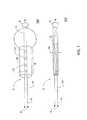
図1は、本発明の一実施例による体内経路を拡張するための拡張器を示している。全体を符号2で示されたこの拡張器は、近位端6と遠位端8とを有する細長の軸4を含んでいる。軸4は、1〜2mmの外径を有し、内腔10を取り囲んでいる。該軸は、曲げ弾性を有する材料、例えばプラスチック、ステンレス鋼、ポリウレタンで形成されている。軸4の遠位端8に設けられた丸いキャップ5は、挿入時の組織損傷を防止する。
軸4の遠位端に配置された膨張可能なバルーン12は、実質的に非伸長性の可とう性材料で形成されている。バルーン12は、図1aに膨張状態で示されている。膨張したバルーン12は、概して円筒形の部分9を有し、該円筒形部分は、長さ約6cm、膨張状態での直径約1.2cmである。この円筒形部分は、軸と同軸線的であり、円形横断面を有している。バルーンは、軸4の軸線に対して直角の約15mmの軸線を有する長円形部分11 で終わっている。FIG. 1 illustrates a dilator for dilating a body passage according to one embodiment of the present invention. This dilator, generally designated 2, includes an elongate shaft 4 having a proximal end 6 and a distal end 8. The shaft 4 has an outer diameter of 1 to 2 mm and surrounds the
The
図1bは、非膨張状態でのバルーン12を有する拡張器を示している。バルーン12は、収縮状態で軸4の周囲を包んでいる。バルーン12の壁部は約0.02−0.05mmの厚さを有しているから、軸11上の収縮バルーンの直径14は3mm未満である。
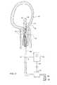
バルーン12は、軸4上に収縮した非膨張状態で、拡張を要する経路へ挿入される。図2は、バルーンが非膨張状態で子宮頚部16に挿入された後の拡張器を示している。遠位端8と長円形部分11とは、子宮24内に位置している。電動ポンプ18が、リザーバ22内の非圧縮性流体20をバルーン12内へ送入するのに使用される。流体は、ポンプ18から、軸4の内腔10と軸4の遠位端の開口17とを経て、バルーン12内へ流入する。ポンプ18は、麻酔なしで患者に過剰な苦痛を与えないように、十分にゆっくりとバルーン12内の圧力を上昇させる流量で流体を送入するようプログラム可能である。FIG. 1b shows the dilator having the
The
あるいはまた、ポンプ18の流量は、流量セレクタ19により選択可能である。流量セレクタ19は、ポンプ18から離れた位置に配置し、例えばケーブル21又は遠隔制御装置(図示せず)により操作できる。離れて配置可能な流量セレクタ19は、患者が制御でき、これにより患者は過剰な苦痛を覚えない流量を選択できる。ポンプ18は、膨張中にバルーン12の内の流体圧を測定する圧力計3に接続されている。この場合、ポンプ18は、予め決められた圧力増大が達せられるように、バルーン12への流体送入をプログラム化できる。ポンプ18は、更に、バルーン12へ送入される流体20の量がバルーン4の最大容量に等しくなると、バルーンへの流体20の送入を中止するようにプログラム化できる。
バルーン12が膨張するさい、バルーン12の円筒形部分と長円形部分との壁厚は等しいのに、バルーンの長円形部分11が円筒形部分9より先に膨張する。これは、子宮24内に位置する長円形部分11の外部圧力が、頚部16内の円筒形部分11の外部圧力より小さいからである。Alternatively, the flow rate of the
When the
図3には、バルーン12が部分的に膨張した状態の拡張器が示され、長円形部分11は、ほとんど完全に膨張し、円筒形部分9は一部分だけが膨張している。この時点で、バルーン12は、矢印23の方向で近位へ移動させられ、それにより長円形部分11が内子宮口25のところに留められる。これによって、確実に円筒形部分9がほぼ頚部内に位置せしめられる。バルーン12の膨張は、バルーン12が最大体積になるまで続けられ、最大体積になると、円筒形部分9が完全に広げられ、少なくとも10cm、好ましくは12cmの直径となる。頚部16が完全に拡張されると、バルーン内圧は、10バールを超え、20バール、30バール、40バールのいずれかとなる。図4は、バルーン4が完全に膨張し、バルーン4の長円形部分11が内子宮口25に留まっている状態の拡張器2を示している。バルーン12は、ここで流体を抜かれ、拡張器2が体内から引き出される。 FIG. 3 shows the dilator with the
図5は、全体を符号35で示された、本発明の拡張器の別の実施例を示している。拡張器35は、拡張器2と共通の特徴を有しているので、類似の構成部材には等しい符号を付し、改めて説明はしない。実施例35は、2個のバルーン36,37を有し、図5には、これらが膨張状態で示されている。バルーン36は、膨張状態では円筒形を有し、バルーン12の円筒形部分9と類似の寸法を有しているバルーン37は、長円形を有し、バルーン12の長円形部分11と類似の寸法を有している。拡張器35は、図2〜図4の拡張器2と同じように使用される。両バルーン36,37は、軸11と流体連通している。バルーン12の長円形部分11に関して既に述べたように、長円形バルーン37は、円筒形バルーン36より先に膨張する。長円形バルーン37が膨張すると、軸4は、長円形バルーン37が内子宮口に留まるまで、近位へ移動せしめられる。軸4は、2つのバルーン36,37の間隔にほぼ等しい距離だけ、軸に沿って遠位に移動せしめられ、これにより円筒形バルーン36が頚部内に位置決めされる。 FIG. 5 shows another embodiment of the dilator of the present invention, indicated generally at 35. Since the
図6には、本発明の拡張器の別の実施例が示され、符号45で全体が示されている。拡張器45は、拡張器35と共通の特徴を有しているので、類似の構成部材には等しい符号を付してあり、説明は省略する。特に、実施例45は、2個のバルーン36,37を有し、これらのバルーンが、図6には膨張状態で示されている。バルーン36は、膨張状態では円筒形になり、バルーン12の円筒形部分9と類似の寸法を有している。バルーン37は、長円形であり、バルーン12の長円形部分11と類似の寸法を有している。拡張器35と異なり、拡張器45は、第1内腔47と第2内腔48とを有する軸46を備えている。第1内腔47は、近位端49と、円筒形バルーン36内に位置する遠位端50とを有している。流体は、内腔47から、軸46の開口17aを経て円筒形バルーン36内へ送られる。内腔48は、近位端53と、球形バルーン36の遠位に位置する遠位端51とを有している。流体は、内腔48から軸46の開口17bを経て球形バルーン37内へ送られる。内腔47,48の各々は、ポンプ18とリザーバ20(図2〜図4に示すように)とに接続されているので、バルーン36,37は別個に膨張可能である。拡張器45は、図2〜図4に示した拡張器2と同じように使用される。特に、長円形バルーン37は、遠位端バルーン36より先に膨張できる。このことは、図5と関連して説明したように、頚部内での円筒形バルーン36の位置決めのために行われる。 FIG. 6 shows another embodiment of the dilator of the present invention, indicated generally by the numeral 45. Since the
図7は、本発明の拡張器の別の実施例を示すもので、全体が符号55で示されている。拡張器55は、図6の拡張器45と共通の特徴を有しているので、類似の構成部品には等しい符号を付し、説明は省略する。実施例55は、2個のバルーン36,57を有し、該バルーンが、図7aには膨張状態で、図7bには非膨張状態で示されている。バルーン36は、膨張時には円筒形となり、バルーン12の円筒形部分9と類似の寸法を有している。バルーン57は、膨張時には長円形となり、バルーン12bの長円形部分11に似た膨張寸法を有している。バルーン57は、非膨張時には、弾性的括着部位54のところで軸46の周囲に括着(押え付け)されて、非膨張状態のバルーン57には2つの別個の膨張可能な区画が形成される。詳しくは後述するが、内腔48内の加圧流体は遠位の区画56へのみ送入される。遠位区画内の流体圧が予め定めた値を超えると、流体は、詳しくは後述するように、遠位区画56から近位区画58内へ流入するよう強制される。 FIG. 7 shows another embodiment of the dilator of the present invention, which is indicated generally by the
図8は、拡張器55を装着した図である。図8に示すように、バルーン36は、子宮頚部16内へ、またバルーン57は子宮24内へ、それぞれ非膨張状態で軸46上に収縮された状態で挿入される。次いで、流体が、軸46の内腔48と開口17bとを経てバルーン57の遠位区画56内へ、図9に示すように、遠位区画56の膨張が完了するまで、注入される。弾性的な括着(押え付け)区域54のため、バルーン57の近位区画58は、この時点では膨張しない。膨張した遠位区画56は、内子宮口25に留まり、これにより円筒形バルーン36が正確に子宮頚部16内に位置決めされる。近位区画58は、いまや頚部16の遠位端内に位置せしめられる。ここで加圧流体が、軸46の内腔48を介して円筒形バルーン内へ送入される。 FIG. 8 is a diagram in which the
図10は、円筒形バルーン36が膨張を完了した後の拡張器55を示している。ここで、追加流体が長円形バルーンの遠位区画56へ送入される。遠位区画56内の流体圧力が予め定めた閾値を超えると、弾性的な括着区域54が拡張されて近位区画内への流体の流入が可能になる、図11には、バルーン57が完全に膨張した状態での拡張器が示されている。近位区画58が膨張することにより、頚部16の遠位端部分が拡開される。球形バルーンは、等しい材料、等しい壁厚の円筒形バルーンの2倍の圧力に耐えられる。したがって、球形バルーンは、円筒形バルーンにより頚部に与えられる圧力の約2倍の圧力を、頚部の遠位端部分(この部分が拡開抵抗が最大)に加えることができる。 FIG. 10 shows the
2 第1実施例の拡張器
4 軸
6 近位端
8 遠位端
9 円筒形部分
10 内腔
11 長円形部分
12 膨張可能なバルーン
14 収縮状態でのバルーン直径
16 子宮頚部
17 軸の開口
18 電動ポンプ
19 流量セレクタ
20 流体
21 ケーブル
22 リザーバ
24 子宮
25 内子宮口
35 第2実施例による拡張器
36 円筒形バルーン
37 長円形バルーン
45 第3実施例による拡張器
46 軸
47 第1内腔
48 第2内腔
49 第1内腔の近位端
50 第1内腔の遠位端
51 第2内腔の遠位端
53 第2内腔の近位端
54 括着部位
55 第4実施例による拡張器
56 遠位区画
57 バルーン
58 近位区画2 Dilator of the first embodiment 4 Axis 6 Proximal end 8 Distal end 9
Claims (31)
Translated fromJapanese(c)内腔と、近位端と、遠位端とを有する細長の中空軸と、
(d)前記軸の内腔に流体連通する前記軸遠位端のバルーンとを含み、該バルーンが少なくとも1つの円筒形部分を有する形式のものにおいて、
(i)前記バルーンが、少なくとも10バールの膨張圧に耐えられる可とう性の非伸長性材料で形成され、
(iii)非膨張状態の前記バルーンを軸上に収縮させた場合、軸上でのバルーン直径が、膨張円筒形部分の直径の最大35%であることを特徴とする、体内経路を拡張する拡張器。A dilator that expands the body passageway,
(C) an elongated hollow shaft having a lumen, a proximal end, and a distal end;
(D) a balloon at the distal end of the shaft in fluid communication with a lumen of the shaft, the balloon having at least one cylindrical portion;
(I) the balloon is formed of a flexible non-extensible material capable of withstanding an inflation pressure of at least 10 bar;
(Iii) dilatation for expanding a body passage, characterized in that when the non-inflated balloon is deflated on the shaft, the balloon diameter on the shaft is up to 35% of the diameter of the inflated cylindrical portion vessel.
Applications Claiming Priority (2)
| Application Number | Priority Date | Filing Date | Title |
|---|---|---|---|
| IL14968702AIL149687A0 (en) | 2002-05-15 | 2002-05-15 | Cervical dilator |
| PCT/IL2003/000400WO2003097154A1 (en) | 2002-05-15 | 2003-05-15 | Dilator for body passageway |
Publications (1)
| Publication Number | Publication Date |
|---|---|
| JP2005525199Atrue JP2005525199A (en) | 2005-08-25 |
Family
ID=28460411
Family Applications (1)
| Application Number | Title | Priority Date | Filing Date |
|---|---|---|---|
| JP2004505148APendingJP2005525199A (en) | 2002-05-15 | 2003-05-15 | Dilators for internal routes |
Country Status (9)
| Country | Link |
|---|---|
| US (1) | US20060178692A1 (en) |
| EP (1) | EP1507571B1 (en) |
| JP (1) | JP2005525199A (en) |
| AT (1) | ATE350091T1 (en) |
| AU (1) | AU2003224416A1 (en) |
| DE (1) | DE60310918D1 (en) |
| IL (1) | IL149687A0 (en) |
| RU (1) | RU2004136598A (en) |
| WO (1) | WO2003097154A1 (en) |
Cited By (1)
| Publication number | Priority date | Publication date | Assignee | Title |
|---|---|---|---|---|
| JP2010516351A (en)* | 2007-01-25 | 2010-05-20 | レベル・スリー・イノベイションズ・プロプライエタリー・リミテッド | Tube expansion device |
Families Citing this family (12)
| Publication number | Priority date | Publication date | Assignee | Title |
|---|---|---|---|---|
| BRPI0806361B8 (en)* | 2007-02-09 | 2021-06-22 | B & D Medical Dev Llc | device for controlling genecological and obstetric bleeding in a patient's body cavity, and kit |
| US9364638B2 (en)* | 2014-01-21 | 2016-06-14 | Cook Medical Technologies Llc | Adjustable vaginal anchor for uterine tamponade device and methods of using the same |
| CN104107497B (en)* | 2014-07-09 | 2016-08-24 | 河南科技大学第一附属医院 | One cervical auxiliary expander |
| CN104107498B (en)* | 2014-07-09 | 2016-08-24 | 河南科技大学第一附属医院 | One cervical auxiliary expanding equipment |
| CN105233396B (en)* | 2015-11-13 | 2019-01-15 | 河南埃纳生医疗科技有限公司 | Disposable vertebra shape bellows cervical dilator |
| WO2017214381A1 (en) | 2016-06-09 | 2017-12-14 | Conmed Corporation | Uterine manipulator |
| US20180021064A1 (en)* | 2016-07-22 | 2018-01-25 | Zhejiang Shanshi Biological Medical (Shangqiu) Co., Ltd. | Suction Tube for Abortion and Using Method Thereof |
| US10617313B2 (en)* | 2016-08-22 | 2020-04-14 | Clinical Innovations, Llc | Pressure catheter device |
| US10695092B2 (en) | 2018-02-20 | 2020-06-30 | Conmed Corporation | Uterine manipulator |
| AU2022328709A1 (en)* | 2021-08-18 | 2024-01-25 | Celestial Life Sciences, Llc | Cervical dilator |
| US11849971B1 (en)* | 2022-11-28 | 2023-12-26 | Nemow Llc | Uterine toner device to prevent and control postpartum hemorrhage |
| WO2025080754A1 (en)* | 2023-10-11 | 2025-04-17 | Celestial Life Sciences, Llc | Cervical dilators and methods of use therefor |
Family Cites Families (17)
| Publication number | Priority date | Publication date | Assignee | Title |
|---|---|---|---|---|
| US3900033A (en)* | 1973-03-07 | 1975-08-19 | Ortho Pharma Corp | Dilator for cervical canal |
| FR2267115B1 (en)* | 1974-04-12 | 1977-11-10 | Merieux Inst | |
| US4624258A (en)* | 1984-09-11 | 1986-11-25 | Milex Products, Incorporated | Cervical dilator with captive extraction element |
| US5312430A (en)* | 1986-12-09 | 1994-05-17 | Rosenbluth Robert F | Balloon dilation catheter |
| EP0274411A3 (en)* | 1987-01-09 | 1988-11-30 | C.R. Bard, Inc. | Thin wall high strength balloon and method of manufacture |
| US5304197A (en)* | 1988-10-04 | 1994-04-19 | Cordis Corporation | Balloons for medical devices and fabrication thereof |
| US5152776A (en)* | 1990-04-03 | 1992-10-06 | Cordis Corporation | Balloon inflation device |
| US5348538A (en)* | 1992-09-29 | 1994-09-20 | Scimed Life Systems, Inc. | Shrinking balloon catheter having nonlinear or hybrid compliance curve |
| US6120523A (en)* | 1994-02-24 | 2000-09-19 | Radiance Medical Systems, Inc. | Focalized intraluminal balloons |
| US5645789A (en)* | 1995-07-20 | 1997-07-08 | Navius Corporation | Distensible pet balloon and method of manufacture |
| US5624399A (en)* | 1995-09-29 | 1997-04-29 | Ackrad Laboratories, Inc. | Catheter having an intracervical/intrauterine balloon made from polyurethane |
| US5769817A (en)* | 1997-02-28 | 1998-06-23 | Schneider (Usa) Inc. | Coextruded balloon and method of making same |
| EP1051990B1 (en)* | 1998-01-30 | 2008-10-29 | Kaneka Corporation | Balloon catheter and method of production |
| AU760700B2 (en)* | 1999-08-12 | 2003-05-22 | Wilson-Cook Medical Inc. | Dilation balloon having multiple diameters |
| JP2003534064A (en)* | 2000-05-26 | 2003-11-18 | ヴァルステン・メディカル・エス・アー | Balloon catheter |
| ES2205956B1 (en)* | 2000-10-16 | 2005-04-01 | Probitas Pharma S.A. | APPLIANCE FOR INFLATION AND DEFLATING OF CATHETERS WITH BALL AND PROCEDURE FOR USING THE SAME. |
| US20040116955A1 (en)* | 2002-12-12 | 2004-06-17 | Jonathan Foltz | Cervical canal dilator |
- 2002
- 2002-05-15ILIL14968702Apatent/IL149687A0/enunknown
- 2003
- 2003-05-15WOPCT/IL2003/000400patent/WO2003097154A1/enactiveIP Right Grant
- 2003-05-15RURU2004136598/14Apatent/RU2004136598A/ennot_activeApplication Discontinuation
- 2003-05-15AUAU2003224416Apatent/AU2003224416A1/ennot_activeAbandoned
- 2003-05-15USUS10/514,543patent/US20060178692A1/ennot_activeAbandoned
- 2003-05-15ATAT03720843Tpatent/ATE350091T1/ennot_activeIP Right Cessation
- 2003-05-15JPJP2004505148Apatent/JP2005525199A/enactivePending
- 2003-05-15EPEP03720843Apatent/EP1507571B1/ennot_activeExpired - Lifetime
- 2003-05-15DEDE60310918Tpatent/DE60310918D1/ennot_activeExpired - Lifetime
Cited By (1)
| Publication number | Priority date | Publication date | Assignee | Title |
|---|---|---|---|---|
| JP2010516351A (en)* | 2007-01-25 | 2010-05-20 | レベル・スリー・イノベイションズ・プロプライエタリー・リミテッド | Tube expansion device |
Also Published As
| Publication number | Publication date |
|---|---|
| IL149687A0 (en) | 2002-11-10 |
| DE60310918D1 (en) | 2007-02-15 |
| RU2004136598A (en) | 2005-05-27 |
| ATE350091T1 (en) | 2007-01-15 |
| AU2003224416A1 (en) | 2003-12-02 |
| WO2003097154A1 (en) | 2003-11-27 |
| US20060178692A1 (en) | 2006-08-10 |
| EP1507571B1 (en) | 2007-01-03 |
| EP1507571A1 (en) | 2005-02-23 |
Similar Documents
| Publication | Publication Date | Title |
|---|---|---|
| US7105007B2 (en) | Cervical medical device, system and method | |
| US20050055043A1 (en) | Cervical canal dilator | |
| US6027519A (en) | Catheter with expandable multiband segment | |
| US20050149100A1 (en) | Cervical canal dilator | |
| US20070288051A1 (en) | Fluid-filled cervical dilator | |
| CN106573132B (en) | Cervical canal dilator | |
| US20080103479A1 (en) | Delivery system using balloon catheter with side opening and method | |
| WO2006128194A2 (en) | Balloon-in-balloon cervical canal dilator | |
| US20090105745A1 (en) | Tissue Dilation Systems and Related Methods | |
| JP2005525199A (en) | Dilators for internal routes | |
| US20060167538A1 (en) | Inflatable biliary stent | |
| US20050267509A1 (en) | Body canal dilation system | |
| US20070250104A1 (en) | Catheter and Method for Dilating a Body Passageway | |
| EP1318852A2 (en) | Method and device to do arteriographies and angiographies with a balloon without injecting contrast media in the vessel lumen | |
| WO2016040610A1 (en) | Vaginal dilator | |
| US20040002680A1 (en) | Single lumen balloon catheter apparatus | |
| US20020065487A1 (en) | Method and device for use in micro-invasive surgical procedures, and guide catheter and valve unit for a device for use in micro-invasive surgical procedures | |
| EP1796768A2 (en) | Tracheostomy apparatus | |
| WO2001068181A1 (en) | Inflatable cervical dilation device | |
| US20200222675A1 (en) | Sinus dilation | |
| PL99164B1 (en) | DEVICE FOR THE EXPANSION OF OPENINGS IN THE BODY |
Legal Events
| Date | Code | Title | Description |
|---|---|---|---|
| A621 | Written request for application examination | Free format text:JAPANESE INTERMEDIATE CODE: A621 Effective date:20060515 | |
| A131 | Notification of reasons for refusal | Free format text:JAPANESE INTERMEDIATE CODE: A131 Effective date:20090508 | |
| A601 | Written request for extension of time | Free format text:JAPANESE INTERMEDIATE CODE: A601 Effective date:20090810 | |
| A602 | Written permission of extension of time | Free format text:JAPANESE INTERMEDIATE CODE: A602 Effective date:20090817 | |
| A601 | Written request for extension of time | Free format text:JAPANESE INTERMEDIATE CODE: A601 Effective date:20090908 | |
| A602 | Written permission of extension of time | Free format text:JAPANESE INTERMEDIATE CODE: A602 Effective date:20090915 | |
| A02 | Decision of refusal | Free format text:JAPANESE INTERMEDIATE CODE: A02 Effective date:20100105 |