JP2005524881A - Color management system - Google Patents
Color management systemDownload PDFInfo
- Publication number
- JP2005524881A JP2005524881AJP2004504527AJP2004504527AJP2005524881AJP 2005524881 AJP2005524881 AJP 2005524881AJP 2004504527 AJP2004504527 AJP 2004504527AJP 2004504527 AJP2004504527 AJP 2004504527AJP 2005524881 AJP2005524881 AJP 2005524881A
- Authority
- JP
- Japan
- Prior art keywords
- light
- light beam
- management system
- color management
- component
- Prior art date
- Legal status (The legal status is an assumption and is not a legal conclusion. Google has not performed a legal analysis and makes no representation as to the accuracy of the status listed.)
- Pending
Links
- 230000003287optical effectEffects0.000claimsabstractdescription95
- 230000010287polarizationEffects0.000claimsabstractdescription51
- 238000000034methodMethods0.000claimsdescription12
- 230000009977dual effectEffects0.000claims1
- 230000004907fluxEffects0.000description9
- 230000005540biological transmissionEffects0.000description6
- 239000011521glassSubstances0.000description6
- 239000011248coating agentSubstances0.000description5
- 238000000576coating methodMethods0.000description5
- 238000005286illuminationMethods0.000description5
- 239000000463materialSubstances0.000description4
- 230000006798recombinationEffects0.000description4
- 238000005215recombinationMethods0.000description4
- 230000035945sensitivityEffects0.000description4
- 230000001419dependent effectEffects0.000description3
- 230000028161membrane depolarizationEffects0.000description3
- 230000004048modificationEffects0.000description3
- 238000012986modificationMethods0.000description3
- 238000001429visible spectrumMethods0.000description3
- 230000002411adverseEffects0.000description2
- 230000004075alterationEffects0.000description2
- 230000000694effectsEffects0.000description2
- 230000007246mechanismEffects0.000description2
- 230000000704physical effectEffects0.000description2
- 238000000926separation methodMethods0.000description2
- 101100061188Drosophila melanogaster dila geneProteins0.000description1
- 235000011449RosaNutrition0.000description1
- BQCADISMDOOEFD-UHFFFAOYSA-NSilverChemical compound[Ag]BQCADISMDOOEFD-UHFFFAOYSA-N0.000description1
- 230000002745absorbentEffects0.000description1
- 239000002250absorbentSubstances0.000description1
- 239000011149active materialSubstances0.000description1
- XAGFODPZIPBFFR-UHFFFAOYSA-NaluminiumChemical compound[Al]XAGFODPZIPBFFR-UHFFFAOYSA-N0.000description1
- 229910052782aluminiumInorganic materials0.000description1
- 201000009310astigmatismDiseases0.000description1
- 238000011109contaminationMethods0.000description1
- 230000008878couplingEffects0.000description1
- 238000010168coupling processMethods0.000description1
- 238000005859coupling reactionMethods0.000description1
- 238000010586diagramMethods0.000description1
- 239000010408filmSubstances0.000description1
- 238000004806packaging method and processMethods0.000description1
- 230000009467reductionEffects0.000description1
- 229910052709silverInorganic materials0.000description1
- 239000004332silverSubstances0.000description1
- 239000007787solidSubstances0.000description1
- 230000003595spectral effectEffects0.000description1
- 239000000758substrateSubstances0.000description1
- 239000010409thin filmSubstances0.000description1
Images


Classifications
- H—ELECTRICITY
- H04—ELECTRIC COMMUNICATION TECHNIQUE
- H04N—PICTORIAL COMMUNICATION, e.g. TELEVISION
- H04N9/00—Details of colour television systems
- H04N9/12—Picture reproducers
- H04N9/31—Projection devices for colour picture display, e.g. using electronic spatial light modulators [ESLM]
- H04N9/3102—Projection devices for colour picture display, e.g. using electronic spatial light modulators [ESLM] using two-dimensional electronic spatial light modulators
- H04N9/3105—Projection devices for colour picture display, e.g. using electronic spatial light modulators [ESLM] using two-dimensional electronic spatial light modulators for displaying all colours simultaneously, e.g. by using two or more electronic spatial light modulators
- H—ELECTRICITY
- H04—ELECTRIC COMMUNICATION TECHNIQUE
- H04N—PICTORIAL COMMUNICATION, e.g. TELEVISION
- H04N9/00—Details of colour television systems
- H04N9/12—Picture reproducers
- H04N9/31—Projection devices for colour picture display, e.g. using electronic spatial light modulators [ESLM]
- H04N9/3141—Constructional details thereof
- H04N9/315—Modulator illumination systems
- H04N9/3167—Modulator illumination systems for polarizing the light beam
Landscapes
- Engineering & Computer Science (AREA)
- Multimedia (AREA)
- Signal Processing (AREA)
- Projection Apparatus (AREA)
- Polarising Elements (AREA)
- Video Image Reproduction Devices For Color Tv Systems (AREA)
- Liquid Crystal (AREA)
Abstract
Translated fromJapaneseDescription
Translated fromJapanese本発明は、全般的には投射型ディスプレイのカラー・マネジメント・システム(color management system)に関し、具体的には、入力照明を別々のカラーチャネルに分離し、別々のチャネルのそれぞれに空間情報を重畳し、不要な雑音を除去し、別々のカラーチャネルを再組合せして高コントラスト・フルカラー・イメージの投射を容易にするシステムおよび方法に関する。 The present invention relates generally to a color management system for a projection display, and in particular, separates input illumination into separate color channels and superimposes spatial information on each of the separate channels. And a system and method that removes unwanted noise and recombines separate color channels to facilitate the projection of high contrast full color images.
投射ディスプレイと共に、カラー・マネジメント・システムを使用することが望ましく、そのようなカラー・マネジメント・システムが、高コントラスト・イメージの作成を容易にすると同時に、比較的高いレベルの照明光束に対処し、効率的なパッケージングをもたらすことが、さらに望ましい。残念ながら、現在の既存のカラー・マネジメント・システムは、非常に特殊化された材料を使用することによらなければ、実用的なレベルの照明光束で高いコントラストを達成できず、コストの過度の上昇がもたらされる。 It is desirable to use a color management system with a projection display, such a color management system facilitates the creation of high contrast images while addressing relatively high levels of illumination flux and efficiency It is further desirable to provide efficient packaging. Unfortunately, current existing color management systems cannot achieve high contrast at practical levels of illumination flux without using very specialized materials, and excessive cost increases Is brought about.
カラー管理システムは、通常は、まず入力光(たとえば白色光)を可視スペクトルをトラバースする複数のカラーチャネル(たとえば、赤、緑、および青)に分離し、別々のカラーチャネルを使用して、対応する複数のマイクロディスプレイ(たとえばLCoSマイクロディスプレイ)を照らし、カラーチャネルを再度組み合わせて出力光(たとえば白色光)を作ることによって機能する。出力光ビームと共にイメージを投射することが望まれる場合に、空間情報を、再組合せの前にマイクロディスプレイによってカラーチャネルのそれぞれに重畳することができる。その結果、フルカラー・イメージを、出力光ビームと共に投射することができる。本明細書で使用する用語「マイクロディスプレイ」、「パネル」、「ディスプレイ」、「ディスプレイ・パネル」、および「光弁」は、初期光ビームを受け取り、光ビーム内で空間情報を与え、初期光ビームおよび空間情報を含む修正光ビームを発するように構成された機構を指す。そのようなマイクロディスプレイの例が、日本のJVC社が製造するモデル番号DILA SX−070である。 Color management systems typically respond by first separating the input light (eg, white light) into multiple color channels (eg, red, green, and blue) that traverse the visible spectrum and using separate color channels. Illuminate a plurality of microdisplays (eg, LCoS microdisplays) and recombine the color channels to produce output light (eg, white light). If it is desired to project an image with the output light beam, spatial information can be superimposed on each of the color channels by a microdisplay prior to recombination. As a result, a full color image can be projected with the output light beam. As used herein, the terms “microdisplay”, “panel”, “display”, “display panel”, and “light valve” receive the initial light beam, provide spatial information within the light beam, Refers to a mechanism configured to emit a modified light beam that includes beam and spatial information. An example of such a microdisplay is model number DILA SX-070 manufactured by JVC, Japan.
従来技術のカラー・マネジメント・システムは、これまでは、適度な量の照明光束を維持する能力または効率的にパッケージ化される能力を傷付けずに、低いコストで高コントラスト・イメージを作る能力を十分に証明してはいない。これは、部分的に、すべての実際の光学素子に固有の光学的特性によって引き起こされる画像ノイズに起因する。これは、現在の既存カラー・マネジメント・システムが、ディスプレイに投射される前にそのようなノイズを光ビームから効果的に分離し、除去することができないことにも起因する。 Prior art color management systems have previously had the ability to produce high-contrast images at low cost without damaging the ability to maintain a moderate amount of illumination flux or to be packaged efficiently. I have not proved it. This is due in part to image noise caused by the optical properties inherent in all real optical elements. This is also due to the fact that current existing color management systems cannot effectively separate and remove such noise from the light beam before it is projected onto the display.
たとえば、多数の従来技術のカラー・マネジメント・システムで、色分解および再組合せに中実「立方体型」偏光ビームスプリッタが使用される。これらの偏光ビームスプリッタは、マクニール・プリズム(MacNeille prism)または立方体偏光ビームスプリッタとも称する。「立方体型」偏光ビームスプリッタは、本来、通常は高い光束レベルで生じる温度勾配に敏感であり、しばしば、機械的複屈折(stress birefringence)を引き起こし、この機械的複屈折が、光の偏光解消(depolarization)およびコントラストの消失をもたらす。その結果、高コントラスト・イメージが望まれる場合に、高コストの高屈折率低複屈折ガラスを使用することが必要であった。この解決策は、低いレベルの光束で複屈折を減らすのに効果的であることがわかっているが、高価であり、高光束レベル(たとえば約500ルーメン超)での熱によって誘導される複屈折の除去においては低い効果を示す。 For example, many prior art color management systems use solid “cubic” polarizing beam splitters for color separation and recombination. These polarizing beam splitters are also called MacNeil prisms or cubic polarizing beam splitters. “Cubic” polarization beam splitters are inherently sensitive to temperature gradients that typically occur at high luminous flux levels and often cause mechanical birefringence, which is the depolarization of light ( depolarization) and loss of contrast. As a result, it was necessary to use a high cost, high index, low birefringence glass when a high contrast image was desired. While this solution has been found to be effective in reducing birefringence at low levels of light flux, it is expensive and thermally induced birefringence at high light flux levels (eg, greater than about 500 lumens). It shows a low effect in the removal of.
たとえば、図1に、Colorlink社のColorQuad(商標)と称する従来技術のカラー・マネジメント・システム110を示すが、このシステムでは、4つの立方体偏光ビームスプリッタおよび5つの色選択性遅延素子(color selective retardation element)が、色分解および再組合せに使用される。このシステムによれば、入力立方体偏光ビームスプリッタが、入力光ビーム120を受け取り、3つの成分すなわち緑成分121、青成分122、および赤成分123に分離する。赤成分123は、赤パネル133から空間情報を受け取り、青成分122は、青パネル132から空間情報を受け取り、緑成分121は、緑パネル131から空間情報を受け取る。最後に、出力立方体偏光ビームスプリッタが、赤成分123および青成分122を緑成分121と組み合わせて、フルカラー・イメージ140を形成する。 For example, FIG. 1 shows a prior art
高いレベルの光束で、立方体偏光ビームスプリッタ110が、通常は、熱的な負荷を受け、必ず物理的にひずみ、機械的複屈折を引き起こし、これが、しばしば、光の偏光解消およびコントラストの低下をもたらすことに留意されたい。さらに、立方体偏光ビームスプリッタ110内の赤、緑、および青のパネルから空間情報を受け取るほかに、赤、緑、および青の光成分は、通常、赤、緑、および青の光経路内の光学素子の材料の複屈折の結果として望ましくない空間情報も受け取る。この望ましくない空間情報によって、イメージのコントラストがさらに低下する傾向がある。 At high levels of luminous flux, the cubic polarizing
立方体偏光ビームスプリッタの使用の悪影響を減らす試みにおいて、カラー・マネジメント・システムでの立方体構成の代わりのプレート偏光ビームスプリッタを実施するさまざまな試みが行われた。しかし、これらの試みは、しばしば、非点収差などのプレート偏光ビームスプリッタに関連する他の光学収差を起こした。したがって、現在のカラー・マネジメント・システムに使用される、すべてでないとしてもほとんどの光学素子が、その光学素子を通過するかそれによって影響される光ビームの雑音に寄与し、かつ/または他の形で光ビームを汚すことが十分に理解される。本明細書で使用される用語「雑音」および/または「光ビームの汚染」は、たとえば、散乱、分極回転(たとえば、望ましくない形で回転された偏光配向を有する成分を含む可能性がある偏光ビームスプリッタから発する不均一に偏光した光)、材料複屈折、およびまたは光学素子の幾何形状およびまたはコーティングに関連する他の望ましくない特性に関連し、かつ/またはそれを含む光学効果を指すことに留意されたい。 In an attempt to reduce the adverse effects of using a cubic polarizing beam splitter, various attempts have been made to implement a plate polarizing beam splitter instead of a cubic configuration in a color management system. However, these attempts often caused other optical aberrations associated with plate polarizing beam splitters such as astigmatism. Thus, most if not all optical elements used in current color management systems contribute to the noise of the light beam passing through or affected by the optical elements and / or other forms It is fully understood that the light beam is contaminated. As used herein, the terms “noise” and / or “light beam contamination” include, for example, scattering, polarization rotation (eg, polarization that may include components having polarization orientations that are rotated in an undesirable manner). To refer to an optical effect related to and / or including non-uniformly polarized light emanating from a beam splitter), material birefringence, and / or other undesirable properties associated with optical element geometry and / or coating Please keep in mind.
したがって、多くのカラー・マネジメント・システムに、光ビームからそのような雑音のほとんどまたはすべてを除去し、その結果、イメージのコントラストのかなりの部分を復元できるようにすることを試みるように構成された検光子または偏光子などの光学フィルタも含まれる。これらのフィルタは、たとえば偏光に従って光を分離することによって、そのような雑音の除去を試みることができる。これは、光ビームの望ましい光成分が、第1偏光に配向され、雑音が、異なって配向されるか、偏光していない可能性があるという事実によって可能になる。 Therefore, many color management systems were configured to attempt to remove most or all of such noise from the light beam, so that a significant portion of the image contrast can be restored. Also included are optical filters such as analyzers or polarizers. These filters can attempt to eliminate such noise, for example by separating light according to polarization. This is made possible by the fact that the desired light component of the light beam is oriented in the first polarization and the noise may be oriented differently or unpolarized.
しかし、残念ながら、光ビームが光学素子を通過するかこれによって影響される時に、光の偏光が、乱される傾向がある。したがって、しばしば、雑音の一部が、偏光に基づいて、少なくとも望ましいイメージを含む光から区別することができなくなる。したがって、偏光に基づいて光ビームから雑音を完全に有効に除去する可能性は、汚れた光ビームが各連続する光学素子を通過するかこれによって影響される時に、減る。それでも、従来技術のシステムでは、汚染された光ビームが、光リコンバイナ(light recombiner)、プリズム、および/または類似物などの追加光学素子を通過したかこれによって影響された後まで、追加の光構成要素が除去されない。 Unfortunately, however, the polarization of the light tends to be disturbed when the light beam passes through or is affected by the optical element. Thus, often, some of the noise cannot be distinguished from light containing at least the desired image based on polarization. Thus, the possibility of completely effectively removing noise from the light beam based on polarization is reduced when the dirty light beam passes through or is affected by each successive optical element. Nonetheless, in prior art systems, the additional light configuration until after the contaminated light beam has passed through or is affected by additional optical elements such as light recombiners, prisms, and / or the like. The element is not removed.
したがって、高光束投射システムで使用できると同時に、広い範囲の熱環境で機能し、複屈折の感度を下げられ、耐久性を高められ、高コントラスト・イメージを作るカラー・マネジメント・システムを有することが有利である。高価な高屈折率低複屈折ガラスを必要としないか、プレート構成での偏光ビームスプリッタによって作られる光学収差に対する特定の感受性のない、これらの目的を達成できるカラー・マネジメント・システムを有することがさらに有利である。 Therefore, it has a color management system that can be used in a high luminous flux projection system and can function in a wide range of thermal environments, reduce birefringence sensitivity, increase durability, and create high contrast images. It is advantageous. It is further to have a color management system that does not require expensive high index low birefringence glass or that is not sensitive to the optical aberrations created by polarizing beam splitters in plate configuration and that can achieve these objectives It is advantageous.
本発明の方法および装置は、従来技術の短所の多くに対処する。本発明のさまざまな態様によれば、改良された方法および装置によって、投射ディスプレイ・システムのカラー・マネジメントが容易になる。本発明の効果的なカラー・マネジメントは、かなりコストを減らしながら改善されたコントラスト、複屈折感度、および耐久性を有する高光束投写システムでの使用に適する。さらに、本発明は、高コストの高屈折率低複屈折ガラスなしで悪い温度環境での使用に適するカラー・マネジメントを提供する。 The method and apparatus of the present invention addresses many of the disadvantages of the prior art. In accordance with various aspects of the present invention, improved methods and apparatus facilitate color management of projection display systems. The effective color management of the present invention is suitable for use in high beam projection systems having improved contrast, birefringence sensitivity, and durability while significantly reducing costs. Furthermore, the present invention provides color management suitable for use in poor temperature environments without the high cost of high refractive index and low birefringent glass.
本発明の例示的実施形態によれば、カラー・マネジメント・システムに、カラー・マネジメント・システムのパネルから発する光ビームを受け取るように位置決めされた2つまたはそれより多くの検光子が含まれる。検光子が、光がたとえば光コンバイナ(light combiner)などの別の光学素子を通過する前に、イメージ・アシミレータから直接光ビームを受け取るように位置決めされる。検光子は、入ってくる光ビームに関して改善されたコントラストを有するフィルタ光出力を作るように構成される。イメージ・アシミレータから直接すなわち、他の光学素子を通過する前に光ビームを受け取るように検光子を位置決めすることによって、検光子が、雑音が区別不能になる前に、偏光に基づいて、所望のイメージを含む光から実質的にすべての雑音を除去することができる。したがって、この実施形態では、従来技術システムに対する、劇的に改善されたレベルのコントラストおよび暗状態均一性(dark state uniformity)を有するイメージが作られる。 According to an exemplary embodiment of the present invention, a color management system includes two or more analyzers positioned to receive a light beam emanating from a panel of the color management system. The analyzer is positioned to receive the light beam directly from the image accumulator before the light passes through another optical element, such as a light combiner. The analyzer is configured to produce a filtered light output having improved contrast with respect to the incoming light beam. By positioning the analyzer directly from the image assimilator, i.e., before passing through other optical elements, the analyzer is able to select the desired, based on polarization, before the noise becomes indistinguishable. Virtually all noise can be removed from the light containing the image. Thus, in this embodiment, an image with a dramatically improved level of contrast and dark state uniformity relative to prior art systems is created.
本発明のもう1つの例示的実施形態によれば、各検光子に、フィルタ(たとえば半波リターダ(retarder)または1/4波リターダなどの光学リターダ素子)も含めることができる。フィルタに、光学リターダ素子が含まれる場合に、イメージ・アシミレータから発する光の偏光を選択的に修正し、その結果、発する光が実質的に直線偏光になり、さらに、各カラー・バンド(color band)の偏光軸が、実質的に各他のカラー・バンドの偏光軸と同一になるようにリターダ素子を構成することができる。たとえばパネルの光学遅延を実質的に補償するために、イメージ・アシミレータ内の残留遅延と一致するために望まれる回転の範囲に応じて、特定の光学遅延(retardence)、たとえば15ナノメートルと350ナノメートルの間の光学遅延を示すように、そのようなフィルタを選択することができることに留意されたい。任意選択として、光学遅延素子の特性に基づいて、所定の波長または波長の帯域の光を光出力から除去するように検光子を構成することができる。 According to another exemplary embodiment of the present invention, each analyzer can also include a filter (eg, an optical retarder element such as a half wave retarder or a quarter wave retarder). If the filter includes an optical retarder element, it selectively modifies the polarization of light emitted from the image accumulator so that the emitted light is substantially linearly polarized, and each color band The retarder element can be configured such that the polarization axis of) is substantially the same as the polarization axis of each of the other color bands. For example, to substantially compensate for the optical delay of the panel, depending on the range of rotation desired to match the residual delay in the image accumulator, a specific optical delay, for example 15 nanometers and 350 nanometers. Note that such a filter can be selected to show an optical delay between meters. Optionally, the analyzer can be configured to remove light of a predetermined wavelength or band of wavelengths from the optical output based on the characteristics of the optical delay element.
例示的実施形態で、カラー・マネジメント・システムに、それぞれが別々の光成分を受け取り、発する2つまたはそれより多くのパネルが含まれる。この実施形態によれば、別々の光成分を、1つの光源から発したものとすることができ、この光源から、光ビームが1つまたはそれより多くの光セパレータによって受け取られた。各そのような光セパレータは、2つまたはそれより多くの成分を含む入力光を受け取るように位置決めされ、そのような光セパレータのそれぞれは、成分を互いに分離し、それぞれが1つまたはそれより多くの成分を含む2つまたはそれより多くの光ビームを発するように構成される。 In an exemplary embodiment, the color management system includes two or more panels that each receive and emit a separate light component. According to this embodiment, the separate light components could originate from one light source, from which the light beam was received by one or more light separators. Each such light separator is positioned to receive input light comprising two or more components, each such light separator separating the components from one another, each one or more Are configured to emit two or more light beams including:
例示的実施形態で、カラー・マネジメント・システムに、さらに、第3光成分を受け取り、発する第3パネルを含めることができる。この実施形態では、追加の光セパレータが、第1光セパレータからの1つまたはそれより多くの光ビームを受け取るように位置決めされ、追加の光セパレータは、第1光セパレータの発する光をさらに2つの追加成分に分離するように構成される。各光セパレータに、二色性(dichroic)ビームスプリッタ、光リターダに結合された二色性プリズム、プレート二色性ビームスプリッタ、および/または偏光ビームスプリッタを含めることができ、偏光ビームスプリッタに、さらにワイヤ・グリッド偏光子を含めることができる。各光セパレータは、赤色光出力、緑色光出力、青色光出力、または緑色光および青色光を含むシアン光出力を作るように構成することができる。 In an exemplary embodiment, the color management system may further include a third panel that receives and emits a third light component. In this embodiment, the additional light separator is positioned to receive one or more light beams from the first light separator, and the additional light separator further transmits the light emitted by the first light separator. Configured to separate into additional components. Each optical separator can include a dichroic beam splitter, a dichroic prism coupled to an optical retarder, a plate dichroic beam splitter, and / or a polarizing beam splitter. A wire grid polarizer can be included. Each light separator can be configured to produce a red light output, a green light output, a blue light output, or a cyan light output including green light and blue light.
例示的実施形態では、カラー・マネジメント・システムに、それぞれが光成分に関連する1つまたはそれより多くのイメージ・アシミレータを含めることができる。各そのようなイメージ・アシミレータに、入る光ビームの偏光を所定の形で修正し、空間情報を含む光ビームを作るために光ビームに空間情報を重畳するように構成された反射型光空間変調器を含めることができる。そのようなイメージ・アシミレータのそれぞれを、表示パネルによって受け取られる、入ってくる光ビームを実質的に通すように構成して、表示パネルから修正光ビームを受け取り、検光子によって直接受け取られる修正光ビームを発する。 In an exemplary embodiment, the color management system can include one or more image assimilators each associated with a light component. Reflective spatial light modulation, configured to superimpose the spatial information on the light beam to modify the polarization of the incoming light beam into each such image assimilator in a predetermined manner and create a light beam containing spatial information Can be included. Each such image accumulator is configured to substantially pass an incoming light beam received by the display panel to receive the modified light beam from the display panel and directly received by the analyzer To issue.
光空間変調器のほかに、各イメージ・アシミレータに、プレート二色性ビームスプリッタ、光学リターダに結合された二色性プリズム、および/または偏光ビームスプリッタを含めることができ、偏光ビームスプリッタに、さらにワイヤ・グリッド偏光子を含めることができる。 In addition to the spatial light modulator, each image accumulator can include a plate dichroic beam splitter, a dichroic prism coupled to an optical retarder, and / or a polarizing beam splitter. A wire grid polarizer can be included.
例示的実施形態で、カラー・マネジメント・システムに、検光子から発するフィルタ光ビームを受け取るように位置決めされた光コンバイナも含まれる。光コンバイナは、フィルタ光出力を組み合わせて、単一のフィルタ光出力を作るように構成される。光コンバイナに、二色性ビームスプリッタまたはxプリズムを含めることができる。光コンバイナがxプリズムである場合に、光コンバイナに、1つまたはそれより多くの二色性フィルタを含めることができ、偏光ビームスプリッタを含めることもできる。最後に、カラー・マネジメント・システムに、イメージを投射するために空間情報を含む出力光ビームを投射する投射レンズを含めることができる。 In an exemplary embodiment, the color management system also includes an optical combiner positioned to receive a filtered light beam emanating from the analyzer. The optical combiner is configured to combine the filtered light outputs to produce a single filtered light output. The optical combiner can include a dichroic beam splitter or x-prism. If the optical combiner is an x-prism, the optical combiner can include one or more dichroic filters and can also include a polarizing beam splitter. Finally, the color management system can include a projection lens that projects an output light beam that includes spatial information to project an image.
本発明の例示的実施形態によれば、空間情報および雑音を有する2つまたはそれより多くの入力光ビームを関連するアシミレータから直接受け取るステップと、光ビームのそれぞれの空間情報から雑音を分離するステップと、空間情報を含むフィルタ光出力を発するステップであって、これによって、出力される光ビームが、入力光ビームに関する改善されたコントラストを有する、ステップとを含む、投射システムのカラー・マネジメントを容易にする方法が提供される。 In accordance with an exemplary embodiment of the present invention, receiving two or more input light beams having spatial information and noise directly from an associated accumulator, and separating noise from the respective spatial information of the light beam Emitting a filtered light output including spatial information, whereby the output light beam has an improved contrast with respect to the input light beam, thereby facilitating color management of the projection system A method is provided.
本明細書で使用する単語「成分」は、光伝達の一部を指す。たとえば、光伝達に、可視スペクトルのさまざまな波長(たとえば、青、赤、および緑)が含まれる場合に、光伝達を、青、赤、または緑などの可視スペクトルの波長の範囲(すなわちカラー・バンド)にそれぞれが対応する複数の成分に分離することができる。もう1つの例として、光伝達は、1つまたはそれより多くの平面に配向された偏光を含むことができる。 As used herein, the word “component” refers to a portion of light transmission. For example, if the light transmission includes various wavelengths in the visible spectrum (eg, blue, red, and green), the light transmission is defined as a range of wavelengths in the visible spectrum such as blue, red, or green (ie, color The component can be separated into a plurality of components each corresponding to (band). As another example, light transmission can include polarized light oriented in one or more planes.
したがって、関連するイメージ・アシミレータから直接光ビームを受け取るように位置決めされた密結合された検光子の使用によって、カラー・マネジメント・システムが、イメージ・アシミレータのそれぞれによって光ビームに与えられた雑音のかなりの部分を効果的に除去でき、従来技術に関して優れたコントラストを有する出力ビームを作ることができる。さらに、本発明は、偏光依存素子および二色性素子の両方を使用して、入力光を複数のカラー・バンドに分離し、これらのカラー・バンドに、対応する複数のマイクロディスプレイによって空間情報が重畳され、修正カラー・バンドを再組合せして高コントラスト・フルカラー投射イメージを作ることができる。 Therefore, the use of a tightly coupled analyzer positioned to receive the light beam directly from the associated image accumulator allows the color management system to significantly reduce the noise imparted to the light beam by each of the image accumulators. This portion can be effectively removed, and an output beam having excellent contrast with respect to the prior art can be produced. In addition, the present invention uses both polarization-dependent and dichroic elements to separate input light into multiple color bands, and spatial information is provided to these color bands by corresponding multiple microdisplays. Superimposed and recombined modified color bands can be created to produce a high contrast full color projection image.
本発明の上述の目的および特徴は、添付図面と共に検討される下記の詳細な説明からより明瞭に理解することができる。図面では、同一の符号が、同一の素子を表す。 The above objects and features of the invention can be more clearly understood from the following detailed description considered in conjunction with the accompanying drawings. In the drawings, the same reference numeral represents the same element.
本発明を、さまざまな機能素子および/またはさまざまな処理ステップに関して本明細書で説明する。そのような機能素子は、指定された機能を実行するように構成された任意の個数のソフトウェア、ハードウェア、電気的、光学的、および/または構造的素子によって実現できることを諒解されたい。たとえば、本発明は、その値をさまざまな所期の目的に合わせて適当に構成できるさまざまな光学素子および/またはディジタル電気素子を使用することができる。さらに、本発明を、任意の光学応用例で実践することができる。しかし、例示のみのために、本発明の例示的実施形態を、投射ディスプレイに関して本明細書で説明する。さらに、さまざまな素子を、例示的光学システム内の他の素子に適当に結合または接続することができるが、そのような接続および結合を、素子間の直接接続によって、またはその間に配置された他の素子および装置を介する接続によって実現することができることに留意されたい。 The present invention is described herein with reference to various functional elements and / or various processing steps. It should be appreciated that such functional elements can be realized by any number of software, hardware, electrical, optical, and / or structural elements configured to perform a specified function. For example, the present invention can use various optical and / or digital electrical elements whose values can be appropriately configured for various intended purposes. Furthermore, the present invention can be practiced in any optical application. However, for illustrative purposes only, exemplary embodiments of the invention are described herein with respect to a projection display. In addition, various elements can be suitably coupled or connected to other elements in the exemplary optical system, although such connections and couplings can be made by direct connection between elements or others disposed between them. It should be noted that this can be achieved by connection through the elements and devices.
上で述べたように、従来技術のカラー・マネジメント・システムは、光強度、高コスト、低いイメージ・コントラスト、過度の複屈折感度、および耐久性のなさなどの短所で悩んでいる。これらの短所を克服する従来技術の試みで、高コストの高屈折率低複屈折ガラスが用いられた。それでも、これらの高価な材料を使用して、約500ルーメンを超える光強度レベルで、低いイメージ・コントラストおよび熱的に誘導される複屈折の問題が残る。 As noted above, prior art color management systems suffer from disadvantages such as light intensity, high cost, low image contrast, excessive birefringence sensitivity, and lack of durability. In the prior art attempts to overcome these disadvantages, high cost, high refractive index, low birefringent glass was used. Nevertheless, using these expensive materials, problems of low image contrast and thermally induced birefringence remain at light intensity levels above about 500 lumens.
本発明のさまざまな態様によれば、高コストの高屈折率低複屈折ガラスなしで、イメージ・コントラストを改善し、悪い熱環境での使用に適するカラー・マネジメントを容易にする、改善されたカラー・マネジメント・システムが提供される。本発明には、イメージ・アシミレータに密結合された検光子に適するすべてのシステムまたは方法が含まれる。本発明には、イメージ・アシミレータから直接光ビームを受け取る検光子のシステムおよび方法が含まれ、ある実施形態で、イメージ・アシミレータから直接2つまたはそれより多くの光ビームを受け取る検光子のシステムおよび方法が含まれる。本発明の例示的実施形態によれば、入力照明光が、複数の異なるカラー・バンドに分離され、その後、対応する複数のマイクロディスプレイによる空間情報の重畳および対応するフィルタによって提供される雑音の低減の後に再組合せされ、これによって、実質的にフルカラーの高コントラスト・イメージが作られる。その結果、本発明の効果的なカラー・マネジメントは、低いコスト、改善されたコントラスト、低い複屈折感度、改善された暗状態均一性、および改善された耐久性を有する高ルーメン投射システムでの使用に適する。さらに、本発明は、高コスト高屈折率低複屈折ガラスを必要とせずに、悪い熱環境での使用に適する。 In accordance with various aspects of the present invention, an improved color that improves image contrast and facilitates color management suitable for use in adverse thermal environments, without the high cost of high index low birefringence glass・ Management system is provided. The present invention includes any system or method suitable for an analyzer tightly coupled to an image accumulator. The present invention includes an analyzer system and method for receiving a light beam directly from an image accumulator, and in one embodiment, an analyzer system and method for receiving two or more light beams directly from an image accumulator and Methods are included. According to an exemplary embodiment of the present invention, the input illumination light is separated into a plurality of different color bands and then the spatial information superposition by the corresponding microdisplays and the noise reduction provided by the corresponding filters. Are recombined after this to create a substantially full color high contrast image. As a result, the effective color management of the present invention is used in high lumen projection systems with low cost, improved contrast, low birefringence sensitivity, improved dark state uniformity, and improved durability. Suitable for. Furthermore, the present invention is suitable for use in poor thermal environments without the need for high cost, high refractive index, low birefringent glass.
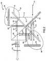
図2を参照すると、一実施形態で、例示的なカラー・マネジメント・システム200に、光セパレータ220、第1イメージ・アシミレータ230、第2イメージ・アシミレータ240、第1検光子235、第2検光子245、および光コンバイナ250が含まれる。この実施形態によれば、光セパレータ220が、光源から光ビーム210を受け取り、光ビーム210を2つまたはそれより多くの成分212、214、および216に分離し、それぞれに1つまたはそれより多くの成分が含まれる2つまたはそれより多くの光ビーム222および224を発する。たとえば、図2からわかるように、光セパレータ220は、第1成分および第2成分を含む光入力210を受け取るように位置決めされる。光セパレータ220は、前記第1成分を前記第2成分から分離し、前記第1成分212を含む第1光ビーム222ならびに前記第2成分214および第3成分216を含む第2光ビーム224を発するように構成される。光セパレータ220に、第1平面に配向された光を第2平面に配向された光から分離し、第1平面212に配向された光を含む第1光ビーム222および第2平面214に配向された光を含む第2光ビーム224を発するように構成された偏光ビームスプリッタを含めることができることに留意されたい。光セパレータ220に、二色性ミラー、二色性ビームスプリッタ、光学リターダに結合された二色性プリズム、プレート二色性ビームスプリッタ、または偏光ビームスプリッタを含めることができ、偏光ビームスプリッタに、さらに、ワイヤ・グリッド偏光子を含めることができることに留意されたい。光セパレータ220を、赤色光出力、緑色光出力、青色光出力、および/または緑色光と青色光を含むシアン光出力を作るように構成することができる。図2からわかるように、光セパレータ220は、変調された入力光ビーム210を受け取り、2つの出力光ビーム222および224を発するように構成された二色性プレート・ビームスプリッタである。一実施形態で、第1出力光ビーム222に、赤成分212が含まれ、第2出力光ビーム224に、青成分214および緑成分216が含まれる。 Referring to FIG. 2, in one embodiment, the exemplary
光セパレータ220を、赤、緑、青からなるか、白色光出力などの所望の出力を作るために再組合せすることができる他の組合せからなるものとすることができる別々のスペクトル・バンドに光の色を一時的に変調することによってカラー・イメージが生成される光を作るように構成することもできることに留意されたい。図2からわかるように、光セパレータ220は、変調された入力光ビーム210を受け取り、2つの出力光ビーム222および224を発するように構成された偏光プレート・ビームスプリッタである。第1出力光ビーム222に、偏光成分212が含まれる。第2出力光ビーム224に、第1光ビーム222の偏光成分212と実質的に直交する偏光成分214が含まれる。 The
一般に、偏光ビームスプリッタ220が、初期光ビーム210を、光の2つの発する直線偏光のビーム222および224に分離するように構成された装置であることに留意されたい。したがって、偏光ビームスプリッタ220に、光210を異なる色の成分212および214に分離するように構成されたコーティングを有する二色性ミラーを含めることができる。たとえば、通常のコーティングは、薄膜誘電体コーティングとすることができる。もう1つの実施形態で、偏光ビームスプリッタ220を、たとえば色または偏光に基づいて光を2つの異なる成分212および214に分離するように構成されたコーティングを有する誘電ビームスプリッタとすることができる。 Note that, in general,
本発明によれば、偏光ビームスプリッタ220は、第1平面に配向された偏光を第2平面に配向された偏光から分離するように構成される。例示的実施形態で、偏光ビームスプリッタ220を、第1平面212に配向された偏光を第1方向に発し、第2平面214に配向された偏光を第2方向に発するように構成することができ、第2方向は、第1方向と実質的に直交する。もう1つの例示的実施形態では、偏光ビームスプリッタ220を、図2に示されているように、第2平面214に配向された偏光を実質的に伝達させ、第1平面212に配向された偏光を実質的に反射するように構成することができる。 In accordance with the present invention, the
もう1つの実施形態で、偏光ビームスプリッタ220を、第2平面に配向された偏光を実質的に反射し、第1平面に配向された偏光を実質的に伝達するように構成することができる。この実施形態によれば、複数のフォールド・ミラー(fold mirror)を使用して、カラー・マネジメント・システムの素子の間でさまざまな光ビームを向けることができる。本明細書で使用されるフォールド・ミラーは、光を反射できるすべての反射面を指す。たとえば、フォールド・ミラーは、リヒテンシュタインのUnaxis社によって製造されるSiflexミラーなど、アルミ・ミラー(aluminized mirror)または機能強化されたシルバー・ミラーとすることができる。偏光ビームスプリッタ220に、アクティブ表面が互いに反対に面する偏光ビームスプリッタの対または両面にアクティブ表面を有する単一の偏光ビームスプリッタを含めることができる。 In another embodiment, the
図2をさらに参照すると、第1偏光ビームスプリッタ232および第1マイクロディスプレイ234を含む第1イメージ・アシミレータ230が、第1出力光ビーム222を受け取るように位置決めされる。第2偏光ビームスプリッタ242および第2マイクロディスプレイ244を含む第2イメージ・アシミレータ240が、第2出力光ビーム224を受け取るように位置決めされる。そのようなイメージ・アシミレータ230および240のそれぞれに、空間情報を含む光ビームを作るために、入ってくる光ビームの偏光を所定の形で修正し、光ビームに空間情報を重畳するように構成された反射型光空間変調器234および244を含めることができる。イメージ・アシミレータ230および240のそれぞれが、ディスプレイ・パネル234および244によって受け取られる入ってくる光ビームを実質的に伝達させ、ディスプレイ・パネルから修正光ビームを受け取り、検光子235および245によって直接受け取られる修正光ビーム236および246を発するように構成される。各イメージ・アシミレータ230および240に、プレート二色性ビームスプリッタ、光学リターダに結合されるかこれに結合されない二色性プリズム、さらにワイヤ・グリッド偏光子を含めることができる偏光ビームスプリッタを含めることができる。 With further reference to FIG. 2, a
この例示的実施形態によれば、第1イメージ・アシミレータ230は、第1出力光ビーム222を受け取り、その偏光配向を回転し、第1空間情報を与え、第1空間情報および雑音を含む第1修正光ビーム236を発する。第2イメージ・アシミレータ240は、第2出力光ビーム224を受け取り、その偏光配向を回転し、第2空間情報を与え、第2空間情報および雑音を含む第2修正光ビーム246を発する。この実施形態によれば、第1および第2の空間情報に、偏光が含まれる。 According to this exemplary embodiment, the
例示的実施形態で、イメージ・アシミレータ230および240に、二色性プリズムを含めることができる。代替実施形態で、イメージ・アシミレータ230および240を、実質的に同一の経路長のプリズムとすることができる。もう1つの例示的実施形態で、イメージ・アシミレータ230および240に、第2成分214および第3成分216を含む区別された光出力を作るために偏光フィルタを含めることができ、ここで、第2成分214の配向が、第3成分216の配向と直角になるように回転される。この代替実施形態によれば、イメージ・アシミレータ230および240に、さらに、偏光フィルタから区別された光出力を受け取るように位置決めされた第2偏光ビームスプリッタが含まれる。この第2偏光ビームスプリッタは、第2マイクロディスプレイによって受け取られる第2成分を実質的に伝達する前に、および第3マイクロディスプレイによって受け取られる第3成分を実質的に伝達する前に、第3成分216から第2成分214を分離するように構成される。 In the exemplary embodiment,
したがって、例示的実施形態では、イメージ・アシミレータ230および240から修正光出力を受け取り、1つまたはそれより多くの光ビームの偏光軸を回転することによって達成できる、単一平面に配向された偏光(すなわち、実質的に直線偏光の光)を作るために光をさらに修正するように位置決めされた検光子235および245によって、イメージのコントラストを高めることができる。もう1つの例示的実施形態では、検光子235および245を、フィルタ(すなわち色選択性遅延素子)の特性に応じて、光ビームから所定の波長の光を除去するように構成することができる。 Thus, in an exemplary embodiment, polarized light (in a single plane) that can be achieved by receiving the modified light output from the
本明細書で使用する用語「フィルタ」および「検光子」は、弁別する(すなわち、波長、配向、偏光、閃光、および/またはフィールド・レートなどの光の物理的特性に基づいて光束を阻止し、通過を許可し、かつ/または偏光特性を修正する)ように構成され、そうでなければ透明の基板の中または上のスペクトルに敏感な光学遅延薄膜などの光学的にアクティブな材料を組み込むか、偏光を作るために光を通すことができる細いギャップを残して互いに並列の配向の複数の非常に細いワイヤを配置するなどの当技術分野で既知の技法を使用して構成することができる、光フィルタおよび光学素子の組合せを指す。物理的特性に基づいて光を弁別するように構成されたフィルタの例に、米国カリフォルニア州Santa RosaのOCLI社およびリヒテンシュタインのUnaxis社が製造する二色性プレート、米国コロラド州BoulderのColorLink社が製造するColorSelectフィルタ、Polaroid社が製造する吸収性シート偏光子、および米国ユタ州MoxtekのMoxtek社が製造するProFlux偏光子および偏光ビームスプリッタが含まれる。 As used herein, the terms “filter” and “analyzer” discriminate (ie, block light flux based on physical properties of light, such as wavelength, orientation, polarization, flash, and / or field rate). Incorporate optically active materials such as spectrally sensitive optical retardation films that are otherwise configured to allow or pass and / or modify polarization properties) or otherwise in a transparent substrate Can be constructed using techniques known in the art, such as placing a plurality of very thin wires oriented parallel to each other, leaving a narrow gap through which light can pass to create polarized light, It refers to a combination of an optical filter and an optical element. Examples of filters configured to discriminate light based on physical properties include dichroic plates manufactured by Santa Rosa, California, USA and Unaxis, Liechtenstein, ColorLink, Inc., Boulder, Colorado, USA. ColorSelect filters manufactured, Absorbent sheet polarizers manufactured by Polaroid, and ProFlux polarizers and polarizing beam splitters manufactured by Moxtek of Moxtek, Utah, USA.
さらに図2を参照すると、例示的実施形態で、第1検光子235が、第1修正光出力236を第1イメージ・アシミレータ230から直接受け取るように位置決めされ、偏光に基づいて第1空間情報を雑音から分離するように構成される。この実施形態によれば、第1検光子235は、第1空間情報を実質的に透過させ、雑音の透過を防ぐか最小にするように構成され、雑音には、実質的に偏向されない光または所望の空間情報と同一の形で配向されていない偏光が含まれる。同様に、第2検光子245は、第2イメージ・アシミレータ240から直接第2修正光出力246を受け取るように位置決めされ、偏光に基づいて第2空間情報を雑音から実質的に分離するように構成される。また、この実施形態によれば、第2検光子245は、第2空間情報を実質的に透過し、雑音の透過を防ぐか最小にするように構成され、雑音には、やはり、実質的に偏向されない光または所望の空間情報と同一の形で配向されていない偏光が含まれる。第1検光子235および第2検光子245は、他の光学素子による修正の前に、第1および第2のイメージ・アシミレータ230および240から直接第1修正光出力236および第2修正光出力246を受け取るように位置決めされるので、第1および第2の検光子235および245は、イメージ・アシミレータ230および240によって与えられる雑音の実質的にすべてを、除去するか、最小にすることができる。 With further reference to FIG. 2, in an exemplary embodiment, the
検光子235および245が、光が光コンバイナ250などの別の光学素子を通過する前に、イメージ・アシミレータ230および240から直接光ビームを受け取るように位置決めされることに留意されたい。検光子235および245が、一般に、入ってくる光ビームに関して改善されたコントラストを有するフィルタ光出力を作るように構成されることにも留意されたい。イメージ・アシミレータ230および240から直接すなわち他の光学素子を通過するかこれによって修正される前に光ビームを受け取るように検光子235および245を位置決めすることによって、検光子235および245が、所望のイメージを含む光から偏光に基づいて雑音を区別できなくなる前に、実質的にすべての雑音を除去することができる。したがって、この実施形態は、従来技術のシステムに関して劇的に改善されたレベルのコントラストを有する。 Note that
本発明のもう1つの例示的実施形態によれば、各検光子235および245に、フィルタ(たとえば半波リターダまたは1/4波リターダなどの光学的リターダ素子)も含めることができる。フィルタに、光学リターダ素子が含まれる場合に、そのリターダ素子を、イメージ・アシミレータから発する光の偏光を選択的に修正し、その結果、発する光が実質的に直線偏光になり、さらに、各カラー・バンドの偏光軸が、実質的に各他のカラー・バンドの偏光軸と同一になるように構成することができる。上で述べたように、たとえばパネルの光学遅延を実質的に補償するために、イメージ・アシミレータ内の残留遅延と一致するために望まれる回転の範囲に応じて、特定の光学遅延、たとえば15ナノメートルと350ナノメートルの間の光学遅延を示すように、そのようなフィルタを選択できることに留意されたい。任意選択として、光学遅延素子の特性に応じて、検光子235および245によって、所定の波長または波長の帯域の光を光ビーム236および246から除去することができる。 According to another exemplary embodiment of the present invention, each
例示的実施形態で、カラー・マネジメント・システムに、検光子235および245から発するフィルタ光ビーム237および247を受け取るように位置決めされた光コンバイナ250も含まれる。光コンバイナ250は、実質的に光ビーム237および247を組み合わせて、単一のフィルタ光出力255を作るように構成される。たとえば、図2からわかるように、例示的実施形態で、本発明に、個々の光出力237および247から包括的な光出力255を形成する光コンバイナ250も含まれる。例示的実施形態で、光コンバイナ250に、光セパレータ220と同一の素子とすることができ、実質的にこれと同一の機能を提供する偏光ビームスプリッタが含まれる。光コンバイナ250に、二色性ビームスプリッタまたはxプリズムを含めることができる。光コンバイナ250がxプリズムである場合に、光コンバイナ250に、1つまたはそれより多くの二色性フィルタを含めることができ、偏光ビームスプリッタを含めることもできる。 In the exemplary embodiment, the color management system also includes an
xプリズムが、互いに実質的に直交する2つの平面を有する光学素子であることに留意されたい。例示的なxプリズムでは、第1平面が、第1波長を有する光を実質的に伝達させ、第2波長を有する光を実質的に反射するように構成された二色性フィルタである。そのような例示的xプリズムで、第1平面と実質的に直交する第2平面は、第1波長を有する光を実質的に反射し、第2波長を有する光を実質的に伝達させるように構成された二色性フィルタを有する。もう1つの例示的なxプリズムでは、第1平面が、第1波長を有する光を実質的に伝達させ、第2波長を有する光を実質的に反射するように構成された二色性フィルタである。この例示的なxプリズムでは、第1平面に実質的に直交する第2平面が、第1偏光に配向された光を実質的に反射し、第2偏光に配向された光を実質的に伝達させるように構成された偏光ビームスプリッタを有する。 Note that the x-prism is an optical element having two planes that are substantially orthogonal to each other. In the exemplary x-prism, the first plane is a dichroic filter configured to substantially transmit light having a first wavelength and substantially reflect light having a second wavelength. In such an exemplary x-prism, a second plane that is substantially orthogonal to the first plane substantially reflects light having the first wavelength and substantially transmits light having the second wavelength. It has a configured dichroic filter. In another exemplary x-prism, the first plane is a dichroic filter configured to substantially transmit light having a first wavelength and substantially reflect light having a second wavelength. is there. In this exemplary x-prism, a second plane substantially orthogonal to the first plane substantially reflects light oriented to the first polarization and substantially transmits light oriented to the second polarization. A polarizing beam splitter configured to be configured.
図2に示された実施形態など、第1出力光ビーム222が、第2出力光ビーム224と実質的に垂直の向きである例示的実施形態で、第1偏光ビームスプリッタ232および第2偏光ビームスプリッタ242に、偏光ビームスプリッタ232および242の表面から実質的に45°の角度で第1出力光ビーム222および第2出力光ビーム224の両方を受け取るように配向された同一の偏光ビームスプリッタを含めることができる。この実施形態によれば、偏光ビームスプリッタ232および242は、第1マイクロディスプレイ234によって受け取られる第1出力光ビーム222を実質的に伝達させ、第2マイクロディスプレイ244によって受け取られる第2出力光ビーム224を実質的に伝達させるように構成される。偏光ビームスプリッタ232および242は、実質的に45°の角度で第1および第2修正光ビーム236および246を受け取るようにも位置決めされる。しかし、修正光ビーム236および246の偏光は、光ビーム222および224の配向から回転されているので、偏光ビームスプリッタ232および242は、修正光ビーム236および246を実質的に反射するように構成される。したがって、この実施形態によれば、修正光ビーム236および246の両方を、直接光コンバイナ250に向けることができる。光ビームを向け直す他の素子を使用せずに、単一の偏光ビームスプリッタ232および242を使用し、修正光ビーム236および246を光コンバイナ250に直接向ける能力によって、他のカラー・マネジメント・システムに関してコスト、複雑さ、およびサイズが大幅に減る。最後に、このカラー・マネジメント・システムに、イメージを投射するために空間情報を含む出力光ビームを投射する投射レンズ270を含めることができる。 In an exemplary embodiment where the first
図4に示されるような例示的実施形態で、カラー・マネジメント・システム400に、第1イメージ・アシミレータ430および第2イメージ・アシミレータ440に加えて、第3イメージ・アシミレータ480を含めることができる。この実施形態によれば、緑の光空間変調器434を含む第1イメージ・アシミレータ430が、第1光ビーム422を受け取るように位置決めされる。赤のマイクロディスプレイ444を含む第2イメージ・アシミレータ440は、第2光ビーム424を受け取るように位置決めされる。青のパネル484を含む第3イメージ・アシミレータ480は、第3光ビーム426を受け取るように位置決めされる。各イメージ・アシミレータ430、440、および480は、入ってくる光ビームの偏光を所定の形で修正し、空間情報を含む光ビームを作るために光ビームに空間情報を重畳するように構成される。そのようなイメージ・アシミレータ430、440、および480のそれぞれは、ディスプレイ・パネル434、444、および484によって受け取られる入ってくる光ビームを実質的に伝達させ、ディスプレイ・パネルから修正光ビームを受け取り、検光子435、445、および485によって直接受け取られる修正光ビーム436、446、および486を発するように構成される。 In the exemplary embodiment as shown in FIG. 4, the
この例示的実施形態によれば、第1イメージ・アシミレータ430は、第1光ビーム422を受け取り、その偏光配向を回転し、第1空間情報を与え、第1空間情報および雑音を含む第1修正光ビーム436を発する。第2イメージ・アシミレータ440は、第2光ビーム424を受け取り、その偏光配向を回転し、第2空間情報を与え、第2空間情報および雑音を含む第2修正光ビーム446を発する。第3イメージ・アシミレータ480は、第3光ビーム484を受け取り、その偏光配向を回転し、第3空間情報を与え、第3空間情報および雑音を含む第3修正光ビーム486を発する。この実施形態によれば、第1、第2、および第3の空間情報に、偏光が含まれる。 According to this exemplary embodiment, the
したがって、この例示的実施形態で、イメージ・アシミレータ430、440、および480から修正光出力を受け取り、単一平面内の偏光配向を作る(すなわち実質的に直線偏光の光)ために光をさらに修正し、1つまたはそれより多くの光ビームの偏光軸を回転することによって達成できるように、位置決めされた検光子435、445、および485によって、イメージのコントラストを高めることができる。また、もう1つの例示的実施形態の説明に関して述べたように、検光子435、445、および485を、フィルタ(すなわち色選択性遅延素子)の特性に応じて、光ビームから所定の波長の光を除去するように構成することができる。 Thus, in this exemplary embodiment, the modified light output is received from
当業者が諒解するように、さまざまな構成を構築して、白色光を含む入力光ビームを複数の成分光ビームに効果的に分離することができ、これらの成分光ビームに空間情報を与えることができ、これらの成分光ビームから、複数の対応する検光子によって直接受け取られるイメージ・アシミレータからのそのような修正された成分光ビームを渡すことによって、雑音を効果的に分離し、除去することができる。そのような構成に、入力光を成分光ビームに分離し、関連するイメージ・アシミレータによって受け取ることができるようにこれらの成分光ビームを向ける偏光ビームスプリッタ、ミラー、および/または視野レンズの組合せを含めることができる。たとえば、図4に示されているように、ある例示的実施形態で、入力光ビーム410を、第1レンズ491によって受け取ることができ、この第1レンズ491は、二色性ビームスプリッタ492によって受け取られる光ビームを伝達させる。二色性ビームスプリッタは、第1成分422および第2成分424を伝達させるが、第3成分426を反射する。レンズ493は、反射された成分426を受け取り、ミラー494によって受け取られる成分426を伝達させる。ミラー494は、レンズ493から成分426を受け取り、レンズ495によって受け取られる成分426を反射するように位置決めされる。レンズ495は、ミラー494から成分426を受け取り、イメージ・アシミレータ480によって受け取られる成分426を伝達させる。図4をさらに参照すると、二色性ビームスプリッタ496は、二色性ビームスプリッタ492から成分422および424を受け取るように位置決めされ、イメージ・アシミレータ430によって受け取られる成分422を反射すると同時に、イメージ・アシミレータ440によって受け取られる成分424を伝達させるように構成される。最後に、イメージ・アシミレータ430および440から発する光は、当技術分野で既知のさまざまな機構、たとえば、1つまたはそれより多くのPhilipsプリズム、修正Philipsプリズム、プランビコン・プリズム、xプリズム、3チャネル・プリズム、リコンバイニング・プリズム、および類似物を使用して再組合せすることができる。たとえば、図4からわかるように、イメージ・アシミレータ430および440から発する光を、xプリズムを使用して再組合せすることができる。 As one skilled in the art will appreciate, various configurations can be constructed to effectively separate the input light beam, including white light, into multiple component light beams, giving spatial information to these component light beams. Effectively separating and removing noise from these component light beams by passing such modified component light beams from an image accumulator received directly by a plurality of corresponding analyzers. Can do. Such a configuration includes a combination of polarizing beam splitters, mirrors, and / or field lenses that separate the input light into component light beams and direct these component light beams so that they can be received by an associated image accumulator. be able to. For example, as shown in FIG. 4, in an exemplary embodiment, the
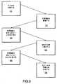
図3を参照すると、本発明の例示的実施形態によれば、投射システムのカラー・マネジメントを提供する方法に、空間情報および雑音を含む2つまたは3つ以上の入力光ビームを関連するイメージ・アシミレータから直接受け取るステップ(ステップ320)と、光ビームのそれぞれの空間情報から雑音を分離するステップ(ステップ330)と、空間情報を含むフィルタ光出力を発するステップ(ステップ340)とが含まれ、これによって、出力光ビームが、入力光ビームに関して改善されたコントラストを有する。 Referring to FIG. 3, according to an exemplary embodiment of the present invention, a method for providing color management of a projection system includes an image associated with two or more input light beams including spatial information and noise. Receiving directly from the accumulator (step 320), separating noise from the respective spatial information of the light beam (step 330), and emitting a filtered light output containing the spatial information (step 340), The output light beam has an improved contrast with respect to the input light beam.
したがって、関連するイメージ・アシミレータから直接光ビームを受け取るように位置決めされた密結合された検光子を使用することによって、カラー・マネジメント・システムが、イメージ・アシミレータのそれぞれによって入力ビームに与えられる雑音の実質的な部分を効果的に除去でき、従来技術に関して優れたコントラストを有する出力ビームを作ることができるようになる。さらに、本発明が、偏光依存素子および二色性素子の両方を使用して、入力光を複数のカラー・バンドに分割し、これらのカラー・バンドに、対応する複数のマイクロディスプレイによって空間情報を重畳することができ、修正カラー・バンドを再組合せして、高コントラストのフルカラー投射イメージを作ることができる。当業者は、本発明のカラー・マネジメント・システムを、本明細書で主に説明した2パネル・システムならびに3パネル・システムなどの複数パネル・システムで使用されるように適合できることを諒解するであろう。 Therefore, by using a tightly coupled analyzer positioned to receive the light beam directly from the associated image accumulator, the color management system can reduce the noise applied to the input beam by each of the image accumulators. A substantial part can be effectively removed, and an output beam having excellent contrast with respect to the prior art can be made. In addition, the present invention uses both polarization-dependent and dichroic elements to divide the input light into multiple color bands, and spatial information is provided to these color bands by corresponding microdisplays. They can be superimposed and the modified color bands can be recombined to create a high contrast full color projection image. Those skilled in the art will appreciate that the color management system of the present invention can be adapted for use in multiple panel systems such as the two panel systems described herein, as well as the three panel systems. Let's go.
したがって、本発明は、偏光依存素子および二色性素子の両方を使用して、入力光を複数のカラー・バンドに分割し(ステップ310)、対応する複数のマイクロディスプレイによってそれらのカラー・バンドに空間情報を重畳することができ(ステップ315)、修正カラー・バンドをフィルタリングして、空間情報から雑音を除去し(ステップ330)、これによってコントラストを改善し、その後、高コントラスト・イメージを再組合せして(ステップ350)、フルカラー投射イメージを作る。 Thus, the present invention uses both polarization dependent and dichroic elements to divide the input light into multiple color bands (step 310), and to those color bands by corresponding multiple microdisplays. Spatial information can be superimposed (step 315), and the modified color band is filtered to remove noise from the spatial information (step 330), thereby improving contrast and then recombining the high contrast image (Step 350) to create a full color projection image.
本発明を、さまざまな例示的実施形態に関して上で説明した。しかし、本発明の範囲から逸脱せずに、例示的実施形態に対してさまざまな変更および修正を行えることを、当業者は理解するであろう。たとえば、さまざまな素子を、たとえば他の光学的構成または配置を設けることによって、代替の形で実施することができる。これらの代替物は、特定の応用例に応じてまたはシステムの動作に関連する複数の要因を考慮して適当に選択することができる。さらに、上記および他の変更または修正は、請求項に示された本発明の範囲に含まれることが意図されている。 The present invention has been described above with reference to various exemplary embodiments. However, one of ordinary skill in the art appreciates that various changes and modifications can be made to the exemplary embodiments without departing from the scope of the invention. For example, the various elements can be implemented in alternative ways, for example by providing other optical configurations or arrangements. These alternatives can be appropriately selected depending on the particular application or considering several factors related to the operation of the system. Furthermore, these and other changes or modifications are intended to be included within the scope of the present invention as set forth in the claims.
Claims (43)
Translated fromJapanese前記第1検光子が、空間情報を含む第1光ビームを第1イメージ・アシミレータから受け取るように位置決めされ、前記第1検光子が、前記第1光ビームに関して改善されたコントラストを有する第1フィルタ光出力を作るように構成され、
前記第2検光子が、空間情報を含む第2光ビームを第2イメージ・アシミレータから受け取るように位置決めされ、前記第2検光子が、前記第2光ビームに関して改善されたコントラストを有する第2フィルタ光出力を作るように構成される
カラー・マネジメント・システム。A color management system including a first analyzer and a second analyzer,
The first analyzer is positioned to receive a first light beam containing spatial information from a first image accumulator, the first analyzer having a improved contrast with respect to the first light beam. Configured to make light output,
The second analyzer is positioned to receive a second light beam containing spatial information from a second image accumulator, and the second analyzer has a second filter having improved contrast with respect to the second light beam. A color management system configured to create light output.
前記第3光ビームを受け取るように位置決めされた補助イメージ・アシミレータであって、前記補助イメージ・アシミレータが、さらに、修正第3光ビームを発するように構成され、前記修正第3光ビームが、前記第3光ビームに重畳された空間情報を含む、補助イメージ・アシミレータと
をさらに含む、請求項31に記載のカラー・マネジメント・システム。A second optical separator positioned to receive optical input before the first optical separator, wherein the optical input comprises the first component, the second component, and a third component; A second optical separator configured to separate the third component from the first component and the second component and to emit a third light beam including the binary light input and the third component; When,
An auxiliary image accumulator positioned to receive the third light beam, the auxiliary image accumulator further configured to emit a modified third light beam, wherein the modified third light beam is 32. The color management system of claim 31, further comprising an auxiliary image accumulator that includes spatial information superimposed on the third light beam.
第2位置で第2イメージ・アシミレータから第2空間情報および第2雑音を含む第2光ビームを受け取るステップと、
前記第1位置で前記第1雑音から前記第1空間情報を分離するステップと、
前記第2位置で前記第2雑音から前記第2空間情報を分離するステップと、
前記第1位置から前記第1空間情報を含む第1フィルタ光出力を発するステップであって、前記第1フィルタ光出力が、前記第1光ビームに関して改善されたコントラストを有する、ステップと、
前記第2位置から前記第2空間情報を含む第2フィルタ光出力を発するステップであって、前記第2フィルタ光出力が、前記第2光ビームに関して改善されたコントラストを有する、ステップと
を含む、投写システムのカラー・マネジメントを容易にする方法。Receiving a first light beam including first spatial information and first noise from a first image accumulator at a first location;
Receiving a second light beam including second spatial information and second noise from a second image accumulator at a second location;
Separating the first spatial information from the first noise at the first position;
Separating the second spatial information from the second noise at the second position;
Emitting a first filtered light output including the first spatial information from the first position, wherein the first filtered light output has improved contrast with respect to the first light beam;
Emitting a second filtered light output including the second spatial information from the second position, wherein the second filtered light output has an improved contrast with respect to the second light beam. A method to facilitate color management of projection systems.
前記第1光ビームおよび前記第2光ビームを受け取るように位置決めされたイメージ・アシミレータであって、前記イメージ・アシミレータが、第1ディスプレイ・パネルによって受け取られる前記第1光ビームを実質的に伝達させ、前記第1ディスプレイ・パネルから修正第1光ビームを受け取り、前記修正第1光ビームを発するように構成され、前記イメージ・アシミレータが、さらに、第2ディスプレイ・パネルによって受け取られる前記第2光ビームを実質的に伝達させ、前記第2ディスプレイ・パネルから修正第2光ビームを受け取り、前記修正第2光ビームを発するように構成される、イメージ・アシミレータと、
前記修正第1光ビームを受け取るように位置決めされた第1検光子であって、前記第1検光子が、前記第1光出力に関して改善されたコントラストを有する第1フィルタ光出力を作るように構成される、第1検光子と、
前記修正第2光ビームを受け取るように位置決めされた第2検光子であって、前記第2検光子が、前記第2光出力に関して改善されたコントラストを有する第2フィルタ光出力を作るように構成される、第2検光子と
を含むカラー・マネジメント・システム。A first optical separator positioned to receive an optical input including a first component and a second component, wherein the optical separator separates the first component from the second component and includes the first component A first light separator configured to emit a first light beam and a second light beam comprising the second component;
An image accumulator positioned to receive the first light beam and the second light beam, wherein the image accumulator substantially transmits the first light beam received by a first display panel. Receiving the modified first light beam from the first display panel and emitting the modified first light beam, wherein the image accumulator is further received by the second display panel. An image accumulator configured to receive a modified second light beam from the second display panel and emit the modified second light beam;
A first analyzer positioned to receive the modified first light beam, the first analyzer configured to produce a first filtered light output having improved contrast with respect to the first light output. A first analyzer,
A second analyzer positioned to receive the modified second light beam, the second analyzer configured to produce a second filtered light output having an improved contrast with respect to the second light output. A color management system comprising a second analyzer.
第2位置で前記第1光ビームを受け取り、第1ディスプレイ・パネルによって受け取られる前記第1光ビームを前記第2位置から実質的に伝達させ、前記第2位置で前記第1ディスプレイ・パネルから修正第1光ビームを受け取り、前記第2位置から前記修正第1光ビームを発するステップと、
第3位置で前記第2光ビームを受け取り、1つまたはそれより多くのディスプレイ・パネルによって受け取られる前記第2光ビームを前記第3位置から実質的に伝達させ、前記第3位置で前記1つまたはそれより多くのディスプレイ・パネルから1つまたはそれより多くの修正第2光ビームを受け取り、前記1つまたはそれより多くの修正第2光ビームを前記第3位置から発するステップと、
第4位置で前記修正第1光ビームを受け取り、前記修正第1光ビームに関して改善されたコントラストを有する第1フィルタ光出力を前記第4位置から発するステップと、
第5位置で前記1つまたはそれより多くの修正第2光ビームを受け取り、前記1つまたはそれより多くの修正第2光ビームに関して改善されたコントラストを有する1つまたはそれより多くの第2フィルタ光出力を前記第5位置から発するステップと
を含む、投写システムのカラー・マネジメントを提供する方法。Receiving a light input including a first component and a second component at a first position, separating the first component from the second component at the first position, and first light including the first component from the first position; Emitting a beam and a second light beam comprising the second component;
Receiving the first light beam at a second position, substantially transmitting the first light beam received by the first display panel from the second position, and modifying from the first display panel at the second position; Receiving a first light beam and emitting the modified first light beam from the second position;
Receiving the second light beam at a third position and substantially transmitting the second light beam received by one or more display panels from the third position, wherein the one at the third position; Receiving one or more modified second light beams from or more display panels and emitting the one or more modified second light beams from the third position;
Receiving the modified first light beam at a fourth position and emitting a first filtered light output from the fourth position having improved contrast with respect to the modified first light beam;
One or more second filters that receive the one or more modified second light beams at a fifth position and have improved contrast with respect to the one or more modified second light beams Emitting light output from the fifth position, and providing color management of the projection system.
Applications Claiming Priority (4)
| Application Number | Priority Date | Filing Date | Title |
|---|---|---|---|
| US37887902P | 2002-05-08 | 2002-05-08 | |
| US10/213,505US6851812B2 (en) | 2001-08-06 | 2002-08-06 | Color management system |
| US10/310,383US6857747B2 (en) | 2001-08-06 | 2002-12-05 | Color management system |
| PCT/US2002/039682WO2003096703A1 (en) | 2002-05-08 | 2002-12-11 | Color management system |
Publications (1)
| Publication Number | Publication Date |
|---|---|
| JP2005524881Atrue JP2005524881A (en) | 2005-08-18 |
Family
ID=29424436
Family Applications (3)
| Application Number | Title | Priority Date | Filing Date |
|---|---|---|---|
| JP2004504527APendingJP2005524881A (en) | 2002-05-08 | 2002-12-11 | Color management system |
| JP2004504529APendingJP2005524883A (en) | 2002-05-08 | 2003-05-08 | Color management system with field lens |
| JP2004504528APendingJP2005524882A (en) | 2002-05-08 | 2003-05-08 | Color management system with transmissive panel and optical isolator |
Family Applications After (2)
| Application Number | Title | Priority Date | Filing Date |
|---|---|---|---|
| JP2004504529APendingJP2005524883A (en) | 2002-05-08 | 2003-05-08 | Color management system with field lens |
| JP2004504528APendingJP2005524882A (en) | 2002-05-08 | 2003-05-08 | Color management system with transmissive panel and optical isolator |
Country Status (8)
| Country | Link |
|---|---|
| US (1) | US6857747B2 (en) |
| EP (3) | EP1502445B1 (en) |
| JP (3) | JP2005524881A (en) |
| CN (3) | CN100345451C (en) |
| AU (3) | AU2002361644A1 (en) |
| DE (2) | DE60216327T2 (en) |
| TW (3) | TWI251090B (en) |
| WO (3) | WO2003096703A1 (en) |
Families Citing this family (50)
| Publication number | Priority date | Publication date | Assignee | Title |
|---|---|---|---|---|
| DE19847161A1 (en)* | 1998-10-14 | 2000-04-20 | Degussa | Fumed silica doped with aerosol |
| US6893130B2 (en)* | 2001-08-06 | 2005-05-17 | Advanced Digital Optics, Inc. | Color management system having a field lens |
| US7061561B2 (en) | 2002-01-07 | 2006-06-13 | Moxtek, Inc. | System for creating a patterned polarization compensator |
| US6909473B2 (en) | 2002-01-07 | 2005-06-21 | Eastman Kodak Company | Display apparatus and method |
| CN2563599Y (en)* | 2002-05-14 | 2003-07-30 | 邵剑心 | New silicon base liquid crystal color micro display device |
| US6805445B2 (en)* | 2002-06-05 | 2004-10-19 | Eastman Kodak Company | Projection display using a wire grid polarization beamsplitter with compensator |
| US6935746B2 (en)* | 2003-04-15 | 2005-08-30 | Infocus Corporation | Method and apparatus for reducing scattered light in a projection system |
| KR100546606B1 (en)* | 2003-05-14 | 2006-01-26 | 엘지전자 주식회사 | Reflective Illumination Optics |
| CN100476505C (en)* | 2003-07-18 | 2009-04-08 | 晶荧光学科技有限公司 | A three-dimensional/two-dimensional switchable color projection display device and method thereof |
| US7626661B2 (en)* | 2003-12-11 | 2009-12-01 | Jds Uniphase Corporation | Polarization controlling elements |
| US8164721B2 (en) | 2003-12-11 | 2012-04-24 | Tan Kim L | Grating trim retarders |
| KR20050069828A (en)* | 2003-12-31 | 2005-07-05 | 엘지전자 주식회사 | Projection device of high resolution |
| US7261418B2 (en)* | 2004-11-12 | 2007-08-28 | 3M Innovative Properties Company | Projection apparatus |
| US7630133B2 (en) | 2004-12-06 | 2009-12-08 | Moxtek, Inc. | Inorganic, dielectric, grid polarizer and non-zero order diffraction grating |
| US7800823B2 (en) | 2004-12-06 | 2010-09-21 | Moxtek, Inc. | Polarization device to polarize and further control light |
| US7570424B2 (en) | 2004-12-06 | 2009-08-04 | Moxtek, Inc. | Multilayer wire-grid polarizer |
| US7961393B2 (en) | 2004-12-06 | 2011-06-14 | Moxtek, Inc. | Selectively absorptive wire-grid polarizer |
| US8237876B2 (en)* | 2005-05-25 | 2012-08-07 | Kim Leong Tan | Tilted C-plate retarder compensator and display systems incorporating the same |
| EP1764644B1 (en)* | 2005-09-09 | 2017-08-30 | Viavi Solutions Inc. | Optimally oriented trim retarders |
| US7445341B2 (en)* | 2005-09-21 | 2008-11-04 | 3M Innovative Properties Company | Four panel liquid crystal display system |
| JP4661510B2 (en)* | 2005-10-03 | 2011-03-30 | 日本ビクター株式会社 | Projection display device and three-plate liquid crystal projector |
| TW200728830A (en)* | 2005-10-18 | 2007-08-01 | Jds Uniphase Corp | Electronically compensated LCD assembly |
| US7614753B2 (en)* | 2005-10-31 | 2009-11-10 | Hewlett-Packard Development Company, L.P. | Determining an adjustment |
| US7896489B2 (en)* | 2005-11-02 | 2011-03-01 | Fujifilm Corporation | Image recording apparatus |
| US7641350B2 (en)* | 2005-11-28 | 2010-01-05 | Jds Uniphase Corporation | Front surface mirror for providing white color uniformity for polarized systems with a large range of incidence angles |
| US20070195257A1 (en)* | 2006-02-21 | 2007-08-23 | Jds Uniphase Corporation | LC imager panel assembly |
| US8755113B2 (en) | 2006-08-31 | 2014-06-17 | Moxtek, Inc. | Durable, inorganic, absorptive, ultra-violet, grid polarizer |
| DK1980902T3 (en)* | 2007-04-10 | 2015-07-27 | Jds Uniphase Corp | Twisted nematic XLCD CONTRAST COMPENSATION WITH rocked PLADEFORSINKERE |
| US7789515B2 (en) | 2007-05-17 | 2010-09-07 | Moxtek, Inc. | Projection device with a folded optical path and wire-grid polarizer |
| CN101435983A (en)* | 2007-11-14 | 2009-05-20 | 鸿富锦精密工业(深圳)有限公司 | Projection display |
| CN101952766B (en)* | 2007-12-28 | 2012-07-11 | 3M创新有限公司 | Light combiner |
| KR20100099747A (en)* | 2007-12-28 | 2010-09-13 | 쓰리엠 이노베이티브 프로퍼티즈 컴파니 | Light combiner |
| EP2286296A4 (en)* | 2008-05-15 | 2011-09-07 | 3M Innovative Properties Co | Optical element and color combiner |
| JP5449331B2 (en)* | 2008-05-15 | 2014-03-19 | スリーエム イノベイティブ プロパティズ カンパニー | Optical element and color synthesizer |
| US9203513B2 (en)* | 2008-05-15 | 2015-12-01 | Teledyne Scientific & Imaging, Llc | SNR enhancement in modulating retroreflector optical communication links |
| JP5388534B2 (en)* | 2008-10-09 | 2014-01-15 | キヤノン株式会社 | Image processing apparatus and method, head-mounted display, program, and recording medium |
| JP2012509507A (en)* | 2008-11-19 | 2012-04-19 | スリーエム イノベイティブ プロパティズ カンパニー | High durability color synthesizer |
| US8654444B2 (en) | 2008-11-19 | 2014-02-18 | 3M Innovative Properties Company | Polarization converting color combiner |
| KR20110086163A (en)* | 2008-11-19 | 2011-07-27 | 쓰리엠 이노베이티브 프로퍼티즈 컴파니 | Polarization conversion color combiner |
| US8248696B2 (en) | 2009-06-25 | 2012-08-21 | Moxtek, Inc. | Nano fractal diffuser |
| JP5751098B2 (en)* | 2010-09-08 | 2015-07-22 | 旭硝子株式会社 | Projection display |
| US8913321B2 (en) | 2010-09-21 | 2014-12-16 | Moxtek, Inc. | Fine pitch grid polarizer |
| US8611007B2 (en) | 2010-09-21 | 2013-12-17 | Moxtek, Inc. | Fine pitch wire grid polarizer |
| US8913320B2 (en) | 2011-05-17 | 2014-12-16 | Moxtek, Inc. | Wire grid polarizer with bordered sections |
| US8873144B2 (en) | 2011-05-17 | 2014-10-28 | Moxtek, Inc. | Wire grid polarizer with multiple functionality sections |
| US8922890B2 (en) | 2012-03-21 | 2014-12-30 | Moxtek, Inc. | Polarizer edge rib modification |
| WO2013162895A1 (en)* | 2012-04-25 | 2013-10-31 | 3M Innovative Properties Company | Two imager projection device |
| US10477194B2 (en) | 2012-04-25 | 2019-11-12 | 3M Innovative Properties Company | Two imager projection device |
| US9354374B2 (en) | 2013-10-24 | 2016-05-31 | Moxtek, Inc. | Polarizer with wire pair over rib |
| CN112630985B (en)* | 2020-12-28 | 2021-09-14 | 福建福特科光电股份有限公司 | Color separation device and color separation method of black light lens |
Family Cites Families (47)
| Publication number | Priority date | Publication date | Assignee | Title |
|---|---|---|---|---|
| US3637308A (en) | 1970-06-11 | 1972-01-25 | Rca Corp | Color correction of prismatic off-axis optical system |
| US3868168A (en) | 1973-01-16 | 1975-02-25 | American Optical Corp | Combination of birefringent elements for polarizing interferential systems |
| US3982819A (en) | 1975-05-22 | 1976-09-28 | The United States Of America As Represented By The Secretary Of The Navy | Fluid gap glan-laser prism |
| US4864390A (en) | 1986-08-22 | 1989-09-05 | North American Philips Corporation | Display system with equal path lengths |
| US5235443A (en) | 1989-07-10 | 1993-08-10 | Hoffmann-La Roche Inc. | Polarizer device |
| US5231431A (en) | 1989-11-29 | 1993-07-27 | Canon Kabushiki Kaisha | Projection type display apparatus |
| US5315330A (en) | 1989-12-21 | 1994-05-24 | Sharp Kabushiki Kaisha | Projection type display apparatus |
| JPH04180010A (en) | 1990-11-15 | 1992-06-26 | Fuji Photo Optical Co Ltd | Splitting prism for luminous flux |
| US5268775A (en) | 1991-02-19 | 1993-12-07 | Hughes-Jvc Technology Corporation | Contrast enhancement and ghost elimination, for reflective light valve system |
| US5552922A (en) | 1993-04-12 | 1996-09-03 | Corning Incorporated | Optical system for projection display |
| US5374968A (en) | 1993-11-08 | 1994-12-20 | Greyhawk Systems, Inc. | Optics for a single-lens video projector with color-specific polarization channels |
| EP1233627A3 (en) | 1993-12-17 | 2007-04-04 | Matsushita Electric Industrial Co., Ltd. | Liquid crystal projection device and liquid crystal display device |
| KR100236107B1 (en) | 1994-03-09 | 1999-12-15 | 전주범 | PROJECTION DISPLAY SYSTEM |
| WO1995030922A1 (en) | 1994-05-06 | 1995-11-16 | Philips Electronics N.V. | Beam-combining device and colour image projection apparatus provided with such a device |
| JP3778364B2 (en) | 1994-06-17 | 2006-05-24 | タレス | Filtering device and its application to liquid crystal projector |
| EP0722253A3 (en) | 1995-01-10 | 1996-10-30 | Ibm | Arrangements for projection displays employing reflective light valves |
| US6183091B1 (en)* | 1995-04-07 | 2001-02-06 | Colorlink, Inc. | Color imaging systems and methods |
| JP3113169B2 (en) | 1995-04-24 | 2000-11-27 | 富士写真光機株式会社 | Astigmatism correction element |
| US5621486A (en) | 1995-06-22 | 1997-04-15 | International Business Machines Corporation | Efficient optical system for a high resolution projection display employing reflection light valves |
| JP3690006B2 (en) | 1996-10-31 | 2005-08-31 | ソニー株式会社 | Video projection device |
| JP3414164B2 (en) | 1996-10-31 | 2003-06-09 | ミノルタ株式会社 | LCD projector |
| EP0841821A3 (en) | 1996-11-06 | 2000-01-12 | Canon Kabushiki Kaisha | Projection apparatus |
| JP3444521B2 (en)* | 1997-06-20 | 2003-09-08 | シャープ株式会社 | Projection type image display device |
| JPH1164852A (en) | 1997-08-21 | 1999-03-05 | Hitachi Ltd | Projection type liquid crystal display |
| US6046858A (en) | 1997-10-16 | 2000-04-04 | Aurora Systems, Inc. | Light separation and recombination system for an off-axis projector |
| US6273568B1 (en) | 1998-02-05 | 2001-08-14 | Canon Kabushiki Kaisha | Projection apparatus |
| US6176586B1 (en) | 1998-03-24 | 2001-01-23 | Minolta Co., Ltd. | Projection display apparatus |
| US6231190B1 (en) | 1998-06-22 | 2001-05-15 | Texas Instruments Incorporated | Color correction filter for displays |
| US6513934B1 (en) | 1999-02-17 | 2003-02-04 | Canon Kabushiki Kaisha | Projection apparatus and observation apparatus |
| JP2000347177A (en) | 1999-03-29 | 2000-12-15 | Minolta Co Ltd | Display optical device and projector display device using the same |
| JP3370010B2 (en) | 1999-03-31 | 2003-01-27 | 三洋電機株式会社 | LCD projector |
| WO2000063738A1 (en) | 1999-04-21 | 2000-10-26 | U.S. Precision Lens Incorporated | Optical systems for reflective lcd's |
| US6234634B1 (en) | 1999-07-28 | 2001-05-22 | Moxtek | Image projection system with a polarizing beam splitter |
| US6309071B1 (en)* | 1999-08-04 | 2001-10-30 | Sharp Laboratories Of America, Inc. | Liquid crystal projection display system |
| IL132928A0 (en) | 1999-11-14 | 2001-03-19 | Unic View Ltd | Thermally stable birefringent prism assembly |
| US6375330B1 (en) | 1999-12-30 | 2002-04-23 | Gain Micro-Optics, Inc. | Reflective liquid-crystal-on-silicon projection engine architecture |
| EP1143744B1 (en)* | 2000-03-17 | 2008-09-24 | Hitachi, Ltd. | Image display device |
| US6661475B1 (en) | 2000-03-23 | 2003-12-09 | Infocus Corporation | Color video projection system employing reflective liquid crystal display device |
| JP3768381B2 (en)* | 2000-05-11 | 2006-04-19 | 株式会社日立製作所 | LCD projector |
| JP2002049094A (en) | 2000-08-04 | 2002-02-15 | Minolta Co Ltd | Prism system and projection type video display device |
| KR100370658B1 (en)* | 2000-12-22 | 2003-02-05 | 삼성전기주식회사 | Device for color separation and combination |
| TW483532U (en)* | 2001-02-06 | 2002-04-11 | Delta Electronics Inc | Improvement on color management system of liquid-crystal-display projector |
| JP2002229125A (en) | 2001-02-06 | 2002-08-14 | Canon Inc | Projection type image display device and image display system |
| US6585378B2 (en) | 2001-03-20 | 2003-07-01 | Eastman Kodak Company | Digital cinema projector |
| US6457831B1 (en) | 2001-04-17 | 2002-10-01 | Prokia Technology Co., Ltd. | Projection display using reflective light modulators |
| US6545804B2 (en)* | 2001-06-13 | 2003-04-08 | Prokia Technology Co., Ltd. | Projection display with two reflective light valves |
| US6384972B1 (en)* | 2001-06-13 | 2002-05-07 | Prokia Technology Co., Ltd. | Projection display with three polarization beam splitter prisms |
- 2002
- 2002-12-05USUS10/310,383patent/US6857747B2/ennot_activeExpired - Fee Related
- 2002-12-11DEDE60216327Tpatent/DE60216327T2/ennot_activeExpired - Lifetime
- 2002-12-11CNCNB028289099Apatent/CN100345451C/ennot_activeExpired - Fee Related
- 2002-12-11WOPCT/US2002/039682patent/WO2003096703A1/enactiveIP Right Grant
- 2002-12-11AUAU2002361644Apatent/AU2002361644A1/ennot_activeAbandoned
- 2002-12-11EPEP02797283Apatent/EP1502445B1/ennot_activeExpired - Lifetime
- 2002-12-11JPJP2004504527Apatent/JP2005524881A/enactivePending
- 2002-12-13TWTW091136211Apatent/TWI251090B/ennot_activeIP Right Cessation
- 2003
- 2003-05-08JPJP2004504529Apatent/JP2005524883A/enactivePending
- 2003-05-08DEDE60315446Tpatent/DE60315446T2/ennot_activeExpired - Fee Related
- 2003-05-08TWTW092112557Apatent/TWI228001B/enactive
- 2003-05-08WOPCT/US2003/014888patent/WO2003096705A1/enactiveIP Right Grant
- 2003-05-08AUAU2003239420Apatent/AU2003239420A1/ennot_activeAbandoned
- 2003-05-08CNCNA038104385Apatent/CN1653825A/enactivePending
- 2003-05-08TWTW092112555Apatent/TW586048B/ennot_activeIP Right Cessation
- 2003-05-08CNCNA038103958Apatent/CN1653824A/enactivePending
- 2003-05-08EPEP03733998Apatent/EP1502447B1/ennot_activeExpired - Lifetime
- 2003-05-08AUAU2003239422Apatent/AU2003239422A1/ennot_activeAbandoned
- 2003-05-08EPEP03733997Apatent/EP1502446B1/ennot_activeExpired - Lifetime
- 2003-05-08WOPCT/US2003/014887patent/WO2003096704A1/enactiveIP Right Grant
- 2003-05-08JPJP2004504528Apatent/JP2005524882A/enactivePending
Also Published As
| Publication number | Publication date |
|---|---|
| WO2003096703A1 (en) | 2003-11-20 |
| CN1625903A (en) | 2005-06-08 |
| CN100345451C (en) | 2007-10-24 |
| TWI251090B (en) | 2006-03-11 |
| TWI228001B (en) | 2005-02-11 |
| DE60216327D1 (en) | 2007-01-04 |
| JP2005524882A (en) | 2005-08-18 |
| TW586048B (en) | 2004-05-01 |
| EP1502446B1 (en) | 2007-10-03 |
| TW200408284A (en) | 2004-05-16 |
| US6857747B2 (en) | 2005-02-22 |
| DE60216327T2 (en) | 2007-06-14 |
| AU2003239422A1 (en) | 2003-11-11 |
| EP1502446A1 (en) | 2005-02-02 |
| DE60315446D1 (en) | 2007-09-20 |
| CN1653824A (en) | 2005-08-10 |
| US20030081179A1 (en) | 2003-05-01 |
| DE60315446T2 (en) | 2008-05-08 |
| TW200306436A (en) | 2003-11-16 |
| JP2005524883A (en) | 2005-08-18 |
| CN1653825A (en) | 2005-08-10 |
| EP1502445B1 (en) | 2006-11-22 |
| WO2003096704A1 (en) | 2003-11-20 |
| TW200401157A (en) | 2004-01-16 |
| EP1502447B1 (en) | 2007-08-08 |
| EP1502445A1 (en) | 2005-02-02 |
| AU2002361644A1 (en) | 2003-11-11 |
| AU2003239420A1 (en) | 2003-11-11 |
| EP1502447A1 (en) | 2005-02-02 |
| WO2003096705A1 (en) | 2003-11-20 |
Similar Documents
| Publication | Publication Date | Title |
|---|---|---|
| JP2005524881A (en) | Color management system | |
| US7108374B2 (en) | Image display device having a field lens | |
| US7104650B2 (en) | Image display device having a transmissive panel and an optical isolator | |
| US7002752B2 (en) | Three-panel color management systems and methods | |
| US6851812B2 (en) | Color management system | |
| US5365287A (en) | Three color channel, two-elevation optics for a single lens video projector | |
| JP4380180B2 (en) | Image display device | |
| JP2005518562A (en) | System for projecting an image using a narrowband light source | |
| US6945654B2 (en) | Color management system having a prism to compensate for optical aberrations and to enhance contrast | |
| US7347561B2 (en) | Image display device | |
| WO2004046787A1 (en) | Three-panel color management systems and methods | |
| KR20050010785A (en) | Color management system |
Legal Events
| Date | Code | Title | Description |
|---|---|---|---|
| A521 | Request for written amendment filed | Free format text:JAPANESE INTERMEDIATE CODE: A821 Effective date:20050930 | |
| A711 | Notification of change in applicant | Free format text:JAPANESE INTERMEDIATE CODE: A711 Effective date:20050930 | |
| A521 | Request for written amendment filed | Free format text:JAPANESE INTERMEDIATE CODE: A821 Effective date:20050930 | |
| A621 | Written request for application examination | Free format text:JAPANESE INTERMEDIATE CODE: A621 Effective date:20051115 | |
| A131 | Notification of reasons for refusal | Free format text:JAPANESE INTERMEDIATE CODE: A131 Effective date:20081216 | |
| A02 | Decision of refusal | Free format text:JAPANESE INTERMEDIATE CODE: A02 Effective date:20090602 |