JP2005524683A - Method and apparatus for decontaminating fluids - Google Patents
Method and apparatus for decontaminating fluidsDownload PDFInfo
- Publication number
- JP2005524683A JP2005524683AJP2003583492AJP2003583492AJP2005524683AJP 2005524683 AJP2005524683 AJP 2005524683AJP 2003583492 AJP2003583492 AJP 2003583492AJP 2003583492 AJP2003583492 AJP 2003583492AJP 2005524683 AJP2005524683 AJP 2005524683A
- Authority
- JP
- Japan
- Prior art keywords
- fluid
- ozone
- chamber
- ultrasonic energy
- treating
- Prior art date
- Legal status (The legal status is an assumption and is not a legal conclusion. Google has not performed a legal analysis and makes no representation as to the accuracy of the status listed.)
- Pending
Links
- 239000012530fluidSubstances0.000titleclaimsabstractdescription655
- 238000000034methodMethods0.000titleclaimsabstractdescription323
- CBENFWSGALASAD-UHFFFAOYSA-NOzoneChemical compound[O-][O+]=OCBENFWSGALASAD-UHFFFAOYSA-N0.000claimsabstractdescription466
- 102000004169proteins and genesHuman genes0.000claimsabstractdescription151
- 108090000623proteins and genesProteins0.000claimsabstractdescription151
- 239000013060biological fluidSubstances0.000claimsabstractdescription39
- 239000007788liquidSubstances0.000claimsdescription139
- 238000005202decontaminationMethods0.000claimsdescription137
- 238000012545processingMethods0.000claimsdescription128
- 230000003588decontaminative effectEffects0.000claimsdescription123
- 238000002604ultrasonographyMethods0.000claimsdescription81
- 238000002156mixingMethods0.000claimsdescription53
- 239000000758substrateSubstances0.000claimsdescription38
- 230000001678irradiating effectEffects0.000claimsdescription26
- 239000010409thin filmSubstances0.000claimsdescription20
- 230000005251gamma rayEffects0.000claimsdescription15
- 238000005192partitionMethods0.000claimsdescription15
- 238000011282treatmentMethods0.000abstractdescription69
- 230000005855radiationEffects0.000abstractdescription16
- 210000002381plasmaAnatomy0.000description263
- 235000018102proteinsNutrition0.000description140
- 239000007789gasSubstances0.000description103
- 239000001301oxygenSubstances0.000description102
- 229910052760oxygenInorganic materials0.000description102
- 230000008569processEffects0.000description95
- QVGXLLKOCUKJST-UHFFFAOYSA-Natomic oxygenChemical compound[O]QVGXLLKOCUKJST-UHFFFAOYSA-N0.000description91
- 230000006378damageEffects0.000description88
- 238000007872degassingMethods0.000description77
- 241000700605VirusesSpecies0.000description68
- XLYOFNOQVPJJNP-UHFFFAOYSA-NwaterChemical compoundOXLYOFNOQVPJJNP-UHFFFAOYSA-N0.000description64
- 239000000463materialSubstances0.000description62
- 238000013459approachMethods0.000description60
- 210000004369bloodAnatomy0.000description53
- 239000008280bloodSubstances0.000description53
- 238000012360testing methodMethods0.000description47
- 239000000047productSubstances0.000description40
- 210000004027cellAnatomy0.000description39
- 230000008901benefitEffects0.000description35
- 230000000694effectsEffects0.000description34
- 244000052769pathogenSpecies0.000description34
- 210000001772blood plateletAnatomy0.000description32
- 239000010836blood and blood productSubstances0.000description29
- 238000010438heat treatmentMethods0.000description29
- 210000003743erythrocyteAnatomy0.000description27
- 239000010410layerSubstances0.000description27
- 229940125691blood productDrugs0.000description26
- 239000012678infectious agentSubstances0.000description26
- 150000003254radicalsChemical class0.000description26
- 239000007921spraySubstances0.000description26
- 239000000356contaminantSubstances0.000description25
- 238000006243chemical reactionMethods0.000description22
- 230000009467reductionEffects0.000description22
- 238000000527sonicationMethods0.000description22
- 239000000126substanceSubstances0.000description21
- 238000005516engineering processMethods0.000description20
- 230000002779inactivationEffects0.000description20
- 239000012528membraneSubstances0.000description20
- 230000002572peristaltic effectEffects0.000description20
- 238000011109contaminationMethods0.000description19
- 230000001717pathogenic effectEffects0.000description18
- 230000015572biosynthetic processEffects0.000description16
- 239000000243solutionSubstances0.000description16
- 102000004506Blood ProteinsHuman genes0.000description15
- 108010017384Blood ProteinsProteins0.000description15
- 230000005684electric fieldEffects0.000description15
- 230000000670limiting effectEffects0.000description15
- 239000004033plasticSubstances0.000description15
- 229920003023plasticPolymers0.000description15
- IJGRMHOSHXDMSA-UHFFFAOYSA-NAtomic nitrogenChemical compoundN#NIJGRMHOSHXDMSA-UHFFFAOYSA-N0.000description14
- 229920006362Teflon®Polymers0.000description14
- 239000000306componentSubstances0.000description14
- CURLTUGMZLYLDI-UHFFFAOYSA-NCarbon dioxideChemical compoundO=C=OCURLTUGMZLYLDI-UHFFFAOYSA-N0.000description13
- 108020004414DNAProteins0.000description13
- 239000003570airSubstances0.000description13
- 238000001816coolingMethods0.000description13
- 230000005484gravityEffects0.000description13
- 208000015181infectious diseaseDiseases0.000description13
- 239000004809TeflonSubstances0.000description12
- 238000009792diffusion processMethods0.000description12
- 230000033001locomotionEffects0.000description12
- -1oxygen radicalChemical class0.000description12
- 230000002829reductive effectEffects0.000description12
- 238000012546transferMethods0.000description12
- 241000125945ProtoparvovirusSpecies0.000description11
- 239000006260foamSubstances0.000description11
- 238000005259measurementMethods0.000description11
- 229910052751metalInorganic materials0.000description11
- 239000002184metalSubstances0.000description11
- 230000036961partial effectEffects0.000description11
- 238000003860storageMethods0.000description11
- 241000283690Bos taurusSpecies0.000description10
- 102000008946FibrinogenHuman genes0.000description10
- 108010049003FibrinogenProteins0.000description10
- 241000725303Human immunodeficiency virusSpecies0.000description10
- 239000003795chemical substances by applicationSubstances0.000description10
- 235000013305foodNutrition0.000description10
- VYPSYNLAJGMNEJ-UHFFFAOYSA-NSilicium dioxideChemical compoundO=[Si]=OVYPSYNLAJGMNEJ-UHFFFAOYSA-N0.000description9
- 230000008878couplingEffects0.000description9
- 238000010168coupling processMethods0.000description9
- 238000005859coupling reactionMethods0.000description9
- 238000013461designMethods0.000description9
- 229940012952fibrinogenDrugs0.000description9
- 230000001965increasing effectEffects0.000description9
- 238000009434installationMethods0.000description9
- 239000012460protein solutionSubstances0.000description9
- 238000010791quenchingMethods0.000description9
- 241000894006BacteriaSpecies0.000description8
- 230000009471actionEffects0.000description8
- 238000010586diagramMethods0.000description8
- 238000002474experimental methodMethods0.000description8
- 230000006870functionEffects0.000description8
- 238000006385ozonation reactionMethods0.000description8
- 244000045947parasiteSpecies0.000description8
- 230000000171quenching effectEffects0.000description8
- 241000894007speciesSpecies0.000description8
- 241000233866FungiSpecies0.000description7
- 239000012503blood componentSubstances0.000description7
- 230000008859changeEffects0.000description7
- 230000001276controlling effectEffects0.000description7
- 238000011161developmentMethods0.000description7
- 239000003814drugSubstances0.000description7
- 229910052757nitrogenInorganic materials0.000description7
- 108010054218Factor VIIIProteins0.000description6
- 102000001690Factor VIIIHuman genes0.000description6
- 238000002617apheresisMethods0.000description6
- 239000007864aqueous solutionSubstances0.000description6
- 230000005540biological transmissionEffects0.000description6
- 229960000074biopharmaceuticalDrugs0.000description6
- 229910002092carbon dioxideInorganic materials0.000description6
- 239000001569carbon dioxideSubstances0.000description6
- 230000007423decreaseEffects0.000description6
- 238000001514detection methodMethods0.000description6
- 239000003599detergentSubstances0.000description6
- 229940079593drugDrugs0.000description6
- 238000011049fillingMethods0.000description6
- 238000004519manufacturing processMethods0.000description6
- 230000007246mechanismEffects0.000description6
- 230000003287optical effectEffects0.000description6
- 238000005457optimizationMethods0.000description6
- 238000000926separation methodMethods0.000description6
- 239000002904solventSubstances0.000description6
- 241000282412HomoSpecies0.000description5
- 102000029797PrionHuman genes0.000description5
- 108091000054PrionProteins0.000description5
- 230000015556catabolic processEffects0.000description5
- 210000000170cell membraneAnatomy0.000description5
- 230000001413cellular effectEffects0.000description5
- 230000035602clottingEffects0.000description5
- 238000007906compressionMethods0.000description5
- 230000006835compressionEffects0.000description5
- 230000001066destructive effectEffects0.000description5
- 201000010099diseaseDiseases0.000description5
- 208000037265diseases, disorders, signs and symptomsDiseases0.000description5
- 229960000301factor viiiDrugs0.000description5
- 238000007710freezingMethods0.000description5
- 230000008014freezingEffects0.000description5
- 239000011521glassSubstances0.000description5
- 230000012010growthEffects0.000description5
- 230000001976improved effectEffects0.000description5
- 238000000338in vitroMethods0.000description5
- 210000000265leukocyteAnatomy0.000description5
- 201000002364leukopeniaDiseases0.000description5
- 231100001022leukopeniaToxicity0.000description5
- 239000010453quartzSubstances0.000description5
- 239000007787solidSubstances0.000description5
- 229910001220stainless steelInorganic materials0.000description5
- 239000010935stainless steelSubstances0.000description5
- 230000009286beneficial effectEffects0.000description4
- 150000001875compoundsChemical class0.000description4
- 238000006731degradation reactionMethods0.000description4
- 235000013601eggsNutrition0.000description4
- 238000005868electrolysis reactionMethods0.000description4
- 239000005350fused silica glassSubstances0.000description4
- 230000002458infectious effectEffects0.000description4
- 239000011159matrix materialSubstances0.000description4
- 239000002609mediumSubstances0.000description4
- 239000000203mixtureSubstances0.000description4
- 238000012544monitoring processMethods0.000description4
- 230000009257reactivityEffects0.000description4
- 238000005057refrigerationMethods0.000description4
- 230000033764rhythmic processEffects0.000description4
- 230000001954sterilising effectEffects0.000description4
- 238000004659sterilization and disinfectionMethods0.000description4
- 230000002195synergetic effectEffects0.000description4
- 238000009849vacuum degassingMethods0.000description4
- 238000010792warmingMethods0.000description4
- 102000015081Blood Coagulation FactorsHuman genes0.000description3
- 108010039209Blood Coagulation FactorsProteins0.000description3
- 206010053567CoagulopathiesDiseases0.000description3
- UFHFLCQGNIYNRP-UHFFFAOYSA-NHydrogenChemical compound[H][H]UFHFLCQGNIYNRP-UHFFFAOYSA-N0.000description3
- 238000010521absorption reactionMethods0.000description3
- 230000002238attenuated effectEffects0.000description3
- 235000013405beerNutrition0.000description3
- 230000004071biological effectEffects0.000description3
- 239000003114blood coagulation factorSubstances0.000description3
- 238000004140cleaningMethods0.000description3
- 239000012141concentrateSubstances0.000description3
- 239000000498cooling waterSubstances0.000description3
- 230000000254damaging effectEffects0.000description3
- 239000003344environmental pollutantSubstances0.000description3
- 239000001257hydrogenSubstances0.000description3
- 229910052739hydrogenInorganic materials0.000description3
- 238000005286illuminationMethods0.000description3
- 238000007654immersionMethods0.000description3
- 230000006872improvementEffects0.000description3
- 230000003993interactionEffects0.000description3
- 230000002147killing effectEffects0.000description3
- 230000031700light absorptionEffects0.000description3
- 238000012423maintenanceMethods0.000description3
- 231100000719pollutantToxicity0.000description3
- 229920000642polymerPolymers0.000description3
- 238000011176poolingMethods0.000description3
- 238000005086pumpingMethods0.000description3
- 238000011084recoveryMethods0.000description3
- 230000002441reversible effectEffects0.000description3
- 210000002966serumAnatomy0.000description3
- 238000005393sonoluminescenceMethods0.000description3
- 238000003756stirringMethods0.000description3
- 231100000331toxicToxicity0.000description3
- 230000002588toxic effectEffects0.000description3
- 239000012780transparent materialSubstances0.000description3
- 238000009281ultraviolet germicidal irradiationMethods0.000description3
- 230000008016vaporizationEffects0.000description3
- 230000003612virological effectEffects0.000description3
- 208000030507AIDSDiseases0.000description2
- 241000710780Bovine viral diarrhea virus 1Species0.000description2
- 241000222122Candida albicansSpecies0.000description2
- GUTLYIVDDKVIGB-OUBTZVSYSA-NCobalt-60Chemical compound[60Co]GUTLYIVDDKVIGB-OUBTZVSYSA-N0.000description2
- 241000701022CytomegalovirusSpecies0.000description2
- 238000004435EPR spectroscopyMethods0.000description2
- 241000588724Escherichia coliSpecies0.000description2
- 241001646719Escherichia coli O157:H7Species0.000description2
- 108010080379Fibrin Tissue AdhesiveProteins0.000description2
- 208000009329Graft vs Host DiseaseDiseases0.000description2
- 208000031220HemophiliaDiseases0.000description2
- 208000009292Hemophilia ADiseases0.000description2
- 241000701044Human gammaherpesvirus 4Species0.000description2
- 108060003951ImmunoglobulinProteins0.000description2
- 241001529936MurinaeSpecies0.000description2
- GRYLNZFGIOXLOG-UHFFFAOYSA-NNitric acidChemical compoundO[N+]([O-])=OGRYLNZFGIOXLOG-UHFFFAOYSA-N0.000description2
- 239000000654additiveSubstances0.000description2
- 229910052782aluminiumInorganic materials0.000description2
- XAGFODPZIPBFFR-UHFFFAOYSA-NaluminiumChemical compound[Al]XAGFODPZIPBFFR-UHFFFAOYSA-N0.000description2
- 238000004458analytical methodMethods0.000description2
- 239000003146anticoagulant agentSubstances0.000description2
- 229940127219anticoagulant drugDrugs0.000description2
- 235000015197apple juiceNutrition0.000description2
- 239000012298atmosphereSubstances0.000description2
- 230000001580bacterial effectEffects0.000description2
- 239000002585baseSubstances0.000description2
- 230000008033biological extinctionEffects0.000description2
- 230000005779cell damageEffects0.000description2
- 208000037887cell injuryDiseases0.000description2
- 210000002421cell wallAnatomy0.000description2
- TVFDJXOCXUVLDH-RNFDNDRNSA-Ncesium-137Chemical compound[137Cs]TVFDJXOCXUVLDH-RNFDNDRNSA-N0.000description2
- 230000002925chemical effectEffects0.000description2
- 239000003153chemical reaction reagentSubstances0.000description2
- 238000007796conventional methodMethods0.000description2
- 239000013078crystalSubstances0.000description2
- 230000001627detrimental effectEffects0.000description2
- 239000006185dispersionSubstances0.000description2
- 239000012153distilled waterSubstances0.000description2
- 229920001971elastomerPolymers0.000description2
- 238000011156evaluationMethods0.000description2
- 238000007687exposure techniqueMethods0.000description2
- 238000000855fermentationMethods0.000description2
- 230000004151fermentationEffects0.000description2
- 230000004720fertilizationEffects0.000description2
- 229920002313fluoropolymerPolymers0.000description2
- 239000004811fluoropolymerSubstances0.000description2
- 208000024908graft versus host diseaseDiseases0.000description2
- 230000036541healthEffects0.000description2
- 239000001307heliumSubstances0.000description2
- 229910052734heliumInorganic materials0.000description2
- SWQJXJOGLNCZEY-UHFFFAOYSA-Nhelium atomChemical compound[He]SWQJXJOGLNCZEY-UHFFFAOYSA-N0.000description2
- 208000006454hepatitisDiseases0.000description2
- 231100000283hepatitisToxicity0.000description2
- 208000002672hepatitis BDiseases0.000description2
- 230000002706hydrostatic effectEffects0.000description2
- 102000018358immunoglobulinHuman genes0.000description2
- 229940072221immunoglobulinsDrugs0.000description2
- 231100000518lethalToxicity0.000description2
- 230000001665lethal effectEffects0.000description2
- 210000003041ligamentAnatomy0.000description2
- 230000007774longtermEffects0.000description2
- 238000000691measurement methodMethods0.000description2
- QSHDDOUJBYECFT-UHFFFAOYSA-NmercuryChemical compound[Hg]QSHDDOUJBYECFT-UHFFFAOYSA-N0.000description2
- 229910052753mercuryInorganic materials0.000description2
- 238000012986modificationMethods0.000description2
- 230000004048modificationEffects0.000description2
- 229910017604nitric acidInorganic materials0.000description2
- 229910052756noble gasInorganic materials0.000description2
- 150000002894organic compoundsChemical class0.000description2
- 239000008188pelletSubstances0.000description2
- 230000035515penetrationEffects0.000description2
- 230000000704physical effectEffects0.000description2
- 230000035935pregnancyEffects0.000description2
- 239000002994raw materialSubstances0.000description2
- 239000003642reactive oxygen metaboliteSubstances0.000description2
- 230000001105regulatory effectEffects0.000description2
- 238000011160researchMethods0.000description2
- 150000003839saltsChemical class0.000description2
- 238000012216screeningMethods0.000description2
- 238000007789sealingMethods0.000description2
- 239000000344soapSubstances0.000description2
- 238000005507sprayingMethods0.000description2
- 239000007858starting materialSubstances0.000description2
- 238000006467substitution reactionMethods0.000description2
- 238000010998test methodMethods0.000description2
- 238000009210therapy by ultrasoundMethods0.000description2
- 230000007704transitionEffects0.000description2
- 238000004506ultrasonic cleaningMethods0.000description2
- 238000009827uniform distributionMethods0.000description2
- 238000009834vaporizationMethods0.000description2
- 238000013022ventingMethods0.000description2
- 239000011800void materialSubstances0.000description2
- 108091032973(ribonucleotides)n+mProteins0.000description1
- 108010088751AlbuminsProteins0.000description1
- 102000009027AlbuminsHuman genes0.000description1
- 206010001935American trypanosomiasisDiseases0.000description1
- 241000272525Anas platyrhynchosSpecies0.000description1
- 241000606660BartonellaSpecies0.000description1
- 241000282472Canis lupus familiarisSpecies0.000description1
- UGFAIRIUMAVXCW-UHFFFAOYSA-NCarbon monoxideChemical compound[O+]#[C-]UGFAIRIUMAVXCW-UHFFFAOYSA-N0.000description1
- 208000024699Chagas diseaseDiseases0.000description1
- 241000588923CitrobacterSpecies0.000description1
- 208000035473Communicable diseaseDiseases0.000description1
- 208000020406Creutzfeldt Jacob diseaseDiseases0.000description1
- 208000003407Creutzfeldt-Jakob SyndromeDiseases0.000description1
- 208000010859Creutzfeldt-Jakob diseaseDiseases0.000description1
- 201000007336CryptococcosisDiseases0.000description1
- 241000221204Cryptococcus neoformansSpecies0.000description1
- MYMOFIZGZYHOMD-UHFFFAOYSA-NDioxygenChemical compoundO=OMYMOFIZGZYHOMD-UHFFFAOYSA-N0.000description1
- KCXVZYZYPLLWCC-UHFFFAOYSA-NEDTAChemical compoundOC(=O)CN(CC(O)=O)CCN(CC(O)=O)CC(O)=OKCXVZYZYPLLWCC-UHFFFAOYSA-N0.000description1
- 241000283086EquidaeSpecies0.000description1
- 206010015150ErythemaDiseases0.000description1
- 208000007985Erythema InfectiosumDiseases0.000description1
- 108010014172Factor VProteins0.000description1
- 241000282326Felis catusSpecies0.000description1
- 206010017533Fungal infectionDiseases0.000description1
- 206010018910HaemolysisDiseases0.000description1
- 102100031573Hematopoietic progenitor cell antigen CD34Human genes0.000description1
- 102000001554HemoglobinsHuman genes0.000description1
- 108010054147HemoglobinsProteins0.000description1
- HTTJABKRGRZYRN-UHFFFAOYSA-NHeparinChemical compoundOC1C(NC(=O)C)C(O)OC(COS(O)(=O)=O)C1OC1C(OS(O)(=O)=O)C(O)C(OC2C(C(OS(O)(=O)=O)C(OC3C(C(O)C(O)C(O3)C(O)=O)OS(O)(=O)=O)C(CO)O2)NS(O)(=O)=O)C(C(O)=O)O1HTTJABKRGRZYRN-UHFFFAOYSA-N0.000description1
- 101000777663Homo sapiens Hematopoietic progenitor cell antigen CD34Proteins0.000description1
- 241000702617Human parvovirus B19Species0.000description1
- 206010020843HyperthermiaDiseases0.000description1
- 241000186779Listeria monocytogenesSpecies0.000description1
- 241000124008MammaliaSpecies0.000description1
- 241001465754MetazoaSpecies0.000description1
- 108020005196Mitochondrial DNAProteins0.000description1
- 208000031888MycosesDiseases0.000description1
- 208000015914Non-Hodgkin lymphomasDiseases0.000description1
- 208000001388Opportunistic InfectionsDiseases0.000description1
- 241000282579PanSpecies0.000description1
- 208000008071Parvoviridae InfectionsDiseases0.000description1
- 206010057343Parvovirus infectionDiseases0.000description1
- 241001494479PecoraSpecies0.000description1
- 230000005679Peltier effectEffects0.000description1
- 241000224016PlasmodiumSpecies0.000description1
- 241000223821Plasmodium malariaeSpecies0.000description1
- 208000010378Pulmonary EmbolismDiseases0.000description1
- 206010037660PyrexiaDiseases0.000description1
- 108020004511Recombinant DNAProteins0.000description1
- 241000235070SaccharomycesSpecies0.000description1
- 240000004808Saccharomyces cerevisiaeSpecies0.000description1
- 241000607142SalmonellaSpecies0.000description1
- CDBYLPFSWZWCQE-UHFFFAOYSA-LSodium CarbonateChemical compound[Na+].[Na+].[O-]C([O-])=OCDBYLPFSWZWCQE-UHFFFAOYSA-L0.000description1
- 241000282887SuidaeSpecies0.000description1
- 241000282898Sus scrofaSpecies0.000description1
- 108090000190ThrombinProteins0.000description1
- 208000004374Tick BitesDiseases0.000description1
- 241000223109Trypanosoma cruziSpecies0.000description1
- 108020005202Viral DNAProteins0.000description1
- 108020000999Viral RNAProteins0.000description1
- 208000027276Von Willebrand diseaseDiseases0.000description1
- 208000027418Wounds and injuryDiseases0.000description1
- 241000607447Yersinia enterocoliticaSpecies0.000description1
- 238000002835absorbanceMethods0.000description1
- 230000001133accelerationEffects0.000description1
- 239000002253acidSubstances0.000description1
- 150000007513acidsChemical class0.000description1
- 230000003213activating effectEffects0.000description1
- 230000004913activationEffects0.000description1
- 230000002411adverseEffects0.000description1
- 239000000443aerosolSubstances0.000description1
- 230000002776aggregationEffects0.000description1
- 238000004220aggregationMethods0.000description1
- 238000013019agitationMethods0.000description1
- 239000003513alkaliSubstances0.000description1
- 239000012080ambient airSubstances0.000description1
- 239000000729antidoteSubstances0.000description1
- 238000003556assayMethods0.000description1
- 201000008680babesiosisDiseases0.000description1
- 235000015241baconNutrition0.000description1
- 230000004888barrier functionEffects0.000description1
- 238000010009beatingMethods0.000description1
- 238000005452bendingMethods0.000description1
- 239000012620biological materialSubstances0.000description1
- 230000033228biological regulationEffects0.000description1
- 239000003686blood clotting factor concentrateSubstances0.000description1
- 238000009534blood testMethods0.000description1
- 210000001124body fluidAnatomy0.000description1
- 239000010839body fluidSubstances0.000description1
- 238000009835boilingMethods0.000description1
- 210000004556brainAnatomy0.000description1
- 229940095731candida albicansDrugs0.000description1
- 235000011089carbon dioxideNutrition0.000description1
- 229910002091carbon monoxideInorganic materials0.000description1
- 230000002612cardiopulmonary effectEffects0.000description1
- 238000004517catalytic hydrocrackingMethods0.000description1
- 239000006285cell suspensionSubstances0.000description1
- 239000000919ceramicSubstances0.000description1
- 239000007795chemical reaction productSubstances0.000description1
- 235000019987ciderNutrition0.000description1
- 150000001860citric acid derivativesChemical class0.000description1
- 238000004891communicationMethods0.000description1
- 230000003750conditioning effectEffects0.000description1
- 239000004020conductorSubstances0.000description1
- 239000004035construction materialSubstances0.000description1
- 238000010924continuous productionMethods0.000description1
- 239000013256coordination polymerSubstances0.000description1
- 238000012937correctionMethods0.000description1
- 230000007797corrosionEffects0.000description1
- 238000005260corrosionMethods0.000description1
- 238000005336crackingMethods0.000description1
- 238000004132cross linkingMethods0.000description1
- 230000001186cumulative effectEffects0.000description1
- 238000005520cutting processMethods0.000description1
- 230000034994deathEffects0.000description1
- 230000003247decreasing effectEffects0.000description1
- 230000007123defenseEffects0.000description1
- 230000008260defense mechanismEffects0.000description1
- 230000003111delayed effectEffects0.000description1
- 238000006392deoxygenation reactionMethods0.000description1
- 238000010790dilutionMethods0.000description1
- 239000012895dilutionSubstances0.000description1
- 229910001882dioxygenInorganic materials0.000description1
- 238000009826distributionMethods0.000description1
- 239000003651drinking waterSubstances0.000description1
- 235000020188drinking waterNutrition0.000description1
- 230000009977dual effectEffects0.000description1
- 238000004043dyeingMethods0.000description1
- 230000003670easy-to-cleanEffects0.000description1
- 238000002592echocardiographyMethods0.000description1
- 230000005611electricityEffects0.000description1
- 238000003487electrochemical reactionMethods0.000description1
- 230000005672electromagnetic fieldEffects0.000description1
- 230000005670electromagnetic radiationEffects0.000description1
- 230000005686electrostatic fieldEffects0.000description1
- 238000005265energy consumptionMethods0.000description1
- 230000002708enhancing effectEffects0.000description1
- 231100000321erythemaToxicity0.000description1
- 210000003013erythroid precursor cellAnatomy0.000description1
- BFMKFCLXZSUVPI-UHFFFAOYSA-Nethyl but-3-enoateChemical compoundCCOC(=O)CC=CBFMKFCLXZSUVPI-UHFFFAOYSA-N0.000description1
- 238000001704evaporationMethods0.000description1
- 230000008020evaporationEffects0.000description1
- 239000002360explosiveSubstances0.000description1
- 210000003754fetusAnatomy0.000description1
- 238000001914filtrationMethods0.000description1
- 239000012467final productSubstances0.000description1
- 229920002457flexible plasticPolymers0.000description1
- 238000005187foamingMethods0.000description1
- 238000009472formulationMethods0.000description1
- 238000005194fractionationMethods0.000description1
- 235000011389fruit/vegetable juiceNutrition0.000description1
- 230000002068genetic effectEffects0.000description1
- 239000003292glueSubstances0.000description1
- 239000001963growth mediumSubstances0.000description1
- 150000003278haemChemical group0.000description1
- 230000009931harmful effectEffects0.000description1
- 238000003306harvestingMethods0.000description1
- 230000020169heat generationEffects0.000description1
- 238000005534hematocritMethods0.000description1
- 230000008588hemolysisEffects0.000description1
- 230000023597hemostasisEffects0.000description1
- 229960002897heparinDrugs0.000description1
- 229920000669heparinPolymers0.000description1
- 229920001903high density polyethylenePolymers0.000description1
- 210000005260human cellAnatomy0.000description1
- 210000004408hybridomaAnatomy0.000description1
- 230000036031hyperthermiaEffects0.000description1
- 230000028993immune responseEffects0.000description1
- 210000000987immune systemAnatomy0.000description1
- 238000001727in vivoMethods0.000description1
- 230000000415inactivating effectEffects0.000description1
- 239000011261inert gasSubstances0.000description1
- 230000036512infertilityEffects0.000description1
- 238000002347injectionMethods0.000description1
- 239000007924injectionSubstances0.000description1
- 208000014674injuryDiseases0.000description1
- 238000003780insertionMethods0.000description1
- 230000037431insertionEffects0.000description1
- 238000002955isolationMethods0.000description1
- 238000012804iterative processMethods0.000description1
- 238000002386leachingMethods0.000description1
- 239000007791liquid phaseSubstances0.000description1
- 239000012263liquid productSubstances0.000description1
- 239000000314lubricantSubstances0.000description1
- 238000004020luminiscence typeMethods0.000description1
- 201000004792malariaDiseases0.000description1
- CXKWCBBOMKCUKX-UHFFFAOYSA-Mmethylene blueChemical compound[Cl-].C1=CC(N(C)C)=CC2=[S+]C3=CC(N(C)C)=CC=C3N=C21CXKWCBBOMKCUKX-UHFFFAOYSA-M0.000description1
- 229960000907methylthioninium chlorideDrugs0.000description1
- 230000003278mimic effectEffects0.000description1
- 239000003595mistSubstances0.000description1
- 238000012806monitoring deviceMethods0.000description1
- 230000035772mutationEffects0.000description1
- 239000006199nebulizerSubstances0.000description1
- 210000002569neuronAnatomy0.000description1
- 230000007935neutral effectEffects0.000description1
- 229910017464nitrogen compoundInorganic materials0.000description1
- 150000002830nitrogen compoundsChemical class0.000description1
- 231100000252nontoxicToxicity0.000description1
- 230000003000nontoxic effectEffects0.000description1
- 230000006911nucleationEffects0.000description1
- 238000010899nucleationMethods0.000description1
- 235000015097nutrientsNutrition0.000description1
- 238000011275oncology therapyMethods0.000description1
- 235000015205orange juiceNutrition0.000description1
- 238000013021overheatingMethods0.000description1
- 239000002245particleSubstances0.000description1
- 230000000149penetrating effectEffects0.000description1
- 230000002093peripheral effectEffects0.000description1
- 230000035699permeabilityEffects0.000description1
- 230000002085persistent effectEffects0.000description1
- 238000009832plasma treatmentMethods0.000description1
- 229940118768plasmodium malariaeDrugs0.000description1
- 239000004014plasticizerSubstances0.000description1
- 229920000098polyolefinPolymers0.000description1
- 239000011148porous materialSubstances0.000description1
- 238000002360preparation methodMethods0.000description1
- 230000002265preventionEffects0.000description1
- 238000007639printingMethods0.000description1
- 230000002035prolonged effectEffects0.000description1
- 230000001737promoting effectEffects0.000description1
- 230000001902propagating effectEffects0.000description1
- 239000011241protective layerSubstances0.000description1
- 230000004845protein aggregationEffects0.000description1
- 235000004252protein componentNutrition0.000description1
- 230000010349pulsationEffects0.000description1
- 238000010926purgeMethods0.000description1
- 238000000746purificationMethods0.000description1
- 238000011002quantificationMethods0.000description1
- 239000011541reaction mixtureSubstances0.000description1
- 239000011819refractory materialSubstances0.000description1
- 239000010832regulated medical wasteSubstances0.000description1
- 230000002787reinforcementEffects0.000description1
- 230000008263repair mechanismEffects0.000description1
- 230000008439repair processEffects0.000description1
- 239000013557residual solventSubstances0.000description1
- 230000000630rising effectEffects0.000description1
- 210000003296salivaAnatomy0.000description1
- 229920006395saturated elastomerPolymers0.000description1
- 208000008864scrapieDiseases0.000description1
- 210000000582semenAnatomy0.000description1
- 230000035939shockEffects0.000description1
- 238000004513sizingMethods0.000description1
- 238000004611spectroscopical analysisMethods0.000description1
- 238000010561standard procedureMethods0.000description1
- 230000003068static effectEffects0.000description1
- 238000007619statistical methodMethods0.000description1
- 230000000153supplemental effectEffects0.000description1
- 230000008093supporting effectEffects0.000description1
- 239000003894surgical glueSubstances0.000description1
- 238000001356surgical procedureMethods0.000description1
- 230000004083survival effectEffects0.000description1
- 238000010408sweepingMethods0.000description1
- 238000003786synthesis reactionMethods0.000description1
- 239000008399tap waterSubstances0.000description1
- 235000020679tap waterNutrition0.000description1
- 239000012085test solutionSubstances0.000description1
- 230000001225therapeutic effectEffects0.000description1
- 230000008646thermal stressEffects0.000description1
- 229960004072thrombinDrugs0.000description1
- 229940033618tisseelDrugs0.000description1
- 235000015193tomato juiceNutrition0.000description1
- 239000010891toxic wasteSubstances0.000description1
- 238000012549trainingMethods0.000description1
- 238000001890transfectionMethods0.000description1
- 230000008733traumaEffects0.000description1
- 239000012498ultrapure waterSubstances0.000description1
- 241001430294unidentified retrovirusSpecies0.000description1
- 229960005486vaccineDrugs0.000description1
- 238000009423ventilationMethods0.000description1
- 231100000925very toxicToxicity0.000description1
- 230000035899viabilityEffects0.000description1
- 238000011179visual inspectionMethods0.000description1
- 108010047303von Willebrand FactorProteins0.000description1
- 208000012137von Willebrand disease (hereditary or acquired)Diseases0.000description1
- 102100036537von Willebrand factorHuman genes0.000description1
- 229960001134von willebrand factorDrugs0.000description1
- 229940098232yersinia enterocoliticaDrugs0.000description1
Images


Classifications
- A—HUMAN NECESSITIES
- A61—MEDICAL OR VETERINARY SCIENCE; HYGIENE
- A61L—METHODS OR APPARATUS FOR STERILISING MATERIALS OR OBJECTS IN GENERAL; DISINFECTION, STERILISATION OR DEODORISATION OF AIR; CHEMICAL ASPECTS OF BANDAGES, DRESSINGS, ABSORBENT PADS OR SURGICAL ARTICLES; MATERIALS FOR BANDAGES, DRESSINGS, ABSORBENT PADS OR SURGICAL ARTICLES
- A61L2/00—Methods or apparatus for disinfecting or sterilising materials or objects other than foodstuffs or contact lenses; Accessories therefor
- A61L2/0005—Methods or apparatus for disinfecting or sterilising materials or objects other than foodstuffs or contact lenses; Accessories therefor for pharmaceuticals, biologicals or living parts
- A61L2/0082—Methods or apparatus for disinfecting or sterilising materials or objects other than foodstuffs or contact lenses; Accessories therefor for pharmaceuticals, biologicals or living parts using chemical substances
- A61L2/0094—Gaseous substances
- A—HUMAN NECESSITIES
- A61—MEDICAL OR VETERINARY SCIENCE; HYGIENE
- A61L—METHODS OR APPARATUS FOR STERILISING MATERIALS OR OBJECTS IN GENERAL; DISINFECTION, STERILISATION OR DEODORISATION OF AIR; CHEMICAL ASPECTS OF BANDAGES, DRESSINGS, ABSORBENT PADS OR SURGICAL ARTICLES; MATERIALS FOR BANDAGES, DRESSINGS, ABSORBENT PADS OR SURGICAL ARTICLES
- A61L2/00—Methods or apparatus for disinfecting or sterilising materials or objects other than foodstuffs or contact lenses; Accessories therefor
- A61L2/0005—Methods or apparatus for disinfecting or sterilising materials or objects other than foodstuffs or contact lenses; Accessories therefor for pharmaceuticals, biologicals or living parts
- A61L2/0011—Methods or apparatus for disinfecting or sterilising materials or objects other than foodstuffs or contact lenses; Accessories therefor for pharmaceuticals, biologicals or living parts using physical methods
- A61L2/0029—Radiation
- A61L2/0035—Gamma radiation
- A—HUMAN NECESSITIES
- A61—MEDICAL OR VETERINARY SCIENCE; HYGIENE
- A61L—METHODS OR APPARATUS FOR STERILISING MATERIALS OR OBJECTS IN GENERAL; DISINFECTION, STERILISATION OR DEODORISATION OF AIR; CHEMICAL ASPECTS OF BANDAGES, DRESSINGS, ABSORBENT PADS OR SURGICAL ARTICLES; MATERIALS FOR BANDAGES, DRESSINGS, ABSORBENT PADS OR SURGICAL ARTICLES
- A61L2/00—Methods or apparatus for disinfecting or sterilising materials or objects other than foodstuffs or contact lenses; Accessories therefor
- A61L2/0005—Methods or apparatus for disinfecting or sterilising materials or objects other than foodstuffs or contact lenses; Accessories therefor for pharmaceuticals, biologicals or living parts
- A61L2/0011—Methods or apparatus for disinfecting or sterilising materials or objects other than foodstuffs or contact lenses; Accessories therefor for pharmaceuticals, biologicals or living parts using physical methods
- A61L2/0029—Radiation
- A61L2/0041—X-rays
- A—HUMAN NECESSITIES
- A61—MEDICAL OR VETERINARY SCIENCE; HYGIENE
- A61L—METHODS OR APPARATUS FOR STERILISING MATERIALS OR OBJECTS IN GENERAL; DISINFECTION, STERILISATION OR DEODORISATION OF AIR; CHEMICAL ASPECTS OF BANDAGES, DRESSINGS, ABSORBENT PADS OR SURGICAL ARTICLES; MATERIALS FOR BANDAGES, DRESSINGS, ABSORBENT PADS OR SURGICAL ARTICLES
- A61L2/00—Methods or apparatus for disinfecting or sterilising materials or objects other than foodstuffs or contact lenses; Accessories therefor
- A61L2/0005—Methods or apparatus for disinfecting or sterilising materials or objects other than foodstuffs or contact lenses; Accessories therefor for pharmaceuticals, biologicals or living parts
- A61L2/0011—Methods or apparatus for disinfecting or sterilising materials or objects other than foodstuffs or contact lenses; Accessories therefor for pharmaceuticals, biologicals or living parts using physical methods
- A61L2/0029—Radiation
- A61L2/0058—Infrared radiation
- A—HUMAN NECESSITIES
- A61—MEDICAL OR VETERINARY SCIENCE; HYGIENE
- A61L—METHODS OR APPARATUS FOR STERILISING MATERIALS OR OBJECTS IN GENERAL; DISINFECTION, STERILISATION OR DEODORISATION OF AIR; CHEMICAL ASPECTS OF BANDAGES, DRESSINGS, ABSORBENT PADS OR SURGICAL ARTICLES; MATERIALS FOR BANDAGES, DRESSINGS, ABSORBENT PADS OR SURGICAL ARTICLES
- A61L2/00—Methods or apparatus for disinfecting or sterilising materials or objects other than foodstuffs or contact lenses; Accessories therefor
- A61L2/02—Methods or apparatus for disinfecting or sterilising materials or objects other than foodstuffs or contact lenses; Accessories therefor using physical phenomena
- A61L2/025—Ultrasonics
- A—HUMAN NECESSITIES
- A61—MEDICAL OR VETERINARY SCIENCE; HYGIENE
- A61L—METHODS OR APPARATUS FOR STERILISING MATERIALS OR OBJECTS IN GENERAL; DISINFECTION, STERILISATION OR DEODORISATION OF AIR; CHEMICAL ASPECTS OF BANDAGES, DRESSINGS, ABSORBENT PADS OR SURGICAL ARTICLES; MATERIALS FOR BANDAGES, DRESSINGS, ABSORBENT PADS OR SURGICAL ARTICLES
- A61L2/00—Methods or apparatus for disinfecting or sterilising materials or objects other than foodstuffs or contact lenses; Accessories therefor
- A61L2/16—Methods or apparatus for disinfecting or sterilising materials or objects other than foodstuffs or contact lenses; Accessories therefor using chemical substances
- A61L2/20—Gaseous substances, e.g. vapours
- A61L2/202—Ozone
Landscapes
- Health & Medical Sciences (AREA)
- Life Sciences & Earth Sciences (AREA)
- Animal Behavior & Ethology (AREA)
- Chemical & Material Sciences (AREA)
- Veterinary Medicine (AREA)
- Public Health (AREA)
- General Health & Medical Sciences (AREA)
- Epidemiology (AREA)
- Biomedical Technology (AREA)
- Molecular Biology (AREA)
- Medicinal Chemistry (AREA)
- Engineering & Computer Science (AREA)
- Chemical Kinetics & Catalysis (AREA)
- General Chemical & Material Sciences (AREA)
- Apparatus For Disinfection Or Sterilisation (AREA)
- Medicines Containing Material From Animals Or Micro-Organisms (AREA)
- Degasification And Air Bubble Elimination (AREA)
- Physical Or Chemical Processes And Apparatus (AREA)
- External Artificial Organs (AREA)
Abstract
Translated fromJapaneseDescription
Translated fromJapanese 発明の分野
本発明は、タンパク質含有生物学的流体、特に血液製剤、他の天然生物製剤、および合成バイオテクノロジー製品を含む流体を除染するための方法に関する。本発明はまた、タンパク質含有生物学的流体、特に血液製剤、他の天然生物製剤、および合成バイオテクノロジー製品を含む流体を除染するために有用な装置にも関する。本発明はさらに、オゾンを液体と接触させるための装置に関する。The present invention relates to methods for decontaminating protein-containing biological fluids, particularly fluids including blood products, other natural biological products, and synthetic biotechnology products. The present invention also relates to devices useful for decontaminating protein-containing biological fluids, particularly fluids including blood products, other natural biological products, and synthetic biotechnology products. The invention further relates to an apparatus for contacting ozone with a liquid.
背景の説明
タンパク質含有生物学的流体は、多数の理由のために重要である。特に、全血および赤血球、血小板、および血漿のような血液製剤のようなタンパク質含有流体は、ヘルスケアシステムの重要な構成部分である。同様に、現代のヘルスケアはまた、組換え凝血因子のような合成バイオテクノロジー製品ならびに解毒剤およびワクチンのような天然生物製剤を含む他の重要なタンパク質含有生物学的流体にも依存している。不運にも、それらの流体の供給源およびそれらの流体がタンパク質を含むという事実は、寄生虫、細菌、真菌、およびウイルスのような様々の感染因子(infectious agent)による汚染を受けやすくする。Background Description Protein-containing biological fluids are important for a number of reasons. In particular, protein-containing fluids such as whole blood and blood products such as red blood cells, platelets, and plasma are important components of healthcare systems. Similarly, modern healthcare also relies on other important protein-containing biological fluids, including synthetic biotechnology products such as recombinant clotting factors and natural biologics such as antidote and vaccine . Unfortunately, the source of these fluids and the fact that they contain proteins makes them susceptible to contamination by various infectious agents such as parasites, bacteria, fungi, and viruses.
それらの汚染物質の全てに共通する要因は、それらがDNAおよび/またはRNAを含むということである。したがって、タンパク質含有流体の除染は、汚染物質の除去を必ずしも必要としないが、しかし、それらの汚染物質が増殖しえず、したがって、疾病を広げないように汚染物質のDNAおよび/またはRNAの破裂を防ぐ必要はある。 A factor common to all of these contaminants is that they contain DNA and / or RNA. Thus, decontamination of protein-containing fluids does not necessarily require the removal of contaminants, but the contaminants' DNA and / or RNA may not be able to grow and thus spread the disease. There is a need to prevent rupture.
DNAおよび/またはRNAを攻撃するアプローチは、血液産業において特に有用である。というのは、輸血および薬品製造のための血液の有用な成分である赤血球、血小板および血漿は、DNAまたはRNAを含まないからである。さらに、白血球は、DNAおよびRNAを含むが、しかし、一般的な輸血の実施について近年推奨されているように、移植片対宿主病(GVHD)をなくすためにこの物質を破壊することが望ましい。 Approaches that attack DNA and / or RNA are particularly useful in the blood industry. This is because red blood cells, platelets and plasma, which are useful components of blood for transfusion and drug production, do not contain DNA or RNA. In addition, leukocytes contain DNA and RNA, but it is desirable to destroy this material to eliminate graft-versus-host disease (GVHD), as has recently been recommended for general transfusion practices.
これらの潜在的な利益のために、血中および血液製剤中のDNAおよび/またはRNAを攻撃するためのいくつかの技術が開発されてきた。この作業の主たる標的は血漿であり、血漿は、細胞性血中成分が除去された後に残る麦わら色の物質である。タンパク質および栄養分に豊富であるために、血漿は、多くの汚染物質を含み得るが、しかし、上記汚染物質の中で最も小さく、したがって処理するのが最も困難であるのがウイルスである。具体的には、HIVおよびB型肝炎のような潜在的に致死性のウイルスが重大問題である。それらの汚染物質は、汚染されたユニットが、不注意のために薬品の製造のために用いられる血漿の大きなプールに含まれるとき大きな危険をもたらし、このようにしておそらく、処理された母集団の中に大きな規模の感染をもたらす。 Because of these potential benefits, several techniques have been developed to attack DNA and / or RNA in blood and blood products. The main target of this work is plasma, which is the straw-colored substance that remains after cellular blood components are removed. Because it is rich in protein and nutrients, plasma can contain many contaminants, but viruses are the smallest of the contaminants and therefore the most difficult to handle. Specifically, potentially lethal viruses such as HIV and hepatitis B are a serious problem. These contaminants pose a great danger when the contaminated unit is inadvertently included in a large pool of plasma used for the production of drugs, and thus probably in the treated population. Causes large-scale infections inside.
血漿からそのような病原を除去するための現存する技術は、最近、1998AABB年次会合(輸血伝染病(プリオン;細菌および寄生虫);輸血伝染感染における選択された中心問題:アメリカ血液銀行協会年次会合、摘要、1998年)および1999CHI血液の安全性とスクリーニングの年次シンポジウム(安全性の問題:新たな不活性化技術:血漿;ケンブリッジ健康技術研究所の第5回血液の安全性およびスクリーニングの年次シンポジウム、2月23〜24日、1999年)で要約された。それらの技術は、大まかに2つの群に分割され得る:(1)外膜を有するウイルスのみを処理し得るもの、および(2)外膜を有するウイルスと有さないウイルスの両方を処理し得るもの。 Existing techniques for removing such pathogens from plasma have recently been published at the 1998 AABB Annual Meeting (Transfusion Infectious Diseases (prions; bacteria and parasites); Selected Central Issues in Transfusion Infectious Infections: American Blood Bank Association Year Next Meeting, Abstract, 1998) and 1999 CHI Blood Safety and Screening Annual Symposium (Safety Issues: New Inactivation Technology: Plasma; 5th Blood Safety and Screening at Cambridge Health Technology Institute) At the annual symposium of February 23-24, 1999). These techniques can be broadly divided into two groups: (1) can handle only viruses with outer membranes, and (2) can handle both viruses with and without outer membranes. thing.
外膜を有するウイルスのみを処理し得る技術に言及すると、最も顕著な例は、具体的にはウイルスの外膜それ自体に関与する溶媒/洗剤の組み合わせである。特に、赤十字およびV.I.テクノロジーズは現在、Plas+SDのような1製品を積極的に推進している。直接輸血を意図するために、Plas+SDは、ある程度の安全性および均一な製品精度を提供する。しかしながら、(1)コスト、(2)製品に残る残留溶媒/洗剤、(3)約2,000ユニットの比較的小さなものではあるが、ドナープールの使用、(4)外膜のないウイルスを処理することができないこと、(5)新規な、すなわち新たに現れるウイルスの影響(A.ペレイラ;「標準血漿の代わりにウイルスの不活性化された血漿を輸血することのコスト上の有効性」、トランスフュージョン、第39巻、479〜487ページ(1999年))、および(6)最近の回収事件(V.I.Techは、Pdtリコールから3百万ドル、Or 24c/Shr 2Q Chgを見積もる:ウォールストリートジャーナル/ダウジョーンズニューズワイア、7月14日、1999年)についての問題が存在する。
外膜を有するウイルスを処理するためのもう1つの技術は、45,000から60,000psi台の極めて高い静圧である。しかしながら、要求される圧力容器は、極めて高価であり、どこでも用いられるけれども、この技術は、血漿の産業においては現在開発中のものである(S.デニーズら、「食品のバッチ高圧加工処理の間の伝導性熱移動およびプロセスの均一性のモデル化」、Biotechnol.Prog.、第16巻(1)、92〜101(2000年))。外膜を有するウイルスに対する限定を超えると、ポンプオイルの汚染および/または漏れならびに血漿バッグの破裂の実際的問題も存在する。1つの変形は、血漿を凍結してしまうことである(D.W.ブラッドレーら、「圧力サイクル技術:血漿中のウイルスの不活性化に対する新規なアプローチ」、トランスフュージョン、第40巻(2)、193〜200ページ、(2000年))が、しかしこのプロセスは比較的緩慢であり、血漿タンパク質に対する凍結による損傷の問題が生じる。When referring to a technique that can only treat viruses with an outer membrane, the most prominent example is a solvent / detergent combination that specifically involves the viral outer membrane itself. In particular, the Red Cross and V.I. I. Technologies is currently actively promoting one product such as Plas + SD. For the purpose of direct transfusion, Plas + SD provides some safety and uniform product accuracy. However, (1) cost, (2) residual solvent / detergent remaining in the product, (3) use of a relatively small 2,000 unit donor pool, (4) treat virus without outer membrane (5) the effects of new or emerging viruses (A. Pereira; “Cost Effectiveness of Transfection of Virus-Inactivated Plasma instead of Standard Plasma”), Transfusion, Vol. 39, pp. 479-487 (1999)), and (6) Recent recovery incidents (VI Tech estimates a $ 3 million, Or 24c / Shr 2Q Chg from Pdt recall: There is a problem with the Wall Street Journal / Dow Jones Newswire, July 14, 1999).
Another technique for treating viruses with outer membranes is extremely high static pressure on the order of 45,000 to 60,000 psi. However, although the required pressure vessels are extremely expensive and used everywhere, this technology is currently under development in the plasma industry (S. Denny's et al. Modeling Conductive Heat Transfer and Process Uniformity ", Biotechnol. Prog., 16 (1), 92-101 (2000)). Beyond the limitation on viruses with outer membranes, there are also practical problems of pump oil contamination and / or leakage and plasma bag rupture. One variation is to freeze the plasma (DW Bradley et al., “Pressure Cycle Technology: A Novel Approach to Inactivation of Viruses in Plasma”, Transfusion, Volume 40 (2). 193-200 (2000)), but this process is relatively slow, resulting in problems of freezing damage to plasma proteins.
外膜を有するウイルスと外膜を有さないウイルスの両方を処理することが可能な多くの技術の中で、最も一般的な例は、強烈な光への暴露である。UVCからガンマ線範囲の十分に高い周波数では、光のエネルギーは、汚染物質の基本構造を破壊する。しかしながら、それらのエネルギーでは、酸素ラジカル生成の問題も存在する。それらのラジカルによるタンパク質の損傷を防止するために、典型的にはクエンチング剤が血漿に加えられる。不運にも、クエンチング剤は高価であり、少なくとも部分的には有毒であり、血漿が用いられ得る前に除去されねばならない。そのような問題を回避するために、限定された暴露技術が近年報告されているが、しかし、現在までの結果は、部分的な成功とある程度のタンパク質損傷を示すのみである(K.M.レミントン、「添加剤の欠如の下でのUVCウイルス不活性化への臨界パラメーターと適用の同定」、ケンブリッジ健康技術研究所の第6回血液製剤安全性の年次シンポジウム、2月13日〜15日、2000年)。 Of the many techniques that can handle both viruses with and without the outer membrane, the most common example is exposure to intense light. At sufficiently high frequencies in the UVC to gamma range, the light energy destroys the basic structure of the contaminant. However, with these energies there is also a problem of oxygen radical generation. Quenching agents are typically added to the plasma to prevent protein damage by these radicals. Unfortunately, quenching agents are expensive, at least partially toxic, and must be removed before plasma can be used. To circumvent such problems, limited exposure techniques have been reported in recent years, but results to date only show partial success and some degree of protein damage (K.M. Remington, “Identification of critical parameters and applications for UVC virus inactivation in the absence of additives,” 6th Annual Blood Products Safety Symposium, Cambridge Health Technology Institute, February 13-15 Sun, 2000).
それらの直接光暴露技術の延長上にあるのが血漿へのメチレンブルーのような光感受性化合物の添加である。適切な波長の光により活性化されるとき、この化合物は汚染物質を攻撃する。しかしながら、上記溶媒/洗剤プロセスのように、コストとそのように処理された血漿内の残留物質の影響についての問題が存在する。 On the extension of these direct light exposure techniques is the addition of photosensitive compounds such as methylene blue to the plasma. When activated by light of the appropriate wavelength, this compound attacks the pollutant. However, as with the solvent / detergent process, there are problems with cost and the effects of residual material in the plasma so treated.
外膜を有するウイルスと外膜を有さないウイルスの両方について共通に用いられるさらに別のアプローチは、典型的には水蒸気による熱処理である。しかしながら明らかに、このアプローチは、熱感受性タンパク質については適切でなく、単一の血漿ユニットのためには用いられない。 Yet another approach commonly used for both viruses with and without an outer membrane is typically heat treatment with water vapor. Clearly, however, this approach is not appropriate for heat sensitive proteins and is not used for a single plasma unit.
最終的には、様々のオゾンプロセスのような開発中の他の技術もまた存在するが、しかし、それらのプロセスは典型的には高価であり、血漿加工処理のために必要とされる閉じた環境において実施するのは困難である。加えて、オゾンに基づく方法は、長い処理時間を必要とする不利益を被る。他方、オゾンそれ自体は廉価であり、十分な処理時間があれば非常に有効であり、毒性残留物を残さない(M.M.ケケッツ、S.A.サッター;「ウイルス不活性化のための新規なオゾンに基づく方法:予備研究」、Phys.Med.Biol.、第42巻、2027〜2039ページ(1997年);米国特許第4,632,980号;米国特許第5,882,591号)。 Eventually, there are also other technologies in development, such as various ozone processes, but these processes are typically expensive and closed as needed for plasma processing It is difficult to implement in the environment. In addition, ozone-based methods suffer from the disadvantage of requiring long processing times. On the other hand, ozone itself is inexpensive, very effective with sufficient processing time and does not leave toxic residues (MM Keckets, SA Sutter; “for virus inactivation Novel Ozone-Based Method: Preliminary Study ", Phys. Med. Biol., 42, 2027-2039 (1997); US Patent No. 4,632,980; US Patent No. 5,882,591 ).
よりよい結果を達成するために、上記除染技術のいくつかは組み合わせられる。例えば、熱と溶媒/洗剤プロセスの組み合わせは、HIVのような病原に対して非常に有効である(B.ホロビッツ;「溶媒/洗剤処理によるウイルスの不活性化およびSD−血漿の製造」、Vox Sang、第74巻、補遺1、203〜206ページ(1998年))。 In order to achieve better results, several of the above decontamination techniques are combined. For example, the combination of heat and a solvent / detergent process is very effective against pathogens such as HIV (B. Horowitz; “Virus inactivation and SD-plasma production by solvent / detergent treatment”, Vox Sang, Vol. 74, Addendum 1, pages 203-206 (1998)).
不運にも、上記除染技術ならびに他の技術の全てが重大な問題を抱えている。顕在しない困難は、汚染物質のウイルスDNAおよび/またはRNAは、ともにタンパク質であるということであり、したがって、それらの汚染物質を破壊するいずれの技術も処理される流体中の所望されるタンパク質に対して顕著な損傷を引き起こし得るということである。これは大きな問題である。というのは、損傷したタンパク質は、臨床上より有効性に欠けるからである。例えば、このタンパク質の過剰な除染による損傷は、手術の間に用いられるフィブリングルーの濃度を減少させ、したがって、得られるグルーは、外傷を相接させる(approximate)かまたは止血を誘発するかのいずれかをなし得ない。さらに、損傷したタンパク質はまた抗体形成も誘発し、それにより将来的な治療を非常に困難にする(バーバラA.コンクル;「血友病すなわちフォン・ビルブラント病を有する患者のための新規な製品」、アメリカ血液銀行協会年次会合、摘要、メリーランド州ボルチモア、111〜115ページ、1998年)。 Unfortunately, all of the above decontamination techniques as well as other techniques have significant problems. An unexplained difficulty is that the viral DNA and / or RNA of the contaminants are both proteins, and thus any technique that destroys those contaminants is against the desired protein in the fluid being processed. Can cause significant damage. This is a big problem. This is because damaged proteins are less effective clinically. For example, damage due to excessive decontamination of this protein will reduce the concentration of fibrin glue used during surgery, and thus the resulting glue will either approximate trauma or induce hemostasis I can't do either. In addition, damaged proteins also induce antibody formation, thereby making future treatment very difficult (Barbara A. Concle; “a new product for patients with hemophilia or von Willebrand disease” "American Blood Bank Association Annual Meeting, Abstract, Baltimore, MD, 111-115, 1998).
加えて、汚染物質と所望のタンパク質は非常に似ているので、全ての汚染物質を完全に破壊するいずれの技術も全ての所望のタンパク質をも破壊するであろう。この理由のために、実際的な除染技術は、完全には有効であり得ず、したがって、ある程度の少ない汚染は処理された流体に常に残り得る。これは、HIVおよびB型肝炎のような致死的な汚染物質については、特別な問題である。そのような場合には、したがって、目標は、可能な限り多くの汚染物質を減少させることである。実際には、許容可能なレベルは、一般的に、6の対数減少率(LRF)であるとみなされ、それは、百万で一部の生存処理を意味する。
もちろん、赤血球および血小板もまた汚染物質中に見出されるものと同様のタンパク質を有するので、DNAおよびRNA、タンパク質損傷と不完全な除染の問題もまたそれらの血液の成分に持ち込まれる。In addition, since contaminants and the desired protein are very similar, any technique that completely destroys all contaminants will destroy all desired proteins. For this reason, practical decontamination techniques cannot be fully effective, and therefore some degree of contamination can always remain in the treated fluid. This is a particular problem for lethal contaminants such as HIV and hepatitis B. In such cases, therefore, the goal is to reduce as many contaminants as possible. In practice, an acceptable level is generally considered to be a log reduction rate (LRF) of 6, which means some survival treatment in millions.
Of course, since red blood cells and platelets also have proteins similar to those found in contaminants, the problems of DNA and RNA, protein damage and incomplete decontamination are also introduced into their blood components.
さらに、同様の問題は、血液製剤以外の生物製剤の処理でも生じる。具体的には、合成または天然起源のいずれかの他の生物製剤は、それ自体の処理されていない遺伝物質を含むべきではなく、また、外来のDNAおよび/またはRNAで汚染されているべきでもない。他方、それらの生物製剤中のタンパク質は、汚染物質であるDNAおよび/またはRNA中のタンパク質と同様である。したがって、いずれの処理の正味の結果もやはり、限定された除染とともに少なくともある程度のタンパク質損傷がある。 Furthermore, similar problems occur with the processing of biologics other than blood products. Specifically, other biologics of either synthetic or natural origin should not contain their own unprocessed genetic material and should be contaminated with foreign DNA and / or RNA. Absent. On the other hand, the proteins in these biologics are similar to the proteins in the contaminant DNA and / or RNA. Thus, the net result of either treatment is still at least some protein damage with limited decontamination.
最終的には、血液製剤および他の生物製剤もまたいくつかの他の問題に影響を受ける。例えば、現代のヘルスケア環境においては、資本設備についてもいずれの使い捨て製品についてもコストは注意深く制御されねばならない。同様に、専門家養成期間(technician time)とトレーニングは最低レベルに保たねばならない。しかしながら、それらのコスト要因の先には、いくつかのプロセス上の問題もまた存在する。具体的には、さまざまの静脈血内イムノグロブリン(IVIG)の最近の、そして進行中の不足により表されるように、全ての処理時間は、可能な限り短く保たれねばならない。加えて、出発材料の供給は単に限定されているものであり、それゆえ、出発材料は、可能な限り効率的に処理されねばならない。もちろん、上記問題の全てに答えねばならず、一方また、完全な証拠書類による裏づけとともに安全性と効率について厳しい管理された要求を満足させねばならない。 Ultimately, blood products and other biologics are also affected by several other problems. For example, in a modern healthcare environment, costs must be carefully controlled for both capital equipment and any disposable products. Similarly, technical time and training must be kept at a minimum level. However, there are also some process issues beyond those cost factors. Specifically, all treatment times must be kept as short as possible, as represented by the recent and ongoing shortage of various venous immunoglobulins (IVIG). In addition, the supply of starting material is only limited and therefore the starting material must be processed as efficiently as possible. Of course, all of the above issues must be answered, while satisfying stringent controlled requirements for safety and efficiency, along with full documentation support.
しかしながら、除染作業の最も困難な問題は、通常のDNAまたはRNA感染経路に従わない感染因子による汚染の可能性である。具体的には、最近の仕事は、感染は、また、タンパク質形態のゆがみによっても進行し得ることを示す。この場合には、見えない媒体は、「プリオン」と称され、結果としての疾病は、ウシでは通常「狂牛病」と呼ばれ、羊では通常「スクレーピー」と呼ばれ、ヒトでは通常クロイツフェルト−ヤコブ病と呼ばれる。実際、通常の除染技術に対する抵抗がプリオンの特徴であるけれども、最近の仕事は、それらの感染因子は、ガンマ線照射に対して少なくとも部分的に影響を受け得るし、おそらく、同様に、音波またはオゾン効果の影響を受けることを示している。それゆえ、通常の媒体についての除染の間のタンパク質の防御を企図する以下の技術は、プリオンの除染の間にタンパク質を防御するためにもまた適用され得ることが理解される。 However, the most difficult problem of decontamination work is the possibility of contamination by infectious agents that do not follow the normal DNA or RNA infection route. Specifically, recent work indicates that infection can also progress by distortion of the protein form. In this case, the invisible medium is called “prion” and the resulting disease is usually called “mad cow disease” in cattle, usually “scrapie” in sheep, and usually in Creutzfeld in humans. -Called Jacob's disease. In fact, although resistance to conventional decontamination techniques is a feature of prions, recent work has shown that those infectious agents can be at least partially affected by gamma irradiation, and possibly sound waves or It shows that it is affected by the ozone effect. Therefore, it is understood that the following techniques that contemplate protein protection during decontamination for normal media can also be applied to protect proteins during prion decontamination.
血液または血液製剤をオゾンと接触させることにより生存している外膜を有するウイルスを血液および血液成分からなくすための方法が、米国特許第4,632,980号において開示されている。米国特許第5,882,591号は、オゾンのようなガスとの相互作用を通して血漿/血清のような生物学的流体を感染防止するための方法および装置を開示する。 A method for eliminating viruses with outer membranes from blood and blood components by contacting blood or blood products with ozone is disclosed in US Pat. No. 4,632,980. US Pat. No. 5,882,591 discloses a method and apparatus for preventing infection of biological fluids such as plasma / serum through interaction with a gas such as ozone.
発明の概要
したがって、血漿のようなタンパク質含有生物学的流体を含む流体を除染するための有効なプロセスについての必要が存在する。特に、個人のユニットならびにプールされたユニットに適用され得、ウイルスを含む感染因子に対して優れた保護を与える血漿のようなタンパク質含有生物学的流体を除染するためのプロセスについての必要が存在する。加えて、それらのプロセスは、高速で、効率的で、廉価でなければならず、所望のタンパク質に対する損傷を最小限にしなければならない。また、そのようなプロセスを実施するために有用である装置についての必要も存在する。SUMMARY OF THE INVENTION Accordingly, a need exists for an effective process for decontaminating fluids, including protein-containing biological fluids such as plasma. In particular, there is a need for a process for decontaminating protein-containing biological fluids such as plasma that can be applied to individual units as well as pooled units and provides excellent protection against infectious agents including viruses. To do. In addition, these processes must be fast, efficient and inexpensive and must minimize damage to the desired protein. There is also a need for an apparatus that is useful for performing such processes.
したがって、本発明の1つの目的は、流体を除染するための新規な方法を提供することである。 Accordingly, one object of the present invention is to provide a novel method for decontaminating fluids.
本発明のもう1つの目的は、タンパク質含有生物学的流体を除染するための新規な方法を提供することである。 Another object of the present invention is to provide a novel method for decontaminating protein-containing biological fluids.
本発明のもう1つの目的は、血漿を除染するための新規な方法を提供することである。 Another object of the present invention is to provide a novel method for decontaminating plasma.
本発明のもう1つの目的は、ヒト血漿を除染するための新規な方法を提供することである。 Another object of the present invention is to provide a novel method for decontaminating human plasma.
本発明のもう1つの目的は、感染因子からの高いレベルの防御を提供するタンパク質含有生物学的流体を除染するための新規な方法を提供することである。 Another object of the present invention is to provide a novel method for decontaminating protein-containing biological fluids that provides a high level of protection from infectious agents.
本発明のもう1つの目的は、感染因子からの高いレベルの防御を提供する血漿を除染するための新規の方法を提供することである。 Another object of the present invention is to provide a novel method for decontaminating plasma that provides a high level of protection from infectious agents.
本発明のもう1つの目的は、感染因子からの高いレベルの防御を提供するヒト血漿を除染するための新規の方法を提供することである。 Another object of the present invention is to provide a novel method for decontaminating human plasma that provides a high level of protection from infectious agents.
本発明のもう1つの目的は、ウイルスからの高いレベルの防御を提供するタンパク質含有生物学的流体を除染するための新規な方法を提供することである。 Another object of the present invention is to provide a novel method for decontaminating protein-containing biological fluids that provides a high level of protection from viruses.
本発明のもう1つの目的は、ウイルスからの高いレベルの防御を提供する血漿を除染するための新規の方法を提供することである。 Another object of the present invention is to provide a novel method for decontaminating plasma that provides a high level of protection from viruses.
本発明のもう1つの目的は、ウイルスからの高いレベルの防御を提供するヒト血漿を除染するための新規の方法を提供することである。 Another object of the present invention is to provide a novel method for decontaminating human plasma that provides a high level of protection from viruses.
本発明のもう1つの目的は、個人の血漿ユニットに容易に適用され得る血漿を除染するための新規の方法を提供することである。 Another object of the present invention is to provide a novel method for decontaminating plasma that can be easily applied to an individual's plasma unit.
本発明のもう1つの目的は、個人の血漿ユニットに容易に適用され得るヒト血漿を除染するための新規な方法を提供することである。 Another object of the present invention is to provide a novel method for decontaminating human plasma that can be easily applied to an individual's plasma unit.
本発明のもう1つの目的は、プールされた血漿ユニットのバッチ処理に容易に適用され得る血漿を除染するための新規の方法を提供することである。 Another object of the present invention is to provide a novel method for decontaminating plasma that can be readily applied to batch processing of pooled plasma units.
本発明のもう1つの目的は、プールされた血漿ユニットのバッチ処理に容易に適用されうるヒト血漿を除染するための新規の方法を提供することである。 Another object of the present invention is to provide a novel method for decontaminating human plasma that can be readily applied to batch processing of pooled plasma units.
本発明のもう1つの目的は、流体を除染するために有用な新規な装置を提供することである。 Another object of the present invention is to provide a novel apparatus useful for decontaminating fluids.
本発明のもう1つの目的は、タンパク質含有生物学的流体を除染するために有用な新規な装置を提供することである。 Another object of the present invention is to provide a novel device useful for decontaminating protein-containing biological fluids.
本発明のもう1つの目的は、血漿を除染するために有用な新規な装置を提供することである。 Another object of the present invention is to provide a novel device useful for decontaminating plasma.
本発明のもう1つの目的は、ヒト血漿を除染するために有用な新規な装置を提供することである。 Another object of the present invention is to provide a novel device useful for decontaminating human plasma.
本発明のもう1つの目的は、感染因子からの高いレベルの防御を提供するタンパク質含有生物学的流体を除染するために有用な新規な装置を提供することである。 Another object of the present invention is to provide a novel device useful for decontaminating protein-containing biological fluids that provide a high level of protection from infectious agents.
本発明のもう1つの目的は、感染因子からの高いレベルの防御を提供する血漿を除染するために有用な新規な装置を提供することである。 Another object of the present invention is to provide a novel device useful for decontaminating plasma that provides a high level of protection from infectious agents.
本発明のもう1つの目的は、感染因子からの高いレベルの防御を提供するヒト血漿を除染するために有用な新規な装置を提供することである。 Another object of the present invention is to provide a novel device useful for decontaminating human plasma that provides a high level of protection from infectious agents.
本発明のもう1つの目的は、ウイルスからの高いレベルの防御を提供するタンパク質含有生物学的流体を除染するために有用な新規な装置を提供することである。 Another object of the present invention is to provide a novel device useful for decontaminating protein-containing biological fluids that provide a high level of protection from viruses.
本発明のもう1つの目的は、ウイルスからの高いレベルの防御を提供する血漿を除染するために有用な新規な装置を提供することである。 Another object of the present invention is to provide a novel device useful for decontaminating plasma that provides a high level of protection from viruses.
本発明のもう1つの目的は、ウイルスからの高いレベルの防御を提供するヒト血漿を除染するために有用な新規な装置を提供することである。 Another object of the present invention is to provide a novel device useful for decontaminating human plasma that provides a high level of protection from viruses.
本発明のもう1つの目的は、個人の血漿ユニットに容易に適用されうる血漿を除染ために有用な新規な装置を提供することである。 Another object of the present invention is to provide a novel device useful for decontaminating plasma that can be easily applied to an individual's plasma unit.
本発明のもう1つの目的は、個人の血漿ユニットに容易に適用されうるヒト血漿を除染するために有用な新規な装置を提供することである。 Another object of the present invention is to provide a novel device useful for decontaminating human plasma that can be easily applied to an individual's plasma unit.
本発明のもう1つの目的は、プールされた血漿ユニットのバッチ処理に容易に適用され得る血漿を除染するために有用な新規な装置を提供することである。 Another object of the present invention is to provide a novel apparatus useful for decontaminating plasma that can be easily applied to batch processing of pooled plasma units.
本発明のもう1つの目的は、プールされた血漿ユニットのバッチ処理に容易に適用され得るヒト血漿を除染するために有用な新規な装置を提供することである。 Another object of the present invention is to provide a novel device useful for decontaminating human plasma that can be readily applied to batch processing of pooled plasma units.
本発明のもう1つの目的は、オゾンを液体と接触させるための新規の装置を提供することである。 Another object of the present invention is to provide a novel apparatus for contacting ozone with a liquid.
以下の詳細な説明の間に明らかとなるそれらのおよび他の目的は、本発明者らの知見により、
(a)血漿を超音波エネルギーで処理すること
により血漿を除染するための方法の第1の主たる態様において達成された。These and other objects that will become apparent during the following detailed description are, according to the knowledge of the inventors,
(A) Achieved in the first main aspect of the method for decontaminating plasma by treating it with ultrasonic energy.
本発明者は、第2の主たる態様において、血漿を、
(a’)超音波エネルギーにより血漿を処理するための工程
を含む方法により有効に除染し得ることもまた発見した。In the second main aspect, the present inventor
It has also been discovered that (a ′) can be effectively decontaminated by a method comprising a step for treating plasma with ultrasonic energy.
本発明者はさらに、第3の主たる態様において、タンパク質含有生物学的流体(biological fluid)のような流体を、
(a)流体を、脱ガスしながら、超音波エネルギーにより処理すること
を含む方法により有効に除染し得ることも発見した。The inventor further provides, in a third principal aspect, a fluid, such as a protein-containing biological fluid,
(A) It has also been discovered that fluids can be effectively decontaminated by methods involving treatment with ultrasonic energy while degassing.
本発明者はまた、第4の主たる態様において、そのような流体を
(a’)流体を脱ガスしながら、超音波エネルギーにより流体を処理するための工程
を含む方法により有効に除染し得ることも発見した。The present inventor can also effectively decontaminate such fluid in a fourth principal aspect by a method comprising (a ′) treating the fluid with ultrasonic energy while degassing the fluid. I also discovered that.
本発明者はさらに、第5の主たる態様において、タンパク質含有生物学的流体のような流体を
(a)少なくとも2つの異なる周波数の超音波エネルギーにより流体を同時に処理すること
を含む方法により有効に除染し得ることを発見した。The inventor further effectively removes a fluid, such as a protein-containing biological fluid, in a fifth principal aspect by a method comprising (a) simultaneously treating the fluid with ultrasonic energy of at least two different frequencies. I found it possible to dye.
本発明者はまた、第6の主たる態様において、そのような流体を
(a’)少なくとも2つの異なる周波数の超音波エネルギーにより流体を同時に処理するための工程
を含む方法により有効に除染し得ることも発見した。The present inventor can also effectively decontaminate in a sixth principal aspect by a method comprising (a ′) the step of simultaneously treating the fluid with ultrasonic energy of at least two different frequencies. I also discovered that.
本発明者はまた、第7の主たる態様において、そのような流体を
(a)脱酸素された流体を得るために超音波エネルギーにより流体を処理すること、および
(b)前記脱酸素された流体を照射すること
を含む方法により有効に除染し得ることも発見した。The inventor also in a seventh main aspect, (a) treating the fluid with ultrasonic energy to obtain a deoxygenated fluid, and (b) the deoxygenated fluid. It has also been found that decontamination can be effectively achieved by a method involving irradiation of
本発明者はまた、第8の主たる態様において、そのような流体を
(a’)脱酸素された流体を得るために超音波エネルギーにより流体を処理する工程、および
(b’)前記脱酸素された流体を照射する工程
を含む方法により有効に除染し得ることも発見した。The inventor also provides, in an eighth principal aspect, (a ′) treating the fluid with ultrasonic energy to obtain a deoxygenated fluid, and (b ′) the deoxygenated fluid. It has also been found that decontamination can be effectively performed by a method including a step of irradiating a fresh fluid.
本発明者はさらに、第9の主たる態様において、そのような流体を
(a)脱酸素された流体を得るために超音波エネルギーにより流体を処理すること、および
(b)前記脱酸素された流体をパルス電界と接触させること
を含む方法により有効に除染し得ることも発見した。The inventor further in the ninth main aspect (a) treating the fluid with ultrasonic energy to obtain a deoxygenated fluid, and (b) the deoxygenated fluid. It has also been discovered that it can be effectively decontaminated by a method that involves contacting with a pulsed electric field.
本発明者はまた、第10の主たる態様において、そのような流体を
(a’)脱酸素された流体を得るために超音波エネルギーにより流体を処理する工程、
(b’)前記脱酸素された流体をパルス電界と接触させる工程
を含む方法により有効に除染し得ることも発見した。The inventor also, in a tenth principal aspect, (a ′) treating the fluid with ultrasonic energy to obtain a deoxygenated fluid;
It has also been discovered that (b ′) the deoxygenated fluid can be effectively decontaminated by a method comprising the step of contacting with a pulsed electric field.
本発明者はさらに、第11の主たる態様において、タンパク質含有生物学的流体のような流体を
(a)脱酸素された流体を得るために超音波エネルギーにより流体を処理すること、および
(b)前記脱酸素された流体をオゾンと接触させること
を含む方法により有効に除染し得ることも発見した。The inventor further in the eleventh principal aspect, (a) treating a fluid with ultrasonic energy to obtain a deoxygenated fluid, such as a protein-containing biological fluid, and (b) It has also been discovered that the deoxygenated fluid can be effectively decontaminated by a method that involves contacting with ozone.
本発明者はまた、第12の主たる態様において、そのような流体を
(a’)脱酸素流体を得るために超音波エネルギーにより流体を処理する工程、および
(b’)前記脱酸素された流体をオゾンで処理する工程
を含む方法により有効に除染し得ることも発見した。The inventor also provides, in a twelfth principal aspect, (a ′) treating the fluid with ultrasonic energy to obtain a deoxygenated fluid, and (b ′) the deoxygenated fluid. It has also been found that it can be effectively decontaminated by a method including a step of treating with ozone.
本発明者はさらに、第13の主たる態様において、タンパク質含有生物学的流体のような流体を
(a)オゾン含有流体を得るために流体をオゾンと混合すること、および
(b)前記オゾン含有流体を超音波エネルギーにより処理すること
を含む方法により有効に除染し得ることも発見した。The inventor further provides, in a thirteenth principal aspect, a fluid such as a protein-containing biological fluid (a) mixing the fluid with ozone to obtain an ozone-containing fluid, and (b) the ozone-containing fluid. It has also been discovered that it can be effectively decontaminated by methods that involve treating it with ultrasonic energy.
本発明者はまた、第14の主たる態様において、そのような流体を
(a’)オゾン含有流体を得るために流体をオゾンと混合する工程、および
(b’)前記オゾン含有流体を超音波エネルギーにより処理する工程
を含む方法により有効に除染し得ることも発見した。The inventor also provides, in a fourteenth principal aspect, (a ′) mixing the fluid with ozone to obtain an ozone-containing fluid, and (b ′) ultrasonic energy containing the ozone-containing fluid. It has also been found that decontamination can be effectively performed by a method including a treatment step.
本発明者はさらに、第15の主たる態様において、タンパク質含有生物学的流体のような流体を
(a)脱酸素流体を得るために流体を超音波エネルギーにより処理すること、
(b)オゾン含有流体を得るために前記脱酸素流体をオゾンと接触させること、および
(c)前記オゾン含有流体を超音波エネルギーにより処理すること
を含む方法により有効に除染し得ることも発見した。The inventor further in a fifteenth principal aspect, a fluid, such as a protein-containing biological fluid, (a) treating the fluid with ultrasonic energy to obtain a deoxygenated fluid;
It has also been discovered that it can be effectively decontaminated by a method comprising contacting the deoxygenated fluid with ozone to obtain an ozone-containing fluid, and (c) treating the ozone-containing fluid with ultrasonic energy. did.
本発明者はまた、第16の主たる態様において、そのような流体を
(a’)脱酸素流体を得るために流体を超音波エネルギーにより処理する工程
(b’)オゾン含有流体を得るために前記脱酸素流体を処理する工程、および
(c’)前記オゾン含有流体を超音波エネルギーにより処理する工程
を含む方法により有効に除染し得ることも発見した。The inventor also provides, in the sixteenth principal aspect, (a ′) treating the fluid with ultrasonic energy to obtain a deoxygenated fluid (b ′) obtaining the ozone-containing fluid. It has also been discovered that it can be effectively decontaminated by a method comprising the steps of treating a deoxygenated fluid and (c ′) treating the ozone-containing fluid with ultrasonic energy.
本発明者はさらに、第17の主たる態様において、タンパク質含有生物学的流体を含む流体を
(a)脱酸素流体を得るために超音波エネルギーにより流体を処理すること、
(b)照射された流体を得るために前記脱酸素流体を照射すること、および
(c)オゾン含有流体を得るために前記照射された流体をオゾンと接触させること
を含む方法により有効に除染し得ることも発見した。The inventor further, in a seventeenth principal aspect, (a) treating a fluid comprising a protein-containing biological fluid with ultrasonic energy to obtain a deoxygenated fluid;
Effective decontamination by a method comprising: (b) irradiating the deoxygenated fluid to obtain an irradiated fluid; and (c) contacting the irradiated fluid with ozone to obtain an ozone-containing fluid. I also found it possible.
本発明者はまた、第18の主たる態様において、そのような流体を
(a’)脱酸素流体を得るために流体を超音波エネルギーにより処理する工程、
(b’)照射された流体を得るために前記脱酸素された流体を照射する工程、および
(c’)オゾン含有流体を得るために前記照射された流体を処理する工程
を含む方法により有効に除染し得ることも発見した。The inventor also, in an eighteenth principal aspect, (a ′) treating the fluid with ultrasonic energy to obtain a deoxygenated fluid;
More effective by a method comprising (b ′) irradiating the deoxygenated fluid to obtain an irradiated fluid, and (c ′) treating the irradiated fluid to obtain an ozone-containing fluid. I also discovered that it could be decontaminated.
本発明者はさらに、第19の主たる態様において、タンパク質含有生物学的流体を含む流体を
(a)脱酸素流体を得るために超音波エネルギーにより流体を処理すること、
(b)照射された流体を得るために前記脱酸素流体を照射すること、
(c)オゾン含有流体を得るために前記照射された流体をオゾンと接触させること、および
(d)前記オゾン含有流体を超音波エネルギーにより処理すること
を含む方法により有効に除染し得ることも発見した。The inventor further, in a nineteenth principal aspect, (a) treating a fluid comprising a protein-containing biological fluid with ultrasonic energy to obtain a deoxygenated fluid;
(B) irradiating the deoxygenated fluid to obtain an irradiated fluid;
It can also be effectively decontaminated by a method comprising (c) contacting the irradiated fluid with ozone to obtain an ozone-containing fluid, and (d) treating the ozone-containing fluid with ultrasonic energy. discovered.
本発明者はまた、第20の主たる態様において、そのような流体を
(a’)脱酸素流体を得るために流体を超音波エネルギーにより処理する工程、
(b’)照射された流体を得るために前記脱酸素流体を照射する工程、
(c’)オゾン含有流体を得るために前記照射された流体を処理する工程、
(d’)前記オゾン含有流体を超音波エネルギーにより処理する工程
を含む方法により有効に除染し得ることも発見した。The inventor also, in a twentieth principal aspect, (a ′) treating the fluid with ultrasonic energy to obtain a deoxygenated fluid;
(B ′) irradiating the deoxygenated fluid to obtain an irradiated fluid;
(C ′) treating the irradiated fluid to obtain an ozone-containing fluid;
(D ′) It has also been found that the ozone-containing fluid can be effectively decontaminated by a method including a step of treating with ultrasonic energy.
本発明者はまた、第21の主たる態様において、タンパク質含有生物学的流体を含む流体を、
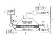
(1)流体を収容するためのチャンバ、
(2)チャンバに結合する真空源、および
(3)チャンバに結合する超音波エネルギー源
を備える装置であって、前記チャンバは、(i)フラットパネル、(ii)入口、および(iii)出口を備え、前記チャンバの前記フラットパネルおよび前記入口は、前記入口を通り前記フラットパネル上を前記出口まで流れる流体が薄膜を形成し、少なくとも前記フラットパネル上の流れの一部の間プラグ流れとして流れるように構成される装置により有効に除染し得ることも発見した。The inventor also, in a twenty-first principal aspect, comprises a fluid comprising a protein-containing biological fluid,
(1) a chamber for containing a fluid;
An apparatus comprising (2) a vacuum source coupled to the chamber, and (3) an ultrasonic energy source coupled to the chamber, the chamber comprising: (i) a flat panel; (ii) an inlet; and (iii) an outlet. The flat panel and the inlet of the chamber such that fluid flowing through the inlet and over the flat panel to the outlet forms a thin film and flows as a plug flow during at least a portion of the flow on the flat panel. It has also been found that decontamination can be effectively performed by an apparatus configured as described above.
本発明者はさらに、第22の主たる態様において、そのような流体を、
(1’)前記流体を収容するための手段、
(2’)前記流体を真空と接触させるための手段、および
(3’)前記流体を収容するための前記手段に超音波エネルギーを導入するための手段
を備える装置であって、前記流体を収容するための前記手段は、(i)前記収容手段に前記流体を導入するための手段、(ii)前記流体を前記収容手段を通って流すための手段、および(iii)前記収容手段から前記流体を除去するための手段を備え、前記収容手段は、前記収容手段を通って流れるタンパク質含有流体が、薄膜を形成し、前記収容手段を通る流れの少なくとも一部の間にプラグ流れとして流れるように構成される装置により有効に除染し得ることを発見した。The inventor further provides, in a twenty-second principal aspect, such a fluid,
(1 ′) means for containing the fluid;
(2 ′) an apparatus comprising means for contacting the fluid with a vacuum, and (3 ′) means for introducing ultrasonic energy into the means for containing the fluid, the apparatus containing the fluid The means for: (i) means for introducing the fluid into the containing means; (ii) means for flowing the fluid through the containing means; and (iii) fluid from the containing means Means for removing the fluid such that the protein-containing fluid flowing through the containing means forms a thin film and flows as a plug flow during at least a portion of the flow through the containing means. It has been discovered that it can be effectively decontaminated by the constructed device.
本発明者はまた、第23の主たる態様において、タンパク質含有生物学的流体を含む流体を
(1)流体を収容するためのチャンバ、
(2)チャンバに結合する真空源、
(3)そのようなチャンバに結合する超音波エネルギー源、および
(4)UV、ガンマ線またはx−線照射源
を備える装置により有効に除染し得ることも発見した。The inventor also provides, in a twenty-third main aspect, a fluid containing a protein-containing biological fluid (1) a chamber for containing the fluid,
(2) a vacuum source coupled to the chamber;
It has also been discovered that it can be effectively decontaminated by an apparatus comprising (3) an ultrasonic energy source coupled to such a chamber, and (4) a UV, gamma or x-ray irradiation source.
本発明者はまた、第24の主たる態様において、タンパク質含有生物学的流体を含む流体を
(1’)前記流体を収容するための手段、
(2’)前記流体を真空と接触させるための手段、
(3’)前記流体を収容するための前記手段に超音波エネルギーを導入するための手段、
(4’)UV、ガンマ線、またはx線照射により前記流体を処理するための手段
を備える装置により有効に除染し得ることを発見した。The inventor also provides, in a twenty-fourth principal aspect, (1 ′) means for containing a fluid comprising a protein-containing biological fluid,
(2 ′) means for contacting said fluid with a vacuum;
(3 ′) means for introducing ultrasonic energy into the means for containing the fluid;
(4 ′) It has been found that it can be effectively decontaminated by an apparatus comprising means for treating the fluid by UV, gamma ray or x-ray irradiation.
本発明者はまた、第25の主たる態様において、タンパク質含有生物学的流体を含む流体を、
(1)流体を収容するためのチャンバ、
(2)チャンバに結合する真空源、
(3)そのようなチャンバに結合する超音波エネルギー源、
(4)オゾン源
を備える装置であって、
前記チャンバは(i)オゾン源からのオゾンを導入するための入口、(ii)血漿を導入するための入口、および(iii)オゾン源からのオゾンを流体と混合するためのデバイスを備える装置により有効に除染し得ることも発見した。The inventor also, in a twenty-fifth principal aspect, comprises a fluid comprising a protein-containing biological fluid,
(1) a chamber for containing a fluid;
(2) a vacuum source coupled to the chamber;
(3) an ultrasonic energy source coupled to such a chamber;
(4) An apparatus including an ozone source,
The chamber comprises an apparatus comprising (i) an inlet for introducing ozone from an ozone source, (ii) an inlet for introducing plasma, and (iii) a device for mixing ozone from the ozone source with a fluid. It has also been found that it can be effectively decontaminated.
本発明者はさらに、第26の主たる態様において、タンパク質含有生物学的流体を含む流体を、
(1’)前記流体を収容するための手段、
(2’)前記流体を真空と接触させるための手段、
(3’)前記流体を収容するための前記手段に超音波エネルギーを導入するための手段、
(4’)オゾンを発生させるための手段
を備える装置であって、
前記流体を収容するための前記手段は(i)前記収容手段にオゾンを発生させるための前記手段からのオゾンを導入するための手段、(ii)前記収容手段に前記流体を導入するための手段、および(iii)オゾンを発生させるための前記手段からの前記オゾンを前記収容手段中の前記流体と混合するための手段を備える装置により有効に除染し得ることも発見した。The inventor further provides, in a twenty-sixth principal aspect, a fluid comprising a protein-containing biological fluid,
(1 ′) means for containing the fluid;
(2 ′) means for contacting said fluid with a vacuum;
(3 ′) means for introducing ultrasonic energy into the means for containing the fluid;
(4 ′) an apparatus comprising means for generating ozone,
The means for containing the fluid is (i) means for introducing ozone from the means for generating ozone in the containing means, and (ii) means for introducing the fluid into the containing means. And (iii) it has also been found that it can be effectively decontaminated by an apparatus comprising means for mixing the ozone from the means for generating ozone with the fluid in the containment means.
本発明者はまた、第27の主たる態様において、タンパク質含有生物学的流体を含む流体を、
(1)流体を収容するためのチャンバ、
(2)チャンバに結合する真空源、
(3)UV、ガンマ線、またはx線照射源、
(4)そのようなチャンバに結合する超音波エネルギー源、
(5)オゾン源
を備える装置であって、前記チャンバは、(i)オゾン源からのオゾンを導入するための入口、(ii)血漿を導入するための入口、および(iii)オゾン源からのオゾンを流体と混合するためのデバイスを備える装置により有効に除染し得ることも発見した。The inventor also in a twenty-seventh principal aspect, comprises a fluid comprising a protein-containing biological fluid,
(1) a chamber for containing a fluid;
(2) a vacuum source coupled to the chamber;
(3) UV, gamma ray or x-ray irradiation source,
(4) an ultrasonic energy source coupled to such a chamber;
(5) an apparatus comprising an ozone source, the chamber comprising: (i) an inlet for introducing ozone from the ozone source; (ii) an inlet for introducing plasma; and (iii) from the ozone source. It has also been discovered that it can be effectively decontaminated by an apparatus comprising a device for mixing ozone with a fluid.
本発明者はさらに、第28の主たる態様において、タンパク質含有生物学的流体を含む流体を、
(1’)前記流体を収容するための手段、
(2’)前記流体を真空と接触させるための手段、
(3’)前記流体をUV、ガンマ線またはx線照射で処理するための手段、
(4’)前記流体を収容するための前記手段に超音波エネルギーを導入するための手段、および
(5’)オゾンを発生させるための手段
を備える装置であって、前記流体を収容するための前記手段は、(i)前記収容手段にオゾンを発生させるための前記手段からオゾンを導入するための手段、(ii)前記収容手段に前記流体を導入するための手段、(iii)オゾンを発生させるための前記手段からの前記オゾンを前記収容手段中の前記流体と混合するための手段を備える装置により有効に除染し得ることも発見した。The inventor further provides, in a twenty-eighth main aspect, a fluid comprising a protein-containing biological fluid,
(1 ′) means for containing the fluid;
(2 ′) means for contacting said fluid with a vacuum;
(3 ′) means for treating the fluid with UV, gamma ray or x-ray irradiation;
(4 ′) an apparatus comprising means for introducing ultrasonic energy into the means for containing the fluid, and (5 ′) means for generating ozone, the apparatus for containing the fluid The means includes (i) means for introducing ozone from the means for generating ozone in the housing means, (ii) means for introducing the fluid into the housing means, and (iii) generating ozone. It has also been discovered that the ozone from the means for causing can be effectively decontaminated by an apparatus comprising means for mixing the fluid in the containment means.
本発明者はさらに、第29の主たる態様において、オゾンを、
(1)下方表面および上方表面を有し、前記下方表面を前記上方表面と接続する複数の通路を有する基板、
(2)前記超音波エネルギーが前記基板の振動により液体に導入されるように前記基板に結合された超音波エネルギー源、
(3)前記基板の前記下方表面に接続されたオゾン源
を備える装置により液体と有効に接触させ得ることも発見した。The inventor further provides ozone in the 29th main aspect,
(1) a substrate having a lower surface and an upper surface and having a plurality of passages connecting the lower surface to the upper surface;
(2) an ultrasonic energy source coupled to the substrate such that the ultrasonic energy is introduced into the liquid by vibration of the substrate;
(3) It has also been discovered that an apparatus comprising an ozone source connected to the lower surface of the substrate can be effectively contacted with a liquid.
本発明のより完全な評価およびその付随する利点の多くは、添付の図面と結びつけて考えるとき以下の詳細な説明を参照してよりよく理解されるようになるので、容易に獲得され得る。 Many of the more complete appraisals of the present invention and its attendant advantages may be readily obtained as they become better understood with reference to the following detailed description when considered in conjunction with the accompanying drawings.
好ましい態様の詳細な説明
すなわち、本発明は、流体を除染するための新規の方法および装置を提供する。ある種の好ましい態様において、流体は、タンパク質含有生物学的流体のような液体である。適切なタンパク質含有生物学的流体には、全血、唾液、精液、脊髄液などのような体液が含まれる。全血に加えて、タンパク質含有生物学的流体は、全血の血漿、血清、および赤血球または血小板画分のような血液製剤であり得る。タンパク質含有生物学的流体はまた、発酵培地のようなさまざまのインビトロまたはインビボのプロセスに由来するいずれかの天然または合成タンパク質含有流体でもあり得る。DETAILED DESCRIPTION OF PREFERRED EMBODIMENTS That is, the present invention provides a novel method and apparatus for decontaminating fluids. In certain preferred embodiments, the fluid is a liquid, such as a protein-containing biological fluid. Suitable protein-containing biological fluids include body fluids such as whole blood, saliva, semen, spinal fluid and the like. In addition to whole blood, protein-containing biological fluids can be blood products such as whole blood plasma, serum, and red blood cell or platelet fractions. The protein-containing biological fluid can also be any natural or synthetic protein-containing fluid derived from various in vitro or in vivo processes such as fermentation media.
本発明の特に好ましい態様において、タンパク質含有生物学的流体は血漿である。本発明の方法および装置は、血漿の除染のコンテキストにおいて主に以下に詳細に検討される。しかしながら、本発明の方法および装置はまた、組換えDNA技術により得られるもののような発酵生成物を含む食品(卵を含む)および反応混合物を含む上記検討されたタンパク質含有生物学的流体を除染するためにも用いられ得ることが理解されるべきである。本発明は、タンパク質含有生物学的流体のみならず、他の熱感受性材料にも同様に適用可能である。特に、以下に検討されるパルス電界(PEF)法は、リンゴジュースを除染するのに有効である。したがって、本発明の方法のコンテキストにおいて、流体は、除染された形態で所望されるいずれの液体でもあり得るし、リンゴジュース、オレンジジュース、トマトジュースなどのようなジュースが含まれる。本発明のコンテキストにおいて、流体と言う用語はまた、通常は液体とは考えられない液体様物質も含む。したがって、本発明の方法および装置はまた、インビトロでの受精(IVF)のための卵などの除染にも適用され得る。本発明の方法はまた、食品にも適用され得るし、その食品は、必ずしもタンパク質を含まなくともよい。同様に、本発明の方法は、特にPEFに関連する汚染の問題が存在するどんな場合でも用いられ得る。 In a particularly preferred embodiment of the invention, the protein-containing biological fluid is plasma. The method and apparatus of the present invention will be discussed in detail primarily below in the context of plasma decontamination. However, the method and apparatus of the present invention also decontaminates the above discussed protein-containing biological fluids containing food products (including eggs) and reaction mixtures containing fermentation products such as those obtained by recombinant DNA technology. It should be understood that it can also be used to The present invention is equally applicable to other heat sensitive materials as well as protein containing biological fluids. In particular, the pulsed electric field (PEF) method discussed below is effective for decontaminating apple juice. Thus, in the context of the method of the present invention, the fluid can be any liquid desired in decontaminated form and includes juices such as apple juice, orange juice, tomato juice and the like. In the context of the present invention, the term fluid also includes liquid-like substances that are not normally considered liquids. Thus, the methods and apparatus of the present invention can also be applied to decontamination of eggs and the like for in vitro fertilization (IVF). The method of the present invention can also be applied to foods, which need not necessarily contain protein. Similarly, the method of the present invention can be used wherever there is a contamination problem, particularly associated with PEF.
処理される血漿は、イヌ、ネコ、ウシ、ウマ、ブタ、チンパンジー、およびヒトのようないずれの哺乳類のものであってもよい。好ましい態様において、除染される血漿は、ヒトの血漿である。 The plasma to be treated can be from any mammal, such as dogs, cats, cows, horses, pigs, chimpanzees, and humans. In a preferred embodiment, the plasma to be decontaminated is human plasma.
除染される血漿は、全血供与または細胞がドナーに戻されるアフェレーシス由来のようないずれか通常の技術により収集され得る。全血供与はドナーから少ない体積(約200ml)を採取することに関与するが、しかし、供与間に相当長い時間(数ヶ月台)を必要とする。アフェレーシスは、ドナーから大きな体積(約600ml)を採取することを含むが、しかし、細胞がドナーに戻されるので、供与間は短い時間(数週間台)を必要とする。血漿の収集は、参照により本明細書に組み込まれるAABB(アメリカ血液銀行協会)新聞技術マニュアル、第13版、バルティモア、メリーランド州、1999年に記載されている。 Plasma to be decontaminated can be collected by any conventional technique, such as from whole blood donation or apheresis where cells are returned to the donor. Whole blood donation involves taking a small volume (about 200 ml) from the donor, but requires a fairly long time (on the order of months) between donations. Apheresis involves taking a large volume (approximately 600 ml) from the donor, but requires a short time (on the order of weeks) between donations as the cells are returned to the donor. Plasma collection is described in the AABB (American Blood Bank Association) Newspaper Technical Manual, 13th edition, Baltimore, Maryland, 1999, incorporated herein by reference.
除染される血漿は、単一のドナーから得られる個人ユニットであり得る。代わりに、除染される血漿は、多数のドナーから採取される対応する多数の個人ユニットをプールすることにより獲得され得る。 The plasma to be decontaminated can be an individual unit obtained from a single donor. Alternatively, decontaminated plasma can be obtained by pooling a corresponding number of individual units taken from a number of donors.
上記のように、血漿を除染する方法は、有用であると考えられる全ての感染因子を除去するかまたは不活性化する必要はない。実際、血漿を除染する多くの方法は、具体的には、例えば外膜を有するウイルスのようなある種のタイプの感染因子のみに対処するように設計されており、いずれも、想定される感染因子でさえ100%の除去または不活性化を保証しない。したがって、本発明のコンテキストにおいて、「血漿を除染する方法」と言う用語は、血漿中に見出される少なくとも1種の感染因子の相当量を除去および/または不活性化することが可能である方法を称する。典型的には、血漿を除染するための本発明の方法は、血漿中に見出される少なくとも1種の感染因子について、少なくとも4、好ましくは少なくとも5、より好ましくは少なくとも6の対数減少率すなわちログ・キル(log kill)を達成することが可能である。 As noted above, the method of decontaminating plasma need not remove or inactivate all infectious agents that may be useful. In fact, many methods of decontaminating plasma are specifically designed to address only certain types of infectious agents, such as viruses with outer membranes, all of which are envisioned Even infectious agents do not guarantee 100% removal or inactivation. Thus, in the context of the present invention, the term “method of decontaminating plasma” is a method that is capable of removing and / or inactivating a substantial amount of at least one infectious agent found in plasma. . Typically, the method of the invention for decontaminating plasma involves a log reduction rate or log of at least 4, preferably at least 5, more preferably at least 6 for at least one infectious agent found in plasma. It is possible to achieve a log kill.
本発明の方法はまた、血漿タンパク質へのダメージを最小化しながら、血漿の除染に作用することも可能である。タンパク質損傷の量は、当該特定タンパク質、用いられる除染方法の特定態様、およびある程度まで供給源および血漿のそれまでの取り扱いに依存する。しかしながら、本発明の方法は、所定のタンパク質を定量するために用いられる許容された実験室的な臨床的方法により定量して、20%未満、10%未満、およびさらに数パーセント台のタンパク質損傷しか引き起こさずに、少なくとも1種の感染因子の上記ログ・キルを達成することが可能である。例えば、フィブリノーゲン濃度を定量するために、既知の量のトロンビンを既知の量の血漿に加え、次いで、凝血形成についての経過時間を測定し、較正された標準に比較する。現代の血液学の実験室においては、この試験および他のタンパク質についての同様の試験は、自動化された装置で日常的に実施され、したがって、タンパク質損傷の程度を定量する正確で文書化された手段を提供する。 The methods of the invention can also affect plasma decontamination while minimizing damage to plasma proteins. The amount of protein damage depends on the particular protein, the particular mode of decontamination method used, and to some extent the source and the previous handling of plasma. However, the method of the present invention is less than 20%, less than 10%, and even a few percent of protein damage, as quantified by accepted laboratory clinical methods used to quantify a given protein. It is possible to achieve the log kill of at least one infectious agent without causing it. For example, to quantify fibrinogen concentration, a known amount of thrombin is added to a known amount of plasma, then the elapsed time for clot formation is measured and compared to a calibrated standard. In modern hematology laboratories, this test and similar tests for other proteins are routinely performed on automated equipment and are therefore an accurate and documented means of quantifying the extent of protein damage. I will provide a.
本発明の方法により除去および/または不活性化され得る感染因子のタイプの例には、寄生虫、細菌、真菌、およびウイルスおよびおそらくプリオンが含まれる。 Examples of types of infectious agents that can be removed and / or inactivated by the methods of the present invention include parasites, bacteria, fungi, and viruses and possibly prions.
それらの感染因子の中で、寄生虫は、熱帯気候で主に顕著な脅威を提起する。そのような危険の最も大きなものはマラリアであり、マラリアは、プラスモディウムのすべての4つの異なる種により広がり、しかし主としてプラスモディウム・マラリアエにより広がる。もう1つの寄生虫による危険は、トリパノソーマ・クルージであり、それは、中南米で深刻な問題であるチャガ病(Chaga’s Disease)を引き起こす。米国では、バベシオーシス(Babesiosis)を引き起こす2種のバベシ原生動物が輸血により感染し得るが、しかしながら、より一般的な経路は、ダニの刺し傷である。ライシュマニア・インファンタムもまた血液製剤中に見出され得る寄生虫である。 Among those infectious agents, parasites pose a major prominent threat in tropical climates. The greatest such danger is malaria, which is spread by all four different species of Plasmodium, but mainly by Plasmodium malariae. Another parasite hazard is Trypanosoma cruzi, which causes Chaga's Disease, a serious problem in Latin America. In the United States, the two Babes protozoa that cause Babesiosis can be infected by blood transfusion, however, the more common route is tick bites. Reishmania inphantam is also a parasite that can be found in blood products.
細菌もまた輸血における今に至る脅威を提示する。この理由のために、CDCおよび血液関係者の主導メンバーは最近、輸血に関連する感染の危険を定量するためのBaCon(細菌汚染)研究に着手した。特に関心の持たれているものは、エリシニア・エンテロコリティカ、エスシェリキア・コリ(大腸菌)、シトロバクター・フロウンディイ、ならびにバルトネラおよびブルーセラの種である。 Bacteria also present an ongoing threat in blood transfusions. For this reason, the lead members of CDC and blood officials recently embarked on a BaCon (bacterial contamination) study to quantify the risk of infection associated with blood transfusions. Of particular interest are Yersinia enterocolitica, Escherichia coli (E. coli), Citrobacter floundii, and Bartonella and Bluesera species.
真菌の感染は、特に、がん治療、HIVなどにより弱体化した免疫系を有する患者のための医療処置において現在も続き、重要性を増している問題である。真菌とかびと言う用語は、しばしば互換性を持つけれども、慣例では、かびとは典型的には成長する真菌のウール状の外観を称するものである。この慣例に従えば、酵母は、この場合、特にサッカロマイセタシー科の特に微細な真菌である。多くのそのような日和見感染が存在するが、臨床的問題のより一般的な媒体の一部は、カンディーダ・アルビカンスおよびカンディーダ・ステラトイデアならびにクリプトコッカス・ネオフォルマンズである。 Fungal infections are a continuing and increasing problem, particularly in medical procedures for patients with immune systems weakened by cancer therapy, HIV, and the like. Although the terms fungus and mold are often interchangeable, by convention, fungi typically refer to the wooly appearance of growing fungi. According to this practice, the yeast is in this case a particularly fine fungus, in particular of the family Saccharomyces. Although many such opportunistic infections exist, some of the more common media for clinical problems are Candida albicans and Candida stellatoidea and Cryptococcus neoformans.
最後に、問題の中心のウイルスは、肝炎(AからE、およびG)、HIV(ヒト免疫欠損ウイルス)、HTLV(ヒトt−細胞リンパ親和性ウイルス)タイプIおよびII、CMV(サイトメガロウイルス)、EBV(エプシュタイン−バーウイルス)およびパーボウイルスB19の様々の菌株である。 Finally, the central viruses in question are hepatitis (A to E and G), HIV (human immunodeficiency virus), HTLV (human t-cell lymphophilic virus) type I and II, CMV (cytomegalovirus) , Various strains of EBV (Epstein-Barr virus) and parvovirus B19.
ほとんどの場合に、上記汚染は、主に、一人の患者から別の患者への輸血における問題である。しかしながら、そのような汚染物についてあらゆる個人の血液を処理し、次いで、この血液を患者に輸血し戻すこともまた可能である。例えば、そのようなアプローチは、エイズ患者の血液中を循環するHIVの負担を軽減する。そのようなアプローチは、非ホジキンスリンパ腫のような血液中の非感染性媒体(「治療技術は、セララックス(Theralux)試行における第1の患者を記録する」、ウォールストリートジャーナル、1/29/01)の治療にも適用され得るであろう。 In most cases, the contamination is mainly a problem in blood transfusion from one patient to another. However, it is also possible to treat any individual's blood for such contaminants and then transfuse this blood back to the patient. For example, such an approach reduces the burden of HIV circulating in the blood of AIDS patients. Such an approach involves non-infectious media in blood such as non-Hodgkins lymphoma ("Therapeutic techniques record the first patient in the Thelarux trial", Wall Street Journal, 1/29 / 01) could also be applied.
血液産業を超えて、他の生物学的分野においてもまたいくつかの用途が存在する。特に、バイオテクノロジーおよび関連する技術において、大きな関心が持ち上がる。背景の問題は、近く発表されるジョイントの保護者薬品協会(PDA)とFDAウイルス除去フォーラムPDA会議ファイル、2001年秋で検討されるであろう。例えば、この産業が直面する1つの問題は、ネズミハイブリドーマは、存在することがどこで見出されようと、ネズミレトロウイルスで汚染されやすいであろうと言うことである。発生する種間交差汚染の可能性は、過去にブタカゼが破滅的な世界的流行病を引き起こしたことを思えば、大問題である。それゆえ、きわめて有効な除染手段は、バイオテクノロジーを発展させるために不可欠である。 Beyond the blood industry, there are also several uses in other biological fields. In particular, there is great interest in biotechnology and related technologies. Background issues will be considered in the upcoming Joint Parental Drug Association (PDA) and FDA Virus Removal Forum PDA Conference File, Fall 2001. For example, one problem facing the industry is that murine hybridomas are likely to be contaminated with murine retroviruses wherever they are found. The potential for cross-species contamination that occurs is a major problem, given the fact that butakase has caused catastrophic pandemics in the past. Therefore, highly effective decontamination means are essential for developing biotechnology.
生物学的分野に加えて、除染技術のための他の用途もまた存在する。1つの主たる領域は食品科学であり、食品科学は、さまざまの汚染物、特にサルモネラのような細菌の有効な除染を必要とする。したがって、食品製品の有効な除染は、安全性を向上させ、保存寿命を延長させる。 In addition to the biological field, there are also other uses for decontamination techniques. One major area is food science, which requires effective decontamination of various contaminants, especially bacteria such as Salmonella. Thus, effective decontamination of food products improves safety and extends shelf life.
処理される対象が通常汚染物であるとみなされない優れた除染技術を用いることの他の可能性もまた存在する。具体的には、インビトロ受精(IVF)の最近の進歩は、雌ドナーから卵細胞を採取し、遺伝物質のほとんどとともに核を除去する可能性を向上させた。次いで、第2の雌からの遺伝物質を卵細胞に挿入し、次いで、実現可能な妊娠を引き起こす意図でそれを受精させる。このアプローチの問題は、ドナーの全ての遺伝物質が除去され得るのではなく、主に一部のミトコンドリアDNAを残すことである。結果として、現れる子供は、実際上も倫理上も大きな問題を引き起こす3者の「親」からの遺伝的寄与を有する。他のタンパク質を本質的に無傷に残しながらドナー遺伝物質の全てを破壊する除染技術を用いることは、そのような問題をなくすであろう。 There are also other possibilities to use good decontamination techniques where the objects to be treated are not normally considered to be contaminants. Specifically, recent advances in in vitro fertilization (IVF) have improved the possibility of harvesting egg cells from female donors and removing the nucleus along with most of the genetic material. The genetic material from the second female is then inserted into the egg cell and then fertilized with the intention of causing a feasible pregnancy. The problem with this approach is that not all the genetic material of the donor can be removed, but mainly leaves some mitochondrial DNA. As a result, the appearing children have genetic contributions from three “parents” that cause significant practical and ethical problems. Using decontamination techniques that destroy all of the donor genetic material while leaving other proteins essentially intact would eliminate such problems.
最後に、以下に記載する独特の装置は、除染以外の目的のためにもまた用いられ得る。特に、オゾン処理ユニットはまた、一般的に、液体にガスを加えるためにも有用である。例えば、医療上の用途の場合には、デバイスは、心肺バイパスの間に血液を酸素化するために用いられ得る。食品および/または工業的用途については、オゾン処理ユニットは、水溶液に二酸化炭素を加えるために用いられ得る。他の同様の適用もまた可能である。 Finally, the unique equipment described below can also be used for purposes other than decontamination. In particular, the ozone treatment unit is also generally useful for adding gas to a liquid. For example, for medical applications, the device can be used to oxygenate blood during cardiopulmonary bypass. For food and / or industrial applications, the ozonation unit can be used to add carbon dioxide to an aqueous solution. Other similar applications are also possible.
I.すなわち、第1の主たる態様において、本発明は、
(a)超音波エネルギーにより血漿を処理すること
を含む血漿を除染するための方法を提供する。I. That is, in the first main aspect, the present invention provides:
(A) To provide a method for decontaminating plasma comprising treating the plasma with ultrasonic energy.
「超音波エネルギー」および「超音波」と言う用語は、ヒトの聴音の上限の20kHzから数百MHzまでの範囲の周波数を有する音波を称する。 The terms “ultrasound energy” and “ultrasound” refer to sound waves having a frequency in the range of 20 kHz to several hundred MHz, the upper limit of human hearing.
いくつかの異なる技術が超音波を発生させるために用いられ得るが、しかし、最も一般的なアプローチは、圧電結晶に電気衝撃を与えることである。次いで、活性化された結晶は、その主軸に沿って膨張収縮し、圧力律動または音波(超音波)を発する。加えて、超音波振動はまた、特に電磁デバイス、電気圧縮デバイス、または磁気圧縮デバイスによる他の通常の手段によっても発生し得る。そのようなデバイスは、参照により本明細書に組み込まれる、公開されたPCT特許出願WO92/20420において記載されている。 Several different techniques can be used to generate ultrasound, but the most common approach is to apply an electrical shock to the piezoelectric crystal. The activated crystal then expands and contracts along its main axis and emits a pressure rhythm or sound waves (ultrasound). In addition, ultrasonic vibrations can also be generated by other conventional means, particularly by electromagnetic devices, electrocompression devices, or magnetic compression devices. Such a device is described in published PCT patent application WO 92/20420, which is incorporated herein by reference.
その比較的高い周波数範囲のために、超音波は、工業および医療において多くの用途を有する。特に、超音波は、液体の処理において多くの独特で有益な用途を有する。 Due to its relatively high frequency range, ultrasound has many applications in industry and medicine. In particular, ultrasound has many unique and beneficial applications in liquid processing.
それらの用途の中で、最も一般的で、最も顕著であるものにキャビテーションが含まれる。キャビテーションは、超音波の低圧部分が液体の蒸気圧未満となる時に起こる局所化された気化である。それらの条件の下では、キャビテーションの泡が成長し、次いで崩壊するとき局所温度および局所圧力は極端に高くなる。 Among those uses, the most common and most prominent is cavitation. Cavitation is localized vaporization that occurs when the low pressure portion of the ultrasound is below the vapor pressure of the liquid. Under these conditions, the local temperature and pressure become extremely high when cavitation bubbles grow and then collapse.
それらの極端な条件は、生物の細胞壁の破裂を含む多くの実際の用途のために用いられる。すなわち、この能力は、特に寄生虫について除染において即座の有用性を有する。波長の制限のために、より少ない程度ではあるが、細菌、真菌およびウイルスのようなより小さな汚染物もまた処理され得る。したがって、処理される液体は、液体を含む全ての非細胞性タンパク質を含む。特に、血液産業においては、処理される液体は、血漿または血清であり、赤血球または血小板ではない。 These extreme conditions are used for many practical applications, including rupture of biological cell walls. That is, this ability has immediate utility in decontamination, especially for parasites. Smaller contaminants such as bacteria, fungi and viruses can also be treated to a lesser extent due to wavelength limitations. Thus, the liquid to be treated includes all non-cellular proteins including liquid. In particular, in the blood industry, the liquid to be processed is plasma or serum, not red blood cells or platelets.
それゆえ、この第1の態様のための全ての構成は、非常に細胞破壊のために用いられるものに非常に似ている。具体的には、超音波源、標的、および超音波源を標的に結合するいくつかの手段の3つの別々の部材が必要とされる。ここでの制限要因は、高周波数波の超音波は空気のようなガス中で良好に伝わらず、それゆえ硬質金属または液体のような伝達媒体を必要とすると言うことである。金属の場合には、導波路は通常アルミニウムで作られている。ホーンと呼ばれる形態に注意深く形成することにより、それらの導波路は、大きな振幅とエネルギーの波を作り出し得るものであり、標的への超音波エネルギーの効率的な移動をもたらす。 Therefore, all configurations for this first aspect are very similar to those used for cell destruction. Specifically, three separate members are required: an ultrasound source, a target, and some means of coupling the ultrasound source to the target. The limiting factor here is that high frequency ultrasonic waves do not propagate well in gases such as air and therefore require a transmission medium such as a hard metal or liquid. In the case of metal, the waveguide is usually made of aluminum. By carefully forming a form called a horn, those waveguides can create waves of large amplitude and energy, resulting in efficient transfer of ultrasonic energy to the target.
この第1の態様における除染技術と現存する細胞破壊技術との間のもう1つの類似点は、両方のユニットが低範囲の超音波周波数で稼動すると言うことである。ここでの基礎となる物理的原理は、水および希釈水性系について、キャビテーションを作り出すために必要とされる力は、100kHzを超えたところで劇的に増加すると言うことである。もちろん、ある程度のキャビテーションはさらに高い周波数でも起こり、本発明の方法は、そのようなより高い周波数の超音波エネルギーを利用し得る。特に、高周波数は、数百kHzからMHz周波数、すなわち「メガソニック」範囲でより多く装置として用いられ、容易に入手可能となることが予想される。 Another similarity between the decontamination technique and the existing cell disruption technique in this first aspect is that both units operate at a low range of ultrasonic frequencies. The underlying physical principle here is that for water and dilute aqueous systems, the force required to create cavitation increases dramatically beyond 100 kHz. Of course, some degree of cavitation occurs at higher frequencies, and the method of the present invention may utilize such higher frequency ultrasonic energy. In particular, the high frequencies are expected to be more readily used as more devices in the hundreds of kHz to MHz frequencies, or “megasonic” range.
それゆえ、本発明の方法の第1の態様において、血漿は、血漿のキャビテーションをもたらすのに十分な周波数を有する超音波エネルギーで処理される。したがって、血漿は、20kHzから10MHz、好ましくは20kHzから1MHz、より好ましくは20kHzから500kHz、さらにより好ましくは20kHzから100kHzの周波数を有する超音波エネルギーで適切に処理される。 Therefore, in the first aspect of the method of the invention, the plasma is treated with ultrasonic energy having a frequency sufficient to cause plasma cavitation. Thus, the plasma is suitably treated with ultrasonic energy having a frequency of 20 kHz to 10 MHz, preferably 20 kHz to 1 MHz, more preferably 20 kHz to 500 kHz, and even more preferably 20 kHz to 100 kHz.
したがって、この第1の態様において記載される除染技術と通常の細胞壁破壊装置との間にある程度の類似が存在するけれども、しかしながら、ある程度の顕著な差異も存在する。具体的には、超音波周波数がしっかりと維持され、キャビテーションが装置のそれぞれの、そして全ての使用の際に実際に起こることは、有効性のため、そして規則的なコンプライアンスのために重要である。それらの条件が合致することを保証するために、プロセスは、好ましくは、ハイドロフォンおよび支持エレクトロニクス(モデルbx−208/308,ppb,Inc.,カリフォルニア州サンディエゴ)の使用によりモニターされねばならない。 Thus, there is some similarity between the decontamination technique described in this first aspect and a normal cell wall disruption device, however, there are also some significant differences. Specifically, it is important for effectiveness and for regular compliance that the ultrasonic frequency is firmly maintained and that cavitation actually occurs during each and every use of the device. . To ensure that these conditions are met, the process should preferably be monitored by the use of hydrophones and supporting electronics (model bx-208 / 308, ppb, Inc., San Diego, Calif.).
新たな除染装置と通常の細胞破壊装置との間のもう1つの顕著な差異は、除染ユニットは、細胞破壊デバイスについて必要とされる保護の程度をはるかに超えるレベルまで所望のタンパク質成分を注意深く保存しなければならないと言うことである。 Another notable difference between the new decontamination device and the normal cell disruption device is that the decontamination unit delivers the desired protein component to a level well beyond the degree of protection required for the cell disruption device. It must be carefully stored.
それらのタンパク質の保護における第1の問題は、超音波キャビテーションにより誘発される強力な化学反応を制限することである。1つのそのような反応は、キャビテーションの間の泡の成長および崩壊による強い攪拌による長鎖有機化合物の破壊である。この破壊は、エルピナーにより記載されているように、(I.E.エルピナー、「超音波の物理的、化学的、および生物学的効果」、コンサルタンツ・ビュロー、ニューヨーク、217ページ、1964年)凝血プロセスに関係する大きくて比較的デリケートなタンパク質について顕著な問題であり得る。 The first problem in protecting these proteins is to limit the strong chemical reactions induced by ultrasonic cavitation. One such reaction is the destruction of long chain organic compounds by vigorous agitation due to bubble growth and collapse during cavitation. This disruption is as described by Elpinner (IE Elpinner, “Physical, Chemical, and Biological Effects of Ultrasound”, Consultants Bureau, New York, p. 217, 1964) It can be a significant problem for large and relatively sensitive proteins involved in the process.
本発明の方法において、血漿タンパク質のそのような損傷は、2つの技術により処理され得る。第1に、処理時間が短く、すなわち5分未満、好ましくは2分未満、より好ましくは30秒未満に維持される。第2に、強度レベルが低く、すなわち、0.1から50W/cm2、好ましくは0.5から10W/cm2およびより好ましくは1から6W/cm2に維持される。もちろん、実際には、それらの技術は、特定のタンパク質溶液および汚染物質に対して調節されねばならない。In the methods of the present invention, such damage of plasma proteins can be handled by two techniques. First, the processing time is kept short, i.e. less than 5 minutes, preferably less than 2 minutes, more preferably less than 30 seconds. Secondly, the intensity level is kept low, i.e. from 0.1 to 50 W / cm <2 >, preferably from 0.5 to 10 W / cm <2 > and more preferably from 1 to 6 W / cm <2 >. Of course, in practice, these techniques must be tailored to specific protein solutions and contaminants.
音波処理を受けるタンパク質溶液に対して完全に破壊的であるもう1つの反応は、キャビテーションの極端な温度と圧力の変化による液体中のフリーラジカルの生成である(V.ミシックおよびP.リース、「EPR分光分析による水系音波化学における1級フリーラジカル種の検出」、「音波化学および音波発光」における、L.A.クラム、T.J.メーソン、J.L.リースおよびK.S.サスリックによる編集、NATO ASIシリーズC、クラウワーアカデミックパブリッシャーズ、ドードレヒト、225〜236ページ、1999年)。それらのラジカルを制限するための好ましい方法は、鎖の破壊を防止するために上記のように超音波処理強度と暴露時間を減少させることである。 Another reaction that is completely destructive to sonicated protein solutions is the generation of free radicals in the liquid due to extreme temperature and pressure changes in cavitation (V. Mythic and P. Reese, “ “Detection of primary free radical species in aqueous sonochemistry by EPR spectroscopy”, “Sonochemistry and sonoluminescence” by LA Clam, TJ Mason, JL Reese and KS Saslick Edit, NATO ASI Series C, Crower Academic Publishers, Dodrecht, 225-236, 1999). A preferred method for limiting these radicals is to reduce the sonication intensity and exposure time as described above to prevent chain breakage.
しかしながら、液体に加えて、フリーラジカルは、処理された液体の表面でも生成し得る。それらのラジカルの中で、最も破壊的なものは、酸素から生成するものである。 However, in addition to the liquid, free radicals can also be generated on the surface of the treated liquid. Among these radicals, the most destructive ones are generated from oxygen.
したがって、この第1の主たる態様の好ましい下位の態様において、超音波エネルギーは、血漿上のガスが不活性雰囲気と置き換えられた後に適用される。この場合には、「不活性」は貴ガスを含まない。というのは、そのような単原子種は、超音波エネルギーを分散させるためにはあまりに小さな程度しか自由度を有さないからである(S.Y.ワン,「超音波源の生物学的影響および特性についてのシンポジウム」において、D.G.ハザードらにより編集される、US Dept.HEW(FDA)78−8948、US政府印刷局、196ページ、1977年)。代わりに、適切な不活性ガスは多原子性でなければならず、特に二酸化炭素である。実際、二酸化炭素ガス層を形成させることは、単に処理される溶液にドライアイスのペレットを投げ込むだけのことである(高強度超音波処理装置使用者案内、ソニックス&マテリアルズ社、ニュートン、コネティカット州、1999年)。放出されるガスは、この場合、酸素に置き換わり、酸素がないため、酸素ラジカルは生成し得ない。 Thus, in a preferred sub-embodiment of this first main aspect, the ultrasonic energy is applied after the gas on the plasma has been replaced with an inert atmosphere. In this case, “inert” does not include a noble gas. This is because such monoatomic species have a degree of freedom that is too small to disperse ultrasonic energy (SY Wan, “Biological effects of ultrasonic sources” And US Dept. HEW (FDA) 78-8948, US Government Printing Bureau, 196 pages, 1977) edited by DG Hazard et al. Instead, a suitable inert gas must be polyatomic, in particular carbon dioxide. In fact, forming a carbon dioxide gas layer is simply throwing dry ice pellets into the solution being processed (high intensity sonicator user guide, Sonics & Materials, Newton, Connecticut) 1999). In this case, the released gas is replaced with oxygen, and since there is no oxygen, oxygen radicals cannot be generated.
このプロセスの間に、溶解したガスの一部もまた二酸化炭素により置き換わる。この置換の一部は、ペレットのすぐ近辺の濃度勾配により起こるが、しかし、この置換のほとんどは、液体表面上の富化された二酸化炭素ガス層からの輸送による。いずれの場合でも、正味の結果は、酸素の優先的な除去であり、そのことはやはり有益である。というのは、酸素ラジカルは、タンパク質に対して非常に破壊的であるからである。したがって、全てのプロセスはhplcで通常用いられるヘリウム散布技術に類似することに注意されたい。しかし、ヘリウムは、上記貴ガスラジカルの生成のためにここでは用いられ得ない。 During this process, some of the dissolved gas is also replaced by carbon dioxide. Some of this substitution occurs due to the concentration gradient in the immediate vicinity of the pellet, but most of this substitution is due to transport from the enriched carbon dioxide gas layer on the liquid surface. In any case, the net result is a preferential removal of oxygen, which is still beneficial. This is because oxygen radicals are very destructive to proteins. Therefore, it should be noted that all processes are similar to the helium sparging technique normally used in hplc. However, helium cannot be used here for the generation of the noble gas radicals.
フリーラジカルの生成の制御に加えて、タンパク質損傷を制限する上でのもう1つの重要な問題は、主に超音波源からの過剰な熱の制御である。この制御を達成するために、いくつかの冷却手段を備えねばならない。超音波源の熱を制限する好ましい手段は、超音波源および/またはホーンに水の流れを与えることである。標的を冷却するための好ましい手段は水浴に浸すことであり、このことはまた、超音波ホーンおよび超音波源への強力な音響学的結合も生み出す。 In addition to controlling the generation of free radicals, another important issue in limiting protein damage is mainly the control of excess heat from the ultrasound source. In order to achieve this control, several cooling means must be provided. A preferred means of limiting the heat of the ultrasound source is to provide a stream of water to the ultrasound source and / or horn. A preferred means for cooling the target is to immerse in a water bath, which also creates a strong acoustic coupling to the ultrasonic horn and the ultrasonic source.
したがって、それらの技術によれば、いずれかの選択された温度に標的を維持することが可能である。しかしながら、この温度は、しばしば対立する問題に依存する。具体的には、タンパク質、特に第VIII因子のような凝血因子は典型的には熱感受性である。それゆえ、最大限の保護のために、温度は、2から10℃のFDA特定範囲内に比較的低く保たれるべきである。他方、水中、または希釈水系中のキャビテーションは、約50℃で最も有効である(J.ブリッツ、「超音波学:方法と用途」、ザ・バターワース・グループ、ロンドン、133〜4ページ、1971年)。この温度では、泡形成を誘発するためには最少量のエネルギーしか要求されず、より少ないエネルギーでは、たんぱく質鎖破壊はより少なく、ラジカル形成はより少ない。加えて、高温では溶解するガスはより少なく、それにより、上記のように最も破壊的である酸素ラジカルの形成をさらに減少させる。 Thus, according to those techniques, it is possible to maintain the target at any selected temperature. However, this temperature often depends on conflicting problems. Specifically, proteins, particularly clotting factors such as Factor VIII, are typically heat sensitive. Therefore, for maximum protection, the temperature should be kept relatively low within the FDA specific range of 2 to 10 ° C. On the other hand, cavitation in water or in dilute water systems is most effective at about 50 ° C. (J. Blitz, “Ultrasonics: Methods and Applications”, The Butterworth Group, London, pages 133-4, 1971. ). At this temperature, a minimal amount of energy is required to induce foam formation, with less energy there is less protein chain breakage and less radical formation. In addition, less gas dissolves at high temperatures, thereby further reducing the formation of oxygen radicals, which are the most destructive as described above.
それらの理由のために、もし標的がそのような高温に耐え得るならば、ユニットは、約50℃で操作されるべきである。特に、さらに高い温度に耐え得るタンパク質については、最も高い可能な範囲の使用は、付加的な安全性の尺度である病原の熱による不活性化を提供する。この場合には、50℃をわずかに超える温度は、キャビテーション効率のある程度の減少をもたらし得るが、しかし、これは、熱による不活性化で得られる改善により、相殺を超えるものが得られる。代わりに、さらに高い除染温度は分離工程として用いられ得るものであり、キャビテーションは、より低い50℃程度でなされる。 For those reasons, the unit should be operated at about 50 ° C. if the target can withstand such high temperatures. In particular, for proteins that can withstand higher temperatures, the highest possible range of use provides pathogenic heat inactivation, an additional measure of safety. In this case, temperatures slightly above 50 ° C. can lead to some reduction in cavitation efficiency, but this is more than offset by the improvement obtained with thermal inactivation. Instead, higher decontamination temperatures can be used as a separation step, and cavitation is done at the lower 50 ° C.
あまり強固でない物質については、液体は、処理の直前まで冷却されたままにすべきであり、その時点で、急速な加熱技術が、50℃以下まで操作温度を上昇させるように小さな試料に適用されるべきである。この時点で、超音波は、可能な限り短い持続時間と強度で適用されるべきであり、次いで、試料は、貯蔵温度まで急速に冷却される。 For less rigid materials, the liquid should remain cooled until just prior to processing, at which time rapid heating techniques are applied to the small sample to raise the operating temperature to below 50 ° C. Should be. At this point, the ultrasound should be applied with the shortest possible duration and intensity, and then the sample is rapidly cooled to the storage temperature.
最後に、上昇した温度に最小限の時間でさえ耐え得ない試料については、音波処理は、最も高い許容し得る温度で実施されるべきであり、続いて、超音波源またはキャビテーションプロセスに由来する残留熱を除去するために急速に冷却する。 Finally, for samples that cannot tolerate elevated temperatures even for a minimum amount of time, sonication should be performed at the highest acceptable temperature, followed by an ultrasonic source or cavitation process Cool rapidly to remove residual heat.
したがって、それら3つの全てのプロセスは、有効な熱移動のためのある種の手段を必要とする。上昇温度に耐え得る物質については、実際にそのような温度を達成するためのいくつかの加熱の選択肢が存在する。長時間の加熱に耐え得る強固な物質については、供給源バッグまたは容器全体が暖められ得るし、所望の上昇温度に維持され得る。水浴浸漬、マイクロ波、空気送風、またはいずれか他の簡便な技術がこの加温のために用いられ得る。 Therefore, all three of these processes require some kind of means for effective heat transfer. For materials that can withstand elevated temperatures, there are actually several heating options to achieve such temperatures. For strong materials that can withstand prolonged heating, the source bag or the entire container can be warmed or maintained at the desired elevated temperature. Water bath immersion, microwaves, air blast, or any other convenient technique can be used for this warming.
より温度感受性の物質の急速な加熱のためには、処理される体積は、まず、より小さなユニットかまたは単位時間流れあたり連続的な少ない体積に小分けされる。次いで、それらのより小さなユニットまたは流れは、それらが水浴、マイクロ波、空気送風など由来のようないずれか簡便な熱源からの熱移動に供される大表面積を有する分離したバッグを通過する。 For rapid heating of more temperature sensitive materials, the volume to be treated is first subdivided into smaller units or continuous smaller volumes per unit time stream. Those smaller units or streams then pass through a separate bag with a large surface area where they are subjected to heat transfer from any convenient heat source such as from a water bath, microwave, air blast or the like.
同様なアプローチは、急速な冷却のために用いられる。しかしながら、この場合には、適切な冷却機構は、水浴浸漬またはガス膨張もしくはペルティエ効果により冷却されるプレートとの接触である。 A similar approach is used for rapid cooling. However, in this case, a suitable cooling mechanism is contact with a plate cooled by water bath immersion or gas expansion or Peltier effect.
第1の主たる態様の方法は、バッチ式、半連続式または連続式のいずれかで実施され得ることもまた理解されるべきである。バッチ式除染については、単一バッグユニットは、超音波エネルギーにより個別に処理され得る。代わりに、半連続操作においては、血漿の単一ユニットまたは個々の小さな体積は、それらが超音波エネルギーで処理される1以上のステーションまたはステージを通過して流れ得る。この操作モードでは、それぞれの個々のユニットまたは体積は、処理のためのそれぞれのステーションまたはステージで保持され、次いで、次のステーションまたはステージにバルクで通過する。さらにもう1つの代替法は、血漿がステーションまたはステージを中断無しに流動し得る連続操作である。半連続モードおよび連続モードの両方は、処理される物質の極めて大きなプールを含む分別または他のプロセスに適用し得る。 It should also be understood that the method of the first main aspect can be carried out either batchwise, semi-continuously or continuously. For batch decontamination, a single bag unit can be individually treated with ultrasonic energy. Alternatively, in semi-continuous operation, a single unit or individual small volume of plasma can flow through one or more stations or stages where they are treated with ultrasonic energy. In this mode of operation, each individual unit or volume is held at each station or stage for processing and then passed in bulk to the next station or stage. Yet another alternative is a continuous operation where plasma can flow through the station or stage without interruption. Both semi-continuous mode and continuous mode can be applied to fractionation or other processes involving very large pools of processed materials.
実際には全てのそれらの異なるモードの操作を達成するために、特別な処理チャンバが必要とされる。 In practice, a special processing chamber is required to achieve all these different modes of operation.
このチャンバについての第1の条件は、入口管はあらゆる病原を含んではならないと言うことである。背後の問題は、入口管が容器の頂部接合中のポートを通過する通常の血液バッグで見られ得る。それ自体、この管にとどまる処理されていない流体は、続いて、処理された流体を汚染し得る。これは、超音波および以下に記載される他の処理技術にとって特別な問題である。というのは、そのような処理プロセスが終わった後、病原の循環を防止するために残留物質は流体中にとどまらないからである。 The first condition for this chamber is that the inlet tube must not contain any pathogens. The problem behind can be seen in a normal blood bag where the inlet tube passes through the port in the top joint of the container. As such, the unprocessed fluid that remains in this tube can subsequently contaminate the processed fluid. This is a particular problem for ultrasound and other processing techniques described below. This is because after such treatment process is over, residual material does not stay in the fluid to prevent pathogenic circulation.
この問題を防止するために、入口管はバッグに近接して熱シールされ得るものであるが、しかしこのアプローチはいまだポートを残し、このポートは、シールすることが比較的困難である。そのようなポートも狭いので、したがって超音波は管のオリフィスの狭い管直径の中で効果的に減衰し、それにより、管の長さ全体でいずれかの病原についてほとんどまたはまったく処理されていない部分を残す。 To prevent this problem, the inlet tube can be heat sealed close to the bag, but this approach still leaves a port that is relatively difficult to seal. Since such ports are also narrow, the ultrasound is therefore effectively attenuated within the narrow tube diameter of the tube orifice, so that the entire length of the tube has little or no treatment for any pathogens. Leave.
バッチ処理のための単純な代替案は、管のオリフィスの下でバッグそれ自体を熱シールすることである。有効なシーリングのために、この手順は、液体が、バッグの外的圧縮によりシーリングゾーンからすでに吐き出されたときに実施されねばならない。 A simple alternative for batch processing is to heat seal the bag itself under the orifice of the tube. For effective sealing, this procedure must be performed when the liquid has already been expelled from the sealing zone by external compression of the bag.
半連続プロセスについては、修正圧縮アプローチが好ましい。この場合には、上記のように、処理チャンバは管のオリフィスの直下できつくクランプ固定されるが、しかし、この場合には、熱シールは用いられない。代わりに、チャンバ中の流体は処理され、ついで、流体の次のバッチがクランプを緩めることにより流入を許容される前に排出される。流体体積、具体的には、クランプ近くの流体の完全な処理を保証するために、クランプジョーの面は、アルミニウムまたはステンレス鋼で作られ、それによりクランプでの音波の消音を防止する。他方、中実な金属クランプジョーは、音波をクランプを通して入力容器に伝播させ、したがっておそらく、過剰な音響処理を引き起こす。この潜在的問題を防止するために、クランプジョーの背面は、ゴムまたは他の防音材で被覆される。 For semi-continuous processes, a modified compression approach is preferred. In this case, as described above, the processing chamber is clamped directly below the tube orifice, but in this case, no heat seal is used. Instead, the fluid in the chamber is processed and then drained before the next batch of fluid is allowed to enter by loosening the clamp. In order to ensure a complete treatment of the fluid volume, in particular the fluid near the clamp, the face of the clamp jaw is made of aluminum or stainless steel, thereby preventing sound attenuation at the clamp. On the other hand, a solid metal clamp jaw propagates sound waves through the clamp to the input container, thus possibly causing excessive acoustic processing. To prevent this potential problem, the back surface of the clamp jaw is coated with rubber or other soundproofing material.
連続ユニットはそのような変更を必要としないことに注意されたい。というのは、流れは、漸進的に処理されるからである。 Note that continuous units do not require such changes. This is because the flow is processed progressively.
処理チャンバについての第2の条件は、液体層は、比較的薄くなければならないと言うことである。そのような薄い液体層にはいくつかの利点が存在する。第1に、薄層は、均一温度と均一冷却を保証するために必要である。加えて、薄層はまた、液体中で発生する気泡が表面に急速に上昇することも可能とする。このことは重要である。というのは、急速な泡の上昇は、超音波が強力な泡の表面振動または強力な泡の周りのスリップ流れを誘発し得る時間を減少させ、それによりタンパク質損傷を減少させるからである。さらに、急速な泡の上昇はまた、過剰なサイズへの泡の集中も防止する。そのような大きな泡と比較して、小さな泡は好ましい。というのは、それは、より均一な処理を提供し、より少ない表面振動およびスリップ流れを有するからである。 The second condition for the processing chamber is that the liquid layer must be relatively thin. There are several advantages to such a thin liquid layer. First, a thin layer is necessary to ensure uniform temperature and uniform cooling. In addition, the thin layer also allows bubbles generated in the liquid to rise rapidly to the surface. This is important. This is because rapid bubble rise reduces the time that ultrasound can induce strong bubble surface vibrations or slip flow around strong bubbles, thereby reducing protein damage. Furthermore, the rapid bubble rise also prevents the concentration of bubbles to excessive size. Small bubbles are preferred compared to such large bubbles. This is because it provides a more uniform treatment and has less surface vibration and slip flow.
それゆえ、実際には、血漿は、好ましくは、超音波エネルギーの適用の少なくともある程度の時間の間、2から20mm、好ましくは2から10mm、およびより好ましくは2から4mmの厚さを有する薄膜に形成される。好ましくは、血漿は、超音波エネルギーの適用の開始の前にそのような薄膜に形成され、超音波エネルギーの全的適用の間そのような薄膜に維持される。 Thus, in practice, the plasma is preferably in a thin film having a thickness of 2 to 20 mm, preferably 2 to 10 mm, and more preferably 2 to 4 mm for at least some time of application of ultrasonic energy. It is formed. Preferably, plasma is formed in such a thin film before the start of application of ultrasonic energy and is maintained in such a thin film during the entire application of ultrasonic energy.
他方、適切な処理体積を獲得するためには、それらの薄層は、相対的に広くなければならない。バッチモードまたは半連続モードの場合には、広い表面は、得られる体積全体が超音波により均一に処理され得る限り円、正方形などのようないずれかの所望の形態のものであり得る。ここでの制限要因は、超音波は、典型的には、水の容器の中で均一暴露を生み出さないと言うことである。この理由のために、超音波洗浄産業は、主に、狭い帯域幅にわたって混合された周波数を用いることにより、および共鳴定在波を回避する寸法に処理タンクを建設することにより、「ホット」スポットおよび「コールド」スポットを回避するための多数の方法を開発した。それらのアプローチは、バッチおよび半連続除染ユニットのために直接用いられ得る。しかしながら、除染デバイス中の液体層は、超音波クリーナーのために通常用いられるものよりはるかに浅い。 On the other hand, in order to obtain a suitable processing volume, the thin layers must be relatively wide. In the case of batch mode or semi-continuous mode, the wide surface can be of any desired form, such as circles, squares, etc. as long as the entire volume obtained can be treated uniformly by ultrasound. The limiting factor here is that ultrasound typically does not produce uniform exposure in water containers. For this reason, the ultrasonic cleaning industry has mainly "hot" spots by using mixed frequencies over a narrow bandwidth and by constructing processing tanks to dimensions that avoid resonant standing waves. And developed a number of methods to avoid “cold” spots. Those approaches can be used directly for batch and semi-continuous decontamination units. However, the liquid layer in the decontamination device is much shallower than that normally used for ultrasonic cleaners.
しかしながら、それらのアプローチは、連続流システムで要求される独特の形態に適合するように修正されねばならない。ここでの目標は、流れる流体の均一処理を保証することである。問題は、動く流体は、いくつかの異なる流動パターンに従い得ると言うことである。川、ゆっくりと動く管の流れなどのような共通の経験において、層流は、流体の中心で急速に動き、一方、境界近くの流体は本質的に静止状態にあるように展開する。展開するのは非常に単純であるけれども、そのような流れは除染作業では回避されねばならない。というのは、チャンバ壁近くの流体はそのように過剰な処理を受け、一方、中心の流体は、本質的に処理されないであろうからである。 However, these approaches must be modified to fit the unique configuration required for continuous flow systems. The goal here is to ensure a uniform treatment of the flowing fluid. The problem is that moving fluids can follow several different flow patterns. In common experiences such as rivers, slow moving tube flows, etc., laminar flow moves rapidly at the center of the fluid, while the fluid near the boundary develops to be essentially stationary. Although it is very simple to deploy, such a flow must be avoided in the decontamination operation. This is because the fluid near the chamber wall will be so overtreated while the central fluid will be essentially untreated.
この問題を回避する1つの手段は、渦の流れが流体の徹底的なバルク混合をもたらすように荒い流れを用いることである。不運にも、このアプローチは、いくつかの理由のためにタンパク質除染にとって適切ではない。第1に、レイノルズ数Re=(ρVd/μ)(式中、ρは密度であり、Vは速度であり、dは直径であり、μは粘度である)は、開放された頂部流動チャンネルについて約1000でなければならない。それ自体、極端に高い流動速度は、乱流を達成するために用いられねばならないが、しかし、実際にそのような速度を獲得することは非常に困難である。さらに、たとえそのような速度が達成され得ても、許容し得る処理時間を生み出すためには、極めて長い処理装置が必要とされるであろう。最後に、たとえ高速で長い滞留時間のチャンバを作り得ても、得られる長時間の乱流はデリケートなタンパク質を損傷し、したがって、そのようなデバイスの利用範囲を限定してしまうであろう。それらの理由のために、乱流混合は、ほとんどのタンパク質除染作業にとって適切ではない。 One means to avoid this problem is to use a rough flow so that the vortex flow results in thorough bulk mixing of the fluid. Unfortunately, this approach is not appropriate for protein decontamination for several reasons. First, the Reynolds number Re = (ρVd / μ), where ρ is the density, V is the velocity, d is the diameter, and μ is the viscosity for the open top flow channel. Must be about 1000. As such, extremely high flow velocities must be used to achieve turbulence, but in practice it is very difficult to achieve such velocities. Furthermore, even if such speeds can be achieved, very long processing equipment will be required to produce acceptable processing times. Finally, even if high speed and long residence time chambers can be created, the resulting long turbulence will damage sensitive proteins and thus limit the range of use of such devices. For those reasons, turbulent mixing is not appropriate for most protein decontamination operations.
代替策は、全ての流体が処理装置を通してバルクとして動く、プラグ流れを用いることである。そのような流れを発生させるために、入口管を通って流入する流体はまず拡散装置と呼ばれる膨張セクションを通して広げられる。この拡散装置の出口で、プラグ流れ領域を提供するために長方形の形態が用いられる。例えば、この領域は、30cm幅、60cm長であり、0.4cmの流体深さを有する。ついで、この長方形部材の末端で、本質的に逆転攪拌装置である集中セクションが出口管への流れを誘導するために用いられる。この単純な形態は、紫外線流動セルおよび同様の一般的な実験室設備において用いられる。 An alternative is to use a plug flow where all the fluid moves as a bulk through the processing equipment. In order to generate such a flow, the fluid entering through the inlet tube is first spread through an expansion section called a diffuser. At the outlet of the diffuser, a rectangular form is used to provide a plug flow area. For example, this region is 30 cm wide, 60 cm long, and has a fluid depth of 0.4 cm. Then, at the end of this rectangular member, a concentrated section, essentially a reverse stirrer, is used to direct the flow to the outlet tube. This simple form is used in UV flow cells and similar general laboratory equipment.
除染用途のために、超音波源は、長方形セクションの下に直接配置される。このアプローチによれば、超音波は、除染をもたらすのみならず、流体の有効粘度も減少させ得る。この粘度の減少は重要である。と言うのは、低粘度は、プラグ流れが層状になる傾向を減少させ、このことは、いくつかのチャンバの流れの直径について起こり得るからである。それゆえ、この形態の正味の結果は、流体のまったく均一な超音波処理である。 For decontamination applications, the ultrasound source is placed directly under the rectangular section. According to this approach, ultrasound can not only provide decontamination, but also reduce the effective viscosity of the fluid. This reduction in viscosity is important. This is because the low viscosity reduces the tendency of the plug flow to stratify, which can occur for several chamber flow diameters. The net result of this form is therefore a completely uniform sonication of the fluid.
II. 第2の主たる態様において、本発明は、
(a’)超音波エネルギーにより血漿を処理するための工程
を含む血漿を除染するための方法を提供する。この第2の主たる態様において、工程(a’)「超音波エネルギーによる血漿の処理のための」とは、工程「(a)超音波エネルギーにより血漿を処理すること」が第1の主たる態様のコンテキストにおいて実施されるのと同じ方式で実施され得る。II. In a second main aspect, the present invention provides:
(A ′) A method for decontaminating plasma comprising the step of treating the plasma with ultrasonic energy. In this second main aspect, the step (a ′) “for treatment of plasma with ultrasonic energy” means that the step “(a) treatment of plasma with ultrasonic energy” is the first main aspect. It can be implemented in the same way that it is implemented in context.
III. 第3の主たる態様において、本発明は、
(a)流体を脱ガスしながら超音波エネルギーにより流体を処理すること
を含む流体を除染するための方法を提供する。III. In a third principal aspect, the present invention provides:
(A) A method is provided for decontaminating a fluid comprising treating the fluid with ultrasonic energy while degassing the fluid.
したがって、この第3の主たる態様において、超音波エネルギーの適用の間流体に真空が適用される。 Thus, in this third main aspect, a vacuum is applied to the fluid during application of ultrasonic energy.
この第3の主たる態様において、超音波エネルギーは、フリーラジカルを防除する手段を除いて、第1と第2の態様のコンテキストにおいて上記の同じ設備を用いて流体に適用され得る。具体的には、第1と第2の主たる態様の1つの好ましい態様において、超音波エネルギーは、血漿上のガスが不活性雰囲気により置換された後に適用される。非常に有効であるけれども、このアプローチは、不運にも、無菌の消耗品のための材料コストと系の汚染を許容しないでそれらの材料を導入する問題が絡んでくる。 In this third main aspect, ultrasonic energy can be applied to the fluid using the same equipment described above in the context of the first and second aspects, except for means for controlling free radicals. Specifically, in one preferred embodiment of the first and second main embodiments, the ultrasonic energy is applied after the gas on the plasma is replaced by an inert atmosphere. Although very effective, this approach unfortunately involves the cost of materials for sterile consumables and the problem of introducing those materials without allowing system contamination.
別のアプローチは、超音波で処理される液体上のガスを除去するために真空を適用することである(「高強度超音波処理装置使用者案内」、ソニックス&マテリアルズ社、コネチカット州ニュートン、1999年参照)。この第3の主たる態様において、除染される液体は、上記流体のいずれかであり得る。好ましい態様において、流体は、血漿のようなタンパク質含有生物学的流体である。以下の検討は、血漿のコンテキストにおいて方法を説明するが、しかし、方法は、上記流体のいずれに対しても適用され得ることが理解されるべきである。 Another approach is to apply a vacuum to remove gas on the liquid to be treated with ultrasound ("High-Intensity Sonication Equipment User Guide", Sonics & Materials, Newton, Connecticut, 1999). In this third main aspect, the liquid to be decontaminated can be any of the above fluids. In a preferred embodiment, the fluid is a protein-containing biological fluid such as plasma. The following discussion describes the method in the context of plasma, but it should be understood that the method can be applied to any of the above fluids.
流体上のガスは、流体上のガスに約2から100mbar、好ましくは約10から80mbar、より好ましくは20から60mbarの真空を適用することにより有効に除去される。ここでの制限要因は、溶媒の蒸発である。十分に低い圧力で、液体は制御不可能に沸騰し得る。異なる液体は異なるレベルの真空を要求し得るので、真空のレベルが変化し得るように装置が成形されることが好ましい。 The gas on the fluid is effectively removed by applying a vacuum of about 2 to 100 mbar, preferably about 10 to 80 mbar, more preferably 20 to 60 mbar to the gas on the fluid. The limiting factor here is evaporation of the solvent. At sufficiently low pressure, the liquid can boil uncontrollably. Since different liquids may require different levels of vacuum, it is preferred that the device be shaped so that the level of vacuum can vary.
真空は、真空ポンプにより適用され得る。油の汚染を回避するために、真空ポンプは、スクロールかまたは他の乾燥した排気方法を使用するべきである。 The vacuum can be applied by a vacuum pump. To avoid oil contamination, the vacuum pump should use scroll or other dry exhaust methods.
真空は、少なくとも血漿への超音波エネルギーの適用の開始の時間に、流体、例えば血漿上のガスに適用されることが好ましい。より好ましくは、真空は、血漿への超音波エネルギーの適用の開始の前に血漿上のガスに適用される。さらにより好ましくは、真空は、(1)血漿への超音波エネルギーの適用の開始の前に、そして(2)血漿への超音波エネルギーの少なくとも一部の適用の間に血漿上のガスに適用される。もちろん、超音波エネルギーは、真空への暴露の中断の後の適用され続け得る。 A vacuum is preferably applied to the fluid, for example a gas on the plasma, at least at the start of the application of ultrasonic energy to the plasma. More preferably, the vacuum is applied to the gas on the plasma prior to the start of application of ultrasonic energy to the plasma. Even more preferably, the vacuum is applied to the gas on the plasma (1) before the start of the application of ultrasonic energy to the plasma and (2) during the application of at least a portion of the ultrasonic energy to the plasma. Is done. Of course, ultrasonic energy may continue to be applied after interruption of exposure to vacuum.
液体−ガス界面での酸素ラジカルの形成の消去を超えて、この真空技術はまた、タンパク質溶液の除染において付加的な利点も有する。 Beyond eliminating the formation of oxygen radicals at the liquid-gas interface, this vacuum technique also has additional advantages in the decontamination of protein solutions.
そのような主たる利点は、適用される真空は、液体上の蒸気圧を減少させ、それによりキャビテーションを誘導するのに必要とされるエネルギーを減少させることである。適用されるエネルギーがより少ないと、第1の態様および第2の態様において上述されたように起こり得るように望ましからぬタンパク質損傷は少なくなる。 The main advantage of such is that the applied vacuum reduces the vapor pressure over the liquid, thereby reducing the energy required to induce cavitation. The less energy applied, the less unwanted protein damage can occur as described above in the first and second aspects.
除染系への真空の適用のもう1つの利点は、超音波処理の際の液体の急速で有効な脱ガスである。超音波の最も単純な適用であると一般的にみなされるように(T.J.メーソン、「音響化学および出力超音波学の工業的適用」、「音響化学および音響発光」、L.A.クラム、T.J.メーソン、J.L.ライスおよびK.S.サスリック編集、NATO ASIシリーズC、クラウワー・アカデミック・パブリッシャーズ、ドードレヒト、385ページ、1999年)、脱ガスは、ソーダおよびビール製造(「マークスの機械技術者のための標準ハンドブック」、第10版、マグローヒル、ニューヨーク、12_121−12_123、1996年)からhplcオイル洗浄までの範囲の産業で用いられる。それらのおよび同様の用途において、目標は、液体製品に溶解するガスの少なくとも一部を除去することである。 Another advantage of applying a vacuum to the decontamination system is the rapid and effective degassing of the liquid during sonication. As generally regarded as the simplest application of ultrasound (TJ Mason, “Industrial application of sonochemistry and output ultrasound”, “Acoustochemistry and sonoluminescence”, LA. Clam, TJ Mason, JL Rice and KS Saslick, NATO ASI Series C, Crawler Academic Publishers, Dordrecht, 385 pages (1999), degassing, soda and beer production ("Standard Handbook for Marks Mechanical Engineers", 10th edition, McGraw Hill, New York, 12_121-12_123, 1996) and used in industries ranging from hplc oil cleaning. In these and similar applications, the goal is to remove at least a portion of the gas that dissolves in the liquid product.
液体の音波処理に関わるガスの実質的に2つの源泉が存在することに注意することは重要である。一般的な検討は、米国特許第4,597,876号において提供されている。放出される第1のガスは、「精留拡散」または「ガス性キャビテーション」と称されるプロセスで溶解しているガスである。この場合において、溶解するガスは、単純に、大きくなる泡に捉えられる。と言うのは、ガスは、液体に戻って拡散し得るよりも急速に溶液から吐き出されるからである。逆に、音響化学文献において、「キャビテーション」または「蒸気キャビテーション」とよりしばしば呼ばれるプロセスは、音波を掛けられた液相それ自体からの泡の形成に言及する。エネルギーの観点では、精留拡散は、ソーダカンを振ることにより容易に例証されるように、単に強力な振動のみを必要とする。しかしながら、通常キャビテーションと呼ばれるものを産み出すために液体を気化させるためには、はるかに大きなエネルギーが要求される。その結果、音響化学系および様々の超音波洗浄装置はまず拡張された操作および/または実際の処理の前の様々の添加剤(石鹸)の使用により「脱ガスされ」、さもなければ、溶解したガスは、音波を「軟化し」、したがって、超音波デバイスの性能を低下させる。 It is important to note that there are essentially two sources of gas involved in sonication of liquids. A general discussion is provided in US Pat. No. 4,597,876. The first gas released is a gas that is dissolved in a process called “rectifying diffusion” or “gas cavitation”. In this case, the dissolved gas is simply captured by the growing bubbles. This is because the gas is expelled from the solution more rapidly than it can diffuse back into the liquid. Conversely, in the sonochemical literature, a process more often referred to as “cavitation” or “vapor cavitation” refers to the formation of bubbles from the sonicated liquid phase itself. From an energy point of view, rectifying diffusion only requires strong vibrations, as easily illustrated by shaking sodakan. However, much more energy is required to vaporize the liquid to produce what is commonly called cavitation. As a result, sonochemical systems and various ultrasonic cleaning devices are first “degassed” or otherwise dissolved by extended operation and / or use of various additives (soaps) prior to actual processing. The gas “softens” the sound waves, thus reducing the performance of the ultrasonic device.
もちろん、長い操作時間も石鹸も除染作業のためには許容され得ない。結果として、血漿に十分なエネルギーの音波を適用することは、精留拡散と水のキャビテーションの組み合わせをもたらす。さらに、精留拡散は、溶解しているガスをキャビテーションにより形成される泡にし得る。しかしながら、第1と第2の態様に記載されているように、タンパク質損傷を制限するために、超音波への暴露を可能な限り少なく維持することが望ましい。それらの条件の下で、比較的少ないガスの発生が、いずれかの源泉から起こる。 Of course, neither long operating time nor soap is acceptable for decontamination work. As a result, applying sound waves of sufficient energy to plasma results in a combination of rectification diffusion and water cavitation. Furthermore, rectifying diffusion can turn dissolved gas into bubbles formed by cavitation. However, as described in the first and second aspects, it is desirable to keep the exposure to ultrasound as low as possible to limit protein damage. Under those conditions, relatively little gas evolution occurs from either source.
逆に、真空を適用することは、蒸気圧を減少させ、したがって、両方の源泉からの気泡の成長を非常に加速する。加えて、真空はまた、表面に達するいずれの気泡も除去する。正味の結果は、ほとんど溶存ガスのない液体であり、特に、このように、液体はほとんど溶存酸素を有さない。この酸素濃度の減少は、キャビテーションによる酸素ラジカルを少なくする。それゆえ、キャビテーションの間に起こるタンパク質損傷は少ない。 Conversely, applying a vacuum reduces the vapor pressure and thus greatly accelerates bubble growth from both sources. In addition, the vacuum also removes any bubbles that reach the surface. The net result is a liquid with little dissolved gas, and in particular, the liquid thus has little dissolved oxygen. This decrease in oxygen concentration reduces oxygen radicals due to cavitation. Therefore, less protein damage occurs during cavitation.
このプロセスを強化することは、高強度のキャビテーションを誘発する超音波が適用される前に液体を脱ガスするために低強度の超音波および真空を用いることである。このアプローチの利点は、溶存酸素がこのようにキャビテーションが起こる前に非常に除去され、そうしてタンパク質損傷を最小化することである。 Enhancing this process is to use low intensity ultrasound and vacuum to degas the liquid before the ultrasound that induces high intensity cavitation is applied. The advantage of this approach is that the dissolved oxygen is thus greatly removed before cavitation occurs, thus minimizing protein damage.
溶存気泡は、収容容器の壁に沿っておよび減少する音波作用の内部点の周りに集まる傾向があるので、一部の現存する超音波脱ガスデバイス(ポラリス・デガッサー、ポラリス・インストルメンツ社、ケンブリッジ、UK)は、発生するガスが出て行く時間を許容するためにパルス超音波ドライバーを用いる。このアプローチのさらなる強化は、漸進的により長くより強い律動を用いることである。このアプローチの利点は、脱ガスプロセスは連続するので、残留するガスは除去するのがより困難であることである。加えて、酸素の漸進的除去は、タンパク質に対するラジカルによる損傷無しにより多くの出力が適用されることを可能とする。 Dissolved bubbles tend to collect along the containment wall and around the decreasing internal point of sonication, so some existing ultrasonic degassing devices (Polaris Degasser, Polaris Instruments, Cambridge, Canada) , UK) uses a pulsed ultrasonic driver to allow time for the generated gas to leave. A further enhancement of this approach is to use progressively longer and stronger rhythms. The advantage of this approach is that the degassing process is continuous and the remaining gas is more difficult to remove. In addition, the gradual removal of oxygen allows more power to be applied without radical damage to the protein.
正味の結果は、真空の適用は、大気圧でのキャビテーションのために必要とされる強度の4分の1以下の脱ガス強度の初期使用を可能とすると言うことである。脱ガスは継続するので、漸進的に高くなる強度が用いられ得る。脱ガスプロセスの完了時に、大気圧でのキャビテーションのために用いられる強度の2倍を超える強度が用いられ得るものであり、その際、酸素ラジカル由来の顕著なタンパク質損傷はない。 The net result is that the application of a vacuum allows the initial use of degassing strengths that are less than one-quarter of the strength required for cavitation at atmospheric pressure. As degassing continues, progressively higher strength can be used. At the completion of the degassing process, an intensity of more than twice that used for cavitation at atmospheric pressure can be used, with no significant protein damage from oxygen radicals.
実際、ハイドロフォンによるモニタリングがこの順序で異なる工程を分離するために用いられる。具体的には、ハイドロフォンは、液体は音波処理の下で脱ガスし、蒸気形成および崩壊が起こるとき鋭い「ポッピング」音が続くのでわずかにヒッシングする(hissing)すなわち「揚げている」音を記録する(A.A.アッチリーおよびL.A.クラム、「音響学的キャビテーションおよび気泡の動力学」、「超音波:その化学的、物理的、および生物学的効果」、K.S.サスリック編集、VCHパブリッシャーズ社、NY、19〜20ページ、1988年)。それら2つの信号の差異は、非常に異なっているので、それは、自動化された装置により認識され得るものであり、したがって、上記異なるレベルの超音波を活性化させるための基礎を提供する。 In fact, hydrophone monitoring is used to separate the different processes in this order. Specifically, the hydrophone degasses under sonication and makes a slight hissing or “fried” sound as a sharp “popping” sound continues when vapor formation and collapse occurs. Record (AA Achley and LA Clam, “Acoustic Cavitation and Bubble Dynamics”, “Ultrasound: Its Chemical, Physical, and Biological Effects”, K. S. Slick Edit, VCH Publishers, NY, 19-20 pages, 1988). The difference between the two signals is so different that it can be recognized by an automated device and thus provides the basis for activating the different levels of ultrasound.
真空操作の最終的な付加的な利点は、系への液体の供給の改善である。特に、血液製剤のようなタンパク質溶液は、ピストン式か蠕動式かのいずれでもポンプ輸送により容易に損傷する。真空系は、身体の力の下にある流体の取り出しによりこの問題を回避する。この点で、「身体の力」とは、重力に非常によく似た、流体の流れ全体のそれぞれの成分に対する作用を称する。しかしながら、重力による供給は、適切な流れを提供するために十分な高さを必要とし、この高さは、ときに実験室での設定で構築することを困難にし得る。 The final additional advantage of vacuum operation is an improved supply of liquid to the system. In particular, protein solutions such as blood products are easily damaged by pumping, whether piston or peristaltic. The vacuum system avoids this problem by removing fluid that is under body force. In this respect, “body force” refers to the action on each component of the overall fluid flow, much like gravity. However, gravity feeds require a sufficient height to provide adequate flow, which can sometimes be difficult to build in a laboratory setting.
そのような場合には、真空供給は、有用な代替策を提供する。そのような系を実現するために、弁を源泉バッグまたは容器と真空チャンバとの間に配置する。したがって、活性化の際に、それらの弁は流体が最小の移動損傷で処理装置に流入することを可能とする。流体が過剰速度になることを防止するために、流動限定装置が、流体経路に配置される。 In such cases, vacuum supply provides a useful alternative. To implement such a system, a valve is placed between the source bag or container and the vacuum chamber. Thus, upon activation, the valves allow fluid to enter the processing apparatus with minimal movement damage. A flow restriction device is placed in the fluid path to prevent the fluid from becoming overspeeded.
加えて、それらの弁は、態様1および2で記載された熱移動デバイスを通る流れを適合させるかまたは制御するように配列され得る。実際にこの効果を達成するために、先に記述された熱移動ユニットは、源泉バッグまたは容器の下に直接配置される。この配置は、補足的な重力供給ならびに最大収量のための入力バッグの完全な排出を提供する。同様に、加温ユニットの出力が、超音波処理チャンバの入口上に直接配置される。それゆえ、2つの弁が、加温バッグのそれぞれの側に1弁ずつ操作のために用いられる。源泉バッグと加温バッグとの間の弁を開放することで、加温バッグの容量を充填することが可能となる。次いでこの弁は閉じられ、流体が暖められる。次いで、加温バッグと超音波チャンバとの間の弁が開かれ、流体を重力および/または適用される真空の両方の影響の下でこのチャンバに入らせる。 In addition, the valves can be arranged to adapt or control the flow through the heat transfer device described in aspects 1 and 2. In practice, to achieve this effect, the heat transfer unit described above is placed directly under the source bag or container. This arrangement provides a supplemental gravity supply as well as complete drainage of the input bag for maximum yield. Similarly, the output of the heating unit is placed directly on the inlet of the sonication chamber. Therefore, two valves are used for operation, one valve on each side of the warming bag. By opening the valve between the source bag and the heating bag, the capacity of the heating bag can be filled. The valve is then closed and the fluid is warmed. The valve between the warming bag and the ultrasonic chamber is then opened, allowing fluid to enter this chamber under the influence of both gravity and / or applied vacuum.
したがって、真空操作にはいくつかの利点が存在する。しかしながら、真空操作はまた、いくつかの特別な要求事項も課する。特に、有効な除染は、真空操作が無菌条件下で実施されねばならないことを要求する。この問題に対する1つの可能な解決策は、通常の真空用機器の包括的な清浄化と除染である。不運にも、このアプローチは、高価であり、時間も消費し、したがって極めて大きな処理装置でのみ使用される。 Thus, there are several advantages to vacuum operation. However, vacuum operation also imposes some special requirements. In particular, effective decontamination requires that the vacuum operation must be performed under aseptic conditions. One possible solution to this problem is comprehensive cleaning and decontamination of normal vacuum equipment. Unfortunately, this approach is expensive and time consuming and is therefore only used in very large processing equipment.
好ましいアプローチは、適用の間に容易に取り替えられうる特別の使い捨て用品を使用することである。1つの可能なアプローチは、1気圧真空(atmosphere vacuum)に耐え得る使い捨てチャンバを用いることである。しかしながら、そのようなデバイスは、多量の物質を必要とし得るし、それゆえ、非常に高価であり得る。好ましい代替策は、金属、好ましくは、ステンレス鋼で作られた通常の真空チャンバの内側に薄い使い捨てのプラスチックライナーを用いることである。 A preferred approach is to use special disposable items that can be easily replaced during application. One possible approach is to use a disposable chamber that can withstand an atmospheric pressure vacuum. However, such devices can require large amounts of material and can therefore be very expensive. A preferred alternative is to use a thin disposable plastic liner inside a normal vacuum chamber made of metal, preferably stainless steel.
実際には、この使い捨て用品は、基板の反対側の入口と出口で、テント状配置となる。テントの頂点では、接続管は真空へのアクセスを提供し、したがってこのことは、内部と外部の圧力を等しくする。無菌性については、FDAに承認されたフィルターは、この管を通っての病原の出入りを防止する。液体の汚染を防止するために、プラスチックカバーがこのフィルターに取り付けられ、このカバーはユニットの使用の前に開かれ、その後閉じられる。代わりに、無菌結合デバイス(SCD)を有する接続ホースもまた直接真空接続のために用いられ得る。SCDもまた入口および出口のために用いられる。したがって、使い捨て製品全体は、ガンマ線照射、オートクレーブ、ガス処理、またはいずれか他の通常の滅菌技術により滅菌され得る。 In practice, the disposable is in a tent arrangement at the inlet and outlet opposite the substrate. At the top of the tent, the connecting tube provides access to the vacuum, so this makes the internal and external pressures equal. For sterility, FDA approved filters prevent pathogens from entering and exiting this tube. In order to prevent liquid contamination, a plastic cover is attached to the filter, which is opened before use of the unit and then closed. Alternatively, a connection hose with a sterile coupling device (SCD) can also be used for a direct vacuum connection. SCD is also used for entry and exit. Thus, the entire disposable product can be sterilized by gamma irradiation, autoclaving, gas treatment, or any other conventional sterilization technique.
材料については、テントは、硬質または可撓性プラスチックのいずれかで作られ得る。硬質プラスチックテントは、極めて有効な音響移動および大きな構造上の一体性のために、超音波ドライバーにクランプ固定されるであろう。不運にも、そのような配置は、比較的高価であり、顕著な量の貯蔵空間を要求するであろう。代替物は、適切な形態を維持するために四隅に設置用フックを有する可撓性テントである。このより廉価な設置は好ましい。所望であれば、テントは、音響接合および熱移動を改善するために液浴中に浸漬され得る。 For materials, the tent can be made of either hard or flexible plastic. The hard plastic tent will be clamped to an ultrasonic driver for extremely effective acoustic movement and large structural integrity. Unfortunately, such an arrangement is relatively expensive and will require a significant amount of storage space. An alternative is a flexible tent with mounting hooks at the four corners to maintain the proper form. This less expensive installation is preferred. If desired, the tent can be immersed in a liquid bath to improve acoustic bonding and heat transfer.
しかしながら、この液浴があってもなくても、全ての真空系は、液体を処理するとき吸引の潜在的危険を有するものである。この問題を回避する標準的手段は、ポンプに引かれる前に、吸引された液体を捕獲するために真空トラップを使用することである。このアプローチは除染作業のために用いられ得るけれども、好ましい技術は、血漿容器および真空チャンバのために分離トラップを用いることである。 However, all vacuum systems, with or without this liquid bath, have the potential danger of aspiration when processing liquids. A standard means to avoid this problem is to use a vacuum trap to capture the aspirated liquid before it is pulled by the pump. Although this approach can be used for decontamination operations, the preferred technique is to use a separation trap for the plasma container and vacuum chamber.
したがって、この配置の下で、血漿容器から吸引された汚染された液体は、使い捨てのための分離チャンバ内に捕獲される。最小の出費のために、このトラップは、トラップが何回ものサイクルのために用いられるように、無菌フィルターの向こう側に配置される。真空チャンバの空間を節約するために、トラップは外部に配置される。このアプローチの下では、血漿チャンバへの接続は、真空チャンバドアシールのくぼみに配置されている成形された挿入部を通してなされる。したがって、この挿入物を通して真空ホースおよびいずれかの供給ラインの経路決定をすることは、使い捨て製品を急速かつ容易に設置および取り外しすることを可能とする。 Thus, under this arrangement, contaminated liquid aspirated from the plasma container is captured in a disposable separation chamber. For minimal expenditure, this trap is placed across the sterile filter so that the trap can be used for multiple cycles. In order to save space in the vacuum chamber, the trap is placed outside. Under this approach, the connection to the plasma chamber is made through a molded insert located in the vacuum chamber door seal recess. Therefore, routing the vacuum hose and any supply line through this insert allows the disposable product to be installed and removed quickly and easily.
したがって、このアプローチにおける真空チャンバトラップは、いずれの浸漬液体も捕獲し、また、血漿容器が破損し得る場合に付加的な安全手段も提供する。 Thus, the vacuum chamber trap in this approach captures any immersion liquid and also provides an additional safety measure if the plasma container can be damaged.
真空チャンバトラップはまた、プロセスをモニターすることが必要とされる真空ゲージのための簡便な設置位置も提供する。具体的には、このゲージは、いずれの吸引された物体からも保護するために、トラップおよび滅菌フィルターのポンプ側に設置されねばならない。 The vacuum chamber trap also provides a convenient installation location for the vacuum gauge that is required to monitor the process. Specifically, this gauge must be installed on the pump side of the trap and sterilization filter to protect against any aspirated objects.
この配置では、系は、前述の態様で記載されたように、バッチ式、半連続式、または連続式で操作され得る。 In this arrangement, the system can be operated in a batch, semi-continuous, or continuous manner as described in the previous embodiments.
バッチ式では、系は、真空チャンバを閉じ、真空ポンプを作動させることにより単純に真空にされる。系が予め充填されていないならば、その場合、真空は、処理される流体を処理チャンバに引き込む。次いで、真空センサーおよびリレーは、選択された真空レベルで超音波を発信させる。そのとき、脱ガスおよびキャビテーションは、予め決められた時間連続するプロセスとともに上記のように実施される。このプロセスの終わりに、真空は開放され、処理された物質が取り出される。新たな使い捨てユニットを取り付けた後、そのとき系は、次の操作のための準備ができている。 In batch mode, the system is simply evacuated by closing the vacuum chamber and operating the vacuum pump. If the system is not pre-filled, then the vacuum draws the fluid to be processed into the processing chamber. The vacuum sensor and relay then emit ultrasonic waves at the selected vacuum level. At that time, degassing and cavitation are carried out as described above together with a process that continues for a predetermined time. At the end of this process, the vacuum is released and the treated material is removed. After installing a new disposable unit, the system is then ready for the next operation.
半連続操作は、充填が大きな容器から段階的になされ、使い捨て製品がそれぞれのサイクルで交換されないことを除いて同様の形式で実施される。この場合には、処理された物質は、それぞれのサイクルの終わりに第2の容器に集められる。最後に、入力容器の排出の後に、処理装置には一部の残留物体が残されるであろう。バイオハザード廃棄物をもたらす残留物質を最小にし、最大収量を達成するために、その場合処理ユニットは、残留生成物を排出するためにわずかに傾けられる。この作用は、空気式ピストン、電気モーター、ソレノイド、などにより駆動され得る。 Semi-continuous operation is performed in a similar manner except that the filling is done in stages from a large container and the disposable product is not changed in each cycle. In this case, the treated material is collected in a second container at the end of each cycle. Finally, some residual objects will be left in the processing apparatus after the input container is discharged. In order to minimize residual material leading to biohazardous waste and achieve maximum yield, the processing unit is then tilted slightly to discharge residual product. This action can be driven by a pneumatic piston, an electric motor, a solenoid, or the like.
連続操作はそれらの特徴を併せ持つが、しかしまた、付加的な改良も必要とする。第1の問題は、連続流は、上記のように、可変的な強度の使用および単一バッチについての超音波の時間律動を妨げることである。代わりに、超音波処理は、血漿を順次的なプールを通過させることにより達成され得、それぞれのプールは、連続的により強力でより長い時間作用するそれ自体の超音波源を有する。態様Iで上述されたようなプラグ流れがそれぞれのプールで用いられる。 Continuous operation combines these features, but also requires additional improvements. The first problem is that continuous flow prevents the use of variable intensity and the ultrasonic time rhythm for a single batch, as described above. Alternatively, sonication can be accomplished by passing plasma through sequential pools, each pool having its own sonication source that works continuously for a longer time. A plug flow as described above in aspect I is used in each pool.
しかしながら、水は、超音波の非常に優れた伝導体であるために、プールは、音響学的に隔離されていなければならない。このことは、流体がシート状に薄くなるように十分な空間を有して1つのプールから次のプールへと流れのカスケードを有させることにより達成される。次いで、それらのシートは、出口プレートから切断されたのこぎりの歯のパターンの流れ補助材(streamer)上を流れ、そのようにして一連のひだを形成する。重力と超音波の作用の下で、このときそれらのひだは多数の液滴に変化する。それらの液滴間の空間は、超音波を伝播し得ないものであり、したがって、処理されるプール間に必要な音響学的隔離を提供する。 However, because water is a very good conductor of ultrasound, the pool must be acoustically isolated. This is accomplished by having a cascade of flows from one pool to the next with sufficient space so that the fluid is thinned into a sheet. The sheets then flow over a streamer of sawtooth patterns cut from the exit plate, thus forming a series of pleats. Under the action of gravity and ultrasound, these folds then turn into a large number of droplets. The space between the droplets is not capable of propagating ultrasound and thus provides the necessary acoustic isolation between the pools being processed.
一旦そのように処理されると、その場合、真空をなくすことなく流体を除去することが必要である。この除去を達成する1つの手段は、ポンプの作用に耐え得る流体のために非常に有用である蠕動ポンプを使用することである。ここでの制限要因は、通常の蠕動ポンプは、熱発生と潤滑剤の脱ガスのために真空中で良好に機能しないと言うことである。それゆえ、真空チャンバ壁を通すアクセスポートを有する外部のドライバーかまたは密封された蠕動ポンプかのいずれかを使用することが必要である。 Once so treated, it is then necessary to remove the fluid without removing the vacuum. One means of achieving this removal is to use a peristaltic pump that is very useful for fluids that can withstand the action of the pump. The limiting factor here is that normal peristaltic pumps do not function well in vacuum due to heat generation and lubricant degassing. It is therefore necessary to use either an external driver with an access port through the vacuum chamber wall or a sealed peristaltic pump.
除去のもう1つの手段は、弁と真空ポンプの配列により真空および周囲環境に別の形で暴露される容器中に処理された流体を集めることである。このアプローチの下では、処理チャンバの出口の弁を開くと、真空になったチャンバにもまた存在する収集バッグに処理された流体が流れ込むことが可能になる。このバッグがいっぱいになっているとき、処理チャンバ弁は閉じられ、収集チャンバ中の真空は解き放たれる。収集チャンバが大気圧に達して後、出口弁はそのとき開かれる。収集バッグが完全に排出されるとき、出口弁は閉じられ、収集チャンバは、ポンプにより真空状態に戻される。その後、そのプロセスは、必要なだけ繰り返される。したがって、このアプローチは、流体移動の間最小限のタンパク質損傷を提供する。 Another means of removal is to collect the processed fluid in a container that is otherwise exposed to the vacuum and ambient environment by an array of valves and vacuum pumps. Under this approach, opening the valve at the outlet of the processing chamber allows the processed fluid to flow into the collection bag that is also present in the evacuated chamber. When the bag is full, the process chamber valve is closed and the vacuum in the collection chamber is released. After the collection chamber reaches atmospheric pressure, the outlet valve is then opened. When the collection bag is completely drained, the outlet valve is closed and the collection chamber is returned to vacuum by the pump. The process is then repeated as often as necessary. This approach therefore provides minimal protein damage during fluid movement.
IV. 第4の主たる態様において、本発明は、
(a’)流体を脱ガスしながら超音波エネルギーにより流体を処理するための工程
を含む流体を除染するための方法を提供する。IV. In a fourth main aspect, the present invention provides:
(A ′) A method for decontaminating a fluid comprising the step of treating the fluid with ultrasonic energy while degassing the fluid.
この第4の態様において、工程(a’)「流体を脱ガスしながら超音波エネルギーにより流体を処理するための」は、工程「(a)流体を脱ガスしながら超音波エネルギーにより流体を処理すること」が第3の主たる態様のコンテキストにおいて実施されるのと同じ方式で実施され得る。 In this fourth aspect, the step (a ′) “for treating the fluid with ultrasonic energy while degassing the fluid” comprises the step “(a) treating the fluid with ultrasonic energy while degassing the fluid. Can be implemented in the same manner as in the context of the third main aspect.
V. 第5の主たる態様において、本発明は、
(a)少なくとも2種の異なる周波数の超音波エネルギーにより流体を同時に処理すること
を含む、流体を除染するための方法を提供する。V. In a fifth principal aspect, the present invention provides:
(A) providing a method for decontaminating a fluid comprising simultaneously treating the fluid with at least two different frequencies of ultrasonic energy;
上記のように、超音波は液体の除染の上で非常に有益であるが、しかし、そのような処理は4つの主たる問題を有する。すなわち、過剰なキャビテーションによるタンパク質の損傷、過剰な熱によるタンパク質の損傷、長い処理時間、および低い有効性である。 As mentioned above, ultrasound is very beneficial for liquid decontamination, but such treatment has four main problems. That is, protein damage due to excessive cavitation, protein damage due to excessive heat, long processing times, and low effectiveness.
これらの問題を克服するために、処理される液体への超音波の発信を改善する必要がある。ここでの制限要因は、上記のように、溶解しているガスまたは液体それ自体の蒸気性キャビテーションのいずれかから生じる液体中の泡と超音波の相互作用である。波動力学から、それらの泡と音波との間の相互作用の効果は、主に、強度と超音波の周波数に依存する。上述のように、より大きな強度は、液体のキャビテーションを促進し、一方、より小さな強度は、脱ガスを促進する。しかしながら、泡の大きさに応じて、音波は、気泡が液体に完全に吸収し戻されるようにすることもまた可能である。この場合において、成長する泡は、不安定であると言われる。 In order to overcome these problems, there is a need to improve the transmission of ultrasound to the liquid being processed. The limiting factor here is the interaction between bubbles in the liquid and ultrasound resulting from either the dissolved gas or the vapor cavitation of the liquid itself, as described above. From wave dynamics, the effect of the interaction between those bubbles and sound waves depends mainly on the intensity and frequency of the ultrasound. As described above, greater strength promotes liquid cavitation, while lower strength facilitates degassing. However, depending on the size of the bubbles, the sound waves can also cause the bubbles to be completely absorbed back into the liquid. In this case, the growing bubble is said to be unstable.
この大きさへの依存関係は、音波が泡壁の形態の動きならびに液体を通しての泡の動きを誘発するので生じる。米国特許第4,597,876号において検討されているように、適用される音の周波数が泡の共鳴周波数に適合するときそれらの動きは特に強力である。この特許では、成長する泡が常に共鳴状態に供されるように、多数の周波数にわたっての掃引が提案されている。しかしながら、実際には、どの周波数もいつも理想的ではないように多数のサイズの泡が連続的に発生する。それ自体、高価な電子機器と、超音波源の共鳴適合における困難と、広い範囲の周波数にわたっての処理容器は、このアプローチを受け入れがたくしている。 This magnitude dependence occurs because sound waves induce movement of the foam wall morphology as well as the movement of the foam through the liquid. As discussed in US Pat. No. 4,597,876, their movement is particularly strong when the applied sound frequency matches the resonant frequency of the bubble. In this patent, sweeping over a number of frequencies is proposed so that the growing bubble is always in resonance. However, in practice, many sizes of bubbles are continuously generated, so that no frequency is always ideal. As such, expensive electronics, difficulties in resonant matching of ultrasonic sources, and processing vessels over a wide range of frequencies make this approach unacceptable.
もう1つのアプローチは、2つの異なる周波数を同時に用いることである(CP ツー、R フェン、YY ツァオ、「2周波数照射の音響化学的効果」、Chinese Science Bulletin、第25巻、第2号(1月号)、142〜145号(2000年))。このアプローチの利点は、大きく異なる周波数の2つの別の音源の組み合わせられた暴露は、2つの別の音源が単独で作用することの合計より有意に有効である。本発明のコンテキストにおけるこの結果の重要性は、多数の周波数の使用が同じレベルのキャビテーションを達成する手段を提供するが、しかしより少ない出力が系に適用されると言うことである。より少ない入力では、より低い試料加熱と泡の周りのより少ない強度の剪断と振動が起こる。結果として、物質は音波照射の間にあまり損傷を受けず、一方また、除染を改善し、および/または処理時間を短縮するための増加する全出力の任意選択も提供する。
そのような多数の音源の適用の重要な条件は、音波は、単純な重なりを防止するために、直交方向で適用されねばならないと言うことである。この理由のために、ツーらは、2つの音源を直角に配置して用いた。除染のためには、音波は、通常のx、yおよびz軸にそって伝播するように、上記のことは優先的に3次元に拡張される。それゆえ、暴露チャンバを適切に設計することが必要であるように、そのような配置の結果は、多数の反響により減衰され得ることにももちろん注意しなくてはならない。このことは、誘発された泡での音波散乱の付加とともに、音響学の標準的な慣例事項を用いてなされ得る。Another approach is to use two different frequencies simultaneously (CP Two, R Fen, YY Cao, “Sonochemical Effects of Dual Frequency Irradiation”, Chinese Science Bulletin, Vol. 25, No. 2 (1 Monthly issue), 142-145 (2000)). The advantage of this approach is that the combined exposure of two different sound sources at significantly different frequencies is significantly more effective than the sum of the two separate sound sources acting alone. The importance of this result in the context of the present invention is that the use of multiple frequencies provides a means to achieve the same level of cavitation, but less power is applied to the system. Less input results in lower sample heating and less intense shear and vibration around the bubble. As a result, the material is less damaged during sonication, while also providing an increased total power option to improve decontamination and / or reduce processing time.
An important condition for the application of such a large number of sound sources is that the sound waves must be applied in orthogonal directions to prevent simple overlap. For this reason, Thu et al. Used two sound sources arranged at right angles. For decontamination, the above is preferentially extended to three dimensions so that sound waves propagate along the normal x, y and z axes. It must therefore of course also be noted that the result of such an arrangement can be attenuated by a large number of echoes, as it is necessary to design the exposure chamber appropriately. This can be done using standard acoustics conventions, with the addition of acoustic scattering at the induced foam.
多数の音源配置での第2の考慮事項は、周波数は、打撃(beating)または極値の長い重なりを防止するために十分に高くなければならないということである。この理由のために、ツーらは、数十kHz範囲からMHz範囲の周波数を用いた。一般的な関係は、音波は、周波数にして少なくとも一桁の強度により分離されねばならないし、好ましくは加えて、小さな一定の規模要因によってもまた分離されねばならないと言うことである。それ自体、適切な分離とは、15または20程度であり得る。3次元系についてのこの配列を用いると、最低の周波数バンドは、20から100kHz台であり、次のバンドは、500kHzから1.5MHz台であり、最高のバンドは、10MHz台である。周波数分離が少なくとも1桁の強度で存在する限り、それらの範囲は、極端に重要なものではない。この手順の主たる制限要因は、単純に、市販の発生装置の能力である。 A second consideration in many sound source arrangements is that the frequency must be high enough to prevent beating or long overlaps of extreme values. For this reason, Thu et al. Used frequencies in the tens of kHz to MHz range. The general relationship is that sound waves must be separated by an intensity of at least an order of magnitude in frequency, and preferably in addition, must also be separated by a small constant scale factor. As such, a suitable separation can be on the order of 15 or 20. Using this arrangement for a three-dimensional system, the lowest frequency band is on the order of 20 to 100 kHz, the next band is on the order of 500 kHz to 1.5 MHz, and the highest band is on the order of 10 MHz. As long as frequency separation exists with at least an order of magnitude, their range is not extremely important. The main limiting factor of this procedure is simply the capacity of the commercial generator.
上記の仕事は、キャビテーションのために展開されたが、このアプローチは、また、脱ガスのためにも顕著な利益を有する。例えば、調整された拡散の下にある泡の成長は、微小な流れおよび非対称の泡の形態を誘発する条件の下で大きく加速することが知られている。ビヤークネス力は、その共鳴サイズに対して泡を強力に分離することもまた知られている。さらに、進行波条件の下で、泡は、音波を掛けられた体積を通して急速に変形し得る。調整された拡散の異なる殻制限と比べて、溶解するガスは、このように、多数の音源への暴露の下で非常に急速に放出される。 Although the above work has been developed for cavitation, this approach also has significant benefits for degassing. For example, it is known that bubble growth under controlled diffusion is greatly accelerated under conditions that induce micro flow and asymmetric bubble morphology. It is also known that beakness forces strongly separate bubbles against their resonance size. Furthermore, under traveling wave conditions, the foam can rapidly deform through the sonicated volume. Compared to the different shell limits of tuned diffusion, the dissolving gas is thus released very rapidly under exposure to multiple sound sources.
実際には、このことは、多数の周波数のキャビテーションについて要求される同一の形態および周波数を用いて達成され得る。強度のみが低下させられる必要がある。 In practice, this can be achieved using the same form and frequency required for multiple frequency cavitation. Only the strength needs to be reduced.
しかしながら、有用な強化策は、脈動を有するか有さないで最も高い周波数のためのキャビテーション出力を用いることである。発生するガスポケットは非常に小さく、したがって、低い周波数源の影響の下で調整された拡散に続く成長のための核形成ポイントを提供する。 However, a useful enhancement is to use the cavitation output for the highest frequency with or without pulsation. The generated gas pockets are very small, thus providing a nucleation point for growth following tuned diffusion under the influence of a low frequency source.
最後に、液体にガスを加える逆のプロセスに上記技術を拡張することもまた可能である。この側面は、オゾン処理態様において以下で説明される。 Finally, it is also possible to extend the above technique to the reverse process of adding gas to the liquid. This aspect is described below in the ozone treatment embodiment.
流体への超音波エネルギーの適用のための他の条件およびパラメーターは、第1、第2、第3、および第4の主たる態様のコンテキストにおいて上述されたように実施され得る。 Other conditions and parameters for the application of ultrasonic energy to the fluid may be implemented as described above in the context of the first, second, third, and fourth main aspects.
VI. 第6の主たる態様において、本発明は、
(a’)少なくとも2種の異なる周波数の超音波エネルギーにより流体を同時処理するための工程
を含む、流体を除染するための方法を提供する。VI. In a sixth principal aspect, the present invention provides:
(A ′) A method for decontaminating a fluid is provided, comprising the step of co-processing the fluid with ultrasonic energy of at least two different frequencies.
この第6の態様において、工程(a’)「少なくとも2種の異なる周波数の超音波エネルギーにより流体を同時処理するための」は、工程「(a)少なくとも2種の異なる周波数の超音波エネルギーにより流体を同時処理すること」が第5の主たる態様のコンテキストにおいて実施されるのと同じ方式で実施され得る。 In this sixth aspect, the step (a ′) “for simultaneously treating fluids with at least two different frequencies of ultrasonic energy” comprises the step “(a) with at least two different frequencies of ultrasonic energy. "Simultaneous processing of fluids" can be performed in the same manner as is performed in the context of the fifth main aspect.
VII. 第7の主たる態様において、本発明は、
(a)脱酸素化された流体を得るために超音波エネルギーにより流体を処理すること、および
(b)前記脱酸素された流体を照射すること
を含む、流体を除染するための方法を提供する。VII. In a seventh principal aspect, the present invention provides:
A method for decontaminating a fluid comprising: (a) treating the fluid with ultrasonic energy to obtain a deoxygenated fluid; and (b) irradiating the deoxygenated fluid. To do.
この第7の主たる態様において、超音波エネルギーは、第1、第2、第3、第4、第5および第6の主たる態様のコンテキストにおいて上述されたのと同じ方式でおよび同じ装置を用いることにより流体に適用され得る。この第7の主たる態様において、超音波エネルギーの主たる役割は、照射に対する暴露の前の流体の脱ガスに影響を与えることである。
この照射の目的は、過剰な損傷から処理された液体を保護しながら前述された超音波技術のみを用いることにより達成され得るよりもより有効な除染を達成することである。先行技術の観点では、米国特許第3,362,823号は、超音波処理後の除染を改善するために紫外線光を用いることを記述する。後の、米国特許第4,597,876号は、脱ガス目的のために超音波および真空で処理された液体に対して紫外線光を用いることを記述する。しかしながら、それらの特許は、本発明で記載されるように、タンパク質防御の独特の問題には対処しない。In this seventh main aspect, the ultrasonic energy is used in the same manner and in the same manner as described above in the context of the first, second, third, fourth, fifth and sixth main aspects. Can be applied to the fluid. In this seventh main aspect, the main role of ultrasonic energy is to affect the degassing of the fluid prior to exposure to irradiation.
The purpose of this irradiation is to achieve more effective decontamination than can be achieved by using only the ultrasonic techniques described above while protecting the treated liquid from excessive damage. In view of the prior art, US Pat. No. 3,362,823 describes using ultraviolet light to improve decontamination after sonication. Later U.S. Pat. No. 4,597,876 describes the use of ultraviolet light on ultrasonically and vacuum treated liquids for degassing purposes. However, these patents do not address the unique problem of protein defense as described in the present invention.
上記のように、除染のためにUV、ガンマ線、またはx線のような照射を適用する上での主たる制限は、酸素のフリーラジカルの生成である。また、上記のように、この問題に対する1つの可能な解決策は、いくつかのタイプのスカベンジャーを使用することであるが、しかし、それらの薬剤は高価でしばしな有毒であり、それゆえ、それらは、製剤が用いられ得る前に除去されなければならない。 As noted above, the main limitation in applying irradiation such as UV, gamma rays, or x-rays for decontamination is the generation of oxygen free radicals. Also, as mentioned above, one possible solution to this problem is to use several types of scavengers, but these drugs are expensive and often toxic, hence they Must be removed before the formulation can be used.
この問題を回避するために、本発明は、液体を照射する前に脱ガス技術を用いる。特に、この技術は酸素の除去に向けられる。溶存酸素がないと、酸素ラジカルが続く照射の下で生成し得ず、それにより除染されるタンパク質を残留させる。 In order to avoid this problem, the present invention uses a degassing technique prior to irradiating the liquid. In particular, this technique is directed to oxygen removal. Without dissolved oxygen, oxygen radicals cannot be generated under subsequent irradiation, thereby leaving the protein to be decontaminated.
一般的な工業的な実施においては、液体を脱ガスするいくつかの代替手段が存在する。例えば、凍結と煮沸は脱ガスのために通常用いられるが、しかし、それらのプロセスの両方が相当なタンパク質損傷を引き起こす。真空の補助があってもなくても分離媒体として管または膜を使用することもまた可能である。しかしながらそれらの媒体は現在高価であり、容易に詰まるので、それらの使用は、ほとんどのタンパク質溶液についていくらか制限される。固定混合ノズル(アップチャーチ・サイエンティフィック、オークハーバー、ワシントン州)またはローター系システム(ウォルターP.ノールドカンパニー、ナティック、マサチューセッツ州)のようないくつかの機械的デバイスもまた存在する。しかしながら、そのようなデバイスの機械的作用は、タンパク質のようなデリケートな物質に対しては極めて破壊的である。代わりに、酸素のみが他のガスにより置換され得るが、しかし、これは、高価であり、時間もかかる。これらの理由のために、特に、少量の高価な試薬を処理する観点で、真空超音波脱ガス技術が開発された(ポラリスデガッサー、ポラリス・インストルメンツ社、ケンブリッジ、UK)。 In general industrial practice, there are several alternative means for degassing the liquid. For example, freezing and boiling are commonly used for degassing, but both of these processes cause considerable protein damage. It is also possible to use tubes or membranes as separation media with or without vacuum assistance. However, their use is somewhat limited for most protein solutions because their media are currently expensive and easily clogged. There are also some mechanical devices such as fixed mixing nozzles (Upchurch Scientific, Oak Harbor, Washington) or rotor-based systems (Walter P. Noord Company, Natick, Mass.). However, the mechanical action of such devices is extremely destructive for sensitive substances such as proteins. Instead, only oxygen can be replaced by other gases, but this is expensive and time consuming. For these reasons, vacuum ultrasonic degassing techniques have been developed (Polaris Degasser, Polaris Instruments, Cambridge, UK), particularly in terms of processing small amounts of expensive reagents.
しかしながら、上記態様I〜VIIに記載されているように、タンパク質系に超音波を適用することは、処理される物質に望ましからぬ損傷を引き起こす。特に、態様IIIは、超音波による除染の前の脱ガスの間に予測されるタンパク質損傷を記述する。 However, as described in aspects I-VII above, applying ultrasound to a protein system causes unwanted damage to the material being treated. In particular, aspect III describes the protein damage expected during degassing prior to decontamination by ultrasound.
このことは、照射の前にちょうどどのくらいの酸素除去が必要であるかと言う問題を生じさせる。この点において、化学的クエンチング剤は、ラジカル損傷を減少させ得るが、しかし除去し得ない。基礎となる物理的原理は、到来する光子は溶存する酸素分子を2つのラジカルに分割するが、しかしそれらのラジカルは、クエンチング剤と即座の接触に至り得ないと言うことである。それゆえラジカルは、最終的に不活性化される前に、一部のタンパク質分子に接触し、損傷させ得る。ラジカルに加えて、より反応性でないが、照射された酸素の他の生成物も存在し、それも損傷作用があることにもまた注意すべきである。「反応性酸素種」と呼ばれるが、それらの高いエネルギーの酸素形態は、他の分子、特に水素と結合する。クエンチング剤のタイプおよび酸素種のタイプに応じて、クエンチング剤は、そのような種に対してほとんどまたはまったく不活性化効果を有し得ない。正味の結果は、クエンチング剤は全ての酸素の効果を除去しないし、一部のラジカル損傷および他の反応性酸素種による一部の損傷を残す。クエンチング剤はそれらの制限を有してさえ、有効であることが公知であるので、それゆえ、新規の脱ガス技術は、照射の間にタンパク質を防御する上で有効であるように溶存酸素の全てを除去することが必要である。 This creates the problem of just how much oxygen removal is needed before irradiation. In this regard, chemical quenching agents can reduce radical damage, but cannot be removed. The underlying physical principle is that incoming photons split dissolved oxygen molecules into two radicals, but these radicals cannot reach immediate contact with the quenching agent. Therefore, radicals can contact and damage some protein molecules before they are finally inactivated. It should also be noted that, in addition to radicals, there are other products of irradiated oxygen that are less reactive but also have damaging effects. Although referred to as “reactive oxygen species,” their high energy oxygen forms bind to other molecules, particularly hydrogen. Depending on the type of quenching agent and the type of oxygen species, the quenching agent may have little or no inactivation effect on such species. The net result is that the quenching agent does not remove the effects of all oxygen and leaves some radical damage and some damage by other reactive oxygen species. Quenching agents are known to be effective even with those limitations, so the new degassing technique is therefore dissolved oxygen to be effective in protecting proteins during irradiation. It is necessary to remove all of the above.
実際、残留溶存酸素の実際の量は、個人基準で定量されねばならない。この定量で考慮されるべき1つの要因は、脱ガスプロセスそれ自体がタンパク質に対してもたらす損傷である。しかしながら、上記手順の下で実施されるとき、ほとんどの物質は、少なくとも穏やかな酸素除去のために脱ガスの間ほとんどまたはまったく損傷を被らない。しかしながら、漸進的に低くなる酸素濃度では、特に不安定な凝血因子についてある程度のタンパク質損傷の可能性が存在する。逆に、そのような低い酸素濃度では、ラジカル形成によるタンパク質損傷が少なくなる。最後に、漸進的により低い濃度を達成するためには、漸進的により多くの時間と出費が要求される。正味の結果は、いずれの実際の適用においても考慮されるべきいくつかの競合因子が存在すると言うことである。 In fact, the actual amount of residual dissolved oxygen must be quantified on a personal basis. One factor to be considered in this quantification is the damage that the degassing process itself causes to the protein. However, when performed under the above procedure, most materials suffer little or no damage during degassing due to at least mild oxygen removal. However, at progressively lower oxygen concentrations, there is some potential for protein damage, especially for unstable clotting factors. Conversely, at such low oxygen concentrations, protein damage due to radical formation is reduced. Finally, progressively more time and expense is required to achieve progressively lower concentrations. The net result is that there are several competing factors that should be considered in any practical application.
血液製剤にそれらの考察を適用すると、10%未満の、好ましくは測定装置の精度を超えるかまたは未満である5%未満のプロセス損失を維持することが一般的に有用である。処理の前に、血液製剤は、数ppm台の標準酸素レベルを有する。実際の濃度は、個々の製品、温度、貯蔵バッグのタイプ、貯蔵の長さなどに依存する。すでに記載された脱ガス技術により、溶存酸素濃度は、出発温度および酸素濃度に依存して、5分以下で、約1から2ppmまで容易に減少し得る。しかしながら、数百ppb範囲の濃度を達成するためには、処理時間は、約30分まで増加する。以下でより完全に記載されるように、いくつかの異なる照射により脱ガスされた物質を処理することが可能である。そのような照射の結果は、処理されていない血漿に対して約50%のタンパク質損傷である。タンパク質損傷は、1から2ppm試料について10%未満であり、ppb溶存酸素レベルで機械の精度の限界まで低下して、漸進的により少なくなる損傷分が存在する。 Applying those considerations to blood products, it is generally useful to maintain a process loss of less than 10%, preferably less than 5%, which is above or below the accuracy of the measuring device. Prior to processing, blood products have standard oxygen levels on the order of a few ppm. The actual concentration depends on the individual product, temperature, storage bag type, storage length, and the like. With the degassing techniques already described, the dissolved oxygen concentration can easily be reduced from about 1 to 2 ppm in less than 5 minutes, depending on the starting temperature and oxygen concentration. However, to achieve concentrations in the hundreds of ppb range, the processing time is increased to about 30 minutes. As described more fully below, it is possible to treat the degassed material by several different irradiations. The result of such irradiation is about 50% protein damage to untreated plasma. Protein damage is less than 10% for 1-2 ppm samples, with progressively less damage being reduced to the machine accuracy limit at the ppb dissolved oxygen level.
もちろん、ppb範囲の溶存酸素濃度では、照射の下でほんのわずかの酸素ラジカルしか生成しない。そのような条件の下では、それらのわずかの酸素ラジカルは、典型的には病原それ自体である最も感受性の高い成分に対して最も損傷を与えることが可能である。もしそうであれば、残留酸素は、そのようにして、除染の観点でわずかな利益を実際に有し得る。 Of course, dissolved oxygen concentrations in the ppb range produce only a few oxygen radicals under irradiation. Under such conditions, those few oxygen radicals can be most damaging to the most sensitive components that are typically pathogens themselves. If so, the residual oxygen can thus actually have a slight benefit in terms of decontamination.
そのような効果があってもなくても、血液製剤についての目標の溶存酸素範囲は、好ましくは10から3000ppb、より好ましくは100から2500ppb、および最も好ましくは500から2000ppbである。 With or without such effects, the target dissolved oxygen range for blood products is preferably 10 to 3000 ppb, more preferably 100 to 2500 ppb, and most preferably 500 to 2000 ppb.
ついでながら、それらの限界の決定においては、通常の電気抵抗系溶存酸素メーターは正確ではないことに注意すべきである。というのは、試料があまりに小さく、電極での典型的な反応を保証するには不適切な流れが存在するからである。この流れの限界は、有意な量の液体が正確な結果のために十分な酸素を獲得するために試験されねばならないppb範囲では特に重要である。さもなければ、局所的な環境は、存在するわずかな酸素分子の枯渇のために誤った低い読み取りが起こり得る。それゆえ、それらの限界のために、適切な希釈因子とともに光学吸収メーター(モデル VVR、CHEMetrics Calverton、バージニア州)が実際の溶存酸素濃度を定量するために用いられるべきである。 Incidentally, it should be noted that the conventional electric resistance dissolved oxygen meter is not accurate in determining these limits. This is because the sample is too small and there is an inadequate flow to ensure a typical reaction at the electrode. This flow limitation is particularly important in the ppb range where a significant amount of liquid must be tested to obtain sufficient oxygen for accurate results. Otherwise, the local environment can result in false low readings due to the depletion of the few oxygen molecules present. Therefore, due to their limitations, an optical absorption meter (model VVR, CHEmetrics Calverton, VA) with appropriate dilution factors should be used to quantify the actual dissolved oxygen concentration.
このように脱ガスの手段と適切なレベルが決定されると、残る問題は、続く除染のために用いられるべき照射である。具体的には、照射のタイプ、この照射の要求される投与量、および処理される物質にこの照射を適用する手段を選択することが必要である。 Once the degassing means and the appropriate level are thus determined, the remaining problem is the radiation to be used for subsequent decontamination. Specifically, it is necessary to select the type of irradiation, the required dose of this irradiation, and the means for applying this irradiation to the substance to be treated.
この点で、典型的にはコバルト60またはセシウム137供給源由来のガンマ線照射が除染産業においては共通して用いられる。いずれの場合でも、要求される投与量は、ほとんどの病原について公知であるが、しかし、一般的な除染作業のためには、過剰なタンパク質損傷を引き起こすことなくほとんどの病原を処理し得る投与量が選択されねばならない。それゆえ、適切な試験ウイルスが選択されねばならない。この場合、このウイルスを不活性化する条件が、他の病原についても同様に適切であるとみなされる。 In this regard, typically gamma radiation from cobalt 60 or cesium 137 sources is commonly used in the decontamination industry. In any case, the required dosage is known for most pathogens, but for general decontamination work, it can handle most pathogens without causing excessive protein damage. The amount must be selected. Therefore, an appropriate test virus must be selected. In this case, the conditions that inactivate the virus are considered appropriate for other pathogens as well.
特に有用な試験対象はパーボウイルスである。この小さな外膜のないウイルスは、不活性化するのに非常に困難であり、したがって、HIVのようなあまり強力でないウイルスの破壊を保証する。そのブタ感染形態において、パーボウイルスは、ヒトに無害であり、それゆえ、実験室で取り扱うのが容易である。さらに、ヒト胎児の発生に対するその潜在的な損傷力のために、および輸血による感染の容易さのために、このウイルスのヒト感染形態は臨床上重要である。それゆえ、これらの理由のために、パーボウイルスは、通常不活性化技術のための基準として用いられる(SI ミーカら、「油脂外膜を有するウイルスおよび外膜を有さないウイルスの不活性化のための新規の方法」、Haemophilia1998年7月;4(4):402〜8ページ)。 A particularly useful test subject is pervovirus. This small outer membraneless virus is very difficult to inactivate and thus guarantees the destruction of less powerful viruses such as HIV. In its swine infectious form, pervovirus is harmless to humans and is therefore easy to handle in the laboratory. Furthermore, the human infection form of this virus is clinically important because of its potential damage to the development of the human fetus and because of the ease of infection by blood transfusion. For these reasons, therefore, parvoviruses are usually used as a standard for inactivation techniques (SI Mica et al., “Inactivation of viruses with and without outer membranes” New method for ", Haemophilia July 1998; 4 (4): 402-8).
この基準に基づいて、血液製剤のガンマ線照射のための適切な投与量範囲は、1ないし100kGy(キログレイ)、より好ましくは2から60kGy、およびさらにより好ましくは4から40kGyである。 Based on this criterion, a suitable dosage range for gamma irradiation of blood products is 1 to 100 kGy (kilogrey), more preferably 2 to 60 kGy, and even more preferably 4 to 40 kGy.
実際には、ガンマ線照射によりそのような投与量を獲得することは非常に容易である。というのは、高エネルギー光子は非常に貫通性があり、したがって、シャドウイングまたは不完全な局所暴露についての問題無しに容易に用いられ得るからである。本発明において、この能力は、暴露チャンバの設計において大きな柔軟性を許容する。真空チャンバに存在させながら液体を照射することは1つの任意事項である。この場合には、照射源は、上記無菌テント配列の外側に配置される。それ自体、照射源は、真空チャンバの内側か、または薄くて低吸収性のウインドウを通してのアクセスを有して真空チャンバの外側に配置され得る。 In practice, it is very easy to obtain such a dose by gamma irradiation. This is because high energy photons are very penetrating and can therefore be easily used without problems with shadowing or incomplete local exposure. In the present invention, this capability allows great flexibility in the design of the exposure chamber. Irradiating the liquid while in the vacuum chamber is one option. In this case, the irradiation source is arranged outside the sterile tent array. As such, the irradiation source can be placed inside the vacuum chamber or outside the vacuum chamber with access through a thin, low-absorbency window.
チャンバの真空が解き放たれた後液体を照射することがもう1つの任意選択事項である。この場合には、弁は、処理テントに導く管上に配置される。テントおよび真空チャンバが真空にされ、音波を掛けられた後にこの弁を閉じると、チャンバが大気圧条件に戻ることが可能となり、一方、処理された物質に対しては真空は維持されたままである。この場合、可撓性バッグそれ自体が処理される本質的に圧縮不能な流体について単純に潰れてしまう。このアプローチの利点には、極めて単純な遮蔽と制御配列が含まれる。1つだけの拘束事項は、溶存酸素濃度が周囲空気からの拡散により許容不可能なレベルまで上昇するまえに照射が完了するように、処理バッグは酸素に対して比較的不透過性でなければならないと言うことである。代わりに、照射は、有意な量の酸素がより透過性のバッグを通過する前に完了しなければならない。 Irradiating the liquid after the chamber vacuum is released is another option. In this case, the valve is placed on a tube leading to the processing tent. Closing this valve after the tent and vacuum chamber have been evacuated and sonicated allows the chamber to return to atmospheric conditions, while the vacuum remains maintained for the processed material. . In this case, the flexible bag itself simply collapses for the essentially incompressible fluid being processed. The advantages of this approach include a very simple shielding and control arrangement. The only constraint is that the treatment bag must be relatively impermeable to oxygen so that irradiation is completed before the dissolved oxygen concentration rises to unacceptable levels due to diffusion from ambient air. That is not to be. Instead, the irradiation must be completed before a significant amount of oxygen passes through the more permeable bag.
上記任意事項のいずれにおいても、バッチ操作および半連続操作は、通常の検出装置および記録装置による適用された照射の連続監視により特定時間目標を単純に照射することにより容易に達成され得る。しかしながら、連続操作については、前述のプラグ流れは、流体が高さについて連続的に上昇するように配置された閉じたチャンネル中に拘束されねばならない。この拘束は、全ての流体が完全な処理を受けるように暴露チャンバ内で十分な滞留時間を有することを保証する。さもなければ、流体は、重力の下であまりに急速にチャンネルから流れ出てしまうであろう。上方への流れのための駆動力はポンプによることができるし、高い位置の真空チャンバ由来の重力頭(gravity head)によることができる。 In any of the above, batch operations and semi-continuous operations can be easily achieved by simply irradiating a specific time target by continuous monitoring of the applied irradiation by conventional detectors and recorders. However, for continuous operation, the aforementioned plug flow must be constrained in a closed channel arranged so that the fluid rises continuously with respect to height. This constraint ensures that all fluid has sufficient residence time in the exposure chamber so that it undergoes complete processing. Otherwise, the fluid will flow out of the channel too quickly under gravity. The driving force for the upward flow can be by a pump or by a gravity head from a higher vacuum chamber.
力のタイプは、上述のように、ほとんどの機械式ポンプにより容易に損傷する血液の細胞性成分にとって特に重要である。このようにこの点で、重力による供給は、ほとんどまたはまったくそのような損傷を起こさない。この理由のために、本発明は、細胞性血液成分の白血球減少にとって非常に適している。加えて、ガンマ線照射による白血球減少は、フィルターの詰まり、長い処理時間、大きな出費、および現存するフィルター系技術を複雑にしている関連する困難の問題を回避する。さらに、本発明の付加的な利点は、白血球減少の前の脱ガスは、白血球の壁に対する酸素ラジカルによる攻撃を防止し、したがって、赤血球に対して非常に有害である細胞内容物の漏れを防止する。この適用においては、細胞性血液成分は酸素を要求するけれども、それらの細胞は、除染のために十分に長く(数分)酸素が枯渇した環境で生存し得ることに注意されたい。その後酸素は、照射が完了して後流体に供給され得る。ガンマ線暴露の上記利点は、全体的な白血球減少についての最近の推奨の観点から特に顕著である(ウォール・ストリート・ジャーナル、「連邦のパネルは全ての供与された血液のろ過についてのディベートを聴取する」、1/25/2001)。 Force types are particularly important for cellular components of blood that are easily damaged by most mechanical pumps, as described above. Thus, at this point, feeding by gravity causes little or no such damage. For this reason, the present invention is very suitable for leukopenia of cellular blood components. In addition, leukopenia due to gamma irradiation avoids the problems of filter clogging, long processing times, high expense, and associated difficulties complicating existing filter system technology. Furthermore, an additional advantage of the present invention is that degassing prior to leukopenia prevents attack by oxygen radicals on the leukocyte wall, thus preventing leakage of cell contents that are highly detrimental to red blood cells. To do. Note that in this application, cellular blood components require oxygen, but those cells can survive long enough (several minutes) in an oxygen-depleted environment for decontamination. Oxygen can then be supplied to the fluid after irradiation is complete. The above benefits of gamma exposure are particularly pronounced in view of recent recommendations for overall leukopenia (Wall Street Journal, “The Federal Panel listens to a debate on the filtration of all donated blood. "1/25/2001).
不運にも、上記除染プロセスにおける1つの潜在的な問題は、ガンマ線照射の下での特にアルブミン由来の凝集物の形成である。それらの凝集物は望ましからぬものである。と言うのは、それらは使用可能なタンパク質の量を減少させるのみならず、除去のために別の、時間のかかる工程を要求するからである。それゆえ、本発明において、そのような凝集物は、超音波により破壊される。ここでの基礎となる原理は、超音波は、どのように音波が適用されるかに応じて、液体中の固体を凝集または分散させるために用いられ得るということである。それゆえ、本発明において、照射チャンバは、照射の間チャンバ長に添って均一に音波を掛けられ、それにより形成するが早いかいずれの小さな凝集物も破裂させる。
ガンマ線照射についてのもう1つの潜在的な問題は、酸素以外の分子由来の反応性種の生成である。特に、ガンマ線照射は、水分子を解離させ、および/または励起させるのに十分なエネルギーを有する。この効果を減少させるために、タンパク質濃縮物が用いられ得る。PCT出願番号WO0016872は、そのような濃縮物を発生させるための手順を記述する。濃縮物は、定義により比較的わずかの水を含むので、反応する水の種の数は、元のタンパク質溶液に比較して比例して減少する。Unfortunately, one potential problem in the decontamination process is the formation of aggregates especially from albumin under gamma irradiation. Those agglomerates are undesirable. This is because they not only reduce the amount of protein available, but also require a separate and time consuming process for removal. Therefore, in the present invention, such agglomerates are broken by ultrasonic waves. The underlying principle here is that ultrasound can be used to agglomerate or disperse solids in a liquid, depending on how the sound waves are applied. Therefore, in the present invention, the irradiation chamber is sonicated uniformly along the chamber length during irradiation, thereby forming any early or rupture of small aggregates.
Another potential problem with gamma irradiation is the generation of reactive species from molecules other than oxygen. In particular, gamma irradiation has sufficient energy to dissociate and / or excite water molecules. Protein concentrates can be used to reduce this effect. PCT application number WO0016872 describes a procedure for generating such concentrates. Since the concentrate contains relatively little water by definition, the number of water species that react is reduced proportionally compared to the original protein solution.
ガンマ線照射と同じエネルギーの電磁線照射であるので、x線もまた、全ての上記利益を達成させ得る。ガンマ線照射のために用いられる核崩壊源と違って、代わりに、x線は、高電圧の電子加速源により発生する。しかしながら、エネルギー要求とそのような加速器の維持コストのために、ガンマ線照射は、現在、除染作業のためのそれら2つの照射の好ましい側である。 Since it is electromagnetic radiation with the same energy as gamma radiation, x-rays can also achieve all the above benefits. Unlike the nuclear decay source used for gamma radiation, x-rays are instead generated by a high voltage electron acceleration source. However, due to energy requirements and the cost of maintaining such an accelerator, gamma irradiation is currently the preferred side of those two irradiations for decontamination operations.
不運にも、ガンマ線源およびx線源の両方は、比較的高価であるのみならず、厳格な遮蔽、免許および他の拘束要件を要求する。 Unfortunately, both gamma and x-ray sources are not only relatively expensive, but also require strict shielding, licensing and other binding requirements.
それらの理由のために、UV光源が除染のためにより一般的に用いられる。UV照射には4つのタイプが存在し、エネルギー増加の観点からUVA、UVB、UVC、およびVUVが存在する。UVAおよびUVBは、日光への暴露に関連する比較的弱い照射である。ラジカル生成を誘発するにはあまりに弱いので、不運であるが、それらの照射は、除染を誘発するある種のタイプの光活性化化学物質を必要とする。しかしながら、上記のように、本発明の目的は、そのような化学物質の経費を回避することであるので、それで、それらの照射は、自然とここでは有用ではない。逆に、VUV、すなわち、真空紫外線ははるかによりエネルギーが強く、エネルギーの点では、軟x線の境界域に及ぶ。しかしながら、VUVは発生させるのが困難であり、極めて容易に吸収されるので除染作業のためには実際的ではない。 For those reasons, UV light sources are more commonly used for decontamination. There are four types of UV irradiation, and UVA, UVB, UVC, and VUV exist from the viewpoint of increasing energy. UVA and UVB are relatively weak irradiations associated with exposure to sunlight. Although unfortunate because they are too weak to induce radical production, their irradiation requires certain types of photoactivated chemicals that induce decontamination. However, as noted above, the purpose of the present invention is to avoid the expense of such chemicals, so their irradiation is naturally not useful here. Conversely, VUV, or vacuum ultraviolet, is much more energetic and extends in terms of energy to the soft x-ray boundary. However, VUV is difficult to generate and is very easily absorbed and is not practical for decontamination work.
それゆえ、UVC、特に水銀光源により作り出されるUVCは、本発明における紫外線照射の好ましい形態である。それらの光源は有用である。というのは、それらはほとんど約254nmで発光するからである。したがって、それらの光源は、オゾン発生のために必要とされる185nmしきい値未満の波長で比較的少なく発光するので、それらは、この望ましからぬガスをほとんど作り出さない。しかしながら、より重要なことに、この波長は、ほとんどのタンパク質について250から260nmの範囲で存在する吸光の極小値の中央にあるが、しかし、DNAとRNAの両方がこの範囲に吸光の極大値を有する。したがって、この理由のために、水銀ランプ発光は、ほとんどの汚染物質中に見出されるDNAおよびRNAを選択的に攻撃するが、一方、処理される物質中の他のタンパク質を損傷しない。特に、この選択性は、血液成分を処理するために極めて有用である。と言うのは、先に論述したように、ほとんどの血液成分は遺伝物質のDNAおよびRNAを欠いているからである。 Therefore, UVC, especially UVC produced by a mercury light source, is a preferred form of ultraviolet irradiation in the present invention. Those light sources are useful. This is because they almost emit at about 254 nm. Thus, since these light sources emit relatively little light at wavelengths below the 185 nm threshold required for ozone generation, they produce little this unwanted gas. More importantly, however, this wavelength is in the middle of the extinction minimum that exists in the range of 250 to 260 nm for most proteins, but both DNA and RNA have extinction maxima in this range. Have. For this reason, therefore, mercury lamp luminescence selectively attacks DNA and RNA found in most contaminants, while not damaging other proteins in the treated material. In particular, this selectivity is extremely useful for processing blood components. This is because, as discussed above, most blood components lack the genetic material DNA and RNA.
例外は、白血球がそれらの物質を含むということであるが、しかし、この場合には、UVC照射はやはり白血球減少の観点で有用である。具体的には、この適用において、UVCは、ガンマ線について上述された臨床上の利点ならびに取り囲んでいるタンパク質の選択的防御の利点のすべてを有する。 The exception is that leukocytes contain those substances, but in this case UVC irradiation is still useful in terms of leukopenia. Specifically, in this application, UVC has all of the clinical benefits described above for gamma radiation as well as the selective protection of surrounding proteins.
したがって、紫外線照射の選択の上でUVCを選択するときには、そのときは、適切な投与量が決定されなければならない。水の精製および食品の処理の点では、UVC投与については大量のデータが存在するが、しかし、タンパク質溶液は、特に汚染物質のタイプに関して独特の要求事項を有する。 Therefore, when selecting UVC over the choice of ultraviolet radiation, then an appropriate dose must be determined. In terms of water purification and food processing, there is a great deal of data on UVC administration, but protein solutions have unique requirements, especially with respect to contaminant types.
血液製剤の観点では、上記のように、パーボウイルスが特に関心のもたれるところである。具体的には、H.スガワラが、最近、血漿製剤に関するこのウイルスのUVC不活性化の技術の現状を要約した(H.スガワラら、「UVC照射による凝血因子濃縮物中のパーボウイルスB19の不活性化:周辺CD34+細胞由来のCFU−Eを用いてのインビトロ伝染性アッセイによる評価」、トランスフュージョン2001、4月号;41(4):456〜61ページ)。 In terms of blood products, parvoviruses are of particular interest as described above. Specifically, H.C. Sugawara recently summarized the current state of the art of UVC inactivation of this virus for plasma products (H. Sugawara et al., “Inactivation of pervovirus B19 in clotting factor concentrates by UVC irradiation: peripheral CD34 + cells By in vitro infectivity assay using CFU-E ", Transfusion 2001, April; 41 (4): 456-61).
この研究および同様の研究の正味の結果は、UVC照射は、好ましくは、1から10,000J/m2、より好ましくは、10から5,000J/m2、およびさらにより好ましくは100から3,000J/m2台でなされるべきであると言うことである。The net result of this and similar studies is that UVC irradiation is preferably 1 to 10,000 J / m2 , more preferably 10 to 5,000 J / m2 , and even more preferably 100 to 3, It should be done at 000 J / m2 units.
したがって、適切な投与量を決定するときには、次の問題は、どのようにして最小限のタンパク質損傷でこの照射を獲得するかと言うことである。対処されるべき問題は、暴露の均一性、過剰な熱、凝集物の生成、および病原の復活である。 Thus, when determining the appropriate dose, the next question is how to obtain this irradiation with minimal protein damage. The issues to be addressed are uniformity of exposure, excessive heat, aggregate formation, and resuscitation of pathogens.
暴露の均一性から始めると、いくつかの側面が考慮されねばならない。第1に、超音波系について上述されたように、処理チャンバは均一な厚さのものでなければならない。また、超音波系について検討されたように、動く系は、第1の主たる態様で記載されたようにプラグ流れを有さねばならない。 Starting with exposure uniformity, several aspects must be considered. First, as described above for the ultrasound system, the processing chamber must be of uniform thickness. Also, as discussed for ultrasonic systems, moving systems must have plug flow as described in the first principal aspect.
しかしながら、超音波系とは違って、処理チャンバの深さは、UVC系にとって重要ではない。基本的な問題は、処理される液体の吸光は、ビアーの法則にしたがって、指数曲線に従うと言うことである。そのようなものとして、処理チャンバの一方の側に対する暴露は、比較的薄いユニットについてさえ、そのチャンバの他方の側に対する暴露よりはるかに小さくなり得る。それゆえ、本発明においては、UVC照射は、好ましくは、処理チャンバの両側から適用される。したがって、この配列の下では、2つの対向する光源からの暴露の合計は、通常の目的物の幅についてほとんど一定である。 However, unlike ultrasound systems, the depth of the processing chamber is not important for UVC systems. The basic problem is that the light absorption of the processed liquid follows an exponential curve according to Beer's law. As such, the exposure to one side of the processing chamber can be much smaller than the exposure to the other side of the chamber, even for relatively thin units. Therefore, in the present invention, UVC irradiation is preferably applied from both sides of the processing chamber. Thus, under this arrangement, the sum of the exposure from two opposing light sources is almost constant over the normal object width.
液体に加えて、処理チャンバの壁もまたUVCを吸収し得る。この理由のために、それらの壁は均一な厚さのものでなければならず、UVCについて透明な材料、好ましくは溶融した石英でなければならない。 In addition to the liquid, the walls of the processing chamber can also absorb UVC. For this reason, the walls must be of uniform thickness and must be a material that is transparent for UVC, preferably fused quartz.
もちろん、均一な暴露はまた、UVC光源それ自体における少なくともある程度の均一性も要求する。この点において、スポットランプおよびチューブは、均一暴露のための単に比較的小さな区域を生み出す。逆に、長くて薄く、きつく巻かれた管からなるグリッドランプは、はるかにより均一な暴露を生み出す。それゆえ、そのようなランプ(モデルLF180S、UVItec、ケンブリッジ、UK)が本発明において用いられる。 Of course, uniform exposure also requires at least some uniformity in the UVC light source itself. In this regard, spot lamps and tubes simply create a relatively small area for uniform exposure. Conversely, grid lamps consisting of long, thin, tightly wound tubes produce a much more uniform exposure. Therefore, such a lamp (model LF180S, UVItec, Cambridge, UK) is used in the present invention.
上記形態の均一性に加えて、ランプはまた、時間についても合理的な均一性を有さねばならない。ここでの基本的な問題は、全てのUV装置は、発生する光子の強いエネルギーのために本質的に劣化が起こる「ソラライゼーション」に供されるということである。結果として、適用される光投与は、もし単純な時間計測手順が使ってから時間のたったランプを制御するために用いられるならば除染のためには不適切であり得る。それゆえ、特定された暴露がランプの寿命に渡って実際に維持されることを保証する積分モニター(integrating monitor)(モデルRX003、UVItec、ケンブリッジ、UK)を使用することが好ましい。したがって、さらに、それぞれのランプ近くのそのようなモニターの配置が、1列のランプが意図される通りに機能することを保証する。この場合には、少なくとも1つのモニターはまた、適切な吸光レベルが維持されることを保証するために、処理される液体の向こう側に、少なくとも1つのランプと対向して配置されるべきである。このことは、光学特性が試料間でしばしば大きく異なる血液製剤については特に重要な配慮である。 In addition to the above form of uniformity, the lamp must also have reasonable uniformity over time. The basic problem here is that all UV devices are subjected to "solarization" where degradation essentially occurs due to the strong energy of the generated photons. As a result, the applied light dose may be inadequate for decontamination if a simple timing procedure is used to control a lamp that has been timed. It is therefore preferable to use an integrating monitor (model RX003, UVItec, Cambridge, UK) that ensures that the specified exposure is actually maintained over the life of the lamp. Thus, further, the placement of such monitors near each lamp ensures that a single row of lamps functions as intended. In this case, at least one monitor should also be placed across the liquid to be processed and opposite the at least one lamp to ensure that the proper absorbance level is maintained. . This is a particularly important consideration for blood products whose optical properties often differ greatly between samples.
不運にも、すべてのUVCランプは顕著な量の熱を生み出し、グリッドランプはその非常に強いUVC強度と比較して相対的に少ない熱を産み出すが、その熱はやはり問題である。この熱の一部は、ランプ上のファンに補助された対流により制御され得る。しかしながら、このアプローチは、目的物内で直接吸収されるランプ由来の赤外線成分を制限しない。それゆえ、この理由のために、水の流れまたはスプレーが目的物を冷却するために用いられる。と言うのは、水は、UVC光をほんのわずかしか吸光しないからである。この冷却水またはスプレー、または汚染された流体の漏れがランプに落下し、電気的問題または破損を引き起こすことを防止するために、処理モジュールおよびランプは、垂直に配向されるべきである。この形態はまた、先にも論述したように、連続系のための制御された流れの維持にも役立つ。 Unfortunately, all UVC lamps produce a significant amount of heat, and grid lamps produce relatively little heat compared to their very strong UVC intensity, but that heat is still a problem. Part of this heat can be controlled by convection assisted by the fan on the lamp. However, this approach does not limit the lamp-derived infrared component that is directly absorbed in the object. For this reason, therefore, a water stream or spray is used to cool the object. This is because water absorbs UVC light only slightly. In order to prevent this leakage of cooling water or spray or contaminated fluid from falling onto the lamp and causing electrical problems or breakage, the processing module and the lamp should be oriented vertically. This configuration also helps maintain a controlled flow for the continuous system, as discussed above.
にもかかわらず、均一なUVC暴露と2つの冷却機構があってさえ、処理される液体の孤立点でのタンパク質凝集物の形成の可能性が存在する。しかしながら、ガンマ線照射について上述されたように、それらの凝集物は、超音波への暴露により除去され得る。 Nevertheless, even with uniform UVC exposure and two cooling mechanisms, there is the potential for the formation of protein aggregates at isolated points of the liquid being processed. However, as described above for gamma irradiation, these aggregates can be removed by exposure to ultrasound.
UVC処理についての最後の問題は、光源が停止させられた後、どうやら固有の修復機構により病原の回復があり得ることである。しかしながら、放電ランプについての最近の仕事(WHカバー、「血小板機能についての広スペクトル律動光(BSPL)の効果」、血液製剤の安全性についてのケンブリッジ・ヘルステック第8回年次シンポジウム、2月4〜7日、2002年)は、他の波長の光がそのような回復を阻害し得ることを示す。不運にも、放電ランプもまた多量の熱を発生させる。UVBおよびUVAの混合光は、いずれか単独で作用させるよりもより有効であることが知られているため、そして、UV波長は、放電ランプの発光の中で最もエネルギーが強いので、好ましいアプローチは、病原の修復を抑制するために、処理プロトコール中にUVAおよび/またはUVB光源を含ませることである。それらの波長はラジカル形成を誘発しないので、したがって、それを含ませることは固有のタンパク質損傷を引き起こさず、その赤外線の関与は、存在する冷却系により容易に制御され得る。加えて、UVCに対して透明であるいずれのポリマーもUVAおよびUVBに対しても透明であり、それゆえ、設計上の配慮は、UVC処理の可能な系を構築することのみに減少する。 The final problem with UVC processing is that after the light source is turned off, there may be a pathogen recovery apparently due to an inherent repair mechanism. However, recent work on discharge lamps (WH Cover, “Effect of Broad Spectrum Random Light (BSPL) on Platelet Function”, Cambridge Healthtech 8th Annual Symposium on Safety of Blood Products, February 4 ~ 7 days, 2002) show that other wavelengths of light can inhibit such recovery. Unfortunately, discharge lamps also generate large amounts of heat. Since the mixed light of UVB and UVA is known to be more effective than acting either alone, and the UV wavelength is the most energetic of the discharge lamp emission, the preferred approach is Include UVA and / or UVB light sources in the treatment protocol to control pathogen repair. Since their wavelength does not induce radical formation, their inclusion therefore does not cause intrinsic protein damage and its infrared involvement can be easily controlled by the existing cooling system. In addition, any polymer that is transparent to UVC is also transparent to UVA and UVB, so design considerations are reduced only to building a system capable of UVC processing.
上記の配慮とともに、UVC系は、様々の操作条件および汚染された液体のために構築され得る。全てのアプローチがガンマ線照射系について上述されていることと同様であり、したがって、バッチ、半連続、および連続操作のために用いられ得る。主たる差異は、ガンマ線照射に対するUVCの限定された貫通能力であり、このことは、バッグの設計についていくつかの問題をもたらす。 With the above considerations, UVC systems can be constructed for various operating conditions and contaminated liquids. All approaches are similar to those described above for gamma irradiation systems and can therefore be used for batch, semi-continuous, and continuous operations. The main difference is the limited penetration capability of UVC for gamma irradiation, which poses several problems for bag design.
この制限されたUVC貫通範囲の第1の結論は、使い捨て処理バッグはUVCについて透明の材料で作られていなければならないと言うことである。特に、テフロン(登録商標)および同様のフルオロポリマーは、UVCに対してまったく透明であり、したがって、好ましい材料である。しかしながら、それらは幾分か高価であり、酸素に対して透過性である。それらの理由のために、エチルビニルアセテートのような他のポリマーの薄いフィルムが、合理的に低価格で、強力で、酸素不透過性で、UVCに透明な容器を提供するためにテフロン(登録商標)と積層され得る。また、暴露を速やかに実施することは、有意な量の酸素が系に拡散し得る前に除染が完了することを保証する。 The first conclusion of this limited UVC penetration range is that the disposable processing bag must be made of a material that is transparent for UVC. In particular, Teflon and similar fluoropolymers are completely transparent to UVC and are therefore preferred materials. However, they are somewhat expensive and permeable to oxygen. For those reasons, thin films of other polymers such as ethyl vinyl acetate have been added to provide a reasonably low price, strong, oxygen-impermeable, and transparent container for UVC. Trademark). Also, rapid exposure ensures that decontamination is complete before a significant amount of oxygen can diffuse into the system.
処理バッグについてのもう1つの問題は、テフロン(登録商標)および他のフルオロポリマーは、無菌血液製剤ポートおよび真空へのアクセスのために必要とされる包含物とともに密封することが困難であるということである。脱ガスプロセスおよびUVC暴露プロセスが同じバッグでなされるときには、この問題は重要ではない。他方、それらのプロセスが別のバッグで実施されるときは、脱ガス工程は、PVCのようないずれかの廉価で容易に密封されるバッグ材料でなされるべきであり、一方、UVC暴露は、より経費のかかる、密封するのが困難であるが、しかしUVCに対して透明なバッグでなされるべきである。 Another problem with processing bags is that Teflon and other fluoropolymers are difficult to seal with the inclusions required for access to sterile blood product ports and vacuum. It is. This problem is not important when the degassing process and the UVC exposure process are done in the same bag. On the other hand, when those processes are performed in a separate bag, the degassing step should be done with any inexpensive and easily sealed bag material such as PVC, while UVC exposure is More expensive, difficult to seal, but should be made with bags that are transparent to UVC.
さらにもう1つのバッグの問題は、アクセスポートおよび接続チューブは、典型的にはUVCに対して透明ではなく、したがって、UVC暴露から病原を遮蔽し得るということである。この問題に対する解決策は、この場合には造影効果(shading effect)を防止するためにクランプ固定がUVCに対して透明な物質によりなされなければならないと言うことを除いて、超音波供給ポートについて態様Iにおいて記載されていることと同様である。例えば、クランプは、溶融した石英で作られ得るが、しかし、より大きな機械的強度のためには、テフロン(登録商標)のようなポリマーが好ましい。さらにもう1つの代替策は、末端の影を減らすために先端を切られたステンレス鋼かまたは他の金属のペンチを使用することである。この場合には、クランプ固定は、バッグの完全に照明が当てられている部分でなされるべきであり、また、クランプ固定位置から遠くに流体を排出するために上昇させられるべきである。この配置の下で、利用可能な光は最小限に減衰し、それにより、クランプ位置で最大限の処理を提供する。 Yet another bag problem is that access ports and connecting tubes are typically not transparent to UVC and can therefore shield pathogens from UVC exposure. A solution to this problem is that for the ultrasound delivery port, except that in this case the clamping must be made with a material transparent to UVC in order to prevent a shading effect. The same as described in I. For example, the clamp can be made of fused quartz, but for greater mechanical strength, a polymer such as Teflon is preferred. Yet another alternative is to use pointed stainless steel or other metal pliers to reduce end shadows. In this case, clamping should be done at the fully illuminated part of the bag and should be raised to expel fluid away from the clamping location. Under this arrangement, the available light is attenuated to a minimum, thereby providing maximum processing at the clamp position.
最後のバッグの問題は、比較的大きな処理体積については、厚さは薄いままでなければならず、したがって、表面積は大きくなければならないということである。コストの問題に加えて、この制限はまた、特に先に記述された垂直に配向した系について実質的な静水圧も引き起こす。1つの代替策は、処理バッグを含む極めて重い石英板を用いることであるが、しかし、このアプローチは、高価であり、UVC光の望ましからぬ減衰を引き起こす。それゆえ、バッグの中心部が前から後ろに結合し、そのようにして、溶融した石英板上の負荷を減少させることが好ましい。加えて、処理バッグの境界部の密封が調節ピンに適合するように孔を含むこともまた好ましい。それらのピンは、処理チャンバの周囲に恒久的に設置されているか、またはバッグアセンブリの急速な挿入と除去を可能とするプラスチックの枠の中に設置されているかのいずれかである。 The problem with the last bag is that for a relatively large processing volume, the thickness must remain thin and therefore the surface area must be large. In addition to cost issues, this limitation also causes substantial hydrostatic pressure, especially for the vertically oriented system described above. One alternative is to use a very heavy quartz plate containing a processing bag, but this approach is expensive and causes unwanted attenuation of UVC light. Therefore, it is preferred that the center of the bag be joined from front to back, thus reducing the load on the fused quartz plate. In addition, it is also preferable to include a hole so that the seal at the border of the processing bag fits the adjustment pin. The pins are either permanently installed around the processing chamber or are installed in a plastic frame that allows rapid insertion and removal of the bag assembly.
それらの配慮は、赤血球処理にとっては特に重要である。この適用において、赤血球中のヘム基によるUVCの強度の減衰は、約30から60ミクロンの厚さまで処理チャンバ中の流体経路を制限する。たとえそのようにこの層が極めて薄くても、関連する静水圧は、それにもかかわらず、いまだ非常に高い。それゆえ、中心のジョイントは、この適用において有用であるのみならず、流れる液体を混合する手段も提供する。この混合は、いくつかの連続するジョイントを交差させることにより達成され、したがって、それにより流体の流れを分割する。 These considerations are particularly important for red blood cell processing. In this application, the attenuation of UVC intensity by heme groups in red blood cells limits the fluid path in the processing chamber to a thickness of about 30 to 60 microns. Even if this layer is so thin, the associated hydrostatic pressure is nevertheless still very high. The central joint is therefore not only useful in this application, but also provides a means of mixing the flowing liquid. This mixing is accomplished by crossing several successive joints, and thus splits the fluid flow.
不運にも、先に記述したように、そのような流れの混合は、血液タンパク質に対して非常に有害である強烈な条件の下にある場合を除いて、比較的貧弱である。そのような訳で、流れの制限の付加により利用可能であるどんな混合も、多数の赤血球の間の陰影効果を防止するためには不適切である。この理由のために、米国特許第6,219,584号は、処理チャンバを振動させることを記述する。 Unfortunately, as described above, such flow mixing is relatively poor unless under intense conditions that are very harmful to blood proteins. As such, any mixing available through the addition of flow restriction is inadequate to prevent shadowing effects between large numbers of red blood cells. For this reason, US Pat. No. 6,219,584 describes vibrating the processing chamber.
本発明においては、超音波は、極度に効果的な振動を提供するために用いられる。基礎となる原理は、凝集物処理の検討において先に記述したように、超音波は、液体中の固体を凝集または分散させ得ると言うことである。本発明の最大限の有効性のために、振動させる超音波は、処理バッグとの直接接触においてホーンにより提供される。具体的には、このホーンは、処理バッグの底部と接触すべきであり、そのようにして、部分的に充填されたバッグについてさえ、適切な振動を保証する。それにより、このアプローチは、インピーダンス整合ならびに高価な溶融石英板の起こり得る切削における問題により困難となるであろう処理チャンバ全体の振動を回避する。 In the present invention, ultrasonic waves are used to provide extremely effective vibrations. The underlying principle is that ultrasound can aggregate or disperse solids in a liquid, as previously described in the discussion of aggregate processing. For maximum effectiveness of the present invention, the vibrating ultrasonic waves are provided by a horn in direct contact with the processing bag. In particular, this horn should be in contact with the bottom of the processing bag, thus ensuring proper vibration even for partially filled bags. This approach thereby avoids vibrations throughout the process chamber that may be difficult due to impedance matching as well as possible problems in the cutting of expensive fused quartz plates.
米国特許第5,997,812号に記載されているように、UVにより照射される液体への超音波の付加は、混合を向上させるのみならず、「UV照射の殺傷効果」も向上させる。 As described in US Pat. No. 5,997,812, the addition of ultrasound to the liquid irradiated by UV not only improves mixing, but also improves the “killing effect of UV irradiation”.
VIII.第8の主たる態様において、本発明は、
(a’)脱酸素された流体を獲得するために超音波エネルギーにより流体を処理するための工程、および
(b’)前記脱酸素された流体を照射するための工程
を含む流体を除染するための方法を提供する。VIII. In an eighth main aspect, the present invention provides:
(A ′) treating the fluid with ultrasonic energy to obtain the deoxygenated fluid; and (b ′) decontaminating the fluid comprising irradiating the deoxygenated fluid. Providing a method for
この第8の主たる態様において、工程(a’)「脱酸素された流体を獲得するために超音波エネルギーにより流体を処理するための」とは、工程「(a)脱酸素された流体を獲得するために超音波エネルギーにより流体を処理すること」が第7の主たる態様のコンテキストにおいて実施されるのと同じ方式で実施され得る。加えて、工程(b’)「前記脱酸素された流体の照射のための」とは、工程「(b)前記脱酸素された流体を照射すること」が第7の主たる態様のコンテキストにおいて実施されるのと同じ方式で実施され得る。 In this eighth main aspect, the step (a ′) “for treating the fluid with ultrasonic energy to obtain the deoxygenated fluid” includes the step “(a) obtaining the deoxygenated fluid” "Treatment of fluid with ultrasonic energy to" can be performed in the same manner as is performed in the context of the seventh main aspect. In addition, the step (b ′) “for irradiation of the deoxygenated fluid” means that the step “(b) irradiating the deoxygenated fluid” is performed in the context of the seventh main aspect. Can be implemented in the same manner as
IX. 本発明者はさらに、第9の主たる態様において、そのような流体を、
(a)脱酸素された流体を獲得するために超音波エネルギーにより流体を処理すること、および
(b)前記脱酸素された流体をパルス電界と接触させること
を含む方法により有効に除染し得ることを発見した。IX. The inventor further provides, in a ninth main aspect, such a fluid,
Can be effectively decontaminated by a method comprising: (a) treating the fluid with ultrasonic energy to obtain a deoxygenated fluid; and (b) contacting the deoxygenated fluid with a pulsed electric field. I discovered that.
この第9の主たる態様において、流体の脱酸素は、上記のように実施され得る。流体が脱酸素された後、それはパルス電界(PEF)と接触する。 In this ninth principal aspect, fluid deoxygenation can be performed as described above. After the fluid is deoxygenated, it comes into contact with a pulsed electric field (PEF).
PEFの基礎となるコンセプトは、温度に感受性のある物質を除染するために極めて高電圧の(数十kV)電界の短い律動(数十マイクロ秒)を用いることである。このアプローチは、通常、特に細菌、寄生虫などのために食品産業で用いられる。制限要因は、目標物の病原は電圧勾配を確立するために十分に大きくなければならないと言うことである。この制限は、ウイルスまたはもっと小さな多くの病原をはっきりと排除するけれども、多くの病原は、それにもかかわらず、PEFにより処理され得る。 The basic concept of PEF is to use a very high voltage (tens of kV) electric field short rhythm (tens of microseconds) to decontaminate temperature sensitive substances. This approach is usually used in the food industry, especially for bacteria, parasites and the like. The limiting factor is that the target pathogen must be large enough to establish a voltage gradient. Although this restriction explicitly eliminates viruses or many smaller pathogens, many pathogens can nevertheless be treated by PEF.
PEFの主たる制限は、試料が処理の間に壊れてしまうかもしれないと言うことである。特に、溶存するガスは、容易に破壊を引き起こす。この理由のために、Q.H.ザンは、PEF処理の前にアップルサイダーを脱ガスすることの利益を記述した(http://www.fst.ohiostate.edu/FS/pef/sld027.htm. スライド27/91(1998年))。このアプローチの下で、多くのより強力なパルスが電気的な破壊の前に試料に適用され得るものであり、したがって、生成物の劣化無しに除染を改善する。 The main limitation of PEF is that the sample may break during processing. In particular, the dissolved gas easily causes destruction. For this reason, Q.I. H. Zan described the benefits of degassing apple cider prior to PEF treatment (http://www.fst.ohiostate.edu/FS/pef/sld027.htm. Slide 27/91 (1998)) . Under this approach, many more intense pulses can be applied to the sample prior to electrical breakdown, thus improving decontamination without product degradation.
この態様は、超音波エネルギーとPEFの適用の間の相乗効果に依存している。PEFの基礎となる原理は、様々の電界は、荷電された種または極性分子に対して作用し得ると言うことである。 This aspect relies on a synergistic effect between application of ultrasonic energy and PEF. The principle underlying PEF is that various electric fields can act on charged species or polar molecules.
定常電界および磁界は、分析し、実施する上で最も単純である。電界については、ある種の洗浄処理に影響を与えるために汚染された液体を通して電流を適用することについての長い経緯が存在する。全てのアプローチは、単純に、液体のプールの対向する側に2つの電極を置き、次いで電気を通すと言うことである。 Stationary and magnetic fields are the simplest to analyze and implement. For electric fields, there is a long history of applying current through contaminated liquids to affect certain cleaning processes. All approaches are simply to place two electrodes on opposite sides of a pool of liquid and then conduct electricity.
このアプローチの本質的な問題は、主に電極での電気化学的反応が製品を汚染し得ると言うことである。これは、医療のために用いられ得る血漿のような生物学的物質については重大な問題である。 The essential problem with this approach is that mainly electrochemical reactions at the electrodes can contaminate the product. This is a serious problem for biological substances such as plasma that can be used for medical purposes.
この問題を回避する新たな手段は、処理される流体に電極を連結するために無菌フィルターをまたぐ塩橋を使用することである。さらなる強化においては、薄いチューブがフィルターと塩橋から導かれ、処理バッグの側にまで延びる。さらなる防御のために、流れを制限する場所が、管とバッグの接続位置に配置される。処理後、この管は次いで流れを制限する場所で熱密封され、次いで、フィルターおよび塩橋が廃棄される。 A new means to circumvent this problem is to use a salt bridge across the sterile filter to connect the electrode to the fluid being processed. In a further reinforcement, a thin tube is led from the filter and salt bridge and extends to the side of the processing bag. For additional protection, a flow restricting location is placed at the tube and bag connection location. After processing, the tube is then heat sealed where it restricts flow, and then the filter and salt bridge are discarded.
この配列の下で、望ましからぬ化合物が、塩橋の前縁でまず捕捉される。ついで、そのトラップで補足されないいずれの残留化合物も、それらがたまった流体に達する前に接続チューブに捉えられる。 Under this arrangement, undesired compounds are first captured at the leading edge of the salt bridge. Any residual compounds not captured by the trap are then captured in the connecting tube before they reach the accumulated fluid.
定常電界の直後の拡張がパルス電界、すなわちPEFである。PEFは、典型的には、20kV台の極めて強い電圧を有するが、しかし、持続時間は極めて短い。特に、PEFとオゾンは、相乗効果を有することが知られている(R ウナル、JG キム、およびAE ユーセフ、「オゾンとパルス電界の組み合わせによる大腸菌O157:H7、リステリア・モノサイトゲネス、およびラトバチルス・ライヒマニイの不活性化」、J.Food Prot.、6月号;64(6)777〜782ページ(2001年))。それゆえ、この態様において、PEFは、上記塩橋と管の配列と組み合わせられる。 The extension immediately after the stationary electric field is the pulsed electric field, or PEF. PEF typically has a very strong voltage on the order of 20 kV, but has a very short duration. In particular, PEF and ozone are known to have a synergistic effect (R Unal, JG Kim, and AE Youssef, “E. coli O157: H7 by combination of ozone and pulsed electric field, Listeria monocytogenes, and Ratobacillus Inactivation of Reichmanni ", J. Food Prot., June issue; 64 (6) 777-782 (2001)). Therefore, in this embodiment, PEF is combined with the salt bridge and tube arrangement.
定常電界と同様、強力な磁界もまた除染作業において数十年間用いられてきた。最近、強力な磁界が、UV照射と組み合わせられた(米国特許第5,997,812号)。しかしながら、この技術は、磁気の影響を受ける物質を有さない生物学的な系のためには良好に適用されない。 Similar to stationary electric fields, strong magnetic fields have also been used in decontamination operations for decades. Recently, strong magnetic fields have been combined with UV irradiation (US Pat. No. 5,997,812). However, this technique is not well applied for biological systems that do not have magnetically affected materials.
電気処理および磁気処理の最も進んだ形態は、もちろん、UV、ガンマ線およびx線について上述されたように電磁場である。オゾンとの相乗効果もまた注目されている(MW ブリュンら、「培養培地内の大腸菌O157:H7の不活性化のためのガンマ線照射およびオゾン処理」、J.Food.Prot.、6月号、728〜730ページ(1998年))。正味の結果は、新たな技術は、相乗効果について多くの機会を有するということである。特に、超音波およびPEFは、下記のUVおよびオゾン工程の一方または両方の間に一緒にまたは別々に適用され得る。 The most advanced forms of electrical and magnetic processing are, of course, electromagnetic fields as described above for UV, gamma rays and x-rays. Synergistic effects with ozone have also been noted (MW Brün et al., “Gamma irradiation and ozonation for inactivation of E. coli O157: H7 in culture medium”, J. Food. Prot., June issue, 728-730 pages (1998)). The net result is that the new technology has many opportunities for synergies. In particular, ultrasound and PEF may be applied together or separately during one or both of the UV and ozone steps described below.
したがって、新たな技術における血漿処理の点で、PEFに適用する好ましいあり方は、脱ガス工程の直後である。そのようなものとして、PEFは、(下記のように)UVCまたはガンマ線照射の前、間、または後になされ得る。特に、超音波真空脱ガスの向上した速度は、食品のPEF処理において非常に有用であることにもまた注意すべきである。 Therefore, the preferred way of applying to PEF in terms of plasma treatment in the new technology is immediately after the degassing step. As such, PEF can be done before, during, or after UVC or gamma irradiation (as described below). In particular, it should also be noted that the improved rate of ultrasonic vacuum degassing is very useful in PEF processing of food products.
X. 本発明者はまた、第10の主たる態様において、そのような流体を、
(a’)脱酸素された流体を獲得するために超音波エネルギーにより流体を処理するための工程、および
(b’)前記脱酸素された流体をパルス電界と接触させるための工程
を含む方法により有効に除染し得ることも発見した。X. The inventor also provides, in a tenth principal aspect, such a fluid,
(A ′) by treating the fluid with ultrasonic energy to obtain a deoxygenated fluid; and (b ′) by contacting the deoxygenated fluid with a pulsed electric field. It has also been found that it can be effectively decontaminated.
この第10の主たる態様において、工程(a’)「脱酸素された流体を獲得するために超音波エネルギーにより流体を処理するための」とは、工程「(a)脱酸素された流体を獲得するために超音波エネルギーにより流体を処理すること」が第9の主たる態様のコンテキストにおいて実施されるのと同じ方式で実施され得る。加えて、工程(b’)「前記脱酸素された流体をパルス電界と接触させるための」とは、工程「(b)前記脱酸素された流体をパルス電界と接触させること」が第9の主たる態様のコンテキストにおいて実施されるのと同じ方式で実施され得る。 In this tenth main aspect, the step (a ′) “for treating the fluid with ultrasonic energy to obtain the deoxygenated fluid” means that the step “(a) obtain the deoxygenated fluid” "Treatment of fluid with ultrasonic energy to" can be implemented in the same manner as is implemented in the context of the ninth main aspect. In addition, the step (b ′) “for contacting the deoxygenated fluid with a pulsed electric field” means that the step “(b) contacting the deoxygenated fluid with a pulsed electric field” is the ninth It can be implemented in the same way as in the context of the main aspect.
XI. 第11の主たる態様において、本発明は、
(a)脱酸素された流体を獲得するために超音波エネルギーにより流体を処理すること、および
(b)前記脱酸素された流体をオゾンと接触させること
を含む流体を除染するための方法を提供する。XI. In an eleventh principal aspect, the present invention provides:
(A) treating the fluid with ultrasonic energy to obtain a deoxygenated fluid; and (b) a method for decontaminating the fluid comprising contacting the deoxygenated fluid with ozone. provide.
先に記載されたように、除染は、多数の独立のプロセスを適用することにより最も優れた成果が達成される。このアプローチの下では、1つの除染技術で捕捉されない病原は、第2または第3などの技術で逃れ得ない。加えて、いずれか所定の技術は、有意な量のタンパク質損傷も引き起こす前に限定された数の病原しか破壊し得ないので、それで、限界いっぱいまで実施される1つの技術の代わりに部分的な出力で多数の技術を使用することが好ましい。それゆえ、上記技術をさらにもう1つの独立の技術と一体化させることが望ましい。特に有用なそのような技術は、オゾン暴露である。 As described above, decontamination is best achieved by applying a number of independent processes. Under this approach, pathogens that are not captured by one decontamination technique cannot be escaped by techniques such as second or third. In addition, any given technique can only destroy a limited number of pathogens before causing a significant amount of protein damage, so partial instead of one technique implemented to the full limit. It is preferable to use a number of techniques at the output. Therefore, it is desirable to integrate the above technique with yet another independent technique. A particularly useful such technique is ozone exposure.
オゾンは、酸素の3原子分子であるが、酸素の一般的形態は2原子である。結果として、オゾンは不安定な分子であり、したがって極端に反応性である。特に、この大きな反応性は、オゾンを極度に強力な除染剤とする。基礎となるメカニズムは、オゾンは、病原が伝播するために必要である複雑なタンパク質構造に高速に攻撃し、そのようにして急速な不活性化を引き起こすと言うことである。加えての利点は、反応した後、オゾンは、天然に存在する無毒の分子に戻ると言うことである。それ自体、オゾンおよびその生成物は、処理された物質から除去される必要はなく、したがって、他の除染剤について典型的に必要とされる分離された、高価な、時間を消費する工程を節約することになる。 Ozone is a triatomic molecule of oxygen, but the general form of oxygen is diatomic. As a result, ozone is an unstable molecule and is therefore extremely reactive. In particular, this great reactivity makes ozone an extremely powerful decontamination agent. The underlying mechanism is that ozone attacks the complex protein structures necessary for the transmission of pathogens rapidly, thus causing rapid inactivation. An additional advantage is that, after reacting, ozone returns to naturally occurring non-toxic molecules. As such, ozone and its products do not need to be removed from the treated material, and thus a separate, expensive and time consuming process typically required for other decontamination agents. You will save money.
それらの理由のために、オゾンは、様々の除染デバイスで長い間用いられてきた。それらの適用の一部には、1室または閉鎖空間内のデバイスのようなガス暴露による所定面積または体積の処理が含まれる。それらの用途は非常に多数であるのだが、本発明の主たる問題点は、オゾンが水溶液に吸収される液体処理にある。次にそのような水溶液は、多くの特別な用途を有する。この点で、オゾンによる除染の最も一般的な用途は、水道水処理および汚染防除の両方を含む水の処理目的である。本発明の一部の側面はそのようなプロセスに対して適用可能であるけれども、しかしながら、ここでの主たる用途は、生物製剤、特に血液製剤の除染である。しかし、このいくらか限定された分野においてさえ、いくつかのそのようなデバイスがすでに開示されている。 For those reasons, ozone has long been used in various decontamination devices. Some of those applications include the treatment of a given area or volume by gas exposure, such as a device in a chamber or enclosed space. Although their use is numerous, the main problem of the present invention is in liquid processing where ozone is absorbed into aqueous solutions. Such aqueous solutions then have many special uses. In this regard, the most common use of ozone decontamination is for water treatment purposes, including both tap water treatment and pollution control. Some aspects of the present invention are applicable to such processes, however, the primary use here is decontamination of biologics, particularly blood products. However, even in this somewhat limited field, several such devices have already been disclosed.
例えば、米国特許第4,632,980号は、オゾンによる血液処理デバイス、特に外膜を有するウイルスを優先的に攻撃しながら血液製剤への損傷を制御するための技術を開示する。しかしながら、外膜を有するウイルスに対する限定を初めとして、この特許にはいくつかの問題が存在する。具体的には、この特許発明が開発下にあったとき、1980年代初期にはHIVのような外膜を有するウイルスが重要な問題であったけれども、その後の進歩したウイルス試験の開発およびより多くの外膜を有さないウイルス出現は、血液産業のニーズを大きく変化させた。もう1つの問題は、この特許はpHに言及するけれども、血液および血液製剤のpHは、抗凝血剤の選択に強く依存し、後に論述するように、pHは溶存オゾンの挙動に強く影響すると言うことである。もう1つの顕著な問題は、開示されたデバイスはガラスローラーチャンバを使用するが、しかし、凝血シーケンスは、ガラス容器の中で開始し得るので、それゆえ、そのような材料は、血液製剤のためには用いられるべきではないと言うことである。さらに、いずれの材料のローラーもそれ自体低速である。最後に、ガラス容器およびそれに用いるシールは、高価であり、貯蔵するのが困難であり、一旦用いられると破壊するのが困難であろう。 For example, US Pat. No. 4,632,980 discloses a technique for controlling damage to blood products while preferentially attacking blood treatment devices with ozone, particularly viruses with outer membranes. However, there are several problems with this patent, including a limitation on viruses with outer membranes. Specifically, when this patented invention was under development, viruses with outer membranes such as HIV were an important issue in the early 1980s, but the development of advanced viral tests and more The emergence of viruses without the outer membrane has greatly changed the needs of the blood industry. Another problem is that although this patent mentions pH, the pH of blood and blood products depends strongly on the choice of anticoagulant, and as will be discussed later, pH strongly affects the behavior of dissolved ozone. That is to say. Another significant problem is that the disclosed device uses a glass roller chamber, however, since the clotting sequence can be initiated in a glass container, such materials are therefore suitable for blood products. It should be said that it should not be used. Furthermore, any material roller is itself slow. Finally, glass containers and seals used therein are expensive, difficult to store, and difficult to break once used.
血液処理のためのもう1つのオゾンデバイスは、米国特許第5,709,992号において開示されている。この特許の主たる特徴は、還元酵素を加えることによる赤血球のオゾン損傷からの防御のための方法である。しかしながら、下記のように、赤血球は、すでに、ある種のそれ自体の防御機構を有する。さらに、何度も上述されたように、血液の仕事では、添加された物質は、通常、長い時間と相当の出費を伴って処理される物質の使用の前に除去される。最後に、48時間の処理時間は、端的に、通常の血液銀行での操作で許容されるにはあまりに長すぎる。 Another ozone device for blood treatment is disclosed in US Pat. No. 5,709,992. The main feature of this patent is a method for protection from red blood cell ozone damage by adding reductase. However, as described below, red blood cells already have some sort of their own defense mechanism. Furthermore, as mentioned above many times, in blood work, added substances are usually removed before use of the substances to be processed with a long time and considerable expense. Finally, the 48 hour processing time is simply too long to be acceptable for normal blood bank operations.
代わりのアプローチが米国特許第5,882,591号において記載されており、それは、スプレー系を開示する。この系の利点は、微細に分割されたスプレーは、急速な不活性化を促進すると言うことである。しかしながら、このアプローチには、いくつかの起こり得る問題が存在する。特に、小さな液滴中の汚染物質の不活性化は実際に非常に高速であるけれども、多量の流体をスプレーに変換するプロセス全体は高速ではない。そうであるから、プロセス全体は、血液銀行の環境で用いられるにはあまりに緩慢である。もう1つの問題は、スプレー化プロセスによる機械的損傷であり、これは、液滴サイズが減少するほど増加する。最後に、スプレーそれ自体の制限の問題もまた存在する。潜在的に汚染されている血液製剤のエアロゾルは通常、感染の危険のために避けられる。多数のトラップが開発され得るけれども、それらは、高価で、完全には有効ではないであろう。大きな血液処理設備では、累積的な空気の負荷は、このように非常に危険であろう。 An alternative approach is described in US Pat. No. 5,882,591, which discloses a spray system. The advantage of this system is that a finely divided spray promotes rapid inactivation. However, there are several possible problems with this approach. In particular, although the inactivation of contaminants in small droplets is actually very fast, the entire process of converting a large amount of fluid into a spray is not fast. As such, the entire process is too slow to be used in a blood bank environment. Another problem is mechanical damage due to the spraying process, which increases as the droplet size decreases. Finally, there is also a problem with the limitations of the spray itself. Potentially contaminated blood product aerosols are usually avoided because of the risk of infection. Although a large number of traps can be developed, they will be expensive and not fully effective. In large blood processing facilities, the cumulative air load can thus be very dangerous.
上記技術の全ては、処理される物質が後の使用のために集められる、本質的にインビトロでの適用である。しかしながら、オゾンはまた、米国特許第6,027,688号において開示されているように、XCTまたは体外処理のためにも用いられ得る。このデバイスにおいて、血液は、HIV混入を減少させる意図をもって患者から採取され、処理され、次いで再注入される。1つの問題は、このデバイスは、非常に複雑であり、したがって、購入し、操作する上で経費がかかるであろうと言うことである。加えて、このデバイスはまた、ガラス処理管も有し、それは、上述のように、強烈な凝血を引き起こし得るものであり、したがって、肺塞栓と死をもたらす。最後に、長い処理時間についてさえ、開示された99%(またはlog2)ウイルス減少は、所望されるlog6または7に比較して非常に小さい。 All of the above techniques are essentially in vitro applications where the material to be treated is collected for later use. However, ozone can also be used for XCT or extracorporeal treatment, as disclosed in US Pat. No. 6,027,688. In this device, blood is collected from a patient with the intention of reducing HIV contamination, processed, and then reinfused. One problem is that this device is very complex and will therefore be expensive to purchase and operate. In addition, the device also has a glass treatment tube, which, as described above, can cause intense clotting, thus leading to pulmonary embolism and death. Finally, even for long processing times, the disclosed 99% (or log 2) virus reduction is very small compared to the desired
上述の仕事および同様の仕事の正味の結果は、オゾンは、タンパク質溶液にとって非常に有効な除染剤であるが、しかし、大きな制限要因は、このプロセスの全速度であると言うことである。それゆえ、より高速のオゾン処理技術を開発する必要がある。この開発は、基本的な理想気体法則を用いて実現し得る。 The net result of the above and similar tasks is that ozone is a very effective decontaminant for protein solutions, but the major limiting factor is the overall rate of this process. Therefore, it is necessary to develop higher-speed ozone treatment technology. This development can be realized using basic ideal gas laws.
第1のそのような考察は、入力オゾンガスの濃度である。より高い濃度が好ましい。と言うのは、それは反応種の間により多くの衝突を生み出し、従って、短時間により多くの生成物を生み出すからである。ここでの制限要因は、20%を超える気体性オゾン濃度は爆発性があると言うことである。より低濃度では、多数の実際に起こる問題が、達成され得る有効濃度を制限する。主たるそのような問題は、オゾンは極めて反応性であるので、長時間貯蔵し得ないと言うことである。代わりに、オゾンは、典型的には、使用されるべきである場所で発生する。 The first such consideration is the concentration of the input ozone gas. Higher concentrations are preferred. This is because it produces more collisions between the reactive species and thus more product in a shorter time. The limiting factor here is that gaseous ozone concentrations above 20% are explosive. At lower concentrations, a number of practical problems limit the effective concentrations that can be achieved. The main such problem is that ozone is so reactive that it cannot be stored for a long time. Instead, ozone typically occurs where it should be used.
オゾン発生には3つの重要な手段が存在する。紫外線光暴露、コロナ放電、および化学反応である(オゾン技術と応用のハンドブック、第1巻、R.G.ライスおよびA.ネッツァー編集、アン・アーバー・サイエンス、ザ・バターワース・グループ、英国ケント市、1982年)。 There are three important means for generating ozone. UV light exposure, corona discharge, and chemical reactions (Ozone Technology and Application Handbook, Volume 1, edited by RG Rice and A. Netzer, Ann Arbor Science, The Butterworth Group, Kent, UK) 1982).
紫外線光源は、まず、二原子酸素分子を一重項酸素に分割することにより機能し、その一重項酸素は、ついで、三原子オゾンを形成するように他の二原子分子と反応する。このプロセスは地球のオゾン層の源泉であるけれども、紫外線暴露は非効率である。隠れた問題は、ある種の周波数の光は、オゾンの発生において非常に有効であるけれども、他の周波数は、生成したオゾンの解離について極めて有効であると言うことである。それらの競合プロセスの結果として、UV単位は、1%未満の集中度に制限される。UV光源は非常に清浄で制御するのが容易であるけれども、この低いオゾン濃度は、除染作業におけるその使用を制限する。 The UV light source first functions by splitting diatomic oxygen molecules into singlet oxygen, which then reacts with other diatomic molecules to form triatomic ozone. Although this process is a source of the Earth's ozone layer, UV exposure is inefficient. The hidden problem is that while certain frequencies of light are very effective in generating ozone, other frequencies are extremely effective in dissociating the generated ozone. As a result of these competing processes, UV units are limited to a concentration of less than 1%. Although the UV light source is very clean and easy to control, this low ozone concentration limits its use in decontamination operations.
別のオゾン発生技術は、コロナ放電である。このプロセスにおいて、酸素は、高電圧電極により結合されたチャンネルを通過する。得られる放電は、二原子分子を破壊し、得られる高エネルギー単一酸素分子の一部はオゾンを生成するように隣接する酸素分子の一部と反応する。典型的な収率は、1から15体積%の範囲のオゾンである。 Another ozone generation technique is corona discharge. In this process, oxygen passes through channels coupled by high voltage electrodes. The resulting discharge destroys diatomic molecules and some of the resulting high energy single oxygen molecules react with some of the adjacent oxygen molecules to produce ozone. A typical yield is ozone in the range of 1 to 15% by volume.
不運にも、コロナ放電システムについてもいくつかの問題が存在する。1つのそのような問題は、供給ガスが窒素、水蒸気または他のガスもまた含み得るということである。もしそうであれば、酸素およびオゾン以外の分子は生成物を汚染し得る可能性が存在する。それゆえ、放電系の医療への適用は、典型的には供給源としてハイグレードの酸素を使用するが、しかし、このことは、必然的に付加的なコストを伴う。このガス性の汚染に加えて、電極の劣化が製品への固体による汚染を誘導し得る可能性もまた存在する。それゆえ、高価なフィルターが要求される。さらに、腐食する電極はまた、電磁的ノイズも作り出し、これは、医療環境においては望ましくない。放電系についてのさらにもう1つの問題は、得られるガスが極めて高温で乾燥しているので、そのガスが処理されるタンパク質を損傷し得るということである。最後に、放電は、特に、部分的負荷操作において、制御することが困難である。それらの理由のために、コロナ放電ユニットは、除染作業のために用いられ得るが、しかし、相当程度の状態調整が必要である。 Unfortunately, there are also some problems with corona discharge systems. One such problem is that the feed gas may also contain nitrogen, water vapor or other gases. If so, molecules other than oxygen and ozone can potentially contaminate the product. Therefore, medical applications of discharge systems typically use high grade oxygen as a source, but this necessarily entails additional costs. In addition to this gaseous contamination, there is also the possibility that electrode degradation can induce solid contamination of the product. Therefore, an expensive filter is required. In addition, corroding electrodes also create electromagnetic noise, which is undesirable in a medical environment. Yet another problem with the discharge system is that the resulting gas is very hot and can damage the protein being processed. Finally, the discharge is difficult to control, especially in partial load operations. For those reasons, the corona discharge unit can be used for decontamination operations, but requires a considerable degree of conditioning.
別のアプローチは、様々の化学反応によりオゾンを発生させることである。例えば、米国特許第5,709,992号は、処理されるプールに直接活性化されたセラミック粒子を加えることについての1つのそのような技術を開示する。しかしながら、はるかにより確約されたアプローチは、電気化学的技術を用いることである。例えば、リンテック社による米国特許第5,989,407号(参照により本明細書に組み込まれる)は、10から15%の濃度でオゾンを作り出すデバイスを開示する。このデバイスは、水の電気分解の原理の下に作動し、それにより、電磁的なノイズの問題を回避しながら、原料としての高価な医療用グレードの酸素のコストを回避する。加えて、このデバイスにより作り出されたオゾンは、自己加圧し、相対的に低温であり、完全に加湿されている。 Another approach is to generate ozone by various chemical reactions. For example, US Pat. No. 5,709,992 discloses one such technique for adding activated ceramic particles directly to the pool to be treated. However, a much more committed approach is to use electrochemical techniques. For example, US Pat. No. 5,989,407 by Lintec (incorporated herein by reference) discloses a device that produces ozone at a concentration of 10 to 15%. This device operates under the principle of water electrolysis, thereby avoiding the cost of expensive medical grade oxygen as raw material while avoiding electromagnetic noise problems. In addition, the ozone produced by this device is self-pressurized, relatively cool and fully humidified.
それらの利点のために、電気化学的ユニットは、現在、本発明のための好ましいオゾン供給源である。以下において、電気化学的オゾン発生装置のいくつかの独特の特徴が、実際にそれらの特徴を実施するために必要である修正と拡張とともに詳細に記載される。 Because of their advantages, electrochemical units are currently the preferred ozone source for the present invention. In the following, some unique features of the electrochemical ozone generator are described in detail, along with the modifications and extensions necessary to actually implement those features.
自己加圧については、ここでの基礎となる理想気体法則は、オゾンを含む全てのガスは、高圧ではるかにより可溶性となると言うことである。それゆえ、圧力の増加それ自体が溶液中により多くのオゾンをもたらし、したがって、より高速でより有効な処理をもたらす。 For self-pressurization, the underlying ideal gas law here is that all gases, including ozone, are much more soluble at high pressures. Therefore, the increase in pressure itself leads to more ozone in the solution, and thus a faster and more effective treatment.
それらの利点を達成するために、オゾンは、高圧で発生させるか、または低圧で発生させ、次いで、圧縮するか、いずれかでなければならない。オゾンを圧縮するのは困難で費用がかかるので、圧力下でオゾンを発生させる上記能力は、電気化学的オゾンユニットの重要な利点である。 To achieve these benefits, ozone must either be generated at high pressure or generated at low pressure and then compressed. The ability to generate ozone under pressure is an important advantage of electrochemical ozone units, as it is difficult and expensive to compress ozone.
不運にも、利用可能な電気化学的ユニットは、約50psiを超える圧力でオゾンを発生させることがいまだ不可能である。それゆえ、より高い圧力に達するためにはガスを圧縮することが必要である。オゾンを圧縮する好ましい手段は、隔壁ポンプである(BAシリーズ、フルイトロン、ペンシルバニア州、アイビーランド)。隔壁ポンプは有用である。というのは、それはオゾン接触により破壊され得るシールを有さないし、流路全体が、洗浄するのに容易で、化学的に不活性な材料で構築され得るからである。そのようなコンプレッサーの設計における制限要因は、オゾンは高温で分解すると言うことである。それゆえ、可能な限り低温のオゾンで出発し、次いで、他段階でオゾンを圧縮することが必要である。それぞれの段階で、温度は、約40℃を超えるべきではない。この限界に達するように、それぞれの段階の最大圧縮比は、標準断熱理想気体法則により計算され得る。したがって、圧縮頭の水冷は、ピーク温度が理論的上限未満に良好に維持されることを保証する。有効ではあるけれども、そのようなコンプレッサーは非常に高価であり、電気化学的発生において進歩があるので、そのようなコンプレッサーは放棄されるであろう。ところで、現存する発生装置からの出力は、低温で、部分的に圧縮された原料を提供する。例えば、電気化学的オゾン発生装置からの50psiの出力は、2段階隔壁ポンプに直接供給され得るものであり、それぞれの段階は、1.7:1の圧力比で操作される。それゆえ、得られるガスは、35℃未満のピーク温度で約150psiの圧力にある。 Unfortunately, available electrochemical units are still unable to generate ozone at pressures above about 50 psi. It is therefore necessary to compress the gas to reach higher pressures. A preferred means of compressing ozone is a septum pump (BA Series, Fluidon, PA, Ivyland). Septum pumps are useful. This is because it does not have a seal that can be broken by ozone contact, and the entire flow path can be constructed of a chemically inert material that is easy to clean. A limiting factor in the design of such compressors is that ozone decomposes at high temperatures. It is therefore necessary to start with the lowest possible ozone and then to compress the ozone at another stage. At each stage, the temperature should not exceed about 40 ° C. To reach this limit, the maximum compression ratio for each stage can be calculated by standard adiabatic ideal gas law. Thus, water cooling of the compression head ensures that the peak temperature is well maintained below the theoretical upper limit. Although effective, such compressors will be abandoned because they are very expensive and advances in electrochemical generation. By the way, the output from existing generators provides a raw material that is partially compressed at low temperatures. For example, 50 psi output from an electrochemical ozone generator can be fed directly to a two-stage septum pump, each stage being operated at a pressure ratio of 1.7: 1. Therefore, the resulting gas is at a pressure of about 150 psi with a peak temperature below 35 ° C.
もちろん、一旦発生したら、オゾンは、処理される物質に適用されねばならない。血液関係では、単に滅菌血液バッグ系に加圧されたオゾンを加えることは1つの任意事項である。ここでの困難は、通常のバッグは、そのような圧力に対処するようには設計されていないと言うことである。新たなバッグが構築され得るけれども、それは、通常のユニットよりはるかに高価なものであろう。その場合でさえ、処理の間にバッグの破裂は起こり得るけれども、そのときは、実験室全体に潜在的に汚染された血漿をスプレーすることになるであろう。最後に、実践的な立場からは、バッグを加圧するのに十分なオゾンを発生させることは、経費もかかり、時間も消費し、汚染物質を攻撃するために用いられ得る貴重なオゾンの多くを浪費することになるであろう。 Of course, once generated, ozone must be applied to the material being treated. In the blood context, simply adding pressurized ozone to a sterile blood bag system is one option. The difficulty here is that normal bags are not designed to cope with such pressures. Although a new bag can be built, it will be much more expensive than a regular unit. Even then, bag rupture may occur during processing, but then the entire laboratory will be sprayed with potentially contaminated plasma. Finally, from a practical standpoint, generating enough ozone to pressurize the bag is expensive, time consuming, and depletes much of the valuable ozone that can be used to attack pollutants. It will be wasted.
それらの理由のために、新規の暴露系が必要である。この系は、標準的な空気コンプレッサーにより駆動される圧力セルからなる。オゾンと同じ圧力まで空気でこのセルを加圧することにより、処理バッグの両側の圧力は等しくなる。このようにして廉価なバッグが用いられ得、破裂のリスクが存在せず、オゾンの必要量は大幅に減少する。通常の110VAC圧縮装置によれば、約10気圧(約150psig)までの圧力が容易に達成され得、所望であれば、220VAC装置によりより高い圧力が発生し得る。 For those reasons, a new exposure system is needed. This system consists of a pressure cell driven by a standard air compressor. By pressurizing this cell with air to the same pressure as ozone, the pressure on both sides of the processing bag is equal. In this way, inexpensive bags can be used, there is no risk of rupture and the required amount of ozone is greatly reduced. With a typical 110 VAC compressor, pressures up to about 10 atmospheres (about 150 psig) can be easily achieved, and higher pressures can be generated with a 220 VAC device if desired.
バッグの交換または超音波真空脱ガスの間のような、オゾンが必要とされない時間は、処理が必要なときに続けられ得るように、オゾン源を加圧状態に維持することが望ましい。通常のガスでは、圧力は、典型的には、単純な貯蔵タンク中で維持される。しかしながら、オゾンは分解するのが速いので、このことは任意事項ではない。さらに、リンテックデバイスのような電解ユニットは、最大出力のために連続的に操作されねばならない。 It is desirable to maintain the ozone source in a pressurized state so that the time when ozone is not required, such as during bag changes or ultrasonic vacuum degassing, can be continued when processing is required. With normal gas, the pressure is typically maintained in a simple storage tank. However, this is not an option because ozone decomposes quickly. Furthermore, electrolysis units such as Lintec devices must be operated continuously for maximum output.
それらの理由のために、バイパス回路の使用が好ましい。この回路の第1の部分は、オゾン発生装置の出口に配置されるソレノイド弁である。活性化されたとき、この弁は、処理容器の周りに、所望の圧力を維持するチェック弁を通してオゾンを方向転換させる。この場合この弁の出力は、処理チャンバ出力とのY字接続を通して結合している。次いで、得られる組み合わせられた流れは、通気の前にオゾンを酸素に戻す分解ユニットに進行する。除染ユニットそれ自体の操作のためには必要ではないけれども、そのような分解ユニットは、除染プロセスが低レベルオゾンの汚染に関与しないことを保証する。 For those reasons, the use of a bypass circuit is preferred. The first part of this circuit is a solenoid valve located at the outlet of the ozone generator. When activated, this valve redirects ozone around the processing vessel through a check valve that maintains the desired pressure. In this case, the output of this valve is coupled through a Y connection with the processing chamber output. The resulting combined stream then proceeds to a cracking unit that returns ozone to oxygen prior to venting. Although not necessary for the operation of the decontamination unit itself, such a decomposing unit ensures that the decontamination process does not participate in low-level ozone contamination.
最後に、電解ユニットについては、発生装置セル上の圧力負荷を均衡させることが必要である。具体的には、電解ユニットは、このセルの一方の側にオゾンと酸素を作り出し、他方の側に水素を作り出す。実際には、水素背圧は、単にチェック弁により維持され得る。次いで、下流での処理は、水のための単純な排水トラップおよび任意の水素分解ユニットを用いてほぼ大気圧でなされ得る。したがって、この装置は、簡便に、オゾンバイパス回路に並行に配置され得る。 Finally, for the electrolysis unit, it is necessary to balance the pressure load on the generator cell. Specifically, the electrolysis unit produces ozone and oxygen on one side of the cell and hydrogen on the other side. In practice, the hydrogen back pressure can simply be maintained by a check valve. The downstream treatment can then be done at about atmospheric pressure using a simple drain trap for water and an optional hydrocracking unit. Therefore, this device can be conveniently arranged in parallel with the ozone bypass circuit.
上記系は、個別の、すなわちバッチのユニットのために記載されてきたけれども、真空操作態様のためのすでに記載された供給と排出の手順は、連続流に適合させるために容易に変更され得る。唯一の有意な変化は、記載された圧力差は逆転されねばならないと言うことである。 Although the system has been described for individual or batch units, the previously described supply and discharge procedures for the vacuum operating mode can be easily modified to accommodate continuous flow. The only significant change is that the pressure difference described must be reversed.
圧力の次の問題は、温度と湿度であり、それらは相互依存する。ここでの潜在的な温度の問題は、ガスが極めて高温か低温であると、ガスはタンパク質を損傷するということである。加えて、湿度が非常に低いとタンパク質は過剰に乾燥されうるし、非常に高いとタンパク質は過剰な湿度により希釈され得る。 The next issues of pressure are temperature and humidity, which are interdependent. The potential temperature problem here is that if the gas is very hot or cold, the gas will damage the protein. In addition, if the humidity is very low, the protein can be excessively dried, and if very high, the protein can be diluted by excessive humidity.
オゾン温度の正確な制御のために、ペルティエ系が望ましい(モデルTLC−1400、TECA社、イリノイ州シカゴ)。代わりに、適切な制御が提供されるならば、通常の冷凍および加熱デバイスもまた用いられ得る(モデルRTE、ネスラブ、ニューハンプシャー州ポーツマス)。両方の系は、加熱されたか冷却されたかいずれかの水源を提供する。それゆえ、それらのデバイスに熱交換器を接続することは、オゾン温度を調節する単純な手段を提供する。 A Peltier system is desirable for accurate control of the ozone temperature (Model TLC-1400, TECA, Chicago, Illinois). Alternatively, conventional refrigeration and heating devices can also be used (model RTE, Neslab, Portsmouth, NH) if appropriate control is provided. Both systems provide either a heated or cooled water source. Therefore, connecting a heat exchanger to these devices provides a simple means of adjusting the ozone temperature.
特に単純な配置は、処理ユニットにオゾン源を接続するためにテフロン(登録商標)または同様のプラスチックチューブを使用することである。オゾンによる攻撃に対して非常に耐性があるので、それらの適用においてはテフロン(登録商標)が望ましい。テフロン(登録商標)は、ガスに対していくらか透過性であるけれども、それらの損失は、過剰ではない。しかしながら、所望であれば、テフロン(登録商標)の低透過性形態、特にテフロン(登録商標)PFAもまた用いられ得る。もう1つの代替案は、低透過性プラスチックとのテフロン(登録商標)ラミネートを用いることである。 A particularly simple arrangement is to use Teflon or similar plastic tubing to connect the ozone source to the processing unit. Teflon is desirable for their application because it is very resistant to attack by ozone. Although Teflon is somewhat permeable to gases, their losses are not excessive. However, if desired, a low-permeability form of Teflon®, in particular Teflon® PFA, can also be used. Another alternative is to use a Teflon laminate with a low permeability plastic.
したがって、制御された温度浴中の選択されたチューブのループの配置は、所望のオゾン加熱または冷却を提供する。代わりに、金属製熱交換器もまた用いられ得るが、しかし、この場合には、極めて反応性のオゾンによる攻撃から金属表面を保護することが必要である。有効な保護層は、テフロン(登録商標)である。さらに高速の熱移動のためには、ステンレス鋼管が用いられ得る。特に、硝酸により処理された管は、熱流を大きく減少させること無しにさらなる腐食に抵抗する内層を急速に形成する(ステンレス鋼管:硝酸処理されたもの、アップチャーチ・サイエンティフィック、ワシントン州オークハーバー)。 Thus, the placement of selected tube loops in a controlled temperature bath provides the desired ozone heating or cooling. Alternatively, metal heat exchangers can also be used, but in this case it is necessary to protect the metal surface from attack by highly reactive ozone. An effective protective layer is Teflon. Stainless steel tubes can be used for even faster heat transfer. In particular, nitric acid treated tubes rapidly form an inner layer that resists further corrosion without significantly reducing heat flow (stainless steel pipe: nitric acid treated, Upchurch Scientific, Oak Harbor, WA). ).
熱交換器のすぐ下流に、水のトラップが高湿度系でいずれの凝集物も採集し、除去するために用いられる。ここでの問題は、系の圧力を損なうこと無しに凝縮した水が除去されねばならないと言うことである。水のトラップの第1の部分それ自体は、小さな圧力容器である。この容器は、トラップ内の水の水準を測定するために目盛り、浮き、光学的または電気的センサーに接続されている。容器が満たされたときには、そのときは、ソレノイド弁は、ドレンに加圧された液体を放出するように作動する。完全な排水のために、排水プロセス全体の間弁を作動したままにするために「フリップ−フロップ」回路が用いられ、回路の状態は、閉じている位置で配置されるスイッチにより反転される。この弁は、オゾンによる攻撃に抵抗するためにテフロン(登録商標)流動表面を有するべきである。また、最小のエネルギー消費のために、この弁は、「通常閉じている」べきである。この弁の下流には、高圧での過剰なスプレー作用を防止するために、流れの制限物が出口チューブ中に配置されねばならない。もしオゾン圧力が保たれ得るより高いレベルまで液体を移動させることが必要であるならば、もう1つのアプローチは、蠕動ポンプを用いることである。いずれの場合でも排水はトラップが完全に空になる前に閉鎖されねばならず、さもなければ、オゾンガスの漏れがいくらか起こる。 Immediately downstream of the heat exchanger, a water trap is used to collect and remove any agglomerates in a high humidity system. The problem here is that condensed water must be removed without compromising system pressure. The first part of the water trap itself is a small pressure vessel. This vessel is connected to a scale, float, optical or electrical sensor to measure the level of water in the trap. When the container is full, the solenoid valve then operates to release the liquid pressurized in the drain. For complete drainage, a “flip-flop” circuit is used to keep the valve activated during the entire drainage process and the state of the circuit is reversed by a switch placed in the closed position. This valve should have a Teflon flow surface to resist attack by ozone. Also, for minimal energy consumption, this valve should be “normally closed”. Downstream of the valve, a flow restriction must be placed in the outlet tube to prevent excessive spraying at high pressure. If it is necessary to move the liquid to a higher level than the ozone pressure can be maintained, another approach is to use a peristaltic pump. In either case, the drainage must be closed before the trap is completely emptied, otherwise there will be some ozone gas leakage.
低湿度発生装置の場合には、要求されるレベルまで湿度を増加させるためのデバイスは、水のトラップに置き換わる。この場合には、高純度水源ならびに低温でこの水を気化させるための何らかの手段が必要とされる。音波加湿器は、この用途のために特に適している。最後に、もし入って来るオゾンが十分に低温であるか、または水の添加の後に冷却され得るならば、加熱された気化系を用いることもまた可能である。 In the case of a low humidity generator, the device for increasing the humidity to the required level is replaced by a water trap. In this case, a high purity water source as well as some means for vaporizing this water at low temperatures is required. Sonic humidifiers are particularly suitable for this application. Finally, it is also possible to use a heated vaporization system if the incoming ozone is sufficiently cold or can be cooled after the addition of water.
したがって、それらの組み合わせられた特徴によれば、オゾンは、適切な濃度、圧力、温度および湿度で処理チャンバに配送される。しかしながら、それらの条件は除染において非常に有効であるけれども、前記の脱ガス技術を含ませることによりさらによりプロセスを加速させることが可能である。 Thus, according to their combined characteristics, ozone is delivered to the processing chamber at the appropriate concentration, pressure, temperature and humidity. However, although these conditions are very effective in decontamination, it is possible to further accelerate the process by including the degassing technique described above.
ここでの基礎となる原理は、やはり、基本的な理想気体挙動の問題である。具体的には、それぞれのガスは所定に液体についてそれ自体の特徴的な可溶性を有する。さらに、フィックの第1法則は、液体中のこのガスの拡散を記述し、一方ヘンリーの法則は、液体上のこのガスの分圧に対する液体中のこのガスの濃度を記述する。 The basic principle here is still the problem of basic ideal gas behavior. Specifically, each gas has its own characteristic solubility for a given liquid. Furthermore, Fick's first law describes the diffusion of this gas in the liquid, while Henry's law describes the concentration of this gas in the liquid relative to the partial pressure of this gas over the liquid.
したがって、通常の条件の下で、水または希釈水溶液は、約35%の酸素濃度および約63%の窒素濃度を有する。それらの値は、空気中のそれぞれの21%および78%の値とは異なる。というのは、酸素は、窒素より可溶性であるからである。続いて、15%オゾンと85%酸素の飽和混合物に暴露されたとき、液体は、オゾンおよび酸素を取り込むので、そのときは窒素濃度は減少する。しかしながら、オゾンは、酸素の約13倍可溶性であり、それで、酸素の取り込みはより急速となる。他方、オゾンは、それが溶解する液体と反応する。したがって、オゾン中の酸素の一部は、溶液中の他の成分の一部と結びつき、残りの酸素の一部は、通常の二原子形態に戻る。いずれの場合でも、流入するオゾンは、最終的には、より低いエネルギー形態となるように完全に反応し、酸素富化され、他のガスの少ない除染された液体を残す。 Thus, under normal conditions, the water or dilute aqueous solution has an oxygen concentration of about 35% and a nitrogen concentration of about 63%. Their values are different from the respective 21% and 78% values in air. This is because oxygen is more soluble than nitrogen. Subsequently, when exposed to a saturated mixture of 15% ozone and 85% oxygen, the liquid takes up ozone and oxygen, at which time the nitrogen concentration decreases. However, ozone is about 13 times more soluble than oxygen, so oxygen uptake is more rapid. On the other hand, ozone reacts with the liquid in which it dissolves. Thus, some of the oxygen in the ozone is combined with some of the other components in the solution, and some of the remaining oxygen returns to the normal diatomic form. In either case, the incoming ozone will eventually react completely to a lower energy form, leaving an oxygen enriched and decontaminated liquid low in other gases.
したがって、上記順序は、通常のオゾンによる除染ユニットで起こることを記述するけれども、本発明においては、付加的な要因が考察されねばならない。具体的には、通常の液体はすでに、新たなガスが導入されるとき置換されなければならないある種の溶存ガスを含んでいる。逆に、脱ガスされた液体はそのようなガスの存在を有さず、したがって、ガス分子により占められるであろう分子間空間は代わりに空である。結果として、加圧されたオゾンが導入されるとき、それは、本質的に、部分真空下の液体に対して作用するのであり、それゆえ、結果としての取り込みは、通常の液体を通しての単純な拡散の下で起こるであろう取り込みよりもはるかに急速である。さらに、この急速な吸収は、オゾンが反応するかまたは置換される前に液体内により深く入り込むことを許容し、それにより、処理される液体内のオゾンのより均一な分布をもたらす。したがって、通常の液体と比較して、オゾン暴露前の脱ガスの直接の利益には、高速の処理速度とより徹底した除染が含まれる。 Thus, although the above sequence describes what happens in a normal ozone decontamination unit, additional factors must be considered in the present invention. Specifically, normal liquids already contain some dissolved gas that must be replaced when new gas is introduced. Conversely, degassed liquid does not have the presence of such a gas, so the intermolecular space that would be occupied by gas molecules is instead empty. As a result, when pressurized ozone is introduced, it essentially acts on a liquid under partial vacuum, and therefore the resulting uptake is a simple diffusion through a normal liquid. Much faster than the uptake that would occur under. Furthermore, this rapid absorption allows the ozone to penetrate deeper into the liquid before it reacts or is displaced, thereby resulting in a more uniform distribution of ozone within the liquid being processed. Therefore, the direct benefits of degassing prior to ozone exposure, compared to normal liquids, include faster processing speeds and more thorough decontamination.
さらにより大きな改善を獲得するために、上記順序は、本発明において巡回させられる。背後の現象は、水中の酸素の濃度を増加させるためにすでに提案されている(サミュエル グラスストーン、テキストブック・オブ・フィジカル・ケミストリー、バン・ノストランド、ニューヨーク、699ページ、1946年を参照されたい)。ここでの基本的なコンセプトは、ガスを区別するために窒素に対する酸素のより高い水への可溶性を用いることである。窒素を駆逐するために部分加熱を用いると、いくつかのそのようなサイクルは、最終的には、90%に達する残留酸素濃度をもたらし得るであろう。もちろん実際には、酸素は、低温ポンピングによりより急速かつより廉価に製造され得る。 In order to obtain even greater improvements, the above sequence is cycled in the present invention. The phenomenon behind has already been proposed to increase the concentration of oxygen in water (see Samuel Glassstone, Textbook of Physical Chemistry, Van Nostrand, New York, p. 699, 1946). ). The basic concept here is to use the higher water solubility of oxygen relative to nitrogen to distinguish gases. Using partial heating to drive out nitrogen, some such cycles could ultimately result in residual oxygen concentrations reaching 90%. Of course, in practice, oxygen can be produced more rapidly and cheaper by cold pumping.
したがって、酸素発生のためには実際的ではないけれども、しかしながら、このサイクル形成アプローチは、本発明においては非常に有用である。主たる変更は、上記真空および超音波脱ガス系を用いることであり、このようにして、加熱による経費とタンパク質損傷をなくす。酸素に対するオゾンの相対的可溶性は約13:1であるので、これは窒素に対して酸素について上述された値よりはるかに大きく、濃縮は極端に速く進行する。特に、濃縮は、通常の環境下で得られるものをはるかに超えるレベルに急速に達する。 Therefore, although not practical for oxygen generation, however, this cycle formation approach is very useful in the present invention. The main change is to use the vacuum and ultrasonic degassing systems described above, thus eliminating heating costs and protein damage. Since the relative solubility of ozone in oxygen is about 13: 1, this is much greater than the value described above for oxygen with respect to nitrogen and the enrichment proceeds extremely fast. In particular, the concentration rapidly reaches a level far exceeding that obtained under normal circumstances.
目下の問題は、それらの濃度はどのくらい高くまで達し得るかと言うことである。不運にも、ここでは2つの大きな理由のために決定的な解答は存在しない。第1に、それらの濃度は、定常状態で維持され得る濃度をはるかに超えているので、それらの濃度は正確な測定のためには十分に長くは持続しない。 The problem at present is how high their concentrations can be. Unfortunately, there is no definitive answer here for two major reasons. First, their concentrations far exceed those that can be maintained at steady state, so they do not last long enough for accurate measurements.
濃度限界を測定するための試行における第2の問題は、オゾンは、それが溶解されている液体と反応すると言うことである。例えば、オゾンは、一回蒸留された水における約20分の半減期を有し、しかし、多数回蒸留された水については、80分以上の半減期を有する。さらに、少量の酸または中性塩はオゾンの可溶性を増加させ、溶液の半減期を延長させる。逆に、アルカリは、オゾンの可溶性を減少させる(アサートン・セイデル、「ソリュビリティーズ・オブ・イノーガニック・アンド・オーガニック・コンパウンズ」、バン・ノストランド、ニューヨーク、473ページ、1919年)。 A second problem in trying to determine the concentration limit is that ozone reacts with the liquid in which it is dissolved. For example, ozone has a half-life of about 20 minutes in single-distilled water, but has a half-life of more than 80 minutes for multiple-distilled water. In addition, small amounts of acids or neutral salts increase the solubility of ozone and extend the half-life of the solution. Conversely, alkali reduces ozone solubility (Atherton Seidel, “Solubility of Inoganic and Organic Compounds”, Van Nostrand, New York, p. 473, 1919).
直接の結果は、少量の汚染物質でさえ、溶存するオゾンの挙動に大きな影響を与えると言うことである。これは、本発明における特に大きな問題である。というのは、生物学的な系の特徴である塩で緩衝された酸−塩基系は、そのように、除染の速度と程度に強烈に影響を与え得るからである。さらに、血液の場合には、抗凝血剤の効果もまた考慮されねばならない。というのは、様々のクエン酸塩、EDTA、ヘパリンなどを含む、現在通常使用されている多くの異なるタイプの薬剤が存在し、それらの薬剤のそれぞれがそれ自体独特の化学的性質を有しているからである。 The direct result is that even a small amount of pollutants can greatly affect the behavior of dissolved ozone. This is a particularly big problem in the present invention. This is because the salt-buffered acid-base system characteristic of biological systems can thus strongly affect the rate and extent of decontamination. Furthermore, in the case of blood, the effects of anticoagulants must also be taken into account. There are many different types of drugs currently in common use, including various citrates, EDTA, heparin, etc., each of which has its own unique chemical properties Because.
正味の結果は、上方濃度限界は、個別の場合に特異的であるきわめて可変的な反応速度と併せて、そのような濃度の遷移的性質のために厳密には確定され得ていない。それにもかかわらず、いくつかの実際的なガイドラインは確立し得る。例えば、ヒトのガス暴露については、8時間は0.1ppmに耐え得る。 The net result is that the upper concentration limit cannot be strictly determined due to the transitional nature of such concentrations, combined with a highly variable reaction rate that is specific in the individual case. Nevertheless, some practical guidelines can be established. For example, for human gas exposure, 8 hours can withstand 0.1 ppm.
除染作業については、ガス濃度は、百万当り100または1000部台とさえなり得る。通常の液体濃度は、0.3から10mg/L台にある。この範囲もまた本発明のための基本であるが、しかし、ピークの遷移濃度は、100から200mg/L台にある。 For decontamination operations, the gas concentration can be on the order of 100 or even 1000 parts per million. Normal liquid concentrations are on the order of 0.3 to 10 mg / L. This range is also fundamental for the present invention, but the peak transition concentration is on the order of 100 to 200 mg / L.
他方、オゾンは、それらの高濃度で非常に有毒であり、デリケートなタンパク質を急速に損傷し得る。この理由のために、本発明は、除染が完了するや否や過剰のオゾンを除去するために前記脱ガス装置を利用する。 On the other hand, ozone is very toxic at their high concentrations and can rapidly damage delicate proteins. For this reason, the present invention utilizes the degasser to remove excess ozone as soon as decontamination is complete.
最後に、上記主張は、オゾン処理システム一般について当てはまる。例えば、増加した圧力は、常に、より多くのオゾンを溶液に溶け込ませる。しかしながら実際には、いずれのオゾン除染系の挙動も、オゾンが液体にどのように導入されるかに強く依存する。 Finally, the above claims apply to ozone treatment systems in general. For example, an increased pressure always causes more ozone to dissolve in the solution. In practice, however, the behavior of any ozone decontamination system strongly depends on how ozone is introduced into the liquid.
オゾン産業において、液体にオゾンを導入するプロセスは「コンタクティング」と呼ばれ、このプロセスのために用いられるデバイスは「コンタクター」と呼ばれる。有効であるために、コンタクターは、処理される流体の特性に適合するように設計されねばならない。例えば、飲料水の調製において、または有毒廃棄物の処理において、高いレベルの乱流および剪断は、処理される液体の損傷についての問題無しに許容され得る。さらに、コンタクターは、いずれの合理的に強度を有する構築材料からも製造され得る。しかしながら、上記のように、タンパク質系、特に血液製剤を含むものは、はるかに注意深く取り扱われねばならないものであり、凝血機構を誘発しないプラスチックがガラスのような材料の代わりに用いられねばならない。 In the ozone industry, the process of introducing ozone into a liquid is called “contacting” and the device used for this process is called a “contactor”. In order to be effective, contactors must be designed to match the characteristics of the fluid being processed. For example, in the preparation of drinking water or in the processing of toxic waste, high levels of turbulence and shear can be tolerated without problems with the liquid being processed being damaged. Furthermore, the contactor can be manufactured from any reasonably strong construction material. However, as noted above, protein systems, particularly those containing blood products, must be handled much more carefully and plastics that do not induce clotting mechanisms must be used instead of materials such as glass.
例えば、それらの問題は、血小板の処理において特に重要であり、血小板は、機械的または熱的ストレスにより容易に損傷される。コンタクターの設計の点では、独特の要因は、血小板は、装置およびドナーに依存して、50ミリリットル位の小さな体積で処理されると言うことである。 For example, these problems are particularly important in the processing of platelets, which are easily damaged by mechanical or thermal stress. In terms of contactor design, a unique factor is that platelets are processed in volumes as small as 50 milliliters, depending on the device and donor.
この比較的小さな体積のために、供与全体が一度に処理チャンバ上に広げられ得る。血小板の接触のために特に好ましいチャンバが図11に示されている。処理チャンバは、鋭い楔の形態の互い違いに配置された対向する棚1102を有する長方形または同様に成形されたブロック1101からなる。水平位置のチャンバトともに、液体は、一方の側に沿って、トラフすなわち入口ポート1103に入る。このトラフを満たして後、次いで、チャンバは、約80度まで回転し、その場所で、流体は、反対側の壁に向かって第1の棚1102aを越えて流れる。しかしながら、棚は、反対側の壁に実際には接触しないので、流体は、次の棚1102bに落下し、次いで、流れは、逆転する。そうしている間に、オゾンは、ポート1104を通して導入される。この配置は上記引用された特許とは違うことに注意されたい。と言うのは、流れの逆転は、それぞれの段階で物質を徹底的に混合し、頂部層がほとんど底部層となり、その逆も起きるためである。 Because of this relatively small volume, the entire dispense can be spread over the processing chamber at once. A particularly preferred chamber for platelet contact is shown in FIG. The processing chamber consists of a rectangular or similarly shaped
回転は、流体の全てが入口トラフから空になるまで続き、このことは、約90度で起こる。次いで、配列全体は、その元の位置に回転して戻され、次いで、反対方向からのプロセスを反復するために-90度に続く。これらの動きの間、オゾンは、処理チャンバの一方の側に連続的に供給され、消費されたガスは、反対側から除去される。このように、チャンバの動きは、本質的に2つの相反する半回転であるので、ガス接続は、通常の柔軟性ホースであり得る。それによりこの配列は、コストと先に記述された連続回転ユニットのために必要とされる封じられたベアリングなどの設置問題を節約する。 The rotation continues until all of the fluid is emptied from the inlet trough, which occurs at about 90 degrees. The entire array is then rotated back to its original position and then continues at -90 degrees to repeat the process from the opposite direction. During these movements, ozone is continuously supplied to one side of the processing chamber and consumed gas is removed from the opposite side. Thus, the gas connection can be a normal flexible hose since the chamber movement is essentially two opposing half-turns. This arrangement thereby saves costs and installation issues such as sealed bearings required for the previously described continuous rotating unit.
このデバイスの追加の強化には、流体流の速度を向上させ、オゾンの混合の助けとなる超音波ドライバー、加圧された処理セル、および真空補助を有する超音波脱ガスオプションが含まれる。それらの部材のそれぞれの利点が先に論述されてきたが、しかし、それらの強化をしてさえ、このデバイスは大きな体積の流体を有効には取り扱い得ない。それゆえ、血漿および他のより大きな体積の熱感受性の溶液を処理するためにこのデバイスを改良することが必要である。 Additional enhancements to this device include an ultrasonic driver, a pressurized processing cell, and an ultrasonic degassing option with vacuum assistance to increase fluid flow speed and aid in ozone mixing. The advantages of each of these members have been discussed earlier, but even with these enhancements, the device cannot effectively handle large volumes of fluid. Therefore, it is necessary to improve this device to process plasma and other larger volume heat sensitive solutions.
1つのそのようなアプローチは、図5に示されている。このデバイスは、閉じたチャンバの頂部に超音波スプレーノズルを用いる。すでに記載されたスプレーシステム(米国特許第5,882,591号)と違って、このデバイスは、静電界を有さないが、しかし、それは、高圧、スプレーされた流体の直接超音波処理、および以下により完全に記載される他の強化を含む。 One such approach is shown in FIG. This device uses an ultrasonic spray nozzle at the top of the closed chamber. Unlike the previously described spray system (US Pat. No. 5,882,591), this device does not have an electrostatic field, but it is high pressure, direct sonication of the sprayed fluid, and Includes other enhancements described more fully below.
不運にも、超音波は、スプレーされる液体について剪断を大きく減少させるけれども、このプロセスは、デリケートなタンパク質および細胞懸濁物をいまだ損傷し得る。また、他のスプレー適用のために先に記述されたように(米国特許第5,882,591号)、汚染された生物学的物質の微細なスプレーは、可能な限りいつでも回避されるべきである。それゆえ、一般的な血液の仕事、および同様の適用のためにさらに別のコンタクターを開発する必要がある。 Unfortunately, although ultrasound significantly reduces shear for the liquid being sprayed, this process can still damage sensitive proteins and cell suspensions. Also, as previously described for other spray applications (US Pat. No. 5,882,591), a fine spray of contaminated biological material should be avoided whenever possible. is there. Therefore, further contactors need to be developed for general blood work and similar applications.
このコンタクターの重要な特徴は、閉じたチャンネルを通して処理される流体が流れると言うことである。次いで、オゾンは、チャンネル壁中の一連の小さな穴を通して液体に供給される。 An important feature of this contactor is that the fluid being processed flows through a closed channel. The ozone is then supplied to the liquid through a series of small holes in the channel wall.
したがって、この配置は、通常のガス/液体発泡デバイスに対して一部類似性を有するけれども、しかしながら、顕著な差が存在する。具体的には、チャンバを回転させる能力は、流体のバルク混合の助けとなり、それにより、より均一な処理を提供する。この混合は、超音波によりさらに補助されるが、しかし、超音波はまた、本発明の適用において他の重要な効果も有する。 Thus, this arrangement has some similarities to conventional gas / liquid foaming devices, however, there are significant differences. Specifically, the ability to rotate the chamber aids in bulk mixing of the fluid, thereby providing a more uniform process. This mixing is further assisted by ultrasound, but ultrasound also has other important effects in the application of the present invention.
歴史的には、オゾン接触を助けるための超音波の使用は、W.S.マシェラインにより検討されている(「ハンドブック・オブ・オゾン・テクノロジー・アンド・アプリケーション、第1巻」R.G.ライスおよびA.ネッツァー編集、アン・アーバー・サイエンス、ザ・バターワース・グループ、ケント、イギリス、180ページ1982年を参照されたい;また、C.ネーベル、P.C.ウナングストおよびR.D.ゴッチュリング、「水中にオゾンを分散させるための様々の混合デバイスの評価」、Water Sew. Works Ref. No.R−6(1973年)も参照されたい)。特に、通常の超音波ノズルのガスおよび液体チャンネルを逆転させることは、細かく分割された泡の分布を作り出すことに注意される。最後に、前述のように、米国特許第4,597,876号は、オゾンの泡に対する超音波共鳴効果を記述する。特に、超音波は、小さな泡を液体にむけて駆動し、しかし、より大きな泡は、それが除去され得るポイントまで成長することが知られている。 Historically, the use of ultrasound to aid ozone contact has been S. Considered by Macheline ("Handbook of Ozone Technology and Application, Volume 1" edited by RG Rice and A. Netzer, Ann Arbor Science, The Butterworth Group, Kent, UK 180, 1982; see also C. Nebel, PC Unungst and RD Gotting, "Evaluation of various mixing devices for dispersing ozone in water", Water Sew. Works Ref. No. R-6 (1973) also see). In particular, it is noted that reversing the gas and liquid channels of a conventional ultrasonic nozzle creates a finely divided bubble distribution. Finally, as mentioned above, US Pat. No. 4,597,876 describes the ultrasonic resonance effect on ozone bubbles. In particular, ultrasound is known to drive small bubbles towards a liquid, but larger bubbles are known to grow to a point where they can be removed.
本発明において、超音波は、可能な限り溶液に多くのオゾンを入れるために独特のコンタクターと組み合わせられる。具体的には、本発明におけるコンタクターは、超音波により直接駆動される。さらに、この超音波は、高振幅ホーンにより送られ、それゆえ、振動は、変異が大きい。加えて、この変異は、オゾンが流れる孔の直径より大きい。正味の結果は、超音波は、取り囲む液体にむけて極端に小さな泡を剪断変形させる。共鳴よりはるかに小さいかまたは、さらに安定なサイズであるために、それらの小さな泡は、この場合、超音波の作用の下で急速に液体に溶け込まされる。 In the present invention, ultrasound is combined with a unique contactor to put as much ozone as possible into the solution. Specifically, the contactor in the present invention is directly driven by ultrasonic waves. Furthermore, this ultrasonic wave is sent by a high amplitude horn, and hence the vibration is highly mutated. In addition, this mutation is larger than the diameter of the pores through which ozone flows. The net result is that the ultrasound shears extremely small bubbles towards the surrounding liquid. In order to be much smaller than resonance or even more stable in size, these small bubbles are rapidly dissolved in the liquid in this case under the action of ultrasound.
上記脱ガス、加圧、および接触手順の下で、このように、処理された液体に非常に多量のオゾンを組み込むことが可能である。しかしながら、有効な除染のためには、溶解したオゾンの量を測定することが必要である。オゾンは極めて反応性であるので、この測定は、過剰な処理を回避するために正確でなければならない。フィードバック目的のために、この測定は、リアルタイムでなされねばならない。最後に、タンパク質溶液については、この測定は、無菌条件の下でなされねばならない。 Under the degassing, pressurization, and contacting procedures, it is thus possible to incorporate very large amounts of ozone into the treated liquid. However, for effective decontamination, it is necessary to measure the amount of dissolved ozone. Since ozone is extremely reactive, this measurement must be accurate to avoid overtreatment. For feedback purposes, this measurement must be made in real time. Finally, for protein solutions, this measurement must be done under aseptic conditions.
光学測定技術は、それらの条件全てを満足させる。特に、UV光の吸収は、特に有用な測定技術である(オーシャン・オプティックス・モデル2000、フロリダ州デューンディン)。実際にこの測定を達成するために、UV透明ウインドウがオゾン処理経路に備えられる。UV暴露バッグのように、テフロン(登録商標)が理想的であるが、しかし高価である。もし極めて強力なUV光源が利用可能であれば、より低品質のプラスチックが用いられ得る。 Optical measurement techniques satisfy all of these conditions. In particular, UV light absorption is a particularly useful measurement technique (Ocean Optics Model 2000, Dunedin, FL). In order to actually achieve this measurement, a UV transparent window is provided in the ozone treatment path. Like a UV-exposed bag, Teflon is ideal but expensive. If a very powerful UV light source is available, a lower quality plastic can be used.
この技術における主たる制限は、気泡の存在である。除染の結果として存在するのであるけれども、それらの泡は、測定プロセスにおいて顕著な問題である。というのは、それらは、濃縮されたオゾン溶液とは光学的にまったく異なるからである。この問題を最小化するために、測定セルは、広い頂部と狭い底部を有して作られ得る。この形態の下で、気泡は表面に上昇し、UV光線を測定する経路内にのみ液体を残す。 The main limitation in this technique is the presence of bubbles. Although present as a result of decontamination, these bubbles are a significant problem in the measurement process. This is because they are optically quite different from concentrated ozone solutions. In order to minimize this problem, the measurement cell can be made with a wide top and a narrow bottom. Under this form, the bubbles rise to the surface, leaving liquid only in the path of measuring UV light.
実際に上記プロセスを達成するための詳細は、以下の態様においてより完全に記載されている。 The details for actually accomplishing the above process are more fully described in the following embodiments.
XII. 第12の主たる態様において、本発明は、
(a’)脱酸素された流体を獲得するために超音波エネルギーにより流体を処理するための工程、および
(b’)オゾンにより前記脱酸素された流体を処理するための工程
により血漿を除染するための方法を提供する。XII. In a twelfth principal aspect, the present invention provides:
(A ′) decontaminating plasma by treating the fluid with ultrasonic energy to obtain deoxygenated fluid; and (b ′) treating the deoxygenated fluid with ozone. Provide a way to do that.
この第12の主たる態様において、工程(a’)「脱酸素された流体を獲得するために超音波エネルギーにより流体を処理するための」とは、工程「(a)脱酸素された流体を獲得するために超音波エネルギーにより流体を処理すること」が第11の主たる態様のコンテキストにおいて実施されるのと同じ方式で実施され得る。加えて、工程(b’)「オゾンにより前記脱酸素された流体を処理するための」とは、工程「(b)前記脱酸素された流体をオゾンと接触させること」が第11の主たる態様のコンテキストにおいて実施されるのと同じ方式で実施され得る。 In this twelfth main aspect, the step (a ′) “for treating the fluid with ultrasonic energy to obtain the deoxygenated fluid” means the step “(a) obtain the deoxygenated fluid” "Treatment of fluid with ultrasonic energy to" can be performed in the same manner as is performed in the context of the eleventh main aspect. In addition, the step (b ′) “for treating the deoxygenated fluid with ozone” means that the step “(b) contacting the deoxygenated fluid with ozone” is the eleventh main aspect. Can be implemented in the same manner as in the context of
XIII. 第13の主たる態様において、本発明は、
(a)オゾン含有流体を獲得するために、流体をオゾンと混合すること、および
(b)超音波エネルギーにより前記オゾン含有流体を処理すること
により流体を除染するための方法を提供する。XIII. In a thirteenth principal aspect, the present invention provides:
(A) providing a method for decontaminating a fluid by mixing the fluid with ozone to obtain an ozone-containing fluid; and (b) treating the ozone-containing fluid with ultrasonic energy.
この第13の態様において、超音波エネルギーによる流体の処理は、第1、第2、第3、第4、第5、第6、第7、第8、第9、第10、第11、および第12の主たる態様のコンテキストにおいて上述されたのと同じ方式で、上記と同じ装置を用いることにより、実施され得る。 In this thirteenth aspect, the treatment of the fluid with ultrasonic energy includes first, second, third, fourth, fifth, sixth, seventh, eighth, ninth, tenth, eleventh, and It can be implemented in the same manner as described above in the context of the twelfth main aspect, using the same apparatus as described above.
この第13の主たる態様において、超音波エネルギーは、オゾンの除染効果を高めるために用いられる。上記のように、オゾン処理は、標準的な除染技術である。非常に有効であるけれども、しかしながら、オゾン化は、不運にも、比較的長い処理時間を要する欠点がある。また上記のように、単独で作用する1つの技術を用いることにより達成され得るよりも、より完全な除染をもたらすために技術を組み合わせることが有用である。それゆえ、この本発明の第13の主たる態様は、オゾン除染プロセスを加速するために、および組み合わせられた系の有効性全体を改善するために、超音波エネルギーを用いる。 In this thirteenth main aspect, the ultrasonic energy is used to enhance the decontamination effect of ozone. As mentioned above, ozone treatment is a standard decontamination technique. Although very effective, however, ozonation unfortunately has the disadvantage of requiring relatively long processing times. Also, as described above, it is useful to combine techniques to provide more complete decontamination than can be achieved by using one technique that works alone. This thirteenth principal aspect of the present invention therefore uses ultrasonic energy to accelerate the ozone decontamination process and to improve the overall effectiveness of the combined system.
超音波は、細菌の除染の速度を高めることにおいて有効であることはすでに知られている(W.S.マスケライン、「ハンドブック・オブ・オゾン・テクノロジー・アンド・アプリケーション,第1巻」、R.G.ライスおよびA.ネッツァー編集、アン・アーバー・サイエンス、ザ・バターワース・グループ、ケント、イギリス、180ページ、1982年を参照されたい)。加えて、オゾンと超音波との間の相乗効果が存在することもまた知られている(バールソンGR、マレーTM、ポラードM「音波照射の有無とオゾンによるウイルスとバクテリアの不活性化」、Appl Microbiol 1975年3月号;29(3):340〜4ページ)。 Ultrasound is already known to be effective in increasing the rate of bacterial decontamination (WS Maskeline, “Handbook of Ozone Technology and Application, Volume 1”, RG Rice and A. Netzer, Ann Arbor Science, The Butterworth Group, Kent, UK, page 180, 1982). In addition, it is also known that there is a synergistic effect between ozone and ultrasound (Barson GR, Murray TM, Pollard M, “Sound irradiation and inactivation of viruses and bacteria by ozone”, Appl. Microbiol March 1975 issue; 29 (3): 340-4 pages).
それらの効果の背後の明らかなメカニズムは、超音波は、化学反応性、特にフリーラジカルを含むものを改善することが知られていると言うことである(V.ミシックおよびP.リース、「EPR分光分析による水系音響化学における第1フリーラジカル種の検出」、「ソノケミストリー・アンド・ソノルミネッセンス」における、L.A.クラム、T,J,メーソン、J.L.ライスおよびK.S.サスリック、NATO ASIシリーズ C、クラウワー・アカデミック・パブリッシャーズ、ドルトレヒト、225〜236ページ、1999年)。加えて、観察された強化の一部もまた改善された混合によるものであろうことも可能である。 The obvious mechanism behind their effects is that ultrasound is known to improve chemical reactivity, particularly those containing free radicals (V. Mythic and P. Reese, “EPR”). “Detection of First Free Radical Species in Aqueous Sonochemistry by Spectroscopic Analysis”, “Sonochemistry and Sonoluminescence”, LA Clam, T, J, Mason, JL Rice and KS Saslick NATO ASI series C, Crawler Academic Publishers, Dordrecht, 225-236, 1999). In addition, it is possible that some of the observed enhancements may also be due to improved mixing.
本発明において、溶存オゾンを含む液体に超音波を適用することの独特の側面は、上記条件および技術が除染プロセスの間溶液中のタンパク質を保護するために適用されると言うことである。以下において、この態様は血漿のコンテキストにおいて記載され、オゾンを血漿とまず混合することになる。次いで、オゾン含有プラズマは、超音波エネルギーにより処理される。この態様において、血漿は、上記のように超音波エネルギーにより処理される。 In the present invention, a unique aspect of applying ultrasound to a liquid containing dissolved ozone is that the above conditions and techniques are applied to protect proteins in solution during the decontamination process. In the following, this embodiment will be described in the context of plasma and ozone will first be mixed with plasma. The ozone-containing plasma is then treated with ultrasonic energy. In this embodiment, the plasma is treated with ultrasonic energy as described above.
もちろん、「超音波エネルギーにより前記オゾン含有流体を処理すること」と言う用語は、流体へのオゾンの導入がやんだ後オゾン含有流体への超音波エネルギーの適用が始まることを要求しないことは理解されるべきである。反対に、この用語は、オゾン含有流体への超音波エネルギーの適用が、(1)流体へのオゾンの導入の開始の前に、(2)流体へのオゾンの導入が始まる時間に、(3)流体へのオゾンの導入が始まった後に、または(4)流体へのオゾンの導入が終わった後に、始まり得るということを意味する。実際、特に好ましい下位の態様において、超音波エネルギーは、オゾンが流体に導入される時間全体の間流体に適用される。 Of course, it is understood that the term “treating the ozone-containing fluid with ultrasonic energy” does not require that the application of ultrasonic energy to the ozone-containing fluid begins after the introduction of ozone into the fluid has ceased. It should be. Conversely, the term indicates that the application of ultrasonic energy to an ozone-containing fluid (1) before the beginning of the introduction of ozone into the fluid, (2) at the time when the introduction of ozone into the fluid begins (3 This means that it can begin after the introduction of ozone into the fluid) or (4) after the introduction of ozone into the fluid is over. Indeed, in a particularly preferred sub-aspect, ultrasonic energy is applied to the fluid for the entire time that ozone is introduced into the fluid.
XIV. 第14の主たる態様において、本発明は、
(a’)オゾン含有流体を獲得するために、流体をオゾンと混合するための工程、および
(b’)超音波エネルギーにより前記オゾン含有流体を処理するための工程
により流体を除染するための方法を提供する。XIV. In a fourteenth principal aspect, the present invention provides:
(A ′) a step for mixing the fluid with ozone to obtain an ozone-containing fluid; and (b ′) for decontaminating the fluid by a step for treating the ozone-containing fluid with ultrasonic energy. Provide a method.
この第14の主たる態様において、工程(a’)「オゾン含有流体を獲得するために流体をオゾンと混合するための」とは、工程「(a)オゾン含有流体を獲得するために流体をオゾンと混合すること」が第13の主たる態様のコンテキストにおいて実施されるのと同じ方式で実施され得る。加えて、工程(b’)「超音波エネルギーにより前記オゾン含有流体を処理するための」とは、工程「(b)超音波エネルギーにより前記オゾン含有流体を処理すること」が第13の主たる態様のコンテキストにおいて実施されるのと同じ方式で実施され得る。 In this fourteenth main aspect, the step (a ′) “for mixing the fluid with ozone to obtain the ozone-containing fluid” means that the step “(a) ozone is used to obtain the ozone-containing fluid. Can be implemented in the same manner as in the context of the thirteenth principal aspect. In addition, the step (b ′) “for treating the ozone-containing fluid with ultrasonic energy” means that the step “(b) treating the ozone-containing fluid with ultrasonic energy” is a thirteenth main aspect. Can be implemented in the same manner as in the context of
XV. 第15の主たる態様において、本発明は、
(a)脱酸素された流体を獲得するために超音波エネルギーにより流体を処理すること、
(b)オゾン含有流体を獲得するために前記脱酸素された流体をオゾンと接触させること、および
(c)超音波エネルギーにより前記オゾン含有流体を処理すること
により流体を除染するための方法を提供する。XV. In a fifteenth principal aspect, the present invention provides:
(A) treating the fluid with ultrasonic energy to obtain a deoxygenated fluid;
(B) contacting the deoxygenated fluid with ozone to obtain an ozone-containing fluid; and (c) a method for decontaminating the fluid by treating the ozone-containing fluid with ultrasonic energy. provide.
第15の主たる態様は、本質的に、第11および第13の主たる態様の組み合わせである。したがって、この第15の主たる態様において、流体はまず、上記のように超音波エネルギーを用いて脱ガスされる。次いで、脱ガスされた流体は、オゾンと接触し、オゾン含有流体は第9の主たる態様において記載されたようにオゾンの反応性を高めるために超音波エネルギーにより処理される。 The fifteenth principal aspect is essentially a combination of the eleventh and thirteenth principal aspects. Thus, in this fifteenth main aspect, the fluid is first degassed using ultrasonic energy as described above. The degassed fluid is then contacted with ozone, and the ozone-containing fluid is treated with ultrasonic energy to enhance the reactivity of ozone as described in the ninth principal aspect.
XVI. 第16の主たる態様において、本発明は、
(a’)脱酸素された流体を獲得するために超音波エネルギーにより流体を処理するための工程、
(b’)オゾン含有流体を獲得するために、前記脱酸素された流体を処理するための工程、
(c’)超音波エネルギーにより前記オゾン含有流体を処理するための工程
により流体を除染するための方法を提供する。XVI. In a sixteenth principal aspect, the present invention provides:
(A ′) treating the fluid with ultrasonic energy to obtain a deoxygenated fluid;
(B ′) treating the deoxygenated fluid to obtain an ozone-containing fluid;
(C ′) A method for decontaminating a fluid by a step for treating the ozone-containing fluid with ultrasonic energy is provided.
この第16の主たる態様において、工程(a’)「脱酸素された流体を獲得するために超音波エネルギーにより流体を処理するために」とは、工程「(a)脱酸素された流体を獲得するために超音波エネルギーにより流体を処理すること」が第15の主たる態様のコンテキストにおいて実施されるのと同じ方式で実施され得る。加えて、工程(b’)「オゾン含有流体を獲得するために前記脱酸素された流体を処理するための」とは、工程「(b)オゾン含有流体を獲得するために前記脱酸素された流体をオゾンと接触させること」が第15の主たる態様のコンテキストにおいて実施されるのと同じ方式で実施され得る。最後に、工程(c’)「超音波エネルギーにより前記オゾン含有流体を処理するための」とは、工程「(c)超音波エネルギーにより前記オゾン含有流体を処理すること」が第15の主たる態様のコンテキストにおいて実施されるのと同じ方式で実施され得る。 In this sixteenth principal aspect, the step (a ′) “to treat the fluid with ultrasonic energy to obtain the deoxygenated fluid” means the step “(a) obtain the deoxygenated fluid” "Treatment of fluid with ultrasonic energy to" may be performed in the same manner as is performed in the context of the fifteenth main aspect. In addition, step (b ′) “for treating the deoxygenated fluid to obtain an ozone-containing fluid” includes the step “(b) the deoxygenated to obtain an ozone-containing fluid. “Contacting the fluid with ozone” may be performed in the same manner as is performed in the context of the fifteenth main aspect. Finally, in the step (c ′) “for treating the ozone-containing fluid with ultrasonic energy”, the step “(c) treating the ozone-containing fluid with ultrasonic energy” is the 15th main aspect. Can be implemented in the same manner as in the context of
XVII. 第17の主たる態様において、本発明は、
(a)脱酸素された流体を獲得するために超音波エネルギーにより流体を処理すること、
(b)照射された流体を獲得するために前記脱酸素された流体を照射すること、および
(c)オゾン含有流体を獲得するために前記照射された流体をオゾンと接触させること
により流体を除染するための方法を提供する。XVII. In a seventeenth principal aspect, the present invention provides:
(A) treating the fluid with ultrasonic energy to obtain a deoxygenated fluid;
(B) irradiating the deoxygenated fluid to obtain an irradiated fluid; and (c) removing the fluid by contacting the irradiated fluid with ozone to obtain an ozone-containing fluid. Provide a method for dyeing.
この第17の主たる態様は、上記照射とオゾン処理態様の組み合わせを表す。したがって、この主たる態様は、第5と第7の主たる態様の組み合わせを表し、工程(a)、(b)、および(c)は上記と同じ方式で同じ装置により実施され得る。先に注意したように、組み合わせられた除染プロセスは、非常に効果的である。と言うのは、それは、極めて大きな対数減少率を生み出すからである。 The seventeenth main aspect represents a combination of the irradiation and the ozone treatment aspect. Therefore, this main aspect represents a combination of the fifth and seventh main aspects, and steps (a), (b), and (c) can be performed by the same apparatus in the same manner as described above. As noted above, the combined decontamination process is very effective. This is because it produces a very large log reduction rate.
この態様において、オゾン処理による除染は、照射による除染に先行するかまたは後に続くかのいずれかであり得る。しかしながら、たとえ、超音波脱ガスが極めて有効であっても、照射プロセスで過剰酸素を除去する前にオゾンプロセスで過剰な溶存酸素種を加えることは一般的には望ましくない。さらに、照射除染後にオゾン処理除染を実施することは、病原と反応するための残留オゾン付加時間を許容し、このようにしてこのことは殺傷効果全体を改善するであろう。それら2つの理由のために、照射除染は、オゾン処理除染に先行することが好ましい。したがって、流体として血漿を利用する好ましい態様において、この方法は、
(a”)脱酸素された血漿を獲得するために超音波エネルギーにより血漿を処理すること、
(b”)照射された血漿を獲得するために前記脱酸素された血漿を照射すること、
(c”)オゾン含有血漿を獲得するために前記血漿をオゾンと混合すること
を含む。In this embodiment, decontamination by ozone treatment can either precede or follow decontamination by irradiation. However, even if ultrasonic degassing is extremely effective, it is generally undesirable to add excess dissolved oxygen species in the ozone process before removing excess oxygen in the irradiation process. In addition, performing ozone treatment decontamination after irradiation decontamination allows for residual ozone addition time to react with pathogens, and thus this will improve the overall killing effect. For these two reasons, irradiation decontamination preferably precedes ozone treatment decontamination. Thus, in a preferred embodiment utilizing plasma as a fluid, the method comprises
(A ") treating the plasma with ultrasonic energy to obtain deoxygenated plasma;
(B ") irradiating said deoxygenated plasma to obtain irradiated plasma;
(C ″) mixing the plasma with ozone to obtain ozone-containing plasma.
XVIII. 第18の主たる態様において、本発明は、
(a’)脱酸素された流体を獲得するために超音波エネルギーにより流体を処理するための工程、
(b’)照射された流体を獲得するために前記脱酸素された流体を照射するための工程、および
(c’)オゾン含有流体を獲得するために前記照射された流体を処理するための工程
により流体を除染するための方法を提供する。XVIII. In an eighteenth principal aspect, the present invention provides:
(A ′) treating the fluid with ultrasonic energy to obtain a deoxygenated fluid;
(B ′) irradiating the deoxygenated fluid to obtain irradiated fluid; and (c ′) treating the irradiated fluid to obtain ozone-containing fluid. Provides a method for decontaminating fluids.
この第18の主たる態様において、工程(a’)「脱酸素された流体を獲得するために超音波エネルギーにより流体を処理するための」とは、工程「(a)脱酸素された流体を獲得するために超音波エネルギーにより流体を処理すること」が第17の主たる態様のコンテキストにおいて実施されるのと同じ方式で実施され得る。加えて、工程(b’)「照射された流体を獲得するために前記脱酸素された流体を照射するための」とは、工程「(b)照射された流体を獲得するために前記脱酸素された流体を照射すること」が第17の主たる態様のコンテキストにおいて実施されるのと同じ方式で実施され得る。最後に、工程(c’)「オゾン含有流体を獲得するために前記照射された流体を処理するために」とは、工程「(c)オゾン含有流体を獲得するために前記照射された流体をオゾンと接触させること」が第17の主たる態様のコンテキストにおいて実施されるのと同じ方式で実施され得る。 In this eighteenth main aspect, the step (a ′) “for treating the fluid with ultrasonic energy to obtain the deoxygenated fluid” means that the step “(a) obtain the deoxygenated fluid” "Treatment of fluid with ultrasonic energy to" can be implemented in the same manner as is implemented in the context of the seventeenth principal aspect. In addition, step (b ′) “for irradiating the deoxygenated fluid to obtain irradiated fluid” includes the step “(b) the deoxygenated to obtain irradiated fluid. Can be performed in the same manner as is performed in the context of the seventeenth principal aspect. Finally, the step (c ′) “to treat the irradiated fluid to obtain the ozone-containing fluid” includes the step “(c) to apply the irradiated fluid to obtain the ozone-containing fluid. “Contacting with ozone” can be performed in the same manner as is performed in the context of the seventeenth principal aspect.
XIX. 第19の主たる態様において、本発明は、
(a)脱酸素された流体を獲得するために超音波エネルギーにより流体を処理すること、
(b)照射された流体を獲得するために前記脱酸素された流体を照射すること、
(c)オゾン含有流体を獲得するために前記照射された流体をオゾンと接触させること、
(d)超音波エネルギーにより前記オゾン含有流体を処理すること
により流体を除染するための方法を提供する。XIX. In a nineteenth principal aspect, the present invention provides:
(A) treating the fluid with ultrasonic energy to obtain a deoxygenated fluid;
(B) irradiating the deoxygenated fluid to obtain the irradiated fluid;
(C) contacting the irradiated fluid with ozone to obtain an ozone-containing fluid;
(D) A method for decontaminating a fluid by treating the ozone-containing fluid with ultrasonic energy.
この態様は、上記照射とオゾン処理態様の別の組み合わせを表す。したがって、この第19の主たる態様は、第5と第13の主たる態様の組み合わせを表し、工程(a)、(b)、(c)および(d)は、上記と同じ方式で同じ装置により実施され得る。 This aspect represents another combination of the above irradiation and ozone treatment aspects. Accordingly, this nineteenth main aspect represents a combination of the fifth and thirteenth main aspects, and steps (a), (b), (c) and (d) are carried out by the same apparatus in the same manner as described above. Can be done.
先に注意したように、組み合わせられた除染プロセスは非常に効果的である。と言うのは、それは、極めて高い対数殺傷率を生み出すからである。この態様において、オゾン処理による除染は、照射による除染に先行するかまたは後に続くかいずれかであり得る。しかしながら、たとえ超音波脱ガスが極めて有効であっても、一般的には、照射プロセス中で過剰酸素を除去する前にオゾンプロセスで過剰な溶存酸素種を加えることは望ましくない。さらに、照射による除染後にオゾン処理による除染を実施することは、病原と反応する残留オゾン付加時間を許容するであろうし、そのようにしてこのことは、殺傷効果全体を改善するであろう。それら2つの理由のために、照射による除染は、オゾン処理による除染に先行することが好ましい。したがって、流体として血漿を利用する好ましい態様において、この方法は、
(a”)脱酸素された血漿を獲得するために超音波エネルギーにより血漿を処理すること、
(b”)照射された血漿を獲得するために前記脱酸素された血漿を照射すること、
(c”)オゾン含有血漿を獲得するために前記血漿をオゾンと混合すること、
(d”)超音波エネルギーによりオゾン含有血漿を処理すること
を含む。As noted above, the combined decontamination process is very effective. This is because it produces a very high log kill rate. In this embodiment, decontamination by ozone treatment can either precede or follow decontamination by irradiation. However, even if ultrasonic degassing is extremely effective, it is generally undesirable to add excess dissolved oxygen species in the ozone process before removing excess oxygen during the irradiation process. Furthermore, performing decontamination by ozone treatment after decontamination by irradiation will allow residual ozone addition time to react with pathogens, and thus this will improve the overall killing effect. . For these two reasons, it is preferable that the decontamination by irradiation precedes the decontamination by ozone treatment. Thus, in a preferred embodiment utilizing plasma as a fluid, the method comprises
(A ") treating the plasma with ultrasonic energy to obtain deoxygenated plasma;
(B ") irradiating said deoxygenated plasma to obtain irradiated plasma;
(C ″) mixing said plasma with ozone to obtain ozone-containing plasma;
(D ″) treating the ozone-containing plasma with ultrasonic energy.
XX. 第20の主たる態様において、本発明は、
(a’)脱酸素された流体を獲得するために超音波エネルギーにより流体を処理するための工程、
(b’)照射された流体を獲得するために前記脱酸素された流体を照射するための工程、
(c’)オゾン含有流体を獲得するために前記照射された流体を処理するための工程、
(d’)超音波エネルギーにより前記オゾン含有流体を処理するための工程
により流体を除染するための方法を提供する。XX. In a twentieth principal aspect, the present invention provides:
(A ′) treating the fluid with ultrasonic energy to obtain a deoxygenated fluid;
(B ′) irradiating said deoxygenated fluid to obtain irradiated fluid;
(C ′) treating the irradiated fluid to obtain an ozone-containing fluid;
(D ′) A method is provided for decontaminating a fluid by a step for treating the ozone-containing fluid with ultrasonic energy.
この第20の主たる態様において、工程(a’)「脱酸素された流体を獲得するために超音波エネルギーにより流体を処理するための」とは、工程「(a)脱酸素された流体を獲得するために超音波エネルギーにより流体を処理すること」が第19の主たる態様のコンテキストにおいて実施されるのと同じ方式で実施され得る。加えて、工程(b’)「照射された流体を獲得するために前記脱酸素された流体を照射するための」とは、工程「(b)照射された流体を獲得するために前記脱酸素された流体を照射すること」が第19の主たる態様のコンテキストにおいて実施されるのと同じ方式で実施され得る。工程(c’)「オゾン含有流体を獲得するために前記照射された流体を処理するための」とは、工程「(c)オゾン含有流体を獲得するために前記照射された流体をオゾンと接触させること」が第19の主たる態様のコンテキストにおいて実施されるのと同じ方式で実施され得る。最後に、工程(d’)「超音波エネルギーにより前記オゾン含有流体を処理するための」とは、工程「(d)超音波エネルギーにより前記オゾン含有流体を処理すること」が第19の主たる態様のコンテキストにおいて実施されるのと同じ方式で実施され得る。 In this twentieth main aspect, the step (a ′) “for treating the fluid with ultrasonic energy to obtain the deoxygenated fluid” means that the step “(a) obtain the deoxygenated fluid” "Treatment of fluid with ultrasonic energy to" may be performed in the same manner as is performed in the context of the nineteenth main aspect. In addition, step (b ′) “for irradiating the deoxygenated fluid to obtain irradiated fluid” includes the step “(b) the deoxygenated to obtain irradiated fluid. Can be performed in the same manner as is performed in the context of the nineteenth main aspect. Step (c ′) “for treating the irradiated fluid to obtain an ozone-containing fluid” includes the step “(c) contacting the irradiated fluid with ozone to obtain an ozone-containing fluid”. Can be implemented in the same manner as in the context of the nineteenth main aspect. Finally, in the step (d ′) “for treating the ozone-containing fluid with ultrasonic energy”, the step “(d) treating the ozone-containing fluid with ultrasonic energy” is the 19th main aspect. Can be implemented in the same manner as in the context of
XXI. 第21の主たる態様において、本発明は、
(1)流体を収容するためのチャンバ、
(2)チャンバに結合する真空源、および
(3)チャンバに結合する超音波エネルギー源
を備え、前記チャンバは(i)フラットパネル、(ii)入口、および(iii)出口を備え、前記チャンバの前記フラットパネルおよび前記入口は、前記入口を通り、前記フラットパネル上を前記出口に流れる流体が、薄膜を形成し、前記フラットパネル上の流れの少なくとも一部の間プラグ流れとして流れるように構成される、流体を除染するための装置を提供する。XXI. In a twenty-first principal aspect, the present invention provides:
(1) a chamber for containing a fluid;
(2) a vacuum source coupled to the chamber; and (3) an ultrasonic energy source coupled to the chamber, the chamber comprising (i) a flat panel, (ii) an inlet, and (iii) an outlet, The flat panel and the inlet are configured such that fluid flowing through the inlet and flowing over the flat panel to the outlet forms a thin film and flows as a plug flow during at least a portion of the flow on the flat panel. An apparatus for decontaminating a fluid is provided.
血漿との接触に至るチャンバのいずれの表面も、特に流体が血漿であるとき流体に対して有害な影響を有さない材料で構築されるべきである。血漿との接触に至るチャンバの部分のために適切な材料は、血液との接触のためにFDAにより特定されているものである。絶対の必要ではないけれども、チャンバの少なくとも一部が除染プロセスの視覚検査を可能とするために透明な材料で作られていることは好ましい。 Any surface of the chamber that leads to contact with plasma should be constructed of a material that has no detrimental effect on the fluid, particularly when the fluid is plasma. Suitable materials for the portion of the chamber that leads to contact with plasma are those specified by the FDA for contact with blood. Although not absolutely necessary, it is preferred that at least a portion of the chamber is made of a transparent material to allow visual inspection of the decontamination process.
いずれの場合でも、PVCは、現在広く用いられ、開発中の様々のポリオレフィンバッグが存在する。それらの新規材料の大きな問題は、可塑化剤が時間がたつと滲出し得ると言うことである。しかしながら、本発明の方法については、接触時間は極めて短い。他方、音波処理は滲出プロセスを加速し得る。しかしながら、現在まで、試験は測定可能な劣化を示さないので、本発明の方法および装置にとって特有の限定事項はないようである。 In any case, PVC is now widely used and there are various polyolefin bags under development. The major problem with these new materials is that the plasticizer can leach out over time. However, for the method of the invention, the contact time is very short. On the other hand, sonication can accelerate the leaching process. However, to date, the test does not show measurable degradation, so there appears to be no particular limitation to the method and apparatus of the present invention.
チャンバは、底部にフラットパネルまたは平板を含むように構成される。フラットパネルのサイズについては特別の限定は存在しないけれども、2つの一般的なサイズのタイプが存在する。第1に、約600mlのアフェレーシス供与(apheresis donation)由来の個別ユニットのために、フラットパネルは、ほぼ縦25cm、横25cmであろう。他方、プール処理のための連続大規模ユニットは、数メートル台の平坦なセクションを有するであろう。 The chamber is configured to include a flat panel or flat plate at the bottom. There are two general size types, although there are no specific limitations on the size of the flat panel. First, for an individual unit derived from about 600 ml of apheresis donation, the flat panel will be approximately 25 cm long and 25 cm wide. On the other hand, a continuous large unit for pool processing will have flat sections on the order of a few meters.
チャンバはまた、入口と出口も含む。入口は、好ましくは、チャンバの底部近くに位置し、フラットパネルの一方の末端の幅に沿って伸びる。入口は、好ましくは、血漿がチャンバの底部でフラットパネル上を流れるとき血漿を薄膜に形成することを助けるための発散スプレッダである。入口の高さは、好ましくは、血漿が薄膜を形成するように構成される。膜の正確な厚さは、それ自体重要ではない。要求されている全てのことは、気泡が表面に比較的急速に到達することである。極めて耐久力のあるタンパク質の場合には、このことは考慮さえされない。より耐久性のないタンパク質およびセルについては、2から20mm、好ましくは2から10mm、およびより好ましくはその場合2から4mmの厚さが用いられ得る。これはいかなる意味でも正確でなく、厚さは、真空設定、出力など次いで、異なる範囲への調整を単純に変化させることにより変化しうることが可能である。 The chamber also includes an inlet and an outlet. The inlet is preferably located near the bottom of the chamber and extends along the width of one end of the flat panel. The inlet is preferably a divergent spreader to help form the plasma into a thin film as it flows over the flat panel at the bottom of the chamber. The inlet height is preferably configured so that the plasma forms a thin film. The exact thickness of the membrane is not critical per se. All that is required is that the bubbles reach the surface relatively quickly. In the case of very durable proteins, this is not even taken into account. For less durable proteins and cells, a thickness of 2 to 20 mm, preferably 2 to 10 mm, and more preferably 2 to 4 mm may be used. This is not accurate in any way, and the thickness can be changed by simply changing the vacuum settings, power, etc., then adjusting to different ranges.
プラグ流れの創出は、周知である(ジョンA.ロバーソン、クレイトンT.クロウェ、エンジニアリング・フルード・メカニックス、第3版、フートン・ミフリン・カンパニー、ニューヨーク、1985年)。 The creation of plug flow is well known (John A. Robertson, Clayton T. Crowe, Engineering Fluid Mechanics, 3rd Edition, Hutton Mifflin Company, New York, 1985).
入口とフラットパネルの寸法は、好ましくは、血漿がプラグ流れとしてフラットパネル上を流れるように調節される。したがって、フラットパネルの長さ対入口の幅の比は、20未満、好ましくは15未満、より好ましくは約10未満である。 The inlet and flat panel dimensions are preferably adjusted so that plasma flows as a plug flow over the flat panel. Accordingly, the ratio of the length of the flat panel to the width of the inlet is less than 20, preferably less than 15, more preferably less than about 10.
好ましい態様において、入口は、フラットパネル上の血漿の流量を制御するためのデバイスに接続されている。流体の流れは、以下のように制御され得る。血液の場合には、処理範囲には血漿ならびに血小板と赤血球が含まれる。 In a preferred embodiment, the inlet is connected to a device for controlling the plasma flow rate on the flat panel. The fluid flow can be controlled as follows. In the case of blood, the treatment range includes plasma and platelets and red blood cells.
第1に、全ての血液の用途は、白血球を除去するための手段を含むべきである。白血球は、ドナーの中で明らかに有用であるけれども、それらの細胞の輸血は、多数の不都合な免疫反応をもたらし得る。さらに悪いことに、それらの細胞は、疾患、特にnvCJD(新種クロイツフェルト−ヤコブ病)を感染させる機会も提供する。この理由のために、それらの細胞は、破壊されるか、または好ましくは除去されるかいずれかすべきである。単純なアプローチは、多くのFDAが認可するフィルターの1つを用いることであり、1つの例は、ポール・コーポレーション(ニューヨーク)由来のものである。 First, all blood applications should include a means for removing white blood cells. While leukocytes are clearly useful in donors, transfusion of those cells can lead to a number of adverse immune responses. To make matters worse, these cells also provide an opportunity to infect diseases, in particular nvCJD (New Creutzfeldt-Jakob Disease). For this reason, the cells should either be destroyed or preferably removed. A simple approach is to use one of many FDA approved filters, one example is from Paul Corporation (New York).
次いで、血漿は、1時間約53℃に加熱されるべきである。この手順のみが多くのウイルスを殺傷する。この加熱のもう1つの利点は、溶存酸素は、そのような高温で急速に消失するということである。もう1つの利点は、キャビテーションは、高温でははるかにより容易であるということである。加熱が合理的に高速である限り実際の加熱方法は重要ではない。必要な加熱を提供することが可能であるいくつかの血液用、血漿用、および第IV因子溶液用加温器が市場に存在する。 The plasma should then be heated to about 53 ° C. for 1 hour. Only this procedure kills many viruses. Another advantage of this heating is that dissolved oxygen disappears rapidly at such high temperatures. Another advantage is that cavitation is much easier at higher temperatures. The actual heating method is not important as long as the heating is reasonably fast. There are several blood, plasma, and factor IV solution heaters on the market that can provide the necessary heating.
もちろん、血漿のいくつかの成分(特に第V因子)は、不安定であり、そのような処理に耐え得ない。同様に、血小板および赤血球は、この方式では加熱され得ない。それらの場合については、材料のバルクは、低温で維持され、熱は、液体が脱ガスユニットに入るときのみ適用されるであろう。 Of course, some components of plasma (particularly factor V) are unstable and cannot tolerate such treatment. Similarly, platelets and red blood cells cannot be heated in this manner. For those cases, the bulk of the material will be maintained at a low temperature and heat will only be applied when the liquid enters the degassing unit.
次いで、流体は、脱ガス後即座に冷却され、それにより熱暴露全体を最小化する。もちろん、加熱をまったくしないことも任意事項として存在する。 The fluid is then cooled immediately after degassing, thereby minimizing overall heat exposure. Of course, it is optional that no heating is performed.
正味の効果はこの点にあり、処理される流体はバッグ内にあり、それは、加熱され得るかされ得ない。次の課題は、この流体を脱ガスユニットに入れることである。先に記載したように、蠕動ポンプは、1つの任意選択事項である。血漿のような強力な材料については非常に有効であるけれども、しかしながら、赤血球および血小板は、重大な損傷を被るであろう。というのは、極めて薄い管上の狭く離間したローラーのみが要求される低速の定常的な流量を達成し得るからである。この配置は、不運にも、流入した細胞にポンプ操作による過剰な損傷を引き起こすであろう。さらに、排出側の真空は、ポンプによる損傷を悪化させるであろう。 The net effect is at this point, the fluid being processed is in the bag, which can be heated or not. The next challenge is to put this fluid into the degassing unit. As described above, peristaltic pumps are one option. While very effective for powerful materials such as plasma, however, red blood cells and platelets will suffer significant damage. This is because only a narrowly spaced roller on a very thin tube can achieve the slow steady flow rate required. This arrangement would unfortunately cause excessive damage to the inflowing cells by pumping. In addition, the vacuum on the discharge side will exacerbate pump damage.
それらの理由のために、細胞系は、流体流のための体力系(body force system)を用いるであろう。具体的には、真空系からの吸引は、駆動力全体を提供するであろう。流体があまりに急速に吸引されることを防止するために、流れは、いくつかの技術により遅延されるであろう。極めて細い管を用いて、そうして摩擦損失を引き起こすことは1つの任意事項である。もう1つの任意事項は、遮断膜中のピンホールのような流れの制限である。第3の任意事項は、吸引が重力を克服しなければならないように脱ガスユニットの下に入口バッグを配置することである。第4の任意事項は、脱ガス側と供給側との間の圧力差が制御され得るように、部分真空系の内側にバッグを包含することである。第5の任意事項は、接続管を通して流れを制御する必要があるような、閉めることも緩めることもできる可変的なスクリュー配列である。それらのアプローチの全てならびに他の標準的な計測技術が適用され得る。 For those reasons, the cell system will use a body force system for fluid flow. Specifically, suction from the vacuum system will provide the entire drive force. In order to prevent the fluid from being aspirated too quickly, the flow will be delayed by several techniques. Using very thin tubes and thus causing friction loss is one option. Another option is flow restriction such as pinholes in the barrier membrane. A third option is to place an inlet bag under the degassing unit so that the suction must overcome gravity. A fourth option is to include a bag inside the partial vacuum system so that the pressure difference between the degassing side and the supply side can be controlled. A fifth option is a variable screw arrangement that can be closed and loosened, such that the flow needs to be controlled through the connecting tube. All of these approaches as well as other standard metrology techniques can be applied.
唯一残る問題は、どのようにして実際にプロセスを制御するかと言うことである。ここでの問題は、液体が系に引き込まれる前に、真空が確立していなければならず、超音波がすでに発信されていなければならず、UVランプが稼動状態になっていなければならないと言ったことなどである。必要な制御は、供給管上に閉鎖弁を配置することにより達成され得る。完全なオートメーション化のために、この弁は、電子的に制御され得る。 The only remaining question is how to actually control the process. The problem here is that the vacuum must be established before the liquid is drawn into the system, the ultrasound must already be transmitted, and the UV lamp must be in operation. And so on. The necessary control can be achieved by placing a shut-off valve on the supply pipe. For complete automation, this valve can be controlled electronically.
もう1つの好ましい態様において、入口は、個別のアフェレーシス供与ユニットの出口に接続されるように形成される。この態様において、血漿の流量を制御するためのデバイスは、それ自体個別のアフェレーシス供与ユニットの中に収容され得るか、または入口と個別のアフェレーシス供与ユニットとの間に配置され得る。代わりに、入口は、血漿バッグのようないずれかの血漿容器に容易に接続され、脱着されるように構成され得る。 In another preferred embodiment, the inlet is configured to be connected to the outlet of a separate apheresis donating unit. In this embodiment, the device for controlling the plasma flow rate can itself be housed in a separate apheresis donating unit, or can be placed between the inlet and the individual apheresis donating unit. Alternatively, the inlet can be configured to be easily connected to and detached from any plasma container, such as a plasma bag.
出口はまた、入口の末端の反対側のフラットパネルの末端でチャンバの底部近くにも配置される。いずれにせよ、出口は、フラットパネル上を流れる血漿がフラットパネルを通過した後出口を通ってチャンバを出て行くように配置される。 The outlet is also located near the bottom of the chamber at the end of the flat panel opposite the end of the inlet. In any case, the outlet is arranged so that plasma flowing on the flat panel passes through the flat panel and then exits the chamber through the outlet.
1つの好ましい態様において、出口は、除染された血漿を受容するための容器に容易に接続および脱着されるように成形される。そのような容器は、血漿ユニットの大きなプールの連続除染のために用いられる装置のために数百または数千リットルから、個別のユニットを除染するために用いられる装置のために数百または数十mlほどの小ささまでのサイズの範囲をとり得る。 In one preferred embodiment, the outlet is shaped to be easily connected and detached from a container for receiving decontaminated plasma. Such containers can range from hundreds or thousands of liters for devices used for continuous decontamination of large pools of plasma units to hundreds or thousands for devices used to decontaminate individual units. It can take a range of sizes up to as small as several tens of ml.
もう1つの好ましい態様において、チャンバは、真空ポンプのような真空源と連通する第2の出口を含む。第2の出口は、好ましくは、真空が第2の出口を通してチャンバに適用されるとき血漿が第2の出口に吸引されないように、チャンバの頂部近くまたは少なくとも血漿層の頂部上に配置される。好ましくは、真空源は、2から100mbar、好ましくは約10から80mbar、より好ましくは20から60mbarの、チャンバ内の血漿の薄膜上の空間に真空を提供する。 In another preferred embodiment, the chamber includes a second outlet in communication with a vacuum source, such as a vacuum pump. The second outlet is preferably located near the top of the chamber or at least on the top of the plasma layer so that plasma is not aspirated to the second outlet when a vacuum is applied to the chamber through the second outlet. Preferably, the vacuum source provides a vacuum to a space on the plasma membrane in the chamber of 2 to 100 mbar, preferably about 10 to 80 mbar, more preferably 20 to 60 mbar.
もう1つの好ましい態様において、装置は、第2の入り口と真空源との間に位置する無菌フィルターを有する液体トラップを含む。 In another preferred embodiment, the device includes a liquid trap having a sterile filter located between the second inlet and the vacuum source.
超音波エネルギー源は、所望の周波数と強度を有する、超音波エネルギーを発生させることが可能であるいずれのものでもあり得る。そのような超音波発生装置には、上記のものが含まれる。 The ultrasonic energy source can be anything capable of generating ultrasonic energy having a desired frequency and intensity. Such ultrasonic generators include those described above.
超音波エネルギーの源泉は、所望の強度および周波数の超音波エネルギーがフラットパネル上を流れる血漿の薄膜に適用され得るようにチャンバに結合される。好ましい態様において、装置は、フラットパネルの下に位置する超音波ドライバーを備える。特に好ましい態様において、装置は、超音波ドライバーとフラットパネルとの間に位置するウォータージャケットを備える。もう1つの特に好ましい態様において、装置は、超音波ドライバーとウォータージャケットとの間に位置する共鳴板を備える。ウォータージャケットは、好ましくは、超音波エネルギーが血漿に適用されるとき冷却水がウォータージャケットを循環するように冷却循環系に接続される。 A source of ultrasonic energy is coupled to the chamber so that ultrasonic energy of the desired intensity and frequency can be applied to a thin film of plasma flowing over the flat panel. In a preferred embodiment, the device comprises an ultrasonic driver located under the flat panel. In a particularly preferred embodiment, the device comprises a water jacket located between the ultrasonic driver and the flat panel. In another particularly preferred embodiment, the device comprises a resonant plate located between the ultrasonic driver and the water jacket. The water jacket is preferably connected to the cooling circulation system so that cooling water circulates through the water jacket when ultrasonic energy is applied to the plasma.
本発明の装置は、さらに、調節コンプライアンスを保証するために付加的なセンサーとデータ記録計を備え得る。そのような付加的なセンサーには、適切なキャビテーションまたは脱ガスを保証するためのハイドロフォン、適切な温度維持を保証するための熱電対、時間の関数としての適切な流量を保証するための入力および出力バッグ上のデジタル採寸計、および追跡可能な経路を維持するためのバーコードリーダーおよびデータプリンターを含み得る。直接のラジカル検出および記録もまた可能である。ハイドロフォンおよび熱電対は、それらが、血漿がフラットパネル上を流れるとき血漿の薄膜と連通するか接触するようにチャンバ内に配置されるべきである。 The device of the present invention may further comprise additional sensors and data recorders to ensure regulatory compliance. Such additional sensors include hydrophones to ensure proper cavitation or degassing, thermocouples to ensure proper temperature maintenance, inputs to ensure proper flow rate as a function of time And a digital sizing meter on the output bag, and a barcode reader and data printer to maintain a trackable path. Direct radical detection and recording is also possible. The hydrophone and thermocouple should be placed in the chamber so that they communicate or contact the plasma membrane as the plasma flows over the flat panel.
装置は、部材の全てが恒久的または半恒久的であるように、すなわち、部材の全てまたはほとんどが多量の血漿の処理のために反復して用いられることが意図されるように構築され得る。代わりに、装置は、恒久的または半恒久的サブユニットおよび使い捨てサブユニットに分割され得る。この態様において、恒久的または半恒久的サブユニットは、部材の全てまたはほとんどが多量の血漿の処理のために反復して用いられることが意図されるように構築される。 The device can be constructed such that all of the members are permanent or semi-permanent, i.e. all or most of the members are intended to be used repeatedly for the treatment of large amounts of plasma. Alternatively, the device can be divided into permanent or semi-permanent subunits and disposable subunits. In this embodiment, the permanent or semi-permanent subunit is constructed such that all or most of the members are intended to be used repeatedly for the treatment of large amounts of plasma.
恒久的または半恒久的サブユニットは、
(1)超音波エネルギー源、および
(2)チャンバを受け入れるために設計された領域
を含み得るものであって、前記超音波エネルギー源は、前記チャンバが前記領域内に配置されるとき超音波エネルギーがチャンバ内の液体に適用され得るように前記チャンバを受け入れるように設計された前記領域に結合するものである。Permanent or semi-permanent subunits are
(1) an ultrasonic energy source, and (2) an area designed to receive a chamber, wherein the ultrasonic energy source is ultrasonic energy when the chamber is positioned within the area. Is coupled to the region designed to receive the chamber so that can be applied to the liquid in the chamber.
恒久的または半恒久的サブユニットは、さらに、蠕動ポンプ、ウォータージャケット、および真空ポンプを含む他の固定されたハードウエアも含み得る。蠕動ポンプは、それが、使い捨てユニットを通る血漿の流量を制御するために用いられ得るように配置される。ウォータージャケットは、それが、チャンバがチャンバを許容するように設計される領域内に配置されるとき、超音波ドライバーとチャンバとの間に存在するように配置される。真空ポンプは、それが、チャンバがチャンバを許容するように設計された領域内に配置されるとき、チャンバをとおって流れる血漿の薄膜上のガスに真空を供給し得るように配置される。恒久的または半恒久的サブユニットは、さらに任意に、ウォータージャケットと超音波ドライバーとの間に配置されるように位置する共鳴板を含み得る。 Permanent or semi-permanent subunits may also include other fixed hardware including peristaltic pumps, water jackets, and vacuum pumps. The peristaltic pump is arranged so that it can be used to control the flow rate of plasma through the disposable unit. The water jacket is positioned so that it exists between the ultrasonic driver and the chamber when the chamber is positioned in an area designed to allow the chamber. The vacuum pump is positioned so that it can supply a vacuum to the gas on the plasma membrane flowing through the chamber when the chamber is positioned in an area designed to allow the chamber. The permanent or semi-permanent subunit may further optionally include a resonant plate positioned to be disposed between the water jacket and the ultrasonic driver.
使い捨てユニットは、
(1)チャンバ
を含み得るものであって、前記チャンバは、フラットパネル、入口、および出口を有し、前記チャンバの前記フラットパネルおよび前記入口は、前記入口を通り、前記出口まで前記フラットパネル上を流れる血漿が、薄膜を形成し、プラグ流れとして流れるように構成されているものである。Disposable units are
(1) The chamber may include a flat panel, an inlet, and an outlet, and the flat panel and the inlet of the chamber pass through the inlet and pass through the inlet to the outlet. Is configured to form a thin film and flow as a plug flow.
使い捨てユニットは、さらに、血漿上のガスに真空を供給するための恒久的または半恒久的サブユニットの真空ポンプに接続され得る第2の出口を含み得る。 The disposable unit may further include a second outlet that may be connected to a permanent or semi-permanent subunit vacuum pump for supplying a vacuum to the gas on the plasma.
本発明の装置の好ましい態様の使用がこれから図3を参照することにより、より詳細に記載される。図3は、血漿がUVC照射または続くオゾン処理の適用なしに超音波エネルギーの適用により除染される方法における使用のために設計されている除染系30を示す。血漿は、左の血漿バッグ31または他の供給源から系に入り、血漿の流量は、蠕動ポンプ32により制御される。次いで、血漿流は、発散スプレッダ(divergent spreader)33を通り過ぎ、そうして採集バッグ311に向かうチャンバ34の底部のフラットパネルを通る血漿の薄膜の均一なプラグ流れを生み出す。(血漿のプラグ流れを達成するための手段はまた図4においても示されている。血漿は左からユニットに入り、流れは蠕動ポンプ42により制御される。次いでこの流れは発散スプレッダ43を通り過ぎ、このようにしてプラグ流れとしてメインチャンバ44の底部でフラットパネルを通って流れる血漿の薄膜を生み出す。)プラグ流れは、入口幅の約20倍の流れセクションが、乱流のない少ないレイノルズ数の下で層流を展開するのに必要とされる一般的な流体力学の準則を用いてこの設計の下で連続プラグ流れを保証する入口帯域に対して平坦区分(セクション)を相対的に短く維持することにより達成される。フラットパネル上の血漿の流量は上記の通りである。 The use of a preferred embodiment of the device of the present invention will now be described in more detail by referring to FIG. FIG. 3 shows a
超音波エネルギーは、共鳴板36を介してチャンバ34の底部のフラットパネルに結合された超音波ドライバー35により血漿に適用される。したがって、血漿がフラットパネル上を流れるときは、下から超音波を掛けられる。超音波照射は、効率的なエネルギー移動のために共鳴結合している金属板36上に作用する超音波ドライバー35により駆動される。 Ultrasonic energy is applied to the plasma by an
フラットパネル上を流れる血漿の温度は、ウォータージャケット37により制御される。共鳴板36とフラットパネルとの間のウォータージャケット37は、超音波ドライバー35からの過剰の熱が血漿に達することを防止する。水は極めて良好な音の伝達媒体であり、したがって、超音波エネルギーの損失は有意ではない。フラットパネル上を流れて後、それから、除染された血漿は、出口310を介してチャンバを出て行き、採集バッグ311に入る。 The temperature of plasma flowing on the flat panel is controlled by a water jacket 37. A water jacket 37 between the resonance plate 36 and the flat panel prevents excessive heat from the
チャンバ34の中の血漿上のガスおよび血漿への超音波エネルギーの適用の間に血漿から放出されるガスは、真空ポンプ38によりチャンバから取り除かれる。感染因子のような生物学的物体は、真空ポンプ38の汚染を防止するためにフィルタートラップ39により捕捉される。 Gases on the plasma in the
プロセス全体が冷蔵状態の下で実施され得るし、装置30全体または出発血漿バッグ31、チャンバ34、および採集バッグ311の少なくとも1以上が1以上の冷蔵ユニット中に含まれ得る。 The entire process can be performed under refrigerated conditions, and the
図3の装置30は、完全な恒久的または半恒久的ユニットとして構築され得るものであり、出発プラズマおよび採集プラズマバッグのみが使い捨てまたは消耗可能なサブユニットである。代わりに、および好ましくは、図3の装置30は、恒久的または半恒久的サブユニットおよび使い捨てまたは消耗性サブユニットとして構築される。図3の装置30のコンテキストにおいて、ポンプ32、超音波ドライバー35、共鳴板36、ウォータージャケット37、および真空ポンプ38は、恒久的または半恒久的サブユニットの部分であり得るし、一方、出発プラズマバッグ31、入口33、チャンバ34、出口310および採集バッグ311は、1以上の使い捨てまたは消耗性ユニットの部分であり得る。フィルタートラップ39を含む真空ラインは、恒久的もしくは半恒久的サブユニットまたは使い捨てもしくは消耗性サブユニットのいずれかの部分であり得る。 The
コストを低く抑えるために、採集バッグを除く使い捨てまたは消耗性ユニットは、好ましくは、廉価なプラスチックからブロー成形され得る。この点で、血漿バッグのプラスチックに適用される苛烈な条件は、それ以外の使い捨てユニットで遭遇する必要はないことに注意すべきである。と言うのは、それは、凍結、輸送、または長期の貯蔵には決して供されることはないからである。しかしながら、採集バッグは、好ましくは、それらの標準に合致すべきである。したがって、通常の血漿バッグを用いることが好ましい。好ましくは、現在の実施状態との相容性のために、本発明の装置のいずれの使い捨て部分も金属部分を有するべきではない。そうすることで、使い捨て部分または消耗性部分は、焼却され得る。 In order to keep costs low, the disposable or consumable unit, except the collection bag, can preferably be blow molded from inexpensive plastic. In this regard, it should be noted that the harsh conditions applied to the plasma bag plastic need not be encountered in other disposable units. This is because it is never subjected to freezing, transportation, or long-term storage. However, the collection bags should preferably meet their standards. Therefore, it is preferable to use a normal plasma bag. Preferably, none of the disposable parts of the device of the present invention should have a metal part for compatibility with current practice. By doing so, the disposable part or the consumable part can be incinerated.
チャンバが使い捨てまたは消耗性ユニットの一部であるとき、チャンバの壁は、非常に薄く、および/または柔軟性のある材料で作られ得る。言い換えれば、使い捨てチャンバは、それが許容されるように設計されている領域のためのバッグまたはライナーであり得る。チャンバがバッグまたは柔軟なライナーであるとき、それは、所望の形態に保持されるように、または差圧の下で要求される寸法にライナーを引き出すようにわずかな真空を掛けることによりそれを許容するように設計された領域の形態に一致するように作られ得るものであり、そうして、チャンバとしての極めて廉価な処理バッグの使用を可能とする。 When the chamber is part of a disposable or consumable unit, the chamber walls can be made of a very thin and / or flexible material. In other words, the disposable chamber can be a bag or liner for the area where it is designed to be acceptable. When the chamber is a bag or a flexible liner, it allows it by applying a slight vacuum to keep it in the desired form or to draw the liner to the required dimensions under differential pressure Can be made to conform to the shape of the region designed to, thus allowing the use of a very inexpensive processing bag as a chamber.
もう1つの好ましい態様において、チャンバとして用いられる使い捨てバッグはさらに、真空処理の間バッグの内側と外側の圧力を平衡させるためにバッグの一方の末端でウイルスを通さないフィルターを含む。このFDAに認可された部材はまた、チャンバを受け入れるように設計された領域の内側でのバッグの容易な設置も可能とする。もう1つの好ましい態様において、チャンバとして用いられる使い捨てバッグは、さらに、真空の適用の間の崩壊を防止するために入口管と出口管にグロメットを含む。 In another preferred embodiment, the disposable bag used as a chamber further includes a filter that is impervious to viruses at one end of the bag to balance the pressure inside and outside the bag during vacuum processing. This FDA approved member also allows for easy placement of the bag inside the area designed to receive the chamber. In another preferred embodiment, the disposable bag used as a chamber further includes grommets in the inlet and outlet tubes to prevent collapse during application of vacuum.
もう1つの好ましい態様において、チャンバは、粗面化された内表面を有する。粗面化された内表面は、発生した気泡がバッグライナー上の局所的スパイクに上昇することを許容する。これらの点から、超音波振動は、泡を比較的容易に駆逐し得る。比較として、平滑なバッグ表面の一方の側に沿って平坦化された泡は、攪拌してさえ、除去することがより困難である。 In another preferred embodiment, the chamber has a roughened inner surface. The roughened inner surface allows the generated bubbles to rise to local spikes on the bag liner. From these points, ultrasonic vibrations can expel bubbles relatively easily. By way of comparison, foam flattened along one side of a smooth bag surface is more difficult to remove even with stirring.
装置は、さらに、電気遮蔽、飛沫防護、および特に商業的な超音波遮蔽包囲法を含むある種の安全性への配慮も含み得る。 The device may further include certain safety considerations including electrical shielding, splash protection, and in particular commercial ultrasonic shielding and enveloping methods.
もう1つの好ましい変形において、本発明の装置はさらに、特定量の流体が処理されたとき、検出のためのデバイスまたは手段も含み得る。例えば、個別のユニットが貯蔵容器に向けて処理されるとき、貯蔵容器が満杯であれば、検出するための目盛りを含むことが好ましいであろう。代わりに、容器中の流体のレベルを測定する光学デバイスもまた用いられ得る。 In another preferred variation, the apparatus of the present invention may further comprise a device or means for detection when a certain amount of fluid has been processed. For example, when individual units are processed towards a storage container, it may be preferable to include a scale for detecting if the storage container is full. Alternatively, optical devices that measure the level of fluid in the container can also be used.
入力容器またはバッグ内の流体の量を測定するために目盛りを含むこともまた好ましいであろう。具体的には、デジタル制御装置から時間が知らされれば、(コンピューター出力による)目盛りの上に入力バッグを設置することは、流量を測定するための手段を提供する。この流量が、今度は、弁系の開放と閉鎖を制御するために用いられ得る情報を提供する。
XXII. 第22の主たる態様において、本発明は、
(1’)前記流体を収容するための手段、
(2’)前記流体を真空と接触させるための手段、および
(3’)前記流体を収容するための前記手段に超音波エネルギーを導入するための手段、
を含み、
前記流体を収容するための前記手段は、(i)前記収容手段に前記流体を導入するための手段、(ii)前記流体を前記収容手段を通って流すための手段、(iii)前記収容手段から前記流体を除去するための手段を含み、前記収容手段は、前記収容手段を通って流れる流体が薄膜を形成し、前記収容手段を通る流れの少なくとも一部の時間の間プラグ流れとして流れるように構成される、
流体を除染するための装置を提供する。It may also be preferable to include a scale to measure the amount of fluid in the input container or bag. Specifically, if the time is known from the digital controller, installing an input bag on the scale (by computer output) provides a means for measuring the flow rate. This flow rate in turn provides information that can be used to control the opening and closing of the valve system.
XXII. In a twenty-second principal aspect, the present invention provides:
(1 ′) means for containing the fluid;
(2 ′) means for contacting the fluid with a vacuum; and (3 ′) means for introducing ultrasonic energy into the means for containing the fluid;
Including
The means for containing the fluid comprises (i) means for introducing the fluid into the containing means, (ii) means for flowing the fluid through the containing means, and (iii) the containing means Means for removing the fluid from the storage means, such that the fluid flowing through the storage means forms a thin film and flows as a plug flow for at least a portion of the flow through the storage means. Composed of,
An apparatus for decontaminating fluid is provided.
この第22の主たる態様において、「前記流体を収容するための手段」とは、第21の主たる態様のコンテキストにおいて上述された「流体を収容するためのチャンバ」として記載されているのと同じであり得る。「前記流体を真空と接触させるための手段」とは、第21の主たる態様のコンテキストにおいて上述された「チャンバと結合した真空源」と同じであり得る。および、「前記流体を収容するために前記手段に超音波エネルギーを導入するための手段」とは、第21の主たる態様のコンテキストにおいて上述された「チャンバに結合する超音波エネルギー源」と同じであり得る。加えて、第21の主たる態様のコンテキストにおいて上述されたすべての任意のおよび好ましい部材は、この第22の主たる態様においてもまた存在し得る。 In this twenty-second main aspect, the “means for containing fluid” is the same as described above as the “chamber for containing fluid” in the context of the twenty-first main aspect. possible. “Means for contacting the fluid with a vacuum” may be the same as the “vacuum source coupled to the chamber” described above in the context of the twenty-first main aspect. And “means for introducing ultrasonic energy into the means for containing the fluid” is the same as the “ultrasonic energy source coupled to the chamber” described above in the context of the twenty-first main aspect. possible. In addition, all optional and preferred members described above in the context of the twenty-first main aspect may also be present in this twenty-second main aspect.
XXIII. 第23の主たる態様において、本発明は、
(1)流体を収容するためのチャンバ、
(2)チャンバに結合する真空源、
(3)そのようなチャンバに結合する超音波エネルギー源、および
(4)UV、ガンマ線、またはx線照射源
を含む流体を除染するための装置を提供する。XXIII. In a twenty-third principal aspect, the present invention provides:
(1) a chamber for containing a fluid;
(2) a vacuum source coupled to the chamber;
(3) providing an apparatus for decontaminating fluids including an ultrasonic energy source coupled to such a chamber; and (4) a UV, gamma ray, or x-ray radiation source.
この第23の主たる態様において、「流体を収容するためのチャンバ」とは、第21の主たる態様のコンテキストにおいて上述された「流体を収容するためのチャンバ」と同じであり得る。「チャンバに結合する真空源」とは、第21の主たる態様のコンテキストにおいて上述された「チャンバに結合する真空源」と同じであり得る。「そのようなチャンバに結合する超音波エネルギー源」とは、第21の主たる態様のコンテキストにおいて上述された「チャンバに結合する超音波エネルギー源」と同じであり得る。 In this twenty-third main aspect, the “chamber for containing fluid” may be the same as the “chamber for containing fluid” described above in the context of the twenty-first main aspect. The “vacuum source coupled to the chamber” may be the same as the “vacuum source coupled to the chamber” described above in the context of the twenty-first main aspect. The “ultrasonic energy source coupled to such a chamber” may be the same as the “ultrasonic energy source coupled to the chamber” described above in the context of the twenty-first main aspect.
上記のように、この態様におけるチャンバと超音波エネルギー源は、第21の主たる態様のコンテキストにおいて上述されたのと同じであり得る。しかしながら、UV、ガンマ線、またはx線照射が血漿に達するためにチャンバ壁の一部を通過しなければならないように、UV、ガンマ線またはx線照射源が配置されるならば、そのときは、所望の程度の除染が達成されるように、チャンバの少なくともその部分は照射に対して十分に透明でなければならない。 As mentioned above, the chamber and ultrasonic energy source in this aspect may be the same as described above in the context of the twenty-first main aspect. However, if the UV, gamma or x-ray radiation source is positioned so that the UV, gamma or x-ray radiation must pass through a portion of the chamber wall to reach the plasma, then it is desired In order to achieve a degree of decontamination, at least that part of the chamber must be sufficiently transparent to irradiation.
この態様の装置と上記態様の装置との間の根本的な差異は、UV、ガンマ線、またはx線照射源の存在である。UV、ガンマ線またはx線照射源は、所望の周波数および強度の照射を発生させることが可能であるいずれのものでもあり得る。UVの適切な照射源には上記のものが含まれる。ガンマ線照射については、コバルト−60およびセシウム−137が最も一般的な医療用照射源である。X線は、標準的な高電圧電子加速照射源により発生し得る。 The fundamental difference between the device of this embodiment and the device of the above embodiment is the presence of a UV, gamma ray or x-ray irradiation source. The UV, gamma or x-ray irradiation source can be any capable of generating the desired frequency and intensity of irradiation. Suitable sources of UV include those described above. For gamma irradiation, cobalt-60 and cesium-137 are the most common medical irradiation sources. X-rays can be generated by a standard high voltage electron accelerated irradiation source.
もう1つの好ましい態様において、装置は、チャンバの内側に溶存酸素計を備える。溶存酸素計は、それがフラットパネル上を流れる血漿の薄膜内の酸素含有量を検出し得るように配置される。 In another preferred embodiment, the apparatus comprises a dissolved oximeter inside the chamber. The dissolved oximeter is positioned so that it can detect the oxygen content in the thin film of plasma flowing over the flat panel.
この装置はまた、部材の全てが恒久的または半恒久的であるように、すなわち、部材のすべてまたはほとんどが多量の血漿を処理するために反復して用いられることが意図されるようにも構築され得る。代わりに、装置は、恒久的または半恒久的サブユニットおよび使い捨てサブユニットに分割され得る。この態様においては、恒久的または半恒久的サブユニットは、部材の全てまたはほとんどが血漿のような多量の流体の処理のために反復して用いられることが意図されるように構築される。 The device is also constructed so that all of the members are permanent or semi-permanent, i.e. all or most of the members are intended to be used repeatedly to process large amounts of plasma. Can be done. Alternatively, the device can be divided into permanent or semi-permanent subunits and disposable subunits. In this embodiment, the permanent or semi-permanent subunit is constructed such that all or most of the members are intended to be used repeatedly for the treatment of large volumes of fluid such as plasma.
恒久的または半恒久的サブユニットは、
(1)超音波エネルギー源、
(2)UV、ガンマ線またはx線照射源、および
(3)チャンバを受け入れるように設計されている領域
を含むものであって、前記超音波エネルギー源は、前記チャンバが前記領域内に配置されるとき超音波エネルギーがチャンバ内の液体に適用され得るように前記チャンバを受け入れるように設計されている前記領域に結合し、前記UV、ガンマ線またはx線照射源が、前記チャンバが前記領域内に配置されるとき、UV、ガンマ線、またはx線照射がチャンバ内の液体に適用され得るように位置するものである。Permanent or semi-permanent subunits are
(1) Ultrasonic energy source,
(2) a UV, gamma or x-ray irradiation source, and (3) a region designed to receive a chamber, wherein the ultrasonic energy source is disposed within the region When coupled to the region that is designed to receive the chamber so that ultrasonic energy can be applied to the liquid in the chamber, the UV, gamma or x-ray radiation source is disposed within the region. When positioned, UV, gamma radiation, or x-ray radiation is positioned so that it can be applied to the liquid in the chamber.
恒久的または半恒久的サブユニットは、さらに、蠕動ポンプ、ウォータージャケット、および真空ポンプを含む他の固定されたハードウエアも含む。蠕動ポンプは、それが使い捨てユニットを通しての血漿の流量を制御するために用いられ得るように配置される。ウォータージャケットは、チャンバがそれを受け入れるように設計されている領域に配置されているとき、超音波ドライバーとチャンバとの間に存在するように配置される。真空ポンプは、チャンバがそれを受け入れるように設計されている領域に配置されているとき、チャンバを通して流れる血漿の薄膜上のガスに真空を供給し得るように配置される。恒久的または半恒久的サブユニットは、さらに任意に、ウォータージャケットと超音波ドライバーとの間に位置するように配置される共鳴板を含み得る。 Permanent or semi-permanent subunits also include other fixed hardware including peristaltic pumps, water jackets, and vacuum pumps. The peristaltic pump is arranged so that it can be used to control the flow rate of plasma through the disposable unit. The water jacket is positioned so that it exists between the ultrasonic driver and the chamber when the chamber is positioned in an area designed to receive it. The vacuum pump is positioned to provide a vacuum to the gas on the plasma membrane flowing through the chamber when the chamber is positioned in an area designed to receive it. The permanent or semi-permanent subunit may further optionally include a resonant plate positioned to be located between the water jacket and the ultrasonic driver.
この態様の使い捨てサブユニットは、血漿がUV、ガンマ線および/またはx線照射により有効に除染されるように、チャンバ壁の少なくとも一部は十分にUV、ガンマ線、および/またはx線に透明である材料で構築されねばならないと言う条件で、本質的に上記と同じである。 The disposable subunit of this embodiment is such that at least a portion of the chamber wall is sufficiently transparent to UV, gamma and / or x-rays so that plasma is effectively decontaminated by UV, gamma and / or x-ray irradiation. Essentially the same as above, provided that it must be constructed of some material.
XXIV. 第24の主たる態様において、本発明は、
(1’)前記流体を収容するための手段、
(2’)前記流体を真空と接触させるための手段、
(3’)前記流体を収容するための前記手段に超音波エネルギーを導入するための手段、および
(4’)UV、ガンマ線、またはx線照射により前記流体を処理するための手段
を含む流体を除染するための装置を提供する。XXIV. In a twenty-fourth principal aspect, the present invention provides:
(1 ′) means for containing the fluid;
(2 ′) means for contacting said fluid with a vacuum;
(3 ′) means for introducing ultrasonic energy into said means for containing said fluid; and (4 ′) fluid comprising means for treating said fluid by UV, gamma ray or x-ray irradiation. An apparatus for decontamination is provided.
この第24の主たる態様において、「前記流体を収容するための手段」とは、第21および第23の主たる態様のコンテキストにおいて上述された「流体を収容するためのチャンバ」と同じであり得る。「前記流体を真空と接触させるための手段」とは、第21および第23の主たる態様のコンテキストにおいて上述された「チャンバに結合した真空源」と同じであり得る。「前記流体を収容するための前記手段に超音波エネルギーを導入するための手段」とは、第21および第23の主たる態様のコンテキストにおいて記載されている「そのようなチャンバに結合されている超音波エネルギー源」と同じであり得る。「UV、ガンマ線、またはx線照射により前記流体を処理するための手段」とは、第23の主たる態様のコンテキストにおいて上述された「UV、ガンマ線、またはx線照射源」と同じであり得る。加えて、第21の主たる態様のコンテキストにおいて上述された全ての任意で好ましい部材は、この第24の主たる態様においてもまた存在し得る。 In this twenty-fourth main aspect, the “means for containing fluid” may be the same as the “chamber for containing fluid” described above in the context of the twenty-first and twenty-third main aspects. “Means for contacting the fluid with a vacuum” may be the same as the “vacuum source coupled to the chamber” described above in the context of the 21st and 23rd main aspects. “Means for introducing ultrasonic energy into the means for containing the fluid” is described in the context of the 21st and 23rd main aspects “super coupled to such a chamber. It can be the same as "Sonic energy source" “Means for treating the fluid by UV, gamma ray or x-ray irradiation” may be the same as the “UV, gamma ray or x-ray irradiation source” described above in the context of the twenty-third main aspect. In addition, all optionally preferred members described above in the context of the twenty-first main aspect may also be present in this twenty-fourth main aspect.
XXV. 第25の主たる態様において、本発明は、
(1)流体を収容するためのチャンバ、
(2)チャンバに結合する真空源、
(3)そのようなチャンバに結合する超音波エネルギー源、および
(4)オゾン源
を含み、
前記チャンバは、(i)オゾン源からオゾンを導入するための入口、(ii)血漿を導入するための入口、および(iii)オゾン源からのオゾンを流体と混合するためのデバイスを含む
流体を除染するための装置を提供する。XXV. In a twenty-fifth principal aspect, the present invention provides:
(1) a chamber for containing a fluid;
(2) a vacuum source coupled to the chamber;
(3) an ultrasonic energy source coupled to such a chamber; and (4) an ozone source;
The chamber includes (i) an inlet for introducing ozone from an ozone source, (ii) an inlet for introducing plasma, and (iii) a device for mixing ozone from the ozone source with the fluid. An apparatus for decontamination is provided.
オゾンは、第13から第20の主たる態様のコンテキストにおいて上述されたように発生し得る。このようにオゾンを発生させた後、次の問題は、どのようにそれを流体に適用するかである。 Ozone can be generated as described above in the context of the thirteenth to twentieth main aspects. After generating ozone in this way, the next question is how to apply it to the fluid.
本発明の好ましい態様において、2つの別の方法またはコンタクターが用いられ得る。 In a preferred embodiment of the invention, two alternative methods or contactors can be used.
したがって、好ましい態様において、オゾンは、
(1)下方表面と上方表面を有し、前記下方表面を前記上方表面と接続する複数の通路を有する基板、
(2)超音波エネルギーが、前記基板の振動により流体に導入されるように前記基板に結合される超音波エネルギー源、
(3)前記基板の前記下方表面に接続されたオゾン源
を含むコンタクターにより流体と混合される。Thus, in a preferred embodiment, ozone is
(1) a substrate having a lower surface and an upper surface, and having a plurality of passages connecting the lower surface to the upper surface;
(2) an ultrasonic energy source coupled to the substrate such that ultrasonic energy is introduced into the fluid by vibration of the substrate;
(3) Mixed with fluid by a contactor including an ozone source connected to the lower surface of the substrate.
この好ましいコンタクターにおいて、オゾンは、流体に超音波エネルギー源を結合させる同一の基板を通して通過することにより流体に導入される。オゾンは、基板内の通路を通過し、気泡の形態で流体に導入される。泡のサイズは、流体に対する通路の開口のサイズを制御することにより少なくとも部分的に制御され得る。適切には、開口は、超音波の周波数範囲に応じて、25から1000ミクロン、好ましくは50から500ミクロンのサイズを有する通路の開口の直径を有して形態として円形である。流体に導入されるオゾン気泡のサイズもまた、部分的には、基板の振動の周波数および振幅により影響される。典型的には、基板は、開口の直径より大きな振幅で、20から250kHz、好ましくは20から100kHzの周波数で振動する。 In this preferred contactor, ozone is introduced into the fluid by passing through the same substrate that couples the ultrasonic energy source to the fluid. Ozone passes through the passage in the substrate and is introduced into the fluid in the form of bubbles. The size of the foam can be controlled at least in part by controlling the size of the passage opening for the fluid. Suitably, the aperture is circular in shape with the diameter of the passage aperture having a size of 25 to 1000 microns, preferably 50 to 500 microns, depending on the frequency range of the ultrasound. The size of the ozone bubbles introduced into the fluid is also influenced in part by the frequency and amplitude of vibration of the substrate. Typically, the substrate vibrates at a frequency of 20 to 250 kHz, preferably 20 to 100 kHz, with an amplitude greater than the diameter of the opening.
オゾン処理系の第1の部分は、血漿入力容器であり、それは、冷却のための熱移動板と直接接触する。前述の部分で注意したように、冷却された液体は、ガスをはるかにより多く受容しやすい。容器の形態全体は円筒形であり、底部に向かうほどサイズが小さくなる。この円筒の底部では、容器は、断面が方形になる。この方形の断面は、オゾンノズルの入口に適合している。このノズルは、それぞれの平面断面の両側で、小さな(数ミクロン)孔を有して「V」字状の形態となっている。それらの孔はオゾン源に接続している。超音波は、底部チャンネルの方向に沿って「V」字の平面に対して垂直に適用される。 The first part of the ozonation system is the plasma input container, which is in direct contact with the heat transfer plate for cooling. As noted in the previous section, a cooled liquid is much more likely to accept gas. The overall shape of the container is cylindrical, and the size decreases toward the bottom. At the bottom of this cylinder, the container is square in cross section. This square cross section is adapted to the inlet of the ozone nozzle. The nozzle has a “V” shape with small (several micron) holes on either side of each planar cross section. Those holes are connected to an ozone source. Ultrasound is applied perpendicular to the “V” plane along the direction of the bottom channel.
ノズルの反対側には、処理された流体を集めるために同様な容器が配置されている。しかしながら、この第2の容器の高さは、液体が重力の下で流れるように第1の容器の高さより低い。また、流体はポンプでくみ上げられ得る。 On the opposite side of the nozzle, a similar container is placed to collect the processed fluid. However, the height of this second container is lower than the height of the first container so that the liquid flows under gravity. Also, the fluid can be pumped up.
この配置では、オゾンは、「リガメント」にすでに分割された液体に入る。それらのガス性リガメントに対する超音波の直接作用は、気泡への直接破裂である。特に、超音波ホーンの動きは、mm台であり、これは、オゾンオリフィス直径よりはるかに大きいことに注意すべきである。そのようなものとして、微細な気泡は、典型的には、広い面積にわたって広がる。また、この動きは、非常に均一な分布をもたらすように、続く互い違いの列とともに、多くのオリフィスを互いに近接して離間することを可能とする。実際には、入口側にはより少ないオリフィスが配置される。というのは、到来する下向きの流れは、上昇する気泡を互いに結合させる傾向があり、望ましくない大きなサイズをもたらすからである。逆に、出口側の浮力は、反対の効果を有し、それで、より多くのガスがこの場所に導入される。 In this arrangement, ozone enters the liquid already divided into “ligaments”. The direct action of ultrasound on those gaseous ligaments is a direct burst into bubbles. In particular, it should be noted that the movement of the ultrasonic horn is on the order of mm, which is much larger than the ozone orifice diameter. As such, the fine bubbles typically spread over a large area. This movement also allows many orifices to be closely spaced from each other, with subsequent alternating rows, to provide a very uniform distribution. In practice, fewer orifices are arranged on the inlet side. This is because the incoming downward flow tends to bind the rising bubbles together, resulting in an undesirably large size. Conversely, buoyancy on the exit side has the opposite effect, so more gas is introduced at this location.
そのような配列にはいくつかの利点が存在する。第1に、容器中の流体は、一部のガスにすぐに暴露され、このようにして処理時間全体を改善する。第2に、液体の全てがノズルを通過しなければならないと言う要求は、均一な処理を保証する。第3に、出口側での連続オゾン処理はまた、良好な混合条件の下で処理時間全体を伸ばす。第4に、小さなミクロンサイズの泡は、典型的な20kHz音源についての共鳴のための最適値よりはるかに小さく、それゆえ、先に論述した適用される超音波により溶液に急速にもたらされる。最後に、低振幅源は、キャビテーションによる過剰な気泡成長またはタンパク質損傷なしに混合と拡散を改善する。 There are several advantages to such an arrangement. First, the fluid in the container is immediately exposed to some gas, thus improving the overall processing time. Secondly, the requirement that all of the liquid must pass through the nozzle ensures uniform processing. Third, continuous ozone treatment on the outlet side also extends the overall treatment time under good mixing conditions. Fourth, small micron-sized bubbles are much smaller than the optimum value for resonance for a typical 20 kHz sound source and are therefore rapidly brought into solution by the applied ultrasound discussed above. Finally, a low amplitude source improves mixing and diffusion without excessive bubble growth or protein damage due to cavitation.
超音波の働きの下で「V」字の狭い側をわずかに屈曲させることは、さらに、この混合を良好にし得る。この場合には、屈曲は、本質的に圧縮不可能な流体がノズルのオリフィスに対してより容易に動くことを可能とする。加えて、「V」字の基部の単独のドライバーは、それぞれの側のドライバーの対より、よりコスト上有効である。 Slightly bending the narrow side of the “V” under the action of ultrasound can further improve this mixing. In this case, the bend allows the essentially incompressible fluid to move more easily with respect to the nozzle orifice. In addition, a single driver at the base of the “V” is more cost effective than the driver pair on each side.
オゾン処理後、そのとき、液体は、上記のように第2の容器に集められる。ここから、このとき液体は、上記のようにヒーターを通して真空/超音波脱ガス装置に蠕動ユニットによりポンプ輸送される。先に記載したように、このとき流体は、部分的に脱ガスされ、優先的には、酸素を除去しながらオゾンを残す。このわずかな昇温で、脱ガスした後、流体は、ついで、出発容器にリサイクルされる。 After the ozone treatment, the liquid is then collected in the second container as described above. From here, the liquid is then pumped by the peristaltic unit to the vacuum / ultrasonic degasser through the heater as described above. As previously described, the fluid is then partially degassed, preferentially leaving ozone while removing oxygen. After degassing at this slight temperature rise, the fluid is then recycled to the starting vessel.
プロセス全体は、所望される回数反復され得る。このプロセスにおいて、目的全体は、高濃度のオゾンを急速に達成することである。最適時間利用のために、流体の一部は、流体の残部がオゾンノズル部材中に存在しながら、脱ガス部材中に存在し得る。物質の一部はこのように連続的に処理され、それによりシステム全体の時間要求を減少させる。 The entire process can be repeated as many times as desired. In this process, the overall goal is to rapidly achieve a high concentration of ozone. For optimal time utilization, a portion of the fluid may be present in the degassing member while the remainder of the fluid is present in the ozone nozzle member. A portion of the material is thus continuously processed, thereby reducing the overall system time requirements.
流体へのオゾン流量は、基板の下方表面に適用される圧力および通路の大きさと密度に依存する。上記のように、通路の大きさは、部分的には、流体に導入される泡の大きさを決定する。また上記のように、泡の大きさは重要である。臨界サイズより大きな泡は安定であり、極めて大きく成長するので、液体を逃れ出るが、一方、この臨界サイズより小さな泡は、不安定であり、超音波により溶液に取り戻されるからである。臨界サイズ限界は超音波の周波数に依存するので、臨界サイズ未満の全ての泡は、適切である。 The ozone flow rate to the fluid depends on the pressure applied to the lower surface of the substrate and the size and density of the passages. As described above, the size of the passageway determines, in part, the size of the foam introduced into the fluid. Also, as described above, the size of the bubbles is important. Bubbles larger than the critical size are stable and grow very large so that they escape the liquid, while bubbles smaller than the critical size are unstable and are taken back into the solution by ultrasound. Since the critical size limit depends on the frequency of the ultrasound, all bubbles below the critical size are appropriate.
したがって、流体に導入されるオゾンの量は、典型的には、基板の下方表面に適用されるオゾンの圧力を変化させることにより、および基板中の通路の大きさと密度の注意深い選択により制御され得る。典型的には、オゾンは、1から10mm/sec、好ましくは1から5mm/secの流動速度で基板の下方表面に適用される。オゾン上の流動速度を限定する臨界要因は、オゾンが通路を出て行く後の出口圧力である。具体的には、デリケートなタンパク質および/または細胞への損傷を防止するために、無視し得る残留圧力とともに1cm/sec未満台のガスがゆっくり動くことが望ましい。たとえば、それぞれ75ミクロン直径の400ホールを通す上記オゾン発生装置の出力を通過させることは、約0.6cm/secの最大速度をもたらす。実際には、流動速度は、所望のように、圧力損失によりはるかに遅くなる。上記のように分布した平方cm当り100ホールを用いると、4cm2の全表面積を生み出す。Thus, the amount of ozone introduced into the fluid can typically be controlled by changing the pressure of ozone applied to the lower surface of the substrate and by careful selection of the size and density of the passages in the substrate. . Typically, ozone is applied to the lower surface of the substrate at a flow rate of 1 to 10 mm / sec, preferably 1 to 5 mm / sec. The critical factor limiting the flow rate on ozone is the outlet pressure after ozone leaves the passage. Specifically, it is desirable for gases below 1 cm / sec to move slowly with negligible residual pressure to prevent damage to delicate proteins and / or cells. For example, passing the output of the ozone generator through 400 holes of 75 microns diameter each results in a maximum velocity of about 0.6 cm / sec. In practice, the flow rate is much slower due to pressure loss, as desired. Using 100 holes per square cm distributed as described above yields a total surface area of 4 cm2 .
1つの特に好ましい下位の態様において、基板は、v字形トラフの一部であり、一方の「v」の「脚部」は他方より高い。高い「脚部」の内表面は上記基板の上方表面に対応し、高い「脚部」の外表面は、上記基板の下方表面に対応する。流体は、高い「脚部」の内表面(基板の上方表面)を流下し、そこでは流体は、底部に、次いで短い「脚部」上のオゾンと有効に接触する。 In one particularly preferred sub-embodiment, the substrate is part of a v-shaped trough and the “leg” of one “v” is higher than the other. The inner surface of the high “leg” corresponds to the upper surface of the substrate, and the outer surface of the high “leg” corresponds to the lower surface of the substrate. The fluid flows down the inner surface of the high “leg” (the upper surface of the substrate) where the fluid is in effective contact with ozone on the bottom and then on the short “leg”.
もう1つの特に好ましい下位の態様において、基板は、ほぼU字形を有する中空の装置の一部を形成する。この好ましい下位の態様において、流体は、入口から流れる(好ましくは脱ガス後、そしてさらにより好ましくはUV、ガンマ線および/またはx線照射後)。1つの態様において、中空「U」字の外側部材は、基板に対応し、その内側表面は基板の上方表面に対応し、一方、その外側表面は基板の下方表面に対応する。もう1つの態様において、中空「U」字の内部と外部の両方の部材は基板の対応し、内表面両方は基板の上方表面に対応し、外表面両方は基板の下方表面に対応する。 In another particularly preferred sub-embodiment, the substrate forms part of a hollow device having a generally U-shape. In this preferred sub-embodiment, the fluid flows from the inlet (preferably after degassing and even more preferably after UV, gamma radiation and / or x-ray irradiation). In one aspect, the hollow “U” shaped outer member corresponds to the substrate and its inner surface corresponds to the upper surface of the substrate, while its outer surface corresponds to the lower surface of the substrate. In another aspect, both the inner and outer members of the hollow “U” correspond to the substrate, both the inner surface corresponds to the upper surface of the substrate, and both the outer surfaces correspond to the lower surface of the substrate.
XXVI.第26の主たる態様において、本発明は、
(1’)前記流体を収容するための手段、
(2’)前記流体を真空と接触させるための手段、
(3’)前記流体を収容するための前記手段に超音波エネルギーを導入するための手段、および
(4’)オゾンを発生させるための手段
を備え、
前記流体を収容するための前記手段は、(i)前記オゾンを発生させるための手段から前記収容手段にオゾンを導入するための手段、(ii)前記収容手段に前記流体を導入するための手段、および(iii)前記オゾンを発生させるための手段からの前記オゾンを前記収容手段中の前記流体と混合するための手段を含む
流体を除染するための装置を提供する。XXVI. In a twenty-sixth principal aspect, the present invention provides:
(1 ′) means for containing the fluid;
(2 ′) means for contacting said fluid with a vacuum;
(3 ′) means for introducing ultrasonic energy into the means for containing the fluid; and (4 ′) means for generating ozone,
The means for containing the fluid comprises: (i) means for introducing ozone from the means for generating ozone into the containing means; and (ii) means for introducing the fluid into the containing means. And (iii) an apparatus for decontaminating fluid comprising means for mixing the ozone from the means for generating ozone with the fluid in the containment means.
この第26の主たる態様において、「前記流体を収容するための手段」とは、第25の主たる態様のコンテキストにおいて上記される「流体を収容するためのチャンバ」と同じであり得る。「前記流体を真空と接触させるための手段」とは、第25の主たる態様のコンテキストにおいて、上記される「チャンバに結合する真空源」と同じであり得る。「前記流体を収容するための前記手段に超音波エネルギーを導入するための手段」とは、第25の主たる態様のコンテキストにおいて上記される「そのようなチャンバに結合する超音波エネルギー源」と同じであり得る。および「オゾンを発生させるための手段」とは、第25の主たる態様のコンテキストにおいて上記される「オゾン源」と同じであり得る。さらに、「(i)前記収容手段にオゾンを発生させるための前記手段由来のオゾンを導入するための手段」および「(iii)オゾンを発生させるための前記手段由来の前記オゾンを前記収容手段中の前記流体と混合するための手段」はともに、第25の主たる態様のコンテキストで上述されるオゾンコンタクターのいずれかを形成し得る。 In the twenty-sixth main aspect, the “means for containing the fluid” may be the same as the “chamber for containing the fluid” described above in the context of the twenty-fifth main aspect. “Means for contacting the fluid with a vacuum” may be the same as the “vacuum source coupled to the chamber” described above in the context of the twenty-fifth main aspect. “Means for introducing ultrasonic energy into the means for containing the fluid” is the same as “Ultrasonic energy sources coupled to such a chamber” described above in the context of the twenty-fifth main aspect. It can be. And “means for generating ozone” may be the same as the “ozone source” described above in the context of the twenty-fifth main aspect. Further, “(i) means for introducing ozone from the means for generating ozone into the housing means” and “(iii) the ozone from the means for generating ozone in the housing means. Together with said means for mixing with said fluid may form any of the ozone contactors described above in the context of the twenty-fifth main aspect.
XXVII.第27の主たる態様において、本発明は、
(1)流体を収容するためのチャンバ、
(2)チャンバに結合する真空源、
(3)そのようなチャンバに結合する超音波エネルギー源、
(4)UV、ガンマ線、またはx線照射源、および
(5)オゾン源
を備え、
前記チャンバは、(i)オゾン源からのオゾンを導入するための入口、(ii)流体を導入するための入口、(iii)オゾン源からのオゾンを流体と混合するためのデバイスを備える
流体を除染するための装置を提供する。XXVII. In a twenty-seventh principal aspect, the present invention provides:
(1) a chamber for containing a fluid;
(2) a vacuum source coupled to the chamber;
(3) an ultrasonic energy source coupled to such a chamber;
(4) a UV, gamma ray, or x-ray irradiation source, and (5) an ozone source,
The chamber comprises (i) an inlet for introducing ozone from an ozone source, (ii) an inlet for introducing fluid, and (iii) a device for mixing ozone from the ozone source with the fluid. An apparatus for decontamination is provided.
この第27の主たる態様において、(1)「流体を収容するためのチャンバ」、(2)「チャンバに結合する真空源」、(3)「UV、ガンマ線、またはx線照射源」、(4)「そのようなチャンバに結合する超音波エネルギー源」、および(5)「オゾン源」は、第21、第23、および第25の主たる態様において上述される対応する要素のいずれかであり得る。さらに、「オゾン源からのオゾンを流体と混合するためのデバイス」は、第25の主たる態様のコンテキストにおいて上述されるオゾンコンタクターのいずれかであり得る。 In this twenty-seventh main aspect, (1) “chamber for containing fluid”, (2) “vacuum source coupled to chamber”, (3) “UV, gamma ray or x-ray irradiation source”, (4 “) An ultrasonic energy source coupled to such a chamber” and (5) “Ozone source” may be any of the corresponding elements described above in the twenty-first, twenty-third, and twenty-fifth main aspects. . Further, a “device for mixing ozone from an ozone source with a fluid” can be any of the ozone contactors described above in the context of the twenty-fifth main aspect.
したがって、第27の主たる態様の装置は、流体がまず脱ガスされ、ついでUV、ガンマ線またはx線照射に暴露され、ついでオゾンで処理される、すなわち、第17から第20の主たる態様の方法のプロセスを実施するために設計されている。 Thus, the apparatus of the twenty-seventh main aspect is that the fluid is first degassed and then exposed to UV, gamma radiation or x-ray irradiation and then treated with ozone, ie, the process of the seventeenth to twentieth main aspects. Designed to carry out the process.
XXVIII. 第28の主たる態様において、本発明は、
(1’)前記流体を収容するための手段、
(2’)前記流体を真空と接触させるための手段、
(3’)前記流体を収容するための前記手段に超音波エネルギーを導入するための手段、
(4’)UV、ガンマ線、x線照射により前記流体を処理するための手段、および
(5’)オゾンを発生させるための手段
を備え、
前記流体を収容するための前記手段は、(i)オゾンを発生させるための前記手段から前記収容するための手段にオゾンを導入するための手段、(ii)前記収容するための手段に前記流体を導入するための手段、(iii)オゾンを発生させるための前記手段からの前記オゾンを収容するための前記手段中の前記流体と混合するための手段を備える、
流体を除染するための装置を提供する。XXVIII. In a twenty-eighth principal aspect, the present invention provides:
(1 ′) means for containing the fluid;
(2 ′) means for contacting said fluid with a vacuum;
(3 ′) means for introducing ultrasonic energy into the means for containing the fluid;
(4 ′) means for treating the fluid by UV, gamma ray, x-ray irradiation, and (5 ′) means for generating ozone,
The means for containing the fluid comprises: (i) means for introducing ozone from the means for generating ozone into the means for containing; (ii) the fluid in the means for containing (Iii) comprising means for mixing with the fluid in the means for containing the ozone from the means for generating ozone;
An apparatus for decontaminating fluid is provided.
この第28の主たる態様において、「前記流体を収容するための手段」とは、第21、第23、第25、および第27の主たる態様のコンテキストにおいて上記された「流体を収容するためのチャンバ」と同じであり得る。「前記流体を真空と接触させるための手段」とは、第21、第23、第25、および第27の主たる態様のコンテキストにおいて上記される「チャンバに結合した真空源」と同じであり得る。「前記流体を収容するための前記手段に超音波エネルギーを導入するための手段」とは、第21、第23、第25、および第27の主たる態様のコンテキストにおいて上記される「そのようなチャンバに結合する超音波エネルギー源」と同じであり得る。「UV、ガンマ線、またはx線照射により前記流体を処理するための手段」とは、第7の主たる態様のコンテキストにおいて上記される「UV、ガンマ線、またはx線照射源」と同じであり得る。「オゾンを発生させるための手段」とは、第25および第27の主たる態様のコンテキストにおいて上記される「オゾン源」と同じであり得る。さらに、「(i)収容するための前記手段にオゾンを発生させるための前記手段からのオゾンを導入するための手段」および「(iii)オゾンを発生させるための前記手段からの前記オゾンを前記収容するための手段内の前記流体と混合するための手段」は、ともに、上記コンタクターのいずれかを形成し得る。 In the twenty-eighth main aspect, the “means for containing fluid” means the “chamber for containing fluid” described above in the context of the twenty-first, twenty-third, twenty-fifth, and twenty-seventh aspects. Can be the same. “Means for contacting the fluid with a vacuum” may be the same as the “vacuum source coupled to the chamber” described above in the context of the twenty-first, twenty-third, twenty-fifth and twenty-seventh main aspects. “Means for introducing ultrasonic energy into the means for containing the fluid” means “such chambers” as described above in the context of the twenty-first, twenty-third, twenty-fifth and twenty-seventh main aspects. Can be the same as the "ultrasonic energy source coupled to". The “means for treating the fluid by UV, gamma ray or x-ray irradiation” may be the same as the “UV, gamma ray or x-ray irradiation source” described above in the context of the seventh main aspect. The “means for generating ozone” may be the same as the “ozone source” described above in the context of the 25th and 27th main aspects. Further, “(i) means for introducing ozone from said means for generating ozone into said means for containing” and “(iii) said ozone from said means for generating ozone is said to be Together, the means for mixing with the fluid in the means for containing may form any of the contactors described above.
XXIX. 第29の主たる態様において、本発明は、
(1)下方表面と上方表面を有し、前記下方表面を前記上方表面と接続する複数の通路を有する基板、
(2)超音波エネルギーが前記基板の振動により液体に導入されるように前記基板に結合する超音波エネルギー源、
(3)前記基板の前記下方表面に接続されるオゾン源
を備えるオゾンを液体と接触させるための装置を提供する。
この第29の主たる態様は、以下に詳細に記載される図8に示されるコンタクターに実質的に対応する。XXIX. In a twenty-ninth principal aspect, the present invention provides:
(1) a substrate having a lower surface and an upper surface, and having a plurality of passages connecting the lower surface to the upper surface;
(2) an ultrasonic energy source coupled to the substrate such that ultrasonic energy is introduced into the liquid by vibration of the substrate;
(3) An apparatus for bringing ozone into contact with a liquid, comprising an ozone source connected to the lower surface of the substrate.
This 29th principal aspect substantially corresponds to the contactor shown in FIG. 8 described in detail below.
オゾンコンタクターの背後の基本原理もまた、液体に他のガスを加えるために適用され得るであろう。具体的には、背後の原理は、液体をまず脱ガスし、次いで、音波補助コンタクターを用いて直後に所望のガスを加えることである。最後に、反応生成物および/または所望でない種を除去するための部分的脱ガスが、そのときなされるべきである。 The basic principles behind the ozone contactor could also be applied to add other gases to the liquid. Specifically, the underlying principle is to first degas the liquid and then add the desired gas immediately after using a sonic assisted contactor. Finally, partial degassing to remove reaction products and / or unwanted species should then be done.
もちろん、最も一般的な適用する液体は水であるが、しかし、これは、水溶液または他の液体を含むことも意図し得るであろう。ガスは、オゾンから、一酸化炭素または二酸化炭素、様々の窒素化合物などまで全てを含み得るであろう。そのようにして、最終生成物は、滅菌用のなにものかである必要はないであろうけれども、しかしかわりに、化学産業のための様々の供給原料を含み得るであろう。 Of course, the most common applied liquid is water, but it could also be intended to include aqueous solutions or other liquids. The gas could include everything from ozone to carbon monoxide or carbon dioxide, various nitrogen compounds, and the like. As such, the final product need not be anything for sterilization, but could instead include various feedstocks for the chemical industry.
XXX.第30の主たる態様において、本発明は、
(1)回動自在のチャンバ、
(2)前記チャンバに接続される超音波エネルギー源、および
(3)前記チャンバに結合する超音波エネルギー源
を備え、
前記チャンバは流体入口を備え、
前記チャンバは、第1の側壁と第2の側壁を備え、前記第1と第2の側壁は互いに対向するように位置し、
前記チャンバはさらに、複数の隔壁を備え、前記隔壁は交互配置で前記第1と第2の側壁に付着し、前記複数の隔壁が複数の棚を形成するように、前記第1の側壁に付着するそれぞれの隔壁は、前記第2の側壁に向かって突き出し、前記第2の側壁に付着するそれぞれの隔壁は、前記第1の側壁に向かって突き出し、
前記入口を通って前記チャンバに入る流体は第1の棚を占めるように前記入口が前記チャンバ内に位置し、
前記チャンバの90から90°の回転について、前記第1の棚を占める流体が第2の棚に流れるように前記チャンバが回転することが可能であり、
前記ガス源が、ガスと前記チャンバ内の流体との混合を許容するように前記チャンバに接続され、そして、
前記超音波エネルギー源が、前記少なくとも1つの隔壁により形成される棚を占める流体に超音波エネルギーの適用を可能とするように、前記隔壁の少なくとも1つに結合する、
ガス、例えばオゾンと流体を接触させるための装置を提供する。XXX. In a thirtieth principal aspect, the present invention provides:
(1) A rotatable chamber;
(2) an ultrasonic energy source connected to the chamber; and (3) an ultrasonic energy source coupled to the chamber;
The chamber comprises a fluid inlet;
The chamber includes a first side wall and a second side wall, and the first and second side walls are positioned to face each other,
The chamber further includes a plurality of partition walls, the partition walls are alternately attached to the first and second sidewalls, and the plurality of partition walls are attached to the first sidewall so as to form a plurality of shelves. Each partition wall protruding toward the second side wall, each partition wall adhering to the second side wall protruding toward the first side wall,
The inlet is located in the chamber such that fluid entering the chamber through the inlet occupies a first shelf;
For a 90 to 90 degree rotation of the chamber, the chamber can rotate such that fluid occupying the first shelf flows to the second shelf;
The gas source is connected to the chamber to allow mixing of gas and fluid in the chamber; and
The ultrasonic energy source is coupled to at least one of the partition walls to allow application of ultrasonic energy to a fluid occupying a shelf formed by the at least one partition wall;
An apparatus is provided for contacting a fluid with a gas, such as ozone.
この第30主たる態様の装置は、図11に描写され、以下に記載されるものに対応する。この第30の主たる態様のコンタクターおよびその使用および操作は、オゾンを血小板を含む流体と接触させるために特に有用であり、図11の記載と合せて詳細に記載される。しかしながら、チャンバのために用いられる材料、オゾン源、超音波エネルギー源に関連する論述は、この第30の主たる態様に適用されることに注意すべきである。 This thirty-main aspect of the apparatus corresponds to that depicted in FIG. 11 and described below. The contactor of this thirty main aspect and its use and operation are particularly useful for contacting ozone with a fluid containing platelets and will be described in detail in conjunction with the description of FIG. However, it should be noted that the discussion relating to the materials used for the chamber, the ozone source, and the ultrasonic energy source applies to this thirtieth main aspect.
もちろん、上記開示された方法および装置で記載された全ての工程および/または部材は、コンピューター制御により実施、または操作され得ることが理解されるべきである。そのようなコンピューター制御は、問題の可能性およびリスクおよび/またはヒトの誤認に由来する操作不良を実質的に減少させる。 Of course, it is to be understood that all processes and / or components described in the above disclosed methods and apparatus may be performed or manipulated by computer control. Such computer control substantially reduces the likelihood and risk of problems and / or operational failures resulting from human misperceptions.
XXXI. 図面:
本発明の様々の他の目的、特徴、および付随する利点は、それが同様の参照文字が同様のものを示し、またはいくつかの図に渡って部分を対応させる添付の図面と結びついて考慮されるとき以下のより詳細な記載からよりよく理解されるようになることがより完全に理解されるであろう。XXXI. Drawing:
Various other objects, features and attendant advantages of the present invention will be considered in conjunction with the accompanying drawings in which like reference characters indicate like or corresponding parts throughout the several views. It will be understood more fully from the following more detailed description.
図1は、特に好ましい第15から第18の主たる態様の方法の模式的フローチャートである。図1に示される第1の工程において、流体は、温度調節工程に供される。第2の工程において、流体は、超音波エネルギーの適用により脱ガスされる。図1に示される第3の工程において、脱ガスされた流体は、照射される。図1に示される第4の工程において、照射された流体は、オゾンで処理される。 FIG. 1 is a schematic flowchart of a method of the 15th to 18th main aspects, which is particularly preferable. In the first step shown in FIG. 1, the fluid is subjected to a temperature adjustment step. In the second step, the fluid is degassed by application of ultrasonic energy. In the third step shown in FIG. 1, the degassed fluid is irradiated. In the fourth step shown in FIG. 1, the irradiated fluid is treated with ozone.
それらの工程は、漸進的に示されているけれども、このことは、その技術が1度に1つの機能のみを実施しなければならないと言うことは意味しない。この点で、プロセスの第1工程(血漿バッグ全体の加熱)は、1時間以上を必要とし得ることに注意すべきである。同様に、脱ガスおよびUV暴露は半時間ほどかかりうるし、一方、オゾン暴露は、同様の時間がかかり得るものであり、多数回のサイクルが用いられるならば、もっと時間がかかる。それらの別々のサイクルの間機械全体を従事させることを回避するために、臨床ユニットは、同時に暖められる2以上のバッグを有するであろう。それらのバッグの1つが熱処理の完了に達したとき、脱ガスなどされ、一方、他のバッグは、熱処理を続けられる。同様に、プロセスの終わりに、いくつかの異なるバッグがオゾン暴露に供され得るが、一方、他のユニットは、加熱され、脱ガスなどされる。結果として、ユニットは、投資に対する最大の回収のために常に処理を続けている。 Although these steps are shown progressively, this does not mean that the technology must perform only one function at a time. In this regard, it should be noted that the first step of the process (heating the whole plasma bag) may require more than one hour. Similarly, degassing and UV exposure can take as long as half an hour, while ozone exposure can take a similar amount of time and is more time consuming if multiple cycles are used. In order to avoid engaging the entire machine during those separate cycles, the clinical unit will have two or more bags that are warmed simultaneously. When one of the bags reaches the completion of the heat treatment, it is degassed, etc., while the other bag is continued with the heat treatment. Similarly, at the end of the process, several different bags can be subjected to ozone exposure, while other units are heated, degassed, and the like. As a result, units are constantly processing for maximum return on investment.
図2は、第3および第4の主たる態様で実施されるとき、超音波脱ガスのために有用である好ましい装置を示す。図2に示される装置を用いるとき、流体は、入口22を通して柔軟な使い捨てバッグ21であるチャンバに入り、最終的には、排出ポート23を通って出て行く。使い捨てバッグは真空チャンバ24の内部に受容されており、それは、超音波エネルギーが流体に導入されるように水冷の超音波ドライバー25を備えている。柔軟性の使い捨てバッグ21は、チャンバ真空ポート26を介してバッグの外側に適用される真空により、固定された真空チャンバ壁に係合したファスナーにより膨張した形態で維持される。真空は、バッグ真空ポート27を介してバッグの内側の流体に適用される。真空チャンバ24はまた、流量および超音波エネルギーの導入による加熱が監視され、制御されるように、温度センサー28および質量センサー29も備える。 FIG. 2 shows a preferred apparatus that is useful for ultrasonic degassing when implemented in the third and fourth main aspects. When using the apparatus shown in FIG. 2, fluid enters the chamber, which is a flexible
図3は、第21と第22の主たる態様に対応する本発明の好ましい装置を示す。図3に示される態様において、流体は、出発血漿バッグ31から入口33を通ってメインチャンバ34に導入される。流体の供給速度は、ポンプ32により制御され得る。流体は下から音波を当てられる。と言うのは、それはメインチャンバ34の平面セクションを超えて流れるからである。超音波エネルギーは超音波ドライバー35により提供され、超音波ドライバーは共鳴板36を介して流体に結合している。流体の温度は、ウォータージャケット37により制御され得る。音波照射の間、酸素を含む溶存ガスは流体から放出され得るものであり、次いで、プラスチックのハウジングの中に捕捉される。このハウジングおよび平面セクションは密封されているユニットであり、したがって、外部の空気が系に流入することを防止する。発生するガスは、次いで、真空ポンプ38により捕獲される。安全性のために、真空ラインは、病原が真空ポンプを汚染することを防止するために、滅菌カップリングおよびフィルタートラップ39を含み得る。次いで、除染された流体は、採集バッグ311の中に集められる。 FIG. 3 shows a preferred apparatus of the present invention corresponding to the 21st and 22nd main aspects. In the embodiment shown in FIG. 3, fluid is introduced from the starting
図4は、第21と第22の主たる態様に対応する本発明のもう1つの好ましい装置を示す。図4は、流体、特に血漿が、UVC照射または続くオゾン処理の適用なしに超音波エネルギーの適用により除染される方法における使用のために設計された除染系40を示す。血漿は、左の血漿バッグ41または他の供給源から系に入り、血漿の流量は、蠕動ポンプ42により制御される。次いで血漿流は発散スプレッダ43を交差し、このようにしてチャンバ44の底部のフラットパネル上の血漿の薄膜の均一なプラグ流れを生み出す。 FIG. 4 shows another preferred apparatus of the present invention corresponding to the 21st and 22nd main aspects. FIG. 4 shows a
超音波エネルギーは、超音波ドライバー45により血漿に適用され、超音波ドライバーは、共鳴板46を介してチャンバ44の底部でフラットパネルに結合する。したがって、血漿がフラットパネル上を流れるとき、それは下から音波を当てられる。音波照射は、効率的なエネルギー移動のために共鳴結合する金属板46上で作用する超音波ドライバー45によりなされる。 Ultrasonic energy is applied to the plasma by an
フラットパネル上を流れる血漿の温度は、ウォータージャケット47により制御される。共鳴板46とフラットパネルとの間のウォータージャケット47は、超音波ドライバー45由来の熱が血漿に達することを防止する。水は、極めて良好な音響伝達媒体であり、超音波の損失は、したがって有意ではない。 The temperature of plasma flowing on the flat panel is controlled by a water jacket 47. A water jacket 47 between the
チャンバ44内の血漿上のガスおよび血漿への音波エネルギーの適用の間の血漿から発生するガス(特に酸素)は、真空ポンプ48によりチャンバ44から除去される。チャンバ44は密封されたユニットであり、したがって、外部の空気が系に引き込まれることを防止する。安全性のために、真空ラインは、病原が真空ポンプに入り、真空ポンプを汚染することを防止するように無菌結合とフィルタートラップ49を含む。 Gases on the plasma in the chamber 44 and gases (especially oxygen) generated from the plasma during application of sonic energy to the plasma are removed from the chamber 44 by the vacuum pump 48. The chamber 44 is a sealed unit and thus prevents outside air from being drawn into the system. For safety, the vacuum line includes a sterile coupling and filter trap 49 to prevent pathogens from entering the vacuum pump and contaminating the vacuum pump.
血漿が脱酸素された後、それから血漿は、除染のために照射源410(この場合にはUV光)の下を通過する。ウォータージャケット47は、UV光410による血漿の過熱を防止するためにこの部分の下に延びていることに注意されたい。図4において、超音波ドライバー45は、また、血漿がUV光410の下を通過するセクションの下にも延びる。このセクションの下の超音波ドライバー45の延長は、UV暴露の間の血漿の改善された混合ならびに凝集物の分散により高められた除染を提供する。別の配列において、超音波発生装置は、血漿がUV光410の下を通過する領域の下には延びない。しかしながら、超音波発生装置が、血漿がUV光410の下を通過する領域の下に延びないときでさえ、ウォータージャケット47は、血漿がUV光410の下を通過する領域の下に延びることが好ましい。 After the plasma is deoxygenated, the plasma then passes under the irradiation source 410 (in this case UV light) for decontamination. Note that the water jacket 47 extends below this portion to prevent overheating of the plasma by the
このセクションにおけるUV(またはガンマ線またはx線)暴露の後、この場合流れは、除染された製品のための採集容器すなわちバッグ412に接続されたチューブに導く収束ゾーン(出口)411に入る。任意に、流れは、任意の蠕動ポンプとそれに継ぐ採集バッグ412に通過するチューブに導く収束ゾーンを通過し得る。 After UV (or gamma or x-ray) exposure in this section, the flow then enters a convergence zone (outlet) 411 that leads to a collection container or
プロセス全体は冷蔵の下で実施され得るし、装置40全体または出発血漿バッグ41、チャンバ44、および採集バッグ412の少なくとも1以上は、1以上の冷蔵ユニット内に収容され得る。 The entire process can be performed under refrigeration, and the
図4において装置40は、完全に恒久的または半恒久的ユニットとして構築され得るし、出発血漿バッグおよび採集血漿バッグのみが使い捨てまたは消耗性サブユニットであり得る。代わりに、および好ましくは、図4の装置40は、恒久的または半恒久的サブユニットおよび使い捨てまたは消耗性サブユニットとして構築され得る。図4の装置40のコンテキストにおいて、ポンプ42、超音波ドライバー45、共鳴板46、ウォータージャケット47および真空ポンプ48は、恒久的または半恒久的サブユニットの部分であり得、一方、出発プラズマバッグ41、入口43、チャンバ44、出口411および採集バッグ412は、1以上の使い捨てまたは消耗性ユニットの部分であり得る。フィルタートラップ49を含む真空ラインは、恒久的もしくは半恒久的サブユニットまたは使い捨てもしくは消耗性サブユニットのいずれかの部分であり得る。 In FIG. 4, the
上記のように、採集バッグを除く使い捨てまたは消耗性ユニットは、好ましくは廉価なプラスチックからブロー成形されうるが、一方、通常の血漿バッグを使用することが好ましく、本発明の装置の使い捨て部分は、焼却し得るように金属部分を有するべきではない。 As noted above, the disposable or consumable unit except the collection bag can be preferably blow molded from inexpensive plastics, while preferably using a normal plasma bag, the disposable part of the device of the present invention is Should not have metal parts so that it can be incinerated.
チャンバが使い捨てまたは消耗性ユニットの部分であるとき、チャンバ壁は、ランプの下で直接のUV伝達のための小さなウインドウのみを有して非常に薄く、および/または柔軟性のある材料で作られ得る。言い換えれば、使い捨てチャンバは、チャンバを受け入れるように設計されている領域のためのバッグまたはライナーであり得る。チャンバがバッグまたは柔軟なライナーであるとき、それは、差圧のもとで要求される寸法にライナーを引き出すためにわずかな真空を適用することにより所望の形態を保持するかまたはチャンバを受け入れるように設計されている領域の形態に合致するように作られ得るものであり、したがって、チャンバとして極めて廉価な処理バッグの使用を可能とする。加えて強調しておくことは、UV、ガンマ線またはx線照射の第2の照射源により流体層の両側からの暴露を可能とするバッグの底部におけるもう1つのウインドウの存在である。 When the chamber is part of a disposable or consumable unit, the chamber wall is made of a very thin and / or flexible material with only a small window for direct UV transmission under the lamp obtain. In other words, the disposable chamber can be a bag or liner for an area designed to receive the chamber. When the chamber is a bag or flexible liner, it will hold the desired form or accept the chamber by applying a slight vacuum to draw the liner to the required dimensions under differential pressure. It can be made to match the shape of the area being designed, thus allowing the use of very inexpensive processing bags as chambers. In addition, it is emphasized that there is another window at the bottom of the bag that allows exposure from both sides of the fluid layer by a second source of UV, gamma or x-ray irradiation.
もう1つの好ましい態様において、チャンバとして用いられる使い捨てバッグは、さらに、真空処理の間バッグの内側と外側の圧力を平衡させるためにバッグの一方の末端にウイルス侵入防止フィルターを備える。このFDAが認可した部材はまた、チャンバを受け入れるように設計された領域の内側でバッグの容易な設置も可能とする。もう1つの好ましい態様において、チャンバとして用いられる使い捨てバッグは、さらに、真空の適用の間チューブが崩壊することを防止するために入口チューブおよび出口チューブにグロメットを備える。 In another preferred embodiment, the disposable bag used as a chamber further comprises a virus intrusion prevention filter at one end of the bag to balance the pressure inside and outside the bag during vacuum processing. This FDA approved member also allows easy installation of the bag inside the area designed to receive the chamber. In another preferred embodiment, the disposable bag used as a chamber further comprises grommets on the inlet and outlet tubes to prevent the tubes from collapsing during the application of vacuum.
もう1つの好ましい態様において、チャンバは、粗面化された内表面を有する。粗面化された内表面は、発生した気泡がバッグライナー上の局所スパイクまで上昇することを許容する。それらの点から、超音波振動は、泡を比較的容易に駆逐し得る。比較のために、平滑なバッグ表面の一方の側に沿って平坦化された泡は、攪拌してさえ、除去するのがより困難である。 In another preferred embodiment, the chamber has a roughened inner surface. The roughened inner surface allows the generated bubbles to rise to local spikes on the bag liner. From those points, ultrasonic vibrations can expel bubbles relatively easily. For comparison, foam flattened along one side of a smooth bag surface is more difficult to remove even with stirring.
この装置は、さらに、電気遮蔽装置、飛散防止ガード、および特に市販の超音波遮蔽包囲装置を含むある種の安全性に関する特徴も含む。 The device further includes certain safety features including electrical shielding devices, shatterproof guards, and especially commercially available ultrasonic shielding enclosures.
図4に示される態様において、血漿は、下から音波を当てられる。と言うのは、それは、メインチャンバ44の底部の平坦セクション上を流れるからである。したがって、音波照射の間、酸素を含む溶存ガスが、血漿から放出され、次いで、プラスチックのハウジングに捉えられる。このハウジングおよび平坦セクションは、密封されたユニットであり、したがって、外部の空気が系に引き込まれることを防止する。次いで発生したガスは真空ポンプにより捕捉される。安全性のために、真空ラインは、病原が真空ポンプを汚染することを防止するために無菌カップリングおよびフィルタートラップを含む。 In the embodiment shown in FIG. 4, the plasma is sonicated from below. This is because it flows over a flat section at the bottom of the main chamber 44. Thus, during sonication, dissolved gas containing oxygen is released from the plasma and then captured in a plastic housing. This housing and flat section is a sealed unit and thus prevents outside air from being drawn into the system. The generated gas is then captured by a vacuum pump. For safety, the vacuum line includes aseptic coupling and filter traps to prevent pathogens from contaminating the vacuum pump.
図4に示される装置のある種の部材ならびに図4に示されないある種の任意部材が、これからより詳細に論述される。 Certain members of the device shown in FIG. 4 as well as certain optional members not shown in FIG. 4 will now be discussed in more detail.
1.入力容器41。それらの部材の第1は、単に、脱ガスユニットからの出力を受け入れるためのバッグである。厳格な温度制御を要求するそれらの材料のために、この容器は、熱交換器を組み込んでいる。血小板のような極端な場合には、この容器には、脱ガスユニットへの入口のために記載されている加熱/冷却パックが先行している。しかしながら、熱伝達能力があってもなくても、容器の主要機能は、単純に、系の残り全体に重力による流れのための均一な圧力頭を提供することである。それ自体、容器は広く浅いので、それゆえ、充満した容器とほとんど空の容器との間には比較的わずかな圧力差しか存在しない。 1.
2.UVCランプ、410。高速で徹底的な処理を達成するために、高強度UVランプが必要である。いくつかのそのようなUVC源が、近年販売されている(スペクトロニクス・コーポレーション、ウエストバリー、ニューヨーク州、およびUVIテック、ケンブリッジ、イギリス)。不運にも、それらのランプもまた多量の熱を生み出し、そのような加熱は、タンパク質損傷を回避するために消去されねばならない。この消去を得る1つの手段は、単純に、UV源を横切るように空気を吹き込むことであり、このことは、実際、真空条件の代わりに大気圧条件でUV暴露を実施することについての理由の1つである。第2の考慮事項は、セルは、常にランプに暴露されている必要はないということである。例えば、もし脱ガスユニットからの流体のバッチに遅延が存在するならば、ランプにセルの内容物を暴露することは過剰なUV暴露をもたらすであろう。そのような時間の間のタンパク質損傷を回避するために、光線経路は遮断されねばならない。実際にこの遮断を達成するいくつかの可能な方法が存在する。1つのオプションは、単純にUVランプを消灯することである。このアプローチは非常に単純であり、ランプがすぐに再点灯され得る場合には好ましい。しかしながら、比較的長いウォーミング時間を必要とするランプについては、出力周期は任意事項ではない。この場合には、セルは、光線経路から引き離され得るが、しかし、セルが多数の設置物、チューブなどに付着している用途のためにはこのことは困難である。しかしながら、必要なときに光を遮断するために、光源と流れのセルとの間にシャッター配置をすることは好ましいアプローチである。 2.
加えて、また、試料の直接照射加熱の問題も存在する。この場合には、流入照射は、流れのセルの壁を通して容易に散逸しない液体中の熱を発生させる。正味の結果は、本質的には温室効果であり、これは、赤血球が光学的に濃密で赤色であるために赤血球にとっては特別の問題である。この熱が顕著な問題である場合については、流れのセルは、処理される材料の周りの冷却水または他の熱交換液体の薄層を含むように変更されるが、別々のチャンネルに拘束される。最後に、ランプの損傷または故意でない漏れからの防御のために、ランプは、薄いUV透明シールドにより流れのセルから分離されていなければならない。 In addition, there is also the problem of direct irradiation heating of the sample. In this case, the incoming radiation generates heat in the liquid that is not easily dissipated through the walls of the flow cell. The net result is essentially a greenhouse effect, which is a special problem for red blood cells because they are optically dense and red. For cases where this heat is a significant problem, the flow cell is modified to include a thin layer of cooling water or other heat exchange liquid around the material being processed, but is constrained to a separate channel. The Finally, to protect against lamp damage or unintentional leaks, the lamp must be separated from the flow cell by a thin UV transparent shield.
3.出力ポンプ。UV処理チャンバの末端で、接続ホースは、採集バッグ412よりもむしろオゾン暴露ユニットに導き得る。この場合には、本質的な問題は、オゾンユニットは、典型的には、UVユニット内に存在する大気圧よりはるかに大きな圧力で作動するということである。したがって、この圧力差を取り扱うために、いくつかの手段が作られなければならない。真空脱ガスユニットからUVユニットへの移行について先に記載されたように、2つの代替的アプローチは、圧力ロックチャンバまたは蠕動ポンプである。やはり、それぞれが前述した利点と欠点を有する。 3. Output pump. At the end of the UV processing chamber, the connecting hose can lead to the ozone exposure unit rather than the
4.監視装置。監視については、本質的な問題は、UV系は、「ソラリゼーション」と呼ばれるプロセスにおいて時間経過とともに劣化する傾向があると言うことである。実施におけるこの損失を補うために、いくつかのUV製造者(例えば、ニューヨーク州ウエストバリーのスペクトロニクス・コーポレーションのスペクトロライン部門)は、自動監視および補正システムを開発した。それらのユニットは、実際のUV発光をモニターし、ついで、それにより暴露時間を調節する。基板上への架橋UV感受性試薬についてはもとから開発されてきたけれども、この技術は、ここで、直接転用可能である。 4). Monitoring device. For monitoring, the essential problem is that UV systems tend to degrade over time in a process called “solarization”. To compensate for this loss in practice, several UV manufacturers (eg, Spectroline Division of Spectronics Corporation, Westbury, NY) have developed automatic monitoring and correction systems. These units monitor the actual UV emission and then adjust the exposure time accordingly. Although techniques have been originally developed for cross-linking UV sensitive reagents on substrates, this technique can now be transferred directly.
5.流動の調節。残りの問題は、系を通しての流れを制御することである。ここでの最も重要な配慮は、液体は、有効な処理のために十分に長く光に暴露されねばならないが、しかし、過剰なタンパク質損傷に導くほど長くてはならないと言うことである。ここでのアプローチは、流動制限、脈動流、質量測定などを用いて脱ガスユニットへの入口について記載されたように流れを制御することである。ここでの本質的な考慮事項は、脱ガスユニットからの出力の全てを連続的に処理するのに十分に高速なUV暴露ユニットの作動を維持することである。この点で、容器は、たとえ1つのユニットから次のユニットまで粘度の実質的変化が存在し得るとしても、全ての液体を急速に通過させるのに十分な水頭を維持しなければならない。このことはほとんどの場合に保たれるけれども、必要であれば、制御ループは、脱ガスユニットへの流れを終止させるためにもまた組み込まれる。 5). Flow regulation. The remaining problem is controlling the flow through the system. The most important consideration here is that the liquid must be exposed to light long enough for effective processing, but not long enough to lead to excessive protein damage. The approach here is to control the flow as described for the inlet to the degassing unit using flow restriction, pulsating flow, mass measurement and the like. The essential consideration here is to keep the UV exposure unit operating fast enough to continuously process all of the output from the degassing unit. In this regard, the container must maintain sufficient water head to allow all liquid to pass rapidly, even if a substantial change in viscosity may exist from one unit to the next. Although this is maintained in most cases, if necessary, a control loop is also incorporated to terminate the flow to the degassing unit.
系の操作:系全体の操作は、上記部材の記述に多かれ少なかれ従う。基本的には、脱ガスユニットからの流体は、供給容器に入る。次いで、重力の下で、流体は、流量を制御するために弁システムを通って流れる。次に、流体は、水と空気流により冷却されるUVチャンバに入る。流れが止まるとき、ランプとフローチャンバとの間のシャッターが光をさえぎる。次いで、処理後、流体は、オゾン暴露ユニットにポンプでくみ出され、もしオゾンが用いられないならば、採集バッグにくみ出される。 System operation: The operation of the entire system more or less follows the description of the above parts. Basically, fluid from the degassing unit enters the supply vessel. Under gravity, fluid then flows through the valve system to control the flow rate. The fluid then enters a UV chamber that is cooled by water and air flow. When the flow stops, the shutter between the lamp and the flow chamber blocks the light. Then, after processing, the fluid is pumped into the ozone exposure unit and, if ozone is not used, into the collection bag.
オゾン暴露モジュールを含むユニットの残りのように、出発プロセスの第1工程は、真空ポンプにより流体の経路を真空にすることである。このことは、流体により吸収され得る系の中の酸素が存在しないし、したがって、UV暴露の間に酸素ラジカルを生成しないことを保証するために必要である。 Like the rest of the unit containing the ozone exposure module, the first step in the starting process is to evacuate the fluid path with a vacuum pump. This is necessary to ensure that there is no oxygen in the system that can be absorbed by the fluid and therefore no oxygen radicals are generated during UV exposure.
閉ざしてしまうことについては、最少量の流体のみが後に残されるように脱ガスユニットについて記載されたように、暴露チャンバは傾けられるべきである。この努力のための理由は、流体は極めて高価であり、したがって可能な限り集められねばならないと言うことである。さらに、残留物体は単純にバイオハザードであり、したがって、廃棄の問題を提起する。 For closing, the exposure chamber should be tilted as described for the degassing unit so that only a minimal amount of fluid is left behind. The reason for this effort is that the fluid is very expensive and therefore must be collected as much as possible. Furthermore, the residual object is simply a biohazard and therefore poses a disposal problem.
上記のように、UVC照明は、両側からなされることが好ましい。これは、はるかにより均一な暴露を提供する。特に、この均一性は、赤血球処理を可能とする。さもなければ、ヘモグロビンによる強力な吸収は適切な処理を妨げる。この場合には、両側暴露を用いると、10から40ミクロン台、より好ましくは30〜40ミクロンの範囲の流動層の使用が可能となる。この厚さでは、強度の変動は、高いヘマトクリット試料についてさえ、10%未満である。それらの寸法は、長さにして約10ミクロンである赤血球の大きさに基づいていることに注意されたい。非常に正確であるけれども、要求されるレベルの機械使用は、カリフォルニア州ランチョ・クカモンガのミンドラム・プレシジョンInc.のような特殊な会社からしか入手可能でない。この会社は、そのUV流動セルについて約0.5ミクロンの平坦さのトレランスを特定する。 As described above, the UVC illumination is preferably performed from both sides. This provides a much more uniform exposure. In particular, this uniformity allows red blood cell processing. Otherwise, strong absorption by hemoglobin prevents proper processing. In this case, using double-sided exposure allows the use of fluidized beds in the range of 10 to 40 microns, more preferably in the range of 30-40 microns. At this thickness, the intensity variation is less than 10%, even for high hematocrit samples. Note that their dimensions are based on the size of red blood cells, which is about 10 microns in length. Although very accurate, the required level of machine use is from Mindrum Precision Inc. of Rancho Cucamonga, California. It is only available from special companies such as The company specifies a flatness tolerance of about 0.5 microns for the UV flow cell.
赤血球を有効に処理するために、照明機器は、均一な混合を促進し、プラグ流れを確保するために低強度で音波照射されねばならない。照明機器の音波照射は、血漿タンパク質の凝集を防止するためにすでに言及されたことに注意すべきである。 In order to effectively treat red blood cells, the lighting equipment must be sonicated at low intensity to promote uniform mixing and ensure plug flow. It should be noted that sonication of the lighting device has already been mentioned to prevent aggregation of plasma proteins.
容易な操作のために、柔軟なバッグが処理装置に適合する硬質の枠上に設置されることが好ましい。この枠は、再使用されるかまたは廃棄されるかいずれかであり得る。そのような枠を使用してもしなくても、バッグは、その境界部に位置決め用の孔を有して製造されるべきである。もちろん、枠および/または処理装置は、それらの孔のための付着ピンを有さなければならない。この配置は、処理装置内にバッグを調整するための容易な方法を提供し、また、オペレーターによる過失の調節失敗を防ぐ役割もする。 For easy operation, it is preferred that the flexible bag is placed on a rigid frame that is compatible with the processing equipment. This window can either be reused or discarded. Whether or not such a frame is used, the bag should be manufactured with positioning holes at its boundaries. Of course, the frame and / or processing device must have attachment pins for their holes. This arrangement provides an easy way to adjust the bag in the processing equipment and also serves to prevent operator mis-adjustment failure.
特に赤血球処理について必要な確度を達成するために、枠および/またはバッグアセンブリは、石英製の流動セルの内側の環状部内に設置されねばならない。したがって、石英それ自体が、流体が処理ゾーンに入って後、硬質の支持体を提供する。したがってまた、石英表面は、境界部で直接接触し、それにより厳格なトレランスを確保する。接触プロセスの間の過剰な圧力を回避するために、接触の際に圧縮するゴム支持体上に対向するパネルが設置される。それゆえ、音波照射は、音波を過剰に減衰させるこの配置の下でパネルに直接適用されねばならないことに注意されたい。 In order to achieve the required accuracy, particularly for red blood cell processing, the frame and / or bag assembly must be placed in the annulus inside the quartz flow cell. Thus, the quartz itself provides a rigid support after the fluid enters the processing zone. Therefore, the quartz surface also makes direct contact at the boundary, thereby ensuring strict tolerance. In order to avoid excessive pressure during the contact process, an opposing panel is placed on the rubber support that compresses upon contact. It should be noted, therefore, that sonication must be applied directly to the panel under this arrangement that excessively attenuates the sound waves.
最後の問題は、系の流れを制御することである。好ましい形態では、供与試料のすべてが1工程で照射される(例えば、血漿または血小板)。この場合には、脱ガスされる液体の全てが、1回の操作で暴露チャンバの頂部上に注がれる。次いでランプが点灯する。処理が終わった後、全ての液体が排出される。ここでの唯一の問題は、チューブの出口のクランプは、処理体積を遮光してはならないということである。これは、クランプ本体を越えて鋭く延びる、クランプに対する突起を設計することにより回避され得る。テフロン(登録商標)AFまたは石英のようなUVC透明材料でこの突起を構築すると、いずれの残留陰影効果もなくなる。 The last problem is to control the flow of the system. In a preferred form, all of the donor sample is irradiated in one step (eg, plasma or platelets). In this case, all of the degassed liquid is poured onto the top of the exposure chamber in a single operation. The lamp then lights up. After the treatment is finished, all the liquid is drained. The only problem here is that the tube outlet clamp must not shield the processing volume. This can be avoided by designing a protrusion on the clamp that extends sharply beyond the clamp body. Building this protrusion with a UVC transparent material such as Teflon AF or quartz eliminates any residual shading effect.
図5は、もう1つの好ましい装置を示し、それは、第25と第26の主たる態様の装置に対応し、第13から第16の主たる態様の方法を実施するのに有用である。図5において、流体、例示されている場合には血漿は、血漿バッグ51からポンプ52を介して血漿が混合チップ/スプレーノズル55内でオゾンと混合されるオゾン化ユニットに入る。オゾンは、フィルタートラップ56を通過して、オゾン発生装置53から混合チップ/スプレーノズル55に入る。流体およびオゾンは、混合チップ/スプレーノズル55の中で混合され、スプレーまたはミストとして反応容器57に入る。流体は、反応容器57の底部で、充填ライン511に集まる。超音波エネルギーは、超音波ドライバー58を介して反応容器57の底部で流体に適用され、ウォータージャケット510は、加熱の程度を制御するために反応容器57の底部と超音波ドライバー58との間に配置される。処理が完了するとき、流体は、反応容器57からラインを介して採集バッグ512に排出される。 FIG. 5 shows another preferred apparatus, which corresponds to the apparatus of the 25th and 26th main aspects and is useful for carrying out the methods of the 13th to 16th main aspects. In FIG. 5, the fluid, plasma in the illustrated case, enters the ozonation unit from the
血漿を除染するための本発明の装置のこの好ましい態様の使用は、これから、図5を参照してより詳細に記載される。図5は、血漿が右側の血漿バッグ51または他の供給源から系に入り、流れが蠕動ポンプ52により制御される除染系50を示す。次いで、通常の発生装置53由来のオゾンは、接続管54を通って、混合チップ/スプレーノズルアセンブリ55に通過する。光暴露ラインにおける真空ラインのように、オゾン供給管は、フィルター56を通過し、オゾン発生装置53の不注意による汚染を防止するために滅菌カップリングを横切って捕捉される。オゾンと血漿を混合した後、それから生成物は、反応容器57の中に集められる。光暴露ユニットの中の処理装置のトレーのように、この容器は、共鳴板59に結合する超音波ドライバー58上に存在し、流水式水冷ジャケット510により反応容器57から分離されている。音波照射の後、それから、生成物は、採集容器に排出される。 The use of this preferred embodiment of the device of the present invention for decontaminating plasma will now be described in more detail with reference to FIG. FIG. 5 shows a decontamination system 50 where plasma enters the system from the
図5の装置50は、完全な恒久的または半恒久的ユニットとして構築され得るものであり、出発血漿バッグおよび採集血漿バッグのみが使い捨てまたは消耗性サブユニットである。代わりに、そして好ましくは、図5の装置50は、恒久的または半恒久的サブユニットおよび使い捨てまたは消耗性サブユニットとして構築される。図5の装置50のコンテキストにおいて、ポンプ52、オゾン発生装置53、超音波ドライバー58、共鳴板59、およびウォータージャケット510は、恒久的または半恒久的サブユニットの部分であり得、一方、出発血漿バッグ51、反応容器57、および採集バッグ512は、1以上の使い捨てまたは消耗性ユニットの部分であり得る。フィルタートラップ56および混合チップ/スプレーノズル55を含むオゾンライン54は、それぞれ、恒久的もしくは半恒久的サブユニットまたは使い捨てもしくは消耗性サブユニットのいずれかの部分であり得る。 The device 50 of FIG. 5 can be constructed as a complete permanent or semi-permanent unit, with only the starting and collecting plasma bags being disposable or consumable subunits. Alternatively and preferably, the device 50 of FIG. 5 is constructed as a permanent or semi-permanent subunit and a disposable or consumable subunit. In the context of the device 50 of FIG. 5, the
もう1つの好ましい態様において、チャンバとして用いられる使い捨てバッグは、さらに、真空処理の間にバッグの内側と外側の圧力を平衡させるためにバッグの一方の末端にウイルスの侵入しないフィルターを備える。このFDAに認可された部材はまた、チャンバを受け入れるように設計された領域の内側のバッグの容易な設置も可能とする。もう1つの好ましい態様において、チャンバとして用いられる使い捨てバッグはさらに、真空の適用の間、チューブが崩壊することを免れるように入口チューブおよび出口チューブにグロメットを備える。 In another preferred embodiment, the disposable bag used as a chamber further comprises a filter that does not allow virus entry at one end of the bag to balance the pressure inside and outside the bag during vacuum processing. This FDA-approved member also allows for easy installation of a bag inside the area designed to receive the chamber. In another preferred embodiment, the disposable bag used as a chamber further comprises grommets in the inlet and outlet tubes to avoid collapse of the tubes during the application of vacuum.
もう1つの好ましい態様において、チャンバは、粗面化された内表面を有する。粗面化された内表面は、発生した気泡がバッグライナー上の局所的スパイクまで上昇することを許容する。それらの点から、超音波振動は、比較的容易に泡を駆逐し得る。比較として、平滑なバッグ表面の一方の側に沿って平坦化された泡は、攪拌してさえ、除去するのがより困難である。 In another preferred embodiment, the chamber has a roughened inner surface. The roughened inner surface allows the generated bubbles to rise to local spikes on the bag liner. From those points, ultrasonic vibration can expel bubbles relatively easily. By way of comparison, foam flattened along one side of a smooth bag surface is more difficult to remove even with stirring.
現在の使い捨て製品の大きな出費項目は、オゾンが汚染物質と緊密に接触し得る薄層またはスプレーを作り出すために必要とされる装備である。超音波は、この問題にいくつかの代替案を提供し、主たる利益は、混合プロセスそれ自体にある。それらの効果の基準は、超音波が液体の特性を変える能力である。もしアプリケーターホーンが液体に深く浸漬されていないならば、1つのそのような効果は、超音波がガスを液体の表面に混合する傾向である。もたらされる貧弱なカップリングは、キャビテーションの減少を引き起こすので、通常の超音波装置のそのような操作は回避されるべきである(高強度超音波処理装置の使用者案内、ソニックス&マテリアルズ社、コネチカット州、1999年)。 A major expense item of current disposable products is the equipment required to create a thin layer or spray where ozone can be in intimate contact with contaminants. Ultrasound offers several alternatives to this problem, with the main benefit being the mixing process itself. The basis for these effects is the ability of ultrasound to change the properties of the liquid. If the applicator horn is not deeply immersed in the liquid, one such effect is that the ultrasound tends to mix the gas with the surface of the liquid. The resulting poor coupling causes a reduction in cavitation, so such manipulation of normal sonicators should be avoided (user guide for high-intensity sonicators, Sonics & Materials, Connecticut, 1999).
しかしながら、キャビテーションの減少とガスの捕捉は、まさにこのプロジェクトについて必要とされることである。それゆえ、それらのプロセスを促進するために、オゾンと血漿は、プラスチック製伸長装置が血漿表面のすぐ上に配置される混合チャンバ内にともにもたらされる。音波照射されるとき、そのとき、この伸長装置は、血漿の内外で振動し、したがって、秒当り20,000回小さなオゾンポケットを捕捉する。 However, cavitation reduction and gas capture is exactly what is needed for this project. Therefore, to facilitate these processes, ozone and plasma are brought together in a mixing chamber in which a plastic stretcher is placed just above the plasma surface. When sonicated, the stretcher then vibrates in and out of the plasma and thus captures 20,000 small ozone pockets per second.
この微細に分割された混合物を形成した後、次の工程は、スプレーシステム、すなわち現存するオゾン技術の「ネビュライザー」に概念上類似している。しかしながら、それらの通常のシステムが有する問題は、それらは、血漿タンパク質についてあまりに大きな剪断を引き起こすと言うことである。代替案は、すでに部分的に混合された血漿とオゾンの混合物をスプレーするために超音波を使用することであり、このようにしてさらにより優れた混合をもたらす。基本的には、このプロセスは、この用途に特有ではない。様々の超音波ノズルが微細で柔軟なスプレーを生み出すために商業的に入手可能である。このプロセスのための唯一の変更は、ノズルとして延長された長さのプラスチックチューブを使用することであり、その末端は、音波照射の下で泡立たせるために波腹で自由端である。この単純な配置は市販のノズルほど有効ではないけれども、非常に廉価である。 After forming this finely divided mixture, the next step is conceptually similar to the spray system, ie the “nebulizer” of the existing ozone technology. However, the problem with these normal systems is that they cause too much shear for plasma proteins. An alternative is to use ultrasound to spray an already partially mixed plasma and ozone mixture, thus resulting in even better mixing. Basically, this process is not specific to this application. Various ultrasonic nozzles are commercially available to produce fine and flexible sprays. The only change for this process is the use of an extended length plastic tube as the nozzle, the end of which is antinode and free end to foam under sonic irradiation. This simple arrangement is not as effective as a commercially available nozzle, but is very inexpensive.
このように分散スプレーを開発したが、次の問題は、それを収容し、処理することである。その目標は、小さなプラスチック反応容器にスプレーを向けることにより合致し得る。次いで、スプレーはプールに蓄積し、そのプールは液体に体積に融合する。低強度で音波照射されるとき、超音波の高められた拡散効果と小さくなる粘性効果に助けられて、オゾン気泡は分散する。 Having developed a dispersion spray in this way, the next problem is to contain and process it. That goal can be met by directing the spray onto a small plastic reaction vessel. The spray then accumulates in a pool, which pools into a volume in liquid. When sonicated at low intensity, the ozone bubbles are dispersed with the help of the enhanced diffusion effect of the ultrasound and the reduced viscosity effect.
次いで、より強力な超音波の短時間の激発が反応容器に適用される。このときある程度のラジカル生成が存在するが、しかし、これは、砂時計状の形態の反応容器を用いることにより最小化されうるものであり、このようにして、中間点での充填ラインまで漸進的により少なくなる表面積をもたらす。しかしながら、ラジカル形成よりはるかにより重要であるのは、オゾン反応速度の減少である。この速度は、処理速度全体について決定的であるのみならず、超音波が水溶液からのオゾンの除去についてきわめて有効であるためでもある。この急速なパージの背後の明白な機構は、部分的には増加した化学反応性により、部分的には単純な脱ガスによる。したがって、有効な除染は、オゾンが失われる前の急速なオゾンと病原の反応を要求する。 A brief burst of stronger ultrasound is then applied to the reaction vessel. There is a certain amount of radical formation at this time, but this can be minimized by using a reaction vessel in the form of an hourglass, and thus progressively more progressively up to the filling line at the midpoint. Resulting in less surface area. However, much more important than radical formation is a decrease in the ozone reaction rate. This rate is not only critical for the overall processing rate, but also because the ultrasound is very effective at removing ozone from the aqueous solution. The obvious mechanism behind this rapid purge is due, in part, to simple degassing due in part to increased chemical reactivity. Thus, effective decontamination requires a rapid ozone and pathogenic reaction before ozone is lost.
そのようなユニットについての全配列は図5に示されている。光暴露ユニットについてなされたように、このプロセスの第1の工程は、血漿の流量を制御するために蠕動ポンプを用いることである。次いで、通常の発生装置由来のオゾンは、接続チューブを通って混合チップ/スプレーノズルアセンブリに通過する。光暴露ラインの真空ラインと同様、オゾン供給チューブは、オゾン発生装置の故意でない汚染を防止するために無菌カップリングを横切ってろ過され、捕捉される。次いで、オゾンと血漿を混合した後、生成物は、反応容器内に集められる。光暴露ユニットの処理装置トレーのように、この容器は、水冷パックにより分離されている超音波ドライバー上に設置されている。次いで、音波照射の後、生成物は採集容器に排出される。 The complete sequence for such a unit is shown in FIG. As was done for light exposure units, the first step in this process is to use a peristaltic pump to control plasma flow. The ozone from the normal generator then passes through the connecting tube to the mixing tip / spray nozzle assembly. Like the vacuum line of the light exposure line, the ozone supply tube is filtered and trapped across a sterile coupling to prevent unintentional contamination of the ozone generator. The product is then collected in a reaction vessel after mixing ozone and plasma. Like the processing unit tray of the light exposure unit, this container is placed on an ultrasonic driver separated by a water-cooled pack. The product is then discharged into a collection container after sonication.
図6は、本発明のもう1つの好ましい装置の一部を描写し、それは、第25から第26の主たる態様に対応し、バッチ方式に対して連続式で第13から第16の主たる態様の方法を実施するために有用である。図6において、流体は、図示されていない先にある超音波脱ガスユニットから入り、任意のクーラー61を通過し得る。次いで、流体は、処理アセンブリ62の中で薄膜に形成され、そこで、薄膜は、1、好ましくは2の光源63の間を通過する。次いで、流体は、オゾン処理またはパッケージ64に向けて流れつづける。 FIG. 6 depicts a portion of another preferred apparatus of the present invention, corresponding to the 25th to 26th main aspects, of the thirteenth to sixteenth main aspects being continuous with respect to the batch mode. Useful for carrying out the method. In FIG. 6, fluid may enter from a previous ultrasonic degassing unit (not shown) and pass through an
図7は、第13から第16の主たる態様の方法を実施するために有用である第25から第26の主たる態様の装置の好ましい態様を示す。図7の一部はまた、第28の主たる態様のコンタクターの好ましい態様にも対応する。図7において、流体は、バッグ1、71からオゾンコンタクター72を通ってバッグ2,73に通過する。バッグ1、71は、流体が導入される充填およびドレンポート74、およびバッグ1、71から流体が出て行くことにより作り出されるボイドを充填するためにガスが導入され得るイコライザーポート75を備える。バッグ1、71は、酸素となる消費されたオゾンが新鮮なオゾンにより置換されるように部分的脱ガスを可能とするために真空チャンバ76の中に維持される。真空チャンバに対する別のアプローチは、150psiを超える極めて高い処理圧力を用いることである。この場合には、単純に圧力を周囲に解放することが過剰なガスが急速に発生することを引き起こす。高圧操作についてのさらなる強化は、圧力チャンバの内側の中実ブロックにより処理される流体バッグを取り囲むことである。このアプローチの下では、エアコンプレッサーは必要ではない。と言うのは、ブロックは、チャンバ内の利用可能な残留空間を満たし、それにより使い捨てバッグの過剰な膨張および続く破裂を防止するからである。流体がコンタクター72を通過するとき、同時に、オゾンおよび超音波エネルギーに暴露される。オゾンは、オゾン入口77を介してコンタクター72に導入され、コンタクター72の内表面(図示せず)の複数の通路を介して流体に導入され、一方、超音波エネルギーは、超音波ドライバー78により駆動されるコンタクター72の内表面の振動を介して流体に導入される。コンタクター72を通過した後、流体は、入ってくる流体および流体を排出するためのドレンポート710により置換されるガスを通気するために通気ポート79を備えるバッグ2、73に入る。バッグ1とバッグ2の両方が設置リング711を備え得る。 FIG. 7 shows a preferred embodiment of the apparatus of the 25th to 26th main aspects useful for carrying out the method of the 13th to 16th main aspects. Part of FIG. 7 also corresponds to a preferred embodiment of the contactor of the 28th main embodiment. In FIG. 7, the fluid passes from the
脱ガスについて上述されたような反復処理について、2つのオプションが存在する。1つのそのようなオプションは、1つの使い捨てバッグからもう1つに進行させることである。これは可能である限り好ましい。 There are two options for the iterative process as described above for degassing. One such option is to proceed from one disposable bag to another. This is preferred whenever possible.
代わりに、バッグは再使用され得る。もちろん、そのような再使用は、残留汚染の問題を生じさせる。しかしながら、系の全ての部分が直接オゾンガス暴露に供され、したがって、連続的に清浄化されていることに注意されたい。具体的には、表面は、バルクで系を通過する液体より清浄である。と言うのは、バルクの流体が存在するとき、表面は多くとも薄い流体層により被覆され、それは、オゾン暴露により容易に処理されるからである。 Alternatively, the bag can be reused. Of course, such reuse creates a problem of residual contamination. Note, however, that all parts of the system are subjected to direct ozone gas exposure and are therefore continuously cleaned. Specifically, the surface is cleaner than the liquid passing through the system in bulk. This is because when bulk fluid is present, the surface is covered with at most a thin fluid layer, which is easily treated by ozone exposure.
さらに、この再使用オプションを拡張することもまた可能である。具体的には、上述はまずUV系を用い、続いて別のオゾン処理装置を用いる。これは、個々の構成要素を最も高速に解放するオプションである、すなわち、1つの供与されたユニットは、UVに暴露され得るものであり、一方、第2のユニットは、オゾンで処理される。もう1つのアプローチは、やはり、サイクルの間にバッグを除染するために十分なオゾン流によりオゾンユニット内のUVユニットからの真空脱ガスバッグを再使用することである。 It is also possible to extend this reuse option. Specifically, in the above description, the UV system is used first, and then another ozone processing apparatus is used. This is the option that releases the individual components at the fastest rate, ie one donated unit can be exposed to UV, while the second unit is treated with ozone. Another approach is again to reuse the vacuum degassing bag from the UV unit within the ozone unit with sufficient ozone flow to decontaminate the bag during the cycle.
同様に、単一のバッグが両方のプロセスについて十分であるように、UVC透明材料からUV脱ガスバッグを作ることもまた可能である。ここでの決定要因は、個々の部位が処理量または使い捨ての経費により関連するかどうかである。例えば、大きな大都市の血液採集センターは、最大処理量を採用するであろうし、一方、隔離された野戦病院または発展途上国の病院は、使い捨てのための必要を最小化するであろう。そのような考慮は、場所ごとでの分析でのみなされ得る。 Similarly, it is also possible to make a UV degassing bag from a UVC transparent material so that a single bag is sufficient for both processes. The determinant here is whether the individual sites are related by throughput or disposable expenses. For example, large metropolitan blood collection centers will employ maximum throughput, while isolated field hospitals or developing country hospitals will minimize the need for disposables. Such considerations can only be made by site-by-site analysis.
図8は、図7で示される装置のコンタクター部分の詳細な断面図である。図8のコンタクターは、3つの異なる流動野を形成する4つの異なる層で作られている。まず、上方および下方外層81および82のそれぞれが存在する。第2に、複数のチャンネル85により穿孔されている上方および下方内層83および84のそれぞれが存在する。上方および下方内層は、第27と28の主たる態様のコンテキストにおいて上述されている基板に対応し、チャンネルは、第27と28の主たる態様のコンテキストにおいて上述されている通路に対応することに注意すべきである。上方外層および内層81および83により、ならびに下方外層および内層82および84により形成されるルーメン(lumen)は、図7に描写されるオゾン入口77に接続され、コンタクターを通してのオゾンの流れを可能にし、オゾン流動野86と称される。上方内層および下方内層83および84により形成されるルーメンは、図7に描写されるバッグ1、71のような流体の供給源に接続され、液体流動野87と称される。流体が液体流動野87を通って流れるとき、オゾンは、チャンネル85を通る流体に導入される。同時に、超音波エネルギーは、上方および下方内表面83および84に結合する超音波発生装置(図示せず)により上方および下方内表面83および84の振動により流体に導入される。 FIG. 8 is a detailed cross-sectional view of the contactor portion of the apparatus shown in FIG. The contactor of FIG. 8 is made up of four different layers that form three different flow fields. First, there are upper and lower
図9は、第13から第16の主たる態様の方法を実施するために有用である第25および第26の主たる態様の装置のもう1つの好ましい態様を示す。図9の一部はまた、第29の主たる態様のコンタクターの好ましい態様にも対応する。図9において、流体は、バッグ1、91からオゾンコンタクター92を通って、バッグ2、93に通過する。バッグ1、91は、流体が導入され得る充填およびドレンポート94およびバッグ1,91から流体が出て行くことにより作り出されるボイドを充填するためにガスが導入されるイコライザーポート95を備える。バッグ1、91は、酸素になる消費されたオゾンが新鮮なオゾンにより置換されるように部分的な脱ガスを可能とするように真空チャンバ96の中に維持される。流体がコンタクター92を通過するとき、同時に、オゾンおよび超音波エネルギーに暴露される。オゾンは、オゾン入口(図示せず)を介してコンタクター92に、そしてコンタクター92の内表面(図示せず)内の複数の通路を介して流体に導入され、一方、超音波エネルギーは、超音波ドライバー(図示せず)により駆動されるコンタクター92の内表面の振動を介して流体に導入される。コンタクター92を通過した後、流体は、入ってくる流体により置換されるガスを通気するための通気ポート99および流体を排出するためのドレンポート910を備えるバッグ2、93に入る。バッグ1およびバッグ2の両方は、設置リング911を備え得る。バッグ1、91からコンタクター92を通って、バッグ2、93までの流体の流れは、ポンプ912により補助される。 FIG. 9 shows another preferred embodiment of the apparatus of the 25th and 26th main aspects useful for carrying out the methods of the 13th to 16th main aspects. 9 also corresponds to a preferred embodiment of the contactor of the 29th main embodiment. In FIG. 9, the fluid passes from the
図10は、本発明の第29の主たる態様によるオゾンコンタクターの好ましい態様の断面図を示す。図10において、流体は、入口1001から流体流動野1002を通って出口1003に流れる。オゾンは、オゾン入口1004に入り、オゾン流動野1005を通って流れ、流体流動野1007を形成する壁の中の複数のチャンネル1006を通って流体流動野1002に導入される。過剰のオゾンは、出口1008を通ってオゾン流動野1005を出て行く。流体流動野1007を形成する壁は、1以上の超音波ドライバー1009に結合されることにより振動させられる。 FIG. 10 shows a cross-sectional view of a preferred embodiment of an ozone contactor according to the twenty-ninth principal aspect of the present invention. In FIG. 10, the fluid flows from the
図11は、特に血小板について有用であるもう1つのオゾンコンタクターの断面図を示す。図11に示されるコンタクターにおいて、処理チャンバは、鋭い楔の形態の互い違いの対向する棚1102を有する長方形または同様の形態のブロック1101からなる。水平位置のチャンバについては、液体は、一方の側に沿ってトラフまたは入口ポート1103に入る。次いで、このトラフを満たして後、チャンバは、約80度まで上方に回転し、その点で、流体は、対向する壁に向かって第1の棚1102a上を流れる。しかしながら、棚は対向する壁に実際には接触していないので、流体は、次の棚1102bに流下し、次いで、逆に流れる。その間に、オゾンはポート1104を通って導入される。この配列は上記引用された特許とは異なることに注意されたい。と言うのは、逆流はそれぞれの工程で物質を徹底的に混合し、頂部層がほとんど底部層となり、その逆も起こるからである。 FIG. 11 shows a cross-sectional view of another ozone contactor that is particularly useful for platelets. In the contactor shown in FIG. 11, the processing chamber consists of a rectangular or similarly shaped
回転は、流体の全てが入口トラフから空になるまで続き、それは、約90度で起こる。次いで、全配列はその元の位置に逆回転し、次いで、90度まで反対方向からプロセスを反復させる。それらの動きの間、オゾンは処理チャンバの一方の側に連続的に供給され、消費されたガスは、反対側から除去される。したがって、チャンバの動きは、本質的に2つの反対側の半回転であるので、ガスの接続は、通常の柔軟なホースであり得る。それによりこの配置は、前述された連続回転ユニットについて要求されるコストを節約し、密封されたベアリングの設置問題などを解決する。 The rotation continues until all of the fluid is empty from the inlet trough, which occurs at about 90 degrees. The entire array is then rotated back to its original position and then the process is repeated from the opposite direction up to 90 degrees. During these movements, ozone is continuously supplied to one side of the processing chamber and consumed gas is removed from the opposite side. Thus, since the chamber movement is essentially two opposite half turns, the gas connection can be a normal flexible hose. This arrangement thereby saves the costs required for the aforementioned continuous rotation unit, solves the problem of installation of sealed bearings and the like.
前述の態様のすべてについて、最後の工程は、系を閉ざすことであり、製品を貯蔵することである。前述のように、小さなソレノイドが、可能な限り完全に非常に高価な製品を排出するように部材を傾けるために用いられ得る。このコンセプトはまた、スプレーノズルの「v」字形の出口側を降下させるためにも拡張され得る。 For all of the above embodiments, the last step is to close the system and store the product. As mentioned above, a small solenoid can be used to tilt the member so as to eject the very expensive product as completely as possible. This concept can also be extended to lower the "v" shaped outlet side of the spray nozzle.
1つのアプローチは、最後のオゾン注入が通過して後製品を集めることである。これは、液体中に実質量のオゾンを残すことになるであろう。それは反応し、酸素に分解するので、この残留オゾンは、除染効果のわずかな増加を提供するであろう。また、得られる酸素は、赤血球および血小板に対して非常に有益であろう。 One approach is to collect the product after the last ozone injection has passed. This will leave a substantial amount of ozone in the liquid. This residual ozone will provide a slight increase in the decontamination effect as it reacts and decomposes to oxygen. The resulting oxygen will also be very beneficial for red blood cells and platelets.
逆に、もし製品が凍結される予定であるならば、採集は、製品が可能な限り徹底的に脱ガスされて後なされるべきである。この工程は、凍結製品中の気泡(一般的に立方体の氷の中の小さなポケットおよび筋として観察される)の形成を減少させ、このようにして凍結プロセスの間のより少ない製品損傷に導く。 Conversely, if the product is to be frozen, collection should be done after the product has been degassed as thoroughly as possible. This step reduces the formation of bubbles in the frozen product (commonly observed as small pockets and streaks in cubic ice), thus leading to less product damage during the freezing process.
本発明の方法の正確な条件および/またはパラメーターのある程度の変動は、ある種のタイプの病原および感染因子および流体について最適な結果を達成させるのに必要とされうることが認識されている。特に、本発明の方法の条件および/またはパラメーターの一部は、血漿タンパク質の損傷を最小にしながらある種のタイプの病原および感染因子について最適の結果を達成するために変動する必要があるかもしれないことが認識されている。そのような変動する必要があるかもしれない条件および/またはパラメーターには、超音波エネルギーの正確な強度および/または周波数、UV、ガンマ線および/またはx線照射の正確な強度および/または周波数、血漿と混合されるオゾンの正確な量、オゾンの圧力、およびあらゆる工程の正確な温度および/または時間が含まれる。 It is recognized that some variation in the exact conditions and / or parameters of the methods of the invention may be required to achieve optimal results for certain types of pathogenic and infectious agents and fluids. In particular, some of the conditions and / or parameters of the methods of the invention may need to be varied to achieve optimal results for certain types of pathogenic and infectious agents while minimizing plasma protein damage. It is recognized that there is no. Such conditions and / or parameters that may need to be varied include the precise intensity and / or frequency of ultrasound energy, the precise intensity and / or frequency of UV, gamma and / or x-ray irradiation, plasma The exact amount of ozone mixed with, the pressure of ozone, and the exact temperature and / or time of every process are included.
本発明の方法の正確な条件および/またはパラメーターは、血漿タンパク質への損傷を最小化しながら、ある種のタイプの病原および感染因子について最適の結果を達成するために変化する必要があり得ると言う事実の認識において、どのようにして本発明の方法において用いられる正確な条件およびパラメーターを評価し、最適化するかの以下の検討が提供される。いずれか所定の病原または感染因子についての本発明の除染方法のいずれかの効率は、
(1)流体の試料の中の選択された病原濃度または活性を測定すること、
(2)除染された流体の試料を獲得するために流体の前記試料について本発明の除染方法の1つを実施すること、および
(3)除染された流体の前記試料中の前記選択された病原の濃度または活性を測定すること
により定量され得る。It is said that the exact conditions and / or parameters of the methods of the invention may need to be varied to achieve optimal results for certain types of pathogenic and infectious agents while minimizing damage to plasma proteins. In recognition of the facts, the following discussion is provided on how to evaluate and optimize the exact conditions and parameters used in the method of the present invention. The efficiency of any of the decontamination methods of the present invention for any given pathogen or infectious agent is:
(1) measuring a selected pathogenic concentration or activity in a fluid sample;
(2) performing one of the decontamination methods of the present invention on the sample of fluid to obtain a sample of decontaminated fluid; and (3) the selection of the decontaminated fluid in the sample. Can be quantified by measuring the concentration or activity of the rendered pathogen.
本発明の除染方法のいずれのパラメーターも、第1の試験で病原に対する方法の効率を評価し、次いで、やはり方法の1以上のパラメーターおよび/または条件を変化させた後方法の効率を評価し、次いで、2つの試験の結果を比較することにより最適化され得る。もちろん、いずれか1つの条件またはパラメーターを完全に最適化するために3以上の試験の結果を比較することが必要であるかもしれない。したがって、試験結果の超次元マトリックスを構築するために、一連の試験を実施することが好ましいかもしれない。 Any parameter of the decontamination method of the present invention evaluates the efficiency of the method against pathogens in a first test, and then also evaluates the efficiency of the method after changing one or more parameters and / or conditions of the method. Then, it can be optimized by comparing the results of the two tests. Of course, it may be necessary to compare the results of three or more tests in order to fully optimize any one condition or parameter. Therefore, it may be preferable to perform a series of tests to build a hyperdimensional matrix of test results.
血漿タンパク質損傷の最小化についての本発明の方法のいずれかの特定流体(例えば血漿)タンパク質に対する損傷の量および最適化は、病原濃度または活性よりもむしろタンパク質濃度または活性を定量することを例外として同じ方式で実施され得る。 The amount and optimization of damage to any specific fluid (eg, plasma) protein of any of the methods of the invention for minimizing plasma protein damage, with the exception of quantifying protein concentration or activity rather than pathogenic concentration or activity It can be implemented in the same manner.
血漿それ自体についてのいずれのそのような試験も、もちろん、血漿を必要とする。しかしながら不運にも、血漿タンパク質の濃度は、ドナー間で広く変化している。これは顕著な問題である。と言うのは、それらの変動は通常、除染方法それ自体により引き起こされる部分的なタンパク質損傷より大きく、したがって、直接比較を困難にするからである。例えば、フィブリノーゲンについての標準参照範囲は、200から400mg/dlであり、しかし、比較的貧弱な(血漿タンパク質に対する激しさの観点で)除染技術でさえこのタンパク質の25%未満を破壊するであろう。結果として、個人ユニット間の血漿タンパク質の変化は、そのようにしてタンパク質損傷の範囲全体を覆い隠してしまうであろう。 Any such test on plasma itself, of course, requires plasma. Unfortunately, however, plasma protein concentrations vary widely among donors. This is a significant problem. This is because these variations are usually greater than the partial protein damage caused by the decontamination method itself, thus making direct comparison difficult. For example, the standard reference range for fibrinogen is 200 to 400 mg / dl, but even relatively poor (in terms of severity to plasma proteins) decontamination techniques will destroy less than 25% of this protein. Let's go. As a result, changes in plasma protein between individual units will thus mask the entire extent of protein damage.
したがって、効率を評価し、特定の病原または感染因子について本発明の除染方法を最適化するとき、いくつかの供与物をプールし、次いで、同じ体積の多数のユニットを抽出することにより獲得される対照血漿を用いることが好ましい。そのような対照血漿の使用は、比較のための共通の基準を確立する。プール作成はまた、多額の試験のための出費をなくす。プールについては、タンパク質レベルは、出発条件を確立するために一回試験し得るが、しかし、個人のユニットについては、それぞれの出発条件は、別々に試験されねばならない。このプール作成技術は、血液試験装置における固有の大きな誤差は、単一のユニットの反復試験に対して単一プールの多数回試験により、よりよく補われ得る事がわかっている、本発明者によりなされた以前の仕事において大きな成功をおさめていることがわかっている。このプール作成は、評価と最適化目的のみのためのものであることに注意せねばならない。すなわち、個人の血漿ユニットを処理するための本発明の方法の能力をいずれの意味でも制限しない。 Thus, when evaluating efficiency and optimizing the decontamination method of the invention for a particular pathogen or infectious agent, it is obtained by pooling several donations and then extracting multiple units of the same volume. Preferably, control plasma is used. The use of such control plasma establishes a common standard for comparison. Pool creation also eliminates the expense of expensive testing. For pools, protein levels can be tested once to establish starting conditions, but for individual units, each starting condition must be tested separately. By this inventor, this pooling technique has been shown to be able to better compensate for the inherent large errors in blood test equipment by multiple tests of a single pool versus a single unit repeat test. It has been found to have great success in previous work done. It should be noted that this pool creation is for evaluation and optimization purposes only. That is, the ability of the method of the present invention to process an individual's plasma unit is not limited in any way.
特定の病原についての初期評価と最適化の目的のために、ヒト以外の動物の血漿を用いることによりコストを下げることは好ましいであろう。この点で、ウシの血漿は、ヒトの製品に関連するコストまたは取り扱いの問題なしに有用な出発点を提供する。したがって、流量、超音波強度などのようなある種のパラメーターが一旦ウシ血漿について最適化されると、ヒト血漿がそれから用いられ得る。 For initial assessment and optimization purposes for a particular pathogen, it would be preferable to reduce costs by using plasma from non-human animals. In this regard, bovine plasma provides a useful starting point without the cost or handling issues associated with human products. Thus, once certain parameters such as flow rate, ultrasound intensity, etc. are optimized for bovine plasma, human plasma can then be used.
もちろん、ドナーから得られた血漿は、問題の病原または感染因子について検出可能な量を含有し得ないかもしれない。そのような場合には、既知の量の病原または感染因子が血漿に加えられ得る。 Of course, the plasma obtained from the donor may not contain detectable amounts for the pathogen or infectious agent in question. In such cases, a known amount of pathogenic or infectious agent can be added to the plasma.
次の問題は、どの血漿タンパク質を試験するかである。血漿中に多数の成分が存在すれば、特に第VIII因子、フィブリノーゲン、フォン・ビルブラント因子およびさまざまの免疫グロブリンのような多数の選択肢が存在する。それらのタンパク質の中で、フィブリノーゲンが最も適切である。それは臨床上重要であり、商業的に高価であり、試験するのが容易であり、現存の除染技術により容易に損傷し、他の研究者による幅広い使用は直接比較のための手段を提供する。 The next question is which plasma protein to test. If there are a large number of components in the plasma, there are a number of options, especially factor VIII, fibrinogen, von Willebrand factor and various immunoglobulins. Of those proteins, fibrinogen is most appropriate. It is clinically important, commercially expensive, easy to test, easily damaged by existing decontamination techniques, and wide use by other researchers provides a means for direct comparison .
明らかに、生存している人間の病原を取り扱うことは高価で困難である。この理由のために、実際のヒトのウイルスを模試するモデルウイルスが実験的除染試験のために用いられ得る。具体的には、実際の病原に対して低コストで、リスクが少なく、直接適用できることは、完全な産業上および法規上の容認に導いてきた。それらの利点のために、多くの試験ウイルスが単離されたし、現在も広く使用されている。そのようなモデルウイルスの典型的な例には、シンドビスおよびヒトHCVについてのBVDV(ウシウイルス性下痢ウイルス)およびヒトHBVについてのアヒルHBVが含まれる(B.ホロビッツ、「溶媒/洗剤処理によるウイルスの不活性化およびSD−血漿の製造」、Vox Sang、第74巻補遺1203〜206ページ(1998年))。 Clearly, it is expensive and difficult to handle the pathogens of living humans. For this reason, model viruses that mimic real human viruses can be used for experimental decontamination tests. Specifically, the low cost, low risk and direct application to actual pathogens has led to full industrial and regulatory acceptance. Because of their advantages, many test viruses have been isolated and are still widely used today. Typical examples of such model viruses include BVDV (bovine viral diarrhea virus) for Sindbis and human HCV and duck HBV for human HBV (B. Horowitz, “Voice by solvent / detergent treatment. Inactivation and production of SD-plasma ", Vox Sang, Vol. 74, Addendum 1203-206 (1998)).
それらは、ある程度強力なウイルスであるけれども、しかしながら、血液産業における最近の関心の多くは、ヒトパーボウイルスB19に焦点が当てられている。臨床的な観点からは、伝染性紅斑またはパーボウイルスによる「第5疾患」は、主に、妊娠中の問題であり、したがって、肝炎またはAIDSより一般的な人々へのリスクははるかに小さい。血液産業の観点では、パーボウイルス感染は、実際に非常に広範であるので、Plas+SDは、プールされたドナーは有効に抗体に寄与すると言う主張とともに販売されている。他方、パーボウイルスは、通常の技術により根絶するのが極端に困難である。正味の結果は、この特別のウイルスを攻撃することのコスト上の有効性については、血液産業の中でいくつかの問題が存在すると言うところである。しかしながら、除染の研究分野の中で、パーボウイルスは試験標準として大きな関心がもたれている。というのは、そのような強力なウイルスに対して有効であるあらゆる技術は、より少ない病原に対しても非常に有効であろうからである。したがって、本発明の方法のいずれか1つの条件および/またはパラメーターの最適化のための標準試験ウイルスとしてはパーボウイルス、特にブタパーボウイルス(PPV)を用いることが好ましいであろう。 Although they are somewhat powerful viruses, however, much of the recent interest in the blood industry has been focused on the human pervovirus B19. From a clinical point of view, the “fifth disease” due to infectious erythema or parvovirus is mainly a problem during pregnancy and therefore has a much lower risk to people more common than hepatitis or AIDS. From a blood industry point of view, parvovirus infection is actually so widespread that Plas + SD is marketed with the claim that pooled donors effectively contribute to the antibody. On the other hand, parvoviruses are extremely difficult to eradicate with conventional techniques. The net result is that there are several problems in the blood industry regarding the cost effectiveness of attacking this special virus. However, within the field of decontamination research, parvoviruses are of great interest as test standards. This is because any technique that is effective against such a powerful virus will be very effective against fewer pathogens. Therefore, it would be preferable to use a pervovirus, in particular a porcine pervovirus (PPV) as a standard test virus for the optimization of any one condition and / or parameter of the method of the invention.
このように血漿と試験ウイルスを選択すると、次の問題は、どのように提案された技術の有効性を測定するかである。幸運にも、そのような測定は、実際に、標準的な手順を用いて非常に単純である。具体的には、血漿は、まず、試験ウイルスを加えられ得るものであり、次いで、2つの画分に分割される。次いで、1つの画分は、対照として維持され、一方、他の画分は、評価または最適化される除染方法に供される。統計的解析のために、6つの試料がそれぞれの試験ポイントで採取され得る。所定の病原についての試験結果は、対数的減少率の観点で報告され得る。 Thus, when selecting plasma and test virus, the next question is how to measure the effectiveness of the proposed technique. Fortunately, such measurements are actually very simple using standard procedures. Specifically, the plasma can be first added with a test virus and then divided into two fractions. One fraction is then maintained as a control, while the other fraction is subjected to a decontamination method to be evaluated or optimized. Six samples can be taken at each test point for statistical analysis. Test results for a given pathogen can be reported in terms of a logarithmic reduction rate.
対数的減少率は、定量的測定であることに注意すべきである。それ自体、対数的減少率は、標準試験マトリックスに直接挿入され得る。超音波効果は、非線形的であるので、今度は、このマトリックスも非線形的となる。しかしながら、このマトリックスは、標準急勾配降下技術(standard steepest descent technique)により減少し得る。結果は、試験ポイントの分析の限界の範囲内で最適化されたシステムである。例えば、吸光に関するビヤーの指数法則によれば、臨界的な流体深さを越えると対数的減少率は実質的に低下することが予想される。したがって、この臨界値を確立すると、次いで、滞留時間は、処理チャンバのポンプ速度および/または寸法を変化させることにより最適化され得る。 It should be noted that the log reduction rate is a quantitative measure. As such, the log reduction rate can be inserted directly into the standard test matrix. Since the ultrasonic effect is non-linear, this matrix is also non-linear this time. However, this matrix can be reduced by a standard step descending technique. The result is a system that is optimized within the limits of test point analysis. For example, according to Beer's power law for light absorption, it is expected that the logarithmic reduction rate will substantially decrease beyond the critical fluid depth. Thus, once this critical value is established, the residence time can then be optimized by changing the pump speed and / or dimensions of the processing chamber.
文献は、超音波に耐える様々のタンパク質の能力についていくつかの限定された情報しか有さないけれども、不運にも、適用技術、熱制御、処理装置設計、出力測定などには多くのバリエーションが存在する。例えば、出力は、変換器または超音波発生装置に与えられるワット数として測定され得るが、しかし、もし系が共鳴について調整されていないならば、試料に実際に与えられる出力は、はるかに小さくなり得る。したがって正味の結果は、1つの場合から別の場合にそのような結果を移し取ることは非常に信頼性のないことであると言うことである。したがって、特定の装置設計について起源でのすなわち工場での設定を決定するために上記最適化方法を使用することは好ましいであろう。装置の日常的な較正を実施するために上記最適化方法を用いることもまた好ましいであろう。この点で、所定の装置により血漿に適用される音波エネルギーの量の測定として音波照射の前後に血漿中に溶存する酸素の量を用いることが好ましいであろう。 Although the literature has only limited information on the ability of various proteins to withstand ultrasound, unfortunately there are many variations in application technology, thermal control, processor design, power measurement, etc. To do. For example, the power can be measured as the wattage applied to the transducer or ultrasonic generator, but if the system is not tuned for resonance, the power actually applied to the sample will be much smaller. obtain. The net result is therefore to say that transferring such a result from one case to another is very unreliable. Therefore, it would be preferable to use the above optimization method to determine the origin or factory settings for a particular device design. It may also be preferable to use the above optimization method to perform routine calibration of the device. In this regard, it may be preferable to use the amount of oxygen dissolved in the plasma before and after sonication as a measure of the amount of sonic energy applied to the plasma by a given device.
本発明の方法は、全ての汚染物質の完全な除去のためにはそれ自体有効ではあり得ないことを認識すべきである。したがって、照射を含む態様とともに少量のクエンチャーを利用することは、ある種の環境において所望され得る。本発明のコンテキストにおける利点は、より低いクエンチ濃度、化学物質コストの減少、除去コストの減少、およびより少ない生物学上の負担である。UV暴露の前に超音波と真空の本発明の組み合わせを用いることに加えて、本発明の方法は、バイオテクノロジーへの適用のために嫌気的合成系を調製するためにもまた用いられ得ることも認識されるべきである。ここでの利点は、処理された系は、次いで、直後のUVおよび/またはオゾン処理のための準備ができていると言うことである。 It should be appreciated that the method of the present invention cannot be effective per se for complete removal of all contaminants. Thus, utilizing a small amount of quencher with embodiments that include irradiation may be desirable in certain circumstances. Advantages in the context of the present invention are lower quench concentrations, reduced chemical costs, reduced removal costs, and less biological burden. In addition to using the present combination of ultrasound and vacuum prior to UV exposure, the method of the present invention can also be used to prepare anaerobic synthesis systems for biotechnology applications. Should also be recognized. The advantage here is that the treated system is then ready for immediate UV and / or ozone treatment.
本発明の他の特徴は、本発明の例示のために与えられ、その限定を意図しない典型的な態様の以下の記載の中で明らかになるであろう。 Other features of the present invention will become apparent in the following description of exemplary embodiments, given for illustration of the invention and not intended to be limiting thereof.
例
以下の例は、上記装置および技術の代表としてのみ提示される。それらの例は、技術または処理される物体の範囲を限定することを意図しない。以下の例は、基本的な系で始まり、ついで、より特別化したデバイスに向けて進歩するますますより洗練されていく実験を記述する。それぞれの場合に、血液製剤が用いられるが、しかしながら、異なる実験のためには異なる血液製剤が用いられる。Examples The following examples are presented only as representative of the above devices and techniques. These examples are not intended to limit the scope of the technology or the object being processed. The following example describes an increasingly sophisticated experiment that begins with a basic system and then progresses towards a more specialized device. In each case, blood products are used, however, different blood products are used for different experiments.
しかしながら、それぞれの場合に、同じ試験ウイルス、ブタパーボウイルスが用いられる。態様VIIで上述されたように、パーボウイルスは特に関心がもたれている。と言うのは、この小さな、強固な、外膜のないウイルスの破壊は、同様により少ないウイルスの破壊を含意するからである。また、態様VIIで注意したように、パーボウイルスのブタ形態は、取り扱いが簡便である。と言うのは、それはヒトに感染し得ないからである。 However, in each case, the same test virus, porcine pervovirus, is used. As described above in aspect VII, parvoviruses are of particular interest. This is because the destruction of this small, robust, outer membrane virus implys less virus destruction as well. Also, as noted in embodiment VII, the porvovirus porcine form is easy to handle. This is because it cannot infect humans.
起源については、ブタパーボウイルスは、農業全体に非常に広く広がっており、したがって、普通に入手可能である。しかしながら、詳細な実験作業のためには、バージニア州マナサスのアメリカン・タイプ・カルチャー・コレクション、アイテム番号VR−742のような良好に定義された起源が所望される。 As for its origin, porcine pervovirus is very widespread throughout agriculture and is therefore commonly available. However, for a detailed experimental work, a well-defined origin is desired, such as the American Type Culture Collection, Manassas, Virginia, item number VR-742.
同様に、パーボウイルスは、きわめて広く分布しているので、多くの獣医科の施設および学校はそれを分析できる。しかしながら、特によく知られたグループは、テネシー州セビエビルにあるアメリカン・バイオリサーチ・ラボラトリーズである。 Similarly, parvoviruses are so widely distributed that many veterinary institutions and schools can analyze it. However, a particularly well-known group is American Bioresearch Laboratories in Sevierville, Tennessee.
試験溶液としては、血漿は、特に有用である。と言うのは、それは、特にフィブリノーゲンのような耐熱性成分と特に第VIII因子のような熱感受性成分の両方を有するからである。簡便さのためにウシ血漿がヒト血漿の代わりに用いられ得る。いずれの場合でも、ブタ血漿は、現存する抗体の高い類似性のために用いられるべきではない。ウシ血漿は、屠殺場から容易に入手できるけれども、より高品質の材料は、モンタナ州ライゲートのクワッド・ファイブのような健康なドナー動物のメンテナンスに専念している施設から入手し得る。血漿に加えて、赤血球もまたウシ起源で入手され得る。代わりに、旧式だが、乏しい輸血可能な物質を基礎研究の実験目的に用いるべきではないと言う慣例の下で、ヒトの細胞もまた用いられ得る。同様に、5日間しか保存寿命がないヒト血小板もまた旧式の基準で入手可能である。すべての血液銀行がそのような材料を有するが、しかし、最大の供給者は、世界中にオフィスを有するアメリカ赤十字社である。 Plasma is particularly useful as a test solution. This is because it has both a heat-resistant component, particularly fibrinogen, and a heat-sensitive component, particularly Factor VIII. For convenience, bovine plasma can be used instead of human plasma. In any case, porcine plasma should not be used due to the high similarity of existing antibodies. Although bovine plasma is readily available from slaughterhouses, higher quality materials can be obtained from facilities dedicated to the maintenance of healthy donor animals such as Quad Five in Ligate, Montana. In addition to plasma, red blood cells can also be obtained from bovine sources. Alternatively, human cells can also be used under the convention that old but scarce transfusionable substances should not be used for experimental purposes in basic research. Similarly, human platelets with a shelf life of only 5 days are also available on the old-fashioned standards. All blood banks have such materials, but the largest supplier is the American Red Cross with offices around the world.
このように材料とその起源が確認されると、次いで、試験方法が構成されねばならない。上記血液製剤のすべてが有意な臨床上の関心を有するので、試験は、いずれの現代の血液学の研究所でも容易に実施され得る。例えば、ウシ血液製剤は、ジョージア州アテンのジョージア大学獣医学部で日常的に分析されており、一方、ヒトの血液は、ジョージア州アトランタのエモリー大学病院血液学研究所で試験されている。 Once the material and its origin are thus identified, the test method must then be configured. Since all of the above blood products have significant clinical interest, testing can be easily performed at any modern hematology laboratory. For example, bovine blood products are routinely analyzed at the College of Veterinary Medicine, Georgia University in Atten, Georgia, while human blood is being tested at the Institute of Hematology, Emory University Hospital, Atlanta, Georgia.
そのような供給者と支持サービス機関のおかげで、広い範囲の実験が実施され得る。第1のそのような試験が耐熱性血漿タンパク質フィブリノーゲンである。このタンパク質は、特に関心が持たれる。と言うのは、それは、イリノイ州ディアフィールドのバクスター・ヘルスケアによるティジール(Tisseel)のような手術用糊料の決定的な部分であるからである。 A wide range of experiments can be performed thanks to such suppliers and support service organizations. The first such test is the thermostable plasma protein fibrinogen. This protein is of particular interest. This is because it is a critical part of surgical glue such as Tisseel from Baxter Healthcare, Deerfield, Illinois.
例1:耐熱性血漿タンパク質
この試験は、耐熱性タンパク質、フィブリノーゲンのために設計されている。この試験はまた、数ml台の少量のために設計されている。というのは、これが、供与された血漿の単一ユニットから抽出されうる物質の体積であるからである。試験手順は以下に記載される。
第1に、少量の耐熱性物質を取り扱うために装置を構成する。要求されるシステム装置には、加温部材、小さな真空モジュール、UVC暴露モジュール、およびオゾン処理モジュールが含まれる。使い捨て製品は、ヒーターのためのライナー、真空チャンバおよびUVC照射装置の両方に役に立つテフロン(登録商標)バッグ、オゾン暴露ユニットのための1対のバッグ、超音波オゾンコンタクター、2つのウイルスの侵入しないフィルター、および滅菌接続チューブからなる小さな単一のユニットデバイスである。使い捨て用品を設置し、50mbarまで系を真空にするために真空を適用する。Example 1: Thermostable plasma protein This test is designed for a thermostable protein, fibrinogen. This test is also designed for small quantities on the order of a few ml. This is because this is the volume of material that can be extracted from a single unit of donated plasma. The test procedure is described below.
First, the device is configured to handle a small amount of refractory material. Required system equipment includes heating elements, small vacuum modules, UVC exposure modules, and ozone treatment modules. Disposable products include Teflon bags useful for both heater liners, vacuum chambers and UVC irradiation equipment, a pair of bags for ozone exposure unit, ultrasonic ozone contactor, two virus intrusions It is a small single unit device consisting of a filter and a sterile connecting tube. Install disposable items and apply vacuum to evacuate the system to 50 mbar.
次いで、1mlのブタパーボウイルスをウシ血漿中に10:1まで希釈する。統計的目的のために、それぞれ6試料を6組調製する。対照として1組を残す。脱ガスに役立つように残りの試料を52℃まで加熱する。熱の効果について確認するためにこの時点で1組を取り出す。次いで、残りの組を即座に脱ガスし、タンパク質損傷について確認するために1組を取り出す。ハイドロフォンにより脱ガスプロセスを監視し、経過した処理時間を記録する。次いで、ランプから10cmの距離で5分間UVC照射に1つを除いてすべての残りの組を暴露し、全投与量を記録し、1組を取り出す。残りの2つの組(1つはUVC処理され、1つはされていない)を15分間3気圧でオゾンに暴露する。 Then 1 ml of porcine pervovirus is diluted to 10: 1 in bovine plasma. For statistical purposes, prepare 6 sets of 6 samples each. Leave one set as a control. Heat the remaining sample to 52 ° C. to aid in degassing. At this point a set is taken to confirm the effect of heat. The remaining sets are then immediately degassed and one set is removed to check for protein damage. The degassing process is monitored by hydrophone and the elapsed processing time is recorded. The remaining set is then exposed, except one for UVC irradiation for 5 minutes at a distance of 10 cm from the lamp, the total dose is recorded, and one set is removed. The remaining two sets (one UVC treated and one not) are exposed to ozone at 3 atm for 15 minutes.
それらの実験が完了した後、すべての試料を氷上に配置し、血液とウイルスの試験機関に輸送する。試験後、信頼できるレベルと統計的に有意な差を決定するために試料を分析する。 After the experiments are complete, all samples are placed on ice and transported to a blood and virus laboratory. After testing, samples are analyzed to determine reliable levels and statistically significant differences.
結果:対照と比較して、加熱と脱ガスのみは、ウイルスの負荷またはタンパク質損傷において有意な差を示さない。逆に、UVC照射のみは、活性パーボウイルス負荷についてLog6減少を示す。同様に、オゾン処理のみは、パーボウイルスについてLog6減少を示す。UVCとオゾンの組み合わせは、明らかなLog12減少を示す。しかしながら、そのようなレベルでは、検出ははるかにより困難である。すべての事例において、フィブリノーゲン損失は5%未満であり、これは、本質的に、測定装置の誤差の限界の範囲内にある。 Results: Compared to controls, heating and degassing alone do not show significant differences in viral load or protein damage. Conversely, only UVC irradiation shows a
例2:熱感受性血漿タンパク質
この試験は耐熱性タンパク質第VIII因子のために設計されているものであり、第VIII因子は、極めて不安定であることが知られている。すべての試験条件は、脱ガス前に試料に対して加熱がなされないことを除いて上記のとおりである。この差を補うために、真空を40mbarまで高め、ハイドロフォンモニターにより示されるように脱ガス時間を延長させる。Example 2: Heat Sensitive Plasma Protein This test is designed for the thermostable protein Factor VIII, which is known to be very unstable. All test conditions are as described above except that the sample is not heated prior to degassing. To make up for this difference, the vacuum is increased to 40 mbar and the degassing time is extended as shown by the hydrophone monitor.
結果:フィブリノーゲンについて観察されたように、脱ガス試験は測定可能な除染またはタンパク質損傷を示さない。また、フィブリノーゲンについて観察されたように、UVCとオゾンの両方は、パーボウイルスについてLog6減少を示し、組み合わせられたプロセスは、やはり低レベル検出の問題を有するLog12を示す。最後に、タンパク質レベルは、5%未満まで減少し、これは、測定装置の限界の範囲内にある。 Results: As observed for fibrinogen, the degassing test does not show measurable decontamination or protein damage. Also, as observed for fibrinogen, both UVC and
例3:バッチ血漿
この試験は、物質のバッチを順次的に処理するときに系を評価するために設計される。具体的な材料は、単一のドナーユニットの血漿である。そのようなわけで、それは上記試験された体積より大きく、しかし、例4で以下に論述される連続流により処理されるであろう体積より小さい。この体積を収容するために、前記例で記載された装置は、以下のように変更されねばならない。Example 3: Batch Plasma This test is designed to evaluate the system when processing batches of substances sequentially. A specific material is the plasma of a single donor unit. As such, it is larger than the volume tested above, but smaller than the volume that would be processed by the continuous flow discussed below in Example 4. In order to accommodate this volume, the device described in the above example must be modified as follows.
処理される体積は、前述の小さな使い捨て製品の中で取り扱われ得ないので、モジュールからモジュールへの流れを移動させるための手段を有するより大きなユニットが用いられねばならない。第1に、1回使用の真空チャンバライナーを処理された流体のための入口と出口を有するライナーを用いることに相当する多数回使用のユニットと置換する。次に、照射バッグをより大きなユニットと置換し、適切な滞留時間を確保するために、前述のようにこのユニットを上方に傾ける。次に、オゾン処理バッグをより大きなユニットと置換する。最後に、付加的な試験として、脱ガスし、それから3回オゾンで流体が飽和する。 Since the volume to be processed cannot be handled in the aforementioned small disposable product, a larger unit with means for moving the flow from module to module must be used. First, replace the single-use vacuum chamber liner with a multi-use unit corresponding to using a liner with an inlet and outlet for the treated fluid. The irradiation bag is then replaced with a larger unit and the unit is tilted upward as described above to ensure adequate residence time. The ozonation bag is then replaced with a larger unit. Finally, as an additional test, degas and then saturate the fluid three times with ozone.
結果:個別のUVCおよびオゾンの場合は、それぞれ、Log6ウイルス減少をもたらし、組み合わせられたプロセスはLog12をもたらす。オゾン暴露の反復については、ウイルスの減少は、Log9である。すべての場合において、第VIII因子損傷は、5%未満である。 Results: In the case of separate UVC and ozone, respectively, resulted in Log6 virus reduction, and the combined process yielded Log12. For repeated ozone exposure, the virus reduction is Log9. In all cases, factor VIII damage is less than 5%.
例4:連続流
この試験は、物質の連続流を処理するときに系を評価するために設計されている。具体的な材料はやはり血漿であるが、しかし、この場合には、大きな流れは続く画分生成のための材料のプールの処理に対応する。この体積を収容するために、前述の例で記載された装置は、以下のように変更されねばならない。Example 4: Continuous flow This test is designed to evaluate a system when processing a continuous flow of material. The specific material is still plasma, but in this case, the large flow corresponds to processing of the pool of materials for subsequent fraction generation. In order to accommodate this volume, the apparatus described in the previous example must be modified as follows.
大きな変更は、バッチ流装置を連続流装置に変えることである。具体的には、大きな変更は、関連するモジュールとともに、脱ガスモジュールおよびオゾン処理モジュールに対してなされる。バッチ流UVCモジュールもまた、単にフィードポンプ上の流動制御装置の付加により連続流のために用いられ得る。 A major change is to change the batch flow device to a continuous flow device. Specifically, major changes are made to the degas module and the ozone treatment module along with the associated modules. A batch flow UVC module can also be used for continuous flow, simply by adding a flow control device on the feed pump.
脱ガスモジュールについて、4つの別の工程がこの実験のために用いられる。次いで、脱ガスされた液体は、脱ガストレーから重力供給される蠕動ポンプの排出を通り過ぎて大気圧に戻る。UVC暴露がすぐに続き、ついで、流体がオゾンに暴露される。UVCおよびオゾンモジュールでの滞留時間はそれぞれ約15分であり、実際の処理時間は、それぞれの投与量モニターに従ってこの値付近を連続的にわずかに変動する。 For the degassing module, four separate steps are used for this experiment. The degassed liquid then returns to atmospheric pressure past the discharge of a peristaltic pump gravity fed from a degas tray. UVC exposure follows immediately and then the fluid is exposed to ozone. The residence times in the UVC and ozone modules are each about 15 minutes, and the actual treatment time varies slightly continuously around this value according to the respective dose monitor.
結果:個別のUVCおよびオゾンの場合はそれぞれLog6ウイルス減少をもたらし、組み合わせられたプロセスでは、Log12である。第VIII因子損傷は、5%未満である。 Results: In the case of separate UVC and ozone, each resulted in
例5:赤血球
この試験は、生きている細胞構造に対する除染の効果を測定するために設計されている。装置および条件は、3つの要因を除いて本質的に例1について記載されているとおりである。第1の問題は、はるかに大きな照明チャンバ(縦30cm横10cm)が例1で用いられる比較的透明な流体について必要とされるより大きな表面積を処理するために用いられると言うことである。にもかかわらず、体積は同様である。と言うのは、赤血球チャンバは、約40ミクロンではるかに薄いからである。第2の差は、加熱は52℃の代わりに45℃までしかなされないことである。と言うのは、赤血球は、高体温治療の間この低温によく耐えることが知られているがしかし、より高温(52℃)はその細胞膜を弱め得るからである。第3の問題は、赤血球は、生存するために酸素を必要とするので照射の直後酸素または酸素/オゾンに暴露されると言うことである。脳内の神経細胞は、酸素無しではたった6分後に回復不可能な損傷を被ることが知られているが、しかし、赤血球は、はるかにより持続性があることに注意されたい。さらに、脱ガス直後に温度を下げることもまた細胞の一体性を維持する上で役立つ。Example 5: Red blood cells This test is designed to measure the effect of decontamination on living cell structures. The equipment and conditions are essentially as described for Example 1 except for three factors. The first problem is that a much larger illumination chamber (30 cm long and 10 cm wide) is used to handle the larger surface area required for the relatively transparent fluid used in Example 1. Nevertheless, the volume is similar. This is because the red blood cell chamber is much thinner at about 40 microns. The second difference is that heating is only done up to 45 ° C instead of 52 ° C. This is because red blood cells are known to withstand this low temperature during hyperthermia treatment, but higher temperatures (52 ° C.) can weaken their cell membranes. A third problem is that red blood cells are exposed to oxygen or oxygen / ozone immediately after irradiation because they require oxygen to survive. Note that neurons in the brain are known to suffer irreparable damage after only 6 minutes without oxygen, but erythrocytes are much more persistent. In addition, lowering the temperature immediately after degassing also helps maintain cell integrity.
前述の手順を実施した後、ウイルス試験結果は、UVCとオゾンの両方についてLog6減少であり、一方、組み合わせられたプロセスは、約Log12である。そのような試験での細胞の損傷は、通常溶血により測定される。プロセス直後の損傷した細胞の数の観察は、全くの機械的損傷を示し、一方、24時間後の細胞の損傷の測定は、処理された細胞の生存能力を示す(G.F.ドーブラー、A.W.ローウェ、およびA.P.リンフレット、「哺乳動物血液の凍結」、クリオバイオロジー、ハロルドT.メリーマン編集、アカデミック・プレス社、ロンドン、407ページ、1966年)。この実験において、処理された物体は、対照から区別され得なかったので、それで、有意な損傷を示さない。 After performing the above procedure, the virus test result is a
例6:血小板
この試験は、血小板オゾンコンタクターのために設計されている。装置と条件は、本質的に、3つの要因を除いて加熱された小さな体積について例1で記載されているようである。第1の差は、単に血小板のために設計された特別なオゾンコンタクターの使用であり、図11において示されている。第2の差は、52℃の代わりにたった22℃までしか加熱がなされないと言うことである。と言うのは、FDA規則は、血小板は、生存能力を保持するために22±2℃で維持しなければならないことを主張するからである。第3の要因は、照明は、赤血球について上述されたように、脱ガス直後なされなければならないということである。というのは、血小板は、長時間維持のために酸素を必要とするからである。Example 6: Platelet This test is designed for a platelet ozone contactor. The equipment and conditions essentially appear as described in Example 1 for a small volume heated except for three factors. The first difference is simply the use of a special ozone contactor designed for platelets and is shown in FIG. The second difference is that only 22 ° C is heated instead of 52 ° C. This is because the FDA rules claim that platelets must be maintained at 22 ± 2 ° C. in order to remain viable. The third factor is that the illumination must be done immediately after degassing, as described above for red blood cells. This is because platelets require oxygen for long-term maintenance.
この試験の結果は、UVCとオゾンの間のパーボウイルスのLog6減少であり、組み合わせられたプロセスについては、Log12減少である。血小板損傷を測定するための第1の試験は、血小板産業において広く用いられている単純な光学的手順である。この試験は、単純に、特別の酸素透過性バッグの中の血小板の流れを観察することに相当する。正常な血小板は、輝くはずであり、一方、損傷した血小板は、しばしば凝集し、したがって、光を当てても輝かない。この実験において、処理された血小板は、対照により示されるのと同じ輝きを示す。第2の試験は凝血効果を測定することであり、これは、ゲルから凝血を形成し、次いでそれを破裂させることによりなされ、それにより血小板が、必要とされるように機能するかどうかを示す。この実験において、対照から形成される凝血は、処理された材料から形成される凝血から区別不能であり、それにより除染の間の血小板への識別し得る損傷を示さない。 The result of this test is a
要約:上記例は、新規の技術が処理される物体に対して最小の損傷で許容可能なレベルまで強靭なウイルスを不活性化することを示す。 Summary: The above example shows that the novel technique inactivates tough viruses to an acceptable level with minimal damage to the object being processed.
明らかに、本発明の多数の修正および変更が、上記教示に鑑みて可能である。それゆえ、本発明は、特許請求の範囲の記載の範囲内で、本明細書に具体的に記載されている以外にも実施され得ることが理解されるべきである。 Obviously, many modifications and variations of the present invention are possible in light of the above teachings. Therefore, it is to be understood that the invention may be practiced otherwise than as specifically described herein within the scope of the appended claims.
上記のすべての特許および他の参照文献は、その参照文献があたかも十分に記載されているかのように参照により本明細書に完全に含まれる。 All of the above patents and other references are fully incorporated herein by reference as if the references were fully described.
30,40…除染系、21,31,41,51,71,73,91,93…血漿バッグ、32,42,52…蠕動ポンプ、23…ポート、33,43…発散スプレッダ、53…オゾン発生装置、24,34,44…チャンバ、25,35,45,58,78,1009…超音波ドライバー、55…スプレーノズル、26,27…真空ポート、36,46…共鳴板、37,47,510…ウォータージャケット、38,48…真空ポンプ、39,49,56…フィルタートラップ、311,412,512…採集バッグ、410…照射源、57…反応容器、61…クーラー、62…処理アセンブリ、63…光源、72,92…オゾンコンタクター、74,710,94,910…ドレンポート、75,95…イコライザーポート、76,96…真空チャンバ、79,99…通気ポート、711,911…設置リング、85…チャンネル、86,1005…オゾン流動野、87,1002,1007…液体流動野、
1101…ブロック、1102…棚、1103,1104…ポート30, 40 ... decontamination system, 21, 31, 41, 51, 71, 73, 91, 93 ... plasma bag, 32, 42, 52 ... peristaltic pump, 23 ... port, 33, 43 ... divergent spreader, 53 ... ozone Generator, 24, 34, 44 ... chamber, 25, 35, 45, 58, 78, 1009 ... ultrasonic driver, 55 ... spray nozzle, 26, 27 ... vacuum port, 36, 46 ... resonance plate, 37, 47, 510 ... Water jacket, 38, 48 ... Vacuum pump, 39, 49, 56 ... Filter trap, 311, 412, 512 ... Collection bag, 410 ... Irradiation source, 57 ... Reaction vessel, 61 ... Cooler, 62 ... Processing assembly, 63 ... light source, 72,92 ... ozone contactor, 74,710,94,910 ... drain port, 75,95 ... equalizer port, 76,96 ... true Empty chamber, 79, 99 ... Ventilation port, 711, 911 ... Installation ring, 85 ... Channel, 86, 1005 ... Ozone flow field, 87, 1002, 1007 ... Liquid flow field,
1101 ... Block 1102 ...
Claims (30)
Translated fromJapanese(a)超音波エネルギーにより血漿を処理すること
を含む方法。A method for decontaminating plasma comprising:
(A) A method comprising treating plasma with ultrasonic energy.
(a’)超音波エネルギーにより血漿を処理するための工程
を含む方法。A method for decontaminating plasma comprising:
(A ′) A method comprising the step of treating plasma with ultrasonic energy.
(a)流体を、真空と接触させながら超音波エネルギーにより処理すること
を含む方法。A method for decontaminating a fluid comprising:
(A) A method comprising treating a fluid with ultrasonic energy in contact with a vacuum.
を含む請求項3記載の方法。4. The method of claim 3, comprising (a) simultaneously treating the fluid with at least two different frequencies of ultrasonic energy.
(b)前記脱酸素された流体を照射すること
を含む請求項3記載の方法。4. The method of claim 3, comprising: (a) treating the fluid with ultrasonic energy to obtain a deoxygenated fluid; and (b) irradiating the deoxygenated fluid.
(b)前記脱酸素された流体をオゾンと接触させること
を含む請求項3記載の方法。4. The method of claim 3, comprising: (a) treating the fluid with ultrasonic energy to obtain a deoxygenated fluid; and (b) contacting the deoxygenated fluid with ozone.
(b)超音波エネルギーにより前記オゾン含有流体を処理すること
を含む請求項3記載の方法。4. The method of claim 3, comprising: (a) mixing the fluid with ozone to obtain an ozone-containing fluid; and (b) treating the ozone-containing fluid with ultrasonic energy.
(b)オゾン含有流体を獲得するために、前記脱酸素された流体をオゾンと接触させること、および
(c)超音波エネルギーにより前記オゾン含有流体を処理すること
を含む請求項3記載の方法。(A) treating the fluid with ultrasonic energy to obtain a deoxygenated fluid;
4. The method of claim 3, comprising: (b) contacting the deoxygenated fluid with ozone to obtain an ozone-containing fluid; and (c) treating the ozone-containing fluid with ultrasonic energy.
(b)照射された流体を獲得するために前記脱酸素された流体を照射すること、および
(c)オゾン含有流体を獲得するために前記照射された流体をオゾンと接触させること
を含む請求項3記載の方法。(A) treating the fluid with ultrasound to obtain deoxygenated fluid;
(B) irradiating the deoxygenated fluid to obtain an irradiated fluid; and (c) contacting the irradiated fluid with ozone to obtain an ozone-containing fluid. 3. The method according to 3.
(b)照射された流体を獲得するために前記脱酸素された流体を照射すること、
(c)オゾン含有流体を獲得するために前記照射された流体をオゾンと接触させること、および
(d)超音波エネルギーにより前記オゾン含有流体を処理すること
を含む請求項3記載の方法。(A) treating the fluid with ultrasonic energy to obtain a deoxygenated fluid;
(B) irradiating the deoxygenated fluid to obtain the irradiated fluid;
4. The method of claim 3, comprising: (c) contacting the irradiated fluid with ozone to obtain an ozone-containing fluid; and (d) treating the ozone-containing fluid with ultrasonic energy.
(a’)前記流体を、真空と接触させながら、超音波エネルギーにより処理するための工程
を含む方法。A method for decontaminating a fluid,
(A ′) A method comprising the step of treating the fluid with ultrasonic energy in contact with a vacuum.
を含む請求項12記載の方法。13. The method of claim 12, comprising the step of (a ′) simultaneously treating the fluid with at least two different frequencies of ultrasonic energy.
(b’)前記脱酸素された流体を照射するための工程
を含む請求項12記載の方法。(A ′) treating the fluid with ultrasonic energy to obtain a deoxygenated fluid;
13. The method of claim 12, comprising the step of (b ') irradiating the deoxygenated fluid.
(b’)オゾンにより前記脱酸素された流体を処理するための工程
を含む請求項12記載の方法。The method includes: (a ′) treating the fluid with ultrasonic energy to obtain a deoxygenated fluid; and (b ′) treating the deoxygenated fluid with ozone. The method described.
(b’)超音波エネルギーにより前記オゾン含有流体を処理するための工程
を含む請求項12記載の方法。13. The method of claim 12, comprising: (a ′) mixing fluid with ozone to obtain an ozone-containing fluid; and (b ′) treating the ozone-containing fluid with ultrasonic energy.
(b’)オゾン含有流体を獲得するために前記脱酸素された流体を処理するための工程、および
(c’)超音波エネルギーにより前記オゾン含有流体を処理するための工程
を含む請求項12記載の方法。(A ′) treating the fluid with ultrasonic energy to obtain a deoxygenated fluid;
13. The method of claim 12, comprising: (b ′) treating the deoxygenated fluid to obtain an ozone-containing fluid; and (c ′) treating the ozone-containing fluid with ultrasonic energy. the method of.
(b’)照射された流体を獲得するために前記脱酸素された流体を照射するための工程、
(c’)オゾン含有流体を獲得するために前記照射された流体を処理するための工程
を含む請求項12記載の方法。(A ′) treating the fluid with ultrasonic energy to obtain a deoxygenated fluid;
(B ′) irradiating said deoxygenated fluid to obtain irradiated fluid;
13. The method of claim 12, comprising the step of (c ′) treating the irradiated fluid to obtain an ozone-containing fluid.
(b’)照射された流体を獲得するために前記脱酸素された流体を照射するための工程、
(c’)オゾン含有流体を獲得するために前記照射された流体を処理するための工程、および
(d’)超音波エネルギーにより前記オゾン含有流体を処理するための工程
を含む請求項12記載の方法。(A ′) treating the fluid with ultrasonic energy to obtain a deoxygenated fluid;
(B ′) irradiating said deoxygenated fluid to obtain irradiated fluid;
The method of claim 12, comprising: (c ′) processing the irradiated fluid to obtain an ozone-containing fluid; and (d ′) processing the ozone-containing fluid with ultrasonic energy. Method.
(2)チャンバに結合する真空源、および
(3)チャンバに結合する超音波エネルギー源
を備える流体を除染するための装置であって、
前記チャンバは(i)フラットパネル、(ii)入口、および(iii)出口を備え、前記チャンバの前記フラットパネルと前記入口は、前記入口を通り、前記出口に向かって前記フラットパネル上を流れる流体が薄膜を形成し、少なくとも前記フラットパネル上の流れの一部の間プラグ流れとして流れるように構成されている装置。(1) a chamber for containing a fluid;
(2) a vacuum source coupled to the chamber; and (3) an apparatus for decontaminating a fluid comprising an ultrasonic energy source coupled to the chamber,
The chamber comprises (i) a flat panel, (ii) an inlet, and (iii) an outlet, the flat panel and the inlet of the chamber passing through the inlet and flowing over the flat panel toward the outlet Forming a thin film and configured to flow as a plug flow for at least a portion of the flow on the flat panel.
(2’)流体を真空と接触させるための手段、および
(3’)前記流体を収容するための手段に超音波エネルギーを導入するための手段、
を備える流体を除染するための装置であって、
前記流体を収容するための手段は(i)前記収容するための手段に流体を導入するための手段、(ii)流体を前記収容のための手段を通って流す手段、および(iii)前記収容するための手段から流体を除去するための手段を備え、前記収容のための手段は、前記収容のための手段を通って流れる流体が、薄膜を形成し、前記収容のための手段を通る流れの少なくとも一部の間にプラグ流れとして流れるように構成される装置。(1 ′) means for containing a fluid;
(2 ′) means for bringing the fluid into contact with a vacuum; and (3 ′) means for introducing ultrasonic energy into the means for containing the fluid;
A device for decontaminating fluid comprising:
The means for containing the fluid is (i) means for introducing fluid into the means for containing, (ii) means for flowing fluid through the means for containing, and (iii) the containing Means for removing fluid from the means for carrying out said means for containing said fluid flowing through said means for containing forming a thin film and flowing through said means for containing A device configured to flow as a plug flow during at least a portion of the.
(1)流体を収容するためのチャンバ、
(2)チャンバに結合する真空源、
(3)そのようなチャンバに結合する超音波エネルギー源、および
(4)UV、ガンマ線、またはx線照射源
を備える装置。An apparatus for decontaminating a fluid,
(1) a chamber for containing a fluid;
(2) a vacuum source coupled to the chamber;
(3) an ultrasonic energy source coupled to such a chamber; and (4) an apparatus comprising a UV, gamma ray or x-ray irradiation source.
(1’)流体を収容するための手段、
(2’)流体を真空と接触させるための手段、
(3’)前記流体を収容するための手段に超音波エネルギーを導入するための手段、および
(4’)UV、ガンマ線、またはx線照射により流体を処理するための手段
を備える流体を除染するための装置。An apparatus for decontaminating a fluid,
(1 ′) means for containing a fluid;
(2 ′) means for contacting the fluid with a vacuum;
(3 ′) means for introducing ultrasonic energy into the means for containing said fluid; and (4 ′) decontamination of the fluid comprising means for treating the fluid by UV, gamma or x-ray irradiation. Device to do.
(2)チャンバに結合する真空源、
(3)そのようなチャンバに結合する超音波エネルギー源、および
(4)オゾン源
を備える流体を除染するための装置であって、
前記チャンバが、(i)オゾン源からオゾンを導入するための入口、(ii)流体を導入するための入口、および(iii)オゾン源からのオゾンを流体と混合するためのデバイスを備える装置。(1) a chamber for containing a fluid;
(2) a vacuum source coupled to the chamber;
(3) an ultrasonic energy source coupled to such a chamber; and (4) an apparatus for decontaminating a fluid comprising an ozone source,
An apparatus comprising: (i) an inlet for introducing ozone from an ozone source; (ii) an inlet for introducing fluid; and (iii) a device for mixing ozone from the ozone source with the fluid.
(2’)流体を真空と接触させるための手段、
(3’)前記流体を収容するための手段に超音波エネルギーを導入するための手段、および
(4’)オゾンを発生させるための手段
を備える流体を除染するための装置であって、
前記流体を収容するための手段が(i)前記収容するための手段に前記オゾンを発生させるための手段からのオゾンを導入するための手段、(ii)前記収容するための手段に流体を導入するための手段、および(iii)前記オゾンを発生させるための手段からのオゾンを前記収容するために手段内の流体と混合するための手段を備える装置。(1 ′) means for containing a fluid;
(2 ′) means for contacting the fluid with a vacuum;
(3 ′) a means for introducing ultrasonic energy into the means for containing the fluid; and (4 ′) an apparatus for decontaminating fluid comprising means for generating ozone,
Means for containing the fluid (i) means for introducing ozone from the means for generating ozone into the means for containing; (ii) introducing fluid into the means for containing And (iii) an apparatus comprising means for mixing ozone from the means for generating ozone with fluid in the means for containing.
(2)チャンバに結合する真空源、
(3)UV、ガンマ線、またはx線照射源
(4)そのようなチャンバに結合する超音波エネルギー源、および
(5)オゾン源
を備える流体を除染するための装置であって、
前記チャンバは、(i)前記オゾン源からオゾンを導入するための入口、(ii)流体を導入するための入口、および(iii)前記オゾン源からのオゾンを流体と混合するためのデバイスを備える装置。(1) a chamber for containing a fluid;
(2) a vacuum source coupled to the chamber;
(3) a UV, gamma or x-ray irradiation source (4) an ultrasonic energy source coupled to such a chamber; and (5) an apparatus for decontaminating a fluid comprising an ozone source,
The chamber comprises (i) an inlet for introducing ozone from the ozone source, (ii) an inlet for introducing fluid, and (iii) a device for mixing ozone from the ozone source with the fluid. apparatus.
(2’)流体を真空と接触させるための手段、
(3’)UV、ガンマ線またはx線照射により流体を処理するための手段、
(4’)前記流体を収容するための手段に超音波エネルギーを導入するための手段、および
(5’)オゾンを発生させるための手段
を備える流体を除染するための装置であって、
前記流体を収容するための手段は、(i)前記収容するための手段に前記オゾンを発生させるための手段からのオゾンを導入するための手段、(ii)前記収容するための手段に流体を導入するための手段、および(iii)前記オゾンを発生させるための手段からのオゾンを前記収容手段内の流体と混合するための手段を備える装置。(1 ′) means for containing a fluid;
(2 ′) means for contacting the fluid with a vacuum;
(3 ′) means for treating the fluid by UV, gamma ray or x-ray irradiation;
(4 ′) a means for introducing ultrasonic energy into the means for containing the fluid; and (5 ′) a device for decontaminating fluid comprising means for generating ozone,
The means for containing the fluid comprises (i) means for introducing ozone from the means for generating ozone into the means for containing, and (ii) fluid to the means for containing. An apparatus comprising: means for introducing; and (iii) means for mixing ozone from the means for generating ozone with the fluid in the containing means.
(1)下方表面と上方表面を有し、前記下方表面を前記上方表面接続する複数の通路を有する基板、
(2)超音波エネルギーが前記基板の振動により導入されるように前記基板に結合する超音波エネルギー源、
(3)前記基板の前記下方表面に接続するオゾン源
を備える装置。A device for contacting ozone with a liquid,
(1) a substrate having a lower surface and an upper surface, and having a plurality of passages connecting the lower surface to the upper surface;
(2) an ultrasonic energy source coupled to the substrate such that ultrasonic energy is introduced by vibration of the substrate;
(3) An apparatus comprising an ozone source connected to the lower surface of the substrate.
(2)前記チャンバに接続するガスの供給源、および
(3)前記チャンバに結合する超音波エネルギー源
を備えるガス、例えばオゾンを流体と接触させるための装置であって、
前記チャンバは流体入口を備え、
前記チャンバは第1の側壁と第2の側壁を備え、前記第1と第2の側壁は、互いに対向して位置し、
前記チャンバはさらに複数の隔壁を備え、前記複数の隔壁が複数の棚を形成するように、前記隔壁は、交互配列で前記第1と第2の側壁に付着し、それぞれの隔壁は前記第2の側壁に向かって突出する前記第1の側壁に付着し、それぞれの隔壁は、前記第1の側壁に向かって突出する前記第2の側壁に付着し、
前記入口は、前記入口を通って前記チャンバに入る流体が第1の棚を占めるように前記チャンバ内に位置し、
前記チャンバは、前記チャンバの90から90°の回転の際に前記第1の棚を占める流体が第2の棚に流れるように回転することが可能であり、
前記ガスの供給源は、ガスを前記チャンバ内の流体と混合することを可能とするために前記チャンバに接続され、かつ、
前記少なくとも1つの隔壁により形成される棚を占める流体に超音波エネルギーの適用を可能とするために前記超音波エネルギーの供給源は、前記隔壁の少なくとも1つに結合する装置。(1) A rotatable chamber;
(2) a gas source connected to the chamber; and (3) an apparatus for contacting a gas, eg, ozone, with a fluid comprising an ultrasonic energy source coupled to the chamber,
The chamber comprises a fluid inlet;
The chamber includes a first side wall and a second side wall, and the first and second side walls are located opposite to each other;
The chamber further includes a plurality of partition walls, and the partition walls are alternately attached to the first and second sidewalls such that the plurality of partition walls form a plurality of shelves, and each partition wall is the second partition wall. Each partition wall is attached to the second side wall protruding toward the first side wall;
The inlet is located in the chamber such that fluid entering the chamber through the inlet occupies a first shelf;
The chamber is capable of rotating such that fluid occupying the first shelf flows to the second shelf upon 90-90 ° rotation of the chamber;
The gas source is connected to the chamber to allow gas to mix with the fluid in the chamber; and
An apparatus wherein a source of ultrasonic energy is coupled to at least one of the partition walls to allow application of ultrasonic energy to a fluid occupying a shelf formed by the at least one partition wall.
Applications Claiming Priority (1)
| Application Number | Priority Date | Filing Date | Title |
|---|---|---|---|
| PCT/US2002/008260WO2003086479A1 (en) | 2002-04-12 | 2002-04-12 | Methods and apparatus for decontaminating fluids |
Publications (1)
| Publication Number | Publication Date |
|---|---|
| JP2005524683Atrue JP2005524683A (en) | 2005-08-18 |
Family
ID=29247951
Family Applications (1)
| Application Number | Title | Priority Date | Filing Date |
|---|---|---|---|
| JP2003583492APendingJP2005524683A (en) | 2002-04-12 | 2002-04-12 | Method and apparatus for decontaminating fluids |
Country Status (6)
| Country | Link |
|---|---|
| EP (1) | EP1494723A4 (en) |
| JP (1) | JP2005524683A (en) |
| AU (1) | AU2002306757B2 (en) |
| CA (1) | CA2481144A1 (en) |
| MX (1) | MXPA04010027A (en) |
| WO (1) | WO2003086479A1 (en) |
Cited By (2)
| Publication number | Priority date | Publication date | Assignee | Title |
|---|---|---|---|---|
| JP2010503501A (en)* | 2006-09-19 | 2010-02-04 | マコ ファルマ ソシエテ アノニム | Blood bag system and process for inactivating pathogens in platelet concentrate using blood bag system |
| JP2010530773A (en)* | 2007-06-22 | 2010-09-16 | マコ ファルマ ソシエテ アノニム | Irradiation device and inactivation method for inactivation of pathogen and / or leukocyte in biological fluid. |
Families Citing this family (13)
| Publication number | Priority date | Publication date | Assignee | Title |
|---|---|---|---|---|
| US7358505B2 (en)* | 1998-09-15 | 2008-04-15 | Baxter International Inc. | Apparatus for fabricating a reconstitution assembly |
| US20070102858A1 (en)* | 2005-11-07 | 2007-05-10 | Navigant Biotechnologies, Inc. | Clamps and methods for displacing fluid from portions of fluid containers |
| DE102005062410A1 (en) | 2005-12-23 | 2007-08-09 | Forschungsgemeinschaft Der Drk-Blutspendedienste E.V. | Method for irradiating platelet concentrates in flexible containers with ultraviolet light |
| DE102005062634A1 (en) | 2005-12-23 | 2007-06-28 | Blutspendedienst der Landesverbände des Deutschen Roten Kreuzes Niedersachsen, Sachsen-Anhalt, Thüringen, Oldenburg und Bremen gGmbH | Method for inactivation of pathogens, e.g. bacteria and viruses in donor blood, blood plasma and erythrocyte concentrations, involves filling exposure bag with supplement to less than thirty percent volume of maximum volume of exposure bag |
| DE102006027227A1 (en) | 2006-06-12 | 2008-01-03 | DRK - Blutspendedienst Baden-Württemberg-Hessen GmbH | Method and device for inactivating viruses and / or bacteria in liquid media, in particular in blood plasmas and serum conserves |
| US7522702B2 (en)* | 2006-08-29 | 2009-04-21 | Harris Corporation | Soft x-ray radiation for biological pathogen decontamination and medical sterilization applications |
| US7776260B2 (en)* | 2006-12-11 | 2010-08-17 | Ethicon, Inc. | Apparatus and method for the irradiation of radiation sensitive materials |
| ATE547124T1 (en) | 2006-12-20 | 2012-03-15 | Haru Miyake | ULTRASONIC TREATMENT DEVICE |
| ITMI20111439A1 (en)* | 2011-07-29 | 2013-01-30 | Paolo Benatti | APPARATUS FOR THE OZONIZATION OF BIOLOGICAL FLUIDS, PARTICULARLY FOR BLOOD. |
| WO2013106605A1 (en) | 2012-01-11 | 2013-07-18 | Terumo Bct Biotechnologies, Llc | Slidable clamp for port isolation |
| SE541036C2 (en) | 2014-09-15 | 2019-03-12 | Sangair Ab | Apparatus and system for ozonating blood, and method for ozonating blood prior to storage |
| KR102252218B1 (en)* | 2019-11-01 | 2021-05-14 | 김진왕 | Eco-Friendly Smart Blood Modulation Device |
| CN114225067B (en)* | 2021-12-22 | 2024-01-26 | 中国医学科学院输血研究所 | A method for inactivating blood pathogens |
Citations (10)
| Publication number | Priority date | Publication date | Assignee | Title |
|---|---|---|---|---|
| JPS6221A (en)* | 1985-04-03 | 1987-01-06 | メディゾーン インターナショナル,インコーポレイティド | Inactivation of virus in blood product |
| JPS63123377A (en)* | 1986-09-16 | 1988-05-27 | アソシアシオン・レジオナル・ドウ・トランスフユジオン・サンギーヌ | Method for deactivating contamination bacteria present in essentially proteinaceous biological material by ozone decomposition,product obtained,and biological and analytical utilization of said product |
| WO1994006380A1 (en)* | 1992-09-16 | 1994-03-31 | Hitachi, Ltd. | Ultrasonic irradiation apparatus and processor using the same |
| US5679257A (en)* | 1994-04-06 | 1997-10-21 | John T. Towles | Industrial waste water treatment |
| JPH11509210A (en)* | 1995-07-14 | 1999-08-17 | クロア−ルージュ ド ベルジーク | Method and apparatus for inactivating contaminants in blood products |
| US5997812A (en)* | 1996-06-20 | 1999-12-07 | Coolant Treatment Systems, L.L.C. | Methods and apparatus for the application of combined fields to disinfect fluids |
| US6083387A (en)* | 1996-06-20 | 2000-07-04 | Burnham Technologies Ltd. | Apparatus for the disinfection of fluids |
| JP2000325702A (en)* | 1999-05-17 | 2000-11-28 | Hideyuki Tabuchi | Device for sterilizing and degassing |
| JP2001340452A (en)* | 2000-05-31 | 2001-12-11 | Yoshiaki Nagaura | Production method of apparatus and blood preparation which inactivate virus |
| JP2002018202A (en)* | 2000-07-07 | 2002-01-22 | National Institute Of Advanced Industrial & Technology | Ultrasonic deaerator |
Family Cites Families (7)
| Publication number | Priority date | Publication date | Assignee | Title |
|---|---|---|---|---|
| US4517159A (en)* | 1983-07-05 | 1985-05-14 | Karlson Eskil L | Sterilizer |
| JP3181071B2 (en)* | 1991-06-28 | 2001-07-03 | 俊郎 立花 | Blood processing equipment |
| US5261874A (en)* | 1991-09-16 | 1993-11-16 | The United States Of America As Represented By The Administrator Of The National Aeronautics And Space Administration | Extra-corporeal blood access, sensing, and radiation methods and apparatuses |
| JPH05104084A (en)* | 1991-10-18 | 1993-04-27 | Nec Corp | Method for decomposing organochlorine type solvent component in water and apparatus therefor |
| US5370740A (en)* | 1993-10-01 | 1994-12-06 | Hughes Aircraft Company | Chemical decomposition by sonication in liquid carbon dioxide |
| BE1010407A4 (en)* | 1996-07-04 | 1998-07-07 | Undatim Ultrasonics | Method and installation of water treatment. |
| US6802892B2 (en)* | 1999-09-16 | 2004-10-12 | Vasogen Ireland Limited | Apparatus and process for conditioning organic fluid |
- 2002
- 2002-04-12CACA002481144Apatent/CA2481144A1/ennot_activeAbandoned
- 2002-04-12JPJP2003583492Apatent/JP2005524683A/enactivePending
- 2002-04-12EPEP02807229Apatent/EP1494723A4/ennot_activeWithdrawn
- 2002-04-12AUAU2002306757Apatent/AU2002306757B2/ennot_activeExpired - Fee Related
- 2002-04-12WOPCT/US2002/008260patent/WO2003086479A1/enactiveApplication Filing
- 2002-04-12MXMXPA04010027Apatent/MXPA04010027A/ennot_activeApplication Discontinuation
Patent Citations (10)
| Publication number | Priority date | Publication date | Assignee | Title |
|---|---|---|---|---|
| JPS6221A (en)* | 1985-04-03 | 1987-01-06 | メディゾーン インターナショナル,インコーポレイティド | Inactivation of virus in blood product |
| JPS63123377A (en)* | 1986-09-16 | 1988-05-27 | アソシアシオン・レジオナル・ドウ・トランスフユジオン・サンギーヌ | Method for deactivating contamination bacteria present in essentially proteinaceous biological material by ozone decomposition,product obtained,and biological and analytical utilization of said product |
| WO1994006380A1 (en)* | 1992-09-16 | 1994-03-31 | Hitachi, Ltd. | Ultrasonic irradiation apparatus and processor using the same |
| US5679257A (en)* | 1994-04-06 | 1997-10-21 | John T. Towles | Industrial waste water treatment |
| JPH11509210A (en)* | 1995-07-14 | 1999-08-17 | クロア−ルージュ ド ベルジーク | Method and apparatus for inactivating contaminants in blood products |
| US5997812A (en)* | 1996-06-20 | 1999-12-07 | Coolant Treatment Systems, L.L.C. | Methods and apparatus for the application of combined fields to disinfect fluids |
| US6083387A (en)* | 1996-06-20 | 2000-07-04 | Burnham Technologies Ltd. | Apparatus for the disinfection of fluids |
| JP2000325702A (en)* | 1999-05-17 | 2000-11-28 | Hideyuki Tabuchi | Device for sterilizing and degassing |
| JP2001340452A (en)* | 2000-05-31 | 2001-12-11 | Yoshiaki Nagaura | Production method of apparatus and blood preparation which inactivate virus |
| JP2002018202A (en)* | 2000-07-07 | 2002-01-22 | National Institute Of Advanced Industrial & Technology | Ultrasonic deaerator |
Cited By (2)
| Publication number | Priority date | Publication date | Assignee | Title |
|---|---|---|---|---|
| JP2010503501A (en)* | 2006-09-19 | 2010-02-04 | マコ ファルマ ソシエテ アノニム | Blood bag system and process for inactivating pathogens in platelet concentrate using blood bag system |
| JP2010530773A (en)* | 2007-06-22 | 2010-09-16 | マコ ファルマ ソシエテ アノニム | Irradiation device and inactivation method for inactivation of pathogen and / or leukocyte in biological fluid. |
Also Published As
| Publication number | Publication date |
|---|---|
| AU2002306757A1 (en) | 2003-10-27 |
| EP1494723A4 (en) | 2005-08-31 |
| MXPA04010027A (en) | 2005-07-01 |
| AU2002306757B2 (en) | 2009-07-02 |
| EP1494723A1 (en) | 2005-01-12 |
| CA2481144A1 (en) | 2003-10-23 |
| WO2003086479A1 (en) | 2003-10-23 |
Similar Documents
| Publication | Publication Date | Title |
|---|---|---|
| US7118852B2 (en) | Methods and apparatus for decontaminating fluids | |
| AU2002306757B2 (en) | Methods and apparatus for decontaminating fluids | |
| US8525128B2 (en) | Method for the inactivation of pathogens in donor blood, blood plasma or erythrocyte concentrates in flexible containers under agitation | |
| JP5474856B2 (en) | Uniform treatment of biological samples by electromagnetic radiation | |
| CN1160453C (en) | Systems and methods for removing viral agents from blood | |
| US9320995B2 (en) | Method and apparatus for processing sample material | |
| JP2016027899A (en) | Blood bag system, and method for inactivating pathogenic organism in platelet concentrate substance by using the blood bag system | |
| US3837805A (en) | Apparatus for continuous sterilization at low temperature | |
| US20010046450A1 (en) | Method and apparatus for inactivating contaminants in blood products | |
| JPH11514277A (en) | An improved method for inactivating microorganisms using high-intensity pulsed polychromatic light | |
| JP2009523710A (en) | Method for irradiating platelet concentrate with ultraviolet light in a flexible container | |
| US6495098B1 (en) | Method and apparatus for flowing sterile ultra-thin fluid membranes | |
| TW200520799A (en) | Method for cleaning and sterilizing medical devices using dense phase fluid | |
| CN111840605A (en) | A kind of method and device for animal blood virus inactivation | |
| HK1121406B (en) | Method for the inactivation of pathogens in donor blood, blood plasma or erythrocyte concentrations in flexible containers using agitation | |
| JPH05132424A (en) | Ultraviolet irradiation of blood preparation containing erythrocyte | |
| JPH11199490A (en) | Cleaning of blood or its component using active oxygen | |
| HK1144249B (en) | Method for inactivating pathogens in donor blood, blood plasma or erythrocyte concentrates in flexible containers in motion | |
| HK1121407B (en) | Method for the inactivation of pathogens in donor blood, blood plasma or erythrocyte concentrations in flexible containers under agitation |
Legal Events
| Date | Code | Title | Description |
|---|---|---|---|
| A131 | Notification of reasons for refusal | Free format text:JAPANESE INTERMEDIATE CODE: A131 Effective date:20081202 | |
| A601 | Written request for extension of time | Free format text:JAPANESE INTERMEDIATE CODE: A601 Effective date:20090302 | |
| A602 | Written permission of extension of time | Free format text:JAPANESE INTERMEDIATE CODE: A602 Effective date:20090309 | |
| A601 | Written request for extension of time | Free format text:JAPANESE INTERMEDIATE CODE: A601 Effective date:20090507 | |
| A602 | Written permission of extension of time | Free format text:JAPANESE INTERMEDIATE CODE: A602 Effective date:20090514 | |
| A521 | Request for written amendment filed | Free format text:JAPANESE INTERMEDIATE CODE: A523 Effective date:20090602 | |
| A131 | Notification of reasons for refusal | Free format text:JAPANESE INTERMEDIATE CODE: A131 Effective date:20100629 | |
| A02 | Decision of refusal | Free format text:JAPANESE INTERMEDIATE CODE: A02 Effective date:20101214 |