JP2005523443A - Disposable sensor with improved sample inlet - Google Patents
Disposable sensor with improved sample inletDownload PDFInfo
- Publication number
- JP2005523443A JP2005523443AJP2003586367AJP2003586367AJP2005523443AJP 2005523443 AJP2005523443 AJP 2005523443AJP 2003586367 AJP2003586367 AJP 2003586367AJP 2003586367 AJP2003586367 AJP 2003586367AJP 2005523443 AJP2005523443 AJP 2005523443A
- Authority
- JP
- Japan
- Prior art keywords
- layer
- reagent
- electrode
- biosensor
- conductive
- Prior art date
- Legal status (The legal status is an assumption and is not a legal conclusion. Google has not performed a legal analysis and makes no representation as to the accuracy of the status listed.)
- Granted
Links
- 239000003153chemical reaction reagentSubstances0.000claimsabstractdescription83
- 239000012530fluidSubstances0.000claimsabstractdescription59
- 108090000790EnzymesProteins0.000claimsabstractdescription35
- 102000004190EnzymesHuman genes0.000claimsabstractdescription35
- 238000000576coating methodMethods0.000claimsabstractdescription11
- 239000011248coating agentSubstances0.000claimsabstractdescription9
- 229940088598enzymeDrugs0.000claimsdescription34
- 239000000463materialSubstances0.000claimsdescription28
- 239000004094surface-active agentSubstances0.000claimsdescription18
- 239000011230binding agentSubstances0.000claimsdescription17
- 239000003381stabilizerSubstances0.000claimsdescription17
- 239000000872bufferSubstances0.000claimsdescription15
- 239000000203mixtureSubstances0.000claimsdescription15
- -1potassium ferricyanideChemical compound0.000claimsdescription15
- PCHJSUWPFVWCPO-UHFFFAOYSA-NgoldChemical group[Au]PCHJSUWPFVWCPO-UHFFFAOYSA-N0.000claimsdescription14
- 239000010931goldSubstances0.000claimsdescription14
- 239000007979citrate bufferSubstances0.000claimsdescription13
- 238000000034methodMethods0.000claimsdescription13
- 239000007772electrode materialSubstances0.000claimsdescription12
- 239000002202Polyethylene glycolSubstances0.000claimsdescription11
- 229920001223polyethylene glycolPolymers0.000claimsdescription11
- 229910052737goldInorganic materials0.000claimsdescription10
- 108010015776Glucose oxidaseProteins0.000claimsdescription8
- 239000004366Glucose oxidaseSubstances0.000claimsdescription8
- 238000006243chemical reactionMethods0.000claimsdescription8
- 239000004020conductorSubstances0.000claimsdescription8
- 229940116332glucose oxidaseDrugs0.000claimsdescription8
- 235000019420glucose oxidaseNutrition0.000claimsdescription8
- 239000000758substrateSubstances0.000claimsdescription8
- 229920000609methyl cellulosePolymers0.000claimsdescription7
- 239000001923methylcelluloseSubstances0.000claimsdescription7
- 229920003023plasticPolymers0.000claimsdescription7
- 239000004033plasticSubstances0.000claimsdescription7
- 230000003252repetitive effectEffects0.000claimsdescription7
- XOLBLPGZBRYERU-UHFFFAOYSA-Ntin dioxideChemical compoundO=[Sn]=OXOLBLPGZBRYERU-UHFFFAOYSA-N0.000claimsdescription7
- 229910001887tin oxideInorganic materials0.000claimsdescription7
- 239000012491analyteSubstances0.000claimsdescription6
- KTWOOEGAPBSYNW-UHFFFAOYSA-NferroceneChemical compound[Fe+2].C=1C=C[CH-]C=1.C=1C=C[CH-]C=1KTWOOEGAPBSYNW-UHFFFAOYSA-N0.000claimsdescription5
- 239000011810insulating materialSubstances0.000claimsdescription5
- 238000004519manufacturing processMethods0.000claimsdescription5
- 238000002156mixingMethods0.000claimsdescription5
- 239000003989dielectric materialSubstances0.000claimsdescription4
- 238000001035dryingMethods0.000claimsdescription4
- 229910001922gold oxideInorganic materials0.000claimsdescription4
- 229920002114octoxynol-9Polymers0.000claimsdescription4
- 230000037361pathwayEffects0.000claimsdescription4
- 108010089254Cholesterol oxidaseProteins0.000claimsdescription2
- 108010073450Lactate 2-monooxygenaseProteins0.000claimsdescription2
- 229940109239creatinineDrugs0.000claimsdescription2
- DDRJAANPRJIHGJ-UHFFFAOYSA-NcreatinineNatural productsCN1CC(=O)NC1=NDDRJAANPRJIHGJ-UHFFFAOYSA-N0.000claimsdescription2
- 239000011159matrix materialSubstances0.000claimsdescription2
- ZNQVEEAIQZEUHB-UHFFFAOYSA-N2-ethoxyethanolChemical compoundCCOCCOZNQVEEAIQZEUHB-UHFFFAOYSA-N0.000claims2
- 229920001515polyalkylene glycolPolymers0.000claims2
- 229940051841polyoxyethylene etherDrugs0.000claims2
- 229920000056polyoxyethylene etherPolymers0.000claims2
- 230000015572biosynthetic processEffects0.000claims1
- 229920002678cellulosePolymers0.000claims1
- 239000001913celluloseSubstances0.000claims1
- 150000004696coordination complexChemical class0.000claims1
- 239000006174pH bufferSubstances0.000claims1
- 239000012925reference materialSubstances0.000claims1
- 238000012360testing methodMethods0.000abstractdescription6
- 210000004369bloodAnatomy0.000description24
- 239000008280bloodSubstances0.000description24
- WQZGKKKJIJFFOK-GASJEMHNSA-NGlucoseNatural productsOC[C@H]1OC(O)[C@H](O)[C@@H](O)[C@@H]1OWQZGKKKJIJFFOK-GASJEMHNSA-N0.000description16
- 239000008103glucoseSubstances0.000description16
- 238000005534hematocritMethods0.000description15
- 238000000605extractionMethods0.000description10
- 239000000126substanceSubstances0.000description9
- 230000000694effectsEffects0.000description7
- NOESYZHRGYRDHS-UHFFFAOYSA-NinsulinChemical compoundN1C(=O)C(NC(=O)C(CCC(N)=O)NC(=O)C(CCC(O)=O)NC(=O)C(C(C)C)NC(=O)C(NC(=O)CN)C(C)CC)CSSCC(C(NC(CO)C(=O)NC(CC(C)C)C(=O)NC(CC=2C=CC(O)=CC=2)C(=O)NC(CCC(N)=O)C(=O)NC(CC(C)C)C(=O)NC(CCC(O)=O)C(=O)NC(CC(N)=O)C(=O)NC(CC=2C=CC(O)=CC=2)C(=O)NC(CSSCC(NC(=O)C(C(C)C)NC(=O)C(CC(C)C)NC(=O)C(CC=2C=CC(O)=CC=2)NC(=O)C(CC(C)C)NC(=O)C(C)NC(=O)C(CCC(O)=O)NC(=O)C(C(C)C)NC(=O)C(CC(C)C)NC(=O)C(CC=2NC=NC=2)NC(=O)C(CO)NC(=O)CNC2=O)C(=O)NCC(=O)NC(CCC(O)=O)C(=O)NC(CCCNC(N)=N)C(=O)NCC(=O)NC(CC=3C=CC=CC=3)C(=O)NC(CC=3C=CC=CC=3)C(=O)NC(CC=3C=CC(O)=CC=3)C(=O)NC(C(C)O)C(=O)N3C(CCC3)C(=O)NC(CCCCN)C(=O)NC(C)C(O)=O)C(=O)NC(CC(N)=O)C(O)=O)=O)NC(=O)C(C(C)CC)NC(=O)C(CO)NC(=O)C(C(C)O)NC(=O)C1CSSCC2NC(=O)C(CC(C)C)NC(=O)C(NC(=O)C(CCC(N)=O)NC(=O)C(CC(N)=O)NC(=O)C(NC(=O)C(N)CC=1C=CC=CC=1)C(C)C)CC1=CN=CN1NOESYZHRGYRDHS-UHFFFAOYSA-N0.000description6
- 238000005259measurementMethods0.000description6
- 239000000243solutionSubstances0.000description6
- 230000009471actionEffects0.000description5
- 230000004044responseEffects0.000description5
- RZVAJINKPMORJF-UHFFFAOYSA-NAcetaminophenChemical compoundCC(=O)NC1=CC=C(O)C=C1RZVAJINKPMORJF-UHFFFAOYSA-N0.000description4
- CIWBSHSKHKDKBQ-JLAZNSOCSA-NAscorbic acidChemical compoundOC[C@H](O)[C@H]1OC(=O)C(O)=C1OCIWBSHSKHKDKBQ-JLAZNSOCSA-N0.000description4
- 229920003091Methocel™Polymers0.000description4
- 229920004890Triton X-100Polymers0.000description4
- 239000013504Triton X-100Substances0.000description4
- 239000000853adhesiveSubstances0.000description4
- 230000001070adhesive effectEffects0.000description4
- 238000012937correctionMethods0.000description4
- 229920006267polyester filmPolymers0.000description4
- 238000007650screen-printingMethods0.000description4
- 238000003756stirringMethods0.000description4
- 102000004877InsulinHuman genes0.000description3
- 108090001061InsulinProteins0.000description3
- KRKNYBCHXYNGOX-UHFFFAOYSA-Ncitric acidChemical compoundOC(=O)CC(O)(C(O)=O)CC(O)=OKRKNYBCHXYNGOX-UHFFFAOYSA-N0.000description3
- 229940125396insulinDrugs0.000description3
- 230000003647oxidationEffects0.000description3
- 238000007254oxidation reactionMethods0.000description3
- 230000008569processEffects0.000description3
- 201000004569BlindnessDiseases0.000description2
- CURLTUGMZLYLDI-UHFFFAOYSA-NCarbon dioxideChemical compoundO=C=OCURLTUGMZLYLDI-UHFFFAOYSA-N0.000description2
- 208000001647Renal InsufficiencyDiseases0.000description2
- LEHOTFFKMJEONL-UHFFFAOYSA-NUric AcidChemical compoundN1C(=O)NC(=O)C2=C1NC(=O)N2LEHOTFFKMJEONL-UHFFFAOYSA-N0.000description2
- TVWHNULVHGKJHS-UHFFFAOYSA-NUric acidNatural productsN1C(=O)NC(=O)C2NC(=O)NC21TVWHNULVHGKJHS-UHFFFAOYSA-N0.000description2
- 235000010323ascorbic acidNutrition0.000description2
- 229960005070ascorbic acidDrugs0.000description2
- 239000011668ascorbic acidSubstances0.000description2
- 238000006555catalytic reactionMethods0.000description2
- 238000013461designMethods0.000description2
- 210000003743erythrocyteAnatomy0.000description2
- 238000005530etchingMethods0.000description2
- 238000011049fillingMethods0.000description2
- 238000009472formulationMethods0.000description2
- 239000004615ingredientSubstances0.000description2
- 238000002347injectionMethods0.000description2
- 239000007924injectionSubstances0.000description2
- 230000002452interceptive effectEffects0.000description2
- 201000006370kidney failureDiseases0.000description2
- 238000003475laminationMethods0.000description2
- 229960005489paracetamolDrugs0.000description2
- 229920000728polyesterPolymers0.000description2
- 238000011002quantificationMethods0.000description2
- 238000011160researchMethods0.000description2
- 230000003068static effectEffects0.000description2
- 229940116269uric acidDrugs0.000description2
- XLYOFNOQVPJJNP-UHFFFAOYSA-NwaterSubstancesOXLYOFNOQVPJJNP-UHFFFAOYSA-N0.000description2
- 241001552669Adonis annuaSpecies0.000description1
- DQEFEBPAPFSJLV-UHFFFAOYSA-NCellulose propionateChemical compoundCCC(=O)OCC1OC(OC(=O)CC)C(OC(=O)CC)C(OC(=O)CC)C1OC1C(OC(=O)CC)C(OC(=O)CC)C(OC(=O)CC)C(COC(=O)CC)O1DQEFEBPAPFSJLV-UHFFFAOYSA-N0.000description1
- 239000000020NitrocelluloseSubstances0.000description1
- 239000004677NylonSubstances0.000description1
- 239000004793PolystyreneSubstances0.000description1
- 239000004820Pressure-sensitive adhesiveSubstances0.000description1
- 208000027032Renal vascular diseaseDiseases0.000description1
- 208000003443UnconsciousnessDiseases0.000description1
- FJWGYAHXMCUOOM-QHOUIDNNSA-N[(2s,3r,4s,5r,6r)-2-[(2r,3r,4s,5r,6s)-4,5-dinitrooxy-2-(nitrooxymethyl)-6-[(2r,3r,4s,5r,6s)-4,5,6-trinitrooxy-2-(nitrooxymethyl)oxan-3-yl]oxyoxan-3-yl]oxy-3,5-dinitrooxy-6-(nitrooxymethyl)oxan-4-yl] nitrateChemical compoundO([C@@H]1O[C@@H]([C@H]([C@H](O[N+]([O-])=O)[C@H]1O[N+]([O-])=O)O[C@H]1[C@@H]([C@@H](O[N+]([O-])=O)[C@H](O[N+]([O-])=O)[C@@H](CO[N+]([O-])=O)O1)O[N+]([O-])=O)CO[N+](=O)[O-])[C@@H]1[C@@H](CO[N+]([O-])=O)O[C@@H](O[N+]([O-])=O)[C@H](O[N+]([O-])=O)[C@H]1O[N+]([O-])=OFJWGYAHXMCUOOM-QHOUIDNNSA-N0.000description1
- 230000005856abnormalityEffects0.000description1
- NIXOWILDQLNWCW-UHFFFAOYSA-Nacrylic acid groupChemical groupC(C=C)(=O)ONIXOWILDQLNWCW-UHFFFAOYSA-N0.000description1
- 239000002390adhesive tapeSubstances0.000description1
- 238000004458analytical methodMethods0.000description1
- 230000017531blood circulationEffects0.000description1
- 230000036772blood pressureEffects0.000description1
- 239000007853buffer solutionSubstances0.000description1
- 238000004364calculation methodMethods0.000description1
- 239000001569carbon dioxideSubstances0.000description1
- 229910002092carbon dioxideInorganic materials0.000description1
- 239000003054catalystSubstances0.000description1
- 229920002301cellulose acetatePolymers0.000description1
- 229920006217cellulose acetate butyratePolymers0.000description1
- 229920006218cellulose propionatePolymers0.000description1
- 239000008199coating compositionSubstances0.000description1
- 230000000295complement effectEffects0.000description1
- 239000002131composite materialSubstances0.000description1
- 230000002354daily effectEffects0.000description1
- 230000003247decreasing effectEffects0.000description1
- 238000004925denaturationMethods0.000description1
- 230000036425denaturationEffects0.000description1
- 230000001419dependent effectEffects0.000description1
- 238000011161developmentMethods0.000description1
- 206010012601diabetes mellitusDiseases0.000description1
- 201000010099diseaseDiseases0.000description1
- 208000037265diseases, disorders, signs and symptomsDiseases0.000description1
- 230000005611electricityEffects0.000description1
- 238000000840electrochemical analysisMethods0.000description1
- 230000003203everyday effectEffects0.000description1
- 230000002349favourable effectEffects0.000description1
- 239000012634fragmentSubstances0.000description1
- 230000013632homeostatic processEffects0.000description1
- 230000002209hydrophobic effectEffects0.000description1
- 238000009413insulationMethods0.000description1
- 239000007788liquidSubstances0.000description1
- 229910052751metalInorganic materials0.000description1
- 239000002184metalSubstances0.000description1
- 238000012986modificationMethods0.000description1
- 230000004048modificationEffects0.000description1
- 229920001220nitrocellulosPolymers0.000description1
- 229920001778nylonPolymers0.000description1
- 239000012476oxidizable substanceSubstances0.000description1
- 229920002492poly(sulfone)Polymers0.000description1
- 239000004417polycarbonateSubstances0.000description1
- 229920000515polycarbonatePolymers0.000description1
- 229920002223polystyrenePolymers0.000description1
- 229920002635polyurethanePolymers0.000description1
- 239000004814polyurethaneSubstances0.000description1
- 239000004800polyvinyl chlorideSubstances0.000description1
- 229920000915polyvinyl chloridePolymers0.000description1
- 230000009257reactivityEffects0.000description1
- 238000006479redox reactionMethods0.000description1
- 208000015670renal artery diseaseDiseases0.000description1
- 238000012552reviewMethods0.000description1
- 238000013077scoring methodMethods0.000description1
- 230000001568sexual effectEffects0.000description1
- 238000007493shaping processMethods0.000description1
- 239000001509sodium citrateSubstances0.000description1
- NLJMYIDDQXHKNR-UHFFFAOYSA-Ksodium citrateChemical compoundO.O.[Na+].[Na+].[Na+].[O-]C(=O)CC(O)(CC([O-])=O)C([O-])=ONLJMYIDDQXHKNR-UHFFFAOYSA-K0.000description1
- 239000007787solidSubstances0.000description1
- 125000006850spacer groupChemical group0.000description1
- 238000003860storageMethods0.000description1
- 238000002560therapeutic procedureMethods0.000description1
- 238000007740vapor depositionMethods0.000description1
Images


Classifications
- C—CHEMISTRY; METALLURGY
- C12—BIOCHEMISTRY; BEER; SPIRITS; WINE; VINEGAR; MICROBIOLOGY; ENZYMOLOGY; MUTATION OR GENETIC ENGINEERING
- C12Q—MEASURING OR TESTING PROCESSES INVOLVING ENZYMES, NUCLEIC ACIDS OR MICROORGANISMS; COMPOSITIONS OR TEST PAPERS THEREFOR; PROCESSES OF PREPARING SUCH COMPOSITIONS; CONDITION-RESPONSIVE CONTROL IN MICROBIOLOGICAL OR ENZYMOLOGICAL PROCESSES
- C12Q1/00—Measuring or testing processes involving enzymes, nucleic acids or microorganisms; Compositions therefor; Processes of preparing such compositions
- C12Q1/001—Enzyme electrodes
- G—PHYSICS
- G01—MEASURING; TESTING
- G01N—INVESTIGATING OR ANALYSING MATERIALS BY DETERMINING THEIR CHEMICAL OR PHYSICAL PROPERTIES
- G01N27/00—Investigating or analysing materials by the use of electric, electrochemical, or magnetic means
- G01N27/26—Investigating or analysing materials by the use of electric, electrochemical, or magnetic means by investigating electrochemical variables; by using electrolysis or electrophoresis
- G01N27/28—Electrolytic cell components
- G01N27/30—Electrodes, e.g. test electrodes; Half-cells
- G01N27/327—Biochemical electrodes, e.g. electrical or mechanical details for in vitro measurements
- G01N27/3271—Amperometric enzyme electrodes for analytes in body fluids, e.g. glucose in blood
- G01N27/3272—Test elements therefor, i.e. disposable laminated substrates with electrodes, reagent and channels
Landscapes
- Life Sciences & Earth Sciences (AREA)
- Chemical & Material Sciences (AREA)
- Health & Medical Sciences (AREA)
- Organic Chemistry (AREA)
- Zoology (AREA)
- Biochemistry (AREA)
- Biophysics (AREA)
- Engineering & Computer Science (AREA)
- General Health & Medical Sciences (AREA)
- Immunology (AREA)
- Proteomics, Peptides & Aminoacids (AREA)
- Molecular Biology (AREA)
- Analytical Chemistry (AREA)
- Wood Science & Technology (AREA)
- Physics & Mathematics (AREA)
- Microbiology (AREA)
- Bioinformatics & Cheminformatics (AREA)
- General Engineering & Computer Science (AREA)
- Biotechnology (AREA)
- Genetics & Genomics (AREA)
- Hematology (AREA)
- Chemical Kinetics & Catalysis (AREA)
- Electrochemistry (AREA)
- General Physics & Mathematics (AREA)
- Pathology (AREA)
- Measuring Or Testing Involving Enzymes Or Micro-Organisms (AREA)
- Investigating Or Analysing Biological Materials (AREA)
- Apparatus Associated With Microorganisms And Enzymes (AREA)
Abstract
Translated fromJapaneseDescription
Translated fromJapanese発明の背景
1.発明の技術分野
本発明は、概して、液体サンプル中の特定の成分即ち検体を定量化するために使用することが可能な電気化学センサに関する。特に、本発明は、新しい改良型の電気化学センサ及び電気化学センサを製造する新規で改善された方法に関する。より明確には、本発明は、製造が安価にできる使い捨て電気化学センサに関する。更に明確には、本発明は、干渉物及び変動する赤血球(ヘマトクリット)が存在する中で、正確な読取り値を与える使い捨て電気化学センサに関する。更に、一層明確には、本発明は、生理的流体中の検体の正確な定量のための電気化学分析を行うために使用することが可能な使い捨て電気化学センサに関する。
2.先行技術の説明
バイオセンサは、30年以上もの間、周知の物となっている。それらは、流体中の種々の検体の濃度を定量するために使用される。特に、関心の的となっているのは、血糖の測定である。血糖濃度が、恒常性を維持するために極めて重要であることは周知である。人の血糖値、即ちグルコースレベルの変動を測定する製品は、国内の何百万という糖尿病患者の多数にとって、日常的必需品となっている。この疾患は、血液化学における危険な異常を引き起こす可能性があり、失明や腎不全の一因になると考えられていることから、大多数の糖尿病患者は、自ら周期的に検査を行い、通常はインスリン注射によって、自らのグルコースレベルを適宜調整する必要がある。血糖濃度が正常範囲を下回れば、患者は意識不明や血圧の低下といった死につながる危険性さえある状態に陥るおそれがある。一方、血糖濃度が正常範囲を超えて高くなった場合には、失明、腎不全、及び血管疾患を引き起こす可能性もある。このため、血糖値の測定は、インスリン療法によって自らの血糖値をコントロールする糖尿病患者にとって、日々不可欠な事となっている。Background of the Invention TECHNICAL FIELD OF THE INVENTION The present invention relates generally to electrochemical sensors that can be used to quantify a particular component or analyte in a liquid sample. In particular, the present invention relates to new and improved electrochemical sensors and new and improved methods of manufacturing electrochemical sensors. More specifically, the present invention relates to a disposable electrochemical sensor that can be manufactured inexpensively. More specifically, the present invention relates to a disposable electrochemical sensor that provides accurate readings in the presence of interfering substances and fluctuating red blood cells (hematocrit). More specifically, the present invention relates to a disposable electrochemical sensor that can be used to perform electrochemical analysis for accurate quantification of analytes in physiological fluids.
2. Description of the prior art Biosensors have been well known for over 30 years. They are used to quantify the concentration of various analytes in the fluid. Of particular interest is the measurement of blood glucose. It is well known that blood glucose concentration is extremely important for maintaining homeostasis. Products that measure changes in a person's blood glucose level, or glucose level, have become a daily necessity for many of the millions of diabetics in the country. Because this disease can cause dangerous abnormalities in blood chemistry and is thought to contribute to blindness and kidney failure, the majority of diabetics regularly test themselves, usually It is necessary to adjust its own glucose level appropriately by insulin injection. If the blood glucose concentration falls below the normal range, the patient may fall into a state of even risk of death, such as unconsciousness or decreased blood pressure. On the other hand, if the blood glucose concentration rises beyond the normal range, it can cause blindness, renal failure, and vascular disease. For this reason, measurement of blood glucose level is indispensable every day for diabetic patients who control their blood glucose level by insulin therapy.
インスリン依存性患者は、自らの血糖値を一日に4回程度チェックするよう医者から指示を受ける。通常の生活スタイルを頻繁なグルコースレベル測定の必要性に順応させるため、全血検査用試薬ストリップの開発に伴って、家での血糖値テストが可能となった。 Insulin dependent patients are instructed by a doctor to check their blood glucose level about four times a day. In order to adapt the normal lifestyle to the need for frequent glucose level measurement, the development of a reagent strip for whole blood testing has enabled blood glucose testing at home.
血糖バイオセンサの一つのタイプは、グルコースが存在する際に酵素と電極との間で電子を往復させることによって測定可能な電流信号をもたらす媒介組成物と組み合わされた酵素電極である。最も一般的に使用される媒介物は、フェリシアン化カリウム、フェロセン及びその誘導体と、その他の金属錯体である。この第二のタイプの電極に基づく多くのセンサが開示されて来た。 One type of blood glucose biosensor is an enzyme electrode combined with a mediator composition that provides a measurable current signal by reciprocating electrons between the enzyme and the electrode in the presence of glucose. The most commonly used mediators are potassium ferricyanide, ferrocene and its derivatives, and other metal complexes. Many sensors based on this second type of electrode have been disclosed.
しかしながら、先行技術の装置には、種々の欠点がある。これらの欠点の一つは、同一の電位で酸化することが可能なサンプル流体中の他の物質によって引き起こされるバイオセンサ読取り値への干渉である。これらの中で一般的なものとしては、アスコルビン酸、尿酸、及びアセトアミノフェンが挙げられる。これら及びその他の干渉物質が酸化すると、それらの酸化によって生じた電流が、測定対象の血液検体の酸化から生じた電流に加えられ、測定対象の血液検体の酸化から生じた電流と区別できなくなってしまう。その結果、この誤差が、血液検体の定量化につながってしまう。 However, the prior art devices have various drawbacks. One of these drawbacks is interference with biosensor readings caused by other substances in the sample fluid that can be oxidized at the same potential. Among these, common ones include ascorbic acid, uric acid, and acetaminophen. When these and other interfering substances oxidize, the current generated by their oxidation is added to the current resulting from the oxidation of the blood sample being measured, making it indistinguishable from the current resulting from the oxidation of the blood sample being measured. End up. As a result, this error leads to quantification of the blood sample.
もう一つの欠点は、赤血球によってもたらされる干渉(ヘマトクリット影響)である。この干渉は、低いヘマトクリットレベルに対して見かけ上高い反応率をもたらしたり、逆に、高いヘマトクリットレベルに対して見かけ上低い反応率をもたらしたりする傾向がある。 Another drawback is the interference caused by red blood cells (hematocrit effect). This interference tends to result in an apparently high response rate for low hematocrit levels, and conversely, an apparently low response rate for high hematocrit levels.
先行技術装置の更なる欠点は、それらがより限定された直線範囲を有すると共に、相対的に多量のサンプル量を必要とすることである。更に、それらの装置は、読取り値が得られる前の定常応答が明らかになるまでに、比較的長い待ち時間を必要とする。血液滴の源からサンプル室への血液サンプルの直接採血のための端部または側部注入口を有するバイオセンサの更なる欠点は、注入口が、血液によって不慮に部分的に閉塞されることである。ユーザは、バイオセンサを指や腕といった採血部分に強く押しつけがちである。バイオセンサの毛細血管への入口は小さいため、こうした行為は通常または部分的に注入口を閉塞する。その結果、(1)血液は毛管経路に全く入らない、(2)血液は部分的に経路に入るが、十分には充填されない、(3)血液は非常に緩慢に毛管経路を充填する。(1)の場合、メータは起動されず、読み取りが行われないかもしれない。(2)及び(3)の場合、メータは起動されないか、始動されても、サンプルが不十分または毛管充填動作が緩慢なため、不正確なテスト結果になるかもしれない。 A further disadvantage of the prior art devices is that they have a more limited linear range and require a relatively large sample volume. In addition, these devices require a relatively long waiting time before a steady response is revealed before a reading is taken. A further disadvantage of biosensors with end or side inlets for the direct collection of blood samples from the source of blood drops into the sample chamber is that the inlet is inadvertently partially blocked by blood. is there. Users tend to press the biosensor strongly against blood collection parts such as fingers and arms. Because the biosensor's entrance to the capillary is small, such actions usually or partially occlude the inlet. As a result, (1) blood does not enter the capillary pathway at all, (2) blood partially enters the pathway but is not fully filled, (3) blood fills the capillary pathway very slowly. In case (1), the meter may not be activated and reading may not take place. In cases (2) and (3), the meter may not be activated, or even if activated, may result in inaccurate test results due to insufficient sample or slow capillary filling operation.
これらの欠点のそれぞれは、個々に、あるいは一つ以上の他の欠点と組み合わされて、分析の間、間違った測定読取り値を生じさせる原因となる可能性がある。
正確なグルコース読取り値を得ることの重要性から、上述のような全ての欠点を伴わない、信頼性が高く、使用者にとって扱い易い電気化学センサを開発することは、大いに望ましいことであろう。Each of these shortcomings can cause individual false readings during analysis, either individually or in combination with one or more other shortcomings.
Because of the importance of obtaining an accurate glucose reading, it would be highly desirable to develop a reliable and user-friendly electrochemical sensor that does not suffer from all the disadvantages described above.
従って、必要とされる物は、サンプル流体中に存在する酸化可能な物質によって引き起こされる干渉を最小限に留めるための干渉補正電極を組み込んだ電気化学センサである。更に、必要とされる物は、サンプル流体のヘマトクリットの影響を実質的に受けることなく反応する電気化学センサである。更に、その上必要とされる物は、先行技術によって従来必要とされてきた量よりも少ないサンプル量を必要とする電気化学センサである。尚、その上必要とされる物は、広範囲な直線測定範囲を有する電気化学センサ、即ち、減少された、又は極わずかな干渉影響を有すると共に、より広範囲なグルコース濃度に対して使用可能なセンサである。更に必要とされる物は、電気化学センサのサンプル室へのサンプルの採取を容易にする改良型注入口を有する電気化学センサである。
発明の要約
本発明の一つの目的は、酵素と媒介物とを組み合わせた改良型電気化学センサを提供することである。本発明の更なる目的は、サンプル流体中に存在する酸化可能な物質によって引き起こされる干渉を最小限に抑えるための干渉補正電極を組み込んだ電気化学センサを提供することである。本発明の更なる目的は、その反応が、サンプル流体のヘマトクリットレベルに実質的に左右されない電気化学センサを提供することである。本発明の更に別の目的は、先行技術によって従来必要とされてきたよりも少量のサンプル量を必要とする電気化学センサを提供することである。本発明の更なる別の目的は、広範囲な直線測定範囲を有する電気化学センサを提供することである。また、本発明の更なる目的は、サンプルの採取を容易にする改良型注入口を有する電気化学センサを提供することである。Thus, what is needed is an electrochemical sensor that incorporates interference correction electrodes to minimize interference caused by oxidizable materials present in the sample fluid. Further, what is needed is an electrochemical sensor that reacts substantially without being affected by the hematocrit of the sample fluid. Furthermore, what is needed is an electrochemical sensor that requires a smaller sample volume than previously required by the prior art. Moreover, what is needed is an electrochemical sensor with a wide linear measuring range, i.e. a sensor that has a reduced or negligible interference effect and can be used for a wider range of glucose concentrations. It is. What is further needed is an electrochemical sensor having an improved inlet that facilitates taking a sample into the sample chamber of the electrochemical sensor.
SUMMARY OF THE INVENTION One object of the present invention is to provide an improved electrochemical sensor that combines an enzyme and a mediator. It is a further object of the present invention to provide an electrochemical sensor that incorporates an interference correction electrode to minimize interference caused by oxidizable materials present in the sample fluid. A further object of the present invention is to provide an electrochemical sensor whose reaction is substantially independent of the hematocrit level of the sample fluid. Yet another object of the present invention is to provide an electrochemical sensor that requires a smaller sample volume than previously required by the prior art. Yet another object of the present invention is to provide an electrochemical sensor having a wide linear measurement range. It is a further object of the present invention to provide an electrochemical sensor having an improved inlet that facilitates sample collection.
本発明は、これらの目的並びにその他の目的を、サンプルの採取を容易にする改良型サンプル注入口を有し、かつ、より少量のサンプル量を必要とし、サンプル中の酸化可能物質及び変動するヘマトクリットレベルからの干渉を埋め合わせる電気化学センサを提供することにより達成する。本発明は、長尺の積層体を備え、この積層体は、その一端に設けられた開口と該開口から離して配設された通気口との間で接続されたサンプル流体経路を有する。この流体経路内には、少なくとも二つの作用電極と一つの参照電極とが設けられている。作用電極及び参照電極は、それぞれ個別の導電性コンジットと電気的に接触している。この個別の導電性コンジットは、積層体の開口経路端と対向する端部にその末端を有すると共に、そこで読取り装置と電気的に接続されるため露出した状態となっている。 The present invention addresses these and other objectives by providing an improved sample inlet that facilitates sample collection and requiring a smaller sample volume, as well as oxidizable substances in samples and fluctuating hematocrit. This is accomplished by providing an electrochemical sensor that compensates for interference from levels. The present invention includes an elongated laminate, which has a sample fluid path connected between an opening provided at one end thereof and a vent disposed away from the opening. There are at least two working electrodes and one reference electrode in the fluid path. The working electrode and the reference electrode are each in electrical contact with a separate conductive conduit. This individual conductive conduit has its end at the end opposite to the opening path end of the laminate, and is exposed because it is electrically connected to the reader there.
積層体は、プラスチック材料から成る基部絶縁層を有する。この基部絶縁層上には、幾つかの導電性コンジットが線引きされている。これらの導電性コンジットは、スクリーン印刷によって、又は蒸着によって、又は基部絶縁層に付着する導電層を提供する何らかの方法によって、絶縁層上に設けられても良い。導電性コンジットは、個々に絶縁層上に設けられても良いし、導電層を絶縁層上に設け、その後エッチング/スクライビング処理を行うことにより必要とされる数の導電性コンジットを設けても良い。エッチング処理は、化学的に行われても良いし、導電層に機械的に線を刻み付けることによって行われても良いし、レーザーを使用して導電層に線を刻み付けることによって個別の導電性コンジットを形成することで成し遂げられても良いし、あるいは本発明で必要とされる個別の導電性コンジットの間に絶縁をもたらす何らかの手段によって成し遂げられても良い。好ましい導電被膜として、金被膜又は酸化スズ/金被膜組成物が挙げられる。ここで、作用電極と参照電極の両方に対する導電性材料として、同一の電気伝導性物質(金被膜又は酸化スズ/金被膜)がスコーリング後に用いられるが、この材料自体は、参照電極として機能することはできないことが指摘されるべきである。参照電極を作用させるためには、電位が付与された際に、導電性材料側にレドックス反応(例えば、Fe(CN)63−+e−→Fe(CN)64−)が起こらなければならない。従って、参照電極として用いられる導電性材料に、レドックス媒介物が存在しなければならない。The laminate has a base insulating layer made of a plastic material. Several conductive conduits are drawn on the base insulating layer. These conductive conduits may be provided on the insulating layer by screen printing, by vapor deposition, or by any method that provides a conductive layer that adheres to the base insulating layer. The conductive conduits may be individually provided on the insulating layer, or the conductive conductors may be provided on the insulating layer, and then the necessary number of conductive conduits may be provided by performing an etching / scribing process. . The etching process may be performed chemically, by mechanically engraving a line on the conductive layer, or by individual engraving using a laser to engrave the line on the conductive layer. It may be accomplished by forming a sexual conduit or by any means that provides insulation between the individual conductive conduits required by the present invention. Preferred conductive coatings include gold coatings or tin oxide / gold coating compositions. Here, as the conductive material for both the working electrode and the reference electrode, the same electrically conductive substance (gold coating or tin oxide / gold coating) is used after scoring, but this material itself functions as the reference electrode. It should be pointed out that it cannot be done. To exert a reference electrode when the potential is applied, a redox reaction in the conductive material side(e.g., Fe (CN) 6 3- + e - → Fe (CN) 6 4-) must occur . Therefore, redox mediators must be present in the conductive material used as the reference electrode.
積層体は、基部絶縁層及び導電性コンジット上に、第一中間絶縁層と少なくとも一つの作用電極と一つの参照電極のための切取部を有する試薬収容層とを備える。第二作用電極が含まれる場合、作用電極及び参照電極は、同一の切取部を共有してもよい。三つの切取部を用いる場合、各切取部は、それぞれ一つの導電性コンジットの小部分に対応すると共に、その小部分を露出させる。作用電極用の切取部は、同じ大きさでも良いし、異なる大きさでも良い。参照電極用の切取部は、作用電極用の切取部と同じ大きさでも良いし、異なる大きさでも良い。全ての切取部の配置は、それらが上述のサンプル流体経路内に全て共存するようになされる。この試薬収容層も又、絶縁誘電性材料、好ましくはプラスチックから作られ、その材料を機械的に、又はレーザーを用いてダイカットし、その後基部層に固定することによって形成されても良い。感圧接着剤等の接着剤を用いて、試薬収容層を基部層に固定しても良い。接着は、又、試薬収容層と基部層とを超音波接合することによって成し遂げられても良い。試薬収容層は、又、基部層上に試薬収容層をスクリーン印刷することによって形成されても良い。 The laminate includes a reagent containing layer having a first intermediate insulating layer, at least one working electrode, and a cutout for one reference electrode on the base insulating layer and the conductive conduit. When a second working electrode is included, the working electrode and the reference electrode may share the same cutout. When three cutouts are used, each cutout corresponds to a small portion of one conductive conduit and exposes the small portion. The cut-out portions for the working electrode may be the same size or different sizes. The cutout for the reference electrode may be the same size as the cutout for the working electrode or may be a different size. All cutouts are arranged so that they all coexist in the sample fluid path described above. This reagent containing layer may also be formed from an insulating dielectric material, preferably plastic, which is die cut mechanically or using a laser and then secured to the base layer. The reagent containing layer may be fixed to the base layer using an adhesive such as a pressure sensitive adhesive. Adhesion may also be accomplished by ultrasonic bonding of the reagent containing layer and the base layer. The reagent containing layer may also be formed by screen printing the reagent containing layer on the base layer.
試薬収容層の厚さは、電気化学センサとして用いるのに十分な量の電極材料を充填するために十分な厚さでなければならない。各切取部は、電極材料を含む。この電極材料は、安定剤、結合剤、界面活性剤、及び緩衝剤のうちの少なくとも一つを備えたレドックス媒介物を有する。切取部の少なくとも一つは、又、自らの基質に関わる反応に対して触媒作用を及ぼすことが可能な酵素を含む。レドックス媒介物は、酵素触媒作用反応と作用電極との間で電子を運搬することが可能である。 The thickness of the reagent containing layer must be sufficient to fill a sufficient amount of electrode material for use as an electrochemical sensor. Each cutout includes an electrode material. The electrode material has a redox mediator with at least one of a stabilizer, a binder, a surfactant, and a buffer. At least one of the cutouts also contains an enzyme that can catalyze reactions involving its substrate. Redox mediators can carry electrons between the enzyme-catalyzed reaction and the working electrode.
又、積層体は、試薬収容層上に、第二中間絶縁層又は経路形成層を備える。この第二中間層は、同じくプラスチック絶縁材料から成ると共に、積層体のサンプル流体経路を形成する。それは、一端にU字形の切取部を備え、このU字形の切取部が、試薬収容層の切取部と重なり、このU字形の切取部は、先述の積層体開口端に対応する開口端を有している。 In addition, the laminate includes a second intermediate insulating layer or a path forming layer on the reagent containing layer. This second intermediate layer is also made of a plastic insulating material and forms the sample fluid path of the laminate. It has a U-shaped cutout at one end, and this U-shaped cutout overlaps with the cutout of the reagent containing layer, and this U-shaped cutout has an open end corresponding to the open end of the laminate described above. doing.
本発明の積層体は、通気口及びインレットノッチを備えた最上層を有する。この通気口は、少なくともその一部が、第二中間絶縁層のU字形切取部の底部上にかぶせられるように位置付けられている。この通気口により、サンプル流体が積層体の開口端から入り込んだ時、サンプル流体経路内の空気が逃がされる。インレットノッチは、注入口の上層部にすき間を設けることにより、注入口を介したサンプル摂取を容易にする。そのすき間は、センサの注入口端部と連通する。サンプル注入口が指等の血液サンプル源によって偶発的にふさがれた場合、インレットノッチはサンプル流体を受けるために開いたままである。 The laminate of the present invention has a top layer with a vent and an inlet notch. The vent is positioned such that at least a part thereof is placed on the bottom of the U-shaped cutout of the second intermediate insulating layer. The vent allows air in the sample fluid path to escape when sample fluid enters from the open end of the stack. The inlet notch facilitates sample intake through the inlet by providing a gap in the upper layer of the inlet. The gap communicates with the inlet end of the sensor. If the sample inlet is accidentally blocked by a blood sample source such as a finger, the inlet notch remains open to receive the sample fluid.
サンプル流体は、通常、毛管現象によってサンプル流体経路を満たす。少量の状態では、毛管現象の程度は、毛管現象を起こしている流体と接触した表面の疎水性/親水性の性質に左右される。これは、物質のぬれ性としても知られている。毛管力は、親水性絶縁材料を用いて最上層を形成することによって、あるいは積層体の開口端と最上層の通気口との間のサンプル流体経路と向き合った最上層領域において、疎水性絶縁材料の一面の少なくとも一部を親水性の物質でコーティングすることによって、高めることができる。これは、最上層の一面全体を親水性物質でコートした後、第二中間層に接着しても良いと解釈されるべきである。 The sample fluid typically fills the sample fluid path by capillary action. In small quantities, the extent of capillary action depends on the hydrophobic / hydrophilic nature of the surface in contact with the fluid undergoing capillary action. This is also known as the wettability of the substance. Capillary forces can be achieved by forming the top layer with a hydrophilic insulating material or in the top layer region facing the sample fluid path between the open end of the laminate and the top layer vent. This can be enhanced by coating at least a part of one surface with a hydrophilic substance. This should be construed that the entire surface of the top layer may be coated with a hydrophilic material and then adhered to the second intermediate layer.
試薬収容層に設ける切取部の数は、一つ、二つ、三つ、又はそれ以上のいずれであっても良い。切取部を一つだけ用いるためには、その単一の切取部によって、少なくとも二つの導電性コンジットの一部が露出されなければならない。このような配置によって、二つ又は三つの切取部を設ける実施例の場合と比較して、より少量のサンプルを検査することが可能となる。しかしながら、この実施例は、干渉補正という他の実施例の特性を欠く。 The number of the cut-out portions provided in the reagent containing layer may be one, two, three, or more. In order to use only one cutout, at least two portions of the conductive conduit must be exposed by the single cutout. Such an arrangement makes it possible to inspect a smaller amount of sample compared to the embodiment with two or three cutouts. However, this embodiment lacks the characteristics of the other embodiments called interference correction.
二つの切取部を備えた一つの実施例は、単一の切取部を有する実施例に代わるものである。それは、作用電極として働く一つの切取部と、参照電極として働くもう一つの切取部とを備える。二つの切取部を有する場合の別の実施例は、単一の切取部を設ける場合の特徴と、二つの切取部を設ける場合の特徴とを組み合わせたものである。電極材料を含んだ切取部の一方は、スコアリングにて刻み目を入れて二つの部分に分けられて、その一方は第一作用電極として働き、他方は参照電極として働く。第二の切取部は、第二作用電極として働く。このような設計は、本発明の好ましい実施例に代わる実施例である。この二つの切取部を備えた実施例は、干渉及びヘマトクリット補正特性を有するだけでなく、三つの切取部を備えた実施例の場合よりも、更に少量のサンプルを測定することが可能である。 One embodiment with two cutouts is an alternative to the embodiment with a single cutout. It comprises one cutout that serves as a working electrode and another cutout that serves as a reference electrode. Another embodiment with two cutouts combines the features of providing a single cutout with the features of providing two cutouts. One of the cutouts containing the electrode material is scored and divided into two parts, one of which serves as the first working electrode and the other serves as the reference electrode. The second cutout serves as a second working electrode. Such a design is an alternative to the preferred embodiment of the present invention. This embodiment with two cutouts not only has interference and hematocrit correction characteristics, but can measure a smaller amount of sample than the embodiment with three cutouts.
三つの切取部を備えた実施例において、二つの切取部は、作用電極(W1,W2)のための材料を含み、残りの一つは、参照電極(R)のための材料を含む。更に、W2は、自らの基質に触媒作用を及ぼすことが可能な酵素を含む。三つの電極は、流体サンプルの抵抗を正確に測定することができるように、且つ起こり得るW2からのキャリー・オーバーを最小限に抑えることができるように位置付けられると共に、大きさを定められている。サンプル流体経路内の可能な電極配置は、積層体の開口端から通気口までの間に配置される電極配置順序として、W1−W2−R、W1−R−W2、R−W1−W2、W2−W1−R、W2−R−W1、R−W2−W1で表される順序のいずれであっても良い。好ましい配置は、W1−W2−R、つまり、サンプル流体が積層体の開口端から入り込んだ後、最初にW1を、その後W2を、更にその後Rを覆って行く配置であることが見い出されている。この好ましい配置によって、血液サンプルの抵抗の正確な測定が可能となる。これは、血液サンプルにおける抵抗とヘマトクリットレベルとの間の良好な相関関係のために必要である。好ましい配置は、又、不十分なサンプル流体の大きさによって、信頼性及び正確性の問題を未然に防ぐ。サンプルがRに達するまで、メータは起動されない。このような配置が、又、酵素負荷作用電極(W2)から非酵素負荷作用電極(W1)に起こり得るキャリーオーバーの問題を未然に防ぐ。 In an embodiment with three cutouts, two cutouts contain material for the working electrodes (W1, W2) and the other one contains material for the reference electrode (R). In addition, W2 contains enzymes that can catalyze their substrates. The three electrodes are positioned and sized so that the resistance of the fluid sample can be accurately measured and the possible carry-over from W2 can be minimized. . Possible electrode arrangements within the sample fluid path are W1-W2-R, W1-R-W2, R-W1-W2, W2 as the electrode arrangement sequence arranged between the open end of the stack and the vent. Any of the orders represented by -W1-R, W2-R-W1, and R-W2-W1 may be used. The preferred arrangement has been found to be W1-W2-R, i.e. the arrangement in which the sample fluid enters from the open end of the stack, then goes first over W1, then over W2 and then over R. . This preferred arrangement allows an accurate measurement of the resistance of the blood sample. This is necessary for a good correlation between resistance and hematocrit level in the blood sample. The preferred arrangement also obviates reliability and accuracy problems due to insufficient sample fluid size. The meter is not activated until the sample reaches R. Such an arrangement also obviates the carry-over problem that can occur from the enzyme-loaded working electrode (W2) to the non-enzyme-loaded working electrode (W1).
前述のように、2〜3例を挙げると、アスコルビン酸、尿酸、アセトアミノフェンといった酸化可能な干渉物は、電気化学バイオセンサの出力時に、不正確な読取り値をもたらす原因となる。本発明は、W2(第二作用電極)からの電流反応から、W1(第一作用電極)での電流反応を差し引いて、サンプル流体中の酵素濃度を算出することにより、上述の影響を打ち消す。これは、W1の表面面積を、W2の表面面積と実質的に等しく保つことによって成し遂げられる。同じく重要であるのは、W1及びW2に配設される試薬の組成である。試薬は、干渉の反応に対して最小の影響を及ぼすように構成されており、これも又、検体測定の正確性の一因となっている。 As mentioned above, to name a few examples, oxidizable interferents such as ascorbic acid, uric acid, and acetaminophen cause inaccurate readings at the output of an electrochemical biosensor. The present invention counteracts the above effect by subtracting the current response at W1 (first working electrode) from the current response from W2 (second working electrode) to calculate the enzyme concentration in the sample fluid. This is accomplished by keeping the surface area of W1 substantially equal to the surface area of W2. Also important is the composition of the reagents placed on W1 and W2. The reagent is configured to have a minimal effect on the interference reaction, which also contributes to the accuracy of the analyte measurement.
ヘマトクリット干渉は、二つの段階の処理を用いて減じられる。第一に、あらゆる二つの電極間の抵抗(r値)が測定される。そして、このr値は、サンプル流体中のヘマトクリットレベルを算出するために用いられる。この関係は、以下の式で表される。 Hematocrit interference is reduced using a two-stage process. First, the resistance (r value) between any two electrodes is measured. This r value is used to calculate the hematocrit level in the sample fluid. This relationship is expressed by the following equation.
r=k1/(1−H) 式(1)
この式(1)において、rはオーム又はキロオームで測定された抵抗値、Hはヘマトクリットレベル、そして、k1は定数を表す。r = k1 / (1-H) Formula (1)
In this formula (1), r represents a resistance value measured in ohms or kiloohms, H represents a hematocrit level, and k1 represents a constant.
第二に、ヘマトクリットレベルの値が、上述のように得られた酵素濃度読取り値を数学的に補正するために用いられる。以下の式は、式(1)から算出されたヘマトクリットレベルを用いて行われる計算を表す。 Second, the hematocrit level value is used to mathematically correct the enzyme concentration reading obtained as described above. The following equation represents a calculation performed using the hematocrit level calculated from equation (1).
Ccorr=Cmea/(k2+k3Cmea+(k4+k5Cmea)(1−H))
式(2)
この式(2)において、Ccorrは補正された検体濃度、Cmeaは測定された検体濃度、k2〜k5は定数、そして、Hは式(1)から算出されたヘマトクリットレベルを表す。Ccorr = Cmea / (k2 + k3 Cmea + (k4 + k5 Cmea ) (1-H))
Formula (2)
In this equation (2), Ccorr is the corrected analyte concentration, Cmea is the measured analyte concentration, k2 to k5 are constants, and H is the hematocrit level calculated from equation (1).
本発明の全ての利点は、以下の詳細な説明、図面及び付随のクレームを検討することによって、より明確にされるであろう。
好ましい実施例の詳細な説明
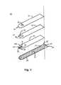
本発明の好ましい実施例を、図1から3に示す。図1は、本発明のセンサ10を示す。センサ10は、積層体100と、流体サンプル抽出端110と、電気接触端120と、通気口52とを備える。流体サンプル抽出端110は、サンプル抽出端口114と通気口52との間にサンプル流体経路112を備える。サンプル端110は、又、インレットノッチ54を有する。電気接触端120は、少なくとも3つのディスクリートな導電接触部122、124、126を備える。All of the advantages of the present invention will become more apparent upon review of the following detailed description, drawings, and accompanying claims.
Detailed Description of the Preferred Embodiments A preferred embodiment of the present invention is shown in FIGS. FIG. 1 shows a
図2では、積層体100が、基部絶縁層20と、第一中間層又は試薬収容層30と、第二中間層又は経路形成層40と、最上層50とから構成されている。全ての層は、誘電性材料、好ましくはプラスチックから作られる。好ましい誘電性材料の例としては、ポリ塩化ビニル、ポリカーボネート、ポリサルフォン、ナイロン、ポリウレタン、硝酸セルロース、プロピオン酸セルロース、酢酸セルロース、酢酸酪酸セルロース、ポリエステル、アクリル、ポリスチレンである。基部絶縁層20は、導電層21を有し、その上に第一導電コンジット22と第二導電コンジット24と第三導電コンジット26とが描かれている。導電コンジット22、24、26は、図2に示すように導電層21にスクライビングまたはスコアリングを行うことにより形成されてもよいし、あるいは、導電コンジット22、24、26を基部層20上にシルクスクリーン捺染することにより形成されてもよい。導電層21のスクライビングまたはスコアリングは、導電層21を機械的に十分にスクライビングすることにより、3つの独立した導電コンジット22、24、26を生成するものであってもよい。本発明の好ましいスクライビングまたはスコアリング法は、炭酸ガス(CO2)レーザか、YAGレーザか、エキシマレーザを用いて行われる。雑音信号を発生させることがある静電気の問題を回避するため、余分なスコアリング線28(説明のためだけに拡大されていて実際の寸法にはなっていない)が基部層20の外縁に沿って設けられていてもよい。なお、スコアリング線28は、センサ10を機能させるのに必要なものではない。導電層21は、どんな導電材料からできていてもよいが、金または酸化スズ/金からなるのが好ましい。基部層20に使用できる材料は、酸化スズ/金ポリエステルフィルム(Cat.No.FM−1)または金ポリエステルフィルム(Cat.No.FM−2)である。これらのフィルムは、カリフォルニア州カノガパークのコートールズパフォーマンスフィルムズ(Courtaulds Performance Films)により販売されている。In FIG. 2, the laminate 100 includes a
第一中間層30は、第一導電コンジット22の一部を露出させる第一電極切取部32と、第二導電コンジット24の一部を露出させる第二電極切取部34と、第三導電コンジット26の一部を露出させる第三電極切取部36とを有する。第一層30は、プラスチック材料から作られ、好ましくは、ペンシルバニア州グレンロックのアドヒーシブリサーチ社(Adhesive Research,Inc.)から購入可能な医療用片面テープから作られる。本発明に適用できるテープの厚さは、およそ0.002−0.005インチ(0.051−0.127mm)である。そのようなテープとしては、Arcare(登録商標)7815が好ましい。なぜなら、扱いやすい上に、十分な量の化学試薬を保持し、センサ10のサンプル流体経路112を通じて好ましい血流速度(毛管現象)を促進する能力において非常に優れたパフォーマンスを示したためである。テープの使用は必ずしも必要ではない。上述のポリエステル製テープを使用するのと同じ結果を得るためには、プラスチックの絶縁層を、粘着剤で覆ってもよいし、また、基部層20に超音波を使って接着してもよいし、あるいは、基部層20上にシルクスクリーン捺染してもよい。 The first
3つの切取部32、34、36は、それぞれ、電極領域W1、R、W2を規定し、2つの作用電極と1つの参照電極とを形成する化学試薬を保持する。通常、電極領域Rには、参照電極を機能させるためにレドックス試薬または媒介物を積めなければならない。Rにレドックス試薬または媒介物が積められていないと、作用電極W1及びW2は適切に機能しない。試薬には、酸化型のレドックス媒介物、安定剤、結合剤、界面活性剤、緩衝剤が含まれるのが好ましい。通常、レドックス媒介物は、フェロセン、フェリシアン化カリウム、その他のフェロセン誘導体のうちの少なくとも1つである。好ましい安定剤は、ポリエチレングリコールであり、好ましい結合剤は、メチルセルロースであり、好ましい界面活性剤は、t−オクチルフェノキシポリエトキシエタノールであり、好ましい緩衝剤は、クエン酸塩緩衝剤である。電極領域W2には、電極領域W1及びRに積められたのと同じ化学試薬が積められるのが好ましいが、さらに酵素及び媒介物が加えられる。酵素は、当該酵素の基質、或いは、酵素に対して触媒としての反応性を有する基質に関わる反応に対して触媒作用を及ぼすことができる。また、媒介物は、酵素触媒反応と作用電極との間で電子を運搬することができ、その結果、酵素または基質の活性及び混合物に対応した電流を生成させる。Rは、W2と同様の化学が積められてもよいことは指摘されるべきである。酵素は、ブドウ糖酸化酵素、乳酸酸化酵素、コレステロールオキシダーゼ、またはクレアチニンアミドヒドロラーゼであってもよい。 The three
第一層30の切取部及び電極領域の位置は、サンプル流体の抵抗が正確に測定され、起こり得る電極領域W2から電極領域W1へのキャリー・オーバーが最小限に抑えられるように、互いに関連して、また、サンプル流体経路112でのサンプル流体の流れに関連して決められる。センサ10の流体サンプル抽出端110を参照点として、電極領域は、W1−W2−R、W1−R−W2、R−W1−W2と配置することができる。好ましい配置は、W1−W2−Rである。 The location of the cutout and electrode area of the
第二中間層40は、第二層センサ端41に位置するU字型の経路切取部42を有している。経路切取部42の長さは、第二中間層40を第一中間層30上に重ねた時、電極領域W1、W2、Rが経路切取部42により規定される空間内に収まる程のものにする。第二中間層40の厚さは、毛管経路の体積及びサンプル流体経路112に流れ込むサンプル流体の速さにとって重要であることがわかった。サンプル流体経路112は、サンプル流体の毛管現象により満たされる。 The second
第二中間層40上に配置される最上層50は、流体経路112内のサンプル流体が完全に電極領域W1、W2、Rを覆うように、センサ10の流体サンプル抽出端110から離れて配置される通気口52を備える。通気口52は、通気口52の少なくとも一部分が、第二中間層40の経路切取部42の底部を露出させるよう最上層50に設けられる。通気口52は、第二中間層40のU字型切取部42の一部を露出させると共に、センサ10の流体サンプル端110から最も遠い第二中間層40のU字型切取部42と部分的に重なるのが好ましい。 The
最上層50は、又、センサ10の流体サンプル端110にインレットノッチ54を有する。インレットノッチ54は、流体経路112におけるサンプルの充填を容易にするために設けられ、サンプルノッチ54がなければ、サンプル端口114は、うっかり塞がれることがある。サンプルノッチ54は、いかなる形状であってもよく、図のように半円形状に限定されない。
試薬1及び2の調合
試薬1及び2は、酸化型のレドックス媒介物、安定剤、結合剤、界面活性剤、緩衝剤を含む。さらに、試薬2は酵素を含む。酸化型のレドックス媒介物であるフェリシアン化カリウムは、マトリクスにおいて安定していることがわかった。製剤に使われる量は、使用可能な直線範囲を得るのに十分でなければならない。酵素はまた、十分な活性、純度、安定性を有していなければならない。市販のグルコースオキシダーゼは、カリフォルニア州サンディエゴのバイオザイム(Biozyme)からCat.No.G03Aとして購入可能であり、およそ270U/mg必要である。安定剤は、水に十分に溶けかつ媒介物と酵素の両方を安定化できなければならない。結合剤もまた、電極領域W1、W2、Rにおける試薬中の他の全ての化学製品を基部層20の導電面/層21に結合できなければならない。好ましい安定剤は、ポリエチレングリコール(Cat.No.P4338、ミズーリ州セントルイスのシグマケミカルズ(Sigma Chemicals))である。好ましい結合剤は、Methocel 60 HG(Cat.No.64655、ウィスコンシン州ミルウォーキーのフルカケミカル(Fluka Chemical))である。緩衝剤溶液は、酵素による反応を最適化するために十分な緩衝力及びpH値を有していなければならない。0.05Mのクエン酸塩緩衝剤が好ましい。界面活性剤は、乾燥した化学試薬を迅速に溶解させると共に、中間層30の切取部32、34、36への試薬1及び2の注入を促進するのに必要である。界面活性剤の量及び種類は、先に記載した機能を確実に果たし、酵素への変性効果を避けるものが選ばれる。好ましい界面活性剤は、Triton X−100である。試薬は以下のように調合される。
試薬1
ステップ1:クエン酸0.1512グラムとクエン酸ナトリウム1.2580グラムとを純水100mlに溶かすことにより、50mMのクエン酸塩緩衝剤を調合する。The
Formulation of Reagents 1 and 2 Reagents 1 and 2 include oxidized redox mediators, stabilizers, binders, surfactants, and buffers. Furthermore, the reagent 2 contains an enzyme. Potassium ferricyanide, an oxidized redox mediator, was found to be stable in the matrix. The amount used in the formulation must be sufficient to obtain a usable linear range. The enzyme must also have sufficient activity, purity and stability. Commercial glucose oxidase is available from Biozyme, San Diego, Calif., Cat. No. It can be purchased as G03A and requires approximately 270 U / mg. The stabilizer must be sufficiently soluble in water and able to stabilize both mediators and enzymes. The binder must also be able to bind all other chemicals in the reagents in the electrode regions W 1, W 2, R to the conductive surface /
Reagent 1
Step 1: Prepare 50 mM citrate buffer by dissolving 0.1512 grams of citric acid and 1.2580 grams of sodium citrate in 100 ml of pure water.
ステップ2:methocel1グラムをステップ1のクエン酸塩緩衝剤100mlに入れて12時間かき混ぜることにより1%のmethocel 60HG溶液を調合する。 Step 2: Prepare 1% method of 60 HG solution by adding 1 gram of method to 100 ml of Step 1 citrate buffer and stirring for 12 hours.
ステップ3:methocel溶液に10%のTriton X−100を0.3ml加える。
ステップ4:ポリエチレングリコール2.5グラムをステップ3の溶液に加える。Step 3: Add 0.3 ml of 10% Triton X-100 to the methocel solution.
Step 4: Add 2.5 grams of polyethylene glycol to Step 3 solution.
ステップ5:かき混ぜながら、フェリシアン化カリウム1グラムをステップ4の溶液に加える。
試薬2
ステップ1−ステップ4:試薬1と同じステップ。Step 5: While stirring, add 1 gram of potassium ferricyanide to the solution from Step 4.
Reagent 2
Step 1-Step 4: Same steps as reagent 1.
ステップ5:かき混ぜながら、フェリシアン化カリウム6.5グラムをステップ4の溶液に加える。
ステップ6:ステップ5の溶液にグルコースオキシダーゼ1.0グラムを加え、10分間あるいは全ての固形物が完全に溶解するまでかき混ぜる。
電極の組み立て
コートールズパフォーマンスフィルムズから購入可能な金または酸化スズ/金ポリエステルフィルムの断片を、図2に示したような、センサ10の基部層20を形成するような形に切断する。金または酸化スズ/金ポリエステルフィルムのスコアリングを行うのにはCO2レーザが使われる。図2に示したように、流体サンプル抽出端110の3つの電極と、3つの接触点122、124、126とが電気接触端120に形成されるように、フィルムにはレーザによりスコアリングがなされた。スコアリング線はとても細いが、3つの別個の導電体を形成するのに十分な太さである。余分なスコアリング線28は、完成したセンサ10から雑音信号生じさせ得る静電気の問題をなくすために基部層20の外縁に沿って入れられるが、必ずしも必要ではない。Step 5: While stirring, add 6.5 grams of potassium ferricyanide to the solution from Step 4.
Step 6: Add 1.0 gram of glucose oxidase to the solution from Step 5 and stir for 10 minutes or until all solids are completely dissolved.
Electrode Assembly A piece of gold or tin oxide / gold polyester film, commercially available from Courtols Performance Films, is cut into a shape that forms the
その後、片面粘着テープの断片を第一中間層30を形成する寸法及び形になるように切断する。その際、テープが、基部層20の導電層21の大部分を覆う一方で、図1に示した小さな電気接触領域を露出させるようにする。ほぼ同じ大きさの3つの長方形、正方形、または、円形の切取部32、34、36をCO2レーザ(カリフォルニア州サンディエゴのシンラッド社(Synrad,Inc.)で購入可能な25Wレーザ)で穴を開けることにより形成する。切取部32、34、36は、化学試薬を入れる電極領域W1、W2、Rを規定する。切取部の寸法は、センサ10の流体サンプル経路112を可能な限り短くするために、可能な限り小さくするのが好ましい。ただし、切取部は、電極が適切に機能するのに十分な量の化学試薬を入れることができるものでなければならない。本発明での好ましい穴の大きさは、0.033インチ(0.84mm)×0.043インチ(1.09mm)程度である。図2に示したように、切取部32、34、36は、0.028インチ(0.71mm)程度の間隔を空けて互いに一直線に並んでいる。切取部が長方形に描かれているのは単に例証的な理由による。切取部の形はたいして重要な問題ではなく、重要なのは、切取部の大きさが電極を十分に機能させるのに十分な量の化学試薬を入れられるほど大きい一方で、サンプル経路を適切に小さくするのに十分なほど小さいということである。前述したように、切取部の形または切取部の表面積を変化させると、式1及び式2の定数k1−k5の変更が必要になり得る。先に延べたように、切取部32、34、36に形成される電極の好ましい配置順は、W1(作用電極1)、W2(作用電極2)、R(参照電極)である。Then, the piece of a single-sided adhesive tape is cut | disconnected so that it may become the dimension and shape which form the 1st intermediate |
0.4マイクロリットルの試薬1を電極領域W1及びRに使用する。試薬1は、レドックス媒介物、安定剤、結合剤、界面活性剤、緩衝剤の混合物である。好ましい試薬1の混合物は、以下の成分を記載の割合で混合することにより生成される:フェリシアン化カリウム約1%、ポリエチレングリコール約2.5%、methocel 60 HG約1%、Triton X−100約0.03%、クエン酸塩緩衝剤(pH5.7)約0.05M。0.4マイクロリットルの試薬2を電極領域W2に使用する。試薬2は、試薬1の混合物に似た混合物であるが、酵素の基質に関わる反応に触媒作用を及ぼすことができる酵素が追加されたものである。好ましい酵素は、グルコースオキシダーゼである。 0.4 microliters of reagent 1 is used for electrode areas W1 and R. Reagent 1 is a mixture of redox mediator, stabilizer, binder, surfactant, and buffer. A preferred reagent 1 mixture is produced by mixing the following ingredients in the stated proportions: about 1% potassium ferricyanide, about 2.5% polyethylene glycol, about 1% methocel 60 HG, about 0 Triton X-100. 0.03%, citrate buffer (pH 5.7) about 0.05M. 0.4 microliters of reagent 2 is used for electrode area W2. Reagent 2 is a mixture similar to that of reagent 1, but with the addition of an enzyme that can catalyze reactions involving the substrate of the enzyme. A preferred enzyme is glucose oxidase.
好ましい試薬2の混合物は、以下の成分を以下の割合で混合することにより生成される:フェリシアン化カリウム約6.5%、ポリエチレングリコール約2.5%、methocel 60HG約1%、Triton X−100約0.03%、クエン酸塩緩衝剤(pH5.7)約0.05M、グルコースオキシダーゼ約1%。試薬を加えた後、装置を55℃のオーブンで約2分間乾燥させた。乾燥後、アドヒーシブリサーチで購入可能な両面テープの断片でU字型経路42を備えた第二中間層40を作成した。そして第二中間層40を第一中間層30の上に重ねる。前述のように、第二中間層40はスペーサの役割を果たし、流体サンプル抽出経路112の大きさを規定する。その幅及び長さは、比較的すばやく動く流体サンプルに合わせて最適化される。U字型経路42の好ましい大きさは、幅0.063インチ(1.60mm)程度、長さ0.248インチ(6.30mm)程度である。 A preferred reagent 2 mixture is produced by mixing the following ingredients in the following proportions: about 6.5% potassium ferricyanide, about 2.5% polyethylene glycol, about 1% methocel 60HG, about Triton X-100. 0.03%, citrate buffer (pH 5.7) approximately 0.05M, glucose oxidase approximately 1%. After the reagent was added, the device was dried in an oven at 55 ° C. for about 2 minutes. After drying, a second
透明フィルム(3Mで購入可能なCat.NO.PP2200またはPP2500)の断片で最上層50を作成する。長方形の通気口52及び半円形のノッチ54を先に記載のCO2レーザを使って形成する。通気口42の好ましい大きさは、0.075インチ(1.91mm)×0.059インチ(1.50mm)程度である。通気口52は、センサ10の流体端110からおよそ0.130インチ(3.3mm)の箇所に位置している。半円形のノッチ54の半径は、約0.030インチ(0.75mm)で、センサ10の流体端110から後退した箇所に位置する。最上層50は、第2中間層40上に位置を調整されて重ねられ、図1に示したセンサ10の組み立てが完成される。The
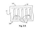
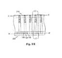
電極の組み立てについての上記の記述は、1つのセンサの組み立てについて記載しているが、その設計及び使用された材料は、図3A−3Eに示したような各層の材料の一片、又は、連続した一片から複数のセンサを製造する場合にも適用できるものである。この製造は、比較的大きな断片である基部層20上に導電層21を載せることから始められる。スコアリングを行うことで複数の線を導電層21に入れるが、その際、図3Aに示したような反復パターンが、前述した好ましいスクライビング法を用いて生成される。これにより、各パターンは、各センサの3つの導電パス22、24、26を最終的に規定する。同様に、図3Bに示されている、反復パターンを示す複数の切取部32、34、36が設けられた第一中間層30の大きな断片は、完成した時に複数のセンサ10が製造されるように基部層20に合う大きさに生成される。各切取部の大きさ及び複数の電極領域W1、R、W2に配置された電極材は、先に開示したものと同様である。各切取部に試薬1及び2を入れて乾燥させた後、複数の細長い切取部42を有する、図3Cに記した第二中間層40の大きな断片を第一中間層30上に重ねる。その際、第二中間層40の各細長い切取部42が第一中間層30の対応する切取部32、34、36を含むようにする。図3Dに示したような反復パターンの複数の通気口52及びノッチ形成口54’を備える同様の大きさの最上層50を第二中間層40の上に重ねる。図3Eは複合層の平面図である。4つの層20、30、40、50によって作成された積層片は、積層片から切り出すことができる複数のセンサ10を有している。積層片を流体サンプル抽出端210で線A−A’に沿
って縦に切ると、サンプルノッチ54を有する複数のサンプル抽出孔114が形成され、電気接触端220で線B−B’に沿って縦に切ると、複数の導電接触部122、124、
126が形成される。また、積層片を所定の間隔を置いて線C−C’に沿って切断すると
、複数の個別のセンサ10が形成される。図1に示したように、各センサ10の流体サンプル抽出端120の成形は好みに応じて実行されてよい。積層片が切り出される順番が重要ではないことは当業者にとっては明らかであろう。例えば、積層片は、所定の間隔(C−C’)で切断されてからA−A’及びB−B’に沿って切断されてもよい。The above description of electrode assembly describes the assembly of one sensor, but the design and material used is a piece of material for each layer as shown in FIGS. 3A-3E, or a continuous The present invention can also be applied to manufacturing a plurality of sensors from one piece. This manufacture begins with the
126 is formed. Further, when the laminated piece is cut along the line CC ′ at a predetermined interval, a plurality of
更なる試験パラメータや実施例とともに本発明を補う特徴のより包括的な記述は、米国特許第6,287,451号に開示されおり、米国特許第6,287,451号は、全て引用によって本願の中に組み込まれている。 A more comprehensive description of features that complement the present invention along with additional test parameters and examples is disclosed in US Pat. No. 6,287,451, which is hereby incorporated by reference in its entirety. It is built in.
本願の好ましい実施例は記述されているが、一例に過ぎない。当業者による本発明の更なる修正は、請求項により規定された本発明の範囲で、施すことができるであろう。 While the preferred embodiment of the present application has been described, it is by way of example only. Further modifications of the invention by those skilled in the art will be possible within the scope of the invention as defined by the claims.
Claims (30)
Translated fromJapanese前記第一の片端と前記通気口の間における、前記少なくとも2つの切取部を含む閉鎖経路と、
前記少なくとも2つの切取部に置かれ、第一の作用電極及び参照電極を形成し、酵素を含有する試薬と、
前記第二の片端にあり、前記閉鎖経路から隔離された導電接触部とを備えた、
使い捨てバイオセンサ。A laminated piece having a first piece end, a second piece end and a vent located at a distance from the first piece end, the base on which at least two electrodes having a conductive coating disposed thereon are depicted above A reagent containing layer having at least two cutouts placed on the base layer, a path forming layer placed on the reagent containing layer, and a coating having a notch at the first one end. A laminated piece provided,
A closed path including the at least two cutouts between the first end and the vent;
A reagent placed in the at least two cutouts to form a first working electrode and a reference electrode, and containing an enzyme;
A conductive contact at the second end and isolated from the closed path;
Disposable biosensor.
6. The stabilizer of claim 5, wherein the stabilizer is polyethylene glycol, the binder is methylcellulose, the surfactant is t-octylphenoxypolyethoxyethanol, and the buffer is a citrate buffer. Biosensor.
第一の基部層端及び第二の基部層端を有する絶縁基部層と、
前記基部層の1つの面に配置される導電層であって、それぞれ絶縁された3つの電気的に異なる導電経路を示す導電層と、
前記絶縁基部層より小さく、前記導電層のかなりの部分を覆う試薬収容層であって、前記試薬収容層は、少なくとも第一切取部と、第一切取部から離れた第二切取部とを有し、第一切取部は、前記少なくとも3つの導電経路のうち第一の限定された部分を露出させ、第二切取部は、前記少なくとも3つの導電経路のうち第二及び第三の限定された部分を露出させる試薬収容層と、
少なくとも2つの電極材料であって、第一の電極材料が、前記少なくとも1つの検体の濃度を測定するための試薬であり、第二の電極材料が、参照材料として使用するのに適した材料であり、前記少なくとも2つの電極材料のそれぞれは、安定剤として少なくともポリアルキレングリコールを含有し、前記第一材料は前記第一切取部に配置され、前記第二材料は前記第二切取部に配置される電極材料と、
前記試薬収容層を覆う大きさであり、該試薬収容層と空間的に同一の広がりを持つ経路形成層であって、前記第一の基部層端から離れた位置にあり、前記試薬収容層の少なくとも2つの切取部を含む前記試薬収容層の一部分を露出させるよう構成された開口を有する経路形成層と、
サンプル流体経路を形成する前記経路形成層を覆う大きさであり、該経路形成層と空間的に同一の広がりを持つ最上層であって、前記第一基部層端と空間的に同一の広がりを持つ第一最上層に、インレットノッチと、前記第一基部層端から離れた位置にあり、前記経路形成層の前記開口の少なくとも小さい部分を露出させるよう構成された最上層通気口とを有する最上層とを備えた電極片。A disposable electrode piece for detecting or measuring the concentration of at least one analyte in a fluid sample,
An insulating base layer having a first base layer end and a second base layer end;
A conductive layer disposed on one surface of the base layer, the conductive layer showing three electrically different conductive paths, each insulated;
A reagent containing layer that is smaller than the insulating base layer and covers a substantial portion of the conductive layer, the reagent containing layer comprising at least a first take-off portion and a second cut-out portion separated from the first take-up portion; The first take-off portion exposes the first limited portion of the at least three conductive paths, and the second cut-out portion has the second and third of the at least three conductive paths. A reagent containing layer that exposes a limited portion;
At least two electrode materials, wherein the first electrode material is a reagent for measuring the concentration of the at least one analyte, and the second electrode material is a material suitable for use as a reference material. Each of the at least two electrode materials contains at least polyalkylene glycol as a stabilizer, the first material is disposed in the first cut portion, and the second material is disposed in the second cut portion. An electrode material,
A path-forming layer having a size that covers the reagent-containing layer and having the same spatial extent as the reagent-containing layer, being located away from the end of the first base layer, A path-forming layer having an opening configured to expose a portion of the reagent-containing layer including at least two cut-out portions;
A top layer that is spatially coextensive with the path forming layer and that is spatially coextensive with the end of the first base layer. A first top layer having an inlet notch and a top layer vent located at a distance from the end of the first base layer and configured to expose at least a small portion of the opening of the path forming layer. An electrode piece comprising an upper layer.
The apparatus of claim 18, wherein the first material and the second material comprise a redox mediator, a binder, a surfactant, and a buffer.
電極端と、基部層の長さに沿って少なくとも2つの細長い導電性コンジットを形成する電気接触端とを備えた細長い基部層の1つの面に配置された導電性被膜をスクライブし、前記少なくとも2つの導電性コンジットのうち第一コンジットはL字型で、前記第一コンジットのL字型部分は第二コンジットに近接し、前記第一コンジットのL字型端部及び前記第二コンジットの一部分は、前記電極端の近くに位置していることと、
前記基部層より短い試薬収容層を前記基部層上に付着させ、少なくとも2つの細長いコンジットのそれぞれの部分は、前記電気接触端で露出され、前記試薬収容層は、前記電極端から離れた少なくとも2つの試薬収容切取部を有し、第一の切取部は、前記第一コンジットの一部分を露出させ、第二コンジットは、前記第二コンジットの一部分を露出させることと、
参照電極を形成する前記第一切取部及び第一の作用電極を形成する第二切取部に、混合試薬を加え、少なくとも前記第一の作用電極中の前記混合試薬は、酵素の基質に関わる反応に対して触媒作用を及ぼすことができる酵素を含有することと、
試薬マトリクスを形成する前記混合試薬を乾燥させることと、
前記試薬収容層上に経路形成層を配置し、前記経路形成層は、前記試薬収容層の前記少なくとも2つの試薬切取部を露出させる大きさに中央の細長い経路を規定するU字型端部分を有することと、
前記経路形成層上に最上層を配置し、該最上層は、前記電極端から離れた位置に通気口及び前記電極端にノッチを有し、かつ、前記U字型端部分に注入口及び毛管空間を形成し、前記通気口は、前記注入口の反対側の前記毛管空間の端に前記中央経路の一部分を露出させ、前記ノッチは、前記注入口に前記中央経路の一部分を露出させることと、を含む方法。A method for manufacturing a disposable biosensor,
Scribing a conductive coating disposed on one surface of the elongate base layer with an electrode end and an electrical contact end forming at least two elongate conductive conduits along the length of the base layer; Of the two conductive conduits, the first conduit is L-shaped, the L-shaped portion of the first conduit is adjacent to the second conduit, and the L-shaped end of the first conduit and a portion of the second conduit are Being located near the end of the electrode;
A reagent containing layer shorter than the base layer is deposited on the base layer, each portion of at least two elongated conduits is exposed at the electrical contact end, and the reagent containing layer is at least 2 away from the electrode end. Two reagent containing cutouts, the first cutout exposing a portion of the first conduit and the second conduit exposing a portion of the second conduit;
A mixed reagent is added to the first take-out part forming the reference electrode and the second cut-out part forming the first working electrode, and at least the mixed reagent in the first working electrode is related to the enzyme substrate. Containing an enzyme capable of catalyzing the reaction;
Drying the mixed reagents forming a reagent matrix;
A path-forming layer is disposed on the reagent-containing layer, and the path-forming layer has a U-shaped end portion defining a central elongate path to a size that exposes the at least two reagent cut-out portions of the reagent-containing layer. Having
An uppermost layer is disposed on the path forming layer, and the uppermost layer has a vent at a position away from the electrode end and a notch at the electrode end, and an inlet and a capillary at the U-shaped end portion. Forming a space, wherein the vent exposes a portion of the central path to the end of the capillary space opposite the inlet, and the notch exposes a portion of the central path to the inlet; , Including methods.
導電材料の層が上に載せられている、第一端及び第二端を有する絶縁材料の基部層片を用意することと、
前記導電材料に反復パターンで複数の線をスクライビングにより形成し、該複数の線は該反復パターンのそれぞれの内に3つの導電経路を形成する反復パターンを含むことと、
前記基部層片上に絶縁材料から成る第一の中間層を配置し、該第一の中間層は、少なくとも2つの切取部の反復パターンを有し、該反復パターンのそれぞれの各切取部は、前記導電性層の少なくとも電極の一部分を露出させ、前記少なくとも2つの切取部の反復パターンは、前記基部層片の前記第一端から離れた位置にあり、前記第一の中間層は、前記基部層片の前記第二端と距離を置いて、各反復パターンの前記3つの導電経路のそれぞれの接触部を露出させる大きさにすることと、
各反復パターンの前記少なくとも2つの切取部のうち一方に第一の試薬材料を置き、各反復パターンの前記少なくとも2つの切取部のうち他方に、第二の試薬材料を置くことと、
前記第一の試薬材料及び前記第二の試薬材料を乾燥させることと、
前記第一の中間層を覆い、前記第一の中間層と空間的に同一の広がりを持つ第二の中間層を前記第一の中間層に載せ、該第二の中間層は、反復パターンの複数の細長い切取部を有し、該細長い切取部のそれぞれは、前記第一の中間層の前記少なくとも2つの切取部の対応する反復パターンを露出させることと、
前記第二の中間層を覆い、前記第二の中間層と空間的に同一の広がりを持つ絶縁材料の最上層を配置し、該最上層は反復パターンの複数の通気口及びノッチ形成穴を有し、該通気口のそれぞれは、前記細長い切取部の前記基部層片の前記第一端から最も離れた部分に対応する反復パターンの一部分を露出させ、前記ノッチ形成穴のそれぞれは、前記細長い切取部の前記基部層片の前記第一端から最も近い部分に対応する反復パターンの一部分を露出させ、前記基部層片、前記第一の中間層、前記第二の中間層、及び前記最上層が積層片を形成することと、
前記積層片の前記第一端に沿って、該第一端と平行に所定の距離を切り取って、前記反復パターンのそれぞれに対する前記最上層の前記細長い切取部及びインレットノッチのそれぞれにサンプル注入口を形成することと、
前記積層片の前記第二端に沿って、該第二端と平行に所定の距離を切り取って、前記反復パターンのそれぞれについて3つの別個の接触部を形成することと、
前記使い捨てセンサの一つ一つを形成する前記反復パターンのそれぞれを分離することと、を含む方法。Each sensor has at least a first working electrode and a reference electrode, the first working electrode containing an enzyme capable of catalyzing a reaction involving a substrate of the enzyme, and at least a first working electrode A method of manufacturing a plurality of disposable sensors, wherein the electrode and the reference electrode are disposed in a fluid sample path for measuring a fluid sample, comprising:
Providing a base layer piece of insulating material having a first end and a second end, overlaid with a layer of conductive material;
Scribing a plurality of lines in the conductive material in a repeating pattern, the plurality of lines including a repeating pattern forming three conductive paths within each of the repeating patterns;
A first intermediate layer of insulating material is disposed on the base layer piece, the first intermediate layer having a repeating pattern of at least two cutouts, each cutout of each of the repeating patterns being Exposing at least a portion of the electrode of the conductive layer, wherein the repeating pattern of the at least two cutouts is located away from the first end of the base layer piece, and the first intermediate layer is the base layer Sized to expose the respective contacts of the three conductive paths of each repeating pattern at a distance from the second end of the strip;
Placing a first reagent material in one of the at least two cutouts of each repeating pattern and placing a second reagent material in the other of the at least two cutouts of each repeating pattern;
Drying the first reagent material and the second reagent material;
A second intermediate layer covering the first intermediate layer and spatially coextensive with the first intermediate layer is placed on the first intermediate layer, and the second intermediate layer has a repetitive pattern. A plurality of elongated cuts, each of the elongated cuts exposing a corresponding repeating pattern of the at least two cuts of the first intermediate layer;
Covering the second intermediate layer and placing a top layer of insulating material that is spatially coextensive with the second intermediate layer, the top layer having a plurality of repetitive patterns of vents and notch formation holes. And each of the vents exposes a portion of a repetitive pattern corresponding to a portion of the base cutout that is farthest from the first end of the base layer piece, and each of the notch forming holes is formed of the thinned cutout. Exposing a portion of the repetitive pattern corresponding to the portion of the base layer piece closest to the first end of the portion, wherein the base layer piece, the first intermediate layer, the second intermediate layer, and the top layer are Forming laminated pieces;
A predetermined distance is cut along the first end of the laminated piece in parallel with the first end, and a sample inlet is provided in each of the elongated cutout and the inlet notch in the uppermost layer for each of the repetitive patterns. Forming,
Cutting a predetermined distance along the second end of the laminate piece in parallel with the second end to form three separate contacts for each of the repeating patterns;
Separating each of the repeating patterns forming each of the disposable sensors.
Applications Claiming Priority (2)
| Application Number | Priority Date | Filing Date | Title |
|---|---|---|---|
| US10/126,819US6837976B2 (en) | 2002-04-19 | 2002-04-19 | Disposable sensor with enhanced sample port inlet |
| PCT/US2003/011554WO2003089658A1 (en) | 2002-04-19 | 2003-04-16 | Disposable sensor with enhanced sample port inlet |
Publications (2)
| Publication Number | Publication Date |
|---|---|
| JP2005523443Atrue JP2005523443A (en) | 2005-08-04 |
| JP4620356B2 JP4620356B2 (en) | 2011-01-26 |
Family
ID=29248425
Family Applications (1)
| Application Number | Title | Priority Date | Filing Date |
|---|---|---|---|
| JP2003586367AExpired - LifetimeJP4620356B2 (en) | 2002-04-19 | 2003-04-16 | Disposable sensor with improved sample inlet |
Country Status (8)
| Country | Link |
|---|---|
| US (1) | US6837976B2 (en) |
| EP (1) | EP1497449B1 (en) |
| JP (1) | JP4620356B2 (en) |
| AU (1) | AU2003228535A1 (en) |
| CA (1) | CA2481425C (en) |
| DE (1) | DE60319973T2 (en) |
| ES (1) | ES2302927T3 (en) |
| WO (1) | WO2003089658A1 (en) |
Cited By (8)
| Publication number | Priority date | Publication date | Assignee | Title |
|---|---|---|---|---|
| JP2007003361A (en)* | 2005-06-24 | 2007-01-11 | Matsushita Electric Ind Co Ltd | Biosensor |
| WO2008072702A1 (en)* | 2006-12-14 | 2008-06-19 | Nippon Kayaku Kabushiki Kaisha | Method for measuring 1,5-anhydroglucitol in whole blood, and sensor chip and measurement kit to be used in the method |
| JP2013061336A (en)* | 2011-09-12 | 2013-04-04 | Nova Biomedical Corp | Disposable sensor for electrochemical detection of hemoglobin |
| US8753832B2 (en) | 2005-06-13 | 2014-06-17 | Nippon Kayaku Kabushiki Kaisha | Method of assaying 1,5 anhydroglucitol by using whole blood and measurement kit |
| JP2015092194A (en)* | 2008-01-17 | 2015-05-14 | ライフスキャン・インコーポレイテッドLifescan,Inc. | Method of identifying defects in test pieces |
| JP2016514830A (en)* | 2013-03-19 | 2016-05-23 | エフ.ホフマン−ラ ロシュ アーゲーF. Hoffmann−La Roche Aktiengesellschaft | Method / apparatus for generating a correction value for an analyte concentration in a body fluid sample |
| WO2024074913A1 (en)* | 2022-10-06 | 2024-04-11 | Solventum Intellectual Properties Company | Test device, sterilization monitoring system and method |
| WO2024074912A3 (en)* | 2022-10-06 | 2024-07-11 | Solventum Intellectual Properties Company | Test device, sterilization monitoring system and method |
Families Citing this family (107)
| Publication number | Priority date | Publication date | Assignee | Title |
|---|---|---|---|---|
| US6036924A (en) | 1997-12-04 | 2000-03-14 | Hewlett-Packard Company | Cassette of lancet cartridges for sampling blood |
| US6391005B1 (en) | 1998-03-30 | 2002-05-21 | Agilent Technologies, Inc. | Apparatus and method for penetration with shaft having a sensor for sensing penetration depth |
| DE10057832C1 (en)* | 2000-11-21 | 2002-02-21 | Hartmann Paul Ag | Blood analysis device has syringe mounted in casing, annular mounting carrying needles mounted behind test strip and being swiveled so that needle can be pushed through strip and aperture in casing to take blood sample |
| US8641644B2 (en) | 2000-11-21 | 2014-02-04 | Sanofi-Aventis Deutschland Gmbh | Blood testing apparatus having a rotatable cartridge with multiple lancing elements and testing means |
| JP4209767B2 (en) | 2001-06-12 | 2009-01-14 | ペリカン テクノロジーズ インコーポレイテッド | Self-optimized cutting instrument with adaptive means for temporary changes in skin properties |
| US7981056B2 (en) | 2002-04-19 | 2011-07-19 | Pelikan Technologies, Inc. | Methods and apparatus for lancet actuation |
| WO2002101359A2 (en) | 2001-06-12 | 2002-12-19 | Pelikan Technologies, Inc. | Integrated blood sampling analysis system with multi-use sampling module |
| US7749174B2 (en) | 2001-06-12 | 2010-07-06 | Pelikan Technologies, Inc. | Method and apparatus for lancet launching device intergrated onto a blood-sampling cartridge |
| US9427532B2 (en) | 2001-06-12 | 2016-08-30 | Sanofi-Aventis Deutschland Gmbh | Tissue penetration device |
| JP4272051B2 (en) | 2001-06-12 | 2009-06-03 | ペリカン テクノロジーズ インコーポレイテッド | Blood sampling apparatus and method |
| US20070100255A1 (en)* | 2002-04-19 | 2007-05-03 | Pelikan Technologies, Inc. | Method and apparatus for body fluid sampling and analyte sensing |
| AU2002344825A1 (en) | 2001-06-12 | 2002-12-23 | Pelikan Technologies, Inc. | Method and apparatus for improving success rate of blood yield from a fingerstick |
| EP1395185B1 (en) | 2001-06-12 | 2010-10-27 | Pelikan Technologies Inc. | Electric lancet actuator |
| US8337419B2 (en) | 2002-04-19 | 2012-12-25 | Sanofi-Aventis Deutschland Gmbh | Tissue penetration device |
| US7041068B2 (en) | 2001-06-12 | 2006-05-09 | Pelikan Technologies, Inc. | Sampling module device and method |
| US7344507B2 (en) | 2002-04-19 | 2008-03-18 | Pelikan Technologies, Inc. | Method and apparatus for lancet actuation |
| US9795747B2 (en) | 2010-06-02 | 2017-10-24 | Sanofi-Aventis Deutschland Gmbh | Methods and apparatus for lancet actuation |
| US9226699B2 (en) | 2002-04-19 | 2016-01-05 | Sanofi-Aventis Deutschland Gmbh | Body fluid sampling module with a continuous compression tissue interface surface |
| US7344894B2 (en) | 2001-10-16 | 2008-03-18 | Agilent Technologies, Inc. | Thermal regulation of fluidic samples within a diagnostic cartridge |
| US8267870B2 (en) | 2002-04-19 | 2012-09-18 | Sanofi-Aventis Deutschland Gmbh | Method and apparatus for body fluid sampling with hybrid actuation |
| US8579831B2 (en) | 2002-04-19 | 2013-11-12 | Sanofi-Aventis Deutschland Gmbh | Method and apparatus for penetrating tissue |
| US7291117B2 (en) | 2002-04-19 | 2007-11-06 | Pelikan Technologies, Inc. | Method and apparatus for penetrating tissue |
| US7244265B2 (en) | 2002-04-19 | 2007-07-17 | Pelikan Technologies, Inc. | Method and apparatus for penetrating tissue |
| US7331931B2 (en) | 2002-04-19 | 2008-02-19 | Pelikan Technologies, Inc. | Method and apparatus for penetrating tissue |
| US8702624B2 (en) | 2006-09-29 | 2014-04-22 | Sanofi-Aventis Deutschland Gmbh | Analyte measurement device with a single shot actuator |
| US7648468B2 (en) | 2002-04-19 | 2010-01-19 | Pelikon Technologies, Inc. | Method and apparatus for penetrating tissue |
| US7674232B2 (en) | 2002-04-19 | 2010-03-09 | Pelikan Technologies, Inc. | Method and apparatus for penetrating tissue |
| US9248267B2 (en) | 2002-04-19 | 2016-02-02 | Sanofi-Aventis Deustchland Gmbh | Tissue penetration device |
| US7491178B2 (en) | 2002-04-19 | 2009-02-17 | Pelikan Technologies, Inc. | Method and apparatus for penetrating tissue |
| US7909778B2 (en) | 2002-04-19 | 2011-03-22 | Pelikan Technologies, Inc. | Method and apparatus for penetrating tissue |
| WO2003088824A2 (en) | 2002-04-19 | 2003-10-30 | Pelikan Technologies, Inc. | Device and method for variable speed lancet |
| US7708701B2 (en) | 2002-04-19 | 2010-05-04 | Pelikan Technologies, Inc. | Method and apparatus for a multi-use body fluid sampling device |
| US7901362B2 (en) | 2002-04-19 | 2011-03-08 | Pelikan Technologies, Inc. | Method and apparatus for penetrating tissue |
| US7232451B2 (en) | 2002-04-19 | 2007-06-19 | Pelikan Technologies, Inc. | Method and apparatus for penetrating tissue |
| US7582099B2 (en) | 2002-04-19 | 2009-09-01 | Pelikan Technologies, Inc | Method and apparatus for penetrating tissue |
| US7374544B2 (en) | 2002-04-19 | 2008-05-20 | Pelikan Technologies, Inc. | Method and apparatus for penetrating tissue |
| US7485128B2 (en) | 2002-04-19 | 2009-02-03 | Pelikan Technologies, Inc. | Method and apparatus for penetrating tissue |
| US7371247B2 (en) | 2002-04-19 | 2008-05-13 | Pelikan Technologies, Inc | Method and apparatus for penetrating tissue |
| US7892183B2 (en) | 2002-04-19 | 2011-02-22 | Pelikan Technologies, Inc. | Method and apparatus for body fluid sampling and analyte sensing |
| US7524293B2 (en) | 2002-04-19 | 2009-04-28 | Pelikan Technologies, Inc. | Method and apparatus for penetrating tissue |
| US7563232B2 (en) | 2002-04-19 | 2009-07-21 | Pelikan Technologies, Inc. | Method and apparatus for penetrating tissue |
| US9795334B2 (en) | 2002-04-19 | 2017-10-24 | Sanofi-Aventis Deutschland Gmbh | Method and apparatus for penetrating tissue |
| US7547287B2 (en) | 2002-04-19 | 2009-06-16 | Pelikan Technologies, Inc. | Method and apparatus for penetrating tissue |
| US7976476B2 (en) | 2002-04-19 | 2011-07-12 | Pelikan Technologies, Inc. | Device and method for variable speed lancet |
| US7717863B2 (en) | 2002-04-19 | 2010-05-18 | Pelikan Technologies, Inc. | Method and apparatus for penetrating tissue |
| US7410468B2 (en) | 2002-04-19 | 2008-08-12 | Pelikan Technologies, Inc. | Method and apparatus for penetrating tissue |
| US7141058B2 (en) | 2002-04-19 | 2006-11-28 | Pelikan Technologies, Inc. | Method and apparatus for a body fluid sampling device using illumination |
| US7229458B2 (en) | 2002-04-19 | 2007-06-12 | Pelikan Technologies, Inc. | Method and apparatus for penetrating tissue |
| US8784335B2 (en) | 2002-04-19 | 2014-07-22 | Sanofi-Aventis Deutschland Gmbh | Body fluid sampling device with a capacitive sensor |
| US8372016B2 (en) | 2002-04-19 | 2013-02-12 | Sanofi-Aventis Deutschland Gmbh | Method and apparatus for body fluid sampling and analyte sensing |
| US8221334B2 (en) | 2002-04-19 | 2012-07-17 | Sanofi-Aventis Deutschland Gmbh | Method and apparatus for penetrating tissue |
| US9314194B2 (en) | 2002-04-19 | 2016-04-19 | Sanofi-Aventis Deutschland Gmbh | Tissue penetration device |
| US8360992B2 (en) | 2002-04-19 | 2013-01-29 | Sanofi-Aventis Deutschland Gmbh | Method and apparatus for penetrating tissue |
| US7297122B2 (en) | 2002-04-19 | 2007-11-20 | Pelikan Technologies, Inc. | Method and apparatus for penetrating tissue |
| US20040087034A1 (en)* | 2002-10-30 | 2004-05-06 | Ching Ho Lien | Test strip |
| US20080044927A1 (en)* | 2002-10-30 | 2008-02-21 | Lien Ching H | Medical test strip |
| US7265881B2 (en)* | 2002-12-20 | 2007-09-04 | Hewlett-Packard Development Company, L.P. | Method and apparatus for measuring assembly and alignment errors in sensor assemblies |
| US8574895B2 (en) | 2002-12-30 | 2013-11-05 | Sanofi-Aventis Deutschland Gmbh | Method and apparatus using optical techniques to measure analyte levels |
| US7144485B2 (en)* | 2003-01-13 | 2006-12-05 | Hmd Biomedical Inc. | Strips for analyzing samples |
| DE602004028463D1 (en) | 2003-05-30 | 2010-09-16 | Pelikan Technologies Inc | METHOD AND DEVICE FOR INJECTING LIQUID |
| US7850621B2 (en) | 2003-06-06 | 2010-12-14 | Pelikan Technologies, Inc. | Method and apparatus for body fluid sampling and analyte sensing |
| WO2006001797A1 (en) | 2004-06-14 | 2006-01-05 | Pelikan Technologies, Inc. | Low pain penetrating |
| EP1635700B1 (en) | 2003-06-13 | 2016-03-09 | Sanofi-Aventis Deutschland GmbH | Apparatus for a point of care device |
| JP4447009B2 (en)* | 2003-06-20 | 2010-04-07 | エフ ホフマン−ラ ロッシュ アクチェン ゲゼルシャフト | Test strip with slot vent opening |
| US8282576B2 (en) | 2003-09-29 | 2012-10-09 | Sanofi-Aventis Deutschland Gmbh | Method and apparatus for an improved sample capture device |
| EP1680014A4 (en) | 2003-10-14 | 2009-01-21 | Pelikan Technologies Inc | METHOD AND DEVICE FOR A VARIABLE USER INTERFACE |
| DE602004021835D1 (en)* | 2003-10-31 | 2009-08-13 | Lifescan Scotland Ltd | METHOD FOR REDUCING INTERFERENCE IN AN ELECTROCHEMICAL SENSOR USING TWO DIFFERENT APPROPRIATE POTENTIALS |
| EP1707953B1 (en) | 2003-12-04 | 2015-07-01 | Panasonic Healthcare Holdings Co., Ltd. | Method of measuring hematocrit (Hct) |
| CN100472210C (en) | 2003-12-04 | 2009-03-25 | 松下电器产业株式会社 | Method for measuring blood components and sensor and measuring device used in the method |
| US8668656B2 (en) | 2003-12-31 | 2014-03-11 | Sanofi-Aventis Deutschland Gmbh | Method and apparatus for improving fluidic flow and sample capture |
| US7822454B1 (en) | 2005-01-03 | 2010-10-26 | Pelikan Technologies, Inc. | Fluid sampling device with improved analyte detecting member configuration |
| EP3115777B1 (en)* | 2004-04-19 | 2020-01-08 | PHC Holdings Corporation | Method for measuring blood components |
| WO2006011062A2 (en) | 2004-05-20 | 2006-02-02 | Albatros Technologies Gmbh & Co. Kg | Printable hydrogel for biosensors |
| US7118667B2 (en)* | 2004-06-02 | 2006-10-10 | Jin Po Lee | Biosensors having improved sample application and uses thereof |
| WO2005120365A1 (en) | 2004-06-03 | 2005-12-22 | Pelikan Technologies, Inc. | Method and apparatus for a fluid sampling device |
| US9775553B2 (en) | 2004-06-03 | 2017-10-03 | Sanofi-Aventis Deutschland Gmbh | Method and apparatus for a fluid sampling device |
| US8652831B2 (en) | 2004-12-30 | 2014-02-18 | Sanofi-Aventis Deutschland Gmbh | Method and apparatus for analyte measurement test time |
| US7611621B2 (en)* | 2005-06-13 | 2009-11-03 | Nova Biomedical Corporation | Disposable oxygen sensor and method for correcting oxygen effect on oxidase-based analytical devices |
| US8617366B2 (en)* | 2005-12-12 | 2013-12-31 | Nova Biomedical Corporation | Disposable urea sensor and system for determining creatinine and urea nitrogen-to-creatinine ratio in a single device |
| US20080006530A1 (en)* | 2006-06-19 | 2008-01-10 | Handani Winarta | Capillary Flow Control in a Flow Channel |
| WO2008040998A2 (en)* | 2006-10-05 | 2008-04-10 | Lifescan Scotland Limited | Systems and methods for determining a substantially hematocrit independent analyte concentration |
| US9046480B2 (en) | 2006-10-05 | 2015-06-02 | Lifescan Scotland Limited | Method for determining hematocrit corrected analyte concentrations |
| US7802467B2 (en) | 2006-12-22 | 2010-09-28 | Abbott Diabetes Care Inc. | Analyte sensors and methods of use |
| USD587142S1 (en) | 2006-12-22 | 2009-02-24 | Abbott Diabetes Care Inc. | Sensors |
| US8299317B2 (en)* | 2007-03-29 | 2012-10-30 | Kimberly-Clark Worldwide, Inc. | Absorbent articles with external access to internal conductors |
| TW200914826A (en)* | 2007-09-21 | 2009-04-01 | Apex Biotechnology Corp | Electrochemical quantitative analysis system and method for the same |
| KR100890988B1 (en)* | 2007-10-29 | 2009-03-31 | 주식회사 아이센스 | Electrochemical biosensor equipped with sample introduction part that can uniformly introduce small amount of sample |
| EP2265324B1 (en) | 2008-04-11 | 2015-01-28 | Sanofi-Aventis Deutschland GmbH | Integrated analyte measurement system |
| US20100187132A1 (en)* | 2008-12-29 | 2010-07-29 | Don Alden | Determination of the real electrochemical surface areas of screen printed electrodes |
| US9375169B2 (en) | 2009-01-30 | 2016-06-28 | Sanofi-Aventis Deutschland Gmbh | Cam drive for managing disposable penetrating member actions with a single motor and motor and control system |
| KR100918027B1 (en)* | 2009-02-19 | 2009-09-18 | 주식회사 올메디쿠스 | Biosensor with code electrode, manufacturing method thereof, and sensor information acquisition method thereof |
| US8500990B2 (en)* | 2009-04-22 | 2013-08-06 | Nova Biomedical Corporation | Electrochemical biosensors based on NAD(P)-dependent dehydrogenase enzymes |
| US8965476B2 (en) | 2010-04-16 | 2015-02-24 | Sanofi-Aventis Deutschland Gmbh | Tissue penetration device |
| JP2013530409A (en)* | 2010-07-14 | 2013-07-25 | 紅電醫學科技股▲分▼有限公司 | Test strip for body fluid sample detection |
| US20130084590A1 (en)* | 2011-09-30 | 2013-04-04 | Lifescan Scotland Ltd. | Analytical test strip with bodily fluid phase-shift measurement electrodes |
| US20130098775A1 (en)* | 2011-10-20 | 2013-04-25 | Nova Biomedical Corporation | Glucose biosensor with improved shelf life |
| KR101466222B1 (en)* | 2012-06-01 | 2014-12-01 | 주식회사 아이센스 | Electrochemical biosensor with improved accuracy |
| TW201415015A (en)* | 2012-10-15 | 2014-04-16 | Ichia Tech Inc | Method for manufacturing test plate for biologic liquid and structure for the same |
| CN103091377B (en)* | 2013-02-05 | 2015-01-21 | 三诺生物传感股份有限公司 | Biosensor |
| US10898116B2 (en)* | 2013-03-15 | 2021-01-26 | Cambridge Medical Technologies LLC | Methods of manufacture to optimize performance of transdermal sampling and analysis device |
| CN104062319A (en)* | 2013-03-22 | 2014-09-24 | 毅嘉科技股份有限公司 | Biological fluid test piece manufacturing method and its structure |
| CN104007150A (en)* | 2013-12-04 | 2014-08-27 | 西南大学 | Conductive polymer-based all-print biological and environmental sensor and making method thereof |
| CN104450864A (en)* | 2014-12-18 | 2015-03-25 | 三诺生物传感股份有限公司 | Composition and application thereof |
| US9891209B2 (en)* | 2015-05-29 | 2018-02-13 | C A Casyso Gmbh | Electrode assembly for measurement of platelet function in whole blood |
| US10802071B2 (en)* | 2017-12-01 | 2020-10-13 | International Business Machines Corporation | Elemental mercury-containing probe card |
| US11633129B2 (en) | 2019-04-05 | 2023-04-25 | Cambridge Medical Technologies LLC | Non-invasive transdermal sampling and analysis device incorporating redox cofactors |
| US11375931B2 (en) | 2019-08-08 | 2022-07-05 | Cambridge Medical Technologies LLC | Non-invasive transdermal sampling and analysis device incorporating an electrochemical bioassay |
Citations (4)
| Publication number | Priority date | Publication date | Assignee | Title |
|---|---|---|---|---|
| JP2000500572A (en)* | 1995-11-16 | 2000-01-18 | メムテック・アメリカ・コーポレイション | Electrochemical cell |
| WO2000073785A2 (en)* | 1999-06-02 | 2000-12-07 | Nova Biomedical Corporation | Low interference disposable sensor and method of making |
| JP2001526388A (en)* | 1997-12-05 | 2001-12-18 | ロシュ ダイアグノスティックス コーポレーション | Improved electrochemical biosensor test strip |
| EP1195441A1 (en)* | 2000-10-06 | 2002-04-10 | Roche Diagnostics GmbH | Biosensor |
Family Cites Families (56)
| Publication number | Priority date | Publication date | Assignee | Title |
|---|---|---|---|---|
| CH559912A5 (en)* | 1971-09-09 | 1975-03-14 | Hoffmann La Roche | |
| US3979274A (en)* | 1975-09-24 | 1976-09-07 | The Yellow Springs Instrument Company, Inc. | Membrane for enzyme electrodes |
| US4137495A (en)* | 1976-03-27 | 1979-01-30 | Brown David M B | Oil detector |
| US4053381A (en)* | 1976-05-19 | 1977-10-11 | Eastman Kodak Company | Device for determining ionic activity of components of liquid drops |
| FR2387659A1 (en)* | 1977-04-21 | 1978-11-17 | Armines | GLYCEMIA CONTROL AND REGULATION DEVICE |
| US4133735A (en)* | 1977-09-27 | 1979-01-09 | The Board Of Regents Of The University Of Washington | Ion-sensitive electrode and processes for making the same |
| JPS5912135B2 (en)* | 1977-09-28 | 1984-03-21 | 松下電器産業株式会社 | enzyme electrode |
| US4321123A (en)* | 1978-04-21 | 1982-03-23 | Matsushita Electric Industrial Co., Ltd. | Coenzyme immobilized electrode |
| US4185131A (en)* | 1978-06-28 | 1980-01-22 | United Technologies Corporation | Screen printing method for making an electrochemical cell electrode |
| US4184936A (en)* | 1978-07-24 | 1980-01-22 | Eastman Kodak Company | Device for determining ionic activity |
| US4233029A (en)* | 1978-10-25 | 1980-11-11 | Eastman Kodak Company | Liquid transport device and method |
| US4225410A (en)* | 1978-12-04 | 1980-09-30 | Technicon Instruments Corporation | Integrated array of electrochemical sensors |
| US4273639A (en)* | 1979-06-20 | 1981-06-16 | Eastman Kodak Company | Capillary bridge in apparatus for determining ionic activity |
| US4310399A (en)* | 1979-07-23 | 1982-01-12 | Eastman Kodak Company | Liquid transport device containing means for delaying capillary flow |
| US4301414A (en)* | 1979-10-29 | 1981-11-17 | United States Surgical Corporation | Disposable sample card and method of making same |
| US4303887A (en)* | 1979-10-29 | 1981-12-01 | United States Surgical Corporation | Electrical liquid conductivity measuring system |
| US4413407A (en)* | 1980-03-10 | 1983-11-08 | Eastman Kodak Company | Method for forming an electrode-containing device with capillary transport between electrodes |
| US4356074A (en)* | 1980-08-25 | 1982-10-26 | The Yellow Springs Instrument Company, Inc. | Substrate specific galactose oxidase enzyme electrodes |
| GB2096825A (en)* | 1981-04-09 | 1982-10-20 | Sibbald Alastair | Chemical sensitive semiconductor field effect transducer |
| FR2508305B1 (en)* | 1981-06-25 | 1986-04-11 | Slama Gerard | DEVICE FOR CAUSING A LITTLE BITE TO COLLECT A BLOOD DROP |
| EP0078636B2 (en)* | 1981-10-23 | 1997-04-02 | MediSense, Inc. | Sensor for components of a liquid mixture |
| US4418148A (en)* | 1981-11-05 | 1983-11-29 | Miles Laboratories, Inc. | Multilayer enzyme electrode membrane |
| US4473457A (en)* | 1982-03-29 | 1984-09-25 | Eastman Kodak Company | Liquid transport device providing diversion of capillary flow into a non-vented second zone |
| EP0096095B1 (en) | 1982-06-14 | 1988-11-09 | Corporation Ohmicron | Semiconductor device, sensor and method for determining the concentration of an analyte in a medium |
| US4454007A (en)* | 1983-01-27 | 1984-06-12 | E. I. Du Pont De Nemours And Company | Ion-selective layered sensor and methods of making and using the same |
| US4490216A (en)* | 1983-02-03 | 1984-12-25 | Molecular Devices Corporation | Lipid membrane electroanalytical elements and method of analysis therewith |
| WO1984003562A1 (en) | 1983-03-11 | 1984-09-13 | Matsushita Electric Industrial Co Ltd | Biosensor |
| GB8308389D0 (en) | 1983-03-26 | 1983-05-05 | Cambridge Life Sciences | Assay technique |
| US5682884A (en)* | 1983-05-05 | 1997-11-04 | Medisense, Inc. | Strip electrode with screen printing |
| US5509410A (en)* | 1983-06-06 | 1996-04-23 | Medisense, Inc. | Strip electrode including screen printing of a single layer |
| US4591550A (en)* | 1984-03-01 | 1986-05-27 | Molecular Devices Corporation | Device having photoresponsive electrode for determining analytes including ligands and antibodies |
| US4654127A (en)* | 1984-04-11 | 1987-03-31 | Sentech Medical Corporation | Self-calibrating single-use sensing device for clinical chemistry and method of use |
| EP0170375B1 (en) | 1984-06-13 | 1990-05-16 | Unilever Plc | Devices for use in chemical test procedures |
| US5141868A (en)* | 1984-06-13 | 1992-08-25 | Internationale Octrooi Maatschappij "Octropa" Bv | Device for use in chemical test procedures |
| US4897173A (en)* | 1985-06-21 | 1990-01-30 | Matsushita Electric Industrial Co., Ltd. | Biosensor and method for making the same |
| US5185256A (en)* | 1985-06-21 | 1993-02-09 | Matsushita Electric Industrial Co., Ltd. | Method for making a biosensor |
| GB8618022D0 (en) | 1986-07-23 | 1986-08-28 | Unilever Plc | Electrochemical measurements |
| GB8626081D0 (en) | 1986-10-31 | 1986-12-03 | Unilever Plc | Printing processes |
| US4900405A (en)* | 1987-07-15 | 1990-02-13 | Sri International | Surface type microelectronic gas and vapor sensor |
| DE68924026T3 (en)* | 1988-03-31 | 2008-01-10 | Matsushita Electric Industrial Co., Ltd., Kadoma | BIOSENSOR AND ITS MANUFACTURE. |
| EP0505494B1 (en)* | 1989-12-15 | 1995-07-12 | Boehringer Mannheim Corporation | Redox mediator reagent and biosensor |
| US5508171A (en)* | 1989-12-15 | 1996-04-16 | Boehringer Mannheim Corporation | Assay method with enzyme electrode system |
| JPH0820412B2 (en)* | 1990-07-20 | 1996-03-04 | 松下電器産業株式会社 | Quantitative analysis method and device using disposable sensor |
| JP3118015B2 (en)* | 1991-05-17 | 2000-12-18 | アークレイ株式会社 | Biosensor and separation and quantification method using the same |
| US5264103A (en)* | 1991-10-18 | 1993-11-23 | Matsushita Electric Industrial Co., Ltd. | Biosensor and a method for measuring a concentration of a substrate in a sample |
| JP3135959B2 (en)* | 1991-12-12 | 2001-02-19 | アークレイ株式会社 | Biosensor and separation and quantification method using the same |
| FR2701117B1 (en)* | 1993-02-04 | 1995-03-10 | Asulab Sa | Electrochemical measurement system with multizone sensor, and its application to glucose measurement. |
| US5762770A (en)* | 1994-02-21 | 1998-06-09 | Boehringer Mannheim Corporation | Electrochemical biosensor test strip |
| US5437999A (en)* | 1994-02-22 | 1995-08-01 | Boehringer Mannheim Corporation | Electrochemical sensor |
| US5628890A (en)* | 1995-09-27 | 1997-05-13 | Medisense, Inc. | Electrochemical sensor |
| US5755953A (en)* | 1995-12-18 | 1998-05-26 | Abbott Laboratories | Interference free biosensor |
| US5708247A (en)* | 1996-02-14 | 1998-01-13 | Selfcare, Inc. | Disposable glucose test strips, and methods and compositions for making same |
| US5759364A (en)* | 1997-05-02 | 1998-06-02 | Bayer Corporation | Electrochemical biosensor |
| US6258229B1 (en)* | 1999-06-02 | 2001-07-10 | Handani Winarta | Disposable sub-microliter volume sensor and method of making |
| EP2151683A3 (en)* | 1999-11-15 | 2010-07-28 | Panasonic Corporation | Biosensor, thin film electrode forming method, quantification apparatus, and quantification method |
| US6767441B1 (en)* | 2001-07-31 | 2004-07-27 | Nova Biomedical Corporation | Biosensor with peroxidase enzyme |
- 2002
- 2002-04-19USUS10/126,819patent/US6837976B2/ennot_activeExpired - Lifetime
- 2003
- 2003-04-16ESES03726290Tpatent/ES2302927T3/ennot_activeExpired - Lifetime
- 2003-04-16CACA2481425Apatent/CA2481425C/ennot_activeExpired - Lifetime
- 2003-04-16JPJP2003586367Apatent/JP4620356B2/ennot_activeExpired - Lifetime
- 2003-04-16EPEP03726290Apatent/EP1497449B1/ennot_activeExpired - Lifetime
- 2003-04-16AUAU2003228535Apatent/AU2003228535A1/ennot_activeAbandoned
- 2003-04-16WOPCT/US2003/011554patent/WO2003089658A1/enactiveApplication Filing
- 2003-04-16DEDE60319973Tpatent/DE60319973T2/ennot_activeExpired - Lifetime
Patent Citations (4)
| Publication number | Priority date | Publication date | Assignee | Title |
|---|---|---|---|---|
| JP2000500572A (en)* | 1995-11-16 | 2000-01-18 | メムテック・アメリカ・コーポレイション | Electrochemical cell |
| JP2001526388A (en)* | 1997-12-05 | 2001-12-18 | ロシュ ダイアグノスティックス コーポレーション | Improved electrochemical biosensor test strip |
| WO2000073785A2 (en)* | 1999-06-02 | 2000-12-07 | Nova Biomedical Corporation | Low interference disposable sensor and method of making |
| EP1195441A1 (en)* | 2000-10-06 | 2002-04-10 | Roche Diagnostics GmbH | Biosensor |
Cited By (16)
| Publication number | Priority date | Publication date | Assignee | Title |
|---|---|---|---|---|
| US8753832B2 (en) | 2005-06-13 | 2014-06-17 | Nippon Kayaku Kabushiki Kaisha | Method of assaying 1,5 anhydroglucitol by using whole blood and measurement kit |
| JP2007003361A (en)* | 2005-06-24 | 2007-01-11 | Matsushita Electric Ind Co Ltd | Biosensor |
| WO2008072702A1 (en)* | 2006-12-14 | 2008-06-19 | Nippon Kayaku Kabushiki Kaisha | Method for measuring 1,5-anhydroglucitol in whole blood, and sensor chip and measurement kit to be used in the method |
| JPWO2008072702A1 (en)* | 2006-12-14 | 2010-04-02 | 日本化薬株式会社 | Method for measuring 1,5-anhydroglucitol in whole blood, sensor chip and measurement kit used therefor |
| JP5166284B2 (en)* | 2006-12-14 | 2013-03-21 | 日本化薬株式会社 | Method for measuring 1,5-anhydroglucitol in whole blood, sensor chip and measurement kit used therefor |
| US8465940B2 (en) | 2006-12-14 | 2013-06-18 | Nippon Kayaku Kabushiki Kaisha | Method for electrochemically measuring 1,5-anhydroglucitol in whole blood |
| JP2018141794A (en)* | 2008-01-17 | 2018-09-13 | ライフスキャン・インコーポレイテッドLifescan,Inc. | System and method for measuring analyte in sample |
| JP2015092194A (en)* | 2008-01-17 | 2015-05-14 | ライフスキャン・インコーポレイテッドLifescan,Inc. | Method of identifying defects in test pieces |
| US9739749B2 (en) | 2008-01-17 | 2017-08-22 | Lifescan, Inc. | System and method for measuring an analyte in a sample |
| US8603309B2 (en) | 2011-09-12 | 2013-12-10 | Nova Biomedical Corporation | Disposable sensor for electrochemical detection of hemoglobin |
| JP2013061336A (en)* | 2011-09-12 | 2013-04-04 | Nova Biomedical Corp | Disposable sensor for electrochemical detection of hemoglobin |
| JP2016514830A (en)* | 2013-03-19 | 2016-05-23 | エフ.ホフマン−ラ ロシュ アーゲーF. Hoffmann−La Roche Aktiengesellschaft | Method / apparatus for generating a correction value for an analyte concentration in a body fluid sample |
| KR101847697B1 (en) | 2013-03-19 | 2018-04-10 | 에프. 호프만-라 로슈 아게 | Method/device for generating a corrected value of an analyte concentration in a sample of a body fluid |
| US10900957B2 (en) | 2013-03-19 | 2021-01-26 | Roche Diabetes Care, Inc. | Method and device for generating a corrected value of an analyte concentration in a sample of a body fluid |
| WO2024074913A1 (en)* | 2022-10-06 | 2024-04-11 | Solventum Intellectual Properties Company | Test device, sterilization monitoring system and method |
| WO2024074912A3 (en)* | 2022-10-06 | 2024-07-11 | Solventum Intellectual Properties Company | Test device, sterilization monitoring system and method |
Also Published As
| Publication number | Publication date |
|---|---|
| JP4620356B2 (en) | 2011-01-26 |
| WO2003089658A1 (en) | 2003-10-30 |
| CA2481425C (en) | 2010-03-16 |
| CA2481425A1 (en) | 2003-10-30 |
| DE60319973D1 (en) | 2008-05-08 |
| DE60319973T2 (en) | 2009-04-16 |
| AU2003228535A1 (en) | 2003-11-03 |
| EP1497449A1 (en) | 2005-01-19 |
| ES2302927T3 (en) | 2008-08-01 |
| US6837976B2 (en) | 2005-01-04 |
| US20040224369A1 (en) | 2004-11-11 |
| EP1497449B1 (en) | 2008-03-26 |
Similar Documents
| Publication | Publication Date | Title |
|---|---|---|
| JP4620356B2 (en) | Disposable sensor with improved sample inlet | |
| JP4060078B2 (en) | Disposable sensor and manufacturing method | |
| JP4620357B2 (en) | Disposable sub-microliter biosensor with improved sample inlet | |
| JP4463266B2 (en) | Glucose biosensor and method | |
| US6258229B1 (en) | Disposable sub-microliter volume sensor and method of making | |
| US7547383B2 (en) | Biosensor and method | |
| US9039874B2 (en) | Disposable urea sensor and system for determining creatinine and urea nitrogen-to-creatinine ratio in a single device |
Legal Events
| Date | Code | Title | Description |
|---|---|---|---|
| A621 | Written request for application examination | Free format text:JAPANESE INTERMEDIATE CODE: A621 Effective date:20060405 | |
| A131 | Notification of reasons for refusal | Free format text:JAPANESE INTERMEDIATE CODE: A131 Effective date:20090224 | |
| A601 | Written request for extension of time | Free format text:JAPANESE INTERMEDIATE CODE: A601 Effective date:20090521 | |
| A602 | Written permission of extension of time | Free format text:JAPANESE INTERMEDIATE CODE: A602 Effective date:20090528 | |
| A601 | Written request for extension of time | Free format text:JAPANESE INTERMEDIATE CODE: A601 Effective date:20090624 | |
| A602 | Written permission of extension of time | Free format text:JAPANESE INTERMEDIATE CODE: A602 Effective date:20090701 | |
| A601 | Written request for extension of time | Free format text:JAPANESE INTERMEDIATE CODE: A601 Effective date:20090724 | |
| A602 | Written permission of extension of time | Free format text:JAPANESE INTERMEDIATE CODE: A602 Effective date:20090731 | |
| A521 | Request for written amendment filed | Free format text:JAPANESE INTERMEDIATE CODE: A523 Effective date:20090824 | |
| A131 | Notification of reasons for refusal | Free format text:JAPANESE INTERMEDIATE CODE: A131 Effective date:20100330 | |
| A521 | Request for written amendment filed | Free format text:JAPANESE INTERMEDIATE CODE: A523 Effective date:20100630 | |
| TRDD | Decision of grant or rejection written | ||
| A01 | Written decision to grant a patent or to grant a registration (utility model) | Free format text:JAPANESE INTERMEDIATE CODE: A01 Effective date:20101012 | |
| A01 | Written decision to grant a patent or to grant a registration (utility model) | Free format text:JAPANESE INTERMEDIATE CODE: A01 | |
| A61 | First payment of annual fees (during grant procedure) | Free format text:JAPANESE INTERMEDIATE CODE: A61 Effective date:20101028 | |
| FPAY | Renewal fee payment (event date is renewal date of database) | Free format text:PAYMENT UNTIL: 20131105 Year of fee payment:3 | |
| R150 | Certificate of patent or registration of utility model | Free format text:JAPANESE INTERMEDIATE CODE: R150 Ref document number:4620356 Country of ref document:JP Free format text:JAPANESE INTERMEDIATE CODE: R150 | |
| R250 | Receipt of annual fees | Free format text:JAPANESE INTERMEDIATE CODE: R250 | |
| R250 | Receipt of annual fees | Free format text:JAPANESE INTERMEDIATE CODE: R250 | |
| R250 | Receipt of annual fees | Free format text:JAPANESE INTERMEDIATE CODE: R250 | |
| R250 | Receipt of annual fees | Free format text:JAPANESE INTERMEDIATE CODE: R250 | |
| R250 | Receipt of annual fees | Free format text:JAPANESE INTERMEDIATE CODE: R250 | |
| R250 | Receipt of annual fees | Free format text:JAPANESE INTERMEDIATE CODE: R250 | |
| R250 | Receipt of annual fees | Free format text:JAPANESE INTERMEDIATE CODE: R250 | |
| R250 | Receipt of annual fees | Free format text:JAPANESE INTERMEDIATE CODE: R250 | |
| R250 | Receipt of annual fees | Free format text:JAPANESE INTERMEDIATE CODE: R250 | |
| R250 | Receipt of annual fees | Free format text:JAPANESE INTERMEDIATE CODE: R250 | |
| EXPY | Cancellation because of completion of term |