JP2005520128A - Apparatus and method for measuring the geometry of a generally two-dimensional object. - Google Patents
Apparatus and method for measuring the geometry of a generally two-dimensional object.Download PDFInfo
- Publication number
- JP2005520128A JP2005520128AJP2003575050AJP2003575050AJP2005520128AJP 2005520128 AJP2005520128 AJP 2005520128AJP 2003575050 AJP2003575050 AJP 2003575050AJP 2003575050 AJP2003575050 AJP 2003575050AJP 2005520128 AJP2005520128 AJP 2005520128A
- Authority
- JP
- Japan
- Prior art keywords
- image processing
- measurement
- detector
- processing sensor
- measured
- Prior art date
- Legal status (The legal status is an assumption and is not a legal conclusion. Google has not performed a legal analysis and makes no representation as to the accuracy of the status listed.)
- Pending
Links
- 238000000034methodMethods0.000titleclaimsabstractdescription20
- 238000005259measurementMethods0.000claimsdescription69
- 230000003287optical effectEffects0.000claimsdescription12
- 238000011156evaluationMethods0.000claimsdescription8
- 238000003384imaging methodMethods0.000claimsdescription8
- 230000001133accelerationEffects0.000claimsdescription7
- 239000011159matrix materialSubstances0.000claimsdescription7
- 238000005286illuminationMethods0.000claimsdescription5
- 239000011521glassSubstances0.000description10
- 238000000691measurement methodMethods0.000description3
- 238000010586diagramMethods0.000description2
- 239000002131composite materialSubstances0.000description1
- 238000001514detection methodMethods0.000description1
- 238000006073displacement reactionMethods0.000description1
- 230000000694effectsEffects0.000description1
- 238000001454recorded imageMethods0.000description1
Images


Classifications
- G—PHYSICS
- G01—MEASURING; TESTING
- G01B—MEASURING LENGTH, THICKNESS OR SIMILAR LINEAR DIMENSIONS; MEASURING ANGLES; MEASURING AREAS; MEASURING IRREGULARITIES OF SURFACES OR CONTOURS
- G01B11/00—Measuring arrangements characterised by the use of optical techniques
- G01B11/002—Measuring arrangements characterised by the use of optical techniques for measuring two or more coordinates
- G01B11/005—Measuring arrangements characterised by the use of optical techniques for measuring two or more coordinates coordinate measuring machines
- G—PHYSICS
- G01—MEASURING; TESTING
- G01B—MEASURING LENGTH, THICKNESS OR SIMILAR LINEAR DIMENSIONS; MEASURING ANGLES; MEASURING AREAS; MEASURING IRREGULARITIES OF SURFACES OR CONTOURS
- G01B11/00—Measuring arrangements characterised by the use of optical techniques
- G01B11/24—Measuring arrangements characterised by the use of optical techniques for measuring contours or curvatures
Landscapes
- Physics & Mathematics (AREA)
- General Physics & Mathematics (AREA)
- Length Measuring Devices By Optical Means (AREA)
- Length Measuring Devices With Unspecified Measuring Means (AREA)
Abstract
Translated fromJapaneseDescription
Translated fromJapanese本発明は、測定物を載物面上に、映像処理検出器、例えばCCD(電荷結合素子)カメラを測定物の片側に配置した、おおむね二次元の物体の幾何学的形状又は構造の映像処理検出器による測定のための装置に関する。また本発明は、映像処理検出器を使用し、測定物を載物面上に、映像処理検出器、例えばCCDカメラを測定物の片側に配置する、おおむね二次元の物体の幾何学的形状又は構造の測定のための方法に関する。 The present invention provides an image processing of a generally two-dimensional object geometric shape or structure in which an object to be measured is placed on the surface of the object and an image processing detector such as a CCD (Charge Coupled Device) camera is disposed on one side of the object to be measured. The invention relates to a device for measurement by a detector. The present invention also uses an image processing detector, and arranges a measurement object on the surface of the object and an image processing detector, for example, a CCD camera, on one side of the measurement object. It relates to a method for the measurement of structure.
おおむね二次元の物体、例えば加工品又は工具の幾何学的形状の測定、特に品質的特徴の測定技術的検出のために、とりわけ映像処理検出器例えばCCDカメラを備えた座標測定装置が使用される。この装置は通常、測定物が下から照明され、複合テーブルによって移動させられ、当該測定物の構造が上から映像処理検出器によって測定されるようになっている。上記の構造原理の欠点は、物体の厚さに差異があると、映像処理センサの焦点を再調整しなければならないことである。物体にごく僅かな高低差が現われた場合も再度の焦点調整が必要なため、測定の進行が遅い。 Coordinate measuring devices with image processing detectors, for example CCD cameras, are used, inter alia, for measuring the geometry of two-dimensional objects, such as workpieces or tools, in particular for the technical detection of quality features. . In this apparatus, the object to be measured is usually illuminated from below and moved by a composite table, and the structure of the object to be measured is measured from above by an image processing detector. The disadvantage of the above structural principle is that if the thickness of the object is different, the focus of the image processing sensor must be readjusted. Even if a slight difference in height appears on the object, the focus adjustment needs to be performed again, so that the measurement progresses slowly.
また、ある特徴の測定のために映像処理検出器をこの特徴の当該の部位に配置し、次に加工品の輪郭を記録し、後で計算するのが普通である。これでは測定物の全体的概観が得られない。 It is also common to place an image processing detector at the relevant part of the feature for the measurement of a feature, then record the contour of the workpiece and calculate it later. This does not give an overall overview of the measurement.
また互いに近接する特徴を逐次記録するために、測定物の個々の区域に何回もアプロ−チする。これも測定時間を長引かせる。 In order to sequentially record features that are close to each other, the individual areas of the measurement object are approached several times. This also prolongs the measurement time.
列状に配した複数のセンサで区域の大部分を走査するいわゆるスキャナシステムも知られている。このようなシステムの欠点は、映像情報が第1の方向の直線走査運動と第2の方向のセンサの幾何学的形状で構成されることである。また検出器の特殊な幾何学的形状は結像光学系を必要とするが、この結像光学系では原則として高級な像は不可能である。その結果、この原理に基づいて製作する測定装置は低い精度のものしかできない。 A so-called scanner system is also known in which a large part of an area is scanned by a plurality of sensors arranged in a line. The disadvantage of such a system is that the video information is composed of a linear scanning motion in a first direction and a sensor geometry in a second direction. In addition, the special geometric shape of the detector requires an imaging optical system, but in principle, a high-quality image is impossible with this imaging optical system. As a result, measuring devices manufactured based on this principle can only be of low accuracy.
本発明は、二次元の物体又はその幾何学的形状、特に物体の稜と角及び周縁を高い測定精度で極めて迅速に測定できるように、冒頭に挙げた種類の装置及び方法を改良することを課題とするものである。 The present invention aims to improve on the devices and methods of the kind mentioned at the outset so that two-dimensional objects or their geometric shapes, in particular the edges and corners and edges of the objects, can be measured very quickly with high measurement accuracy. It is to be an issue.
上記課題の解決のために、本発明の装置においては、映像処理検出器が物体の下側に配置され、載物面と平行をなす平面内で調整できるように構成される。 In order to solve the above-mentioned problems, the image processing detector is arranged below the object and can be adjusted in a plane parallel to the surface of the object in the apparatus of the present invention.
特に移動可能な映像処理検出器を閉じたケースの中に配置し、そのケースは物体側において透明の面によって閉鎖されており、この面の上に物体を載置することができる。又、透明の面から間隔を置いた別個の載物台の上に物体を配置することももちろん可能である。 In particular, a movable image processing detector is arranged in a closed case, and the case is closed by a transparent surface on the object side, and an object can be placed on this surface. It is of course also possible to place the object on a separate stage that is spaced from the transparent surface.
本発明においては更に、物体又は加工品の支持面の上側にとりわけ発光面の形の照明装置を配置することも提案される。 It is further proposed in the present invention to arrange a lighting device, in particular in the form of a light emitting surface, above the support surface of the object or workpiece.
特に本発明の装置は閉じた下部とカバーを有するケースを具備するものとする。閉じた下部は検出器と光学系及び駆動装置を収容し、カバー側に透明な覆い、例えばガラス板を備え、ガラス板の上に測定物を配置することができる。カバー自体が照明装置を有し、カバーがケースの下部を覆った時、即ち閉鎖した時に初めて測定を行うことができる。こうして測定の際に物体の外周側がケース、即ちケース下部とカバーによって完全に取り囲まれるから、意図せぬ物体のずれ又は測定に影響するその他の変化が起こることはない。 In particular, the device of the present invention comprises a case having a closed lower part and a cover. The closed lower part accommodates the detector, the optical system, and the driving device, and is provided with a transparent cover on the cover side, for example, a glass plate, and a measurement object can be placed on the glass plate. The cover itself has a lighting device, and the measurement can only be made when the cover covers the lower part of the case, i.e. when it is closed. In this way, since the outer periphery of the object is completely surrounded by the case, that is, the lower part of the case and the cover, the unintentional displacement of the object or other changes that affect the measurement do not occur.
また物体のセンサ側を照明するために、物体の方向へ放出する光源、例えば発光ダイオードで物体を同心に取り囲むようにすることができる。 Further, in order to illuminate the sensor side of the object, the object can be concentrically surrounded by a light source that emits in the direction of the object, for example, a light emitting diode.
映像処理センサのための結像光学系として、大きな焦点深度を有するテレセントリック対物レンズを使用することができる。焦点深度は例えば50mmである。但しこれに限定されるものではない。 As an imaging optical system for the image processing sensor, a telecentric objective lens having a large depth of focus can be used. The depth of focus is, for example, 50 mm. However, it is not limited to this.
映像処理センサの位置はこれに配属されたX−Y駆動装置によって調整することができ、この位置を適当な相応の尺度系で測定することができる。 The position of the image processing sensor can be adjusted by means of an XY drive device assigned to it, and this position can be measured with a suitable corresponding scale system.
所望の測定範囲、特に装置の全測定範囲の大きさを表す映像記憶装置を映像処理センサに接続することができる。また測定範囲、特に全測定範囲のための映像記憶装置に、全映像内容の幾何学的評価を行う評価演算装置を配属することができる。 A video storage device representing the size of the desired measurement range, in particular the total measurement range of the device, can be connected to the video processing sensor. In addition, an evaluation arithmetic unit that performs geometric evaluation of the entire video content can be assigned to the video storage device for the measurement range, particularly the entire measurement range.
映像処理検出器はマトリクス状の映像処理センサからなり、CCDマトリクスカメラとして構成されることが好ましい。 The image processing detector is composed of a matrix image processing sensor and is preferably configured as a CCD matrix camera.
冒頭に挙げた種類のおおむね二次元の物体の幾何学的形状の測定方法は、映像処理検出器を載物面の下側に、かつ載物面と平行をなす平面内で調整し得るように配置することを特徴とする。 The method of measuring the general shape of a two-dimensional object of the kind mentioned at the beginning is such that the image processing detector can be adjusted below the surface of the load and in a plane parallel to the surface of the load. It is characterized by arranging.
従って映像処理センサは視線方向を上向きにして、測定物の下で1つの平面で移動可能に配置される。 Accordingly, the image processing sensor is arranged so as to be movable in one plane under the measurement object with the line-of-sight direction upward.
その場合映像処理検出器によって測定範囲の複数の位置で映像を記録し、これを映像記憶装置で計算により1つの全体像に組み立てることができる。全測定範囲に分散して像を記録し、これを組み合わせて1つの全測定像とすることも可能である。その場合全体像の幾何学的特徴を映像処理システムによって評価することができる。単なる一例として数字を挙げれば、例えばセンサの視野は50×80mm2、測定範囲は400×200mm2である。In that case, video can be recorded at a plurality of positions in the measurement range by the video processing detector, and can be assembled into one whole image by calculation in the video storage device. It is also possible to record an image dispersed in the entire measurement range, and combine them to form one total measurement image. In that case, the geometric features of the whole image can be evaluated by the video processing system. As a mere example, for example, the field of view of the sensor is 50 × 80 mm2 and the measurement range is 400 × 200 mm2 .
本発明によれば、先行技術に内在する欠点を減少又は回避することが可能になる。これは本発明に基づき次のように行われる。即ち移動する映像処理検出器を物体の下側、例えばガラス板の下に、視線を物体に向けて、即ち上方に向けて配置する。その結果、物体の測定区域例えば物体の端縁が、厚さに関係なく常に同じ平面にある。従って検出器の焦点合わせは不要である。 The present invention makes it possible to reduce or avoid the disadvantages inherent in the prior art. This is done according to the present invention as follows. That is, the moving image processing detector is disposed below the object, for example, below the glass plate, with the line of sight directed toward the object, that is, upward. As a result, the measurement area of the object, for example the edge of the object, is always in the same plane regardless of the thickness. Therefore, no focusing of the detector is necessary.
また本発明に基づき十分な焦点深度を有する光学系を使用することによって、段状の部材でも焦点合わせ操作なしで1つの位置で測定することが可能になる。 Further, by using an optical system having a sufficient depth of focus according to the present invention, it is possible to measure even one stepped member at one position without a focusing operation.
測定時間の最適化のために、本発明に基づき映像処理センサの位置を並列させることによって、選択に応じて全測定域又は測定域の一部が走査される。これに基づき、接続された映像処理コンピュータで仮想的に全体像が作られる。測定技術的評価は全体像で一挙に行われる。かくして位置決め操作が省略され、測定物の全体的概観が得られる。 In order to optimize the measurement time, the entire measurement area or a part of the measurement area is scanned according to the selection by parallelizing the positions of the image processing sensors according to the invention. Based on this, a whole image is virtually created by the connected video processing computer. Measurement technical evaluation is performed at once in the whole picture. Thus, the positioning operation is omitted and an overall overview of the measurement object is obtained.
測定域自体の部分も部分全体像として表示し、その上で映像処理システムで評価することができる。 The part of the measurement area itself can also be displayed as a whole image and evaluated by the video processing system.
特にマトリクス状の映像処理センサの正確な位置決めによる先行技術の欠点が回避される。 In particular, the disadvantages of the prior art due to the precise positioning of the matrix image processing sensor are avoided.
物体又は物体の区域を検出するために、可変の作動距離を有する光学系を利用することが好ましい。特にそれぞれ別個に軸方向に電動移動可能な少なくとも2組のレンズ群を含むズームレンズ装置を有する光学系を使用することができる。この点についてはこれを明瞭に開示する国際出願WO99/53268を参照されたい。 In order to detect an object or an area of an object, it is preferable to use an optical system having a variable working distance. In particular, it is possible to use an optical system having a zoom lens device including at least two lens groups that can be electrically moved separately in the axial direction. In this regard, reference is made to the international application WO 99/53268 which clearly discloses this.
本発明においては更に、まず映像処理センサを物体又は物体の一部の測定位置におおまかに整列し、映像処理センサの整列の際にこれを加速a1>0mm/s2で移動し、次に映像処理センサを減速し、0mm/s2≦a2<a1の加速a2で映像処理センサを移動して上記の位置を測定する。また場合によっては物体にさらにフラッシュライトを作用させるか、又は映像処理センサとしてシャッタ付きCCDカメラを使用することができる。これに関する処置によってセンサの運動とそれぞれ記録される映像との間に相関が生じ、フラッシュライト又はシャッタによって映像処理センサの見掛けの停止が実現され、その結果測定時に映像処理センサが静止しているかのようにして測定が行なわれる。In the present invention, the image processing sensor is first roughly aligned with the measurement position of the object or a part of the object, and when the image processing sensor is aligned, it is moved with acceleration a1 > 0 mm / s2 , and then The image processing sensor is decelerated, and the position is measured by moving the image processing sensor at an acceleration a2 of 0 mm / s2 ≦ a2 <a1 . In some cases, a flashlight can be further applied to the object, or a CCD camera with a shutter can be used as an image processing sensor. Correlation occurs between the motion of the sensor and the recorded image due to the measures related to this, and the apparent stop of the image processing sensor is realized by the flashlight or the shutter, and as a result, whether the image processing sensor is stationary at the time of measurement. Thus, the measurement is performed.
本発明のその他の細部、利点及び特徴は特許請求の範囲及び特許請求の範囲に見られる特徴−単独で及び/又は組み合わせとして−だけでなく、図面に見られる好ましい実施例の下記の説明からも明らかである。 Other details, advantages and features of the present invention are not only from the claims and from the features found in the claims-alone and / or in combination-but also from the following description of preferred embodiments found in the drawings. it is obvious.
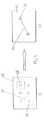
載物面12の上に配置されたおおむね二次元の物体10の測定装置のごく概要を図1に示す。物体10を下側から測定できるように、載物面12は本発明に基づき透明に、特にガラス板として形成されている。載物面12の下に映像処理検出器14が、座標測定装置のX及びY方向に調整し得るように配置されている。映像処理検出器はCCDマトリクスカメラ16からなり、特に大きな焦点深度を有するテレセントリック対物レンズの形の光学系18をこれに前置することが好ましい。 A very schematic overview of a measuring device for a generally two-
その場合載物面12はケースの面であって、映像処理検出器14はケースの中で物体14に対してX及びY方向に調整することができる。またケースの面は透明であり、ケースの面の上に物体10が直接載置されるか、又は面に対して等距離の間隔で平行をなす状態で配置される。 In this case, the loading surface 12 is the surface of the case, and the
移動する映像処理検出器14は物体10の下、かつ特にガラス板として形成された載物面12の下に、視線を物体10に向けて配置されているから、対物レンズ18の焦点深度が十分ならば、検出器16の焦点合わせはもはや必要でない。測定される物体区域、例えば本例では穴20の端縁は、物体12の厚さに関係なく同じ平面即ち載物面12にあり、この平面は映像処理検出器14の位置に関係なく、映像処理検出器14に対して一定不変の間隔を有するからである。 Since the moving
本例では物体10が載物面をなすガラス板上に直接配置されているが、物体10をガラス板から引き離して、これと平行をなす等距離の間隔で配置することももちろん可能である。 In this example, the
物体の照明のために物体の上側に、即ち映像処理検出器14に関して物体10の反対側に、特に偏平な発光パネル22の形の照明が設けられている。 Illumination in the form of a particularly flat light-emitting
その場合偏平な発光パネルはケースを閉じるカバーに組み込むものとする。この閉じた固定ケースの中に光学系18を備えた映像処理検出器14及び駆動装置が配置され、ケースの照明パネル側は透明部材例えばガラス板によって閉鎖され、ガラス板の上に測定物が配置される。また測定は通常、発光パネル22を含むカバーがケースを完全に隠蔽した時、即ちガラス板側を閉鎖した時にだけ行なわれる。カバーが載物面12を露出させると、物体10の測定が中止される。 In that case, the flat light-emitting panel is incorporated in a cover that closes the case. The
正確な測定を高速で行うために、本発明に基づき映像処理検出器14が物体10の測定区域の複数の位置24、26、28、30、32、34、36、38で映像を記録するようにした。図2a)及び3a)でこれらの映像は原則として映像処理検出器14のそれぞれの視野25、37に相当し、破線で囲んだ正方形で表され、次に映像記憶装置で各像を計算により組み合わせて図2b)の全体像とし、又は像を分散的に記録した場合(図3a))は図3b)の全測定像とする。次に各全体像40又は42から幾何学的特徴、例えば測定部位44、46の位置もしくは測定点又は測定部位の間隔を評価することができる。視野24、25、26、28、30、32、34、37、38は例えば50×80mm2の大きさ及び400×200mm2の測定範囲となる。但し本発明はこれに限定されるものではない。In order to make accurate measurements at high speed, according to the present invention, the
換言すれば測定時間の最適化のために本発明に基づき映像処理センサ、例えばマトリクスCCDカメラ16の位置を並列させることによって、選択に応じて全測定域(図2a))又は測定域の一部(図3a))が走査される。これに基づき接続された映像処理コンピュータで仮想的に全体像40、42が作られ、全体像で測定技術的評価が一挙に行われる。こうして位置決め操作が省略され、測定物10の全体的概観が得られる。この処置によって、マトリクス状の映像処理センサの正確な位置決めが不可欠であるという先行技術の欠点が回避される。 In other words, to optimize the measurement time, the position of the image processing sensor, for example the
これとは別に、まず映像処理センサを物体の測定位置におおまかに整列し、映像処理センサの整列の際にこれを加速a1>0mm/s2で移動し、次に映像処理センサを減速し、0mm/s2≦a2<a1の加速a2で映像処理センサを移動して上記の位置を測定することによって、測定方法を最適化することができる。その場合シャッタ付きCCDカメラの形の映像処理センサを使用することができ、それによって測定時にセンサの運動にかかわらずセンサの見掛けの停止が起こるという利点が生じる。同じことをフラッシュライトでも実現することができる。Separately, the image processing sensor is roughly aligned with the measurement position of the object, and when the image processing sensor is aligned, it is moved with acceleration a1 > 0 mm / s2 , and then the image processing sensor is decelerated. , 0 mm / s2 ≦ a2 <a1 by moving the image processing sensor with the acceleration a2 and measuring the above position, the measurement method can be optimized. In that case, an image processing sensor in the form of a CCD camera with a shutter can be used, which gives the advantage that the apparent stop of the sensor occurs during the measurement regardless of the movement of the sensor. The same can be achieved with a flashlight.
換言すれば、映像処理センサを測定位置にごくおおまかに移動し、次に映像処理センサを原則として加速せずに引続き移動し、例えば50ないし200mm/sの速度v1で移動して、測定するのである。その場合目標区域に到達することによって、測定のために必要な映像処理センサでの映像記憶を認識することができる。上記の位置を含む物体区域を映像処理センサで光学的に検出することによって、減速を開始することができる。In other words, the image processing sensor is moved roughly to the measurement position, and then the image processing sensor is continuously moved without being accelerated in principle, for example, moving at a speed v1 of 50 to 200 mm / s and measuring. It is. In that case, by reaching the target area, it is possible to recognize the video storage in the video processing sensor necessary for the measurement. Deceleration can be started by optically detecting an object area including the above position with a video processing sensor.
その場合映像処理センサの運動を次のように行うことができる。即ち速度v1で物体もしくは物体の測定区域又は測定点を測定し、続いて映像処理センサを例えば約5000ないし15000mm/sの値に大幅に加速し、次に加速0mm/s2で400ないし600mm/sの速度v2で測定区域又は測定点に対しておおまかに整列する。次に映像処理センサをとりわけ50mm/sないし150mm/sの範囲の速度v1に減速して測定する。この期間の間に物体又は測定区域にフラッシュライトを働かせ、又は映像処理センサのシャッタを所望の頻度で開閉する。測定を行った後、次に新しい測定点又は測定区域に対して整列するために、映像処理センサを前述のように加速する。In that case, the motion of the image processing sensor can be performed as follows. That is, an object or measurement area or measurement point of the object is measured at speed v1 , and then the image processing sensor is greatly accelerated to a value of, for example, about 5000 to 15000 mm / s, and then 400 to 600 mm at an acceleration of 0 mm / s2. Align roughly to the measurement area or measurement point at a velocity v2 of / s. Next, the image processing sensor is measured by decelerating to a speed v1 in the range of 50 mm / s to 150 mm / s. During this period, a flashlight is applied to the object or measurement area, or the shutter of the image processing sensor is opened and closed at a desired frequency. After taking a measurement, the image processing sensor is then accelerated as described above to align with a new measurement point or measurement area.
Claims (24)
Translated fromJapanese−映像処理センサ(14)を物体(10)の測定位置におおまかに整列させ、整列の際に映像処理センサを加速a1>0mm/s2で移動し、
−測定位置で映像処理センサを減速し、映像処理センサを0mm/s2≦a2<a1の加速a2で移動する
ことを特徴とする少なくとも請求項11に記載の方法。Perform the following procedure for measurement of the object (10) or area of the object: the image processing sensor (14) is roughly aligned with the measurement position of the object (10) and the image processing sensor is Moving with acceleration a1 > 0 mm / s2 ,
The method according to claim 11, wherein the image processing sensor is decelerated at the measurement position and the image processing sensor is moved at an acceleration a2 of 0 mm / s2 ≦ a2 <a1 .
An imaging optical system having a variable working distance, in particular, an imaging optical system having a zoom lens device including at least two sets of lens groups that can be electrically moved separately in the axial direction, is used. 15. The method according to 15.
Applications Claiming Priority (2)
| Application Number | Priority Date | Filing Date | Title |
|---|---|---|---|
| DE10211760ADE10211760A1 (en) | 2002-03-14 | 2002-03-14 | Arrangement and method for measuring geometries or structures of essentially two-dimensional objects by means of image processing sensors |
| PCT/EP2003/002719WO2003076871A2 (en) | 2002-03-14 | 2003-03-14 | Device and method for measuring geometries of essentially two-dimensional objects |
Publications (1)
| Publication Number | Publication Date |
|---|---|
| JP2005520128Atrue JP2005520128A (en) | 2005-07-07 |
Family
ID=27797845
Family Applications (1)
| Application Number | Title | Priority Date | Filing Date |
|---|---|---|---|
| JP2003575050APendingJP2005520128A (en) | 2002-03-14 | 2003-03-14 | Apparatus and method for measuring the geometry of a generally two-dimensional object. |
Country Status (7)
| Country | Link |
|---|---|
| US (1) | US20050033184A1 (en) |
| EP (1) | EP1481218B1 (en) |
| JP (1) | JP2005520128A (en) |
| CN (1) | CN1312460C (en) |
| AU (1) | AU2003239790A1 (en) |
| DE (1) | DE10211760A1 (en) |
| WO (1) | WO2003076871A2 (en) |
Families Citing this family (20)
| Publication number | Priority date | Publication date | Assignee | Title |
|---|---|---|---|---|
| DE10341666B4 (en)* | 2003-09-08 | 2011-01-13 | Werth Messtechnik Gmbh | Method for measuring geometries of essentially two-dimensional objects |
| DE102004058655B4 (en)* | 2004-09-07 | 2009-04-02 | Werth Messtechnik Gmbh | Method and arrangement for measuring geometries of an object by means of a coordinate measuring machine |
| EP1846729A1 (en)* | 2004-12-16 | 2007-10-24 | Werth Messtechnik GmbH | Coordinate measuring device and method for measuring with a coordinate measuring device |
| US8711365B2 (en) | 2004-12-16 | 2014-04-29 | Werth Messtechnik Gmbh | Coordinate measuring device and method for measuring with a coordinate measuring device |
| US9300883B2 (en)* | 2010-11-05 | 2016-03-29 | Examastica Co. | Imaging device, image processing method for image captured by imaging device, and imaging system |
| US10393505B2 (en) | 2013-12-06 | 2019-08-27 | Werth Messtechnik Gmbh | Device and method for measuring workpieces |
| DE102014117978A1 (en) | 2013-12-06 | 2015-06-11 | Werth Messtechnik Gmbh | Apparatus and method for measuring workpieces |
| CN107429997B (en)* | 2015-03-26 | 2019-10-11 | 卡尔蔡司工业测量技术有限公司 | Method and apparatus for determining the dimensional characteristic of measurement object |
| CN107548449B (en)* | 2015-04-21 | 2019-11-12 | 卡尔蔡司工业测量技术有限公司 | Method and apparatus for determining the actual size feature of measurand |
| US10410883B2 (en) | 2016-06-01 | 2019-09-10 | Corning Incorporated | Articles and methods of forming vias in substrates |
| DE102016209762A1 (en)* | 2016-06-03 | 2017-12-07 | Sms Group Gmbh | Device for measuring a thread |
| US10134657B2 (en) | 2016-06-29 | 2018-11-20 | Corning Incorporated | Inorganic wafer having through-holes attached to semiconductor wafer |
| US10794679B2 (en) | 2016-06-29 | 2020-10-06 | Corning Incorporated | Method and system for measuring geometric parameters of through holes |
| US11078112B2 (en) | 2017-05-25 | 2021-08-03 | Corning Incorporated | Silica-containing substrates with vias having an axially variable sidewall taper and methods for forming the same |
| US10580725B2 (en) | 2017-05-25 | 2020-03-03 | Corning Incorporated | Articles having vias with geometry attributes and methods for fabricating the same |
| US12180108B2 (en) | 2017-12-19 | 2024-12-31 | Corning Incorporated | Methods for etching vias in glass-based articles employing positive charge organic molecules |
| US11554984B2 (en) | 2018-02-22 | 2023-01-17 | Corning Incorporated | Alkali-free borosilicate glasses with low post-HF etch roughness |
| US11152294B2 (en) | 2018-04-09 | 2021-10-19 | Corning Incorporated | Hermetic metallized via with improved reliability |
| WO2020061437A1 (en) | 2018-09-20 | 2020-03-26 | Industrial Technology Research Institute | Copper metallization for through-glass vias on thin glass |
| CN113474311B (en) | 2019-02-21 | 2023-12-29 | 康宁股份有限公司 | Glass or glass ceramic article with copper-metallized through-holes and process for making same |
Family Cites Families (28)
| Publication number | Priority date | Publication date | Assignee | Title |
|---|---|---|---|---|
| US4092669A (en)* | 1975-05-31 | 1978-05-30 | Rolls-Royce (1971) Limited | Apparatus for measuring spatial data from recorded images |
| US4755746A (en)* | 1985-04-24 | 1988-07-05 | Prometrix Corporation | Apparatus and methods for semiconductor wafer testing |
| US4899296A (en)* | 1987-11-13 | 1990-02-06 | Khattak Anwar S | Pavement distress survey system |
| DE8802791U1 (en)* | 1988-03-02 | 1988-04-07 | Sigri GmbH, 8901 Meitingen | Lighting device for coordinate measuring machine |
| DK159088C (en)* | 1988-04-06 | 1991-01-28 | Oce Helioprint As | SCANNING TO DETECT AN ORIGINAL |
| DE3941144C2 (en)* | 1989-12-13 | 1994-01-13 | Zeiss Carl Fa | Coordinate measuring device for the contactless measurement of an object |
| US5523843A (en)* | 1990-07-09 | 1996-06-04 | Canon Kabushiki Kaisha | Position detecting system |
| US5251156A (en)* | 1990-08-25 | 1993-10-05 | Carl-Zeiss-Stiftung, Heidenheim/Brenz | Method and apparatus for non-contact measurement of object surfaces |
| US5420691A (en)* | 1991-03-15 | 1995-05-30 | Matsushita Electric Industrial Co., Ltd. | Electric component observation system |
| US5463464A (en)* | 1991-10-04 | 1995-10-31 | Kms Fusion, Inc. | Electro-optical system for gauging surface profile deviations using infrared radiation |
| US5452080A (en)* | 1993-06-04 | 1995-09-19 | Sony Corporation | Image inspection apparatus and method |
| US6407817B1 (en)* | 1993-12-20 | 2002-06-18 | Minolta Co., Ltd. | Measuring system with improved method of reading image data of an object |
| JPH0961111A (en)* | 1995-08-28 | 1997-03-07 | Nikon Corp | Pattern coordinate measuring method and device |
| CA2263226C (en)* | 1996-08-16 | 2006-10-10 | Imaging Research, Inc. | A digital imaging system for assays in well plates, gels and blots |
| DE19819492A1 (en)* | 1998-04-30 | 1999-11-11 | Leica Microsystems | Measuring device for measuring structures on a transparent substrate |
| US6242756B1 (en)* | 1998-05-21 | 2001-06-05 | Agilent Technologies, Inc | Cross optical axis inspection system for integrated circuits |
| US6201619B1 (en)* | 1998-06-18 | 2001-03-13 | Agfa Corporation | Autofocus process and system with fast multi-region sampling |
| US6956963B2 (en)* | 1998-07-08 | 2005-10-18 | Ismeca Europe Semiconductor Sa | Imaging for a machine-vision system |
| US6690473B1 (en)* | 1999-02-01 | 2004-02-10 | Sensys Instruments Corporation | Integrated surface metrology |
| DE19949008C2 (en)* | 1999-10-11 | 2003-12-11 | Leica Microsystems | Device and method for loading substrates of different sizes in substrate holders |
| DE19949019C2 (en)* | 1999-10-11 | 2001-12-13 | Leica Microsystems | Measuring device and method for measuring structures on substrates of various thicknesses |
| DE19948797C2 (en)* | 1999-10-11 | 2001-11-08 | Leica Microsystems | Substrate holder and use of the substrate holder in a high-precision measuring device |
| CN1230660C (en)* | 2000-09-22 | 2005-12-07 | 沃思测量技术股份有限公司 | Method for Measuring the Geometric Shape of Objects with Coordinate Measuring Instruments |
| DE20017739U1 (en)* | 2000-10-16 | 2001-01-11 | Mycrona Gesellschaft für innovative Messtechnik mbH, 66793 Saarwellingen | Devices for the optical measurement of an object, with a coordinate measuring machine with a camera |
| DE50214661D1 (en)* | 2001-07-16 | 2010-10-28 | Werth Messtechnik Gmbh | METHOD FOR MEASURING AN OBJECT WITH A COORDINATE MEASURING DEVICE WITH IMAGE PROCESSING SENSOR |
| JP2004535580A (en)* | 2001-07-16 | 2004-11-25 | ベルス・メステヒニーク・ゲーエムベーハー | Surface characteristic measuring method and coordinate measuring device |
| US6788406B2 (en)* | 2001-11-02 | 2004-09-07 | Delaware Capital Formation, Inc. | Device and methods of inspecting soldered connections |
| DE10211070A1 (en)* | 2002-03-13 | 2003-09-25 | Gurny Broesch Andrea | Device for measuring a measurement object |
- 2002
- 2002-03-14DEDE10211760Apatent/DE10211760A1/ennot_activeWithdrawn
- 2003
- 2003-03-14JPJP2003575050Apatent/JP2005520128A/enactivePending
- 2003-03-14AUAU2003239790Apatent/AU2003239790A1/ennot_activeAbandoned
- 2003-03-14WOPCT/EP2003/002719patent/WO2003076871A2/enactiveApplication Filing
- 2003-03-14EPEP03732267Apatent/EP1481218B1/ennot_activeExpired - Lifetime
- 2003-03-14USUS10/499,816patent/US20050033184A1/ennot_activeAbandoned
- 2003-03-14CNCNB038060256Apatent/CN1312460C/ennot_activeExpired - Fee Related
Also Published As
| Publication number | Publication date |
|---|---|
| CN1643339A (en) | 2005-07-20 |
| EP1481218B1 (en) | 2012-12-19 |
| AU2003239790A1 (en) | 2003-09-22 |
| US20050033184A1 (en) | 2005-02-10 |
| WO2003076871A3 (en) | 2003-12-24 |
| CN1312460C (en) | 2007-04-25 |
| WO2003076871A2 (en) | 2003-09-18 |
| DE10211760A1 (en) | 2003-10-02 |
| AU2003239790A8 (en) | 2003-09-22 |
| EP1481218A2 (en) | 2004-12-01 |
Similar Documents
| Publication | Publication Date | Title |
|---|---|---|
| JP2005520128A (en) | Apparatus and method for measuring the geometry of a generally two-dimensional object. | |
| US6094269A (en) | Apparatus and method for optically measuring an object surface contour | |
| US4829373A (en) | Stereo mensuration apparatus | |
| US6549288B1 (en) | Structured-light, triangulation-based three-dimensional digitizer | |
| US10455137B2 (en) | Auto-focus system | |
| CN103765277B (en) | Use the focusing of error signal and imaging system and technology | |
| US6291817B1 (en) | Moire apparatus having projection optical system and observation optical system which have optical axes parallel to each other | |
| CN108225190A (en) | Measuring system | |
| JP2514928B2 (en) | Photogrammetric subject detection method | |
| JP2015230393A (en) | Imaging device control method and imaging system | |
| JPH11166818A (en) | Calibrating method and device for three-dimensional shape measuring device | |
| US4849912A (en) | Stereo mensuration method | |
| US4809066A (en) | Method of image mensuration with selectively visible and invisible reseau grid marks | |
| US6927864B2 (en) | Method and system for determining dimensions of optically recognizable features | |
| KR950703728A (en) | PROCESS AND ASSEMBLY FOR MEASURING AN ARTICLE'S DIMENSIONS | |
| US5568258A (en) | Method and device for measuring distortion of a transmitting beam or a surface shape of a three-dimensional object | |
| US4924505A (en) | Method of mensuration of an image on an object | |
| US4928169A (en) | Mensuration frame grabbing apparatus | |
| US4897678A (en) | Double z-axis translational mounting apparatus for camera in photogrammetry mensuration systems | |
| JPH071164B2 (en) | 3D shape recognition device | |
| JPH06207812A (en) | Measurement point indicator for three-dimensional measurement | |
| US4841455A (en) | Reseau apparatus for photogrammetry devices | |
| JPH08334438A (en) | Headlight tester | |
| JPH07208917A (en) | Automatic focusing method and device | |
| KR20160125884A (en) | Measuring apparatus |
Legal Events
| Date | Code | Title | Description |
|---|---|---|---|
| A621 | Written request for application examination | Free format text:JAPANESE INTERMEDIATE CODE: A621 Effective date:20060214 | |
| A977 | Report on retrieval | Free format text:JAPANESE INTERMEDIATE CODE: A971007 Effective date:20080124 | |
| A131 | Notification of reasons for refusal | Free format text:JAPANESE INTERMEDIATE CODE: A131 Effective date:20080129 | |
| A601 | Written request for extension of time | Free format text:JAPANESE INTERMEDIATE CODE: A601 Effective date:20080411 | |
| A602 | Written permission of extension of time | Free format text:JAPANESE INTERMEDIATE CODE: A602 Effective date:20080418 | |
| A521 | Request for written amendment filed | Free format text:JAPANESE INTERMEDIATE CODE: A523 Effective date:20080729 | |
| A131 | Notification of reasons for refusal | Free format text:JAPANESE INTERMEDIATE CODE: A131 Effective date:20081125 | |
| A601 | Written request for extension of time | Free format text:JAPANESE INTERMEDIATE CODE: A601 Effective date:20090220 | |
| A602 | Written permission of extension of time | Free format text:JAPANESE INTERMEDIATE CODE: A602 Effective date:20090227 | |
| A02 | Decision of refusal | Free format text:JAPANESE INTERMEDIATE CODE: A02 Effective date:20090714 |