JP2005519696A - Instruments and methods for implanting spinal implant devices - Google Patents
Instruments and methods for implanting spinal implant devicesDownload PDFInfo
- Publication number
- JP2005519696A JP2005519696AJP2003575864AJP2003575864AJP2005519696AJP 2005519696 AJP2005519696 AJP 2005519696AJP 2003575864 AJP2003575864 AJP 2003575864AJP 2003575864 AJP2003575864 AJP 2003575864AJP 2005519696 AJP2005519696 AJP 2005519696A
- Authority
- JP
- Japan
- Prior art keywords
- implant
- spreader
- separator
- connector
- implant member
- Prior art date
- Legal status (The legal status is an assumption and is not a legal conclusion. Google has not performed a legal analysis and makes no representation as to the accuracy of the status listed.)
- Granted
Links
- 0C=*1CCCC1Chemical compoundC=*1CCCC10.000description1
Images


Classifications
- A—HUMAN NECESSITIES
- A61—MEDICAL OR VETERINARY SCIENCE; HYGIENE
- A61F—FILTERS IMPLANTABLE INTO BLOOD VESSELS; PROSTHESES; DEVICES PROVIDING PATENCY TO, OR PREVENTING COLLAPSING OF, TUBULAR STRUCTURES OF THE BODY, e.g. STENTS; ORTHOPAEDIC, NURSING OR CONTRACEPTIVE DEVICES; FOMENTATION; TREATMENT OR PROTECTION OF EYES OR EARS; BANDAGES, DRESSINGS OR ABSORBENT PADS; FIRST-AID KITS
- A61F2/00—Filters implantable into blood vessels; Prostheses, i.e. artificial substitutes or replacements for parts of the body; Appliances for connecting them with the body; Devices providing patency to, or preventing collapsing of, tubular structures of the body, e.g. stents
- A61F2/02—Prostheses implantable into the body
- A61F2/30—Joints
- A61F2/46—Special tools for implanting artificial joints
- A61F2/4657—Measuring instruments used for implanting artificial joints
- A—HUMAN NECESSITIES
- A61—MEDICAL OR VETERINARY SCIENCE; HYGIENE
- A61B—DIAGNOSIS; SURGERY; IDENTIFICATION
- A61B17/00—Surgical instruments, devices or methods
- A61B17/02—Surgical instruments, devices or methods for holding wounds open, e.g. retractors; Tractors
- A61B17/025—Joint distractors
- A—HUMAN NECESSITIES
- A61—MEDICAL OR VETERINARY SCIENCE; HYGIENE
- A61F—FILTERS IMPLANTABLE INTO BLOOD VESSELS; PROSTHESES; DEVICES PROVIDING PATENCY TO, OR PREVENTING COLLAPSING OF, TUBULAR STRUCTURES OF THE BODY, e.g. STENTS; ORTHOPAEDIC, NURSING OR CONTRACEPTIVE DEVICES; FOMENTATION; TREATMENT OR PROTECTION OF EYES OR EARS; BANDAGES, DRESSINGS OR ABSORBENT PADS; FIRST-AID KITS
- A61F2/00—Filters implantable into blood vessels; Prostheses, i.e. artificial substitutes or replacements for parts of the body; Appliances for connecting them with the body; Devices providing patency to, or preventing collapsing of, tubular structures of the body, e.g. stents
- A61F2/02—Prostheses implantable into the body
- A61F2/30—Joints
- A61F2/44—Joints for the spine, e.g. vertebrae, spinal discs
- A61F2/442—Intervertebral or spinal discs, e.g. resilient
- A—HUMAN NECESSITIES
- A61—MEDICAL OR VETERINARY SCIENCE; HYGIENE
- A61F—FILTERS IMPLANTABLE INTO BLOOD VESSELS; PROSTHESES; DEVICES PROVIDING PATENCY TO, OR PREVENTING COLLAPSING OF, TUBULAR STRUCTURES OF THE BODY, e.g. STENTS; ORTHOPAEDIC, NURSING OR CONTRACEPTIVE DEVICES; FOMENTATION; TREATMENT OR PROTECTION OF EYES OR EARS; BANDAGES, DRESSINGS OR ABSORBENT PADS; FIRST-AID KITS
- A61F2/00—Filters implantable into blood vessels; Prostheses, i.e. artificial substitutes or replacements for parts of the body; Appliances for connecting them with the body; Devices providing patency to, or preventing collapsing of, tubular structures of the body, e.g. stents
- A61F2/02—Prostheses implantable into the body
- A61F2/30—Joints
- A61F2/44—Joints for the spine, e.g. vertebrae, spinal discs
- A61F2/4455—Joints for the spine, e.g. vertebrae, spinal discs for the fusion of spinal bodies, e.g. intervertebral fusion of adjacent spinal bodies, e.g. fusion cages
- A61F2/447—Joints for the spine, e.g. vertebrae, spinal discs for the fusion of spinal bodies, e.g. intervertebral fusion of adjacent spinal bodies, e.g. fusion cages substantially parallelepipedal, e.g. having a rectangular or trapezoidal cross-section
- A—HUMAN NECESSITIES
- A61—MEDICAL OR VETERINARY SCIENCE; HYGIENE
- A61F—FILTERS IMPLANTABLE INTO BLOOD VESSELS; PROSTHESES; DEVICES PROVIDING PATENCY TO, OR PREVENTING COLLAPSING OF, TUBULAR STRUCTURES OF THE BODY, e.g. STENTS; ORTHOPAEDIC, NURSING OR CONTRACEPTIVE DEVICES; FOMENTATION; TREATMENT OR PROTECTION OF EYES OR EARS; BANDAGES, DRESSINGS OR ABSORBENT PADS; FIRST-AID KITS
- A61F2/00—Filters implantable into blood vessels; Prostheses, i.e. artificial substitutes or replacements for parts of the body; Appliances for connecting them with the body; Devices providing patency to, or preventing collapsing of, tubular structures of the body, e.g. stents
- A61F2/02—Prostheses implantable into the body
- A61F2/30—Joints
- A61F2/46—Special tools for implanting artificial joints
- A61F2/4603—Special tools for implanting artificial joints for insertion or extraction of endoprosthetic joints or of accessories thereof
- A61F2/4611—Special tools for implanting artificial joints for insertion or extraction of endoprosthetic joints or of accessories thereof of spinal prostheses
- A—HUMAN NECESSITIES
- A61—MEDICAL OR VETERINARY SCIENCE; HYGIENE
- A61B—DIAGNOSIS; SURGERY; IDENTIFICATION
- A61B17/00—Surgical instruments, devices or methods
- A61B17/02—Surgical instruments, devices or methods for holding wounds open, e.g. retractors; Tractors
- A61B17/0206—Surgical instruments, devices or methods for holding wounds open, e.g. retractors; Tractors with antagonistic arms as supports for retractor elements
- A—HUMAN NECESSITIES
- A61—MEDICAL OR VETERINARY SCIENCE; HYGIENE
- A61B—DIAGNOSIS; SURGERY; IDENTIFICATION
- A61B17/00—Surgical instruments, devices or methods
- A61B17/02—Surgical instruments, devices or methods for holding wounds open, e.g. retractors; Tractors
- A61B17/025—Joint distractors
- A61B2017/0256—Joint distractors for the spine
- A—HUMAN NECESSITIES
- A61—MEDICAL OR VETERINARY SCIENCE; HYGIENE
- A61B—DIAGNOSIS; SURGERY; IDENTIFICATION
- A61B90/00—Instruments, implements or accessories specially adapted for surgery or diagnosis and not covered by any of the groups A61B1/00 - A61B50/00, e.g. for luxation treatment or for protecting wound edges
- A61B90/06—Measuring instruments not otherwise provided for
- A61B2090/062—Measuring instruments not otherwise provided for penetration depth
- A—HUMAN NECESSITIES
- A61—MEDICAL OR VETERINARY SCIENCE; HYGIENE
- A61F—FILTERS IMPLANTABLE INTO BLOOD VESSELS; PROSTHESES; DEVICES PROVIDING PATENCY TO, OR PREVENTING COLLAPSING OF, TUBULAR STRUCTURES OF THE BODY, e.g. STENTS; ORTHOPAEDIC, NURSING OR CONTRACEPTIVE DEVICES; FOMENTATION; TREATMENT OR PROTECTION OF EYES OR EARS; BANDAGES, DRESSINGS OR ABSORBENT PADS; FIRST-AID KITS
- A61F2/00—Filters implantable into blood vessels; Prostheses, i.e. artificial substitutes or replacements for parts of the body; Appliances for connecting them with the body; Devices providing patency to, or preventing collapsing of, tubular structures of the body, e.g. stents
- A61F2/02—Prostheses implantable into the body
- A61F2/28—Bones
- A—HUMAN NECESSITIES
- A61—MEDICAL OR VETERINARY SCIENCE; HYGIENE
- A61F—FILTERS IMPLANTABLE INTO BLOOD VESSELS; PROSTHESES; DEVICES PROVIDING PATENCY TO, OR PREVENTING COLLAPSING OF, TUBULAR STRUCTURES OF THE BODY, e.g. STENTS; ORTHOPAEDIC, NURSING OR CONTRACEPTIVE DEVICES; FOMENTATION; TREATMENT OR PROTECTION OF EYES OR EARS; BANDAGES, DRESSINGS OR ABSORBENT PADS; FIRST-AID KITS
- A61F2/00—Filters implantable into blood vessels; Prostheses, i.e. artificial substitutes or replacements for parts of the body; Appliances for connecting them with the body; Devices providing patency to, or preventing collapsing of, tubular structures of the body, e.g. stents
- A61F2/02—Prostheses implantable into the body
- A61F2/30—Joints
- A61F2/46—Special tools for implanting artificial joints
- A61F2/4603—Special tools for implanting artificial joints for insertion or extraction of endoprosthetic joints or of accessories thereof
- A—HUMAN NECESSITIES
- A61—MEDICAL OR VETERINARY SCIENCE; HYGIENE
- A61F—FILTERS IMPLANTABLE INTO BLOOD VESSELS; PROSTHESES; DEVICES PROVIDING PATENCY TO, OR PREVENTING COLLAPSING OF, TUBULAR STRUCTURES OF THE BODY, e.g. STENTS; ORTHOPAEDIC, NURSING OR CONTRACEPTIVE DEVICES; FOMENTATION; TREATMENT OR PROTECTION OF EYES OR EARS; BANDAGES, DRESSINGS OR ABSORBENT PADS; FIRST-AID KITS
- A61F2/00—Filters implantable into blood vessels; Prostheses, i.e. artificial substitutes or replacements for parts of the body; Appliances for connecting them with the body; Devices providing patency to, or preventing collapsing of, tubular structures of the body, e.g. stents
- A61F2/02—Prostheses implantable into the body
- A61F2/30—Joints
- A61F2/46—Special tools for implanting artificial joints
- A61F2/4684—Trial or dummy prostheses
- A—HUMAN NECESSITIES
- A61—MEDICAL OR VETERINARY SCIENCE; HYGIENE
- A61F—FILTERS IMPLANTABLE INTO BLOOD VESSELS; PROSTHESES; DEVICES PROVIDING PATENCY TO, OR PREVENTING COLLAPSING OF, TUBULAR STRUCTURES OF THE BODY, e.g. STENTS; ORTHOPAEDIC, NURSING OR CONTRACEPTIVE DEVICES; FOMENTATION; TREATMENT OR PROTECTION OF EYES OR EARS; BANDAGES, DRESSINGS OR ABSORBENT PADS; FIRST-AID KITS
- A61F2/00—Filters implantable into blood vessels; Prostheses, i.e. artificial substitutes or replacements for parts of the body; Appliances for connecting them with the body; Devices providing patency to, or preventing collapsing of, tubular structures of the body, e.g. stents
- A61F2/02—Prostheses implantable into the body
- A61F2/28—Bones
- A61F2002/2835—Bone graft implants for filling a bony defect or an endoprosthesis cavity, e.g. by synthetic material or biological material
- A—HUMAN NECESSITIES
- A61—MEDICAL OR VETERINARY SCIENCE; HYGIENE
- A61F—FILTERS IMPLANTABLE INTO BLOOD VESSELS; PROSTHESES; DEVICES PROVIDING PATENCY TO, OR PREVENTING COLLAPSING OF, TUBULAR STRUCTURES OF THE BODY, e.g. STENTS; ORTHOPAEDIC, NURSING OR CONTRACEPTIVE DEVICES; FOMENTATION; TREATMENT OR PROTECTION OF EYES OR EARS; BANDAGES, DRESSINGS OR ABSORBENT PADS; FIRST-AID KITS
- A61F2/00—Filters implantable into blood vessels; Prostheses, i.e. artificial substitutes or replacements for parts of the body; Appliances for connecting them with the body; Devices providing patency to, or preventing collapsing of, tubular structures of the body, e.g. stents
- A61F2/02—Prostheses implantable into the body
- A61F2/30—Joints
- A61F2002/30001—Additional features of subject-matter classified in A61F2/28, A61F2/30 and subgroups thereof
- A61F2002/30003—Material related properties of the prosthesis or of a coating on the prosthesis
- A61F2002/3006—Properties of materials and coating materials
- A61F2002/30062—(bio)absorbable, biodegradable, bioerodable, (bio)resorbable, resorptive
- A—HUMAN NECESSITIES
- A61—MEDICAL OR VETERINARY SCIENCE; HYGIENE
- A61F—FILTERS IMPLANTABLE INTO BLOOD VESSELS; PROSTHESES; DEVICES PROVIDING PATENCY TO, OR PREVENTING COLLAPSING OF, TUBULAR STRUCTURES OF THE BODY, e.g. STENTS; ORTHOPAEDIC, NURSING OR CONTRACEPTIVE DEVICES; FOMENTATION; TREATMENT OR PROTECTION OF EYES OR EARS; BANDAGES, DRESSINGS OR ABSORBENT PADS; FIRST-AID KITS
- A61F2/00—Filters implantable into blood vessels; Prostheses, i.e. artificial substitutes or replacements for parts of the body; Appliances for connecting them with the body; Devices providing patency to, or preventing collapsing of, tubular structures of the body, e.g. stents
- A61F2/02—Prostheses implantable into the body
- A61F2/30—Joints
- A61F2002/30001—Additional features of subject-matter classified in A61F2/28, A61F2/30 and subgroups thereof
- A61F2002/30108—Shapes
- A61F2002/30199—Three-dimensional shapes
- A61F2002/30261—Three-dimensional shapes parallelepipedal
- A61F2002/30266—Three-dimensional shapes parallelepipedal wedge-shaped parallelepipeds
- A—HUMAN NECESSITIES
- A61—MEDICAL OR VETERINARY SCIENCE; HYGIENE
- A61F—FILTERS IMPLANTABLE INTO BLOOD VESSELS; PROSTHESES; DEVICES PROVIDING PATENCY TO, OR PREVENTING COLLAPSING OF, TUBULAR STRUCTURES OF THE BODY, e.g. STENTS; ORTHOPAEDIC, NURSING OR CONTRACEPTIVE DEVICES; FOMENTATION; TREATMENT OR PROTECTION OF EYES OR EARS; BANDAGES, DRESSINGS OR ABSORBENT PADS; FIRST-AID KITS
- A61F2/00—Filters implantable into blood vessels; Prostheses, i.e. artificial substitutes or replacements for parts of the body; Appliances for connecting them with the body; Devices providing patency to, or preventing collapsing of, tubular structures of the body, e.g. stents
- A61F2/02—Prostheses implantable into the body
- A61F2/30—Joints
- A61F2002/30001—Additional features of subject-matter classified in A61F2/28, A61F2/30 and subgroups thereof
- A61F2002/30316—The prosthesis having different structural features at different locations within the same prosthesis; Connections between prosthetic parts; Special structural features of bone or joint prostheses not otherwise provided for
- A61F2002/30329—Connections or couplings between prosthetic parts, e.g. between modular parts; Connecting elements
- A61F2002/30383—Connections or couplings between prosthetic parts, e.g. between modular parts; Connecting elements made by laterally inserting a protrusion, e.g. a rib into a complementarily-shaped groove
- A61F2002/30385—Connections or couplings between prosthetic parts, e.g. between modular parts; Connecting elements made by laterally inserting a protrusion, e.g. a rib into a complementarily-shaped groove the rib and groove having non-parallel, e.g. conically-tapered, cooperating sides, e.g. having a trapezoidal front cross-section
- A—HUMAN NECESSITIES
- A61—MEDICAL OR VETERINARY SCIENCE; HYGIENE
- A61F—FILTERS IMPLANTABLE INTO BLOOD VESSELS; PROSTHESES; DEVICES PROVIDING PATENCY TO, OR PREVENTING COLLAPSING OF, TUBULAR STRUCTURES OF THE BODY, e.g. STENTS; ORTHOPAEDIC, NURSING OR CONTRACEPTIVE DEVICES; FOMENTATION; TREATMENT OR PROTECTION OF EYES OR EARS; BANDAGES, DRESSINGS OR ABSORBENT PADS; FIRST-AID KITS
- A61F2/00—Filters implantable into blood vessels; Prostheses, i.e. artificial substitutes or replacements for parts of the body; Appliances for connecting them with the body; Devices providing patency to, or preventing collapsing of, tubular structures of the body, e.g. stents
- A61F2/02—Prostheses implantable into the body
- A61F2/30—Joints
- A61F2002/30001—Additional features of subject-matter classified in A61F2/28, A61F2/30 and subgroups thereof
- A61F2002/30316—The prosthesis having different structural features at different locations within the same prosthesis; Connections between prosthetic parts; Special structural features of bone or joint prostheses not otherwise provided for
- A61F2002/30329—Connections or couplings between prosthetic parts, e.g. between modular parts; Connecting elements
- A61F2002/30383—Connections or couplings between prosthetic parts, e.g. between modular parts; Connecting elements made by laterally inserting a protrusion, e.g. a rib into a complementarily-shaped groove
- A61F2002/30387—Dovetail connection
- A—HUMAN NECESSITIES
- A61—MEDICAL OR VETERINARY SCIENCE; HYGIENE
- A61F—FILTERS IMPLANTABLE INTO BLOOD VESSELS; PROSTHESES; DEVICES PROVIDING PATENCY TO, OR PREVENTING COLLAPSING OF, TUBULAR STRUCTURES OF THE BODY, e.g. STENTS; ORTHOPAEDIC, NURSING OR CONTRACEPTIVE DEVICES; FOMENTATION; TREATMENT OR PROTECTION OF EYES OR EARS; BANDAGES, DRESSINGS OR ABSORBENT PADS; FIRST-AID KITS
- A61F2/00—Filters implantable into blood vessels; Prostheses, i.e. artificial substitutes or replacements for parts of the body; Appliances for connecting them with the body; Devices providing patency to, or preventing collapsing of, tubular structures of the body, e.g. stents
- A61F2/02—Prostheses implantable into the body
- A61F2/30—Joints
- A61F2002/30001—Additional features of subject-matter classified in A61F2/28, A61F2/30 and subgroups thereof
- A61F2002/30316—The prosthesis having different structural features at different locations within the same prosthesis; Connections between prosthetic parts; Special structural features of bone or joint prostheses not otherwise provided for
- A61F2002/30329—Connections or couplings between prosthetic parts, e.g. between modular parts; Connecting elements
- A61F2002/30471—Connections or couplings between prosthetic parts, e.g. between modular parts; Connecting elements connected by a hinged linkage mechanism, e.g. of the single-bar or multi-bar linkage type
- A—HUMAN NECESSITIES
- A61—MEDICAL OR VETERINARY SCIENCE; HYGIENE
- A61F—FILTERS IMPLANTABLE INTO BLOOD VESSELS; PROSTHESES; DEVICES PROVIDING PATENCY TO, OR PREVENTING COLLAPSING OF, TUBULAR STRUCTURES OF THE BODY, e.g. STENTS; ORTHOPAEDIC, NURSING OR CONTRACEPTIVE DEVICES; FOMENTATION; TREATMENT OR PROTECTION OF EYES OR EARS; BANDAGES, DRESSINGS OR ABSORBENT PADS; FIRST-AID KITS
- A61F2/00—Filters implantable into blood vessels; Prostheses, i.e. artificial substitutes or replacements for parts of the body; Appliances for connecting them with the body; Devices providing patency to, or preventing collapsing of, tubular structures of the body, e.g. stents
- A61F2/02—Prostheses implantable into the body
- A61F2/30—Joints
- A61F2002/30001—Additional features of subject-matter classified in A61F2/28, A61F2/30 and subgroups thereof
- A61F2002/30316—The prosthesis having different structural features at different locations within the same prosthesis; Connections between prosthetic parts; Special structural features of bone or joint prostheses not otherwise provided for
- A61F2002/30329—Connections or couplings between prosthetic parts, e.g. between modular parts; Connecting elements
- A61F2002/30476—Connections or couplings between prosthetic parts, e.g. between modular parts; Connecting elements locked by an additional locking mechanism
- A61F2002/305—Snap connection
- A—HUMAN NECESSITIES
- A61—MEDICAL OR VETERINARY SCIENCE; HYGIENE
- A61F—FILTERS IMPLANTABLE INTO BLOOD VESSELS; PROSTHESES; DEVICES PROVIDING PATENCY TO, OR PREVENTING COLLAPSING OF, TUBULAR STRUCTURES OF THE BODY, e.g. STENTS; ORTHOPAEDIC, NURSING OR CONTRACEPTIVE DEVICES; FOMENTATION; TREATMENT OR PROTECTION OF EYES OR EARS; BANDAGES, DRESSINGS OR ABSORBENT PADS; FIRST-AID KITS
- A61F2/00—Filters implantable into blood vessels; Prostheses, i.e. artificial substitutes or replacements for parts of the body; Appliances for connecting them with the body; Devices providing patency to, or preventing collapsing of, tubular structures of the body, e.g. stents
- A61F2/02—Prostheses implantable into the body
- A61F2/30—Joints
- A61F2002/30001—Additional features of subject-matter classified in A61F2/28, A61F2/30 and subgroups thereof
- A61F2002/30316—The prosthesis having different structural features at different locations within the same prosthesis; Connections between prosthetic parts; Special structural features of bone or joint prostheses not otherwise provided for
- A61F2002/30329—Connections or couplings between prosthetic parts, e.g. between modular parts; Connecting elements
- A61F2002/30476—Connections or couplings between prosthetic parts, e.g. between modular parts; Connecting elements locked by an additional locking mechanism
- A61F2002/30507—Connections or couplings between prosthetic parts, e.g. between modular parts; Connecting elements locked by an additional locking mechanism using a threaded locking member, e.g. a locking screw or a set screw
- A—HUMAN NECESSITIES
- A61—MEDICAL OR VETERINARY SCIENCE; HYGIENE
- A61F—FILTERS IMPLANTABLE INTO BLOOD VESSELS; PROSTHESES; DEVICES PROVIDING PATENCY TO, OR PREVENTING COLLAPSING OF, TUBULAR STRUCTURES OF THE BODY, e.g. STENTS; ORTHOPAEDIC, NURSING OR CONTRACEPTIVE DEVICES; FOMENTATION; TREATMENT OR PROTECTION OF EYES OR EARS; BANDAGES, DRESSINGS OR ABSORBENT PADS; FIRST-AID KITS
- A61F2/00—Filters implantable into blood vessels; Prostheses, i.e. artificial substitutes or replacements for parts of the body; Appliances for connecting them with the body; Devices providing patency to, or preventing collapsing of, tubular structures of the body, e.g. stents
- A61F2/02—Prostheses implantable into the body
- A61F2/30—Joints
- A61F2002/30001—Additional features of subject-matter classified in A61F2/28, A61F2/30 and subgroups thereof
- A61F2002/30316—The prosthesis having different structural features at different locations within the same prosthesis; Connections between prosthetic parts; Special structural features of bone or joint prostheses not otherwise provided for
- A61F2002/30535—Special structural features of bone or joint prostheses not otherwise provided for
- A61F2002/30565—Special structural features of bone or joint prostheses not otherwise provided for having spring elements
- A—HUMAN NECESSITIES
- A61—MEDICAL OR VETERINARY SCIENCE; HYGIENE
- A61F—FILTERS IMPLANTABLE INTO BLOOD VESSELS; PROSTHESES; DEVICES PROVIDING PATENCY TO, OR PREVENTING COLLAPSING OF, TUBULAR STRUCTURES OF THE BODY, e.g. STENTS; ORTHOPAEDIC, NURSING OR CONTRACEPTIVE DEVICES; FOMENTATION; TREATMENT OR PROTECTION OF EYES OR EARS; BANDAGES, DRESSINGS OR ABSORBENT PADS; FIRST-AID KITS
- A61F2/00—Filters implantable into blood vessels; Prostheses, i.e. artificial substitutes or replacements for parts of the body; Appliances for connecting them with the body; Devices providing patency to, or preventing collapsing of, tubular structures of the body, e.g. stents
- A61F2/02—Prostheses implantable into the body
- A61F2/30—Joints
- A61F2002/30001—Additional features of subject-matter classified in A61F2/28, A61F2/30 and subgroups thereof
- A61F2002/30316—The prosthesis having different structural features at different locations within the same prosthesis; Connections between prosthetic parts; Special structural features of bone or joint prostheses not otherwise provided for
- A61F2002/30535—Special structural features of bone or joint prostheses not otherwise provided for
- A61F2002/30604—Special structural features of bone or joint prostheses not otherwise provided for modular
- A61F2002/30616—Sets comprising a plurality of prosthetic parts of different sizes or orientations
- A—HUMAN NECESSITIES
- A61—MEDICAL OR VETERINARY SCIENCE; HYGIENE
- A61F—FILTERS IMPLANTABLE INTO BLOOD VESSELS; PROSTHESES; DEVICES PROVIDING PATENCY TO, OR PREVENTING COLLAPSING OF, TUBULAR STRUCTURES OF THE BODY, e.g. STENTS; ORTHOPAEDIC, NURSING OR CONTRACEPTIVE DEVICES; FOMENTATION; TREATMENT OR PROTECTION OF EYES OR EARS; BANDAGES, DRESSINGS OR ABSORBENT PADS; FIRST-AID KITS
- A61F2/00—Filters implantable into blood vessels; Prostheses, i.e. artificial substitutes or replacements for parts of the body; Appliances for connecting them with the body; Devices providing patency to, or preventing collapsing of, tubular structures of the body, e.g. stents
- A61F2/02—Prostheses implantable into the body
- A61F2/30—Joints
- A61F2002/30001—Additional features of subject-matter classified in A61F2/28, A61F2/30 and subgroups thereof
- A61F2002/30667—Features concerning an interaction with the environment or a particular use of the prosthesis
- A61F2002/3071—Identification means; Administration of patients
- A—HUMAN NECESSITIES
- A61—MEDICAL OR VETERINARY SCIENCE; HYGIENE
- A61F—FILTERS IMPLANTABLE INTO BLOOD VESSELS; PROSTHESES; DEVICES PROVIDING PATENCY TO, OR PREVENTING COLLAPSING OF, TUBULAR STRUCTURES OF THE BODY, e.g. STENTS; ORTHOPAEDIC, NURSING OR CONTRACEPTIVE DEVICES; FOMENTATION; TREATMENT OR PROTECTION OF EYES OR EARS; BANDAGES, DRESSINGS OR ABSORBENT PADS; FIRST-AID KITS
- A61F2/00—Filters implantable into blood vessels; Prostheses, i.e. artificial substitutes or replacements for parts of the body; Appliances for connecting them with the body; Devices providing patency to, or preventing collapsing of, tubular structures of the body, e.g. stents
- A61F2/02—Prostheses implantable into the body
- A61F2/30—Joints
- A61F2/30767—Special external or bone-contacting surface, e.g. coating for improving bone ingrowth
- A61F2/30771—Special external or bone-contacting surface, e.g. coating for improving bone ingrowth applied in original prostheses, e.g. holes or grooves
- A61F2002/30772—Apertures or holes, e.g. of circular cross section
- A61F2002/30784—Plurality of holes
- A—HUMAN NECESSITIES
- A61—MEDICAL OR VETERINARY SCIENCE; HYGIENE
- A61F—FILTERS IMPLANTABLE INTO BLOOD VESSELS; PROSTHESES; DEVICES PROVIDING PATENCY TO, OR PREVENTING COLLAPSING OF, TUBULAR STRUCTURES OF THE BODY, e.g. STENTS; ORTHOPAEDIC, NURSING OR CONTRACEPTIVE DEVICES; FOMENTATION; TREATMENT OR PROTECTION OF EYES OR EARS; BANDAGES, DRESSINGS OR ABSORBENT PADS; FIRST-AID KITS
- A61F2/00—Filters implantable into blood vessels; Prostheses, i.e. artificial substitutes or replacements for parts of the body; Appliances for connecting them with the body; Devices providing patency to, or preventing collapsing of, tubular structures of the body, e.g. stents
- A61F2/02—Prostheses implantable into the body
- A61F2/30—Joints
- A61F2/30767—Special external or bone-contacting surface, e.g. coating for improving bone ingrowth
- A61F2/30771—Special external or bone-contacting surface, e.g. coating for improving bone ingrowth applied in original prostheses, e.g. holes or grooves
- A61F2002/3082—Grooves
- A61F2002/30823—Grooves having the shape of a reverse dovetail
- A—HUMAN NECESSITIES
- A61—MEDICAL OR VETERINARY SCIENCE; HYGIENE
- A61F—FILTERS IMPLANTABLE INTO BLOOD VESSELS; PROSTHESES; DEVICES PROVIDING PATENCY TO, OR PREVENTING COLLAPSING OF, TUBULAR STRUCTURES OF THE BODY, e.g. STENTS; ORTHOPAEDIC, NURSING OR CONTRACEPTIVE DEVICES; FOMENTATION; TREATMENT OR PROTECTION OF EYES OR EARS; BANDAGES, DRESSINGS OR ABSORBENT PADS; FIRST-AID KITS
- A61F2/00—Filters implantable into blood vessels; Prostheses, i.e. artificial substitutes or replacements for parts of the body; Appliances for connecting them with the body; Devices providing patency to, or preventing collapsing of, tubular structures of the body, e.g. stents
- A61F2/02—Prostheses implantable into the body
- A61F2/30—Joints
- A61F2/30767—Special external or bone-contacting surface, e.g. coating for improving bone ingrowth
- A61F2/30771—Special external or bone-contacting surface, e.g. coating for improving bone ingrowth applied in original prostheses, e.g. holes or grooves
- A61F2002/30841—Sharp anchoring protrusions for impaction into the bone, e.g. sharp pins, spikes
- A61F2002/30845—Sharp anchoring protrusions for impaction into the bone, e.g. sharp pins, spikes with cutting edges
- A—HUMAN NECESSITIES
- A61—MEDICAL OR VETERINARY SCIENCE; HYGIENE
- A61F—FILTERS IMPLANTABLE INTO BLOOD VESSELS; PROSTHESES; DEVICES PROVIDING PATENCY TO, OR PREVENTING COLLAPSING OF, TUBULAR STRUCTURES OF THE BODY, e.g. STENTS; ORTHOPAEDIC, NURSING OR CONTRACEPTIVE DEVICES; FOMENTATION; TREATMENT OR PROTECTION OF EYES OR EARS; BANDAGES, DRESSINGS OR ABSORBENT PADS; FIRST-AID KITS
- A61F2/00—Filters implantable into blood vessels; Prostheses, i.e. artificial substitutes or replacements for parts of the body; Appliances for connecting them with the body; Devices providing patency to, or preventing collapsing of, tubular structures of the body, e.g. stents
- A61F2/02—Prostheses implantable into the body
- A61F2/30—Joints
- A61F2/30767—Special external or bone-contacting surface, e.g. coating for improving bone ingrowth
- A61F2002/30922—Hardened surfaces
- A—HUMAN NECESSITIES
- A61—MEDICAL OR VETERINARY SCIENCE; HYGIENE
- A61F—FILTERS IMPLANTABLE INTO BLOOD VESSELS; PROSTHESES; DEVICES PROVIDING PATENCY TO, OR PREVENTING COLLAPSING OF, TUBULAR STRUCTURES OF THE BODY, e.g. STENTS; ORTHOPAEDIC, NURSING OR CONTRACEPTIVE DEVICES; FOMENTATION; TREATMENT OR PROTECTION OF EYES OR EARS; BANDAGES, DRESSINGS OR ABSORBENT PADS; FIRST-AID KITS
- A61F2/00—Filters implantable into blood vessels; Prostheses, i.e. artificial substitutes or replacements for parts of the body; Appliances for connecting them with the body; Devices providing patency to, or preventing collapsing of, tubular structures of the body, e.g. stents
- A61F2/02—Prostheses implantable into the body
- A61F2/30—Joints
- A61F2/30767—Special external or bone-contacting surface, e.g. coating for improving bone ingrowth
- A61F2002/30925—Special external or bone-contacting surface, e.g. coating for improving bone ingrowth etched
- A—HUMAN NECESSITIES
- A61—MEDICAL OR VETERINARY SCIENCE; HYGIENE
- A61F—FILTERS IMPLANTABLE INTO BLOOD VESSELS; PROSTHESES; DEVICES PROVIDING PATENCY TO, OR PREVENTING COLLAPSING OF, TUBULAR STRUCTURES OF THE BODY, e.g. STENTS; ORTHOPAEDIC, NURSING OR CONTRACEPTIVE DEVICES; FOMENTATION; TREATMENT OR PROTECTION OF EYES OR EARS; BANDAGES, DRESSINGS OR ABSORBENT PADS; FIRST-AID KITS
- A61F2/00—Filters implantable into blood vessels; Prostheses, i.e. artificial substitutes or replacements for parts of the body; Appliances for connecting them with the body; Devices providing patency to, or preventing collapsing of, tubular structures of the body, e.g. stents
- A61F2/02—Prostheses implantable into the body
- A61F2/30—Joints
- A61F2/46—Special tools for implanting artificial joints
- A61F2/4603—Special tools for implanting artificial joints for insertion or extraction of endoprosthetic joints or of accessories thereof
- A61F2002/4625—Special tools for implanting artificial joints for insertion or extraction of endoprosthetic joints or of accessories thereof with relative movement between parts of the instrument during use
- A61F2002/4627—Special tools for implanting artificial joints for insertion or extraction of endoprosthetic joints or of accessories thereof with relative movement between parts of the instrument during use with linear motion along or rotating motion about the instrument axis or the implantation direction, e.g. telescopic, along a guiding rod, screwing inside the instrument
- A—HUMAN NECESSITIES
- A61—MEDICAL OR VETERINARY SCIENCE; HYGIENE
- A61F—FILTERS IMPLANTABLE INTO BLOOD VESSELS; PROSTHESES; DEVICES PROVIDING PATENCY TO, OR PREVENTING COLLAPSING OF, TUBULAR STRUCTURES OF THE BODY, e.g. STENTS; ORTHOPAEDIC, NURSING OR CONTRACEPTIVE DEVICES; FOMENTATION; TREATMENT OR PROTECTION OF EYES OR EARS; BANDAGES, DRESSINGS OR ABSORBENT PADS; FIRST-AID KITS
- A61F2/00—Filters implantable into blood vessels; Prostheses, i.e. artificial substitutes or replacements for parts of the body; Appliances for connecting them with the body; Devices providing patency to, or preventing collapsing of, tubular structures of the body, e.g. stents
- A61F2/02—Prostheses implantable into the body
- A61F2/30—Joints
- A61F2/46—Special tools for implanting artificial joints
- A61F2/4603—Special tools for implanting artificial joints for insertion or extraction of endoprosthetic joints or of accessories thereof
- A61F2002/4625—Special tools for implanting artificial joints for insertion or extraction of endoprosthetic joints or of accessories thereof with relative movement between parts of the instrument during use
- A61F2002/4628—Special tools for implanting artificial joints for insertion or extraction of endoprosthetic joints or of accessories thereof with relative movement between parts of the instrument during use with linear motion along or rotating motion about an axis transverse to the instrument axis or to the implantation direction, e.g. clamping
- A—HUMAN NECESSITIES
- A61—MEDICAL OR VETERINARY SCIENCE; HYGIENE
- A61F—FILTERS IMPLANTABLE INTO BLOOD VESSELS; PROSTHESES; DEVICES PROVIDING PATENCY TO, OR PREVENTING COLLAPSING OF, TUBULAR STRUCTURES OF THE BODY, e.g. STENTS; ORTHOPAEDIC, NURSING OR CONTRACEPTIVE DEVICES; FOMENTATION; TREATMENT OR PROTECTION OF EYES OR EARS; BANDAGES, DRESSINGS OR ABSORBENT PADS; FIRST-AID KITS
- A61F2/00—Filters implantable into blood vessels; Prostheses, i.e. artificial substitutes or replacements for parts of the body; Appliances for connecting them with the body; Devices providing patency to, or preventing collapsing of, tubular structures of the body, e.g. stents
- A61F2/02—Prostheses implantable into the body
- A61F2/30—Joints
- A61F2/46—Special tools for implanting artificial joints
- A61F2/4603—Special tools for implanting artificial joints for insertion or extraction of endoprosthetic joints or of accessories thereof
- A61F2002/4629—Special tools for implanting artificial joints for insertion or extraction of endoprosthetic joints or of accessories thereof connected to the endoprosthesis or implant via a threaded connection
- A—HUMAN NECESSITIES
- A61—MEDICAL OR VETERINARY SCIENCE; HYGIENE
- A61F—FILTERS IMPLANTABLE INTO BLOOD VESSELS; PROSTHESES; DEVICES PROVIDING PATENCY TO, OR PREVENTING COLLAPSING OF, TUBULAR STRUCTURES OF THE BODY, e.g. STENTS; ORTHOPAEDIC, NURSING OR CONTRACEPTIVE DEVICES; FOMENTATION; TREATMENT OR PROTECTION OF EYES OR EARS; BANDAGES, DRESSINGS OR ABSORBENT PADS; FIRST-AID KITS
- A61F2/00—Filters implantable into blood vessels; Prostheses, i.e. artificial substitutes or replacements for parts of the body; Appliances for connecting them with the body; Devices providing patency to, or preventing collapsing of, tubular structures of the body, e.g. stents
- A61F2/02—Prostheses implantable into the body
- A61F2/30—Joints
- A61F2/46—Special tools for implanting artificial joints
- A61F2/4657—Measuring instruments used for implanting artificial joints
- A61F2002/4662—Measuring instruments used for implanting artificial joints for measuring penetration depth
- A—HUMAN NECESSITIES
- A61—MEDICAL OR VETERINARY SCIENCE; HYGIENE
- A61F—FILTERS IMPLANTABLE INTO BLOOD VESSELS; PROSTHESES; DEVICES PROVIDING PATENCY TO, OR PREVENTING COLLAPSING OF, TUBULAR STRUCTURES OF THE BODY, e.g. STENTS; ORTHOPAEDIC, NURSING OR CONTRACEPTIVE DEVICES; FOMENTATION; TREATMENT OR PROTECTION OF EYES OR EARS; BANDAGES, DRESSINGS OR ABSORBENT PADS; FIRST-AID KITS
- A61F2/00—Filters implantable into blood vessels; Prostheses, i.e. artificial substitutes or replacements for parts of the body; Appliances for connecting them with the body; Devices providing patency to, or preventing collapsing of, tubular structures of the body, e.g. stents
- A61F2/02—Prostheses implantable into the body
- A61F2/30—Joints
- A61F2/46—Special tools for implanting artificial joints
- A61F2002/4681—Special tools for implanting artificial joints by applying mechanical shocks, e.g. by hammering
- A—HUMAN NECESSITIES
- A61—MEDICAL OR VETERINARY SCIENCE; HYGIENE
- A61F—FILTERS IMPLANTABLE INTO BLOOD VESSELS; PROSTHESES; DEVICES PROVIDING PATENCY TO, OR PREVENTING COLLAPSING OF, TUBULAR STRUCTURES OF THE BODY, e.g. STENTS; ORTHOPAEDIC, NURSING OR CONTRACEPTIVE DEVICES; FOMENTATION; TREATMENT OR PROTECTION OF EYES OR EARS; BANDAGES, DRESSINGS OR ABSORBENT PADS; FIRST-AID KITS
- A61F2/00—Filters implantable into blood vessels; Prostheses, i.e. artificial substitutes or replacements for parts of the body; Appliances for connecting them with the body; Devices providing patency to, or preventing collapsing of, tubular structures of the body, e.g. stents
- A61F2/02—Prostheses implantable into the body
- A61F2/30—Joints
- A61F2/46—Special tools for implanting artificial joints
- A61F2002/4687—Mechanical guides for implantation instruments
- A—HUMAN NECESSITIES
- A61—MEDICAL OR VETERINARY SCIENCE; HYGIENE
- A61F—FILTERS IMPLANTABLE INTO BLOOD VESSELS; PROSTHESES; DEVICES PROVIDING PATENCY TO, OR PREVENTING COLLAPSING OF, TUBULAR STRUCTURES OF THE BODY, e.g. STENTS; ORTHOPAEDIC, NURSING OR CONTRACEPTIVE DEVICES; FOMENTATION; TREATMENT OR PROTECTION OF EYES OR EARS; BANDAGES, DRESSINGS OR ABSORBENT PADS; FIRST-AID KITS
- A61F2210/00—Particular material properties of prostheses classified in groups A61F2/00 - A61F2/26 or A61F2/82 or A61F9/00 or A61F11/00 or subgroups thereof
- A61F2210/0004—Particular material properties of prostheses classified in groups A61F2/00 - A61F2/26 or A61F2/82 or A61F9/00 or A61F11/00 or subgroups thereof bioabsorbable
- A—HUMAN NECESSITIES
- A61—MEDICAL OR VETERINARY SCIENCE; HYGIENE
- A61F—FILTERS IMPLANTABLE INTO BLOOD VESSELS; PROSTHESES; DEVICES PROVIDING PATENCY TO, OR PREVENTING COLLAPSING OF, TUBULAR STRUCTURES OF THE BODY, e.g. STENTS; ORTHOPAEDIC, NURSING OR CONTRACEPTIVE DEVICES; FOMENTATION; TREATMENT OR PROTECTION OF EYES OR EARS; BANDAGES, DRESSINGS OR ABSORBENT PADS; FIRST-AID KITS
- A61F2220/00—Fixations or connections for prostheses classified in groups A61F2/00 - A61F2/26 or A61F2/82 or A61F9/00 or A61F11/00 or subgroups thereof
- A61F2220/0025—Connections or couplings between prosthetic parts, e.g. between modular parts; Connecting elements
- A61F2220/0091—Connections or couplings between prosthetic parts, e.g. between modular parts; Connecting elements connected by a hinged linkage mechanism, e.g. of the single-bar or multi-bar linkage type
- A—HUMAN NECESSITIES
- A61—MEDICAL OR VETERINARY SCIENCE; HYGIENE
- A61F—FILTERS IMPLANTABLE INTO BLOOD VESSELS; PROSTHESES; DEVICES PROVIDING PATENCY TO, OR PREVENTING COLLAPSING OF, TUBULAR STRUCTURES OF THE BODY, e.g. STENTS; ORTHOPAEDIC, NURSING OR CONTRACEPTIVE DEVICES; FOMENTATION; TREATMENT OR PROTECTION OF EYES OR EARS; BANDAGES, DRESSINGS OR ABSORBENT PADS; FIRST-AID KITS
- A61F2230/00—Geometry of prostheses classified in groups A61F2/00 - A61F2/26 or A61F2/82 or A61F9/00 or A61F11/00 or subgroups thereof
- A61F2230/0063—Three-dimensional shapes
- A61F2230/0082—Three-dimensional shapes parallelepipedal
- A—HUMAN NECESSITIES
- A61—MEDICAL OR VETERINARY SCIENCE; HYGIENE
- A61F—FILTERS IMPLANTABLE INTO BLOOD VESSELS; PROSTHESES; DEVICES PROVIDING PATENCY TO, OR PREVENTING COLLAPSING OF, TUBULAR STRUCTURES OF THE BODY, e.g. STENTS; ORTHOPAEDIC, NURSING OR CONTRACEPTIVE DEVICES; FOMENTATION; TREATMENT OR PROTECTION OF EYES OR EARS; BANDAGES, DRESSINGS OR ABSORBENT PADS; FIRST-AID KITS
- A61F2250/00—Special features of prostheses classified in groups A61F2/00 - A61F2/26 or A61F2/82 or A61F9/00 or A61F11/00 or subgroups thereof
- A61F2250/0058—Additional features; Implant or prostheses properties not otherwise provided for
- A61F2250/0085—Identification means; Administration of patients
- A61F2250/0087—Identification means; Administration of patients colour-coded
- A—HUMAN NECESSITIES
- A61—MEDICAL OR VETERINARY SCIENCE; HYGIENE
- A61F—FILTERS IMPLANTABLE INTO BLOOD VESSELS; PROSTHESES; DEVICES PROVIDING PATENCY TO, OR PREVENTING COLLAPSING OF, TUBULAR STRUCTURES OF THE BODY, e.g. STENTS; ORTHOPAEDIC, NURSING OR CONTRACEPTIVE DEVICES; FOMENTATION; TREATMENT OR PROTECTION OF EYES OR EARS; BANDAGES, DRESSINGS OR ABSORBENT PADS; FIRST-AID KITS
- A61F2250/00—Special features of prostheses classified in groups A61F2/00 - A61F2/26 or A61F2/82 or A61F9/00 or A61F11/00 or subgroups thereof
- A61F2250/0058—Additional features; Implant or prostheses properties not otherwise provided for
- A61F2250/0085—Identification means; Administration of patients
- A61F2250/0089—Identification means; Administration of patients coded with symbols, e.g. dots, numbers, letters, words
- A—HUMAN NECESSITIES
- A61—MEDICAL OR VETERINARY SCIENCE; HYGIENE
- A61F—FILTERS IMPLANTABLE INTO BLOOD VESSELS; PROSTHESES; DEVICES PROVIDING PATENCY TO, OR PREVENTING COLLAPSING OF, TUBULAR STRUCTURES OF THE BODY, e.g. STENTS; ORTHOPAEDIC, NURSING OR CONTRACEPTIVE DEVICES; FOMENTATION; TREATMENT OR PROTECTION OF EYES OR EARS; BANDAGES, DRESSINGS OR ABSORBENT PADS; FIRST-AID KITS
- A61F2310/00—Prostheses classified in A61F2/28 or A61F2/30 - A61F2/44 being constructed from or coated with a particular material
- A61F2310/00005—The prosthesis being constructed from a particular material
- A61F2310/00011—Metals or alloys
- A61F2310/00017—Iron- or Fe-based alloys, e.g. stainless steel
- A—HUMAN NECESSITIES
- A61—MEDICAL OR VETERINARY SCIENCE; HYGIENE
- A61F—FILTERS IMPLANTABLE INTO BLOOD VESSELS; PROSTHESES; DEVICES PROVIDING PATENCY TO, OR PREVENTING COLLAPSING OF, TUBULAR STRUCTURES OF THE BODY, e.g. STENTS; ORTHOPAEDIC, NURSING OR CONTRACEPTIVE DEVICES; FOMENTATION; TREATMENT OR PROTECTION OF EYES OR EARS; BANDAGES, DRESSINGS OR ABSORBENT PADS; FIRST-AID KITS
- A61F2310/00—Prostheses classified in A61F2/28 or A61F2/30 - A61F2/44 being constructed from or coated with a particular material
- A61F2310/00005—The prosthesis being constructed from a particular material
- A61F2310/00011—Metals or alloys
- A61F2310/00023—Titanium or titanium-based alloys, e.g. Ti-Ni alloys
- A—HUMAN NECESSITIES
- A61—MEDICAL OR VETERINARY SCIENCE; HYGIENE
- A61F—FILTERS IMPLANTABLE INTO BLOOD VESSELS; PROSTHESES; DEVICES PROVIDING PATENCY TO, OR PREVENTING COLLAPSING OF, TUBULAR STRUCTURES OF THE BODY, e.g. STENTS; ORTHOPAEDIC, NURSING OR CONTRACEPTIVE DEVICES; FOMENTATION; TREATMENT OR PROTECTION OF EYES OR EARS; BANDAGES, DRESSINGS OR ABSORBENT PADS; FIRST-AID KITS
- A61F2310/00—Prostheses classified in A61F2/28 or A61F2/30 - A61F2/44 being constructed from or coated with a particular material
- A61F2310/00005—The prosthesis being constructed from a particular material
- A61F2310/00179—Ceramics or ceramic-like structures
- A—HUMAN NECESSITIES
- A61—MEDICAL OR VETERINARY SCIENCE; HYGIENE
- A61F—FILTERS IMPLANTABLE INTO BLOOD VESSELS; PROSTHESES; DEVICES PROVIDING PATENCY TO, OR PREVENTING COLLAPSING OF, TUBULAR STRUCTURES OF THE BODY, e.g. STENTS; ORTHOPAEDIC, NURSING OR CONTRACEPTIVE DEVICES; FOMENTATION; TREATMENT OR PROTECTION OF EYES OR EARS; BANDAGES, DRESSINGS OR ABSORBENT PADS; FIRST-AID KITS
- A61F2310/00—Prostheses classified in A61F2/28 or A61F2/30 - A61F2/44 being constructed from or coated with a particular material
- A61F2310/00005—The prosthesis being constructed from a particular material
- A61F2310/00359—Bone or bony tissue
- A—HUMAN NECESSITIES
- A61—MEDICAL OR VETERINARY SCIENCE; HYGIENE
- A61F—FILTERS IMPLANTABLE INTO BLOOD VESSELS; PROSTHESES; DEVICES PROVIDING PATENCY TO, OR PREVENTING COLLAPSING OF, TUBULAR STRUCTURES OF THE BODY, e.g. STENTS; ORTHOPAEDIC, NURSING OR CONTRACEPTIVE DEVICES; FOMENTATION; TREATMENT OR PROTECTION OF EYES OR EARS; BANDAGES, DRESSINGS OR ABSORBENT PADS; FIRST-AID KITS
- A61F2310/00—Prostheses classified in A61F2/28 or A61F2/30 - A61F2/44 being constructed from or coated with a particular material
- A61F2310/00389—The prosthesis being coated or covered with a particular material
- A61F2310/00395—Coating or prosthesis-covering structure made of metals or of alloys
- A61F2310/00407—Coating made of titanium or of Ti-based alloys
- A—HUMAN NECESSITIES
- A61—MEDICAL OR VETERINARY SCIENCE; HYGIENE
- A61F—FILTERS IMPLANTABLE INTO BLOOD VESSELS; PROSTHESES; DEVICES PROVIDING PATENCY TO, OR PREVENTING COLLAPSING OF, TUBULAR STRUCTURES OF THE BODY, e.g. STENTS; ORTHOPAEDIC, NURSING OR CONTRACEPTIVE DEVICES; FOMENTATION; TREATMENT OR PROTECTION OF EYES OR EARS; BANDAGES, DRESSINGS OR ABSORBENT PADS; FIRST-AID KITS
- A61F2310/00—Prostheses classified in A61F2/28 or A61F2/30 - A61F2/44 being constructed from or coated with a particular material
- A61F2310/00389—The prosthesis being coated or covered with a particular material
- A61F2310/00592—Coating or prosthesis-covering structure made of ceramics or of ceramic-like compounds
- A61F2310/00796—Coating or prosthesis-covering structure made of a phosphorus-containing compound, e.g. hydroxy(l)apatite
- A—HUMAN NECESSITIES
- A61—MEDICAL OR VETERINARY SCIENCE; HYGIENE
- A61F—FILTERS IMPLANTABLE INTO BLOOD VESSELS; PROSTHESES; DEVICES PROVIDING PATENCY TO, OR PREVENTING COLLAPSING OF, TUBULAR STRUCTURES OF THE BODY, e.g. STENTS; ORTHOPAEDIC, NURSING OR CONTRACEPTIVE DEVICES; FOMENTATION; TREATMENT OR PROTECTION OF EYES OR EARS; BANDAGES, DRESSINGS OR ABSORBENT PADS; FIRST-AID KITS
- A61F2310/00—Prostheses classified in A61F2/28 or A61F2/30 - A61F2/44 being constructed from or coated with a particular material
- A61F2310/00389—The prosthesis being coated or covered with a particular material
- A61F2310/00976—Coating or prosthesis-covering structure made of proteins or of polypeptides, e.g. of bone morphogenic proteins BMP or of transforming growth factors TGF
Landscapes
- Health & Medical Sciences (AREA)
- Engineering & Computer Science (AREA)
- Biomedical Technology (AREA)
- Orthopedic Medicine & Surgery (AREA)
- Life Sciences & Earth Sciences (AREA)
- Transplantation (AREA)
- General Health & Medical Sciences (AREA)
- Veterinary Medicine (AREA)
- Neurology (AREA)
- Animal Behavior & Ethology (AREA)
- Heart & Thoracic Surgery (AREA)
- Public Health (AREA)
- Cardiology (AREA)
- Oral & Maxillofacial Surgery (AREA)
- Vascular Medicine (AREA)
- Surgery (AREA)
- Nuclear Medicine, Radiotherapy & Molecular Imaging (AREA)
- Physical Education & Sports Medicine (AREA)
- Molecular Biology (AREA)
- Medical Informatics (AREA)
- Biophysics (AREA)
- Prostheses (AREA)
- Surgical Instruments (AREA)
Abstract
Translated fromJapaneseDescription
Translated fromJapanese本発明は、一般に、医療用インプラントの分野、より具体的には脊柱インプラントを挿入するために使用される器具に関する。本発明の実施形態は、脊柱固定処置中、隣接する椎骨の間の椎間腔内で脊柱インプラントを形成するために使用されることができる器具に関する。 The present invention relates generally to the field of medical implants, and more specifically to instruments used to insert spinal column implants. Embodiments of the present invention relate to instruments that can be used to form spinal column implants in the intervertebral space between adjacent vertebrae during spinal fixation procedures.
椎間板は、変性を受けることがある。変性は、外傷、病気、および/または加齢によって生じることがある。変性した椎間板は、部分的または完全に脊柱から取り外されなければならない。椎間板の部分的な、または完全な取外しは、脊柱を不安定にし、椎骨の陥没または変形という結果に至る。脊柱の不安定化は、隣接する椎骨間の自然な分離距離を変更するという結果に至る。椎骨間の自然な分離を維持することは、圧力が、椎骨本体の間を通る神経に及ぼされることを防止する助けとなる。神経に及ぼされる過度の圧力は、痛みおよび/または神経損傷を生じさせることがある。脊柱固定処置中、脊柱インプラントは、隣接する椎骨の間の椎間板の除去または部分的な除去によって作成された空間内に挿入されてもよい。脊柱インプラントは、脊柱の高さを維持し、脊柱に安定性を復元させることができる。脊柱インプラントは、融着装置であってもよい。椎間骨の成長は、インプラントを隣接する椎骨に融着させる。脊柱インプラントは、人工椎間板であってもよい。 The intervertebral disc may undergo degeneration. Degeneration can be caused by trauma, illness, and / or aging. The degenerated disc must be partially or completely removed from the spinal column. Partial or complete removal of the intervertebral disc destabilizes the spinal column and results in vertebral collapse or deformation. Spinal destabilization results in changing the natural separation distance between adjacent vertebrae. Maintaining natural separation between vertebrae helps prevent pressure from being exerted on nerves passing between the vertebral bodies. Excessive pressure exerted on the nerve can cause pain and / or nerve damage. During a spinal fixation procedure, the spinal implant may be inserted into the space created by the removal or partial removal of the intervertebral disc between adjacent vertebrae. A spinal implant can maintain the height of the spinal column and restore stability to the spinal column. The spinal implant may be a fusion device. Intervertebral bone growth fuses the implant to the adjacent vertebrae. The spinal implant may be an artificial disc.
脊柱インプラントは、前方、横方向、または後方脊柱方法を使用して脊柱固定処置中に挿入されてもよい。前方脊柱方法は、いくつかの脊柱インプラント処置に対して好ましい方法である。前方脊柱方法は、後方脊柱方法よりも少ない骨の除去および筋肉の伸延を必要とする。また、前方脊柱方法は、後方脊柱方法よりも小さな神経損傷リスクを含むことができる。 The spinal implant may be inserted during a spinal fixation procedure using an anterior, lateral, or posterior spinal method. The anterior spinal method is the preferred method for some spinal implant procedures. The anterior spinal method requires less bone removal and muscle distraction than the posterior spinal method. Also, the anterior spinal method can include a smaller risk of nerve damage than the posterior spinal method.
前方脊柱方法の間、患者の腹部で外科的な開口が行われることができる。この開口は、腹部から脊柱の前方表面へ延長することができる。ある患者に対して、開口は、10インチ(約25cm)以上の深さにすることができる。開口は、脊柱インプラントを椎間腔内に挿入するための器具を収容するように十分大きい必要がある。不良であるまたは損傷した椎間板を除去または部分的に除去するために、椎間板切除が行われてもよい。椎間板切除は、脊柱インプラントのための椎間腔を作成する。除去される椎間板の量は、挿入される脊柱インプラントのサイズおよびタイプに対応している。 During the anterior spinal procedure, a surgical opening can be made in the patient's abdomen. This opening can extend from the abdomen to the anterior surface of the spinal column. For some patients, the opening can be 10 inches deep. The opening needs to be large enough to accommodate the instrument for inserting the spinal column implant into the intervertebral space. Discectomy may be performed to remove or partially remove the defective or damaged disc. Discectomy creates an intervertebral space for the spinal column implant. The amount of disc removed will correspond to the size and type of spinal implant inserted.
隣接する椎骨の融着を促進するために使用されるあるタイプの脊柱インプラントは、1対の係合プレートおよびストラットを備えることがある。係合プレートの間の分離距離を確立するために、ストラットが係合プレートの間に配置されてもよい。係合プレートおよびストラットを有する脊柱インプラントが、全体的に本明細書で説明されるように参照によって組み込まれる、Hochschuler他に対して発行された米国特許第6,045,579号に記載されている。ストラットは、組み立てられた脊柱インプラントの係合プレートを分離および結合してもよい。係合プレートは、互いに融着される脊柱インプラントと椎骨との間に大きな接触領域を提供してもよい。大きな接触領域は、使用中に椎骨の陥没および変形を最小化し得る。係合プレートは、挿入されたインプラントの移動を阻止する突出部を備えてもよい。各係合プレートはまた、隣接する椎骨を互いに融着するための脊柱インプラントを通じた骨の成長を促進するために、いくつかの開口部を備えてもよい。脊柱インプラントは、隣接する椎骨の過度の伸延が必要とされないように、椎間腔内に形成されてもよい。 One type of spinal implant used to promote fusion of adjacent vertebrae may include a pair of engagement plates and struts. Struts may be placed between the engagement plates to establish a separation distance between the engagement plates. A spinal implant having an engagement plate and struts is described in US Pat. No. 6,045,579 issued to Hochschuler et al., Which is incorporated by reference as generally described herein. . The struts may separate and join the engagement plates of the assembled spinal column implant. The engagement plate may provide a large contact area between the spinal implant and the vertebrae fused together. The large contact area can minimize vertebral depression and deformation during use. The engagement plate may include a protrusion that prevents movement of the inserted implant. Each engagement plate may also include a number of openings to promote bone growth through the spinal column implant to fuse adjacent vertebrae together. A spinal implant may be formed in the intervertebral space such that excessive distraction of adjacent vertebrae is not required.
係合プレートおよびストラットは、脊柱インプラントの前方高さがインプラントの後方高さと異なることを許す。異なる前方および後方高さを有する脊柱インプラントの使用可能性は、外科医に、特定の患者に対して適切な前湾アラインメントおよび椎骨の分離を提供する脊柱インプラントを選択することを許す。 The engagement plates and struts allow the anterior height of the spinal column implant to differ from the posterior height of the implant. The availability of spinal implants with different anterior and posterior heights allows the surgeon to select a spinal implant that provides proper anterior bay alignment and vertebral separation for a particular patient.
脊柱インプラントのストラットは、インプラントの係合プレート間の分離距離を確立する。係合プレート間の分離距離は、インプラントが椎骨の間に形成されているとき、隣接する椎骨間の所望の分離距離を確立することができる。係合プレートと隣接する椎骨との間の所望の分離距離を確立することは、椎骨本体の間の適切な距離を確立することができる。 The spinal implant struts establish a separation distance between the engagement plates of the implant. The separation distance between the engagement plates can establish a desired separation distance between adjacent vertebrae when the implant is formed between vertebrae. Establishing the desired separation distance between the engagement plate and the adjacent vertebra can establish an appropriate distance between the vertebral bodies.
脊柱インプラントのストラットは、荷重共有部材を備えてもよい。荷重共有部材は、インプラント上に配置された荷重の一部を、インプラント内に配置された骨成長材料に伝達されることを可能にする。骨成長材料への荷重の一部の伝達は、ウォルフの法則に従って骨成長を促進することができる。脊柱インプラントを通るおよび脊柱インプラントの周囲の骨成長は、隣接する椎骨を互いに融着させることができる。インプラント内に挿入された骨成長材料は、腸骨稜、同種移植材料、人工骨成長材料などの、二次的な位置から収穫された自家移植片骨であってもよいが、それらに限定されない。 The spinal implant struts may comprise a load sharing member. The load sharing member allows a portion of the load disposed on the implant to be transferred to the bone growth material disposed within the implant. Transmission of a portion of the load to the bone growth material can promote bone growth according to Wolff's law. Bone growth through and around the spinal implant can fuse adjacent vertebrae together. The bone growth material inserted into the implant may be autograft bone harvested from a secondary location, such as, but not limited to, iliac crest, allograft material, artificial bone growth material, etc. .
別のタイプの脊柱インプラントは、骨成長材料がその中に配置されるケージを備えてもよい。脊柱インプラントを挿入する方法は、脊柱インプラントの高さよりもわずかに小さい椎間腔を形成すること、およびインプラントを開口内に打ち込むことを含んでもよい。インプラントを打ち込むことは、危険であるかもしれないが、挿入されたインプラントの挿入後の椎間腔からの後退を阻止しない。脊柱インプラントを挿入する代替となる方法は、伸延装置によって椎骨を伸延することによって、椎間腔内に挿入されるインプラントの高さよりもわずかに大きな椎間腔を形成することを含んでもよい。脊柱インプラントが挿入された後、伸延装置が取り外されてもよい。しかし、隣接する椎骨を、脊柱インプラントが椎間腔内に挿入されることを可能にする距離だけ伸延することは、望ましくないことがある。接続組織の不完全な弾性特性は、伸延装置が取り外された後、接続組織が伸延される前の状態に戻ることを可能にしない。 Another type of spinal implant may comprise a cage in which bone growth material is placed. The method of inserting the spinal implant may include forming an intervertebral space that is slightly smaller than the height of the spinal implant and driving the implant into the opening. Driving the implant may be dangerous but does not prevent retraction from the intervertebral space after insertion of the inserted implant. An alternative method of inserting a spinal implant may include forming an intervertebral space slightly larger than the height of the implant inserted into the intervertebral space by distracting the vertebrae with a distraction device. After the spinal implant is inserted, the distraction device may be removed. However, it may be undesirable to distract adjacent vertebrae by a distance that allows the spinal column implant to be inserted into the intervertebral space. The incomplete elastic properties of the connective tissue do not allow returning to the state before the connective tissue is distracted after the distraction device is removed.
別のタイプの脊柱インプラントは、インプラントの長さの実質上一部に沿ってねじ山を備える。インプラントは、隣接する椎骨の間に準備された開口内にねじ込まれてもよい。ねじ山の付いたインプラントは、セルフタッピンねじを備えてもよい、または脊柱インプラントが、タッピングされた開口内にねじ込まれてもよい。 Another type of spinal implant includes threads along substantially a portion of the length of the implant. The implant may be screwed into an opening prepared between adjacent vertebrae. The threaded implant may comprise a self-tapping screw, or the spinal implant may be screwed into the tapped opening.
器具セットが、患者の2つの骨の間の空間内に骨インプラントを形成するために使用されてもよい。器具セットは、位置決めおよび操作のかなりの部分が、患者の切開部の上方から行われることを可能にする。器具セットは、簡単で、効率的で、安全な方式での骨インプラントの挿入を可能にする。ある実施形態では、骨インプラントは、隣接する椎骨間の椎間腔に形成された脊柱インプラントである。他の実施形態では、骨インプラントは、骨の2つの部分の間に形成された空間に配置されたインプラントである。骨は、所望の長さよりも短くてもよい。骨インプラントは、所望の長さの骨を確立するために使用することができる。器具は、挿入処置中、手術部位、インプラント、器具の十分な視界を許しながら、患者に小さな開口を必要とすることができる。 The instrument set may be used to form a bone implant in the space between the patient's two bones. The instrument set allows a significant portion of the positioning and manipulation to be done from above the patient's incision. The instrument set allows for the insertion of bone implants in a simple, efficient and safe manner. In certain embodiments, the bone implant is a spinal implant formed in the intervertebral space between adjacent vertebrae. In other embodiments, the bone implant is an implant disposed in a space formed between two portions of bone. The bone may be shorter than desired. Bone implants can be used to establish a desired length of bone. The instrument may require a small opening in the patient while allowing sufficient visibility of the surgical site, implant, instrument during the insertion procedure.
骨インプラントは、多様な材料から作製されてもよい。骨インプラントは、金属、セラミック、骨、ポリマー、またはそれらの組合せから形成されてもよいが、それらに限定されない。ある実施形態では、骨インプラントは、チタニウム合金製(Ti6AL4V)である。骨と接触する骨インプラントの一部は、骨一体化を促進するために、チタニウムプラズマ溶射、骨形態形成蛋白質、および/またはヒドロキシアパタイトなどの材料で被覆されてもよいが、それらに限定されない。骨と接触する骨インプラントの一部を被覆することに加えて、またはその代わりに、骨と接触する骨インプラントの一部が、骨一体化を促進するために粗面処理されてもよい。その部分は、化学エッチング、表面研磨、ショットピーニング、放電プロセス、および/または表面内への粒子埋込みなどを含むがそれらに限定されない、いくつかの処理技術のいずれかによって粗面処理されてもよい。 Bone implants may be made from a variety of materials. The bone implant may be formed from, but not limited to, metal, ceramic, bone, polymer, or combinations thereof. In one embodiment, the bone implant is made of a titanium alloy (Ti6AL4V). The portion of the bone implant that contacts the bone may be coated with materials such as, but not limited to, titanium plasma spray, bone morphogenic protein, and / or hydroxyapatite to promote bone integration. In addition to or instead of coating the portion of the bone implant that contacts the bone, the portion of the bone implant that contacts the bone may be roughened to promote bone integration. The portion may be roughened by any of a number of processing techniques including, but not limited to, chemical etching, surface polishing, shot peening, discharge processes, and / or particle embedding in the surface, etc. .
骨インプラント、または骨インプラントの一部は、生体分解性および/または生体吸収性の材料製であってもよい。たとえば、骨インプラント、または骨インプラントの一部を形成するために使用されるポリマーは、ポリアンハイドライド、アルファポリエステル、および/またはポリ乳酸ポリグリコール酸コポリマーであってもよいが、それらに限定されない。 The bone implant, or part of the bone implant, may be made of a biodegradable and / or bioabsorbable material. For example, the polymer used to form the bone implant, or part of the bone implant, may be, but is not limited to, polyanhydride, alpha polyester, and / or polylactic acid polyglycolic acid copolymer.
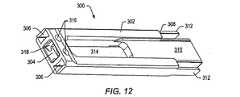
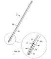
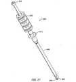
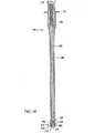
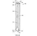
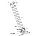
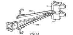
脊柱インプラント挿入処置用の器具セットは、様々な挿入器具を備えてもよい。挿入器具は、スプレッダ、セパレータ、ストラットシータを含んでもよいが、それらに限定されない。器具セットは、脊柱インプラント構成要素を含んでもよい。インプラント構成要素は、様々なサイズおよび前湾アラインメントのインプラント部材や、様々なサイズのコネクタを含むことができるが、それらに限定されない。スプレッダは、脊柱インプラントを形成するインプラント部材が、2つの隣接する椎骨の間に配置されることを可能にする。セパレータは、インプラント部材の間の所望の分離距離を確立するために、インプラント部材の間に配置されることができる。ある実施形態では、コネクタまたはコネクタ群が、セパレータを通ってインプラント部材内へ挿入される。コネクタは、インプラント部材を互いに結合する。 The instrument set for the spinal implant insertion procedure may comprise various insertion instruments. The insertion instrument may include, but is not limited to, a spreader, separator, and strut theta. The instrument set may include a spinal column implant component. Implant components can include, but are not limited to, implant members of various sizes and anterior bay alignment and connectors of various sizes. The spreader allows the implant member forming the spinal column implant to be placed between two adjacent vertebrae. A separator can be placed between the implant members to establish a desired separation distance between the implant members. In certain embodiments, a connector or group of connectors is inserted through the separator and into the implant member. The connector couples the implant members together.
スプレッダは、インプラント部材を、椎骨の間の準備された椎間腔内に配置されることを可能にする。スプレッダは、患者の切り口の上方から椎間腔内のスプレッダの遠端部の容易な配置を許すように、十分長くてもよい。スプレッダは、脊柱インプラントのインプラント部材をスプレッダと固定するホルダを備えてもよい。ホルダおよび取り付けられたインプラント部材は、前方の脊柱インプラントの挿入処置中に、椎間腔内に配置されてもよい。ホルダ間の距離は、スプレッダ内へセパレータを挿入することによって調節されてもよい。セパレータは、椎骨の過度の伸延なしに、インプラント部材の外側表面間の所望の分離距離を確立してもよい。 The spreader allows the implant member to be placed in a prepared disc space between the vertebrae. The spreader may be long enough to allow easy placement of the distal end of the spreader within the intervertebral space from above the patient's incision. The spreader may comprise a holder that secures the implant member of the spinal column implant to the spreader. The holder and attached implant member may be placed in the intervertebral space during the anterior spinal implant insertion procedure. The distance between the holders may be adjusted by inserting a separator into the spreader. The separator may establish a desired separation distance between the outer surfaces of the implant member without excessive distraction of the vertebrae.
1対のインプラント部材の間の所望の分離距離を確立することのほかに、セパレータは、コネクタをインプラント部材に導く通路を備えてもよい。コネクタは、インプラント部材の間の分離距離を固定してもよい。脊柱インプラントのある実施形態では、インプラント部材は、スロットを備えてもよい。コネクタの部分は、インプラント部材を互いに接合するためにスロット内に配置されてもよい。 In addition to establishing a desired separation distance between a pair of implant members, the separator may include a passage that guides the connector to the implant member. The connector may fix the separation distance between the implant members. In certain embodiments of spinal implants, the implant member may comprise a slot. Portions of the connector may be disposed in the slots for joining the implant members together.
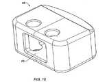
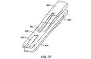
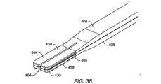
スプレッダの一実施形態は、インプラントホルダを有してもよい。インプラント部材の開口または開口群は、インプラントホルダ上に圧入してもよい。ロッキングピンが、スプレッダをインプラント部材に固定するため、およびスプレッダスロットのインプラント部材スロットに対する適切なアラインメントを維持するために、スプレッダのスロット内およびインプラント部材スロット内に挿入されてもよい。代替となる実施形態では、スプレッダは、インプラント部材の蟻継ぎチャネル内に挿入されているインプラントホルダを有してもよい。スプレッダが蟻継ぎチャネル内に完全に挿入されたとき、インプラント部材スロットは、スプレッダ内のスロットと位置合わせされる。スプレッダが蟻継ぎチャネル内に挿入されるとき、インプラントホルダ内の隙間が圧縮されてもよい。隙間の圧縮に対抗するためにアームによって及ぼされる力が、スプレッダ上にインプラント部材を保持してもよい。別法として、インプラントホルダは、インプラント部材内の開口に嵌入するばね部材を有し、インプラント部材をスプレッダ上に保持するために蟻継ぎチャネルに力を及ぼしてもよい。 One embodiment of the spreader may have an implant holder. The opening or group of openings in the implant member may be press fit onto the implant holder. A locking pin may be inserted in the spreader slot and in the implant member slot to secure the spreader to the implant member and to maintain proper alignment of the spreader slot to the implant member slot. In an alternative embodiment, the spreader may have an implant holder that is inserted into the dovetail channel of the implant member. When the spreader is fully inserted into the dovetail channel, the implant member slot is aligned with the slot in the spreader. When the spreader is inserted into the dovetail channel, the gap in the implant holder may be compressed. The force exerted by the arm to counter the compression of the gap may hold the implant member on the spreader. Alternatively, the implant holder may have a spring member that fits into an opening in the implant member and exerts a force on the dovetail channel to hold the implant member on the spreader.
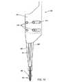
いくつかのインプラント挿入処置中、椎間腔は、挿入中にインプラント部材の突起が隣接する椎骨の表面を擦過することなく、スプレッダと結合されたインプラント部材の挿入を可能にするためには小さすぎてもよい。いくつかの実施形態では、脊柱インプラントによって確立される所望の分離距離よりも小さい距離にまで椎骨を分離するために、ディストラクタが使用されてもよい。その場合、椎間腔内に脊柱インプラントが形成されることができる。 During some implant insertion procedures, the intervertebral space is too small to allow the insertion of the implant member associated with the spreader without the protrusion of the implant member rubbing the surface of the adjacent vertebra during insertion. May be. In some embodiments, a distractor may be used to separate the vertebrae to a distance that is less than the desired separation distance established by the spinal column implant. In that case, a spinal column implant can be formed in the intervertebral space.
他の実施形態では、挿入ガイドが、インプラント部材の挿入を可能にするためには小さすぎる椎間腔内に配置されてもよい。挿入ガイドは、椎間腔への挿入深さを制限する止め部を備えてもよい。挿入ガイドを椎間腔内に配置した後、取り付けられたインプラント部材を備えるスプレッダが、挿入ガイドの間の椎間腔内に挿入されてもよい。挿入ガイドが、インプラント部材およびスプレッダの挿入後に取り外されてもよい。 In other embodiments, the insertion guide may be placed in an intervertebral space that is too small to allow insertion of the implant member. The insertion guide may include a stop that limits the depth of insertion into the intervertebral space. After placing the insertion guide in the intervertebral space, a spreader with an attached implant member may be inserted into the intervertebral space between the insertion guides. The insertion guide may be removed after insertion of the implant member and spreader.
スプレッダ内にセパレータを挿入して、椎骨にインプラント部材の外表面を押圧してもよい。スプレッダ内へセパレータを連続的に挿入することによって、インプラント部材の突起を椎骨内へ動かしてもよい。セパレータが、マレットまたはスラップハンマを使用してスプレッダ内へ打ち込まれてもよい。セパレータが、椎骨の間の所望の分離距離を確立することができる。 A separator may be inserted into the spreader to press the outer surface of the implant member against the vertebra. By continuously inserting the separator into the spreader, the process of the implant member may be moved into the vertebra. The separator may be driven into the spreader using a mallet or slap hammer. A separator can establish a desired separation distance between vertebrae.
セパレータをスプレッダ内へ挿入することによって椎骨間の分離距離を確立した後、コネクタが、インプラント部材を互いに接合するために、インプラント部材スロット内に配置されてもよい。コネクタのインプラント部材への挿入後、スプレッダおよびセパレータが椎骨の間から取り外されてもよい。 After establishing the separation distance between the vertebrae by inserting a separator into the spreader, a connector may be placed in the implant member slot to join the implant members together. After insertion of the connector into the implant member, the spreader and separator may be removed from between the vertebrae.
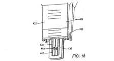
コネクタシータは、インプラント部材と、またはコネクタもしくはコネクタ群と結合されてもよい。コネクタシータは、コネクタまたはコネクタ群をインプラント部材に固定するために、インプラント部材およびコネクタまたはコネクタ群に力を及ぼしてもよい。コネクタシータによってインプラント部材およびコネクタに及ぼされる力は、コネクタをインプラント部材に固定するために、インプラント部材スロットおよび/またはコネクタの一部を変形させるのに十分であってもよい。コネクタシータは、いつ十分な量の力がコネクタおよびインプラント部材に及ぼされたかを表示するためのインジケータを備えてもよい。コネクタがインプラント部材に固定された後、コネクタシータが患者の開口から取り外されてもよい。開口が閉鎖される前に、骨成長材料が、インプラント部材の間の空間内に配置されてもよい。 The connector theta may be coupled to the implant member or to the connector or group of connectors. The connector theta may exert a force on the implant member and the connector or connector group to secure the connector or connector group to the implant member. The force exerted on the implant member and connector by the connector theta may be sufficient to deform a portion of the implant member slot and / or connector to secure the connector to the implant member. The connector theta may include an indicator for indicating when a sufficient amount of force has been exerted on the connector and the implant member. After the connector is secured to the implant member, the connector theta may be removed from the patient's opening. Bone growth material may be placed in the space between the implant members before the opening is closed.
インプラント部材が、インプラント部材の間に配置された骨成長材料に圧縮荷重を及ぼすように、コネクタが、インプラント部材を分離する距離の軽微な調整を可能にしてもよい。大きな圧縮力がインプラント部材に及ぼされた場合、コネクタおよびインプラント部材が、インプラント部材の大きな表面領域にわたって力を分散させる単一ユニットとして働いてもよい。 The connector may allow minor adjustment of the distance separating the implant members such that the implant members exert a compressive load on the bone growth material disposed between the implant members. When a large compressive force is exerted on the implant member, the connector and the implant member may act as a single unit that distributes the force over a large surface area of the implant member.
本発明の利点は、以下の詳細な実施形態の説明によって、および添付の図面を参照すれば当業者に明らかになるであろう。 The advantages of the present invention will become apparent to those skilled in the art from the following detailed description of the embodiments and with reference to the accompanying drawings.
本発明は、様々な修正および代替形態が可能であるが、その特定の実施形態を図中で一例として示し、本明細書で詳細に説明する。図面は一定の縮尺でないかもしれない。しかし、図面および詳細な説明は、本発明を開示された特定の形態に制限するように意図されておらず、逆に、本発明は、特許請求の範囲によって規定したような本発明の精神および範囲内にあるすべての修正、等価なもの、および代替形態を網羅していることを理解されたい。 While the invention is susceptible to various modifications and alternative forms, specific embodiments thereof are shown by way of example in the drawings and are described in detail herein. The drawings may not be to scale. However, the drawings and detailed description are not intended to limit the invention to the particular form disclosed, but on the contrary, the invention is not limited to the spirit and scope of the invention as defined by the claims. It should be understood that all modifications, equivalents, and alternatives that are within the scope are covered.
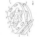
図面を参照すると、図1および図2は、インプラント10の実施形態の斜視図を示している。インプラントは、部材と、部材間のスペーサとを備える。部材は、インプラントによって互いに接合される骨の表面と接触するインプラント部材である。スペーサは、部材間の所望の距離を確立することができる。スペーサは、1つまたは複数の構成要素で形成されることができる。いくつかの実施形態では、インプラント10は脊柱インプラントである。いくつかの実施形態では、脊柱インプラントは、椎骨を互いに融着させるために、椎骨間の骨成長を促進する融着装置である。いくつかの実施形態では、脊柱インプラントは、椎骨の互いに対する少なくとも多少の運動を許しながら、2つの椎骨を互いに接合する人工椎間板である。いくつかの実施形態では、インプラントは、骨(たとえば大腿骨)の2つの部分を接合し、その融着を促進するインプラントでありえる。 Referring to the drawings, FIGS. 1 and 2 show perspective views of an embodiment of an
インプラント10は、1対のインプラント部材12と、インプラント部材を互いに結合するコネクタまたはコネクタ群14とを備える。インプラント10の実施形態では、インプラント部材12は1対の係合プレートであり、コネクタ14はストラットである。 The
図3は、隣接する椎骨18間の椎間腔16を示す。椎間腔16を形成する椎間板切除術中、椎間板20の一部または全部が、隣接する椎骨18間で除去される。 FIG. 3 shows the
図4は、椎間板20内に形成された椎間腔16に挿入されたインプラント10の実施形態を示している。インプラント10は、脊柱の安定化を提供し、隣接する椎骨18を互いに融着させる骨成長を促進することができる。 FIG. 4 shows an embodiment of the
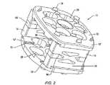
図5は、インプラント部材の内部表面を強調しているインプラント部材12の実施形態を示している。図6および図7は、コネクタ14の実施形態を示している。インプラント部材およびコネクタは、チタニウム、チタニウム合金、ステンレス鋼、セラミック材料、骨、ポリマー、またはそれらの組合せを含むがそれらに限定されない、いかなる生体適合性の材料製であってもよい。ある実施形態では、インプラント部材は、Ti6Al4V−Eliなどのチタニウムとアルミニウムの合金で形成されている。脊柱挿入処置用の器具セットは、いくつかの異なるサイズのインプラント部材を備える。器具セットに含まれる対のインプラント部材が有する。 FIG. 5 shows an embodiment of the
器具セットは、インプラント部材を備えることができる。患者体内に挿入されたとき、骨と接触または隣接する異なる表面積を有するインプラント部材が、器具セット内に設けられている。たとえば、器具セットは、大きな、中間の、および/または小さなサイズのインプラント部材を備えることができる。患者体内に挿入されたとき、骨と接触または隣接することになる大きなインプラント部材の表面積は、中間のインプラント部材の同様の表面積よりも大きく、中間のインプラント部材の同様の表面積は、小さなインプラント部材の同様の表面積よりも大きい。外科医は、インプラント挿入処置の前またはその間に、どのサイズのインプラント部材を使用するかを決定することができる。1対の同じサイズのインプラント部材が、患者体内で形成されるインプラントの一部を形成することができる。 The instrument set can comprise an implant member. An implant member having a different surface area in contact with or adjacent to the bone when inserted into the patient is provided in the instrument set. For example, the instrument set can comprise large, intermediate, and / or small sized implant members. When inserted into a patient, the surface area of the large implant member that will contact or be adjacent to the bone is greater than the similar surface area of the intermediate implant member, and the similar surface area of the intermediate implant member is that of the small implant member. Greater than similar surface area. The surgeon can determine which size implant member to use before or during the implant insertion procedure. A pair of equally sized implant members can form part of an implant formed within a patient.
インプラント部材12の外部表面22(図1および図2に示す)は、チタニウムプラズマ溶射、骨形態形成蛋白質、および/またはヒドロキシアパタイトなどであるがそれらに限定されない、被覆または外側層を備えることができる。被覆は骨一体化を促進することができる。骨一体化とは、物体を骨に付着させる接続骨の形成をもたらす治療プロセスのことを呼ぶ。物体は、インプラントまたはインプラントの一部でありえる。 The outer surface 22 (shown in FIGS. 1 and 2) of the
外部表面22を被覆することに加えて、またはその代わりに、外部表面が、インプラント部材の隣接する椎骨との骨一体化を促進するために粗面処理されてもよい。インプラント部材12の外部表面22は、化学エッチング、表面研磨、ショットピーニング、放電プロセスの使用、または表面内への粒子埋込みなどを含むがそれらに限定されない、いくつかの処理技術のいずれかによって粗面処理されることができる。 In addition to or instead of coating the
インプラント部材12の外部表面22は、インプラント部材12と隣接する椎骨との間に大きな接触領域があるように大きな表面積を有することができる。大きな接触領域は、インプラント10が接触する椎骨の陥没および/または変形を最小化する。 The
図1および図2に示すように、インプラント部材12は、外部表面22上に複数の突起24を備えることができる。形成されたインプラント10の突起24は、インプラントを隣接する椎骨に確実に固定するために隣接する椎骨内へ延びることができる。ある実施形態では、突起24は、それぞれ6個の突起を含む2つの径方向の列で配置されている。それよりも少ないまたは多い突起を備える他の構成も、使用することができる。突起24は、インプラント部材12の外部表面22から約0.2mmまたはそれ以上延びることができる。ある実施形態では、突起24は、外部表面22から約1mm延びている。突起24は、インプラント部材を椎骨の表面に碇着することができる。インプラント部材12の外部表面22は、曲率を備えることができる。曲率は、インプラント部材12の外部表面22を、椎骨表面の形状に実質上一致させることを可能にする。たとえば、インプラント部材の外部表面22は、椎骨の解剖学的なドームと一致する。 As shown in FIGS. 1 and 2, the
インプラント部材12の実施形態は、傾斜した外部表面22を備えることができる。傾斜した外部表面は、組み立てられたインプラント10の前方高さが、インプラントの後方高さと異なることを可能にする。異なる傾斜した外部表面22を有するインプラント部材12のいくつかの異なる対が、患者にインプラント挿入処置を行う外科医チームに提供される器具セットに備えられることができる。異なる傾斜のインプラント部材12の使用可能性は、外科医が、患者に対して適切な前湾アラインメントを提供するインプラント10を形成することを可能にする。器具セットのある実施形態では、器具セットに設けられているインプラント部材12は、約3°の増分での約0°から約9°の範囲の傾斜を有する。このことは、外科医が、約0°(各インプラント部材が0°の前湾角を有する)から、約18°(各インプラント部材が9°の前湾角を有する)の前湾調整を有するインプラント10を形成することを可能にする。いくつかの実施形態では、異なる量の前湾角を有するインプラント部材が、所望の量の前湾調整を提供するために使用されることができる。たとえば、約9°の前湾調整が、9°の前湾角を有するインプラント部材と、0°の前湾角を有する第2のインプラント部材とを使用してインプラントを形成することによって得られることができる。また9°の前湾調整は、6°の前湾角を有するインプラント部材と、3°の前湾角を有するインプラント部材を使用してインプラントを形成することによって得られる。インプラント10の代替となる実施形態では、コネクタまたはコネクタ群14が、前湾調整を提供するために傾斜した表面を備えることができる。他の実施形態では、他の傾斜の範囲および増分のインプラント部材および/またはコネクタが提供されることができる。 Embodiments of the
インプラント部材は、色分けされているおよび/または指標を備えることができる。色分けおよび/または指標は、特定のインプラント部材のサイズを表示することができる。たとえば、インプラント部材が中サイズのインプラント部材であることを表示するために、インプラント部材が、文字「M」で刻印されることができる。同様に、インプラント部材が有する前湾角の量を示すために、インプラント部材が、色分けされているおよび/または指標を備えることができる。 The implant member can be color coded and / or provided with an indicator. Color coding and / or indicators can indicate the size of a particular implant member. For example, the implant member can be imprinted with the letter “M” to indicate that the implant member is a medium size implant member. Similarly, the implant member can be color coded and / or provided with an indicator to indicate the amount of anterior bay angle that the implant member has.
インプラント10が、図4に示すように隣接する椎骨18の間に配置されるとき、骨成長材料26が、コネクタまたはコネクタ群14によって結合された2つのインプラント部材12の間に包まれることができる。骨成長材料26は、自家移植骨片骨(患者の腸骨稜からの骨など)、同種移植骨、合成骨成長材料、またはそれらの組合せであってよいが、それらに限定されない。 When the
図1、図2、および図5に示すように、インプラント部材12は、複数の開口28を備えることができる。上側インプラント部材12’内の開口28は、インプラントが椎間腔内に形成されるとき、インプラント10の下側インプラント部材12”内の開口と鉛直方向に位置合わせされることができる。骨が、椎骨を互いに融着させるために開口28を通って進展されることができる。骨移植片は、隣接する椎骨の融着を促進する。いくつかの開口28は、図1に示すように、くぼんだ表面30を有することができる。 As shown in FIGS. 1, 2, and 5, the
図5は、部材の内部表面を強調したインプラント部材12の斜視図を示している。各インプラント部材12は、テーパ付きスロット32を備えることができる。スロット32は、インプラント部材12の最も幅広の近位の前方側面34であることができる。スロット32の側壁36は、傾斜している、または蟻継ぎ状であることができ、したがってスロットは、インプラント部材12の内部表面よりもその底面で幅広である。 FIG. 5 shows a perspective view of the
図5に示すように、インプラント部材12もまたくぼんだ表面38を備えることができる。くぼんだ表面38は、インプラント部材12の前方側面34で始まり、インプラント部材の後方側面40に到達する前に終わることができる。ある実施形態では、くぼんだ表面38の側壁は、実質上直線状である。他の実施形態では、くぼんだ表面38の側壁は、インプラント部材12を挿入ツールと結合するように、蟻継ぎ状である、または他の適切な形状であることができる。 As shown in FIG. 5, the
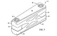
図6および図7は、コネクタ14の実施形態を示している。コネクタ14はストラットである。コネクタ14は、テーパ付きの端部表面42および傾斜した側部部分44を有することができる。コネクタ14のテーパ付きの端部表面42は、インプラント部材のテーパつきのスロット内に配置されることができる。テーパ付きの端部表面42のテーパは、インプラント部材スロット32(図5に示す)のテーパと実質上対応することができ、したがってインプラント部材とインプラント部材内に挿入されたコネクタとの間に大きな接触領域がある。側面44の角度は、インプラント部材内のテーパ付きスロット側面の角度に対応することができる。インプラント部材のスロットのテーパ付き形状およびコネクタ14のテーパ付きの端部表面42は、コネクタのスロット内への挿入と逆の方式でのインプラント部材からのコネクタの取外ししか許さない。コネクタをインプラント部材に固定しようと望むとき、コネクタの取外しを防止するように、テーパ付きスロットおよび/またはコネクタを変形させるために、大きな力が、コネクタおよびインプラント部材に及ぼされることができる。 6 and 7 show an embodiment of the
摩擦接続が、コネクタがインプラント部材のスロット内に完全に挿入されたとき、大きな接触領域にわたってコネクタ14とインプラント部材との間に形成されることができる。別の実施形態では、コネクタ14が、摩擦係合ではない手段によってインプラント部材に取り付けられることができる。たとえば、締まり嵌めが、コネクタとインプラント部材との間に形成されることができる。インプラント部材内でコネクタを保持するチャネルは、コネクタがインプラント部材のチャネル内に完全に挿入されたとき、締まり嵌めを形成するためにコネクタ内のくぼみ内に嵌入する突起を備えることができる。別法として、インプラント部材内でコネクタ14を保持するチャネルは、コネクタがインプラント部材のチャネル内に完全に挿入されたとき、コネクタから延びる突起と締まり嵌めを形成するくぼみを備えることができる。コネクタ14をインプラント部材のチャネル内に完全に挿入するために必要な力の量は、インプラント部材へのコネクタの意図されない完全な挿入を阻止することができる。締まり嵌めは、コネクタがインプラント部材内に完全に挿入されたとき、インプラント部材からのコネクタ14の取外しを阻止することができる。 A friction connection can be formed between the
図6に示すコネクタの実施形態などのコネクタ14の実施形態は、第1の部材46と、第2の部材48と、ピン50とを備えることができる。組み立てられたコネクタ14は、止めねじ52によって互いに保持されることができる。組み立てられたコネクタ14は、インプラント部材の間に配置されることができる。コネクタ14は、様々なサイズでの脊柱挿入処置を行うための器具セットに提供されることができる。たとえば、器具セットは、中間の大きさおよび大きなインプラント部材のためのコネクタを備えることができる。器具セットは、約2mmの増分での約8mmから約16mmの範囲のインプラント部材間の分離距離を有するインプラントを形成するコネクタを備えることができる。他のサイズ範囲および/またはサイズ増分のコネクタ14も提供することができる。 Embodiments of the
ピン50が、第1の部材46を第2の部材48に対して保持することができる。止めねじ52が、ピン50と接触してピンに力を及ぼすことができる。力は、第1の部材46および第2の部材48からのピン50の取外しを阻止することができる。第1の部材46は、第2の部材48の周りに回転することができる。コネクタ14内のピンタイプの接続部は、異なるサイズのコネクタがインプラント部材内に挿入されることを可能にする。結果としてのインプラントは、形成されたインプラントの中間および横方向端部で異なる高さを有することができる。他の実施形態では、インプラント部材は、結果としてのインプラントがインプラントの中間および横方向端部で異なる高さを有するように、異なる中間および横方向の高さを有して形成されることができるが、インプラントを形成するために使用される各コネクタは、実質上同じ高さを有する。 A
患者体内でのインプラントの形成後、インプラントのインプラント部材に圧縮力が及ぼされることができる。インプラント部材に及ぼされた圧縮力は、コネクタ14のピン50をそらせ、インプラントの第1のインプラント部材が、インプラントの第2のインプラント部材の方へ小さな距離移動することを許す。したがって、インプラント部材に及ぼされた圧縮力がいくらか、インプラント部材の間に配置された骨成長材料に伝達されることがある。骨成長材料への応力の付加が、インプラントによって接合された椎骨を互いに融着させる骨の形成を促進することができる。骨は、通常の密度を維持するために応力を受けることを必要とする。骨の強度および健康は、その密度に直接関係する。骨は、応力を受けない、または応力から遮蔽されているとき、密度を失い体内に吸収されることがある。 After formation of the implant within the patient, a compressive force can be exerted on the implant member of the implant. The compressive force exerted on the implant member deflects the
脊柱が通常曝されている力を超えるインプラントへの圧縮力の付加は、図6に示すコネクタ部材46、48、およびピン50を、単一の中実部材として働かせることができる。単一の中実部材は、インプラント部材が、所定の間隔よりも近くなるように互いに向かって圧縮されることを許さないことができる。椎骨に及ぼされる過度の力は、インプラントに隣接する骨の破壊を生じさせることがある。インプラントと椎骨との間の大きな接触表面は、骨の破壊が阻止されるように、大きな椎骨領域にわたる大きな力の散逸を促進することができる。骨成長材料への大きな力の繰り返しの付加は、接続骨の形成を阻止し、繊維塊の形成を促進することができる。インプラント部材の互いに向かう運動を制限することは、インプラント部材の間に配置された骨成長材料への過度の力の付加を阻止することができる。 The application of compressive force to the implant beyond the force to which the spinal column is normally exposed can cause the
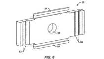
図7は、代替となるコネクタ実施形態を示している。コネクタ14は、可撓性の部材54と、リミッタ56と、ピン58とを備えることができる。ピン58は、リミッタ56を可撓性の部材54と結合することができる。ピン58は、圧入、ねじ付け、溶接、接着、またはその他の方法で可撓性の部材54に取り付けられることができる。形成されたインプラントのインプラント部材に及ぼされる圧縮力は、可撓性の部材54を圧縮することができ、力のいくらかが、インプラント部材の間に配置された骨成長材料によって共有されることを許す。リミッタ56は、コネクタ14の可撓性の部材54が、所定の間隔よりも近くなるように互いに向かって圧縮されることを許さないようなサイズにされている。 FIG. 7 shows an alternative connector embodiment. The
コネクタ14およびインプラントのリミッタ56は、インプラント内に配置された骨成長材料に及ぼされるひずみの量を選択的に制御することができる。たとえば、コネクタ14は、インプラント内の骨成長材料上の全ひずみを、インプラント部材に及ぼされるひずみの約0.5%未満に制限することができる。たとえばインプラント部材に及ぼされるひずみの約1%よりも大きい、骨成長材料への過度のひずみは、骨形成材料に骨の代わりに繊維塊を形成させることがある。コネクタ14は、医療用等級チタニウムなどの比較的剛性の材料製である。コネクタ14は、骨形成材料を遮蔽し、インプラント部材に及ぼされるひずみの大部分(99%以上)を支持することができるが、なお骨形成材料に及ぼされるいくらかのひずみが、骨の形成を促進することを許す。
ブランクから形成されるコネクタが所望の可撓性特性を有するように、材料の一部が、コネクタブランクから所望のパターンで除去されることができる。ブランクの端部は、端部がインプラント部材と結合するように形成されることができる。図7は、可撓性部材54の圧縮を可能にする「X」型のパターンを有するコネクタ14の実施形態を示している。他のパターンが使用されてもよい。コネクタのパターン内の開口は、コネクタが組み立てられたインプラントの一部を形成するとき、骨移植片が開口を通過するのを阻止するのに十分に小さいことが可能である。可撓性の部材54は、フライス加工、穿孔、レーザー切削、放電加工、および/またはマスキングおよびエッチングを含むがそれらに限定されない様々な方法を使用して形成されることができる。 A portion of the material can be removed from the connector blank in a desired pattern so that the connector formed from the blank has the desired flexibility characteristics. The end of the blank can be formed such that the end joins with the implant member. FIG. 7 illustrates an embodiment of the
コネクタ14およびインプラント部材は、インプラント部材と椎骨との間の大きな接触領域全体を通じて椎骨に及ぼされる大きな力を分配することによって、隣接する椎骨の破壊を阻止するように互いに機能することができる。 The
図1および図2に示すように、コネクタ14は、コネクタがインプラント部材のテーパ付きスロット32内に挿入されたとき、インプラント部材12の外側表面22の間の分離距離を確立することができる。インプラント部材12間の様々な分離距離を確立する複数のコネクタ14が、インプラント挿入処置を行う外科医チームに提供される器具セット内に備えられてもよい。いくつかの異なるコネクタサイズの使用可能性は、隣接する椎骨間で所望の分離距離を確立する患者体内でのインプラント10の形成を許すことができる。 As shown in FIGS. 1 and 2, the
器具セットの実施形態には、約2mmの増分で約8mmから約26mmの範囲の外側表面22の間の最大の分離距離を有するインプラント10を形成することが可能であるコネクタ14が、設けられることができる。インプラント部材12の間に適切なサイズのコネクタ14を挿入することは、適切にサイズ合わせされたインプラント10を形成することができる。コネクタ14は、色付けされている、および/またはコネクタによって形成されるインプラント10のサイズについて使用者に情報を与える数字の指標を備えることができる。たとえば、インプラント部材12の外側表面22の間の約12mmの最大の分離を有するインプラント10を形成するコネクタ14は、青色であり、および/またはコネクタの一部の上にエッチング、印刷、または刻印された「12」を備えることができる。同様に、インプラント部材12の外側表面22の間の約14mmの最大の分離を有するインプラント10を形成するコネクタ14は、緑色であり、および/またはコネクタの一部の上にエッチング、印刷、または刻印された「14」を備えることができる。コネクタ14もまた、コネクタがそれとともに使用されるインプラント部材12のサイズを表示する指標を備えることができる。たとえば、コネクタ14は、小さい、中間の、または大きなインプラント部材12とともに使用されるコネクタを表示するために、コネクタの一部の上にエッチング、印刷、または刻印された「S」、「M」、または「L」を備えることができる。 An embodiment of the instrument set is provided with a
オプションの裏打ちプレートが、組み立てられたインプラントの後方側面に近接して配置されることができる。図8は、オプションの裏打ちプレート60の実施形態を示している。裏打ちプレート60は、ポリエチレン、ポリプロピレン、またはポリ塩化ビニルなどであるが、それらに限定されない生体適合性ポリマー製であることができる。別法として、裏打ちプレート60は、ポリアンヒドライド、アルファポリエステル、および/またはポリ乳酸ポリグリコール酸コポリマーなどであるが、それらに限定されない、生体吸収性および/または生体分解性ポリマー製であることができる。裏打ちプレート60は、くぼみ62を備える。くぼみ62は、単一サイズの裏打ちプレートが、異なるサイズのインプラント内に嵌合するように構成されることを可能にする。完全な裏打ちプレートは、大きなインプラント内に嵌入することができる。裏打ちプレート60の端部は、裏打ちプレートがより小さいインプラント内に嵌合するように、くぼみ62で切断される、または他の方法で分離されることができる。組み立てられたインプラントの裏打ちプレート60の挿入深さは、タブ64が、くぼんだ表面38の後方端部を画定するインプラント部材12の端部壁面66と接触するとき制限されることができる。インプラント部材12の端部壁面66は、図5に示されている。 An optional backing plate can be placed proximate to the posterior side of the assembled implant. FIG. 8 shows an embodiment of an optional backing plate 60. The backing plate 60 can be made of a biocompatible polymer such as, but not limited to, polyethylene, polypropylene, or polyvinyl chloride. Alternatively, the backing plate 60 may be made of a bioabsorbable and / or biodegradable polymer such as, but not limited to, polyanhydride, alpha polyester, and / or polylactic acid polyglycolic acid copolymer. it can. The backing plate 60 includes a
インプラント挿入処置中、図3に示すように、椎骨18の間に椎間腔16を形成するために椎間板20の一部を除去するために、椎間板切除術が行われることができる。椎間腔16内にインプラントが形成されることができる。椎間板20の残りの部分が脱漏されるとき、裏打ちプレートが使用されることができる。裏打ちプレート60(図8に示す)内の開口68は、挿入ロッドにねじ付けされる、またはその他の方法で解放可能に固定されることができる。挿入ロッドは、患者の開口の上方の位置からのインプラントのインプラント部材間の裏打ちプレート60の挿入および位置決めを可能にする。患者の開口の上方の位置からの裏打ちプレート60の挿入および位置決めが可能であることは、視認性および裏打ちプレートの組み立てられたインプラント内への挿入の容易さを促進することができる。挿入後、ロッドはねじを外される、またはその他の方法で裏打ちプレート60から除去されることができる。裏打ちプレート60は、インプラントからの骨成長材料の移動を阻止することができる。椎間板切除術後、椎間板の残りの部分が脱漏していないまたは飛び出していない場合、裏打ちプレート60は必要ない可能性がある。 During the implant insertion procedure, a discectomy can be performed to remove a portion of the
図9〜図55は、融着処置中に患者体内でインプラントを形成するために使用されることができる器具の実施形態を示している。インプラントの形成中に使用される器具は、幅および深さスペーサ100と、高さスペーサ200と、セパレータ300と、スプレッダ400と、ロッキングピン500と、エクステンダ600と、マレット650と、鉗子700と、深さゲージ800と、スラップハンマ900と、挿入ガイド1000とを備えることができるが、それらに限定されない。また、シータ1100およびリテーナ1300が、コネクタをインプラント部材に確実に固定するために使用されることができる。器具の様々な部品は、金属、セラミック、ポリマー、またはそれらの組合せで形成されてもよい。様々な器具の部品を形成するために使用される材料は、殺菌処置に耐えるように高い耐熱性および耐薬品性を有することができる。 9-55 illustrate an embodiment of an instrument that can be used to form an implant within a patient during a fusion procedure. The instruments used during the formation of the implant include width and
融着処置中に使用される器具が、器具セット内に設けられることができる。器具セットは、形成されるインプラントの構成要素を備えることができる。器具セットは、様々なタイプの骨鉗子、様々なタイプのキューレット、骨目打ち、綿球などの(それらに限定されない)他の器具を備えてもよい。 An instrument used during the fusion procedure can be provided in the instrument set. The instrument set can comprise the components of the implant to be formed. The instrument set may comprise other instruments such as but not limited to various types of bone forceps, various types of curettes, bone perforations, cotton balls.
図9は、幅および深さスペーサ100の実施形態を示している。幅および深さスペーサ100の端部102は、インプラント部材の前部表面のサイズに実質上対応する形状を有することができる。器具セットに含まれるインプラント部材のサイズに対応するサイズの幅および深さスペーサのサイズが、器具セット内に設けられることができる。たとえば、器具セットが中間のおよび大きなインプラント部材を備える場合、器具セットは、大きなインプラント部材に対応する端部を有する第1の幅および深さスペーサと、中間のインプラント部材に対応する端部を有する第2の幅および深さスペーサとを備えることができる。幅および深さスペーサの代替となる実施形態は、第1のサイズのインプラント部材に実質的に対応する第1の端部と、第2のサイズのインプラント部材に実質的に対応する第2の端部とを有することができる。端部102の外部表面は、端部の相対サイズを示すための指標を備えることができる。指標は、印刷、エッチング、またはその他の方法で端部に配置されることができる。 FIG. 9 shows an embodiment of a width and
隣接する椎骨間の椎間腔の形成中、椎間板の一部が除去されることができる。幅および深さスペーサ100は、放射線画像とともに、特定のサイズのインプラント部材に対する開口の適切な幅および深さを決定するために使用されることができる。同様に、幅および深さスペーサが、インプラントによって互いに融着される骨セグメントの間の開口の形成中に使用されることができる。 During formation of the intervertebral space between adjacent vertebrae, a portion of the intervertebral disc can be removed. The width and
椎間腔または骨セグメント間の開口の形成後、形成されるインプラントのサイズを決定するために、高さスペーサが使用されることができる。図10は、高さスペーサ200の実施形態を示している。外科医は、高さスペーサ200をスラップハンマに取り付けることができる。外科医は、スラップハンマの端部をアタッチメントマウント202内に配置し、椎間板切除術によって形成された準備された空間の上部に高さスペーサを配置することができる。外科医は、スラップハンマのスライドを下側止め部に打ち付けることによって及ぼされる力によって、高さスペーサ200を挿入することができる。高さスペーサ200が、スラップハンマによる1回または2回の打ち込みで、またはスラップハンマによる打ち込みなしで、椎間腔内に容易に嵌入した場合、高さスペーサは小さすぎることがある。より大きな高さスペーサが、スラップハンマに取り付けられ、準備された椎間腔内に挿入されることができる。高さスペーサ200が、スラップハンマによる力で椎間腔内に嵌入しない場合、高さスペーサは大きすぎることがある。より小さな高さスペーサが、スラップハンマに取り付けられ、準備された椎間腔内に挿入されることができる。高さスペーサ200が、スラップハンマによる3回または4回の打ち込みで、椎間腔内に嵌入した場合、高さスペーサは適切なサイズのインプラントに対応していることがある。高さスペーサ200の椎間腔内への挿入後、スペーサは、スラップハンマのスライドを上側止め部に打ち込むことによって、椎間腔から取り外されることができる。いくつかの挿入処置中、エクステンダ(図21に示すエクステンダ600など)およびマレットが、高さスペーサを椎間腔内に挿入するために使用されることができる。 After formation of the opening between the intervertebral space or bone segment, a height spacer can be used to determine the size of the implant to be formed. FIG. 10 shows an embodiment of the
図11および12は、セパレータの実施形態の斜視図を示している。セパレータ300は、本体302と、アタッチメントマウント304と、通路306と、止め表面308と、トング310と、アーム312とを備えることができる。本体302は、セパレータ300の重量を低減させる中央開口314を備えることができる。アタッチメントマウント304は、セパレータ300が、スラップハンマなどの駆動装置と結合することを可能にする。セパレータ300の上側部分を通る孔316が、図27に示すスラップハンマ900の戻り止め902などの挿入/取外し器具の戻り止めと係合する接触表面318を画定することができる。本体302を通る通路306は、コネクタおよびロッキングピン500(図20に示す)が、セパレータ300を通過することを可能にするようなサイズにされていることができる。止め表面308が、セパレータ300のスプレッダ内への挿入深さを制限することができる。セパレータ300のトング310およびアーム312が、図14に示すスプレッダ400の実施形態などのスプレッダと結合されるインプラント部材の間の分離距離を確立することができる。セパレータ300によってもたらされた分離は、隣接する椎骨を過度に伸延させることなく、椎間腔内でのインプラントの形成を可能にする。トング310は、セパレータ300のスプレッダ内への挿入を容易にするスプレッダ接触表面320を備えることができる。表面320は、スプレッダ内へのセパレータ300の挿入を容易にするように、面取り、丸み付け、またはその他の方法で機械加工されることができる。アーム312は、インプラント挿入処置中、スプレッダに対するセパレータ300の回転運動を阻止することができる。 11 and 12 show perspective views of an embodiment of the separator.
セパレータは、スプレッダに結合された1対のインプラント部材の間の分離距離を確立することができる。コネクタまたはコネクタ群が、セパレータが適切な分離距離を確立した後、インプラント部材を互いに結合することができる。セパレータは、コネクタまたはコネクタ群をインプラント部材間の適切な位置に方向付ける、溝またはその他のタイプのガイドを備えることができる。いくつかのセパレータ実施形態は、コネクタをインプラント部材間の適切な位置にガイドするためのセパレータを通るコネクタ通路を備えないことができる。いくつかの実施形態では、コネクタまたはコネクタ群が、セパレータと相互作用することなくインプラント部材間に挿入されることができる。たとえば、コネクタが、鉗子に取り付けられることができる。コネクタは、鉗子から解放される前にインプラント部材間に適切に配置されることができる。 The separator can establish a separation distance between a pair of implant members coupled to the spreader. A connector or group of connectors can couple the implant members together after the separator has established an appropriate separation distance. The separator can comprise a groove or other type of guide that directs the connector or group of connectors to the appropriate location between the implant members. Some separator embodiments may not include a connector passage through the separator to guide the connector to the proper position between the implant members. In some embodiments, a connector or group of connectors can be inserted between implant members without interacting with the separator. For example, a connector can be attached to the forceps. The connector can be properly positioned between the implant members before being released from the forceps.
スプレッダが、椎骨などの隣接する骨構造の間にインプラント部材を配置し、適切な伸延を達成することを援助するために使用されてもよい。セパレータが、椎骨と骨セグメントとの間に所望の分離距離を確立するために、スプレッダ内に挿入されてもよい。 A spreader may be used to place the implant member between adjacent bone structures, such as vertebrae, to help achieve proper distraction. A separator may be inserted into the spreader to establish a desired separation distance between the vertebra and the bone segment.
図13は、スプレッダ400の実施形態の斜視図である。スプレッダ400は、ハンドル402と、拡張部分404と、本体406と、部材ホルダ408とを備えることができる。図14に示すように、スプレッダ400はまた、ばね部材410を備えることができる。図13は、セパレータが部材ホルダ間に配置されているかのように、部材ホルダ408が散開した位置にあるスプレッダ実施形態を示している。図14は、部材ホルダ408が、部材ホルダ間へのセパレータの挿入前の初期位置にあるスプレッダ実施形態を示している。 FIG. 13 is a perspective view of an embodiment of the
ハンドル402は、部材ホルダ408が椎間腔内の所望の位置に配置されることを可能にすることができる容易に把持可能な部材であることができる。拡張部分404は、融着処置中、部材ホルダが椎骨または骨セグメントの間に配置されたとき、ハンドル402が患者から延びるように十分な長さを有するスプレッダを実現することができる。本体406は、部材ホルダが互いに対して横方向に移動することを許す。 The
図13および図14に示した実施形態などのいくつかの実施形態では、ハンドル402は、スプレッダ400の本体406の一体部品であることができ、部材ホルダ408は、本体に取り付けられることができる。「一体部品」とは、一部片の材料から、または別個の部片の互いに対する軸方向または回転運動を阻止するために互いに付着された別個の部片から形成された部品のことを称する。 In some embodiments, such as the embodiment shown in FIGS. 13 and 14, the
代替となる実施形態では、ハンドル402は、図15に示すように、延長部材404および部材ホルダ408’の一体部品であることができる。スプレッダ400の本体406は、図16に示すように、第2の部材ホルダ408”と結合されることができる。第1の部材ホルダ408’は、本体406の一体部品であることができる。 In an alternative embodiment, the
図13および図14に示すように、スプレッダ400の本体406は、1対のチャネル部材412を備えることができる。孔414およびスロット416の組が、チャネル部材412内に形成されることができる。孔414は、第1の部材ホルダ408’がスプレッダ400の本体406に一体に取り付けられることを可能にする。第1の部材ホルダ408’は、第1の部材ホルダが本体406の一体部品であるように、チャネル部材412の間のピン418によって取り付けられることができる。ピン418は、本体406の孔414を通って第1の部材ホルダ408’内に圧入されることができる。スロット416は、第2の部材ホルダ408”がチャネル部材412の間のピン418によって取り付けられることを可能にする。ピン418は、本体406のスロット416を通して第2の部材ホルダ408”内に圧入されることができる。スロット416は、第2の部材ホルダが本体に取り付けられたとき、第2の部材ホルダ408”が本体406および第1の部材ホルダ408’に対して運動することを可能にする。スロット416は、第2の部材ホルダ408”が第1の部材ホルダ408’に向かうようにまたは離れるように横方向に運動することを可能にする。第1の部材ホルダ408’および第2の部材ホルダ408”のスプレッダ400の遠端部および近端部に向かう軸方向運動は阻止される。 As shown in FIGS. 13 and 14, the
図16に示したスプレッダ実施形態で示すように、ピン418は、本体406内のスロット416を通って部材ホルダ408’内に圧入されることができる。ピン418は、第2の部材ホルダ408”を、第2の部材ホルダが第1の部材ホルダ408’に対して横方向に移動することができるように本体406に取り付けることができる。 As shown in the spreader embodiment shown in FIG. 16, the
チャネル部材412(図13、図14、および図16に示す)の内部表面の間の分離距離は、図11に示すセパレータ300などのセパレータの幅よりもわずかに大きいことができる。チャネル部材412間の分離距離は、スプレッダ400内に配置されたセパレータの横方向運動および回転運動を阻止することができる。チャネル部材412間の分離距離はまた、セパレータ300のコネクタ通路306と、スプレッダ400の部材ホルダ408と結合されたインプラント部材内のテーパ付きスロットとの適切な位置合わせを促進することができる。 The separation distance between the inner surfaces of the channel member 412 (shown in FIGS. 13, 14, and 16) can be slightly larger than the width of a separator, such as the
スプレッダ400は、図13および図14に示すように、深さインジケータ420を備えることができる。深さインジケータ420は、スプレッダ400のハンドル402および/または延長部分404内のスロット、ショルダ、延長部、くぼみ、および/または指標であることができるが、それらに限定されない。代替となる実施形態では、深さインジケータは、スプレッダ400の他の位置に配置されることができる。深さインジケータ420は、コネクタがインプラント部材内の所望の位置に挿入されたときを表示するために、図26に示す深さゲージ800などの深さゲージとともに使用されることができる。 The
いくつかのスプレッダ実施形態は、スプレッダ400の遠端部の近くに配置された指標422を含むことができる。指標422は、エッチング、印刷、接着、またはその他の方法でスプレッダ400上に配置されることができる。図13および図14は、部材ホルダ408上の指標422を示している。指標422は、長さ単位(たとえばミリメートル)での椎骨または骨セグメントの間のインプラントホルダ408に取り付けられたインプラント部材の挿入深さを示すスケールであることができる。 Some spreader embodiments may include an
図17は、部材ホルダ408の実施形態の内部表面を強調する斜視図を示している。部材ホルダ408は、開口424と、ショルダ426と、コネクタガイドスロット428と、部材マウント430とを備えることができる。図18は、ホルダの外部表面を強調する部材ホルダ408の実施形態の一部の斜視図を示している。図19は、スプレッダ400の実施形態の一部の側面図を示している。 FIG. 17 shows a perspective view highlighting the internal surface of an embodiment of the
開口424(図17に示す)は、ピン418(図13に示す)の端部よりもわずかに小さなサイズにされることができる。ピン418が、部材ホルダ408をスプレッダ400の本体406と接合するために開口424内に圧入されることができる。 The opening 424 (shown in FIG. 17) can be sized slightly smaller than the end of the pin 418 (shown in FIG. 13). A
部材ホルダ408のショルダ426は、スプレッダへのセパレータの挿入深さを制限することができる。セパレータ300の止め表面308(図12に示す)は、セパレータがスプレッダ内に挿入されたとき、部材ホルダ408のショルダ426と接触することができる。 The
コネクタガイドスロット428(図17に示す)は、図7に示したコネクタ14などのインプラントコネクタの一部の形状を相補する形状を有することができる。セパレータがスプレッダ内に完全に挿入されたとき、セパレータを通るコネクタ通路の端部は、部材ホルダ408内のコネクタガイドスロット428と当接し、一直線に並ぶことができる。セパレータのコネクタ通路内に挿入されたコネクタは、セパレータを通り、部材ホルダ408のコネクタガイドスロット428を通り、部材ホルダと結合されたインプラント部材のテーパ付きスロット内へ入ることができる。 The connector guide slot 428 (shown in FIG. 17) can have a shape that complements the shape of a portion of an implant connector, such as the
たとえば図18に示すスプレッダなどのスプレッダの部材ホルダ408上のセパレータ深さ指標422は、セパレータがスプレッダの部材ホルダの間に最初に配置されるとき、視界から隠されることができる。セパレータ深さ指標422は、セパレータがスプレッダ内に完全に挿入されると、見えるようになることができる。セパレータ深さ指標422の視認性は、外科医に、セパレータがスプレッダ内に完全に挿入されたことを表示する。セパレータ深さ指標422は、部材ホルダの縁部、くぼみ、エッチング、着色、および/またはその他のタイプのマーキングであってよい。たとえば、図17では、表面434は銀色であることができ、表面436は金色でありえる。セパレータが、組み立てられたスプレッダの部材ホルダの間に配置されるとき、外科医には、最初は金色の表面436しか見えない。外科医が、スプレッダを適切な深さまで挿入すると、銀色の表面434の一部が見えるようになり、外科医にセパレータがスプレッダ内の適切な深さまで挿入されたことを表示する。 A
図18に示すように、部材ホルダ408のマウント430は、隆起した表面438と、係合部440と、スロット442とを備えることができる。隆起した表面438は、インプラント部材が部材ホルダと結合されたとき、インプラント部材の運動が部材ホルダに対して阻止されるように、インプラント部材12のくぼみ38に対して相補的でありえる。くぼみ38を備えるインプラント部材12の実施形態が、図5に示されている。係合部440は、インプラント部材12内の開口28内に嵌入することができる。開口28は、インプラント部材12内の中央開口でありえる。スロット442は、係合部440がインプラント部材12上に圧入することができるように、マウント430の一部が離脱することを可能にする。部材ホルダ408の端部まで延びていない複数のスロット442が、スプレッダ400の落下または粗い取扱いによって生じることがある係合部440に隣接する部材ホルダ408のばね特性の変化を阻止することができる。図15に示す部材ホルダ408などの代替となる部材ホルダ実施形態では、マウント430が、部材ホルダの端部と連絡している単一のスロット442を備えることができる。単一のスロット442は、インプラント部材の開口が、部材ホルダの係合部上に圧入することを可能にするように圧縮されることができる。 As shown in FIG. 18, the
インプラント部材が部材ホルダ408上に圧入されたとき、インプラント部材のテーパ付きスロットが、図17に示すように、部材ホルダのコネクタガイドスロット428と当接し、一直線に並ぶことができる。コネクタは、インプラント部材を互いに接続するために、コネクタガイドスロット428を通り、インプラント部材のテーパ付きスロット内へ入ることができる。 When the implant member is press-fitted onto the
スプレッダ400は、ばね部材410を備えることができる。図14に示すように、ばね部材410は、延長部分404に堅固に取り付けられることができる。ばね部材端部444は、第2の部材ホルダ408”と接触することができる。ばね部材410は、端部444を通じて第2の部材ホルダ408”に力を及ぼすことができる。力は、第2の部材ホルダ408”を第1の部材ホルダ408’の方へ押圧することができる。セパレータが部材ホルダ408間に配置されることなく、ばね部材は、図14に示すように、部材ホルダを初期位置に配置することができる。スプレッダ400が初期位置にあるとき、部材ホルダ408のマウント430の間の分離距離は実質上ないことができる。部材ホルダ408の間にセパレータを挿入することは、第2の部材ホルダ408”を初期位置から遠ざかるように移動させることができる。 The
図19は、スプレッダ実施形態の一部の側面図を示している。部材ホルダ408が、初期位置で示されている。部材ホルダ408は、傾斜した表面446を備えることができる。傾斜した表面446は、ばね部材410が部材ホルダ408”を初期位置へ付勢したとき、部材ホルダ408間の分離距離を確立することができる。分離距離によって、セパレータは部材ホルダ408間に挿入可能となる。図11に示すセパレータ300のスプレッダ接触表面320などのスプレッダ接触表面は、スプレッダ400の傾斜した表面446と接触することができる。 FIG. 19 shows a side view of a portion of the spreader embodiment.
傾斜した表面446は、セパレータが、部材ホルダの間に挿入されるとき、部材ホルダ408と結合されたインプラント部材の間の分離距離を徐々に増加させることを可能にする。傾斜した表面446は、セパレータに及ぼされる力の大きな成分が、挿入方向に対して実質上垂直な方向に部材ホルダ408に伝達されることを可能にする。部材ホルダ408に及ぼされる力は、部材ホルダと結合されたインプラント部材が、椎骨または骨セグメント間の所望の分離距離を確立するように、部材ホルダ間の分離距離を増加させることができる。 The
図20は、ロッキングピン500の実施形態の斜視図を示している。ロッキングピン500は、インプラント部材をスプレッダに固定することができる。ロッキングピン500は、スプレッダの部材ホルダの間へのセパレータの挿入のためのガイドとしても働くことができる。ロッキングピン500は、ロッキングピンの上端部に互いに接合された脚部502を備えることができる。ロッキングピン500の脚部502は、スプレッダ部材ホルダのコネクタガイドスロットを通って、スプレッダと結合された1対のインプラント部材のテーパ付きスロット内に挿入されることができる。スプレッダ400のコネクタガイドスロット428が、図13に示されている。インプラント部材12のテーパ付きスロット32が、図5に示されている。 FIG. 20 shows a perspective view of an embodiment of a
各脚部502の端部部分は、幅広部分504と、テーパ付き部分506と、圧縮スロット508とを備えることができる。幅広部分504は、スプレッダのコネクタガイドスロットの壁面と係合するようなサイズにされることができる。幅広部分504は、ガイドスロットの長手方向軸と平行な方向に、コネクタガイドスロットの内外に滑動することができる。幅広部分504とガイドスロットとの間の蟻継ぎ接続は、ガイドスロットの長手方向軸と平行でない方向への、ガイドスロットからの幅広部分の取外しを阻止することができる。 The end portion of each
ロッキングピン500のテーパ付き部分506のテーパは、インプラント部材テーパ付きスロットのテーパに実質上対応することができる。テーパ付き部分506は、挿入方向と反対の方向のみでのテーパ付きスロットからのテーパ付き部分の取外しを可能にする、インプラント部材テーパ付きスロットとの蟻継ぎ接続を形成することができる。テーパ付き部分506のインプラント部材のテーパ付きスロット内への挿入は、圧縮スロット508を画定するロッキングピン500の部分の間の分離距離を減少させることができる。分離距離の減少は、ロッキングピン脚部502によってインプラント部材に及ぼされる力を生じさせる。力は、ロッキングピン脚部502をインプラント部材に固定する。 The taper of the tapered
ロッキングピン500がスプレッダ内に、およびスプレッダと結合されたインプラント部材内に挿入されるとき、各脚部502の幅広部分504のいくつかが、インプラント部材のテーパ付きスロット内に配置されることができ、各脚部の幅広部分504のいくつかが、スプレッダのコネクタガイドスロット内に配置されることができる。インプラント部材が部材ホルダに圧入されるとき、インプラント部材のテーパ付きスロットが、スプレッダのコネクタガイドスロットと位置合わせされ、当接されることができる。ロッキングピン500は、インプラント部材をスプレッダの部材ホルダに対して当接され位置合わせされた位置に保持することができる。 When the
ロッキングピン500は、スプレッダの患者体内への挿入前に、インプラント部材をスプレッダに固定することができる。インプラント部材、スプレッダ、およびロッキングピンの間の接続が、スプレッダの患者体内への挿入前に視覚的にチェックされることができる。インプラント部材、スプレッダ、およびロッキングピン500の間の接続の物理的なチェックが、ロッキングピンを挿入し、次にスプレッダを上下逆に回転させることによって行われることができる。圧縮スロット508の減少のためにロッキングピン500によってインプラント部材に及ぼされる力は、スプレッダが上下逆に回転させられたときでさえも、ロッキングピンを定位置に保持するのに十分である。ロッキングピンは、ロッキングピンを把持し、ロッキングピンを挿入方向と反対の方向に引くことによって、スプレッダおよびインプラント部材から除去されることができる。 The
スプレッダは、ロッキングピン500がインプラント部材をスプレッダと確実に結合するために配置された後、椎骨または骨セグメントの間に配置されることができる。インプラント部材が、椎骨または骨セグメントを所望の分離距離まで伸延させることを可能にするために、セパレータが次に、スプレッダ内に挿入されることができる。エクステンダが、セパレータのスプレッダ内への配置および挿入を容易にするために、セパレータに取り付けられることができる。 The spreader can be placed between the vertebrae or bone segments after the
エクステンダの実施形態が、図21に示されている。エクステンダ600は、図12に示すセパレータ300などのセパレータと結合されることができる。エクステンダ600は、端部602と、戻り止め604と、シャフト606と、衝撃表面608とを備えることができる。端部602の一部が、セパレータ300のアタッチメントマウント304内に嵌入することができる。戻り止め604が、セパレータ表面318と係合することができる。内部ばねが、戻り止めがセパレータの重量を支持するように、十分な力であるが、セパレータからエクステンダ600を取り外すことを困難にするほどではない力で、戻り止め604を伸張させることができる。衝撃表面608に対してマレットまたはその他の器具によって及ぼされた衝撃力が、セパレータをスプレッダ内へ動かすように、端部602の一部が、セパレータの上部表面の一部と重なることができる。図22は、器具を挿入するために使用されることができるマレット650の実施形態を示している。シャフト606は、エクステンダ600に、エクステンダに取り付けられたセパレータが、患者体内の開口の上方から操作されることを可能にするのに十分な長さを提供することができる。開口の上方からのセパレータの操作は、セパレータの位置決めおよび配置の良好な視認性を可能にする。 An embodiment of the extender is shown in FIG. The
エクステンダ600は、ロッキングピンがセパレータの通路を通って配置されるように、かつセパレータのスプレッダ接触表面がスプレッダの傾斜した表面と接触するように、セパレータが配置されることを可能にする。マレットなどの衝撃器具が、セパレータの止め表面が部材ホルダのショルダと接触するまで、セパレータをスプレッダ内へ動かす衝撃表面608に力を及ぼすことができる。セパレータがスプレッダ内に挿入された後、エクステンダ600が、セパレータを定位置に保持し、エクステンダを上向きに引張ることによってセパレータから取り外されることができる。いくつかの処置の間、スラップハンマまたはその他の装置が、セパレータをスプレッダ内に挿入するために使用されることができる。セパレータがスプレッダ内に動かされたとき、スプレッダと接続されたインプラント部材が、所望の分離距離だけ分離される。セパレータをスプレッダ内に動かすことは、インプラント部材の突起を隣接する骨の中へ動かすことができる。 The
図23は、スプレッダに圧入されるインプラント部材12のテーパ付きスロット32内に配置されたロッキングピン500の表現を示している。ロッキングピン500は、セパレータ300を通って延びている。セパレータ300のトング310、アーム312、および中央開口314が、断面で示されている。 FIG. 23 shows a representation of a
セパレータ400がスプレッダ内に完全に挿入された後、ロッキングピンを把持し、かつロッキングピンを挿入方向と反対の方向に引張ることによって、ロッキングピン500がセパレータから取り外されることができる。 After the
コネクタが、セパレータ300のコネクタ通路306(図12に示す)を通り、スプレッダ400のガイドスロット428(図13に示す)を通って、スプレッダ上に圧入されたインプラント部材のテーパ付きスロット内に挿入されることができる。図24は、セパレータのコネクタ通路306内へ解放するように配置されたコネクタ14を備えるスプレッダ400内に挿入されたセパレータ300の部分的な表現である。コネクタ14は、鉗子700に取り付けられ、セパレータ300のコネクタ通路306内に落下することができる。鉗子700の把持端部702は、コネクタ14の幅広の端部を受けるが、コネクタの幅狭の端部は受けないことができる。鉗子700が完全に閉鎖されたとき、コネクタ14の幅狭の端部は、鉗子の端部702によって保持されないことができる。コネクタ14の幅狭の端部ではなく、コネクタ14の幅広の端部を鉗子で把持する可能性は、セパレータ300のコネクタ通路306内に解放される前に、コネクタが適切な方向にあることを確実にすることができる。 The connector is inserted through the connector passage 306 (shown in FIG. 12) of the
図25は、スプレッダ上に圧入されたインプラント部材12のテーパ付きスロット32内に配置されたコネクタ14の表現である。コネクタ14をインプラント部材のテーパ付きスロット32内へ挿入後、コネクタを、インプラント部材のテーパ付きスロット内の所望の深さに移動させるために、深さゲージが使用されることができる。セパレータ300のコネクタ通路306、トング310、アーム312、および中央開口314が断面で示されている。 FIG. 25 is a representation of the
図26は、コネクタをインプラント部材のテーパ付きスロット内の適切な深さに移動させるために使用されることができる深さゲージ800の実施形態を示している。端部802が、インプラント部材の間に配置されたコネクタと接触するように、セパレータのコネクタ通路を通って配置されることができる。深さゲージ800が、ハンドル804が、図13に示すスプレッダ400の深さインジケータ420などのスプレッダの深さインジケータと相互作用するまで、下向きに動かされることができる。深さゲージ800が、コネクタが適切な深さまで挿入されることを確実にするために各コネクタで使用されることができる。ハンドル804に対する手の圧力は、コネクタをインプラント部材の間の適切な深さにまで移動させるのに十分である。必要に応じて、衝撃器具が、コネクタを適切な深さに挿入するためにハンドル804に対して叩かれることができる。 FIG. 26 shows an embodiment of a
コネクタの挿入後、セパレータがスプレッダから取り外されることができる。スラップハンマが、セパレータのアタッチメントマウントに取り付けられることができる。セパレータをスプレッダから取り外すために、スラップハンマが使用されることができる。 After insertion of the connector, the separator can be removed from the spreader. A slap hammer can be attached to the attachment mount of the separator. A slap hammer can be used to remove the separator from the spreader.
図27は、スプレッダからセパレータを取り外すために使用されることができるスラップハンマ900の実施形態を示している。スラップハンマ900は、戻り止め902と、挿入部分904と、シャフト906と、スライド908と、上側止め部910と、作動装置(アクティベータ)912とを備えることができる。挿入部分904は、図12に示すセパレータ300のアタッチメントマウント304などの、セパレータのアタッチメントマウント内に嵌入することができる。作動装置912は、戻り止め902が、挿入部分がセパレータのアタッチメントマウント内に配置されることができるように、挿入部分904内で内側へ移動することを可能にするために、スライド908の方へ引張られる。挿入部分904のセパレータアタッチメントマウント内への配置後、作動装置912が、戻り止め902を挿入部分904から延ばし、スラップハンマ900をセパレータに固定するために解放されることができる。スプレッダからセパレータを取り外すために、スライド908が把持され、上側止め部910に繰返し打ち付けられることができる。セパレータをスプレッダから取り外すことに加えて、スラップハンマ900は、セパレータをスプレッダに挿入するために使用されることができる。いくつかの実施形態では、スラップハンマ900は、スラップハンマの挿入部分904に対して相補的であるアタッチメントマウントを有する他の器具を配置、挿入、および/または取外しするために使用されることができる。 FIG. 27 shows an embodiment of a
図28は、円筒形の戻り止め902を有するスラップハンマ実施形態の断面図を示している。円筒形の戻り止めは、スラップハンマに取り付けられた器具と係合するための大きな接触表面を提供することができる。他の実施形態では、戻り止めは、球形、半球形、またはその他の形状を有することができる。スラップハンマ900は、ばね916がシャフト906のばね止め918に対して圧縮されるように、作動装置912がスラップハンマの端部914から離れるように引張られた位置で示されている。ロッド920が、ロッドの端部922が戻り止め902に係合しないように、シャフト906内で上向きに引き出される。戻り止めスロット924がピン926を覆って配置されることができる。スロット924が、戻り止め902を挿入部分904の内外へ移動させる。図28に示すように作動装置912が引き上げられたとき、戻り止め902が挿入部分904内を自由に運動し、スラップハンマ900が、器具のアタッチメントマウントに配置される、または器具のアタッチメントマウントから取り外されることができる。作動装置912が解放されたとき、ばね916が非圧縮状態になり、ロッド920をスラップハンマ900の端部914の方へ付勢する。ロッド920が戻り止め902と接触し、挿入部分904の外側に延びるように戻り止めを押圧することができる。ロッドが戻り止め902に隣接するように、ばね916がロッド920を延ばすように、作動装置912が解放されたとき、ロッドは、挿入部分904に対する戻り止めの運動を阻止する。 FIG. 28 shows a cross-sectional view of a slap hammer embodiment having a
セパレータがスプレッダから除去された後、スプレッダが、インプラント部材から分離することができる。スプレッダをインプラント部材に対してねじることは、インプラント部材とスプレッダとの間の圧入接続を解放することができる。スプレッダが、次に患者から取り外されることができる。コネクタによって互いに接合されたインプラント部材が、椎骨の間の椎間腔内、または骨セグメントの間の開口内に残されることができる。コネクタシータが、コネクタをインプラント部材に固定するために次に使用されることができる。 After the separator is removed from the spreader, the spreader can be separated from the implant member. Twisting the spreader relative to the implant member can release the press-fit connection between the implant member and the spreader. The spreader can then be removed from the patient. Implant members joined together by connectors can be left in the intervertebral space between vertebrae or in openings between bone segments. A connector theta can then be used to secure the connector to the implant member.
図29は、スラップハンマ900の実施形態の一部分の斜視図である。スラップハンマ900は、端部コネクタ928を備えることができる。端部コネクタ928は、スロット930およびホルダ932を備えることができる。スプレッダ内のロッド、またはスラップハンマ900とともに使用されるその他の器具が、スロット930内に嵌入されることができる。スラップハンマ900は、バーをホルダ932内に配置するために約90°回転させられることができる。スライド908は、スラップハンマ900の使用中、把持され、かつ上側止め部910に繰返し打ち付けられることができる。 FIG. 29 is a perspective view of a portion of an embodiment of a
図30および図31は、セパレータ300の実施形態の様々な図を示している。本体302を備えるセパレータ300は、トング310と、アーム312と、中央開口314と、図36に示すスプレッダ400などのスプレッダとセパレータ300を位置合わせするための溝322とを備えることができる。溝322は、脊柱融着処置中、スプレッダ400の部材ホルダに取り付けられたインプラント部材の間でセパレータ300をガイドすることができる。セパレータ300は、衝撃表面324を備えることができる。セパレータ300は、スプレッダ保持機構体と結合するためのくぼみ326を備えることができる。くぼみ326は、セパレータがスプレッダ400内に挿入されたとき、セパレータ300の運動を阻止するためにスプレッダ保持機構体の一部を受けるように構成されることができる。くぼみ326は、セパレータ300を通る開口でありえる。開口は、アタッチメントマウント304と交差することができる。スラップハンマなどの衝撃器具の戻り止めが、衝撃器具をセパレータ300と結合するための開口を画定する表面と係合することができる。 FIGS. 30 and 31 show various views of an embodiment of the
融着処置中、マレット(図22に示すマレット650など)またはその他の衝撃器具が、セパレータを、互いに融着される椎骨または骨セグメントの間に配置されたスプレッダ内に挿入するために使用されることができる。セパレータ300の衝撃表面324が、セパレータを、図36に示すスプレッダ400などのスプレッダ内に移動させるために打ち付けられることができる。スラップハンマが、セパレータ300およびその他の挿入器具を患者から取り外すために使用されることができる。スラップハンマは、使用前にアタッチメントマウント304と接続されることができる。 During the fusion procedure, a mallet (such as
図31に示すように、コネクタ通路306は、コネクタの形状に実質上対応する形状を有することができる。適切なサイズにされたコネクタが、コネクタ通路306を通って滑動することができる。コネクタ(たとえば図7に示すコネクタ14)の幅広の端部は、色付けされる、および/またはコネクタのどの端部が幅広の端部であるかの情報を使用者に与える指標を備えることができる。コネクタ14をセパレータ300のコネクタ通路306内へ挿入中(図30および図31に示す)、色付けまたは指標が、コネクタが適切な方向に向けられているかどうかの情報を使用者に与えることができる。たとえば、コネクタの幅広の端部が、「W」で刻印されている。コネクタが通路306内に解放される前に、「W」を見ることができた場合、使用者は、コネクタが適切な方向に挿入されていることを知ることになる。いくつかの実施形態では、コネクタ14の幅狭の端部が、色付けされている、および/またはコネクタが不適切に挿入されようとしているという情報を使用者に与える指標を備えることができる。たとえば、コネクタの幅狭の端部は、赤色を付けられることができる。コネクタが通路306内に解放される前に、赤色を見ることができた場合、使用者は、コネクタを通路内に解放しないように知らされる。 As shown in FIG. 31, the
セパレータを通るコネクタ通路306は、コネクタの特定のサイズに対処するように構成されることができる。たとえば、通路306は、インプラント部材の外部表面間の約12mmの分離距離を有するインプラントを形成するコネクタが、セパレータを通過することを可能にするようなサイズにされることができる。インプラント融着処置用の器具セットは、器具セット内に含まれるそれぞれのインプラント部材サイズに対して1つのセパレータを備えることができる。セパレータは、異なる高さのインプラントの形成を可能にするように、異なるサイズのコネクタ通路306を有することができる。たとえば、器具セットは、約2mmの増分で、約8mmのインプラントから約24mmのインプラントのサイズの範囲のインプラントを形成するためのセパレータを備えることができる。各サイズのセパレータに対するコネクタもまた、器具セットとして供給されることができる。 The
図32は、図30に示すセパレータ300とともに使用されることができる深さゲージ800の実施形態を示している。深さゲージ800は、セパレータ300のコネクタ通路306内に嵌入するシャフト806を備えることができる。深さゲージハンドル804は、コネクタ通路306よりも大きいことができる。深さゲージハンドル804は、セパレータが挿入されるスプレッダのショルダと係合することができる。コネクタは、セパレータが、部材ホルダと、部材ホルダと結合されたインプラント部材との間に配置されたとき、セパレータのコネクタ通路内に挿入されることができる。深さゲージ800が、インプラント部材内のテーパ付きスロット内の適切な深さへコネクタを押し込むために、コネクタ通路内に配置されることができる。深さゲージは、深さゲージハンドル804がスプレッダおよび/またはセパレータと接触するまで、セパレータ内に押圧されるおよび/または打ち込まれることができる。挿入後、スプレッダ、セパレータ、および深さゲージが、スラップハンマまたはその他の取外し器具によって、インプラント部材から1つのユニットとして除去されることができる。 FIG. 32 shows an embodiment of a
図33は、セパレータ300の別の実施形態を示している。セパレータの本体302は、アーム312の遠端部の近傍の通路306内への側部開口328を有することができる。組み立てられたコネクタ14が、セパレータ300をスプレッダ400(たとえば、図14に示すスプレッダ)内へ挿入する前に、側部開口328内へ挿入または事前装填されることができる。側部開口328は、コネクタの幅狭の端部が、セパレータ300の遠端部に面し、コネクタの幅広の端部が、セパレータの近端部に面しているとき、コネクタ14の挿入のみを可能にする形状を有することができる。側部開口328の形状は、コネクタ14のセパレータ300内への後ろ向きの挿入を防止することができる。各側部開口328の側面上の戻り止め開口330内に配置され密封された1対のばね負荷された戻り止めが、コネクタ14の側部開口からの望ましくない解放を阻止することができる。 FIG. 33 shows another embodiment of the
セパレータ300は、セパレータの近端部から側部開口328へのセパレータを通る深さゲージ通路332を備えることができる。側部開口328の下に、セパレータ300は、コネクタがセパレータからインプラント部材へ通過することを許すようなサイズにされた、コネクタ通路306を有することができる。深さゲージが、深さゲージ通路332内へ挿入されることができる。深さゲージが通路332内へ挿入されたとき、深さゲージは、コネクタがコネクタ通路内へ押し込まれるように、側部開口328内に配置されたコネクタ14を、側部開口内の戻り止めを過ぎて押圧することができる。コネクタ14は、インプラントの形成中、コネクタ通路306から、インプラント部材のテーパ付きスロット内へ進むことができる。
図34は、図33に示すセパレータ実施形態とともに使用されることができる深さゲージ800の実施形態を示している。深さゲージ800は、シャフト806を備えることができる。ある実施形態では、シャフト806は、円筒形のシャフトでありえる。他の実施形態では、シャフトは異なる幾何形状を有することができる。セパレータ300内の通路332は、端部802が側部開口328内に配置されたコネクタと接触するように、シャフト806がその通路を通過することを可能にするようなサイズおよび形状にされることができる。ある実施形態では、通路332は、円筒形の通路でありえる。円筒形の通路を形成することは、異なる幾何形状を有する通路を形成するよりも容易であり、より高価ではないことができる。 FIG. 34 shows an embodiment of a
深さゲージ800の端部802が、コネクタがセパレータのコネクタ通路内へ進むように、側部開口からコネクタを離脱させることができる。深さケージ800は、端部802が、深さゲージがセパレータ内に完全に挿入されたとき、コネクタをスプレッダと結合されたインプラント部材内の所望の深さまで押圧するように十分な長さを有することができる。深さゲージハンドル804は、セパレータ内に完全に挿入されるとくぼみに嵌入することができる。深さゲージハンドル804のためのくぼみ334が図33に示されている。必要に応じて、マレットまたはその他の衝撃表面が、深さゲージをセパレータ内へ移動させるために、ハンドル804の上部表面に対して使用されることができる。 An
図33に示すセパレータ300などのセパレータ実施形態では、セパレータの第1の部材336が、第2の部材338とは別個の部片でありえる。第2の部材338は、第1の部材336に解放可能に取り付けられることができる。第1の部材336内の戻り止め340が、第1の部材を第2の部材と接合するために、第2の部材338内の開口342と相互作用することができる。同時に、押圧する戻り止め340が、第1の部材336が第2の部材338から分離されることを可能にする。他の固定システムが、第1の部材を第2の部材と接合するために使用されることができる。単一の第1の部材336が、脊柱融着処置のための器具セットに設けられることができる。器具セットに設けられたコネクタの各サイズに対して様々な第2の部材338が、器具セット内に提供されることができる。第1の部材336を第2の部材338から分離可能にすることは、器具セットの重量の低減を可能にし、器具セットの内容物を収容するエンクロージャの中の使用可能空間を増加させることができる。 In a separator embodiment, such as the
セパレータ本体302は、リッジ344を備えることができる。リッジ344は、セパレータ300のスプレッダ内への挿入深さを制限する止め表面であることができる。
図35は、図29に示したスラップハンマ実施形態を使用して、患者から取り外されることができるセパレータ300の実施形態の一部を示している。セパレータ300は、バー346を備えることができる。バー346は、圧入、ねじ付け、溶接、またはその他の方法で、セパレータ300の本体302に取り付けられることができる。セパレータの患者からの取外し中、バー346がスラップハンマのスロット内に嵌入することができる。スラップハンマが約90°回転するとき、バー346がスラップハンマのホルダ内に嵌入することができる。 FIG. 35 shows a portion of an embodiment of a
図36は、初期位置でのスプレッダ400の実施形態を示している。スプレッダ400の部材ホルダ408は、部材ホルダの幅が、セパレータ内の溝(たとえば図30に示すセパレータ300内の溝322)の幅よりも小さいようなサイズにされることができる。セパレータがスプレッダ400内に挿入されるとき、セパレータは、部材ホルダ408を下向きに滑動することができる。スプレッダ本体406は、セパレータの挿入用の開口448を備えることができる。部材ホルダ408は、セパレータが、部材ホルダ408の間に配置されることを可能にするために、開口448の対向する側面上で互いに反対方向に配置されることができる。初期位置にあるとき、部材マウント430の間の分離距離は実質上ないことができる。 FIG. 36 shows an embodiment of the
本体406は、開口448の側面上にショルダ450を備えることができる。ショルダ450は、セパレータリッジ(たとえば図33に示すセパレータ300のリッジ344)と係合することができる。本体406は、リテーナ452を備える。いくつかの実施形態では、スプレッダは1つだけのリテーナを備えることができる。リテーナ452は、係合部454を備えることができる。各リテーナ452は、ばねによって枢軸周りに本体406と結合されることができる。ばねは、ねじりばねであることができる。ばねは、係合部454を開口448の方へ偏倚させることができる。セパレータがスプレッダ400内に挿入されるとき、係合部454が外向きに押されることができる。ばねは、係合部454をセパレータの方へ押しやることができる。係合部454は、セパレータがスプレッダ400内に完全に挿入されたとき、セパレータの開口(たとえば図30に示すセパレータ300内のくぼみ326)に入ることができる。係合部454がセパレータの開口内に配置されるとき、セパレータおよびスプレッダ400が互いに連結されることができる。 The
代替となる実施形態では、スプレッダのリテーナが、ばね部材を備えないことができる。リテーナが、スプレッダ内で器具を保持するように閉鎖位置にあるとき、リテーナの一部とスプレッダの一部との間に締まり嵌めが形成されることができる。リテーナは、軸の周りでスプレッダに回転自在に結合されることができる。運動の回転範囲は制限されることができる。ある実施形態では、運動の回転範囲は、45°未満に制限される。リテーナを接触させ、かつスプレッダから遠ざかるまたは近づくようにリテーナを回転させることによって、リテーナは手動で解放され、スプレッダの本体に取り付けられることができる。リテーナは、リテーナの回転を容易にするために、ざらつきのある接触表面を備えることができる。 In an alternative embodiment, the spreader retainer may not include a spring member. An interference fit can be formed between a portion of the retainer and a portion of the spreader when the retainer is in a closed position to hold the instrument within the spreader. The retainer can be rotatably coupled to the spreader about an axis. The rotational range of motion can be limited. In some embodiments, the rotational range of motion is limited to less than 45 °. By contacting the retainer and rotating the retainer away from or closer to the spreader, the retainer can be manually released and attached to the body of the spreader. The retainer can include a rough contact surface to facilitate rotation of the retainer.
リテーナ係合部454は、セパレータなどの器具が開口448内に挿入されるとき、セパレータの本体から遠ざかるリテーナ452の回転を促進する面取りされた表面を備えることができる。面取りされた表面は、使用者がリテーナを外向きに手動で引く必要がないように、セパレータがスプレッダ400内に挿入されたとき、リテーナ452の初期たわみを許す。 The
リテーナ452は、接触表面456を備えることができる。接触表面456を押圧することは、リテーナ452を枢軸周りに回転させことができ、係合部454が、スプレッダ400内に完全に挿入されたセパレータ内の開口から取り外されることを可能にする。リテーナ452の接触表面456が押下げられ、セパレータがスプレッダから遠ざかるように引かれるとき、セパレータがスプレッダ400から取り外されることができる。 The
図37は、部材ホルダ408の部材マウント430の実施形態を示している。部材ホルダ408は、傾斜した表面458と、ばね部材460と、止め部462とを備えることができる。傾斜した表面458は、インプラント部材の傾斜した表面(たとえば、図2に示すインプラント部材12の傾斜した表面70)との蟻継ぎ接続を形成することができる。インプラント部材が部材ホルダ408と結合されたとき、ばね部材460が、インプラント部材を部材ホルダに対して保持するインプラント部材に対する力を提供することができる。止め部462は、部材ホルダ408上へのインプラントの挿入を制限することができる。いくつかのスプレッダ実施形態では、ばね部材460および止め部462は、一体部材であることができる。 FIG. 37 shows an embodiment of the
図2に示すインプラント部材12の傾斜した表面30などのインプラント部材の傾斜した表面間の距離は、インプラント部材のサイズに応じて様々であることができる。インプラント部材の傾斜した表面と対合する部材ホルダを有するスプレッダが、器具セット内に備えられたインプラント部材の各サイズに対して設けられることができる。たとえば、器具セットが中間の、および大きなインプラント部材を備える場合、器具セットは、中間サイズのインプラント部材を受けるようなサイズにされた部材ホルダを備える第1のスプレッダと、大きなサイズのインプラント部材を受けるようなサイズにされた部材ホルダを備える第2のスプレッダとを備える。 The distance between the inclined surfaces of the implant member, such as the
融着処置用のスプレッダを準備するために、インプラント部材は、スプレッダの部材ホルダ上に挿入されることができる。インプラント部材が、インプラント部材の端部表面がスプレッダの止め部と接触するように、部材ホルダ上に完全に挿入されていることをチェックするために、視認チェックが行われることができる。インプラント部材が、椎骨間の椎間腔または骨セグメントの間の開口内に挿入されることができる。いくつかの実施形態では、椎間腔または骨セグメントの間の開口が、インプラント部材を受けるのに十分な大きさである。いくつかの実施形態では、椎間腔または骨セグメントの間の開口が、インプラント部材の挿入を可能にするには小さすぎることがある。椎間腔または開口が小さすぎる場合、エンドキャップがスプレッダ上に配置されことができ、インプラント部材を椎間腔内にまたは骨セグメントの間の開口内に挿入するために、衝撃力がスプレッダに及ぼされることができる。挿入ガイドが、インプラント部材の突起が、椎骨または骨セグメントの表面を傷つけることを阻止するために使用されることができる。 In order to prepare a spreader for the fusion procedure, the implant member can be inserted onto the member holder of the spreader. A visual check can be performed to check that the implant member is fully inserted on the member holder such that the end surface of the implant member contacts the stop of the spreader. An implant member can be inserted into the intervertebral space or opening between bone segments. In some embodiments, the opening between the intervertebral space or bone segment is large enough to receive the implant member. In some embodiments, the opening between the intervertebral space or bone segment may be too small to allow insertion of the implant member. If the intervertebral space or opening is too small, an end cap can be placed on the spreader and impact forces are exerted on the spreader to insert the implant member into the intervertebral space or into the opening between bone segments. Can be. An insertion guide can be used to prevent the protrusion of the implant member from damaging the surface of the vertebra or bone segment.
図38は、部材ホルダ38の部材マウント430の実施形態を示している。部材ホルダは、傾斜した表面458と、アーム464と、スロット466とを備えることができる。傾斜した表面458は、インプラント部材の傾斜した表面(たとえば、図2に示すインプラント部材12の傾斜した表面70)と蟻継ぎ接続を形成することができる。アーム464は、わずかなテーパを有することができる。テーパは、部材マウント430上へのインプラント部材の挿入深さを制限することができる。インプラント部材が、部材ホルダ408と結合されるとき、アーム464のテーパがスロット466の圧縮を生じさせることができる。スロット466の圧縮は、アーム464に、インプラント部材を部材マウント430上に保持するインプラント部材に対する力を及ぼさせることができる。 FIG. 38 shows an embodiment of a
図39は、スプレッダ用のエンドキャップ468の実施形態を示している。エンドキャップ468が、スプレッダの本体内の開口(たとえば、図36に示すスプレッダ400の開口448)内に配置されることができる。インパクトエンドキャップ468は、上部表面470と、リッジ472と、開口474と、下側本体476とを備えることができる。インパクトエンドキャップ468の下側本体476は、図36に示すスプレッダ400の開口448内に嵌合するような形状およびサイズにされることができる。係合部454は、エンドキャップ468がスプレッダに挿入されるとき、開口部474内に延びることができる。インパクトエンドキャップ468のリッジ472は、エンドキャップ468とスプレッダ400との間に大きな接触表面を提供するために、スプレッダ本体のショルダ450と接触することができる。 FIG. 39 shows an embodiment of an
部材ホルダの端部に取り付けられたインプラント部材が、準備された椎間腔内への挿入を可能にするには厚すぎる場合、挿入ガイドおよび衝撃器具が、インプラント部材を椎間腔内に挿入するために使用されることができる。図40は、挿入ガイド1000の実施形態を示している。挿入ガイド1000は、止め部1002が骨と接触するまで、椎間腔または骨セグメントの間の空間内に挿入されることができる。止め部1002は、挿入ガイド1000の背部表面を横切って延びることができる。いくつかの実施形態では、挿入ガイドは、止め部を備えないことができる。挿入ガイド1000は、薄い金属ストリップ製であることができる。金属は、突起が挿入ガイドをあまり引っかかないように、インプラント部材から延びる突起の硬さと等しいまたはそれよりも大きい硬さを有することができる。他の実施形態では、挿入ガイドは、ポリマー製であることができ、またはインプラント部材の突起による引っかきに抵抗できるポリマー被覆を備えることができる。いくつかの実施形態では、単一の挿入ガイドが2つのストリップを備えることができる。挿入ガイドは、椎骨または骨構造の間に配置されることができる。スプレッダに取り付けられたインプラント部材は、挿入ガイドの2つのストリップの間に挿入されることができる。 If the implant member attached to the end of the member holder is too thick to allow insertion into the prepared intervertebral space, the insertion guide and impact device insert the implant member into the intervertebral space Can be used for. FIG. 40 shows an embodiment of the
図41〜図44は、挿入ガイド1000の実施形態を示している。図41は、互いに接合された挿入ガイド1000の実施形態を示している。挿入ガイド1000は、第1のアーム1004と、第2のアーム1006と、キャップ1008とを備えることができる。第1のアーム1004と第2のアーム1006の端部部分は、椎骨の間に形成された椎間腔内に挿入されることができる。第1のアーム1004と第2のアーム1006の一部は、キャップ1008内に延びる。キャップ1008は、第1のアームと第2のアームの分離を可能にするために、第1のアーム1004と第2のアーム1006から分離されることができる。図42に示すように、キャップ1008はシャフト1010を備える。キャップ1008およびシャフト1010は、挿入ガイド1000の端部部分の椎間腔内への挿入前または挿入中に、第1のアーム1004と第2のアーム1006を一緒に接合したままに維持することを助けることができる。端部部分が椎間腔内に挿入された後、キャップ1008およびシャフト1010が、第1のアームと第2のアームの分離を可能にするために、第1のアーム1004と第2のアーム1006から取り外されることができる。 41 to 44 show an embodiment of the
挿入ガイド1000の配置およびキャップ1008およびシャフト1010の取外しの後、取り付けられたインプラント部材を備えるスプレッダが、第1のアーム1004と第2のアーム1006との間に挿入されることができる。インプラント部材が、椎間腔内に挿入されることができる。図43は、第1のアーム1004と第2のアーム1006との間に配置され取り付けられたインプラント部材を備えるスプレッダを示している。インプラント部材の椎間腔内への挿入後、第1のアーム1004と第2のアーム1006が取り外されることができる。図44は、第1のアーム1004と第2のアーム1006の取外し後のスプレッダおよびインプラント部材を示している。 After placement of the
図45は、スプレッダとエンドキャップの組合せを示している。挿入ガイドを椎間腔または骨セグメントの間の開口の両側に配置した後、スプレッダ400と結合されたインプラント部材12が、挿入ガイドの間に配置されることができる。マレットまたはその他の衝撃器具で、スプレッダ400を椎間腔内または骨セグメントの間に移動させるために、エンドキャップ468の上部表面470を打つことができる。インプラント部材12が所望の深さに挿入された後、挿入ガイドが取り外されることができ、インパクトエンドキャップ468が解放され、かつスプレッダ400から取り外されることができる。 FIG. 45 shows a combination of a spreader and an end cap. After placing the insertion guide on either side of the opening between the intervertebral space or bone segment, the
スプレッダと接続されたインプラント部材の椎間腔または骨セグメント間の開口内への挿入後、セパレータがスプレッダ内に挿入されることができる。図33に示すセパレータ300などのセパレータが、図36に示すスプレッダ400内の開口448などの、スプレッダの開口内に配置されることができる。衝撃器具が、スプレッダ400の部材ホルダ408の間のセパレータに力を及ぼすために使用されることができる。部材ホルダ408の傾斜した表面およびセパレータの面取りした端部表面が、セパレータに及ぼされる力の大部分がスプレッダと結合されたインプラント部材を分離することを可能にすることができる。インプラント部材は、椎骨または骨セグメントを延伸させすぎることなく、椎骨または骨セグメントの間の所望の分離距離を確立することができる。インプラント部材の突起が、インプラント部材を骨に碇着するために隣接する骨内に伸びる。セパレータがスプレッダ内に完全に挿入されたとき、スプレッダの係合部が、セパレータとスプレッダを互いに接合するためにセパレータの開口内に入ることができる。 After insertion of the implant member connected to the spreader into the intervertebral space or opening between the bone segments, the separator can be inserted into the spreader. A separator, such as the
セパレータのスプレッダ内への挿入後、深さゲージが、セパレータの深さゲージ通路内に挿入されることができる。必要に応じて、深さゲージをセパレータ内の深さゲージくぼみ内に押しやるために、深さゲージのハンドルを叩くために衝撃器具が使用されることができる。深さゲージをセパレータに押し入れることは、スプレッダ内に配置されたコネクタをコネクタ通路へ解放することができる。深さゲージハンドルをセパレータくぼみ内に配置することにより、コネクタを、スプレッダと接続されたインプラント部材内のテーパ付きスロット内に配置する。 After insertion of the separator into the spreader, a depth gauge can be inserted into the depth gauge passage of the separator. If desired, an impact device can be used to strike the depth gauge handle to push the depth gauge into the depth gauge recess in the separator. Pushing the depth gauge into the separator can release the connector located in the spreader into the connector passage. Placing the depth gauge handle in the separator well places the connector in a tapered slot in the implant member connected to the spreader.
深さゲージの挿入後、スラップハンマがセパレータに取り付けられることができる。図46は、セパレータ300と結合されたスラップハンマ900の実施形態を示している。いくつかの実施形態では、スラップハンマは、セパレータの係合表面と接続された戻り止めを備えることができる。他の実施形態では、セパレータのアタッチメントマウントはねじ山を付けられることができ、スラップハンマの端部は、スラップハンマがセパレータと結合することを許す対合するねじ山を備えることができる。 After insertion of the depth gauge, a slap hammer can be attached to the separator. FIG. 46 shows an embodiment of a
スラップハンマ900をセパレータ300と接合した後、スライド908が上側止め部910に打ち付けられることができる。打ち付けにより、セパレータ300、スプレッダ400、および深さゲージ800を、インプラント部材の突起によって骨に固定されたインプラント部材12から取り外す。セパレータ300、スプレッダ400、および深さゲージ800を取り外すことにより、インプラント部材12およびコネクタを椎間腔または骨セグメントの間の空間内に残す。セパレータ300、スプレッダ400、深さゲージ800は、都合の良いときに互いから分離されることができる。 After joining the
コネクタによって互いに接合されたインプラント部材が、セパレータ300、スプレッダ400、深さゲージ800の取外し後、椎骨の間の椎間腔内または骨セグメントの間の開口内に残されることができる。コネクタシータが、コネクタをインプラント部材と固定するために次に使用されることができる。 Implant members joined together by connectors can be left in the intervertebral space between vertebrae or openings between bone segments after removal of
インプラントが患者体内で形成された後、コネクタをインプラント部材と恒久的に固定するためにシータが使用されることができる。シータ1100は、インプラント部材のテーパ付きスロット内へコネクタを移動させるために、コネクタおよびインプラント部材に力を及ぼすことができる。コネクタおよびインプラント部材に及ぼされた力は、コネクタがインプラント部材から取り外されないように、スロットおよび/またはコネクタを変形させるのに十分大きいことが可能である。 After the implant is formed in the patient, a theta can be used to permanently secure the connector with the implant member.
図47は、シータ1100の実施形態を示している。シータ1100は、アタッチメント部分1102と、エクステンダ1104と、作動機構体1106とを備えることができる。ねじ山接続、即時脱着接続、またはその他のタイプの接続が、アタッチメント部分1102をエクステンダ1104と、エクステンダ1104を作動機構体1106と結合することができる。いくつかの実施形態では、アタッチメント部分1102、エクステンダ1104、および/または作動機構体1106が、溶接またはシーラントによって互いに恒久的に結合されることができる。他の実施形態では、アタッチメント部分1102、エクステンダ1104、および/または作動機構体1106が、一体の分離できないユニットとして形成されることができる。シータ1100は、開口1108を備えることができる。開口1108は、殺菌処置中に蒸気および/またはその他の消毒剤がシータ1100内に入ることを可能にすることができる。 FIG. 47 illustrates an embodiment of the
シータのアタッチメント部分1102は、図47および48に示すように、駆動ロッド1110と、コネクタ係合部1112と、部材係合部1114とを備えることができる。アタッチメント部分1102内のばねが、駆動ロッド1110を初期位置に保持することができる。シータ1100の作動機構体との係合が、駆動ロッド1110を第2の位置へ延伸させることができる。作動機構体1106が分離するとき、ばねが駆動ロッド1110を初期位置に戻すことができる。駆動ロッド1110は、コネクタ係合部1112と結合することができる。部材係合部1114がインプラント部材と結合するとき、シータ1100の作動機構体1106との係合が、駆動ロッド1110および駆動ロッドと結合されたコネクタ係合部1112を、静止している部材係合部1114に対して延伸させることができる。コネクタ係合部1112の端部1116が、コネクタをインプラント部材内のテーパ付きスロット内に移動させるために、コネクタに押圧されることができる。
シータ1100のコネクタ係合部1112は、インプラント部材内に配置されたコネクタを押圧する端部1116を有することができる。コネクタ係合部1112は、特定のサイズのインプラント部材内で一定の距離離隔されているコネクタと接触するようなサイズにされることができる。各インプラント部材サイズに対するコネクタ係合部1112が、インプラント挿入処置を行う外科医チームに提供される器具セットに備えられている。たとえば、器具セットは、小さな、中間の、および/または大きなコネクタ係合部1112を備えることができる。コネクタ係合部1112は、シータの駆動ロッド1110の端部のスロット内に配置されることができる。固定具1118が、コネクタ係合部1112を駆動ロッド1110に取り付けることができる。ある実施形態では、固定具1118はねじである。他の実施形態では、他のタイプの固定具1118が使用されることができ、またはコネクタ係合部1112が、シータのアタッチメント部分1102の駆動ロッド1110に恒久的に取り付けられることができる。 The
図48に示すように、部材係合部1114は、延長部1120を備えることができる。延長部1120は、インプラント部材12(図1に示す)内の開口28内に配置されることができる。延長部1120は、シータ1100をインプラント部材と結合するために、インプラント部材12のくぼんだ表面30に接して配置されることができる。 As shown in FIG. 48, the
シータ1100(図47に示す)のインプラント部材12(図1に示す)からの意図されない取外しを阻止するために、リテーナが使用されることができる。図49は、リテーナ1300の実施形態を示している。リテーナ1300は、ハンドル1302およびスペーサ1304を備えることができる。ハンドル1302は、スペーサ1304の容易な配置を可能にすることができる。スペーサ1304は、シータと結合されていない第1のインプラント部材と、第2のインプラント部材と結合されているシータとの間に配置されることができる。スペーサ1304は、シータの使用中、シータ1100のアタッチメント部分1102の延長部1120(図48に示す)の第2のインプラント部材からの分離を阻止することができる。 A retainer can be used to prevent unintentional removal of the theta 1100 (shown in FIG. 47) from the implant member 12 (shown in FIG. 1). FIG. 49 shows an embodiment of a
ハンドル1302を備えるリテーナ1300の別の実施形態が図50に示されている。スペーサ1304は、インプラント部材と結合されているシータと、シータと結合されていないインプラント部材との間に配置されることができる。スペーサ1304は、止め表面1306を備えることができる。止め表面1306は、インプラント部材の間のリテーナ1300の挿入深さを制限することができる。スペーサ1304は、シータの使用中、シータのアタッチメント部分のインプラント部材からの分離を阻止することができる。 Another embodiment of a
図51は、シータ実施形態の断面図を示している。シータ1100のエクステンダ1104は、内部駆動ロッド1122と外側本体1124とを備えることができる。エクステンダ1104内のばね1126が、駆動ロッド1122を初期位置に動かすことができる。シータ1100が作動機構体1106と係合することにより、駆動ロッド1122をエクステンダ1104に結合されたアタッチメント部分1102の方へ押しやることができる。エクステンダ1104は、外科医が患者体内のインプラント部材にシータを容易に取り付けることを可能にする長さをシータ1100にもたらすことができる。シータ1100の長さは、外科医が、患者体内の開口の上方からコネクタをインプラント部材に結合するためにシータを作動させることを可能にする。 FIG. 51 shows a cross-sectional view of the theta embodiment. The
図51および図52は、シータの作動機構体1106の実施形態の断面図を示している。作動機構体1106は、本体1128と、ハンドル1130と、第1の駆動ロッド1132と、第2の駆動ロッド1134と、戻りばね1136と、駆動プレート1138と、セットシャフト1140と、ワッシャスプリング1142と、ボタンハウジング1144と、ボタンラッチ1146と、ボタンスプリング1148と、ボタン1150と、エンドキャップ1152とを備えることができる。本体1128は、第1のスロット1154および第2のスロット1156(図47に示す)を備えることができる。第1の駆動ロッド1132および戻りばね1136は、作動機構体1106の本体1128内に配置されることができる。ハンドル1130が、ハンドルの端部が第1の駆動ロッド1132(図48に示す)の端部と接触するように、ピン1158によって本体1128の第1のスロット1154(図47に示す)と結合されることができる。第2の駆動ロッド1134は、第2の駆動ロッド1134の第1の端部の近くでハンドル1130と枢動自在に結合され、第2の駆動ロッドの第2の端部の近くで本体1128(図51に示す)の第2のスロット1156にピン接合されることができる。 51 and 52 show cross-sectional views of an embodiment of a
ハンドルが、初期位置から本体1128の方へ移動するようにハンドル1130が圧搾されるとき、ハンドルの端部1160は、第1の駆動ロッド1132(図51に示す)の端部1162と接触することができる。接触により、第1の駆動ロッド1132を、本体1128と結合されるエクステンダ1104の方へ延長することができる。第1の駆動ロッド1132の端部1162は、エクステンダ1104内の駆動ロッド1122と接触し、それを延長することができる。エクステンダ1104の駆動ロッド1122は、シータ1100のアタッチメント部分1102の駆動ロッド1110と接触し、それを延長することができる。ハンドル1130が初期位置に戻されるとき、戻りばね1136が、第1の駆動ロッド1132を初期位置へ戻すことができる。同様に、ハンドルが初期位置に戻されるとき、アタッチメント部分1102およびエクステンダ1126の戻りばねが、アタッチメント部分の駆動ロッド1110およびエクステンダの駆動ロッド1122を初期位置へ戻すことができる。コネクタ係合部1112が、駆動ロッド1110と結合することができる。 When the
図52に示すように、シータのセットシャフト1140が、駆動プレート1138内に螺合することができる。駆動プレート1138は、ばね支持表面1164およびばね支持延長部1166を備えることができる。セットシャフト1140は、駆動プレート1138のばね支持延長部1166内に螺合することができる。セットシャフト1140および駆動プレート1138は、駆動プレートの上部表面1168を越えて延びるセットシャフトの長さの正確な調整を可能にする、超精密ねじ山を有することができる。止めねじが、セットシャフト1140のねじ山のない部分に接して駆動プレート1138内に螺合されることができる。セットシャフトが所望の位置に設定された後のセットシャフトの望ましくない運動を阻止するために、止めねじの端部が、セットシャフト1140を押圧することができる。セットシャフト1140は、セットシャフトを回転させる駆動ツールと対合する駆動ツールスロットを備えることができる。駆動ツールは、六角レンチ、ねじ回し、またはその他のタイプの駆動ツールでありえる。セットシャフト1140の位置は、シータの較正中に調整されることができる。 As shown in FIG. 52, a
セットシャフト1140の位置は、第2の駆動ロッド1134が、エンドキャップ1152(図51および図52に示す)を通ってボタン1150を飛び出させるために、駆動プレート1138に及ぼす必要がある力の量を決定することができる。エンドキャップ1152を通ってボタン1150を飛び出させるために必要な力の量は、第1の駆動ロッドの端部と接触する物体に及ぼされる力の量と実質上同じであることが可能である。したがって、ボタン1150は、シータを通じてインプラントに十分な力が及ぼされたとき、指標として働くことができる。ボタン1150がエンドキャップ1152を通って飛び出したとき示すように、コネクタをインプラント部材に恒久的にロックし、固定するために、コネクタおよびインプラント部材に十分な力が及ぼされることができる。 The position of the
ベルビルまたは円錐形ワッシャスプリング1142が、ばね支持延長部1166を覆って、駆動プレート1138のばね支持表面1164と接して配置されることができる。ばね1142は、凸状および凹状の側面を備えることができる。ばね1142の凸状および凹状の側面は、ばねスタックの上部および底部に及ぼされる荷重に応じて、スタックされたばねのセットが軸方向に圧縮または膨張することを可能にすることができる。作動機構体1106の実施形態では、第1のワッシャスプリング1142の凸状の側面が、ばね支持延長部1166を覆って、駆動プレート1138のばね支持表面1164と接して配置されることができる。次に第2のワッシャスプリング1142の凹状の側面が、ばね支持延長部1166を覆って、第1のワッシャスプリングに接して配置されることができる。残りのワッシャスプリング1142は、交番する凹凸パターンでセットシャフト1140の周囲に配置されることができる。ある実施形態では、6個のワッシャスプリング1142が使用されることができる。他の実施形態では、より少ないまたはより多いワッシャスプリング1142が使用されることができる。凹凸パターンは、セットシャフト1140の端部1170がシータのボタントリガ1146を作動させるように、使用中にワッシャスプリング1142の圧縮を可能にする。 A Belleville or
組み立てられた駆動プレート1138、セットシャフト1140、およびワッシャスプリング1142のセットが、第2の駆動シャフト1134の端部に接してシータ本体1128内に配置されることができる。別法として、駆動プレート1138、セットシャフト1140、およびワッシャスプリング1142のセットが、第2の駆動シャフト1134の端部に接して本体内に個別に配置されることができる。 A set of assembled
図52は、作動機構体1106の端部の実施形態の詳細図を示している。ボタン1150、ボタンスプリング1148、ボタンラッチ1146は、およびボタンハウジング1144と結合されることができる。ボタンハウジング1144が、ワッシャスプリング1142の上部に配置されことができ、エンドキャップ1152が、組み立てられた作動機構体1106を形成するために、本体1128上に螺合されることができる。ボタン1150およびボタンラッチ1146は、駆動ツールが、組み立てられた作動機構体1106のセットシャフト1140内に挿入されることを可能にする通し開口を有することができる。セットシャフト1140が駆動プレート1138の上方に延びる高さが、作動機構体1106を分解することなく駆動ツールによって調節されることができる。 FIG. 52 shows a detailed view of an embodiment of the end of the
ボタンラッチ1146は、アーム1172、およびボタン1150の表面1176と係合するフック1174を備えることができる。ボタンラッチ1146は、ボタンハウジング1144と枢動自在に結合されることができる。作動機構体1106のハンドルが本体1128の方へ移動し、第1の駆動ロッド1132の端部1162によって物体に力が及ぼされるとき、第2の駆動ロッド1134が駆動プレート1138に反対方向の力を及ぼす。駆動プレート1138に及ぼされる力が、及ぼされた力がワッシャスプリング1142を圧縮するのに十分大きい場合、駆動プレートをボタンハウジング1144の方へ移動させることができる。ボタンハウジング1144が、エンドキャップ1152によって定位置に固定されることができる。駆動プレート1138に及ぼされる力が、セットシャフト1140の端部1170をボタンラッチ1146のアーム1172と接触させることができる。駆動プレート1138に及ぼされる力が十分大きい場合、端部1170がアーム1172をエンドキャップ1152の方へ移動させ、フック1174をボタン1150から遠ざかるように回転させて、ボタンを解放する。ボタンスプリング1148は、エンドキャップ1152の上部表面1178の上方のボタン1150の一部を押圧することができる。 The
シータを較正するために、作動機構体1106がキャリブレータ1180と結合されることができる。キャリブレータは、図53に概略的に示されている。ある実施形態では、ねじが、作動機構体1106とキャリブレータ1180を結合する。他の実施形態では、即時接続または他のタイプのコネクタが、作動機構体1106とキャリブレータ1180を結合することができる。キャリブレータ1180は、内力センサを備えることができる。第1の駆動ロッド1132(図51に示す)の端部1162が、内力センサと接触することができる。使用者は、作動機構体1106のハンドル1130を、ボタン1150がエンドキャップ1152の上部表面1178の上方に飛び出すまで圧搾することができる。使用者は、端部によってセンサに及ぼされる力の量をディスプレイ1182から観察することができる。ディスプレイ1182は、アナログインジケータまたはデジタルインジケータ(液晶ディスプレイなど)でありえる。ボタン1150が飛び出し、ハンドル1130が初期位置に戻された後、使用者が、ラッチフックがボタンの一部と係合するようにボタンを下向きに押すことができる。ボタン1150を解放するために必要な力が小さすぎる場合、セットシャフトとラッチとの間の接触がボタンを解放する前に、ばね1142のより大きな圧縮が必要とされるように、セットシャフトの長さを減少させるために、セットシャフト1140(図52に示す)が、駆動プレート1138内に螺合されることができる。ボタン1150を解放するために必要な力が大きすぎる場合、セットシャフトとラッチ1140の間の接触がボタンを解放する前に、ばね1142のより小さな圧縮が必要とされるように、セットシャフトの長さを増加させるために、セットシャフト1140が駆動プレート1138から出るようにねじを回すことができる。 An
駆動プレート1138の上方に延びるセットシャフト1140の長さは、図52に示すが、駆動ツールとともにセットシャフトを回転させることによって調節されることができる。駆動ツールは、六角レンチであってもよいが、シータを分解することなく、ボタン1150およびラッチ1140を通過することができる。セットシャフト1140を調節した後、使用者は、セットシャフト1140の新しい設定でボタン1150を解放するために必要な力の量を決定するためにハンドルを圧搾することができる。使用者は、所望の量の力がボタン1150を解放するまで、セットシャフト1140の調節を続けることができる。所望の量の力は、コネクタをインプラント部材に固定するためにコネクタおよびインプラント部材に及ぼされる必要がある力の量に直接対応することができる。シータハンドルが圧搾されたとき、適切な量の力がボタン1150を解放するようにセットシャフト1140が配置されたとき、駆動プレート1138内でセットシャフトに接して止めねじを動かすように、セットシャフトの位置が止めねじを回転させることによって固定されることができる。コネクタをインプラント部材と結合するために必要な力の量は、約800ポンド〜約1200ポンド、約900ポンド〜約1100ポンド、あるいは約1000ポンドであることができる。作動機構体は、30倍から40倍またはそれ以上の機械的な利点を使用者のグリップに提供することができる。 The length of the
シータの実施形態は、コネクタまたはコネクタ群をインプラント部材に結合するために十分な力が及ぼされたときを表示するためのポップアップボタンを備えることができる。他のタイプのインジケータも、ポップアップボタンの代わりにまたはそれとともに使用されることができる。たとえば、シータの実施形態は、コネクタまたはコネクタ群をインプラント部材に結合するために十分な力が及ぼされたときに点灯するインジケータライトを備えることができる。シータのある実施形態は、コネクタまたはコネクタ群をインプラント部材に結合するために十分な力が及ぼされたとき可聴騒音を発生させることができる。他のタイプのインジケータを使用することもできる。 Theta embodiments can include a pop-up button to indicate when sufficient force has been exerted to couple the connector or group of connectors to the implant member. Other types of indicators can also be used instead of or in conjunction with pop-up buttons. For example, theta embodiments can include an indicator light that illuminates when sufficient force is applied to couple the connector or group of connectors to the implant member. Certain embodiments of the theta can generate audible noise when sufficient force is applied to couple the connector or group of connectors to the implant member. Other types of indicators can also be used.
シータの代替となる実施形態が図54に示されている。アタッチメント部分1102のプレート係合部1114が、エクステンダ1104を通ってシータ1100の作動機構体1106へ延びる駆動ロッド1132に取り付けられることができる。シータ1100の作動機構体1106への係合は、駆動ロッド1132を初期位置から第2の位置へ動かすことができる。シータ1100のプレート係合部1114がインプラント部材と結合されたとき、作動機構体1106に力を及ぼすことが、駆動ロッド1132を引き込む力を及ぼすことができる。駆動ロッド1132は、プレート係合部1114を静止したコネクタ係合部1112に対して引き込むことができる。インプラント部材がプレート係合部1114によって上向きに動かされるとき、コネクタ係合部1112の端部1116が、インプラント部材のテーパ付きスロット内のコネクタに下向きの力を作用させることができる。 An alternative embodiment of the theta is shown in FIG. A
シータ1100のコネクタ係合部1112は、インプラント部材内に配置されたコネクタを押圧する端部1116を有することができる。コネクタ係合部1112は、特定のサイズのインプラント部材に対してある距離だけ離隔されているコネクタ群と接触するようなサイズにされることができる。インプラント部材の様々なサイズに対応する様々なサイズを有するコネクタ係合部1112が、器具セット内に設けられることができる。コネクタ係合部は、シータ1100のエクステンダ1104に付着するモジュラー構成要素でありえる。他の実施形態では、シータは、一体型ユニットであることができ、器具セット内に含まれる各サイズのインプラント部材に対して完全なシータが、器具セット内に設けられることができる。 The
部材係合部1114は、インプラント部材のくぼんだ部分と係合するような形状にされることができる。部材係合部1114は、インプラント部材12(図2に示す)の開口28内に配置された延長部1120を備えることができる。部材係合部1114は、止め表面1188も備えることができる。止め表面1188は、インプラント部材内への部材係合部1114の挿入深さを制限するために、インプラント部材の後方縁部と接触することができる。部材係合部1114がインプラント部材と結合された後、リテーナが、第2のインプラント部材と部材係合部の背部表面との間に配置されることができる。リテーナは、インプラント部材からの部材係合部1114の意図されない取外しを防止することができる。 The
シータ1100の駆動ロッド1132が、プレート係合部1114に結合され、エクステンダ1104を通ってシータの作動機構体1106へ延びることができる。駆動ロッド1132は、エクステンダ1104の頂部で、開口に近接するカラー1190を通って延びることができる。カラー1190は、駆動ロッド1132が初期位置でシータのエクステンダ1104を通って延びる距離を制限することができる。 A
駆動ロッド1132は、接続部材1192を通して作動機構体1106に取り付けられることができる。駆動ロッド1132は、ピン1158を使用して中央に取り付けられることができ、または接続部材1192に溶接されることができる。1対の接続ロッド1194が、ピン1158またはその他の固定手段を使用して、端部で駆動ロッド1132の反対側の接続部材1192に回転自在に取り付けられることができる。接続ロッド1194の反対端部は、作動機構体1106の1対のグリップ1198の底部に近接するスロット1196内に回転自在に取り付けられることができる。 The
1対のグリップ1198は、外科医の片手によって容易に把持できるような形状にされていることができる。グリップ1198は、エクステンダから延びるカラー1190および駆動ロッド1132の反対側で、エクステンダ1104に回転自在に取り付けられることができる。図54は、初期位置のグリップ1198を示している。ばね部材1200が、グリップ1198を初期位置に偏倚させることができる。ばね部材1200の端部は、固定具1202によってシータのエクステンダ1104に対向するグリップ1198のそれぞれの端部に固定されることができる。固定具は、ねじ、鋲、無頭釘、および/または接着剤であるが、それらに限定されない。各ばね部材1200の反対端部は、接続部材1192に近接する接続ロッド1194の上側部分に滑動自在に係合されることができる。 The pair of
グリップ1198の1つの遠端部は、キスピン1204を備えることができる。キスピン1204は、シータの作動機構体1106が作動したとき、グリップが第2の位置に互いに圧搾されたとき、他のグリップ1198の遠端部と接触することができる。キスピン1204は、コネクタをインプラント部材に恒久的にロックするために、シータを通じてインプラントに十分な力が及ぼされたとき、反対側のグリップ1198と接触することができる。シータは、インプラント部材のテーパ付きスロット内のコネクタをインプラント部材に固定(または「冷間溶接」)するために、約2250ニュートン(N)の力を各コネクタに及ぼすことができる。 One distal end of the
シータを作動させるためにグリップ1198が互いに圧搾されたとき、ばね部材1200が、接続部材1192に近接する接続ロッド1194に沿って滑動することができる。接続ロッド1194は、グリップ1198の底部に近接するスロット1196内を回転することができる。スロット1196の上端部は、一方のグリップ1198の端部のキスピン1204が反対側のグリップと接触したときの接続ロッド1194のさらなる回転を阻止することができる。接続部材1192に回転自在に取り付けられた接続ロッド1194の端部は、接続部材を回転させ、上向きに押しやることができる。接続部材1192への上向きの力は、シータのエクステンダ1104を通じて接続部材の中央に取り付けられた駆動ロッド1132を引き込む。したがって、シータのアタッチメント部分で駆動ロッド1132の端部に結合されたインプラント部材が、上向きに押しやられることができる。コネクタ係合部1112の端部1116は、インプラント部材がエクステンダに向かって上向きに引き込まれたとき、インプラント部材のテーパ付きスロット内でコネクタと接触し、対抗力を加えることができる。コネクタをインプラント部材に恒久的にロックし固定するために、十分な力がシータを通じてインプラントに及ぼされることができる。 When the
図55に示すように、シータ1100は、リテーナブラケット1206を備えることができる。リテーナブラケット1206は、エクステンダ1104に取り付けられることができる。リテーナ1300は、リテーナブラケット1206内を滑動することができる。リテーナブラケット1206は、使用中にリテーナおよびシータの操作を容易にするために、リテーナおよびシータが互いに接合されることを可能にすることができる。いくつかの実施形態では、スペーサ1304が、インプラント部材の間の空間内でのスペーサの挿入を容易にするテーパ付き表面を備えることができる。いくつかの実施形態では、シータ1100の部材係合部1114は、インプラント部材の間のスペーサ1304の挿入距離を制限する止め部を備えることができる。 As shown in FIG. 55, the
器具セットは、脊柱融着処置でインプラントを形成するための器具および装置を備えることができる。外科医は、隣接する椎骨18の間に椎間腔16を形成するために、椎間板20の一部または全部を除去する椎間板切除術を行うことができる。準備された椎間腔が図3に示されている。キューレット、骨鉗子、骨かみそりなどの器具が、インプラントのための椎間腔16を準備するために使用されることができる。インプラント10(図1および図2に示す)のインプラント部材12と接触する椎骨表面は、軟骨またはその他の組織を清浄にされることができる。椎骨表面は、椎骨表面に接して配置されるインプラント部材の外部表面と実質上一致するように形成されることができる。 The instrument set can comprise instruments and devices for forming an implant in a spinal fusion procedure. The surgeon can perform a discectomy that removes some or all of the
図9に示す幅および深さスペーサ100などの幅および深さスペーサが、椎間板切除術中、椎間腔の適切な幅および深さを決定するために使用されることができる。適切な幅および深さの椎間腔を形成するために椎間板材料が除去されたかどうかを判定するために、スペーサ100を椎骨間に配置して椎間板切除術中の放射線画像が撮影されることができる。印または複数の印が、椎骨の縁部の中央に近接する椎骨の表面に刻まれる、または焼き付けられることができる。印は、インプラントの形成中のインプラントおよび器具の適切な横方向位置を決定するための基準の印として使用される。椎間腔は、隣接する椎骨間で横方向および横軸方向に心合わせされることができる。インプラントが形成されるとき、各椎骨表面の70%以上が、インプラントのインプラント部材と接触することができる。 A width and depth spacer, such as the width and
図10に示す高さスペーサ200などの高さスペーサが、椎骨間に準備された椎間腔内に形成されるインプラントの高さを決定するために使用されることができる。高さスペーサ200は、図27に示すスラップハンマ900などのスラップハンマに取り付けられることができる。インプラントの適切な高さは、スラップハンマ900の下側止め部に対するスライド908の3回または4回の打ち込みで、椎間腔内に配置される高さスペーサのサイズに対応することができる。高さスペーサは、上側止め部910に対してスラップハンマスライド908を打ち込むことによって椎間腔から取り外されることができる。 A height spacer, such as the
1対のインプラント部材が、椎間板切除術中に作成される椎間腔のサイズに応じて選択されることができる。傾斜した表面22(図1に示す)を備えるインプラント部材またはインプラント部材群12が、必要に応じて、隣接する椎骨に対して前湾補正を提供するために選択されることができる。椎骨の前湾調整が必要とされない場合、0°の前湾調整を有するインプラント部材12が選択されることができる。椎間腔内に形成されるインプラントの高さに応じて、コネクタ14が選択されることができる。 A pair of implant members can be selected depending on the size of the intervertebral space created during the discectomy. An implant member or group of
インプラント部材は、図36に示すスプレッダ46などのスプレッダに取り付けられることができる。インプラント部材は、準備された椎間腔内に挿入されることができる。必要に応じて、インパクトキャップがスプレッダ上に配置されることができ、挿入ガイドが、インプラント部材の椎間腔内への挿入を容易にするために椎間腔内に配置されることができる。 The implant member can be attached to a spreader, such as the
図33に示すセパレータ300などのセパレータが、スプレッダ内に挿入されることができる。コネクタが、セパレータのスプレッダ内への挿入の前に側部開口328に配置されることができる。スプレッダ内へのセパレータの挿入は、スプレッダに取り付けられるインプラント部材を所望の分離距離だけ離すことができる。セパレータのスプレッダ内への挿入中、インプラント部材の突起が椎骨表面内に入ることができる。 A separator such as the
図34に示す深さゲージ800などの深さゲージが、セパレータ内の深さゲージ通路内に挿入されることができる。深さゲージは、コネクタを側部開口から取り外すことができる。深さゲージは、インプラント部材のテーパ付きスロット内にコネクタを配置することができる。 A depth gauge, such as
スラップハンマが、図46に示すようにセパレータに取り付けられることができる。スラップハンマは、セパレータ、スプレッダ、および深さゲージを患者から取り外すために使用されることができる。インプラント部材のテーパ付きスロット内に配置されたコネクタを備えるインプラント部材は、椎間腔内に残されることができる。コネクタを定位置にロックする前に、インプラント部材およびコネクタが適切に横方向および横軸方向に配置されることを確実にするために、放射線画像が撮影されることができる。 A slap hammer can be attached to the separator as shown in FIG. The slap hammer can be used to remove the separator, spreader, and depth gauge from the patient. An implant member comprising a connector disposed within the tapered slot of the implant member can be left in the intervertebral space. Prior to locking the connector in place, a radiographic image can be taken to ensure that the implant member and connector are properly positioned laterally and laterally.
図54に示すコネクタシータ1100などのコネクタシータが、第1のインプラント部材に結合されることができる。リテーナが、シータの第1のインプラント部材からの分離を阻止するために、第2のインプラント部材とセパレータの間に配置されることができる。シータのグリップが、第1のグリップ上のキスピンが第2のグリップと接触するまで圧搾されることができる。キスピンが第2のグリップと接触するとき、コネクタが第1のインプラント部材に固定される。リテーナは取り外されることができる。シータが、第1のインプラント部材から分離され、第2のインプラント部材に取り付けられることができる。シータの第2のインプラント部材からの取外しを阻止するために、リテーナが、第1のインプラント部材とシータとの間に配置されることができる。シータのグリップが、第1のグリップ上のキスピンが第2のグリップと接触するまで圧搾されることができる。リテーナおよびシータが、患者から取り外されることができる。インプラントが患者体内で形成される。 A connector theta such as the
図8に示す裏打ちプレート60などのオプションの裏打ちプレートが、サイズ調節されて、インプラント内に挿入されることができる。裏打ちプレート60は、くぼみ62に沿って裏打ちプレートを切断することによって適切なサイズにされることができる。裏打ちプレート60は、位置決めロッドに結合されることができる。ある実施形態では、位置決めロッドは深さゲージである。裏打ちプレートのタブ64が、図5に示すインプラント部材12の端部壁面66などのインプラント部材の端部壁面と係合するまで、位置決めロッドは、インプラントのインプラント部材の間で裏打ちプレート60をガイドするために使用されることができる。 An optional backing plate, such as the backing plate 60 shown in FIG. 8, can be sized and inserted into the implant. The backing plate 60 can be sized appropriately by cutting the backing plate along the
インプラント部材12内の開口28を通る隣接する椎骨の出血を開始させるために、表面を穿孔するために骨目打ちが使用されることができる。表面の穿孔は、新しい骨の成長を促進することができる。インプラント10のインプラント部材12とコネクタ14の間の空間は、図4に示す骨成長材料26などの骨成長材料で包まれることができる。SURGICEL(登録商標)などの被覆が、インプラント10からの骨成長材料26の移動を阻止するために骨成長材料を覆って配置されることができる。患者体内の開口が閉鎖されることができる。 A bone perforation can be used to pierce the surface to initiate bleeding of adjacent vertebrae through the
隣接する椎骨間のインプラントなどの、2つの骨部分の間の空間内にインプラントを形成することの利点は、インプラントのインプラント部材が、骨を過度に伸延させることなく、骨部分を所望の分離距離まで伸延させることである。過度の伸延を回避することは、インプラントに隣接する筋肉および靭帯が、骨部分の間のインプラントを保持することを可能にすることができる。インプラントのインプラント部材はまた、インプラントを定位置に保持するために隣接する骨部分の中に入る突起を備えることができる。圧縮荷重がインプラントに加えられたとき、インプラント部材を互いに接合するコネクタが圧縮されることがある。コネクタを圧縮することが可能であることは、圧縮力が、インプラント部材の間に配置された骨成長材料に及ぼされることを可能にすることができる。骨成長材料に圧縮力を及ぼすことは、骨の2つの部分を互いに融着させる骨成長を促進することができる。 The advantage of forming an implant in the space between two bone parts, such as an implant between adjacent vertebrae, is that the implant member of the implant places the bone parts in a desired separation distance without excessively distracting the bone. Is to distract. Avoiding excessive distraction can allow muscles and ligaments adjacent to the implant to retain the implant between the bone portions. The implant member of the implant can also include a protrusion that enters into the adjacent bone portion to hold the implant in place. When a compressive load is applied to the implant, the connectors that join the implant members together may be compressed. Being able to compress the connector can allow a compressive force to be exerted on the bone growth material disposed between the implant members. Applying compressive force to the bone growth material can promote bone growth that fuses the two parts of the bone together.
スプレッダ実施形態およびセパレータ実施形態を使用してインプラントを形成することの利点は、インプラントを挿入するために加えられる衝撃力が、インプラントが結合される骨表面の擦傷、変形、および/または破壊を最少化することができることである。インプラント部材は、骨部分が伸延される前に準備された空間内に配置されることができる。 The advantage of forming an implant using spreader and separator embodiments is that the impact force applied to insert the implant minimizes scratching, deformation, and / or destruction of the bone surface to which the implant is coupled. It is possible to become. The implant member can be placed in a prepared space before the bone portion is distracted.
スプレッダ実施形態およびセパレータ実施形態を使用してインプラントを形成することの利点は、器具のために必要な挿入領域が最小に保持されることである。1対のスプレッダホルダの間に及ぼされる力は、インプラント部材の外部表面が隣接する骨部分を伸延させることを可能にする。骨部分を伸延させるためにインプラント部材の外部表面を使用することは、隣接する骨部分を利用するための空間が、骨部分の間の所望の分離距離を提供することを可能にするために、大きな手術開口を有する必要性を除去することができる。 An advantage of forming the implant using the spreader and separator embodiments is that the insertion area required for the instrument is kept to a minimum. The force exerted between the pair of spreader holders allows the outer surface of the implant member to distract adjacent bone portions. Using the outer surface of the implant member to distract the bone portions allows the space for utilizing adjacent bone portions to provide the desired separation distance between the bone portions. The need to have a large surgical opening can be eliminated.
スプレッダ実施形態およびセパレータ実施形態を使用して骨セグメント間にインプラントを形成することの利点は、器具およびインプラントの挿入が、患者の切開部の上方で行われることができることである。切開部の上方に装置および器具を挿入することができることは、作業中の骨部分の高さに装置を挿入するよりも、より良好な視認性、使用可能な作業空間のより効率的な使用、より短い処置時間、およびより良好な位置制御を可能にすることができる。インプラントは、前方処置、横方向処置、後方処置、またはその他の脊柱融着処置中に挿入されることができる。前方処置を使用してインプラントを挿入することは、有利なことに必要な骨の除去および筋肉の収縮を最少化することができる。 An advantage of forming an implant between bone segments using a spreader embodiment and a separator embodiment is that instrument and implant insertion can be performed over the patient's incision. Being able to insert the device and instrument above the incision means better visibility, more efficient use of available work space than inserting the device at the height of the bone part you are working on, Shorter treatment times and better position control can be enabled. The implant can be inserted during an anterior procedure, a lateral procedure, a posterior procedure, or other spinal fusion procedure. Inserting the implant using an anterior procedure can advantageously minimize the necessary bone removal and muscle contraction.
あるスプレッダ実施形態およびセパレータ実施形態によってインプラントを形成することの利点は、患者体内へのインプラント部材の挿入中にインプラント部材を器具と結合するために、ロッキングピンが使用されることである。ロッキングピンは、インプラント部材が患者体内に挿入される前に、インプラント部材をスプレッダに取り付けることができる。ロッキングピンは、インプラント部材のスプレッダからの望ましくない分離を阻止することができる。ロッキングピンはまた、スプレッダ内へのセパレータの挿入中、ガイドとして働くことができる。 An advantage of forming an implant with certain spreader and separator embodiments is that a locking pin is used to couple the implant member with the instrument during insertion of the implant member into the patient. The locking pin can attach the implant member to the spreader before the implant member is inserted into the patient. The locking pin can prevent undesired separation of the implant member from the spreader. The locking pin can also serve as a guide during insertion of the separator into the spreader.
器具実施形態によってインプラントを形成することの利点は、形成されるインプラントが所望の形状で形成されることである。たとえば、インプラントが脊柱インプラントである場合、インプラント部材は、形成されるインプラントが隣接する椎骨の所望の前湾調節を実現するように傾斜した表面を有することができる。器具を使用してインプラントを挿入することのさらなる利点は、器具が頑丈であり、耐久性があり、軽量であり、安全であり、単純であり、効率的であり、信頼性が高く、しかも器具が製造および使用するのが容易であることを含むことができる。 An advantage of forming the implant according to the instrument embodiment is that the formed implant is formed in the desired shape. For example, if the implant is a spinal column implant, the implant member may have a surface that is angled such that the implant being formed achieves the desired anterior bay adjustment of the adjacent vertebra. A further advantage of using an instrument to insert an implant is that the instrument is sturdy, durable, lightweight, safe, simple, efficient, reliable, and instrument Can be easy to manufacture and use.
本発明の様々な態様の修正および代替となる実施形態は、この説明に照らせば当業者には明らかであろう。したがって、この説明は、例示的なものに過ぎず、本発明を実施する一般的な方法を当業者に教示することを目的としたものと解釈されたい。ここに示し、説明した本発明の形態は、実施形態の例とされていることを理解されたい。本発明のこの説明の恩恵を有した後の当業者なら明らかであるように、要素および材料は、本明細書で図示し説明したものと置き換えることができ、部品およびプロセスは逆転させることができ、本発明のある特徴は、独立して使用することができる。特許請求の範囲に記載したような本発明の精神および範囲を逸脱することなく、ここで説明した要素に変更を行うことができる。 Modifications and alternative embodiments of various aspects of the invention will be apparent to those skilled in the art in light of this description. Accordingly, this description is to be construed as illustrative only and is for the purpose of teaching those skilled in the art the general manner of carrying out the invention. It should be understood that the forms of the invention shown and described are examples of embodiments. As will be apparent to one of ordinary skill in the art after having the benefit of this description of the invention, the elements and materials can be replaced with those shown and described herein, and the parts and processes can be reversed. Certain features of the invention can be used independently. Changes may be made in the elements described herein without departing from the spirit and scope of the invention as set forth in the claims.
Claims (221)
Translated fromJapanese部材間の分離距離を確立し、かつ部材間へのコネクタの挿入を容易にするために、スプレッダ内に挿入するように構成されたセパレータと、を備える器具セット。A spreader configured to couple with and insert an implant member between bone structures;
An instrument set comprising: a separator configured to be inserted into a spreader to establish a separation distance between the members and to facilitate insertion of a connector between the members.
複数のコネクタと、
骨構造の間のインプラントの部材と結合し、かつインプラントの部材を挿入するように構成された少なくとも1つのスプレッダと、
少なくとも1つのスプレッダと結合されたインプラント部材間の分離距離を確立し、骨構造の間に挿入されるインプラント部材間へのコネクタの配置を容易にする少なくとも1つのセパレータとを備える、骨構造の間にインプラントを形成するための器具セット。A plurality of implant members;
Multiple connectors,
At least one spreader coupled to the implant member between the bone structures and configured to insert the implant member;
Between bone structures comprising at least one separator that establishes a separation distance between implant members coupled with at least one spreader and facilitates placement of connectors between the implant members inserted between the bone structures A set of instruments for forming implants.
本体を通る少なくとも1つの通路とを備え、
本体が、隣接する骨構造の間に準備された空間内のインプラントの部材を分離するように構成されているセパレータ。The body,
And at least one passage through the body,
A separator, wherein the body is configured to separate the members of the implant in a space prepared between adjacent bone structures.
コネクタが本体からインプラント部材の部分内へ通過することを可能にするように構成された、本体の一部の中の第1の通路と、
第1の通路内に配置されたコネクタの望まない解放を阻止する第1の通路の中のコネクタ阻止部とを備える、セパレータ。A body configured to establish a separation distance between the implant members;
A first passage in a portion of the body configured to allow a connector to pass from the body into a portion of the implant member;
A separator comprising: a connector blocking portion in the first passage for preventing undesired release of a connector disposed in the first passage.
インプラント部材の内部表面と結合するように構成された第1のホルダおよび第2のホルダとを備え、
本体が、初期位置のインプラント部材と結合された第1および第2のホルダを、隣接する骨構造の間の準備された空間内に挿入するように構成されている、隣接する骨構造の間にインプラントを形成するためのスプレッダ。The body,
A first holder and a second holder configured to couple with an internal surface of the implant member;
Between adjacent bone structures, wherein the body is configured to insert first and second holders coupled with the implant member in the initial position into a prepared space between the adjacent bone structures. A spreader for forming an implant.
本体内に挿入されたセパレータの取外しを阻止するように構成された本体内のロッキング機構体と、
インプラント部材と結合するように構成される第1のホルダを備え、本体から延びる第1のアームと、
インプラント部材と結合するように構成される第2のホルダを備え、本体から延びる第2のアームとを備える、スプレッダ。The body,
A locking mechanism in the body configured to prevent removal of a separator inserted into the body;
A first arm comprising a first holder configured to couple with an implant member and extending from the body;
A spreader comprising a second holder configured to couple with an implant member and comprising a second arm extending from the body.
インプラント部材と結合されたコネクタと係合するように構成された第2の係合部と、
コネクタをインプラント部材にロックするために第1の係合部を第2の係合部に対して移動させるように構成された作動装置とを有する、取付端部を備える、
隣接する骨構造の間にインプラントを形成するためのシータ。A first engagement portion configured to couple with an implant member of the implant;
A second engagement portion configured to engage a connector coupled to the implant member;
An attachment end having an actuator configured to move the first engagement portion relative to the second engagement portion to lock the connector to the implant member.
A theta for forming an implant between adjacent bone structures.
第1のインプラント部材と結合するように構成された第1の係合部と、
コネクタと係合するように構成された第2の係合部とを備え、コネクタが、第1のインプラント部材を第2のインプラント部材と結合し、前記シータがさらに、
コネクタを第1のインプラント部材に固定するために、第1の係合部を第2の係合部に対して移動させるように構成された作動装置を備える、シータ。Theta,
A first engagement portion configured to couple with a first implant member;
A second engagement portion configured to engage the connector, wherein the connector couples the first implant member to the second implant member, and the theta further includes
A theta comprising an actuator configured to move the first engagement portion relative to the second engagement portion to secure the connector to the first implant member.
インプラント部材の間にコネクタを挿入するための通路を備える少なくとも1つのセパレータと、
シータとを備える、
隣接する骨構造の間にインプラントを形成するためのシステムであって、
セパレータが、スプレッダによって隣接する骨構造の間に挿入された結合されたインプラント部材の間に挿入されるように構成され、
シータが、インプラントのインプラント部材を結合し、かつセパレータによってインプラント部材の間に挿入されたロックコネクタを結合されたインプラント部材とロックするように構成されているシステム。A spreader comprising a plurality of holders each configured to couple with an internal surface of an implant member of the implant;
At least one separator comprising a passage for inserting a connector between the implant members;
With theta,
A system for forming an implant between adjacent bone structures,
The separator is configured to be inserted between joined implant members inserted between adjacent bone structures by a spreader;
A system in which a theta is configured to couple an implant member of an implant and lock a locking connector inserted between the implant members by a separator with the joined implant member.
インプラント部材を所望の分離距離に分離することと、
1対のインプラント部材の間にコネクタを挿入することと、
コネクタを1対のインプラント部材にロックすることとを含む、隣接する骨構造の間にインプラントを形成する方法。Inserting a pair of implant members into the space between the bone structures;
Separating the implant member to a desired separation distance;
Inserting a connector between a pair of implant members;
A method of forming an implant between adjacent bone structures comprising locking a connector to a pair of implant members.
インプラント部材をコネクタとともに接合することと、
コネクタをインプラント部材にロックすることとを含む、隣接する骨構造の間にインプラントを形成する方法。Inserting a pair of implant members into the space between the bone structures;
Joining the implant member with the connector;
A method of forming an implant between adjacent bone structures comprising locking a connector to an implant member.
インプラント部材をスプレッダの一部と結合することと、
スプレッダの一部を空間内に挿入することとを含む、請求項171に記載の方法。Inserting a pair of implant members,
Coupling the implant member with a portion of the spreader;
178. The method of claim 171, comprising inserting a portion of a spreader into the space.
インプラント部材をスプレッダの一部と結合することと、
挿入ガイドを骨構造と隣接して配置することと、
インプラント部材が骨部材内に配置されるように、挿入ガイドの間にスプレッダの一部分を挿入することと、
挿入ガイドを取り外すこととを含む、請求項171に記載の方法。Inserting a pair of implant members,
Coupling the implant member with a portion of the spreader;
Placing the insertion guide adjacent to the bone structure;
Inserting a portion of the spreader between the insertion guides so that the implant member is disposed within the bone member;
178. The method of claim 171, comprising removing the insertion guide.
第1の端部および第2の端部を有する本体を備え、該本体が、実質上剛性の材料で形成され、該本体が、本体に圧縮荷重が及ぼされたとき、本体の圧縮を可能にするように構成された少なくとも1つの開口を備え、前記コネクタがさらに、
本体に結合され、第1の端部の第2の端部に向かう移動距離を制限するように構成されたリミッタを備える、インプラント用コネクタ。A connector for an implant,
A body having a first end and a second end, wherein the body is formed of a substantially rigid material, the body allowing compression of the body when a compression load is applied to the body; At least one opening configured to, the connector further comprising:
An implant connector comprising a limiter coupled to the body and configured to limit a travel distance of the first end toward the second end.
第2のインプラント部材と、
第1のインプラント部材と第2のインプラント部材の間に挿入可能なコネクタとを備え、コネクタが、圧縮荷重が第1のインプラント部材と第2のインプラント部材に及ぼされたとき、本体の圧縮を可能にする開口を有する本体と、本体の第1の端部の本体の第2の端部に向かう移動距離を制限するように構成されたリミッタとを備える、
インプラント。A first implant member;
A second implant member;
A connector insertable between the first and second implant members, the connector allowing compression of the body when a compressive load is applied to the first and second implant members; And a limiter configured to limit a travel distance of the first end of the main body toward the second end of the main body.
Implant.
1対のインプラント部材を互いに接合するように構成されるコネクタとを備え、該コネクタが、
インプラント部材が圧縮荷重を受けるとき、1対のインプラント部材を分離する距離の減少を可能にするように構成され、かつ隙間によって第2の部分から分離された第1の部分を有する可撓性部材と
隙間内に配置され、かつ所定の距離以上の形成されたインプラントの短縮を阻止するように構成されたリミッタとを備える、骨構造を分離するためのインプラント。A pair of implant members configured to couple with bone structure;
A connector configured to join a pair of implant members to each other, the connector comprising:
A flexible member having a first portion configured to allow a reduction in a distance separating a pair of implant members when the implant member is subjected to a compressive load and separated from a second portion by a gap An implant for separating bone structure, comprising: a limiter disposed in the gap and configured to prevent shortening of the formed implant beyond a predetermined distance.
可撓性の量をブランクに制限するためにブランクをリミッタと結合することと、
インプラント部材と結合するように構成されたコネクタの端部を形成することとを含む、インプラント用コネクタを形成する方法。Removing material from the blank to provide flexibility to the blank material;
Combining the blank with a limiter to limit the amount of flexibility to the blank;
Forming an end of a connector configured to couple with an implant member.
Applications Claiming Priority (2)
| Application Number | Priority Date | Filing Date | Title |
|---|---|---|---|
| US36321902P | 2002-03-11 | 2002-03-11 | |
| PCT/US2003/008230WO2003077808A2 (en) | 2002-03-11 | 2003-03-11 | Instrumentation and procedure for implanting spinal implant devices |
Publications (2)
| Publication Number | Publication Date |
|---|---|
| JP2005519696Atrue JP2005519696A (en) | 2005-07-07 |
| JP4339698B2 JP4339698B2 (en) | 2009-10-07 |
Family
ID=28041739
Family Applications (1)
| Application Number | Title | Priority Date | Filing Date |
|---|---|---|---|
| JP2003575864AExpired - Fee RelatedJP4339698B2 (en) | 2002-03-11 | 2003-03-11 | Instruments and methods for implanting spinal implant devices |
Country Status (9)
| Country | Link |
|---|---|
| US (4) | US20040030387A1 (en) |
| EP (1) | EP1482877B1 (en) |
| JP (1) | JP4339698B2 (en) |
| AT (1) | ATE363251T1 (en) |
| AU (1) | AU2003220366B2 (en) |
| CA (2) | CA2702131A1 (en) |
| DE (1) | DE60314096T2 (en) |
| ES (1) | ES2287460T3 (en) |
| WO (1) | WO2003077808A2 (en) |
Families Citing this family (448)
| Publication number | Priority date | Publication date | Assignee | Title |
|---|---|---|---|---|
| US5609635A (en)* | 1988-06-28 | 1997-03-11 | Michelson; Gary K. | Lordotic interbody spinal fusion implants |
| US6936071B1 (en) | 1999-07-02 | 2005-08-30 | Spine Solutions, Inc. | Intervertebral implant |
| FR2897259B1 (en) | 2006-02-15 | 2008-05-09 | Ldr Medical Soc Par Actions Si | INTERSOMATIC TRANSFORAMINAL CAGE WITH INTERBREBAL FUSION GRAFT AND CAGE IMPLANTATION INSTRUMENT |
| EP1792586B1 (en) | 1999-09-14 | 2012-12-26 | Spine Solutions Inc. | Insert instrument for an implant between vertebrae |
| US8535382B2 (en) | 2000-04-10 | 2013-09-17 | Biomet Manufacturing, Llc | Modular radial head prostheses |
| US8114163B2 (en) | 2000-04-10 | 2012-02-14 | Biomet Manufacturing Corp. | Method and apparatus for adjusting height and angle for a radial head |
| US8920509B2 (en) | 2000-04-10 | 2014-12-30 | Biomet Manufacturing, Llc | Modular radial head prosthesis |
| US7204851B2 (en)* | 2000-08-30 | 2007-04-17 | Sdgi Holdings, Inc. | Method and apparatus for delivering an intervertebral disc implant |
| US6989032B2 (en)* | 2001-07-16 | 2006-01-24 | Spinecore, Inc. | Artificial intervertebral disc |
| US7115132B2 (en)* | 2001-07-16 | 2006-10-03 | Spinecore, Inc. | Static trials and related instruments and methods for use in implanting an artificial intervertebral disc |
| US6673113B2 (en)* | 2001-10-18 | 2004-01-06 | Spinecore, Inc. | Intervertebral spacer device having arch shaped spring elements |
| US7169182B2 (en)* | 2001-07-16 | 2007-01-30 | Spinecore, Inc. | Implanting an artificial intervertebral disc |
| US7235081B2 (en)* | 2001-07-16 | 2007-06-26 | Spinecore, Inc. | Wedge plate inserter/impactor and related methods for use in implanting an artificial intervertebral disc |
| FR2824261B1 (en) | 2001-05-04 | 2004-05-28 | Ldr Medical | INTERVERTEBRAL DISC PROSTHESIS AND IMPLEMENTATION METHOD AND TOOLS |
| FR2827156B1 (en) | 2001-07-13 | 2003-11-14 | Ldr Medical | VERTEBRAL CAGE DEVICE WITH MODULAR FASTENING |
| US7118599B2 (en) | 2001-07-16 | 2006-10-10 | Spinecore, Inc. | Artificial intervertebral disc |
| US7160327B2 (en) | 2001-07-16 | 2007-01-09 | Spinecore, Inc. | Axially compressible artificial intervertebral disc having limited rotation using a captured ball and socket joint with a solid ball and compression locking post |
| US7771477B2 (en) | 2001-10-01 | 2010-08-10 | Spinecore, Inc. | Intervertebral spacer device utilizing a belleville washer having radially spaced concentric grooves |
| US7713302B2 (en)* | 2001-10-01 | 2010-05-11 | Spinecore, Inc. | Intervertebral spacer device utilizing a spirally slotted belleville washer having radially spaced concentric grooves |
| US6648917B2 (en)* | 2001-10-17 | 2003-11-18 | Medicinelodge, Inc. | Adjustable bone fusion implant and method |
| WO2003037230A2 (en)* | 2001-10-29 | 2003-05-08 | Waldemar Link (Gmbh & Co.) | Instrumentation for insertion of an inter-vertebral prosthesis |
| EP1482877B1 (en) | 2002-03-11 | 2007-05-30 | Spinal Concepts Inc. | Instrumentation for implanting spinal implant devices |
| US20080027548A9 (en) | 2002-04-12 | 2008-01-31 | Ferree Bret A | Spacerless artificial disc replacements |
| US8038713B2 (en) | 2002-04-23 | 2011-10-18 | Spinecore, Inc. | Two-component artificial disc replacements |
| US6706068B2 (en) | 2002-04-23 | 2004-03-16 | Bret A. Ferree | Artificial disc replacements with natural kinematics |
| US7169153B2 (en)* | 2002-06-10 | 2007-01-30 | Depuy Spine | Surgical instrument for inserting intervertebral prosthesis |
| US6793678B2 (en) | 2002-06-27 | 2004-09-21 | Depuy Acromed, Inc. | Prosthetic intervertebral motion disc having dampening |
| US20060100716A1 (en)* | 2002-06-27 | 2006-05-11 | Reto Lerf | Open-pored metal coating for joint replacement implants and method for production thereof |
| US7306603B2 (en) | 2002-08-21 | 2007-12-11 | Innovative Spinal Technologies | Device and method for percutaneous placement of lumbar pedicle screws and connecting rods |
| JP2006500105A (en)* | 2002-09-20 | 2006-01-05 | エスディージーアイ・ホールディングス・インコーポレーテッド | Surgical extraction instruments and methods |
| US6899735B2 (en)* | 2002-10-02 | 2005-05-31 | Sdgi Holdings, Inc. | Modular intervertebral prosthesis system |
| EP1558184A2 (en)* | 2002-10-08 | 2005-08-03 | SDGI Holdings, Inc. | Insertion device and techniques for orthopaedic implants |
| US7497859B2 (en)* | 2002-10-29 | 2009-03-03 | Kyphon Sarl | Tools for implanting an artificial vertebral disk |
| AU2003287370B2 (en)* | 2002-10-31 | 2009-05-07 | Zimmer Spine, Inc. | Movable disc implant |
| FR2846550B1 (en) | 2002-11-05 | 2006-01-13 | Ldr Medical | INTERVERTEBRAL DISC PROSTHESIS |
| US7204852B2 (en) | 2002-12-13 | 2007-04-17 | Spine Solutions, Inc. | Intervertebral implant, insertion tool and method of inserting same |
| JP4276625B2 (en)* | 2002-12-17 | 2009-06-10 | ジンテーズ ゲゼルシャフト ミト ベシュレンクテル ハフツング | Intervertebral implants with joints arranged in a cardan fashion |
| ES2465090T3 (en) | 2002-12-20 | 2014-06-05 | Smith & Nephew, Inc. | High performance knee prostheses |
| ZA200506029B (en) | 2003-01-31 | 2006-10-25 | Spinalmotion Inc | Spinal Midline Indicator |
| WO2004066884A1 (en) | 2003-01-31 | 2004-08-12 | Spinalmotion, Inc. | Intervertebral prosthesis placement instrument |
| AU2004212942A1 (en) | 2003-02-14 | 2004-09-02 | Depuy Spine, Inc. | In-situ formed intervertebral fusion device |
| US6908484B2 (en) | 2003-03-06 | 2005-06-21 | Spinecore, Inc. | Cervical disc replacement |
| WO2004084742A1 (en)* | 2003-03-24 | 2004-10-07 | Theken Surgical Llc | Spinal implant adjustment device |
| BRPI0408872A (en)* | 2003-03-31 | 2006-04-11 | Depuy Spine Inc | method and apparatus for inserting artificial discs |
| EP1610740A4 (en) | 2003-04-04 | 2009-04-08 | Theken Disc Llc | Artificial disc prosthesis |
| US7491204B2 (en)* | 2003-04-28 | 2009-02-17 | Spine Solutions, Inc. | Instruments and method for preparing an intervertebral space for receiving an artificial disc implant |
| US7575599B2 (en) | 2004-07-30 | 2009-08-18 | Spinalmotion, Inc. | Intervertebral prosthetic disc with metallic core |
| US10052211B2 (en) | 2003-05-27 | 2018-08-21 | Simplify Medical Pty Ltd. | Prosthetic disc for intervertebral insertion |
| US7442211B2 (en) | 2003-05-27 | 2008-10-28 | Spinalmotion, Inc. | Intervertebral prosthetic disc |
| CA2528154A1 (en)* | 2003-06-03 | 2005-01-06 | Osteotech, Inc. | Bioimplant with nonuniformly configured protrusions on the load bearing surfaces thereof |
| US20040267367A1 (en) | 2003-06-30 | 2004-12-30 | Depuy Acromed, Inc | Intervertebral implant with conformable endplate |
| US7803162B2 (en)* | 2003-07-21 | 2010-09-28 | Spine Solutions, Inc. | Instruments and method for inserting an intervertebral implant |
| FR2858546B1 (en) | 2003-08-04 | 2006-04-28 | Spine Next Sa | INTERVERTEBRAL DISC PROSTHESIS |
| US7753958B2 (en) | 2003-08-05 | 2010-07-13 | Gordon Charles R | Expandable intervertebral implant |
| US7204853B2 (en) | 2003-08-05 | 2007-04-17 | Flexuspine, Inc. | Artificial functional spinal unit assemblies |
| US7909869B2 (en) | 2003-08-05 | 2011-03-22 | Flexuspine, Inc. | Artificial spinal unit assemblies |
| US7316714B2 (en) | 2003-08-05 | 2008-01-08 | Flexuspine, Inc. | Artificial functional spinal unit assemblies |
| US7799082B2 (en) | 2003-08-05 | 2010-09-21 | Flexuspine, Inc. | Artificial functional spinal unit system and method for use |
| US7794465B2 (en)* | 2003-09-10 | 2010-09-14 | Warsaw Orthopedic, Inc. | Artificial spinal discs and associated implantation instruments and methods |
| US7766914B2 (en)* | 2003-09-10 | 2010-08-03 | Warsaw Orthopedic, Inc. | Adjustable drill guide |
| AU2004281165C1 (en)* | 2003-10-17 | 2010-11-18 | Spinecore, Inc. | Intervertebral disc replacement trial |
| CA2542619C (en) | 2003-10-17 | 2011-10-11 | Smith & Nephew, Inc. | High flexion articular insert |
| WO2005041816A2 (en)* | 2003-10-20 | 2005-05-12 | Blackstone Medical, Inc. | Vertebral body replacement apparatus and method |
| US20050165407A1 (en)* | 2004-01-23 | 2005-07-28 | Diaz Robert L. | Disk arthroplasty instrumentation and implants |
| US7625379B2 (en) | 2004-01-26 | 2009-12-01 | Warsaw Orthopedic, Inc. | Methods and instrumentation for inserting intervertebral grafts and devices |
| EP2113227B1 (en) | 2004-02-04 | 2015-07-29 | LDR Medical | Intervertebral disc prosthesis |
| FR2865629B1 (en) | 2004-02-04 | 2007-01-26 | Ldr Medical | INTERVERTEBRAL DISC PROSTHESIS |
| US7850733B2 (en)* | 2004-02-10 | 2010-12-14 | Atlas Spine, Inc. | PLIF opposing wedge ramp |
| US8273129B2 (en)* | 2004-02-10 | 2012-09-25 | Atlas Spine, Inc. | PLIF opposing wedge ramp |
| US7393361B2 (en)* | 2004-02-20 | 2008-07-01 | Spinecore, Inc. | Artificial intervertebral disc having a bored semispherical bearing with a compression locking post and retaining caps |
| US7468076B2 (en)* | 2004-02-20 | 2008-12-23 | Spinecore, Inc. | Artificial intervertebral disc having a universal joint |
| US8636802B2 (en) | 2004-03-06 | 2014-01-28 | DePuy Synthes Products, LLC | Dynamized interspinal implant |
| US7806933B2 (en)* | 2004-03-15 | 2010-10-05 | Warsaw Orthopedic, Inc. | System and method for stabilizing a prosthetic device |
| US20050240197A1 (en)* | 2004-04-23 | 2005-10-27 | Kmiec Stanley J Jr | Device and method for inserting, positioning and removing an implant |
| FR2869528B1 (en) | 2004-04-28 | 2007-02-02 | Ldr Medical | INTERVERTEBRAL DISC PROSTHESIS |
| US7544208B1 (en) | 2004-05-03 | 2009-06-09 | Theken Spine, Llc | Adjustable corpectomy apparatus |
| US7625380B2 (en)* | 2004-07-21 | 2009-12-01 | Warsaw Orthopedic, Inc. | Dual distractor inserter |
| US7594919B2 (en)* | 2004-07-23 | 2009-09-29 | Warsaw Orthopedic, Inc. | Artificial disc inserter |
| US7585326B2 (en) | 2004-08-06 | 2009-09-08 | Spinalmotion, Inc. | Methods and apparatus for intervertebral disc prosthesis insertion |
| US20180228621A1 (en) | 2004-08-09 | 2018-08-16 | Mark A. Reiley | Apparatus, systems, and methods for the fixation or fusion of bone |
| US20060036251A1 (en) | 2004-08-09 | 2006-02-16 | Reiley Mark A | Systems and methods for the fixation or fusion of bone |
| US8425570B2 (en) | 2004-08-09 | 2013-04-23 | Si-Bone Inc. | Apparatus, systems, and methods for achieving anterior lumbar interbody fusion |
| US9949843B2 (en) | 2004-08-09 | 2018-04-24 | Si-Bone Inc. | Apparatus, systems, and methods for the fixation or fusion of bone |
| US8388667B2 (en) | 2004-08-09 | 2013-03-05 | Si-Bone, Inc. | Systems and methods for the fixation or fusion of bone using compressive implants |
| US8444693B2 (en) | 2004-08-09 | 2013-05-21 | Si-Bone Inc. | Apparatus, systems, and methods for achieving lumbar facet fusion |
| US20070156241A1 (en) | 2004-08-09 | 2007-07-05 | Reiley Mark A | Systems and methods for the fixation or fusion of bone |
| US8470004B2 (en) | 2004-08-09 | 2013-06-25 | Si-Bone Inc. | Apparatus, systems, and methods for stabilizing a spondylolisthesis |
| US9662158B2 (en) | 2004-08-09 | 2017-05-30 | Si-Bone Inc. | Systems and methods for the fixation or fusion of bone at or near a sacroiliac joint |
| US8414648B2 (en) | 2004-08-09 | 2013-04-09 | Si-Bone Inc. | Apparatus, systems, and methods for achieving trans-iliac lumbar fusion |
| US20060036261A1 (en)* | 2004-08-13 | 2006-02-16 | Stryker Spine | Insertion guide for a spinal implant |
| DE502004008055D1 (en)* | 2004-08-13 | 2008-10-23 | Synthes Gmbh | INTERSPINAL IMPLANT |
| US7776045B2 (en)* | 2004-08-20 | 2010-08-17 | Warsaw Orthopedic, Inc. | Instrumentation and methods for vertebral distraction |
| WO2006042334A2 (en)* | 2004-10-12 | 2006-04-20 | Stout Medical Group, L.P. | Expandable support device and method of use |
| WO2006034436A2 (en)* | 2004-09-21 | 2006-03-30 | Stout Medical Group, L.P. | Expandable support device and method of use |
| US7547309B2 (en)* | 2004-09-23 | 2009-06-16 | Spine Solutions, Inc. | Distractor for lumbar insertion instrument |
| WO2006042241A2 (en)* | 2004-10-08 | 2006-04-20 | Nuvasive, Inc. | Surgical access system and related methods |
| EP1647244A1 (en)* | 2004-10-15 | 2006-04-19 | Zimmer GmbH | System of instruments for the insertion of intervertebral disc implants |
| US8721722B2 (en) | 2004-10-18 | 2014-05-13 | Ebi, Llc | Intervertebral implant and associated method |
| US20060085077A1 (en)* | 2004-10-18 | 2006-04-20 | Ebi, L.P. | Intervertebral implant and associated method |
| FR2876900B1 (en)* | 2004-10-22 | 2007-01-05 | Sdgi Holdings Inc | INTERVERTEBRAL IMPLANT AND DEVICE FOR STABILIZING THE RACHIS COMPRISING THE SAME |
| US8597360B2 (en) | 2004-11-03 | 2013-12-03 | Neuropro Technologies, Inc. | Bone fusion device |
| FR2878150B1 (en)* | 2004-11-24 | 2007-11-02 | Sbm Sa | DEVICE FOR IMPLANT INSERTION BETWEEN TWO BONE PARTS |
| US20060149371A1 (en)* | 2004-12-10 | 2006-07-06 | Sdgi Holdings, Inc. | Intervertebral prosthetic device and method with locking mechanism |
| FR2879436B1 (en)* | 2004-12-22 | 2007-03-09 | Ldr Medical | INTERVERTEBRAL DISC PROSTHESIS |
| ATE369812T1 (en)* | 2004-12-23 | 2007-09-15 | Plus Orthopedics Ag | METHOD FOR SURFACE FINISHING BONE IMPLANTS |
| US20060167547A1 (en)* | 2005-01-21 | 2006-07-27 | Loubert Suddaby | Expandable intervertebral fusion implants having hinged sidewalls |
| US8083797B2 (en) | 2005-02-04 | 2011-12-27 | Spinalmotion, Inc. | Intervertebral prosthetic disc with shock absorption |
| US8911498B2 (en)* | 2005-02-10 | 2014-12-16 | DePuy Synthes Products, LLC | Intervertebral prosthetic disc |
| US7690381B2 (en)* | 2005-02-10 | 2010-04-06 | Depuy Spine, Inc. | Intervertebral prosthetic disc and method for installing using a guidewire |
| US7780732B2 (en)* | 2005-03-16 | 2010-08-24 | Dennis Lee Abernathie | Spinal fusion cage and method of use |
| CN100579489C (en)* | 2005-03-16 | 2010-01-13 | 宝楠生技股份有限公司 | intervertebral filler |
| WO2006116761A2 (en)* | 2005-04-27 | 2006-11-02 | Stout Medical Group, L.P. | Expandable support device and methods of use |
| RU2430703C2 (en)* | 2005-05-02 | 2011-10-10 | Кайнетик Спайн Текнолоджиз Инк. | Intervertebral disk endoprosthesis |
| AU2006243713A1 (en)* | 2005-05-02 | 2006-11-09 | Kinetic Spine Technologies Inc. | Artificial intervertebral disc |
| US8777959B2 (en) | 2005-05-27 | 2014-07-15 | Spinecore, Inc. | Intervertebral disc and insertion methods therefor |
| US20060287728A1 (en)* | 2005-06-21 | 2006-12-21 | Mokhtar Mourad B | System and method for implanting intervertebral disk prostheses |
| FR2887762B1 (en) | 2005-06-29 | 2007-10-12 | Ldr Medical Soc Par Actions Si | INTERVERTEBRAL DISC PROSTHESIS INSERTION INSTRUMENTATION BETWEEN VERTEBRATES |
| EP1903949A2 (en)* | 2005-07-14 | 2008-04-02 | Stout Medical Group, L.P. | Expandable support device and method of use |
| FR2891135B1 (en) | 2005-09-23 | 2008-09-12 | Ldr Medical Sarl | INTERVERTEBRAL DISC PROSTHESIS |
| US7618459B2 (en)* | 2005-09-26 | 2009-11-17 | Infinity Orthopedics Ltd. | Universal spinal disc implant system |
| DE102005052354A1 (en)* | 2005-11-02 | 2007-05-03 | Plus Orthopedics Ag | Open-pore biocompatible surface layer for application to an implant comprises a coherent pore network and has a defined surface area |
| FR2893838B1 (en)* | 2005-11-30 | 2008-08-08 | Ldr Medical Soc Par Actions Si | PROSTHESIS OF INTERVERTEBRAL DISC AND INSTRUMENTATION OF INSERTION OF THE PROSTHESIS BETWEEN VERTEBRATES |
| US20070162040A1 (en)* | 2005-12-06 | 2007-07-12 | Zimmer Spine, Inc. | Spinal distraction and endplate preparation device and method |
| NZ568985A (en)* | 2005-12-08 | 2010-11-26 | Fbcdevice Aps | Disc implant |
| US7766918B2 (en)* | 2006-01-31 | 2010-08-03 | Warsaw Orthopedic, Inc. | Spinal disc replacement surgical instrument and methods for use in spinal disc replacement |
| US20070203580A1 (en)* | 2006-02-24 | 2007-08-30 | Paonan Biotech Co., Ltd. | Intervertebral filling |
| US8118869B2 (en) | 2006-03-08 | 2012-02-21 | Flexuspine, Inc. | Dynamic interbody device |
| US8066714B2 (en) | 2006-03-17 | 2011-11-29 | Warsaw Orthopedic Inc. | Instrumentation for distraction and insertion of implants in a spinal disc space |
| WO2007121320A2 (en) | 2006-04-12 | 2007-10-25 | Spinalmotion, Inc. | Posterior spinal device and method |
| EP2023864B1 (en) | 2006-05-01 | 2019-07-10 | Stout Medical Group, L.P. | Expandable support device |
| US8758793B2 (en)* | 2006-05-10 | 2014-06-24 | Warsaw Orthopedic, Inc. | Therapeutic agent carrier and method of treating bone fractures |
| CN101442962A (en)* | 2006-05-11 | 2009-05-27 | 康隆有限公司 | Implanting a tissue prosthesis |
| US20070281305A1 (en)* | 2006-06-05 | 2007-12-06 | Sean Wuxiong Cao | Detection of lymph node metastasis from gastric carcinoma |
| CA2656359C (en) | 2006-06-30 | 2016-11-22 | Smith & Nephew, Inc. | Anatomical motion hinged prosthesis |
| US7771473B2 (en)* | 2006-07-06 | 2010-08-10 | Lanx, Inc. | Expandable spinal fusion cage |
| US7780676B2 (en) | 2006-07-11 | 2010-08-24 | Ebi, Llc | Intervertebral implantation apparatus |
| EP3628244A1 (en) | 2006-07-24 | 2020-04-01 | Centinel Spine Schweiz GmbH | Intervertebral implant with keel |
| BRPI0714955A2 (en) | 2006-07-31 | 2013-07-23 | Systhes Gmbh | instrument system and method for preparing an intervertebral space to receive an implant, and milling guide for use with an instrument system |
| US8062303B2 (en)* | 2006-08-16 | 2011-11-22 | K2M, Inc. | Apparatus and methods for inserting an implant |
| US8057545B2 (en)* | 2006-08-25 | 2011-11-15 | Warsaw Orthopedic, Inc. | Revision spacer |
| US8414616B2 (en)* | 2006-09-12 | 2013-04-09 | Pioneer Surgical Technology, Inc. | Mounting devices for fixation devices and insertion instruments used therewith |
| EP2073761B1 (en)* | 2006-09-21 | 2010-07-07 | SpineCore, Inc. | Intervertebral disc implants and tooling |
| WO2008070863A2 (en) | 2006-12-07 | 2008-06-12 | Interventional Spine, Inc. | Intervertebral implant |
| US7824427B2 (en)* | 2007-01-16 | 2010-11-02 | Perez-Cruet Miquelangelo J | Minimally invasive interbody device |
| US7959677B2 (en)* | 2007-01-19 | 2011-06-14 | Flexuspine, Inc. | Artificial functional spinal unit system and method for use |
| US8465546B2 (en) | 2007-02-16 | 2013-06-18 | Ldr Medical | Intervertebral disc prosthesis insertion assemblies |
| US8556976B2 (en) | 2007-03-01 | 2013-10-15 | The Center For Orthopedic Research And Education, Inc. | Spinal interbody spacer device |
| US20080221681A1 (en)* | 2007-03-09 | 2008-09-11 | Warsaw Orthopedic, Inc. | Methods for Improving Fatigue Performance of Implants With Osteointegrating Coatings |
| US20080221688A1 (en)* | 2007-03-09 | 2008-09-11 | Warsaw Orthopedic, Inc. | Method of Maintaining Fatigue Performance In A Bone-Engaging Implant |
| US20080228275A1 (en)* | 2007-03-14 | 2008-09-18 | Heather Cannon | Intervertebral implant component with three points of contact |
| US8137401B2 (en)* | 2007-03-30 | 2012-03-20 | Depuy Spine, Inc. | Intervertebral device having expandable endplates |
| US8062304B2 (en)* | 2007-04-25 | 2011-11-22 | Spinal Elements, Inc. | Spinal implant distractor/inserter |
| US8454622B2 (en)* | 2007-04-25 | 2013-06-04 | Spinal Elements, Inc. | Spinal implant distractor/inserter |
| US8579910B2 (en) | 2007-05-18 | 2013-11-12 | DePuy Synthes Products, LLC | Insertion blade assembly and method of use |
| US8480715B2 (en)* | 2007-05-22 | 2013-07-09 | Zimmer Spine, Inc. | Spinal implant system and method |
| FR2916956B1 (en)* | 2007-06-08 | 2012-12-14 | Ldr Medical | INTERSOMATIC CAGE, INTERVERTEBRAL PROSTHESIS, ANCHORING DEVICE AND IMPLANTATION INSTRUMENTATION |
| WO2008151426A1 (en)* | 2007-06-12 | 2008-12-18 | Kinetic Spine Technologies Inc. | Artificial intervertebral disc |
| US7744649B2 (en)* | 2007-06-25 | 2010-06-29 | Moore Mark R | Spondylolisthesis correction apparatus and method |
| US8900307B2 (en) | 2007-06-26 | 2014-12-02 | DePuy Synthes Products, LLC | Highly lordosed fusion cage |
| US8486081B2 (en) | 2007-07-23 | 2013-07-16 | DePuy Synthes Products, LLC | Implant insertion device and method |
| US20090043391A1 (en) | 2007-08-09 | 2009-02-12 | Spinalmotion, Inc. | Customized Intervertebral Prosthetic Disc with Shock Absorption |
| US20090088847A1 (en)* | 2007-10-01 | 2009-04-02 | Manoj Krishna | Surgical instrument system |
| US9486321B1 (en)* | 2007-10-09 | 2016-11-08 | Richard C. Smith | Wedge-fixing implant |
| US9820861B2 (en) | 2007-10-09 | 2017-11-21 | Richard Charles Smith | Rail-fixing implant |
| US8157844B2 (en) | 2007-10-22 | 2012-04-17 | Flexuspine, Inc. | Dampener system for a posterior stabilization system with a variable length elongated member |
| US8182514B2 (en) | 2007-10-22 | 2012-05-22 | Flexuspine, Inc. | Dampener system for a posterior stabilization system with a fixed length elongated member |
| US8187330B2 (en) | 2007-10-22 | 2012-05-29 | Flexuspine, Inc. | Dampener system for a posterior stabilization system with a variable length elongated member |
| US8523912B2 (en) | 2007-10-22 | 2013-09-03 | Flexuspine, Inc. | Posterior stabilization systems with shared, dual dampener systems |
| US8162994B2 (en) | 2007-10-22 | 2012-04-24 | Flexuspine, Inc. | Posterior stabilization system with isolated, dual dampener systems |
| US8267965B2 (en) | 2007-10-22 | 2012-09-18 | Flexuspine, Inc. | Spinal stabilization systems with dynamic interbody devices |
| US20090105834A1 (en) | 2007-10-22 | 2009-04-23 | Spinalmotion, Inc. | Dynamic Spacer Device and Method for Spanning a Space Formed upon Removal of an Intervertebral Disc |
| WO2009055541A1 (en)* | 2007-10-23 | 2009-04-30 | K2M, Inc. | Implant insertion tool |
| US20090105773A1 (en)* | 2007-10-23 | 2009-04-23 | Warsaw Orthopedic, Inc. | Method and apparatus for insertion of an interspinous process device |
| EP2237748B1 (en) | 2008-01-17 | 2012-09-05 | Synthes GmbH | An expandable intervertebral implant |
| AU2009205679B2 (en) | 2008-01-18 | 2013-12-05 | Spinecore, Inc. | Instruments and methods for inserting artificial intervertebral implants |
| US8088163B1 (en) | 2008-02-06 | 2012-01-03 | Kleiner Jeffrey B | Tools and methods for spinal fusion |
| US8267939B2 (en) | 2008-02-28 | 2012-09-18 | Stryker Spine | Tool for implanting expandable intervertebral implant |
| US8449554B2 (en) | 2008-03-07 | 2013-05-28 | K2M, Inc. | Intervertebral implant and instrument with removable section |
| US8864770B2 (en)* | 2008-03-12 | 2014-10-21 | Spinal Elements, Inc. | Offset opposing arm spinal implant distractor/inserter |
| US8936641B2 (en) | 2008-04-05 | 2015-01-20 | DePuy Synthes Products, LLC | Expandable intervertebral implant |
| US9034038B2 (en) | 2008-04-11 | 2015-05-19 | Spinalmotion, Inc. | Motion limiting insert for an artificial intervertebral disc |
| US8147499B2 (en)* | 2008-04-24 | 2012-04-03 | Spinecore, Inc. | Dynamic distractor |
| EP2278941A1 (en) | 2008-05-05 | 2011-02-02 | Spinalmotion Inc. | Polyaryletherketone artificial intervertebral disc |
| US20210378834A1 (en) | 2008-05-22 | 2021-12-09 | Spinal Surgical Strategies, Inc., A Nevada Corporation D/B/A Kleiner Device Labs | Spinal fusion cage system with inserter |
| SE533231C2 (en)* | 2008-05-28 | 2010-07-27 | Ortoviva Ab | Moving device, its use and a system therefor |
| US9220603B2 (en) | 2008-07-02 | 2015-12-29 | Simplify Medical, Inc. | Limited motion prosthetic intervertebral disc |
| EP2299944A4 (en) | 2008-07-17 | 2013-07-31 | Spinalmotion Inc | SYSTEM FOR INSTALLING ARTIFICIAL INTERVERTEBRAL DISCS |
| EP2299941A1 (en) | 2008-07-18 | 2011-03-30 | Spinalmotion Inc. | Posterior prosthetic intervertebral disc |
| US8114088B2 (en) | 2008-09-19 | 2012-02-14 | Zimmer Spine, Inc. | Geared spinal implant inserter-distractor |
| USD853560S1 (en) | 2008-10-09 | 2019-07-09 | Nuvasive, Inc. | Spinal implant insertion device |
| US8382767B2 (en)* | 2008-10-31 | 2013-02-26 | K2M, Inc. | Implant insertion tool |
| WO2010056895A1 (en) | 2008-11-12 | 2010-05-20 | Stout Medical Group, L.P. | Fixation device and method |
| US20100211176A1 (en) | 2008-11-12 | 2010-08-19 | Stout Medical Group, L.P. | Fixation device and method |
| EP2355751A4 (en) | 2008-11-14 | 2013-07-10 | David Krueger | Spinal fusion device |
| US9526628B2 (en) | 2008-11-14 | 2016-12-27 | David Krueger | Spinal fusion device |
| US8545567B1 (en) | 2008-11-14 | 2013-10-01 | David Krueger | Spinal fusion device |
| US8366748B2 (en) | 2008-12-05 | 2013-02-05 | Kleiner Jeffrey | Apparatus and method of spinal implant and fusion |
| US9717403B2 (en) | 2008-12-05 | 2017-08-01 | Jeffrey B. Kleiner | Method and apparatus for performing retro peritoneal dissection |
| US8864654B2 (en) | 2010-04-20 | 2014-10-21 | Jeffrey B. Kleiner | Method and apparatus for performing retro peritoneal dissection |
| US8323292B2 (en) | 2008-12-15 | 2012-12-04 | Spinecore, Inc. | Adjustable pin drill guide and methods therefor |
| US20100158209A1 (en)* | 2008-12-22 | 2010-06-24 | General Instrument Corporation | Access to Network Based on Automatic Speech-Recognition |
| WO2010075195A1 (en)* | 2008-12-22 | 2010-07-01 | Synthes Usa, Llc | Orthopedic implant with flexible keel |
| US8523944B2 (en) | 2008-12-31 | 2013-09-03 | Spinex Tec, Llc | Methods and apparatus for vertebral body distraction and fusion employing flexure members |
| EP2376030B1 (en)* | 2008-12-31 | 2014-08-20 | Jimenez, Omar F. | Apparatus for vertebral body distraction and fusion employing flexure members |
| JP5404342B2 (en)* | 2009-01-06 | 2014-01-29 | キヤノン株式会社 | Optical scanning device and image forming apparatus using the same |
| US9247943B1 (en) | 2009-02-06 | 2016-02-02 | Kleiner Intellectual Property, Llc | Devices and methods for preparing an intervertebral workspace |
| USD656610S1 (en) | 2009-02-06 | 2012-03-27 | Kleiner Jeffrey B | Spinal distraction instrument |
| US20100241231A1 (en)* | 2009-02-20 | 2010-09-23 | Marino James F | Intervertebral fixation device |
| US8628577B1 (en) | 2009-03-19 | 2014-01-14 | Ex Technology, Llc | Stable device for intervertebral distraction and fusion |
| US9526620B2 (en) | 2009-03-30 | 2016-12-27 | DePuy Synthes Products, Inc. | Zero profile spinal fusion cage |
| EP2419053B1 (en) | 2009-04-15 | 2015-04-08 | Synthes GmbH | Trial implant assembly |
| KR101687435B1 (en) | 2009-07-06 | 2016-12-19 | 신세스 게엠바하 | Expandable fixation assemblies |
| WO2011011626A2 (en) | 2009-07-22 | 2011-01-27 | Spinex Tec, Llc | Coaxial screw gear sleeve mechanism |
| US9474629B2 (en)* | 2009-08-19 | 2016-10-25 | The Governors Of The University Of Alberta | End plate slider/distractor for posterior intervertebral device and method |
| CN105326585B (en) | 2009-09-17 | 2018-12-11 | Ldr控股公司 | Intervertebral implant with extensible bone anchoring element |
| USD750249S1 (en) | 2014-10-20 | 2016-02-23 | Spinal Surgical Strategies, Llc | Expandable fusion cage |
| US9186193B2 (en) | 2009-09-18 | 2015-11-17 | Spinal Surgical Strategies, Llc | Fusion cage with combined biological delivery system |
| US9060877B2 (en) | 2009-09-18 | 2015-06-23 | Spinal Surgical Strategies, Llc | Fusion cage with combined biological delivery system |
| USD723682S1 (en) | 2013-05-03 | 2015-03-03 | Spinal Surgical Strategies, Llc | Bone graft delivery tool |
| US9173694B2 (en) | 2009-09-18 | 2015-11-03 | Spinal Surgical Strategies, Llc | Fusion cage with combined biological delivery system |
| US8685031B2 (en) | 2009-09-18 | 2014-04-01 | Spinal Surgical Strategies, Llc | Bone graft delivery system |
| US20170238984A1 (en) | 2009-09-18 | 2017-08-24 | Spinal Surgical Strategies, Llc | Bone graft delivery device with positioning handle |
| US9629729B2 (en) | 2009-09-18 | 2017-04-25 | Spinal Surgical Strategies, Llc | Biological delivery system with adaptable fusion cage interface |
| US8906028B2 (en) | 2009-09-18 | 2014-12-09 | Spinal Surgical Strategies, Llc | Bone graft delivery device and method of using the same |
| US10973656B2 (en) | 2009-09-18 | 2021-04-13 | Spinal Surgical Strategies, Inc. | Bone graft delivery system and method for using same |
| US10245159B1 (en) | 2009-09-18 | 2019-04-02 | Spinal Surgical Strategies, Llc | Bone graft delivery system and method for using same |
| US11103366B2 (en) | 2009-10-15 | 2021-08-31 | Globus Medical, Inc. | Expandable fusion device and method of installation thereof |
| US9216095B2 (en) | 2009-10-15 | 2015-12-22 | Globus Medical, Inc. | Expandable fusion device and method of installation thereof |
| US8062375B2 (en) | 2009-10-15 | 2011-11-22 | Globus Medical, Inc. | Expandable fusion device and method of installation thereof |
| US10098758B2 (en) | 2009-10-15 | 2018-10-16 | Globus Medical, Inc. | Expandable fusion device and method of installation thereof |
| US8685098B2 (en) | 2010-06-25 | 2014-04-01 | Globus Medical, Inc. | Expandable fusion device and method of installation thereof |
| US9155628B2 (en) | 2009-10-15 | 2015-10-13 | Globus Medical, Inc. | Expandable fusion device and method of installation thereof |
| US10327917B2 (en) | 2009-10-15 | 2019-06-25 | Globus Medical, Inc. | Expandable fusion device and method of installation thereof |
| US8556979B2 (en) | 2009-10-15 | 2013-10-15 | Globus Medical, Inc. | Expandable fusion device and method of installation thereof |
| US11344430B2 (en) | 2009-10-15 | 2022-05-31 | Globus Medical, Inc. | Expandable fusion device and method of installation thereof |
| US10806596B2 (en) | 2009-10-15 | 2020-10-20 | Globus Medical, Inc. | Expandable fusion device and method installation thereof |
| US8709086B2 (en) | 2009-10-15 | 2014-04-29 | Globus Medical, Inc. | Expandable fusion device and method of installation thereof |
| US11564807B2 (en) | 2009-10-15 | 2023-01-31 | Globus Medical, Inc. | Expandable fusion device and method of installation thereof |
| US9028553B2 (en) | 2009-11-05 | 2015-05-12 | DePuy Synthes Products, Inc. | Self-pivoting spinal implant and associated instrumentation |
| US9393129B2 (en) | 2009-12-10 | 2016-07-19 | DePuy Synthes Products, Inc. | Bellows-like expandable interbody fusion cage |
| US8636746B2 (en) | 2009-12-31 | 2014-01-28 | Spinex Tec, Llc | Methods and apparatus for insertion of vertebral body distraction and fusion devices |
| WO2011080535A1 (en) | 2009-12-31 | 2011-07-07 | Lrd Medical | Anchoring device, intervertebral implant and implantation instrument |
| US8465547B2 (en)* | 2010-01-27 | 2013-06-18 | Warsaw Orthopedic, Inc. | Modular interbody devices and methods of use |
| US8945227B2 (en)* | 2010-02-01 | 2015-02-03 | X-Spine Systems, Inc. | Spinal implant co-insertion system and method |
| WO2011097315A1 (en) | 2010-02-02 | 2011-08-11 | Azadeh Farin | Spine surgery device |
| EP2547292B1 (en) | 2010-03-16 | 2019-04-24 | Pinnacle Spine Group, LLC | Ntervertebral implants and graft delivery systems |
| US8870880B2 (en) | 2010-04-12 | 2014-10-28 | Globus Medical, Inc. | Angling inserter tool for expandable vertebral implant |
| US8535380B2 (en) | 2010-05-13 | 2013-09-17 | Stout Medical Group, L.P. | Fixation device and method |
| US9907560B2 (en) | 2010-06-24 | 2018-03-06 | DePuy Synthes Products, Inc. | Flexible vertebral body shavers |
| US8979860B2 (en) | 2010-06-24 | 2015-03-17 | DePuy Synthes Products. LLC | Enhanced cage insertion device |
| US9597200B2 (en) | 2010-06-25 | 2017-03-21 | Globus Medical, Inc | Expandable fusion device and method of installation thereof |
| US8623091B2 (en) | 2010-06-29 | 2014-01-07 | DePuy Synthes Products, LLC | Distractible intervertebral implant |
| CA2808090C (en) | 2010-08-12 | 2018-09-11 | Smith & Nephew, Inc. | Structures for use in orthopaedic implant fixation and methods of installation onto a bone |
| EP2608747A4 (en) | 2010-08-24 | 2015-02-11 | Flexmedex Llc | Support device and method for use |
| US9907673B2 (en) | 2010-09-03 | 2018-03-06 | Globus Medical, Inc. | Expandable fusion device and method of installation thereof |
| US9855151B2 (en) | 2010-09-03 | 2018-01-02 | Globus Medical, Inc | Expandable fusion device and method of installation thereof |
| US11793654B2 (en) | 2010-09-03 | 2023-10-24 | Globus Medical, Inc. | Expandable fusion device and method of installation thereof |
| US10779957B2 (en) | 2010-09-03 | 2020-09-22 | Globus Medical, Inc. | Expandable fusion device and method of installation thereof |
| US8632595B2 (en) | 2010-09-03 | 2014-01-21 | Globus Medical, Inc. | Expandable fusion device and method of installation thereof |
| US9474625B2 (en) | 2010-09-03 | 2016-10-25 | Globus Medical, Inc | Expandable fusion device and method of installation thereof |
| US8845732B2 (en) | 2010-09-03 | 2014-09-30 | Globus Medical, Inc. | Expandable fusion device and method of installation thereof |
| US10709573B2 (en) | 2010-09-03 | 2020-07-14 | Globus Medical Inc. | Expandable fusion device and method of installation thereof |
| US12059358B2 (en) | 2010-09-03 | 2024-08-13 | Globus Medical Inc. | Expandable fusion device and method of installation thereof |
| US10869768B2 (en) | 2010-09-03 | 2020-12-22 | Globus Medical Inc. | Expandable fusion device and method of installation thereof |
| US10835387B2 (en) | 2010-09-03 | 2020-11-17 | Globus Medical Inc. | Expandable fusion device and method of installation thereof |
| US11446162B2 (en) | 2010-09-03 | 2022-09-20 | Globus Medical, Inc. | Expandable fusion device and method of installation thereof |
| US10758367B2 (en) | 2010-09-03 | 2020-09-01 | Globus Medical Inc. | Expandable fusion device and method of installation thereof |
| US10085849B2 (en) | 2010-09-03 | 2018-10-02 | Globus Medical, Inc. | Expandable fusion device and method of installation thereof |
| US9351848B2 (en) | 2010-09-03 | 2016-05-31 | Globus Medical, Inc. | Expandable fusion device and method of installation thereof |
| US10945858B2 (en) | 2010-09-03 | 2021-03-16 | Globus Medical, Inc. | Expandable interspinous process fixation device |
| US8491659B2 (en) | 2010-09-03 | 2013-07-23 | Globus Medical, Inc. | Expandable fusion device and method of installation thereof |
| US12370057B2 (en) | 2010-09-03 | 2025-07-29 | Globus Medical, Inc. | Expandable fusion device and method of installation thereof |
| US10512550B2 (en) | 2010-09-03 | 2019-12-24 | Globus Medical, Inc. | Expandable interspinous process fixation device |
| US8435298B2 (en) | 2010-09-03 | 2013-05-07 | Globus Medical, Inc. | Expandable fusion device and method of installation thereof |
| US9566168B2 (en) | 2010-09-03 | 2017-02-14 | Globus Medical, Inc. | Expandable fusion device and method of installation thereof |
| US10842644B2 (en) | 2010-09-03 | 2020-11-24 | Globus Medical, Inc. | Expandable fusion device and method of installation thereof |
| US20120078372A1 (en) | 2010-09-23 | 2012-03-29 | Thomas Gamache | Novel implant inserter having a laterally-extending dovetail engagement feature |
| US9402732B2 (en) | 2010-10-11 | 2016-08-02 | DePuy Synthes Products, Inc. | Expandable interspinous process spacer implant |
| US20120116457A1 (en)* | 2010-11-06 | 2012-05-10 | Limited Liability Company; | Stabilizer for assisting stabilization of a spinal implant and method of using the stabilizer |
| US9149286B1 (en) | 2010-11-12 | 2015-10-06 | Flexmedex, LLC | Guidance tool and method for use |
| US9358122B2 (en) | 2011-01-07 | 2016-06-07 | K2M, Inc. | Interbody spacer |
| US9308099B2 (en) | 2011-02-14 | 2016-04-12 | Imds Llc | Expandable intervertebral implants and instruments |
| US8992579B1 (en) | 2011-03-08 | 2015-03-31 | Nuvasive, Inc. | Lateral fixation constructs and related methods |
| US9265620B2 (en) | 2011-03-18 | 2016-02-23 | Raed M. Ali, M.D., Inc. | Devices and methods for transpedicular stabilization of the spine |
| EP2685921B1 (en) | 2011-03-18 | 2019-03-13 | Raed M. Ali, M.D., Inc. | Transpedicular access to intervertebral spaces and related spinal fusion systems and methods |
| US9700425B1 (en)* | 2011-03-20 | 2017-07-11 | Nuvasive, Inc. | Vertebral body replacement and insertion methods |
| EP3485851B1 (en) | 2011-03-22 | 2021-08-25 | DePuy Synthes Products, LLC | Universal trial for lateral cages |
| US8388687B2 (en) | 2011-03-25 | 2013-03-05 | Flexuspine, Inc. | Interbody device insertion systems and methods |
| US8500749B2 (en)* | 2011-04-19 | 2013-08-06 | Prescient Surgical Designs, Llc | Apparatus and method for inserting intervertebral implants |
| WO2013023096A1 (en) | 2011-08-09 | 2013-02-14 | Neuropro Technologies, Inc. | Bone fusion device, system and method |
| US9358123B2 (en) | 2011-08-09 | 2016-06-07 | Neuropro Spinal Jaxx, Inc. | Bone fusion device, apparatus and method |
| EP2729092B1 (en) | 2011-08-16 | 2016-09-21 | Stryker European Holdings I, LLC | Expandable implant |
| EP2747682A4 (en) | 2011-08-23 | 2015-01-21 | Flexmedex Llc | Tissue removal device and method |
| WO2013036707A1 (en) | 2011-09-09 | 2013-03-14 | Spine Wave, Inc. | Lateral approach expandable spinal implant and method |
| US9248028B2 (en) | 2011-09-16 | 2016-02-02 | DePuy Synthes Products, Inc. | Removable, bone-securing cover plate for intervertebral fusion cage |
| US8864833B2 (en) | 2011-09-30 | 2014-10-21 | Globus Medical, Inc. | Expandable fusion device and method of installation thereof |
| US9380932B1 (en) | 2011-11-02 | 2016-07-05 | Pinnacle Spine Group, Llc | Retractor devices for minimally invasive access to the spine |
| US9468536B1 (en) | 2011-11-02 | 2016-10-18 | Nuvasive, Inc. | Spinal fusion implants and related methods |
| US9526627B2 (en) | 2011-11-17 | 2016-12-27 | Exactech, Inc. | Expandable interbody device system and method |
| FR2987256B1 (en) | 2012-02-24 | 2014-08-08 | Ldr Medical | ANCHORING DEVICE FOR INTERVERTEBRAL IMPLANT, INTERVERTEBRAL IMPLANT AND IMPLANTATION INSTRUMENTATION |
| US9226764B2 (en) | 2012-03-06 | 2016-01-05 | DePuy Synthes Products, Inc. | Conformable soft tissue removal instruments |
| US9060815B1 (en) | 2012-03-08 | 2015-06-23 | Nuvasive, Inc. | Systems and methods for performing spine surgery |
| US10363140B2 (en) | 2012-03-09 | 2019-07-30 | Si-Bone Inc. | Systems, device, and methods for joint fusion |
| US9044321B2 (en) | 2012-03-09 | 2015-06-02 | Si-Bone Inc. | Integrated implant |
| US8778026B2 (en) | 2012-03-09 | 2014-07-15 | Si-Bone Inc. | Artificial SI joint |
| US9532883B2 (en) | 2012-04-13 | 2017-01-03 | Neuropro Technologies, Inc. | Bone fusion device |
| US9622876B1 (en) | 2012-04-25 | 2017-04-18 | Theken Spine, Llc | Expandable support device and method of use |
| EP3818947B1 (en) | 2012-05-04 | 2023-08-30 | SI-Bone, Inc. | Fenestrated implant |
| US9044342B2 (en) | 2012-05-30 | 2015-06-02 | Globus Medical, Inc. | Expandable interbody spacer |
| US9044344B2 (en) | 2012-06-19 | 2015-06-02 | Howmedica Osteonics Corp. | Glenoid baseplate insertion tool |
| EP2877127B1 (en) | 2012-07-26 | 2019-08-21 | Synthes GmbH | Expandable implant |
| USD731061S1 (en) | 2012-11-28 | 2015-06-02 | Nuvasive, Inc. | Intervertebral implant |
| US10350081B2 (en) | 2012-12-11 | 2019-07-16 | Globus Medical, Inc. | Expandable vertebral implant |
| US10299934B2 (en) | 2012-12-11 | 2019-05-28 | Globus Medical, Inc | Expandable vertebral implant |
| US10022245B2 (en) | 2012-12-17 | 2018-07-17 | DePuy Synthes Products, Inc. | Polyaxial articulating instrument |
| US9011493B2 (en) | 2012-12-31 | 2015-04-21 | Globus Medical, Inc. | Spinous process fixation system and methods thereof |
| US9782265B2 (en) | 2013-02-15 | 2017-10-10 | Globus Medical, Inc | Articulating and expandable vertebral implant |
| US9492288B2 (en) | 2013-02-20 | 2016-11-15 | Flexuspine, Inc. | Expandable fusion device for positioning between adjacent vertebral bodies |
| US10117754B2 (en) | 2013-02-25 | 2018-11-06 | Globus Medical, Inc. | Expandable intervertebral implant |
| US9717601B2 (en) | 2013-02-28 | 2017-08-01 | DePuy Synthes Products, Inc. | Expandable intervertebral implant, system, kit and method |
| US10004607B2 (en) | 2013-03-01 | 2018-06-26 | Globus Medical, Inc. | Articulating expandable intervertebral implant |
| US9204972B2 (en) | 2013-03-01 | 2015-12-08 | Globus Medical, Inc. | Articulating expandable intervertebral implant |
| US9198772B2 (en) | 2013-03-01 | 2015-12-01 | Globus Medical, Inc. | Articulating expandable intervertebral implant |
| US9522070B2 (en) | 2013-03-07 | 2016-12-20 | Interventional Spine, Inc. | Intervertebral implant |
| US10342675B2 (en) | 2013-03-11 | 2019-07-09 | Stryker European Holdings I, Llc | Expandable implant |
| US8828019B1 (en) | 2013-03-13 | 2014-09-09 | Spine Wave, Inc. | Inserter for expanding an expandable interbody fusion device |
| US10327910B2 (en) | 2013-03-14 | 2019-06-25 | X-Spine Systems, Inc. | Spinal implant and assembly |
| US10687962B2 (en) | 2013-03-14 | 2020-06-23 | Raed M. Ali, M.D., Inc. | Interbody fusion devices, systems and methods |
| WO2014159739A1 (en) | 2013-03-14 | 2014-10-02 | Pinnacle Spine Group, Llc | Interbody implants and graft delivery systems |
| US9861495B2 (en) | 2013-03-14 | 2018-01-09 | Raed M. Ali, M.D., Inc. | Lateral interbody fusion devices, systems and methods |
| US9233009B2 (en) | 2013-03-15 | 2016-01-12 | Globus Medical, Inc. | Expandable intervertebral implant |
| US9034045B2 (en) | 2013-03-15 | 2015-05-19 | Globus Medical, Inc | Expandable intervertebral implant |
| US9186258B2 (en) | 2013-03-15 | 2015-11-17 | Globus Medical, Inc. | Expandable intervertebral implant |
| US9456906B2 (en) | 2013-03-15 | 2016-10-04 | Globus Medical, Inc. | Expandable intervertebral implant |
| US9149367B2 (en) | 2013-03-15 | 2015-10-06 | Globus Medical Inc | Expandable intervertebral implant |
| WO2014145902A1 (en) | 2013-03-15 | 2014-09-18 | Si-Bone Inc. | Implants for spinal fixation or fusion |
| CA2906531C (en) | 2013-03-15 | 2020-10-06 | Neuropro Technologies, Inc. | Bodiless bone fusion device, apparatus and method |
| US9572677B2 (en) | 2013-03-15 | 2017-02-21 | Globus Medical, Inc. | Expandable intervertebral implant |
| EP2981230B1 (en)* | 2013-04-03 | 2021-01-06 | Globus Medical, Inc. | Expandable fusion device |
| FR3005569B1 (en) | 2013-05-16 | 2021-09-03 | Ldr Medical | VERTEBRAL IMPLANT, VERTEBRAL IMPLANT FIXATION DEVICE AND IMPLANTATION INSTRUMENTATION |
| US9517089B1 (en) | 2013-10-08 | 2016-12-13 | Nuvasive, Inc. | Bone anchor with offset rod connector |
| US11147688B2 (en) | 2013-10-15 | 2021-10-19 | Si-Bone Inc. | Implant placement |
| US9839448B2 (en) | 2013-10-15 | 2017-12-12 | Si-Bone Inc. | Implant placement |
| FR3016793B1 (en) | 2014-01-30 | 2021-05-07 | Ldr Medical | ANCHORING DEVICE FOR SPINAL IMPLANT, SPINAL IMPLANT AND IMPLANTATION INSTRUMENTATION |
| US9662224B2 (en) | 2014-02-07 | 2017-05-30 | Globus Medical, Inc. | Variable lordosis spacer and related methods of use |
| US9839528B2 (en) | 2014-02-07 | 2017-12-12 | Globus Medical, Inc. | Variable lordosis spacer and related methods of use |
| US9107766B1 (en) | 2014-03-06 | 2015-08-18 | Spine Wave, Inc. | Expandable spinal interbody fusion device and inserter |
| US11065132B2 (en) | 2014-03-06 | 2021-07-20 | Spine Wave, Inc. | Method of expanding a space between opposing tissue surfaces |
| US9439783B2 (en) | 2014-03-06 | 2016-09-13 | Spine Wave, Inc. | Inserter for expanding body tissue |
| US9265623B2 (en) | 2014-03-06 | 2016-02-23 | Spine Wave, Inc. | Method of expanding a spinal interbody fusion device |
| US9445921B2 (en) | 2014-03-06 | 2016-09-20 | Spine Wave, Inc. | Device for expanding and supporting body tissue |
| US8940049B1 (en) | 2014-04-01 | 2015-01-27 | Ex Technology, Llc | Expandable intervertebral cage |
| US9486328B2 (en) | 2014-04-01 | 2016-11-08 | Ex Technology, Llc | Expandable intervertebral cage |
| ES2987433T3 (en)* | 2014-04-14 | 2024-11-14 | Lima Usa Inc | Kinematic alignment and novel femoral and tibial prosthesis |
| US10398565B2 (en) | 2014-04-24 | 2019-09-03 | Choice Spine, Llc | Limited profile intervertebral implant with incorporated fastening and locking mechanism |
| US9517144B2 (en) | 2014-04-24 | 2016-12-13 | Exactech, Inc. | Limited profile intervertebral implant with incorporated fastening mechanism |
| FR3020756B1 (en) | 2014-05-06 | 2022-03-11 | Ldr Medical | VERTEBRAL IMPLANT, VERTEBRAL IMPLANT FIXATION DEVICE AND IMPLANT INSTRUMENTATION |
| US10034769B2 (en) | 2014-08-26 | 2018-07-31 | Atlas Spine, Inc. | Spinal implant device |
| US10166033B2 (en) | 2014-09-18 | 2019-01-01 | Si-Bone Inc. | Implants for bone fixation or fusion |
| JP6542362B2 (en) | 2014-09-18 | 2019-07-10 | エスアイ−ボーン・インコーポレイテッドSi−Bone, Inc. | Matrix implant |
| US9901459B2 (en) | 2014-12-16 | 2018-02-27 | Globus Medical, Inc. | Expandable fusion devices and methods of installation thereof |
| US9907670B2 (en) | 2015-01-21 | 2018-03-06 | Warsaw Orthopedic, Inc. | Unitarily formed expandable spinal implant and method of manufacturing and implanting same |
| US11426290B2 (en) | 2015-03-06 | 2022-08-30 | DePuy Synthes Products, Inc. | Expandable intervertebral implant, system, kit and method |
| US10376206B2 (en) | 2015-04-01 | 2019-08-13 | Si-Bone Inc. | Neuromonitoring systems and methods for bone fixation or fusion procedures |
| US9814602B2 (en) | 2015-05-14 | 2017-11-14 | Globus Medical, Inc. | Expandable intervertebral implants and methods of installation thereof |
| US10433975B2 (en) | 2015-05-21 | 2019-10-08 | Globus Medical, Inc. | Device and method for deployment of an anchoring device for intervertebral spinal fusion |
| US10631997B2 (en) | 2015-05-21 | 2020-04-28 | Globus Medical, Inc. | Device and method for deployment of an anchoring device for intervertebral spinal fusion |
| US10765532B2 (en) | 2015-05-21 | 2020-09-08 | Globus Medical, Inc. | Device and method for deployment of an anchoring device for intervertebral spinal fusion |
| US9913727B2 (en) | 2015-07-02 | 2018-03-13 | Medos International Sarl | Expandable implant |
| US10016282B2 (en) | 2015-07-17 | 2018-07-10 | Globus Medical, Inc. | Intervertebral spacer and plate |
| US11045326B2 (en) | 2015-07-17 | 2021-06-29 | Global Medical Inc | Intervertebral spacer and plate |
| US10485558B1 (en) | 2015-07-31 | 2019-11-26 | Joshua Cook | Apparatus and method for harvesting bone |
| JP6949006B2 (en) | 2015-08-25 | 2021-10-13 | アイエムディーエス リミテッド ライアビリティ カンパニー | Expandable facet implant |
| US10137009B2 (en) | 2015-09-02 | 2018-11-27 | Globus Medical, Inc. | Expandable intervertebral fusion devices and methods of installation thereof |
| US10034768B2 (en) | 2015-09-02 | 2018-07-31 | Globus Medical, Inc. | Implantable systems, devices and related methods |
| USD797290S1 (en) | 2015-10-19 | 2017-09-12 | Spinal Surgical Strategies, Llc | Bone graft delivery tool |
| US10219914B2 (en) | 2015-11-10 | 2019-03-05 | Globus Medical, Inc. | Stabilized expandable intervertebral spacer |
| EP3386444B1 (en) | 2015-12-07 | 2020-11-18 | Nexus Spine, L.L.C. | Porous interbody spacer |
| US10524928B2 (en) | 2015-12-15 | 2020-01-07 | Globus Medical, Inc | Stabilized intervertebral spacer |
| US10369004B2 (en) | 2015-12-16 | 2019-08-06 | Globus Medical, Inc. | Expandable intervertebralspacer |
| US10064741B2 (en) | 2015-12-28 | 2018-09-04 | Titan Spine, Inc. | Clamping device for affixing a stop plate to an interbody implant |
| US9974575B2 (en) | 2016-02-02 | 2018-05-22 | Globus Medical, Inc. | Expandable spinal fixation system |
| US10543106B2 (en)* | 2016-04-05 | 2020-01-28 | Alphatec Spine, Inc. | Inserter with impact and rotational drive advancement and implant holder with implant auto release |
| EP3474784A2 (en) | 2016-06-28 | 2019-05-01 | Eit Emerging Implant Technologies GmbH | Expandable and angularly adjustable intervertebral cages with articulating joint |
| US11510788B2 (en) | 2016-06-28 | 2022-11-29 | Eit Emerging Implant Technologies Gmbh | Expandable, angularly adjustable intervertebral cages |
| US9974662B2 (en) | 2016-06-29 | 2018-05-22 | Globus Medical, Inc. | Expandable fusion device and method of installation thereof |
| US10052215B2 (en) | 2016-06-29 | 2018-08-21 | Globus Medical, Inc. | Expandable fusion device and method of installation thereof |
| US11596526B2 (en) | 2016-09-14 | 2023-03-07 | Globus Medical Inc. | Systems and methods for expandable corpectomy spacer implantation |
| US12161563B2 (en) | 2016-09-14 | 2024-12-10 | Globus Medical, Inc. | Systems and methods for expandable corpectomy spacer implantation |
| US10500063B2 (en)* | 2016-10-14 | 2019-12-10 | Spine Wave, Inc. | Modular interbody fusion device |
| US10925747B2 (en)* | 2016-10-19 | 2021-02-23 | Imds Llc | Intervertebral cage |
| WO2018081322A1 (en) | 2016-10-25 | 2018-05-03 | Imds Llc | Methods and instrumentation for intervertebral cage expansion |
| US10537436B2 (en) | 2016-11-01 | 2020-01-21 | DePuy Synthes Products, Inc. | Curved expandable cage |
| US10888433B2 (en) | 2016-12-14 | 2021-01-12 | DePuy Synthes Products, Inc. | Intervertebral implant inserter and related methods |
| US10111760B2 (en) | 2017-01-18 | 2018-10-30 | Neuropro Technologies, Inc. | Bone fusion system, device and method including a measuring mechanism |
| US10973657B2 (en) | 2017-01-18 | 2021-04-13 | Neuropro Technologies, Inc. | Bone fusion surgical system and method |
| US10729560B2 (en) | 2017-01-18 | 2020-08-04 | Neuropro Technologies, Inc. | Bone fusion system, device and method including an insertion instrument |
| US10213321B2 (en) | 2017-01-18 | 2019-02-26 | Neuropro Technologies, Inc. | Bone fusion system, device and method including delivery apparatus |
| US10398563B2 (en) | 2017-05-08 | 2019-09-03 | Medos International Sarl | Expandable cage |
| US11344424B2 (en) | 2017-06-14 | 2022-05-31 | Medos International Sarl | Expandable intervertebral implant and related methods |
| US10940016B2 (en) | 2017-07-05 | 2021-03-09 | Medos International Sarl | Expandable intervertebral fusion cage |
| US10952714B1 (en) | 2017-07-14 | 2021-03-23 | OrtoWay AB | Apparatus, methods and systems for spine surgery |
| US10966843B2 (en) | 2017-07-18 | 2021-04-06 | DePuy Synthes Products, Inc. | Implant inserters and related methods |
| US11045331B2 (en) | 2017-08-14 | 2021-06-29 | DePuy Synthes Products, Inc. | Intervertebral implant inserters and related methods |
| US11116519B2 (en) | 2017-09-26 | 2021-09-14 | Si-Bone Inc. | Systems and methods for decorticating the sacroiliac joint |
| US10709569B2 (en) | 2017-11-09 | 2020-07-14 | Globus Medical, Inc. | Expandable intervertebral implant |
| US10945859B2 (en) | 2018-01-29 | 2021-03-16 | Amplify Surgical, Inc. | Expanding fusion cages |
| US10905566B2 (en)* | 2018-02-05 | 2021-02-02 | Spineology Inc. | Percutaneous posterior implant slide |
| ES3011907T3 (en) | 2018-03-28 | 2025-04-08 | Si Bone Inc | Threaded implants for use across bone segments |
| US11446156B2 (en) | 2018-10-25 | 2022-09-20 | Medos International Sarl | Expandable intervertebral implant, inserter instrument, and related methods |
| CN113194886B (en)* | 2018-11-08 | 2024-11-22 | 尼奥医疗公司 | Spinal fusion hammer |
| EP4613244A2 (en) | 2019-02-14 | 2025-09-10 | SI-Bone Inc. | Implants for spinal fixation and or fusion |
| US11369419B2 (en) | 2019-02-14 | 2022-06-28 | Si-Bone Inc. | Implants for spinal fixation and or fusion |
| US11234835B2 (en) | 2019-03-05 | 2022-02-01 | Octagon Spine Llc | Transversely expandable minimally invasive intervertebral cage |
| US11497622B2 (en) | 2019-03-05 | 2022-11-15 | Ex Technology, Llc | Transversely expandable minimally invasive intervertebral cage and insertion and extraction device |
| JP2022531020A (en) | 2019-05-07 | 2022-07-05 | スパイナル・エレメンツ・インコーポレーテッド | Neck plate and inserter |
| US11179242B2 (en) | 2019-07-18 | 2021-11-23 | Globus Medical, Inc. | Expanding intervertebral implants |
| CN110403650B (en)* | 2019-07-23 | 2022-07-29 | 四川省肿瘤医院 | Tissue compression and displacement device for transaxillary endoscopic thyroid surgery |
| US11259933B2 (en) | 2019-09-06 | 2022-03-01 | Globus Medical Inc. | Expandable motion preservation spacer |
| US11452618B2 (en) | 2019-09-23 | 2022-09-27 | Dimicron, Inc | Spinal artificial disc removal tool |
| JP7646654B2 (en) | 2019-11-21 | 2025-03-17 | エスアイ-ボーン・インコーポレイテッド | Rod coupling assembly for bone stabilization construct - Patent application |
| AU2020392121B2 (en) | 2019-11-27 | 2025-05-22 | Si-Bone, Inc. | Bone stabilizing implants and methods of placement across SI joints |
| EP4072452A4 (en) | 2019-12-09 | 2023-12-20 | SI-Bone, Inc. | Sacro-iliac joint stabilizing implants and methods of implantation |
| TWM598130U (en)* | 2019-12-19 | 2020-07-11 | 謝瑞洋 | Support member, support member combination, guide template push-in member and tamper rod for implanting in or between individual bone bodies |
| US11337824B2 (en) | 2019-12-20 | 2022-05-24 | Globus Medical, Inc. | Stabilizing vertebrae with articulating implants |
| US11154405B2 (en) | 2020-01-23 | 2021-10-26 | Globus Medical, Inc. | Articulating expandable interbody fusions devices |
| US11191650B2 (en) | 2020-02-03 | 2021-12-07 | Globus Medical Inc. | Expandable fusions devices, instruments, and methods thereof |
| US11426286B2 (en) | 2020-03-06 | 2022-08-30 | Eit Emerging Implant Technologies Gmbh | Expandable intervertebral implant |
| US11998457B2 (en)* | 2020-05-05 | 2024-06-04 | Corelink, Llc | Implant trial with radiographically visible indicium |
| US11298240B2 (en) | 2020-06-16 | 2022-04-12 | Globus Medical, Inc. | Expanding intervertebral implants |
| US11357640B2 (en) | 2020-07-08 | 2022-06-14 | Globus Medical Inc. | Expandable interbody fusions devices |
| US20220117749A1 (en) | 2020-07-09 | 2022-04-21 | Globus Medical, Inc. | Intradiscal fixation systems |
| US11491020B2 (en) | 2020-07-09 | 2022-11-08 | Globus Medical, Inc. | Articulating and expandable interbody fusions devices |
| EP4259015A4 (en) | 2020-12-09 | 2024-09-11 | SI-Bone, Inc. | SACROILIAC JOINT STABILIZATION IMPLANTS AND METHODS OF IMPLANTATION |
| US11850160B2 (en) | 2021-03-26 | 2023-12-26 | Medos International Sarl | Expandable lordotic intervertebral fusion cage |
| US11752009B2 (en) | 2021-04-06 | 2023-09-12 | Medos International Sarl | Expandable intervertebral fusion cage |
| WO2023055783A1 (en) | 2021-09-29 | 2023-04-06 | Ex Technology, Llc | Expandable intervertebral cage |
| US12324748B2 (en) | 2021-12-02 | 2025-06-10 | Globus Medical, Inc. | Expandable fusion device with integrated deployable retention spikes |
| US11712346B2 (en) | 2021-12-02 | 2023-08-01 | Globus Medical, Inc. | Expandable fusion device with integrated deployable retention spikes |
| WO2023137124A2 (en)* | 2022-01-12 | 2023-07-20 | Orthofundamentals, Llc | Medical implants for generating fusion between two bones |
| US12090064B2 (en) | 2022-03-01 | 2024-09-17 | Medos International Sarl | Stabilization members for expandable intervertebral implants, and related systems and methods |
| US12011364B2 (en) | 2022-06-15 | 2024-06-18 | Globus Medical, Inc | Expandable footprint implant |
| US11883080B1 (en) | 2022-07-13 | 2024-01-30 | Globus Medical, Inc | Reverse dynamization implants |
| WO2024155960A1 (en)* | 2023-01-20 | 2024-07-25 | Acuity Surgical Devices, Llc | Instrument and method to determine an intervertebral load |
| US12396867B2 (en) | 2023-03-21 | 2025-08-26 | Globus Medical, Inc. | Expandable footprint implant |
| US12427038B2 (en) | 2023-06-27 | 2025-09-30 | Globus Medical Inc. | Expandable intervertebral interbody implants |
| WO2025038769A1 (en) | 2023-08-15 | 2025-02-20 | Si-Bone Inc. | Pelvic stabilization implants, methods of use and manufacture |
| US12396866B2 (en) | 2023-09-27 | 2025-08-26 | Globus Medical, Inc. | Expandable anterior lumbar implants |
Citations (4)
| Publication number | Priority date | Publication date | Assignee | Title |
|---|---|---|---|---|
| JPH09503416A (en)* | 1993-10-12 | 1997-04-08 | ダネク・メディカル・インコーポレーテッド | Pre-system internal adhesion device |
| JP2000516114A (en)* | 1996-07-31 | 2000-12-05 | ゲーリー ケイ マイケルソン | Milling apparatus and method for securing space between adjacent vertebrae |
| WO2001019295A1 (en)* | 1999-09-14 | 2001-03-22 | Spine Solutions Inc. | Instrument for inserting intervertebral implants |
| US20030229355A1 (en)* | 2002-06-10 | 2003-12-11 | Link Spine Group, Inc. | Surgical instrument for inserting intervertebral prosthesis |
Family Cites Families (348)
| Publication number | Priority date | Publication date | Assignee | Title |
|---|---|---|---|---|
| US2732887A (en)* | 1956-01-31 | Heat-sealing of thermoplastic | ||
| US260044A (en)* | 1882-06-27 | Spring curtain-roller | ||
| US1424826A (en)* | 1922-08-08 | Axfbed d | ||
| US119295A (en)* | 1871-09-26 | Improvement in hubs for wagon-wheels | ||
| US578320A (en)* | 1897-03-09 | Device for detecting fraudulent refilling of bottles | ||
| US778007A (en)* | 1904-04-15 | 1904-12-20 | John A Carlson | Garment-hanger. |
| US2736535A (en)* | 1953-04-24 | 1956-02-28 | William R Clark | Mixing device |
| US3486505A (en)* | 1967-05-22 | 1969-12-30 | Gordon M Morrison | Orthopedic surgical instrument |
| US4323956A (en)* | 1978-10-20 | 1982-04-06 | Esquire, Inc. | Lens closure for light fixture and method for attachment |
| US4492226A (en)* | 1979-10-10 | 1985-01-08 | Vsesojuzny Nauchno-Issledovatelsky I Ispytatelny Institut Meditsinskoi Tekhniki | Device for uniting bone fragments |
| CH645264A5 (en)* | 1980-05-28 | 1984-09-28 | Straumann Inst Ag | FITTING WITH A PLATE AND SCREWS THAT FIX IT TO A BONE. |
| GB2083754B (en)* | 1980-09-15 | 1984-04-26 | Rezaian Seyed Mahmoud | Spinal fixator |
| DE3114136C2 (en)* | 1981-04-08 | 1986-02-06 | Aesculap-Werke Ag Vormals Jetter & Scheerer, 7200 Tuttlingen | Osteosynthesis plate |
| DE3121272A1 (en)* | 1981-05-29 | 1982-12-23 | Ulrich, Max Bernhard, 7900 Ulm | CORRECTIONAL IMPLANT FOR LUMBOSACRAL SPONDYLODESIS |
| US4501269A (en)* | 1981-12-11 | 1985-02-26 | Washington State University Research Foundation, Inc. | Process for fusing bone joints |
| FR2545350B1 (en)* | 1983-05-04 | 1985-08-23 | Cotrel Yves | DEVICE FOR SHRINKAGE OF THE RACHIS |
| US4570618A (en)* | 1983-11-23 | 1986-02-18 | Henry Ford Hospital | Intervertebral body wire stabilization |
| GB2173104B (en)* | 1984-02-28 | 1987-11-25 | Peter John Webb | Spinal fixation apparatus |
| US4604995A (en) | 1984-03-30 | 1986-08-12 | Stephens David C | Spinal stabilizer |
| US4643178A (en)* | 1984-04-23 | 1987-02-17 | Fabco Medical Products, Inc. | Surgical wire and method for the use thereof |
| US4743256A (en)* | 1985-10-04 | 1988-05-10 | Brantigan John W | Surgical prosthetic implant facilitating vertebral interbody fusion and method |
| DE3614101C1 (en)* | 1986-04-25 | 1987-10-22 | Juergen Prof Dr Med Harms | Pedicle screw |
| SU1424826A1 (en) | 1986-05-22 | 1988-09-23 | Белорусский научно-исследовательский институт травматологии и ортопедии | Fixative for spinal column |
| US4697586A (en)* | 1986-06-24 | 1987-10-06 | Gazale William J | Combined chisel-guide surgical instrument |
| CH672058A5 (en)* | 1986-08-05 | 1989-10-31 | Synthes Ag | |
| GB8620937D0 (en) | 1986-08-29 | 1986-10-08 | Shepperd J A N | Spinal implant |
| US4805602A (en)* | 1986-11-03 | 1989-02-21 | Danninger Medical Technology | Transpedicular screw and rod system |
| WO1988003781A1 (en) | 1986-11-25 | 1988-06-02 | Synthes Ag | Osteosynthetic device |
| JPH07121265B2 (en)* | 1986-12-26 | 1995-12-25 | 京セラ株式会社 | Cervical artificial disc |
| US4834757A (en)* | 1987-01-22 | 1989-05-30 | Brantigan John W | Prosthetic implant |
| US4714469A (en)* | 1987-02-26 | 1987-12-22 | Pfizer Hospital Products Group, Inc. | Spinal implant |
| DE3728686A1 (en) | 1987-08-27 | 1989-03-09 | Draenert Klaus | PREDICTABLE SURGICAL NETWORK |
| US4887596A (en) | 1988-03-02 | 1989-12-19 | Synthes (U.S.A.) | Open backed pedicle screw |
| CH683963A5 (en)* | 1988-06-10 | 1994-06-30 | Synthes Ag | Internal fixation. |
| US6123705A (en)* | 1988-06-13 | 2000-09-26 | Sdgi Holdings, Inc. | Interbody spinal fusion implants |
| US5484437A (en) | 1988-06-13 | 1996-01-16 | Michelson; Gary K. | Apparatus and method of inserting spinal implants |
| US4950269A (en) | 1988-06-13 | 1990-08-21 | Acromed Corporation | Spinal column fixation device |
| US6210412B1 (en)* | 1988-06-13 | 2001-04-03 | Gary Karlin Michelson | Method for inserting frusto-conical interbody spinal fusion implants |
| EP0703757B1 (en) | 1988-06-13 | 2003-08-27 | Karlin Technology, Inc. | Apparatus for inserting spinal implants |
| US7452359B1 (en)* | 1988-06-13 | 2008-11-18 | Warsaw Orthopedic, Inc. | Apparatus for inserting spinal implants |
| FR2633177B1 (en)* | 1988-06-24 | 1991-03-08 | Fabrication Materiel Orthopedi | IMPLANT FOR A SPINAL OSTEOSYNTHESIS DEVICE, ESPECIALLY IN TRAUMATOLOGY |
| CA1333209C (en) | 1988-06-28 | 1994-11-29 | Gary Karlin Michelson | Artificial spinal fusion implants |
| US5609635A (en) | 1988-06-28 | 1997-03-11 | Michelson; Gary K. | Lordotic interbody spinal fusion implants |
| DE3831657A1 (en)* | 1988-09-17 | 1990-03-22 | Boehringer Ingelheim Kg | DEVICE FOR THE OSTEOSYNTHESIS AND METHOD FOR THE PRODUCTION THEREOF |
| US4961740B1 (en) | 1988-10-17 | 1997-01-14 | Surgical Dynamics Inc | V-thread fusion cage and method of fusing a bone joint |
| US5147359A (en)* | 1988-12-21 | 1992-09-15 | Zimmer, Inc. | Spinal hook body |
| US5074864A (en)* | 1988-12-21 | 1991-12-24 | Zimmer, Inc. | Clamp assembly for use in a spinal system |
| US5201734A (en) | 1988-12-21 | 1993-04-13 | Zimmer, Inc. | Spinal locking sleeve assembly |
| GB2254394B (en) | 1988-12-21 | 1993-03-17 | Bristol Myers Squibb Co | Coupler assembly |
| US5116340A (en) | 1989-01-26 | 1992-05-26 | Songer Robert J | Surgical securance apparatus |
| US4966600A (en)* | 1989-01-26 | 1990-10-30 | Songer Robert J | Surgical securance method |
| FR2642643B1 (en)* | 1989-02-09 | 1991-05-10 | Vignaud Jean Louis | SPINAL INSTRUMENTATION FOR UNIVERSAL PEDICULAR FIXATION WITH MICROMETRIC ADJUSTMENT DIAPASON SCREW |
| US5192321A (en) | 1989-03-29 | 1993-03-09 | Andrew Strokon | Apparatus and method for knee surgery |
| US4987892A (en)* | 1989-04-04 | 1991-01-29 | Krag Martin H | Spinal fixation device |
| US5458638A (en) | 1989-07-06 | 1995-10-17 | Spine-Tech, Inc. | Non-threaded spinal implant |
| US5895427A (en) | 1989-07-06 | 1999-04-20 | Sulzer Spine-Tech Inc. | Method for spinal fixation |
| US5344422A (en)* | 1989-10-30 | 1994-09-06 | Synthes (U.S.A.) | Pedicular screw clamp |
| US5055104A (en)* | 1989-11-06 | 1991-10-08 | Surgical Dynamics, Inc. | Surgically implanting threaded fusion cages between adjacent low-back vertebrae by an anterior approach |
| CA2035348C (en)* | 1990-02-08 | 2000-05-16 | Jean-Louis Vignaud | Adjustable fastening device with spinal osteosynthesis rods |
| US5290494A (en)* | 1990-03-05 | 1994-03-01 | Board Of Regents, The University Of Texas System | Process of making a resorbable implantation device |
| FR2659225B1 (en) | 1990-03-08 | 1995-09-08 | Sofamor | TRANSVERSE FIXING DEVICE FOR PROVIDING A RIGID CROSS-LINK BETWEEN TWO RODS OF A SPINAL OSTEOSYNTHESIS SYSTEM. |
| WO1991016020A1 (en) | 1990-04-26 | 1991-10-31 | Danninger Medical Technology, Inc. | Transpedicular screw system and method of use |
| US5102412A (en) | 1990-06-19 | 1992-04-07 | Chaim Rogozinski | System for instrumentation of the spine in the treatment of spinal deformities |
| US5127912A (en) | 1990-10-05 | 1992-07-07 | R. Charles Ray | Sacral implant system |
| US5108446A (en) | 1990-11-26 | 1992-04-28 | Sulzer Brothers Limited | Hip joint prosthesis |
| CS277533B6 (en)* | 1990-12-29 | 1993-03-17 | Krajicek Milan | Fixed osteaosynthesis appliance |
| US5390683A (en)* | 1991-02-22 | 1995-02-21 | Pisharodi; Madhavan | Spinal implantation methods utilizing a middle expandable implant |
| US5171278A (en)* | 1991-02-22 | 1992-12-15 | Madhavan Pisharodi | Middle expandable intervertebral disk implants |
| DE69209494T2 (en) | 1991-02-22 | 1996-10-31 | Pisharodi Madhavan | IMPLANT FROM AN EXPANDABLE INTERMEDIATE DISC |
| US5123926A (en)* | 1991-02-22 | 1992-06-23 | Madhavan Pisharodi | Artificial spinal prosthesis |
| DE4106823C1 (en)* | 1991-03-04 | 1992-06-25 | Liebscher Kunststofftechnik, 8032 Graefelfing, De | |
| US5176678A (en)* | 1991-03-14 | 1993-01-05 | Tsou Paul M | Orthopaedic device with angularly adjustable anchor attachments to the vertebrae |
| CA2063159C (en) | 1991-03-22 | 1999-06-15 | Thomas W. Sander | Orthopedic fastener |
| US5192327A (en)* | 1991-03-22 | 1993-03-09 | Brantigan John W | Surgical prosthetic implant for vertebrae |
| US5563124A (en) | 1991-04-22 | 1996-10-08 | Intermedics Orthopedics/ Denver, Inc. | Osteogenic product and process |
| EP0520177B1 (en) | 1991-05-24 | 1995-12-13 | Synthes AG, Chur | Resorbable tendon and bone augmentation device |
| US5294391A (en) | 1991-06-03 | 1994-03-15 | Acromed Corporation | Method of making a fiber reinforced composite structure including randomizing the reinforcing fibers |
| CA2070586C (en) | 1991-06-10 | 1995-11-28 | Barry Eppley | Prosthetic implant |
| US5306307A (en) | 1991-07-22 | 1994-04-26 | Calcitek, Inc. | Spinal disk implant |
| US5242448A (en)* | 1991-08-01 | 1993-09-07 | Pettine Kenneth A | Bone probe |
| FR2680461B1 (en)* | 1991-08-19 | 1993-11-26 | Fabrication Mat Orthopedique | IMPLANT FOR OSTEOSYNTHESIS DEVICE, ESPECIALLY OF THE RACHIS, AND CORRESPONDING DEVICE FOR ITS PLACEMENT. |
| US5290312A (en)* | 1991-09-03 | 1994-03-01 | Alphatec | Artificial vertebral body |
| US5603713A (en) | 1991-09-24 | 1997-02-18 | Aust; Gilbert M. | Anterior lumbar/cervical bicortical compression plate |
| US5242445A (en)* | 1991-12-05 | 1993-09-07 | Danek Medical, Inc. | Split eyebolt for spinal rod |
| US5263953A (en) | 1991-12-31 | 1993-11-23 | Spine-Tech, Inc. | Apparatus and system for fusing bone joints |
| US5246442A (en)* | 1991-12-31 | 1993-09-21 | Danek Medical, Inc. | Spinal hook |
| US5261909A (en) | 1992-02-18 | 1993-11-16 | Danek Medical, Inc. | Variable angle screw for spinal implant system |
| US5360429A (en)* | 1992-02-20 | 1994-11-01 | Jbs Societe Anonyme | Device for straightening, fixing, compressing, and elongating cervical vertebrae |
| US5171279A (en) | 1992-03-17 | 1992-12-15 | Danek Medical | Method for subcutaneous suprafascial pedicular internal fixation |
| FR2689750B1 (en) | 1992-04-10 | 1997-01-31 | Eurosurgical | BONE ANCHORING ELEMENT AND SPINAL OSTEOSYNTHESIS DEVICE INCORPORATING SUCH ELEMENTS. |
| EP0566810B1 (en)* | 1992-04-21 | 1996-08-14 | SULZER Medizinaltechnik AG | Artificial spinal disc |
| JP2549825B2 (en) | 1992-04-29 | 1996-10-30 | ダネク・メディカル・インコーポレーテッド | Positionable spinal fixation device |
| US5306309A (en) | 1992-05-04 | 1994-04-26 | Calcitek, Inc. | Spinal disk implant and implantation kit |
| US5423825A (en)* | 1992-06-10 | 1995-06-13 | Levine; Andrew S. | Spinal fusion instruments and methods |
| US5318566A (en) | 1992-06-22 | 1994-06-07 | Danek Medical, Inc. | Sternotomy cable and method |
| US5281222A (en) | 1992-06-30 | 1994-01-25 | Zimmer, Inc. | Spinal implant system |
| US5312405A (en)* | 1992-07-06 | 1994-05-17 | Zimmer, Inc. | Spinal rod coupler |
| US5445642A (en) | 1992-09-01 | 1995-08-29 | Depuy Inc. | Method for installing a femoral component |
| US5545165A (en) | 1992-10-09 | 1996-08-13 | Biedermann Motech Gmbh | Anchoring member |
| US5348026A (en) | 1992-09-29 | 1994-09-20 | Smith & Nephew Richards Inc. | Osteoinductive bone screw |
| ZA937672B (en) | 1992-10-22 | 1994-05-16 | Danek Medical Inc | Spinal rod transverse connector for supporting vertebral fixation elements |
| FR2697742B1 (en)* | 1992-11-06 | 1994-12-16 | Biomat | Osteosynthesis device for spinal consolidation. |
| US5562735A (en) | 1992-11-09 | 1996-10-08 | Hospital For Joint Diseases | Spinal stabilization system and improved method |
| US5702395A (en) | 1992-11-10 | 1997-12-30 | Sofamor S.N.C. | Spine osteosynthesis instrumentation for an anterior approach |
| DE69320593T2 (en) | 1992-11-25 | 1999-03-04 | Codman & Shurtleff, Inc., Randolph, Mass. | Bone plate system |
| WO1994013219A1 (en) | 1992-12-04 | 1994-06-23 | Frigg, Robert | Modular marrow nail |
| US5312410A (en)* | 1992-12-07 | 1994-05-17 | Danek Medical, Inc. | Surgical cable tensioner |
| CA2103200A1 (en) | 1992-12-28 | 1994-06-29 | Robert S. Howland | Cervical spine rod fixation system |
| US5527314A (en) | 1993-01-04 | 1996-06-18 | Danek Medical, Inc. | Spinal fixation system |
| US5540703A (en) | 1993-01-06 | 1996-07-30 | Smith & Nephew Richards Inc. | Knotted cable attachment apparatus formed of braided polymeric fibers |
| US5496318A (en) | 1993-01-08 | 1996-03-05 | Advanced Spine Fixation Systems, Inc. | Interspinous segmental spine fixation device |
| US5676701A (en) | 1993-01-14 | 1997-10-14 | Smith & Nephew, Inc. | Low wear artificial spinal disc |
| US5336223A (en)* | 1993-02-04 | 1994-08-09 | Rogers Charles L | Telescoping spinal fixator |
| US5364399A (en) | 1993-02-05 | 1994-11-15 | Danek Medical, Inc. | Anterior cervical plating system |
| CA2155422C (en) | 1993-02-10 | 2005-07-12 | Stephen D. Kuslich | Spinal stabilization surgical method |
| US5713841A (en) | 1993-02-12 | 1998-02-03 | Graham; Richard A. | Inflatable cervical cervico-thoracic thoraco-lumbar and lumbar exercising device |
| US5626579A (en) | 1993-02-12 | 1997-05-06 | The Cleveland Clinic Foundation | Bone transport and lengthening system |
| US5405391A (en) | 1993-02-16 | 1995-04-11 | Hednerson; Fraser C. | Fusion stabilization chamber |
| US5282801A (en)* | 1993-02-17 | 1994-02-01 | Danek Medical, Inc. | Top tightening clamp assembly for a spinal fixation system |
| US5361766A (en)* | 1993-02-17 | 1994-11-08 | David Nichols | Quick release bone probe and x-ray marker |
| US5634925A (en) | 1993-02-19 | 1997-06-03 | Alphatec Manufacturing, Inc. | Apparatus and method for spinal fixation system |
| FR2704134B1 (en) | 1993-04-20 | 1998-08-28 | Stryker Corp | Assembly piece for osteosynthesis device. |
| EP0621020A1 (en) | 1993-04-21 | 1994-10-26 | SULZER Medizinaltechnik AG | Intervertebral prosthesis and method of implanting such a prosthesis |
| WO1994026194A1 (en) | 1993-05-18 | 1994-11-24 | Schäfer Micomed GmbH | Holding device for use in bone surgery |
| DE9308276U1 (en) | 1993-06-02 | 1993-08-05 | Weber, Gerhard, 78727 Oberndorf | Device for ventral screw fixation of dens fractures with compression screws |
| ATE263511T1 (en)* | 1993-06-10 | 2004-04-15 | Karlin Technology Inc | PROTECTIVE DEVICE WITH TWO PASSAGES FOR SURGERY OF THE INTERVERBEL SPACE |
| US5304179A (en) | 1993-06-17 | 1994-04-19 | Amei Technologies Inc. | System and method for installing a spinal fixation system at variable angles |
| FR2707480B1 (en) | 1993-06-28 | 1995-10-20 | Bisserie Michel | Intervertebral disc prosthesis. |
| US5584831A (en) | 1993-07-09 | 1996-12-17 | September 28, Inc. | Spinal fixation device and method |
| DE4323956C1 (en) | 1993-07-19 | 1994-10-27 | Eska Medical Gmbh & Co | Fusion dowel for vertebrae |
| US5423820A (en) | 1993-07-20 | 1995-06-13 | Danek Medical, Inc. | Surgical cable and crimp |
| US5437670A (en) | 1993-08-19 | 1995-08-01 | Danek Medical, Inc. | Attachment plate for top-tightening clamp assembly in a spinal fixation system |
| FR2709246B1 (en) | 1993-08-27 | 1995-09-29 | Martin Jean Raymond | Dynamic implanted spinal orthosis. |
| FR2709248B1 (en) | 1993-08-27 | 1995-09-29 | Martin Jean Raymond | Ancillary equipment for placing a spinal instrumentation. |
| US5395374A (en)* | 1993-09-02 | 1995-03-07 | Danek Medical, Inc. | Orthopedic cabling method and apparatus |
| US5417690A (en)* | 1993-09-20 | 1995-05-23 | Codman & Shurtleff, Inc. | Surgical cable |
| US5425772A (en) | 1993-09-20 | 1995-06-20 | Brantigan; John W. | Prosthetic implant for intervertebral spinal fusion |
| CA2131141A1 (en) | 1993-09-24 | 1995-03-25 | James A. Boucher | Ligament graft protection apparatus and method |
| US5443514A (en) | 1993-10-01 | 1995-08-22 | Acromed Corporation | Method for using spinal implants |
| CN1156255C (en) | 1993-10-01 | 2004-07-07 | 美商-艾克罗米德公司 | Spinal implant |
| EP0647436A1 (en) | 1993-10-06 | 1995-04-12 | SMITH & NEPHEW RICHARDS, INC. | Bone section reattachment apparatus |
| WO1995010238A1 (en) | 1993-10-08 | 1995-04-20 | Chaim Rogozinski | Spinal treatment apparatus and method including multi-directional attachment member |
| JP3683909B2 (en) | 1993-10-08 | 2005-08-17 | ロゴジンスキ,チェーム | Device for treating spinal conditions |
| US5466237A (en) | 1993-11-19 | 1995-11-14 | Cross Medical Products, Inc. | Variable locking stabilizer anchor seat and screw |
| US5415658A (en) | 1993-12-14 | 1995-05-16 | Pioneer Laboratories, Inc. | Surgical cable loop connector |
| US5628740A (en) | 1993-12-23 | 1997-05-13 | Mullane; Thomas S. | Articulating toggle bolt bone screw |
| US5514180A (en) | 1994-01-14 | 1996-05-07 | Heggeness; Michael H. | Prosthetic intervertebral devices |
| US5458642A (en)* | 1994-01-18 | 1995-10-17 | Beer; John C. | Synthetic intervertebral disc |
| FR2715293B1 (en) | 1994-01-26 | 1996-03-22 | Biomat | Vertebral interbody fusion cage. |
| US5431658A (en) | 1994-02-14 | 1995-07-11 | Moskovich; Ronald | Facilitator for vertebrae grafts and prostheses |
| US5611800A (en) | 1994-02-15 | 1997-03-18 | Alphatec Manufacturing, Inc. | Spinal fixation system |
| US5536270A (en) | 1994-02-24 | 1996-07-16 | Pioneer Laboratories, Inc. | Cable system for bone securance |
| US5720747A (en) | 1994-03-11 | 1998-02-24 | Burke; Dennis W. | Apparatus for crimping a surgical wire |
| FR2717068B1 (en) | 1994-03-14 | 1996-04-26 | Biomat | Vertebral interbody fusion cage. |
| US6309421B1 (en)* | 1994-03-18 | 2001-10-30 | Madhavan Pisharodi | Rotating, locking intervertebral disk stabilizer and applicator |
| US5697977A (en) | 1994-03-18 | 1997-12-16 | Pisharodi; Madhavan | Method and apparatus for spondylolisthesis reduction |
| US6093207A (en) | 1994-03-18 | 2000-07-25 | Pisharodi; Madhavan | Middle expanded, removable intervertebral disk stabilizer disk |
| US5569253A (en) | 1994-03-29 | 1996-10-29 | Danek Medical, Inc. | Variable-angle surgical cable crimp assembly and method |
| JP3509103B2 (en) | 1994-05-23 | 2004-03-22 | スルザー スパイン−テック インコーポレイテッド | Intervertebral fusion implant |
| US5674222A (en) | 1994-06-01 | 1997-10-07 | Synthes (U.S.A.) | Forked plate |
| US5536271A (en) | 1994-06-02 | 1996-07-16 | Depuy, Inc. | Patella reaming system |
| DE4423257C2 (en) | 1994-07-02 | 2001-07-12 | Ulrich Heinrich | Implant to be inserted between the vertebral body of the spine as a placeholder |
| DE4425357C2 (en) | 1994-07-18 | 1996-07-04 | Harms Juergen | Anchoring element |
| US5980522A (en) | 1994-07-22 | 1999-11-09 | Koros; Tibor | Expandable spinal implants |
| US5507746A (en) | 1994-07-27 | 1996-04-16 | Lin; Chih-I | Holding and fixing mechanism for orthopedic surgery |
| US5671695A (en) | 1994-07-28 | 1997-09-30 | Depuy Inc. | Replacement ligament graft passer and method |
| AU3207895A (en) | 1994-08-23 | 1996-03-14 | Spine-Tech, Inc. | Cervical spine stabilization system |
| US5681311A (en) | 1994-09-15 | 1997-10-28 | Smith & Nephew, Inc. | Osteosynthesis apparatus |
| US5690633A (en) | 1994-09-23 | 1997-11-25 | Smith & Nephew Richards, Inc. | Orthopedic fracture fixation device |
| US5601553A (en) | 1994-10-03 | 1997-02-11 | Synthes (U.S.A.) | Locking plate and bone screw |
| JPH10507386A (en) | 1994-10-17 | 1998-07-21 | レイメディカ, インコーポレイテッド | Artificial spinal disc nucleus |
| US5674296A (en) | 1994-11-14 | 1997-10-07 | Spinal Dynamics Corporation | Human spinal disc prosthesis |
| WO1996015377A1 (en) | 1994-11-16 | 1996-05-23 | Soubeiran Arnaud Andre | Device for mutually moving two bodies |
| US5611801A (en) | 1994-11-29 | 1997-03-18 | Pioneer Laboratories, Inc. | Method and apparatus for bone fracture fixation |
| SE505452C2 (en) | 1995-02-14 | 1997-09-01 | Robert J Medoff | An implantable fragment clip / support and method of making it |
| US5716358A (en) | 1994-12-02 | 1998-02-10 | Johnson & Johnson Professional, Inc. | Directional bone fixation device |
| ES2259169T3 (en) | 1994-12-09 | 2006-09-16 | Sdgi Holdings, Inc. | REPLACEMENT OF ADJUSTABLE VERTEBRAL BODY. |
| FR2728159B1 (en)* | 1994-12-16 | 1997-06-27 | Tornier Sa | ELASTIC DISC PROSTHESIS |
| US5540696A (en) | 1995-01-06 | 1996-07-30 | Zimmer, Inc. | Instrumentation for use in orthopaedic surgery |
| FR2729556B1 (en) | 1995-01-23 | 1998-10-16 | Sofamor | SPINAL OSTEOSYNTHESIS DEVICE WITH MEDIAN HOOK AND VERTEBRAL ANCHOR SUPPORT |
| US5620443A (en) | 1995-01-25 | 1997-04-15 | Danek Medical, Inc. | Anterior screw-rod connector |
| US5665122A (en) | 1995-01-31 | 1997-09-09 | Kambin; Parviz | Expandable intervertebral cage and surgical method |
| US5643260A (en) | 1995-02-14 | 1997-07-01 | Smith & Nephew, Inc. | Orthopedic fixation system |
| DE19504867C1 (en) | 1995-02-14 | 1996-02-29 | Harms Juergen | Position retainer for spine |
| CN1134810A (en) | 1995-02-17 | 1996-11-06 | 索发默达纳集团股份有限公司 | Improved interbody spinal fusion implants |
| US5860973A (en) | 1995-02-27 | 1999-01-19 | Michelson; Gary Karlin | Translateral spinal implant |
| US5658335A (en) | 1995-03-09 | 1997-08-19 | Cohort Medical Products Group, Inc. | Spinal fixator |
| US5609596A (en) | 1995-03-09 | 1997-03-11 | Smith & Nephew Richards Inc. | Guide rod holder for manipulating surgical wires and pins |
| AU2101495A (en) | 1995-03-13 | 1996-10-02 | Steven D. Gelbard | Spinal stabilization implant system |
| US5591235A (en) | 1995-03-15 | 1997-01-07 | Kuslich; Stephen D. | Spinal fixation device |
| DE19509332C1 (en) | 1995-03-15 | 1996-08-14 | Harms Juergen | Anchoring element |
| US5632747A (en) | 1995-03-15 | 1997-05-27 | Osteotech, Inc. | Bone dowel cutter |
| US5782919A (en) | 1995-03-27 | 1998-07-21 | Sdgi Holdings, Inc. | Interbody fusion device and method for restoration of normal spinal anatomy |
| DE19511268A1 (en) | 1995-03-27 | 1996-10-02 | Johannes Franz Dr Med Hoenig | Osteosynthesis plate for bone stabilising e.g. post-tumour resection etc. |
| CA2189744C (en) | 1995-03-27 | 2003-09-16 | Gilbert Talos | Bone plate |
| US6206922B1 (en)* | 1995-03-27 | 2001-03-27 | Sdgi Holdings, Inc. | Methods and instruments for interbody fusion |
| US5645084A (en) | 1995-06-07 | 1997-07-08 | Danek Medical, Inc. | Method for spinal fusion without decortication |
| US6245072B1 (en)* | 1995-03-27 | 2001-06-12 | Sdgi Holdings, Inc. | Methods and instruments for interbody fusion |
| US5688272A (en) | 1995-03-30 | 1997-11-18 | Danek Medical, Inc. | Top-tightening transverse connector for a spinal fixation system |
| US5607424A (en) | 1995-04-10 | 1997-03-04 | Tropiano; Patrick | Domed cage |
| US5716355A (en) | 1995-04-10 | 1998-02-10 | Sofamor Danek Group, Inc. | Transverse connection for spinal rods |
| FR2732887B1 (en) | 1995-04-12 | 1997-07-04 | Euros Sa | DEVICE FOR THE CROSS-LINKAGE OF A SPINAL HOLDING SYSTEM |
| US5669911A (en) | 1995-04-13 | 1997-09-23 | Fastenetix, L.L.C. | Polyaxial pedicle screw |
| US5520690A (en) | 1995-04-13 | 1996-05-28 | Errico; Joseph P. | Anterior spinal polyaxial locking screw plate assembly |
| US5645549A (en) | 1995-04-24 | 1997-07-08 | Danek Medical, Inc. | Template for positioning interbody fusion devices |
| FR2733413B1 (en) | 1995-04-27 | 1997-10-17 | Jbs Sa | CERVICAL CAGE DEVICE FOR PERFORMING INTERSOMATIC ARTHRODESIS |
| US5613967A (en) | 1995-04-28 | 1997-03-25 | Acromed Corporation | Apparatus for maintaining bone portions in a desired spatial relationship |
| US5630816A (en) | 1995-05-01 | 1997-05-20 | Kambin; Parviz | Double barrel spinal fixation system and method |
| US5607428A (en) | 1995-05-01 | 1997-03-04 | Lin; Kwan C. | Orthopedic fixation device having a double-threaded screw |
| US5702391A (en) | 1995-05-16 | 1997-12-30 | Lin; Chih-I | Intervertebral fusion device |
| JP3689146B2 (en) | 1995-05-30 | 2005-08-31 | ペンタックス株式会社 | Elements for screw fixation to bone |
| US5569306A (en) | 1995-06-06 | 1996-10-29 | Thal; Raymond | Knotless suture anchor assembly |
| US5578034A (en) | 1995-06-07 | 1996-11-26 | Danek Medical, Inc. | Apparatus for preventing screw backout in a bone plate fixation system |
| US5683391A (en) | 1995-06-07 | 1997-11-04 | Danek Medical, Inc. | Anterior spinal instrumentation and method for implantation and revision |
| US5702449A (en) | 1995-06-07 | 1997-12-30 | Danek Medical, Inc. | Reinforced porous spinal implants |
| AU6144496A (en) | 1995-06-19 | 1997-01-15 | Sven Olerud | An adjustable spacing device and a method of adjusting the distance between two vertebrae with the aid of said spacing device in spinal surgical operations |
| US5676665A (en) | 1995-06-23 | 1997-10-14 | Bryan; Donald W. | Spinal fixation apparatus and method |
| FR2736535B3 (en) | 1995-07-10 | 1997-08-14 | Martin Jean Jacques | SPINAL OSTEOSYNTHESIS DEVICE |
| US5609594A (en) | 1995-07-13 | 1997-03-11 | Fastenetix Llc | Extending hook and polyaxial coupling element device for use with side loading road fixation devices |
| US5586984A (en) | 1995-07-13 | 1996-12-24 | Fastenetix, L.L.C. | Polyaxial locking screw and coupling element assembly for use with rod fixation apparatus |
| US5584834A (en) | 1995-07-13 | 1996-12-17 | Fastenetix, L.L.C. | Polyaxial locking screw and coupling element assembly for use with side loading rod fixation apparatus |
| US5609593A (en) | 1995-07-13 | 1997-03-11 | Fastenetix, Llc | Advanced polyaxial locking hook and coupling element device for use with top loading rod fixation devices |
| US5549608A (en) | 1995-07-13 | 1996-08-27 | Fastenetix, L.L.C. | Advanced polyaxial locking screw and coupling element device for use with rod fixation apparatus |
| US5554157A (en) | 1995-07-13 | 1996-09-10 | Fastenetix, L.L.C. | Rod securing polyaxial locking screw and coupling element assembly |
| US5578033A (en)* | 1995-07-13 | 1996-11-26 | Fastenetix, L.L.C. | Advanced polyaxial locking hook and coupling element device for use with side loading rod fixation devices |
| US5575792A (en) | 1995-07-14 | 1996-11-19 | Fastenetix, L.L.C. | Extending hook and polyaxial coupling element device for use with top loading rod fixation devices |
| DE19529605C2 (en) | 1995-08-11 | 1997-10-09 | Bernhard Zientek | Intervertebral implant |
| US5607430A (en) | 1995-08-25 | 1997-03-04 | Biomet, Inc. | Bone stabilization implant having a bone plate portion with integral cable clamping means |
| US5690842A (en) | 1995-09-12 | 1997-11-25 | Zimmer, Inc. | Orthopaedic wire with an enlarged end and method of forming the same |
| US5645544A (en) | 1995-09-13 | 1997-07-08 | Danek Medical, Inc. | Variable angle extension rod |
| US5643264A (en) | 1995-09-13 | 1997-07-01 | Danek Medical, Inc. | Iliac screw |
| DE29515007U1 (en) | 1995-09-19 | 1995-12-07 | Pennig, Dietmar, Dr.med., 50935 Köln | Osteosynthesis tools |
| US5702392A (en) | 1995-09-25 | 1997-12-30 | Wu; Shing-Sheng | Coupling plate for spinal correction and a correction device of using the same |
| US5649927A (en) | 1995-09-27 | 1997-07-22 | Pioneer Laboratories, Inc. | Cable crimp system |
| US5683394A (en) | 1995-09-29 | 1997-11-04 | Advanced Spine Fixation Systems, Inc. | Fusion mass constrainer |
| US5782830A (en) | 1995-10-16 | 1998-07-21 | Sdgi Holdings, Inc. | Implant insertion device |
| US6423095B1 (en)* | 1995-10-16 | 2002-07-23 | Sdgi Holdings, Inc. | Intervertebral spacers |
| US5683392A (en) | 1995-10-17 | 1997-11-04 | Wright Medical Technology, Inc. | Multi-planar locking mechanism for bone fixation |
| US5697929A (en) | 1995-10-18 | 1997-12-16 | Cross Medical Products, Inc. | Self-limiting set screw for use with spinal implant systems |
| US5693053A (en) | 1995-10-19 | 1997-12-02 | Sdgi Holdings, Inc. | Variable angle and transitional linking member |
| KR100415064B1 (en) | 1995-10-20 | 2005-04-06 | 신테스 아게 츄어 | Intervertebral implant |
| US5688274A (en) | 1995-10-23 | 1997-11-18 | Fastenetix Llc. | Spinal implant device having a single central rod and claw hooks |
| US5688273A (en) | 1995-10-23 | 1997-11-18 | Fastenetix, Llc. | Spinal implant apparatus having a single central rod and plow hooks |
| CA2162837C (en) | 1995-11-14 | 2002-01-22 | John Runciman | Bone plate shaping device |
| US5690632A (en) | 1995-11-30 | 1997-11-25 | Schwartz; Paul Steven | Osteosynthesis screw fastener having angularly adjustable threads and methods of use therefor |
| US5667507A (en) | 1995-12-04 | 1997-09-16 | Fastenetix, Llc | Compression locking variable length cross-link device for use with dual rod apparatus |
| US5709684A (en) | 1995-12-04 | 1998-01-20 | Fastenetix, Llc | Advanced compression locking variable length cross-link device |
| FR2742040B1 (en) | 1995-12-07 | 1998-01-23 | Groupe Lepine | ASSEMBLY DEVICE FOR EXTENDED PARTS OF OSTEOSYNTHESIS MATERIAL, ESPECIALLY SPINAL |
| US5709683A (en) | 1995-12-19 | 1998-01-20 | Spine-Tech, Inc. | Interbody bone implant having conjoining stabilization features for bony fusion |
| US5669910A (en) | 1996-01-02 | 1997-09-23 | Pioneer Laboratories, Inc. | Crosslink for implantable rods |
| US5814084A (en) | 1996-01-16 | 1998-09-29 | University Of Florida Tissue Bank, Inc. | Diaphysial cortical dowel |
| US5766253A (en) | 1996-01-16 | 1998-06-16 | Surgical Dynamics, Inc. | Spinal fusion device |
| US5722977A (en) | 1996-01-24 | 1998-03-03 | Danek Medical, Inc. | Method and means for anterior lumbar exact cut with quadrilateral osteotome and precision guide/spacer |
| US5662653A (en) | 1996-02-22 | 1997-09-02 | Pioneer Laboratories, Inc. | Surgical rod-to-bone attachment |
| US5800550A (en) | 1996-03-13 | 1998-09-01 | Sertich; Mario M. | Interbody fusion cage |
| CA2199462C (en) | 1996-03-14 | 2006-01-03 | Charles J. Winslow | Method and instrumentation for implant insertion |
| US5653763A (en) | 1996-03-29 | 1997-08-05 | Fastenetix, L.L.C. | Intervertebral space shape conforming cage device |
| US5668288A (en) | 1996-04-16 | 1997-09-16 | Depuy Orthopaedics, Inc. | Polyester ionomers for implant fabrication |
| US5690629A (en) | 1996-04-24 | 1997-11-25 | Acromed Corporation | Apparatus for maintaining vertebrae of a spinal column in a desired spatial relationship |
| US5667508A (en) | 1996-05-01 | 1997-09-16 | Fastenetix, Llc | Unitary locking cap for use with a pedicle screw |
| US5702399A (en) | 1996-05-16 | 1997-12-30 | Pioneer Laboratories, Inc. | Surgical cable screw connector |
| US5709685A (en) | 1996-05-21 | 1998-01-20 | Sdgi Holdings, Inc. | Positionable clip for provisionally capturing a component on a spinal rod |
| US5681312A (en) | 1996-05-31 | 1997-10-28 | Acromed Corporation | Spine construct with band clamp |
| US5713900A (en) | 1996-05-31 | 1998-02-03 | Acromed Corporation | Apparatus for retaining bone portions in a desired spatial relationship |
| US5702455A (en) | 1996-07-03 | 1997-12-30 | Saggar; Rahul | Expandable prosthesis for spinal fusion |
| US5707372A (en) | 1996-07-11 | 1998-01-13 | Third Millennium Engineering, Llc. | Multiple node variable length cross-link device |
| US5716416A (en) | 1996-09-10 | 1998-02-10 | Lin; Chih-I | Artificial intervertebral disk and method for implanting the same |
| US5690631A (en) | 1996-09-11 | 1997-11-25 | Walter Lorenz Surgical, Inc. | Multi-configurable plating system |
| FR2753368B1 (en)* | 1996-09-13 | 1999-01-08 | Chauvin Jean Luc | EXPANSIONAL OSTEOSYNTHESIS CAGE |
| US5782832A (en) | 1996-10-01 | 1998-07-21 | Surgical Dynamics, Inc. | Spinal fusion implant and method of insertion thereof |
| US6416515B1 (en)* | 1996-10-24 | 2002-07-09 | Spinal Concepts, Inc. | Spinal fixation system |
| US6190414B1 (en)* | 1996-10-31 | 2001-02-20 | Surgical Dynamics Inc. | Apparatus for fusion of adjacent bone structures |
| US5720751A (en) | 1996-11-27 | 1998-02-24 | Jackson; Roger P. | Tools for use in seating spinal rods in open ended implants |
| US5683393A (en) | 1996-12-23 | 1997-11-04 | Third Millennium Engineering, Llc | Bidirectional rod-hook locking mechanism |
| US5961554A (en) | 1996-12-31 | 1999-10-05 | Janson; Frank S | Intervertebral spacer |
| US5707395A (en) | 1997-01-16 | 1998-01-13 | Li Medical Technologies, Inc. | Surgical fastener and method and apparatus for ligament repair |
| US5749916A (en) | 1997-01-21 | 1998-05-12 | Spinal Innovations | Fusion implant |
| US5713904A (en) | 1997-02-12 | 1998-02-03 | Third Millennium Engineering, Llc | Selectively expandable sacral fixation screw-sleeve device |
| US5897593A (en) | 1997-03-06 | 1999-04-27 | Sulzer Spine-Tech Inc. | Lordotic spinal implant |
| US5916267A (en) | 1997-04-07 | 1999-06-29 | Arthit Sitiso | Anterior spinal implant system for vertebral body prosthesis |
| US6641614B1 (en)* | 1997-05-01 | 2003-11-04 | Spinal Concepts, Inc. | Multi-variable-height fusion device |
| US6045579A (en)* | 1997-05-01 | 2000-04-04 | Spinal Concepts, Inc. | Adjustable height fusion device |
| US5876457A (en) | 1997-05-20 | 1999-03-02 | George J. Picha | Spinal implant |
| US5897556A (en) | 1997-06-02 | 1999-04-27 | Sdgi Holdings, Inc. | Device for supporting weak bony structures |
| US6149651A (en)* | 1997-06-02 | 2000-11-21 | Sdgi Holdings, Inc. | Device for supporting weak bony structures |
| US6033438A (en) | 1997-06-03 | 2000-03-07 | Sdgi Holdings, Inc. | Open intervertebral spacer |
| US6146420A (en)* | 1997-12-10 | 2000-11-14 | Sdgi Holdings, Inc. | Osteogenic fusion device |
| US6159215A (en)* | 1997-12-19 | 2000-12-12 | Depuy Acromed, Inc. | Insertion instruments and method for delivering a vertebral body spacer |
| US6482233B1 (en)* | 1998-01-29 | 2002-11-19 | Synthes(U.S.A.) | Prosthetic interbody spacer |
| DE19807236C2 (en)* | 1998-02-20 | 2000-06-21 | Biedermann Motech Gmbh | Intervertebral implant |
| US6030635A (en) | 1998-02-27 | 2000-02-29 | Musculoskeletal Transplant Foundation | Malleable paste for filling bone defects |
| US6224631B1 (en)* | 1998-03-20 | 2001-05-01 | Sulzer Spine-Tech Inc. | Intervertebral implant with reduced contact area and method |
| US6428541B1 (en)* | 1998-04-09 | 2002-08-06 | Sdgi Holdings, Inc. | Method and instrumentation for vertebral interbody fusion |
| US6241729B1 (en)* | 1998-04-09 | 2001-06-05 | Sdgi Holdings, Inc. | Method and instrumentation for posterior interbody fusion |
| US6197033B1 (en)* | 1998-04-09 | 2001-03-06 | Sdgi Holdings, Inc. | Guide sleeve for offset vertebrae |
| US6099527A (en) | 1998-04-30 | 2000-08-08 | Spinal Concepts, Inc. | Bone protector and method |
| US6290724B1 (en)* | 1998-05-27 | 2001-09-18 | Nuvasive, Inc. | Methods for separating and stabilizing adjacent vertebrae |
| US6251140B1 (en)* | 1998-05-27 | 2001-06-26 | Nuvasive, Inc. | Interlocking spinal inserts |
| EP1681021A3 (en)* | 1998-06-09 | 2009-04-15 | Warsaw Orthopedic, Inc. | Abrading element for preparing a space between adjacent vertebral bodies |
| US6126689A (en)* | 1998-06-15 | 2000-10-03 | Expanding Concepts, L.L.C. | Collapsible and expandable interbody fusion device |
| US6090143A (en) | 1998-09-21 | 2000-07-18 | Meriwether; Michael W. | Box cage for intervertebral body fusion |
| AU760821B2 (en)* | 1998-10-02 | 2003-05-22 | Synthes Gmbh | Spinal disc space distractor |
| EP1123069B1 (en)* | 1998-10-20 | 2008-02-06 | Synthes GmbH | Strain regulating fusion cage for spinal fusion surgery |
| US6371986B1 (en)* | 1998-10-27 | 2002-04-16 | George W. Bagby | Spinal fusion device, bone joining implant, and vertebral fusion implant |
| US6156037A (en)* | 1998-10-28 | 2000-12-05 | Sdgi Holdings, Inc. | Anterior lateral spine cage-plate fixation device and technique |
| US6174311B1 (en)* | 1998-10-28 | 2001-01-16 | Sdgi Holdings, Inc. | Interbody fusion grafts and instrumentation |
| US6193757B1 (en)* | 1998-10-29 | 2001-02-27 | Sdgi Holdings, Inc. | Expandable intervertebral spacers |
| US6183517B1 (en)* | 1998-12-16 | 2001-02-06 | Loubert Suddaby | Expandable intervertebral fusion implant and applicator |
| US6102950A (en)* | 1999-01-19 | 2000-08-15 | Vaccaro; Alex | Intervertebral body fusion device |
| ATE464847T1 (en)* | 1999-01-25 | 2010-05-15 | Warsaw Orthopedic Inc | INSTRUMENT FOR CREATION OF AN INTERVERBEL SPACE FOR ACCOMMODATION OF AN IMPLANT |
| US6325827B1 (en)* | 1999-02-01 | 2001-12-04 | Blacksheep Technologies, Inc. | Intervertebral implant |
| US6245108B1 (en)* | 1999-02-25 | 2001-06-12 | Spineco | Spinal fusion implant |
| US6113638A (en)* | 1999-02-26 | 2000-09-05 | Williams; Lytton A. | Method and apparatus for intervertebral implant anchorage |
| US6241770B1 (en)* | 1999-03-05 | 2001-06-05 | Gary K. Michelson | Interbody spinal fusion implant having an anatomically conformed trailing end |
| US6113602A (en) | 1999-03-26 | 2000-09-05 | Sulzer Spine-Tech Inc. | Posterior spinal instrument guide and method |
| US6267763B1 (en)* | 1999-03-31 | 2001-07-31 | Surgical Dynamics, Inc. | Method and apparatus for spinal implant insertion |
| AU4246000A (en)* | 1999-04-16 | 2000-11-02 | Nuvasive, Inc. | Articulation systems for positioning minimally invasive surgical tools |
| US6342074B1 (en)* | 1999-04-30 | 2002-01-29 | Nathan S. Simpson | Anterior lumbar interbody fusion implant and method for fusing adjacent vertebrae |
| EP1198208B1 (en)* | 1999-05-05 | 2013-07-10 | Warsaw Orthopedic, Inc. | Nested interbody spinal fusion implants |
| US6491724B1 (en)* | 1999-08-13 | 2002-12-10 | Bret Ferree | Spinal fusion cage with lordosis correction |
| US6419705B1 (en)* | 1999-06-23 | 2002-07-16 | Sulzer Spine-Tech Inc. | Expandable fusion device and method |
| US6936071B1 (en)* | 1999-07-02 | 2005-08-30 | Spine Solutions, Inc. | Intervertebral implant |
| US6283966B1 (en)* | 1999-07-07 | 2001-09-04 | Sulzer Spine-Tech Inc. | Spinal surgery tools and positioning method |
| US6454806B1 (en)* | 1999-07-26 | 2002-09-24 | Advanced Prosthetic Technologies, Inc. | Spinal surgical prosthesis |
| WO2002009626A1 (en) | 1999-07-26 | 2002-02-07 | Advanced Prosthetic Technologies, Inc. | Improved spinal surgical prosthesis |
| US6200322B1 (en)* | 1999-08-13 | 2001-03-13 | Sdgi Holdings, Inc. | Minimal exposure posterior spinal interbody instrumentation and technique |
| US6432107B1 (en)* | 2000-01-15 | 2002-08-13 | Bret A. Ferree | Enhanced surface area spinal fusion devices |
| US6524318B1 (en)* | 1999-10-18 | 2003-02-25 | Sulzer Spine-Tech Inc. | Spinal surgery instruments and methods |
| US6520967B1 (en)* | 1999-10-20 | 2003-02-18 | Cauthen Research Group, Inc. | Spinal implant insertion instrument for spinal interbody prostheses |
| US6764491B2 (en)* | 1999-10-21 | 2004-07-20 | Sdgi Holdings, Inc. | Devices and techniques for a posterior lateral disc space approach |
| US6461359B1 (en)* | 1999-11-10 | 2002-10-08 | Clifford Tribus | Spine stabilization device |
| US6432106B1 (en)* | 1999-11-24 | 2002-08-13 | Depuy Acromed, Inc. | Anterior lumbar interbody fusion cage with locking plate |
| US6500205B1 (en)* | 2000-04-19 | 2002-12-31 | Gary K. Michelson | Expandable threaded arcuate interbody spinal fusion implant with cylindrical configuration during insertion |
| US6296665B1 (en)* | 2000-03-20 | 2001-10-02 | Electro-Biology, Inc. | Method and apparatus for spinal fixation |
| US6478800B1 (en)* | 2000-05-08 | 2002-11-12 | Depuy Acromed, Inc. | Medical installation tool |
| US6447545B1 (en)* | 2000-07-01 | 2002-09-10 | George W. Bagby | Self-aligning bone implant |
| US6610093B1 (en)* | 2000-07-28 | 2003-08-26 | Perumala Corporation | Method and apparatus for stabilizing adjacent vertebrae |
| US6458159B1 (en)* | 2000-08-15 | 2002-10-01 | John S. Thalgott | Disc prosthesis |
| US6520993B2 (en)* | 2000-12-29 | 2003-02-18 | Depuy Acromed, Inc. | Spinal implant |
| US6716218B2 (en)* | 2001-02-28 | 2004-04-06 | Hol-Med Corporation | Instrument for bone distraction and compression having ratcheting tips |
| US6652533B2 (en)* | 2001-09-20 | 2003-11-25 | Depuy Acromed, Inc. | Medical inserter tool with slaphammer |
| US6648917B2 (en)* | 2001-10-17 | 2003-11-18 | Medicinelodge, Inc. | Adjustable bone fusion implant and method |
| EP1306064A1 (en)* | 2001-10-29 | 2003-05-02 | Waldemar Link (GmbH & Co.) | Instrument for inserting an intervertebral prosthesis |
| US6893464B2 (en)* | 2002-03-05 | 2005-05-17 | The Regents Of The University Of California | Method and apparatus for providing an expandable spinal fusion cage |
| EP1482877B1 (en) | 2002-03-11 | 2007-05-30 | Spinal Concepts Inc. | Instrumentation for implanting spinal implant devices |
| US6726720B2 (en)* | 2002-03-27 | 2004-04-27 | Depuy Spine, Inc. | Modular disc prosthesis |
| ES2269743T3 (en)* | 2002-09-02 | 2007-04-01 | Synthes Gmbh | INTERVERTEBRAL IMPLANT WITH THREE PIECES ARTICULATION. |
| US7105024B2 (en)* | 2003-05-06 | 2006-09-12 | Aesculap Ii, Inc. | Artificial intervertebral disc |
- 2003
- 2003-03-11EPEP03716666Apatent/EP1482877B1/ennot_activeExpired - Lifetime
- 2003-03-11DEDE60314096Tpatent/DE60314096T2/ennot_activeExpired - Lifetime
- 2003-03-11JPJP2003575864Apatent/JP4339698B2/ennot_activeExpired - Fee Related
- 2003-03-11CACA2702131Apatent/CA2702131A1/ennot_activeAbandoned
- 2003-03-11USUS10/387,363patent/US20040030387A1/ennot_activeAbandoned
- 2003-03-11ATAT03716666Tpatent/ATE363251T1/ennot_activeIP Right Cessation
- 2003-03-11USUS10/387,329patent/US7637952B2/ennot_activeExpired - Lifetime
- 2003-03-11CACA2478311Apatent/CA2478311C/ennot_activeExpired - Fee Related
- 2003-03-11WOPCT/US2003/008230patent/WO2003077808A2/enactiveIP Right Grant
- 2003-03-11AUAU2003220366Apatent/AU2003220366B2/ennot_activeCeased
- 2003-03-11ESES03716666Tpatent/ES2287460T3/ennot_activeExpired - Lifetime
- 2003-08-11USUS10/387,361patent/US20040002758A1/ennot_activeAbandoned
- 2009
- 2009-12-07USUS12/632,577patent/US8303662B2/ennot_activeExpired - Fee Related
Patent Citations (4)
| Publication number | Priority date | Publication date | Assignee | Title |
|---|---|---|---|---|
| JPH09503416A (en)* | 1993-10-12 | 1997-04-08 | ダネク・メディカル・インコーポレーテッド | Pre-system internal adhesion device |
| JP2000516114A (en)* | 1996-07-31 | 2000-12-05 | ゲーリー ケイ マイケルソン | Milling apparatus and method for securing space between adjacent vertebrae |
| WO2001019295A1 (en)* | 1999-09-14 | 2001-03-22 | Spine Solutions Inc. | Instrument for inserting intervertebral implants |
| US20030229355A1 (en)* | 2002-06-10 | 2003-12-11 | Link Spine Group, Inc. | Surgical instrument for inserting intervertebral prosthesis |
Also Published As
| Publication number | Publication date |
|---|---|
| WO2003077808A2 (en) | 2003-09-25 |
| ES2287460T3 (en) | 2007-12-16 |
| CA2478311A1 (en) | 2003-09-25 |
| CA2702131A1 (en) | 2003-09-25 |
| EP1482877B1 (en) | 2007-05-30 |
| CA2478311C (en) | 2010-07-20 |
| US20040002758A1 (en) | 2004-01-01 |
| US7637952B2 (en) | 2009-12-29 |
| US20030233145A1 (en) | 2003-12-18 |
| DE60314096T2 (en) | 2008-01-24 |
| US20100145461A1 (en) | 2010-06-10 |
| WO2003077808A3 (en) | 2004-02-05 |
| US8303662B2 (en) | 2012-11-06 |
| AU2003220366B2 (en) | 2008-07-31 |
| EP1482877A2 (en) | 2004-12-08 |
| ATE363251T1 (en) | 2007-06-15 |
| AU2003220366A1 (en) | 2003-09-29 |
| JP4339698B2 (en) | 2009-10-07 |
| US20040030387A1 (en) | 2004-02-12 |
| DE60314096D1 (en) | 2007-07-12 |
Similar Documents
| Publication | Publication Date | Title |
|---|---|---|
| JP4339698B2 (en) | Instruments and methods for implanting spinal implant devices | |
| US11382768B2 (en) | Implant inserter having a laterally-extending dovetail engagement feature | |
| US8025684B2 (en) | Instruments and methods for inserting a spinal implant | |
| JP4699997B2 (en) | Spinal implant | |
| US6436101B1 (en) | Rasp for use in spine surgery | |
| US6159215A (en) | Insertion instruments and method for delivering a vertebral body spacer | |
| US20060229627A1 (en) | Variable angle spinal surgery instrument | |
| WO2009006604A1 (en) | Bone plate system | |
| JP2023075110A (en) | Systems and methods for providing tibial baseplate | |
| US11590003B2 (en) | Spinal artificial disc removal tool | |
| US20250025317A1 (en) | Implant Inserter Having a Laterally-Extending Dovetail Engagement Feature |
Legal Events
| Date | Code | Title | Description |
|---|---|---|---|
| A621 | Written request for application examination | Free format text:JAPANESE INTERMEDIATE CODE: A621 Effective date:20060307 | |
| A131 | Notification of reasons for refusal | Free format text:JAPANESE INTERMEDIATE CODE: A131 Effective date:20080916 | |
| A601 | Written request for extension of time | Free format text:JAPANESE INTERMEDIATE CODE: A601 Effective date:20081210 | |
| A602 | Written permission of extension of time | Free format text:JAPANESE INTERMEDIATE CODE: A602 Effective date:20081217 | |
| A521 | Request for written amendment filed | Free format text:JAPANESE INTERMEDIATE CODE: A523 Effective date:20090313 | |
| TRDD | Decision of grant or rejection written | ||
| A01 | Written decision to grant a patent or to grant a registration (utility model) | Free format text:JAPANESE INTERMEDIATE CODE: A01 Effective date:20090616 | |
| A01 | Written decision to grant a patent or to grant a registration (utility model) | Free format text:JAPANESE INTERMEDIATE CODE: A01 | |
| A61 | First payment of annual fees (during grant procedure) | Free format text:JAPANESE INTERMEDIATE CODE: A61 Effective date:20090702 | |
| R150 | Certificate of patent or registration of utility model | Free format text:JAPANESE INTERMEDIATE CODE: R150 | |
| FPAY | Renewal fee payment (event date is renewal date of database) | Free format text:PAYMENT UNTIL: 20120710 Year of fee payment:3 | |
| FPAY | Renewal fee payment (event date is renewal date of database) | Free format text:PAYMENT UNTIL: 20120710 Year of fee payment:3 | |
| S111 | Request for change of ownership or part of ownership | Free format text:JAPANESE INTERMEDIATE CODE: R313111 | |
| FPAY | Renewal fee payment (event date is renewal date of database) | Free format text:PAYMENT UNTIL: 20120710 Year of fee payment:3 | |
| R350 | Written notification of registration of transfer | Free format text:JAPANESE INTERMEDIATE CODE: R350 | |
| LAPS | Cancellation because of no payment of annual fees |