JP2005518239A - Occlusion device and method of manufacturing and using the occlusion device - Google Patents
Occlusion device and method of manufacturing and using the occlusion deviceDownload PDFInfo
- Publication number
- JP2005518239A JP2005518239AJP2003570704AJP2003570704AJP2005518239AJP 2005518239 AJP2005518239 AJP 2005518239AJP 2003570704 AJP2003570704 AJP 2003570704AJP 2003570704 AJP2003570704 AJP 2003570704AJP 2005518239 AJP2005518239 AJP 2005518239A
- Authority
- JP
- Japan
- Prior art keywords
- teeth
- clip
- plane
- main
- central axis
- Prior art date
- Legal status (The legal status is an assumption and is not a legal conclusion. Google has not performed a legal analysis and makes no representation as to the accuracy of the status listed.)
- Pending
Links
- 238000004519manufacturing processMethods0.000titleclaimsdescription5
- 238000000034methodMethods0.000claimsdescription49
- 239000000463materialSubstances0.000claimsdescription20
- 229910001000nickel titaniumInorganic materials0.000claimsdescription8
- 239000011248coating agentSubstances0.000claimsdescription6
- 210000004489deciduous teethAnatomy0.000claimsdescription6
- 238000000576coating methodMethods0.000claimsdescription5
- 229910045601alloyInorganic materials0.000claimsdescription3
- 239000000956alloySubstances0.000claimsdescription3
- 229920001477hydrophilic polymerPolymers0.000claimsdescription2
- 230000001225therapeutic effectEffects0.000claimsdescription2
- 210000001519tissueAnatomy0.000description43
- 210000004204blood vesselAnatomy0.000description36
- 238000003780insertionMethods0.000description8
- 230000037431insertionEffects0.000description8
- 230000002792vascularEffects0.000description7
- 238000003486chemical etchingMethods0.000description5
- 230000023597hemostasisEffects0.000description5
- HLXZNVUGXRDIFK-UHFFFAOYSA-Nnickel titaniumChemical compound[Ti].[Ti].[Ti].[Ti].[Ti].[Ti].[Ti].[Ti].[Ti].[Ti].[Ti].[Ni].[Ni].[Ni].[Ni].[Ni].[Ni].[Ni].[Ni].[Ni].[Ni].[Ni].[Ni].[Ni].[Ni]HLXZNVUGXRDIFK-UHFFFAOYSA-N0.000description5
- 230000008569processEffects0.000description5
- 238000004891communicationMethods0.000description4
- BASFCYQUMIYNBI-UHFFFAOYSA-NplatinumChemical compound[Pt]BASFCYQUMIYNBI-UHFFFAOYSA-N0.000description4
- 238000005498polishingMethods0.000description4
- 238000002399angioplastyMethods0.000description3
- 238000007796conventional methodMethods0.000description3
- 238000002405diagnostic procedureMethods0.000description3
- 239000012530fluidSubstances0.000description3
- 208000014674injuryDiseases0.000description3
- 238000003698laser cuttingMethods0.000description3
- 230000004048modificationEffects0.000description3
- 238000012986modificationMethods0.000description3
- 238000001259photo etchingMethods0.000description3
- 108090000765processed proteins & peptidesProteins0.000description3
- 238000002560therapeutic procedureMethods0.000description3
- 230000008733traumaEffects0.000description3
- 108010039209Blood Coagulation FactorsProteins0.000description2
- 102000015081Blood Coagulation FactorsHuman genes0.000description2
- 102000008186CollagenHuman genes0.000description2
- 108010035532CollagenProteins0.000description2
- 102000005593EndopeptidasesHuman genes0.000description2
- 108010059378EndopeptidasesProteins0.000description2
- 229910001566austeniteInorganic materials0.000description2
- 210000004369bloodAnatomy0.000description2
- 239000008280bloodSubstances0.000description2
- 230000017531blood circulationEffects0.000description2
- 239000003114blood coagulation factorSubstances0.000description2
- 230000036760body temperatureEffects0.000description2
- 230000015271coagulationEffects0.000description2
- 238000005345coagulationMethods0.000description2
- 229920001436collagenPolymers0.000description2
- 238000005553drillingMethods0.000description2
- 238000002594fluoroscopyMethods0.000description2
- 238000010438heat treatmentMethods0.000description2
- 229910000734martensiteInorganic materials0.000description2
- 230000000873masking effectEffects0.000description2
- 230000037361pathwayEffects0.000description2
- 229910052697platinumInorganic materials0.000description2
- 238000003825pressingMethods0.000description2
- 238000004080punchingMethods0.000description2
- 238000005488sandblastingMethods0.000description2
- 238000007789sealingMethods0.000description2
- 206010053567CoagulopathiesDiseases0.000description1
- 208000005189EmbolismDiseases0.000description1
- 108010014172Factor VProteins0.000description1
- 206010018852HaematomaDiseases0.000description1
- 208000032843HemorrhageDiseases0.000description1
- 108010094028ProthrombinProteins0.000description1
- 102100027378ProthrombinHuman genes0.000description1
- 108010000499ThromboplastinProteins0.000description1
- 102000002262ThromboplastinHuman genes0.000description1
- 206010068149Vessel perforationDiseases0.000description1
- 208000027418Wounds and injuryDiseases0.000description1
- 230000002411adverseEffects0.000description1
- 230000003872anastomosisEffects0.000description1
- 238000005452bendingMethods0.000description1
- 230000000740bleeding effectEffects0.000description1
- 210000001124body fluidAnatomy0.000description1
- 210000001715carotid arteryAnatomy0.000description1
- 230000021164cell adhesionEffects0.000description1
- 238000006243chemical reactionMethods0.000description1
- 230000035602clottingEffects0.000description1
- 239000003814drugSubstances0.000description1
- 239000013013elastic materialSubstances0.000description1
- 210000002889endothelial cellAnatomy0.000description1
- 210000003038endotheliumAnatomy0.000description1
- 210000001105femoral arteryAnatomy0.000description1
- 230000006870functionEffects0.000description1
- PCHJSUWPFVWCPO-UHFFFAOYSA-NgoldChemical compound[Au]PCHJSUWPFVWCPO-UHFFFAOYSA-N0.000description1
- 229910052737goldInorganic materials0.000description1
- 239000010931goldSubstances0.000description1
- 238000000227grindingMethods0.000description1
- 230000035876healingEffects0.000description1
- 230000002439hemostatic effectEffects0.000description1
- 238000002513implantationMethods0.000description1
- 230000028709inflammatory responseEffects0.000description1
- 229910052741iridiumInorganic materials0.000description1
- GKOZUEZYRPOHIO-UHFFFAOYSA-Niridium atomChemical compound[Ir]GKOZUEZYRPOHIO-UHFFFAOYSA-N0.000description1
- 238000003754machiningMethods0.000description1
- 230000008520organizationEffects0.000description1
- 230000000149penetrating effectEffects0.000description1
- 210000005259peripheral bloodAnatomy0.000description1
- 239000011886peripheral bloodSubstances0.000description1
- 230000001737promoting effectEffects0.000description1
- 108090000623proteins and genesProteins0.000description1
- 102000004169proteins and genesHuman genes0.000description1
- 229940039716prothrombinDrugs0.000description1
- 210000002321radial arteryAnatomy0.000description1
- 238000010992refluxMethods0.000description1
- 230000008929regenerationEffects0.000description1
- 238000011069regeneration methodMethods0.000description1
- 239000000565sealantSubstances0.000description1
- 210000002966serumAnatomy0.000description1
- 239000012781shape memory materialSubstances0.000description1
- 229910001285shape-memory alloyInorganic materials0.000description1
- 239000000126substanceSubstances0.000description1
- 229940124597therapeutic agentDrugs0.000description1
- 230000007704transitionEffects0.000description1
- 210000005166vasculatureAnatomy0.000description1
Images


Classifications
- A—HUMAN NECESSITIES
- A61—MEDICAL OR VETERINARY SCIENCE; HYGIENE
- A61B—DIAGNOSIS; SURGERY; IDENTIFICATION
- A61B17/00—Surgical instruments, devices or methods
- A61B17/08—Wound clamps or clips, i.e. not or only partly penetrating the tissue ; Devices for bringing together the edges of a wound
- A—HUMAN NECESSITIES
- A61—MEDICAL OR VETERINARY SCIENCE; HYGIENE
- A61B—DIAGNOSIS; SURGERY; IDENTIFICATION
- A61B17/00—Surgical instruments, devices or methods
- A61B17/0057—Implements for plugging an opening in the wall of a hollow or tubular organ, e.g. for sealing a vessel puncture or closing a cardiac septal defect
- A—HUMAN NECESSITIES
- A61—MEDICAL OR VETERINARY SCIENCE; HYGIENE
- A61B—DIAGNOSIS; SURGERY; IDENTIFICATION
- A61B17/00—Surgical instruments, devices or methods
- A61B17/064—Surgical staples, i.e. penetrating the tissue
- A—HUMAN NECESSITIES
- A61—MEDICAL OR VETERINARY SCIENCE; HYGIENE
- A61B—DIAGNOSIS; SURGERY; IDENTIFICATION
- A61B17/00—Surgical instruments, devices or methods
- A61B17/068—Surgical staplers, e.g. containing multiple staples or clamps
- A—HUMAN NECESSITIES
- A61—MEDICAL OR VETERINARY SCIENCE; HYGIENE
- A61B—DIAGNOSIS; SURGERY; IDENTIFICATION
- A61B17/00—Surgical instruments, devices or methods
- A61B17/08—Wound clamps or clips, i.e. not or only partly penetrating the tissue ; Devices for bringing together the edges of a wound
- A61B17/083—Clips, e.g. resilient
- H—ELECTRICITY
- H03—ELECTRONIC CIRCUITRY
- H03K—PULSE TECHNIQUE
- H03K3/00—Circuits for generating electric pulses; Monostable, bistable or multistable circuits
- H03K3/02—Generators characterised by the type of circuit or by the means used for producing pulses
- H03K3/353—Generators characterised by the type of circuit or by the means used for producing pulses by the use, as active elements, of field-effect transistors with internal or external positive feedback
- H03K3/356—Bistable circuits
- H03K3/356104—Bistable circuits using complementary field-effect transistors
- H03K3/356113—Bistable circuits using complementary field-effect transistors using additional transistors in the input circuit
- H03K3/35613—Bistable circuits using complementary field-effect transistors using additional transistors in the input circuit the input circuit having a differential configuration
- H03K3/356139—Bistable circuits using complementary field-effect transistors using additional transistors in the input circuit the input circuit having a differential configuration with synchronous operation
- H—ELECTRICITY
- H03—ELECTRONIC CIRCUITRY
- H03K—PULSE TECHNIQUE
- H03K3/00—Circuits for generating electric pulses; Monostable, bistable or multistable circuits
- H03K3/02—Generators characterised by the type of circuit or by the means used for producing pulses
- H03K3/353—Generators characterised by the type of circuit or by the means used for producing pulses by the use, as active elements, of field-effect transistors with internal or external positive feedback
- H03K3/356—Bistable circuits
- H03K3/356104—Bistable circuits using complementary field-effect transistors
- H03K3/356113—Bistable circuits using complementary field-effect transistors using additional transistors in the input circuit
- H03K3/356147—Bistable circuits using complementary field-effect transistors using additional transistors in the input circuit using pass gates
- H03K3/356156—Bistable circuits using complementary field-effect transistors using additional transistors in the input circuit using pass gates with synchronous operation
- A—HUMAN NECESSITIES
- A61—MEDICAL OR VETERINARY SCIENCE; HYGIENE
- A61B—DIAGNOSIS; SURGERY; IDENTIFICATION
- A61B17/00—Surgical instruments, devices or methods
- A61B17/064—Surgical staples, i.e. penetrating the tissue
- A61B17/0644—Surgical staples, i.e. penetrating the tissue penetrating the tissue, deformable to closed position
- A—HUMAN NECESSITIES
- A61—MEDICAL OR VETERINARY SCIENCE; HYGIENE
- A61B—DIAGNOSIS; SURGERY; IDENTIFICATION
- A61B17/00—Surgical instruments, devices or methods
- A61B2017/00004—(bio)absorbable, (bio)resorbable or resorptive
- A—HUMAN NECESSITIES
- A61—MEDICAL OR VETERINARY SCIENCE; HYGIENE
- A61B—DIAGNOSIS; SURGERY; IDENTIFICATION
- A61B17/00—Surgical instruments, devices or methods
- A61B17/0057—Implements for plugging an opening in the wall of a hollow or tubular organ, e.g. for sealing a vessel puncture or closing a cardiac septal defect
- A61B2017/00637—Implements for plugging an opening in the wall of a hollow or tubular organ, e.g. for sealing a vessel puncture or closing a cardiac septal defect for sealing trocar wounds through abdominal wall
- A—HUMAN NECESSITIES
- A61—MEDICAL OR VETERINARY SCIENCE; HYGIENE
- A61B—DIAGNOSIS; SURGERY; IDENTIFICATION
- A61B17/00—Surgical instruments, devices or methods
- A61B17/0057—Implements for plugging an opening in the wall of a hollow or tubular organ, e.g. for sealing a vessel puncture or closing a cardiac septal defect
- A61B2017/00646—Type of implements
- A61B2017/00668—Type of implements the implement being a tack or a staple
- A—HUMAN NECESSITIES
- A61—MEDICAL OR VETERINARY SCIENCE; HYGIENE
- A61B—DIAGNOSIS; SURGERY; IDENTIFICATION
- A61B17/00—Surgical instruments, devices or methods
- A61B17/0057—Implements for plugging an opening in the wall of a hollow or tubular organ, e.g. for sealing a vessel puncture or closing a cardiac septal defect
- A61B2017/00672—Locating means therefor, e.g. bleed back lumen
- A—HUMAN NECESSITIES
- A61—MEDICAL OR VETERINARY SCIENCE; HYGIENE
- A61B—DIAGNOSIS; SURGERY; IDENTIFICATION
- A61B17/00—Surgical instruments, devices or methods
- A61B2017/00831—Material properties
- A61B2017/00867—Material properties shape memory effect
- A—HUMAN NECESSITIES
- A61—MEDICAL OR VETERINARY SCIENCE; HYGIENE
- A61B—DIAGNOSIS; SURGERY; IDENTIFICATION
- A61B17/00—Surgical instruments, devices or methods
- A61B17/064—Surgical staples, i.e. penetrating the tissue
- A61B2017/0641—Surgical staples, i.e. penetrating the tissue having at least three legs as part of one single body
- A—HUMAN NECESSITIES
- A61—MEDICAL OR VETERINARY SCIENCE; HYGIENE
- A61B—DIAGNOSIS; SURGERY; IDENTIFICATION
- A61B17/00—Surgical instruments, devices or methods
- A61B17/08—Wound clamps or clips, i.e. not or only partly penetrating the tissue ; Devices for bringing together the edges of a wound
- A61B2017/081—Tissue approximator
- A—HUMAN NECESSITIES
- A61—MEDICAL OR VETERINARY SCIENCE; HYGIENE
- A61B—DIAGNOSIS; SURGERY; IDENTIFICATION
- A61B90/00—Instruments, implements or accessories specially adapted for surgery or diagnosis and not covered by any of the groups A61B1/00 - A61B50/00, e.g. for luxation treatment or for protecting wound edges
- A61B90/39—Markers, e.g. radio-opaque or breast lesions markers
Landscapes
- Health & Medical Sciences (AREA)
- Life Sciences & Earth Sciences (AREA)
- Surgery (AREA)
- Molecular Biology (AREA)
- General Health & Medical Sciences (AREA)
- Biomedical Technology (AREA)
- Heart & Thoracic Surgery (AREA)
- Medical Informatics (AREA)
- Nuclear Medicine, Radiotherapy & Molecular Imaging (AREA)
- Animal Behavior & Ethology (AREA)
- Engineering & Computer Science (AREA)
- Public Health (AREA)
- Veterinary Medicine (AREA)
- Cardiology (AREA)
- Surgical Instruments (AREA)
- Manipulation Of Pulses (AREA)
- Analogue/Digital Conversion (AREA)
- Insertion Pins And Rivets (AREA)
- Clamps And Clips (AREA)
Abstract
Translated fromJapaneseDescription
Translated fromJapanese本発明は、一般に、組織と係合するための、及び/又は組織を貫通する開口を閉塞するための装置および方法に関し、より詳細には、診断または治療処置中に血管または他の体腔の穿孔を閉塞するための装置およびこのような装置を製造・使用するための方法に関する。 The present invention relates generally to devices and methods for engaging tissue and / or occluding an opening through tissue, and more particularly perforating blood vessels or other body cavities during diagnostic or therapeutic procedures. And a method for manufacturing and using such a device.
カテーテル法および血管形成術またはステント法等の介入処置は、一般に、患者の皮膚および介在組織を通じて脈管系内に中空のニードルを挿入することにより行なわれる。その後、ガイドワイヤが、ニードルのルーメンを介して、ニードルによってアクセスされた患者の血管内へと挿通される。ニードルが除去されるとともに、例えばダイレータと共に或いはダイレータの後に、ガイドワイヤ上にわたって導入シースが血管内へと押し進められる。その後、カテーテルまたは他の装置が、導入シースのルーメンを通じて且つガイドワイヤ上にわたって、医療処置を行なうための位置へと押し進められる。このようにすれば、導入シースにより、血管内への様々な装置の導入を容易に行なうことができる一方で、血管壁の損傷を最小限に抑え及び/又は処置中における失血を最小限に抑えることができる。 Intervention procedures such as catheterization and angioplasty or stenting are generally performed by inserting a hollow needle through the patient's skin and intervening tissue into the vascular system. A guide wire is then passed through the lumen of the needle and into the patient's blood vessel accessed by the needle. As the needle is removed, for example, with or after the dilator, the introducer sheath is pushed over the guidewire into the blood vessel. A catheter or other device is then pushed through the lumen of the introducer sheath and over the guidewire to a position for performing a medical procedure. In this way, the introducer sheath can facilitate the introduction of various devices into the vessel while minimizing vessel wall damage and / or minimizing blood loss during the procedure. be able to.
処置が完了すると、装置および導入シースは、除去されて、血管壁の穿孔部位から離される。凝固および外傷部の封孔処理が成されるまで、穿孔部位に外圧が加えられても良い。しかしながら、この処置は、時間がかかり、高価であるとともに、医師や看護士の時間を1時間ほど必要とする。また、この処置は、患者にとっても不快であり、患者を手術室、カテーテル室、または、保持領域内に動かなくしたままにしなければならない。また、止血が成される前の出血により血腫の危険も存在する。 When the procedure is complete, the device and introducer sheath are removed and moved away from the puncture site in the vessel wall. External pressure may be applied to the perforated site until coagulation and sealing of the wounded part are performed. However, this procedure is time consuming and expensive, and requires about 1 hour of doctor and nurse time. This procedure is also uncomfortable for the patient and the patient must remain stationary in the operating room, catheter room, or holding area. There is also a risk of hematoma due to bleeding before hemostasis is achieved.
穿孔部位を閉塞することによって血管の穿孔を経皮的に塞ぐ様々な装置が提案されてきた。例えば、Kenseyらに対して発行された米国特許第5,192,302号明細書および米国特許第5,222,974号明細書は、導入シースを通じて穿孔部位内に供給できる生物分解性プラグの使用について記載している。このプラグは、展開されると、血管を塞いで止血を行なうことができる。しかしながら、このような装置は、血管に対して正確に位置決めすることが難しい場合があり、コラーゲン等のプラグ材料を血流内に晒すことが一般に望ましくないため、特に深刻である。プラグ材料が血流内に入った場合には、プラグ材料が下流側で浮遊して塞栓症を引き起こす虞もある。 Various devices have been proposed that percutaneously occlude blood vessel perforations by occluding the perforation site. For example, US Pat. No. 5,192,302 and US Pat. No. 5,222,974 issued to Kensey et al. Use a biodegradable plug that can be delivered through the introducer sheath into the puncture site. Is described. When the plug is deployed, it can occlude blood vessels and provide hemostasis. However, such devices are particularly serious because it can be difficult to accurately position relative to the blood vessel and it is generally undesirable to expose a plug material such as collagen into the bloodstream. If the plug material enters the bloodstream, the plug material may float on the downstream side and cause embolism.
Hathawayらに対して発行された米国特許第5,304,184号明細書に開示されているような、穿孔部位を経皮的に縫合することを含む他の技術も提案されてきた。しかしながら、この経皮的縫合装置は、使用者による十分な熟練を必要とし、また、機械的に複雑であるとともに、製造コストが高い。 Other techniques have also been proposed, including percutaneously suturing the perforation site, as disclosed in US Pat. No. 5,304,184 issued to Hathaway et al. However, this percutaneous suturing device requires sufficient skill by the user, is mechanically complex, and is expensive to manufacture.
Toveyらに対して発行された米国特許第5,478,354号明細書は、環状ベースを有する外科用ファスナを開示している。上記環状ベースは、弛緩状態においてベースによって画定される平面と略直交する方向で、且つ互いの方に向かって僅かに内側に延びる複数の脚部を有している。使用中、ファスナがカニューレの外周に装着され、それにより、脚部が外側に偏向する。カニューレが切開部に配置され、脚部が皮膚組織内に突き刺さるまでファスナがカニューレに沿ってスライドされる。カニューレが抜去されると、脚部が互いの方へと移動して元の弛緩状態に戻り、切開部が閉塞される。 US Pat. No. 5,478,354, issued to Tovey et al., Discloses a surgical fastener having an annular base. The annular base has a plurality of legs that extend in a direction substantially perpendicular to the plane defined by the base in the relaxed state and slightly inward toward one another. In use, a fastener is attached to the outer periphery of the cannula, thereby deflecting the legs outward. The cannula is placed in the incision and the fastener is slid along the cannula until the leg pierces into the skin tissue. When the cannula is removed, the legs move towards each other and return to their original relaxed state, closing the incision.
Brownに対して発行された米国特許第5,007,921号明細書および米国特許第5,026,390号明細書は、外傷部または切開部を閉塞するために使用できるステープルを開示している。一実施形態においては、外傷部の両側で組織中に係合できる刺(barb)を有する「S」形状のステープルが開示されている。他の実施形態においては、リング状のステープルが開示されており、このステープルは、リングから突出する刺を有している。刺をさらに引き離すためにリングの側面を圧搾することができ、また、外傷部の両側で刺を組織に係合させることができる。その後、側面を解放して、刺を元に戻して互いに接近させることにより、組織を引き寄せて外傷部を閉じる。しかしながら、これらのステープルは、断面積が大きい外形を有しており、したがって、経皮的部位を通じて供給して血管壁の開口を閉じることが容易ではない場合がある。 U.S. Pat. Nos. 5,007,921 and 5,026,390 issued to Brown disclose staples that can be used to occlude trauma or incisions. . In one embodiment, an “S” shaped staple having a barb that can engage into tissue on both sides of the trauma is disclosed. In another embodiment, a ring-shaped staple is disclosed that has a barb protruding from the ring. The sides of the ring can be squeezed to further pull the stab and the stab can be engaged with tissue on both sides of the wound. Thereafter, the side is released, the stabs are put back together and brought closer together to draw the tissue and close the trauma. However, these staples have an outline with a large cross-sectional area and therefore may not be easy to supply through a percutaneous site to close the opening of the vessel wall.
したがって、例えば血管の穿孔部位を閉塞するために組織と係合する装置が役に立つと考えられる。 Thus, for example, a device that engages tissue to occlude a vascular perforation site may be useful.
本発明は、例えば組織部分同士を接続するように、あるいは、体腔壁等の組織を貫通する開口を閉じるおよび/またはシールするように組織と係合するための装置および方法に関する。より詳細には、本発明は、診断処置または治療処置中に形成された血管壁の穿孔を閉塞するための血管閉塞装置すなわちクリップ、および、そのような装置を製造して使用する方法に関する。 The present invention relates to an apparatus and method for engaging tissue to connect tissue portions, for example, or to close and / or seal an opening through tissue such as a body cavity wall. More particularly, the present invention relates to vaso-occlusive devices or clips for occluding vascular wall perforations formed during diagnostic or therapeutic procedures, and methods of making and using such devices.
本発明の一態様において、組織と係合する装置は、1つの平面を画定するとともに、この平面と略直交して延びる中心軸を中心に配置された略環状の本体を備えている。本体は、平面内にほぼ横たわる略平面形態(planar configuration)から、平面外に延びる垂直形態(transverse configuration)へと動くことができても良い。また、本体は、平面形態において本体の内周および外周をそれぞれ画定する、交互に位置された第1の湾曲部位と第2の湾曲部位とを有する、複数のループ状部材を備えていても良い。複数の歯または他の組織係合部材は、第1の湾曲部位から延びていても良く、また、平面形態においては、中心軸に向かって方向付けられ、垂直形態においては、中心軸と略平行に方向付けられていても良い。装置は、例えば歯を中心軸に向けて付勢するために、平面形態へと付勢されていても良い。 In one aspect of the present invention, a device for engaging tissue includes a generally annular body that defines a plane and is disposed about a central axis that extends generally perpendicular to the plane. The body may be capable of moving from a substantially planar configuration lying substantially in a plane to a vertical configuration extending out of the plane. In addition, the main body may include a plurality of loop-shaped members having first and second curved portions that are alternately positioned to define an inner periphery and an outer periphery of the main body in a planar form. . The plurality of teeth or other tissue engaging members may extend from the first curved site and are directed toward the central axis in the planar configuration and generally parallel to the central axis in the vertical configuration. It may be directed to. The device may be biased into a planar configuration, for example to bias the teeth towards the central axis.
装置のループ状部材は、中心軸周りに延びる無端ジグザグパターン、例えば正弦波パターンをほぼ形成していても良い。ループ状部材は、例えば装置にわたって応力を分配するとともに湾曲部位での局所応力を最小限に抑えることにより、平面形態と垂直形態との間での装置の変形を容易にすることができる。また、ループ状部材は、垂直形態において、本体の外周を増やすために、および減らすために、それぞれ拡張状態と収縮状態との間でそれぞれ拡張することができる。ループ状部材は、収縮状態および拡張状態のうちの一方へと付勢されていても良い。 The loop member of the apparatus may substantially form an endless zigzag pattern extending around the central axis, for example, a sine wave pattern. The loop member can facilitate deformation of the device between a planar configuration and a vertical configuration, for example, by distributing stress across the device and minimizing local stress at the curved site. Further, the loop-shaped member can be expanded between an expanded state and a contracted state, respectively, in order to increase and decrease the outer periphery of the main body in the vertical configuration. The loop member may be biased to one of a contracted state and an expanded state.
装置の隣り合う歯同士の間には、第1の湾曲部位が配置されていても良い。隣り合う歯同士の間の第1の湾曲部位は、中心軸に向かって延びる略鈍状部材を有していても良い。鈍状部材は、隣り合う歯の長さよりも短い長さを有していても良い。 A first curved portion may be disposed between adjacent teeth of the device. The 1st curve site | part between adjacent teeth | gears may have the substantially blunt member extended toward a central axis. The blunt member may have a length shorter than the length of adjacent teeth.
これに加え、あるいは、これに代えて、装置の歯は、同一であっても或いは互いに異なっていても良い、第1および第2の長さをそれぞれ有する、第1および第2の主歯を有していても良い。第1および第2の主歯は、対向する第1の湾曲部位に配置されるとともに、平面形態においては互いの方にほぼ向かって方向付けられていても良い。第1および第2の主歯は、平面形態においてその少なくとも一部が互いに重なり合っても良い。また、複数の歯は、主歯の第1および第2の長さよりも実質的に短い長さを有する1つ以上の副歯を有していても良い。副歯は、第1および第2の主歯の両側に配置されていても良い。 In addition, or alternatively, the teeth of the device may include first and second main teeth having first and second lengths, respectively, which may be the same or different from each other. You may have. The first and second main teeth may be disposed at the first curved portions facing each other, and may be oriented substantially toward each other in a planar form. The first and second main teeth may overlap at least partly in a planar form. Further, the plurality of teeth may have one or more auxiliary teeth having a length substantially shorter than the first and second lengths of the main teeth. The secondary teeth may be arranged on both sides of the first and second main teeth.
本発明の他の態様において、組織と係合する装置は、1つの平面を画定するとともに、この平面と略直交して延びる中心軸を中心に配置された、略環状の本体を備えている。本体は、平面内にほぼ横たわる略平面形態から、平面外に延びる垂直形態へと動くことができても良い。第1の長さを有する第1の主歯は、平面形態においては本体からほぼ中心軸に向かって延びていても良く、また、本体が垂直形態へと動く際に平面外に偏向することができても良い。第2の長さを有する第2の主歯は、本体が平面形態に配置されている時には本体から第1の主歯に向かって延びても良く、本体が垂直形態へと動く時には平面外に偏向することができても良い。第1および第2の主歯の長さにより、主歯の少なくとも一部が平面形態において重なり合っても良い。本体は、歯をほぼ中心軸に向けて付勢するために、平面形態へと付勢されていても良い。 In another aspect of the present invention, a device for engaging tissue includes a generally annular body that defines a plane and is disposed about a central axis that extends generally orthogonal to the plane. The body may be able to move from a substantially planar configuration lying substantially in the plane to a vertical configuration extending out of the plane. The first main teeth having the first length may extend from the main body toward the central axis in the planar configuration, and may be deflected out of the plane when the main body moves to the vertical configuration. You can do it. A second main tooth having a second length may extend from the main body toward the first main tooth when the main body is arranged in a planar configuration and out of the plane when the main body moves to a vertical configuration. It may be possible to deflect. Depending on the length of the first and second main teeth, at least a part of the main teeth may overlap in a planar form. The body may be biased into a planar configuration to bias the teeth substantially toward the central axis.
装置は、第1および第2の長さよりも短い長さを有する、一組の副歯を有していても良い。副歯は、平面形態において本体から中心軸に向かって延びても良く、本体が垂直形態へと動く時には平面外に偏向できても良い。典型的な実施形態においては、第1の主歯の両側に1つの副歯が配置され、第2の主歯の両側に1つの副歯が配置されても良い。 The device may have a set of secondary teeth having a length shorter than the first and second lengths. The secondary teeth may extend from the main body toward the central axis in the planar configuration, and may be deflectable out of the plane when the main body moves to the vertical configuration. In a typical embodiment, one auxiliary tooth may be arranged on both sides of the first main tooth, and one auxiliary tooth may be arranged on both sides of the second main tooth.
随意的に、隣り合う歯同士の間に第1の湾曲部位が配置されても良い。隣り合う歯同士の間の第1の湾曲部位は、中心軸に向かって延びる略鈍状部材を有していても良い。鈍状部材は、隣合う歯の長さよりも短い長さを有していても良い。 Optionally, a first curved portion may be disposed between adjacent teeth. The 1st curve site | part between adjacent teeth | gears may have the substantially blunt member extended toward a central axis. The blunt member may have a length shorter than the length of adjacent teeth.
また、装置は、本体の周囲にわたって配置された複数のループ状部材を有していても良い。ループ状部材は、中心軸周りに延びる無端ジグザグパターンをほぼ形成していても良い。第1の主歯および第2の主歯は、互いに対向して配置されたループ状部材から延びていても良い。ループ状部材は、垂直形態において、本体の外周を増やすために、および減らすために、それぞれ拡張状態と収縮状態との間で拡張することができても良い。ループ状部材は、収縮状態および拡張状態のうちの一方へと付勢されていても良い。 Moreover, the apparatus may have a plurality of loop-shaped members arranged over the periphery of the main body. The loop-shaped member may substantially form an endless zigzag pattern extending around the central axis. The first main teeth and the second main teeth may extend from loop-shaped members arranged to face each other. The loop member may be able to expand between an expanded state and a contracted state, respectively, to increase and decrease the outer periphery of the body in the vertical configuration. The loop member may be biased to one of a contracted state and an expanded state.
本発明の他の態様においては、超弾性合金シート等の弾性材料、例えばニッケル・チタン合金(「ニチノール」)からクリップを製造するための方法が提供される。クリップの構成要素、例えば随意的にループ状部材及び/又は歯を有する略環状の本体は、シートから一部を除去することによって形成されても良い。この一部は、例えばレーザ切断、化学エッチング、光化学エッチング、打ち抜き加工、放電加工等によって除去されても良い。クリップは、1つ以上のプロセス、例えば電気研磨、化学エッチング、タンブリング、サンドブラスト、サンディング等を使用して研磨され、及び/又は所望の仕上がり状態、及び/又は所望の機械的特性を得るために熱処理されても良い。随意的に、本体および歯は、治療剤、例えばペプチドコーティング剤及び/又は1つ以上の凝固因子でコーティングされても良い。 In another aspect of the present invention, a method is provided for making clips from an elastic material, such as a superelastic alloy sheet, such as a nickel-titanium alloy ("Nitinol"). Clip components, such as a generally annular body, optionally with loop members and / or teeth, may be formed by removing a portion from the sheet. This part may be removed by, for example, laser cutting, chemical etching, photochemical etching, punching, electric discharge machining, or the like. The clip is polished using one or more processes such as electropolishing, chemical etching, tumbling, sand blasting, sanding, etc. and / or heat treated to obtain the desired finish and / or desired mechanical properties. May be. Optionally, the body and teeth may be coated with a therapeutic agent, such as a peptide coating agent and / or one or more clotting factors.
これに加え、あるいは、これに代えて、クリップは、例えばシートからクリップを形成する際に、平面形態で配置されても良く、また、平面形態へと付勢されるクリップを形成できるように熱処理されても良い。例えば、クリップは、オーステナイト状態に対応する所定の第1の温度、例えば体温に近い温度まで加熱された際に平面形態を実質的に回復させることができるニチノール等の形状記憶材料によって形成されても良い。クリップは、マルテンサイト状態に対応する所定の第2の温度、例えば大気温度以下の温度まで冷却されても良く、また、可鍛操作されても良い。 In addition or alternatively, the clip may be placed in a planar form, for example when forming the clip from a sheet, and heat treated to form a clip that is biased to the planar form. May be. For example, the clip may be formed of a shape memory material such as Nitinol that can substantially recover its planar form when heated to a predetermined first temperature corresponding to the austenite state, for example, a temperature close to body temperature. good. The clip may be cooled to a predetermined second temperature corresponding to the martensite state, for example, a temperature below the atmospheric temperature, or may be malleable.
例えば、シートから形成されるクリップは、例えばクリップをマンドレルに取り付けることにより、あるいは、クリップを供給装置に対して直接に取り付けることにより、例えば前述した垂直形態へと変形されても良い。クリップが本体から形成されるループ状部材を有している場合、ループ状部材は、加熱処理時に拡張状態へと付勢されても良いが、例えば供給装置への取り付けを容易にするため、冷却時に収縮状態へと可鍛変形されても良い。また、クリップが垂直形態及び/又は収縮状態へと弾性的に変形できるように、更には外力から解放された時に、クリップがその平面形態及び/又は拡張状態に自動的に回復できるように、クリップは、ニチノール等の超弾性材料によって形成されていても良い。 For example, a clip formed from a sheet may be transformed into the vertical configuration described above, for example, by attaching the clip to a mandrel, or by attaching the clip directly to a supply device. If the clip has a loop-shaped member formed from the body, the loop-shaped member may be biased to an expanded state during the heat treatment, but for example, to facilitate attachment to a supply device, Sometimes it may be malleable into a contracted state. Also, the clip can be elastically deformed into a vertical configuration and / or a contracted state, and so that when released from an external force, the clip can automatically recover to its planar configuration and / or expanded state. May be formed of a superelastic material such as nitinol.
本発明の更なる他の態様においては、体腔壁の開口を閉塞するための方法が提供される。長尺部材の先端部は、患者の皮膚の開口を通じて、組織を貫通する通路に沿って、体腔内へと押し進められても良い。閉塞具の先端部は、長尺部材の先端部を超えて先端側へと通路に沿って押し進められて、体腔内で位置決めされても良い。閉塞具の先端部上の1つ以上の拡張可能部材が横方向に拡張されても良い。拡張可能部材が体腔壁と接触するまで閉塞具を通路から引き出すことにより、長尺部材と閉塞具の複数の拡張可能部材との間にある体腔壁の位置を触覚的に示しても良い。 In yet another aspect of the invention, a method for occluding an opening in a body cavity wall is provided. The distal end of the elongate member may be pushed through the patient's skin opening and into the body cavity along a passage through the tissue. The distal end portion of the obturator may be positioned in the body cavity by being pushed along the passage toward the distal end side beyond the distal end portion of the long member. One or more expandable members on the distal end of the obturator may be expanded laterally. The position of the body cavity wall between the elongate member and the plurality of expandable members of the obturator may be tactilely indicated by withdrawing the obturator from the passage until the expandable member contacts the body cavity wall.
クリップの歯が体腔壁に刺入するまで、長尺部材上にわたって通路内へとクリップを押し進めても良い。この場合、歯および閉塞具の拡張可能部材は互いに角度がオフセットされており、それにより、歯は、拡張可能部材間の位置で壁に突き刺さる。閉塞具が収縮されても良く、また、長尺部材及び/又は閉塞具が体腔および通路から抜去されて、クリップが留置されることにより、体腔壁の開口が実質的に閉塞されても良い。長尺部材が抜去される際に、歯の少なくとも一部が平面形態へと自動的に動いて、開口が実質的に閉塞されても良い。 The clip may be pushed into the passage over the elongate member until the clip's teeth penetrate the body cavity wall. In this case, the expandable members of the teeth and obturator are offset in angle with respect to each other so that the teeth pierce the wall at a location between the expandable members. The obturator may be deflated, and the elongate member and / or obturator may be removed from the body cavity and passage and the clip may be placed to substantially occlude the opening in the body cavity wall. As the elongate member is removed, at least a portion of the teeth may automatically move to a planar configuration and the opening may be substantially occluded.
クリップの歯は、主歯と副歯とを備えていても良い。ここで、クリップを押し進めることは、主歯の先端が体腔内に入るまで主歯を用いて体腔壁を穿孔し、副歯を用いて体腔壁を穿孔することを含んでいても良い。主歯および副歯は、閉塞具の拡張可能部材と接触することなく体腔壁を穿孔しても良い。 The teeth of the clip may include main teeth and auxiliary teeth. Here, pushing the clip forward may include drilling the body cavity wall with the main teeth until the tip of the main teeth enters the body cavity, and drilling the body cavity walls with the auxiliary teeth. The primary and secondary teeth may pierce the body cavity wall without contacting the expandable member of the obturator.
本発明の他の目的および特徴は、添付図面に関する以下の説明を考慮することにより明らかとなる。 Other objects and features of the present invention will become apparent upon consideration of the following description with reference to the accompanying drawings.
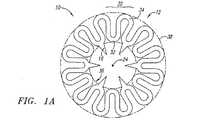
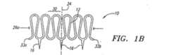
ここで、図面を参照すると、図1Aから図1Cは、切開部、穿孔部、または、組織を貫通する他の通路、例えば血管または他の体腔(図示せず)と連通する通路を閉塞するための閉塞装置すなわちクリップ10の好ましい第1の実施形態を示している。クリップ10は、その形状が略環状を成していても良く、且つ中心軸24を取り囲む本体12と、本体12から延びる複数の歯(tine)16とを有している。ここで使用されている「環状の本体」は、本体が略平坦であるか或いはかなりの厚さまたは深さを有しているかどうかにかかわらず、例えば1つの開口を取り囲む1つ以上の構造体を有する任意の中空体を含んでいる。したがって、環状の本体は、円形を成している場合であっても、他の非円形形状、例えば楕円形または中心軸に対して非対称な他の形状を含んでいても構わない。 Referring now to the drawings, FIGS. 1A-1C are intended to occlude an incision, perforation, or other passage through tissue, such as a passage communicating with a blood vessel or other body cavity (not shown). 1 shows a first preferred embodiment of an occlusion device or
本体12は、互いに接続されて本体12を形成する、複数のループ状部材または湾曲部材30を有していても良い。各ループ状部材30は、内側湾曲部位すなわち第1の湾曲部位32と、外側湾曲部位すなわち第2の湾曲部位34とを有していても良い。好ましい実施形態において、第1および第2の湾曲部位32、34は、互いに位相が一致せず、互いに交互に接続されており、これにより、無端正弦波パターンを形成している。また、正弦波パターンの代わりに、周期的に繰り返す他の略ジグザグパターン、例えば鋸の歯のパターンまたは正方形の歯のパターン(図示せず)が形成されても良く、これにより、本体12の周りで互い違いになる内側部位および外側部位を形成しても良い。図1Aに示されるように、クリップ10が略平面形態を成している場合、第1の湾曲部位32が本体12およびクリップ10の内周36を画定し、第2の湾曲部位34が外周38を画定しても良い。 The
複数の歯16は、ほぼ内側に延びるように、例えば互いの方に向けて及び/又は中心軸24に向かって延びるように付勢されていても良い。歯16は、第1の湾曲部位32上に配置されていても良く、また、クリップ10が平面形態を成す場合には中心軸24に向かって方向付けられていても良い。好ましい実施形態において、これらの歯16は、互いに向き合って対を成していても良く、あるいは、中心軸24に対して対称に設けられていても良い。 The plurality of
歯16は、バヨネット端部等の様々な尖端部を有していても良く、及び/又は、組織に刺入する或いは組織と係合するための刺(図示せず)を有していても良い。例えば、クリップ10の刺入能力を高めるため、及び/又は、組織に刺入するために必要な挿入力を低減するため、各歯16は、歯16の一方側に沿って端部へと延びるテーパ状の縁部(図示せず)を有していても良い。また、各歯16には、歯16の両側に、端部に向かって延びるテーパ状の縁部が設けられていても良い。 The
また、図1Aから図1Cに示されるように、歯16は、第1の湾曲部位32上に1つおきに配置されても良い。したがって、少なくとも1つのジグザグパターン周期を隣り合う歯16同士の間に配置して、後述するようにクリップ10の柔軟性を高めても良い。 Further, as shown in FIG. 1A to FIG. 1C, every
図1Bおよび図1C(両端部33a、33bが互いに接続される場合)に示されるように、本体12及び/又は歯16は、平面形態において画定される平面に対して歯16が垂直に延びるように偏向され、それにより、クリップ10における垂直形態を形成することができる。図1Bに示されるように、垂直形態において、歯16は、中心軸24に対して略平行に方向付けられることが好ましい。垂直形態において、本体12は、中心軸24と略平行に延び、且つジグザグパターンの振幅にほぼ対応する、長さL1を画定する略環状を成すことができる。本体12は、例えばクリップ10を供給するために使用される供給装置(図示せず)の外面と一致する、略円形状または楕円形状(図示せず)をクリップ10が成すことができるように、十分に柔軟であることが好ましい。As shown in FIGS. 1B and 1C (when the
好ましい実施形態において、歯16及び/又は本体12は、垂直形態から図1Aの平面形態へと動くように付勢されている。したがって、歯16が垂直形態にあると、歯16は、穿孔部位の組織に刺入し及び/又は穿孔部位の組織と係合することができる。クリップ10が解放されると、歯16は、クリップ10が平面形態へと動く時に、互いの方向に向けて戻ろうとし、これにより、後述するように、係合する組織を一緒に引き寄せて、穿孔部位を実質的に閉塞し及び/又はシールする。 In a preferred embodiment,
ループ状部材30は、クリップ10が平面形態と垂直形態との間で変形される際に、クリップ10内の応力を分配することができ、それにより、供給中にクリップ10を塑性変形させ、破壊し、あるいは、損傷させる虞がある局所的な応力を最小限に抑えることができる。また、クリップ10が垂直形態を成すと、ループ状部材30は、図1Bに示される収縮状態と、図1Cに示される拡張状態との間で動くことができる。ループ状部材30は、拡張状態へと付勢されるが、例えばクリップ10を押え付けることにより収縮状態へと圧縮できることが好ましい。あるいは、ループ状部材30の一部だけ、例えば第1の湾曲部位32だけが拡張状態へと付勢されても良く、及び/又は、ループ状部材30が収縮状態へと付勢されても良い。また、ループ状部材30は、供給装置(図示せず)に取り付ける前にクリップ10を平面形態から垂直形態へと移行させるために、クリップ10に作用させる必要がある力を減少させる。 The loop-shaped
クリップ10が垂直形態を成している状態で、ループ部材30は、クリップ10が図1Bに示されるような第1の直径または円周26aを画定するまで、収縮状態へと周方向及び/又は径方向に圧縮できる。クリップ10は、例えば後述するように供給装置(図示せず)のキャリアアセンブリに対してクリップ10を取り付けることにより、収縮状態に押え付けられても良い。クリップ10は、押え付けられた状態から解放されると、例えばキャリアアセンブリから展開されると、図1Cに示されるように拡張状態へと自動的に拡張することができ、それにより、第2の直径または円周26bを画定することができる。このように、ループ状部材30は、例えば小さな穿孔部または通路を通じたクリップ10の導入を容易にするため、供給中にクリップ10の外形を簡単に小さくすることができる。後述するように、クリップ10が供給装置から完全に展開されると、ループ状部材30は、クリップ10が平面形態へと戻る際に、弾性的に拡張することができる。 With
クリップ10(または、ここで説明する他のいずれのクリップも同様に)を製造するため、本体12および歯16は、1枚のシート材料、例えばニッケル・チタン合金(「ニチノール」)等の超弾性合金から一体的に形成されても良い。シートの一部は、クリップを形成するために、レーザ切断、化学エッチング、光化学エッチング、放電加工機(EDM)等を使用する打ち抜き加工等の従来の方法を使用して除去されても良い。歯16は、先端まで鋭くされても良い。すなわち、化学エッチングや機械的研削等の従来の方法を使用して、歯16に端部が形成されても良い。 To manufacture clip 10 (or any other clip described herein),
クリップ10は、電気研磨、化学エッチング、タンブリング、サンドブラスト、サンディング等の従来の方法を使用して、所望の仕上がり状態まで研磨されても良い。研磨は、クリップ10を形成するために使用される方法に応じて、様々な機能を果たすことができる。レーザ切断により、あるいは、EDMを使用して形成されるクリップの場合、研磨は、クリップから熱影響域(HAZ)及び/又はギザギザを除去することができる。光化学エッチングによって形成されたクリップの場合、研磨は、より滑らかな仕上がり面を形成することができる。打ち抜き加工によって形成されたクリップの場合、研磨は、クリップの底面からギザギザを除去または減らすことができ、及び/又は、打ち抜き加工プロセスによってクリップの上側に生じる「ロール」を平らにすることができる。
これに加え、あるいは、これに代えて、クリップ10は、形状記憶合金、例えばニチノールによって形成されても良い。この場合、最初に、ループ状部材30が収縮状態に形成され及び/又はクリップ10が平面形態で形成される。クリップ10を垂直形態に変形させた状態で、例えばクリップ10の内面に対して径方向外側に力を作用させることにより、クリップ10を拡張させ、それにより、ループ状部材30を拡張状態まで拡張させても良い。その後、当業者に知られているように、例えばクリップ10をオーステナイト状態まで加熱することにより、ループ状部材30を加熱処理し、ループ状部材30に拡張状態を「記憶させる」ようにしても良い。また、当業者に知られているように、更に例えば歯が平面形態にある状態でクリップ10を更に加熱処理して、本体12及び/又は歯16を「記憶させて」平面形態へと付勢する必要があるかもしれない。その後、クリップ10は、例えば周囲の温度またはそれに近い温度であっても良いマルテンサイト状態まで冷却されるとともに、操作され、例えば、後述するようにクリップ10を供給装置(図示せず)に取り付けることにより垂直形態まで可鍛変形されても良い。このように、クリップ10が、その後に、所定温度まで、例えば体温またはそれ以下の温度まで加熱される場合には、材料は、平面形態及び/又は拡張状態を記憶しても良く、また、それらの形態および状態へと付勢されるようになっていても良い。 In addition, or alternatively, the
図2Aから図2Cは、平面を画定し且つこの平面を貫通して延びる中心軸124を中心に配置された略環状の本体112を有する、他の好ましい実施形態の閉塞装置、すなわちクリップ110を示している。前述の実施形態と同様に、本体112は、互いに接続されて本体112を形成する複数のループ状部材130を有していることが好ましい。各ループ状部材130は、内側湾曲部位すなわち第1の湾曲部位132と、外側湾曲部位すなわち第2の湾曲部位134とを有している。前述の実施形態と同様に、第1および第2の湾曲部位132、134は、無端正弦波パターンまたは他の略ジグザグパターンを形成しても良い。図2Aに示されるようにクリップ110が略平面形態を成している場合、第1の湾曲部位132が内周136を画定し、第2の湾曲部位134が外周を画定しても良い。 FIGS. 2A-2C illustrate another preferred embodiment occlusion device, or
前述の実施形態とは異なり、クリップ110は、複数の主歯114と、複数の副歯116とを有している。前述の実施形態と同様に、主歯および副歯114、116のそれぞれは、様々な周知の尖端部を有していても良い。 Unlike the above-described embodiment, the
各主歯114が同じ所定の長さl1を有していても良いが、各主歯114が互いに異なる長さを有していても良い。主歯114は、対向する1つ以上の対を成して、例えば対向する第1の湾曲部位132上に配置されても良く、平面形態においては中心軸124に向かって及び/又は中心軸124を横切って方向付けられていても良い。平面形態において、長さl1は、主歯114の少なくとも一部が互いに重なり合うように、すなわち、主歯114が対向する歯114に向かって中心軸124を横切って延びるように、十分に長くても良い。したがって、主歯114の端部が中心軸124を通り過ぎて延びていても良く、及び/又は、クリップ110が平面形態を成している場合には、各対の主歯114が互いに略平行に位置していても良い。Each
各副歯116は、例えば対向する主歯114の対同士の間に1つ以上の副歯116が設けられるように、第1の湾曲部位すなわち内側湾曲部位132上に配置されていても良い。各副歯116は、主歯114の長さl1よりも実質的に短い長さl2を有していても良い。Each
副歯116は、各主歯114の両側に配置されていることが好ましい。例えば、図2Aから図2Cに示されるクリップ110は、第1および第2の主歯114を有しており、第1および第2の主歯114のそれぞれが、その両側に副歯116を有している。したがって、クリップ110は、全体で、2つの主歯114と、4つの副歯116とを有している。随意的に、副歯116は、中心軸124に対して略対称に配置されていても良い。歯114、116は、第1の湾曲部位132上に1つおきに設けられても良い。例えば、主歯114も副歯116も有していない第1の湾曲部位132は、隣り合うそれぞれの歯を分離しても良く、例えば2つの隣り合う副歯116同士を分離し、または、副歯116と主歯114とを分離しても良い。 The
図2Bおよび図2Cに示されるように、本体112及び/又は歯114、116は、それらが図2Aで画定される平面に対して垂直に延びるように偏向されても良い。主歯114および副歯116は、図1Bに示されるように垂直形態を形成するため、中心軸124と略平行に方向付けられることが好ましい。垂直形態において、本体112は、中心軸124と略平行に延び、且つ正弦波パターンの振幅にほぼ対応する、長さLE1を画定する略環状を成している。本体112は、例えば供給装置(図示せず)の外面と一致する略円形状または楕円形状(図示せず)をクリップ110が成すことができるように十分に柔軟であることが好ましい。As shown in FIGS. 2B and 2C, the
前述の実施形態と同様、歯114、116は、互いの方向に付勢され及び/又は中心軸124に向けて付勢され、すなわち、クリップ110の付勢に起因して図2Aの平面形態に向けて付勢されても良い。クリップ110が垂直形態を成す状態で、クリップ110は、後述するように、主歯114が血管または他の体腔の壁に完全に刺入する一方で、副歯116がその相対的な長さに起因して一部だけ上記壁に刺入するように供給されても良い。 Similar to the previous embodiment, the
前述の実施形態と同様に、ループ状部材130は、図2Bに示される収縮状態と、図2Cに示される拡張状態との間で伸縮することができる。ループ状部材130は、拡張状態へと付勢されることが好ましいが、例えばクリップ110を押え付けることにより、収縮状態へと弾性的に圧縮することができる。 Similar to the previous embodiment, the
図3を参照すると、前述の実施形態と同様にループ状部材130と主歯114とを有する本体112を備えているが、補助歯すなわち副歯116を有していない、他の実施形態のクリップ210が示されている。クリップ210の要素における参照符号は、クリップ110において使用された要素のそれと同じである。 Referring to FIG. 3, the clip of another embodiment that includes a
本発明のクリップのいずれも、1つ以上の放射線不透過性の指標、または蛍光透視等の外部画像を使用して見ることができる他の指標を有していても良い。例えば、一例として図2Aから図2Cのクリップ110を使用し、金、白金、白金/イリジウム等の高密度材料であっても良い放射線不透過性材料を用いて、クリップ110の全体をコーティングしても良い。 Any of the clips of the present invention may have one or more radiopaque indicators or other indicators that can be viewed using an external image, such as fluoroscopy. For example, the
また、マスキング技術を使用して、クリップ110の一部を放射線不透過性材料でコーティングしても良い。例えば、クリップ110の全体を最初に放射線不透過性材料でコーティングしても良い。その後、放射線不透過性コーティングが望ましい位置でクリップ110にマスクをかけても良い。例えば、ループ状部材130を放射線不透過性材料でコーティングしないままにすることが望ましい場合には、このプロセス中において、クリップ110のループ状部材130にマスクをかけない状態にしても良い。このようなことは、例えば放射線不透過性材料がループ状部材130の柔軟性に悪影響を与えないようにするために望ましいかもしれない。その後、クリップ110を処理して、マスクされていない領域から、この例ではループ状部材130から、放射線不透過性材料を除去しても良い。その後、従来のプロセスを使用してマスキングを除去し、クリップ110の残りの部分を放射線不透過性材料でコーティングされたままにしておく。 Alternatively, a portion of
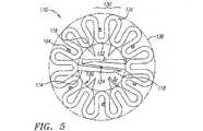
図4を参照すると、他の変形例においては、クリップ110の所定の位置に1つ以上の指標102が設けられていても良い。例えば、対向する2つのループ状領域または円形領域130に、高密度の或いは放射線不透過性の材料102がクリンプされ或いは固定されている。図5に示される他の実施形態において、ループ状部材130には、高密度プラグ(図示しない)を接着または固定することができる複数のポケット104が設けられている。また、これらの様々な放射線不透過性の指標は、ここで説明する任意の実施形態に組み込まれても良い。 Referring to FIG. 4, in another modification, one or
図6を参照すると、クリップ110と同様に互いに接続して本体312を形成する複数のループ状部材330を有していても良い、他の実施形態のクリップ310が示されている。各ループ部材330は、第1の湾曲部位すなわち内側湾曲部位332と、第2の湾曲部位すなわち外側湾曲部位334とを有していても良い。主歯314は、対向する第1の湾曲部位332に配置されていても良く、随意的に、組織との係合を高めるための刺302を有していても良い。副歯316は、各主歯314の両側の第1の湾曲部位332上に設けられていても良い。また、歯314、316を有していない第1の湾曲部位332は、前述の実施形態で前述したように、隣り合う歯同士を分離しても良い。 Referring to FIG. 6, there is shown another embodiment of a
また、クリップ310は、1つ以上の歯314、316に、例えば各第1の湾曲部位332に隣接して、ストッパ部材306を有している。各ストッパ部材306は、鈍形状、例えば略三角形状を成していても良い。この場合、ストッパ部材306の先端307は、第1の湾曲部位332から延びており、歯314、316は、ストッパ部材306の幅広い或いは鈍状の基部307から延びている。使用中、鈍状の基部307は、各歯314、316の有効長を減少させることにより、組織内への各歯314、316の刺入を制限することができる。例えば、歯314、316が組織へと打ち込まれると、歯314、316は、鈍状の基部307が組織と接触するまで組織に刺入することができ、これにより、歯314、316が組織内にそれ以上刺入するのを防止できる。 In addition, the
図7を参照すると、本体412と、複数の歯414と、隣り合う歯414同士を互いに接続する複数のスプリング部材440(i)とを有する、他の実施形態のクリップ410(i)が示されている。本体412は、隣り合う歯414同士の間で延びる外側湾曲部位434を有しており、これにより、クリップ410(i)のための外周を画定している。クリップ410(i)は、略平面形態、例えば図7に示される平面形態と、垂直形態(図示せず)との間で動くことができ、前述の実施形態と同様に、平面形態へと付勢されることが好ましい。 Referring to FIG. 7, there is shown another embodiment clip 410 (i) having a
図示の実施形態において、スプリング部材440(i)は、一般に、クリップ410(i)が平面形態を成している時に、本体412の中心軸424に向けて方向付けられる内側湾曲部位432(i)を有する、中空ダイヤモンド形状部材である。スプリング部材440(i)は、複数の目的を果たすことができる。第1に、スプリング部材440(i)は、例えばクリップ410(i)の少なくとも一部を弾性的に拡張させることができるようにクリップ410(i)を付勢することができる。例えば、クリップ410(i)が垂直形態(図示せず)へと偏向されると、スプリング部材440(i)により、歯414を中心軸424から及び/又は互いから離すことができる。したがって、展開中、歯414は、径方向外側に偏向でき、あるいは、拡張して組織のより大きな領域と係合することができる。 In the illustrated embodiment, the spring member 440 (i) generally has an inner curved portion 432 (i) that is directed toward the
歯414が広げられると、スプリング部材440(i)は、変形して幅広くなり(隣り合う歯414同士のほぼ間で延びる寸法に沿って)且つ短くなる(歯414と略平行に延びる寸法に沿って)。歯414を広げる力が除去されると、スプリング部材414(i)は、その当初の形状へと戻ろうとし、それにより、歯414を互いに近づくように引き寄せることができる。 As the
また、スプリング部材414(i)の内側湾曲部位432(i)は、前述したストッパ部材と同様に、組織内への歯414の刺入を制限するストッパを形成しても良い。例えば、クリップ410(i)が垂直形態を成し、且つスプリング部材414(i)が拡張されると、内側湾曲部位432(i)が更に斜めになって略直線状になる。したがって、歯414が組織中へと打ち込まれると、内側湾曲部位432(i)は、歯414の刺入を制限することができる。 Further, the inner curved portion 432 (i) of the spring member 414 (i) may form a stopper that restricts the insertion of the
最後に、クリップ410(i)が展開されると、例えば、歯414が組織内に刺入されると、内側湾曲部位432(i)は、その当初の形状に戻ることができるとともに、内側湾曲部位432(i)と隣り合う歯414との間で組織を締め付け、或いは組織と係合することができる。このように、スプリング部材440(i)を収縮させると、例えば係合組織をクリップ410(i)の中心軸424に向けて内側に引き寄せることにより、穿孔部位をシールできるクリップ410(i)の能力を高めることができる。 Finally, when the clip 410 (i) is deployed, for example, when the
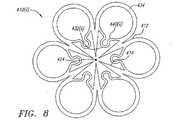
図8を参照すると、スプリング部材440(ii)の形状以外が図7に示されるクリップ410(i)とほぼ同様の、他の実施形態のクリップ410(ii)が示されている。スプリング部材440(ii)は、ダイヤモンド形状部材ではなく、円形状をほぼ画定するループ状部材である。 Referring to FIG. 8, there is shown a clip 410 (ii) of another embodiment that is substantially similar to the clip 410 (i) shown in FIG. 7 except for the shape of the spring member 440 (ii). The spring member 440 (ii) is not a diamond-shaped member but a loop-shaped member that substantially defines a circular shape.
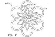
ここで、図12を参照すると、本発明の他の好ましい実施形態のクリップ710が示されている。前述の実施形態と同様に、クリップ710は、平面を画定する略環状の本体712を有している。本体712は、平面を貫通して延びる中心軸724周りに配置されている。本体712は、隣り合う歯716同士の間で延び、且つ互いに接続されて本体712を形成する、複数の外側湾曲部材730を有していることが好ましい。図12に示されるようにクリップ710が略平面形態を成している場合には、湾曲部材730がクリップ710の外周738を画定する。 Referring now to FIG. 12, another
歯716は、湾曲され或いは弓型に形成されており、クリップ710が略平面形態を成す時に中心軸724に向けて延びる先端部715を有している。随意的に、1つ以上の歯716は、前述の実施形態と同様に、刺717を有していても良い。歯716が中心軸724を中心に螺旋を描くように、歯716の湾曲形状は全て互いに一致している(in phase with one another)ことが好ましい。これにより、本体712の所定の直径において、歯716の長さを最大にすることができる。 The
例えば、歯716の長さは、歯716の先端部715同士が接触しなければ、本体712の半径より長くても良い。このように、各歯716が弓型形状を成しているため、クリップ710の歯716を、同等の直径を有する前述のクリップの直線状の歯よりも概ね長くすることができる。したがって、歯716は、他のクリップの歯よりも深く組織中に刺入することができる。 For example, the length of the
前述の実施形態と同様に、クリップ710の本体712及び/又は歯716は、平面形態において画定される面に対して垂直に歯716が延びるまで偏向することができ、これにより、垂直形態を形成することができる。垂直形態においては、歯716を中心軸724と略平行に向けることができる。また、前述の実施形態と同様に、歯716及び/又は本体712は、垂直形態から平面形態へと動くように付勢されても良い。クリップ710は、本発明の他のクリップに関して後述する方法と略同じ方法で供給されても良い。 Similar to the previous embodiment, the
本発明のいずれのクリップも、例えば血管の内面上の内皮の再生速度を高めることにより、又は処置部位での炎症反応を減らすことにより、血管の止血及び/又は治癒を高める物質を用いてコーティングされても良い。一実施形態においては、内皮細胞を表面に引き付けるのに適した合成ペプチドコーティングがクリップに付与されても良い。典型的な合成ペプチドコーティングは、例えば、コラーゲンと同じ細胞接着部位に付着する。他の実施形態において、クリップは、止血を促進するため、凝固因子の組み合わせを用いてコーティングされても良い。例えば、内因性凝固経路を促進するため、クリップの一方側が因子IIIおよびエンドペプチダーゼ、例えばPTAでコーティングされても良い。クリップの反対側では、外因性凝固経路を促進するため、プロテイン共同因子プロアクセレリン(因子V)と活性エンドペプチダーゼとの組み合わせ、例えば血清プロトロンビン転換促進因子(SPCA)、コトロンボプラスチン等が加えられても良い。また、本発明のクリップは、体液の存在下で膨らんで血流を低下、最小化、停止させることにより止血プロセスを助ける、任意の適当な親水性高分子を用いてコーティングされても良い。 Any clip of the present invention is coated with a substance that enhances vascular hemostasis and / or healing, for example, by increasing the regeneration rate of the endothelium on the inner surface of the blood vessel or by reducing the inflammatory response at the treatment site. May be. In one embodiment, the clip may be provided with a synthetic peptide coating suitable for attracting endothelial cells to the surface. A typical synthetic peptide coating attaches to the same cell adhesion site as, for example, collagen. In other embodiments, the clip may be coated with a combination of clotting factors to promote hemostasis. For example, one side of the clip may be coated with factor III and an endopeptidase such as PTA to promote the intrinsic clotting pathway. On the other side of the clip, a combination of protein cofactor proacelelin (factor V) and an active endopeptidase, such as serum prothrombin conversion promoting factor (SPCA), cothromboplastin, etc. is added to promote the extrinsic coagulation pathway. Also good. The clip of the present invention may also be coated with any suitable hydrophilic polymer that swells in the presence of bodily fluids to assist in the hemostatic process by reducing, minimizing, and stopping blood flow.
本発明のクリップは、様々な装置および方法を使用して供給することができる。本発明のクリップを供給するための典型的な装置500が図9に示されている。本発明のクリップを供給するために使用できる他の適した装置は、本出願と同じ日に提出され、且つ本出願の譲受人に譲渡された「閉塞装置を供給するための装置および方法」と題する、同時係属出願である米国特許出願第10/081,723号に開示されている。この出願およびここで引用された任意の引例の開示内容は、参照により明確に本願に組み込まれる。 The clips of the present invention can be supplied using a variety of devices and methods. An
一般に、装置500は、導入シース552と、シース552上に摺動可能に配置されたハウジングまたはキャリアアセンブリ554とを有している。シース552は実質的に柔軟な或いは半硬質の管状体558を有しており、管状体558は、その基端部562と先端部564との間で延びるルーメン560を有している。先端部564は、血管内への挿入を容易にするべくサイズおよび形状が設定されており、例えば、通路を通じたその少なくとも一部の血管内へのほぼ非侵襲的な導入を容易にする、テーパ状の先端を有している。ルーメン560は、カテーテルやガイドワイヤ等(図示せず)の1つ以上の装置を挿通できるサイズを有している。また、シース552は、流体密なシールを形成する基端部562または基端部562の近傍のルーメン560内に、止血弁等の1つ以上のシール(図示せず)を有していることが好ましく、更に、流体がシース552の基端側へと流れないように、1つ以上の装置をルーメン560内に挿入収容できることが好ましい。 In general, the
随意的に、シース552は、例えば流体をルーメン560内に供給するためにルーメン560と連通する、サイドポート566を有していても良い。これに代えて、あるいは、これに加えて、サイドポート566は、「血液逆流(bleed back)」インジケータを形成するために使用されても良い。典型的な「血液逆流」インジケータおよび関連する使用方法は、2000年10月6日に提出され且つ本出願の譲受人に譲渡された「血管シースを位置決めするための装置および方法」と題する同時係属出願である第09/680,837号に開示されている。この出願およびここで引用された任意の引例の開示内容は、参照により全体として本願に組み込まれる。 Optionally, the
また、装置500は、機械式位置決め装置すなわち閉塞具600、例えば、参照により本願に組み込まれる前述した米国特許出願第10/081,723号に開示された閉塞具であって、シース552の基端部に取り付けることができるアクチュエータアセンブリ(図示せず)の一部品であっても良い閉塞具を有していても良い。また、機械式位置決め装置すなわち閉塞具600は、例えばアクチュエータアセンブリを通じてルーメン560内に挿入可能な別個の装置であっても良い。一般に、閉塞具600は、先端チップ614と先端部616とを有する長尺な部材である。先端チップ614をほぼ非侵襲的に血管590(図示せず、図10Aから図10Dを参照)内に挿入できるように、先端チップ614は実質的に柔らかく及び/又は曲げ易くても良い。先端部616は、一般に、後述するように触覚フィードバックを形成するための、1つ以上の翼部あるいは他の拡張可能部材618を有している。 The
キャリアアセンブリ554は、シース552の外面上に摺動可能に配置されるとともに、ここで説明するどのようなクリップであっても良いクリップ110(破線で示されている)を、解放可能に支持することができるように構成されている。キャリアアセンブリ554は、ほぼ永久的にシース552に対して取り付けられても良く、及び/又は、展開中に先端側へとクリップ110を押し進めるために、例えばアクチュエータアセンブリ(図示せず)によって、シース552の基端部562から作動されても良い。あるいは、クリップ110は、本出願と同じ日に提出され、且つ本出願の譲受人に譲渡された「閉塞装置を供給するためのシース装置および方法」と題する、同時係属出願である米国特許出願第10/081,725号に開示されるようなアクチュエータアセンブリによって支持されても良い。この出願およびここで引用された任意の引例の開示内容は、参照により明確に本願に組み込まれる。
図10Aから図10Dを参照すると、装置500は、クリップ110を供給して、切開部、穿孔部、あるいは、患者の皮膚594から介在組織596を通じて血管590または他の体腔の壁598へと延びる他の通路592を、閉じ及び/又はシールするために使用することができる。また、装置500は、クリップ110を供給して、他の処置において組織と係合するため、例えば組織部分を互いに接続するため、あるいは、組織構造を互いに対して固定するために使用することができる。例えば、装置500およびクリップ110は、バイパス処置中に吻合部を付着させるために使用することができる。当業者であれば分かるように、クリップ110及び/又は装置500は、様々な処置で役立つ。 Referring to FIGS. 10A-10D, the
図10Aに示されるように、シース552は、通路592を通じて、血管590内に挿入され或いは位置決めされても良い。シース552は、通路592を通じて血管590内へと予め位置決めされたガイドワイヤまたは他のレール(図示せず)上にわたって押し進められ、あるいは、従来の処置を使用して、先の尖ったスタイレットと共に直接に組織を通じて押し進められても良い。血管590は、大腿動脈、橈骨動脈、頸動脈等の末梢血管であることが好ましいが、当業者であれば分かるように、シース552を使用して他の体腔へアクセスすることもできる。 As shown in FIG. 10A,
通路592、したがって、シース552を、血管590に対して「α」の角度で方向付けることにより、血管590を損傷させる危険を最小限に抑えつつ、シース552のルーメン560を通じた血管590内への装置の導入を容易にしても良い。ガイドワイヤやカテーテル等の1つ以上の装置(図示せず)が、シース552を通じて挿入され、患者の体内の所望部位へと押し進められても良い。例えば、装置は、血管形成術やアテローム切除術、ステント移植等の治療または診断処置を、患者の脈管構造内で行なうために使用されても良い。 By orienting
処置完了後、処置中に使用された任意の装置をシース552から除去するとともに、閉塞具600をルーメン560内に挿入することができる。例えば、閉塞具600は、アクチェータアセンブリ(図示せず)の一部であっても良く、また、アクチュエータアセンブリがシース552の基端部に取り付けられる場合には、ルーメンを通じて押し進められても良い。また、アクチュエータアセンブリおよび閉塞具600がシース552に対して個別に接続されても良い。 After the procedure is complete, any device used during the procedure can be removed from the
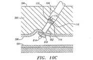
閉塞具600がシース552内に完全に挿入されると、閉塞具600の先端部616は、シース552の先端部564を超えて延びることができる。他の実施形態において、閉塞具600は、例えばシース552および閉塞具600の、協働するスロットや溝等(図示せず)を含むトラックに沿って、シース552の外面(図示せず)に取り付けられても良い。 When the
図10Bを参照すると、例えば閉塞具600の基端部のスイッチ(図示せず)を作動させることにより、閉塞具600の先端部の拡張可能部材618が拡張形状にされても良い。シース552と閉塞具600とを互いに連結した状態で、シース552および閉塞具600を一緒に移動させても良い。 Referring to FIG. 10B, the
図10Cに示されるように、シース552は、拡張可能部材618が血管590の壁598と接触するまで、血管590から部分的に抜去されても良い。このようにすると、拡張可能部材618は、血管590の壁598に対するシース552の位置を触覚で示すことができる。また、拡張可能部材618は、例えばクリップ110を受けるための血管590の壁598を「明らかにする」ことを助けることができる。 As shown in FIG. 10C, the
一般に、クリップ110は、処置前に、キャリアアセンブリ554によって支持される。クリップ110は、その垂直形態でキャリアアセンブリ554上に拘束されても良く、また、キャリアアセンブリ554は、シース552の基端部またはその近傍に設けられても良い。主歯114および副歯116を有していても良い歯が、互いの方向に付勢されているため、歯114、116は、キャリアアセンブリ554の内面(図示せず)またはシース552の外面と摺動可能に接触することができ、それにより、クリップ110をその垂直形態に拘束することができる。 In general, the
図10Dを参照すると、その後、シース552が適切に位置決めされた状態で、キャリアアセンブリ554を作動させることにより、例えば、キャリアアセンブリ554をシース552上にわたって先端側へと押し進めて、クリップ110を供給することができる。キャリアアセンブリ554を、シース552の先端に対して、したがって、閉塞具600の拡張可能部材618に対して、予め定められた距離だけ押し進め、それにより、クリップ110を血管590の壁598に対して実質的に係合させるようにすることが好ましい。この予め定められた距離により、血管590の壁598に対してクリップ110を適切に展開させることが容易になり、例えばクリップ110を余計に押し進めてしまうこと、すなわち、クリップ110を血管590内に押し進めてしまうことを防止できる。 Referring to FIG. 10D, then, with the
クリップ110がキャリアアセンブリ554から展開されると、クリップ110は拡張して直径が拡大する。例えば、キャリアアセンブリ554の先端部は、クリップ110の歯114、116及び/又は本体を、径方向外側に偏向させることができる傾斜部位(図示せず)を有していても良い。クリップ110がこの傾斜部位上にわたって押し進められると、歯114、116は、それらが周囲の組織へと打ち込まれる際に径方向外側に偏向され、それにより、歯114、116がほぼ軸方向に維持されている場合よりも広い領域の組織と、係合することができる。 As the
また、クリップ110は、クリップ110がキャリアアセンブリ554及び/又はシース552から展開される際にクリップ110の拡張を容易にする、前述したような拡張可能なループ状部材及び/又はスプリング部材(図示せず)を有していても良い。例えば、クリップ110のループ状部材は、クリップ110がキャリアアセンブリ554に取り付けられる際に圧縮されても良く、それにより、例えば比較的外形が小さいキャリアアセンブリ554を使用できる。クリップ110は、血管590の壁598の動脈切開部591(図11A参照)等の開口を取り囲む組織の広い領域と係合するように、キャリアアセンブリ554からの展開時に自動的に拡張されても良い。 The
クリップ110がシース552から完全に展開され或いは解放されると、クリップ110は、図11Bに示されるように、その略平面形態へと弾性的に変形することができる。 When the
クリップ110の供給中に、例えば蛍光透視を使用して、クリップ110上の放射線不透過性指標(図示せず)、キャリアアセンブリ554、及び/又は、拡張可能部材618を監視し、装置500の観察及び/又は位置決めを容易にしても良い。したがって、クリップ110がキャリアアセンブリ554から展開される前に、拡張可能部材618に対する、したがって血管590の壁598に対する、クリップ110の相対的な位置を確かめることができる。 During delivery of
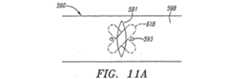
図11Aおよび図11Bを参照すると、好ましい実施形態において、閉塞具600の拡張可能部材618は、クリップ110の1つ以上の歯114から回転方向にオフセットされても良い。例えば、クリップ110が主歯(例えば、図2Aおよび図3に示される主歯)を有している場合、閉塞具600およびクリップ110は、中心軸124を中心に所定の相対角度方向を有していても良い。好ましくは、クリップ110が所定の角度方向でキャリアアセンブリ554に取り付けられ、また、オフセットされた所定の角度方向でのみシース552内に閉塞具600を受け取ることができ、それにより、図11Aに示されるように、歯114、116は、拡張可能部材618と軸方向で位置合わせされない。 With reference to FIGS. 11A and 11B, in a preferred embodiment, the
この所定の回転方向により、主歯114が拡張可能部材618と接触し及び/又は損傷させる可能性をほぼ最小限に抑えることができる。例えば、特に図11Aを参照すると、クリップ100と閉塞具600との好ましい相対角度方向が、血管590の壁598の動脈切開部591に対して示されている。ここで、拡張可能部材618は、血管590の内部で動脈切開部591と対角線的に交差するように方向付けられる。一般に、血管壁組織の固有の構造により、動脈切開部は、一般に、血流方向(すなわち、血管壁の周線を横切る方向)に対して垂直に延びる細長い形状を成す傾向にある。 This predetermined direction of rotation can substantially minimize the possibility that the
主歯114は、図示のように、主歯114が動脈切開部591の両側で血管590の壁598に突き刺さるように方向付けられる。拡張可能部材618が対角線的に交差した状態では、主歯114と接触する虞が実質的に低減される。したがって、主歯114は、拡張可能部材618を回避しながら血管590の壁598を完全に貫通して延びる程度に、十分長くても良い。 The
その後、拡張可能部材618は、収縮され及び/又はシース552の先端部564内に回収されても良い。クリップ110がシース552から完全に解放されると、図11Bに示されるように、主歯114の一部が重なり合い、1本の糸による縫合と同様に、動脈切開部591を引き寄せて閉じることができる。例えば、拡張可能部材618は、クリップ110がキャリアアセンブリ554から展開される前または後、あるいは、キャリアアセンブリ554がその最先端位置に達した際、直ちに、自動的に収縮されても良い。閉塞具600の先端部616は、主歯114が血管590の壁598に突き刺さった後であってクリップ110がシース552から完全に解放される前に、収縮されてシース554内に回収されることが好ましい。 Thereafter, the
また、クリップ110が副歯116(例えば、図2Aに示される副歯)を有している場合には、クリップ110の展開中に副歯116の一部が血管590の壁598に突き刺さっても良い。好ましくは、副歯116の長さは比較的短く、あるいは、副歯116が壁598を完全に貫通して突き刺さらないようにするストッパ部材(図示せず)が設けられていても良い。クリップ110が解放されると、副歯116は、組織を内側に引き寄せ、巾着縫合(purse−string suture)にやや類似した態様を成して、動脈切開部591の閉塞を促進することができる。 Further, when the
例えば動脈切開部591の両側で、クリップ110が血管590の壁598内にうまく展開されると、装置500を通路592から抜去することができる。装置500全体が一段階で除去されても良く、あるいは、閉塞具600を最初にシース552から抜去し、その後にシース552を回収することにより、クリップ110を所定の位置に残して、動脈切開部591を閉塞し及び/又は通路592をシールしても良い。また、望ましい場合には、当業者に知られているように、クリップ110の供給と共にあるいはクリップ110の供給とは別個に、封止剤または他の材料を通路592内に導入して、通路592を更にシールしても良い。 For example, on both sides of the
本発明は、様々な変更および他の形態を成すことができるが、その特定の例を図面に示し、且つここで詳細に説明してきた。しかしながら、本発明は、開示された特定の形態または方法に限定されず、むしろ、本発明は、添付の請求項の精神および範囲内に入る全ての変更例、等価物、変形例を網羅するものであることは言うまでもない。 While the invention is susceptible to various modifications and other forms, specific examples thereof have been shown in the drawings and have been described herein in detail. However, the invention is not limited to the specific forms or methods disclosed, but rather the invention encompasses all modifications, equivalents, and variations that fall within the spirit and scope of the appended claims. Needless to say.
Claims (44)
Translated fromJapanese第1の湾曲部位から延びる複数の歯を備え、これらの歯は、平面形態においては、ほぼ中心軸に向かって方向付けられ、垂直形態においては、中心軸と略平行に方向付けられる、
組織と係合する装置。A substantially annular main body is provided that defines a plane and is arranged around a central axis that extends substantially orthogonal to the plane, the main body having a vertical configuration extending out of the plane from a substantially planar configuration lying substantially in the plane. The main body includes a plurality of loop-shaped members alternately having first curved portions and second curved portions, and in the planar form, the first curved portions are arranged on the inner periphery of the main body. And the second curved portion defines the outer periphery of the body,
A plurality of teeth extending from the first curved portion, the teeth being oriented generally toward the central axis in the planar configuration and oriented generally parallel to the central axis in the vertical configuration;
A device that engages tissue.
第1の長さを有する第1の主歯と、
第2の長さを有する第2の主歯と、
を備え、
第1および第2の主歯は、対向する第1の湾曲部位に配置されるとともに、平面形態においては互いの方に向かって方向付けられ、第1および第2の長さによって、第1および第2の主歯は、平面形態においてその少なくとも一部が互いに重なり合う、請求項1に記載の装置。Multiple teeth
A first main tooth having a first length;
A second main tooth having a second length;
With
The first and second main teeth are disposed at opposing first curved portions and are directed toward each other in a planar configuration, and the first and second lengths allow the first and second teeth to be The apparatus of claim 1, wherein the second main teeth overlap at least partially with each other in a planar configuration.
第1の長さを有し、平面形態においては環状の本体からほぼ中心軸に向かって延びるとともに、本体が垂直形態へと動く際に平面外に偏向することができる第1の主歯と、
第2の長さを有し、本体が平面形態に配置されている時には環状の本体から第1の主歯に向かって延びるとともに、本体が垂直形態へと動く時には平面外に偏向することができる第2の主歯と、
を備え、
第1および第2の長さによって、第1および第2の主歯は、平面形態においてその少なくとも一部が重なり合う、
組織と係合する装置。A substantially annular body that defines one plane and is arranged around a central axis that extends substantially orthogonal to the plane, from a substantially planar configuration that lies substantially in the plane to a vertical configuration that extends out of the plane. A body that can move,
A first main tooth having a first length, extending in a planar configuration from an annular body substantially toward the central axis and capable of deflecting out of the plane as the body moves to a vertical configuration;
It has a second length and extends from the annular body toward the first main teeth when the body is arranged in a planar configuration and can deflect out of the plane when the body moves to a vertical configuration. A second main tooth;
With
Depending on the first and second lengths, the first and second main teeth overlap at least partially in a planar configuration,
A device that engages tissue.
平面形態においてはループ状部材から中心軸に向かって延び、垂直形態においては中心軸と略平行に延びる複数の歯を備え、これらの歯は、弛緩状態で互いに所定の間隔をもって離間する先端を備え、
ループ状部材と歯の先端との間で隣り合う歯同士の間に配置されたスプリング部材を備え、スプリング部材は、歯の先端同士を互いに弾性的に離間させることができる、
組織と係合する装置。A substantially annular main body that is disposed around a central axis that defines a plane and extends substantially orthogonal to the plane, the main body having a vertical configuration that extends out of the plane from a substantially planar configuration that lies substantially in the plane. The body comprises a plurality of loop members extending around the outer periphery of the body,
The planar configuration includes a plurality of teeth extending from the loop-shaped member toward the central axis, and the vertical configuration extending substantially parallel to the central axis. The teeth include tips that are spaced apart from each other at a predetermined interval. ,
A spring member disposed between adjacent teeth between the loop-shaped member and the tip of the tooth, the spring member can elastically separate the tips of the teeth from each other;
A device that engages tissue.
平面形態においては湾曲部材から中心軸に向かって延びるとともに、垂直形態においては中心軸と略平行に延びる複数の弓形の歯を備えている、
組織と係合する装置。A substantially annular main body is provided that defines a plane and is arranged around a central axis that extends substantially orthogonal to the plane, the main body having a vertical configuration extending out of the plane from a substantially planar configuration lying substantially in the plane. The body comprises a plurality of curved members defining an outer periphery of the body;
A plurality of arcuate teeth extending from the curved member toward the central axis in the planar configuration and extending substantially parallel to the central axis in the vertical configuration;
A device that engages tissue.
長尺部材の先端部を、患者の皮膚から、組織を貫通する通路に沿って、体腔内へと押し進め、
長尺部材の先端部を超えて先端側へと、閉塞具の先端部を通路に沿って押し進めて、体腔内に位置決めし、
閉塞具の先端部上の1つ以上の拡張可能部材を横方向に拡張し、
拡張可能部材が体腔壁と接触するまで閉塞具を通路から引き出すことにより、長尺部材と閉塞具の複数の拡張可能部材との間にある体腔壁の位置を触覚的に示し、
クリップの歯が体腔壁に刺入するまで、長尺部材上にわたって通路内にクリップを押し進め、歯および閉塞具の拡張可能部材は互いに角度がオフセットされており、それにより、歯は、拡張可能部材間の位置で壁に突き刺さり、
体腔および通路から長尺部材を抜去して、クリップを留置し、体腔壁の開口を実質的に閉塞する、
ことを含んでいる、方法。A method for occluding an opening in a body cavity wall, comprising:
Push the distal end of the elongate member from the patient's skin along the passage through the tissue and into the body cavity,
Push the distal end of the obturator along the passage to the distal end beyond the distal end of the long member, and position it in the body cavity.
Laterally expanding one or more expandable members on the distal end of the obturator;
Pulling the obturator out of the passage until the expandable member contacts the body cavity wall to tactilely indicate the position of the body cavity wall between the elongate member and the plurality of expandable members of the obturator;
Push the clip into the passage over the elongate member until the clip's teeth pierce the body cavity wall, and the expandable member of the tooth and obturator are offset in angle relative to each other so that the tooth is expandable Pierced the wall in the middle,
Removing the elongate member from the body cavity and passage, placing the clip, and substantially closing the opening in the body cavity wall;
Including that way.
クリップを押し進めることは、
主歯の先端が体腔内に入るまで主歯を用いて体腔壁を穿孔し、
副歯を用いて体腔壁を穿孔する、
ことを含み、
主歯および副歯は、閉塞具の拡張可能部材と接触することなく体腔壁を穿孔する、請求項32に記載の方法。The tooth has a primary tooth and a secondary tooth,
Pushing the clip forward
Perforate the body cavity wall with the main teeth until the tip of the main teeth enters the body cavity,
Perforating the body cavity wall with the secondary teeth,
Including
33. The method of claim 32, wherein the primary and secondary teeth pierce the body cavity wall without contacting the expandable member of the obturator.
1つの平面を画定するシート材料を用意し、
シートから1つ以上の部分を除去することにより、略環状の本体を備えるクリップを形成し、本体は、外周を画定する複数のループ状部材と、平面内で本体から延びる複数の歯とを備え、
歯が平面外に延びる垂直形態へとクリップを変形させる、
ことを含んでいる、方法。A method for manufacturing a clip, comprising:
Providing a sheet material defining one plane;
Removing one or more portions from the sheet forms a clip with a generally annular body, the body comprising a plurality of loop members defining an outer periphery and a plurality of teeth extending from the body in a plane. ,
Transform the clip into a vertical configuration with teeth extending out of plane,
Including that way.
Applications Claiming Priority (2)
| Application Number | Priority Date | Filing Date | Title |
|---|---|---|---|
| US10/081,726US6623510B2 (en) | 2000-12-07 | 2002-02-21 | Closure device and methods for making and using them |
| PCT/US2003/004906WO2003071955A2 (en) | 2002-02-21 | 2003-02-18 | Closure device and methods for making and using them |
Publications (1)
| Publication Number | Publication Date |
|---|---|
| JP2005518239Atrue JP2005518239A (en) | 2005-06-23 |
Family
ID=27765266
Family Applications (1)
| Application Number | Title | Priority Date | Filing Date |
|---|---|---|---|
| JP2003570704APendingJP2005518239A (en) | 2002-02-21 | 2003-02-18 | Occlusion device and method of manufacturing and using the occlusion device |
Country Status (5)
| Country | Link |
|---|---|
| US (11) | US6623510B2 (en) |
| EP (1) | EP1489975B1 (en) |
| JP (1) | JP2005518239A (en) |
| AU (1) | AU2003211148A1 (en) |
| WO (1) | WO2003071955A2 (en) |
Cited By (3)
| Publication number | Priority date | Publication date | Assignee | Title |
|---|---|---|---|---|
| JP2008508906A (en)* | 2004-05-28 | 2008-03-27 | サブ−キュー・インコーポレーテッド | Pre-jet handling hemostasis system and method |
| JP2009531136A (en)* | 2006-03-25 | 2009-09-03 | アポノス・メデイカル・コーポレイシヨン | Self-closing tissue fastener |
| JP2016179190A (en)* | 2012-08-10 | 2016-10-13 | ダブリュ.エル.ゴア アンド アソシエイツ,インコーポレイティドW.L. Gore & Associates, Incorporated | Microanchors for anchoring devices to body tissues |
Families Citing this family (318)
| Publication number | Priority date | Publication date | Assignee | Title |
|---|---|---|---|---|
| US6287322B1 (en)* | 1995-12-07 | 2001-09-11 | Loma Linda University Medical Center | Tissue opening locator and everter and method |
| US20040092964A1 (en) | 1999-03-04 | 2004-05-13 | Modesitt D. Bruce | Articulating suturing device and method |
| US7001400B1 (en) | 1999-03-04 | 2006-02-21 | Abbott Laboratories | Articulating suturing device and method |
| US7235087B2 (en) | 1999-03-04 | 2007-06-26 | Abbott Park | Articulating suturing device and method |
| US8137364B2 (en) | 2003-09-11 | 2012-03-20 | Abbott Laboratories | Articulating suturing device and method |
| US7842048B2 (en) | 2006-08-18 | 2010-11-30 | Abbott Laboratories | Articulating suture device and method |
| US6964668B2 (en) | 1999-03-04 | 2005-11-15 | Abbott Laboratories | Articulating suturing device and method |
| US6391048B1 (en) | 2000-01-05 | 2002-05-21 | Integrated Vascular Systems, Inc. | Integrated vascular device with puncture site closure component and sealant and methods of use |
| US8758400B2 (en) | 2000-01-05 | 2014-06-24 | Integrated Vascular Systems, Inc. | Closure system and methods of use |
| US9579091B2 (en) | 2000-01-05 | 2017-02-28 | Integrated Vascular Systems, Inc. | Closure system and methods of use |
| US6780197B2 (en)* | 2000-01-05 | 2004-08-24 | Integrated Vascular Systems, Inc. | Apparatus and methods for delivering a vascular closure device to a body lumen |
| US7842068B2 (en) | 2000-12-07 | 2010-11-30 | Integrated Vascular Systems, Inc. | Apparatus and methods for providing tactile feedback while delivering a closure device |
| US6197042B1 (en)* | 2000-01-05 | 2001-03-06 | Medical Technology Group, Inc. | Vascular sheath with puncture site closure apparatus and methods of use |
| US6461364B1 (en) | 2000-01-05 | 2002-10-08 | Integrated Vascular Systems, Inc. | Vascular sheath with bioabsorbable puncture site closure apparatus and methods of use |
| US6942674B2 (en) | 2000-01-05 | 2005-09-13 | Integrated Vascular Systems, Inc. | Apparatus and methods for delivering a closure device |
| US6890342B2 (en) | 2000-08-02 | 2005-05-10 | Loma Linda University | Method and apparatus for closing vascular puncture using hemostatic material |
| US20040093024A1 (en)* | 2000-09-01 | 2004-05-13 | James Lousararian | Advanced wound site management systems and methods |
| DE60144328D1 (en)* | 2000-09-08 | 2011-05-12 | Abbott Vascular Inc | Surgical clamp |
| US6626918B1 (en) | 2000-10-06 | 2003-09-30 | Medical Technology Group | Apparatus and methods for positioning a vascular sheath |
| US7211101B2 (en) | 2000-12-07 | 2007-05-01 | Abbott Vascular Devices | Methods for manufacturing a clip and clip |
| US6623510B2 (en) | 2000-12-07 | 2003-09-23 | Integrated Vascular Systems, Inc. | Closure device and methods for making and using them |
| US7806904B2 (en) | 2000-12-07 | 2010-10-05 | Integrated Vascular Systems, Inc. | Closure device |
| US7905900B2 (en)* | 2003-01-30 | 2011-03-15 | Integrated Vascular Systems, Inc. | Clip applier and methods of use |
| US8690910B2 (en) | 2000-12-07 | 2014-04-08 | Integrated Vascular Systems, Inc. | Closure device and methods for making and using them |
| US6695867B2 (en) | 2002-02-21 | 2004-02-24 | Integrated Vascular Systems, Inc. | Plunger apparatus and methods for delivering a closure device |
| US6719777B2 (en)* | 2000-12-07 | 2004-04-13 | Integrated Vascular Systems, Inc. | Closure device and methods for making and using them |
| US20090143808A1 (en)* | 2001-04-24 | 2009-06-04 | Houser Russell A | Guided Tissue Cutting Device, Method of Use and Kits Therefor |
| US8961541B2 (en) | 2007-12-03 | 2015-02-24 | Cardio Vascular Technologies Inc. | Vascular closure devices, systems, and methods of use |
| US20080109030A1 (en) | 2001-04-24 | 2008-05-08 | Houser Russell A | Arteriotomy closure devices and techniques |
| US8992567B1 (en) | 2001-04-24 | 2015-03-31 | Cardiovascular Technologies Inc. | Compressible, deformable, or deflectable tissue closure devices and method of manufacture |
| IES20010547A2 (en)* | 2001-06-07 | 2002-12-11 | Christy Cummins | Surgical Staple |
| US7288105B2 (en) | 2001-08-01 | 2007-10-30 | Ev3 Endovascular, Inc. | Tissue opening occluder |
| IES20010748A2 (en)* | 2001-08-09 | 2003-02-19 | Christy Cummins | Surgical Stapling Device and Method |
| IES20010749A2 (en)* | 2001-08-09 | 2003-02-19 | Christy Cummins | Surgical Stapling Device |
| ATE443480T1 (en)* | 2001-10-01 | 2009-10-15 | Cleveland Clinic Foundation | DEVICE FOR EXCISING SKIN LESIONS AND SKIN CLOSURE DEVICE THEREFOR |
| US7513902B2 (en)* | 2001-10-01 | 2009-04-07 | The Cleveland Clinic Foundation | Skin lesion exciser and skin-closure device therefor |
| IES20030424A2 (en) | 2002-06-04 | 2003-12-10 | Robert Stevenson | Blood vessel closure clip and delivery device |
| ATE342000T1 (en) | 2002-06-14 | 2006-11-15 | Univ Loma Linda Med | DEVICE FOR CLOSING VASCULAR WOUNDS |
| US8083804B2 (en)* | 2002-06-19 | 2011-12-27 | Tyco Healthcare Group Lp | Method and apparatus for anastomosis including annular joining member |
| EP1646320B1 (en)* | 2002-07-03 | 2009-02-25 | Abbott Vascular Inc | Surgical stapling device |
| US7108710B2 (en) | 2002-11-26 | 2006-09-19 | Abbott Laboratories | Multi-element biased suture clip |
| AU2003297665A1 (en)* | 2002-12-06 | 2004-06-30 | Fast Country, Inc. | Systems and methods for providing interactive guest resources |
| US7160309B2 (en) | 2002-12-31 | 2007-01-09 | Laveille Kao Voss | Systems for anchoring a medical device in a body lumen |
| US8202293B2 (en) | 2003-01-30 | 2012-06-19 | Integrated Vascular Systems, Inc. | Clip applier and methods of use |
| US8758398B2 (en) | 2006-09-08 | 2014-06-24 | Integrated Vascular Systems, Inc. | Apparatus and method for delivering a closure element |
| US8398656B2 (en) | 2003-01-30 | 2013-03-19 | Integrated Vascular Systems, Inc. | Clip applier and methods of use |
| US8905937B2 (en) | 2009-02-26 | 2014-12-09 | Integrated Vascular Systems, Inc. | Methods and apparatus for locating a surface of a body lumen |
| US8821534B2 (en) | 2010-12-06 | 2014-09-02 | Integrated Vascular Systems, Inc. | Clip applier having improved hemostasis and methods of use |
| US7857828B2 (en)* | 2003-01-30 | 2010-12-28 | Integrated Vascular Systems, Inc. | Clip applier and methods of use |
| US7223266B2 (en)* | 2003-02-04 | 2007-05-29 | Cardiodex Ltd. | Methods and apparatus for hemostasis following arterial catheterization |
| US7115127B2 (en)* | 2003-02-04 | 2006-10-03 | Cardiodex, Ltd. | Methods and apparatus for hemostasis following arterial catheterization |
| EP1596723A2 (en)* | 2003-02-04 | 2005-11-23 | ev3 Sunnyvale, Inc. | Patent foramen ovale closure system |
| EP1667586A1 (en) | 2003-09-15 | 2006-06-14 | Abbott Laboratories | Suture locking device and methods |
| WO2005027753A1 (en)* | 2003-09-19 | 2005-03-31 | St. Jude Medical, Inc. | Apparatus and methods for tissue gathering and securing |
| US7462188B2 (en) | 2003-09-26 | 2008-12-09 | Abbott Laboratories | Device and method for suturing intracardiac defects |
| US7998104B2 (en)* | 2003-11-21 | 2011-08-16 | Silk Road Medical, Inc. | Method and apparatus for treating a carotid artery |
| US7449024B2 (en) | 2003-12-23 | 2008-11-11 | Abbott Laboratories | Suturing device with split arm and method of suturing tissue |
| US20050187568A1 (en)* | 2004-02-20 | 2005-08-25 | Klenk Alan R. | Devices and methods for closing a patent foramen ovale with a coil-shaped closure device |
| US20050242845A1 (en)* | 2004-05-03 | 2005-11-03 | Wu Dolly Y | Efficient current monitoring for DC-DC converters |
| US20050267520A1 (en) | 2004-05-12 | 2005-12-01 | Modesitt D B | Access and closure device and method |
| US7799042B2 (en)* | 2004-05-13 | 2010-09-21 | The Cleveland Clinic Foundation | Skin lesion exciser and skin-closure device therefor |
| IES20040368A2 (en) | 2004-05-25 | 2005-11-30 | James E Coleman | Surgical stapler |
| US7678133B2 (en) | 2004-07-10 | 2010-03-16 | Arstasis, Inc. | Biological tissue closure device and method |
| WO2006044095A1 (en) | 2004-09-20 | 2006-04-27 | The Trustess Of Columbia University In The City Of New York | Low voltage digital to analog converter, comparator, and sigma-delta modulator circuits |
| CA2583590C (en)* | 2004-10-18 | 2013-05-07 | Tyco Healthcare Group, Lp | Compression anastomosis device and method |
| US20080015671A1 (en)* | 2004-11-19 | 2008-01-17 | Philipp Bonhoeffer | Method And Apparatus For Treatment Of Cardiac Valves |
| EP1814478A4 (en)* | 2004-11-22 | 2011-05-18 | Cardiodex Ltd | Techniques for heat-treating varicose veins |
| US7417574B2 (en)* | 2004-12-13 | 2008-08-26 | Texas Instruments Incorporated | Efficient amplifier sharing in a multi-stage analog to digital converter |
| US20060180633A1 (en)* | 2005-02-17 | 2006-08-17 | Tyco Healthcare Group, Lp | Surgical staple |
| US8920434B2 (en)* | 2005-03-02 | 2014-12-30 | St. Jude Medical, Cardiology Division, Inc. | Remote body tissue engaging methods and apparatus |
| US7183812B2 (en)* | 2005-03-23 | 2007-02-27 | Analog Devices, Inc. | Stable systems for comparing and converting signals |
| US7458978B1 (en) | 2005-03-28 | 2008-12-02 | Cardica, Inc. | Vascular closure system utilizing a staple |
| US7344544B2 (en) | 2005-03-28 | 2008-03-18 | Cardica, Inc. | Vascular closure system |
| JP2008539039A (en)* | 2005-04-28 | 2008-11-13 | エヌエムティー メディカル, インコーポレイティッド | System and method for coupling and closing intracardiac openings using energy |
| EP1879505B1 (en)* | 2005-04-29 | 2012-10-24 | Vivasure Medical Limited | An interventional medical closure device |
| US7366021B2 (en)* | 2005-05-04 | 2008-04-29 | Micron Technology, Inc. | Method and apparatus for sensing flash memory using delta sigma modulation |
| CN103190942A (en) | 2005-05-12 | 2013-07-10 | 阿尔斯塔西斯公司 | Access and closure device and method |
| WO2006128017A2 (en)* | 2005-05-25 | 2006-11-30 | The Board Of Trustees Of The Leland Stanford Junior University | Devices and methods for the controlled formation and closure of vascular openings |
| DE202005009061U1 (en)* | 2005-05-31 | 2006-10-12 | Karl Storz Gmbh & Co. Kg | Clip and clip setter for closing blood vessels |
| CA2613241A1 (en) | 2005-06-21 | 2007-01-04 | Cardiomems, Inc. | Method of manufacturing implantable wireless sensor for in vivo pressure measurement |
| US8926633B2 (en)* | 2005-06-24 | 2015-01-06 | Abbott Laboratories | Apparatus and method for delivering a closure element |
| US9597063B2 (en) | 2006-06-28 | 2017-03-21 | Abbott Laboratories | Expandable introducer sheath to preserve guidewire access |
| US8313497B2 (en) | 2005-07-01 | 2012-11-20 | Abbott Laboratories | Clip applier and methods of use |
| US20080312686A1 (en)* | 2005-07-01 | 2008-12-18 | Abbott Laboratories | Antimicrobial closure element and closure element applier |
| TWI289765B (en) | 2005-07-20 | 2007-11-11 | Quanta Comp Inc | Devices a methods for signal switching and processing |
| US8267947B2 (en) | 2005-08-08 | 2012-09-18 | Abbott Laboratories | Vascular suturing device |
| US7883517B2 (en) | 2005-08-08 | 2011-02-08 | Abbott Laboratories | Vascular suturing device |
| US8083754B2 (en) | 2005-08-08 | 2011-12-27 | Abbott Laboratories | Vascular suturing device with needle capture |
| US7579877B2 (en)* | 2005-08-15 | 2009-08-25 | Winbond Electronics Corporation | Comparator |
| US8758397B2 (en) | 2005-08-24 | 2014-06-24 | Abbott Vascular Inc. | Vascular closure methods and apparatuses |
| US20070060895A1 (en)* | 2005-08-24 | 2007-03-15 | Sibbitt Wilmer L Jr | Vascular closure methods and apparatuses |
| US8920442B2 (en) | 2005-08-24 | 2014-12-30 | Abbott Vascular Inc. | Vascular opening edge eversion methods and apparatuses |
| US9456811B2 (en) | 2005-08-24 | 2016-10-04 | Abbott Vascular Inc. | Vascular closure methods and apparatuses |
| US7749249B2 (en) | 2006-02-21 | 2010-07-06 | Kardium Inc. | Method and device for closing holes in tissue |
| US8808310B2 (en) | 2006-04-20 | 2014-08-19 | Integrated Vascular Systems, Inc. | Resettable clip applier and reset tools |
| EP2015681B1 (en) | 2006-05-03 | 2018-03-28 | Datascope Corp. | Tissue closure device |
| BRPI0711615A2 (en)* | 2006-05-18 | 2011-12-06 | Aponos Medical Corp | introducer to access a site on a mammal's body, and method of making a high-torsion folding tubular introducer |
| US7837706B2 (en)* | 2006-05-31 | 2010-11-23 | Boston Scientific Scimed, Inc. | Tissue attachment device, system, and method |
| USD611144S1 (en) | 2006-06-28 | 2010-03-02 | Abbott Laboratories | Apparatus for delivering a closure element |
| US8556930B2 (en) | 2006-06-28 | 2013-10-15 | Abbott Laboratories | Vessel closure device |
| US8449605B2 (en) | 2006-06-28 | 2013-05-28 | Kardium Inc. | Method for anchoring a mitral valve |
| US7837610B2 (en) | 2006-08-02 | 2010-11-23 | Kardium Inc. | System for improving diastolic dysfunction |
| US8167894B2 (en)* | 2006-08-09 | 2012-05-01 | Coherex Medical, Inc. | Methods, systems and devices for reducing the size of an internal tissue opening |
| US8529597B2 (en) | 2006-08-09 | 2013-09-10 | Coherex Medical, Inc. | Devices for reducing the size of an internal tissue opening |
| US9220487B2 (en)* | 2006-08-09 | 2015-12-29 | Coherex Medical, Inc. | Devices for reducing the size of an internal tissue opening |
| US10350099B2 (en) | 2006-09-01 | 2019-07-16 | Ethicon Endo-Surgery, Inc. | Devices and methods for anchoring an endoluminal sleeve in the GI tract |
| US20080058840A1 (en)* | 2006-09-01 | 2008-03-06 | Albrecht Thomas E | Implantable coil for insertion into a hollow body organ |
| US7875053B2 (en)* | 2006-09-15 | 2011-01-25 | Cardica, Inc. | Apparatus and method for closure of patent foramen ovale |
| US8894582B2 (en) | 2007-01-26 | 2014-11-25 | Endotronix, Inc. | Cardiac pressure monitoring device |
| US7533790B1 (en) | 2007-03-08 | 2009-05-19 | Cardica, Inc. | Surgical stapler |
| US7473258B2 (en)* | 2007-03-08 | 2009-01-06 | Cardica, Inc. | Surgical stapler |
| US8493187B2 (en) | 2007-03-15 | 2013-07-23 | Endotronix, Inc. | Wireless sensor reader |
| WO2008112850A2 (en)* | 2007-03-15 | 2008-09-18 | Minos Medical | System and method for translumenal closure in natural orifice surgery |
| US8154389B2 (en) | 2007-03-15 | 2012-04-10 | Endotronix, Inc. | Wireless sensor reader |
| US8570186B2 (en) | 2011-04-25 | 2013-10-29 | Endotronix, Inc. | Wireless sensor reader |
| WO2008115456A1 (en)* | 2007-03-15 | 2008-09-25 | Nunez Anthony I | Transseptal monitoring device |
| US10003862B2 (en) | 2007-03-15 | 2018-06-19 | Endotronix, Inc. | Wireless sensor reader |
| US20080262541A1 (en)* | 2007-04-23 | 2008-10-23 | Medtronic Vascular, Inc. | Blood vessel closure |
| US7817073B2 (en)* | 2007-06-15 | 2010-10-19 | Micron Technology, Inc. | Integrators for delta-sigma modulators |
| US7818638B2 (en)* | 2007-06-15 | 2010-10-19 | Micron Technology, Inc. | Systems and devices including memory with built-in self test and methods of making and using the same |
| US7667632B2 (en)* | 2007-06-15 | 2010-02-23 | Micron Technology, Inc. | Quantizing circuits for semiconductor devices |
| US9610070B2 (en)* | 2007-06-15 | 2017-04-04 | Vivasure Medical Limited | Closure device |
| US7830729B2 (en)* | 2007-06-15 | 2010-11-09 | Micron Technology, Inc. | Digital filters with memory |
| US7969783B2 (en)* | 2007-06-15 | 2011-06-28 | Micron Technology, Inc. | Memory with correlated resistance |
| US7768868B2 (en)* | 2007-06-15 | 2010-08-03 | Micron Technology, Inc. | Digital filters for semiconductor devices |
| US8068367B2 (en)* | 2007-06-15 | 2011-11-29 | Micron Technology, Inc. | Reference current sources |
| US7538702B2 (en) | 2007-06-15 | 2009-05-26 | Micron Technology, Inc. | Quantizing circuits with variable parameters |
| US8117520B2 (en) | 2007-06-15 | 2012-02-14 | Micron Technology, Inc. | Error detection for multi-bit memory |
| US9135962B2 (en) | 2007-06-15 | 2015-09-15 | Micron Technology, Inc. | Comparators for delta-sigma modulators |
| US7733262B2 (en) | 2007-06-15 | 2010-06-08 | Micron Technology, Inc. | Quantizing circuits with variable reference signals |
| US7839703B2 (en)* | 2007-06-15 | 2010-11-23 | Micron Technology, Inc. | Subtraction circuits and digital-to-analog converters for semiconductor devices |
| US8226681B2 (en)* | 2007-06-25 | 2012-07-24 | Abbott Laboratories | Methods, devices, and apparatus for managing access through tissue |
| US8574244B2 (en) | 2007-06-25 | 2013-11-05 | Abbott Laboratories | System for closing a puncture in a vessel wall |
| US8858490B2 (en) | 2007-07-18 | 2014-10-14 | Silk Road Medical, Inc. | Systems and methods for treating a carotid artery |
| EP2497520B1 (en) | 2007-07-18 | 2022-04-13 | Silk Road Medical, Inc. | Systems for establishing retrograde carotid arterial blood flow |
| EP2182875A4 (en)* | 2007-08-15 | 2011-08-24 | Cardiodex Ltd | Systems and methods for puncture closure |
| US9456816B2 (en) | 2007-09-12 | 2016-10-04 | Transluminal Technologies, Llc | Closure device, deployment apparatus, and method of deploying a closure device |
| JP5426553B2 (en) | 2007-09-12 | 2014-02-26 | トランスルミナル テクノロジーズ リミテッド ライアビリティー カンパニー | Closure device, placement device, and method of placing a closure device |
| US8876861B2 (en)* | 2007-09-12 | 2014-11-04 | Transluminal Technologies, Inc. | Closure device, deployment apparatus, and method of deploying a closure device |
| US20090093826A1 (en)* | 2007-10-05 | 2009-04-09 | Cardica, Inc. | Patent Foramen Ovale Closure System |
| US8893947B2 (en) | 2007-12-17 | 2014-11-25 | Abbott Laboratories | Clip applier and methods of use |
| US8556931B2 (en)* | 2007-12-17 | 2013-10-15 | Abbott Laboratories | Methods for imaging a delivery system |
| US20090157101A1 (en) | 2007-12-17 | 2009-06-18 | Abbott Laboratories | Tissue closure system and methods of use |
| US7841502B2 (en) | 2007-12-18 | 2010-11-30 | Abbott Laboratories | Modular clip applier |
| US20090187215A1 (en)* | 2007-12-19 | 2009-07-23 | Abbott Laboratories | Methods and apparatus to reduce a dimension of an implantable device in a smaller state |
| JP2011510796A (en) | 2008-02-05 | 2011-04-07 | シルク・ロード・メディカル・インコーポレイテッド | Intervention catheter system and method |
| US20090228037A1 (en)* | 2008-03-07 | 2009-09-10 | Medtronic Vascular, Inc | Vascular Closure Implant |
| WO2009121001A1 (en)* | 2008-03-28 | 2009-10-01 | Coherex Medical, Inc. | Delivery systems for a medical device and related methods |
| US20090254121A1 (en)* | 2008-04-02 | 2009-10-08 | Cardica, Inc. | Vascular Closure with Multi-Pronged Clip |
| WO2009132111A1 (en)* | 2008-04-23 | 2009-10-29 | Wilson-Cook Medical Inc. | Tacking device |
| US20090287304A1 (en) | 2008-05-13 | 2009-11-19 | Kardium Inc. | Medical Device for Constricting Tissue or a Bodily Orifice, for example a mitral valve |
| US9282965B2 (en) | 2008-05-16 | 2016-03-15 | Abbott Laboratories | Apparatus and methods for engaging tissue |
| US7864609B2 (en)* | 2008-06-30 | 2011-01-04 | Micron Technology, Inc. | Methods for determining resistance of phase change memory elements |
| US20100016885A1 (en)* | 2008-07-21 | 2010-01-21 | Eidenschink Tracee E J | Device to close openings in body tissue |
| JP2011528605A (en) | 2008-07-21 | 2011-11-24 | アルスタシス,インコーポレイテッド | Device, method, and kit for forming a tube in tissue |
| US8574245B2 (en) | 2008-08-13 | 2013-11-05 | Silk Road Medical, Inc. | Suture delivery device |
| EP2323566A2 (en) | 2008-08-13 | 2011-05-25 | Silk Road Medical, Inc. | Suture delivery device |
| WO2010022060A1 (en) | 2008-08-19 | 2010-02-25 | Wilson-Cook Medical Inc. | Apparatus for removing lymph nodes or anchoring into tissue during a translumenal procedure |
| EP2330981B1 (en) | 2008-08-26 | 2013-11-27 | St. Jude Medical, Inc. | System for sealing percutaneous punctures |
| EP2328482B1 (en) | 2008-08-29 | 2012-09-26 | Cook Medical Technologies LLC | Stapling device for closing perforations |
| US8192461B2 (en) | 2008-09-11 | 2012-06-05 | Cook Medical Technologies Llc | Methods for facilitating closure of a bodily opening using one or more tacking devices |
| US8398676B2 (en) | 2008-10-30 | 2013-03-19 | Abbott Vascular Inc. | Closure device |
| US8920311B2 (en)* | 2008-11-18 | 2014-12-30 | Aponos Medical Corp. | Adapter for attaching devices to endoscopes |
| US8377095B2 (en) | 2008-12-05 | 2013-02-19 | Cook Medical Technologies, LLC | Tissue anchors for purse-string closure of perforations |
| CA2746213A1 (en)* | 2008-12-09 | 2010-07-08 | Wilson-Cook Medical Inc. | Apparatus and methods for controlled release of tacking devices |
| AU2009324819B2 (en) | 2008-12-09 | 2014-04-17 | Cook Medical Technologies Llc | Retractable tacking device |
| US8239004B2 (en)* | 2008-12-17 | 2012-08-07 | Abbott Laboratories | Methods for imaging an implant site |
| JP2012512715A (en)* | 2008-12-19 | 2012-06-07 | クック メディカル テクノロジーズ エルエルシー | A tacking device of varying thickness and method of delivery and deployment thereof |
| EP2389122B1 (en) | 2008-12-19 | 2015-03-04 | Cook Medical Technologies LLC | Clip devices |
| US8323312B2 (en) | 2008-12-22 | 2012-12-04 | Abbott Laboratories | Closure device |
| US8858594B2 (en) | 2008-12-22 | 2014-10-14 | Abbott Laboratories | Curved closure device |
| US9089311B2 (en) | 2009-01-09 | 2015-07-28 | Abbott Vascular Inc. | Vessel closure devices and methods |
| US9173644B2 (en) | 2009-01-09 | 2015-11-03 | Abbott Vascular Inc. | Closure devices, systems, and methods |
| US9414820B2 (en) | 2009-01-09 | 2016-08-16 | Abbott Vascular Inc. | Closure devices, systems, and methods |
| US20100179589A1 (en) | 2009-01-09 | 2010-07-15 | Abbott Vascular Inc. | Rapidly eroding anchor |
| US20100179567A1 (en)* | 2009-01-09 | 2010-07-15 | Abbott Vascular Inc. | Closure devices, systems, and methods |
| US9486191B2 (en) | 2009-01-09 | 2016-11-08 | Abbott Vascular, Inc. | Closure devices |
| US20100185234A1 (en)* | 2009-01-16 | 2010-07-22 | Abbott Vascular Inc. | Closure devices, systems, and methods |
| US8317824B2 (en)* | 2009-02-20 | 2012-11-27 | Boston Scientific Scimed, Inc. | Tissue puncture closure device |
| US8052914B2 (en)* | 2009-02-20 | 2011-11-08 | Boston Scientific Scimed, Inc. | Modified plug for arteriotomy closure |
| US8292918B2 (en) | 2009-02-20 | 2012-10-23 | Boston Scientific Scimed, Inc. | Composite plug for arteriotomy closure and method of use |
| US9913634B2 (en)* | 2009-02-20 | 2018-03-13 | Boston Scientific Scimed, Inc. | Locking element for vascular closure device |
| US8375553B2 (en) | 2009-02-20 | 2013-02-19 | Boston Scientific Scimed, Inc. | Locking element for vascular closure device |
| US20100217309A1 (en)* | 2009-02-20 | 2010-08-26 | Boston Scientific Scimed, Inc. | Plug for arteriotomy closure and method of use |
| US8529598B2 (en) | 2009-02-20 | 2013-09-10 | Boston Scientific Scimed, Inc. | Tissue puncture closure device |
| WO2010099437A1 (en) | 2009-02-27 | 2010-09-02 | Silk Road Medical, Inc. | Vessel closure clip device |
| CA2757554A1 (en) | 2009-04-03 | 2010-10-07 | Cook Medical Technologies Llc | Tissue anchors and medical devices for rapid deployment of tissue anchors |
| EP2413809B1 (en) | 2009-04-03 | 2014-10-08 | Cook Medical Technologies LLC | Medical devices for rapid deployment and fixation of tissue anchors |
| EP2416711A4 (en) | 2009-04-09 | 2017-06-07 | Cardiovascular Technologies, Inc. | Tissue closure devices, device and systems for delivery, kits and methods therefor |
| US20120053603A1 (en)* | 2009-05-07 | 2012-03-01 | Clevex, Inc. | Wound closure clips, systems and methods |
| JP2012527970A (en) | 2009-05-28 | 2012-11-12 | クック メディカル テクノロジーズ エルエルシー | Hail-fastening device and hail-fastening device deployment method |
| US9014787B2 (en) | 2009-06-01 | 2015-04-21 | Focal Therapeutics, Inc. | Bioabsorbable target for diagnostic or therapeutic procedure |
| WO2010139771A2 (en)* | 2009-06-03 | 2010-12-09 | Symetis Sa | Closure device and methods and systems for using same |
| US20110034802A1 (en)* | 2009-08-05 | 2011-02-10 | Abbott Laboratories | Systems, methods, and apparatus for imaging an implantable device and methods for manufacturing |
| US20110054492A1 (en) | 2009-08-26 | 2011-03-03 | Abbott Laboratories | Medical device for repairing a fistula |
| US20110054494A1 (en)* | 2009-08-27 | 2011-03-03 | Md-Art, Inc. | Clip and closure system |
| WO2011041571A2 (en) | 2009-10-01 | 2011-04-07 | Kardium Inc. | Medical device, kit and method for constricting tissue or a bodily orifice, for example, a mitral valve |
| US8870950B2 (en)* | 2009-12-08 | 2014-10-28 | Mitral Tech Ltd. | Rotation-based anchoring of an implant |
| US9480511B2 (en) | 2009-12-17 | 2016-11-01 | Engage Medical Holdings, Llc | Blade fixation for ankle fusion and arthroplasty |
| US9468435B2 (en)* | 2009-12-23 | 2016-10-18 | Cook Medical Technologies Llc | Wound closure device |
| WO2011080588A2 (en) | 2009-12-30 | 2011-07-07 | Vivasure Medical Limited | Closure system and uses thereof |
| EP2533698B1 (en) | 2010-02-11 | 2018-03-28 | Boston Scientific Scimed, Inc. | Automatic vascular closure deployment devices |
| EP2544623B1 (en) | 2010-03-09 | 2018-01-10 | Solinas Medical Inc. | Self-closing devices |
| US20110224785A1 (en) | 2010-03-10 | 2011-09-15 | Hacohen Gil | Prosthetic mitral valve with tissue anchors |
| US8303624B2 (en) | 2010-03-15 | 2012-11-06 | Abbott Cardiovascular Systems, Inc. | Bioabsorbable plug |
| US9050066B2 (en) | 2010-06-07 | 2015-06-09 | Kardium Inc. | Closing openings in anatomical tissue |
| US9526483B2 (en) | 2010-07-15 | 2016-12-27 | Medtronic Vascular Galway | Apical closure system |
| US9763657B2 (en) | 2010-07-21 | 2017-09-19 | Mitraltech Ltd. | Techniques for percutaneous mitral valve replacement and sealing |
| US8992604B2 (en) | 2010-07-21 | 2015-03-31 | Mitraltech Ltd. | Techniques for percutaneous mitral valve replacement and sealing |
| US9132009B2 (en) | 2010-07-21 | 2015-09-15 | Mitraltech Ltd. | Guide wires with commissural anchors to advance a prosthetic valve |
| US11653910B2 (en) | 2010-07-21 | 2023-05-23 | Cardiovalve Ltd. | Helical anchor implantation |
| US8758399B2 (en) | 2010-08-02 | 2014-06-24 | Abbott Cardiovascular Systems, Inc. | Expandable bioabsorbable plug apparatus and method |
| US8603116B2 (en)* | 2010-08-04 | 2013-12-10 | Abbott Cardiovascular Systems, Inc. | Closure device with long tines |
| WO2012021406A2 (en) | 2010-08-12 | 2012-02-16 | Silk Road Medical, Inc. | Systems and methods for treating a carotid artery |
| US8663252B2 (en) | 2010-09-01 | 2014-03-04 | Abbott Cardiovascular Systems, Inc. | Suturing devices and methods |
| US9370353B2 (en) | 2010-09-01 | 2016-06-21 | Abbott Cardiovascular Systems, Inc. | Suturing devices and methods |
| US8740936B2 (en) | 2010-09-13 | 2014-06-03 | Boston Scientific Scimed, Inc. | Pinch vascular closure apparatus and method |
| US8597340B2 (en) | 2010-09-17 | 2013-12-03 | Boston Scientific Scimed, Inc. | Torque mechanism actuated bioabsorbable vascular closure device |
| US8940002B2 (en) | 2010-09-30 | 2015-01-27 | Kardium Inc. | Tissue anchor system |
| US8603137B2 (en)* | 2010-11-01 | 2013-12-10 | Abbott Cardiovascular Systems, Inc. | Methods and systems for establishing hemostasis relative to a puncture |
| AU2011326525B2 (en) | 2010-11-09 | 2015-06-18 | Transluminal Technologies, Llc | Specially designed magnesium-aluminum alloys and medical uses thereof in a hemodynamic environment |
| EP2651341B1 (en) | 2010-12-16 | 2017-01-04 | Engage Medical Holdings, LLC | Arthroplasty systems and methods |
| US8758402B2 (en) | 2010-12-17 | 2014-06-24 | Boston Scientific Scimed, Inc. | Tissue puncture closure device |
| WO2012090069A2 (en) | 2010-12-30 | 2012-07-05 | Vivasure Medical Limited | Surgical closure systems and methods |
| US8685047B2 (en) | 2011-02-07 | 2014-04-01 | Abbott Vascular, Inc. | Scaffold device for preventing tissue trauma |
| US8617184B2 (en) | 2011-02-15 | 2013-12-31 | Abbott Cardiovascular Systems, Inc. | Vessel closure system |
| US9149265B2 (en) | 2011-02-26 | 2015-10-06 | Abbott Cardiovascular Systems, Inc. | Hinged tissue support device |
| US9211122B2 (en) | 2011-03-14 | 2015-12-15 | Ethicon Endo-Surgery, Inc. | Surgical access devices with anvil introduction and specimen retrieval structures |
| US9149276B2 (en) | 2011-03-21 | 2015-10-06 | Abbott Cardiovascular Systems, Inc. | Clip and deployment apparatus for tissue closure |
| US9072511B2 (en) | 2011-03-25 | 2015-07-07 | Kardium Inc. | Medical kit for constricting tissue or a bodily orifice, for example, a mitral valve |
| US8556932B2 (en) | 2011-05-19 | 2013-10-15 | Abbott Cardiovascular Systems, Inc. | Collapsible plug for tissue closure |
| US9414822B2 (en) | 2011-05-19 | 2016-08-16 | Abbott Cardiovascular Systems, Inc. | Tissue eversion apparatus and tissue closure device and methods for use thereof |
| EP2739214B1 (en) | 2011-08-05 | 2018-10-10 | Cardiovalve Ltd | Percutaneous mitral valve replacement and sealing |
| US8852272B2 (en) | 2011-08-05 | 2014-10-07 | Mitraltech Ltd. | Techniques for percutaneous mitral valve replacement and sealing |
| US20140324164A1 (en) | 2011-08-05 | 2014-10-30 | Mitraltech Ltd. | Techniques for percutaneous mitral valve replacement and sealing |
| WO2013021374A2 (en) | 2011-08-05 | 2013-02-14 | Mitraltech Ltd. | Techniques for percutaneous mitral valve replacement and sealing |
| US9055932B2 (en) | 2011-08-26 | 2015-06-16 | Abbott Cardiovascular Systems, Inc. | Suture fastener combination device |
| US9254130B2 (en) | 2011-11-01 | 2016-02-09 | Hyun Bae | Blade anchor systems for bone fusion |
| WO2013081905A1 (en)* | 2011-11-28 | 2013-06-06 | St. Jude Medical Puerto Rico Llc | Anchor device for large bore vascular closure |
| US9332976B2 (en) | 2011-11-30 | 2016-05-10 | Abbott Cardiovascular Systems, Inc. | Tissue closure device |
| US8692582B1 (en)* | 2012-01-06 | 2014-04-08 | Altera Corporation | Latched comparator circuitry |
| US9572558B2 (en) | 2012-02-29 | 2017-02-21 | Vivasure Medical Limited | Devices and methods for delivering implants for percutaneous perforation closure |
| US9138214B2 (en) | 2012-03-02 | 2015-09-22 | Abbott Cardiovascular Systems, Inc. | Suture securing systems, devices and methods |
| US10238382B2 (en)* | 2012-03-26 | 2019-03-26 | Engage Medical Holdings, Llc | Blade anchor for foot and ankle |
| US9456814B2 (en) | 2012-04-09 | 2016-10-04 | Abbott Cardiovascular Systems, Inc. | Closure devices, systems, and methods |
| US8858573B2 (en) | 2012-04-10 | 2014-10-14 | Abbott Cardiovascular Systems, Inc. | Apparatus and method for suturing body lumens |
| US8864778B2 (en) | 2012-04-10 | 2014-10-21 | Abbott Cardiovascular Systems, Inc. | Apparatus and method for suturing body lumens |
| US9414823B2 (en) | 2012-04-25 | 2016-08-16 | Medtronic Ventor Technologies Ltd. | Hole-closure device |
| US20130289389A1 (en) | 2012-04-26 | 2013-10-31 | Focal Therapeutics | Surgical implant for marking soft tissue |
| US20130317438A1 (en) | 2012-05-25 | 2013-11-28 | Arstasis, Inc. | Vascular access configuration |
| US20130317481A1 (en) | 2012-05-25 | 2013-11-28 | Arstasis, Inc. | Vascular access configuration |
| US9241707B2 (en) | 2012-05-31 | 2016-01-26 | Abbott Cardiovascular Systems, Inc. | Systems, methods, and devices for closing holes in body lumens |
| US10159479B2 (en) | 2012-08-09 | 2018-12-25 | Silk Road Medical, Inc. | Suture delivery device |
| WO2014036542A1 (en)* | 2012-09-03 | 2014-03-06 | Tensorcom, Inc. | Method and apparatus for reducing the clock kick-back of adc comparators |
| US9124279B2 (en) | 2012-09-03 | 2015-09-01 | Tensorcom, Inc. | Method and apparatus for an active negative-capacitor circuit to cancel the input capacitance of comparators |
| US10206592B2 (en) | 2012-09-14 | 2019-02-19 | Endotronix, Inc. | Pressure sensor, anchor, delivery system and method |
| NL2009518C2 (en)* | 2012-09-26 | 2014-03-27 | Eric Berreklouw | REFRIGERATOR FOR CLOSING OR RENOVATING A TRANSIT THROUGH TISSUE OF A CAB ORGAN |
| US9364209B2 (en) | 2012-12-21 | 2016-06-14 | Abbott Cardiovascular Systems, Inc. | Articulating suturing device |
| US9486132B2 (en)* | 2013-01-17 | 2016-11-08 | Abbott Cardiovascular Systems, Inc. | Access device for accessing tissue |
| US20150351906A1 (en) | 2013-01-24 | 2015-12-10 | Mitraltech Ltd. | Ventricularly-anchored prosthetic valves |
| US9788842B2 (en)* | 2013-03-06 | 2017-10-17 | St. Jude Medical, Cardiology Division, Inc. | PMVR clip configurations for mitral leaflet |
| US20140276830A1 (en)* | 2013-03-14 | 2014-09-18 | Daniel F. Cheney | Bone staples and methods of use therefor and manufacturing thereof |
| US9850013B2 (en) | 2013-03-15 | 2017-12-26 | Vivasure Medical Limited | Loading devices and methods for percutaneous perforation closure systems |
| WO2014151659A1 (en)* | 2013-03-15 | 2014-09-25 | Silicon Image, Inc. | Method and apparatus for implementing wide data range and wide common-mode receivers |
| ES2973834T3 (en) | 2013-04-13 | 2024-06-24 | Solinas Medical Inc | Automatic closing devices, and apparatus and methods for manufacturing and supplying the same |
| CA2915477A1 (en)* | 2013-06-25 | 2014-12-31 | Boston Scientific Scimed, Inc. | Hemostasis device with one way trap |
| US9456917B2 (en) | 2013-08-28 | 2016-10-04 | Ethicon Endo-Surgery, Inc. | Endoscopic transoral duodenal sleeve applier |
| WO2015077356A1 (en) | 2013-11-19 | 2015-05-28 | Wheeler William K | Fastener applicator with interlock |
| WO2015175537A1 (en) | 2014-05-16 | 2015-11-19 | Silk Road Medical, Inc. | Vessel access and closure assist system and method |
| CA2955956C (en) | 2014-07-25 | 2022-10-18 | Focal Therapeutics, Inc. | Implantable devices and techniques for oncoplastic surgery |
| EP3174502B1 (en) | 2014-07-30 | 2022-04-06 | Cardiovalve Ltd | Apparatus for implantation of an articulatable prosthetic valve |
| US10433826B2 (en) | 2014-12-15 | 2019-10-08 | Vivasure Medical Limited | Closure apparatus with flexible sealable member and flexible support member |
| US11141142B2 (en) | 2014-12-15 | 2021-10-12 | Vivasure Medical Limited | Implantable sealable member with mesh layer |
| US9974651B2 (en) | 2015-02-05 | 2018-05-22 | Mitral Tech Ltd. | Prosthetic valve with axially-sliding frames |
| CN110141399B (en) | 2015-02-05 | 2021-07-27 | 卡迪尔维尔福股份有限公司 | Prosthetic valve with axial sliding frame |
| US9996712B2 (en) | 2015-09-02 | 2018-06-12 | Endotronix, Inc. | Self test device and method for wireless sensor reader |
| WO2017102941A1 (en) | 2015-12-15 | 2017-06-22 | Vivasure Medical Limited | Arteriotomy closure apparatus with slotted shoe for advantageous pressure distribution |
| CN105902290B (en)* | 2015-12-22 | 2018-07-06 | 杨西群 | The Ni-based marmem tissue closure folder of titanium |
| WO2017107955A1 (en)* | 2015-12-22 | 2017-06-29 | 杨西群 | Titanium nickel-based shape memory alloy tissue closing clip, release device, and clip accommodating device |
| US10531866B2 (en) | 2016-02-16 | 2020-01-14 | Cardiovalve Ltd. | Techniques for providing a replacement valve and transseptal communication |
| US10531874B2 (en) | 2016-04-01 | 2020-01-14 | Ethicon Llc | Surgical cutting and stapling end effector with anvil concentric drive member |
| US10413297B2 (en) | 2016-04-01 | 2019-09-17 | Ethicon Llc | Surgical stapling system configured to apply annular rows of staples having different heights |
| JP7010838B2 (en) | 2016-04-01 | 2022-01-26 | エシコン エルエルシー | Surgical staple fasteners |
| US11284890B2 (en) | 2016-04-01 | 2022-03-29 | Cilag Gmbh International | Circular stapling system comprising an incisable tissue support |
| US10420552B2 (en) | 2016-04-01 | 2019-09-24 | Ethicon Llc | Surgical stapling system configured to provide selective cutting of tissue |
| JP7222881B2 (en) | 2016-04-25 | 2023-02-15 | ソリナス メディカル インコーポレイテッド | Self-sealing tubular grafts, patches, methods of making and using same |
| US20190231525A1 (en) | 2016-08-01 | 2019-08-01 | Mitraltech Ltd. | Minimally-invasive delivery systems |
| CA3031187A1 (en) | 2016-08-10 | 2018-02-15 | Cardiovalve Ltd. | Prosthetic valve with concentric frames |
| USD800908S1 (en) | 2016-08-10 | 2017-10-24 | Mitraltech Ltd. | Prosthetic valve element |
| US10390955B2 (en) | 2016-09-22 | 2019-08-27 | Engage Medical Holdings, Llc | Bone implants |
| US10709433B2 (en) | 2016-09-23 | 2020-07-14 | Boston Scientific Scimed, Inc. | Large bore vascular closure system |
| US10426449B2 (en) | 2017-02-16 | 2019-10-01 | Abbott Cardiovascular Systems, Inc. | Articulating suturing device with improved actuation and alignment mechanisms |
| US11615257B2 (en) | 2017-02-24 | 2023-03-28 | Endotronix, Inc. | Method for communicating with implant devices |
| US10430624B2 (en) | 2017-02-24 | 2019-10-01 | Endotronix, Inc. | Wireless sensor reader assembly |
| US11540928B2 (en) | 2017-03-03 | 2023-01-03 | Engage Uni Llc | Unicompartmental knee arthroplasty |
| US10456272B2 (en) | 2017-03-03 | 2019-10-29 | Engage Uni Llc | Unicompartmental knee arthroplasty |
| US10993669B2 (en) | 2017-04-20 | 2021-05-04 | Endotronix, Inc. | Anchoring system for a catheter delivered device |
| CN107374691A (en)* | 2017-07-09 | 2017-11-24 | 杨西群 | A kind of Ti-Ni marmem hemorrhoid complicated by anal fistula internal orifice closure folder |
| CA3069230C (en) | 2017-07-19 | 2024-06-11 | Endotronix, Inc. | Physiological monitoring system |
| US10888421B2 (en) | 2017-09-19 | 2021-01-12 | Cardiovalve Ltd. | Prosthetic heart valve with pouch |
| US11246704B2 (en) | 2017-08-03 | 2022-02-15 | Cardiovalve Ltd. | Prosthetic heart valve |
| US10537426B2 (en) | 2017-08-03 | 2020-01-21 | Cardiovalve Ltd. | Prosthetic heart valve |
| US12064347B2 (en) | 2017-08-03 | 2024-08-20 | Cardiovalve Ltd. | Prosthetic heart valve |
| US10575948B2 (en) | 2017-08-03 | 2020-03-03 | Cardiovalve Ltd. | Prosthetic heart valve |
| US11793633B2 (en) | 2017-08-03 | 2023-10-24 | Cardiovalve Ltd. | Prosthetic heart valve |
| WO2019046837A1 (en) | 2017-09-02 | 2019-03-07 | Precision Drone Services Intellectual Property, Llc | Seed distribution assembly for an aerial vehicle |
| GB201720803D0 (en) | 2017-12-13 | 2018-01-24 | Mitraltech Ltd | Prosthetic Valve and delivery tool therefor |
| GB201800399D0 (en) | 2018-01-10 | 2018-02-21 | Mitraltech Ltd | Temperature-control during crimping of an implant |
| JP7348199B2 (en) | 2018-03-28 | 2023-09-20 | データスコープ コーポレイション | Device for atrial appendage exclusion |
| CN108667447A (en)* | 2018-04-13 | 2018-10-16 | 上海华力集成电路制造有限公司 | Latch circuit |
| US10819316B2 (en)* | 2018-09-27 | 2020-10-27 | Taiwan Semiconductor Manufacturing Co., Ltd. | Circuits and methods for reducing kickback noise in a comparator |
| EP3672077B1 (en)* | 2018-12-19 | 2022-07-27 | Socionext Inc. | Comparator circuitry |
| US11304688B2 (en) | 2019-06-05 | 2022-04-19 | Maine Medical Center | Gastrocutaneous closure device |
| US11439383B2 (en) | 2019-08-20 | 2022-09-13 | Abbott Cardiovascular Systems, Inc. | Self locking suture and self locking suture mediated closure device |
| US12048818B2 (en) | 2020-07-05 | 2024-07-30 | New Wave Endo-Surgical Corp. | Handheld elongate medical device advancer and related systems, devices and methods |
| US12357459B2 (en) | 2020-12-03 | 2025-07-15 | Cardiovalve Ltd. | Transluminal delivery system |
| USD1002009S1 (en) | 2021-08-31 | 2023-10-17 | New Wave Endo-Surgical Corp. | Medical device |
| USD1029259S1 (en) | 2021-08-31 | 2024-05-28 | New Wave Endo-Surgical Corp. | Portion of a medical device |
Family Cites Families (1083)
| Publication number | Priority date | Publication date | Assignee | Title |
|---|---|---|---|---|
| US287046A (en) | 1883-10-23 | Combined cork and screw nozzle | ||
| US556082A (en) | 1896-03-10 | Julius boeddinghaus | ||
| US438400A (en) | 1890-10-14 | Connector for electric conductors | ||
| US1088393A (en) | 1913-09-20 | 1914-02-24 | Oscar E Backus | Button. |
| US1123290A (en) | 1914-05-12 | 1915-01-05 | Otto Von Herff | Surgical clip. |
| US1242139A (en) | 1915-08-20 | 1917-10-09 | Robert L Callahan | Means for fastening sacks. |
| US1331401A (en) | 1919-09-12 | 1920-02-17 | Summers Henry Clay | Button-fastening |
| US1426111A (en) | 1920-09-13 | 1922-08-15 | Sacker John | Hair comb |
| US1480935A (en) | 1922-04-03 | 1924-01-15 | Dora P Gleason | Barrette |
| US1596004A (en) | 1923-04-04 | 1926-08-17 | Bengoa Miguel Becerro De | Hypodermic syringe |
| US1516990A (en) | 1923-11-07 | 1924-11-25 | Russel Earp J | Comb |
| US1647958A (en) | 1926-11-02 | 1927-11-01 | Ariberto E Ciarlante | Hair-curling material and method of preparing the same |
| US1847347A (en)* | 1930-03-03 | 1932-03-01 | Maisto Colombo | Comb |
| US1880569A (en) | 1930-09-27 | 1932-10-04 | John P Weis | Surgical clip applying instrument |
| US1852098A (en) | 1931-04-22 | 1932-04-05 | Alfred W Anderson | Suture supporting and attaching plate |
| US2075508A (en) | 1934-07-18 | 1937-03-30 | Edward W Davidson | Suture retainer |
| US2087074A (en) | 1936-08-17 | 1937-07-13 | Tucker Ralph | Button |
| US2108206A (en)* | 1937-03-09 | 1938-02-15 | Lillian Pearl Mecker | Tenaculum |
| US2210061A (en) | 1939-01-24 | 1940-08-06 | Aircraft Screw Prod Co | Inserting tool |
| US2254620A (en) | 1939-11-14 | 1941-09-02 | George I Miller | Clip |
| US2371978A (en)* | 1941-12-13 | 1945-03-20 | Roy G Perham | Clamp for retaining the edges of a wound in apposition |
| US2316297A (en)* | 1943-01-15 | 1943-04-13 | Beverly A Southerland | Surgical instrument |
| US2453227A (en) | 1946-09-21 | 1948-11-09 | George Martin | Button staple anchor and shield |
| US2583625A (en)* | 1946-10-29 | 1952-01-29 | Thomas & Betts Corp | Method of and tool for crimping tubes |
| US2610631A (en) | 1949-11-02 | 1952-09-16 | David J Calicchio | Ligator |
| US2910067A (en) | 1952-10-13 | 1959-10-27 | Technical Oil Tool Corp | Wound clip and extractor therefor |
| US2684070A (en) | 1953-03-23 | 1954-07-20 | Walter L Kelsey | Surgical clip |
| US2755699A (en) | 1953-07-16 | 1956-07-24 | Heli Coil Corp | Wire coil screw thread insert with grip end having an angular configuration |
| US2951482A (en) | 1955-09-22 | 1960-09-06 | Gregory B Sullivan | Surgical saw |
| US3113379A (en) | 1956-02-28 | 1963-12-10 | Joseph J Frank | Closure fastening |
| US2944311A (en) | 1956-10-20 | 1960-07-12 | Schneckenberger Adolf | Detachable fastening device |
| US2969887A (en) | 1959-04-08 | 1961-01-31 | American Thermos Products Comp | Threaded pouring lip stopper combination for vacuum bottle |
| US3015403A (en) | 1959-04-08 | 1962-01-02 | American Thermos Products Comp | Threaded stopper expanding pouring lip combination for vacuum bottle |
| US3014483A (en) | 1959-10-26 | 1961-12-26 | Avco Corp | Surgical bridge for supporting sutures |
| US3120230A (en)* | 1960-10-24 | 1964-02-04 | Jack H Sanders | Surgical clamp |
| US3209754A (en) | 1961-08-10 | 1965-10-05 | Ernest C Wood | Surgical clip |
| US3142878A (en) | 1963-04-10 | 1964-08-04 | James V Santora | Staple button fastener |
| US3357070A (en) | 1966-03-11 | 1967-12-12 | Harriet L Soloan | Accessories for hairdos and articles of apparel |
| US3494533A (en) | 1966-10-10 | 1970-02-10 | United States Surgical Corp | Surgical stapler for stitching body organs |
| US3348595A (en) | 1967-03-15 | 1967-10-24 | Walter Landor | Bag closure structure |
| US3482428A (en) | 1967-07-12 | 1969-12-09 | Nikolai Nikolaevich Kapitanov | Surgical apparatus for suturing tissues with metal staples |
| US3523351A (en) | 1967-10-20 | 1970-08-11 | Sargent & Co | Locator and holder in a crimping tool for an electrical connector |
| US3525340A (en) | 1967-10-31 | 1970-08-25 | Joseph G Gilbert | Surgical dressing with skin clips thereon |
| US3513848A (en) | 1967-12-11 | 1970-05-26 | Ultrasonic Systems | Ultrasonic suturing |
| US3586002A (en) | 1968-01-08 | 1971-06-22 | Ernest C Wood | Surgical skin clip |
| US3494553A (en) | 1968-04-25 | 1970-02-10 | Permil N Nelson | Rail joint splice |
| US3510923A (en) | 1968-06-20 | 1970-05-12 | American Hospital Supply Corp | Parallel jaw ratchet clip and retractor |
| US3604425A (en) | 1969-04-11 | 1971-09-14 | New Research And Dev Lab Inc | Hemostatic clip |
| US3618447A (en) | 1969-09-15 | 1971-11-09 | Phillips Petroleum Co | Deterioration fasteners |
| US3682180A (en) | 1970-06-08 | 1972-08-08 | Coilform Co Inc | Drain clip for surgical drain |
| US3664345A (en) | 1970-07-06 | 1972-05-23 | Clyde Harwell Dabbs | Surgical buttons |
| US3750650A (en) | 1970-12-15 | 1973-08-07 | Hewlett Packard Gmbh | Double spiral electrode for intra-cavity attachment |
| US3732719A (en) | 1970-12-24 | 1973-05-15 | Weck & Co Inc E | Box-lock spanner spring |
| US3757629A (en) | 1971-05-10 | 1973-09-11 | R Schneider | Resilient plastic staple |
| US3814104A (en) | 1971-07-05 | 1974-06-04 | W Irnich | Pacemaker-electrode |
| BE789131A (en) | 1971-09-24 | 1973-03-22 | Extracorporeal Med Spec | SURGICAL NEEDLE FOR PERFORMING MEDICAL OPERATIONS |
| US3753438A (en) | 1972-04-25 | 1973-08-21 | E Wood | Suture clip |
| US3985138A (en) | 1972-08-25 | 1976-10-12 | Jarvik Robert K | Preformed ligatures for bleeders and methods of applying such ligatures |
| US3856016A (en) | 1972-11-03 | 1974-12-24 | H Davis | Method for mechanically applying an occlusion clip to an anatomical tubular structure |
| US3823719A (en) | 1972-11-14 | 1974-07-16 | Acme United Corp | Finger operated forceps type surgical instrument |
| GB1358466A (en) | 1972-11-22 | 1974-07-03 | Vnii Ispytatel Med Tech | Surgical instrument for stitching tissue with suture wire |
| US3931821A (en) | 1972-11-24 | 1976-01-13 | Bio-Medicus, Inc. | Suture bridges |
| US3831608A (en) | 1972-11-24 | 1974-08-27 | Bio Medicus Inc | Suture bridges |
| US3874388A (en)* | 1973-02-12 | 1975-04-01 | Ochsner Med Found Alton | Shunt defect closure system |
| US3828791A (en) | 1973-03-21 | 1974-08-13 | M Santos | Surgical instruments |
| US3805337A (en) | 1973-04-23 | 1974-04-23 | Raymond Lee Organization Inc | Spring wire hose clamp |
| SU495067A1 (en) | 1973-06-21 | 1975-12-15 | Новосибирский научно-исследовательский институт патологии кровообращения | Patch to close the interventricular heart defects |
| BE801915A (en) | 1973-07-04 | 1974-01-04 | Vnii Khirurgicheskoi Apparatur | HOLLOW BODY FOLDING DEVICE AND SUTURING DEVICE INCLUDING THIS FOLDING DEVICE |
| NL7403762A (en) | 1974-03-20 | 1975-09-23 | Leer Koninklijke Emballage | STOP OF PLASTIC OR SIMILAR MATERIAL, WITH EXTERNAL THREADS. |
| DE2513868C2 (en) | 1974-04-01 | 1982-11-04 | Olympus Optical Co., Ltd., Tokyo | Bipolar electrodiathermy forceps |
| US3976079A (en) | 1974-08-01 | 1976-08-24 | Samuels Peter B | Securing devices for sutures |
| US3939820A (en)* | 1974-10-29 | 1976-02-24 | Datascope Corporation | Single-chamber, multi-section balloon for cardiac assistance |
| US3926194A (en) | 1974-11-20 | 1975-12-16 | Ethicon Inc | Sutures with reduced diameter at suture tip |
| US4018228A (en)* | 1975-02-24 | 1977-04-19 | Goosen Carl C | Surgical punch apparatus |
| US3960147A (en) | 1975-03-10 | 1976-06-01 | Murray William M | Compression bone staples and methods of compressing bone segments |
| GB1486351A (en) | 1975-06-06 | 1977-09-21 | Rocket Of London Ltd | Surgical clip applicator |
| US4014492A (en) | 1975-06-11 | 1977-03-29 | Senco Products, Inc. | Surgical staple |
| US4007743A (en)* | 1975-10-20 | 1977-02-15 | American Hospital Supply Corporation | Opening mechanism for umbrella-like intravascular shunt defect closure device |
| MX144149A (en) | 1976-04-28 | 1981-09-02 | Kendall & Co | IMPROVED DEVICE TO VERIFY THE POSITION OF A NEEDLE IN THE BODY OF A PATIENT |
| DE2730691C2 (en) | 1976-07-16 | 1982-12-16 | Maruho Co. Ltd., Osaka | Surgical clip, connecting element for several surgical clips and forceps for opening and closing the same |
| US4047533A (en) | 1976-09-20 | 1977-09-13 | American Cyanamid Company | Absorbable surgical sutures coated with polyoxyethylene-polyoxypropylene copolymer lubricant |
| US4112944A (en) | 1976-12-13 | 1978-09-12 | Williams Gayland M | Tube clamp and piercing device |
| DE2658478C2 (en) | 1976-12-23 | 1978-11-30 | Aesculap-Werke Ag Vormals Jetter & Scheerer, 7200 Tuttlingen | Vascular clips for surgical use |
| SU715082A1 (en) | 1977-01-24 | 1980-02-15 | Всесоюзный научно-исследовательский и испытательный институт медицинской техники | Surgical suturing apparatus |
| US4153321A (en) | 1977-03-17 | 1979-05-08 | Kravex Manufacturing Company | Battery booster cable |
| US4217902A (en) | 1977-05-02 | 1980-08-19 | March Alfred L | Hemostatic clip |
| US4169476A (en) | 1977-08-12 | 1979-10-02 | Wolf Medical Instruments Corporation | Applicator for surgical clip |
| US4201215A (en) | 1977-09-06 | 1980-05-06 | Crossett E S | Apparatus and method for closing a severed sternum |
| US4345606A (en) | 1977-12-13 | 1982-08-24 | Littleford Philip O | Split sleeve introducers for pacemaker electrodes and the like |
| US4215699A (en) | 1978-04-03 | 1980-08-05 | The Kendall Company | Position indicating device |
| US4207870A (en) | 1978-06-15 | 1980-06-17 | Becton, Dickinson And Company | Blood sampling assembly having porous vent means vein entry indicator |
| US4273129A (en) | 1978-06-29 | 1981-06-16 | Richard Wolf Gmbh | Forceps for applying clips to fallopian tubes |
| US4189808A (en) | 1978-09-20 | 1980-02-26 | Brown Theodore G | Retainer and closure for a garbage can liner bag |
| USRE31855F1 (en) | 1978-12-01 | 1986-08-19 | Tear apart cannula | |
| SU886898A1 (en) | 1978-12-08 | 1981-12-07 | Всесоюзный научно-исследовательский и испытательный институт медицинской техники | Surgical suturing apparatus |
| DE2853289C2 (en) | 1978-12-09 | 1980-12-18 | B. Braun Melsungen Ag, 3508 Melsungen | Button for surgical use |
| US4214587A (en) | 1979-02-12 | 1980-07-29 | Sakura Chester Y Jr | Anastomosis device and method |
| US4440170A (en)* | 1979-03-06 | 1984-04-03 | Ethicon, Inc. | Surgical clip applying instrument |
| US4287489A (en) | 1979-09-19 | 1981-09-01 | General Electric Company | Amplitude limited varactor tuned L-C oscillator |
| US4267995A (en) | 1979-10-09 | 1981-05-19 | Mcmillan Ronald R | Wire holder |
| US4278091A (en) | 1980-02-01 | 1981-07-14 | Howmedica, Inc. | Soft tissue retainer for use with bone implants, especially bone staples |
| US4396139A (en) | 1980-02-15 | 1983-08-02 | Technalytics, Inc. | Surgical stapling system, apparatus and staple |
| US4317451A (en) | 1980-02-19 | 1982-03-02 | Ethicon, Inc. | Plastic surgical staple |
| US4317445A (en)* | 1980-03-31 | 1982-03-02 | Baxter Travenol Laboratories, Inc. | Catheter insertion unit with separate flashback indication for the cannula |
| US4318401A (en) | 1980-04-24 | 1982-03-09 | President And Fellows Of Harvard College | Percutaneous vascular access portal and catheter |
| FR2481594A1 (en) | 1980-05-02 | 1981-11-06 | Ethicon Inc | PERFECTED PLASTIC SURGICAL STAPLE |
| US4428376A (en) | 1980-05-02 | 1984-01-31 | Ethicon Inc. | Plastic surgical staple |
| US4327485A (en) | 1980-05-21 | 1982-05-04 | Amp Incorporated | Pistol grip tool |
| SU912155A1 (en) | 1980-07-31 | 1982-03-15 | Крымский Медицинский Институт | Device for closure of wounds |
| CA1170536A (en) | 1980-08-25 | 1984-07-10 | United States Surgical Corporation | Surgical staples |
| US4505274A (en) | 1980-10-17 | 1985-03-19 | Propper Manufacturing Co., Inc. | Suture clip |
| US4368736A (en) | 1980-11-17 | 1983-01-18 | Kaster Robert L | Anastomotic fitting |
| DE3104382A1 (en) | 1981-02-07 | 1982-08-19 | Prämeta Präzisionsmetall- u. Kunststofferzeugnisse G. Baumann & Co, 5000 Köln | LOCK FOR LOCKING A STRING SLEEVE, IN PARTICULAR TIE DEVICE FOR BLOCKING EFFECTS ON BODY PARTS |
| US4526174A (en) | 1981-03-27 | 1985-07-02 | Minnesota Mining And Manufacturing Company | Staple and cartridge for use in a tissue stapling device and a tissue closing method |
| US4411654A (en) | 1981-04-30 | 1983-10-25 | Baxter Travenol Laboratories, Inc. | Peelable catheter with securing ring and suture sleeve |
| US4412832A (en) | 1981-04-30 | 1983-11-01 | Baxter Travenol Laboratories, Inc. | Peelable catheter introduction device |
| US4485816A (en) | 1981-06-25 | 1984-12-04 | Alchemia | Shape-memory surgical staple apparatus and method for use in surgical suturing |
| US4400879A (en) | 1981-07-13 | 1983-08-30 | Hildreth Michael S | Hair sectioning tool |
| US4449531A (en) | 1981-08-27 | 1984-05-22 | Ethicon, Inc. | Non-metallic, bio-compatible hemostatic clips with interlocking latch means |
| US4570633A (en) | 1981-09-28 | 1986-02-18 | Ethicon, Inc. | Surgical clip applier instrument adapter jaws |
| US4480356A (en) | 1981-10-07 | 1984-11-06 | Martin Donald A | Double-grip clip |
| US4724840A (en) | 1982-02-03 | 1988-02-16 | Ethicon, Inc. | Surgical fastener applier with rotatable front housing and laterally extending curved needle for guiding a flexible pusher |
| DE3204522A1 (en) | 1982-02-10 | 1983-08-25 | B. Braun Melsungen Ag, 3508 Melsungen | SURGICAL SKIN CLIP DEVICE |
| DE3204532C2 (en) | 1982-02-10 | 1983-12-08 | B. Braun Melsungen Ag, 3508 Melsungen | Surgical skin staple |
| US4475544A (en) | 1982-02-23 | 1984-10-09 | Reis Norman I | Bone gripping forceps |
| US4860746A (en) | 1982-04-20 | 1989-08-29 | Inbae Yoon | Elastic surgical ring clip and ring loader |
| US4664305A (en) | 1982-05-04 | 1987-05-12 | Blake Joseph W Iii | Surgical stapler |
| JPS58181006U (en) | 1982-05-28 | 1983-12-03 | 佐藤 定行 | staple |
| US4823794A (en) | 1982-07-12 | 1989-04-25 | Pierce William S | Surgical pledget |
| US4501276A (en)* | 1982-07-16 | 1985-02-26 | Illinois Tool Works Inc. | Fetal electrode apparatus |
| US4492232A (en) | 1982-09-30 | 1985-01-08 | United States Surgical Corporation | Surgical clip applying apparatus having fixed jaws |
| FR2533943B1 (en) | 1982-10-05 | 1987-04-30 | Montupet Fonderies | PROCESS FOR THE MANUFACTURE OF COMPOSITE ALLOYS BASED ON ALUMINUM AND BORON AND ITS APPLICATION |
| US4523591A (en) | 1982-10-22 | 1985-06-18 | Kaplan Donald S | Polymers for injection molding of absorbable surgical devices |
| US4577635A (en) | 1982-12-30 | 1986-03-25 | Rocket Of London Limited | Medical instrument |
| US4525157A (en) | 1983-07-28 | 1985-06-25 | Manresa, Inc. | Closed system catheter with guide wire |
| EP0137500B1 (en) | 1983-10-13 | 1988-09-14 | Jürgen Prof. Dr. Morgenstern | Physiological sensor |
| US4665906A (en) | 1983-10-14 | 1987-05-19 | Raychem Corporation | Medical devices incorporating sim alloy elements |
| US4929240A (en) | 1983-12-01 | 1990-05-29 | University Of New Mexico | Surgical clip and applier |
| US4586503A (en) | 1983-12-01 | 1986-05-06 | University Of New Mexico | Surgical microclip |
| US6221102B1 (en) | 1983-12-09 | 2001-04-24 | Endovascular Technologies, Inc. | Intraluminal grafting system |
| US5104399A (en) | 1986-12-10 | 1992-04-14 | Endovascular Technologies, Inc. | Artificial graft and implantation method |
| US4917087A (en) | 1984-04-10 | 1990-04-17 | Walsh Manufacturing (Mississuaga) Limited | Anastomosis devices, kits and method |
| US4607638A (en) | 1984-04-20 | 1986-08-26 | Design Standards Corporation | Surgical staples |
| DE3420455C1 (en) | 1984-06-01 | 1985-05-15 | Peter Dr.-Ing. 7889 Grenzach-Wyhlen Osypka | Separating device for an insertion sleeve |
| US4569559A (en)* | 1984-06-04 | 1986-02-11 | Allied Corporation | Height sensing proportioning valve |
| US4610252A (en) | 1984-10-15 | 1986-09-09 | Catalano J Denis | Dual muscle clamp |
| US4651737A (en) | 1984-10-15 | 1987-03-24 | American Cyanamid Company | Nonmetallic surgical clip |
| US4596559A (en) | 1984-11-02 | 1986-06-24 | Fleischhacker John J | Break-away handle for a catheter introducer set |
| SU1243708A1 (en) | 1985-02-04 | 1986-07-15 | Научно-производственное объединение "Мединструмент" | Arrangement for bringing wound edges closer |
| US4750492A (en) | 1985-02-27 | 1988-06-14 | Richards Medical Company | Absorbable suture apparatus, method and installer |
| US4610251A (en) | 1985-04-19 | 1986-09-09 | Kumar Sarbjeet S | Surgical staple |
| ATE37519T1 (en) | 1985-06-27 | 1988-10-15 | Haagexport Bv | CLOSING DEVICE FOR BAGS. |
| US4635634A (en)* | 1985-07-12 | 1987-01-13 | Santos Manuel V | Surgical clip applicator system |
| US4683895A (en) | 1985-07-25 | 1987-08-04 | Cordis Corporation | Suture sleeve anchoring device |
| CN85106639B (en) | 1985-09-03 | 1988-08-03 | 第三军医大学野战外科研究所 | Instrument for blood vessel anastomosis |
| DE3533423A1 (en) | 1985-09-19 | 1987-03-26 | Wolf Gmbh Richard | APPLICATOR PLIERS FOR SURGICAL HANDLING FOR USE IN ENDOSCOPY |
| SU1324650A1 (en) | 1986-01-03 | 1987-07-23 | Харьковский научно-исследовательский институт общей и неотложной хирургии | Arrangement for providing hemostasis with the heart wounded |
| US4693249A (en) | 1986-01-10 | 1987-09-15 | Schenck Robert R | Anastomosis device and method |
| US4773421A (en) | 1986-03-06 | 1988-09-27 | Davis Emsley A | Retention suture apparatus |
| US4667675A (en) | 1986-03-06 | 1987-05-26 | Davis Emsley A | Retention suture apparatus |
| JPS62236560A (en) | 1986-04-09 | 1987-10-16 | テルモ株式会社 | Catheter for repairing blood vessel |
| US4777950A (en) | 1986-04-11 | 1988-10-18 | Kees Surgical Specialty Co. | Vascular clip |
| DE3615405C2 (en) | 1986-05-07 | 1995-06-22 | Diener Helmut | Wound clip pliers |
| US4967949A (en) | 1986-07-11 | 1990-11-06 | Vastech Medical Products Inc. | Apparatus for effecting occlusion of the vas deferens |
| US4874122A (en) | 1986-07-14 | 1989-10-17 | Minnesota Mining And Manufacturing Company | Bent back box staple and staple closing mechanism with split actuator |
| SU1456109A1 (en) | 1986-07-23 | 1989-02-07 | Сибирский физико-технический институт им.В.Д.Кузнецова при Томском государственном университете | Arrangement for bringing together the wound edges |
| DE3630210A1 (en) | 1986-09-04 | 1988-03-17 | Wisap Gmbh | INSTRUMENT HANDLE |
| SU1405828A1 (en) | 1986-09-17 | 1988-06-30 | Запорожский Областной Отдел Здравоохранения | Arrangement for osteosynthesis of fractures of skull flat bones |
| US4738658A (en) | 1986-09-19 | 1988-04-19 | Aries Medical Incorporated | Tapered hemostatic device for use in conjunction with a catheter for alleviating blood leakage and method for using same |
| US4789090A (en) | 1986-11-03 | 1988-12-06 | Blake Joseph W Iii | Surgical stapler |
| US4771782A (en) | 1986-11-14 | 1988-09-20 | Millar Instruments, Inc. | Method and assembly for introducing multiple catheters into a biological vessel |
| US4749955A (en) | 1986-12-29 | 1988-06-07 | Delco Electronics Corporation | Low voltage comparator circuit |
| US4834757A (en) | 1987-01-22 | 1989-05-30 | Brantigan John W | Prosthetic implant |
| US4719917A (en)* | 1987-02-17 | 1988-01-19 | Minnesota Mining And Manufacturing Company | Surgical staple |
| US4890612A (en)* | 1987-02-17 | 1990-01-02 | Kensey Nash Corporation | Device for sealing percutaneous puncture in a vessel |
| USRE34866E (en) | 1987-02-17 | 1995-02-21 | Kensey Nash Corporation | Device for sealing percutaneous puncture in a vessel |
| US4852568A (en) | 1987-02-17 | 1989-08-01 | Kensey Nash Corporation | Method and apparatus for sealing an opening in tissue of a living being |
| US4744364A (en) | 1987-02-17 | 1988-05-17 | Intravascular Surgical Instruments, Inc. | Device for sealing percutaneous puncture in a vessel |
| US4865026A (en) | 1987-04-23 | 1989-09-12 | Barrett David M | Sealing wound closure device |
| US4772266A (en) | 1987-05-04 | 1988-09-20 | Catheter Technology Corp. | Catheter dilator/sheath assembly and method |
| US5100418A (en) | 1987-05-14 | 1992-03-31 | Inbae Yoon | Suture tie device system and applicator therefor |
| US5366459A (en) | 1987-05-14 | 1994-11-22 | Inbae Yoon | Surgical clip and clip application procedures |
| US5171250A (en) | 1987-05-14 | 1992-12-15 | Inbae Yoon | Surgical clips and surgical clip applicator and cutting and transection device |
| US5478353A (en) | 1987-05-14 | 1995-12-26 | Yoon; Inbae | Suture tie device system and method for suturing anatomical tissue proximate an opening |
| US5011487A (en) | 1987-06-24 | 1991-04-30 | United States Surgical Corporation | Vascular clamp assembly |
| US4836204A (en) | 1987-07-06 | 1989-06-06 | Landymore Roderick W | Method for effecting closure of a perforation in the septum of the heart |
| SU1616624A1 (en) | 1987-07-14 | 1990-12-30 | Предприятие П/Я А-3697 | Surgical suturing apparatus |
| US5061283A (en) | 1987-10-30 | 1991-10-29 | Pfizer Hospital Products Group, Inc. | Method for tendon and ligament repair |
| US4887601A (en) | 1987-11-06 | 1989-12-19 | Ophthalmic Ventures Limited Partnership | Adjustable surgical staple and method of using the same |
| US5510115A (en) | 1987-11-16 | 1996-04-23 | Baxter Travenol Laboratories, Inc. | Method and composition for administration of beneficial agent by controlled dissolution |
| US5030226A (en) | 1988-01-15 | 1991-07-09 | United States Surgical Corporation | Surgical clip applicator |
| JP2561853B2 (en) | 1988-01-28 | 1996-12-11 | 株式会社ジェイ・エム・エス | Shaped memory molded article and method of using the same |
| US5114065A (en) | 1988-05-23 | 1992-05-19 | Technalytics, Inc. | Surgical stapler |
| US5254105A (en) | 1988-05-26 | 1993-10-19 | Haaga John R | Sheath for wound closure caused by a medical tubular device |
| US5330445A (en) | 1988-05-26 | 1994-07-19 | Haaga John R | Sheath for wound closure caused by a medical tubular device |
| US5002562A (en)* | 1988-06-03 | 1991-03-26 | Oberlander Michael A | Surgical clip |
| CA2004658C (en)* | 1988-06-03 | 1995-10-10 | Michael A. Oberlander | Arthroscopic clip and insertion tool |
| US5015247A (en) | 1988-06-13 | 1991-05-14 | Michelson Gary K | Threaded spinal implant |
| US4902508A (en)* | 1988-07-11 | 1990-02-20 | Purdue Research Foundation | Tissue graft composition |
| SU1560133A1 (en) | 1988-07-11 | 1990-04-30 | Сибирский Физико-Технический Институт При Томском Государственном Университете Им.В.В.Куйбышева | Device for connecting lips of wound |
| US4885003A (en) | 1988-07-25 | 1989-12-05 | Cordis Corporation | Double mesh balloon catheter device |
| US4917089A (en)* | 1988-08-29 | 1990-04-17 | Sideris Eleftherios B | Buttoned device for the transvenous occlusion of intracardiac defects |
| US4997736A (en) | 1988-08-31 | 1991-03-05 | Kyocera Corporation | Layered electrophotographic sensitive member comprising amorphous silicon carbide |
| US5167643A (en) | 1990-04-27 | 1992-12-01 | Lynn Lawrence A | Needle protection station |
| CA2000360A1 (en) | 1988-10-11 | 1990-04-11 | Stephen J. Failla | Ophthalmic staple and instruments for implementing use |
| US5047047A (en) | 1988-10-26 | 1991-09-10 | Inbae Yoon | Wound closing device |
| DE68924692T2 (en) | 1988-11-11 | 1996-04-25 | United States Surgical Corp | Surgical instrument. |
| US4961729A (en) | 1988-12-13 | 1990-10-09 | Vaillancourt Vincent L | Catheter insertion assembly |
| US4976721A (en) | 1988-12-14 | 1990-12-11 | The Research Foundation Of State University Of New York | Surgical clamping device |
| US4866818A (en) | 1988-12-19 | 1989-09-19 | Thompson John P | Pinch clip |
| US4886067A (en) | 1989-01-03 | 1989-12-12 | C. R. Bard, Inc. | Steerable guidewire with soft adjustable tip |
| FR2641692A1 (en) | 1989-01-17 | 1990-07-20 | Nippon Zeon Co | Plug for closing an opening for a medical application, and device for the closure plug making use thereof |
| US4997439A (en) | 1989-01-26 | 1991-03-05 | Chen Fusen H | Surgical closure or anastomotic device |
| JPH07103457B2 (en)* | 1989-02-10 | 1995-11-08 | トミー株式会社 | Shape memory alloy straightening wire |
| US4983176A (en)* | 1989-03-06 | 1991-01-08 | University Of New Mexico | Deformable plastic surgical clip |
| US5053047A (en) | 1989-05-16 | 1991-10-01 | Inbae Yoon | Suture devices particularly useful in endoscopic surgery and methods of suturing |
| US5100422A (en)* | 1989-05-26 | 1992-03-31 | Impra, Inc. | Blood vessel patch |
| US5620461A (en) | 1989-05-29 | 1997-04-15 | Muijs Van De Moer; Wouter M. | Sealing device |
| NL8901350A (en) | 1989-05-29 | 1990-12-17 | Wouter Matthijs Muijs Van De M | CLOSURE ASSEMBLY. |
| US5026390A (en) | 1989-10-26 | 1991-06-25 | Brown Alan W | Surgical staple |
| US5007921A (en) | 1989-10-26 | 1991-04-16 | Brown Alan W | Surgical staple |
| US5059201A (en) | 1989-11-03 | 1991-10-22 | Asnis Stanley E | Suture threading, stitching and wrapping device for use in open and closed surgical procedures |
| GB8924806D0 (en) | 1989-11-03 | 1989-12-20 | Neoligaments Ltd | Prosthectic ligament system |
| US5122122A (en) | 1989-11-22 | 1992-06-16 | Dexide, Incorporated | Locking trocar sleeve |
| JP2528602B2 (en) | 1989-12-04 | 1996-08-28 | ケンゼー・ナッシュ・コーポレーション | Plug device for sealing the opening |
| US5061274A (en) | 1989-12-04 | 1991-10-29 | Kensey Nash Corporation | Plug device for sealing openings and method of use |
| US5226908A (en) | 1989-12-05 | 1993-07-13 | Inbae Yoon | Multi-functional instruments and stretchable ligating and occluding devices |
| US5797958A (en) | 1989-12-05 | 1998-08-25 | Yoon; Inbae | Endoscopic grasping instrument with scissors |
| GB8928196D0 (en) | 1989-12-13 | 1990-02-14 | Merrell Dow Pharmaceuticals Li | Pharmaceutical lozenges |
| US5421832A (en) | 1989-12-13 | 1995-06-06 | Lefebvre; Jean-Marie | Filter-catheter and method of manufacturing same |
| US5156609A (en) | 1989-12-26 | 1992-10-20 | Nakao Naomi L | Endoscopic stapling device and method |
| IT1238173B (en) | 1990-01-15 | 1993-07-09 | FOUR-TWO-TWO-TWO-CONVERGENT METAL STITCH SUITABLE FOR CONTEMPORARY SUTURE OF THE SKIN AND SUB-SKIN FABRIC | |
| US5891088A (en) | 1990-02-02 | 1999-04-06 | Ep Technologies, Inc. | Catheter steering assembly providing asymmetric left and right curve configurations |
| US5035692A (en) | 1990-02-13 | 1991-07-30 | Nicholas Herbert | Hemostasis clip applicator |
| US5197971A (en) | 1990-03-02 | 1993-03-30 | Bonutti Peter M | Arthroscopic retractor and method of using the same |
| US5032127A (en) | 1990-03-07 | 1991-07-16 | Frazee John G | Hemostatic clip and applicator therefor |
| US5009663A (en) | 1990-03-22 | 1991-04-23 | Brava Patient Och Invent Ab | Method for performing a surgical closure of a skin incision or wound and means for carrying out the method |
| ATE107150T1 (en) | 1990-04-02 | 1994-07-15 | Kanji Inoue | DEVICE FOR CLOSING A SHUTTLE OPENING BY A NON-OPERATIONAL METHOD. |
| US5021059A (en) | 1990-05-07 | 1991-06-04 | Kensey Nash Corporation | Plug device with pulley for sealing punctures in tissue and methods of use |
| DE4014653A1 (en) | 1990-05-08 | 1991-11-14 | Beiersdorf Ag | SURGICAL CLAMP |
| US5116349A (en) | 1990-05-23 | 1992-05-26 | United States Surgical Corporation | Surgical fastener apparatus |
| US5078731A (en)* | 1990-06-05 | 1992-01-07 | Hayhurst John O | Suture clip |
| US5593425A (en) | 1990-06-28 | 1997-01-14 | Peter M. Bonutti | Surgical devices assembled using heat bonable materials |
| US6203565B1 (en) | 1990-06-28 | 2001-03-20 | Peter M. Bonutti | Surgical devices assembled using heat bondable materials |
| US5236445A (en) | 1990-07-02 | 1993-08-17 | American Cyanamid Company | Expandable bone anchor and method of anchoring a suture to a bone |
| US5193533A (en) | 1990-07-09 | 1993-03-16 | Brigham And Women's Hospital | High-pressure jet ventilation catheter |
| US5176691A (en)* | 1990-09-11 | 1993-01-05 | Pierce Instruments, Inc. | Knot pusher |
| GB9020379D0 (en) | 1990-09-18 | 1990-10-31 | Femcare Ltd | Suture apparatus |
| US5391183A (en)* | 1990-09-21 | 1995-02-21 | Datascope Investment Corp | Device and method sealing puncture wounds |
| US7008439B1 (en)* | 1990-09-21 | 2006-03-07 | Datascope Investments Corp. | Device and method for sealing puncture wounds |
| US5108421A (en) | 1990-10-01 | 1992-04-28 | Quinton Instrument Company | Insertion assembly and method of inserting a vessel plug into the body of a patient |
| US5192300A (en) | 1990-10-01 | 1993-03-09 | Quinton Instrument Company | Insertion assembly and method of inserting a vessel plug into the body of a patient |
| CA2027427A1 (en) | 1990-10-12 | 1992-04-13 | William S. Laidlaw | Plug for sealing wood preservative in wood structures |
| US5042707A (en) | 1990-10-16 | 1991-08-27 | Taheri Syde A | Intravascular stapler, and method of operating same |
| FR2668361A1 (en) | 1990-10-30 | 1992-04-30 | Mai Christian | OSTEOSYNTHESIS CLIP AND PLATE WITH SELF-RETENTIVE DYNAMIC COMPRESSION. |
| US5203787A (en) | 1990-11-19 | 1993-04-20 | Biomet, Inc. | Suture retaining arrangement |
| US5053008A (en) | 1990-11-21 | 1991-10-01 | Sandeep Bajaj | Intracardiac catheter |
| US5366458A (en) | 1990-12-13 | 1994-11-22 | United States Surgical Corporation | Latchless surgical clip |
| US5122156A (en) | 1990-12-14 | 1992-06-16 | United States Surgical Corporation | Apparatus for securement and attachment of body organs |
| CA2055985A1 (en) | 1990-12-20 | 1992-06-21 | Daniel Shichman | Fascia clip |
| US5425489A (en) | 1990-12-20 | 1995-06-20 | United States Surgical Corporation | Fascia clip and instrument |
| US5419765A (en) | 1990-12-27 | 1995-05-30 | Novoste Corporation | Wound treating device and method for treating wounds |
| US5250058A (en) | 1991-01-17 | 1993-10-05 | Ethicon, Inc. | Absorbable anastomosic fastener means |
| US5131379A (en) | 1991-01-29 | 1992-07-21 | Sewell Jr Frank K | Device and method for inserting a cannula into a duct |
| US5108420A (en) | 1991-02-01 | 1992-04-28 | Temple University | Aperture occlusion device |
| CA2060040A1 (en) | 1991-02-08 | 1992-08-10 | Miguel A. Velez | Surgical staple and endoscopic stapler |
| US5171249A (en) | 1991-04-04 | 1992-12-15 | Ethicon, Inc. | Endoscopic multiple ligating clip applier |
| US5246156A (en) | 1991-09-12 | 1993-09-21 | Ethicon, Inc. | Multiple fire endoscopic stapling mechanism |
| US5470010A (en) | 1991-04-04 | 1995-11-28 | Ethicon, Inc. | Multiple fire endoscopic stapling mechanism |
| US5192287A (en) | 1991-04-05 | 1993-03-09 | American Cyanamid Company | Suture knot tying device |
| US5258015A (en) | 1991-05-03 | 1993-11-02 | American Cyanamid Company | Locking filament caps |
| US5176658A (en)* | 1991-05-03 | 1993-01-05 | Sherwood Medical Company | Valve assembly for use in medical devices |
| AR244071A1 (en) | 1991-09-05 | 1993-10-29 | Groiso Jorge Abel | An elastic staple for osteosynthesis and a tool for placing it. |
| US5192602A (en)* | 1991-05-14 | 1993-03-09 | Spencer Victor V | Louvered filter and paint arrestor |
| US5217471A (en) | 1991-05-30 | 1993-06-08 | Burkhart Stephen S | Endoscopic suture knotting instrument |
| US5243857A (en) | 1991-06-14 | 1993-09-14 | Molex Incorporated | Fixture for testing electrical terminations |
| US5160339A (en) | 1991-06-18 | 1992-11-03 | Ethicon, Inc. | Endoscopic suture clip |
| US5236435A (en) | 1991-07-22 | 1993-08-17 | Sewell Jr Frank | Laparoscopic surgical staple system |
| US5167634A (en) | 1991-08-22 | 1992-12-01 | Datascope Investment Corp. | Peelable sheath with hub connector |
| SE469040B (en)* | 1991-09-03 | 1993-05-03 | Flygt Ab Itt | CENTRIFUGAL PUMP WHEEL FOR PUMP INTENDED TO PUMP WATER SHOES CONTAINING SOLID PARTICLES |
| CA2078530A1 (en) | 1991-09-23 | 1993-03-24 | Jay Erlebacher | Percutaneous arterial puncture seal device and insertion tool therefore |
| US5281422A (en) | 1991-09-24 | 1994-01-25 | Purdue Research Foundation | Graft for promoting autogenous tissue growth |
| US5497933A (en)* | 1991-10-18 | 1996-03-12 | United States Surgical Corporation | Apparatus and method for applying surgical staples to attach an object to body tissue |
| US5289963A (en) | 1991-10-18 | 1994-03-01 | United States Surgical Corporation | Apparatus and method for applying surgical staples to attach an object to body tissue |
| US5141520A (en) | 1991-10-29 | 1992-08-25 | Marlowe Goble E | Harpoon suture anchor |
| US5290310A (en) | 1991-10-30 | 1994-03-01 | Howmedica, Inc. | Hemostatic implant introducer |
| EP0545091B1 (en) | 1991-11-05 | 1999-07-07 | The Children's Medical Center Corporation | Occluder for repair of cardiac and vascular defects |
| US5676689A (en) | 1991-11-08 | 1997-10-14 | Kensey Nash Corporation | Hemostatic puncture closure system including vessel location device and method of use |
| US5411520A (en) | 1991-11-08 | 1995-05-02 | Kensey Nash Corporation | Hemostatic vessel puncture closure system utilizing a plug located within the puncture tract spaced from the vessel, and method of use |
| US5282827A (en) | 1991-11-08 | 1994-02-01 | Kensey Nash Corporation | Hemostatic puncture closure system and method of use |
| US5222974A (en) | 1991-11-08 | 1993-06-29 | Kensey Nash Corporation | Hemostatic puncture closure system and method of use |
| US5242456A (en) | 1991-11-21 | 1993-09-07 | Kensey Nash Corporation | Apparatus and methods for clamping tissue and reflecting the same |
| US5176648A (en) | 1991-12-13 | 1993-01-05 | Unisurge, Inc. | Introducer assembly and instrument for use therewith |
| US6056768A (en) | 1992-01-07 | 2000-05-02 | Cates; Christopher U. | Blood vessel sealing system |
| DE4200255A1 (en) | 1992-01-08 | 1993-07-15 | Sueddeutsche Feinmechanik | SPLIT CANNULA AND METHOD FOR PRODUCING SUCH A |
| US5433721A (en) | 1992-01-17 | 1995-07-18 | Ethicon, Inc. | Endoscopic instrument having a torsionally stiff drive shaft for applying fasteners to tissue |
| CA2128338C (en) | 1992-01-21 | 2004-10-12 | Gladwin S. Das | Septal defect closure device |
| US5237996A (en) | 1992-02-11 | 1993-08-24 | Waldman Lewis K | Endocardial electrical mapping catheter |
| US5163343A (en) | 1992-02-21 | 1992-11-17 | Gish Donald A | System for fastening plies of fabric |
| US5171251A (en) | 1992-03-02 | 1992-12-15 | Ethicon, Inc. | Surgical clip having hole therein and method of anchoring suture |
| US5509900A (en) | 1992-03-02 | 1996-04-23 | Kirkman; Thomas R. | Apparatus and method for retaining a catheter in a blood vessel in a fixed position |
| US6059825A (en) | 1992-03-05 | 2000-05-09 | Angiodynamics, Inc. | Clot filter |
| CA2090980C (en) | 1992-03-06 | 2004-11-30 | David Stefanchik | Ligating clip applier |
| WO1993018711A1 (en) | 1992-03-18 | 1993-09-30 | Izi Corporation | Post-surgical gross pathology specimen marker |
| US5304183A (en) | 1992-03-23 | 1994-04-19 | Laparomed Corporation | Tethered clamp retractor |
| US5217024A (en) | 1992-03-27 | 1993-06-08 | Dorsey Denis P | Tissue sampling device with visual and tactile indicator |
| US5521184A (en) | 1992-04-03 | 1996-05-28 | Ciba-Geigy Corporation | Pyrimidine derivatives and processes for the preparation thereof |
| WO1993020768A1 (en) | 1992-04-13 | 1993-10-28 | Ep Technologies, Inc. | Steerable microwave antenna systems for cardiac ablation |
| US5236440A (en) | 1992-04-14 | 1993-08-17 | American Cyanamid Company | Surgical fastener |
| CA2134071C (en)* | 1992-04-23 | 1999-04-27 | Sew Wah Tay | Apparatus and method for sealing vascular punctures |
| US6063085A (en) | 1992-04-23 | 2000-05-16 | Scimed Life Systems, Inc. | Apparatus and method for sealing vascular punctures |
| US5540712A (en) | 1992-05-01 | 1996-07-30 | Nitinol Medical Technologies, Inc. | Stent and method and apparatus for forming and delivering the same |
| US5242457A (en) | 1992-05-08 | 1993-09-07 | Ethicon, Inc. | Surgical instrument and staples for applying purse string sutures |
| DE4215449C1 (en) | 1992-05-11 | 1993-09-02 | Ethicon Gmbh & Co Kg, 2000 Norderstedt, De | |
| US5766246A (en) | 1992-05-20 | 1998-06-16 | C. R. Bard, Inc. | Implantable prosthesis and method and apparatus for loading and delivering an implantable prothesis |
| US5192288A (en)* | 1992-05-26 | 1993-03-09 | Origin Medsystems, Inc. | Surgical clip applier |
| US5269792A (en) | 1992-05-26 | 1993-12-14 | Origin Medsystems, Inc. | Surgical clip |
| US5431667A (en)* | 1992-05-26 | 1995-07-11 | Origin Medsystems, Inc. | Gas-sealed instruments for use in laparoscopic surgery |
| US5176682A (en) | 1992-06-01 | 1993-01-05 | Chow James C Y | Surgical implement |
| US5255679A (en) | 1992-06-02 | 1993-10-26 | Cardiac Pathways Corporation | Endocardial catheter for mapping and/or ablation with an expandable basket structure having means for providing selective reinforcement and pressure sensing mechanism for use therewith, and method |
| US5797931A (en) | 1992-06-04 | 1998-08-25 | Olympus Optical Co., Ltd. | Tissue-fixing surgical instrument, tissue-fixing device, and method of fixing tissues |
| JPH0647050A (en) | 1992-06-04 | 1994-02-22 | Olympus Optical Co Ltd | Tissue suture and ligature device |
| CA2098896C (en) | 1992-06-30 | 2005-03-29 | H. Jonathan Tovey | Specimen retrieval pouch and method for use |
| US5484420A (en) | 1992-07-09 | 1996-01-16 | Wilson-Cook Medical Inc. | Retention bolsters for percutaneous catheters |
| US5242459A (en) | 1992-07-10 | 1993-09-07 | Laparomed Corporation | Device and method for applying a ligating loop |
| US5290243A (en) | 1992-07-16 | 1994-03-01 | Technalytics, Inc. | Trocar system |
| US5413571A (en) | 1992-07-16 | 1995-05-09 | Sherwood Medical Company | Device for sealing hemostatic incisions |
| US5234449A (en) | 1992-07-16 | 1993-08-10 | Ethicon, Inc. | Suture clip with reduced hinge mass |
| US5403330A (en) | 1992-07-17 | 1995-04-04 | Tuason; Leo B. | Suture knot pusher |
| US5443481A (en) | 1992-07-27 | 1995-08-22 | Lee; Benjamin I. | Methods and device for percutaneous sealing of arterial puncture sites |
| US5292332A (en) | 1992-07-27 | 1994-03-08 | Lee Benjamin I | Methods and device for percutanceous sealing of arterial puncture sites |
| US5334199A (en) | 1992-08-17 | 1994-08-02 | Inbae Yoon | Ligating instrument and methods of ligating tissue in endoscopic operative procedures |
| US5342393A (en) | 1992-08-27 | 1994-08-30 | Duke University | Method and device for vascular repair |
| US5364408A (en) | 1992-09-04 | 1994-11-15 | Laurus Medical Corporation | Endoscopic suture system |
| US5471982A (en) | 1992-09-29 | 1995-12-05 | Ep Technologies, Inc. | Cardiac mapping and ablation systems |
| US5306254A (en) | 1992-10-01 | 1994-04-26 | Kensey Nash Corporation | Vessel position locating device and method of use |
| US5383905A (en) | 1992-10-09 | 1995-01-24 | United States Surgical Corporation | Suture loop locking device |
| US5282832A (en) | 1992-10-09 | 1994-02-01 | United States Surgical Corporation | Suture clip |
| US5330442A (en) | 1992-10-09 | 1994-07-19 | United States Surgical Corporation | Suture retaining clip |
| US5478853A (en) | 1992-10-12 | 1995-12-26 | Adir Et Compagnie | Thazolidinedione compounds |
| US5304184A (en) | 1992-10-19 | 1994-04-19 | Indiana University Foundation | Apparatus and method for positive closure of an internal tissue membrane opening |
| US5383897A (en) | 1992-10-19 | 1995-01-24 | Shadyside Hospital | Method and apparatus for closing blood vessel punctures |
| DE4235506A1 (en) | 1992-10-21 | 1994-04-28 | Bavaria Med Tech | Drug injection catheter |
| US5309927A (en) | 1992-10-22 | 1994-05-10 | Ethicon, Inc. | Circular stapler tissue retention spring method |
| US5676974A (en) | 1992-10-23 | 1997-10-14 | Santiago H. Valdes | Pharmaceutical compositions containing giroxina and phospholipase A2 and methods of increasing a patient's CD4 count using the pharmaceutical compositions |
| US5344439A (en) | 1992-10-30 | 1994-09-06 | Medtronic, Inc. | Catheter with retractable anchor mechanism |
| FR2700464B1 (en) | 1992-11-13 | 1995-04-14 | Maurice Bertholet | Connecting piece for bone elements. |
| US5972000A (en) | 1992-11-13 | 1999-10-26 | Influence Medical Technologies, Ltd. | Non-linear anchor inserter device and bone anchors |
| CZ281454B6 (en) | 1992-11-23 | 1996-10-16 | Milan Mudr. Csc. Krajíček | Aid for non-surgical closing of a hole in a vessel wall |
| US20020095164A1 (en) | 1997-06-26 | 2002-07-18 | Andreas Bernard H. | Device and method for suturing tissue |
| US5417699A (en) | 1992-12-10 | 1995-05-23 | Perclose Incorporated | Device and method for the percutaneous suturing of a vascular puncture site |
| US5334216A (en) | 1992-12-10 | 1994-08-02 | Howmedica Inc. | Hemostatic plug |
| US5284488A (en) | 1992-12-23 | 1994-02-08 | Sideris Eleftherios B | Adjustable devices for the occlusion of cardiac defects |
| WO1994015535A1 (en) | 1993-01-07 | 1994-07-21 | Hayhurst, John, O. | Clip for suture |
| US5327908A (en) | 1993-01-08 | 1994-07-12 | United States Surgical Corporation | Surgical apparatus for measuring body tissue |
| US5292309A (en) | 1993-01-22 | 1994-03-08 | Schneider (Usa) Inc. | Surgical depth measuring instrument and method |
| US5304204A (en)* | 1993-02-09 | 1994-04-19 | Ethicon, Inc. | Receiverless surgical fasteners |
| US5797960A (en) | 1993-02-22 | 1998-08-25 | Stevens; John H. | Method and apparatus for thoracoscopic intracardiac procedures |
| US5425705A (en) | 1993-02-22 | 1995-06-20 | Stanford Surgical Technologies, Inc. | Thoracoscopic devices and methods for arresting the heart |
| US5814058A (en) | 1993-03-05 | 1998-09-29 | Innerdyne, Inc. | Method and apparatus employing conformable sleeve for providing percutaneous access |
| US5403331A (en) | 1993-03-12 | 1995-04-04 | United States Surgical Corporation | Looped suture ligating device containing a heat-shrinkable element |
| US5320639A (en) | 1993-03-12 | 1994-06-14 | Meadox Medicals, Inc. | Vascular plug delivery system |
| US5416484A (en) | 1993-04-15 | 1995-05-16 | Tektronix, Inc. | Differential comparator and analog-to-digital converter comparator bank using the same |
| US5456400A (en) | 1993-04-22 | 1995-10-10 | United States Surgical Corporation | Apparatus and clip for fastening body tissue |
| US5843167A (en) | 1993-04-22 | 1998-12-01 | C. R. Bard, Inc. | Method and apparatus for recapture of hooked endoprosthesis |
| FR2704132B1 (en) | 1993-04-23 | 1995-07-13 | Ethnor | System for ligature and / or suture for endoscopic surgery. |
| EP0621032B1 (en) | 1993-04-23 | 2000-08-09 | Novartis AG | Controlled release drug delivery device |
| US5335680A (en) | 1993-04-26 | 1994-08-09 | Moore Pamela K | Hair clip |
| US5613975A (en) | 1993-04-28 | 1997-03-25 | Christy; William J. | Endoscopic suturing device and method |
| US5447265A (en)* | 1993-04-30 | 1995-09-05 | Minnesota Mining And Manufacturing Company | Laparoscopic surgical instrument with a mechanism for preventing its entry into the abdominal cavity once it is depleted and removed from the abdominal cavity |
| US5397936A (en) | 1993-05-03 | 1995-03-14 | Industrial Technology Research Institute | Input voltage-induced spurious current canceler for autozero type comparator in analog-to-digital converters |
| US5352229A (en) | 1993-05-12 | 1994-10-04 | Marlowe Goble E | Arbor press staple and washer and method for its use |
| US5383896A (en)* | 1993-05-25 | 1995-01-24 | Gershony; Gary | Vascular sealing device |
| US5409499A (en) | 1993-06-18 | 1995-04-25 | Ethicon, Inc. | Biocompatible suture knot clip |
| US5454820A (en) | 1993-07-14 | 1995-10-03 | Ethicon, Inc. | Method of tying knots using a tube knot applicator |
| US5478354A (en) | 1993-07-14 | 1995-12-26 | United States Surgical Corporation | Wound closing apparatus and method |
| US5486195A (en) | 1993-07-26 | 1996-01-23 | Myers; Gene | Method and apparatus for arteriotomy closure |
| US5507755A (en) | 1993-08-03 | 1996-04-16 | Origin Medsystems, Inc. | Apparatus and method for closing puncture wounds |
| US5462561A (en) | 1993-08-05 | 1995-10-31 | Voda; Jan K. | Suture device |
| US5431639A (en) | 1993-08-12 | 1995-07-11 | Boston Scientific Corporation | Treating wounds caused by medical procedures |
| US5830125A (en) | 1993-08-12 | 1998-11-03 | Scribner-Browne Medical Design Incorporated | Catheter introducer with suture capability |
| FR2710254B1 (en) | 1993-09-21 | 1995-10-27 | Mai Christian | Multi-branch osteosynthesis clip with self-retaining dynamic compression. |
| PL171425B1 (en) | 1993-09-27 | 1997-04-30 | Przed Uslugowe I Prod Handlowe | A method of closure of an open wound and an apparatus for closure of an open wound |
| US5543520A (en) | 1993-10-01 | 1996-08-06 | Ciba-Geigy Corporation | Pyrimidine derivatives |
| US5725554A (en) | 1993-10-08 | 1998-03-10 | Richard-Allan Medical Industries, Inc. | Surgical staple and stapler |
| US5607436A (en) | 1993-10-08 | 1997-03-04 | United States Surgical Corporation | Apparatus for applying surgical clips |
| US5560532A (en) | 1993-10-08 | 1996-10-01 | United States Surgical Corporation | Apparatus and method for applying surgical staples to body tissue |
| CA2173990A1 (en) | 1993-10-12 | 1995-04-20 | Narasinga Rao | A library of glyco-peptides useful for identification of cell adhesion inhibitors |
| US5776147A (en) | 1993-10-20 | 1998-07-07 | Applied Medical Resources Corporation | Laparoscopic surgical clamp |
| US5423857A (en) | 1993-11-02 | 1995-06-13 | Ethicon, Inc. | Three piece surgical staple |
| US5536267A (en) | 1993-11-08 | 1996-07-16 | Zomed International | Multiple electrode ablation apparatus |
| US5728143A (en) | 1995-08-15 | 1998-03-17 | Rita Medical Systems, Inc. | Multiple antenna ablation apparatus and method |
| US6569159B1 (en) | 1993-11-08 | 2003-05-27 | Rita Medical Systems, Inc. | Cell necrosis apparatus |
| US5527322A (en) | 1993-11-08 | 1996-06-18 | Perclose, Inc. | Device and method for suturing of internal puncture sites |
| US5503635A (en) | 1993-11-12 | 1996-04-02 | United States Surgical Corporation | Apparatus and method for performing compressional anastomoses |
| US5464413A (en) | 1993-11-15 | 1995-11-07 | Siska, Jr.; William | Nose clip |
| US5476505A (en) | 1993-11-18 | 1995-12-19 | Advanced Cardiovascular Systems, Inc. | Coiled stent and delivery system |
| NL194533C (en) | 1993-12-08 | 2002-07-02 | Benedict Marie Doorschodt | Biopsy needle assembly. |
| US5609597A (en)* | 1993-12-09 | 1997-03-11 | Lehrer; Theodor | Apparatus and method of extracorporeally applying and locking laparoscopic suture and loop ligatures |
| AU1301095A (en) | 1993-12-13 | 1995-07-03 | Brigham And Women's Hospital | Aortic valve supporting device |
| US5492119A (en)* | 1993-12-22 | 1996-02-20 | Heart Rhythm Technologies, Inc. | Catheter tip stabilizing apparatus |
| AU1011595A (en) | 1994-01-13 | 1995-07-20 | Ethicon Inc. | Spiral surgical tack |
| US5728122A (en) | 1994-01-18 | 1998-03-17 | Datascope Investment Corp. | Guide wire with releaseable barb anchor |
| FR2715290B1 (en) | 1994-01-25 | 1996-04-05 | Newpact Eurl | Surgical staple with ligaments. |
| US5443477A (en) | 1994-02-10 | 1995-08-22 | Stentco, Inc. | Apparatus and method for deployment of radially expandable stents by a mechanical linkage |
| US5391173A (en) | 1994-02-10 | 1995-02-21 | Wilk; Peter J. | Laparoscopic suturing technique and associated device |
| US5501698A (en) | 1994-02-14 | 1996-03-26 | Heartport, Inc. | Endoscopic microsurgical instruments and methods |
| CA2141911C (en) | 1994-02-24 | 2002-04-23 | Jude S. Sauer | Surgical crimping device and method of use |
| US5453090A (en)* | 1994-03-01 | 1995-09-26 | Cordis Corporation | Method of stent delivery through an elongate softenable sheath |
| US5404621A (en) | 1994-03-10 | 1995-04-11 | Heinke; Richard M. | Closure for plastic bags |
| DE4408108A1 (en) | 1994-03-10 | 1995-09-14 | Bavaria Med Tech | Catheter for injecting a fluid or a drug |
| US6117157A (en) | 1994-03-18 | 2000-09-12 | Cook Incorporated | Helical embolization coil |
| WO1995026683A1 (en) | 1994-03-31 | 1995-10-12 | Boston Scientific Corporation | Vascular plug with vessel locator |
| US5695524A (en) | 1994-04-05 | 1997-12-09 | Tracor Aerospace, Inc. | Constant width, adjustable grip, staple apparatus and method |
| US5715987A (en)* | 1994-04-05 | 1998-02-10 | Tracor Incorporated | Constant width, adjustable grip, staple apparatus and method |
| US5416584A (en) | 1994-04-25 | 1995-05-16 | Honeywell Inc. | Sinusoidal noise injection into the dither of a ring laser gyroscope |
| US5545178A (en) | 1994-04-29 | 1996-08-13 | Kensey Nash Corporation | System for closing a percutaneous puncture formed by a trocar to prevent tissue at the puncture from herniating |
| DE4415521C2 (en) | 1994-05-04 | 2003-01-30 | Storz Reling Sybill Gesamthand | Instrument for use in endoscopic procedures |
| US5425740A (en) | 1994-05-17 | 1995-06-20 | Hutchinson, Jr.; William B. | Endoscopic hernia repair clip and method |
| US5478309A (en) | 1994-05-27 | 1995-12-26 | William P. Sweezer, Jr. | Catheter system and method for providing cardiopulmonary bypass pump support during heart surgery |
| WO1995032669A1 (en) | 1994-06-01 | 1995-12-07 | Perclose, Inc. | Apparatus and method for advancing surgical knots |
| US5630824A (en) | 1994-06-01 | 1997-05-20 | Innovasive Devices, Inc. | Suture attachment device |
| US5498201A (en) | 1994-06-06 | 1996-03-12 | Volk Enterprises, Inc. | Retainer for poultry hocks |
| US5454413A (en) | 1994-06-14 | 1995-10-03 | Morelli; Richard L. | Automobile traction enhancement device |
| US5732872A (en) | 1994-06-17 | 1998-03-31 | Heartport, Inc. | Surgical stapling instrument |
| US6056744A (en) | 1994-06-24 | 2000-05-02 | Conway Stuart Medical, Inc. | Sphincter treatment apparatus |
| US6302898B1 (en) | 1994-06-24 | 2001-10-16 | Advanced Closure Systems, Inc. | Devices for sealing punctures in body vessels |
| US6009877A (en) | 1994-06-24 | 2000-01-04 | Edwards; Stuart D. | Method for treating a sphincter |
| US5611986A (en) | 1994-07-05 | 1997-03-18 | Ethicon, Inc. | Medical devices containing high inherent viscosity poly(p-dioxanone) |
| US5725552A (en)* | 1994-07-08 | 1998-03-10 | Aga Medical Corporation | Percutaneous catheter directed intravascular occlusion devices |
| US5573540A (en) | 1994-07-18 | 1996-11-12 | Yoon; Inbae | Apparatus and method for suturing an opening in anatomical tissue |
| US5544802A (en) | 1994-07-27 | 1996-08-13 | Crainich; Lawrence | Surgical staple and stapler device therefor |
| FR2722975A1 (en) | 1994-07-28 | 1996-02-02 | Dynamique Sante Sarl | Surgical implant for fastening ligament against bone surface |
| US5498982A (en)* | 1994-07-29 | 1996-03-12 | Texas Instruments Incorporated | High speed comparator with a precise sampling instant |
| US5582616A (en) | 1994-08-05 | 1996-12-10 | Origin Medsystems, Inc. | Surgical helical fastener with applicator |
| US5972023A (en) | 1994-08-15 | 1999-10-26 | Eva Corporation | Implantation device for an aortic graft method of treating aortic aneurysm |
| US5549633A (en) | 1994-08-24 | 1996-08-27 | Kensey Nash Corporation | Apparatus and methods of use for preventing blood seepage at a percutaneous puncture site |
| US5462558A (en) | 1994-08-29 | 1995-10-31 | United States Surgical Corporation | Suture clip applier |
| US5514159A (en) | 1994-09-13 | 1996-05-07 | United States Surgical Corporation | Guillotine suture clip |
| US5562684A (en) | 1994-10-11 | 1996-10-08 | Ethicon, Inc. | Surgical knot pusher device and improved method of forming knots |
| US5563598A (en) | 1994-10-14 | 1996-10-08 | Technoconcepts, Inc. | Differential comparator cirucit |
| US5496332A (en) | 1994-10-20 | 1996-03-05 | Cordis Corporation | Wound closure apparatus and method for its use |
| US5681351A (en) | 1994-10-21 | 1997-10-28 | Ethicon, Inc. | Suture clip suitable for use on monofilament sutures |
| AU3783195A (en)* | 1994-11-15 | 1996-05-23 | Advanced Cardiovascular Systems Inc. | Intraluminal stent for attaching a graft |
| CA2301351C (en) | 1994-11-28 | 2002-01-22 | Advanced Cardiovascular Systems, Inc. | Method and apparatus for direct laser cutting of metal stents |
| IL111985A (en) | 1994-12-14 | 1999-04-11 | Medical Influence Technologies | Staple and thread assembly particularly for use in power-driven staplers for medical suturing |
| US5879366A (en) | 1996-12-20 | 1999-03-09 | W.L. Gore & Associates, Inc. | Self-expanding defect closure device and method of making and using |
| US6171329B1 (en)* | 1994-12-19 | 2001-01-09 | Gore Enterprise Holdings, Inc. | Self-expanding defect closure device and method of making and using |
| US5620452A (en)* | 1994-12-22 | 1997-04-15 | Yoon; Inbae | Surgical clip with ductile tissue penetrating members |
| US5720755A (en) | 1995-01-18 | 1998-02-24 | Dakov; Pepi | Tubular suturing device and methods of use |
| JP3798838B2 (en) | 1995-01-20 | 2006-07-19 | オリンパス株式会社 | Ligation device |
| US5634936A (en) | 1995-02-06 | 1997-06-03 | Scimed Life Systems, Inc. | Device for closing a septal defect |
| AU1965895A (en) | 1995-02-07 | 1996-08-27 | Cardiovascular Ventures, Inc. | Puncture sealing system |
| US5649959A (en) | 1995-02-10 | 1997-07-22 | Sherwood Medical Company | Assembly for sealing a puncture in a vessel |
| US5976159A (en) | 1995-02-24 | 1999-11-02 | Heartport, Inc. | Surgical clips and methods for tissue approximation |
| US5695504A (en) | 1995-02-24 | 1997-12-09 | Heartport, Inc. | Devices and methods for performing a vascular anastomosis |
| US5797933A (en) | 1996-07-16 | 1998-08-25 | Heartport, Inc. | Coronary shunt and method of use |
| US5904697A (en) | 1995-02-24 | 1999-05-18 | Heartport, Inc. | Devices and methods for performing a vascular anastomosis |
| US5695505A (en) | 1995-03-09 | 1997-12-09 | Yoon; Inbae | Multifunctional spring clips and cartridges and applicators therefor |
| RU2086192C1 (en) | 1995-03-17 | 1997-08-10 | Ялмар Яковлевич Татти | Surgical suture appliance |
| US5868740A (en) | 1995-03-24 | 1999-02-09 | Board Of Regents-Univ Of Nebraska | Method for volumetric tissue ablation |
| US5575771A (en) | 1995-04-24 | 1996-11-19 | Walinsky; Paul | Balloon catheter with external guidewire |
| FR2733413B1 (en)* | 1995-04-27 | 1997-10-17 | Jbs Sa | CERVICAL CAGE DEVICE FOR PERFORMING INTERSOMATIC ARTHRODESIS |
| US5681280A (en) | 1995-05-02 | 1997-10-28 | Heart Rhythm Technologies, Inc. | Catheter control system |
| FR2734147B1 (en) | 1995-05-19 | 1997-10-10 | Klein Jean Michel | IMPLANTABLE OSTEOSYNTHESIS DEVICE |
| US5634911A (en) | 1995-05-19 | 1997-06-03 | General Surgical Innovations, Inc. | Screw-type skin seal with inflatable membrane |
| US5755727A (en) | 1995-06-02 | 1998-05-26 | Cardiologics L.L.C. | Method device for locating and sealing a blood vessel |
| US5569306A (en) | 1995-06-06 | 1996-10-29 | Thal; Raymond | Knotless suture anchor assembly |
| US6086608A (en) | 1996-02-22 | 2000-07-11 | Smith & Nephew, Inc. | Suture collet |
| US5709224A (en) | 1995-06-07 | 1998-01-20 | Radiotherapeutics Corporation | Method and device for permanent vessel occlusion |
| JP3729861B2 (en) | 1995-06-07 | 2005-12-21 | メッドトロニック・インコーポレイテッド | Wound closure device |
| US5645565A (en) | 1995-06-13 | 1997-07-08 | Ethicon Endo-Surgery, Inc. | Surgical plug |
| US5902311A (en) | 1995-06-15 | 1999-05-11 | Perclose, Inc. | Low profile intraluminal suturing device and method |
| US6013084A (en)* | 1995-06-30 | 2000-01-11 | Target Therapeutics, Inc. | Stretch resistant vaso-occlusive coils (II) |
| US5700273A (en) | 1995-07-14 | 1997-12-23 | C.R. Bard, Inc. | Wound closure apparatus and method |
| US5669935A (en) | 1995-07-28 | 1997-09-23 | Ethicon, Inc. | One-way suture retaining device for braided sutures |
| US6096344A (en) | 1995-07-28 | 2000-08-01 | Advanced Polymer Systems, Inc. | Bioerodible porous compositions |
| US5810846A (en) | 1995-08-03 | 1998-09-22 | United States Surgical Corporation | Vascular hole closure |
| US5980517A (en) | 1995-08-15 | 1999-11-09 | Rita Medical Systems, Inc. | Cell necrosis apparatus |
| US5672174A (en) | 1995-08-15 | 1997-09-30 | Rita Medical Systems, Inc. | Multiple antenna ablation apparatus and method |
| US5951547A (en) | 1995-08-15 | 1999-09-14 | Rita Medical Systems, Inc. | Multiple antenna ablation apparatus and method |
| US6117144A (en) | 1995-08-24 | 2000-09-12 | Sutura, Inc. | Suturing device and method for sealing an opening in a blood vessel or other biological structure |
| AU3410095A (en) | 1995-08-24 | 1997-03-19 | Inbae Yoon | Suture tie device system and method for suturing anatomical tissue proximate an opening |
| US5683405A (en) | 1995-08-25 | 1997-11-04 | Research Medical Inc. | Vascular occluder |
| US5645566A (en) | 1995-09-15 | 1997-07-08 | Sub Q Inc. | Apparatus and method for percutaneous sealing of blood vessel punctures |
| US6071300A (en) | 1995-09-15 | 2000-06-06 | Sub-Q Inc. | Apparatus and method for percutaneous sealing of blood vessel punctures |
| US5700270A (en) | 1995-10-20 | 1997-12-23 | United States Surgical Corporation | Surgical clip applier |
| US5674231A (en) | 1995-10-20 | 1997-10-07 | United States Surgical Corporation | Apparatus and method for vascular hole closure |
| AU701033B2 (en) | 1995-10-31 | 1999-01-21 | Bernafon Ag | Method and anastomotic instrument for use when performing an end-to-side anastomosis |
| US5827298A (en) | 1995-11-17 | 1998-10-27 | Innovasive Devices, Inc. | Surgical fastening system and method for using the same |
| JP4185165B2 (en) | 1995-12-07 | 2008-11-26 | ローマ リンダ ユニヴァーシティ メディカル センター | Vascular wound closure device |
| US6425901B1 (en) | 1995-12-07 | 2002-07-30 | Loma Linda University Medical Center | Vascular wound closure system |
| US6287322B1 (en) | 1995-12-07 | 2001-09-11 | Loma Linda University Medical Center | Tissue opening locator and everter and method |
| US6004341A (en) | 1996-12-05 | 1999-12-21 | Loma Linda University Medical Center | Vascular wound closure device |
| DE19545980C1 (en)* | 1995-12-09 | 1997-02-20 | Krauss Maffei Ag | Tool closure arrangement for plastics processing machine, esp. injection moulding machine |
| US5725556A (en) | 1995-12-15 | 1998-03-10 | M & R Medical, Inc. | Suture locking apparatus |
| US5626614A (en) | 1995-12-22 | 1997-05-06 | Applied Medical Resources Corporation | T-anchor suturing device and method for using same |
| EP1011889B1 (en) | 1996-01-30 | 2002-10-30 | Medtronic, Inc. | Articles for and methods of making stents |
| USD383539S (en) | 1996-02-01 | 1997-09-09 | Ethicon Endo-Surgery, Inc. | Handle for a surgical instrument |
| AU733341B2 (en) | 1996-02-02 | 2001-05-10 | Transvascular, Inc. | A device, system and method for interstitial transvascular intervention |
| DE19604817C2 (en) | 1996-02-09 | 2003-06-12 | Pfm Prod Fuer Die Med Ag | Device for closing defect openings in the human or animal body |
| US5810776A (en) | 1996-02-13 | 1998-09-22 | Imagyn Medical, Inc. | Method and apparatus for performing laparoscopy |
| US5769870A (en) | 1996-02-20 | 1998-06-23 | Cardiothoracic Systems, Inc. | Perfusion device for maintaining blood flow in a vessel while isolating an anastomosis |
| US5693061A (en) | 1996-02-23 | 1997-12-02 | Pierce; Javin C. | Knot puller instrument for use with surgical suture in tying surgical knots |
| US5735877A (en) | 1996-02-28 | 1998-04-07 | Pagedas; Anthony C. | Self locking suture lock |
| US5951575A (en) | 1996-03-01 | 1999-09-14 | Heartport, Inc. | Apparatus and methods for rotationally deploying needles |
| US5810851A (en) | 1996-03-05 | 1998-09-22 | Yoon; Inbae | Suture spring device |
| US5782844A (en) | 1996-03-05 | 1998-07-21 | Inbae Yoon | Suture spring device applicator |
| US5853422A (en) | 1996-03-22 | 1998-12-29 | Scimed Life Systems, Inc. | Apparatus and method for closing a septal defect |
| US5728132A (en) | 1996-04-08 | 1998-03-17 | Tricardia, L.L.C. | Self-sealing vascular access device |
| AR001590A1 (en)* | 1996-04-10 | 1997-11-26 | Jorge Alberto Baccaro | Abnormal vascular communications occluder device and applicator cartridge of said device |
| US6149660A (en) | 1996-04-22 | 2000-11-21 | Vnus Medical Technologies, Inc. | Method and apparatus for delivery of an appliance in a vessel |
| US6117125A (en) | 1996-05-02 | 2000-09-12 | Cook Incorporated | Method for predetermining uniform flow rate of a fluid from a tubular body and device therefrom |
| EP0900051A1 (en) | 1996-05-08 | 1999-03-10 | Salviac Limited | An occluder device |
| DK0906089T3 (en) | 1996-05-13 | 2003-12-08 | Novartis Consumer Health Sa | The buccal delivery system |
| US6126677A (en) | 1996-05-20 | 2000-10-03 | Noknots Group Inc. | Suture fastener and instrument |
| US5776150A (en) | 1996-06-10 | 1998-07-07 | Ethicon Endo Surgery, Inc. | Suture assist device |
| US5855585A (en) | 1996-06-11 | 1999-01-05 | X-Site, L.L.C. | Device and method for suturing blood vessels and the like |
| US5919208A (en) | 1996-06-27 | 1999-07-06 | Valenti; Gabriele | Suture block for surgical sutures |
| US5690674A (en) | 1996-07-02 | 1997-11-25 | Cordis Corporation | Wound closure with plug |
| US5728133A (en) | 1996-07-09 | 1998-03-17 | Cardiologics, L.L.C. | Anchoring device and method for sealing percutaneous punctures in vessels |
| US5957900A (en) | 1996-07-10 | 1999-09-28 | Asahi Kogaku Kogyo Kabushiki Kaisha | Treatment accessory for endoscope |
| US5833698A (en) | 1996-07-23 | 1998-11-10 | United States Surgical Corporation | Anastomosis instrument and method |
| US7169158B2 (en) | 1996-07-23 | 2007-01-30 | Tyco Healthcare Group Lp | Anastomosis instrument and method for performing same |
| US5855312A (en) | 1996-07-25 | 1999-01-05 | Toledano; Haviv | Flexible annular stapler for closed surgery of hollow organs |
| US5820631A (en) | 1996-08-01 | 1998-10-13 | Nr Medical, Inc. | Device and method for suturing tissue adjacent to a blood vessel |
| US5830217A (en) | 1996-08-09 | 1998-11-03 | Thomas J. Fogarty | Soluble fixation device and method for stent delivery catheters |
| US5902310A (en) | 1996-08-12 | 1999-05-11 | Ethicon Endo-Surgery, Inc. | Apparatus and method for marking tissue |
| WO1998007375A1 (en) | 1996-08-22 | 1998-02-26 | The Trustees Of Columbia University | Endovascular flexible stapling device |
| PL331765A1 (en)* | 1996-08-23 | 1999-08-02 | Cook Biotech Inc | Trnsplant prosthesis, materials and methods |
| CA2214301C (en)* | 1996-09-02 | 2001-04-24 | Honda Giken Kogyo Kabushiki Kaisha (Also Trading As Honda Motor Co., Ltd .) | Valve operating system in internal combustion engine |
| US5730758A (en) | 1996-09-12 | 1998-03-24 | Allgeyer; Dean O. | Staple and staple applicator for use in skin fixation of catheters |
| US5868763A (en) | 1996-09-16 | 1999-02-09 | Guidant Corporation | Means and methods for performing an anastomosis |
| US6488692B1 (en)* | 1996-09-16 | 2002-12-03 | Origin Medsystems, Inc. | Access and cannulation device and method for rapidly placing same and for rapidly closing same in minimally invasive surgery |
| US5830221A (en) | 1996-09-20 | 1998-11-03 | United States Surgical Corporation | Coil fastener applier |
| US6152936A (en) | 1996-09-23 | 2000-11-28 | Esd Medical, Llc | Surgical loop delivery device |
| US5766217A (en) | 1996-09-23 | 1998-06-16 | Christy; William J. | Surgical loop delivery device and method |
| US5948001A (en) | 1996-10-03 | 1999-09-07 | United States Surgical Corporation | System for suture anchor placement |
| WO1998016161A1 (en) | 1996-10-11 | 1998-04-23 | Transvascular, Inc. | Methods and apparatus for bypassing arterial obstructions and/or performing other transvascular procedures |
| US5755778A (en) | 1996-10-16 | 1998-05-26 | Nitinol Medical Technologies, Inc. | Anastomosis device |
| GB2318295A (en) | 1996-10-17 | 1998-04-22 | Malachy Gleeson | Wire-guided surgical stapler for closure of a puncture site in a blood vessel |
| US5861003A (en) | 1996-10-23 | 1999-01-19 | The Cleveland Clinic Foundation | Apparatus and method for occluding a defect or aperture within body surface |
| AU4490097A (en) | 1996-10-25 | 1998-05-22 | Smith & Nephew, Inc. | Surgical vessel clips and methods for closing vessels |
| US5749826A (en) | 1996-11-06 | 1998-05-12 | Faulkner; James W. | Urinary incontinence control device |
| EP0952795B1 (en) | 1996-11-15 | 2007-01-03 | Cook Incorporated | Splittable sleeve, stent deployment device |
| US5993466A (en) | 1997-06-17 | 1999-11-30 | Yoon; Inbae | Suturing instrument with multiple rotatably mounted spreadable needle holders |
| US5947999A (en) | 1996-12-03 | 1999-09-07 | Groiso; Jorge A. | Surgical clip and method |
| US5735873A (en)* | 1996-12-19 | 1998-04-07 | Maclean; David S. | Surgical tool handle |
| US5782861A (en) | 1996-12-23 | 1998-07-21 | Sub Q Inc. | Percutaneous hemostasis device |
| US5868755A (en)* | 1997-01-16 | 1999-02-09 | Atrion Medical Products, Inc. | Sheath retractor mechanism and method |
| US5709708A (en) | 1997-01-31 | 1998-01-20 | Thal; Raymond | Captured-loop knotless suture anchor assembly |
| US5957938A (en) | 1997-02-05 | 1999-09-28 | United States Surgical Corporation | Tissue everting needle |
| US5951589A (en) | 1997-02-11 | 1999-09-14 | Biointerventional Corporation | Expansile device for use in blood vessels and tracts in the body and tension application device for use therewith and method |
| US5782860A (en) | 1997-02-11 | 1998-07-21 | Biointerventional Corporation | Closure device for percutaneous occlusion of puncture sites and tracts in the human body and method |
| US5861005A (en) | 1997-02-11 | 1999-01-19 | X-Site, L.L.C. | Arterial stapling device |
| US6146385A (en) | 1997-02-11 | 2000-11-14 | Smith & Nephew, Inc. | Repairing cartilage |
| US6045570A (en) | 1997-02-11 | 2000-04-04 | Biointerventional Corporation | Biological sealant mixture and system for use in percutaneous occlusion of puncture sites and tracts in the human body and method |
| US6056770A (en) | 1997-02-11 | 2000-05-02 | Biointerventional Corporation | Expansile device for use in blood vessels and tracts in the body and method |
| US6056769A (en) | 1997-02-11 | 2000-05-02 | Biointerventional Corporation | Expansile device for use in blood vessels and tracts in the body and tension application device for use therewith and method |
| EP0858776A3 (en) | 1997-02-14 | 2000-01-12 | Tricardia, L.L.C. | Hemostatic agent delivery device having built-in pressure sensor |
| US5759189A (en) | 1997-02-25 | 1998-06-02 | Smith & Nephew Inc. | Knot pusher |
| EP0934092A4 (en) | 1997-03-06 | 2008-03-26 | Boston Scient Scimed Inc | DEVICE AND METHOD FOR DISTAL PROTECTION |
| US5752966A (en) | 1997-03-07 | 1998-05-19 | Chang; David W. | Exovascular anastomotic device |
| US5908149A (en) | 1997-03-12 | 1999-06-01 | Ethicon Endo-Surgery, Inc. | Skin stapler with multi-directional release mechanism |
| DE29723736U1 (en) | 1997-03-18 | 1999-02-18 | Wurster, Helmut, Dipl.-Ing., 75038 Oberderdingen | Surgical clamp for connecting tissue parts |
| DE19711288B4 (en) | 1997-03-18 | 2004-11-04 | Helmut Dipl.-Ing. Wurster | Applicator to hold and close a surgical clip |
| US5782864A (en) | 1997-04-03 | 1998-07-21 | Mitek Surgical Products, Inc. | Knotless suture system and method |
| US5749898A (en) | 1997-04-08 | 1998-05-12 | Ethicon Endo-Surgery, Inc. | Suture cartridge assembly for a surgical knot |
| US5814069A (en) | 1997-04-08 | 1998-09-29 | Ethicon Endo-Surgery, Inc. | Load assist device for a suture cartridge |
| US5893592A (en) | 1997-04-08 | 1999-04-13 | Ethicon Endo-Surgery, Inc. | Partially tied surgical knot |
| US5728109A (en) | 1997-04-08 | 1998-03-17 | Ethicon Endo-Surgery, Inc. | Surgical knot and method for its formation |
| US5846254A (en) | 1997-04-08 | 1998-12-08 | Ethicon Endo-Surgery, Inc. | Surgical instrument for forming a knot |
| US5871490A (en) | 1997-04-08 | 1999-02-16 | Ethicon Endo-Surgery, Inc. | Suture cartridge assembly for a surgical knot |
| US5984948A (en) | 1997-04-14 | 1999-11-16 | Hasson; Harrith M. | Device for closing an opening in tissue and method of closing a tissue opening using the device |
| US5897487A (en) | 1997-04-15 | 1999-04-27 | Asahi Kogaku Kogyo Kabushiki Kaisha | Front end hood for endoscope |
| EP1011532B1 (en) | 1997-04-23 | 2014-05-07 | Ethicon Endo-Surgery, Inc. | Bifurcated stent and distal protection system |
| US5957936A (en) | 1997-05-01 | 1999-09-28 | Inbae Yoon | Instrument assemblies for performing anatomical tissue ligation |
| GB2325488A (en) | 1997-05-16 | 1998-11-25 | Joseph Michael Paul Criscuolo | Retaining clip |
| US6896687B2 (en) | 1997-05-19 | 2005-05-24 | Pepi Dakov | Connectors for hollow anatomical structures and methods of use |
| US6409739B1 (en) | 1997-05-19 | 2002-06-25 | Cardio Medical Solutions, Inc. | Device and method for assisting end-to side anastomosis |
| US5845657A (en) | 1997-05-29 | 1998-12-08 | Carberry; Geoff | Hair styling device |
| US5976158A (en) | 1997-06-02 | 1999-11-02 | Boston Scientific Corporation | Method of using a textured ligating band |
| US6443158B1 (en) | 1997-06-19 | 2002-09-03 | Scimed Life Systems, Inc. | Percutaneous coronary artery bypass through a venous vessel |
| US6001110A (en) | 1997-06-20 | 1999-12-14 | Boston Scientific Corporation | Hemostatic clips |
| US6161263A (en) | 1997-06-25 | 2000-12-19 | Anderson; Paul | Sock pair retention apparatus |
| US5957940A (en) | 1997-06-30 | 1999-09-28 | Eva Corporation | Fasteners for use in the surgical repair of aneurysms |
| US5928260A (en) | 1997-07-10 | 1999-07-27 | Scimed Life Systems, Inc. | Removable occlusion system for aneurysm neck |
| EP0895753A1 (en) | 1997-07-31 | 1999-02-10 | Academisch Ziekenhuis Utrecht | Temporary vascular seal for anastomosis |
| US6159234A (en) | 1997-08-01 | 2000-12-12 | Peter M. Bonutti | Method and apparatus for securing a suture |
| US6010525A (en) | 1997-08-01 | 2000-01-04 | Peter M. Bonutti | Method and apparatus for securing a suture |
| WO1999008607A1 (en)* | 1997-08-05 | 1999-02-25 | Boston Scientific Limited | Detachable aneurysm neck bridge |
| US6174322B1 (en)* | 1997-08-08 | 2001-01-16 | Cardia, Inc. | Occlusion device for the closure of a physical anomaly such as a vascular aperture or an aperture in a septum |
| US6024750A (en)* | 1997-08-14 | 2000-02-15 | United States Surgical | Ultrasonic curved blade |
| US6063114A (en) | 1997-09-04 | 2000-05-16 | Kensey Nash Corporation | Connector system for vessels, ducts, lumens or hollow organs and methods of use |
| US6059800A (en) | 1997-09-10 | 2000-05-09 | Applied Medical Resources Corporation | Suturing apparatus and method |
| US5954732A (en) | 1997-09-10 | 1999-09-21 | Hart; Charles C. | Suturing apparatus and method |
| FR2768324B1 (en) | 1997-09-12 | 1999-12-10 | Jacques Seguin | SURGICAL INSTRUMENT FOR PERCUTANEOUSLY FIXING TWO AREAS OF SOFT TISSUE, NORMALLY MUTUALLY REMOTE, TO ONE ANOTHER |
| US5858082A (en)* | 1997-09-15 | 1999-01-12 | Cruz; Hector Gonzalo | Self-interlocking reinforcement fibers |
| US5964782A (en) | 1997-09-18 | 1999-10-12 | Scimed Life Systems, Inc. | Closure device and method |
| US5928251A (en) | 1997-09-18 | 1999-07-27 | United States Surgical Corporation | Occlusion clamp and occlusion clamp applicator |
| US6276704B1 (en)* | 1997-09-23 | 2001-08-21 | Charles J. Suiter | Adjustable wheelchair having a tilting and reclining seat |
| US6015815A (en)* | 1997-09-26 | 2000-01-18 | Abbott Laboratories | Tetrazole-containing rapamycin analogs with shortened half-lives |
| US5868762A (en)* | 1997-09-25 | 1999-02-09 | Sub-Q, Inc. | Percutaneous hemostatic suturing device and method |
| US6030364A (en) | 1997-10-03 | 2000-02-29 | Boston Scientific Corporation | Apparatus and method for percutaneous placement of gastro-intestinal tubes |
| US5984949A (en) | 1997-10-06 | 1999-11-16 | Levin; John M. | Tissue hooks and tools for applying same |
| TW527195B (en) | 1997-10-09 | 2003-04-11 | Ssp Co Ltd | Fast-soluble solid pharmaceutical combinations |
| US5984934A (en) | 1997-10-10 | 1999-11-16 | Applied Medical Resources Corporation | Low-profile surgical clip |
| US6117148A (en) | 1997-10-17 | 2000-09-12 | Ravo; Biagio | Intraluminal anastomotic device |
| NL1007349C2 (en) | 1997-10-24 | 1999-04-27 | Suyker Wilhelmus Joseph Leonardus | System for the mechanical production of anastomoses between hollow structures; as well as device and applicator for use therewith. |
| US5951518A (en) | 1997-10-31 | 1999-09-14 | Teleflex, Incorporated | Introducing device with flared sheath end |
| US6171277B1 (en)* | 1997-12-01 | 2001-01-09 | Cordis Webster, Inc. | Bi-directional control handle for steerable catheter |
| US5906631A (en) | 1997-12-05 | 1999-05-25 | Surface Genesis, Inc. | Method and device for sealing vascular puncture wounds |
| US6254642B1 (en) | 1997-12-09 | 2001-07-03 | Thomas V. Taylor | Perorally insertable gastroesophageal anti-reflux valve prosthesis and tool for implantation thereof |
| US5976174A (en) | 1997-12-15 | 1999-11-02 | Ruiz; Carlos E. | Medical hole closure device and methods of use |
| US6036720A (en) | 1997-12-15 | 2000-03-14 | Target Therapeutics, Inc. | Sheet metal aneurysm neck bridge |
| US6626919B1 (en) | 1997-12-29 | 2003-09-30 | Lee L. Swanstrom | Method and apparatus for attaching or locking an implant to an anatomic vessel or hollow organ wall |
| US5976161A (en) | 1998-01-07 | 1999-11-02 | University Of New Mexico | Tissue everting apparatus and method |
| US6033427A (en)* | 1998-01-07 | 2000-03-07 | Lee; Benjamin I. | Method and device for percutaneous sealing of internal puncture sites |
| US6193734B1 (en) | 1998-01-23 | 2001-02-27 | Heartport, Inc. | System for performing vascular anastomoses |
| EP1685808B1 (en) | 1998-01-30 | 2016-09-14 | St.Jude Medical ATG, Inc. | Device for use in closing septal defects and an installation assembly for such device |
| US6036703A (en) | 1998-02-06 | 2000-03-14 | Ethicon Endo-Surgery Inc. | Method and apparatus for establishing anastomotic passageways |
| CH693017A5 (en) | 1998-02-10 | 2003-01-31 | Jump Jeffrey B | surgical device occlusion defects. |
| US6352543B1 (en) | 2000-04-29 | 2002-03-05 | Ventrica, Inc. | Methods for forming anastomoses using magnetic force |
| US6280460B1 (en) | 1998-02-13 | 2001-08-28 | Heartport, Inc. | Devices and methods for performing vascular anastomosis |
| JP4157183B2 (en) | 1998-02-17 | 2008-09-24 | オリンパス株式会社 | Endoscopic treatment tool |
| US6024758A (en) | 1998-02-23 | 2000-02-15 | Thal; Raymond | Two-part captured-loop knotless suture anchor assembly |
| US5951576A (en) | 1998-03-02 | 1999-09-14 | Wakabayashi; Akio | End-to-side vascular anastomosing stapling device |
| US6517498B1 (en) | 1998-03-03 | 2003-02-11 | Senorx, Inc. | Apparatus and method for tissue capture |
| DE59808449D1 (en) | 1998-03-05 | 2003-06-26 | Sultex Ag Rueti | Thread clamp for a weaving machine and weaving machine with such a thread clamp |
| NO981277D0 (en) | 1998-03-20 | 1998-03-20 | Erik Fosse | Method and apparatus for suture-free anastomosis |
| AU762604B2 (en) | 1998-03-31 | 2003-06-26 | Transvascular, Inc. | Catheters, systems and methods for percutaneous in situ arterio-venous bypass |
| IE980241A1 (en) | 1998-04-02 | 1999-10-20 | Salviac Ltd | Delivery catheter with split sheath |
| US6706051B2 (en) | 1998-04-08 | 2004-03-16 | Bhk Holding, Ltd. | Hemostatic system for body cavities |
| US6241740B1 (en) | 1998-04-09 | 2001-06-05 | Origin Medsystems, Inc. | System and method of use for ligating and cutting tissue |
| US6106545A (en) | 1998-04-16 | 2000-08-22 | Axya Medical, Inc. | Suture tensioning and fixation device |
| JPH11299725A (en) | 1998-04-21 | 1999-11-02 | Olympus Optical Co Ltd | Hood for endoscope |
| AU751697B2 (en) | 1998-05-11 | 2002-08-22 | Surgical Connections, Inc. | Devices and methods for treating e.g. urinary stress incontinence |
| US6099553A (en) | 1998-05-21 | 2000-08-08 | Applied Medical Resources Corporation | Suture clinch |
| US7083588B1 (en) | 1998-05-26 | 2006-08-01 | Medtronic Vascular, Inc. | Apparatus for providing coronary retroperfusion and methods of use |
| KR20010052459A (en) | 1998-05-29 | 2001-06-25 | 바이-패스, 인크. | Methods and devices for vascular surgery |
| US7060084B1 (en) | 1998-05-29 | 2006-06-13 | By-Pass, Inc. | Vascular closure device |
| WO2000056227A1 (en)* | 1999-03-19 | 2000-09-28 | By-Pass, Inc. | Advanced closure device |
| EP1085837A4 (en)* | 1998-05-29 | 2004-06-02 | By Pass Inc | Vascular port device |
| US20050283188A1 (en) | 1998-05-29 | 2005-12-22 | By-Pass, Inc. | Vascular closure device |
| US20040087985A1 (en) | 1999-03-19 | 2004-05-06 | Amir Loshakove | Graft and connector delivery |
| US7063711B1 (en) | 1998-05-29 | 2006-06-20 | By-Pass, Inc. | Vascular surgery |
| US6726704B1 (en) | 1998-05-29 | 2004-04-27 | By-Pass, Inc. | Advanced closure device |
| WO2000056228A1 (en) | 1999-03-19 | 2000-09-28 | By-Pass, Inc. | Low profile anastomosis connector |
| US5919207A (en) | 1998-06-02 | 1999-07-06 | Taheri; Syde A. | Percutaneous arterial closure with staples |
| US6613059B2 (en) | 1999-03-01 | 2003-09-02 | Coalescent Surgical, Inc. | Tissue connector apparatus and methods |
| US6599311B1 (en) | 1998-06-05 | 2003-07-29 | Broncus Technologies, Inc. | Method and assembly for lung volume reduction |
| US5910155A (en) | 1998-06-05 | 1999-06-08 | United States Surgical Corporation | Vascular wound closure system |
| US5951590A (en) | 1998-06-09 | 1999-09-14 | Goldfarb; Michael A. | Soft tissue suture anchor |
| US5941890A (en) | 1998-06-26 | 1999-08-24 | Ethicon Endo-Surgery, Inc. | Implantable surgical marker |
| US6228098B1 (en) | 1998-07-10 | 2001-05-08 | General Surgical Innovations, Inc. | Apparatus and method for surgical fastening |
| US6048358A (en) | 1998-07-13 | 2000-04-11 | Barak; Shlomo | Method and apparatus for hemostasis following arterial catheterization |
| US6174324B1 (en) | 1998-07-13 | 2001-01-16 | Axya Medical, Inc. | Suture guide and fastener |
| AU758665B2 (en) | 1998-07-22 | 2003-03-27 | Angiolink Corporation | Vascular suction cannula, dilator and surgical stapler |
| US6334865B1 (en) | 1998-08-04 | 2002-01-01 | Fusion Medical Technologies, Inc. | Percutaneous tissue track closure assembly and method |
| EP1109498A4 (en) | 1998-08-04 | 2003-01-08 | Fusion Medical Technologies | Percutaneous tissue track closure assembly and method |
| DE19859950C2 (en) | 1998-08-11 | 2003-08-21 | S & T Ag Neuhausen Am Rheinfal | Surgical clip and device for applying it |
| US6206913B1 (en) | 1998-08-12 | 2001-03-27 | Vascular Innovations, Inc. | Method and system for attaching a graft to a blood vessel |
| US6605294B2 (en)* | 1998-08-14 | 2003-08-12 | Incept Llc | Methods of using in situ hydration of hydrogel articles for sealing or augmentation of tissue or vessels |
| US6703047B2 (en) | 2001-02-02 | 2004-03-09 | Incept Llc | Dehydrated hydrogel precursor-based, tissue adherent compositions and methods of use |
| US6198974B1 (en)* | 1998-08-14 | 2001-03-06 | Cordis Webster, Inc. | Bi-directional steerable catheter |
| US7335220B2 (en)* | 2004-11-05 | 2008-02-26 | Access Closure, Inc. | Apparatus and methods for sealing a vascular puncture |
| US6143004A (en) | 1998-08-18 | 2000-11-07 | Atrion Medical Products, Inc. | Suturing device |
| US6179860B1 (en) | 1998-08-19 | 2001-01-30 | Artemis Medical, Inc. | Target tissue localization device and method |
| US6397110B1 (en) | 1998-08-26 | 2002-05-28 | Advanced Bionics Corporation | Cochlear electrode system including detachable flexible positioner |
| DE19839188C2 (en) | 1998-08-28 | 2003-08-21 | Storz Endoskop Gmbh Schaffhaus | endoscope |
| US6200329B1 (en)* | 1998-08-31 | 2001-03-13 | Smith & Nephew, Inc. | Suture collet |
| US6093194A (en)* | 1998-09-14 | 2000-07-25 | Endocare, Inc. | Insertion device for stents and methods for use |
| US6203553B1 (en) | 1999-09-08 | 2001-03-20 | United States Surgical | Stapling apparatus and method for heart valve replacement |
| WO2000016701A1 (en)* | 1998-09-18 | 2000-03-30 | United States Surgical Corporation | Endovascular fastener applicator |
| US6296657B1 (en) | 1998-10-07 | 2001-10-02 | Gregory G. Brucker | Vascular sealing device and method |
| US6019779A (en)* | 1998-10-09 | 2000-02-01 | Intratherapeutics Inc. | Multi-filar coil medical stent |
| US6220248B1 (en) | 1998-10-21 | 2001-04-24 | Ethicon Endo-Surgery, Inc. | Method for implanting a biopsy marker |
| JP4164235B2 (en) | 1998-10-23 | 2008-10-15 | コビディエン アクチェンゲゼルシャフト | Endoscopic bipolar electrosurgical forceps |
| US6113612A (en) | 1998-11-06 | 2000-09-05 | St. Jude Medical Cardiovascular Group, Inc. | Medical anastomosis apparatus |
| US6152937A (en) | 1998-11-06 | 2000-11-28 | St. Jude Medical Cardiovascular Group, Inc. | Medical graft connector and methods of making and installing same |
| US6152144A (en) | 1998-11-06 | 2000-11-28 | Appriva Medical, Inc. | Method and device for left atrial appendage occlusion |
| US6200330B1 (en) | 1998-11-23 | 2001-03-13 | Theodore V. Benderev | Systems for securing sutures, grafts and soft tissue to bone and periosteum |
| US6066160A (en) | 1998-11-23 | 2000-05-23 | Quickie Llc | Passive knotless suture terminator for use in minimally invasive surgery and to facilitate standard tissue securing |
| US6102271A (en) | 1998-11-23 | 2000-08-15 | Ethicon Endo-Surgery, Inc. | Circular stapler for hemorrhoidal surgery |
| US6080183A (en) | 1998-11-24 | 2000-06-27 | Embol-X, Inc. | Sutureless vessel plug and methods of use |
| US6210407B1 (en) | 1998-12-03 | 2001-04-03 | Cordis Webster, Inc. | Bi-directional electrode catheter |
| US20020188275A1 (en) | 1998-12-09 | 2002-12-12 | Mcguckin James F. | Multi Directional infusion needle |
| US6126675A (en) | 1999-01-11 | 2000-10-03 | Ethicon, Inc. | Bioabsorbable device and method for sealing vascular punctures |
| US6221084B1 (en) | 1999-01-15 | 2001-04-24 | Pare Surgical, Inc. | Knot tying apparatus having a notched thread cover and method for using same |
| US6074395A (en) | 1999-02-02 | 2000-06-13 | Linvatec Corporation | Cannulated tissue anchor insertion system |
| US6904647B2 (en) | 1999-02-10 | 2005-06-14 | James H. Byers, Jr. | Clamping devices |
| US6217554B1 (en) | 1999-02-12 | 2001-04-17 | Pharmaspec Corporation | Methods and apparatus for delivering substances into extravascular tissue |
| US6120524A (en) | 1999-02-16 | 2000-09-19 | Taheri; Syde A. | Device for closing an arterial puncture and method |
| US6083242A (en) | 1999-02-17 | 2000-07-04 | Holobeam, Inc. | Surgical staples with deformation zones of non-uniform cross section |
| US6248124B1 (en) | 1999-02-22 | 2001-06-19 | Tyco Healthcare Group | Arterial hole closure apparatus |
| US7001400B1 (en)* | 1999-03-04 | 2006-02-21 | Abbott Laboratories | Articulating suturing device and method |
| US7842048B2 (en) | 2006-08-18 | 2010-11-30 | Abbott Laboratories | Articulating suture device and method |
| US6136010A (en) | 1999-03-04 | 2000-10-24 | Perclose, Inc. | Articulating suturing device and method |
| US6964668B2 (en) | 1999-03-04 | 2005-11-15 | Abbott Laboratories | Articulating suturing device and method |
| US20040092964A1 (en) | 1999-03-04 | 2004-05-13 | Modesitt D. Bruce | Articulating suturing device and method |
| US7235087B2 (en) | 1999-03-04 | 2007-06-26 | Abbott Park | Articulating suturing device and method |
| US8137364B2 (en)* | 2003-09-11 | 2012-03-20 | Abbott Laboratories | Articulating suturing device and method |
| EP1161185A2 (en)* | 1999-03-09 | 2001-12-12 | St. Jude Medical Cardiovascular Group, Inc. | Medical grafting methods and apparatus |
| AU3746200A (en) | 1999-03-15 | 2000-10-04 | Bolder Technologies Corporation | Tin-clad substrates for use as current collectors, batteries comprised thereof and methods for preparing same |
| US6143017A (en) | 1999-03-17 | 2000-11-07 | Thal; Raymond | Free loop knotless suture anchor assembly |
| CN1352539A (en) | 1999-03-19 | 2002-06-05 | 拜帕斯公司 | Vascular surgery |
| US6752813B2 (en) | 1999-04-09 | 2004-06-22 | Evalve, Inc. | Methods and devices for capturing and fixing leaflets in valve repair |
| US7226467B2 (en) | 1999-04-09 | 2007-06-05 | Evalve, Inc. | Fixation device delivery catheter, systems and methods of use |
| US20040044350A1 (en) | 1999-04-09 | 2004-03-04 | Evalve, Inc. | Steerable access sheath and methods of use |
| US6626921B2 (en)* | 1999-04-16 | 2003-09-30 | Integrated Vascular Interventional Technologies, L.C. | Externally positioned anvil apparatus for cutting anastomosis |
| US6623494B1 (en) | 1999-04-16 | 2003-09-23 | Integrated Vascular Interventional Technologies, L.C. (Ivit, Lc) | Methods and systems for intraluminally directed vascular anastomosis |
| US6569173B1 (en) | 1999-12-14 | 2003-05-27 | Integrated Vascular Interventional Technologies, L.C. | Compression plate anastomosis apparatus |
| US6632197B2 (en) | 1999-04-16 | 2003-10-14 | Thomas R. Lyon | Clear view cannula |
| JP2000300571A (en) | 1999-04-19 | 2000-10-31 | Nissho Corp | Closure plug for transcatheter operation |
| IT1312196B1 (en) | 1999-04-21 | 2002-04-09 | Implant Italia S R L | SEMI-RIGID COMPRESSION CLAMP FOR STERNOTOMY, AND CLAMP FOR ITS APPLICATION. |
| US6287335B1 (en)* | 1999-04-26 | 2001-09-11 | William J. Drasler | Intravascular folded tubular endoprosthesis |
| US6302870B1 (en) | 1999-04-29 | 2001-10-16 | Precision Vascular Systems, Inc. | Apparatus for injecting fluids into the walls of blood vessels, body cavities, and the like |
| US6261258B1 (en) | 1999-05-03 | 2001-07-17 | Marius Saines | Hemostatic device for angioplasty |
| US6712836B1 (en) | 1999-05-13 | 2004-03-30 | St. Jude Medical Atg, Inc. | Apparatus and methods for closing septal defects and occluding blood flow |
| AU5143000A (en) | 1999-05-18 | 2000-12-05 | Vascular Innovations, Inc. | Implantable medical device such as an anastomosis device |
| US6699256B1 (en) | 1999-06-04 | 2004-03-02 | St. Jude Medical Atg, Inc. | Medical grafting apparatus and methods |
| US6179849B1 (en)* | 1999-06-10 | 2001-01-30 | Vascular Innovations, Inc. | Sutureless closure for connecting a bypass graft to a target vessel |
| US6165204A (en) | 1999-06-11 | 2000-12-26 | Scion International, Inc. | Shaped suture clip, appliance and method therefor |
| US6152934A (en) | 1999-06-14 | 2000-11-28 | Ethicon Endo-Surgery, Inc. | Surgical knot tying instrument |
| USRE44297E1 (en)* | 1999-06-18 | 2013-06-11 | Radi Medical Systems Ab | Tool, a sealing device, a system and a method for closing a wound |
| US7416554B2 (en) | 2002-12-11 | 2008-08-26 | Usgi Medical Inc | Apparatus and methods for forming and securing gastrointestinal tissue folds |
| US6626899B2 (en) | 1999-06-25 | 2003-09-30 | Nidus Medical, Llc | Apparatus and methods for treating tissue |
| US6398796B2 (en) | 1999-07-13 | 2002-06-04 | Scion Cardio-Vascular, Inc. | Suture with toggle and delivery system |
| US6206895B1 (en) | 1999-07-13 | 2001-03-27 | Scion Cardio-Vascular, Inc. | Suture with toggle and delivery system |
| US6267773B1 (en) | 1999-07-15 | 2001-07-31 | Donald L. Gadberry | Low profile surgical clip |
| US6459306B1 (en) | 1999-07-22 | 2002-10-01 | Lucent Technologies Inc. | Low power differential comparator with stable hysteresis |
| JP3917332B2 (en) | 1999-08-04 | 2007-05-23 | ペンタックス株式会社 | Endoscope operation wire connecting part |
| US6110184A (en) | 1999-08-04 | 2000-08-29 | Weadock; Kevin S. | Introducer with vascular sealing mechanism |
| EP1210014A1 (en) | 1999-09-07 | 2002-06-05 | Microvena Corporation | Retrievable septal defect closure device |
| AU7373700A (en) | 1999-09-13 | 2001-04-17 | Rex Medical, Lp | Vascular closure |
| US7341595B2 (en) | 1999-09-13 | 2008-03-11 | Rex Medical, L.P | Vascular hole closure device |
| US7267679B2 (en) | 1999-09-13 | 2007-09-11 | Rex Medical, L.P | Vascular hole closure device |
| US6358258B1 (en) | 1999-09-14 | 2002-03-19 | Abbott Laboratories | Device and method for performing end-to-side anastomosis |
| US6421899B1 (en) | 1999-09-15 | 2002-07-23 | Emhart Llc | Extraction and adjustment tool for tangless inserts |
| US6231561B1 (en) | 1999-09-20 | 2001-05-15 | Appriva Medical, Inc. | Method and apparatus for closing a body lumen |
| WO2001021058A2 (en) | 1999-09-23 | 2001-03-29 | Sub-Q, Inc. | Device and method for determining a depth of an incision |
| US6984219B2 (en) | 1999-09-23 | 2006-01-10 | Mark Ashby | Depth and puncture control for blood vessel hemostasis system |
| US6319258B1 (en) | 1999-09-29 | 2001-11-20 | Ethicon, Inc. | Absorbable rivet/pin applier for use in surgical procedures |
| US6312447B1 (en) | 1999-10-13 | 2001-11-06 | The General Hospital Corporation | Devices and methods for percutaneous mitral valve repair |
| US6626930B1 (en) | 1999-10-21 | 2003-09-30 | Edwards Lifesciences Corporation | Minimally invasive mitral valve repair method and apparatus |
| US6409753B1 (en) | 1999-10-26 | 2002-06-25 | Scimed Life Systems, Inc. | Flexible stent |
| US6689150B1 (en) | 1999-10-27 | 2004-02-10 | Atritech, Inc. | Filter apparatus for ostium of left atrial appendage |
| WO2001034035A1 (en) | 1999-11-05 | 2001-05-17 | Onux Medical, Inc. | Apparatus and method for approximating and closing the walls of a hole or puncture in a physiological shell structure |
| US6273903B1 (en) | 1999-11-08 | 2001-08-14 | Peter J. Wilk | Endoscopic stapling device and related staple |
| US6428548B1 (en) | 1999-11-18 | 2002-08-06 | Russell F. Durgin | Apparatus and method for compressing body tissue |
| US6689062B1 (en) | 1999-11-23 | 2004-02-10 | Microaccess Medical Systems, Inc. | Method and apparatus for transesophageal cardiovascular procedures |
| US6695854B1 (en)* | 1999-11-29 | 2004-02-24 | General Surgical Innovations, Inc. | Blood vessel clip and applicator |
| US6602263B1 (en) | 1999-11-30 | 2003-08-05 | St. Jude Medical Atg, Inc. | Medical grafting methods and apparatus |
| DE59901090D1 (en) | 1999-12-23 | 2002-05-02 | Storz Karl Gmbh & Co Kg | Decentralized drive screw |
| GB9930654D0 (en) | 1999-12-23 | 2000-02-16 | Halpin Richard M B | Device for controlling extra-vascular haemorrhage |
| US20050187564A1 (en) | 1999-12-23 | 2005-08-25 | Swaminathan Jayaraman | Occlusive coil manufacturing and delivery |
| US6790218B2 (en)* | 1999-12-23 | 2004-09-14 | Swaminathan Jayaraman | Occlusive coil manufacture and delivery |
| US6780197B2 (en) | 2000-01-05 | 2004-08-24 | Integrated Vascular Systems, Inc. | Apparatus and methods for delivering a vascular closure device to a body lumen |
| US9579091B2 (en) | 2000-01-05 | 2017-02-28 | Integrated Vascular Systems, Inc. | Closure system and methods of use |
| US6942674B2 (en) | 2000-01-05 | 2005-09-13 | Integrated Vascular Systems, Inc. | Apparatus and methods for delivering a closure device |
| ATE302568T1 (en) | 2000-01-05 | 2005-09-15 | Integrated Vascular Sys Inc | DEVICE FOR CLOSING A PUNCTURE WOUND |
| US6461364B1 (en) | 2000-01-05 | 2002-10-08 | Integrated Vascular Systems, Inc. | Vascular sheath with bioabsorbable puncture site closure apparatus and methods of use |
| US6197042B1 (en) | 2000-01-05 | 2001-03-06 | Medical Technology Group, Inc. | Vascular sheath with puncture site closure apparatus and methods of use |
| US6391048B1 (en) | 2000-01-05 | 2002-05-21 | Integrated Vascular Systems, Inc. | Integrated vascular device with puncture site closure component and sealant and methods of use |
| US7842068B2 (en) | 2000-12-07 | 2010-11-30 | Integrated Vascular Systems, Inc. | Apparatus and methods for providing tactile feedback while delivering a closure device |
| US8758400B2 (en) | 2000-01-05 | 2014-06-24 | Integrated Vascular Systems, Inc. | Closure system and methods of use |
| JP4347486B2 (en) | 2000-01-24 | 2009-10-21 | 辰雄 金重 | Indwelling catheter |
| US6547806B1 (en) | 2000-02-04 | 2003-04-15 | Ni Ding | Vascular sealing device and method of use |
| GB2359024A (en) | 2000-02-09 | 2001-08-15 | Anson Medical Ltd | Fixator for arteries |
| US6786915B2 (en) | 2000-04-19 | 2004-09-07 | Radi Medical Systems Ab | Reinforced absorbable medical sealing device |
| JP3844661B2 (en) | 2000-04-19 | 2006-11-15 | ラディ・メディカル・システムズ・アクチェボラーグ | Intra-arterial embolus |
| US6942691B1 (en) | 2000-04-27 | 2005-09-13 | Timothy A. M. Chuter | Modular bifurcated graft for endovascular aneurysm repair |
| US7361185B2 (en) | 2001-05-09 | 2008-04-22 | Canica Design, Inc. | Clinical and surgical system and method for moving and stretching plastic tissue |
| US6305891B1 (en) | 2000-05-15 | 2001-10-23 | Mark S. Burlingame | Fastening device and a spacer, and a method of using the same |
| JP4674975B2 (en) | 2000-05-26 | 2011-04-20 | オリンパス株式会社 | Endoscope hood |
| AU2001275017A1 (en)* | 2000-05-31 | 2001-12-11 | Origin Medsystems Inc. | Method and apparatus for performing end-to-end and end-to-side anastomosis with eversion of tissue edges |
| US7534242B2 (en) | 2003-02-25 | 2009-05-19 | Artemis Medical, Inc. | Tissue separating catheter assembly and method |
| IL136702A (en) | 2000-06-12 | 2005-11-20 | Niti Alloys Tech Ltd | Surgical clip |
| US6689147B1 (en)* | 2000-06-13 | 2004-02-10 | J. Kenneth Koster, Jr. | Anastomosis punch device and method |
| WO2001095809A1 (en) | 2000-06-14 | 2001-12-20 | Sterilis, Inc. | Suturing method and apparatus |
| EP1330189B1 (en)* | 2000-06-23 | 2007-12-19 | Viacor Incorporated | Automated annular plication for mitral valve repair |
| US20020022822A1 (en) | 2000-07-14 | 2002-02-21 | Cragg Andrew H. | Sheath-mounted arterial plug delivery device |
| US6443963B1 (en) | 2000-07-26 | 2002-09-03 | Orthopaedic Biosystems, Ltd. | Apparatus and method for repairing or reattaching soft tissue |
| BR0117289B1 (en) | 2000-07-27 | 2011-11-16 | crank flap retainer. | |
| US6428472B1 (en) | 2000-08-08 | 2002-08-06 | Kent Haas | Surgical retractor having a malleable support |
| WO2002013700A2 (en) | 2000-08-11 | 2002-02-21 | Sdgi Holdings, Inc. | Surgical instrumentation and method for treatment of the spine |
| US6572629B2 (en) | 2000-08-17 | 2003-06-03 | Johns Hopkins University | Gastric reduction endoscopy |
| US6322580B1 (en) | 2000-09-01 | 2001-11-27 | Angiolink Corporation | Wound site management and wound closure device |
| US7074232B2 (en) | 2000-09-01 | 2006-07-11 | Medtronic Angiolink, Inc. | Advanced wound site management systems and methods |
| US6755842B2 (en) | 2000-09-01 | 2004-06-29 | Angiolink Corporation | Advanced wound site management systems and methods |
| US20040093024A1 (en) | 2000-09-01 | 2004-05-13 | James Lousararian | Advanced wound site management systems and methods |
| CA2441883A1 (en) | 2000-09-01 | 2002-03-07 | Onux Medical, Inc. | Multi-fastener surgical apparatus and method |
| US6533762B2 (en) | 2000-09-01 | 2003-03-18 | Angiolink Corporation | Advanced wound site management systems and methods |
| US6767356B2 (en) | 2000-09-01 | 2004-07-27 | Angiolink Corporation | Advanced wound site management systems and methods |
| US6517555B1 (en) | 2000-09-05 | 2003-02-11 | Clear Sight, Inc. | Method for treating presbyopia |
| DE60144328D1 (en) | 2000-09-08 | 2011-05-12 | Abbott Vascular Inc | Surgical clamp |
| ZA200100527B (en) | 2000-09-08 | 2001-01-19 | James E Coleman | Surgical stapler. |
| ZA200100528B (en) | 2000-09-08 | 2001-01-19 | James E Coleman | Surgical staple. |
| EP1318766A2 (en)* | 2000-09-21 | 2003-06-18 | Atritech, Inc. | Apparatus for implanting devices in atrial appendages |
| JP2002104070A (en)* | 2000-09-28 | 2002-04-09 | Mitsubishi Electric Corp | Vehicle periphery monitoring device |
| US6626918B1 (en) | 2000-10-06 | 2003-09-30 | Medical Technology Group | Apparatus and methods for positioning a vascular sheath |
| US6776785B1 (en) | 2000-10-12 | 2004-08-17 | Cardica, Inc. | Implantable superelastic anastomosis device |
| US6633234B2 (en) | 2000-10-20 | 2003-10-14 | Ethicon Endo-Surgery, Inc. | Method for detecting blade breakage using rate and/or impedance information |
| US6663633B1 (en) | 2000-10-25 | 2003-12-16 | Pierson, Iii Raymond H. | Helical orthopedic fixation and reduction device, insertion system, and associated methods |
| US6645225B1 (en) | 2000-11-01 | 2003-11-11 | Alvan W. Atkinson | Method and apparatus for plugging a patent foramen ovale formed in the heart |
| US6508828B1 (en)* | 2000-11-03 | 2003-01-21 | Radi Medical Systems Ab | Sealing device and wound closure device |
| WO2002064012A2 (en) | 2000-11-07 | 2002-08-22 | Artemis Medical, Inc. | Target tissue localization assembly and method |
| US6551319B2 (en) | 2000-11-08 | 2003-04-22 | The Cleveland Clinic Foundation | Apparatus for implantation into bone |
| US6966917B1 (en) | 2000-11-09 | 2005-11-22 | Innovation Interventional Technologies B.V. | Deformable connector for mechanically connecting hollow structures |
| US6884235B2 (en) | 2000-12-06 | 2005-04-26 | Rex Medical, L.P. | Introducer sheath with retainer and radiopaque insert |
| US6719777B2 (en) | 2000-12-07 | 2004-04-13 | Integrated Vascular Systems, Inc. | Closure device and methods for making and using them |
| US6623510B2 (en) | 2000-12-07 | 2003-09-23 | Integrated Vascular Systems, Inc. | Closure device and methods for making and using them |
| US7211101B2 (en) | 2000-12-07 | 2007-05-01 | Abbott Vascular Devices | Methods for manufacturing a clip and clip |
| US7806904B2 (en) | 2000-12-07 | 2010-10-05 | Integrated Vascular Systems, Inc. | Closure device |
| US6695867B2 (en) | 2002-02-21 | 2004-02-24 | Integrated Vascular Systems, Inc. | Plunger apparatus and methods for delivering a closure device |
| US7905900B2 (en) | 2003-01-30 | 2011-03-15 | Integrated Vascular Systems, Inc. | Clip applier and methods of use |
| US8690910B2 (en) | 2000-12-07 | 2014-04-08 | Integrated Vascular Systems, Inc. | Closure device and methods for making and using them |
| US6623509B2 (en) | 2000-12-14 | 2003-09-23 | Core Medical, Inc. | Apparatus and methods for sealing vascular punctures |
| US6846319B2 (en) | 2000-12-14 | 2005-01-25 | Core Medical, Inc. | Devices for sealing openings through tissue and apparatus and methods for delivering them |
| US6969397B2 (en) | 2000-12-14 | 2005-11-29 | Ensure Medical, Inc. | Guide wire element for positioning vascular closure devices and methods for use |
| US8083768B2 (en) | 2000-12-14 | 2011-12-27 | Ensure Medical, Inc. | Vascular plug having composite construction |
| US6896692B2 (en) | 2000-12-14 | 2005-05-24 | Ensure Medical, Inc. | Plug with collet and apparatus and method for delivering such plugs |
| US6890343B2 (en) | 2000-12-14 | 2005-05-10 | Ensure Medical, Inc. | Plug with detachable guidewire element and methods for use |
| US6855161B2 (en)* | 2000-12-27 | 2005-02-15 | Advanced Cardiovascular Systems, Inc. | Radiopaque nitinol alloys for medical devices |
| WO2002060327A1 (en) | 2001-01-31 | 2002-08-08 | Eberhard-Karls-Universität Tübingen | Device for the introduction and fashioning of skin clips |
| US6569185B2 (en) | 2001-02-15 | 2003-05-27 | Scimed Life Systems Inc | Continuous infusion technique for arterial sealing |
| US6359258B1 (en)* | 2001-02-16 | 2002-03-19 | Lincoln Global, Inc. | Method of determining cable impedance |
| US6578585B1 (en) | 2001-02-21 | 2003-06-17 | Barbara Stachowski | Barrette |
| US6743195B2 (en) | 2001-03-14 | 2004-06-01 | Cardiodex | Balloon method and apparatus for vascular closure following arterial catheterization |
| US6645255B2 (en) | 2001-04-04 | 2003-11-11 | Healthtex Apparel Corp. | Polymer-grafted stretchable cotton |
| USD457958S1 (en) | 2001-04-06 | 2002-05-28 | Sherwood Services Ag | Vessel sealer and divider |
| US7025776B1 (en) | 2001-04-24 | 2006-04-11 | Advanced Catheter Engineering, Inc. | Arteriotomy closure devices and techniques |
| US20020173803A1 (en) | 2001-05-01 | 2002-11-21 | Stephen Ainsworth | Self-closing surgical clip for tissue |
| US6535764B2 (en) | 2001-05-01 | 2003-03-18 | Intrapace, Inc. | Gastric treatment and diagnosis device and method |
| JP4267867B2 (en)* | 2001-05-03 | 2009-05-27 | ラディ・メディカル・システムズ・アクチェボラーグ | Wound occlusion element guide device |
| EP1269919B1 (en) | 2001-05-09 | 2004-08-04 | Radi Medical Systems Ab | Arthery puncture sealing device |
| US7087088B2 (en) | 2001-05-24 | 2006-08-08 | Torax Medical, Inc. | Methods and apparatus for regulating the flow of matter through body tubing |
| US7083629B2 (en) | 2001-05-30 | 2006-08-01 | Satiety, Inc. | Overtube apparatus for insertion into a body |
| US6537300B2 (en) | 2001-05-30 | 2003-03-25 | Scimed Life Systems, Inc. | Implantable obstruction device for septal defects |
| US7338514B2 (en) | 2001-06-01 | 2008-03-04 | St. Jude Medical, Cardiology Division, Inc. | Closure devices, related delivery methods and tools, and related methods of use |
| IES20010547A2 (en) | 2001-06-07 | 2002-12-11 | Christy Cummins | Surgical Staple |
| US7033379B2 (en) | 2001-06-08 | 2006-04-25 | Incisive Surgical, Inc. | Suture lock having non-through bore capture zone |
| CA2448900C (en) | 2001-06-08 | 2011-05-17 | Morris Innovative Research, Inc. | Method and apparatus for sealing access |
| JP4159805B2 (en) | 2001-06-15 | 2008-10-01 | ラディ・メディカル・システムズ・アクチェボラーグ | Pushing mechanism for closing method |
| US20020198589A1 (en) | 2001-06-22 | 2002-12-26 | Leong Veronica Jade | Tessellated stent and method of manufacture |
| US6626920B2 (en) | 2001-07-05 | 2003-09-30 | Converge Medical, Inc. | Distal anastomosis system |
| US7288105B2 (en) | 2001-08-01 | 2007-10-30 | Ev3 Endovascular, Inc. | Tissue opening occluder |
| US6743259B2 (en) | 2001-08-03 | 2004-06-01 | Core Medical, Inc. | Lung assist apparatus and methods for use |
| WO2003013374A1 (en) | 2001-08-06 | 2003-02-20 | Penn State Research Foundation | Multifunctional tool and method for minimally invasive surgery |
| IES20010748A2 (en) | 2001-08-09 | 2003-02-19 | Christy Cummins | Surgical Stapling Device and Method |
| IES20010749A2 (en) | 2001-08-09 | 2003-02-19 | Christy Cummins | Surgical Stapling Device |
| US6645205B2 (en) | 2001-08-15 | 2003-11-11 | Core Medical, Inc. | Apparatus and methods for reducing lung volume |
| US6597303B2 (en)* | 2001-08-16 | 2003-07-22 | Hrl Laboratories, Llc | Comparator with very fast regeneration time constant |
| US6929634B2 (en) | 2001-08-22 | 2005-08-16 | Gore Enterprise Holdings, Inc. | Apparatus and methods for treating stroke and controlling cerebral flow characteristics |
| US6634537B2 (en) | 2001-08-23 | 2003-10-21 | Tung-I Chen | Detachable insulation wire-pressing element of a stapling device |
| US6989003B2 (en)* | 2001-08-31 | 2006-01-24 | Conmed Corporation | Obturator and cannula for a trocar adapted for ease of insertion and removal |
| US7338506B2 (en) | 2001-09-05 | 2008-03-04 | Caro Nicholas C | Scleral clip and procedures for using same |
| US20070129755A1 (en) | 2005-12-05 | 2007-06-07 | Ovalis, Inc. | Clip-based systems and methods for treating septal defects |
| US6776784B2 (en)* | 2001-09-06 | 2004-08-17 | Core Medical, Inc. | Clip apparatus for closing septal defects and methods of use |
| US20090054912A1 (en) | 2001-09-06 | 2009-02-26 | Heanue Taylor A | Systems and Methods for Treating Septal Defects |
| US6596013B2 (en)* | 2001-09-20 | 2003-07-22 | Scimed Life Systems, Inc. | Method and apparatus for treating septal defects |
| US6685707B2 (en) | 2001-09-25 | 2004-02-03 | Walter Lorenz Surgical, Inc. | Cranial clamp and method for fixating a bone plate |
| US6745079B2 (en) | 2001-11-07 | 2004-06-01 | Medtronic, Inc. | Electrical tissue stimulation apparatus and method |
| JP2003190175A (en) | 2001-11-15 | 2003-07-08 | Cordis Neurovascular Inc | Aneurysm neck cover for sealing aneurysm |
| US6620165B2 (en) | 2001-11-26 | 2003-09-16 | Bioplate, Inc. | Bone alignment and fixation plate and installation method |
| US6746457B2 (en) | 2001-12-07 | 2004-06-08 | Abbott Laboratories | Snared suture trimmer |
| US20080249504A1 (en) | 2007-04-06 | 2008-10-09 | Lattouf Omar M | Instrument port |
| AU2003207615A1 (en) | 2002-01-18 | 2003-12-02 | Std Manufacturing, Inc. | Ablation technology for catheter based delivery systems |
| US20030139819A1 (en) | 2002-01-18 | 2003-07-24 | Beer Nicholas De | Method and apparatus for closing septal defects |
| US6736822B2 (en) | 2002-02-20 | 2004-05-18 | Mcclellan Scott B. | Device and method for internal ligation of tubular structures |
| US6743241B2 (en) | 2002-03-01 | 2004-06-01 | Intellimed Surgical Solutions Llc | Laparoscopic port site fascial closure device |
| US20040093027A1 (en) | 2002-03-04 | 2004-05-13 | Walter Fabisiak | Barbed tissue connector for sealing vascular puncture wounds |
| US7077850B2 (en) | 2002-05-01 | 2006-07-18 | Scimed Life Systems, Inc. | Tissue fastening devices and related insertion tools and methods |
| AU2003224567A1 (en) | 2002-05-08 | 2003-11-11 | Radi Medical Systems Ab | Dissolvable medical sealing device |
| AU2003234309A1 (en) | 2002-05-10 | 2003-11-11 | Core Medical, Inc. | Plug with collet and detachable guidewire element for positioning vascular closure devices and methods for use |
| IES20030424A2 (en) | 2002-06-04 | 2003-12-10 | Robert Stevenson | Blood vessel closure clip and delivery device |
| AU2003240549A1 (en) | 2002-06-05 | 2003-12-22 | Nmt Medical, Inc. | Patent foramen ovale (pfo) closure device with radial and circumferential support |
| US6831579B2 (en)* | 2002-06-06 | 2004-12-14 | Analog Devices, Inc. | BiCMOS latches with NPN control devices for current limiting of NPN regeneration devices |
| US20030233095A1 (en) | 2002-06-12 | 2003-12-18 | Urbanski Mark G. | Device and method for attaching soft tissue to bone |
| US20040002763A1 (en) | 2002-06-27 | 2004-01-01 | Raymedica, Inc. | Spinal disc anulus occlusion device and method of use |
| EP1646320B1 (en) | 2002-07-03 | 2009-02-25 | Abbott Vascular Inc | Surgical stapling device |
| ATE428351T1 (en) | 2002-07-31 | 2009-05-15 | Abbott Lab Vascular Entpr Ltd | DEVICE FOR COMPLETING SURGICAL PUNCTURES |
| WO2004012602A2 (en) | 2002-08-01 | 2004-02-12 | Abbott Laboratories Vascular Enterprises, Limited | Autologous wound sealing apparatus |
| CA2495155A1 (en) | 2002-08-15 | 2004-02-26 | Gmp Cardiac Care, Inc. | Stent-graft with rails |
| US7322995B2 (en)* | 2002-09-13 | 2008-01-29 | Damage Control Surgical Technologies, Inc. | Method and apparatus for vascular and visceral clipping |
| US7731655B2 (en) | 2002-09-20 | 2010-06-08 | Id, Llc | Tissue retractor and method for using the retractor |
| AU2003272323A1 (en) | 2002-09-23 | 2004-04-08 | Nmt Medical, Inc. | Septal puncture device |
| US20040068273A1 (en) | 2002-10-02 | 2004-04-08 | Ibionics Corporation | Automatic laparoscopic incision closing apparatus |
| US7087064B1 (en) | 2002-10-15 | 2006-08-08 | Advanced Cardiovascular Systems, Inc. | Apparatuses and methods for heart valve repair |
| US7493154B2 (en) | 2002-10-23 | 2009-02-17 | Medtronic, Inc. | Methods and apparatus for locating body vessels and occlusions in body vessels |
| US7108710B2 (en) | 2002-11-26 | 2006-09-19 | Abbott Laboratories | Multi-element biased suture clip |
| US7160309B2 (en) | 2002-12-31 | 2007-01-09 | Laveille Kao Voss | Systems for anchoring a medical device in a body lumen |
| GB0300786D0 (en) | 2003-01-14 | 2003-02-12 | Barker Stephen G E | Laparoscopic port hernia device |
| US7008442B2 (en) | 2003-01-20 | 2006-03-07 | Medtronic Vascular, Inc. | Vascular sealant delivery device and sheath introducer and method |
| US7115135B2 (en) | 2003-01-22 | 2006-10-03 | Cardia, Inc. | Occlusion device having five or more arms |
| US8905937B2 (en) | 2009-02-26 | 2014-12-09 | Integrated Vascular Systems, Inc. | Methods and apparatus for locating a surface of a body lumen |
| US7857828B2 (en) | 2003-01-30 | 2010-12-28 | Integrated Vascular Systems, Inc. | Clip applier and methods of use |
| US8202293B2 (en) | 2003-01-30 | 2012-06-19 | Integrated Vascular Systems, Inc. | Clip applier and methods of use |
| US8758398B2 (en)* | 2006-09-08 | 2014-06-24 | Integrated Vascular Systems, Inc. | Apparatus and method for delivering a closure element |
| US8398656B2 (en) | 2003-01-30 | 2013-03-19 | Integrated Vascular Systems, Inc. | Clip applier and methods of use |
| JP4197965B2 (en) | 2003-01-31 | 2008-12-17 | オリンパス株式会社 | High frequency snare and medical equipment |
| JP4094445B2 (en) | 2003-01-31 | 2008-06-04 | オリンパス株式会社 | Endoscopic mucosal resection tool |
| US20070276488A1 (en) | 2003-02-10 | 2007-11-29 | Jurgen Wachter | Medical implant or device |
| EP1444993B2 (en) | 2003-02-10 | 2013-06-26 | W.C. Heraeus GmbH | Improved metal alloy for medical devices and implants |
| CA2516556A1 (en) | 2003-03-06 | 2004-09-23 | Applied Medical Resources Corporation | Spring clip and method for assembling same |
| DE10310995B3 (en) | 2003-03-06 | 2004-09-16 | Aesculap Ag & Co. Kg | Closure device for a puncture channel and applicator device |
| US7381210B2 (en) | 2003-03-14 | 2008-06-03 | Edwards Lifesciences Corporation | Mitral valve repair system and method for use |
| WO2004082488A1 (en) | 2003-03-17 | 2004-09-30 | Sumitomo Bakelite Company Limited | Clip and clipping instrument for biological tissues |
| US7850654B2 (en) | 2003-04-24 | 2010-12-14 | St. Jude Medical Puerto Rico B.V. | Device and method for positioning a closure device |
| US7112216B2 (en) | 2003-05-28 | 2006-09-26 | Boston Scientific Scimed, Inc. | Stent with tapered flexibility |
| US6942641B2 (en) | 2003-05-30 | 2005-09-13 | J. Michael Seddon | Catheter |
| US9289195B2 (en) | 2003-06-04 | 2016-03-22 | Access Closure, Inc. | Auto-retraction apparatus and methods for sealing a vascular puncture |
| US7331979B2 (en) | 2003-06-04 | 2008-02-19 | Access Closure, Inc. | Apparatus and methods for sealing a vascular puncture |
| US20040249412A1 (en) | 2003-06-04 | 2004-12-09 | Snow Brent W. | Apparatus and methods for puncture site closure |
| US7316706B2 (en) | 2003-06-20 | 2008-01-08 | Medtronic Vascular, Inc. | Tensioning device, system, and method for treating mitral valve regurgitation |
| WO2004112652A2 (en) | 2003-06-20 | 2004-12-29 | Medtronic Vascular, Inc. | Device, system, and method for contracting tissue in a mammalian body |
| US8480706B2 (en) | 2003-07-14 | 2013-07-09 | W.L. Gore & Associates, Inc. | Tubular patent foramen ovale (PFO) closure device with catch system |
| EP2481356B1 (en) | 2003-07-14 | 2013-09-11 | W.L. Gore & Associates, Inc. | Tubular patent foramen ovale (PFO) closure device with catch system |
| DE10335648A1 (en) | 2003-07-30 | 2005-03-03 | Eberhard-Karls-Universität Tübingen | Closing plug for an opening in a wall of a vessel or hollow organ |
| JP4266743B2 (en) | 2003-08-08 | 2009-05-20 | オリンパス株式会社 | Endoscopic hood and endoscopic mucosal resection tool |
| WO2005027753A1 (en) | 2003-09-19 | 2005-03-31 | St. Jude Medical, Inc. | Apparatus and methods for tissue gathering and securing |
| US20050075654A1 (en) | 2003-10-06 | 2005-04-07 | Brian Kelleher | Methods and devices for soft tissue securement |
| US7931670B2 (en) | 2003-10-15 | 2011-04-26 | St. Jude Medical Puerto Rico Llc | Tissue puncture closure device with automatic tamping |
| US8852229B2 (en) | 2003-10-17 | 2014-10-07 | Cordis Corporation | Locator and closure device and method of use |
| US8007514B2 (en) | 2003-10-17 | 2011-08-30 | St. Jude Medical Puerto Rico Llc | Automatic suture locking device |
| US7361183B2 (en) | 2003-10-17 | 2008-04-22 | Ensure Medical, Inc. | Locator and delivery device and method of use |
| US7326230B2 (en)* | 2003-10-23 | 2008-02-05 | Sundaram Ravikumar | Vascular sealing device and method of use |
| ES2293357T3 (en) | 2003-10-24 | 2008-03-16 | Ev3 Endovascular, Inc. | CLOSURE SYSTEM OF A PERMEABLE OVAL FORM. |
| US20050092209A1 (en) | 2003-10-30 | 2005-05-05 | Garner Van D. | Lime-free admixture compositions for hydraulic cements and methods thereof |
| IL158960A0 (en) | 2003-11-19 | 2004-05-12 | Neovasc Medical Ltd | Vascular implant |
| CA2547999A1 (en) | 2003-11-25 | 2005-06-09 | Boston Scientific Limited | Hemostatic pressure plug |
| US7731726B2 (en) | 2003-12-03 | 2010-06-08 | St. Jude Medical Puerto Rico Llc | Suture based vascular closure apparatus and method incorporating a pre-tied knot |
| US20080097509A1 (en) | 2003-12-15 | 2008-04-24 | Mordechay Beyar | Biodegradable Closure Device |
| US7717929B2 (en) | 2003-12-19 | 2010-05-18 | Radi Medical Systems Ab | Technique for securing a suture |
| US20050149117A1 (en) | 2003-12-24 | 2005-07-07 | Farhad Khosravi | Apparatus and methods for delivering sealing materials during a percutaneous procedure to facilitate hemostasis |
| US20050245876A1 (en) | 2003-12-24 | 2005-11-03 | Accessclosure, Inc. | Apparatus and methods for facilitating access through a puncture including sealing compound therein |
| US20070060950A1 (en) | 2003-12-24 | 2007-03-15 | Farhad Khosravi | Apparatus and methods for delivering sealing materials during a percutaneous procedure to facilitate hemostasis |
| US7618427B2 (en) | 2003-12-29 | 2009-11-17 | Ethicon Endo-Surgery, Inc. | Device and method for intralumenal anastomosis |
| US20050154401A1 (en) | 2004-01-08 | 2005-07-14 | Scimed Life Systems, Inc. | Suturing device for implantable device |
| US20070053963A1 (en) | 2004-01-13 | 2007-03-08 | Hotchkiss Robert N | Drug delivery to a joint |
| US7445596B2 (en) | 2004-01-29 | 2008-11-04 | Cannuflow, Inc. | Atraumatic arthroscopic instrument sheath |
| EP1720595B1 (en) | 2004-03-03 | 2011-05-11 | C.R.Bard, Inc. | Loop-tip catheter |
| US7066944B2 (en) | 2004-03-11 | 2006-06-27 | Laufer Michael D | Surgical fastening system |
| JP4955534B2 (en) | 2004-03-22 | 2012-06-20 | アクセスクロージャー,インク. | Device for sealing vascular perforations |
| US9017374B2 (en) | 2004-04-09 | 2015-04-28 | Cardiva Medical, Inc. | Device and method for sealing blood vessels |
| US20050267524A1 (en) | 2004-04-09 | 2005-12-01 | Nmt Medical, Inc. | Split ends closure device |
| EP1748732A1 (en) | 2004-05-07 | 2007-02-07 | NMT Medical, Inc. | Catching mechanisms for tubular septal occluder |
| US20050256532A1 (en) | 2004-05-12 | 2005-11-17 | Asha Nayak | Cardiovascular defect patch device and method |
| US7799042B2 (en) | 2004-05-13 | 2010-09-21 | The Cleveland Clinic Foundation | Skin lesion exciser and skin-closure device therefor |
| WO2005115521A1 (en) | 2004-05-14 | 2005-12-08 | Medtronic, Inc. | Medical tubing connector assembly incorporating strain relief sleeve |
| IES20040368A2 (en) | 2004-05-25 | 2005-11-30 | James E Coleman | Surgical stapler |
| US7645285B2 (en) | 2004-05-26 | 2010-01-12 | Idx Medical, Ltd | Apparatus and methods for occluding a hollow anatomical structure |
| US7678135B2 (en) | 2004-06-09 | 2010-03-16 | Usgi Medical, Inc. | Compressible tissue anchor assemblies |
| EP1611850A1 (en) | 2004-06-28 | 2006-01-04 | Cardio Life Research S.A. | Occlusion and tight punction device for an anatomical structure |
| US7556632B2 (en) | 2004-07-09 | 2009-07-07 | Reza Zadno | Device and method for repairing tissue |
| DE102004038823B3 (en) | 2004-08-04 | 2006-03-30 | Aesculap Ag & Co. Kg | Implant for fixing adjacent bone plates |
| US8992549B2 (en) | 2004-08-05 | 2015-03-31 | Teleflex Medical Incorporated | Laparoscopic port site closure tool |
| US8348971B2 (en)* | 2004-08-27 | 2013-01-08 | Accessclosure, Inc. | Apparatus and methods for facilitating hemostasis within a vascular puncture |
| US20060058844A1 (en) | 2004-09-13 | 2006-03-16 | St. Jude Medical Puerto Rico B.V. | Vascular sealing device with locking system |
| US20060089635A1 (en) | 2004-10-22 | 2006-04-27 | Scimed Life Systems, Inc. | Methods and apparatus for focused bipolar tissue ablation using an insulated shaft |
| US7524318B2 (en) | 2004-10-28 | 2009-04-28 | Boston Scientific Scimed, Inc. | Ablation probe with flared electrodes |
| US8262693B2 (en) | 2004-11-05 | 2012-09-11 | Accessclosure, Inc. | Apparatus and methods for sealing a vascular puncture |
| US7582104B2 (en) | 2004-12-08 | 2009-09-01 | Cardia, Inc. | Daisy design for occlusion device |
| US8105352B2 (en)* | 2004-12-16 | 2012-01-31 | Radi Medical Systems Ab | Medical sealing device |
| US20060142784A1 (en) | 2004-12-28 | 2006-06-29 | Stavros Kontos | Device and method for suturing internal structures puncture wounds |
| US20080114395A1 (en) | 2005-01-14 | 2008-05-15 | Radi Medical Systems Ab | Closure Device |
| US8128640B2 (en) | 2005-02-07 | 2012-03-06 | Ivy Sports Medicine LLC | System and method for all-inside suture fixation for implant attachment and soft tissue repair |
| US7270672B1 (en) | 2005-02-11 | 2007-09-18 | Adam Joel Singer | Rod for transferring and tightening knotted suture into patient's body |
| US7931671B2 (en) | 2005-03-11 | 2011-04-26 | Radi Medical Systems Ab | Medical sealing device |
| US7344544B2 (en) | 2005-03-28 | 2008-03-18 | Cardica, Inc. | Vascular closure system |
| US8177741B2 (en) | 2005-04-12 | 2012-05-15 | Cook Medical Technologies Llc | Catheter with superelastic retention device |
| US8002742B2 (en) | 2005-04-22 | 2011-08-23 | Accessclosure, Inc. | Apparatus and methods for sealing a puncture in tissue |
| CA2904939C (en) | 2005-04-22 | 2018-01-16 | Celso J. Bagaoisan | Apparatus and methods for sealing a puncture in tissue |
| US7806856B2 (en)* | 2005-04-22 | 2010-10-05 | Accessclosure, Inc. | Apparatus and method for temporary hemostasis |
| EP1879505B1 (en) | 2005-04-29 | 2012-10-24 | Vivasure Medical Limited | An interventional medical closure device |
| US8088144B2 (en) | 2005-05-04 | 2012-01-03 | Ensure Medical, Inc. | Locator and closure device and method of use |
| US7622628B2 (en) | 2005-05-04 | 2009-11-24 | Innovasa Corporation | Hemostatic wire guided bandage and method of use |
| USD566272S1 (en) | 2005-05-19 | 2008-04-08 | Integrated Vascular Systems, Inc. | Vessel closure device |
| US8926633B2 (en)* | 2005-06-24 | 2015-01-06 | Abbott Laboratories | Apparatus and method for delivering a closure element |
| US20060293698A1 (en) | 2005-06-28 | 2006-12-28 | Medtronic Vascular, Inc. | Retainer device for mitral valve leaflets |
| US8007508B2 (en)* | 2005-07-01 | 2011-08-30 | Cox John A | System for tissue dissection and retraction |
| US8313497B2 (en)* | 2005-07-01 | 2012-11-20 | Abbott Laboratories | Clip applier and methods of use |
| US20080312686A1 (en) | 2005-07-01 | 2008-12-18 | Abbott Laboratories | Antimicrobial closure element and closure element applier |
| WO2007016349A2 (en) | 2005-07-29 | 2007-02-08 | Cvdevices, Llc | Devices and methods for percutaneous endo-ventricular reconstruction of the failing heart |
| US8029522B2 (en) | 2005-08-05 | 2011-10-04 | Ethicon Endo-Surgery, Inc. | Method and apparatus for sealing a gastric opening |
| US8758397B2 (en)* | 2005-08-24 | 2014-06-24 | Abbott Vascular Inc. | Vascular closure methods and apparatuses |
| US20070060895A1 (en)* | 2005-08-24 | 2007-03-15 | Sibbitt Wilmer L Jr | Vascular closure methods and apparatuses |
| US9456811B2 (en) | 2005-08-24 | 2016-10-04 | Abbott Vascular Inc. | Vascular closure methods and apparatuses |
| US8920442B2 (en)* | 2005-08-24 | 2014-12-30 | Abbott Vascular Inc. | Vascular opening edge eversion methods and apparatuses |
| US20070203507A1 (en) | 2005-08-26 | 2007-08-30 | G-Surge Medical Solutions, Inc. | Suturing apparatus and methods |
| CA2621197A1 (en) | 2005-09-01 | 2007-03-08 | Cordis Corporation | Patent foramen ovale closure method |
| US7846179B2 (en) | 2005-09-01 | 2010-12-07 | Ovalis, Inc. | Suture-based systems and methods for treating septal defects |
| US20070060951A1 (en) | 2005-09-15 | 2007-03-15 | Shannon Francis L | Atrial tissue fixation device |
| US7875041B2 (en) | 2005-09-28 | 2011-01-25 | Olympus Medical Systems Corp. | Suturing method for penetrating hole |
| JP5253170B2 (en) | 2005-10-05 | 2013-07-31 | ローマ リンダ ユニヴァーシティ メディカル センター | Vascular wound closure device and method |
| US20070083231A1 (en) | 2005-10-07 | 2007-04-12 | Benjamin Lee | Vascular closure |
| US10143456B2 (en) | 2005-10-07 | 2018-12-04 | Alex Javois | Left atrial appendage occlusion device |
| US20070112365A1 (en) | 2005-11-15 | 2007-05-17 | Applied Medical Resources Corporation | Partial occlusion surgical guide clip |
| US7815659B2 (en) | 2005-11-15 | 2010-10-19 | Ethicon Endo-Surgery, Inc. | Suture anchor applicator |
| US20070123936A1 (en) | 2005-11-15 | 2007-05-31 | Aoi Medical, Inc. | Arterial Closure Button |
| US20070167981A1 (en) | 2005-12-22 | 2007-07-19 | Nmt Medical, Inc. | Catch members for occluder devices |
| US20070149996A1 (en) | 2005-12-28 | 2007-06-28 | Medtronic Vascular, Inc. | Low profile filter |
| ATE489894T1 (en) | 2006-01-09 | 2010-12-15 | Cook Inc | CLOSURE DEVICE FOR AN OPEN FORAMEN OVALE |
| US20070172430A1 (en) | 2006-01-20 | 2007-07-26 | Nastech Pharmaceutical Company Inc. | Dry powder compositions for rna influenza therapeutics |
| US8162974B2 (en) | 2006-02-02 | 2012-04-24 | Boston Scientific Scimed, Inc. | Occlusion apparatus, system, and method |
| US7625392B2 (en) | 2006-02-03 | 2009-12-01 | James Coleman | Wound closure devices and methods |
| US20080058839A1 (en) | 2006-02-07 | 2008-03-06 | Nobles Anthony A | Reverse tapered guidewire and method of use |
| US7824419B2 (en) | 2006-02-09 | 2010-11-02 | Sreevathsa Boraiah | Laparoscopic trocar and facial closure systems and methods |
| US7749249B2 (en) | 2006-02-21 | 2010-07-06 | Kardium Inc. | Method and device for closing holes in tissue |
| US7892244B2 (en) | 2006-03-09 | 2011-02-22 | Niti Surgical Solutions Ltd. | Surgical compression clips |
| US20070225755A1 (en) | 2006-03-22 | 2007-09-27 | Radi Medical Systems Ab | Closure device |
| US20070225757A1 (en) | 2006-03-22 | 2007-09-27 | Radi Medical Systems Ab | Closure device |
| US20070225756A1 (en) | 2006-03-22 | 2007-09-27 | Radi Medical Systems Ab | Closure device and insertion assembly |
| US20070225758A1 (en) | 2006-03-22 | 2007-09-27 | Radi Medical Systems Ab | Closure device |
| US8808310B2 (en) | 2006-04-20 | 2014-08-19 | Integrated Vascular Systems, Inc. | Resettable clip applier and reset tools |
| WO2007131112A2 (en) | 2006-05-03 | 2007-11-15 | Indiana University Research & Technology Corporation | Methods and apparatuses for reshaping the esophagus and other body lumens |
| US20070265658A1 (en) | 2006-05-12 | 2007-11-15 | Aga Medical Corporation | Anchoring and tethering system |
| US20070275036A1 (en) | 2006-05-18 | 2007-11-29 | Celldyne Biopharma, Llc | Avian follistatin product |
| US8556930B2 (en) | 2006-06-28 | 2013-10-15 | Abbott Laboratories | Vessel closure device |
| USD611144S1 (en)* | 2006-06-28 | 2010-03-02 | Abbott Laboratories | Apparatus for delivering a closure element |
| US20080033459A1 (en) | 2006-08-03 | 2008-02-07 | Surgsolutions, Llp | Suturing apparatus for closing tissue defects |
| WO2008036384A2 (en) | 2006-09-21 | 2008-03-27 | Synecor, Llc | Stomach wall closure devices |
| US8172749B2 (en) | 2006-09-28 | 2012-05-08 | Cook Medical Technologies Llc | Bolster assembly |
| US8430906B2 (en) | 2006-09-29 | 2013-04-30 | St. Jude Medical, Cardiology Division, Inc. | Method and apparatus to promote hemostasis |
| WO2008045703A2 (en) | 2006-10-09 | 2008-04-17 | Isik Frank F | Vascular access devices and methods of use |
| US8029532B2 (en) | 2006-10-11 | 2011-10-04 | Cook Medical Technologies Llc | Closure device with biomaterial patches |
| US8834494B2 (en) | 2006-10-20 | 2014-09-16 | St. Jude Medical, Cardiology Division, Inc. | Method and device for automated needle deployment |
| JP4584230B2 (en) | 2006-11-14 | 2010-11-17 | オリンパスメディカルシステムズ株式会社 | Clip device |
| DE102006056283A1 (en) | 2006-11-29 | 2008-06-05 | Biomagnetik Park Gmbh | Occlusion device for closing left heart auricle of patient, has cladding bag provided with fillable opening at its proximal end and partially made of thermoplastic polyurethane, where bag is partially filled with non-degradable plastic |
| US20080281350A1 (en) | 2006-12-13 | 2008-11-13 | Biomerix Corporation | Aneurysm Occlusion Devices |
| US20080177288A1 (en) | 2007-01-19 | 2008-07-24 | Carlson Mark A | Remote Suturing Device |
| US9254124B2 (en) | 2007-02-05 | 2016-02-09 | Boston Scientific Scimed Inc. | Self-orientating suture wound closure device |
| US7533790B1 (en) | 2007-03-08 | 2009-05-19 | Cardica, Inc. | Surgical stapler |
| US8080034B2 (en) | 2007-03-29 | 2011-12-20 | St. Jude Medical, Inc. | Vascular hemostasis device and deployment apparatus |
| US9545258B2 (en) | 2007-05-17 | 2017-01-17 | Boston Scientific Scimed, Inc. | Tissue aperture securing and sealing apparatuses and related methods of use |
| US9155532B2 (en) | 2007-05-25 | 2015-10-13 | Cook Medical Technologies Llc | Medical devices, systems and methods for closing perforations |
| US7967842B2 (en) | 2007-06-01 | 2011-06-28 | Ethicon Endo-Surgery, Inc. | Integrated securement and closure apparatus |
| US20080300628A1 (en) | 2007-06-01 | 2008-12-04 | Abbott Laboratories | Medical Devices |
| US8226681B2 (en) | 2007-06-25 | 2012-07-24 | Abbott Laboratories | Methods, devices, and apparatus for managing access through tissue |
| US8172871B2 (en) | 2007-08-31 | 2012-05-08 | Ken Christopher G M | Closure medical device |
| US7875054B2 (en) | 2007-10-01 | 2011-01-25 | Boston Scientific Scimed, Inc. | Connective tissue closure device and method |
| US8062308B2 (en) | 2007-10-23 | 2011-11-22 | Minos Medical | Devices and methods for securing tissue |
| US8142490B2 (en) | 2007-10-24 | 2012-03-27 | Cordis Corporation | Stent segments axially connected by thin film |
| AU2008318560B2 (en) | 2007-10-31 | 2014-12-04 | Cardinal Health 529, Llc | Method of making a vascular closure device |
| US8016880B2 (en) | 2007-11-16 | 2011-09-13 | Medtronic Vascular, Inc. | Stent having spiral channel for drug delivery |
| US20090157101A1 (en) | 2007-12-17 | 2009-06-18 | Abbott Laboratories | Tissue closure system and methods of use |
| US8893947B2 (en) | 2007-12-17 | 2014-11-25 | Abbott Laboratories | Clip applier and methods of use |
| US7841502B2 (en) | 2007-12-18 | 2010-11-30 | Abbott Laboratories | Modular clip applier |
| US20090187215A1 (en) | 2007-12-19 | 2009-07-23 | Abbott Laboratories | Methods and apparatus to reduce a dimension of an implantable device in a smaller state |
| US8103327B2 (en)* | 2007-12-28 | 2012-01-24 | Rhythmia Medical, Inc. | Cardiac mapping catheter |
| US20090216267A1 (en) | 2008-02-26 | 2009-08-27 | Boston Scientific Scimed, Inc. | Closure device with rapidly dissolving anchor |
| AU2009222028A1 (en) | 2008-03-03 | 2009-09-11 | Applied Medical Resources Corporation | Balloon trocar advanced fixation |
| US20090227938A1 (en) | 2008-03-05 | 2009-09-10 | Insitu Therapeutics, Inc. | Wound Closure Devices, Methods of Use, and Kits |
| US8864776B2 (en) | 2008-04-11 | 2014-10-21 | Covidien Lp | Deployment system for surgical suture |
| US9282965B2 (en) | 2008-05-16 | 2016-03-15 | Abbott Laboratories | Apparatus and methods for engaging tissue |
| WO2009149474A1 (en) | 2008-06-06 | 2009-12-10 | Vital Access Corporation | Tissue management methods, apparatus, and systems |
| WO2010009386A2 (en) | 2008-07-18 | 2010-01-21 | E C Tech Llc | Suture instrument and method |
| US9943302B2 (en) | 2008-08-12 | 2018-04-17 | Covidien Lp | Medical device for wound closure and method of use |
| US8574245B2 (en) | 2008-08-13 | 2013-11-05 | Silk Road Medical, Inc. | Suture delivery device |
| EP2323566A2 (en) | 2008-08-13 | 2011-05-25 | Silk Road Medical, Inc. | Suture delivery device |
| EP2330985A4 (en) | 2008-09-04 | 2015-11-18 | Curaseal Inc | Inflatable devices for enteric fistula treatment |
| DE102008053809A1 (en) | 2008-10-29 | 2010-05-12 | Medi-Globe Gmbh | Surgical thread positioning system for closing an opening within a tissue wall |
| US8398676B2 (en) | 2008-10-30 | 2013-03-19 | Abbott Vascular Inc. | Closure device |
| US8323312B2 (en) | 2008-12-22 | 2012-12-04 | Abbott Laboratories | Closure device |
| US8858594B2 (en) | 2008-12-22 | 2014-10-14 | Abbott Laboratories | Curved closure device |
| US9414820B2 (en) | 2009-01-09 | 2016-08-16 | Abbott Vascular Inc. | Closure devices, systems, and methods |
| US20100179589A1 (en) | 2009-01-09 | 2010-07-15 | Abbott Vascular Inc. | Rapidly eroding anchor |
| US20110218568A1 (en) | 2009-01-09 | 2011-09-08 | Voss Laveille K | Vessel closure devices, systems, and methods |
| US20100179567A1 (en) | 2009-01-09 | 2010-07-15 | Abbott Vascular Inc. | Closure devices, systems, and methods |
| US9173644B2 (en) | 2009-01-09 | 2015-11-03 | Abbott Vascular Inc. | Closure devices, systems, and methods |
| US20130310853A1 (en) | 2009-01-09 | 2013-11-21 | Abbott Cardiovascular Systems Inc. | Method and apparatus for percutaneous treatment of a blood vessel |
| US9486191B2 (en) | 2009-01-09 | 2016-11-08 | Abbott Vascular, Inc. | Closure devices |
| US9089311B2 (en) | 2009-01-09 | 2015-07-28 | Abbott Vascular Inc. | Vessel closure devices and methods |
| US20100185234A1 (en) | 2009-01-16 | 2010-07-22 | Abbott Vascular Inc. | Closure devices, systems, and methods |
| US20110054492A1 (en) | 2009-08-26 | 2011-03-03 | Abbott Laboratories | Medical device for repairing a fistula |
| KR101075531B1 (en) | 2009-09-14 | 2011-10-20 | 국립암센터 | Hemostatic clip and hemostatic clip operation apparatus using the same |
| US20110082495A1 (en) | 2009-10-02 | 2011-04-07 | Ruiz Carlos E | Apparatus And Methods For Excluding The Left Atrial Appendage |
| US8303624B2 (en) | 2010-03-15 | 2012-11-06 | Abbott Cardiovascular Systems, Inc. | Bioabsorbable plug |
| US8603116B2 (en) | 2010-08-04 | 2013-12-10 | Abbott Cardiovascular Systems, Inc. | Closure device with long tines |
| US9149276B2 (en) | 2011-03-21 | 2015-10-06 | Abbott Cardiovascular Systems, Inc. | Clip and deployment apparatus for tissue closure |
| US8821529B2 (en) | 2011-03-25 | 2014-09-02 | Aga Medical Corporation | Device and method for occluding a septal defect |
| US20130053792A1 (en) | 2011-08-24 | 2013-02-28 | Ablative Solutions, Inc. | Expandable catheter system for vessel wall injection and muscle and nerve fiber ablation |
| US9364209B2 (en) | 2012-12-21 | 2016-06-14 | Abbott Cardiovascular Systems, Inc. | Articulating suturing device |
- 2002
- 2002-02-21USUS10/081,726patent/US6623510B2/ennot_activeExpired - Lifetime
- 2003
- 2003-02-18JPJP2003570704Apatent/JP2005518239A/enactivePending
- 2003-02-18WOPCT/US2003/004906patent/WO2003071955A2/enactiveApplication Filing
- 2003-02-18EPEP03743154Apatent/EP1489975B1/ennot_activeExpired - Lifetime
- 2003-02-18AUAU2003211148Apatent/AU2003211148A1/ennot_activeAbandoned
- 2003-05-09USUS10/435,104patent/US7879071B2/ennot_activeExpired - Fee Related
- 2003-07-09USUS10/617,090patent/US7001398B2/ennot_activeExpired - Lifetime
- 2003-07-09USUS10/616,832patent/US7887555B2/ennot_activeExpired - Fee Related
- 2003-07-14USUS10/617,832patent/US6847234B2/ennot_activeExpired - Lifetime
- 2003-09-19USUS10/667,144patent/US8128644B2/ennot_activeExpired - Fee Related
- 2006
- 2006-02-01USUS11/344,891patent/US8486108B2/ennot_activeExpired - Fee Related
- 2006-03-27USUS11/390,586patent/US8236026B2/ennot_activeExpired - Fee Related
- 2007
- 2007-02-15USUS11/675,462patent/US8257390B2/ennot_activeExpired - Fee Related
- 2009
- 2009-03-11USUS12/402,398patent/US8486092B2/ennot_activeExpired - Fee Related
- 2011
- 2011-08-31USUS13/222,899patent/US9320522B2/ennot_activeExpired - Fee Related
Cited By (6)
| Publication number | Priority date | Publication date | Assignee | Title |
|---|---|---|---|---|
| JP2008508906A (en)* | 2004-05-28 | 2008-03-27 | サブ−キュー・インコーポレーテッド | Pre-jet handling hemostasis system and method |
| JP2009531136A (en)* | 2006-03-25 | 2009-09-03 | アポノス・メデイカル・コーポレイシヨン | Self-closing tissue fastener |
| JP2016179190A (en)* | 2012-08-10 | 2016-10-13 | ダブリュ.エル.ゴア アンド アソシエイツ,インコーポレイティドW.L. Gore & Associates, Incorporated | Microanchors for anchoring devices to body tissues |
| JP2017221763A (en)* | 2012-08-10 | 2017-12-21 | ダブリュ.エル.ゴア アンド アソシエイツ,インコーポレイティドW.L. Gore & Associates, Incorporated | Microanchors for anchoring devices to body tissues |
| US10226270B2 (en) | 2012-08-10 | 2019-03-12 | W. L. Gore & Associates, Inc. | Microanchors for anchoring devices to body tissues |
| US11413055B2 (en) | 2012-08-10 | 2022-08-16 | W. L. Gore & Associates, Inc. | Microanchors for anchoring devices to body tissues |
Also Published As
| Publication number | Publication date |
|---|---|
| US20090177212A1 (en) | 2009-07-09 |
| AU2003211148A8 (en) | 2003-09-09 |
| EP1489975B1 (en) | 2012-01-11 |
| US20030195561A1 (en) | 2003-10-16 |
| US8236026B2 (en) | 2012-08-07 |
| US20040073236A1 (en) | 2004-04-15 |
| WO2003071955A3 (en) | 2004-01-08 |
| AU2003211148A1 (en) | 2003-09-09 |
| US8128644B2 (en) | 2012-03-06 |
| US7879071B2 (en) | 2011-02-01 |
| US20110313452A1 (en) | 2011-12-22 |
| WO2003071955A2 (en) | 2003-09-04 |
| US6623510B2 (en) | 2003-09-23 |
| US8486092B2 (en) | 2013-07-16 |
| US7001398B2 (en) | 2006-02-21 |
| US6847234B2 (en) | 2005-01-25 |
| US20060190038A1 (en) | 2006-08-24 |
| US20040108879A1 (en) | 2004-06-10 |
| US8486108B2 (en) | 2013-07-16 |
| US20070276416A1 (en) | 2007-11-29 |
| US20040010285A1 (en) | 2004-01-15 |
| US20020188318A1 (en) | 2002-12-12 |
| EP1489975A2 (en) | 2004-12-29 |
| US20040009289A1 (en) | 2004-01-15 |
| US8257390B2 (en) | 2012-09-04 |
| US20060167484A1 (en) | 2006-07-27 |
| US9320522B2 (en) | 2016-04-26 |
| US7887555B2 (en) | 2011-02-15 |
Similar Documents
| Publication | Publication Date | Title |
|---|---|---|
| JP2005518239A (en) | Occlusion device and method of manufacturing and using the occlusion device | |
| US8182497B2 (en) | Closure device | |
| US10245013B2 (en) | Closure device and methods for making and using them | |
| US20050119695A1 (en) | Closure device and methods for making and using them | |
| HK1097720B (en) | Closure device |
Legal Events
| Date | Code | Title | Description |
|---|---|---|---|
| A621 | Written request for application examination | Free format text:JAPANESE INTERMEDIATE CODE: A621 Effective date:20051222 | |
| A131 | Notification of reasons for refusal | Free format text:JAPANESE INTERMEDIATE CODE: A131 Effective date:20090113 | |
| A601 | Written request for extension of time | Free format text:JAPANESE INTERMEDIATE CODE: A601 Effective date:20090407 | |
| A602 | Written permission of extension of time | Free format text:JAPANESE INTERMEDIATE CODE: A602 Effective date:20090414 | |
| A02 | Decision of refusal | Free format text:JAPANESE INTERMEDIATE CODE: A02 Effective date:20090915 |