JP2005516659A - Blood vessel hole closure device - Google Patents
Blood vessel hole closure deviceDownload PDFInfo
- Publication number
- JP2005516659A JP2005516659AJP2003565330AJP2003565330AJP2005516659AJP 2005516659 AJP2005516659 AJP 2005516659AJP 2003565330 AJP2003565330 AJP 2003565330AJP 2003565330 AJP2003565330 AJP 2003565330AJP 2005516659 AJP2005516659 AJP 2005516659A
- Authority
- JP
- Japan
- Prior art keywords
- hole
- elongate member
- leg
- curved
- blood vessel
- Prior art date
- Legal status (The legal status is an assumption and is not a legal conclusion. Google has not performed a legal analysis and makes no representation as to the accuracy of the status listed.)
- Granted
Links
- 210000004204blood vesselAnatomy0.000titleclaimsabstractdescription87
- 239000012530fluidSubstances0.000claimsabstractdescription5
- 239000000463materialSubstances0.000claimsdescription28
- 238000012423maintenanceMethods0.000claimsdescription19
- 238000000034methodMethods0.000claimsdescription19
- 238000003780insertionMethods0.000claimsdescription17
- 230000037431insertionEffects0.000claimsdescription17
- 230000008439repair processEffects0.000claimsdescription14
- 239000012781shape memory materialSubstances0.000claimsdescription10
- 229910052751metalInorganic materials0.000claimsdescription9
- 239000002184metalSubstances0.000claimsdescription8
- 230000001154acute effectEffects0.000claimsdescription6
- 239000008280bloodSubstances0.000claimsdescription6
- 210000004369bloodAnatomy0.000claimsdescription6
- 239000007769metal materialSubstances0.000claimsdescription4
- 230000008878couplingEffects0.000claims1
- 238000010168coupling processMethods0.000claims1
- 238000005859coupling reactionMethods0.000claims1
- 230000008531maintenance mechanismEffects0.000claims1
- 210000002414legAnatomy0.000description153
- 238000002716delivery methodMethods0.000description11
- FAPWRFPIFSIZLT-UHFFFAOYSA-MSodium chlorideChemical compound[Na+].[Cl-]FAPWRFPIFSIZLT-UHFFFAOYSA-M0.000description10
- 239000011780sodium chlorideSubstances0.000description10
- 230000006870functionEffects0.000description8
- 238000013459approachMethods0.000description7
- 230000002792vascularEffects0.000description7
- 238000009434installationMethods0.000description5
- 238000004519manufacturing processMethods0.000description5
- 229910001000nickel titaniumInorganic materials0.000description5
- 238000012546transferMethods0.000description5
- 210000001105femoral arteryAnatomy0.000description4
- 238000012966insertion methodMethods0.000description4
- 229910000734martensiteInorganic materials0.000description4
- HLXZNVUGXRDIFK-UHFFFAOYSA-Nnickel titaniumChemical compound[Ti].[Ti].[Ti].[Ti].[Ti].[Ti].[Ti].[Ti].[Ti].[Ti].[Ti].[Ni].[Ni].[Ni].[Ni].[Ni].[Ni].[Ni].[Ni].[Ni].[Ni].[Ni].[Ni].[Ni].[Ni]HLXZNVUGXRDIFK-UHFFFAOYSA-N0.000description4
- 230000036760body temperatureEffects0.000description3
- 239000003292glueSubstances0.000description3
- 230000008569processEffects0.000description3
- 238000001356surgical procedureMethods0.000description3
- 238000003466weldingMethods0.000description3
- 102000008186CollagenHuman genes0.000description2
- 108010035532CollagenProteins0.000description2
- PXHVJJICTQNCMI-UHFFFAOYSA-NNickelChemical compound[Ni]PXHVJJICTQNCMI-UHFFFAOYSA-N0.000description2
- 238000002399angioplastyMethods0.000description2
- 210000001367arteryAnatomy0.000description2
- 229920001436collagenPolymers0.000description2
- 238000003698laser cuttingMethods0.000description2
- 230000007246mechanismEffects0.000description2
- 239000004033plasticSubstances0.000description2
- 229920003023plasticPolymers0.000description2
- 238000003825pressingMethods0.000description2
- 230000000452restraining effectEffects0.000description2
- 238000007789sealingMethods0.000description2
- 238000003860storageMethods0.000description2
- RKDVKSZUMVYZHH-UHFFFAOYSA-N1,4-dioxane-2,5-dioneChemical compoundO=C1COC(=O)CO1RKDVKSZUMVYZHH-UHFFFAOYSA-N0.000description1
- 241000270728AlligatorSpecies0.000description1
- 206010053567CoagulopathiesDiseases0.000description1
- 239000000853adhesiveSubstances0.000description1
- 230000001070adhesive effectEffects0.000description1
- 229910001566austeniteInorganic materials0.000description1
- 238000005452bendingMethods0.000description1
- 230000015572biosynthetic processEffects0.000description1
- 230000017531blood circulationEffects0.000description1
- 230000023555blood coagulationEffects0.000description1
- 238000006243chemical reactionMethods0.000description1
- 230000035602clottingEffects0.000description1
- 238000004891communicationMethods0.000description1
- 238000005520cutting processMethods0.000description1
- 230000007423decreaseEffects0.000description1
- 230000007812deficiencyEffects0.000description1
- 230000003111delayed effectEffects0.000description1
- 230000001419dependent effectEffects0.000description1
- 238000013461designMethods0.000description1
- 230000008030eliminationEffects0.000description1
- 238000003379elimination reactionMethods0.000description1
- 239000006260foamSubstances0.000description1
- 238000002513implantationMethods0.000description1
- 208000015181infectious diseaseDiseases0.000description1
- 238000013152interventional procedureMethods0.000description1
- JJTUDXZGHPGLLC-UHFFFAOYSA-NlactideChemical compoundCC1OC(=O)C(C)OC1=OJJTUDXZGHPGLLC-UHFFFAOYSA-N0.000description1
- 238000012986modificationMethods0.000description1
- 230000004048modificationEffects0.000description1
- 238000000465mouldingMethods0.000description1
- 229910052759nickelInorganic materials0.000description1
- 230000002093peripheral effectEffects0.000description1
- 239000004417polycarbonateSubstances0.000description1
- 229920001692polycarbonate urethanePolymers0.000description1
- 229920002635polyurethanePolymers0.000description1
- 239000004814polyurethaneSubstances0.000description1
- 238000002360preparation methodMethods0.000description1
- 238000000926separation methodMethods0.000description1
- 125000006850spacer groupChemical group0.000description1
- 239000010935stainless steelSubstances0.000description1
- 229910001220stainless steelInorganic materials0.000description1
- 230000007704transitionEffects0.000description1
- 210000000689upper legAnatomy0.000description1
- 238000007631vascular surgeryMethods0.000description1
Images


Classifications
- A—HUMAN NECESSITIES
- A61—MEDICAL OR VETERINARY SCIENCE; HYGIENE
- A61B—DIAGNOSIS; SURGERY; IDENTIFICATION
- A61B17/00—Surgical instruments, devices or methods
- A61B17/0057—Implements for plugging an opening in the wall of a hollow or tubular organ, e.g. for sealing a vessel puncture or closing a cardiac septal defect
- A—HUMAN NECESSITIES
- A61—MEDICAL OR VETERINARY SCIENCE; HYGIENE
- A61B—DIAGNOSIS; SURGERY; IDENTIFICATION
- A61B17/00—Surgical instruments, devices or methods
- A61B17/064—Surgical staples, i.e. penetrating the tissue
- A—HUMAN NECESSITIES
- A61—MEDICAL OR VETERINARY SCIENCE; HYGIENE
- A61B—DIAGNOSIS; SURGERY; IDENTIFICATION
- A61B17/00—Surgical instruments, devices or methods
- A61B17/04—Surgical instruments, devices or methods for suturing wounds; Holders or packages for needles or suture materials
- A61B17/0401—Suture anchors, buttons or pledgets, i.e. means for attaching sutures to bone, cartilage or soft tissue; Instruments for applying or removing suture anchors
- A—HUMAN NECESSITIES
- A61—MEDICAL OR VETERINARY SCIENCE; HYGIENE
- A61B—DIAGNOSIS; SURGERY; IDENTIFICATION
- A61B17/00—Surgical instruments, devices or methods
- A61B17/0057—Implements for plugging an opening in the wall of a hollow or tubular organ, e.g. for sealing a vessel puncture or closing a cardiac septal defect
- A61B2017/00637—Implements for plugging an opening in the wall of a hollow or tubular organ, e.g. for sealing a vessel puncture or closing a cardiac septal defect for sealing trocar wounds through abdominal wall
- A—HUMAN NECESSITIES
- A61—MEDICAL OR VETERINARY SCIENCE; HYGIENE
- A61B—DIAGNOSIS; SURGERY; IDENTIFICATION
- A61B17/00—Surgical instruments, devices or methods
- A61B17/0057—Implements for plugging an opening in the wall of a hollow or tubular organ, e.g. for sealing a vessel puncture or closing a cardiac septal defect
- A61B2017/00646—Type of implements
- A61B2017/00659—Type of implements located only on one side of the opening
- A—HUMAN NECESSITIES
- A61—MEDICAL OR VETERINARY SCIENCE; HYGIENE
- A61B—DIAGNOSIS; SURGERY; IDENTIFICATION
- A61B17/00—Surgical instruments, devices or methods
- A61B2017/00831—Material properties
- A61B2017/00867—Material properties shape memory effect
Landscapes
- Health & Medical Sciences (AREA)
- Surgery (AREA)
- Life Sciences & Earth Sciences (AREA)
- Medical Informatics (AREA)
- Nuclear Medicine, Radiotherapy & Molecular Imaging (AREA)
- Engineering & Computer Science (AREA)
- Biomedical Technology (AREA)
- Heart & Thoracic Surgery (AREA)
- Molecular Biology (AREA)
- Animal Behavior & Ethology (AREA)
- General Health & Medical Sciences (AREA)
- Public Health (AREA)
- Veterinary Medicine (AREA)
- Cardiology (AREA)
- Surgical Instruments (AREA)
- Infusion, Injection, And Reservoir Apparatuses (AREA)
Abstract
Translated fromJapaneseDescription
Translated fromJapanese本願は2002年6月5日に出願された米国特許出願番号第10/163,142号と2000年9月12日に出願された米国特許出願番号第09/659,648号の部分継続出願であり、前者は2002年2月6日に出願された予備出願番号第60/355,526号に基づく優先権を主張するものであり、後者は1999年9月13日に出願された予備特許出願番号第60/153,736号に基づく優先権を主張するものである。上記先願の各々の内容を引用することでそれぞれの全体がことごとく本件の一部を成している。 This application is a continuation-in-part of U.S. Patent Application No. 10 / 163,142 filed on June 5, 2002 and U.S. Patent Application No. 09 / 659,648 filed on Sep. 12, 2000. Claims priority based on Preliminary Application No. 60 / 355,526 filed February 6, 2002, the latter being preliminary Patent Application No. 60 / 153,736 filed September 13, 1999 Claims priority based on. By quoting the contents of each of the prior applications, the whole of each of them forms part of this case.
本願は血管デバイスに関するものであり、特に、血管壁に出来た穴を閉鎖するデバイスに関連している。 The present application relates to vascular devices, and in particular to devices that close holes made in vascular walls.
或る種の血管外科手術の最中には、カテーテルは皮膚とその下にある組織の切開部を通して挿入され、患者の脚の大腿動脈に接近する。次いで、カテーテルは大腿動脈の壁に設けられた接近開口部に挿通され、動脈を通って所望の部位まで案内され、血管形成または血小板除去などの外科手術処置を実施する。外科手術処置が完了し、カテーテルが患者の体内から取り出されてから、接近用の穴が閉鎖されなければならない。動脈からの高流量の血流のせいばかりか、大腿動脈に達するために貫通されなければならない多層の組織があるせいで、この処置は極めて困難となる。 During certain types of vascular surgery, a catheter is inserted through the skin and underlying tissue incision to access the femoral artery of the patient's leg. The catheter is then inserted through an access opening in the femoral artery wall and guided through the artery to the desired site to perform a surgical procedure such as angioplasty or platelet removal. The access hole must be closed after the surgical procedure is complete and the catheter is removed from the patient's body. This procedure becomes very difficult not only because of the high flow of blood from the arteries, but also because there are multiple layers of tissue that must be penetrated to reach the femoral artery.
今日までの幾つかのアプローチは大腿の接近用の穴を閉鎖するために利用されてきた。或るアプローチでは、刺通し部位の上で手を使っての手動圧搾は血液が凝固するまで砂袋または重石により補佐される。このアプローチを利用した場合、血管の穴が閉じて、患者が歩き回れるようになるまでに要する時間は6時間にも及ぶことがある。この効率の悪さは処置にかかる全費用と同様に外科手術処置時間も増大させるが、これは、病院の医療要員が物理的に圧力を維持し続けなければならないせいであるとともに、歩き回れないために患者の退院が遅れるせいである。 Several approaches to date have been used to close the thigh access hole. In one approach, manual squeezing with a hand over the piercing site is assisted by sandbags or weights until the blood has solidified. Using this approach, it may take as long as 6 hours for the vessel hole to close and the patient to walk around. This inefficiency increases the surgical procedure time as well as the total cost of the procedure, because the hospital's medical personnel must continue to maintain physical pressure and cannot walk around. This is because the patient's discharge was delayed.
血管の穴開き部位を閉じるための別なアプローチでは、クランプが手術台と患者の脚に取り付けられる。クランプは血管開口部に圧力を付与する。しかし、患者は血液が凝固していることを保証するために監視されなければならず、医療要員が更に時間を費やさなければならないし、処置の費用も増大する。 In another approach to closing a vascular puncture site, a clamp is attached to the operating table and the patient's leg. The clamp applies pressure to the vascular opening. However, the patient must be monitored to ensure that the blood is clotting, medical personnel must spend more time, and the cost of the procedure also increases.
手動加圧アプローチの前述の欠点を回避するために、縫合デバイスが開発されている。このような縫合デバイスの1つは、「クローザー」と呼ばれてパークローズ社(Perclose)により販売されているが、血管壁の開口部に隣接した位置へ針を前進させて、開口部に隣接した壁を外方向に貫いて縫合材を引っぱる。次いで、外科医は縫合糸に結び目を作り、開口部を閉鎖する。この処置手順に付随する1つの難点として、針を配置し、縫合糸を捕縛し、縫合糸を引き出し、結び目を作り、縫合糸を固定するために外科医が必要とする工程の数がある。更に、外科医は大腿動脈の(皮膚に対する)深度のせいで縫合糸を容易に視認することができないで、縫合糸を闇雲に作ることを避けられないし、先に作っておいた結び目を適所に滑り込ませるのも闇雲に行うことになる。更に、結び目を作る能力は外科医ごとにそれぞれであり、そのため、穴閉鎖の成否と精度は外科医の熟練度で決まることがある。この縫合器具のまた別な欠点は、血管開口部が器具を挿入するために広げられるため、閉鎖システムを搬送するのに失敗した場合には、より大きな開口部を作った挙句にそれを閉鎖することになる点である。石灰化した血管に針を刺通すことも困難である。 Suture devices have been developed to avoid the aforementioned drawbacks of the manual pressurization approach. One such suturing device is called “Closer” and sold by Perclose, but is advanced adjacent to the opening by advancing the needle to a position adjacent to the opening in the vessel wall. Pull the suture through the wall that has been pushed outwards. The surgeon then ties the suture and closes the opening. One difficulty associated with this procedure is the number of steps required by the surgeon to place the needle, capture the suture, pull the suture, tie a knot, and secure the suture. In addition, the surgeon cannot easily see the suture because of the depth of the femoral artery (relative to the skin), and cannot avoid making the suture in a dark cloud, and slips the knot that was made earlier in place. It will be done in the dark clouds. Furthermore, the ability to make a knot is unique to each surgeon, so the success and accuracy of hole closure may depend on the skill of the surgeon. Another drawback of this suturing instrument is that the vascular opening is widened to insert the instrument, so if it fails to carry the closure system, it closes to a larger opening. This is the point. It is also difficult to pierce the calcified blood vessel.
米国特許第4,744,364号は、繊条を用いた拡張可能な閉鎖部材を有し、閉鎖部材を血管壁に押し当てて引っ張るようにしたデバイスの形態で血管の穴を封鎖する、また別なアプローチを開示している。閉鎖部材は繊条を適所に保持するために皮膚上に設置された1片のテープによって適所に保持される。しかし、閉鎖デバイスはそれでも移動し、それによって穴を通しての漏出が生じることがある。更に、縫合糸が緩んだ場合は、閉鎖部材は保持されず、血管の下流側へ流動することもある。更に、縫合糸が皮膚を貫いて延在しているので、潜在的な感染経路を設けていることになる。米国特許第5,545,178号の閉鎖デバイスは頃合いのコラーゲン発泡栓子が刺通し路内に配置される。しかし、血液凝固が起こるまでに通例は20にも及び、栓子と組織路との間で漏出が生じることがあり、コラーゲン栓子が組織路の内部で拡張するまでの或る期間は手動加圧を穴に加える必要がある。 U.S. Pat.No. 4,744,364 has another approach to sealing a vascular hole in the form of a device that has an expandable closure member using filaments and that is pressed against the vessel wall and pulled. Disclosure. The closure member is held in place by a piece of tape placed on the skin to hold the filament in place. However, the closure device may still move, thereby causing leakage through the hole. Further, when the suture thread is loosened, the closing member is not held and may flow to the downstream side of the blood vessel. In addition, because the suture extends through the skin, it provides a potential route of infection. The closure device of US Pat. No. 5,545,178 has a suitable collagen foam obturator placed in the piercing channel. However, there are typically as many as 20 before blood clotting occurs, and leakage may occur between the obturator and the tissue tract, with manual addition for a period of time until the collagen obturator expands inside the tissue tract. It is necessary to apply pressure to the hole.
よって、血管壁の開口部(穴)をより迅速かつ効果的に閉鎖するデバイスを提供するのが有利となる。かかるデバイスは、手動加圧を開口部に付与する上述の時間と経費を回避し、開口部を閉鎖するのに要する各工程を簡略化し、開口部を広げてしまうのを回避し、血管内に閉鎖デバイスをより効果的に保持する点で有利である。 Thus, it would be advantageous to provide a device that more quickly and effectively closes a vessel wall opening (hole). Such a device avoids the aforementioned time and expense of applying manual pressurization to the opening, simplifies the steps required to close the opening, avoids widening the opening, This is advantageous in that it holds the closure device more effectively.
本発明は先行技術の欠陥および欠点を克服する。本発明は血管壁の穴を閉鎖するデバイスを提供するものであり、血管の内側で穴の内部開口部に押し付けて設置可能で、かつ、内部開口部の寸法に少なくとも実質的に等しい寸法を有して、穴を通って流体が出るのを阻止するようにした細長い部材と、この細長い部材を適所に保持するのを支援するために血管の外側に設置可能な少なくとも2本の湾曲した脚部とを備えている。 The present invention overcomes the deficiencies and disadvantages of the prior art. The present invention provides a device for closing a hole in a blood vessel wall, which can be placed inside a blood vessel against the internal opening of the hole and has a dimension that is at least substantially equal to the dimension of the internal opening. An elongated member adapted to prevent fluid from exiting through the hole, and at least two curved legs that may be placed outside the vessel to assist in holding the elongated member in place. And.
少なくとも2本の湾曲した脚部は、形状記憶材から構成されたワイヤであるのが好ましい。一実施形態では、可撓性ワイヤの形態の接続部材は細長い部材に湾曲した脚部を連結する。一実施形態では、輪環の形態を呈する維持部材がその内部に湾曲した脚部を固定させる。 The at least two curved legs are preferably wires made of a shape memory material. In one embodiment, the connecting member in the form of a flexible wire connects the curved leg to the elongated member. In one embodiment, a retaining member in the form of a ring secures a curved leg therein.
一実施形態では、可撓性を得るための一連のスロットと、湾曲脚部を受容するための開口部とを有しているチューブが細長い部材に接続されて、細長い部材を穴の内部開口部に向けて移動させる。 In one embodiment, a tube having a series of slots for flexibility and an opening for receiving a curved leg is connected to the elongate member, and the elongate member is connected to the inner opening of the hole. Move towards.
一実施形態では、細長い部材は幅寸法を越える長さ寸法を有しており、幅寸法は細長い部材の第1端と第2端との間の領域では拡大寸法となっている。また別な実施形態では、細長い部材は、一端に拡大幅の領域を設け、別な一端にはそこと隣接する狭まった幅領域を設けている。一実施形態では、細長い部材は再吸収性材料から構成される。一実施形態では、細長い部材は、外部開口部から内部開口部まで延びる軸線を横断する位置に偏倚される。 In one embodiment, the elongate member has a length dimension that exceeds the width dimension, the width dimension being an enlarged dimension in the region between the first end and the second end of the elongate member. In another embodiment, the elongated member has an enlarged width region at one end and a narrowed width region adjacent to the other end. In one embodiment, the elongate member is comprised of a resorbable material. In one embodiment, the elongate member is biased to a position that intersects an axis extending from the outer opening to the inner opening.
一実施形態では、少なくとも2本の湾曲脚部は互いに異なる方向に湾曲しており、金属製材料の単一素子から形成される。一実施形態における金属性の素子は、第1端で分離して別々の湾曲脚部領域になるように形成されるとともに、第2端にタブを設けてそれぞれの湾曲脚部を細長い部材に連結するように形成されてもいる。細長い部材はそこにスロットが形成されて、タブを受容する。細長い部材は、第1端と第2端の間が実質的に均一な幅である楕円形状であって、各部は再吸収性材料から構成されていればよい。細長い部材は中心部の厚さが端部の厚さよりも大きくてもかまわない。 In one embodiment, the at least two curved legs are curved in different directions and are formed from a single element of metallic material. The metallic element in one embodiment is formed to be separated at the first end into separate curved leg regions, and a tab is provided at the second end to connect each curved leg to the elongated member. It is also formed to do. The elongate member is slotted therein to receive the tab. The elongated member has an oval shape with a substantially uniform width between the first end and the second end, and each portion may be made of a resorbable material. The elongate member may have a thickness at the center portion larger than that at the end portion.
一実施形態では、脚部は細長い部材の長手方向軸線に実質的に平行な方向に湾曲している。別な実施形態では、脚部は細長い部材の長手方向軸線に実質的に垂直な方向に湾曲している。脚部の端部および/または湾曲部は細長い部材の幅寸法を越えて延びていてもよい。一実施形態では、少なくとも2個の湾曲脚部が互いに異なる方向に湾曲させられ、鋭角を成して細長い部材に接続されている。 In one embodiment, the legs are curved in a direction substantially parallel to the longitudinal axis of the elongated member. In another embodiment, the legs are curved in a direction substantially perpendicular to the longitudinal axis of the elongated member. The end of the leg and / or the curved portion may extend beyond the width dimension of the elongated member. In one embodiment, at least two curved legs are curved in different directions and are connected to the elongated member at an acute angle.
本発明はまた、被覆部材を設け、少なくとも1本の脚部が被覆部材に接続されており、被覆部材と少なくとも1本の脚部とが挿入位置と配備位置との間で可動である閉鎖デバイスを備えている、血管の穴を閉鎖する装置を提供する。挿入位置では、被覆部材は穴の長手方向軸線に実質的に平行であり、配備位置では、被覆部材は穴の第1の側では穴の長手方向軸線に実質的に垂直である。挿入位置では、少なくとも1本の脚部は実質的に真っ直ぐな位置にあり、配備位置では、脚部は湾曲形状を有しており、穴の第2の側にある組織を把持するように構成されている。 The present invention also provides a closure device provided with a covering member, wherein at least one leg is connected to the covering member, the covering member and at least one leg being movable between an insertion position and a deployed position. A device for closing a hole in a blood vessel is provided. In the insertion position, the covering member is substantially parallel to the longitudinal axis of the hole, and in the deployed position, the covering member is substantially perpendicular to the longitudinal axis of the hole on the first side of the hole. In the insertion position, at least one leg is in a substantially straight position, and in the deployed position, the leg has a curved shape and is configured to grasp tissue on the second side of the hole. Has been.
一実施形態では、複数の湾曲脚部が設けられており、これらが血管に向かって下方向に、また、配備位置の穴に向かって内方向に延びるワイヤ素子から構成されている。穴の被覆部材は細長い幅部分を有しているのが好ましい。一実施形態では、穴被覆部材は再吸収性材料から構成される。 In one embodiment, a plurality of curved legs are provided, which are comprised of wire elements that extend downwardly toward the blood vessel and inwardly toward the hole in the deployed position. The covering member of the hole preferably has an elongated width portion. In one embodiment, the hole covering member is comprised of a resorbable material.
本発明はまた、補修部材と維持部材とから成り、補修部材が血管内で内側血管壁の一部に沿って接触した位置に置かれ、穴の寸法に少なくとも実質的に等しい寸法を有しており、穴を覆って穴から血液が流れるのを阻止するようにした、血管の穴を閉鎖する装置を提供する。維持部材は血管壁の外側に設置され、穴に向かって内向きに延びて穴に向かう方向に組織を方向づける少なくとも1個の把持素子を備えている。 The present invention also comprises a repair member and a maintenance member, wherein the repair member is placed in contact with a portion of the inner vessel wall within the blood vessel and has a dimension at least substantially equal to the dimension of the hole. A device for closing a hole in a blood vessel is provided that covers the hole and prevents blood from flowing through the hole. The maintenance member is disposed outside the vessel wall and includes at least one grasping element that extends inwardly toward the hole and directs the tissue in a direction toward the hole.
閉鎖デバイスと、閉鎖デバイスを搬送する搬送器具とを備えている、血管壁の穴を閉鎖するシステムも提供される。閉鎖デバイスは穴被覆部材と維持部材とを備えており、穴被覆部材は毛間の内側に設置可能であるとともに、穴の内側を覆うような寸法に設定されており、維持部材は血管の外側の組織に係合する複数の湾曲脚部を有している。搬送器具は、閉鎖デバイスと着脱自在に係合して閉鎖デバイスを設置したり解放したりすることのできる維持部材を有している。 There is also provided a system for closing a hole in a vessel wall comprising a closure device and a delivery instrument for delivering the closure device. The closure device includes a hole covering member and a maintenance member, the hole covering member can be placed inside the hair and is dimensioned to cover the inside of the hole, and the maintenance member is outside the blood vessel. A plurality of curved legs engaging the tissue. The delivery device includes a maintenance member that can be removably engaged with the closure device to install or release the closure device.
一実施形態では、維持部材は閉鎖デバイスの一部を覆って着脱自在に設置されるスロットを設けたチューブから構成されている。スロットを設けたチューブは、湾曲脚部を維持する輪環の上に配置される。 In one embodiment, the maintenance member comprises a tube with a slot that is removably installed over a portion of the closure device. The slotted tube is placed on the annulus that maintains the curved legs.
本発明は血管壁の穴を閉鎖するシステムを更に提供し、該システムは、
a)穴被覆部材と維持部材とを有している閉鎖デバイスを備えており、穴被覆部材は血管の内側に設置可能であるとともに、血管壁の穴の内側を被覆するような寸法に設定されており、維持部材は血管の外側の組織に係合する複数の湾曲脚部を有しており、
該システムは、
b)閉鎖デバイスを搬送する搬送器具を更に備えており、搬送器具は外側チューブと、外側チューブの内部に滑動自在に配置されるプッシャーとを有しており、プッシャーは維持部材に係合して外側チューブから被覆部材を外へ前進させる。The present invention further provides a system for closing a hole in a vessel wall, the system comprising:
a) a closure device having a hole covering member and a retaining member, the hole covering member being installable inside the vessel and dimensioned to cover the inside of the vessel wall hole; The maintenance member has a plurality of curved legs that engage tissue outside the blood vessel;
The system
b) further comprising a transport device for transporting the closure device, the transport device having an outer tube and a pusher slidably disposed within the outer tube, the pusher engaging the retaining member; Advance the covering member out of the outer tube.
搬送器具は導入器鞘部材を通して挿入できて、同鞘部材の上にスナップ式に嵌合し、外側チューブの遠位端が導入器鞘部材の遠位端の近接位置に残留するようになっているのが好ましい。一実施形態のプッシャーは複数の長手のスロットを有しており、搬送器具の内部で真っ直ぐな位置にある場合には、湾曲脚部を受容する。プッシャーを初期位置と、維持部材を配備する前進後の位置とに保持する保持機構を設けるのが好ましい。一実施形態では、外側チューブの一部は穴被覆部材の長さ寸法よりも短い寸法を有しており、外側チューブの当該部分は、被覆部材が内部に設置されると、外方向に脹らむ。 The delivery device can be inserted through the introducer sheath member and snaps onto the sheath member such that the distal end of the outer tube remains in proximity to the distal end of the introducer sheath member. It is preferable. The pusher of one embodiment has a plurality of longitudinal slots and receives a curved leg when in a straight position within the delivery device. It is preferable to provide a holding mechanism that holds the pusher at an initial position and a position after the advancement in which the maintenance member is provided. In one embodiment, a portion of the outer tube has a dimension that is shorter than the length dimension of the hole covering member, and that portion of the outer tube expands outward when the covering member is installed therein.
本発明はまた血管壁の穴を閉鎖する方法を提供し、該方法は、
a)細長い部材と複数の保持脚部とを有している閉鎖デバイスを設ける工程と、
b)血管内に細長い部材を配備して、穴の第1側すなわち内側を覆う工程と、
c)血管壁の外側に保持脚部を配備して、脚部が湾曲形状を取った結果、穴の第2側すなわち外側の組織を把持する工程とを含んでいる。The present invention also provides a method for closing a hole in a vessel wall, the method comprising:
a) providing a closure device having an elongated member and a plurality of retaining legs;
b) deploying an elongate member in the blood vessel to cover the first or inner side of the hole;
c) locating the holding leg on the outside of the blood vessel wall and gripping the tissue on the second or outer side of the hole as a result of the leg taking a curved shape.
細長い部材を配備する工程は、プッシャーを作動させて細長い部材を遠位方向に前進させる工程を含んでいるのが好ましい。この方法は、穴を通して導入器鞘部材を血管内に設置する工程と、閉鎖デバイスを包含した搬送器具を鞘部材に接続する工程とを含んでいる。 Preferably, deploying the elongate member includes actuating a pusher to advance the elongate member distally. The method includes the steps of installing an introducer sheath member through a hole in a blood vessel and connecting a delivery device including a closure device to the sheath member.
添付の図面を参照しながら、本件開示の好ましい実施形態がここに説明される。
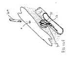
同一参照番号が複数の図を通して類似する構成要素または同一構成要素を同定している図面をここで詳細に参照すると、図1は本発明の血管ホール(穴)閉鎖デバイスの第1の実施形態の斜視図である。このデバイスは血管壁の穴を閉鎖するよう意図されたものであるが、かかる穴は、通常は、血管壁を通して血管管腔に先に挿入されたカテーテルを除去した後で形成され、血管形成術や他の介在処置を実施するためのものである。穴は患者の皮膚とその下の組織とを通って延びて、血管の外壁を通り、血管の壁を突き抜けて、更に、血管の内壁を通って血管の内部管腔と導通状態にある。本発明の閉鎖デバイスは被覆部材または補修材が血管内に配置され、血管の内壁を押圧して血流を遮断するとともに、クリップが血管壁の外側に配置されて、被覆部材を保持する。クリップは被覆部材を上方向に穴に向けて引っ張っている。Preferred embodiments of the present disclosure will now be described with reference to the accompanying drawings.
Referring now in detail to the drawings in which like reference numbers identify similar or identical components throughout the several views, FIG. 1 illustrates a first embodiment of a vascular hole closure device of the present invention. It is a perspective view. This device is intended to close a hole in the vessel wall, but such a hole is usually formed after removing the catheter previously inserted through the vessel wall into the vessel lumen, and angioplasty And other interventional procedures. The hole extends through the patient's skin and underlying tissue, passes through the outer wall of the blood vessel, penetrates the wall of the blood vessel, and is further in communication with the inner lumen of the blood vessel through the inner wall of the blood vessel. In the closure device of the present invention, the covering member or the repair material is disposed in the blood vessel, presses the inner wall of the blood vessel to block the blood flow, and the clip is disposed outside the blood vessel wall to hold the covering member. The clip is pulling the covering member upward toward the hole.
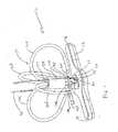
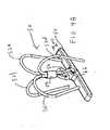
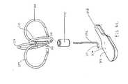
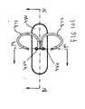
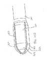
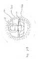
まず図1から図5を見ると、本発明の閉鎖デバイスの第1の実施形態が例示されている。ホール(穴)閉鎖デバイス10は細長い部材12と4本の脚部を有するクリップ14とを備えており、脚部は輪環38の内部に保持されたワイヤ30a、30b、30c、30dの形態であるのが好ましい。細長い部材12は血管内で穴の内側に位置するような寸法と形状に設定されており、ワイヤ30a〜30dは血管壁の外側で穴の外側に隣接して設置されるような形状になっている。 Turning first to FIGS. 1-5, a first embodiment of the closure device of the present invention is illustrated. The hole closure device 10 comprises an
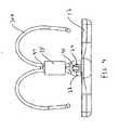
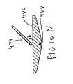
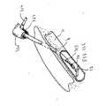
細長い部材12は血管に搬送するための細長い位置に維持されてから、血管管腔内の横断位置へと旋回する。この移動は図6および図7に例示されており、細長い部材12は一部が導入器鞘部材300から外へ配備されているが、それでもまだ、遠位端303(図6)の壁が端部領域18と嵌合することにより、長手方向軸線に沿った位置に維持されたままである。導入器鞘部材300から十分外に配備されると、細長い部材12の端部領域18も解放されるため、細長い部材は図7の横断位置へと旋回することができるようになり、この位置では、同部材は穴を通って延びる軸線に実質的に直交する。輪環38の中心が鳩目24からわずかにオフセットされて、配備時には細長い部材12がわずかに旋回できるようになり、細長い部材が引戻されて壁に押し付けられると、血管壁が細長い部材を更に旋回させて横断位置へと移動させることができるようにするのが好ましいことに留意すべきである。この移動は、閉鎖デバイス10の挿入方法についての説明に関連付けて後段でより詳細に説明される。クリップ14の脚部30a〜30eは搬送し易いように実質的に真っ直ぐな位置に維持され、解放時には、湾曲形状へと移動する。これもまた、後段で詳細に論じられる。 The
細長い部材12は血管壁の内側開口部を覆う(補修する)ように機能して、血液が流出するのを阻止する。図1および図2に例示されているように、細長い(被覆)部材は第1の端部領域16と第2の端部領域18の間に拡大領域20を設けている。長手方向軸線は長さ寸法Lを規定し、横断軸線は幅寸法を規定する。細長い部材12の両端部16、18の幅寸法w1は実質的に互いに等しいのが好ましく、また、約0.025インチから約0.035インチの範囲に入るのが好ましい。拡大領域20では、幅寸法が漸進的に増大するため、その裁断幅w2が約0.090インチから約0.125インチの範囲に入るのが好ましい。細長い部材12のこの中心の拡大領域20は他の部分よりも大きい面積を設けて、血管の内側開口部を補修(被覆)している。幅w2は開口部を効果的に覆うために内側開口部の寸法に少なくとも実質的に等しくなるのが好ましい。これ以外の寸法も考えに入れることができる。 The
細長い部材は、開口部(穴)を覆うのに十分なだけの面積を有している限りは、拡大領域なしで済ますことができるものと認識すべきである。これは図9Aに具体例として図示されているが、この場合、閉鎖デバイス50はその長さ全体にわたって幅が実質的に均一である細長い部材60を有している。この実施形態では、接続ワイヤ56は細長い部材60の突出面62に当接して、細長い部材60を傾ける(旋回させる)。残りの全ての点で、デバイス50はデバイス10と同一であるが、例えば、4本の脚部52a、52b、52c、52dは輪環59の内部に維持されて、突出面62の開口部を通って延びている接続ワイヤ56により細長い部材60に接続されている。 It should be appreciated that the elongate member can be dispensed with as long as it has an area sufficient to cover the opening (hole). This is illustrated by way of example in FIG. 9A, in which case the
細長い部材は左右非対称に構成されて、拡大領域が中心から外れた位置にきて、部材が或る角度で引っ張られた際に穴の幅が広がるのに順応するようになっていてもよい。細長い部材は、図9Bないし図9Eに関連づけて後段で論じるように、幅が狭くなった領域がそこより広い領域に隣接したパドル状の形状にされてもよい。 The elongate member may be configured asymmetrically so that the enlarged region is located off-center to accommodate the widening of the hole when the member is pulled at an angle. The elongate member may be paddle-shaped, with the narrowed region adjacent to the wider region, as will be discussed later in connection with FIGS. 9B-9E.
細長い部材はポリカーボネートまたはポリウレタンのような材料から構成されてもよいし、或いは、代替例として、グリコライド/ラクチドのような再吸収可能な材料から構成することができるが、かかる材料は或る時間の後、血管管腔の外にクリップ部のみを残して体内に再吸収される。再吸収可能材料から構成されている場合、細長い部材は、任意で、再吸収可能性が相互に異なる複数領域を設けてもよい。図11Dに一例が図示されているが、領域R1は最後に最吸収されることになり、領域R2は他の領域よりも遅い速度で再吸収され、領域R3は最初に再吸収されることになる。互いに異なる再吸収性の程度は、互いに異なる再吸収可能特性を有する異なる材料を利用することにより達成され、或いは、細長い部材の各領域の厚さを変動させることにより(厚い領域ほど再吸収に長時間を要する)達成される。 The elongate member may be composed of a material such as polycarbonate or polyurethane, or alternatively, may be composed of a resorbable material such as glycolide / lactide, but such material may be Then, it is reabsorbed into the body leaving only the clip portion outside the blood vessel lumen. When constructed from a resorbable material, the elongate member may optionally be provided with multiple regions with different resorbability. An example is shown in FIG. 11D, where region R1 will be most absorbed last, region R2 will be reabsorbed at a slower rate than other regions, and region R3 will be reabsorbed first. Become. Different degrees of resorbability can be achieved by utilizing different materials with different resorbable properties, or by varying the thickness of each region of the elongated member (thicker regions are more susceptible to resorption). Time consuming) achieved.
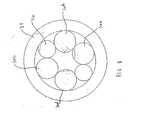
図1から図5の閉鎖デバイス10を引き続き参照すると、細長い部材12は突出面22に開口部または鳩目24が形成されている。開口部24は接続ワイヤ40を受容して、クリップ14を細長い部材12に連結する。クリップ14のクリップ脚部30a〜30dは各々が輪環38を通って延びてそれぞれに端部33a〜33dで終端する第1端と、組織に係合するように構成された第2端32a〜32dとをそれぞれ有している。図1では、端部32a〜32dは刺通しできない鈍先端である。しかし、先鋭な先端、すなわち、組織を刺通せる先端が代わりに設けられてもよいことも思量される。クリップ脚部30a〜30dは、レーザー溶着、糊、または、これ以外の固着手段により輪環38に保持される。代替例として、クリップ脚部は輪環を必要とせずに互いに(更には、接続ワイヤに)溶着され、或いは、別途付着される。 With continued reference to the closure device 10 of FIGS. 1-5, the
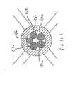
レーザー溶着や糊などの好適な手段により輪環38の内部に接続ワイヤ40が固定されるが、このワイヤは開口部24を通して領域42でループ状になる。接続ワイヤの2つの端部は参照番号44と示されている。(一方のみが図示されている)。図8は輪環38を破断した横断面図を示しており、クリップ脚部30a〜30dと接続ワイヤ40とが輪環38の内部に位置決めされているのを例示している。縫合糸45も鳩目24を通って延びており、後段で詳細に説明するように、細長い部材12を位置決めするように機能する。 A connecting
クリップ脚部30a、30b、30c、30dは、ニチノールなどの(ニッケルチタニウム合金)形状記憶材料から構成された4つの別個のワイヤ素子から構成されているのが好ましいが、その記憶された位置が図5に例示されている。使用に際し、クリップ脚部30a〜30dは搬送器具内に実質的に真っ直ぐな位置で維持され、解放されると、図3および図4に例示されているように、内向きに湾曲するように体温で加温される。クリップ脚部がそれぞれの記憶位置に戻ることができる程度は、組織の厚さと抵抗とで決まることになる。一旦内向きに湾曲してしまうと、湾曲したクリップ脚部30a〜30dは組織を把持して閉鎖デバイス10を組織内に維持する。脚部30a〜30dが内向きに湾曲すると、脚部は細長い部材12に近位方向の引っ張り力を付与し、同部材をわずかに上方向(近位方向)に引っ張って血管壁を押圧させる。脚部が集合して、血管壁の外側の組織を開口部の方へと強制的に押す。 The
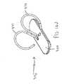
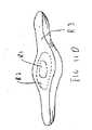
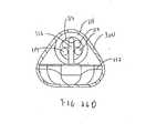
図10Aは本発明の閉鎖デバイスの代替の実施形態を例示しており、参照番号70で示されている。閉鎖デバイス70は、クリップ脚部78(そのうちの2個だけが例示されている)と輪環75のそれぞれの形状を除いて、閉鎖デバイス10に類似している。クリップ脚部78(4個設けられているのが好ましい)は矩形の断面形状を有しているワイヤから作成される。クリップ脚部78は、図示のように、細長いU字状に形成される。また、閉鎖デバイス10の円筒状輪環38の代わりに、矩形の輪環75が設けられる。細長い被覆材72や接続ワイヤ73など、上記以外のあらゆる点で、閉鎖デバイス70は閉鎖デバイス10と同一である。 FIG. 10A illustrates an alternative embodiment of the closure device of the present invention and is indicated by reference numeral 70. The closure device 70 is similar to the closure device 10 except for the respective shapes of the clip leg 78 (only two of which are illustrated) and the ring 75. The clip legs 78 (preferably four) are made from a wire having a rectangular cross-sectional shape. The
図10Bの実施形態では、閉鎖デバイス80のクリップ脚部84a〜84dが、まず、矩形(または正方形)のチューブから形成される。図示のように、チューブ86は分離されるが、これはレーザー切断によって実施されるのが好ましく、4本の湾曲脚部84a〜84dを形成するが、これらはそれぞれの閉鎖位置でC字型の形状を作る。細長い被覆部材85は閉鎖デバイス10の細長い部材12と同一である、開口部の内側を覆う(補修する)ための拡大幅領域85が設けられている。接続ワイヤ83は鳩目88を介してクリップ部を細長い部材に接続している。プラグ87は接続ワイヤ83の上にスリップ式に嵌合し、1個以上のタブ89がチューブ86の窓86aを通してスナップ式に嵌合し、細長い部材82をチューブ86に接続している。 In the embodiment of FIG. 10B, the clip legs 84a-84d of the closure device 80 are first formed from a rectangular (or square) tube. As shown, the tube 86 is separated, but this is preferably performed by laser cutting, forming four curved legs 84a-84d, which are C-shaped in their closed positions. Make a shape. The elongated covering member 85 is identical to the
本件に開示されている別な実施形態は輪環部に取付けるための保持用のタブを有していてもよいものと認識するべきである。 It should be appreciated that other embodiments disclosed herein may have retaining tabs for attachment to the annulus.
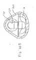
図10Cから図10Eの実施形態では、閉鎖デバイス270は2本のクリップ脚部272a、272bが、ニチノールのような形状記憶材料の1枚の金属材シートまたは1本の金属材片から形成される。代替例として、2本を越える脚部、例えば、4本の脚部が金属材から形成されてもよい。クリップ脚部272a、272bは、図示のようにC字型に湾曲しているが、中心領域274で分離して、互いに反対方向に湾曲する。中央領域においてこのように分離してクリップ脚部を形成することは、矩形チューブをレーザー切断することにより実施されるのが好ましい。中心領域274には幅を減じた領域276が設けられている。接続端は湾曲させられて、細長い部材(補修材)280に取付けるためのフックまたはタブ278を形成する。接続端にも幅を減じた部分279が設けられて、細長い部材280の内部にはタブ278を機械的に固定させるためのショルダーを形成している。 In the embodiment of FIGS. 10C-10E, the closure device 270 has two clip legs 272a, 272b formed from one metal sheet or one metal piece of shape memory material, such as Nitinol. . As an alternative, more than two legs, for example four legs, may be formed from a metal material. The clip legs 272a and 272b are curved in a C shape as shown in the figure, but are separated in the
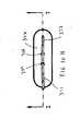
細長い部材280は、図示のように、細長い互いに平行な側壁282a、282b、および、これら側壁282a、282bに接続している弧状の端部壁284a、284bと一緒に楕円状になっている。細長い部材280のこのような構成では、端部以外の他の部分では、幅zが実質的に均一である。横断スロットすなわち開口部285はタブ278を受容するような形状にされて、細長い部材280にクリップ脚部を固定させるようになっている。固定具合を向上させるために、製造途中で細長い部材は加熱されてタブの周囲で溶融するのが好ましい。これ以外の固定プロセスも考えられる。 The
2本のクリップ脚部が細長い部材に関して図10Cとは90度位相が異なって位置決めされた状態で、閉鎖デバイス280が形成されてもよいと思量される。すなわち、細長い部材のスロットは長手方向軸線に沿って配向され、タブは横断方向に向けられ(そうでなければ、脚部が長手方向軸線に沿ったタブに関して90度の角度で捻られる)、そのため、クリップ脚部272a、272bが図10Cにおけるような長手方向軸線に実質的に平行な方向よりはむしろ、細長い部材の長手方向軸線に実質的に直交する方向に湾曲することになる。このような配向は血管の長さに沿ったクリップのプロファイルを低減し、血管に沿って多数のクリップを互いにより近接して設置することができるようになる。細長い部材に関してクリップ脚部をこのように配向させる一例が、後段で説明するように、図10Jの実施形態に例示されている。 It is contemplated that the
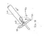
図10Fから図10Iは輪環の無いクリップ閉鎖設計の別な実施形態を例示している。この実施形態では、閉鎖デバイス370の細長い部材(補修材)380は、楕円形状にされてているという点と、その端部385、387を除いて実質的に均一な幅yになっているという点で、図10Cの実施形態の細長い部材280に類似した形状になっている。細長い部材は厚さがkである中心部が設けられており、この中心部では端部よりも厚みがある。この結果、各端部は、中央部、すなわち、クリップ部に取付けられる領域よりも速い速度で再吸収されるため、クリップの取付けがより長時間残存する。細長い部材380はその上面388には2個の開口部384、386が、その下面390には長手方向軸線方向に延びる溝389が設けられており、これらが一緒にU字型のチャネルを形成して、クリップの受容に備えている。 FIGS. 10F-10I illustrate another embodiment of a clip closure design without annulus. In this embodiment, the elongated member (repair material) 380 of the
クリップ部は、図示のように、丸いワイヤを曲げて、互いに180度離れた位置に置かれた2本のクリップ脚部371、372を形成している。クリップ脚部371、372は細長い部材380の長手方向軸線に実質的に平行な方向に外向きに湾曲している。クリップ脚部371は先端371a、湾曲部371b、および、真っ直ぐな部分371cを有している。クリップ脚部372は先端部372a、第1の湾曲部372b、第2の湾曲部372c、および、真っ直ぐな部分372dを有している。クリップ脚部371、372の真っ直ぐな部分371c、372dは長手方向軸線方向の延びた部分373によって接合される。この部分373は細長い部材380の下面390の溝389の内部に載置されている。真っ直ぐな部分371c、372dは細長い部材380の開口部384、386を通って延びている。クリップ部を細長い部材380に固定させる具合を向上させるために、製造途中に細長い部材を加熱してクリップの周囲のプラスチックを溶融させるようにしてもよい。クリップを外科手術部位に搬送する間、クリップの脚部は図10Fで分かるように細長い部材380の頂面で左方向に折曲げられるが、湾曲部372cがこのような折り曲げを容易にしている。 As shown in the drawing, the clip portion is formed by bending a round wire and forming two
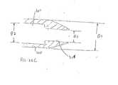
図10Jから図10Nの代替の実施形態では、クリップ脚部は細長い部材(補修材)480の長手方向軸線に実質的に直交する方向に湾曲するような配向にされるが、これは補修材380に形状と厚さが類似している。閉鎖デバイス470のクリップ脚部471、472は各々がそれぞれの先端部471a、472a、湾曲部471b、472b、真っ直ぐな部分471c、472c、分岐脚部471d、472d、および、横断部474により接続されている下位の真っ直ぐな部分471e、472eを有している。先端部471a、471bおよび湾曲部などの各脚部の一部は細長い部材480の幅寸法を超過していることに留意すべきである。クリップ脚部は、開口部484、486および横断溝488によって形成された細長い部材480のU字型チャネルの中へと延びている。クリップ脚部を横断方向に設置した結果、移植時には、クリップが血管に沿って占有する空間は狭くなり、そのため、再吸収可能な細長い部材が再吸収された後のような後の機会に、また別な複数のクリップを一緒により近接させて設置することができるようになる。クリップ部は、図示のように、細長い部材480に対して45度のような鋭角bを成して(他の角度も考えられる)設置することができるため、血管に挿入されると、細長い部材は血管壁に実質的に平行になって現れる。この角度を達成するために、下位の真っ直ぐな部分471e、472eが細長い部材480の上表面平面に実質的に直交する平面に延在し、真っ直ぐな部分471c、472cは同平面に対して鋭角を成して延在する。 In the alternative embodiment of FIGS. 10J-10N, the clip legs are oriented to curve in a direction substantially perpendicular to the longitudinal axis of the elongated member (repair material) 480, which is the
クリップ脚部の真っ直ぐな部分が横並びに図示されているが、真っ直ぐな部分は上下に重畳されてもよいことも思量される。 Although straight portions of the clip legs are shown side by side, it is contemplated that the straight portions may be superimposed one above the other.
搬送中は、クリップ脚部471、472は細長い部材の上に折り曲げられるため、クリップの搬送プロファイルを低減する。組立て中は、クリップは事前装填することができるため、脚部は互いに交差し、それにより、細長い部材の配備配向の抑制するための安定性を向上させることができる。図10の別な実施形態では、細長い部材は再吸収可能な材料から構成されているのが好ましく、クリップ脚部は形状記憶材料から構成されるのが好ましいが、これら以外の材料も考えられる。 During transport, the
図11Aは閉鎖デバイスの別な代替の実施形態の斜視図である。この実施形態では、閉鎖デバイス90は、図1の実施形態におけるように、4本の脚部94を有している(そのうちの2本のみが図示されている)。図1および図14に例示されているような鳩目を通って延びる縫合糸の代わりに、縫合糸97が接続ワイヤ96のループ95に接続されている。すなわち、接続ワイヤ96は一端で細長い部材92の鳩目93を通ってループ状となり、反対端で縫合糸ループ95を受容する。この態様で、縫合糸が近位方向に引っ張られると、細長い部材(およびクリップ)が近位方向に引っ張られる。接続ワイヤ96はレーザー溶着、糊による固着、或いは、上記以外の好適な手段により輪環98の内部に付着されるのが好ましい。接続ワイヤ96は細長い部材を横断位置に偏倚させるために利用することができる。 FIG. 11A is a perspective view of another alternative embodiment of a closure device. In this embodiment, the
図11Bの実施形態では、閉鎖デバイス110の接続ワイヤ116は細長い部材112の中に埋設され、例えば、同部材の中に挿入成形される。これにより部材112のプロファイルは低減するが、これは、図11Aの実施形態におけるような突出面(突起部)が排除されているせいである。また、接続ワイヤ116は形状記憶金属のような材料から作成され、これは実質的に真っ直ぐな位置にくるように設計され、或いは、代替例として、45度のような角度を設けた位置にくるように設計される。この構成は細長い部材112を横断位置に偏倚させる。そうでなければ、デバイス110の脚部114(2本のみが図示されている)、接続ワイヤ116に付着された縫合糸117などはデバイス90のものと同一である。 In the embodiment of FIG. 11B, the connecting wire 116 of the closure device 110 is embedded in the
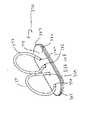
図9Bから図9Eは閉鎖デバイスの代替の実施形態を例示しており、同デバイスは参照番号140と示されており、挿入成形、機械的接続、または、上記以外の好適な手段により可撓性の接続ワイヤ146が細長い被覆部材142に取付けられている。図示のように、接続ワイヤ146は、任意でニチノールのような形状記憶金属から構成されるが、接続部材142の中心を外れた位置に設置されて、同部材を横断位置へと偏倚させるとともに、長手方向軸線に沿った位置に接続部材142を移動させるのを容易にして、血管への搬送に備えている。接続ワイヤ146の近位端は縫合糸手段により輪環148に取付けられる。図1の実施形態におけるような4本のクリップ脚部144が設けられる。クリップ脚部144は図示のようなフック型の先端部145を有していてもよく、これらが輪環148の内側に配置されるとともに同輪環に係合し、輪環内部での固定を促進する。 9B-9E illustrate an alternative embodiment of the closure device, which is designated as
細長い被覆部材142は、細長い領域142aと幅が狭くなった領域142bを設けたパドル状になっているため、そのプロファイルを低減しており、閉鎖デバイス140を設置した後に血管内に残される材料の全体量が低減される。幅が狭くなった領域142bは、任意で、拡大領域142aを設けた遷移部から始まって漸進的に先細りとなっていてもよい。 The
好ましい製造方法では、輪環148、クリップ脚部144、および、接続ワイヤ146は一緒にレーザー溶着される。接続ワイヤ146は、タグ端147を設けており、後で図示の配向で被覆部材142に接続される。この好ましい取付け方法では、被覆部材142は長手方向軸線スロットを有しており、界面の隆起部(図示せず)が接続ワイヤ142のタグ端147を受容するような寸法に設定されている。吸収可能な糊、または、吸収不可能な糊を任意で付与して、タグ端147の取付けを向上させたり、封止部を設けたりすることができる。 In a preferred manufacturing method, the ring 148,
図11Cは閉鎖デバイスのまた別な代替の実施形態を例示しており、同デバイスは参照番号130で示されている。閉鎖デバイス130は、矩形断面のワイヤから形成された平坦面をそれぞれに有しているクリップ脚部134a〜134dを有しており、形状記憶金属から構成されているのが好ましい。接続ストラップ136、或いは代替例として、図11Aのワイヤ96のような接続ワイヤが細長い部材132の鳩目133を通って延びている。縫合糸137はストラップ136を通ってループ状にされ、細長い部材132を引っ張って穴の内側開口部に押し付けるようにしている。クリップ脚部134a〜134dは、輪環138のそれぞれの窓135を通して延びる脚部の各々にそれぞれのタブ139を嵌合させることにより、輪環138の内部に維持される。 FIG. 11C illustrates yet another alternative embodiment of the closure device, which is indicated by
4個の別個のワイヤ脚部が互いに約90度離されている本件記載の閉鎖デバイスでは、それより少数の脚部、例えば、2本の脚部が互いに約180度間隔を離され、3本の脚部が互いに約120度間隔を離され、或いは、4本を越える脚部がデバイス維持機能を達成するために設けられてもよいことも考えられる。同様に、2本の脚部を有する実施例を修正することにより、より少数の脚部またはより多数の脚部を設けることもできる。4個のクリップを設けた実施例では、空間を節約するために、すなわち、搬送器具や導入器鞘部材の内部に設置するための寸法を最小限に抑えるために、脚部は互いに関して左右対称に間隔を設ける必要はないが、少なくとも互いに対向する脚部は互いから約180度離すようにするのが好ましい(例えば、図16Cを参照のこと)ものと認識するべきである。 In the closure device of the present description in which four separate wire legs are separated from each other by approximately 90 degrees, a smaller number of legs, for example, two legs are spaced from each other by approximately 180 degrees, It is contemplated that the legs may be approximately 120 degrees apart from each other, or more than four legs may be provided to achieve the device maintenance function. Similarly, fewer or more legs can be provided by modifying the embodiment with two legs. In the embodiment with four clips, the legs are symmetrical with respect to each other in order to save space, i.e. to minimize the dimensions for installation inside the transport device or introducer sheath member. However, it should be recognized that at least the opposing legs are preferably about 180 degrees apart from each other (see, eg, FIG. 16C).
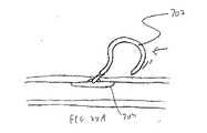
図28から図30は、細長い部材を維持して組織および細長い部材に近位方向の力を及ぼすために利用される1個のクリップ脚部の一例を示している。図28Aおよび図28Bにおいて、湾曲したクリップ脚部702は、搬送器具703から外に配備されると、図示のように内向きに湾曲して、組織を把持し、内側血管壁を押圧した状態で細長い部材704を固着させる。図29および図30では、クリップ脚部740は、細長い部材744に直接接続されて、搬送器具742(図30)の内側の実質的に真っ直ぐな位置に維持され、配備時には、それ自体の周囲で湾曲し、図29Bに例示されているように、バネ状の素子を形成する。クリップ脚部740はコイル状になって、細長い部材744の上で持ち上がり、血管内にクリップ脚部を維持する。 FIGS. 28-30 illustrate an example of a single clip leg utilized to maintain the elongate member and exert a proximal force on the tissue and elongate member. In FIGS. 28A and 28B, when the
本件記載されている実施形態の各々で、鈍先端部または鋭利な先端部がクリップ脚部に設けられて、それぞれの把持機能を実施することができる。形状記憶金属から構成されるのが好ましいが、クリップ脚部は、代替例として、形状記憶プラスチック、ステンレス鋼、再吸収可能材料、或いは、上記以外の材料から構成されてもよい。本件に例示されたクリップ脚部は、組織の抵抗なしに形成されると、それぞれの記憶された位置などのような十分な形態を表すことも認識すべきである。組織に設置されると、クリップ脚部は必ずしも例示したような十分な程度まで移動(湾曲)するわけではない。脚部のそれぞれの湾曲の程度は、患者の組織のタイプと厚さで大部分が決まる。 In each of the embodiments described herein, a blunt tip or a sharp tip is provided on the clip leg to perform the respective gripping function. Although preferably constructed from shape memory metal, the clip legs may alternatively be constructed from shape memory plastic, stainless steel, resorbable materials, or other materials. It should also be appreciated that the clip legs illustrated in this case represent sufficient features such as their stored locations, etc., when formed without tissue resistance. When placed in tissue, the clip legs do not necessarily move (curve) to a sufficient extent as illustrated. The degree of curvature of each leg is largely determined by the type and thickness of the patient's tissue.
ここで本発明の閉鎖デバイスの設置に目を向けると、図12Aないし図12Eは第1の挿入方法を例示している。例示の方法は閉鎖デバイス10の設置を示しているが、本件記載の別な閉鎖デバイスが同じような態様で挿入されてもよいものと解釈するべきである。 Turning now to the installation of the closure device of the present invention, FIGS. 12A-12E illustrate a first insertion method. Although the exemplary method shows installation of the closure device 10, it should be construed that other closure devices described herein may be inserted in a similar manner.
図12Aに例示されているように、拡張器304は導入器鞘部材300に挿通され、ガイドワイヤ302の上を伝って血管管腔に挿入される。鞘部材と拡張器304は皮膚の開口部aを通って延び、組織路を更に通って血管Vに行き、血管壁の外側開口部bを通って血管壁wの穴を更に通り、血管壁の内側の内部開口部cを通って血管管腔の中へと延びる(図12Fも参照のこと)ことに留意するべきである。 As illustrated in FIG. 12A, the
次いで、ガイドワイヤ302および拡張器304が引き出され、図12Bに例示されているように、閉鎖付与(搬送)器具310が鞘部材300により血管管腔内に挿入される。細長い部材12は搬送器具310の遠位方向に延びて、導入器鞘部材300の壁により長手方向軸線に沿った位置に維持され、クリップ脚部は、低温の生理食塩水の灌注により搬送器具内でマルテンサイト状態で実質的に真っ直ぐな位置に維持される。 The
搬送器具310は導入器鞘部材300を通って遠位先端部303を越えて前進させられるため、細長い部材12は導入器鞘部材300の壁の拘束の外にあって、血管壁の内側開口部から十分に間隔を設けて血管管腔内に延びる。これにより、細長い部材12が旋回運動を行う十分な余地が設けられる。細長い部材12が壁の拘束から解放されると、図12Cに例示されているような横断位置に向けて旋回することが可能となる。 The
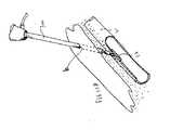
次いで、鞘部材300および搬送器具310は、細長い部材が血管壁wの内側開口部cを押圧して載置されるまで、単体として近位方向に引っ張られる。(鞘部材300と器具310は任意で一緒に嵌合させられる(ロックされる)ため、両部材は単体として移動させることができるものと思量される。)細長い部材12の鳩目24を通って延びる縫合糸45(図14および図15を参照のこと)は搬送器具310に取付けられており、搬送器具を近位方向に引っ張ると縫合糸45を引っ張り、従って細長い部材12を近位方向に引っ張ることになる。細長い部材12は近位方向に引っ張られて、拡張領域20が内側開口部cの上に広がって流体の流出を阻止することで、補修材のような態様で開口部を覆う。血管壁は十分な横断位置まで細長い部材を更に旋回させる点に留意するべきである。 Next, the
一旦細長い部材12が載置されてしまうと、クリップ脚部に押し付けたプッシャー(図示せず)を遠位方向に移動させることにより閉鎖デバイスが搬送デバイス310から外へ更に排出されることで、クリップ14を搬送器具310から外へ強制的に出すため、クリップ脚部30a〜30dは体温により加温され、それぞれの記憶された形状に向けて移動する。図12Eは、細長い部材12と一緒に適所にある閉鎖デバイス10が血管Vの内側の内側開口部cに当接して開口部を覆い(補修し)、維持脚部30a〜30dが下向きに湾曲し、好ましくはわずかに内向きに湾曲して組織路と穴に向かい、組織に係合して細長い部材12に近位方向(上向き)の力を付与しているのを例示している。組織はまた、湾曲したクリップ脚部30a〜30dにより強制されて、血管壁の外側の穴および組織路に向かわせられる。図12Eも、導入器鞘部材300(および搬送デバイス310)が患者の体内から引き出されているのを例示している。縫合糸は搬送デバイス310と一緒に引き出される。 Once the
一実施形態では、十分な負荷(閾量を超過している)が縫合糸に置かれると、縫合糸は自動的に裂けて、閉鎖デバイスを搬送器具から分離するように設計されていることに留意するべきである。 In one embodiment, the suture is designed to automatically tear and separate the closure device from the delivery instrument when sufficient load (exceeding the threshold amount) is placed on the suture. It should be noted.
代替の挿入法では、搬送器具310が導入器鞘部材300に挿通されて、細長い部材12が導入器鞘部材300の壁の拘束内に留まると、細長い部材は、搬送器具の前進よりもむしろ、プッシャーによって排除される。すなわち、搬送器具の内部のプッシャーが作動されて閉鎖デバイスを前進させるため、細長い部材12が遠位方向に移動させられて、導入器鞘部材の壁の拘束の外に出る。細長い部材12のこのような配備位置では、クリップ脚部30a〜30dはそれでもまだ搬送器具310の内部に留まり、未だに配備されないままである。任意で、搬送器具310は近位端で鞘部材30にロックすることもできる。細長い部材12の上に引戻して血管の内側開口部を覆った後で、クリップ脚部30a〜30dは搬送器具300を近位方向に移動させてクリップ脚部を露出させることにより配備され、或いは、更にプッシャーを作動させて搬送器具からクリップ脚部を前進させることで配備される。 In an alternative insertion method, when the
図13Aないし図13Eは、本発明の閉鎖デバイスの代替の挿入方法を例示している。本件開示の別な閉鎖デバイスも搬送器具320と一緒に搬送することができるものと理解するべきである。図13Aから図13Eの搬送方法は、閉鎖デバイスを遠位方向に前進させて旋回運動のために細長い部材を解放する代わりに、導入器鞘部材300が搬送器具320に関して後退させられるということを例外として、図12Aから図12Eの方法と同じである。 13A-13E illustrate an alternative insertion method for the closure device of the present invention. It should be understood that other closure devices of the present disclosure can also be transported with the transport device 320. The delivery method of FIGS. 13A-13E is the exception that the
より具体的には、この方法では、拡張器(図13A)がガイドワイヤ上を伝って図12Aと同じ態様で導入される。図13Aは、図13Bの位置に対応して鞘部材が更に深く血管内を前進させられた際の部分導入を例示していることに留意するべきである。導入器鞘部材300は血管に挿入されるが、図13Bに例示されているように、図12の方法におけるよりも血管内を更に深く挿入されることにも注目するべきである。すなわち、導入器鞘部材300の遠位先端部303は、細長い部材12を血管内に解放するのが望ましい位置まで移動させられる。一旦適所に置かれると、導入器鞘部材300は搬送器具320に関して後退させられ、同時に、チューブ材コネクタ314が搬送器具320のスロット322に受容される。鞘部材300が後退させられると、細長い部材312が図13Cに例示されているように露出され、従って、細長い部材12は導入器鞘部材300の壁によってもはや保持されることがないので、その横断位置に向けて旋回することができるようになる。細長い部材12を近位方向に引っ張ってクリップを解放する残りの工程(図13Dおよび図13Eに例示されている)は、図12Dおよび図12Eに関して前述した工程と同じである。 More specifically, in this method, a dilator (FIG. 13A) is introduced over the guide wire in the same manner as FIG. 12A. It should be noted that FIG. 13A illustrates partial introduction as the sheath member is advanced deeper into the blood vessel corresponding to the position of FIG. 13B. It should also be noted that the
本件記載の搬送方法の拡張形状から収縮形状までの間の運動を可能にするために、上述のように、クリップ脚部30a〜30dはニチノールすなわちニッケルチタニウム合金のような形状記憶金属材から作成されるのが好ましい。クリップ脚部に搬送器具320の管腔を通過させて血管に入れるのを容易にするために、低温の生理食塩水が搬送器具320内と搬送器具320内部で収縮位置にある脚部30a〜30dの周囲とに注入される。この形状記憶材料はオーステナイト状態では剛性を顕著に示し、マルテンサイト状態ではより一層の可撓性を示す。低温生理食塩水は温度依存型のワイヤ30a〜30dが搬送器具内でマルテンサイト状態にある場合には、各ワイヤを比較的軟らかい状態に維持する。これは搬送器具320からのワイヤ30a〜30dの搬出を容易にするが、逆に、ワイヤ30a〜30dの剛性が維持され、すなわち、オーステンサイト状態である場合には、ワイヤ30a〜30dと器具320の内面との間に摩擦接触が別に生じる。止水栓301(例えば、図24Aを参照のこと)は生理食塩水の流れを抑制することができる。 In order to allow movement between the expanded shape and the contracted shape of the transfer method described herein, as described above, the
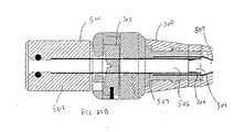
図23Aは、導入器鞘部材300と一緒に利用されて、より大きい寸法の搬送器具とより大きい寸法の細長い部材12とを導入器鞘部材300を通して挿入することができるようにする挿入チューブ500を例示している。挿入チューブ500はヘッド部502と、
ヘッド部502から延びている細長い管状部504とを有している。管腔506はチューブ500を通って延びている。図23Bに例示されているように、挿入チューブ500は鞘部材300の狭くなった管腔領域307の近位で終端する。チューブ500は領域509におけるより小さい内部管腔径まで段階的に径を減じてゆく。FIG. 23A illustrates an
And an elongated
挿入管500の管腔506は約0.096インチの直径を有しているのが好ましく、約0.088インチ(領域509)まで段階的に径を減じることができるのが好ましい。導入器鞘部材300の管腔309は直径が約0.125インチであるのが好ましく、狭められた管腔領域307は直径D2が約0.087インチであるのが好ましく、約0.079インチの直径D3まで段階的に径を減じられるのが好ましい(図26C)。導入器鞘部材300の外径D1は約0.105インチで、挿入チューブ500の管状部504の外径は約0.114インチであるのが好ましい。搬送器具の外径は約0.079インチであるのが好ましい。細長い部材12は長さ寸法が約0.313インチ(8mm)であるのが好ましい。(先の寸法は具体例として提示されているのであって、上記以外の寸法も思量されることに留意すべきである。) The
挿入チューブ500を使用しているせいで、細長い部材12は搬送器具310の外側に設置され、チューブ500の管腔506と鞘部材300の管腔309、307、305の中に給送される。図24から図26に例示されているように、初期挿入されると、閉鎖デバイス(輪環38、細長い部材12など)が鞘部材壁を偏向させずに鞘部材300の拘束領域内に適合する(図24B)。図25Aに例示されているように、搬送器具310が導入器鞘部材500に更に挿入されると、鞘部材壁は図25Bに例示されているように偏向され、弾性限界を超えて偏向されると変形するが、それは先端部の径の方が小さいせいである。図26Aに例示されているように十分に挿入されると図26Bに例示されているように壁の弾性限界を超えて壁を更に偏向(変形)させる。挿入チューブ500を使用しない場合は、細長い部材12は搬送器具310の内部に維持されなければならず、これには、より大きい径の搬送器具310か、より小さい(長さ)細長い部材12のいずれかが必要となる。 Due to the use of the
図26Dは、図11Bの閉鎖デバイスが導入器鞘部材300の内部に配置されて、図26Aの位置に対応して壁を偏向させているのを例示している。 FIG. 26D illustrates the closure device of FIG. 11B being disposed within the
図16Aないし図16Cは本発明の閉鎖デバイスの代替の実施形態を例示しているが、これは、スロットを設けたチューブを利用して閉鎖デバイスを後退させたり解放したりする。閉鎖デバイス150は、図1の閉鎖デバイスの細長い部材12およびクリップ脚部30a〜30dと同じである細長い部材152およびクリップ脚部154a〜154dを備えている。閉鎖デバイス150は図1の輪環38と同じ輪環158も備えている。接続ワイヤ156は、図11Bと同じ態様で細長い部材152に挿入成形されているが、デバイスのクリップ部を細長い部材152に接続している。図16Cの断面図は、クリップ脚部154a〜154dと接続ワイヤ156がどのように輪環158の内側でその外周に沿って載置され、製造を容易にしているかを例示している。 16A-16C illustrate an alternative embodiment of the closure device of the present invention, which utilizes a slotted tube to retract and release the closure device. The
搬送器具のスロットを設けたチューブ160は、一連の複数のスロット162を有しており、この数は例えば4個であって一連の可撓性のフィンガー164を設けているが、輪環158の上に着脱自在に載置されて、閉鎖デバイスを保持している。この干渉嵌合のせいで、搬送器具161に固定的に搭載されているスロットを設けたチューブ160が搬送器具161の近位方向への移動に伴って近位方向に引っ張られると、輪環158と、従って、閉鎖デバイス150が近位方向に引っ張られて細長い部材152を血管の内壁に押圧して据付け、穴の内側開口部を覆う。十分な負荷がスロットを設けたチューブ160に置かれると、フィンガー164が外方向に屈曲して輪環158の上を滑動し、搬送器具のスロットを設けたチューブ160から閉鎖デバイス150を解放する。 The
代替の実施形態では(図示せず)、解放チューブはスロットを設ける代わりにクリンプ加工またはスエージ加工を施した先端部を設け、これが輪環よりわずかに遠位位置に設置される。この先端部は可撓性に富み、チューブに十分な負荷を置くと、先端部が屈曲して輪環の上に乗り上げ、閉鎖デバイスを解放する。更に、内表面に複数の陥凹を設けて輪環上にチューブを維持する支援を行うこともできるが、これにより輪環の解放もできるようになっている。 In an alternative embodiment (not shown), instead of providing a slot, the release tube is provided with a crimped or swaged tip that is placed slightly distal from the annulus. The tip is flexible and when a sufficient load is placed on the tube, the tip bends and rides on the annulus, releasing the closure device. Furthermore, it is possible to provide a plurality of recesses on the inner surface to assist in maintaining the tube on the ring, but this also allows the ring to be released.
図16Dの代替の実施形態では、スロットを設けたチューブの代わりに、1対の顎部181、182が搬送器具180に固着される。顎部181、182は閉鎖デバイス170の輪環178を把持する。閉鎖デバイス170は図16Aのデバイス160と実質的に同一であり、細長い部材172、接続ワイヤ176、輪環178、および、4本のクリップ脚部174(明瞭にするために2本の端部のみが図示されている)を有している。十分な負荷が顎部181、182に置かれると、顎部が開いて輪環178から滑って脱落し、閉鎖デバイス170を搬送器具の顎部から解放する。 In the alternative embodiment of FIG. 16D, instead of a slotted tube, a pair of jaws 181, 182 are secured to the
図21および図22の実施形態では、搬送器具190の1対の顎部191は1本以上のクリップ脚部30を把持する。アリゲータクランプなどの顎部191はバネ偏倚により開位置に移動し、また、導入器鞘部材300の壁により図22に例示されているような閉位置に維持される。搬送器具が導入器鞘部材300の内部で遠位先端部302を越えて前進させられると、顎部191が開位置に移動して、クリップ脚部と閉鎖デバイスを解放する。 In the embodiment of FIGS. 21 and 22, the pair of jaws 191 of the transport device 190 grips one or
図31から図36は、閉鎖デバイスを設置するための搬送器具のまた別な代替の実施形態を例示している。図9Bの閉鎖デバイス140の設置を目的として説明してきたが、本件記載の別な閉鎖デバイスが類似した態様で設置されてもよい。 Figures 31 to 36 illustrate yet another alternative embodiment of a delivery device for installing a closure device. Although described for purposes of installing the
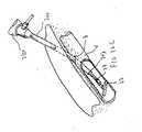
まず図31を参照すると、搬送器具800は収納器801を備えており、これはウイングを設けた把持器802、収納器801に関して軸線方向に移動可能で閉鎖デバイス140を前進させるプランジャー804、および、プランジャー804を後退位置と前進位置のそれぞれに固定するためのロック窓806a、806bを有している。細長い外側チューブ805は収納器801から延びており、内部に閉鎖デバイス140を受容するような寸法に設定されている。プランジャー804にはプッシャー806が接続されており、これは4個の長手方向軸線に沿ったスロット807を設けて(図33および図36を参照のこと)、各々が搬送器具800の内部の真っ直ぐな位置にクリップ脚部を受容するようにしている。プッシャー806の遠位端は、図35に例示されているように、保持輪環148の近位でクリップ脚部144の領域に当接する。 Referring first to FIG. 31, the delivery device 800 includes a
プランジャー804が前進させられると、プッシャー806も遠位方向に移動させられ、閉鎖デバイス140を強制的に前方に付勢するため、細長い部材142は血管内に前進し、上述のオフセット接続ワイヤの偏倚力に支援されてその横断位置へ移動する。プランジャー804の前進により可撓性のフィンガー809もロック窓806aに嵌合している状態から移動して、対向位置にある窓806bに嵌合し、プランジャー804とプッシャー806を前進位置に維持することに留意するべきである。フィンガー809の角度を設けた表面809aがプランジャー804の遠位方向移動を可能にする一方で、真っ直ぐな表面809bが窓806a、806bから外れて近位方向に移動するのを阻止する(図32を参照のこと)点にも留意するべきである。 As the
搬送器具800は導入器鞘部材により血管に挿入されるが、同部材は図31および図35で参照番号900と示されている。導入器鞘部材900は、従来の拡張器または搬送器具800のいずれかを受容する近位開口部902を設けたハブ906を有している。鞘部材チューブ907はハブ906から延びて、側壁の遠位端位置に開口部904を有している。遠位端は領域909で先細りにされ、拡張器と一緒に封止を設ける。鞘部材チューブ907の近位端は領域912で末広がり状にされ、導入器鞘部材900を通して搬送器具800が挿入されると、搬送器具800の外側チューブ805の滑らかな移動が可能となるが、これは、閉鎖デバイス140が適所にある場合には、外側チューブ805が外方向に脹らんでいるせいである。ひずみ解放器910が鞘部材チューブ907の一部を包囲している。 The delivery device 800 is inserted into the blood vessel by an introducer sheath member, which is indicated by reference number 900 in FIGS. Introducer sheath member 900 has a
鞘部材900のハブ906は45度のサイドアーム913を有しており、これは、チューブ材915、ひずみ解放器914、拡張組立体920を搭載するための雄ルアー916を備えている。従来のクランプ918はチューブ材915に設置される。拡張組立体920の遠位端は雄ルアー916上にネジ留めされ、拡張組立体の近位端は、後段で説明される注射器を搭載するためのネジ筋を設けた取付け組立体922を備えている。 The
ハブ906は近位端に弁組立体を更に備えており、同組立体はスペーサリング930、スリット配置を設けた円筒状の弁素子932、および、鞘部材キャップ934から構成される。鞘部材キャップ934は、拡張器(図示せず)および搬送器具800をスナップ式嵌合配置により受容および搭載する寸法に設定された開口部936を備えている。遠位鞘部材キャップ938がハブ906の遠位端に取付けられている。輪環810は搬送器具800の収納器801に取付けられ、鞘部材キャップ934の開口部936の内部に先端部812のスナップが嵌合させられる。 The
搬送器具800を用いて閉鎖デバイス140を設置する工程をここで説明する。まず、血管に導入器鞘部材90を設置するために、生理食塩水のような流体で満たした注射器950は拡張組立体920の近位ネジの上にネジ止めされる。使用者が注射器プランジャー952を沈降させようとすると、従来の拡張器(図示せず)が鞘部材キャップ934の中にスナップ式に嵌合した状態で、導入器鞘部材900はガイドワイヤの上を伝って血管壁に向かって組織路を通して挿入される。鞘部材900がまだ組織路の内部にある間に、非常に少量の生理食塩水が側面開口部904を通して注射器950から排出される。このように、プランジャー952の移動はほとんどない。しかし、導入器鞘部材900が組織路を通して前進させられ、血管壁を通って血管管腔に入ると、生理食塩水が側面開口部904から流出するが(拡張器と鞘部材900の内壁の間の隙間を流動した後に)、このようにして、プランジャー952をより素早く沈降させることができる。これにより、導入器鞘部材900が血管内に所望するとおりに設置され、閉鎖デバイスは、搬送器具800を介して鞘部材900に挿通された際に血管管腔に確実に挿入されるという、視覚による感触と触覚による感覚が得られる。 The process of installing the
導入器鞘部材900が血管内の適所に置かれると、拡張器が取り出される。注射器950は低温の生理食塩水で満たされ、或いは、拡張組立体920から取外され、低温の生理食塩水を満たした別な注射器がネジ922に取付けられる。この低温の生理食塩水は搬送中に閉鎖デバイス140に供与され、他の実施形態に関連して先に説明した低温のマーテンサイト状態に脚部144と接続ワイヤ146を維持する。 Once the introducer sheath member 900 is in place in the blood vessel, the dilator is removed. Syringe 950 is filled with cold saline or removed from expansion assembly 920 and another syringe filled with cold saline is attached to screw 922. This cold saline is provided to the
拡張器を取り出した後、搬送器具800は導入器鞘部材900を通して挿入する準備ができる。閉鎖デバイス140は図35に例示されているように搬送器具800に設置され、この時、クリップ脚部142はプッシャー806の長手方向軸線に沿ったスロットに包含される。細長い部材142は外側チューブ805の拘束領域内に包含される。外側チューブ805は、導入器鞘部材900に挿通されて同部材にスナップ式に嵌合すると、図示のように導入器鞘部材900の遠位先端部の近位に留まる。次に、プランジャー804が沈降してプッシャー806を遠位方向に移動させて(フィンガー809が窓806bに設置されるまで)閉鎖デバイス140を前進させるため、細長い部材142は外側チューブ805の拘束領域を越えて移動し、更に、導入器鞘部材900の遠位先端部を越えて移動する。チューブ805と鞘部材900の拘束領域の外側に出てしまうと、細長い部材142は図36に例示されているような横断位置へと旋回する。 After removing the dilator, the delivery device 800 is ready for insertion through the introducer sheath member 900. The
次いで、鞘部材900と搬送器具800が近位方向に引っ張られ、細長い部材142を引っ張って血管壁を押圧する。細長い部材は、血管壁と当接してしまうと、鞘部材900と搬送器具800の近位方向移動に抗して反力を付与する。その結果、鞘部材900と器具800のこれに続く近位方向運動が鞘部材900と器具800の拘束領域からクリップ脚部144を解放し、クリップ脚部144は体温で加温されると、それぞれの湾曲した記憶された形状位置に戻る。次に、鞘部材900と搬送器具800が体内から取り出される。 The sheath member 900 and delivery device 800 are then pulled proximally, pulling the
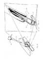
図18ないし図20は、血管内に細長い部材を位置決めし直すのを容易にする搬送器具の代替の実施形態を例示している。すなわち、これらの実施形態では、搬送(閉鎖付与)器具は、当接表面が細長い部材の両側面の一方に係合するような形状になった突出遠位先端部を有している。細長い部材の頂面に抗して当接面を押圧することで、細長い部材は強制的に長手方向軸線に沿った位置に旋回して戻り、望ましいようであれば、血管から引き出される。これは、クリップを配備する前に体内にクリップを位置決めし直すのをより容易にできるようにする。 18-20 illustrate an alternative embodiment of a delivery device that facilitates repositioning the elongate member within the blood vessel. That is, in these embodiments, the delivery (closure imparting) device has a protruding distal tip shaped such that the abutment surface engages one of the sides of the elongated member. By pressing the abutment surface against the top surface of the elongate member, the elongate member is forced back to a position along the longitudinal axis and, if desired, pulled out of the blood vessel. This makes it easier to reposition the clip in the body before deploying the clip.
より具体的には、図18では、器具400の突出先端部402は細長い部材92の上面99に当接している。この図は器具300を含む図11Aの閉鎖デバイス90の使用を例示している。図19では、閉鎖デバイス10’は図1(および図15)の閉鎖デバイス10に類似しているが、但し、接続ワイヤ42’のための分離した開口部を例外とする。細長い部材12’は旋回可能で、器具410の突出先端部412によって仮想線で例示された位置まで戻る。 More specifically, in FIG. 18, the protruding tip 402 of the instrument 400 is in contact with the upper surface 99 of the elongated member 92. This figure illustrates the use of the
図20では、細長い部材102は閉鎖デバイス100のオフセット縫合糸104により横断位置へと偏倚させられる。細長い部材は器具の突出先端部により旋回させることができる。 In FIG. 20, the
図17Aおよび図17Bは細長い部材の変形例を示している。閉鎖デバイス120は茸型のサドル121を有しており、これが血管の穴の内側開口部を覆うように血管の内側壁に当接するように機能する。サドル121は2個の側面125が下方向に湾曲した円形外周部を有している。茎部124から延びるクリップ脚部122a、122b、122c、122dは上述のクリップ脚部と同じ態様で機能する。クリップ脚部122a〜122dは刺通し先端部124a〜124dを設けた状態で例示されているが、非刺通し先端部が設けられても良い。この閉鎖デバイス210は2000年9月12日に出願された、本件譲受人に譲渡された特許出願番号第09/659,648号により詳細に記載されているが、この出願の全内容は引用されて本件の一部を成している。 17A and 17B show a modification of the elongated member. The
図27および図28は、クリップ脚部を細長い部材に接続する処理に対する異なるアプローチを利用して、本発明の閉鎖部材の代替の実施形態を例示している。この実施例が前述の実施形態と異なっているのは、この実施例が、製造を簡略化し、また、デバイスを簡略化するために或る構成要素を排除して、閉鎖部材の各部を取付けることと、細長い部材を偏倚させることの両方を目的として利用するために1個の要素しか利用する必要がないようにしているせいである。より具体的には、閉鎖デバイス600は、図1の実施形態の脚部30に類似している4本の脚部602を備えており、その類似点は、それらが記憶された湾曲形状を備えているということである。チューブ604は細長い部材603に溶着されるのが好ましいが、他の手段によって挿入成形され、或いは、取付けされてもよい。チューブ604は螺旋状に切断されて可撓性を供与するとともに、チューブの屈曲を許容している。チューブ604の近位端606の内部にクリップ脚部602が延びており、これら脚部は領域608でチューブ604を通して溶着される。上記以外の取付け手段も利用される。チューブ604の近位部606はクリップ脚部602に取付ける領域に剛性を供与するように切断されているわけではない。螺旋状チューブはそれ自体幾つかの機能を果たすが、クリップ脚部602を撓み性のある態様で細長い部材603に接続し、クリップ脚部を維持し、細長い部材603を偏倚させて横断位置に移動させるという機能がある。 FIGS. 27 and 28 illustrate an alternative embodiment of the closure member of the present invention utilizing a different approach to the process of connecting the clip leg to the elongated member. This example differs from the previous embodiment because it simplifies manufacturing and eliminates certain components and attaches parts of the closure member to simplify the device. And only one element is required to be used for both the purpose of biasing the elongated member. More specifically, the closure device 600 includes four
上記説明は多く特徴を含んでいるが、そのような特徴は開示の範囲を制限するものと解釈されるべきではなく、好ましい実施形態の具体例にすぎないと見なされるべきである。例えば、細長い部材(補修材)の前述の実施形態のいずれも、再吸収可能な材料または最吸収不可能な材料のいずれから作成されてもよい。更に、前述の実施形態では、クリップ部を図10Jにあるような細長い部材に対して位置決めするのに、鋭角を設けてもよいし、それ以外の角度を設けてもよい。更に、前述の実施形態のクリップ脚部を設置するにあたり、図10Fにあるように長手方向軸線に沿った配向にしてもよいし、図10Jにあるような横断配向にしてもよいし、或いは、細長い部材に関して別な角度の配向にしてもよいし、勿論同様に、細長い部材の上面の平面に対して別な角度の配向にしてもよい。また、本件に開示されている細長い部材の異なる形状を、本願に記載された実施形態に開示された多様なクリップ形状と併用することもできる。好適な材料を利用すれば、クリップ部および細長い部材は単体構造にすることもできる。添付の特許請求の範囲の各請求項により限定されるような開示の範囲および精神の範囲に入る可能な変形例は、当業者なら他にも多数想起することができるであろう。 Although the above description includes many features, such features should not be construed as limiting the scope of the disclosure, but should be considered merely as examples of preferred embodiments. For example, any of the foregoing embodiments of elongate members (repair materials) may be made from either a resorbable material or a non-absorbable material. Furthermore, in the above-described embodiment, an acute angle may be provided to position the clip portion with respect to the elongated member as shown in FIG. 10J, or an angle other than that may be provided. Further, in installing the clip leg of the above-described embodiment, it may be oriented along the longitudinal axis as shown in FIG. 10F, may be oriented transversely as shown in FIG. 10J, or The angled orientation of the elongated member may be different, and of course, the angled orientation of the upper surface of the elongated member may be different. Also, the different shapes of the elongate members disclosed herein can be used in conjunction with the various clip shapes disclosed in the embodiments described herein. If a suitable material is used, the clip portion and the elongated member can be a unitary structure. Those skilled in the art will envision many other possible variations that fall within the scope and spirit of the disclosure as defined by the appended claims.
Claims (54)
Translated fromJapanese長手方向軸線を有し、穴の内側開口部に接して血管の内側に設置可能な細長い部材を備えており、細長い部材は、穴を通って流体が流出するのを阻止するために、穴の内側開口部の寸法に少なくとも実質的に等しい寸法を有し、
該デバイスは、
細長い部材を適所に保持するのを支援するために血管の外側に設置可能な少なくとも2本の湾曲した脚部を備えている、デバイス。A device for closing a hole in a blood vessel, the hole having an outer opening in an outer region of the blood vessel wall and an inner opening in an inner region of the blood vessel wall,
An elongate member having a longitudinal axis and capable of being placed inside the blood vessel against the inner opening of the hole, the elongate member configured to prevent fluid from flowing through the hole; Having a dimension at least substantially equal to the dimension of the inner opening;
The device
A device comprising at least two curved legs that can be placed outside of a blood vessel to assist in holding the elongated member in place.
穴被覆部材と、被覆部材に接続された少なくとも1本の脚部を有する閉鎖デバイスを備え、被覆部材と少なくとも1本の脚部は挿入位置と配備位置との間で可動であり、
挿入位置では、被覆部材は穴の長手方向軸線に実質的に平行であり、配備位置では、被覆部材は穴の第1の側では穴の長手方向軸線に実質的に垂直であり、挿入位置では、少なくとも1本の脚部は実質的に真っ直ぐな位置にあり、配備位置では、脚部は湾曲形状を有しており、穴の第2の側にある組織を把持するように構成されている、装置。A device for closing a hole in a blood vessel, the device comprising:
A closure device having a hole covering member and at least one leg connected to the covering member, the covering member and the at least one leg being movable between an insertion position and a deployed position;
In the insertion position, the covering member is substantially parallel to the longitudinal axis of the hole; in the deployed position, the covering member is substantially perpendicular to the longitudinal axis of the hole on the first side of the hole; The at least one leg is in a substantially straight position, and in the deployed position, the leg has a curved shape and is configured to grasp tissue on the second side of the hole. ,apparatus.
a)穴被覆部材と維持部材とを有している閉鎖デバイスを備えており、穴被覆部材は血管の内側に設置可能であるとともに、血管壁の穴の内側を被覆するような寸法に設定されており、維持部材は血管の外側の組織に係合する複数の湾曲した脚部を有しており、
該システムは、
b)閉鎖デバイスを搬送する搬送器具を更に備えており、搬送器具は閉鎖デバイスと着脱自在に係合可能な保持部材を有しており、閉鎖デバイスを位置決めするとともに、閉鎖デバイスを解放するようにした、システム。A system for closing a hole in a vessel wall, the system comprising:
a) a closure device having a hole covering member and a retaining member, the hole covering member being installable inside the vessel and dimensioned to cover the inside of the vessel wall hole; The maintenance member has a plurality of curved legs that engage tissue outside the blood vessel;
The system
b) further comprising a transport device for transporting the closure device, the transport device having a retaining member removably engageable with the closure device, for positioning the closure device and for releasing the closure device; System.
a)穴被覆部材と維持部材とを有している閉鎖デバイスを備えており、穴被覆部材は血管の内側に設置可能であるとともに、血管壁の穴の内側を被覆するような寸法に設定されており、維持部材は血管の外側の組織に係合する複数の湾曲した脚部を有しており、
該システムは、
b)閉鎖デバイスを搬送する搬送器具を更に備えており、搬送器具は外側チューブと、外側チューブの内部に滑動自在に配置されるプッシャーとを有しており、プッシャーは維持部材に係合して外側チューブから被覆部材を外へ前進させる、システム。A system for closing a hole in a vessel wall, the system comprising:
a) a closure device having a hole covering member and a retaining member, the hole covering member being installable inside the vessel and dimensioned to cover the inside of the vessel wall hole; The maintenance member has a plurality of curved legs that engage tissue outside the blood vessel;
The system
b) further comprising a transport device for transporting the closure device, the transport device having an outer tube and a pusher slidably disposed within the outer tube, the pusher engaging the retaining member; A system for advancing the covering member out of the outer tube.
細長い部材と複数の維持脚部とを有している閉鎖デバイスを設ける工程と、
血管内に細長い部材を配備して、穴の第1側すなわち内側を覆う工程と、
血管壁の外側に維持脚部を配備して、脚部が湾曲形状を取った結果、穴の第2側すなわち外側の組織を把持する工程とを含んでいる、方法。A method of closing a hole in a blood vessel wall, the method comprising:
Providing a closure device having an elongated member and a plurality of maintenance legs;
Deploying an elongate member within the blood vessel to cover the first or inner side of the hole;
Deploying maintenance legs outside the vessel wall and grasping the tissue on the second or outer side of the hole as a result of the legs taking a curved shape.
Applications Claiming Priority (4)
| Application Number | Priority Date | Filing Date | Title |
|---|---|---|---|
| US35552602P | 2002-02-06 | 2002-02-06 | |
| US10/163,142US7341595B2 (en) | 1999-09-13 | 2002-06-05 | Vascular hole closure device |
| US10/345,533US7267679B2 (en) | 1999-09-13 | 2003-01-16 | Vascular hole closure device |
| PCT/US2003/002934WO2003065898A2 (en) | 2002-02-06 | 2003-01-31 | Vascular hole closure device |
Publications (3)
| Publication Number | Publication Date |
|---|---|
| JP2005516659Atrue JP2005516659A (en) | 2005-06-09 |
| JP2005516659A5 JP2005516659A5 (en) | 2006-03-09 |
| JP4335690B2 JP4335690B2 (en) | 2009-09-30 |
Family
ID=27739051
Family Applications (1)
| Application Number | Title | Priority Date | Filing Date |
|---|---|---|---|
| JP2003565330AExpired - Fee RelatedJP4335690B2 (en) | 2002-02-06 | 2003-01-31 | Blood vessel hole closure device |
Country Status (6)
| Country | Link |
|---|---|
| US (2) | US7267679B2 (en) |
| EP (1) | EP1480567B1 (en) |
| JP (1) | JP4335690B2 (en) |
| AU (1) | AU2003210767B2 (en) |
| CA (1) | CA2473451C (en) |
| WO (1) | WO2003065898A2 (en) |
Cited By (2)
| Publication number | Priority date | Publication date | Assignee | Title |
|---|---|---|---|---|
| JP2009521266A (en)* | 2005-12-23 | 2009-06-04 | コーディス・コーポレイション | System for closing vascular wounds |
| JP2020022875A (en)* | 2016-08-12 | 2020-02-13 | エッセンシャル メディカル インコーポレイテッド | Vascular closure device with tamper lock assembly |
Families Citing this family (642)
| Publication number | Priority date | Publication date | Assignee | Title |
|---|---|---|---|---|
| AU7373700A (en)* | 1999-09-13 | 2001-04-17 | Rex Medical, Lp | Vascular closure |
| US7662161B2 (en)* | 1999-09-13 | 2010-02-16 | Rex Medical, L.P | Vascular hole closure device |
| US7341595B2 (en)* | 1999-09-13 | 2008-03-11 | Rex Medical, L.P | Vascular hole closure device |
| US6391048B1 (en) | 2000-01-05 | 2002-05-21 | Integrated Vascular Systems, Inc. | Integrated vascular device with puncture site closure component and sealant and methods of use |
| US9579091B2 (en) | 2000-01-05 | 2017-02-28 | Integrated Vascular Systems, Inc. | Closure system and methods of use |
| US6461364B1 (en) | 2000-01-05 | 2002-10-08 | Integrated Vascular Systems, Inc. | Vascular sheath with bioabsorbable puncture site closure apparatus and methods of use |
| US8758400B2 (en) | 2000-01-05 | 2014-06-24 | Integrated Vascular Systems, Inc. | Closure system and methods of use |
| US7842068B2 (en) | 2000-12-07 | 2010-11-30 | Integrated Vascular Systems, Inc. | Apparatus and methods for providing tactile feedback while delivering a closure device |
| DE60144328D1 (en) | 2000-09-08 | 2011-05-12 | Abbott Vascular Inc | Surgical clamp |
| US6626918B1 (en) | 2000-10-06 | 2003-09-30 | Medical Technology Group | Apparatus and methods for positioning a vascular sheath |
| US6623510B2 (en) | 2000-12-07 | 2003-09-23 | Integrated Vascular Systems, Inc. | Closure device and methods for making and using them |
| US7806904B2 (en) | 2000-12-07 | 2010-10-05 | Integrated Vascular Systems, Inc. | Closure device |
| US6695867B2 (en) | 2002-02-21 | 2004-02-24 | Integrated Vascular Systems, Inc. | Plunger apparatus and methods for delivering a closure device |
| US7905900B2 (en) | 2003-01-30 | 2011-03-15 | Integrated Vascular Systems, Inc. | Clip applier and methods of use |
| US7211101B2 (en) | 2000-12-07 | 2007-05-01 | Abbott Vascular Devices | Methods for manufacturing a clip and clip |
| US8690910B2 (en) | 2000-12-07 | 2014-04-08 | Integrated Vascular Systems, Inc. | Closure device and methods for making and using them |
| IES20010547A2 (en) | 2001-06-07 | 2002-12-11 | Christy Cummins | Surgical Staple |
| US7288105B2 (en)* | 2001-08-01 | 2007-10-30 | Ev3 Endovascular, Inc. | Tissue opening occluder |
| IES20030424A2 (en) | 2002-06-04 | 2003-12-10 | Robert Stevenson | Blood vessel closure clip and delivery device |
| US8821534B2 (en) | 2010-12-06 | 2014-09-02 | Integrated Vascular Systems, Inc. | Clip applier having improved hemostasis and methods of use |
| US7857828B2 (en) | 2003-01-30 | 2010-12-28 | Integrated Vascular Systems, Inc. | Clip applier and methods of use |
| US8758398B2 (en) | 2006-09-08 | 2014-06-24 | Integrated Vascular Systems, Inc. | Apparatus and method for delivering a closure element |
| US8202293B2 (en) | 2003-01-30 | 2012-06-19 | Integrated Vascular Systems, Inc. | Clip applier and methods of use |
| US8398656B2 (en) | 2003-01-30 | 2013-03-19 | Integrated Vascular Systems, Inc. | Clip applier and methods of use |
| US8905937B2 (en) | 2009-02-26 | 2014-12-09 | Integrated Vascular Systems, Inc. | Methods and apparatus for locating a surface of a body lumen |
| US20040176800A1 (en)* | 2003-03-07 | 2004-09-09 | Paraschac Joseph Francis | Barbed closure device |
| US9060770B2 (en) | 2003-05-20 | 2015-06-23 | Ethicon Endo-Surgery, Inc. | Robotically-driven surgical instrument with E-beam driver |
| US20070084897A1 (en) | 2003-05-20 | 2007-04-19 | Shelton Frederick E Iv | Articulating surgical stapling instrument incorporating a two-piece e-beam firing mechanism |
| EP1667586A1 (en) | 2003-09-15 | 2006-06-14 | Abbott Laboratories | Suture locking device and methods |
| ES2293357T3 (en)* | 2003-10-24 | 2008-03-16 | Ev3 Endovascular, Inc. | CLOSURE SYSTEM OF A PERMEABLE OVAL FORM. |
| US20050096696A1 (en)* | 2003-11-04 | 2005-05-05 | Forsberg Andrew T. | Arteriotomy closure device with anti-roll anchor |
| CA2551531C (en)* | 2003-12-26 | 2015-02-24 | Terumo Kabushiki Kaisha | Tissue closure and tissue closing device |
| US8882786B2 (en) | 2004-02-17 | 2014-11-11 | Lawrence Livermore National Security, Llc. | System for closure of a physical anomaly |
| IES20040368A2 (en) | 2004-05-25 | 2005-11-30 | James E Coleman | Surgical stapler |
| US11890012B2 (en) | 2004-07-28 | 2024-02-06 | Cilag Gmbh International | Staple cartridge comprising cartridge body and attached support |
| US9072535B2 (en) | 2011-05-27 | 2015-07-07 | Ethicon Endo-Surgery, Inc. | Surgical stapling instruments with rotatable staple deployment arrangements |
| US11998198B2 (en) | 2004-07-28 | 2024-06-04 | Cilag Gmbh International | Surgical stapling instrument incorporating a two-piece E-beam firing mechanism |
| US8215531B2 (en) | 2004-07-28 | 2012-07-10 | Ethicon Endo-Surgery, Inc. | Surgical stapling instrument having a medical substance dispenser |
| JP4366306B2 (en)* | 2004-12-17 | 2009-11-18 | テルモ株式会社 | In vivo tissue closure device and in vivo tissue closure device |
| WO2006115689A1 (en) | 2005-04-22 | 2006-11-02 | Rex Medical, L.P. | Closure device for left atrial appendage |
| US8926633B2 (en) | 2005-06-24 | 2015-01-06 | Abbott Laboratories | Apparatus and method for delivering a closure element |
| US20080312686A1 (en)* | 2005-07-01 | 2008-12-18 | Abbott Laboratories | Antimicrobial closure element and closure element applier |
| US8313497B2 (en) | 2005-07-01 | 2012-11-20 | Abbott Laboratories | Clip applier and methods of use |
| US8800838B2 (en) | 2005-08-31 | 2014-08-12 | Ethicon Endo-Surgery, Inc. | Robotically-controlled cable-based surgical end effectors |
| US9237891B2 (en) | 2005-08-31 | 2016-01-19 | Ethicon Endo-Surgery, Inc. | Robotically-controlled surgical stapling devices that produce formed staples having different lengths |
| US10159482B2 (en) | 2005-08-31 | 2018-12-25 | Ethicon Llc | Fastener cartridge assembly comprising a fixed anvil and different staple heights |
| US11484312B2 (en) | 2005-08-31 | 2022-11-01 | Cilag Gmbh International | Staple cartridge comprising a staple driver arrangement |
| US7934630B2 (en) | 2005-08-31 | 2011-05-03 | Ethicon Endo-Surgery, Inc. | Staple cartridges for forming staples having differing formed staple heights |
| US7673781B2 (en) | 2005-08-31 | 2010-03-09 | Ethicon Endo-Surgery, Inc. | Surgical stapling device with staple driver that supports multiple wire diameter staples |
| US7669746B2 (en) | 2005-08-31 | 2010-03-02 | Ethicon Endo-Surgery, Inc. | Staple cartridges for forming staples having differing formed staple heights |
| US11246590B2 (en) | 2005-08-31 | 2022-02-15 | Cilag Gmbh International | Staple cartridge including staple drivers having different unfired heights |
| US8545530B2 (en) | 2005-10-19 | 2013-10-01 | Pulsar Vascular, Inc. | Implantable aneurysm closure systems and methods |
| EP1951129B1 (en) | 2005-10-19 | 2012-11-21 | Pulsar Vascular, Inc. | Methods and systems for endovascularly clipping and repairing lumen and tissue defects |
| US20070106317A1 (en) | 2005-11-09 | 2007-05-10 | Shelton Frederick E Iv | Hydraulically and electrically actuated articulation joints for surgical instruments |
| US8161977B2 (en) | 2006-01-31 | 2012-04-24 | Ethicon Endo-Surgery, Inc. | Accessing data stored in a memory of a surgical instrument |
| US20120292367A1 (en) | 2006-01-31 | 2012-11-22 | Ethicon Endo-Surgery, Inc. | Robotically-controlled end effector |
| US9861359B2 (en) | 2006-01-31 | 2018-01-09 | Ethicon Llc | Powered surgical instruments with firing system lockout arrangements |
| GB2447400B (en)* | 2006-01-31 | 2011-11-02 | Cook Biotech Inc | Fistula grafts and related methods and systems for treating fistulae |
| US7753904B2 (en) | 2006-01-31 | 2010-07-13 | Ethicon Endo-Surgery, Inc. | Endoscopic surgical instrument with a handle that can articulate with respect to the shaft |
| US8763879B2 (en) | 2006-01-31 | 2014-07-01 | Ethicon Endo-Surgery, Inc. | Accessing data stored in a memory of surgical instrument |
| US11278279B2 (en) | 2006-01-31 | 2022-03-22 | Cilag Gmbh International | Surgical instrument assembly |
| US8820603B2 (en) | 2006-01-31 | 2014-09-02 | Ethicon Endo-Surgery, Inc. | Accessing data stored in a memory of a surgical instrument |
| US20110295295A1 (en) | 2006-01-31 | 2011-12-01 | Ethicon Endo-Surgery, Inc. | Robotically-controlled surgical instrument having recording capabilities |
| US8186555B2 (en) | 2006-01-31 | 2012-05-29 | Ethicon Endo-Surgery, Inc. | Motor-driven surgical cutting and fastening instrument with mechanical closure system |
| US11793518B2 (en) | 2006-01-31 | 2023-10-24 | Cilag Gmbh International | Powered surgical instruments with firing system lockout arrangements |
| US8708213B2 (en) | 2006-01-31 | 2014-04-29 | Ethicon Endo-Surgery, Inc. | Surgical instrument having a feedback system |
| US7845537B2 (en) | 2006-01-31 | 2010-12-07 | Ethicon Endo-Surgery, Inc. | Surgical instrument having recording capabilities |
| US11224427B2 (en) | 2006-01-31 | 2022-01-18 | Cilag Gmbh International | Surgical stapling system including a console and retraction assembly |
| US20110024477A1 (en) | 2009-02-06 | 2011-02-03 | Hall Steven G | Driven Surgical Stapler Improvements |
| US8992422B2 (en) | 2006-03-23 | 2015-03-31 | Ethicon Endo-Surgery, Inc. | Robotically-controlled endoscopic accessory channel |
| US8236010B2 (en) | 2006-03-23 | 2012-08-07 | Ethicon Endo-Surgery, Inc. | Surgical fastener and cutter with mimicking end effector |
| US8808310B2 (en) | 2006-04-20 | 2014-08-19 | Integrated Vascular Systems, Inc. | Resettable clip applier and reset tools |
| WO2007146887A2 (en)* | 2006-06-09 | 2007-12-21 | Cordis Corporation | Single disc intraluminal patent foramen ovale closure device |
| US8322455B2 (en) | 2006-06-27 | 2012-12-04 | Ethicon Endo-Surgery, Inc. | Manually driven surgical cutting and fastening instrument |
| US8556930B2 (en) | 2006-06-28 | 2013-10-15 | Abbott Laboratories | Vessel closure device |
| US8529597B2 (en) | 2006-08-09 | 2013-09-10 | Coherex Medical, Inc. | Devices for reducing the size of an internal tissue opening |
| US10130359B2 (en) | 2006-09-29 | 2018-11-20 | Ethicon Llc | Method for forming a staple |
| US10568652B2 (en) | 2006-09-29 | 2020-02-25 | Ethicon Llc | Surgical staples having attached drivers of different heights and stapling instruments for deploying the same |
| US7506791B2 (en) | 2006-09-29 | 2009-03-24 | Ethicon Endo-Surgery, Inc. | Surgical stapling instrument with mechanical mechanism for limiting maximum tissue compression |
| US11980366B2 (en) | 2006-10-03 | 2024-05-14 | Cilag Gmbh International | Surgical instrument |
| WO2008043044A2 (en)* | 2006-10-04 | 2008-04-10 | Ndo Surgical, Inc. | Devices and methods for endoluminal gastric restriction tissue manipulation, and drug delivery |
| US8652120B2 (en) | 2007-01-10 | 2014-02-18 | Ethicon Endo-Surgery, Inc. | Surgical instrument with wireless communication between control unit and sensor transponders |
| US8684253B2 (en) | 2007-01-10 | 2014-04-01 | Ethicon Endo-Surgery, Inc. | Surgical instrument with wireless communication between a control unit of a robotic system and remote sensor |
| US8459520B2 (en) | 2007-01-10 | 2013-06-11 | Ethicon Endo-Surgery, Inc. | Surgical instrument with wireless communication between control unit and remote sensor |
| US11291441B2 (en) | 2007-01-10 | 2022-04-05 | Cilag Gmbh International | Surgical instrument with wireless communication between control unit and remote sensor |
| US8632535B2 (en) | 2007-01-10 | 2014-01-21 | Ethicon Endo-Surgery, Inc. | Interlock and surgical instrument including same |
| US11039836B2 (en) | 2007-01-11 | 2021-06-22 | Cilag Gmbh International | Staple cartridge for use with a surgical stapling instrument |
| US20080169333A1 (en) | 2007-01-11 | 2008-07-17 | Shelton Frederick E | Surgical stapler end effector with tapered distal end |
| WO2008094691A2 (en)* | 2007-02-01 | 2008-08-07 | Cook Incorporated | Closure device and method for occluding a bodily passageway |
| JP2010517641A (en)* | 2007-02-05 | 2010-05-27 | ボストン サイエンティフィック サイムド,インコーポレイテッド | Device and method for closing a vascular opening using a permanent implant |
| US7673782B2 (en) | 2007-03-15 | 2010-03-09 | Ethicon Endo-Surgery, Inc. | Surgical stapling instrument having a releasable buttress material |
| US8893946B2 (en) | 2007-03-28 | 2014-11-25 | Ethicon Endo-Surgery, Inc. | Laparoscopic tissue thickness and clamp load measuring devices |
| US11564682B2 (en) | 2007-06-04 | 2023-01-31 | Cilag Gmbh International | Surgical stapler device |
| US8534528B2 (en) | 2007-06-04 | 2013-09-17 | Ethicon Endo-Surgery, Inc. | Surgical instrument having a multiple rate directional switching mechanism |
| US7905380B2 (en) | 2007-06-04 | 2011-03-15 | Ethicon Endo-Surgery, Inc. | Surgical instrument having a multiple rate directional switching mechanism |
| US7832408B2 (en) | 2007-06-04 | 2010-11-16 | Ethicon Endo-Surgery, Inc. | Surgical instrument having a directional switching mechanism |
| US8931682B2 (en) | 2007-06-04 | 2015-01-13 | Ethicon Endo-Surgery, Inc. | Robotically-controlled shaft based rotary drive systems for surgical instruments |
| US9610070B2 (en) | 2007-06-15 | 2017-04-04 | Vivasure Medical Limited | Closure device |
| US8408439B2 (en) | 2007-06-22 | 2013-04-02 | Ethicon Endo-Surgery, Inc. | Surgical stapling instrument with an articulatable end effector |
| US7753245B2 (en) | 2007-06-22 | 2010-07-13 | Ethicon Endo-Surgery, Inc. | Surgical stapling instruments |
| US8226681B2 (en) | 2007-06-25 | 2012-07-24 | Abbott Laboratories | Methods, devices, and apparatus for managing access through tissue |
| US11849941B2 (en) | 2007-06-29 | 2023-12-26 | Cilag Gmbh International | Staple cartridge having staple cavities extending at a transverse angle relative to a longitudinal cartridge axis |
| EP2166954A1 (en) | 2007-07-13 | 2010-03-31 | Rex Medical, L.P. | Vascular hole closure device |
| US9456816B2 (en) | 2007-09-12 | 2016-10-04 | Transluminal Technologies, Llc | Closure device, deployment apparatus, and method of deploying a closure device |
| JP5426553B2 (en)* | 2007-09-12 | 2014-02-26 | トランスルミナル テクノロジーズ リミテッド ライアビリティー カンパニー | Closure device, placement device, and method of placing a closure device |
| US8876861B2 (en) | 2007-09-12 | 2014-11-04 | Transluminal Technologies, Inc. | Closure device, deployment apparatus, and method of deploying a closure device |
| US7875054B2 (en) | 2007-10-01 | 2011-01-25 | Boston Scientific Scimed, Inc. | Connective tissue closure device and method |
| US8893947B2 (en) | 2007-12-17 | 2014-11-25 | Abbott Laboratories | Clip applier and methods of use |
| US20090157101A1 (en) | 2007-12-17 | 2009-06-18 | Abbott Laboratories | Tissue closure system and methods of use |
| US7841502B2 (en) | 2007-12-18 | 2010-11-30 | Abbott Laboratories | Modular clip applier |
| US8561870B2 (en) | 2008-02-13 | 2013-10-22 | Ethicon Endo-Surgery, Inc. | Surgical stapling instrument |
| US8584919B2 (en) | 2008-02-14 | 2013-11-19 | Ethicon Endo-Sugery, Inc. | Surgical stapling apparatus with load-sensitive firing mechanism |
| US8622274B2 (en) | 2008-02-14 | 2014-01-07 | Ethicon Endo-Surgery, Inc. | Motorized cutting and fastening instrument having control circuit for optimizing battery usage |
| US8752749B2 (en) | 2008-02-14 | 2014-06-17 | Ethicon Endo-Surgery, Inc. | Robotically-controlled disposable motor-driven loading unit |
| US11986183B2 (en) | 2008-02-14 | 2024-05-21 | Cilag Gmbh International | Surgical cutting and fastening instrument comprising a plurality of sensors to measure an electrical parameter |
| US8636736B2 (en) | 2008-02-14 | 2014-01-28 | Ethicon Endo-Surgery, Inc. | Motorized surgical cutting and fastening instrument |
| US8758391B2 (en) | 2008-02-14 | 2014-06-24 | Ethicon Endo-Surgery, Inc. | Interchangeable tools for surgical instruments |
| US8573465B2 (en) | 2008-02-14 | 2013-11-05 | Ethicon Endo-Surgery, Inc. | Robotically-controlled surgical end effector system with rotary actuated closure systems |
| JP5410110B2 (en) | 2008-02-14 | 2014-02-05 | エシコン・エンド−サージェリィ・インコーポレイテッド | Surgical cutting / fixing instrument with RF electrode |
| US7866527B2 (en) | 2008-02-14 | 2011-01-11 | Ethicon Endo-Surgery, Inc. | Surgical stapling apparatus with interlockable firing system |
| US7819298B2 (en) | 2008-02-14 | 2010-10-26 | Ethicon Endo-Surgery, Inc. | Surgical stapling apparatus with control features operable with one hand |
| US8459525B2 (en) | 2008-02-14 | 2013-06-11 | Ethicon Endo-Sugery, Inc. | Motorized surgical cutting and fastening instrument having a magnetic drive train torque limiting device |
| US9179912B2 (en) | 2008-02-14 | 2015-11-10 | Ethicon Endo-Surgery, Inc. | Robotically-controlled motorized surgical cutting and fastening instrument |
| US8657174B2 (en) | 2008-02-14 | 2014-02-25 | Ethicon Endo-Surgery, Inc. | Motorized surgical cutting and fastening instrument having handle based power source |
| US7793812B2 (en) | 2008-02-14 | 2010-09-14 | Ethicon Endo-Surgery, Inc. | Disposable motor-driven loading unit for use with a surgical cutting and stapling apparatus |
| US8070772B2 (en) | 2008-02-15 | 2011-12-06 | Rex Medical, L.P. | Vascular hole closure device |
| US8920462B2 (en) | 2008-02-15 | 2014-12-30 | Rex Medical, L.P. | Vascular hole closure device |
| US8920463B2 (en) | 2008-02-15 | 2014-12-30 | Rex Medical, L.P. | Vascular hole closure device |
| US9585657B2 (en) | 2008-02-15 | 2017-03-07 | Ethicon Endo-Surgery, Llc | Actuator for releasing a layer of material from a surgical end effector |
| US20090206141A1 (en) | 2008-02-15 | 2009-08-20 | Ethicon Endo-Surgery, Inc. | Buttress material having an activatable adhesive |
| US20110029013A1 (en) | 2008-02-15 | 2011-02-03 | Mcguckin James F | Vascular Hole Closure Device |
| US11272927B2 (en) | 2008-02-15 | 2022-03-15 | Cilag Gmbh International | Layer arrangements for surgical staple cartridges |
| US8491629B2 (en) | 2008-02-15 | 2013-07-23 | Rex Medical | Vascular hole closure delivery device |
| US9226738B2 (en) | 2008-02-15 | 2016-01-05 | Rex Medical, L.P. | Vascular hole closure delivery device |
| US20090216267A1 (en)* | 2008-02-26 | 2009-08-27 | Boston Scientific Scimed, Inc. | Closure device with rapidly dissolving anchor |
| US9282965B2 (en) | 2008-05-16 | 2016-03-15 | Abbott Laboratories | Apparatus and methods for engaging tissue |
| WO2010028314A1 (en) | 2008-09-05 | 2010-03-11 | Pulsar Vascular, Inc. | Systems and methods for supporting or occluding a physiological opening or cavity |
| EP2163205A1 (en)* | 2008-09-11 | 2010-03-17 | Beat Dr. Wicky | Device for closing wounds, particularly wounds caused by the insertion of a trocar into the abdominal wall |
| US7954686B2 (en) | 2008-09-19 | 2011-06-07 | Ethicon Endo-Surgery, Inc. | Surgical stapler with apparatus for adjusting staple height |
| PL3476312T3 (en) | 2008-09-19 | 2024-03-11 | Ethicon Llc | Surgical stapler with apparatus for adjusting staple height |
| US9050083B2 (en) | 2008-09-23 | 2015-06-09 | Ethicon Endo-Surgery, Inc. | Motorized surgical instrument |
| US11648005B2 (en) | 2008-09-23 | 2023-05-16 | Cilag Gmbh International | Robotically-controlled motorized surgical instrument with an end effector |
| US9005230B2 (en) | 2008-09-23 | 2015-04-14 | Ethicon Endo-Surgery, Inc. | Motorized surgical instrument |
| US8210411B2 (en) | 2008-09-23 | 2012-07-03 | Ethicon Endo-Surgery, Inc. | Motor-driven surgical cutting instrument |
| US9386983B2 (en) | 2008-09-23 | 2016-07-12 | Ethicon Endo-Surgery, Llc | Robotically-controlled motorized surgical instrument |
| US8608045B2 (en) | 2008-10-10 | 2013-12-17 | Ethicon Endo-Sugery, Inc. | Powered surgical cutting and stapling apparatus with manually retractable firing system |
| US8398676B2 (en) | 2008-10-30 | 2013-03-19 | Abbott Vascular Inc. | Closure device |
| US8323312B2 (en) | 2008-12-22 | 2012-12-04 | Abbott Laboratories | Closure device |
| US8858594B2 (en) | 2008-12-22 | 2014-10-14 | Abbott Laboratories | Curved closure device |
| US9414820B2 (en) | 2009-01-09 | 2016-08-16 | Abbott Vascular Inc. | Closure devices, systems, and methods |
| US9486191B2 (en) | 2009-01-09 | 2016-11-08 | Abbott Vascular, Inc. | Closure devices |
| US9173644B2 (en) | 2009-01-09 | 2015-11-03 | Abbott Vascular Inc. | Closure devices, systems, and methods |
| US9089311B2 (en) | 2009-01-09 | 2015-07-28 | Abbott Vascular Inc. | Vessel closure devices and methods |
| US20100179589A1 (en) | 2009-01-09 | 2010-07-15 | Abbott Vascular Inc. | Rapidly eroding anchor |
| US20100185234A1 (en) | 2009-01-16 | 2010-07-22 | Abbott Vascular Inc. | Closure devices, systems, and methods |
| US8397971B2 (en) | 2009-02-05 | 2013-03-19 | Ethicon Endo-Surgery, Inc. | Sterilizable surgical instrument |
| US8414577B2 (en) | 2009-02-05 | 2013-04-09 | Ethicon Endo-Surgery, Inc. | Surgical instruments and components for use in sterile environments |
| US8517239B2 (en) | 2009-02-05 | 2013-08-27 | Ethicon Endo-Surgery, Inc. | Surgical stapling instrument comprising a magnetic element driver |
| US8444036B2 (en) | 2009-02-06 | 2013-05-21 | Ethicon Endo-Surgery, Inc. | Motor driven surgical fastener device with mechanisms for adjusting a tissue gap within the end effector |
| US8453907B2 (en) | 2009-02-06 | 2013-06-04 | Ethicon Endo-Surgery, Inc. | Motor driven surgical fastener device with cutting member reversing mechanism |
| RU2525225C2 (en) | 2009-02-06 | 2014-08-10 | Этикон Эндо-Серджери, Инк. | Improvement of drive surgical suturing instrument |
| US8317824B2 (en) | 2009-02-20 | 2012-11-27 | Boston Scientific Scimed, Inc. | Tissue puncture closure device |
| US8375553B2 (en) | 2009-02-20 | 2013-02-19 | Boston Scientific Scimed, Inc. | Locking element for vascular closure device |
| US9913634B2 (en) | 2009-02-20 | 2018-03-13 | Boston Scientific Scimed, Inc. | Locking element for vascular closure device |
| US8292918B2 (en) | 2009-02-20 | 2012-10-23 | Boston Scientific Scimed, Inc. | Composite plug for arteriotomy closure and method of use |
| US8052914B2 (en) | 2009-02-20 | 2011-11-08 | Boston Scientific Scimed, Inc. | Modified plug for arteriotomy closure |
| US8529598B2 (en) | 2009-02-20 | 2013-09-10 | Boston Scientific Scimed, Inc. | Tissue puncture closure device |
| JP2012525239A (en) | 2009-05-01 | 2012-10-22 | エンドロジックス、インク | Transcutaneous methods and devices for treating dissociation (priority information and incorporation by reference) |
| US10772717B2 (en) | 2009-05-01 | 2020-09-15 | Endologix, Inc. | Percutaneous method and device to treat dissections |
| US20110054492A1 (en) | 2009-08-26 | 2011-03-03 | Abbott Laboratories | Medical device for repairing a fistula |
| EP2805680B1 (en) | 2009-09-04 | 2017-10-25 | Pulsar Vascular, Inc. | Systems for enclosing an anatomical opening |
| US20110114697A1 (en) | 2009-11-19 | 2011-05-19 | Ethicon Endo-Surgery, Inc. | Circular stapler introducer with multi-lumen sheath |
| US8220688B2 (en) | 2009-12-24 | 2012-07-17 | Ethicon Endo-Surgery, Inc. | Motor-driven surgical cutting instrument with electric actuator directional control assembly |
| US8851354B2 (en) | 2009-12-24 | 2014-10-07 | Ethicon Endo-Surgery, Inc. | Surgical cutting instrument that analyzes tissue thickness |
| WO2011080588A2 (en) | 2009-12-30 | 2011-07-07 | Vivasure Medical Limited | Closure system and uses thereof |
| EP2533698B1 (en) | 2010-02-11 | 2018-03-28 | Boston Scientific Scimed, Inc. | Automatic vascular closure deployment devices |
| US8303624B2 (en) | 2010-03-15 | 2012-11-06 | Abbott Cardiovascular Systems, Inc. | Bioabsorbable plug |
| US8783543B2 (en) | 2010-07-30 | 2014-07-22 | Ethicon Endo-Surgery, Inc. | Tissue acquisition arrangements and methods for surgical stapling devices |
| US8801734B2 (en) | 2010-07-30 | 2014-08-12 | Ethicon Endo-Surgery, Inc. | Circular stapling instruments with secondary cutting arrangements and methods of using same |
| US8758399B2 (en) | 2010-08-02 | 2014-06-24 | Abbott Cardiovascular Systems, Inc. | Expandable bioabsorbable plug apparatus and method |
| US8603116B2 (en) | 2010-08-04 | 2013-12-10 | Abbott Cardiovascular Systems, Inc. | Closure device with long tines |
| US8360296B2 (en) | 2010-09-09 | 2013-01-29 | Ethicon Endo-Surgery, Inc. | Surgical stapling head assembly with firing lockout for a surgical stapler |
| US8597340B2 (en) | 2010-09-17 | 2013-12-03 | Boston Scientific Scimed, Inc. | Torque mechanism actuated bioabsorbable vascular closure device |
| US20120078244A1 (en) | 2010-09-24 | 2012-03-29 | Worrell Barry C | Control features for articulating surgical device |
| US8733613B2 (en) | 2010-09-29 | 2014-05-27 | Ethicon Endo-Surgery, Inc. | Staple cartridge |
| US9113862B2 (en) | 2010-09-30 | 2015-08-25 | Ethicon Endo-Surgery, Inc. | Surgical stapling instrument with a variable staple forming system |
| US12213666B2 (en) | 2010-09-30 | 2025-02-04 | Cilag Gmbh International | Tissue thickness compensator comprising layers |
| US9016542B2 (en) | 2010-09-30 | 2015-04-28 | Ethicon Endo-Surgery, Inc. | Staple cartridge comprising compressible distortion resistant components |
| US9301752B2 (en) | 2010-09-30 | 2016-04-05 | Ethicon Endo-Surgery, Llc | Tissue thickness compensator comprising a plurality of capsules |
| US9788834B2 (en) | 2010-09-30 | 2017-10-17 | Ethicon Llc | Layer comprising deployable attachment members |
| US9277919B2 (en) | 2010-09-30 | 2016-03-08 | Ethicon Endo-Surgery, Llc | Tissue thickness compensator comprising fibers to produce a resilient load |
| US11298125B2 (en) | 2010-09-30 | 2022-04-12 | Cilag Gmbh International | Tissue stapler having a thickness compensator |
| US9351730B2 (en) | 2011-04-29 | 2016-05-31 | Ethicon Endo-Surgery, Llc | Tissue thickness compensator comprising channels |
| US9386988B2 (en) | 2010-09-30 | 2016-07-12 | Ethicon End-Surgery, LLC | Retainer assembly including a tissue thickness compensator |
| US9629814B2 (en) | 2010-09-30 | 2017-04-25 | Ethicon Endo-Surgery, Llc | Tissue thickness compensator configured to redistribute compressive forces |
| US11925354B2 (en) | 2010-09-30 | 2024-03-12 | Cilag Gmbh International | Staple cartridge comprising staples positioned within a compressible portion thereof |
| US8893949B2 (en) | 2010-09-30 | 2014-11-25 | Ethicon Endo-Surgery, Inc. | Surgical stapler with floating anvil |
| RU2013119928A (en) | 2010-09-30 | 2014-11-10 | Этикон Эндо-Серджери, Инк. | A STAPLING SYSTEM CONTAINING A RETAINING MATRIX AND A LEVELING MATRIX |
| US9232941B2 (en) | 2010-09-30 | 2016-01-12 | Ethicon Endo-Surgery, Inc. | Tissue thickness compensator comprising a reservoir |
| US9307989B2 (en) | 2012-03-28 | 2016-04-12 | Ethicon Endo-Surgery, Llc | Tissue stapler having a thickness compensator incorportating a hydrophobic agent |
| US9301753B2 (en) | 2010-09-30 | 2016-04-05 | Ethicon Endo-Surgery, Llc | Expandable tissue thickness compensator |
| US9332974B2 (en) | 2010-09-30 | 2016-05-10 | Ethicon Endo-Surgery, Llc | Layered tissue thickness compensator |
| US9220501B2 (en) | 2010-09-30 | 2015-12-29 | Ethicon Endo-Surgery, Inc. | Tissue thickness compensators |
| US9314246B2 (en) | 2010-09-30 | 2016-04-19 | Ethicon Endo-Surgery, Llc | Tissue stapler having a thickness compensator incorporating an anti-inflammatory agent |
| US9055941B2 (en) | 2011-09-23 | 2015-06-16 | Ethicon Endo-Surgery, Inc. | Staple cartridge including collapsible deck |
| US10945731B2 (en) | 2010-09-30 | 2021-03-16 | Ethicon Llc | Tissue thickness compensator comprising controlled release and expansion |
| US11812965B2 (en) | 2010-09-30 | 2023-11-14 | Cilag Gmbh International | Layer of material for a surgical end effector |
| US9364233B2 (en) | 2010-09-30 | 2016-06-14 | Ethicon Endo-Surgery, Llc | Tissue thickness compensators for circular surgical staplers |
| US8695866B2 (en) | 2010-10-01 | 2014-04-15 | Ethicon Endo-Surgery, Inc. | Surgical instrument having a power control circuit |
| US8603137B2 (en)* | 2010-11-01 | 2013-12-10 | Abbott Cardiovascular Systems, Inc. | Methods and systems for establishing hemostasis relative to a puncture |
| AU2011326525B2 (en) | 2010-11-09 | 2015-06-18 | Transluminal Technologies, Llc | Specially designed magnesium-aluminum alloys and medical uses thereof in a hemodynamic environment |
| US8758402B2 (en) | 2010-12-17 | 2014-06-24 | Boston Scientific Scimed, Inc. | Tissue puncture closure device |
| WO2012090069A2 (en)* | 2010-12-30 | 2012-07-05 | Vivasure Medical Limited | Surgical closure systems and methods |
| US8685047B2 (en) | 2011-02-07 | 2014-04-01 | Abbott Vascular, Inc. | Scaffold device for preventing tissue trauma |
| US8617184B2 (en) | 2011-02-15 | 2013-12-31 | Abbott Cardiovascular Systems, Inc. | Vessel closure system |
| US9149265B2 (en) | 2011-02-26 | 2015-10-06 | Abbott Cardiovascular Systems, Inc. | Hinged tissue support device |
| US9211122B2 (en) | 2011-03-14 | 2015-12-15 | Ethicon Endo-Surgery, Inc. | Surgical access devices with anvil introduction and specimen retrieval structures |
| US9149276B2 (en) | 2011-03-21 | 2015-10-06 | Abbott Cardiovascular Systems, Inc. | Clip and deployment apparatus for tissue closure |
| US20130046339A1 (en)* | 2011-04-28 | 2013-02-21 | Roy K. Greenberg | Fenestration sealing device |
| AU2012250197B2 (en) | 2011-04-29 | 2017-08-10 | Ethicon Endo-Surgery, Inc. | Staple cartridge comprising staples positioned within a compressible portion thereof |
| US11207064B2 (en) | 2011-05-27 | 2021-12-28 | Cilag Gmbh International | Automated end effector component reloading system for use with a robotic system |
| EP2713905B1 (en) | 2011-06-03 | 2022-03-16 | Pulsar Vascular, Inc. | Systems for enclosing an anatomical opening, including shock absorbing aneurysm devices |
| CN103582460B (en) | 2011-06-03 | 2019-03-19 | 帕尔萨维斯库勒公司 | Aneurysm devices and related systems and methods with additional anchoring mechanism |
| US9055932B2 (en) | 2011-08-26 | 2015-06-16 | Abbott Cardiovascular Systems, Inc. | Suture fastener combination device |
| US9050084B2 (en) | 2011-09-23 | 2015-06-09 | Ethicon Endo-Surgery, Inc. | Staple cartridge including collapsible deck arrangement |
| US9119625B2 (en) | 2011-10-05 | 2015-09-01 | Pulsar Vascular, Inc. | Devices, systems and methods for enclosing an anatomical opening |
| US9332976B2 (en) | 2011-11-30 | 2016-05-10 | Abbott Cardiovascular Systems, Inc. | Tissue closure device |
| US9044230B2 (en) | 2012-02-13 | 2015-06-02 | Ethicon Endo-Surgery, Inc. | Surgical cutting and fastening instrument with apparatus for determining cartridge and firing motion status |
| US9572558B2 (en) | 2012-02-29 | 2017-02-21 | Vivasure Medical Limited | Devices and methods for delivering implants for percutaneous perforation closure |
| US9138214B2 (en) | 2012-03-02 | 2015-09-22 | Abbott Cardiovascular Systems, Inc. | Suture securing systems, devices and methods |
| JP6224070B2 (en) | 2012-03-28 | 2017-11-01 | エシコン・エンド−サージェリィ・インコーポレイテッドEthicon Endo−Surgery,Inc. | Retainer assembly including tissue thickness compensator |
| US9198662B2 (en) | 2012-03-28 | 2015-12-01 | Ethicon Endo-Surgery, Inc. | Tissue thickness compensator having improved visibility |
| BR112014024098B1 (en) | 2012-03-28 | 2021-05-25 | Ethicon Endo-Surgery, Inc. | staple cartridge |
| MX358135B (en) | 2012-03-28 | 2018-08-06 | Ethicon Endo Surgery Inc | Tissue thickness compensator comprising a plurality of layers. |
| US9456814B2 (en) | 2012-04-09 | 2016-10-04 | Abbott Cardiovascular Systems, Inc. | Closure devices, systems, and methods |
| EP2846706A1 (en) | 2012-05-10 | 2015-03-18 | Pulsar Vascular, Inc. | Coil-tipped aneurysm devices |
| US9526623B2 (en) | 2012-05-30 | 2016-12-27 | Newvert Ltd. | Spinal disc annulus closure device |
| US9101358B2 (en) | 2012-06-15 | 2015-08-11 | Ethicon Endo-Surgery, Inc. | Articulatable surgical instrument comprising a firing drive |
| US9561038B2 (en) | 2012-06-28 | 2017-02-07 | Ethicon Endo-Surgery, Llc | Interchangeable clip applier |
| US9408606B2 (en) | 2012-06-28 | 2016-08-09 | Ethicon Endo-Surgery, Llc | Robotically powered surgical device with manually-actuatable reversing system |
| US20140005718A1 (en) | 2012-06-28 | 2014-01-02 | Ethicon Endo-Surgery, Inc. | Multi-functional powered surgical device with external dissection features |
| US8747238B2 (en) | 2012-06-28 | 2014-06-10 | Ethicon Endo-Surgery, Inc. | Rotary drive shaft assemblies for surgical instruments with articulatable end effectors |
| US20140001231A1 (en) | 2012-06-28 | 2014-01-02 | Ethicon Endo-Surgery, Inc. | Firing system lockout arrangements for surgical instruments |
| BR112014032776B1 (en) | 2012-06-28 | 2021-09-08 | Ethicon Endo-Surgery, Inc | SURGICAL INSTRUMENT SYSTEM AND SURGICAL KIT FOR USE WITH A SURGICAL INSTRUMENT SYSTEM |
| JP6290201B2 (en) | 2012-06-28 | 2018-03-07 | エシコン・エンド−サージェリィ・インコーポレイテッドEthicon Endo−Surgery,Inc. | Lockout for empty clip cartridge |
| US9282974B2 (en) | 2012-06-28 | 2016-03-15 | Ethicon Endo-Surgery, Llc | Empty clip cartridge lockout |
| US9289256B2 (en) | 2012-06-28 | 2016-03-22 | Ethicon Endo-Surgery, Llc | Surgical end effectors having angled tissue-contacting surfaces |
| US11278284B2 (en) | 2012-06-28 | 2022-03-22 | Cilag Gmbh International | Rotary drive arrangements for surgical instruments |
| US12383267B2 (en) | 2012-06-28 | 2025-08-12 | Cilag Gmbh International | Robotically powered surgical device with manually-actuatable reversing system |
| US9125662B2 (en) | 2012-06-28 | 2015-09-08 | Ethicon Endo-Surgery, Inc. | Multi-axis articulating and rotating surgical tools |
| US9072536B2 (en) | 2012-06-28 | 2015-07-07 | Ethicon Endo-Surgery, Inc. | Differential locking arrangements for rotary powered surgical instruments |
| US9101385B2 (en) | 2012-06-28 | 2015-08-11 | Ethicon Endo-Surgery, Inc. | Electrode connections for rotary driven surgical tools |
| US9119657B2 (en) | 2012-06-28 | 2015-09-01 | Ethicon Endo-Surgery, Inc. | Rotary actuatable closure arrangement for surgical end effector |
| US9028494B2 (en) | 2012-06-28 | 2015-05-12 | Ethicon Endo-Surgery, Inc. | Interchangeable end effector coupling arrangement |
| US20140172012A1 (en) | 2012-12-13 | 2014-06-19 | Cook Medical Technologies Llc | Vascular closure device suture tension mechanism |
| US9364209B2 (en) | 2012-12-21 | 2016-06-14 | Abbott Cardiovascular Systems, Inc. | Articulating suturing device |
| US9486132B2 (en) | 2013-01-17 | 2016-11-08 | Abbott Cardiovascular Systems, Inc. | Access device for accessing tissue |
| US12239302B2 (en) | 2013-01-21 | 2025-03-04 | Cyndrx Llc | Vessel sealing device |
| US9138215B2 (en) | 2013-01-21 | 2015-09-22 | Vi Bravoseal, Llc | Vessel sealing device |
| US10307145B2 (en) | 2013-01-21 | 2019-06-04 | Cyndrx, Llc | Vessel sealing device |
| US9131931B2 (en) | 2013-01-21 | 2015-09-15 | Vi Bravoseal, Llc | Vessel sealing device with automatic deployment |
| US11253242B2 (en) | 2013-01-21 | 2022-02-22 | Cyndrx, Llc | Vessel sealing device |
| US9386984B2 (en) | 2013-02-08 | 2016-07-12 | Ethicon Endo-Surgery, Llc | Staple cartridge comprising a releasable cover |
| US10092292B2 (en) | 2013-02-28 | 2018-10-09 | Ethicon Llc | Staple forming features for surgical stapling instrument |
| BR112015021082B1 (en) | 2013-03-01 | 2022-05-10 | Ethicon Endo-Surgery, Inc | surgical instrument |
| US9468438B2 (en) | 2013-03-01 | 2016-10-18 | Eticon Endo-Surgery, LLC | Sensor straightened end effector during removal through trocar |
| RU2672520C2 (en) | 2013-03-01 | 2018-11-15 | Этикон Эндо-Серджери, Инк. | Hingedly turnable surgical instruments with conducting ways for signal transfer |
| US9345481B2 (en) | 2013-03-13 | 2016-05-24 | Ethicon Endo-Surgery, Llc | Staple cartridge tissue thickness sensor system |
| US9808244B2 (en) | 2013-03-14 | 2017-11-07 | Ethicon Llc | Sensor arrangements for absolute positioning system for surgical instruments |
| US9629629B2 (en) | 2013-03-14 | 2017-04-25 | Ethicon Endo-Surgey, LLC | Control systems for surgical instruments |
| US9850013B2 (en) | 2013-03-15 | 2017-12-26 | Vivasure Medical Limited | Loading devices and methods for percutaneous perforation closure systems |
| US9795384B2 (en) | 2013-03-27 | 2017-10-24 | Ethicon Llc | Fastener cartridge comprising a tissue thickness compensator and a gap setting element |
| US9572577B2 (en) | 2013-03-27 | 2017-02-21 | Ethicon Endo-Surgery, Llc | Fastener cartridge comprising a tissue thickness compensator including openings therein |
| US9332984B2 (en) | 2013-03-27 | 2016-05-10 | Ethicon Endo-Surgery, Llc | Fastener cartridge assemblies |
| US9826976B2 (en) | 2013-04-16 | 2017-11-28 | Ethicon Llc | Motor driven surgical instruments with lockable dual drive shafts |
| BR112015026109B1 (en) | 2013-04-16 | 2022-02-22 | Ethicon Endo-Surgery, Inc | surgical instrument |
| US9574644B2 (en) | 2013-05-30 | 2017-02-21 | Ethicon Endo-Surgery, Llc | Power module for use with a surgical instrument |
| US9775609B2 (en) | 2013-08-23 | 2017-10-03 | Ethicon Llc | Tamper proof circuit for surgical instrument battery pack |
| MX369362B (en) | 2013-08-23 | 2019-11-06 | Ethicon Endo Surgery Llc | Firing member retraction devices for powered surgical instruments. |
| US20140171986A1 (en) | 2013-09-13 | 2014-06-19 | Ethicon Endo-Surgery, Inc. | Surgical Clip Having Comliant Portion |
| US20150173756A1 (en) | 2013-12-23 | 2015-06-25 | Ethicon Endo-Surgery, Inc. | Surgical cutting and stapling methods |
| US20150173749A1 (en) | 2013-12-23 | 2015-06-25 | Ethicon Endo-Surgery, Inc. | Surgical staples and staple cartridges |
| US9839428B2 (en) | 2013-12-23 | 2017-12-12 | Ethicon Llc | Surgical cutting and stapling instruments with independent jaw control features |
| US9724092B2 (en) | 2013-12-23 | 2017-08-08 | Ethicon Llc | Modular surgical instruments |
| US9962161B2 (en) | 2014-02-12 | 2018-05-08 | Ethicon Llc | Deliverable surgical instrument |
| US20140166724A1 (en) | 2014-02-24 | 2014-06-19 | Ethicon Endo-Surgery, Inc. | Staple cartridge including a barbed staple |
| JP6462004B2 (en) | 2014-02-24 | 2019-01-30 | エシコン エルエルシー | Fastening system with launcher lockout |
| BR112016021943B1 (en) | 2014-03-26 | 2022-06-14 | Ethicon Endo-Surgery, Llc | SURGICAL INSTRUMENT FOR USE BY AN OPERATOR IN A SURGICAL PROCEDURE |
| US12232723B2 (en) | 2014-03-26 | 2025-02-25 | Cilag Gmbh International | Systems and methods for controlling a segmented circuit |
| US10004497B2 (en) | 2014-03-26 | 2018-06-26 | Ethicon Llc | Interface systems for use with surgical instruments |
| US10013049B2 (en) | 2014-03-26 | 2018-07-03 | Ethicon Llc | Power management through sleep options of segmented circuit and wake up control |
| US20150272580A1 (en) | 2014-03-26 | 2015-10-01 | Ethicon Endo-Surgery, Inc. | Verification of number of battery exchanges/procedure count |
| US9913642B2 (en) | 2014-03-26 | 2018-03-13 | Ethicon Llc | Surgical instrument comprising a sensor system |
| CN106456159B (en) | 2014-04-16 | 2019-03-08 | 伊西康内外科有限责任公司 | Fastener Cartridge Assembly and Nail Retainer Cover Arrangement |
| BR112016023825B1 (en) | 2014-04-16 | 2022-08-02 | Ethicon Endo-Surgery, Llc | STAPLE CARTRIDGE FOR USE WITH A SURGICAL STAPLER AND STAPLE CARTRIDGE FOR USE WITH A SURGICAL INSTRUMENT |
| CN106456176B (en) | 2014-04-16 | 2019-06-28 | 伊西康内外科有限责任公司 | Fastener Cartridge Including Extensions With Different Configurations |
| US10327764B2 (en) | 2014-09-26 | 2019-06-25 | Ethicon Llc | Method for creating a flexible staple line |
| US10470768B2 (en) | 2014-04-16 | 2019-11-12 | Ethicon Llc | Fastener cartridge including a layer attached thereto |
| US20150297225A1 (en) | 2014-04-16 | 2015-10-22 | Ethicon Endo-Surgery, Inc. | Fastener cartridges including extensions having different configurations |
| US10045781B2 (en) | 2014-06-13 | 2018-08-14 | Ethicon Llc | Closure lockout systems for surgical instruments |
| BR112017004361B1 (en) | 2014-09-05 | 2023-04-11 | Ethicon Llc | ELECTRONIC SYSTEM FOR A SURGICAL INSTRUMENT |
| US11311294B2 (en) | 2014-09-05 | 2022-04-26 | Cilag Gmbh International | Powered medical device including measurement of closure state of jaws |
| US10135242B2 (en) | 2014-09-05 | 2018-11-20 | Ethicon Llc | Smart cartridge wake up operation and data retention |
| US10105142B2 (en) | 2014-09-18 | 2018-10-23 | Ethicon Llc | Surgical stapler with plurality of cutting elements |
| CN107427300B (en) | 2014-09-26 | 2020-12-04 | 伊西康有限责任公司 | Surgical suture buttresses and auxiliary materials |
| US11523821B2 (en) | 2014-09-26 | 2022-12-13 | Cilag Gmbh International | Method for creating a flexible staple line |
| US10076325B2 (en) | 2014-10-13 | 2018-09-18 | Ethicon Llc | Surgical stapling apparatus comprising a tissue stop |
| US9924944B2 (en) | 2014-10-16 | 2018-03-27 | Ethicon Llc | Staple cartridge comprising an adjunct material |
| US11141153B2 (en) | 2014-10-29 | 2021-10-12 | Cilag Gmbh International | Staple cartridges comprising driver arrangements |
| US10517594B2 (en) | 2014-10-29 | 2019-12-31 | Ethicon Llc | Cartridge assemblies for surgical staplers |
| US9844376B2 (en) | 2014-11-06 | 2017-12-19 | Ethicon Llc | Staple cartridge comprising a releasable adjunct material |
| US10736636B2 (en) | 2014-12-10 | 2020-08-11 | Ethicon Llc | Articulatable surgical instrument system |
| US10433826B2 (en) | 2014-12-15 | 2019-10-08 | Vivasure Medical Limited | Closure apparatus with flexible sealable member and flexible support member |
| US11141142B2 (en) | 2014-12-15 | 2021-10-12 | Vivasure Medical Limited | Implantable sealable member with mesh layer |
| US10085748B2 (en) | 2014-12-18 | 2018-10-02 | Ethicon Llc | Locking arrangements for detachable shaft assemblies with articulatable surgical end effectors |
| US9943309B2 (en) | 2014-12-18 | 2018-04-17 | Ethicon Llc | Surgical instruments with articulatable end effectors and movable firing beam support arrangements |
| US9844374B2 (en) | 2014-12-18 | 2017-12-19 | Ethicon Llc | Surgical instrument systems comprising an articulatable end effector and means for adjusting the firing stroke of a firing member |
| US10117649B2 (en) | 2014-12-18 | 2018-11-06 | Ethicon Llc | Surgical instrument assembly comprising a lockable articulation system |
| US9987000B2 (en) | 2014-12-18 | 2018-06-05 | Ethicon Llc | Surgical instrument assembly comprising a flexible articulation system |
| MX389118B (en) | 2014-12-18 | 2025-03-20 | Ethicon Llc | SURGICAL INSTRUMENT WITH AN ANVIL THAT CAN BE SELECTIVELY MOVED ON A DISCRETE, NON-MOBILE AXIS RELATIVE TO A STAPLE CARTRIDGE. |
| US9844375B2 (en) | 2014-12-18 | 2017-12-19 | Ethicon Llc | Drive arrangements for articulatable surgical instruments |
| US10188385B2 (en) | 2014-12-18 | 2019-01-29 | Ethicon Llc | Surgical instrument system comprising lockable systems |
| US10159483B2 (en) | 2015-02-27 | 2018-12-25 | Ethicon Llc | Surgical apparatus configured to track an end-of-life parameter |
| US11154301B2 (en) | 2015-02-27 | 2021-10-26 | Cilag Gmbh International | Modular stapling assembly |
| US10180463B2 (en) | 2015-02-27 | 2019-01-15 | Ethicon Llc | Surgical apparatus configured to assess whether a performance parameter of the surgical apparatus is within an acceptable performance band |
| US9993258B2 (en) | 2015-02-27 | 2018-06-12 | Ethicon Llc | Adaptable surgical instrument handle |
| JP2020121162A (en) | 2015-03-06 | 2020-08-13 | エシコン エルエルシーEthicon LLC | Time dependent evaluation of sensor data to determine stability element, creep element and viscoelastic element of measurement |
| US10687806B2 (en) | 2015-03-06 | 2020-06-23 | Ethicon Llc | Adaptive tissue compression techniques to adjust closure rates for multiple tissue types |
| US9901342B2 (en) | 2015-03-06 | 2018-02-27 | Ethicon Endo-Surgery, Llc | Signal and power communication system positioned on a rotatable shaft |
| US9924961B2 (en) | 2015-03-06 | 2018-03-27 | Ethicon Endo-Surgery, Llc | Interactive feedback system for powered surgical instruments |
| US10548504B2 (en) | 2015-03-06 | 2020-02-04 | Ethicon Llc | Overlaid multi sensor radio frequency (RF) electrode system to measure tissue compression |
| US10441279B2 (en) | 2015-03-06 | 2019-10-15 | Ethicon Llc | Multiple level thresholds to modify operation of powered surgical instruments |
| US9993248B2 (en) | 2015-03-06 | 2018-06-12 | Ethicon Endo-Surgery, Llc | Smart sensors with local signal processing |
| US10045776B2 (en) | 2015-03-06 | 2018-08-14 | Ethicon Llc | Control techniques and sub-processor contained within modular shaft with select control processing from handle |
| US9895148B2 (en) | 2015-03-06 | 2018-02-20 | Ethicon Endo-Surgery, Llc | Monitoring speed control and precision incrementing of motor for powered surgical instruments |
| US10617412B2 (en) | 2015-03-06 | 2020-04-14 | Ethicon Llc | System for detecting the mis-insertion of a staple cartridge into a surgical stapler |
| US9808246B2 (en) | 2015-03-06 | 2017-11-07 | Ethicon Endo-Surgery, Llc | Method of operating a powered surgical instrument |
| US10245033B2 (en) | 2015-03-06 | 2019-04-02 | Ethicon Llc | Surgical instrument comprising a lockable battery housing |
| US10433844B2 (en) | 2015-03-31 | 2019-10-08 | Ethicon Llc | Surgical instrument with selectively disengageable threaded drive systems |
| US10154841B2 (en) | 2015-06-18 | 2018-12-18 | Ethicon Llc | Surgical stapling instruments with lockout arrangements for preventing firing system actuation when a cartridge is spent or missing |
| US10835249B2 (en) | 2015-08-17 | 2020-11-17 | Ethicon Llc | Implantable layers for a surgical instrument |
| RU2725081C2 (en) | 2015-08-26 | 2020-06-29 | ЭТИКОН ЭлЭлСи | Strips with surgical staples allowing the presence of staples with variable properties and providing simple loading of the cartridge |
| US10980538B2 (en) | 2015-08-26 | 2021-04-20 | Ethicon Llc | Surgical stapling configurations for curved and circular stapling instruments |
| MX2018002392A (en) | 2015-08-26 | 2018-08-01 | Ethicon Llc | Staple cartridge assembly comprising various tissue compression gaps and staple forming gaps. |
| MX2022009705A (en) | 2015-08-26 | 2022-11-07 | Ethicon Llc | Surgical staples comprising hardness variations for improved fastening of tissue. |
| MX2022006189A (en) | 2015-09-02 | 2022-06-16 | Ethicon Llc | Surgical staple configurations with camming surfaces located between portions supporting surgical staples. |
| US10238390B2 (en) | 2015-09-02 | 2019-03-26 | Ethicon Llc | Surgical staple cartridges with driver arrangements for establishing herringbone staple patterns |
| US10238386B2 (en) | 2015-09-23 | 2019-03-26 | Ethicon Llc | Surgical stapler having motor control based on an electrical parameter related to a motor current |
| US10327769B2 (en) | 2015-09-23 | 2019-06-25 | Ethicon Llc | Surgical stapler having motor control based on a drive system component |
| US10076326B2 (en) | 2015-09-23 | 2018-09-18 | Ethicon Llc | Surgical stapler having current mirror-based motor control |
| US10085751B2 (en) | 2015-09-23 | 2018-10-02 | Ethicon Llc | Surgical stapler having temperature-based motor control |
| US10363036B2 (en) | 2015-09-23 | 2019-07-30 | Ethicon Llc | Surgical stapler having force-based motor control |
| US10105139B2 (en) | 2015-09-23 | 2018-10-23 | Ethicon Llc | Surgical stapler having downstream current-based motor control |
| US10299878B2 (en) | 2015-09-25 | 2019-05-28 | Ethicon Llc | Implantable adjunct systems for determining adjunct skew |
| US11890015B2 (en) | 2015-09-30 | 2024-02-06 | Cilag Gmbh International | Compressible adjunct with crossing spacer fibers |
| US10478188B2 (en) | 2015-09-30 | 2019-11-19 | Ethicon Llc | Implantable layer comprising a constricted configuration |
| US10433846B2 (en) | 2015-09-30 | 2019-10-08 | Ethicon Llc | Compressible adjunct with crossing spacer fibers |
| US10980539B2 (en) | 2015-09-30 | 2021-04-20 | Ethicon Llc | Implantable adjunct comprising bonded layers |
| WO2017102941A1 (en) | 2015-12-15 | 2017-06-22 | Vivasure Medical Limited | Arteriotomy closure apparatus with slotted shoe for advantageous pressure distribution |
| US10265068B2 (en) | 2015-12-30 | 2019-04-23 | Ethicon Llc | Surgical instruments with separable motors and motor control circuits |
| US10292704B2 (en) | 2015-12-30 | 2019-05-21 | Ethicon Llc | Mechanisms for compensating for battery pack failure in powered surgical instruments |
| US10368865B2 (en) | 2015-12-30 | 2019-08-06 | Ethicon Llc | Mechanisms for compensating for drivetrain failure in powered surgical instruments |
| US11213293B2 (en) | 2016-02-09 | 2022-01-04 | Cilag Gmbh International | Articulatable surgical instruments with single articulation link arrangements |
| BR112018016098B1 (en) | 2016-02-09 | 2023-02-23 | Ethicon Llc | SURGICAL INSTRUMENT |
| US10413291B2 (en) | 2016-02-09 | 2019-09-17 | Ethicon Llc | Surgical instrument articulation mechanism with slotted secondary constraint |
| US11224426B2 (en) | 2016-02-12 | 2022-01-18 | Cilag Gmbh International | Mechanisms for compensating for drivetrain failure in powered surgical instruments |
| US10448948B2 (en) | 2016-02-12 | 2019-10-22 | Ethicon Llc | Mechanisms for compensating for drivetrain failure in powered surgical instruments |
| US10258331B2 (en) | 2016-02-12 | 2019-04-16 | Ethicon Llc | Mechanisms for compensating for drivetrain failure in powered surgical instruments |
| US11284890B2 (en) | 2016-04-01 | 2022-03-29 | Cilag Gmbh International | Circular stapling system comprising an incisable tissue support |
| US10413297B2 (en) | 2016-04-01 | 2019-09-17 | Ethicon Llc | Surgical stapling system configured to apply annular rows of staples having different heights |
| JP7010838B2 (en) | 2016-04-01 | 2022-01-26 | エシコン エルエルシー | Surgical staple fasteners |
| US10420552B2 (en) | 2016-04-01 | 2019-09-24 | Ethicon Llc | Surgical stapling system configured to provide selective cutting of tissue |
| US10617413B2 (en) | 2016-04-01 | 2020-04-14 | Ethicon Llc | Closure system arrangements for surgical cutting and stapling devices with separate and distinct firing shafts |
| US10531874B2 (en) | 2016-04-01 | 2020-01-14 | Ethicon Llc | Surgical cutting and stapling end effector with anvil concentric drive member |
| US11607239B2 (en) | 2016-04-15 | 2023-03-21 | Cilag Gmbh International | Systems and methods for controlling a surgical stapling and cutting instrument |
| US10426467B2 (en) | 2016-04-15 | 2019-10-01 | Ethicon Llc | Surgical instrument with detection sensors |
| US11179150B2 (en) | 2016-04-15 | 2021-11-23 | Cilag Gmbh International | Systems and methods for controlling a surgical stapling and cutting instrument |
| US10357247B2 (en) | 2016-04-15 | 2019-07-23 | Ethicon Llc | Surgical instrument with multiple program responses during a firing motion |
| US10828028B2 (en) | 2016-04-15 | 2020-11-10 | Ethicon Llc | Surgical instrument with multiple program responses during a firing motion |
| US10335145B2 (en) | 2016-04-15 | 2019-07-02 | Ethicon Llc | Modular surgical instrument with configurable operating mode |
| US10405859B2 (en) | 2016-04-15 | 2019-09-10 | Ethicon Llc | Surgical instrument with adjustable stop/start control during a firing motion |
| US10492783B2 (en) | 2016-04-15 | 2019-12-03 | Ethicon, Llc | Surgical instrument with improved stop/start control during a firing motion |
| US10456137B2 (en) | 2016-04-15 | 2019-10-29 | Ethicon Llc | Staple formation detection mechanisms |
| US11317917B2 (en) | 2016-04-18 | 2022-05-03 | Cilag Gmbh International | Surgical stapling system comprising a lockable firing assembly |
| US10363037B2 (en) | 2016-04-18 | 2019-07-30 | Ethicon Llc | Surgical instrument system comprising a magnetic lockout |
| US20170296173A1 (en) | 2016-04-18 | 2017-10-19 | Ethicon Endo-Surgery, Llc | Method for operating a surgical instrument |
| JP6957532B2 (en) | 2016-06-24 | 2021-11-02 | エシコン エルエルシーEthicon LLC | Staple cartridges including wire staples and punched staples |
| JP6980705B2 (en) | 2016-06-24 | 2021-12-15 | エシコン エルエルシーEthicon LLC | Stapling system for use with wire staples and punched staples |
| USD850617S1 (en) | 2016-06-24 | 2019-06-04 | Ethicon Llc | Surgical fastener cartridge |
| USD847989S1 (en) | 2016-06-24 | 2019-05-07 | Ethicon Llc | Surgical fastener cartridge |
| USD826405S1 (en) | 2016-06-24 | 2018-08-21 | Ethicon Llc | Surgical fastener |
| US10893863B2 (en) | 2016-06-24 | 2021-01-19 | Ethicon Llc | Staple cartridge comprising offset longitudinal staple rows |
| US10500000B2 (en) | 2016-08-16 | 2019-12-10 | Ethicon Llc | Surgical tool with manual control of end effector jaws |
| US10485543B2 (en) | 2016-12-21 | 2019-11-26 | Ethicon Llc | Anvil having a knife slot width |
| CN110087565A (en) | 2016-12-21 | 2019-08-02 | 爱惜康有限责任公司 | Surgical stapling system |
| US10542982B2 (en) | 2016-12-21 | 2020-01-28 | Ethicon Llc | Shaft assembly comprising first and second articulation lockouts |
| US20180168615A1 (en) | 2016-12-21 | 2018-06-21 | Ethicon Endo-Surgery, Llc | Method of deforming staples from two different types of staple cartridges with the same surgical stapling instrument |
| JP6983893B2 (en) | 2016-12-21 | 2021-12-17 | エシコン エルエルシーEthicon LLC | Lockout configuration for surgical end effectors and replaceable tool assemblies |
| JP7010956B2 (en) | 2016-12-21 | 2022-01-26 | エシコン エルエルシー | How to staple tissue |
| JP2020501815A (en) | 2016-12-21 | 2020-01-23 | エシコン エルエルシーEthicon LLC | Surgical stapling system |
| US10980536B2 (en) | 2016-12-21 | 2021-04-20 | Ethicon Llc | No-cartridge and spent cartridge lockout arrangements for surgical staplers |
| US20180168625A1 (en) | 2016-12-21 | 2018-06-21 | Ethicon Endo-Surgery, Llc | Surgical stapling instruments with smart staple cartridges |
| US10582928B2 (en) | 2016-12-21 | 2020-03-10 | Ethicon Llc | Articulation lock arrangements for locking an end effector in an articulated position in response to actuation of a jaw closure system |
| US10758229B2 (en) | 2016-12-21 | 2020-09-01 | Ethicon Llc | Surgical instrument comprising improved jaw control |
| US10945727B2 (en) | 2016-12-21 | 2021-03-16 | Ethicon Llc | Staple cartridge with deformable driver retention features |
| US11419606B2 (en) | 2016-12-21 | 2022-08-23 | Cilag Gmbh International | Shaft assembly comprising a clutch configured to adapt the output of a rotary firing member to two different systems |
| US10973516B2 (en) | 2016-12-21 | 2021-04-13 | Ethicon Llc | Surgical end effectors and adaptable firing members therefor |
| US11684367B2 (en) | 2016-12-21 | 2023-06-27 | Cilag Gmbh International | Stepped assembly having and end-of-life indicator |
| US10426471B2 (en) | 2016-12-21 | 2019-10-01 | Ethicon Llc | Surgical instrument with multiple failure response modes |
| US20180168648A1 (en) | 2016-12-21 | 2018-06-21 | Ethicon Endo-Surgery, Llc | Durability features for end effectors and firing assemblies of surgical stapling instruments |
| US10695055B2 (en) | 2016-12-21 | 2020-06-30 | Ethicon Llc | Firing assembly comprising a lockout |
| JP7010957B2 (en) | 2016-12-21 | 2022-01-26 | エシコン エルエルシー | Shaft assembly with lockout |
| US10568625B2 (en) | 2016-12-21 | 2020-02-25 | Ethicon Llc | Staple cartridges and arrangements of staples and staple cavities therein |
| MX2019007295A (en) | 2016-12-21 | 2019-10-15 | Ethicon Llc | Surgical instrument system comprising an end effector lockout and a firing assembly lockout. |
| US10993715B2 (en) | 2016-12-21 | 2021-05-04 | Ethicon Llc | Staple cartridge comprising staples with different clamping breadths |
| US11090048B2 (en) | 2016-12-21 | 2021-08-17 | Cilag Gmbh International | Method for resetting a fuse of a surgical instrument shaft |
| US10687810B2 (en) | 2016-12-21 | 2020-06-23 | Ethicon Llc | Stepped staple cartridge with tissue retention and gap setting features |
| US10898186B2 (en) | 2016-12-21 | 2021-01-26 | Ethicon Llc | Staple forming pocket arrangements comprising primary sidewalls and pocket sidewalls |
| US11134942B2 (en) | 2016-12-21 | 2021-10-05 | Cilag Gmbh International | Surgical stapling instruments and staple-forming anvils |
| US10813638B2 (en) | 2016-12-21 | 2020-10-27 | Ethicon Llc | Surgical end effectors with expandable tissue stop arrangements |
| ES2686840A1 (en)* | 2017-04-19 | 2018-10-22 | Fundación Para El Fomento De La Investigación Sanitaria Y Biomédica De La Comunitat Valenciana | DURAL SEALING SYSTEM |
| US10390841B2 (en) | 2017-06-20 | 2019-08-27 | Ethicon Llc | Control of motor velocity of a surgical stapling and cutting instrument based on angle of articulation |
| US10881399B2 (en) | 2017-06-20 | 2021-01-05 | Ethicon Llc | Techniques for adaptive control of motor velocity of a surgical stapling and cutting instrument |
| US11090046B2 (en) | 2017-06-20 | 2021-08-17 | Cilag Gmbh International | Systems and methods for controlling displacement member motion of a surgical stapling and cutting instrument |
| US10779820B2 (en) | 2017-06-20 | 2020-09-22 | Ethicon Llc | Systems and methods for controlling motor speed according to user input for a surgical instrument |
| US10624633B2 (en) | 2017-06-20 | 2020-04-21 | Ethicon Llc | Systems and methods for controlling motor velocity of a surgical stapling and cutting instrument |
| US10980537B2 (en) | 2017-06-20 | 2021-04-20 | Ethicon Llc | Closed loop feedback control of motor velocity of a surgical stapling and cutting instrument based on measured time over a specified number of shaft rotations |
| US10307170B2 (en) | 2017-06-20 | 2019-06-04 | Ethicon Llc | Method for closed loop control of motor velocity of a surgical stapling and cutting instrument |
| US11517325B2 (en) | 2017-06-20 | 2022-12-06 | Cilag Gmbh International | Closed loop feedback control of motor velocity of a surgical stapling and cutting instrument based on measured displacement distance traveled over a specified time interval |
| US10813639B2 (en) | 2017-06-20 | 2020-10-27 | Ethicon Llc | Closed loop feedback control of motor velocity of a surgical stapling and cutting instrument based on system conditions |
| US10327767B2 (en) | 2017-06-20 | 2019-06-25 | Ethicon Llc | Control of motor velocity of a surgical stapling and cutting instrument based on angle of articulation |
| US10888321B2 (en) | 2017-06-20 | 2021-01-12 | Ethicon Llc | Systems and methods for controlling velocity of a displacement member of a surgical stapling and cutting instrument |
| US10368864B2 (en) | 2017-06-20 | 2019-08-06 | Ethicon Llc | Systems and methods for controlling displaying motor velocity for a surgical instrument |
| US10646220B2 (en) | 2017-06-20 | 2020-05-12 | Ethicon Llc | Systems and methods for controlling displacement member velocity for a surgical instrument |
| US11653914B2 (en) | 2017-06-20 | 2023-05-23 | Cilag Gmbh International | Systems and methods for controlling motor velocity of a surgical stapling and cutting instrument according to articulation angle of end effector |
| US10881396B2 (en) | 2017-06-20 | 2021-01-05 | Ethicon Llc | Surgical instrument with variable duration trigger arrangement |
| USD890784S1 (en) | 2017-06-20 | 2020-07-21 | Ethicon Llc | Display panel with changeable graphical user interface |
| USD879808S1 (en) | 2017-06-20 | 2020-03-31 | Ethicon Llc | Display panel with graphical user interface |
| US11071554B2 (en) | 2017-06-20 | 2021-07-27 | Cilag Gmbh International | Closed loop feedback control of motor velocity of a surgical stapling and cutting instrument based on magnitude of velocity error measurements |
| USD879809S1 (en) | 2017-06-20 | 2020-03-31 | Ethicon Llc | Display panel with changeable graphical user interface |
| US11382638B2 (en) | 2017-06-20 | 2022-07-12 | Cilag Gmbh International | Closed loop feedback control of motor velocity of a surgical stapling and cutting instrument based on measured time over a specified displacement distance |
| US10772629B2 (en) | 2017-06-27 | 2020-09-15 | Ethicon Llc | Surgical anvil arrangements |
| US11266405B2 (en) | 2017-06-27 | 2022-03-08 | Cilag Gmbh International | Surgical anvil manufacturing methods |
| US10856869B2 (en) | 2017-06-27 | 2020-12-08 | Ethicon Llc | Surgical anvil arrangements |
| US10993716B2 (en) | 2017-06-27 | 2021-05-04 | Ethicon Llc | Surgical anvil arrangements |
| US11324503B2 (en) | 2017-06-27 | 2022-05-10 | Cilag Gmbh International | Surgical firing member arrangements |
| US11090049B2 (en) | 2017-06-27 | 2021-08-17 | Cilag Gmbh International | Staple forming pocket arrangements |
| US11259805B2 (en) | 2017-06-28 | 2022-03-01 | Cilag Gmbh International | Surgical instrument comprising firing member supports |
| EP3420947B1 (en) | 2017-06-28 | 2022-05-25 | Cilag GmbH International | Surgical instrument comprising selectively actuatable rotatable couplers |
| USD906355S1 (en) | 2017-06-28 | 2020-12-29 | Ethicon Llc | Display screen or portion thereof with a graphical user interface for a surgical instrument |
| US11246592B2 (en) | 2017-06-28 | 2022-02-15 | Cilag Gmbh International | Surgical instrument comprising an articulation system lockable to a frame |
| USD854151S1 (en) | 2017-06-28 | 2019-07-16 | Ethicon Llc | Surgical instrument shaft |
| US10211586B2 (en) | 2017-06-28 | 2019-02-19 | Ethicon Llc | Surgical shaft assemblies with watertight housings |
| US11564686B2 (en) | 2017-06-28 | 2023-01-31 | Cilag Gmbh International | Surgical shaft assemblies with flexible interfaces |
| USD851762S1 (en) | 2017-06-28 | 2019-06-18 | Ethicon Llc | Anvil |
| USD869655S1 (en) | 2017-06-28 | 2019-12-10 | Ethicon Llc | Surgical fastener cartridge |
| US10903685B2 (en) | 2017-06-28 | 2021-01-26 | Ethicon Llc | Surgical shaft assemblies with slip ring assemblies forming capacitive channels |
| US11484310B2 (en) | 2017-06-28 | 2022-11-01 | Cilag Gmbh International | Surgical instrument comprising a shaft including a closure tube profile |
| US10758232B2 (en) | 2017-06-28 | 2020-09-01 | Ethicon Llc | Surgical instrument with positive jaw opening features |
| US10765427B2 (en) | 2017-06-28 | 2020-09-08 | Ethicon Llc | Method for articulating a surgical instrument |
| US10716614B2 (en) | 2017-06-28 | 2020-07-21 | Ethicon Llc | Surgical shaft assemblies with slip ring assemblies with increased contact pressure |
| US10258418B2 (en) | 2017-06-29 | 2019-04-16 | Ethicon Llc | System for controlling articulation forces |
| US10398434B2 (en) | 2017-06-29 | 2019-09-03 | Ethicon Llc | Closed loop velocity control of closure member for robotic surgical instrument |
| US11007022B2 (en) | 2017-06-29 | 2021-05-18 | Ethicon Llc | Closed loop velocity control techniques based on sensed tissue parameters for robotic surgical instrument |
| US10898183B2 (en) | 2017-06-29 | 2021-01-26 | Ethicon Llc | Robotic surgical instrument with closed loop feedback techniques for advancement of closure member during firing |
| US10932772B2 (en) | 2017-06-29 | 2021-03-02 | Ethicon Llc | Methods for closed loop velocity control for robotic surgical instrument |
| US11974742B2 (en) | 2017-08-03 | 2024-05-07 | Cilag Gmbh International | Surgical system comprising an articulation bailout |
| US11471155B2 (en) | 2017-08-03 | 2022-10-18 | Cilag Gmbh International | Surgical system bailout |
| US11944300B2 (en) | 2017-08-03 | 2024-04-02 | Cilag Gmbh International | Method for operating a surgical system bailout |
| US11304695B2 (en) | 2017-08-03 | 2022-04-19 | Cilag Gmbh International | Surgical system shaft interconnection |
| US10729501B2 (en) | 2017-09-29 | 2020-08-04 | Ethicon Llc | Systems and methods for language selection of a surgical instrument |
| US10796471B2 (en) | 2017-09-29 | 2020-10-06 | Ethicon Llc | Systems and methods of displaying a knife position for a surgical instrument |
| US10765429B2 (en) | 2017-09-29 | 2020-09-08 | Ethicon Llc | Systems and methods for providing alerts according to the operational state of a surgical instrument |
| US10743872B2 (en) | 2017-09-29 | 2020-08-18 | Ethicon Llc | System and methods for controlling a display of a surgical instrument |
| US11399829B2 (en) | 2017-09-29 | 2022-08-02 | Cilag Gmbh International | Systems and methods of initiating a power shutdown mode for a surgical instrument |
| USD907647S1 (en) | 2017-09-29 | 2021-01-12 | Ethicon Llc | Display screen or portion thereof with animated graphical user interface |
| USD917500S1 (en) | 2017-09-29 | 2021-04-27 | Ethicon Llc | Display screen or portion thereof with graphical user interface |
| USD907648S1 (en) | 2017-09-29 | 2021-01-12 | Ethicon Llc | Display screen or portion thereof with animated graphical user interface |
| US11090075B2 (en) | 2017-10-30 | 2021-08-17 | Cilag Gmbh International | Articulation features for surgical end effector |
| US11134944B2 (en) | 2017-10-30 | 2021-10-05 | Cilag Gmbh International | Surgical stapler knife motion controls |
| US10842490B2 (en) | 2017-10-31 | 2020-11-24 | Ethicon Llc | Cartridge body design with force reduction based on firing completion |
| US10779903B2 (en) | 2017-10-31 | 2020-09-22 | Ethicon Llc | Positive shaft rotation lock activated by jaw closure |
| US10743875B2 (en) | 2017-12-15 | 2020-08-18 | Ethicon Llc | Surgical end effectors with jaw stiffener arrangements configured to permit monitoring of firing member |
| US10779826B2 (en) | 2017-12-15 | 2020-09-22 | Ethicon Llc | Methods of operating surgical end effectors |
| US11071543B2 (en) | 2017-12-15 | 2021-07-27 | Cilag Gmbh International | Surgical end effectors with clamping assemblies configured to increase jaw aperture ranges |
| US10687813B2 (en) | 2017-12-15 | 2020-06-23 | Ethicon Llc | Adapters with firing stroke sensing arrangements for use in connection with electromechanical surgical instruments |
| US11197670B2 (en) | 2017-12-15 | 2021-12-14 | Cilag Gmbh International | Surgical end effectors with pivotal jaws configured to touch at their respective distal ends when fully closed |
| US10779825B2 (en) | 2017-12-15 | 2020-09-22 | Ethicon Llc | Adapters with end effector position sensing and control arrangements for use in connection with electromechanical surgical instruments |
| US11006955B2 (en) | 2017-12-15 | 2021-05-18 | Ethicon Llc | End effectors with positive jaw opening features for use with adapters for electromechanical surgical instruments |
| US10828033B2 (en) | 2017-12-15 | 2020-11-10 | Ethicon Llc | Handheld electromechanical surgical instruments with improved motor control arrangements for positioning components of an adapter coupled thereto |
| US10743874B2 (en) | 2017-12-15 | 2020-08-18 | Ethicon Llc | Sealed adapters for use with electromechanical surgical instruments |
| US11033267B2 (en) | 2017-12-15 | 2021-06-15 | Ethicon Llc | Systems and methods of controlling a clamping member firing rate of a surgical instrument |
| US10869666B2 (en) | 2017-12-15 | 2020-12-22 | Ethicon Llc | Adapters with control systems for controlling multiple motors of an electromechanical surgical instrument |
| US10966718B2 (en) | 2017-12-15 | 2021-04-06 | Ethicon Llc | Dynamic clamping assemblies with improved wear characteristics for use in connection with electromechanical surgical instruments |
| US10716565B2 (en) | 2017-12-19 | 2020-07-21 | Ethicon Llc | Surgical instruments with dual articulation drivers |
| US11020112B2 (en) | 2017-12-19 | 2021-06-01 | Ethicon Llc | Surgical tools configured for interchangeable use with different controller interfaces |
| US11045270B2 (en) | 2017-12-19 | 2021-06-29 | Cilag Gmbh International | Robotic attachment comprising exterior drive actuator |
| US10835330B2 (en) | 2017-12-19 | 2020-11-17 | Ethicon Llc | Method for determining the position of a rotatable jaw of a surgical instrument attachment assembly |
| USD910847S1 (en) | 2017-12-19 | 2021-02-16 | Ethicon Llc | Surgical instrument assembly |
| US10729509B2 (en) | 2017-12-19 | 2020-08-04 | Ethicon Llc | Surgical instrument comprising closure and firing locking mechanism |
| US11311290B2 (en) | 2017-12-21 | 2022-04-26 | Cilag Gmbh International | Surgical instrument comprising an end effector dampener |
| US11129680B2 (en) | 2017-12-21 | 2021-09-28 | Cilag Gmbh International | Surgical instrument comprising a projector |
| US12336705B2 (en) | 2017-12-21 | 2025-06-24 | Cilag Gmbh International | Continuous use self-propelled stapling instrument |
| US11076853B2 (en) | 2017-12-21 | 2021-08-03 | Cilag Gmbh International | Systems and methods of displaying a knife position during transection for a surgical instrument |
| US11179151B2 (en) | 2017-12-21 | 2021-11-23 | Cilag Gmbh International | Surgical instrument comprising a display |
| US10779821B2 (en) | 2018-08-20 | 2020-09-22 | Ethicon Llc | Surgical stapler anvils with tissue stop features configured to avoid tissue pinch |
| US11324501B2 (en) | 2018-08-20 | 2022-05-10 | Cilag Gmbh International | Surgical stapling devices with improved closure members |
| US10912559B2 (en) | 2018-08-20 | 2021-02-09 | Ethicon Llc | Reinforced deformable anvil tip for surgical stapler anvil |
| US11083458B2 (en) | 2018-08-20 | 2021-08-10 | Cilag Gmbh International | Powered surgical instruments with clutching arrangements to convert linear drive motions to rotary drive motions |
| USD914878S1 (en) | 2018-08-20 | 2021-03-30 | Ethicon Llc | Surgical instrument anvil |
| US10842492B2 (en) | 2018-08-20 | 2020-11-24 | Ethicon Llc | Powered articulatable surgical instruments with clutching and locking arrangements for linking an articulation drive system to a firing drive system |
| US11045192B2 (en) | 2018-08-20 | 2021-06-29 | Cilag Gmbh International | Fabricating techniques for surgical stapler anvils |
| US11207065B2 (en) | 2018-08-20 | 2021-12-28 | Cilag Gmbh International | Method for fabricating surgical stapler anvils |
| US11253256B2 (en) | 2018-08-20 | 2022-02-22 | Cilag Gmbh International | Articulatable motor powered surgical instruments with dedicated articulation motor arrangements |
| US10856870B2 (en) | 2018-08-20 | 2020-12-08 | Ethicon Llc | Switching arrangements for motor powered articulatable surgical instruments |
| US20200054321A1 (en) | 2018-08-20 | 2020-02-20 | Ethicon Llc | Surgical instruments with progressive jaw closure arrangements |
| US11039834B2 (en) | 2018-08-20 | 2021-06-22 | Cilag Gmbh International | Surgical stapler anvils with staple directing protrusions and tissue stability features |
| US11291440B2 (en) | 2018-08-20 | 2022-04-05 | Cilag Gmbh International | Method for operating a powered articulatable surgical instrument |
| US11504105B2 (en) | 2019-01-25 | 2022-11-22 | Rex Medical L.P. | Vascular hole closure device |
| US11147553B2 (en) | 2019-03-25 | 2021-10-19 | Cilag Gmbh International | Firing drive arrangements for surgical systems |
| US11147551B2 (en) | 2019-03-25 | 2021-10-19 | Cilag Gmbh International | Firing drive arrangements for surgical systems |
| US11172929B2 (en) | 2019-03-25 | 2021-11-16 | Cilag Gmbh International | Articulation drive arrangements for surgical systems |
| US11696761B2 (en) | 2019-03-25 | 2023-07-11 | Cilag Gmbh International | Firing drive arrangements for surgical systems |
| US11426251B2 (en) | 2019-04-30 | 2022-08-30 | Cilag Gmbh International | Articulation directional lights on a surgical instrument |
| US11253254B2 (en) | 2019-04-30 | 2022-02-22 | Cilag Gmbh International | Shaft rotation actuator on a surgical instrument |
| US11903581B2 (en) | 2019-04-30 | 2024-02-20 | Cilag Gmbh International | Methods for stapling tissue using a surgical instrument |
| US11432816B2 (en) | 2019-04-30 | 2022-09-06 | Cilag Gmbh International | Articulation pin for a surgical instrument |
| US11471157B2 (en) | 2019-04-30 | 2022-10-18 | Cilag Gmbh International | Articulation control mapping for a surgical instrument |
| US11452528B2 (en) | 2019-04-30 | 2022-09-27 | Cilag Gmbh International | Articulation actuators for a surgical instrument |
| US11648009B2 (en) | 2019-04-30 | 2023-05-16 | Cilag Gmbh International | Rotatable jaw tip for a surgical instrument |
| US11298127B2 (en) | 2019-06-28 | 2022-04-12 | Cilag GmbH Interational | Surgical stapling system having a lockout mechanism for an incompatible cartridge |
| US11464601B2 (en) | 2019-06-28 | 2022-10-11 | Cilag Gmbh International | Surgical instrument comprising an RFID system for tracking a movable component |
| US11219455B2 (en) | 2019-06-28 | 2022-01-11 | Cilag Gmbh International | Surgical instrument including a lockout key |
| US11684434B2 (en) | 2019-06-28 | 2023-06-27 | Cilag Gmbh International | Surgical RFID assemblies for instrument operational setting control |
| US11497492B2 (en) | 2019-06-28 | 2022-11-15 | Cilag Gmbh International | Surgical instrument including an articulation lock |
| US11771419B2 (en) | 2019-06-28 | 2023-10-03 | Cilag Gmbh International | Packaging for a replaceable component of a surgical stapling system |
| US11627959B2 (en) | 2019-06-28 | 2023-04-18 | Cilag Gmbh International | Surgical instruments including manual and powered system lockouts |
| US12004740B2 (en) | 2019-06-28 | 2024-06-11 | Cilag Gmbh International | Surgical stapling system having an information decryption protocol |
| US11298132B2 (en) | 2019-06-28 | 2022-04-12 | Cilag GmbH Inlernational | Staple cartridge including a honeycomb extension |
| US11051807B2 (en) | 2019-06-28 | 2021-07-06 | Cilag Gmbh International | Packaging assembly including a particulate trap |
| US11478241B2 (en) | 2019-06-28 | 2022-10-25 | Cilag Gmbh International | Staple cartridge including projections |
| US11224497B2 (en) | 2019-06-28 | 2022-01-18 | Cilag Gmbh International | Surgical systems with multiple RFID tags |
| US11246678B2 (en) | 2019-06-28 | 2022-02-15 | Cilag Gmbh International | Surgical stapling system having a frangible RFID tag |
| US11426167B2 (en) | 2019-06-28 | 2022-08-30 | Cilag Gmbh International | Mechanisms for proper anvil attachment surgical stapling head assembly |
| US11291451B2 (en) | 2019-06-28 | 2022-04-05 | Cilag Gmbh International | Surgical instrument with battery compatibility verification functionality |
| US11399837B2 (en) | 2019-06-28 | 2022-08-02 | Cilag Gmbh International | Mechanisms for motor control adjustments of a motorized surgical instrument |
| US11638587B2 (en) | 2019-06-28 | 2023-05-02 | Cilag Gmbh International | RFID identification systems for surgical instruments |
| US11376098B2 (en) | 2019-06-28 | 2022-07-05 | Cilag Gmbh International | Surgical instrument system comprising an RFID system |
| US11553971B2 (en) | 2019-06-28 | 2023-01-17 | Cilag Gmbh International | Surgical RFID assemblies for display and communication |
| US11523822B2 (en) | 2019-06-28 | 2022-12-13 | Cilag Gmbh International | Battery pack including a circuit interrupter |
| US11241235B2 (en) | 2019-06-28 | 2022-02-08 | Cilag Gmbh International | Method of using multiple RFID chips with a surgical assembly |
| US11660163B2 (en) | 2019-06-28 | 2023-05-30 | Cilag Gmbh International | Surgical system with RFID tags for updating motor assembly parameters |
| US11259803B2 (en) | 2019-06-28 | 2022-03-01 | Cilag Gmbh International | Surgical stapling system having an information encryption protocol |
| US11439383B2 (en) | 2019-08-20 | 2022-09-13 | Abbott Cardiovascular Systems, Inc. | Self locking suture and self locking suture mediated closure device |
| US11844520B2 (en) | 2019-12-19 | 2023-12-19 | Cilag Gmbh International | Staple cartridge comprising driver retention members |
| US11607219B2 (en) | 2019-12-19 | 2023-03-21 | Cilag Gmbh International | Staple cartridge comprising a detachable tissue cutting knife |
| US11504122B2 (en) | 2019-12-19 | 2022-11-22 | Cilag Gmbh International | Surgical instrument comprising a nested firing member |
| US11291447B2 (en) | 2019-12-19 | 2022-04-05 | Cilag Gmbh International | Stapling instrument comprising independent jaw closing and staple firing systems |
| US11559304B2 (en) | 2019-12-19 | 2023-01-24 | Cilag Gmbh International | Surgical instrument comprising a rapid closure mechanism |
| US12035913B2 (en) | 2019-12-19 | 2024-07-16 | Cilag Gmbh International | Staple cartridge comprising a deployable knife |
| US11234698B2 (en) | 2019-12-19 | 2022-02-01 | Cilag Gmbh International | Stapling system comprising a clamp lockout and a firing lockout |
| US11446029B2 (en) | 2019-12-19 | 2022-09-20 | Cilag Gmbh International | Staple cartridge comprising projections extending from a curved deck surface |
| US11931033B2 (en) | 2019-12-19 | 2024-03-19 | Cilag Gmbh International | Staple cartridge comprising a latch lockout |
| US11701111B2 (en) | 2019-12-19 | 2023-07-18 | Cilag Gmbh International | Method for operating a surgical stapling instrument |
| US11911032B2 (en) | 2019-12-19 | 2024-02-27 | Cilag Gmbh International | Staple cartridge comprising a seating cam |
| US11529137B2 (en) | 2019-12-19 | 2022-12-20 | Cilag Gmbh International | Staple cartridge comprising driver retention members |
| US11576672B2 (en) | 2019-12-19 | 2023-02-14 | Cilag Gmbh International | Surgical instrument comprising a closure system including a closure member and an opening member driven by a drive screw |
| US11304696B2 (en) | 2019-12-19 | 2022-04-19 | Cilag Gmbh International | Surgical instrument comprising a powered articulation system |
| US11464512B2 (en) | 2019-12-19 | 2022-10-11 | Cilag Gmbh International | Staple cartridge comprising a curved deck surface |
| US11529139B2 (en) | 2019-12-19 | 2022-12-20 | Cilag Gmbh International | Motor driven surgical instrument |
| USD976401S1 (en) | 2020-06-02 | 2023-01-24 | Cilag Gmbh International | Staple cartridge |
| USD975850S1 (en) | 2020-06-02 | 2023-01-17 | Cilag Gmbh International | Staple cartridge |
| USD967421S1 (en) | 2020-06-02 | 2022-10-18 | Cilag Gmbh International | Staple cartridge |
| USD966512S1 (en) | 2020-06-02 | 2022-10-11 | Cilag Gmbh International | Staple cartridge |
| USD975278S1 (en) | 2020-06-02 | 2023-01-10 | Cilag Gmbh International | Staple cartridge |
| USD975851S1 (en) | 2020-06-02 | 2023-01-17 | Cilag Gmbh International | Staple cartridge |
| USD974560S1 (en) | 2020-06-02 | 2023-01-03 | Cilag Gmbh International | Staple cartridge |
| US11871925B2 (en) | 2020-07-28 | 2024-01-16 | Cilag Gmbh International | Surgical instruments with dual spherical articulation joint arrangements |
| US11931025B2 (en) | 2020-10-29 | 2024-03-19 | Cilag Gmbh International | Surgical instrument comprising a releasable closure drive lock |
| US11617577B2 (en) | 2020-10-29 | 2023-04-04 | Cilag Gmbh International | Surgical instrument comprising a sensor configured to sense whether an articulation drive of the surgical instrument is actuatable |
| US11452526B2 (en) | 2020-10-29 | 2022-09-27 | Cilag Gmbh International | Surgical instrument comprising a staged voltage regulation start-up system |
| US11517390B2 (en) | 2020-10-29 | 2022-12-06 | Cilag Gmbh International | Surgical instrument comprising a limited travel switch |
| US11534259B2 (en) | 2020-10-29 | 2022-12-27 | Cilag Gmbh International | Surgical instrument comprising an articulation indicator |
| USD1013170S1 (en) | 2020-10-29 | 2024-01-30 | Cilag Gmbh International | Surgical instrument assembly |
| USD980425S1 (en) | 2020-10-29 | 2023-03-07 | Cilag Gmbh International | Surgical instrument assembly |
| US11779330B2 (en) | 2020-10-29 | 2023-10-10 | Cilag Gmbh International | Surgical instrument comprising a jaw alignment system |
| US12053175B2 (en) | 2020-10-29 | 2024-08-06 | Cilag Gmbh International | Surgical instrument comprising a stowed closure actuator stop |
| US11844518B2 (en) | 2020-10-29 | 2023-12-19 | Cilag Gmbh International | Method for operating a surgical instrument |
| US11896217B2 (en) | 2020-10-29 | 2024-02-13 | Cilag Gmbh International | Surgical instrument comprising an articulation lock |
| US11717289B2 (en) | 2020-10-29 | 2023-08-08 | Cilag Gmbh International | Surgical instrument comprising an indicator which indicates that an articulation drive is actuatable |
| US11653920B2 (en) | 2020-12-02 | 2023-05-23 | Cilag Gmbh International | Powered surgical instruments with communication interfaces through sterile barrier |
| US11849943B2 (en) | 2020-12-02 | 2023-12-26 | Cilag Gmbh International | Surgical instrument with cartridge release mechanisms |
| US11744581B2 (en) | 2020-12-02 | 2023-09-05 | Cilag Gmbh International | Powered surgical instruments with multi-phase tissue treatment |
| US11944296B2 (en) | 2020-12-02 | 2024-04-02 | Cilag Gmbh International | Powered surgical instruments with external connectors |
| US11653915B2 (en) | 2020-12-02 | 2023-05-23 | Cilag Gmbh International | Surgical instruments with sled location detection and adjustment features |
| US11737751B2 (en) | 2020-12-02 | 2023-08-29 | Cilag Gmbh International | Devices and methods of managing energy dissipated within sterile barriers of surgical instrument housings |
| US11890010B2 (en) | 2020-12-02 | 2024-02-06 | Cllag GmbH International | Dual-sided reinforced reload for surgical instruments |
| US11678882B2 (en) | 2020-12-02 | 2023-06-20 | Cilag Gmbh International | Surgical instruments with interactive features to remedy incidental sled movements |
| US11627960B2 (en) | 2020-12-02 | 2023-04-18 | Cilag Gmbh International | Powered surgical instruments with smart reload with separately attachable exteriorly mounted wiring connections |
| US11950777B2 (en) | 2021-02-26 | 2024-04-09 | Cilag Gmbh International | Staple cartridge comprising an information access control system |
| US11749877B2 (en) | 2021-02-26 | 2023-09-05 | Cilag Gmbh International | Stapling instrument comprising a signal antenna |
| US11793514B2 (en) | 2021-02-26 | 2023-10-24 | Cilag Gmbh International | Staple cartridge comprising sensor array which may be embedded in cartridge body |
| US11980362B2 (en) | 2021-02-26 | 2024-05-14 | Cilag Gmbh International | Surgical instrument system comprising a power transfer coil |
| US12324580B2 (en) | 2021-02-26 | 2025-06-10 | Cilag Gmbh International | Method of powering and communicating with a staple cartridge |
| US11696757B2 (en) | 2021-02-26 | 2023-07-11 | Cilag Gmbh International | Monitoring of internal systems to detect and track cartridge motion status |
| US11751869B2 (en) | 2021-02-26 | 2023-09-12 | Cilag Gmbh International | Monitoring of multiple sensors over time to detect moving characteristics of tissue |
| US11744583B2 (en) | 2021-02-26 | 2023-09-05 | Cilag Gmbh International | Distal communication array to tune frequency of RF systems |
| US12108951B2 (en) | 2021-02-26 | 2024-10-08 | Cilag Gmbh International | Staple cartridge comprising a sensing array and a temperature control system |
| US11950779B2 (en) | 2021-02-26 | 2024-04-09 | Cilag Gmbh International | Method of powering and communicating with a staple cartridge |
| US11925349B2 (en) | 2021-02-26 | 2024-03-12 | Cilag Gmbh International | Adjustment to transfer parameters to improve available power |
| US11723657B2 (en) | 2021-02-26 | 2023-08-15 | Cilag Gmbh International | Adjustable communication based on available bandwidth and power capacity |
| US11701113B2 (en) | 2021-02-26 | 2023-07-18 | Cilag Gmbh International | Stapling instrument comprising a separate power antenna and a data transfer antenna |
| US11730473B2 (en) | 2021-02-26 | 2023-08-22 | Cilag Gmbh International | Monitoring of manufacturing life-cycle |
| US11812964B2 (en) | 2021-02-26 | 2023-11-14 | Cilag Gmbh International | Staple cartridge comprising a power management circuit |
| US11826042B2 (en) | 2021-03-22 | 2023-11-28 | Cilag Gmbh International | Surgical instrument comprising a firing drive including a selectable leverage mechanism |
| US11737749B2 (en) | 2021-03-22 | 2023-08-29 | Cilag Gmbh International | Surgical stapling instrument comprising a retraction system |
| US11723658B2 (en) | 2021-03-22 | 2023-08-15 | Cilag Gmbh International | Staple cartridge comprising a firing lockout |
| US11806011B2 (en) | 2021-03-22 | 2023-11-07 | Cilag Gmbh International | Stapling instrument comprising tissue compression systems |
| US11717291B2 (en) | 2021-03-22 | 2023-08-08 | Cilag Gmbh International | Staple cartridge comprising staples configured to apply different tissue compression |
| US11759202B2 (en) | 2021-03-22 | 2023-09-19 | Cilag Gmbh International | Staple cartridge comprising an implantable layer |
| US11826012B2 (en) | 2021-03-22 | 2023-11-28 | Cilag Gmbh International | Stapling instrument comprising a pulsed motor-driven firing rack |
| US11849944B2 (en) | 2021-03-24 | 2023-12-26 | Cilag Gmbh International | Drivers for fastener cartridge assemblies having rotary drive screws |
| US11903582B2 (en) | 2021-03-24 | 2024-02-20 | Cilag Gmbh International | Leveraging surfaces for cartridge installation |
| US11832816B2 (en) | 2021-03-24 | 2023-12-05 | Cilag Gmbh International | Surgical stapling assembly comprising nonplanar staples and planar staples |
| US11896218B2 (en) | 2021-03-24 | 2024-02-13 | Cilag Gmbh International | Method of using a powered stapling device |
| US11786243B2 (en) | 2021-03-24 | 2023-10-17 | Cilag Gmbh International | Firing members having flexible portions for adapting to a load during a surgical firing stroke |
| US11849945B2 (en) | 2021-03-24 | 2023-12-26 | Cilag Gmbh International | Rotary-driven surgical stapling assembly comprising eccentrically driven firing member |
| US11793516B2 (en) | 2021-03-24 | 2023-10-24 | Cilag Gmbh International | Surgical staple cartridge comprising longitudinal support beam |
| US11786239B2 (en) | 2021-03-24 | 2023-10-17 | Cilag Gmbh International | Surgical instrument articulation joint arrangements comprising multiple moving linkage features |
| US11944336B2 (en) | 2021-03-24 | 2024-04-02 | Cilag Gmbh International | Joint arrangements for multi-planar alignment and support of operational drive shafts in articulatable surgical instruments |
| US12102323B2 (en) | 2021-03-24 | 2024-10-01 | Cilag Gmbh International | Rotary-driven surgical stapling assembly comprising a floatable component |
| US11896219B2 (en) | 2021-03-24 | 2024-02-13 | Cilag Gmbh International | Mating features between drivers and underside of a cartridge deck |
| US11744603B2 (en) | 2021-03-24 | 2023-09-05 | Cilag Gmbh International | Multi-axis pivot joints for surgical instruments and methods for manufacturing same |
| US11857183B2 (en) | 2021-03-24 | 2024-01-02 | Cilag Gmbh International | Stapling assembly components having metal substrates and plastic bodies |
| US11826047B2 (en) | 2021-05-28 | 2023-11-28 | Cilag Gmbh International | Stapling instrument comprising jaw mounts |
| US12239317B2 (en) | 2021-10-18 | 2025-03-04 | Cilag Gmbh International | Anvil comprising an arrangement of forming pockets proximal to tissue stop |
| US11877745B2 (en) | 2021-10-18 | 2024-01-23 | Cilag Gmbh International | Surgical stapling assembly having longitudinally-repeating staple leg clusters |
| US11957337B2 (en) | 2021-10-18 | 2024-04-16 | Cilag Gmbh International | Surgical stapling assembly with offset ramped drive surfaces |
| US11980363B2 (en) | 2021-10-18 | 2024-05-14 | Cilag Gmbh International | Row-to-row staple array variations |
| US11937816B2 (en) | 2021-10-28 | 2024-03-26 | Cilag Gmbh International | Electrical lead arrangements for surgical instruments |
| US12089841B2 (en) | 2021-10-28 | 2024-09-17 | Cilag CmbH International | Staple cartridge identification systems |
| US12432790B2 (en) | 2021-10-28 | 2025-09-30 | Cilag Gmbh International | Method and device for transmitting UART communications over a security short range wireless communication |
Family Cites Families (173)
| Publication number | Priority date | Publication date | Assignee | Title |
|---|---|---|---|---|
| US82622A (en)* | 1868-09-29 | Improvement in soda-fountains | ||
| US642591A (en)* | 1897-02-17 | 1900-02-06 | Frederic Dossogne | Door check and closer. |
| US2024871A (en) | 1935-06-13 | 1935-12-17 | Edwin R Parsons | Toggle bolt and sleeve |
| US2398220A (en)* | 1944-11-28 | 1946-04-09 | Rawlplug Company Inc | Toggle lock |
| US3527223A (en) | 1967-09-01 | 1970-09-08 | Melvin Shein | Ear stud and hollow piercer for insertion thereof |
| US3874388A (en) | 1973-02-12 | 1975-04-01 | Ochsner Med Found Alton | Shunt defect closure system |
| FI50042C (en)* | 1973-03-19 | 1975-12-10 | Outokumpu Oy | Interuteral contraceptive body |
| JPS5320957Y2 (en) | 1973-11-14 | 1978-06-01 | ||
| US4007743A (en) | 1975-10-20 | 1977-02-15 | American Hospital Supply Corporation | Opening mechanism for umbrella-like intravascular shunt defect closure device |
| US4031569A (en) | 1976-03-15 | 1977-06-28 | Jacob H John | Nasal septum plug |
| US4117838A (en) | 1976-09-02 | 1978-10-03 | Hasson Harrith M | Intrauterine contraceptive device |
| US4286497A (en) | 1979-06-18 | 1981-09-01 | Shamah Alfred A | Ratchet-securable toggle retainer |
| US4317445A (en) | 1980-03-31 | 1982-03-02 | Baxter Travenol Laboratories, Inc. | Catheter insertion unit with separate flashback indication for the cannula |
| US4505274A (en) | 1980-10-17 | 1985-03-19 | Propper Manufacturing Co., Inc. | Suture clip |
| US4485816A (en) | 1981-06-25 | 1984-12-04 | Alchemia | Shape-memory surgical staple apparatus and method for use in surgical suturing |
| US4638803A (en)* | 1982-09-30 | 1987-01-27 | Rand Robert W | Medical apparatus for inducing scar tissue formation in a body |
| US4512338A (en) | 1983-01-25 | 1985-04-23 | Balko Alexander B | Process for restoring patency to body vessels |
| US4676245A (en) | 1983-02-09 | 1987-06-30 | Mamoru Fukuda | Interlocking surgical staple assembly |
| US4665906A (en) | 1983-10-14 | 1987-05-19 | Raychem Corporation | Medical devices incorporating sim alloy elements |
| US4615514A (en) | 1985-01-29 | 1986-10-07 | Hamlin Jerry J | Holding apparatus and method for securely positioning members to be joined by welding or the like |
| US4610671A (en) | 1985-03-28 | 1986-09-09 | Luther Medical Products, Inc. | Assembly of stylet and catheter |
| US4744364A (en) | 1987-02-17 | 1988-05-17 | Intravascular Surgical Instruments, Inc. | Device for sealing percutaneous puncture in a vessel |
| USRE34866E (en) | 1987-02-17 | 1995-02-21 | Kensey Nash Corporation | Device for sealing percutaneous puncture in a vessel |
| US5478353A (en) | 1987-05-14 | 1995-12-26 | Yoon; Inbae | Suture tie device system and method for suturing anatomical tissue proximate an opening |
| US4836204A (en)* | 1987-07-06 | 1989-06-06 | Landymore Roderick W | Method for effecting closure of a perforation in the septum of the heart |
| US4917089A (en) | 1988-08-29 | 1990-04-17 | Sideris Eleftherios B | Buttoned device for the transvenous occlusion of intracardiac defects |
| US4924866A (en) | 1988-10-26 | 1990-05-15 | Inbae Yoon | Wound-closing device |
| US5047047A (en) | 1988-10-26 | 1991-09-10 | Inbae Yoon | Wound closing device |
| FR2641692A1 (en) | 1989-01-17 | 1990-07-20 | Nippon Zeon Co | Plug for closing an opening for a medical application, and device for the closure plug making use thereof |
| US5620461A (en) | 1989-05-29 | 1997-04-15 | Muijs Van De Moer; Wouter M. | Sealing device |
| NL8901350A (en) | 1989-05-29 | 1990-12-17 | Wouter Matthijs Muijs Van De M | CLOSURE ASSEMBLY. |
| US4971068A (en) | 1989-07-07 | 1990-11-20 | Bio-Plexus, Inc. | Blood vessel locating needle assembly with thermochromic indicator |
| US5749879A (en) | 1989-08-16 | 1998-05-12 | Medtronic, Inc. | Device or apparatus for manipulating matter |
| US5129906A (en)* | 1989-09-08 | 1992-07-14 | Linvatec Corporation | Bioabsorbable tack for joining bodily tissue and in vivo method and apparatus for deploying same |
| JP2528602B2 (en) | 1989-12-04 | 1996-08-28 | ケンゼー・ナッシュ・コーポレーション | Plug device for sealing the opening |
| US5061274A (en) | 1989-12-04 | 1991-10-29 | Kensey Nash Corporation | Plug device for sealing openings and method of use |
| ATE107150T1 (en)* | 1990-04-02 | 1994-07-15 | Kanji Inoue | DEVICE FOR CLOSING A SHUTTLE OPENING BY A NON-OPERATIONAL METHOD. |
| US5021059A (en) | 1990-05-07 | 1991-06-04 | Kensey Nash Corporation | Plug device with pulley for sealing punctures in tissue and methods of use |
| US5391183A (en) | 1990-09-21 | 1995-02-21 | Datascope Investment Corp | Device and method sealing puncture wounds |
| US5192300A (en) | 1990-10-01 | 1993-03-09 | Quinton Instrument Company | Insertion assembly and method of inserting a vessel plug into the body of a patient |
| US5108421A (en) | 1990-10-01 | 1992-04-28 | Quinton Instrument Company | Insertion assembly and method of inserting a vessel plug into the body of a patient |
| US5108420A (en) | 1991-02-01 | 1992-04-28 | Temple University | Aperture occlusion device |
| US5171252A (en) | 1991-02-05 | 1992-12-15 | Friedland Thomas W | Surgical fastening clip formed of a shape memory alloy, a method of making such a clip and a method of using such a clip |
| CA2078530A1 (en)* | 1991-09-23 | 1993-03-24 | Jay Erlebacher | Percutaneous arterial puncture seal device and insertion tool therefore |
| US5350400A (en) | 1991-10-30 | 1994-09-27 | American Cyanamid Company | Malleable, bioabsorbable, plastic staple; and method and apparatus for deforming such staple |
| EP0545091B1 (en) | 1991-11-05 | 1999-07-07 | The Children's Medical Center Corporation | Occluder for repair of cardiac and vascular defects |
| US5222974A (en) | 1991-11-08 | 1993-06-29 | Kensey Nash Corporation | Hemostatic puncture closure system and method of use |
| US5282827A (en) | 1991-11-08 | 1994-02-01 | Kensey Nash Corporation | Hemostatic puncture closure system and method of use |
| US5411520A (en) | 1991-11-08 | 1995-05-02 | Kensey Nash Corporation | Hemostatic vessel puncture closure system utilizing a plug located within the puncture tract spaced from the vessel, and method of use |
| US5676689A (en) | 1991-11-08 | 1997-10-14 | Kensey Nash Corporation | Hemostatic puncture closure system including vessel location device and method of use |
| US5279572A (en) | 1991-12-03 | 1994-01-18 | Yasuo Hokama | Indwelling intravenous needle with two blood-backflow passage routes |
| US6056768A (en) | 1992-01-07 | 2000-05-02 | Cates; Christopher U. | Blood vessel sealing system |
| CA2128338C (en) | 1992-01-21 | 2004-10-12 | Gladwin S. Das | Septal defect closure device |
| US5236440A (en) | 1992-04-14 | 1993-08-17 | American Cyanamid Company | Surgical fastener |
| US6063085A (en) | 1992-04-23 | 2000-05-16 | Scimed Life Systems, Inc. | Apparatus and method for sealing vascular punctures |
| US6350274B1 (en) | 1992-05-11 | 2002-02-26 | Regen Biologics, Inc. | Soft tissue closure systems |
| US5413571A (en) | 1992-07-16 | 1995-05-09 | Sherwood Medical Company | Device for sealing hemostatic incisions |
| US5292332A (en)* | 1992-07-27 | 1994-03-08 | Lee Benjamin I | Methods and device for percutanceous sealing of arterial puncture sites |
| US5443481A (en) | 1992-07-27 | 1995-08-22 | Lee; Benjamin I. | Methods and device for percutaneous sealing of arterial puncture sites |
| US5306254A (en) | 1992-10-01 | 1994-04-26 | Kensey Nash Corporation | Vessel position locating device and method of use |
| US5643317A (en) | 1992-11-25 | 1997-07-01 | William Cook Europe S.A. | Closure prosthesis for transcatheter placement |
| US5267971A (en) | 1993-03-17 | 1993-12-07 | Becton, Dickinson And Company | Catheter introducer with notched needle |
| US5334210A (en) | 1993-04-09 | 1994-08-02 | Cook Incorporated | Vascular occlusion assembly |
| US5312435A (en) | 1993-05-17 | 1994-05-17 | Kensey Nash Corporation | Fail predictable, reinforced anchor for hemostatic puncture closure |
| WO1994028800A1 (en) | 1993-06-04 | 1994-12-22 | Kensey Nash Corporation | Hemostatic vessel puncture closure with filament lock |
| US5486195A (en) | 1993-07-26 | 1996-01-23 | Myers; Gene | Method and apparatus for arteriotomy closure |
| US5462561A (en) | 1993-08-05 | 1995-10-31 | Voda; Jan K. | Suture device |
| FR2710254B1 (en) | 1993-09-21 | 1995-10-27 | Mai Christian | Multi-branch osteosynthesis clip with self-retaining dynamic compression. |
| US5545178A (en) | 1994-04-29 | 1996-08-13 | Kensey Nash Corporation | System for closing a percutaneous puncture formed by a trocar to prevent tissue at the puncture from herniating |
| US5531759A (en) | 1994-04-29 | 1996-07-02 | Kensey Nash Corporation | System for closing a percutaneous puncture formed by a trocar to prevent tissue at the puncture from herniating |
| US5549633A (en) | 1994-08-24 | 1996-08-27 | Kensey Nash Corporation | Apparatus and methods of use for preventing blood seepage at a percutaneous puncture site |
| US6171329B1 (en) | 1994-12-19 | 2001-01-09 | Gore Enterprise Holdings, Inc. | Self-expanding defect closure device and method of making and using |
| US5879366A (en) | 1996-12-20 | 1999-03-09 | W.L. Gore & Associates, Inc. | Self-expanding defect closure device and method of making and using |
| US5702421A (en) | 1995-01-11 | 1997-12-30 | Schneidt; Bernhard | Closure device for closing a vascular opening, such as patent ductus arteriosus |
| US5634936A (en) | 1995-02-06 | 1997-06-03 | Scimed Life Systems, Inc. | Device for closing a septal defect |
| US5649959A (en) | 1995-02-10 | 1997-07-22 | Sherwood Medical Company | Assembly for sealing a puncture in a vessel |
| US5976159A (en) | 1995-02-24 | 1999-11-02 | Heartport, Inc. | Surgical clips and methods for tissue approximation |
| US5810846A (en) | 1995-08-03 | 1998-09-22 | United States Surgical Corporation | Vascular hole closure |
| AU3410095A (en) | 1995-08-24 | 1997-03-19 | Inbae Yoon | Suture tie device system and method for suturing anatomical tissue proximate an opening |
| US6071300A (en) | 1995-09-15 | 2000-06-06 | Sub-Q Inc. | Apparatus and method for percutaneous sealing of blood vessel punctures |
| US5674231A (en) | 1995-10-20 | 1997-10-07 | United States Surgical Corporation | Apparatus and method for vascular hole closure |
| WO1997016119A1 (en) | 1995-10-30 | 1997-05-09 | Children's Medical Center Corporation | Self-centering umbrella-type septal closure device |
| US6015417A (en) | 1996-01-25 | 2000-01-18 | Reynolds, Jr.; Walker | Surgical fastener |
| DE19604817C2 (en) | 1996-02-09 | 2003-06-12 | Pfm Prod Fuer Die Med Ag | Device for closing defect openings in the human or animal body |
| US5853422A (en) | 1996-03-22 | 1998-12-29 | Scimed Life Systems, Inc. | Apparatus and method for closing a septal defect |
| US5728132A (en) | 1996-04-08 | 1998-03-17 | Tricardia, L.L.C. | Self-sealing vascular access device |
| AR001590A1 (en)* | 1996-04-10 | 1997-11-26 | Jorge Alberto Baccaro | Abnormal vascular communications occluder device and applicator cartridge of said device |
| US5662681A (en) | 1996-04-23 | 1997-09-02 | Kensey Nash Corporation | Self locking closure for sealing percutaneous punctures |
| US5893856A (en) | 1996-06-12 | 1999-04-13 | Mitek Surgical Products, Inc. | Apparatus and method for binding a first layer of material to a second layer of material |
| US5690674A (en) | 1996-07-02 | 1997-11-25 | Cordis Corporation | Wound closure with plug |
| US5728133A (en) | 1996-07-09 | 1998-03-17 | Cardiologics, L.L.C. | Anchoring device and method for sealing percutaneous punctures in vessels |
| RU2108070C1 (en) | 1996-07-09 | 1998-04-10 | Борис Петрович Кручинин | Microsurgical fastening device and manipulation pusher for its mounting |
| WO1998005259A1 (en) | 1996-08-06 | 1998-02-12 | Quinton Instrument Company | Insertion assembly and method of inserting a hemostatic closure device into an incision |
| US5741297A (en) | 1996-08-28 | 1998-04-21 | Simon; Morris | Daisy occluder and method for septal defect repair |
| US5810884A (en) | 1996-09-09 | 1998-09-22 | Beth Israel Deaconess Medical Center | Apparatus and method for closing a vascular perforation after percutaneous puncture of a blood vessel in a living subject |
| US5861003A (en) | 1996-10-23 | 1999-01-19 | The Cleveland Clinic Foundation | Apparatus and method for occluding a defect or aperture within body surface |
| US5782861A (en) | 1996-12-23 | 1998-07-21 | Sub Q Inc. | Percutaneous hemostasis device |
| IL119911A (en) | 1996-12-25 | 2001-03-19 | Niti Alloys Tech Ltd | Surgical clip |
| US5782860A (en) | 1997-02-11 | 1998-07-21 | Biointerventional Corporation | Closure device for percutaneous occlusion of puncture sites and tracts in the human body and method |
| US6409739B1 (en) | 1997-05-19 | 2002-06-25 | Cardio Medical Solutions, Inc. | Device and method for assisting end-to side anastomosis |
| US6001110A (en) | 1997-06-20 | 1999-12-14 | Boston Scientific Corporation | Hemostatic clips |
| US5957940A (en) | 1997-06-30 | 1999-09-28 | Eva Corporation | Fasteners for use in the surgical repair of aneurysms |
| GB9715241D0 (en) | 1997-07-18 | 1997-09-24 | Jeffree Martin A | Device for treating aneurysms |
| EP1006890B1 (en) | 1997-08-04 | 2006-09-20 | Boston Scientific Limited | Occlusion system for aneurysm repair |
| US6174322B1 (en) | 1997-08-08 | 2001-01-16 | Cardia, Inc. | Occlusion device for the closure of a physical anomaly such as a vascular aperture or an aperture in a septum |
| US5916235A (en)* | 1997-08-13 | 1999-06-29 | The Regents Of The University Of California | Apparatus and method for the use of detachable coils in vascular aneurysms and body cavities |
| US5964782A (en) | 1997-09-18 | 1999-10-12 | Scimed Life Systems, Inc. | Closure device and method |
| US5984949A (en) | 1997-10-06 | 1999-11-16 | Levin; John M. | Tissue hooks and tools for applying same |
| US5976174A (en) | 1997-12-15 | 1999-11-02 | Ruiz; Carlos E. | Medical hole closure device and methods of use |
| US6033427A (en) | 1998-01-07 | 2000-03-07 | Lee; Benjamin I. | Method and device for percutaneous sealing of internal puncture sites |
| EP1685808B1 (en) | 1998-01-30 | 2016-09-14 | St.Jude Medical ATG, Inc. | Device for use in closing septal defects and an installation assembly for such device |
| US6113611A (en) | 1998-05-28 | 2000-09-05 | Advanced Vascular Technologies, Llc | Surgical fastener and delivery system |
| US5919207A (en) | 1998-06-02 | 1999-07-06 | Taheri; Syde A. | Percutaneous arterial closure with staples |
| US5910155A (en) | 1998-06-05 | 1999-06-08 | United States Surgical Corporation | Vascular wound closure system |
| US6139564A (en) | 1998-06-16 | 2000-10-31 | Target Therapeutics Inc. | Minimally occlusive flow disruptor stent for bridging aneurysm necks |
| US6048357A (en) | 1998-07-09 | 2000-04-11 | X-Site, L.L.C. | Anchoring device and method for sealing punctures in vessels |
| US6048358A (en) | 1998-07-13 | 2000-04-11 | Barak; Shlomo | Method and apparatus for hemostasis following arterial catheterization |
| US6334865B1 (en) | 1998-08-04 | 2002-01-01 | Fusion Medical Technologies, Inc. | Percutaneous tissue track closure assembly and method |
| US6183496B1 (en) | 1998-11-02 | 2001-02-06 | Datascope Investment Corp. | Collapsible hemostatic plug |
| US6080183A (en) | 1998-11-24 | 2000-06-27 | Embol-X, Inc. | Sutureless vessel plug and methods of use |
| JP3906475B2 (en) | 1998-12-22 | 2007-04-18 | ニプロ株式会社 | Transcatheter surgery closure plug and catheter assembly |
| DE69931018T2 (en) | 1998-12-30 | 2006-11-23 | Ethicon, Inc. | Thread belay device |
| US6126675A (en)* | 1999-01-11 | 2000-10-03 | Ethicon, Inc. | Bioabsorbable device and method for sealing vascular punctures |
| US6120524A (en) | 1999-02-16 | 2000-09-19 | Taheri; Syde A. | Device for closing an arterial puncture and method |
| US6228096B1 (en) | 1999-03-31 | 2001-05-08 | Sam R. Marchand | Instrument and method for manipulating an operating member coupled to suture material while maintaining tension on the suture material |
| US6537299B1 (en) | 1999-04-05 | 2003-03-25 | Ethicon, Inc. | Intravascular hemostasis device and method |
| US6206907B1 (en) | 1999-05-07 | 2001-03-27 | Cardia, Inc. | Occlusion device with stranded wire support arms |
| US6712836B1 (en)* | 1999-05-13 | 2004-03-30 | St. Jude Medical Atg, Inc. | Apparatus and methods for closing septal defects and occluding blood flow |
| US6482179B1 (en) | 1999-05-28 | 2002-11-19 | Cohesion Technologies, Inc. | Apparatuses, methods and compositions for closing tissue puncture openings |
| US6766186B1 (en) | 1999-06-16 | 2004-07-20 | C. R. Bard, Inc. | Post biospy tissue marker and method of use |
| US6251122B1 (en)* | 1999-09-02 | 2001-06-26 | Scimed Life Systems, Inc. | Intravascular filter retrieval device and method |
| AU7373700A (en)* | 1999-09-13 | 2001-04-17 | Rex Medical, Lp | Vascular closure |
| US6231561B1 (en) | 1999-09-20 | 2001-05-15 | Appriva Medical, Inc. | Method and apparatus for closing a body lumen |
| US6331184B1 (en)* | 1999-12-10 | 2001-12-18 | Scimed Life Systems, Inc. | Detachable covering for an implantable medical device |
| US6391048B1 (en) | 2000-01-05 | 2002-05-21 | Integrated Vascular Systems, Inc. | Integrated vascular device with puncture site closure component and sealant and methods of use |
| US6197042B1 (en) | 2000-01-05 | 2001-03-06 | Medical Technology Group, Inc. | Vascular sheath with puncture site closure apparatus and methods of use |
| US6336914B1 (en) | 2000-01-13 | 2002-01-08 | Gillespie, Iii Richard D. | Releasable interlock assembly having axial and rotational engagement |
| US6350270B1 (en)* | 2000-01-24 | 2002-02-26 | Scimed Life Systems, Inc. | Aneurysm liner |
| US6391037B1 (en)* | 2000-03-02 | 2002-05-21 | Prodesco, Inc. | Bag for use in the intravascular treatment of saccular aneurysms |
| US6346117B1 (en)* | 2000-03-02 | 2002-02-12 | Prodesco, Inc. | Bag for use in the intravascular treatment of saccular aneurysms |
| JP3844661B2 (en) | 2000-04-19 | 2006-11-15 | ラディ・メディカル・システムズ・アクチェボラーグ | Intra-arterial embolus |
| US7153323B1 (en) | 2000-06-30 | 2006-12-26 | Boston Scientific Scimed, Inc. | Aneurysm liner with multi-segment extender |
| US20020022822A1 (en) | 2000-07-14 | 2002-02-21 | Cragg Andrew H. | Sheath-mounted arterial plug delivery device |
| US6447524B1 (en) | 2000-10-19 | 2002-09-10 | Ethicon Endo-Surgery, Inc. | Fastener for hernia mesh fixation |
| US6508828B1 (en) | 2000-11-03 | 2003-01-21 | Radi Medical Systems Ab | Sealing device and wound closure device |
| US6626937B1 (en) | 2000-11-14 | 2003-09-30 | Advanced Cardiovascular Systems, Inc. | Austenitic nitinol medical devices |
| WO2003049628A1 (en) | 2000-11-24 | 2003-06-19 | David Lee Kane | Collapsed deployable soft tissue anchor for repairing soft tissue to bone |
| US6695867B2 (en) | 2002-02-21 | 2004-02-24 | Integrated Vascular Systems, Inc. | Plunger apparatus and methods for delivering a closure device |
| EP1222896B1 (en) | 2001-01-12 | 2005-08-31 | Radi Medical Systems Ab | Arterial wall sealing device with positioning indicator |
| US6569185B2 (en) | 2001-02-15 | 2003-05-27 | Scimed Life Systems Inc | Continuous infusion technique for arterial sealing |
| US7025776B1 (en) | 2001-04-24 | 2006-04-11 | Advanced Catheter Engineering, Inc. | Arteriotomy closure devices and techniques |
| US6855153B2 (en)* | 2001-05-01 | 2005-02-15 | Vahid Saadat | Embolic balloon |
| JP4267867B2 (en) | 2001-05-03 | 2009-05-27 | ラディ・メディカル・システムズ・アクチェボラーグ | Wound occlusion element guide device |
| EP1269919B1 (en) | 2001-05-09 | 2004-08-04 | Radi Medical Systems Ab | Arthery puncture sealing device |
| US6863680B2 (en) | 2001-11-08 | 2005-03-08 | Sub-Q, Inc. | System and method for delivering hemostasis promoting material to a blood vessel puncture site by fluid pressure |
| CA2448900C (en) | 2001-06-08 | 2011-05-17 | Morris Innovative Research, Inc. | Method and apparatus for sealing access |
| US6811560B2 (en)* | 2001-09-20 | 2004-11-02 | Cordis Neurovascular, Inc. | Stent aneurysm embolization method and device |
| US20030105487A1 (en)* | 2001-11-30 | 2003-06-05 | Benz Philip David | Hemostatic compression pad |
| US8430934B2 (en)* | 2002-03-01 | 2013-04-30 | Regents Of The University Of Minnesota | Vascular occlusion device |
| US7695488B2 (en) | 2002-03-27 | 2010-04-13 | Boston Scientific Scimed, Inc. | Expandable body cavity liner device |
| US7033393B2 (en) | 2002-06-27 | 2006-04-25 | Raymedica, Inc. | Self-transitioning spinal disc anulus occulsion device and method of use |
| ATE428351T1 (en) | 2002-07-31 | 2009-05-15 | Abbott Lab Vascular Entpr Ltd | DEVICE FOR COMPLETING SURGICAL PUNCTURES |
| ATE460885T1 (en) | 2002-08-01 | 2010-04-15 | Abbott Lab Vascular Entpr Ltd | DEVICE FOR SEALING PUNCTURE SITES IN BLOOD VESSELS |
| US20040143294A1 (en) | 2003-01-22 | 2004-07-22 | Cardia, Inc. | Septal stabilization device |
| US6960224B2 (en) | 2003-01-22 | 2005-11-01 | Cardia, Inc. | Laminated sheets for use in a fully retrievable occlusion device |
| JP4499719B2 (en) | 2003-07-03 | 2010-07-07 | ラディ・メディカル・システムズ・アクチェボラーグ | Wound suture and sealing tool |
| US7144410B2 (en)* | 2003-09-18 | 2006-12-05 | Cardia Inc. | ASD closure device with self centering arm network |
| US20050192627A1 (en) | 2003-10-10 | 2005-09-01 | Whisenant Brian K. | Patent foramen ovale closure devices, delivery apparatus and related methods and systems |
| US7326230B2 (en)* | 2003-10-23 | 2008-02-05 | Sundaram Ravikumar | Vascular sealing device and method of use |
| US7175648B2 (en)* | 2003-11-18 | 2007-02-13 | Granit Medical Innovations, Llc | Deep endoscopic staple and stapler |
| US20050267524A1 (en) | 2004-04-09 | 2005-12-01 | Nmt Medical, Inc. | Split ends closure device |
| US7618438B2 (en) | 2005-05-17 | 2009-11-17 | St. Jude Medical Puerto Rico Llc | Tissue puncture closure device with disengagable automatic tamping system |
| US8317822B2 (en) | 2005-12-22 | 2012-11-27 | Ethicon, Inc. | Systems and methods for closing a vessel wound |
- 2003
- 2003-01-16USUS10/345,533patent/US7267679B2/ennot_activeExpired - Lifetime
- 2003-01-31AUAU2003210767Apatent/AU2003210767B2/ennot_activeCeased
- 2003-01-31JPJP2003565330Apatent/JP4335690B2/ennot_activeExpired - Fee Related
- 2003-01-31CACA2473451Apatent/CA2473451C/ennot_activeExpired - Fee Related
- 2003-01-31EPEP03737579.7Apatent/EP1480567B1/ennot_activeExpired - Lifetime
- 2003-01-31WOPCT/US2003/002934patent/WO2003065898A2/enactiveApplication Filing
- 2007
- 2007-08-17USUS11/893,949patent/US8128653B2/ennot_activeExpired - Fee Related
Cited By (3)
| Publication number | Priority date | Publication date | Assignee | Title |
|---|---|---|---|---|
| JP2009521266A (en)* | 2005-12-23 | 2009-06-04 | コーディス・コーポレイション | System for closing vascular wounds |
| JP2020022875A (en)* | 2016-08-12 | 2020-02-13 | エッセンシャル メディカル インコーポレイテッド | Vascular closure device with tamper lock assembly |
| CN113229868A (en)* | 2016-08-12 | 2021-08-10 | 箭国际有限责任公司 | Vascular occlusion device with locking assembly for obturator |
Also Published As
| Publication number | Publication date |
|---|---|
| EP1480567B1 (en) | 2013-08-21 |
| EP1480567A2 (en) | 2004-12-01 |
| WO2003065898A2 (en) | 2003-08-14 |
| CA2473451A1 (en) | 2003-08-14 |
| CA2473451C (en) | 2012-03-27 |
| US8128653B2 (en) | 2012-03-06 |
| US20030144695A1 (en) | 2003-07-31 |
| US7267679B2 (en) | 2007-09-11 |
| AU2003210767A1 (en) | 2003-09-02 |
| WO2003065898A3 (en) | 2004-01-08 |
| AU2003210767B2 (en) | 2008-05-15 |
| US20070293880A1 (en) | 2007-12-20 |
| JP4335690B2 (en) | 2009-09-30 |
Similar Documents
| Publication | Publication Date | Title |
|---|---|---|
| JP4335690B2 (en) | Blood vessel hole closure device | |
| US8597324B2 (en) | Vascular hole closure device | |
| US7341595B2 (en) | Vascular hole closure device | |
| EP1339327B1 (en) | Closure device and methods for making and using them | |
| US7942888B2 (en) | Vascular hole closure device | |
| US20050021054A1 (en) | Sealing clip, delivery systems, and methods | |
| JP2005530559A (en) | Improved management system and management method for wound sites | |
| CN111836585B (en) | Medical device and method for closing an opening in tissue | |
| CN114302686B (en) | Medical device and method for closing an opening in tissue | |
| US8906059B2 (en) | Vascular hole closure device | |
| EP3785643A1 (en) | Medical apparatus and method for closing an opening in a tissue | |
| CN119968161A (en) | Medical device and method for closing an opening in tissue | |
| HK1184666B (en) | Closure device, deployment apparatus, and method of deploying a closure device |
Legal Events
| Date | Code | Title | Description |
|---|---|---|---|
| A521 | Request for written amendment filed | Free format text:JAPANESE INTERMEDIATE CODE: A523 Effective date:20060117 | |
| A621 | Written request for application examination | Free format text:JAPANESE INTERMEDIATE CODE: A621 Effective date:20060117 | |
| A977 | Report on retrieval | Free format text:JAPANESE INTERMEDIATE CODE: A971007 Effective date:20090122 | |
| A131 | Notification of reasons for refusal | Free format text:JAPANESE INTERMEDIATE CODE: A131 Effective date:20090202 | |
| A521 | Request for written amendment filed | Free format text:JAPANESE INTERMEDIATE CODE: A523 Effective date:20090501 | |
| TRDD | Decision of grant or rejection written | ||
| A01 | Written decision to grant a patent or to grant a registration (utility model) | Free format text:JAPANESE INTERMEDIATE CODE: A01 Effective date:20090622 | |
| A01 | Written decision to grant a patent or to grant a registration (utility model) | Free format text:JAPANESE INTERMEDIATE CODE: A01 | |
| A61 | First payment of annual fees (during grant procedure) | Free format text:JAPANESE INTERMEDIATE CODE: A61 Effective date:20090625 | |
| FPAY | Renewal fee payment (event date is renewal date of database) | Free format text:PAYMENT UNTIL: 20120703 Year of fee payment:3 | |
| R150 | Certificate of patent or registration of utility model | Ref document number:4335690 Country of ref document:JP Free format text:JAPANESE INTERMEDIATE CODE: R150 Free format text:JAPANESE INTERMEDIATE CODE: R150 | |
| FPAY | Renewal fee payment (event date is renewal date of database) | Free format text:PAYMENT UNTIL: 20120703 Year of fee payment:3 | |
| FPAY | Renewal fee payment (event date is renewal date of database) | Free format text:PAYMENT UNTIL: 20130703 Year of fee payment:4 | |
| R250 | Receipt of annual fees | Free format text:JAPANESE INTERMEDIATE CODE: R250 | |
| R250 | Receipt of annual fees | Free format text:JAPANESE INTERMEDIATE CODE: R250 | |
| R250 | Receipt of annual fees | Free format text:JAPANESE INTERMEDIATE CODE: R250 | |
| R250 | Receipt of annual fees | Free format text:JAPANESE INTERMEDIATE CODE: R250 | |
| R250 | Receipt of annual fees | Free format text:JAPANESE INTERMEDIATE CODE: R250 | |
| R250 | Receipt of annual fees | Free format text:JAPANESE INTERMEDIATE CODE: R250 | |
| R250 | Receipt of annual fees | Free format text:JAPANESE INTERMEDIATE CODE: R250 | |
| R250 | Receipt of annual fees | Free format text:JAPANESE INTERMEDIATE CODE: R250 | |
| LAPS | Cancellation because of no payment of annual fees |