JP2005516187A - Apparatus and method for ranging with parallel detection of spectral bands and noise reduction of low coherence interferometry (LCI) and optical coherence tomography (OCT) signals - Google Patents
Apparatus and method for ranging with parallel detection of spectral bands and noise reduction of low coherence interferometry (LCI) and optical coherence tomography (OCT) signalsDownload PDFInfo
- Publication number
- JP2005516187A JP2005516187AJP2003562617AJP2003562617AJP2005516187AJP 2005516187 AJP2005516187 AJP 2005516187AJP 2003562617 AJP2003562617 AJP 2003562617AJP 2003562617 AJP2003562617 AJP 2003562617AJP 2005516187 AJP2005516187 AJP 2005516187A
- Authority
- JP
- Japan
- Prior art keywords
- signal
- spectral
- configuration
- sample
- phase
- Prior art date
- Legal status (The legal status is an assumption and is not a legal conclusion. Google has not performed a legal analysis and makes no representation as to the accuracy of the status listed.)
- Pending
Links
- 230000003595spectral effectEffects0.000titleclaimsabstractdescription217
- 238000001514detection methodMethods0.000titleclaimsabstractdescription101
- 238000012014optical coherence tomographyMethods0.000titleclaimsabstractdescription85
- 238000000034methodMethods0.000titleclaimsabstractdescription81
- 238000005305interferometryMethods0.000titleabstractdescription4
- 230000009467reductionEffects0.000titledescription11
- 230000003287optical effectEffects0.000claimsabstractdescription42
- 230000035945sensitivityEffects0.000claimsabstractdescription12
- 238000003860storageMethods0.000claimsabstractdescription10
- 230000007423decreaseEffects0.000claimsabstractdescription4
- 239000000523sampleSubstances0.000claimsdescription138
- 238000012545processingMethods0.000claimsdescription76
- 238000001228spectrumMethods0.000claimsdescription69
- 238000000926separation methodMethods0.000claimsdescription61
- 238000003384imaging methodMethods0.000claimsdescription20
- 239000013307optical fiberSubstances0.000claimsdescription12
- 230000015572biosynthetic processEffects0.000claimsdescription11
- 230000010287polarizationEffects0.000claimsdescription9
- 230000008859changeEffects0.000claimsdescription8
- 230000008569processEffects0.000claimsdescription8
- 239000002131composite materialSubstances0.000claimsdescription7
- 239000003814drugSubstances0.000claimsdescription6
- 230000005670electromagnetic radiationEffects0.000claimsdescription6
- 230000007246mechanismEffects0.000claimsdescription6
- 238000002156mixingMethods0.000claimsdescription6
- 229940124597therapeutic agentDrugs0.000claimsdescription6
- 230000005055memory storageEffects0.000claimsdescription3
- 230000002123temporal effectEffects0.000claimsdescription3
- 238000003491arrayMethods0.000claimsdescription2
- 230000003143atherosclerotic effectEffects0.000claimsdescription2
- 210000004204blood vesselAnatomy0.000claimsdescription2
- 239000004065semiconductorSubstances0.000claimsdescription2
- 230000002269spontaneous effectEffects0.000claimsdescription2
- 238000012634optical imagingMethods0.000claims6
- 230000001419dependent effectEffects0.000claims1
- 238000005286illuminationMethods0.000claims1
- 238000010191image analysisMethods0.000claims1
- 238000013507mappingMethods0.000claims1
- 230000002829reductive effectEffects0.000abstractdescription30
- 230000006870functionEffects0.000description17
- 238000010586diagramMethods0.000description13
- 239000006185dispersionSubstances0.000description10
- 230000001427coherent effectEffects0.000description9
- 230000000694effectsEffects0.000description7
- 238000005259measurementMethods0.000description7
- 230000006872improvementEffects0.000description6
- 238000011896sensitive detectionMethods0.000description6
- 230000008901benefitEffects0.000description5
- 238000013461designMethods0.000description5
- 238000001914filtrationMethods0.000description5
- 230000010354integrationEffects0.000description5
- 230000033001locomotionEffects0.000description5
- 238000003786synthesis reactionMethods0.000description5
- 230000010363phase shiftEffects0.000description4
- 238000004458analytical methodMethods0.000description3
- 238000012937correctionMethods0.000description3
- 238000002474experimental methodMethods0.000description3
- 239000000835fiberSubstances0.000description3
- 230000010355oscillationEffects0.000description3
- 230000006798recombinationEffects0.000description3
- 238000005215recombinationMethods0.000description3
- 238000012546transferMethods0.000description3
- 229910000530Gallium indium arsenideInorganic materials0.000description2
- 238000013459approachMethods0.000description2
- 230000009977dual effectEffects0.000description2
- 238000005516engineering processMethods0.000description2
- 238000012986modificationMethods0.000description2
- 230000004048modificationEffects0.000description2
- 238000002310reflectometryMethods0.000description2
- 0*C1(CCN)CC1Chemical compound*C1(CCN)CC10.000description1
- 238000012935AveragingMethods0.000description1
- 230000009471actionEffects0.000description1
- 230000002238attenuated effectEffects0.000description1
- 230000000903blocking effectEffects0.000description1
- 230000000739chaotic effectEffects0.000description1
- 238000006243chemical reactionMethods0.000description1
- 238000010276constructionMethods0.000description1
- 238000005314correlation functionMethods0.000description1
- 238000013500data storageMethods0.000description1
- 230000007547defectEffects0.000description1
- 230000007812deficiencyEffects0.000description1
- 230000001934delayEffects0.000description1
- 230000003111delayed effectEffects0.000description1
- 238000001739density measurementMethods0.000description1
- 238000012631diagnostic techniqueMethods0.000description1
- 230000002496gastric effectEffects0.000description1
- 238000003780insertionMethods0.000description1
- 230000037431insertionEffects0.000description1
- 230000009191jumpingEffects0.000description1
- 230000000670limiting effectEffects0.000description1
- 238000004519manufacturing processMethods0.000description1
- 239000000463materialSubstances0.000description1
- 230000036961partial effectEffects0.000description1
- 230000035515penetrationEffects0.000description1
- 230000000737periodic effectEffects0.000description1
- 230000004044responseEffects0.000description1
- 238000007493shaping processMethods0.000description1
- 229910052710siliconInorganic materials0.000description1
- 239000010703siliconSubstances0.000description1
- 239000007787solidSubstances0.000description1
- 230000007480spreadingEffects0.000description1
- 238000003892spreadingMethods0.000description1
- 230000003685thermal hair damageEffects0.000description1
- 230000036962time dependentEffects0.000description1
- 238000003325tomographyMethods0.000description1
- 238000013519translationMethods0.000description1
- 238000002604ultrasonographyMethods0.000description1
- 238000012795verificationMethods0.000description1
Images


Classifications
- A—HUMAN NECESSITIES
- A61—MEDICAL OR VETERINARY SCIENCE; HYGIENE
- A61B—DIAGNOSIS; SURGERY; IDENTIFICATION
- A61B5/00—Measuring for diagnostic purposes; Identification of persons
- A61B5/68—Arrangements of detecting, measuring or recording means, e.g. sensors, in relation to patient
- A61B5/6846—Arrangements of detecting, measuring or recording means, e.g. sensors, in relation to patient specially adapted to be brought in contact with an internal body part, i.e. invasive
- A61B5/6847—Arrangements of detecting, measuring or recording means, e.g. sensors, in relation to patient specially adapted to be brought in contact with an internal body part, i.e. invasive mounted on an invasive device
- A61B5/6852—Catheters
- A—HUMAN NECESSITIES
- A61—MEDICAL OR VETERINARY SCIENCE; HYGIENE
- A61B—DIAGNOSIS; SURGERY; IDENTIFICATION
- A61B5/00—Measuring for diagnostic purposes; Identification of persons
- A61B5/0059—Measuring for diagnostic purposes; Identification of persons using light, e.g. diagnosis by transillumination, diascopy, fluorescence
- A61B5/0062—Arrangements for scanning
- A61B5/0066—Optical coherence imaging
- G—PHYSICS
- G01—MEASURING; TESTING
- G01B—MEASURING LENGTH, THICKNESS OR SIMILAR LINEAR DIMENSIONS; MEASURING ANGLES; MEASURING AREAS; MEASURING IRREGULARITIES OF SURFACES OR CONTOURS
- G01B9/00—Measuring instruments characterised by the use of optical techniques
- G01B9/02—Interferometers
- G01B9/02001—Interferometers characterised by controlling or generating intrinsic radiation properties
- G01B9/02007—Two or more frequencies or sources used for interferometric measurement
- G01B9/02008—Two or more frequencies or sources used for interferometric measurement by using a frequency comb
- G—PHYSICS
- G01—MEASURING; TESTING
- G01B—MEASURING LENGTH, THICKNESS OR SIMILAR LINEAR DIMENSIONS; MEASURING ANGLES; MEASURING AREAS; MEASURING IRREGULARITIES OF SURFACES OR CONTOURS
- G01B9/00—Measuring instruments characterised by the use of optical techniques
- G01B9/02—Interferometers
- G01B9/02015—Interferometers characterised by the beam path configuration
- G01B9/02032—Interferometers characterised by the beam path configuration generating a spatial carrier frequency, e.g. by creating lateral or angular offset between reference and object beam
- G—PHYSICS
- G01—MEASURING; TESTING
- G01B—MEASURING LENGTH, THICKNESS OR SIMILAR LINEAR DIMENSIONS; MEASURING ANGLES; MEASURING AREAS; MEASURING IRREGULARITIES OF SURFACES OR CONTOURS
- G01B9/00—Measuring instruments characterised by the use of optical techniques
- G01B9/02—Interferometers
- G01B9/02041—Interferometers characterised by particular imaging or detection techniques
- G01B9/02044—Imaging in the frequency domain, e.g. by using a spectrometer
- G—PHYSICS
- G01—MEASURING; TESTING
- G01B—MEASURING LENGTH, THICKNESS OR SIMILAR LINEAR DIMENSIONS; MEASURING ANGLES; MEASURING AREAS; MEASURING IRREGULARITIES OF SURFACES OR CONTOURS
- G01B9/00—Measuring instruments characterised by the use of optical techniques
- G01B9/02—Interferometers
- G01B9/0209—Low-coherence interferometers
- G01B9/02091—Tomographic interferometers, e.g. based on optical coherence
- G—PHYSICS
- G01—MEASURING; TESTING
- G01N—INVESTIGATING OR ANALYSING MATERIALS BY DETERMINING THEIR CHEMICAL OR PHYSICAL PROPERTIES
- G01N21/00—Investigating or analysing materials by the use of optical means, i.e. using sub-millimetre waves, infrared, visible or ultraviolet light
- G01N21/17—Systems in which incident light is modified in accordance with the properties of the material investigated
- G01N21/47—Scattering, i.e. diffuse reflection
- G01N21/4795—Scattering, i.e. diffuse reflection spatially resolved investigating of object in scattering medium
- A—HUMAN NECESSITIES
- A61—MEDICAL OR VETERINARY SCIENCE; HYGIENE
- A61B—DIAGNOSIS; SURGERY; IDENTIFICATION
- A61B5/00—Measuring for diagnostic purposes; Identification of persons
- A61B5/72—Signal processing specially adapted for physiological signals or for diagnostic purposes
- A61B5/7235—Details of waveform analysis
- A61B5/7253—Details of waveform analysis characterised by using transforms
- A61B5/7257—Details of waveform analysis characterised by using transforms using Fourier transforms
- G—PHYSICS
- G01—MEASURING; TESTING
- G01B—MEASURING LENGTH, THICKNESS OR SIMILAR LINEAR DIMENSIONS; MEASURING ANGLES; MEASURING AREAS; MEASURING IRREGULARITIES OF SURFACES OR CONTOURS
- G01B2290/00—Aspects of interferometers not specifically covered by any group under G01B9/02
- G01B2290/45—Multiple detectors for detecting interferometer signals
Landscapes
- Health & Medical Sciences (AREA)
- Physics & Mathematics (AREA)
- Life Sciences & Earth Sciences (AREA)
- General Physics & Mathematics (AREA)
- General Health & Medical Sciences (AREA)
- Pathology (AREA)
- Medical Informatics (AREA)
- Animal Behavior & Ethology (AREA)
- Radiology & Medical Imaging (AREA)
- Engineering & Computer Science (AREA)
- Biomedical Technology (AREA)
- Heart & Thoracic Surgery (AREA)
- Nuclear Medicine, Radiotherapy & Molecular Imaging (AREA)
- Molecular Biology (AREA)
- Surgery (AREA)
- Biophysics (AREA)
- Public Health (AREA)
- Veterinary Medicine (AREA)
- Optics & Photonics (AREA)
- Chemical & Material Sciences (AREA)
- Analytical Chemistry (AREA)
- Biochemistry (AREA)
- Immunology (AREA)
- Investigating Or Analysing Materials By Optical Means (AREA)
- Endoscopes (AREA)
- Spectrometry And Color Measurement (AREA)
Abstract
Translated fromJapaneseDescription
Translated fromJapanese 関連出願の相互参照
本出願は、2002年1月24日に出願された同時係属出願中のUS仮特許出願第60/351,904号、表題“スペクトル帯域の並列検出による測距並びに低コヒーレンス干渉法(LCI)及び光学コヒーレンス断層撮影法(OCT)信号のショット雑音低減のための装置及び方法”と、2002年4月30日に出願された同時係属出願中のUS出願第10/136,813号、表題“焦点特性及びコヒーレンスゲーティングを制御するダイナミックフィードバックを用いて光学コヒーレンス断層撮影法の画像明瞭度及び感度を改善するための装置及び方法”と、の恩恵を主張するものであり、双方共、本出願の譲受人に共同譲渡され、これらの開示内容は、その全体を本明細書中において引用・参照する。CROSS REFERENCE TO RELATED APPLICATIONS This application is a co-pending US Provisional Patent Application No. 60 / 351,904, filed Jan. 24, 2002, entitled “Ranging by Parallel Detection of Spectral Bands and Low Coherence Interference”. Apparatus and method for shot noise reduction of optical (LCI) and optical coherence tomography (OCT) signals "and co-pending US application Ser. No. 10 / 136,813 filed Apr. 30, 2002. And title “Apparatus and Method for Improving Image Clarity and Sensitivity of Optical Coherence Tomography Using Dynamic Feedback to Control Focal Characteristics and Coherence Gating”, both Both of which are co-assigned to the assignee of the present application, the disclosures of which are incorporated herein by reference in their entirety.
本発明は、各々光周波数の固有の組み合わせである並列な組のスペクトル帯域を検出することによって、光学コヒーレンス断層撮影法及び低コヒーレンス干渉法信号の検出感度を劇的に大きくするための装置、方法、論理構成及び記憶媒体に関する。 The present invention provides an apparatus and method for dramatically increasing the detection sensitivity of optical coherence tomography and low coherence interferometry signals by detecting parallel sets of spectral bands, each of which is a unique combination of optical frequencies. The present invention relates to a logical configuration and a storage medium.
現在、不透明な媒体中で深度測距を実施する2つの方法が存在する。第1の方法は、低コヒーレンス干渉法(LCI)として知られている。この方法は、走査システムを用いて、参照アーム長を変化させ、検出器において干渉信号を取得し、また、干渉縞パターンを復調して光源相互相関関数のコヒーレンス包絡線を得る。光学コヒーレンス断層撮影法(OCT)は、LCIを用いて、二次元像を得るための手段である。OCTは、スワンソン(Swanson)らによって米国特許第5,321,501号に述べられている。OCTに対する数多くの変更が特許化されてきたが、最適な信号対雑音比(SNR)に至らないものが多く、解像度が最適でなかったり、画像化フレームレートが低かったり、また、侵入深度が不充分であったりしている。パワーの使用方法は、このような画像形成法の要因である。例えば、眼科用途では、熱的な損傷が発生し得るまでに、わずか数ミリワットのパワーが許容可能である。従って、このような環境の下では、パワーを増やしてSNRを大きくすることは、実現不可能である。パワーの要求基準を大幅に引き上げることなく、SNRを大きくする方法を有することが望ましい。 Currently, there are two ways to perform depth ranging in opaque media. The first method is known as low coherence interferometry (LCI). This method uses a scanning system to vary the reference arm length, acquire an interference signal at the detector, and demodulate the interference fringe pattern to obtain a coherence envelope of the source cross-correlation function. Optical coherence tomography (OCT) is a means for obtaining a two-dimensional image using LCI. OCT is described in US Pat. No. 5,321,501 by Swanson et al. Numerous changes to OCT have been patented, but many do not reach the optimal signal-to-noise ratio (SNR), resulting in suboptimal resolution, low imaging frame rates, and poor penetration depth. It is enough. The method of using power is a factor in such an image forming method. For example, in ophthalmic applications, only a few milliwatts of power can be tolerated before thermal damage can occur. Therefore, it is impossible to increase the power and increase the SNR under such an environment. It would be desirable to have a method for increasing the SNR without significantly increasing the power requirement.
不透明媒体深度測距用の第2の方法は、文献ではスペクトルレーダとして知られている。スペクトルレーダにおいて、サンプル及び参照アーム光の相互スペクトル密度の実数部は、分光計で測定される。深度プロファイル情報は、相互スペクトル密度変調で符号化される。スペクトルレーダの従来の設計品は、主として文献に見い出せる。 A second method for opaque medium depth ranging is known in the literature as spectral radar. In the spectrum radar, the real part of the mutual spectral density of the sample and reference arm light is measured with a spectrometer. The depth profile information is encoded with cross spectral density modulation. Conventional designs of spectrum radar can be found mainly in the literature.
LCI及びOCTの信号対雑音比を大きくするためにスペクトルレーダ概念を用いることを先に述べた。しかしながら、この説明では、複素スペクトル密度の実数部だけが測定され、また、本方法は、極めて多くの検出器要素(約2、000)を用いて、ミリメータオーダの走査範囲に達する。任意の数の検出器要素に対して可能な方法を有することが望ましい。第2に、先に述べた方法は、単一の電荷結合装置(CCD)を用いて、データを取得する。電荷蓄積容量は制限されているため、参照アームパワーをサンプルアームパワーとほぼ同じレベルに低減して、サンプルアーム光上で自己相関雑音を生成する必要がある。更に、搬送波が生成されないため、1/f雑音が、このシステムの雑音を支配する。第3に、最先端のCCD技術の積分時間が短い場合でも、干渉計の位相が不安定であると、相互スペクトル密度変調の干渉縞視認性が減少する。 It was mentioned earlier that the spectral radar concept is used to increase the signal-to-noise ratio of LCI and OCT. However, in this description, only the real part of the complex spectral density is measured, and the method uses a very large number of detector elements (approximately 2,000) to reach a scanning range on the order of millimeters. It would be desirable to have a possible method for any number of detector elements. Second, the method described above uses a single charge coupled device (CCD) to acquire data. Since the charge storage capacity is limited, it is necessary to reduce the reference arm power to approximately the same level as the sample arm power to generate autocorrelation noise on the sample arm light. Furthermore, since no carrier is generated, 1 / f noise dominates the noise of this system. Third, even if the integration time of the state-of-the-art CCD technology is short, the interferometer visibility is reduced if the phase of the interferometer is unstable.
本発明は、LCI広帯域幅源をN数のスペクトル帯域に分割することによって、LCI及びOCTのSNRを大きくすることが可能である。例示の一実施形態において、スペクトル帯域は、個別に検出され処理されて、SNRがN倍に大きくなる。SNRがこのように大きくなると、LCI又はOCT画像形成は、N倍速くできるが、あるいは、他の選択肢として、パワーがN倍小さい光源を用いて、同じ速度での画像形成が可能になる。その結果、本発明によって、従来のLCI及びOCTの最も重要な欠点の内の2つ、即ち、光源利用可能性及び走査速度が克服される。係数Nは、1、000を超えることがあり、また、これによって、現在実践されているOCT及びLCI技術から3桁を超える規模で改善し得るOCT及びLCIシステムの構築が可能になる。 The present invention can increase the SNR of LCI and OCT by dividing the LCI broadband source into N spectral bands. In an exemplary embodiment, the spectral bands are detected and processed separately, resulting in an SNR increase of N times. With such a large SNR, LCI or OCT imaging can be N times faster, or as another option, imaging at the same speed is possible using a light source that is N times smaller in power. As a result, the present invention overcomes two of the most important disadvantages of conventional LCI and OCT: light source availability and scanning speed. The factor N can exceed 1,000, and this allows the construction of OCT and LCI systems that can be improved on a scale of over three orders of magnitude from currently practiced OCT and LCI technology.
本発明は、OCTに対して、現在のデータ取得速度及び光源の利用可能性を改善する。ショット雑音は、量子化された又は離散的な電荷による電流の統計的な変動による。ショット雑音を低減することにより、光源パワーの大幅な低減または取得レートの大幅な改善が可能である。現在のデータ取得レート(約4フレーム/秒)における制限は、利用可能な光源パワー及び走査遅延用の高速機構の利用可能性によって課せられる。検出感度が8倍に大きくなると、1秒間当たり約30フレームの速度でリアルタイムの画像形成が可能である。感度が約1、000乃至2、000倍に大きくなると、大幅に小さいパワー及び大きいスペクトル帯域幅の光源を用いることができるが、これらの光源は、容易に入手可能で、製造コストが安く、また、高い解像度のLCI又はOCT走査を生成し得る。 The present invention improves current data acquisition speed and light source availability for OCT. Shot noise is due to statistical fluctuations in current due to quantized or discrete charges. By reducing shot noise, the light source power can be significantly reduced or the acquisition rate can be greatly improved. Limitations on the current data acquisition rate (approximately 4 frames / second) are imposed by the available light source power and the availability of high speed mechanisms for scan delay. When the detection sensitivity is increased by a factor of 8, real-time image formation is possible at a rate of about 30 frames per second. As the sensitivity increases by about 1,000 to 2,000 times, light sources with significantly lower power and higher spectral bandwidth can be used, but these light sources are readily available, cheap to manufacture, and High resolution LCI or OCT scans can be generated.
OCTの眼科用途の場合、好適には、検出が効率的であると、取得速度を大幅に大きくし得る。眼科用途における制限は、ANSI標準(約830nmで700マイクロワット)による眼に入射可能なパワーである。眼科用途における現在のデータ取得速度は、1秒間当たり約100−500Aラインである。このパワー効率の良い検出により、1秒間当たり約100、000AラインオーダのAライン取得レート、又は、画像当たり約3、000Aラインでの映像レート画像形成が可能である。 For OCT ophthalmic applications, the acquisition speed can be significantly increased if detection is efficient. A limitation in ophthalmic applications is the power that can be incident on the eye according to the ANSI standard (700 microwatts at about 830 nm). Current data acquisition rates in ophthalmic applications are about 100-500 A lines per second. With this power efficient detection, an A-line acquisition rate of about 100,000 A line order per second or a video rate image formation at about 3,000 A line per image is possible.
ショット雑音がホワイト雑音スペクトラムを有するため、SNRの利得が実現される。周波数ω(又は、波長λ)で検出器に存在する強度は、周波数ωの信号のみに寄与するが、ショット雑音は、全ての周波数で生成される。検出器当たりの光帯域幅を狭めることによって、各周波数におけるショット雑音の影響は、低減できる一方で、信号成分は、同じままである。 Since shot noise has a white noise spectrum, SNR gain is achieved. The intensity present in the detector at frequency ω (or wavelength λ) contributes only to the signal at frequency ω, but shot noise is generated at all frequencies. By narrowing the optical bandwidth per detector, the impact of shot noise at each frequency can be reduced while the signal components remain the same.
要約すると、本発明は、LCI及びOCTの性能を改善し、そして、その結果、医療及び非医療用途のためのLCI及びOCT診断技術の開発に用い得る。 In summary, the present invention improves the performance of LCI and OCT and, as a result, can be used to develop LCI and OCT diagnostic techniques for medical and non-medical applications.
本発明の他の特徴及び利点は、添付の請求項と共に、以下に詳述する本発明の実施形態の説明を解釈すると明らかになるであろう。 Other features and advantages of the present invention will become apparent from the following detailed description of the embodiments of the invention, along with the appended claims.
本発明は、図面に例示するが、これらの図面では、同様な参照符号は、全ての図において同じ又は同様な構成要素を示す。 The present invention is illustrated in the figures, wherein like reference numerals indicate the same or similar elements in all figures.
概要
本発明の或る例示の実施形態には、参照アームが走査される場合のLCI及びOCTと、参照アーム走査が不要なスペクトルレーダとの側面を実現する複合の方法が含まれる。Overview One exemplary embodiment of the present invention includes a combined method of implementing aspects of LCI and OCT when the reference arm is scanned and spectrum radar where no reference arm scanning is required.
一実施形態において、OCTシステムの検出アームにおける信号は、検出前に2つ以上のスペクトル帯域に分割される。各スペクトル帯域は、別々の光検出器で検出され増幅される。各スペクトル帯域の場合、信号は、信号帯域を中心にしてアナログ電子回路によって帯域通過フィルタ処理され、そして、デジタル化される。あるいは、他の選択肢として、ソフトウェアにおいて、その信号をデジタル化して、そして、帯域通過フィルタ処理してもよい。その結果、信号に対するショット雑音の影響は、スペクトル帯域数に等しい係数だけ低減し得るが、信号の出力は、同じままである。ショット雑音が減少すると、システムのダイナミックレンジ及び感度が大きくなる。 In one embodiment, the signal in the detection arm of the OCT system is divided into two or more spectral bands prior to detection. Each spectral band is detected and amplified with a separate photodetector. For each spectral band, the signal is bandpass filtered and digitized by analog electronics around the signal band. Alternatively, in software, the signal may be digitized and bandpass filtered in software. As a result, the impact of shot noise on the signal can be reduced by a factor equal to the number of spectral bands, but the output of the signal remains the same. As shot noise decreases, the dynamic range and sensitivity of the system increases.
本発明の他の例示の実施形態において、参照アーム走査が不要なスペクトルレーダ用の装置が提供される。数多くの検出器に対して、測距又は参照アーム走査が不要であり、また、本方法は、相互スペクトル密度の位相情報が、好適には、保存されることを除いて、スペクトルレーダに用い得る方法と類似している。 In another exemplary embodiment of the present invention, an apparatus for spectral radar is provided that does not require a reference arm scan. For many detectors, no ranging or reference arm scanning is required, and the method can be used in a spectrum radar, except that the phase information of the cross spectral density is preferably stored. Similar to the method.
他の例示の実施形態において、本発明は、干渉計における位相の不安定性を解消し、複素スペクトル密度を得て、サンプルアーム光の自己相関雑音、相対強度雑音、及び1/f雑音を解消するスペクトルレーダの構成について記述する。 In another exemplary embodiment, the present invention eliminates phase instability in the interferometer, obtains complex spectral density, and eliminates autocorrelation noise, relative intensity noise, and 1 / f noise of sample arm light Describes the configuration of the spectrum radar.
理論
時間ドメイン対スペクトルドメインOCT
ほとんど全ての従来のOCTシステムは、時間ドメイン走査に基づいている。このような従来のシステムでは、マイケルソン干渉計の参照アームの長さは、画像形成深度範囲に対応する距離で素早く走査される。参照アーム走査に対する代替の手順は、分光計を用いて、マイケルソン干渉計の検出アームでの相互スペクトル密度を測定するものである。スペクトルドメインOCTでは、参照アームの機械的でない(例えば、不動の)走査が要求されるが、位相シフトを生成するための装置を用い得る。相互スペクトル密度の直接測定によって、大幅な信号対雑音利得を実現し得ることが認識されたのはごく最近のことである。Theory Time Domain vs. Spectral Domain OCT
Almost all conventional OCT systems are based on time domain scanning. In such conventional systems, the length of the reference arm of the Michelson interferometer is quickly scanned at a distance corresponding to the imaging depth range. An alternative procedure for reference arm scanning is to use a spectrometer to measure the cross spectral density at the detection arm of the Michelson interferometer. In the spectral domain OCT, a non-mechanical (eg, stationary) scan of the reference arm is required, but an apparatus for generating a phase shift can be used. Only recently has it been recognized that significant signal-to-noise gain can be achieved by direct measurement of cross spectral density.
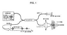
図1は、従来の時間ドメインOCTシステムの概略図を示す。参照アーム経路長を走査すると、干渉縞が、同じ体積で描かれた3つの構造体への距離に匹敵する位置に対応して形成される。単一の検出器を用いて、干渉縞を検出する。干渉縞パターンの包絡線検出によって、組織の反射率を所定の位置にマッピングする画像が構成される。 FIG. 1 shows a schematic diagram of a conventional time domain OCT system. When scanning the reference arm path length, interference fringes are formed corresponding to positions comparable to the distance to three structures drawn in the same volume. A single detector is used to detect interference fringes. By detecting the envelope of the interference fringe pattern, an image that maps the reflectance of the tissue to a predetermined position is formed.
本発明の或る例示の実施形態は、スペクトルレーダ概念(更に、スペクトルドメインOCTと称する)に基づく検出原理、又はスペクトルドメインと、現在の最先端技術による時間ドメインOCTより更に良い感度を持ち得る時間ドメインOCTとの間の複合の方法を提供して、取得速度対解像度比を実質的に大きくできる。 Certain exemplary embodiments of the present invention provide a detection principle based on a spectral radar concept (further referred to as spectral domain OCT), or spectral domain, and time that may have better sensitivity than current state-of-the-art time domain OCT. A composite method between domain OCT can be provided to substantially increase the acquisition speed to resolution ratio.
スペクトルドメインOCTにおけるショット雑音低減の原理
雑音がショット雑音限定である場合、時間ドメインOCTシステムの最大の信号対雑音性能が得られる。ショット雑音は、単一の要素検出器を多要素アレイ検出器で置き換えることによって大幅に低減し得る。検出アーム光がアレイ検出器上でスペクトル的に分散されると、アレイの各要素は、光源のスペクトル幅におけるわずかな波長の一部を検出する。ショット雑音は、好適には、アレイの要素数に等しい係数だけ低減される。信号対雑音改善の原理は、ショット雑音に固有なホワイト雑音と、同じ波長の電磁波だけが干渉縞を生成するという観察とに基づく。Principle of shot noise reduction in spectral domain OCT If the noise is shot noise limited, the maximum signal to noise performance of the time domain OCT system is obtained. Shot noise can be significantly reduced by replacing a single element detector with a multi-element array detector. When the detection arm light is spectrally dispersed on the array detector, each element of the array detects a fraction of the wavelength in the spectral width of the light source. Shot noise is preferably reduced by a factor equal to the number of elements in the array. The principle of signal-to-noise improvement is based on white noise inherent in shot noise and the observation that only electromagnetic waves of the same wavelength generate interference fringes.
ショット雑音パワー密度Nshot(f)([W/Hz]、[A2/Hz]又は[V2/Hz]単位による)は、検出器で生成される電流(又は、等価的に光学的パワー×量子効率)に比例する。干渉計に入射する波長λ1の単色ビームの場合、干渉縞周波数又は検出器における搬送波fは、ミラーの速度vによって求められ、f1=2v/λ1である。ショット雑音は、波長λ1でのパワー(又は、スペクトル密度S(ω))に比例する。第2波長λ2は、好適には、干渉計に結合される。周波数f2=2v/λ2での第2干渉縞周波数又は搬送波は、同時に存在する。この第2周波数におけるショット雑音は、好適には、波長λ1及びλ2における光学的パワーによって生成されるショット雑音の合計である。また、周波数f1において、ショット雑音は、波長λ1及びλ2における光学的パワーによって生成されるショット雑音の合計である。従って、両周波数において、相互ショット雑音項が、検出器における両波長が同時に存在することによって生成される。各波長を別々の検出器にスペクトル的に分散することによって、相互ショット雑音項は、消去し得る。このようにして、スペクトルドメインOCTは、時間ドメインOCTシステムと比較して、信号対雑音比の大幅な改善を提供する。The shot noise power density Nshot (f) (in [W / Hz], [A2 / Hz] or [V2 / Hz] units) is the current generated by the detector (or equivalently optical power). X Quantum efficiency). For a monochromatic beam of wavelength λ1 incident on the interferometer, the fringe frequency or the carrier f at the detector is determined by the mirror velocity v, f1 = 2v / λ1 . Shot noise is proportional to the power (or spectral density S (ω)) at wavelength λ1. The second wavelength λ2 is preferably coupled to the interferometer. The second fringe frequency or carrier at frequency f2 = 2v / λ2 exists simultaneously. This shot noise at the second frequency is preferably the sum of shot noise generated by optical power at wavelengths λ1 and λ2 . In addition, at the frequency f1 , shot noise is the sum of shot noise generated by optical power at wavelengths λ1 and λ2 . Thus, at both frequencies, a mutual shot noise term is generated by the simultaneous presence of both wavelengths at the detector. By spectrally distributing each wavelength to a separate detector, the mutual shot noise term can be canceled. In this way, spectral domain OCT provides a significant improvement in signal to noise ratio compared to time domain OCT systems.
時間ドメイン対スペクトルドメインOCTの信号対雑音解析
信号
時間ドメインOCTにおける信号対雑音比(SNR)の解析は、関連の発行物に記述されている。時間ドメインOCTにおける干渉縞ピーク振幅は、下式によって与えられる。
熱、ショット雑音及び相対強度雑音の影響
OCT信号の全雑音に対する3の影響は、熱雑音、ショット雑音及び相対強度雑音である。熱雑音は、フィードバック抵抗器によって生成され、ショット雑音は、電荷量が有限である性質に関連して、電流に統計的な変動を生じさせ、相対強度雑音は、古典的な光源の無秩序な性質による時間的な変動に関連する。雑音密度に対するこれら3つの影響は、単位[A2/Hz]で下式によって与えられる。
信号対雑音比(SNR)
信号対雑音比(SNR)は、下式で与えられる。
The signal to noise ratio (SNR) is given by:
OCT信号の空間及び周波数ドメイン記述
OCT信号は、空間ドメインで最も簡単に記述される。サンプルアーム中の単一の物体の場合、OCT信号の干渉項は、光源スペクトラムS(ω)のフーリエ変換の実数部に比例する。
また、式(9)は、光源の各角周波数又は等価的に光源の各波長は、測定された干渉計信号におけるそれ自体の周波数で表されることを実証する。深度プロファイル情報I(t)は、フーリエ変換によって、複素相互スペクトル密度I(f)から得ることができる。 Equation (9) also demonstrates that each angular frequency of the light source, or equivalently, each wavelength of the light source, is represented by its own frequency in the measured interferometer signal. The depth profile information I (t) can be obtained from the complex cross spectral density I (f) by Fourier transform.
また、複素相互スペクトル密度は、分散性の又は干渉計の要素を用いて、信号I(t)を幾つかのスペクトル帯域に分割することによって得ることができる。各検出器では、複素相互スペクトル密度の一部だけが求められる。各検出器の相互スペクトル密度を組み合わせて、信号の全スペクトル密度が回復される。 The complex cross spectral density can also be obtained by dividing the signal I (t) into several spectral bands using dispersive or interferometric elements. For each detector, only a portion of the complex cross spectral density is determined. The cross spectral density of each detector is combined to restore the full spectral density of the signal.
従って、スペクトル成分を個々の検出器に分離することによって、同じ情報を得ることができる。ソフトウェア又はハードウェアにおいて、全ての検出器の信号を組み合わせると、単一の検出器で得られたものと同じ信号になる。 Thus, the same information can be obtained by separating the spectral components into individual detectors. In software or hardware, combining the signals of all detectors results in the same signal as that obtained with a single detector.
スペクトルドメインOCTでの信号対雑音利得
検出アームにおいて、スペクトラムは、2等分できるが、この場合、2つの検出器は、各々、スペクトラムの半分を検出する。式(9)によれば、検出器1及び2における周波数スペクトルは、それぞれf<f0で|I1(f)|=S(πfc/v)、f>f0でI1(f)=0、f<f0でI2(f)=0、f>f0で|I2(f)|=S(πfc/v)である。時間ドメインOCTにおいて単一の検出器によって取得される周波数スペクトラムは、I1(f)とI2(f)の合計によって与えられ、I(f)=I1(f)+I2(f)となる。従って、スペクトル合成後、信号Sは、等しいが、f>f0でI1(f)=0、f<f0でI2(f)=0であり、検出器当たりの帯域幅BWは、2分の1に低減し得る。In the signal to noise gain detection arm in thespectral domain OCT, the spectrum can be divided into two equal parts, but in this case, the two detectors each detect half of the spectrum. According to equation (9), the frequency spectrum in the
雑音は、検出器1及び2におけるショット雑音の影響の合計により求められる。式(5)及び(6)から、検出器当たりのショット雑音は、検出器における参照アームパワー×検出器の帯域幅に比例する。スペクトラムが2等分されたため、検出器1及び2における参照パワーは、それぞれ下式で与えられる。
上記の解析を拡張すると、ショット雑音の影響は、検出器数に等しい係数だけ低減されることを実証し得る。各検出器要素が総参照パワーのN分の1を受光するN検出器要素のショット雑音の合計は、下式で与えられる。
利点
本発明の例示の実施形態は、ショット雑音及び他の形態の雑音を低減し、これによって、現行のシステムより大幅に小さい光源パワー又は大幅に大きい取得レートを可能にする。検出感度が大きくなると、リアルタイムの画像形成が可能になる。このような画像形成速度は、胃腸、眼科及び動脈の画像形成環境等において、体動が継続的な問題である場合、開業医を支援し得る。信号対雑音比を維持又は改善しつつフレームレートを大きくすることによって、このような体動は、解消し得る。また、本発明によって、OCTで広い領域の組織を検診することが可能になり、また、この方法を用いて、臨床的に実行可能な検診手順が可能になる。Advantages Exemplary embodiments of the present invention reduce shot noise and other forms of noise, thereby allowing significantly lower light source power or significantly higher acquisition rates than current systems. When the detection sensitivity increases, real-time image formation becomes possible. Such imaging speeds can assist practitioners when body movement is a continuous problem in gastrointestinal, ophthalmic and arterial imaging environments. By increasing the frame rate while maintaining or improving the signal-to-noise ratio, such body movement can be eliminated. In addition, the present invention makes it possible to examine a wide area of tissue by OCT, and a clinically feasible examination procedure using this method.
図2は、本発明の例示の実施形態による上位レベルシステム100の構成を示し、光源アーム104、サンプルアーム106、参照アーム108、及び検出アーム110を有する干渉計102を含み、検出アーム110は、スペクトル分離ユニット112、多数の検出器114、増幅器116、(図示しないが当業者には公知である)オプションのアナログ処理電子回路118、及び(図示しないが当業者には公知である)信号変換用のA/D変換器120を有する。処理・表示ユニット122は、オプションとして、デジタル帯域通過フィルタ処理(BPF)ユニット124、デジタル高速フーリエ変換(FFT)126(図示せず)、信号のコヒーレント合成、及びデータ処理・表示アルゴリズムを有する。検出器アレイ114は、単純な強度測距及び画像形成及び/又はドップラ感受性の検出では1xN、二重平衡検出では2xN、単純な強度測距及び/又は偏光及び/又はドップラ感受性の検出では2xN、又は合成二重平衡及び偏光及び/又はドップラ感受性の検出では4xNであってよい。他の選択肢として、サンプル130に関する横断的な空間情報の検出が可能なように、MxNアレイは、任意の数“M”の検出器114に用い得る。 FIG. 2 illustrates the configuration of the
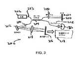
図3は、スペクトルドメインOCTシステム200の一例示実施形態の概略図を示し、システム200には、光源202、スプリッタ204、参照アーム206、サンプルアーム208、組織サンプル130、光学要素210、回折格子212、レンズ214、検出器216アレイ、及びプロセッサ218が含まれる。検出アーム光は、回折格子212によって分散され、スペクトラムは、検出器アレイ216に画像形成される。参照アーム206長を距離λ/8に渡り段階的に送ることによって、参照アーム206とサンプルアーム208光との相互スペクトル密度を求め得る。相互スペクトル密度のフーリエ変換は、深度プロファイル情報を生成する。 FIG. 3 shows a schematic diagram of an exemplary embodiment of a spectral domain OCT system 200 that includes a light source 202, a splitter 204, a
光源
光源アーム203は、低コヒーレンス光で干渉計を照射するために用いられる光源202を少なくとも含む。光源の時間的なコヒーレンス長は、好適には、数ミクロンより短い(好適な範囲は、約0.5μm乃至30μm)。光源の例には、これらに限定しないが、半導体光増幅器、超発光性ダイオード、発光ダイオード、固体フェムト秒光源、増幅式自然発光連続光源、熱光源、及びそれらの組み合わせ等が含まれる。当業者に知られている他の適切な光源を用いてもよい。本明細書では、光は光源と呼ぶが、このことは、状況に依存して、他の電磁放射の範囲も適切に用い得ることを意図している。The
干渉計
サンプルアーム208は、組織サンプル130から反射した光を集光し、参照アーム206からの光と合成して干渉縞を形成する。参照アーム206は、光源アーム203と合成するために光を戻す。また、参照アームは、反射の無い透過性であってもよい。このビーム分割/再合成の実行は、ビームスプリッタ204(マイケルソン)又はサーキュレータ(1つ又は複数)(マッハ‐ツェンダ)、又はビーム間の干渉を検出し得るように、ビームを複数の経路に分離し、これら複数のビームを再合成するための当業者に知られている他の手段を用いて行ない得る。この分割は、自由空間において、又は受動的な光ファイバ構成要素を有するスプリッタ204を用いることによって実現し得る。Interferometer sample arm 208 collects the light reflected from
サンプルアーム
LCI用途の場合、サンプルアームは、劈開された(傾斜した、平坦な、又は研磨した)光ファイバを含む光学プローブ又は自由空間ビームによって終端し得る。(これらに限定しないが、非球面型、屈折率分布型、屈折性、ボール型、ドラム型等の)レンズを用いて、サンプル上又はサンプル内にビームを集光し得る。また、ビーム誘導要素(これらに限定しないが、プリズム、又は屈折性光学要素等)をプローブ内に含み、集光されたビームをサンプル上の所望の位置に誘導し得る。OCT用途の場合、ビーム位置は、時間の関数としてサンプル上で変更して、二次元画像を再構築し得る。サンプル上での集光ビームの位置変更は、(これらに限定しないが、検流計、圧電アクチュエータ等の)走査ミラー、光電アクチュエータ、又は光ファイバを動かす(例えば、光ファイバを回転又は光ファイバを直線的に並進させる)ことによって実現し得る。サンプルアームプローブは、内部で動く要素を有する光ファイバプローブであってよく、この場合、その運動がプローブの基端部で起動され、また、その運動は、(これらに限定しないが、ワイヤ、ガイドワイヤ、速度計ケーブル、ばね、及び光ファイバ等の)運動変換装置によって遠端部に伝達し得る。光ファイバプローブは、光学的に透明な静止外装中に密閉し得るが、この場合、光は、遠端部でプローブから出射する。図4は、(プローブの軸に沿って回転又は直線的に並進し得る)内部ケーブル260、外部透明又は半透明外装262、遠端光学部品264、及び(カテーテルの軸に対して任意の角度での)出射光266を有する詳細図を示す。For sample arm LCI applications, the sample arm may be terminated by an optical probe or free space beam that includes a cleaved (tilted, flat, or polished) optical fiber. A beam (such as, but not limited to, aspherical, gradient index, refractive, ball, drum, etc.) may be used to focus the beam on or within the sample. A beam directing element (such as but not limited to a prism or refractive optical element) may also be included in the probe to direct the focused beam to a desired location on the sample. For OCT applications, the beam position can be changed on the sample as a function of time to reconstruct a two-dimensional image. Changing the position of the focused beam on the sample can move a scanning mirror (such as, but not limited to, a galvanometer, a piezoelectric actuator, etc.), a photoelectric actuator, or an optical fiber (eg, rotating an optical fiber or moving an optical fiber) Can be realized by linear translation). The sample arm probe may be a fiber optic probe having an internally moving element, in which case the movement is activated at the proximal end of the probe, and the movement may include (but is not limited to, wire, guide It can be transmitted to the far end by motion transducers (such as wires, speedometer cables, springs, and optical fibers). The fiber optic probe can be sealed in an optically transparent stationary sheath, in which case light exits the probe at the far end. FIG. 4 shows an inner cable 260 (which can be rotated or translated linearly along the probe axis), an outer transparent or translucent sheath 262, a far end optic 264, and (at any angle relative to the catheter axis). FIG. 2 shows a detailed view with
参照アーム遅延
参照アーム206の機構270により、参照アーム206のグループ遅延を走査し得る。このグループ遅延は、これらに限定しないが、光ファイバを延長することによって、圧電トランスデューサを用いる自由空間並進走査によって、又は、回折格子ベースのパルス整形光学遅延ラインを介して等、当業者に知られている多数の手法の何れかによって生成し得る。好適には、この遅延は、非機械的な又は不動の構成によって導入される。“非機械的”によって、機械的に動く部品が一切利用されないことを意味する。機械的に動く部品が存在しないと、機械的な装置を用いて遅延を導入するという既知の欠陥が減少すると考えられている。文献に記載されている従来のLCI又はOCTシステムとは反対に、本発明における参照アーム206は、必ずしもサンプルの全測距深度に渡って走査する必要はなく、好適には、少なくとも検出器数分の1(1/N)に等しい一部の測距深度に渡って走査する。この走査の特徴は、基本的に、従来知られているLCI及びOCTシステムに用いられる既知の遅延走査方式とは異なる。参照アーム206は、オプションとして、これらに限定しないが、音響光学変調器、電気光学位相変調器等、搬送波周波数を生成するための(本明細書において、より詳細に記述する)位相変調器機構を有する。参照アーム206の走査範囲を低減するために、スペクトラムは、好適には、以下に説明する方法に基づき、複数のスペクトル帯域に分割する。Reference arm delay The
検出
図2を参照すると、検出アーム110において、スペクトル分離ユニットは、スペクトル成分を分離し、信号は、別々の検出器114に転送される。検出器114は、好適には、(これらに限定しないが、シリコン、InGaAs、拡張InGaAs等の)受光ダイオードで構成し得る。他の選択肢として、(これらに限定しないが、受光ダイオードアレイ、CCD、CMOSアレイ、能動CMOSアレイ、CMOS“スマート画素”アレイ、及びそれらの組み合わせ等の)一次元又は二次元アレイ検出器114を検出に用い得る。各スペクトル帯域用の2つの検出器114は、再合成光を直交偏光固有状態に分離した後、偏光感受性検出に用い得る。検出器114アレイは、単純な強度測距及び画像形成及び/又はドップラ感受性検出の場合1xN、二重平衡検出の場合2xN、強度測距及び画像形成及び/又は偏光感受性及び/又はドップラ感受性検出の場合2xN、又は合成二重平衡及び強度測距及び/又はドップラ感受性及び/又は偏光感受性検出の場合4xNであってよい。他の選択肢として、MxNアレイを任意のMに対して用いて、サンプル40に関する横断的な空間情報を検出し得る。Detection Referring to FIG. 2, in the
検出器信号は、トランスインピーダンス増幅器(TIA)116、帯域通過フィルタ124によって(デジタル的に又はアナログ回路を用いて)増幅され、A/D変換器によってデジタル化され、コンピュータ122に記憶されて、更に処理し得る。各検出器114は、好適には、ショット雑音限定に構成し得る。ショット雑音限定の検出は、好適には、ショット雑音がTIA116の抵抗器の熱雑音を支配し、また、相対強度雑音(RIN)より大きくなるように、参照アーム108からの戻り光の強度を調整することによって実現される。各検出器114は、このような二重雑音低減の場合、平衡状態である。 The detector signal is amplified (digitally or using analog circuitry) by a transimpedance amplifier (TIA) 116,
本発明の一実施形態において、検出器114の数Nは、2乃至10、000以上の範囲であってよい。Nの好適な範囲は、約8乃至10、000検出器である。好適な一実施形態において、8つの検出器114(又は、その領域の或る数)が、リアルタイムの又はリアルタイムに近い画像形成を提供し得る。 In one embodiment of the invention, the number N of
他の選択肢として、他の検出方法には、好適には、1/f雑音(f=周波数)(図5参照)より大きいレートで画像を得ることができる積分式一次元又は二次元検出器114アレイが含まれる。オプションとして、BPFは、デジタル化に続いて個別に実現し得る。付加的な修正には、平衡検出のためにオプションの第2検出器115アレイを用いることが含まれ、このことで、RIN及び1/f雑音の低減により、参照アームパワーが大きくなり、また、取得速度が速くなる。好適な実施形態において、位相追跡装置及び/又はアルゴリズムは、干渉縞の不安定性による信号減衰を低減するために参照アーム108に用いられる。 As another option, other detection methods are preferably integrated one-dimensional or two-
このシステムは、単一の検出器114を用いて、二重平衡行のアレイ検出器をインターリーブ処理することによって又は互いに隣接して2つの同じアレイ検出器を配置することによって二重平衡検出を使用可能状態にして実現し得る。2つのアレイ検出器114及び115が用いられる場合、それらの値は、互いに減算して二重平衡検出を実現する。2つを超えるアレイ検出器が用いられる場合、それらの信号は選択的に減算でき、また、複素スペクトル密度を得ることができる。 This system uses double balanced detection using a
波長の関数としてのスペクトル強度は、好適には、一定である。しかしながら、そうでない場合、スペクトラムは、参照、サンプル及び/又は光源アームにおいて整形され、それを一定にできる。スペクトル整形器は、当分野では公知である。 The spectral intensity as a function of wavelength is preferably constant. However, if not, the spectrum can be shaped at the reference, sample and / or light source arm and made constant. Spectral shapers are known in the art.
処理
各検出器114の信号は、FFT等によって、信号周波数を中心にして帯域通過フィルタ処理される。全ての検出器114の信号は、上述したように合成して、周波数ドメインにおける複素相互スペクトル密度を得ることができる。フーリエ変換によって、複素相互スペクトル密度は、組織中の深度プロファイルに変換し得る。参照アームにおいてπ/2の位相シフトの少なくとも2つの信号を得た後、これら2信号の何らかの線形合成により複素スペクトル密度を再構築することによって等、これらに限定しないが、複素スペクトル密度を処理して深度プロファイル情報を得るための幾つかの方法が、当業者に知られている。Processing The signal of each
検出に続いて、アナログ処理には、トランスインピーダンス増幅器、帯域通過フィルタ、及び信号のデジタル化が含まれる。そして、この信号は、フーリエ変換演算によって深度の関数として反射率に変換し得る。デジタル処理には、デジタル化、周波数ドメイン又は時間ドメイン(FIR又はIIRフィルタ)におけるデジタル帯域通過フィルタ処理、及び深度の関数として組織反射率を回復するための逆フーリエ変換が含まれる。 Following detection, analog processing includes transimpedance amplifiers, bandpass filters, and signal digitization. This signal can then be converted to reflectivity as a function of depth by a Fourier transform operation. Digital processing includes digitization, digital bandpass filtering in the frequency or time domain (FIR or IIR filter), and an inverse Fourier transform to recover tissue reflectance as a function of depth.
システム統合
多数の信号の処理は、数学的な画像再構築、表示、データ記憶を含む基本的な処理を行なう画像形成又は診断用のコンソールを用いて行ない得る。他の選択肢として、図6に示す他の実施形態は、既設のOCT及び/又はLCIシステムに接続し得るスタンドアロンの検出・処理システム300を示す。この場合、検出器302及びデジタル化は、スタンドアロンユニット中で実施し得る。スタンドアロンユニットへの入力は、上述したように、参照及びサンプルアーム双方からの合成光である。システムの出力は、先のOCT又はLCIコンソール入力と同様であるがSNRが大きくなった干渉計の信号である。スタンドアロンユニットには、波長をスペクトル帯域に分割するためのスプリッタ304、多数の検出器302、TIA306を含むアナログ回路、及び上述したように、干渉計の信号を再構築するための装置が含まれる。干渉計の信号を再構築するための装置には、アナログ又はデジタル装置が含まれ、この場合、アナログ装置には、帯域通過フィルタ(BPF)308と、各波長帯域からの個々の干渉図形を加算するためのアナログ構成とが含まれる。デジタル装置には、アナログーデジタル変換器と、各スペクトル帯域からの干渉図形を単一の全帯域幅干渉計信号に再合成し得るCPU310とが含まれる。そして、再構築された干渉図形は、スタンドアロンシステムの出力になり得る。あるいは、他の選択肢として、再構築された干渉図形復調信号を既設のシステムコンソールへの入力として用い得る。System Integration Multiple signal processing can be performed using an imaging or diagnostic console that performs basic processing including mathematical image reconstruction, display, and data storage. As another option, another embodiment shown in FIG. 6 shows a stand-alone detection and processing system 300 that may be connected to an existing OCT and / or LCI system. In this case,
参照アームの走査範囲
サンプル130の測距深度は、それによって相互スペクトル密度を求め得る解像度によって求められる。単一の検出器を用いる方法では、複素スペクトル密度のスペクトル解像度は、参照アームの走査範囲によって求められる。走査範囲が広ければ広いほど、スペクトル解像度は大きくなり、また、サンプル中の測距深度が大きくなる。スペクトル分離ユニット及び多数の検出器を有するシステムでは、相互スペクトル密度の解像度は、参照アーム走査範囲とスペクトル分離特性の組み合わせである。The ranging depth of thereference arm
任意の適切な波長帯域形状は、分離に用い得る。任意のスペクトル帯域形状の場合、参照アーム18の走査範囲は、各帯域において完全にスペクトル成分を分解するのに必要な遅延によって求められる。 Any suitable wavelength band shape can be used for separation. For any spectral band shape, the scan range of the reference arm 18 is determined by the delay necessary to completely resolve the spectral components in each band.
例えば、好適な一実施形態において、図7に示すように、スペクトル分離ユニットは、スペクトラムを2つの帯域に分割し得るが、この場合、各帯域は、櫛状構造の一組の狭いスペクトルから構成される。図7Aは、検出器#1でのスペクトル帯域を示す。図7Bは、検出器#2でのスペクトル帯域を示す。図7Cは、両検出器の合成スペクトル帯域を示す。各検出器24の櫛状スペクトル帯域をインターリーブ処理すると、連続スペクトラムが再現される。個々の検出器においてスペクトラムを分解するのに必要な解像度は、単一の検出器システムにおいて必要とされるものの半分であり、従って、サンプル130中で同じ測距深度を維持しつつ、参照アームの走査範囲は、2分の1だけ低減できる。他の実施形態において、スペクトル分離ユニットは、参照アーム中にあってよい。図8において、スペクトラムを幾つかのスペクトル帯域に分割するための例を示す。この例では、参照アームの走査範囲は、サンプル中の測距深度を同じに維持しつつ、スペクトル帯域数に関連する係数だけ低減し得る。 For example, in one preferred embodiment, as shown in FIG. 7, the spectral separation unit may divide the spectrum into two bands, where each band is composed of a set of narrow spectra of a comb structure. Is done. FIG. 7A shows the spectral band at
波長分離フィルタの実施形態
スペクトラムを分離又は分散するための幾つかの手法が知られている。1つの方法は、回折格子及びマイクロレンズアレイを用いて、スペクトル成分を個々の検出器に集光する。第2の方法は、回折格子の代わりにプリズムを用いる。第3の方法は、回折格子及びアドレス指定可能なミラーアレイ(これらに限定しないが、“MEMS”ミラー又はデジタル光処理(DLP)装置等)を用いて、スペクトル成分を個々の検出器に導く。第4の方法は、アレイ状の個別検出器の前に線形アレイの光学フィルタを用いる。第5の方法は、所望のフィルタ作用を有するパターンを生成するために、ある材料にエッチングされた又は光ファイバ成分から製造された導波路を用いる。一例として、図8において、スペクトラムを帯域に分割する導波路フィルタの例示の実施形態を示す。第6の方法は、インターリーブ処理された又は任意のスペクトル帯域を生成するためにアレイ状の導波路回折格子(AWG)を用いる。Embodiments of Wavelength Separation Filters Several techniques are known for separating or dispersing the spectrum. One method uses a diffraction grating and a microlens array to focus spectral components onto individual detectors. The second method uses a prism instead of the diffraction grating. A third method uses a diffraction grating and an addressable mirror array (such as, but not limited to, a “MEMS” mirror or a digital light processing (DLP) device) to direct spectral components to individual detectors. The fourth method uses a linear array of optical filters in front of the array of individual detectors. The fifth method uses a waveguide etched into a material or manufactured from an optical fiber component to produce a pattern with the desired filter action. As an example, FIG. 8 shows an exemplary embodiment of a waveguide filter that divides the spectrum into bands. The sixth method uses an arrayed waveguide grating (AWG) to generate an interleaved or arbitrary spectral band.
相対強度雑音
検出器に存在する雑音項の1つは、相対強度雑音(RIN)又はボーズ・アインシュタイン雑音である。RIN雑音は、数ナノメータ未満のスペクトル幅の場合、ショット雑音に対して支配的になる可能性がある。数多くの検出器構成の場合、各検出器におけるスペクトル幅は、数ナノメータより小さい可能性があり、相対強度雑音は、全体的なシステム雑音を支配し得る。従って、好適には、平衡検出を実現して、RINを排除し得る。当分野において知られている幾つかの方法が、平衡検出を実現するために存在している。1つのこのような方法について、更に詳細に以下論ずる。例えば、限定はしないが、図9に示すように、参照アーム400及びサンプルアーム402からの光は、若干異なる角度で回折格子404に入射して反射され、線形NxM光検出器アレイ406に集光される。アレイのN方向(列)に沿って、波長が符号化される。アレイのM方向(行)に沿って、特定の波長におけるサンプル及び参照アームの干渉パターンが記録される。サンプル及び参照アーム光は、若干異なる角度で入射したため、干渉の極大及び極小のパターンが、列方向に存在する。平衡検出は、極大及び極小パターンに対して厳密に位相がずれているダイオード信号を減算することによって実現し得る。他の選択肢として、平衡検出は、列方向の干渉パターンの振幅を測定することによって実現し得るが、このことは、極大又は干渉パターンを列に沿う干渉パターンの極小から減算することによって実現し得る。平衡検出のための他の実施形態は、参照及びサンプルアーム光400、402を合成して、双方の間の位相シフトがπである干渉信号を有する2つの出力を生成することである。このことは、ビームスプリッタ又は他のビーム再合成要素の両出力ポートを利用することによって実現し得る。そして、2つの信号は、別々に検出され減算し得る。干渉項を含む信号は、位相がπだけシフトしているため、これらの項は、減算の演算時強め合うように加算される。RINを含む信号部分は、しかしながら、減算時相殺される。減算の演算は、全てのM要素に対して行なうことができ、また、アナログ又はデジタルドメインで行なうことができる。減算がアナログドメインで行なわれる場合、信号の帯域幅は、2分の1に低減され、好適には、指定されたデジタル化のパラメータやコンピュータバス上でのデータ転送が
減少する。One of the noise terms present in therelative intensity noise detector is relative intensity noise (RIN) or Bose-Einstein noise. RIN noise can be dominant over shot noise for spectral widths less than a few nanometers. For many detector configurations, the spectral width at each detector can be less than a few nanometers and the relative intensity noise can dominate the overall system noise. Thus, preferably, equilibrium detection can be implemented to eliminate RIN. Several methods known in the art exist to achieve equilibrium detection. One such method is discussed in further detail below. For example, without limitation, as shown in FIG. 9, light from the reference arm 400 and the
このような平衡検出の例を図10に示すが、これについては、本明細書において、以下に更に詳述する。平衡検出出力は、RINを相殺する平衡が取れた信号を生成するために減算される。 An example of such equilibrium detection is shown in FIG. 10, which will be described in further detail herein below. The balanced detection output is subtracted to produce a balanced signal that cancels RIN.
スペクトル分離及び検出後の信号を再構築するための信号処理
本発明の例示の実施形態の非限定的例示として、2つの事例、最初に、連続スペクトル帯域(ブロック)の事例、2番目に、図7に示す櫛状スペクトル帯域の事例について以下に議論する。Signal Processing for Reconstructing Signals After Spectral Separation and Detection As a non-limiting illustration of an exemplary embodiment of the present invention, two cases, first, a continuous spectral band (block) case, second, a diagram An example of the comb spectrum band shown in FIG. 7 will be discussed below.
事例A:連続スペクトル帯域
検出アーム光は、Nスペクトルブロックに分割され、この場合、各スペクトルブロックは、2つの光周波数間の強度を含む。
事例B1:櫛状スペクトル帯域及び低減された参照アーム走査からのサンプルアームにおける全深度範囲の再構築 Example B1: Reconstruction of the full depth range in the sample arm from a comb-like spectral band and reduced reference arm scan
以下に述べる次の説明は、本発明による低減された参照アーム走査からサンプルアームにおける全深度範囲の再構築の原理について記述するものである。その手順については、スペクトラムを2つのスペクトル帯域に分離する事例について述べるものとする。例示の方法は、数多くのスペクトル帯域への分離に対して拡張し得る。 The following description which follows will describe the principle of reconstruction of the full depth range in the sample arm from the reduced reference arm scan according to the present invention. As for the procedure, an example of separating a spectrum into two spectrum bands will be described. The example method may be extended for separation into a number of spectral bands.
単一の検出器システムの検出器における信号は、R(t)によって定義される。サンプルの深度範囲は、単一のAライン(深度プロファイル)の測定時間T×参照アーム遅延ラインにより生成された群速度、Zrange=vgTによって与えられる。The signal at the detector of a single detector system is defined by R (t). The depth range of the sample is given by a single A-line (depth profile) measurement time T × group velocity generated by the reference arm delay line, Zrange = vg T.
FFT後における最小の分解可能な周波数は、1/Tによって与えられ、これは、最小分解可能角周波数Δω=2π/Tを与える。図8に示すフィルタは、信号を2つの帯域に分割するが、ピークは、それぞれ、ω=ω0、ω0+2Δω、ω0+4Δω等、また、ω=ω0+Δω、ω0+3Δω等である。The minimum resolvable frequency after FFT is given by 1 / T, which gives the minimum resolvable angular frequency Δω = 2π / T. The filter shown in FIG. 8 divides the signal into two bands, but the peaks are ω = ω0 , ω0 + 2Δω, ω0 + 4Δω, etc., and ω = ω0 + Δω, ω0 + 3Δω, etc. .
Bl(t)及びB2(t)は、それぞれ帯域1及び2の信号である。フーリエ変換後のスペクトル帯域1及び2の信号は、Bl(ω)=R(ω)cos2(ωT/4)及びB2(ω)=R(ω)sin2(ωT/4)によって与えられる。Bl (t) and B2 (t) are signals in
また、フーリエドメインにおけるこの積は、時間ドメインにおける畳み込みとして表し得る。信号が時間Tに対して周期的であると仮定すると、信号B1(t)及びB2(t)は、B1(t)=R(t)+R(t+T/2)及びB2(t)=R(t)−R(t+T/2)によって与えられる。This product in the Fourier domain can also be expressed as a convolution in the time domain. Assuming that the signal is periodic with respect to time T, the signals B1 (t) and B2 (t) are B1 (t) = R (t) + R (t + T / 2) and B2 (t ) = R (t) -R (t + T / 2).
上式を用いて、t=0からt=Tまでの信号R(t)は、t=0からt=Tまで記録された信号B1(t)及びB2(t)から、0<t<T/2の場合、R(t)=B1(t)+B2(t)及びR(t+T12)=Bl(t)−B2(t)のように表すことによって再構築し得る。大きなN>2の場合、R(t)がB1からBNまで再構築されるように、同一の手順が実施される。Using the above equation, the signal R (t) from t = 0 to t = T can be expressed as 0 <t from the signals B1 (t) and B2 (t) recorded from t = 0 to t = T. In the case of <T / 2, it can be reconstructed by expressing R (t) = B1 (t) + B2 (t) and R (t + T12) = B1 (t) −B2 (t). For large N> 2, the same procedure is performed so that R (t) is reconstructed from B1 to BN.
このことは、信号B1(t)及びB2(t)は、深度範囲zrangeの半分だけ記録すればよいことを実証する。従って、参照アームにおける深度測距は、サンプルの測距深度が同じままで、2分の1だけ低減し得る。図7に示すように、信号が更に多くのスペクトル帯域に分割される場合、上述したものと同じ手順によって、サンプルの測距深度が同じままで、N分の1だけ(Nはスペクトル帯域数)参照アームの深度走査を低減し得る。This demonstrates that signals B1 (t) and B2 (t) need only be recorded for half of the depth range zrange . Thus, depth ranging in the reference arm can be reduced by a factor of two while the sample ranging depth remains the same. As shown in FIG. 7, if the signal is divided into more spectral bands, the same procedure as described above keeps the sample ranging depth the same, only 1 / N (N is the number of spectral bands) Reference arm depth scanning may be reduced.
上述した手順の例示のフロー図は、図11に示す。 An exemplary flow diagram of the procedure described above is shown in FIG.
事例B2:多数のスペクトル帯域の限界
多数のスペクトル帯域N>=L/λの限界において、参照アームの光学的経路長変化は、波長λのそれに近づく。この限界において、1つの波長全体の位相変化のみが、長さL上での全軸方向の走査を再構築するために必要である。この場合、参照アーム経路遅延は、参照アーム遅延を走査するための上記方法のいずれかを用いることによって実現し得る。本発明による他の好適な方法は、電気光学変調器、音響光学変調器、又は位相制御の挿入を含み、参照アーム経路における光学遅延ライン(RSOD)を迅速に走査して1つの波長の経路長遅延を与える。また、この場合、波長分離ユニットは、波長を櫛パターンに分離しないが、スペクトラムを固有の光周波数に分離し、各周波数が単一の検出器で検出される。Case B2: Limit of multiple spectral bands In the limit of multiple spectral bands N> = L / λ, the optical path length change of the reference arm approaches that of wavelength λ. At this limit, only a phase change across one wavelength is necessary to reconstruct an omnidirectional scan over length L. In this case, the reference arm path delay may be achieved by using any of the above methods for scanning the reference arm delay. Other preferred methods according to the present invention include the insertion of electro-optic modulators, acousto-optic modulators, or phase control, and quickly scan the optical delay line (RSOD) in the reference arm path to one wavelength path length. Give a delay. In this case, the wavelength separation unit does not separate the wavelengths into comb patterns, but separates the spectrum into unique optical frequencies, and each frequency is detected by a single detector.
事例C:任意の波長パターンのフーリエドメイン再構築
時間又は空間ドメインにおけるLCI又はOCT信号の再構築と対照的に、信号は、各波長帯域の複素スペクトル成分を加算することによって、フーリエドメインにおいて再構築してLCI又はOCT信号のフーリエ変換を構成し得る。各フーリエ成分の位相変更は、参照アーム遅延長を補正するために、或る選択された状況では好まれることがある。Case C: Fourier domain reconstruction of arbitrary wavelength pattern In contrast to LCI or OCT signal reconstruction in time or space domain, the signal is reconstructed in Fourier domain by adding the complex spectral components of each wavelength band Thus, a Fourier transform of the LCI or OCT signal can be constructed. A phase change of each Fourier component may be preferred in certain selected situations to correct the reference arm delay length.
画像又は一次元の軸方向走査の再構築
実数ドメインにおけるLCI又はOCT信号の再構築に続き、軸方向の反射率は、再構築されたLCI又はOCT信号を復調することによって求め得る。復調の構成には、正弦波・低域通過フィルタ処理、包絡線検出を用いる包絡線復調、2乗復調・低域通過フィルタ処理、FIRに続く直角復調、IIRフィルタ処理、又は低域通過フィルタ処理による乗算を含み得る。更に、ストークスベクトル(偏光)及びこれらのLCI又はOCT信号からのフローの再構築は、当業者に公知である。再構築及び復調に続き、データは、一次元又は二次元フォーマット(画像)で表示され解釈されて最終的に組織の状態や媒体中の欠陥の診断を行ない得る。フーリエドメインにおいてLCI又はOCT信号が再構築される場合、フーリエドメインにおけるこのような再構築された信号は、フーリエスペクトラムをシフトし、また、逆フーリエ変換を行なうことによってフーリエドメインで復調し得る。その結果、実数ドメイン(直角信号)における複素信号は、次に、直角信号の実数部の振幅を算出することによって、軸方向の反射率情報に再構築される。複素成分は、偏光又はフロー情報を算出するために用いられる。他の選択肢として、信号がフーリエドメインで再構築される場合、これは、実数ドメインに直接逆フーリエ変換して、再構築された実数ドメイン信号に対して述べた上記処理を受けることができる。Reconstruction of the LCI or OCT signal in the real domain of theimage or one-dimensional axial scan reconstruction . The axial reflectance can be determined by demodulating the reconstructed LCI or OCT signal. The demodulation configuration includes sine wave / low-pass filter processing, envelope demodulation using envelope detection, square demodulation / low-pass filter processing, quadrature demodulation following FIR, IIR filter processing, or low-pass filter processing May include multiplication by. Furthermore, the reconstruction of the Stokes vector (polarization) and the flow from these LCI or OCT signals is known to those skilled in the art. Following reconstruction and demodulation, the data can be displayed and interpreted in one-dimensional or two-dimensional format (images) to ultimately diagnose tissue conditions and defects in the media. When an LCI or OCT signal is reconstructed in the Fourier domain, such reconstructed signal in the Fourier domain can be demodulated in the Fourier domain by shifting the Fourier spectrum and performing an inverse Fourier transform. As a result, the complex signal in the real domain (quadrature signal) is then reconstructed into axial reflectance information by calculating the amplitude of the real part of the quadrature signal. The complex component is used to calculate polarization or flow information. As another option, if the signal is reconstructed in the Fourier domain, it can be directly inverse Fourier transformed to the real domain and subjected to the processing described above for the reconstructed real domain signal.
図12は、光源502、504、及び506のスペクトル合成及び参照アームにおける搬送波の音響光学的生成を示すスペクトルドメインOCT干渉計設計500の例示の実施形態を示す。AOMと表示したブロックは、音響光学変調器508、510である。2つの出力は、各々、別々の(図3及び13に示す)スペクトル検出ユニット114、115に入り平衡検出される。 FIG. 12 shows an exemplary embodiment of a spectral domain
第150/50スプリッタ及び80/20スプリッタにおける光源光のスペクトル合成後、光は、改良型マイケルソン干渉計に入射する。平衡検出を実現する構成を示す。サンプルアームは、プローブ(例えば、スリットランプ)に至る。参照アーム光は、差分周波数が10kHzである2つの音響光学変調器を介して送信され、波長とは独立な一定の搬送波周波数を生成する。平衡検出出力は、更に、別々のスペクトル検出ユニットに至る。 After spectral synthesis of the source light in the 150/50 splitter and 80/20 splitter, the light is incident on an improved Michelson interferometer. The structure which implement | achieves a balance detection is shown. The sample arm leads to a probe (eg, a slit lamp). The reference arm light is transmitted through two acousto-optic modulators having a differential frequency of 10 kHz, and generates a constant carrier frequency independent of the wavelength. The balanced detection output further leads to a separate spectral detection unit.
スペクトル検出ユニット
図13において、スペクトルドメインOCTの中心は、多要素アレイ114への検出アーム光のスペクトル分離である。検出アームビーム520は、回折格子520によってスペクトル的に分離され、レンズ522によって多要素アレイ114上に集光される。Spectral Detection Unit In FIG. 13, the center of the spectral domain OCT is the spectral separation of the detection arm light into the
N検出器要素を有する走査カメラが、スペクトル検出ユニット128として用いられる(図2参照)。好適には、平衡検出は、第2ライン走査カメラを加えることによって実現される。当業者に知られているように、深度範囲は、スペクトル解像度に逆比例する。複素スペクトル密度の実数部が求められる場合、測距深度zは、下式によって定義される。
二重平衡検出
二重平衡検出は、好適には、本発明によって用いられ、これは、好適には、以下の理由で利用される。第1に、ほとんどの光源が、相対的に低い周波数で1/f雑音(f=周波数)を生成する。平衡検出は、1/f光源雑音を解消する。第2に、サンプルアーム光のそれ自体との干渉項(自己相関項)が、実際の信号項上に存在するが、これは、サンプルと参照アームとの間の干渉である。この自己相関項は、差分法によって除去し得る。平衡検出は、この自己相関項を測定信号から除去し得る。第3に、RINは、低減し得る。Double balanced detection Double balanced detection is preferably used by the present invention, which is preferably utilized for the following reasons. First, most light sources generate 1 / f noise (f = frequency) at relatively low frequencies. Balance detection eliminates 1 / f light source noise. Secondly, an interference term (autocorrelation term) with the sample arm light itself exists on the actual signal term, which is interference between the sample and the reference arm. This autocorrelation term can be removed by the difference method. Balance detection may remove this autocorrelation term from the measurement signal. Third, RIN can be reduced.
データ取得・処理ユニット
2000検出器要素及び8乃至10ビット解像度(ほとんどのライン走査カメラのダイナミックレンジ)で、1秒間当たり20、000スペクトルプロファイルのデータレートは、40乃至80MB/秒である。PCIバス上で維持可能な最大データ転送速度は、100MB/秒である。コンピュータシステムメモリへの2つの独立PCIブリッジを有するコンピュータでは、同時に2つのライン走査カメラから約200MB/秒のデータを転送してデータのリアルタイム処理を行ない得る。デジタル化の前にライン走査カメラ信号を減算することによるアナログでの二重平衡検出の実現によって、データレートは2分の1だけ低減し得る。12乃至14ビットの解像度で、100Mサンプル/秒までの速度の高速データ取得ボードが入手可能である。2.5GHzペンティアム(登録商標)4プロセッサ上で単一の2048点高速フーリエ変換は、50μ秒要する。これらの数値は、20、000スペクトルプロファイル/秒でのスペクトルドメインOCTデータのリアルタイム処理が、デュアルプロセッサPCの現在のデータ取得・処理能力の到達範囲内であることを示す。分光計によって収集されたデータは、等しい波長増分でサンプリングし得る。しかしながら、フーリエ変換は、z及びk空間(又は、t及びw)をリンクする。kとλとの間の関係が非線形的であることから、分光計からのスペクトラムを補間して、kドメインにおいて均等に分散配置されたサンプルを生成すべきである。最適な点分散関数を実現するために、干渉計のサンプル及び参照アームの分散は、平衡状態にすべきである。分散不平衡は、デジタル処理によって補正でき、個人の目の長さに対して正しい分散補正が可能になり得ることを示した。With a data acquisition and
位相追跡
また、本発明は、スペクトルドメイン(SD)OCTにおける位相追跡のための装置及び方法を提供する。Phase Tracking The present invention also provides an apparatus and method for phase tracking in spectral domain (SD) OCT.
完全に並行なSDOCT
完全に並行なSDOCTの特徴の1つは、これに限定しないが、積分装置(例えば、CCD)等、検出アーム光の多要素アレイへのスペクトル分散と、高速での実数又は複素スペクトル密度の測定である。検出アームビームは、スペクトル分離ユニット(例えば、回折格子)によって分離され、アレイ上に集光される。当分野で知られている従来のスペクトルドメインOCT設計に対して、後述する2つの差異が明らかである。即ち、1)平衡検出の実現、及び2)位相追跡の実現である。Fully parallel SDOCT
One of the features of fully parallel SDOCT is, but is not limited to, spectral dispersion into a multi-element array of detection arm light, such as an integrator (eg, CCD), and real or complex spectral density measurements at high speed. It is. The detection arm beam is separated by a spectral separation unit (eg, a diffraction grating) and collected on the array. Two differences are apparent with respect to conventional spectral domain OCT designs known in the art. That is, 1) realization of balanced detection and 2) realization of phase tracking.
分光計設計
SDOCTにおける深度範囲は、スペクトル解像度に逆比例する。複素スペクトル密度を用いて、測距深度zは、下式によって与えられる。
二重平衡検出
二重平衡検出は、少なくとも3つの理由により有利である。第1に、ほとんどの光源は、相対的に低周波数(数十キロヘルツ範囲)で1/f雑音を生成する。時間ドメイン(TD)OCTシステムにおいて、1/f雑音は、信号搬送波が、一般的に、1/f雑音が重要ではないメガヘルツ範囲にあることから、問題ではない。SDOCTでは、平衡検出は、1/f光源雑音を除去する可能性がある。第2に、サンプルアーム光のそれ自体との干渉(自己相関項)が、実際の信号上に存在する。この自己相関項は、差分法によって除去し得る。平衡検出を用いて、この自己相関項を測定信号から除去し得る。第3に、平衡検出は、相対強度又はボーズ・アインシュタイン雑音を低減し得る。Double balanced detection Double balanced detection is advantageous for at least three reasons. First, most light sources generate 1 / f noise at relatively low frequencies (in the tens of kilohertz range). In time domain (TD) OCT systems, 1 / f noise is not a problem because the signal carrier is generally in the megahertz range where 1 / f noise is not important. In SDOCT, balanced detection can remove 1 / f light source noise. Secondly, interference (autocorrelation term) of the sample arm light with itself exists on the actual signal. This autocorrelation term can be removed by the difference method. This autocorrelation term can be removed from the measurement signal using balanced detection. Third, balanced detection can reduce relative intensity or Bose-Einstein noise.
位相追跡
位相追跡は、干渉計における位相不安定性を除去するために好ましい。位相の不安定性は、個々の干渉計の干渉縞が位置をシフトする原因になり得る。検出が干渉縞のシフト動作に対して遅い場合、その結果生じる平均化により、測定された干渉縞振幅は、人為的に減少する。高速検出アレイは、相互スペクトル密度を20乃至40kHzのレートで捕獲でき、それぞれ、積分時間が50乃至25μ秒になる。時間フレームがアレイの積分時間より短いと生じる位相不安定性は、補正すべきである。Phase tracking Phase tracking is preferred to remove phase instabilities in the interferometer. Phase instability can cause individual interferometer fringes to shift position. If the detection is slow with respect to the fringe shifting, the resulting averaging will artificially reduce the measured fringe amplitude. The fast detection array can capture the cross spectral density at a rate of 20-40 kHz, resulting in an integration time of 50-25 μsec, respectively. Phase instabilities that occur when the time frame is shorter than the integration time of the array should be corrected.
図14は、サンプルと参照アームとの間における経路長差の関数として例示の干渉パターンを示す。 FIG. 14 shows an exemplary interference pattern as a function of the path length difference between the sample and the reference arm.
位相ロック回路は、電子回路では一般的であり、レーダ及び超音波において用いられることが多い。能動的位相追跡は、波長の一部に渡り参照アームの電気光学位相変調器を用いて10MHzで干渉計経路長差を変調することによって実現し得る。経路長変調の周波数で干渉計の出力部における1つの検出器によって測定された強度を復調することによって、エラー信号を生成し、干渉縞振幅の最大値にロックするために位相変調器はどの方向にシフトすべきか示し得る。エラー信号によって求められたように位相変調器にオフセットを加算することによって、位相トラッカは、能動的に干渉縞の最大値にロックする。位相変調器は、数波長に渡る経路長差だけを変調し得る。処理ユニットは、位相変調器がその範囲の限界に達したかどうか判断して、位相的に1つの全波だけ飛び越して異なる干渉縞の最大値へのロックを維持得る。この手法は、位相は、モジュロ2πだけ制御すべきであるという事実を利用する。更に、この処理は、より遅い成分(例えば、高速走査光学的遅延ライン)を駆動して、位相変調器/RSOD組み合わせの経路長範囲を数ミリメータに渡って拡張する。位相ロックは、復調回路において行なわれるタイプのミキシングに基づき、干渉縞最大、最小、又はゼロ交差に対して実施し得る。 Phase lock circuits are common in electronic circuits and are often used in radar and ultrasound. Active phase tracking may be achieved by modulating the interferometer path length difference at 10 MHz using a reference arm electro-optic phase modulator over a portion of the wavelength. By demodulating the intensity measured by one detector at the output of the interferometer at the frequency of the path length modulation, an error signal is generated and the phase modulator is in which direction to lock to the maximum value of the interference fringe amplitude. Can indicate whether to shift. By adding an offset to the phase modulator as determined by the error signal, the phase tracker actively locks to the maximum value of the fringes. The phase modulator can only modulate the path length difference over several wavelengths. The processing unit may determine whether the phase modulator has reached the limit of its range and maintain a lock on the maximum value of the different fringes, jumping in phase one full wave. This approach takes advantage of the fact that the phase should be controlled by modulo 2π. In addition, this process drives slower components (eg, fast scan optical delay lines) to extend the path length range of the phase modulator / RSOD combination over several millimeters. Phase locking may be implemented for fringe maximum, minimum, or zero crossing based on the type of mixing performed in the demodulation circuit.
また、本発明は、2002年4月30日出願された同時係属出願中のUS出願第10/136、813号、表題“集光特性及びコヒーレンスゲーティングを制御するためにダイナミックフィードバックを用いて光学コヒーレンス断層撮影法における画像鮮明度及び感度を改善するための方法及び装置”に開示された処理アルゴリズムを含む自動測距技術を用い得る。US出願第10/136、813号は、本発明の譲受人に共に譲渡され、またその開示内容は、本明細書中に引用する。 The present invention also describes optical applications using dynamic feedback to control condensing characteristics and coherence gating,
例示の一実施形態において、自動測距機構は、プロセッサユニットを含み得るが、この目的は、(a)第1走査ラインを得ること、(b)サンプルの表面位置“S”を特定すること、(c)サンプルの最適な走査範囲“R”を特定すること、(d)出力を提供するために参照アーム遅延波形を修正すること、(e)その出力を参照アームに出力すること、(f)画像が完成したかどうか判断すること、(g)画像が完成していない場合、次の走査ラインに移動すること、又は、画像が完成している場合、メモリ記憶装置に記憶された表面Sデータ及び波形データを用いて画像を再マッピングすること、である。 In one exemplary embodiment, the automatic ranging mechanism may include a processor unit, the purpose of which is (a) obtaining a first scan line, (b) identifying the surface position “S” of the sample, (C) identifying the optimal scan range “R” of the sample; (d) modifying the reference arm delay waveform to provide an output; (e) outputting the output to the reference arm; ) Determining whether the image is complete, (g) If the image is not complete, move to the next scan line, or if the image is complete, the surface S stored in the memory storage Remapping an image using data and waveform data.
サンプルから戻った光の振幅が小さい場合、位相ロックは、雑音が存在するために不安定なことがある。他の実施形態では、好適には、別個の単色光源が干渉計に入力される。別個の光源の波長は、広帯域幅OCT又はLCI光源のスペクトラムと重なり合ってもよく、あるいは、OCT又はLCI光源スペクトラムとは異なる波長を中心にしてもよい。別個の光源は、好適には、より大きなパワーを有し、また、(波長分割マルチプレクサ、回折格子、プリズム、フィルタ等を用いて)光源アームと組み合わせて、参照及びサンプルアームに進み、ビーム再合成要素に戻り得る。そして、戻った別個の光源光は、ビーム再合成要素(即ち、ビームスプリッタ出力部)を介して透過して戻ると、OCT又はLCI光から分離し得る。分離構成は、二色性ミラー、フィルタ、回折格子、プリズム、波長分割マルチプレクサ等の分散要素によって、スペクトル分離を実行し得る。別個の光源は、1つ又は複数の検出器を用いて、OCT又はLCI広帯域幅光から別々に検出される。この別個の光源によって提供されるパワーが大きいほど、より大きい振幅干渉パターンの検出が可能になり、また、位相トラッカへ供給される入力が改善され、これによって、位相追跡を更に安定化し得る。 If the amplitude of the light returning from the sample is small, the phase lock may be unstable due to the presence of noise. In other embodiments, preferably a separate monochromatic light source is input to the interferometer. The wavelength of the separate light source may overlap with the spectrum of the wide bandwidth OCT or LCI light source, or may be centered on a different wavelength from the OCT or LCI light source spectrum. A separate light source preferably has greater power, and in combination with the light source arm (using a wavelength division multiplexer, diffraction grating, prism, filter, etc.) proceeds to the reference and sample arms for beam recombination You can go back to the element. The returned separate source light can then be separated from the OCT or LCI light when transmitted back through the beam recombining element (ie, the beam splitter output). The separation arrangement may perform spectral separation by dispersive elements such as dichroic mirrors, filters, diffraction gratings, prisms, wavelength division multiplexers and the like. A separate light source is detected separately from OCT or LCI broadband light using one or more detectors. The greater the power provided by this separate light source, the greater the detection of larger amplitude interference patterns and the better the input supplied to the phase tracker, which can further stabilize the phase tracking.
図15は、小さい範囲に渡って経路長差を変調する高速要素(EO位相変調器)602と、拡張された範囲に渡って経路長を変調する低速要素(RSOD)604とを組み合わせることによって、拡張された位相ロック範囲を有する本発明による位相トラッカシステム600の例示の一実施形態を示す。検出器606信号は、ミキサ610によって位相変調器変調周波数608とミキシングされ、低域通過フィルタ処理され(フィルタは図示せず)、エラー信号を生成する。処理ユニット612は、好適には、エラー信号を処理して、オフセット電圧を生成し、位相変調器ドライバ614用の出力を生成するように、このオフセット電圧を変調信号608に加算する。更に、処理ユニット612は、RSOD604への信号を生成して、位相の拡張された範囲の追跡を数ミリメータの距離に渡って提供し得る。光源616、ファイバスプリッタ618、サンプルアーム620及び参照アーム622を示し、本明細書中において説明する。 FIG. 15 illustrates the combination of a high speed element (EO phase modulator) 602 that modulates the path length difference over a small range and a low speed element (RSOD) 604 that modulates the path length over an extended range. 6 illustrates an exemplary embodiment of a
ミキサの実装
干渉縞パターンの単一の振動内における任意の瞬間の検出器での強度I(t)は、I(t)=cos[φ(t)]で与えられる。ここで、位相φは、干渉縞における位置を与える。φ=0の場合、信号は、干渉縞の最大値であり、φ=πの場合、信号は、干渉縞の最小値である。任意の瞬間tにおいて、位相φ(t)は、φ(t)=α+βsin(ωt)で与えられる。ここで、αは、干渉縞パターンの単一の振動内における位置を示し、β*sin(ωt)は、位相変調器によってもたらされた位相変調であり、βは位相変調の振幅、ωは位相変調信号の周波数である。光検出器における強度I(t)は、周波数ω及び2ωで搬送波とミキシングされ、ミキサ信号、MixerC(t)、MixerS(t)、Mixer2ωC(t)及びMixer2ωS(t)になり得る。即ち、MixerC(t)=cos(ωt)*cos(α+βsin(ωt))、MixerS(t)=sin(ωt)*cos(α+βsin(ωt))、Mixer2ωC(t)=cos(2ωt)*cos(α+βsin(ωt))、Mixer2ωS(t)=sin(2ωt)*cos(α+βsin(ωt))である。MixerC、MixerS、Mixer2ωC及びMixer2ωSの搬送波周波数ωの単一の振動における時間平均は、下式によって与えられる。
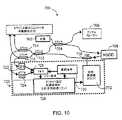
図10は、本発明による平衡検出を提供するための位相トラッカを有するSDOCTシステム700の例示の一実施形態を示す。この実施形態において、光源702は、スプリッタ704を通過する光を提供し、その光の一部をサンプルプローブ706に、また、その光の残りの部分を高速走査光学的遅延(RSOD)ライン708に送る。光は、RSOD708から位相変調器PM710に送られる。位相変調器PM710からの光は、スプリッタ712を通過し、そして、2つの追加されたスプリッタ714及び716を通過し、その出力の一部は、平衡検出出力としてスペクトル検出ユニット(図示しないが、本明細書中においていずれか他の箇所に記載)に送られ、また、その出力の残りは、位相トラッカ組立体720に送られる。位相トラッカ組立体720では、位相トラッカ検出器D1及びD2、722及び724が、スプリッタ714及び716の対の部分的な出力を受けて、信号をミキサ726に送ってエラー信号を生成する。処理ユニット728は、エラー信号を処理するが、この場合、オフセット電圧の合計生成によって、これは変調信号730に加算され、位相変調器ドライバ732用の出力が生成される。ボックス730に示す変調信号は、ミキサ726及び処理ユニット726に転送される。更に、干渉縞振幅は、位相トラッカがロックするには小さ過ぎる場合がある。他の選択肢として、コヒーレンス長がより長い二次光源をシステム700に接続して、より大きな干渉縞振幅を位相トラッカに提供し得る。FIG. 10 shows an exemplary embodiment of an
本発明は、図15A−Cに示す画像形成システムにおいて位相を追跡するための方法を提供する。本方法は、以下のステップを含む。即ち、(a)サンプルアームから受信された信号を測定するステップ、(b)信号の位相を大きくするステップ、(c)信号の少なくとも1つのピークにおいてXlと定義された信号の第1信号部を測定するステップ、(d)信号の位相を増分量だけ大きくするか又は小さくするか決定するステップ、(e)ステップ(d)の後、ステップ(d)に続いて、信号の第2信号部を測定するステップ、であり、もし信号がそのピークにある場合、その信号を再測定し、もし信号がそのピークになかった場合、ステップ(d)と(e)を繰り返す。The present invention provides a method for tracking phase in the imaging system shown in FIGS. 15A-C. The method includes the following steps. (A) measuring the signal received from the sample arm; (b) increasing the phase of the signal; (c) the first signal portion of the signal defined as X1 at at least one peak of the signal. (D) determining whether to increase or decrease the phase of the signal by an increment, (e) after step (d), following step (d), following the second signal portion of the signal If the signal is at its peak, measure the signal again, and if the signal is not at the peak, repeat steps (d) and (e).
本方法は、更に、ステップ(a)乃至(f)が、他の画像形成処理と並行して実行されることを含む。位相“φ”の調整は、A(x2−xl)と定義されるが、この場合、“A”は定数である。更に、オプションとして、ステップ(d)は、更に、A(x2−xl)が位相変調器の範囲内にあるか否かを判断するサブステップ(dl)と、A(x2−xl)がその範囲内にある場合、A(x2−xl)に等しい量だけφを変更するか、又は、A(x2−xl)がその範囲内にない場合、A(x2−xl)−m2πに等しい量だけφを変更するサブステップ(d2)と、を含み得るが、ここで、Mは、1より大きい整数である。更に、本方法は、オプションとして、信号xlを再測定するサブステップ(d3)を含み得る。The method further includes that steps (a) to (f) are performed in parallel with other image forming processes. The adjustment of the phase “φ” is defined as A (x2 −xl ), where “A” is a constant. Further optionally, step (d) further comprises substep (dl) for determining whether A (x2 -xl ) is within the range of the phase modulator, and A (x2 -xl ) Is within that range, change φ by an amount equal to A (x2 −xl ), or if A (x2 −xl ) is not within that range, A (x2 − and substep (d2) of changing φ by an amount equal to xl ) −m2π, where M is an integer greater than 1. Furthermore, the method optionally may include sub-step (d3) to re-measure the signal xl.
データ取得及び処理ユニット
一般的に、分光計によって収集されるデータは、等波長増分によってサンプリングされる。フーリエ変換は、しかしながら、z及びk空間(又は、t及びw)をリンクする。Kとλとの間の非線形的な関係のために、取得されたスペクトラムは、補間されて、kドメインにおいて均等に離間したサンプルを生成する。他の選択肢として、補間を用いる必要がなくなるように光がk空間において等間隔でサンプリングされるように、光は、検出アレイ上で分散し得る。他の選択肢として、検出アレイ間隔は、補間を用いる必要がなくなるように、kドメインにおいて均等に分散された光をサンプリングするように設計できる。最適な点分散関数を実現するために、干渉計のサンプル及び参照アームにおける分散は、好適には、平衡状態にすべきである。分散の不平衡は、デジタル処理によって補正し得る。Data Acquisition and Processing Unit In general, data collected by a spectrometer is sampled by equal wavelength increments. The Fourier transform, however, links z and k space (or t and w). Due to the non-linear relationship between K and λ, the acquired spectrum is interpolated to produce evenly spaced samples in the k domain. As another option, the light can be distributed on the detection array so that the light is sampled at equal intervals in k-space so that it is not necessary to use interpolation. As another option, the detection array spacing can be designed to sample light evenly distributed in the k-domain so that it is not necessary to use interpolation. In order to achieve an optimal point dispersion function, the dispersion in the interferometer sample and reference arm should preferably be balanced. Dispersion imbalance can be corrected by digital processing.
本発明は、血管中のアテローム硬化症斑点を特定するためのプローブを提供する。本プローブには、干渉計と、干渉計から受信された信号を複数の光周波数に分割するスペクトル分離ユニットと、スペクトル分離ユニットから受信された光周波数の少なくとも一部を検出できる検出器構成と、が含まれる。 The present invention provides a probe for identifying atherosclerotic spots in blood vessels. The probe includes an interferometer, a spectral separation unit that divides a signal received from the interferometer into a plurality of optical frequencies, a detector configuration that can detect at least a portion of the optical frequency received from the spectral separation unit, Is included.
更に、本発明は、治療薬を投与するための装置を提供する。本装置には、ハウジングに配置されたプローブであって、干渉計と、干渉計から受信された信号を複数の光周波数に分割するスペクトル分離ユニットと、スペクトル分離ユニットから受信された光周波数の少なくとも一部を検出できる検出器構成と、を含む前記プローブと、このプローブと協働する導管であって、治療薬を受け入れるための基端部と、所定の位置において治療薬を投与するための遠端部とを有し、前記位置は、プローブを用いて遠端部に近接する環境を画像化することによって決定される前記導管と、が含まれる。 Furthermore, the present invention provides an apparatus for administering a therapeutic agent. The apparatus includes a probe disposed in a housing, the interferometer, a spectrum separation unit that divides a signal received from the interferometer into a plurality of optical frequencies, and at least one of the optical frequencies received from the spectrum separation unit. A detector configuration capable of detecting a portion of the probe, a conduit cooperating with the probe, a proximal end for receiving the therapeutic agent, and a remote for administering the therapeutic agent in place. And the conduit wherein the position is determined by imaging an environment proximate to the far end using a probe.
本発明の例示の実施形態について、更に、説明のためだけに記載する次の例に関して以下に述べる。 Exemplary embodiments of the present invention are further described below with reference to the following examples, which are given for illustration only.
例
本発明による方法は、研究室での以下の実験によって検証された。EXAMPLE The method according to the invention was verified by the following experiment in the laboratory.
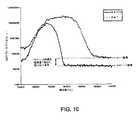
既設のOCTシステムにおいて、参照アーム光学パワーによるスペクトル密度から求められるショット雑音パワースペクトラムを測定した。この際、参照アームからのスペクトラムの2/3は、遮蔽され、また、実験的に、ショット雑音パワースペクトラムが、3分の1だけ低減されることが検証され、従って、スペクトラムが3つのスペクトル帯域に分割されると、ショット雑音は、3分の1だけ低減される(図16参照)ことが実証された。上の曲線(グレーの点線)は、1つの検出器によるOCT信号のパワースペクトラムを示す。下の曲線(実線)の場合、スペクトラムは、3分の1だけ制限され、信号対雑音比は、対応する3倍の改善があった。このデータは、実験的に生成され、回折格子ベースの二重通過パルスにおけるスペクトラムの2/3を遮蔽して、走査光学遅延ラインを高速に整形する。 In the existing OCT system, the shot noise power spectrum obtained from the spectral density by the reference arm optical power was measured. At this time, 2/3 of the spectrum from the reference arm is shielded, and experimentally it has been verified that the shot noise power spectrum is reduced by a third, so the spectrum is divided into 3 spectral bands. It has been demonstrated that shot noise is reduced by a third (see FIG. 16). The upper curve (grey dotted line) shows the power spectrum of the OCT signal by one detector. In the case of the lower curve (solid line), the spectrum was limited by a third, and the signal to noise ratio had a corresponding three-fold improvement. This data is generated experimentally and shields 2/3 of the spectrum in a grating-based double pass pulse to shape the scanning optical delay line at high speed.
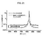
低反射率の物体をサンプルアームに挿入した。光源の全スペクトル幅を用いて、スペクトル密度の下半分において、サンプルと参照アーム光との間の干渉のパワースペクトラムを求めた。この際、光源スペクトラムの上半分は、参照アームにおいて遮蔽し、また、サンプルと参照アーム光との間の干渉パワースペクトラムの下1/3は、前の測定と同じ大きさを有する(図17参照)ことが検証された。この図は、信号振幅が、N=1及びN=1/3に対して、両者が重なり合う場合、等しいことを実証する。N=1/3の場合、等しい振幅の信号となり、また、N=1/3の場合、3分の1の低雑音になる(図参照6)という結果は、N波長帯域に分割すると、SNRは、N倍だけ大きくなることを実証する。 A low reflectivity object was inserted into the sample arm. Using the full spectral width of the light source, the power spectrum of the interference between the sample and the reference arm light was determined in the lower half of the spectral density. At this time, the upper half of the light source spectrum is shielded by the reference arm, and the lower third of the interference power spectrum between the sample and the reference arm light has the same size as the previous measurement (see FIG. 17). ) Was verified. This figure demonstrates that the signal amplitude is equal for N = 1 and N = 1/3 when both overlap. When N = 1/3, the signals have the same amplitude, and when N = 1/3, the noise is reduced by a third (see FIG. 6). Demonstrates that it is N times larger.
このことは、検出アームにおける光が2つのスペクトル帯域に分割される場合、単一の検出器のスペクトル帯域幅内におけるサンプルと参照アーム光との間の干渉のスペクトル密度は変化しないことを実証する。ショット雑音パワースペクトラムの減少を示す測定と組み合わせると、結論は、ショット雑音の低減は、検出アーム光を別々のスペクトル帯域に分割することによって実現し得るということである。 This demonstrates that if the light in the detection arm is split into two spectral bands, the spectral density of the interference between the sample and the reference arm light within the spectral bandwidth of a single detector does not change. . When combined with measurements that show a reduction in the shot noise power spectrum, the conclusion is that shot noise reduction can be achieved by dividing the detection arm light into separate spectral bands.
雑音低減の実験的検証
スペクトルドメインOCTにおける雑音低減を実証するために、高速走査光学遅延ライン(RSOD)を含むOCTシステムを参照アームに用いて、スペクトラムの幾つかの部分を遮蔽した。検出器信号を2.5Mサンプル/秒でデジタル化し、干渉縞情報のデジタル処理を行なった。まず、検出器への全ての光を遮蔽することによって、検出器の熱雑音密度を周波数の関数として測定した。第2に、参照アームパワーだけを検出器に入射させて、参照アームパワーのショット雑音密度を測定した。第3に、サンプル及び参照アーム光双方を検出器に入射させた。サンプルは、模型眼に搭載した単一の散乱面であり、2秒間で512の深度プロファイルを取得した。スペクトル密度の2乗に比例する(式(9)参照)パワー密度I(f)2を測定した。その後、参照アームにおけるスペクトラムの半分を遮蔽して、再度、サンプルアームを遮蔽することによって参照アームのショット雑音密度を測定し、サンプル及び参照アーム光が検出器に入射する時、パワー密度I(f)2を測定した。減算によって、ショット雑音及びパワー密度の熱雑音を補正した。熱雑音は、最低ショット雑音レベルより少なくとも3分の1小さい。Experimental verification of noise reduction To demonstrate noise reduction in the spectral domain OCT, an OCT system including a fast scanning optical delay line (RSOD) was used in the reference arm to occlude some parts of the spectrum. The detector signal was digitized at 2.5M samples / second and the interference fringe information was digitally processed. First, the thermal noise density of the detector was measured as a function of frequency by blocking all light to the detector. Second, only the reference arm power was incident on the detector, and the shot noise density of the reference arm power was measured. Third, both sample and reference arm light were incident on the detector. The sample was a single scattering surface mounted on the model eye, and a depth profile of 512 was acquired in 2 seconds. The power density I (f)2 that is proportional to the square of the spectral density (see equation (9)) was measured. Then, half of the spectrum in the reference arm is shielded and again the shot noise density of the reference arm is measured by shielding the sample arm. When the sample and reference arm light is incident on the detector, the power density I (f2 was measured. Shot noise and power density thermal noise were corrected by subtraction. Thermal noise is at least a third less than the lowest shot noise level.
図18は、スペクトラムが参照アームにおいて遮蔽された状態での全スペクトラムに対するパワー密度のグラフを周波数の関数として示す。実線は、全スペクトラムに対するパワー密度を示す。また、サンプルアームが遮蔽されている間に測定されたショット雑音レベルも示す。点線は、スペクトラムの半分がサンプルアームにおいて遮蔽されている状態のパワー密度を示す。また、サンプルアームが遮蔽されている間に測定されたショット雑音レベルも示す。図18は、ショット雑音レベルが、参照アームにおけるスペクトラム半分遮蔽することによって2分の1だけ低減されたことを実証する。同時に、参照アームにおいて遮蔽されなかった波長に対応する周波数の信号は同じままであった。 FIG. 18 shows a graph of power density as a function of frequency for the entire spectrum with the spectrum shielded at the reference arm. The solid line shows the power density for the entire spectrum. It also shows the shot noise level measured while the sample arm is shielded. The dotted line indicates the power density with half of the spectrum being shielded at the sample arm. It also shows the shot noise level measured while the sample arm is shielded. FIG. 18 demonstrates that the shot noise level was reduced by a factor of 2 by shielding half the spectrum in the reference arm. At the same time, the signal at the frequency corresponding to the wavelength that was not shielded in the reference arm remained the same.
測定された結果の概要を示す図18から明らかなように、ショット雑音密度は、参照アームにおけるスペクトラムを半分遮蔽することによって約2分の1だけ低減される。図19は、ショット雑音レベルを対応する信号から減算した後、参照アームにおいて遮蔽されなかった波長に対応する周波数に対するパワー密度は同じままであったことを示す。このことは、全参照アームパワーがスペクトラムを半分遮蔽することによって2分の1だけ低減される時、ショット雑音密度は、2分の1だけ低減され、一方、参照アームにおいて遮蔽されなかった波長に対する信号パワー密度は変化しないことを実証する。 As is apparent from FIG. 18, which shows an overview of the measured results, the shot noise density is reduced by about one-half by shielding the spectrum in the reference arm half. FIG. 19 shows that after subtracting the shot noise level from the corresponding signal, the power density for the frequency corresponding to the wavelength that was not shielded in the reference arm remained the same. This means that when the total reference arm power is reduced by a factor of two by shielding the spectrum by half, the shot noise density is reduced by a factor of two, while against the wavelength that was not shielded in the reference arm. Demonstrate that the signal power density does not change.
図19は、全スペクトラム及び参照アームにおいて遮蔽された半分のスペクトラムに対するパワー密度の平方根のグラフを周波数の関数として示す。実線は、それぞれのショット雑音を減算した後のスペクトラムを示す。点線は、それぞれのショット雑音を減算した後の半分のスペクトラムを示す。図13は、それぞれのショット雑音の影響を減算した後、参照アームにおいて遮蔽されなかった波長に対応する信号周波数は同じままであったことを実証する。 FIG. 19 shows a graph of the square root of power density as a function of frequency for the full spectrum and half of the spectrum shielded in the reference arm. The solid line shows the spectrum after subtracting each shot noise. The dotted line shows the half spectrum after subtracting each shot noise. FIG. 13 demonstrates that after subtracting the effect of each shot noise, the signal frequency corresponding to the wavelength that was not shielded in the reference arm remained the same.
次の実験は、更に、幾つかの検出器に渡って検出アームにおいてスペクトラムを分散することによって、また、各検出器の信号を選択的に帯域通過フィルタ処理することによって、SNRが大きくなることを実証する。図13に示す回折格子によって、検出アーム光を4つの検出器に渡って分散し、トランスインピーダンス増幅器によって、600kHzの帯域幅で検出器信号を別々に増幅して、同時にデジタル化した。 The next experiment further shows that the SNR can be increased by spreading the spectrum in the detection arm across several detectors, and by selectively band-pass filtering each detector signal. Demonstrate. With the diffraction grating shown in FIG. 13, the detection arm light was dispersed over four detectors, and the detector signal was separately amplified with a bandwidth of 600 kHz by a transimpedance amplifier and simultaneously digitized.
図13は、本発明に基づくスペクトルドメインOCTによるSNR改善を実証するために用いられる例示の装置構成を示す概略図である。参照アーム106の走査は、高速走査光学遅延ライン(RSOD)120で行なった。アレイ検出器114からの個々の信号は、トランスインピーダンス増幅器によって増幅され、チャネル当たり2.5MHzの4チャネルA/Dボードによってデジタル化され、コンピュータメモリ(図示せず)に記憶された。 FIG. 13 is a schematic diagram illustrating an example apparatus configuration used to demonstrate SNR improvement with spectral domain OCT according to the present invention. Scanning of the
最初に、4つの全検出器の熱雑音密度を測定した。第2に、各検出器チャネル116における参照アーム光のショット雑音密度を測定した。第3に、検出器114にサンプル及び参照アーム光双方を入射させた。サンプル130は、模型眼に搭載した単一の散乱面であり、2秒間で512の深度プロファイルを取得した。各検出器チャネル114におけるパワー密度I(f)2を測定した。その後、4つの検出器114の信号を合計し、合成パワー密度I(f)2を求めた。その結果を図20に示す。図20が実証することは、ショット雑音は、全てのチャネルの合計と比較して各個々のチャネルでは小さいが、それぞれの帯域幅内における個々のチャネルでのパワー密度I(f)2は、4つのチャネルのコヒーレントな合計のパワー密度I(f)2にほぼ等しいことである。First, the thermal noise density of all four detectors was measured. Second, the shot noise density of the reference arm light in each
図20は、図13の4つの別々の検出器116に対するパワー密度のグラフを示す。検出アームにおけるスペクトラムは、回折格子520によって、4つの別々の検出器116上で分散した。各個々の検出器116に対するショット雑音レベルは、4つの検出器チャネルのコヒーレントな合計に対するものより大幅に小さい。画像の上にある棒線は、個々のチャネル及びコヒーレントに合計されたチャネルに適用されて、図21を生成した信号通過帯域を示す。 FIG. 20 shows a power density graph for the four
図21において、4つの全検出チャネルの直接的な合計及びコヒーレントな合計の双方に対するコヒーレンス包絡線の2乗を示すが、これは、帯域幅をそれぞれの検出器信号の中心周波数を中心にした状態で、各検出器チャネルをデジタル的に帯域通過フィルタ処理した後のものである。図21は、4つの検出器信号の直接の合計及び帯域通過フィルタ処理されたコヒーレントな合計の干渉縞信号I(t)は、実質的に同じコヒーレンス包絡線ピーク値になる一方で、4つの検出器信号の帯域通過フィルタ処理されたコヒーレントな合計は、直接的なコヒーレントな合計より大幅に小さい雑音レベルを呈することを示す。各個々のチャネルの通過帯域は、全信号の通過帯域の3分の1より若干大きい(通過帯域は図20に示す)ため、2.87倍のSNRの増加が予測された。雑音レベルは、2.8分の1だけ低下した。しかしながら、また、帯域通過フィルタ処理によって、信号は、1.12分の1だけ若干減少し、SNRは、実効的に2.5倍増加した。 In FIG. 21, the square of the coherence envelope for both the direct sum and the coherent sum of all four detection channels is shown, which shows the bandwidth centered on the center frequency of each detector signal. Thus, each detector channel is digitally bandpass filtered. FIG. 21 shows that the direct sum of the four detector signals and the bandpass filtered coherent sum interference fringe signal I (t) result in substantially the same coherence envelope peak value while the four detections The bandpass filtered coherent sum of the detector signal is shown to exhibit a noise level that is significantly less than the direct coherent sum. Since the passband of each individual channel is slightly larger than one third of the total signal passband (passband is shown in FIG. 20), a 2.87-fold increase in SNR was expected. The noise level was reduced by a factor of 2.8. However, the bandpass filtering also reduced the signal slightly by 1.12 and effectively increased the SNR by a factor of 2.5.
これらの実験は、検出アームにおいて光をスペクトル分散すると、大幅なSNRの利点を提供し得ることを明瞭に実証する。 These experiments clearly demonstrate that spectral dispersion of light in the detection arm can provide significant SNR benefits.
図21は、コヒーレントに合計されたチャネル、及び各チャネルを帯域通過フィルタ処理した後のコヒーレントに合計されたチャネルに対するコヒーレンス包絡線を示す。実線は、チャネルの合計である。点線は、チャネルの帯域フィルタ処理された合計である。図21は、幾つかの個々の検出器に渡って検出アームにおける信号をスペクトル的に分散することによって実現し得る信号対雑音利得を明瞭に実証する。本例において、雑音レベルは、約2.8分の1だけ低減された。コヒーレンスピークが、帯域通過フィルタによってフィルタ処理で除去された何らかの残留信号部のために1.12分の1だけ減少したため、実際のSNRの改善は、2.5であった。 FIG. 21 shows coherent summed channels and the coherence envelope for the coherent summed channels after bandpass filtering each channel. The solid line is the sum of the channels. The dotted line is the band-filtered sum of the channel. FIG. 21 clearly demonstrates the signal-to-noise gain that can be achieved by spectrally dispersing the signal in the detection arm across several individual detectors. In this example, the noise level was reduced by about 2.8. The actual SNR improvement was 2.5 because the coherence peak was reduced by a factor of 1.12 due to any residual signal that was filtered out by the bandpass filter.
本発明の数例の実施形態のみについてこれまで詳述したが、当業者は、本発明の新規の教示内容及び利点から実質的に逸脱することなく、数多くの変更が、例示の実施形態において可能であることを理解されるであろう。従って、このような全ての変更は、以下の請求項で定義される本発明の範囲に包含されるものとする。更に、本明細書中において参照したあらゆる特許、出願及び公報は、それら全体が引用され参照されていることに留意されたい。 Although only a few example embodiments of the present invention have been described in detail so far, those skilled in the art will be able to make numerous changes in the illustrated embodiments without substantially departing from the novel teachings and advantages of the present invention. It will be understood that. Accordingly, all such modifications are intended to be included within the scope of this invention as defined in the following claims. Furthermore, it should be noted that all patents, applications and publications referred to in this specification are cited and referenced in their entirety.
100・・・上位レベルシステム、102・・・干渉計、104・・・光源アーム、106・・・サンプルアーム、108・・・参照アーム、110・・・検出アーム、116・・・増幅器、124・・・デジタル帯域通過フィルタ処理(BPF)ユニット、130・・・サンプル
DESCRIPTION OF
Claims (102)
Translated fromJapanesea)干渉計と、
b)前記干渉計から受信された信号を複数の光周波数に分割するスペクトル分離ユニットと、
c)複数の検出器であって、各検出器が前記スペクトル分離ユニットから受信された前記光周波数の少なくとも一部を検出可能な前記複数の検出器と、
が含まれる装置。An apparatus for optical imaging, comprising:
a) an interferometer;
b) a spectral separation unit for dividing the signal received from the interferometer into a plurality of optical frequencies;
c) a plurality of detectors, each detector capable of detecting at least part of the optical frequency received from the spectral separation unit;
The device that contains.
d)電磁放射の光源から受信されたエネルギを参照信号及びサンプル信号に分割するための手段と、
e)参照アーム光を提供する参照アームと、
f)サンプルアーム光を提供するサンプルアームと、
g)前記参照アーム光及び前記サンプルアーム光を再合成するための手段と、
が含まれる装置。The apparatus of claim 1, wherein the interferometer is
d) means for splitting the energy received from the source of electromagnetic radiation into a reference signal and a sample signal;
e) a reference arm that provides a reference arm light;
f) a sample arm that provides sample arm light;
g) means for recombining the reference arm light and the sample arm light;
The device that contains.
a)第1走査ラインを取得し、
b)サンプルの表面位置“S”を特定し、
c)サンプルの最適な走査範囲“R”を特定し、
d)出力を提供するために参照アーム遅延波形を修正し、
e)参照アームに前記出力を出力し、
f)前記画像が完全であるかどうか判断し、
g)前記画像が完全でない場合、次の走査ラインに移動し、又は前記画像が完全である場合、前記メモリ記憶装置に記憶された前記表面Sデータ及び前記波形データを用いて、前記画像を再マッピングするためのプロセッサユニットを含む装置。25. The apparatus of claim 24, wherein the means for automatic lateral distance is
a) acquiring a first scan line;
b) Identify the surface position “S” of the sample,
c) identify the optimal scan range “R” of the sample;
d) modify the reference arm delay waveform to provide an output;
e) output the output to the reference arm;
f) determine if the image is complete,
g) If the image is not complete, move to the next scan line, or if the image is complete, replay the image using the surface S data and the waveform data stored in the memory storage. A device comprising a processor unit for mapping.
a)第1走査ラインを取得し、
b)サンプルの表面位置“S”を特定し、
c)サンプルの最適な走査範囲“R”を特定し、
d)出力を提供するために参照アーム遅延波形を修正し、
e)参照アームに前記出力を出力し、
f)前記画像が完全かどうかを判断し、
g)前記画像が完全でない場合、次の走査ラインに移動し、又は、前記画像が完全である場合、前記メモリ記憶装置に記憶された前記表面Sデータ及び前記波形データを用いて、前記画像を再マッピングするための自動測距プロセッサユニットを含む装置。The apparatus of claim 46, further comprising:
a) acquiring a first scan line;
b) Identify the surface position “S” of the sample,
c) identify the optimal scan range “R” of the sample;
d) modify the reference arm delay waveform to provide an output;
e) output the output to the reference arm;
f) determine if the image is complete,
g) If the image is not complete, move to the next scan line, or if the image is complete, use the surface S data and the waveform data stored in the memory storage to An apparatus including an automatic ranging processor unit for remapping.
a)干渉計と、
b)参照アーム遅延を生成するための手段と、
c)前記参照アーム遅延を生成するための前記手段から受信された信号を利用する前記干渉計から受信された信号を複数の光周波数に分割するスペクトル分離ユニットと、
d)複数の検出器であって、各検出器が前記スペクトル分離ユニットから受信された前記光周波数の少なくとも一部を検出可能な前記複数の検出器と、
が含まれる装置。An apparatus for optical imaging, comprising:
a) an interferometer;
b) means for generating a reference arm delay;
c) a spectral separation unit that divides the signal received from the interferometer into a plurality of optical frequencies that utilizes the signal received from the means for generating the reference arm delay;
d) a plurality of detectors, each detector capable of detecting at least part of the optical frequency received from the spectral separation unit;
The device that contains.
a)少なくとも1つの位相変調器と、
b)干渉計と、
c)少なくとも1つの光源と、
d)少なくとも1つの検出器と、
e)フィードバック・ループを生成するための信号処理装置と、
が含まれる装置。An apparatus for tracking phase to reduce signal attenuation due to instability of interference fringes,
a) at least one phase modulator;
b) an interferometer;
c) at least one light source;
d) at least one detector;
e) a signal processing device for generating a feedback loop;
The device that contains.
a)前記サンプルアームから受信された信号を測定する段階と、
b)前記信号の位相を大きくする段階と、
c)前記信号の少なくとも1つのピークでx1と定義された前記信号の第1信号部分を測定する段階と、
d)一定量だけ前記信号の位相を大きくするか又は小さくするか判断する段階と、
e)段階(d)の後、段階d)に続き前記信号の第2信号部分を測定する段階と、
f)前記信号がそのピークである場合、前記信号を再測定し、前記信号がそのピークでない場合、段階d)及びe)を繰り返す段階と、
が含まれる方法。A method for tracking phase in an imaging system comprising:
a) measuring a signal received from the sample arm;
b) increasing the phase of the signal;
c) measuring a first signal portion of the signal defined as x1 at at least one peak of the signal;
d) determining whether to increase or decrease the phase of the signal by a fixed amount;
e) after step (d), following step d), measuring a second signal portion of said signal;
f) if the signal is at its peak, re-measure the signal, and if the signal is not at its peak, repeat steps d) and e);
Include methods.
a)位相追跡下位組立体であって
i)位相変調器ドライバと、
ii)位相変調器からの変調周波数を用いて少なくとも1つの検出器からの信号を混合するように、また、それからエラー信号を生成するように構成されたミキサと、
iii)前記エラー信号を処理するように、また、オフセット電圧を生成するように構成された処理ユニットと、
が含まれる前記位相追跡下位組立体を含む装置。In an apparatus for tracking a phase with an extended lock range,
a) a phase tracking subassembly; i) a phase modulator driver;
ii) a mixer configured to mix the signal from the at least one detector using the modulation frequency from the phase modulator and to generate an error signal therefrom;
iii) a processing unit configured to process the error signal and to generate an offset voltage;
Including the phase tracking subassembly.
a)複数の検出器と、位相変調器ドライバと、位相変調器からの変調周波数で前記検出器からの信号をミキシングし、また、そこからエラー信号を生成するためのミキサと、前記エラー信号を処理するように、また、オフセット電圧を生成するように構成された処理ユニットと、を含む位相追跡構成が含まれる装置。An apparatus for spectral domain optical coherence tomography imaging with phase tracking comprising:
a) a plurality of detectors, a phase modulator driver, a mixer for mixing a signal from the detector with a modulation frequency from the phase modulator, and generating an error signal therefrom; and the error signal An apparatus that includes a phase tracking arrangement that includes a processing unit configured to process and to generate an offset voltage.
a)電磁放射光源を提供する段階と、
b)前記光源をビームスプリッタを介して導く段階であって、前記光の一部が、参照アーム遅延機構に導かれ、また、前記光の一部が、サンプルに導かれるように前記光源を導く前記段階と、
c)前記サンプルから反射されて戻った前記光の前記部分及び前記参照アーム遅延機構からの前記光の前記部分をスペクトル多重処理組立体を通過させる段階と、
d)前記スペクトル多重処理組立体からの前記光を複数の固有周波数スペクトル帯域信号に分割する段階と、
e)前記各帯域信号を少なくとも1つの検出器に導く段階と、
f)前記光信号を処理する段階と、
g)前記処理された光信号に基づき、干渉計の少なくとも1つの前記アーム内からの縦方向の情報を再構築する段階と、
が含まれる方法。A method for increasing sensitivity and signal-to-noise ratio in OCT and LCI imaging,
a) providing an electromagnetic radiation source;
b) guiding the light source through a beam splitter, wherein a part of the light is guided to a reference arm delay mechanism and a part of the light is guided to a sample. Said step;
c) passing the portion of the light reflected back from the sample and the portion of the light from the reference arm delay mechanism through a spectral multiplexing assembly;
d) splitting the light from the spectral multiplexing assembly into a plurality of natural frequency spectral band signals;
e) directing each band signal to at least one detector;
f) processing the optical signal;
g) reconstructing longitudinal information from within the at least one arm of an interferometer based on the processed optical signal;
Include methods.
a)干渉計と、
b)前記干渉計から受信された信号を複数の固有周波数に分割するスペクトル分離ユニットと、
c)複数の検出器であって、各検出器が前記スペクトル分離ユニットから受信されたそれぞれの周波数信号を検出可能であり、前記複数の各検出器は、それらに付随した少なくとも1つのトランスインピーダンス増幅器を有し、また、前記複数の各検出器は、それらに付随した少なくとも1つの帯域通過フィルタを有する前記複数の検出器と、
d)前記複数の検出器から受信された信号を処理するための処理構成と、
e)前記処理された信号を表示するための表示構成と、
が含まれる装置。A probe useful for optical coherence tomography imaging,
a) an interferometer;
b) a spectral separation unit for dividing the signal received from the interferometer into a plurality of natural frequencies;
c) a plurality of detectors, each detector being capable of detecting a respective frequency signal received from the spectral separation unit, wherein each of the plurality of detectors is associated with at least one transimpedance amplifier; And each of the plurality of detectors has at least one bandpass filter associated with the plurality of detectors;
d) a processing configuration for processing signals received from the plurality of detectors;
e) a display arrangement for displaying the processed signal;
The device that contains.
a)可撓性カテーテル本体であって、それを貫通する少なくとも1つの孔と、基端部及び遠端部とを有する前記可撓性カテーテル本体と、
b)患者の体内に配置された時、前記組織の表面から離れて保持されるように、前記カテーテル本体中を延在する光学プローブであって、その基端部において電気光学画像解析システムに接続するように構成され、
i)少なくとも1つの光ファイバと、
ii)レンズ要素と、
iii)前記光ファイバからの光を前記組織表面に透過し、また、前記組織表面からの反射光を受光し得るプリズムと、を含む前記光学プローブと、
が含まれる装置。An apparatus for optical coherence tomography image formation comprising:
a) a flexible catheter body having at least one hole therethrough and a proximal end and a distal end;
b) an optical probe extending through the catheter body to be held away from the surface of the tissue when placed in the patient's body, connected at its proximal end to an electro-optic image analysis system Configured to
i) at least one optical fiber;
ii) a lens element;
iii) a prism capable of transmitting light from the optical fiber to the tissue surface and receiving reflected light from the tissue surface;
The device that contains.
前記プリズムをその縦軸を中心にして機械的に回転させるための前記プリズムに付随するケーブルが含まれる方法。The method of claim 72, further comprising:
A method comprising a cable associated with the prism for mechanically rotating the prism about its longitudinal axis.
a)干渉計と、
b)複数の検出器であって、各検出器が、それらに付随した少なくとも1つのトランスインピーダンス増幅器を有し、また、それらに付随した少なくとも1つの帯域通過フィルタを有する前記複数の検出器と、
c)前記複数の検出器から受信された信号を処理するための処理構成と、
d)前記処理された信号を表示するための表示構成と、
が含まれる装置。An apparatus for optical coherence tomography image formation, comprising:
a) an interferometer;
b) a plurality of detectors, each detector having at least one transimpedance amplifier associated therewith and having at least one bandpass filter associated therewith;
c) a processing configuration for processing signals received from the plurality of detectors;
d) a display arrangement for displaying the processed signal;
The device that contains.
a)干渉計からの少なくとも1つの電磁気信号を受信するように、また、前記少なくとも1つの電磁気信号を複数のスペクトル帯域に分離するように構成されたスペクトル分離構成であって、前記少なくとも1つの電磁気信号は、前記サンプルの前記少なくとも1つの部分の特性に関連する前記スペクトル分離構成と、
b)前記スペクトル分離構成から受信された少なくとも1つのスペクトル帯域を検出するように構成され、また、前記サンプルの前記少なくとも1つの部分の少なくとも1つの部分を画像形成するために用いられる合成信号を生成するように構成された検出構成と、が含まれる装置。An apparatus for optically imaging at least one part of a sample,
a) A spectral separation arrangement configured to receive at least one electromagnetic signal from an interferometer and to separate the at least one electromagnetic signal into a plurality of spectral bands, the at least one electromagnetic A signal comprising the spectral separation configuration associated with characteristics of the at least one portion of the sample;
b) generating a composite signal configured to detect at least one spectral band received from the spectral separation configuration and used to image at least one portion of the at least one portion of the sample; And a detection configuration configured to.
a)前記デジタル信号を受信するように、また、前記デジタル信号を帯域通過フィルタ処理するように構成された複数のフィルタを含む装置。78. The apparatus of claim 77, wherein the detector digitizes a detected spectral band into a digital signal, and further
a) An apparatus comprising a plurality of filters configured to receive the digital signal and to band-pass filter the digital signal.
a)前記デジタル信号を受信するように、また、前記サンプルの前記少なくとも1つの部分における内部の前記少なくとも1つの部分に関連するデータを生成するように構成された処理構成を含む装置。79. The apparatus of claim 78, wherein the at least one electromagnetic signal includes information about at least one portion within the at least one portion of the sample, and further
a) an apparatus comprising a processing arrangement configured to receive the digital signal and to generate data associated with the at least one portion within the at least one portion of the sample;
a)検出構成からの前記少なくとも1つの電磁気信号のスペクトル帯域に対応する信号を受信する段階であって、前記検出構成は、スペクトル分離構成によって前記少なくとも1つの電磁気信号から分離される前記スペクトル帯域を検出し、前記スペクトル分離構成は、干渉計から前記少なくとも1つの電磁気信号を受信し、前記少なくとも1つの電磁気信号は、前記サンプルの前記少なくとも1つの部分の特性に関連する前記段階と、
前記受信信号に対応する情報に基づき前記データを生成する段階と、
が含まれる論理構成。In a logical configuration providing data related to optical imaging of at least one portion of a sample, the logical configuration is configured such that when executed by the processing configuration, the processing configuration performs the following steps: The stage includes
a) receiving a signal corresponding to a spectral band of the at least one electromagnetic signal from a detection configuration, wherein the detection configuration includes the spectral band separated from the at least one electromagnetic signal by a spectral separation configuration; Detecting, wherein the spectral separation configuration receives the at least one electromagnetic signal from an interferometer, the at least one electromagnetic signal being associated with a characteristic of the at least one portion of the sample;
Generating the data based on information corresponding to the received signal;
A logical configuration that contains
a)検出構成からの前記少なくとも1つの電磁気信号のスペクトル帯域に対応する信号を受信する段階であって、前記検出構成は、スペクトル分離構成によって前記少なくとも1つの電磁気信号から分離される前記スペクトル帯域を検出し、前記スペクトル分離構成は、干渉計から前記少なくとも1つの電磁気信号を受信し、前記少なくとも1つの電磁気信号は、前記サンプルの前記少なくとも1つの部分の特性に関連する前記段階と、
前記受信信号に対応する情報に基づき前記データを生成する段階と、
が含まれる方法。A method for providing data related to optical imaging of at least one portion of a sample comprising:
a) receiving a signal corresponding to a spectral band of the at least one electromagnetic signal from a detection configuration, wherein the detection configuration includes the spectral band separated from the at least one electromagnetic signal by a spectral separation configuration; Detecting, wherein the spectral separation configuration receives the at least one electromagnetic signal from an interferometer, the at least one electromagnetic signal being associated with a characteristic of the at least one portion of the sample;
Generating the data based on information corresponding to the received signal;
Include methods.
a)検出構成からの前記少なくとも1つの電磁気信号のスペクトル帯域に対応する信号を受信する段階であって、前記検出構成は、スペクトル分離構成によって前記少なくとも1つの電磁気信号から分離される前記スペクトル帯域を検出し、前記スペクトル分離構成は、干渉計から前記少なくとも1つの電磁気信号を受信し、前記少なくとも1つの電磁気信号は、前記サンプルの前記少なくとも1つの部分の特性に関連する前記段階と、
前記受信信号に対応する情報に基づき前記データを生成する段階と、
が含まれる記憶媒体。A storage medium having executable instructions thereon for providing data related to optical imaging of at least one portion of a sample, said executable when said executable instructions are executed by a processing system Instructions are configured such that the processing system performs the following steps:
a) receiving a signal corresponding to a spectral band of the at least one electromagnetic signal from a detection configuration, wherein the detection configuration includes the spectral band separated from the at least one electromagnetic signal by a spectral separation configuration; Detecting, wherein the spectral separation configuration receives the at least one electromagnetic signal from an interferometer, the at least one electromagnetic signal being associated with a characteristic of the at least one portion of the sample;
Generating the data based on information corresponding to the received signal;
A storage medium containing
a)処理構成であって、
b)前記少なくとも1つの信号に関連する情報を受信する段階と、
c)前記少なくとも1つの信号の前記位相を調整する段階と、
d)前記少なくとも1つの信号の信号部の位置を取得する段階と、
e)前記信号部の前記位置が、前記少なくとも1つの信号のピークから所定の距離を越えて提供される場合、前記少なくとも1つの信号の少なくとも1つの特性を修正する段階と、
f)前記少なくとも1つの信号が、前記ピークからの前記所定の距離内になるまで段階(d)及び(e)を繰り返す段階と、
に対応するように構成された前記処理構成が含まれる装置。In an apparatus for tracking the phase of at least one signal to reduce attenuation of at least one electromagnetic signal due to instability of the interference fringes,
a) a processing configuration comprising:
b) receiving information related to the at least one signal;
c) adjusting the phase of the at least one signal;
d) obtaining the position of the signal portion of the at least one signal;
e) modifying at least one characteristic of the at least one signal if the position of the signal portion is provided beyond a predetermined distance from a peak of the at least one signal;
f) repeating steps (d) and (e) until the at least one signal is within the predetermined distance from the peak;
An apparatus including the processing configuration configured to correspond to the above.
a)前記少なくとも1つの信号に関連する情報を受信する段階と、
b)前記少なくとも1つの信号の前記位相を調整する段階と、
c)前記少なくとも1つの信号の信号部の位置を取得する段階と、
d)前記信号部の前記位置が、前記少なくとも1つの信号のピークから所定の距離より離れている場合、前記少なくとも1つの信号の少なくとも1つの特性を修正する段階と、
e)前記少なくとも1つの信号が、前記ピークからの前記所定の距離内になるまで段階(d)及び(e)を繰り返す段階と、
が含まれる論理構成。In a logic configuration for tracking the phase of the at least one signal to reduce attenuation of at least one electromagnetic signal due to instability of the interference fringes, the logic configuration, when executed by the processing configuration, when the processing is performed by the processing configuration The configuration is configured to perform the following steps, which include:
a) receiving information related to the at least one signal;
b) adjusting the phase of the at least one signal;
c) obtaining the position of the signal portion of the at least one signal;
d) modifying the at least one characteristic of the at least one signal if the position of the signal portion is more than a predetermined distance from the peak of the at least one signal;
e) repeating steps (d) and (e) until the at least one signal is within the predetermined distance from the peak;
Logical configuration that contains
a)前記少なくとも1つの信号に関連する情報を受信する段階と、
b)前記少なくとも1つの信号の前記位相を調整する段階と、
c)前記少なくとも1つの信号の信号部の位置を取得する段階と、
d)前記信号部の前記位置が、前記少なくとも1つの信号のピークから所定の距離より離れている場合、前記少なくとも1つの信号の少なくとも1つの特性を修正する段階と、
e)前記少なくとも1つの信号が、前記ピークからの前記所定の距離内にある位置より遠い位置に到達するまで段階(d)及び(e)を繰り返す段階と、
が含まれる方法。A method for tracking the phase of at least one signal to reduce attenuation of at least one electromagnetic signal due to instability of the fringe,
a) receiving information related to the at least one signal;
b) adjusting the phase of the at least one signal;
c) obtaining the position of the signal portion of the at least one signal;
d) modifying the at least one characteristic of the at least one signal if the position of the signal portion is more than a predetermined distance from the peak of the at least one signal;
e) repeating steps (d) and (e) until the at least one signal reaches a position farther than a position within the predetermined distance from the peak;
Include methods.
a)前記少なくとも1つの信号に関連する情報を受信する段階と、
b)前記少なくとも1つの信号の前記位相を調整する段階と、
c)前記少なくとも1つの信号の信号部の位置を取得する段階と、
d)前記信号部の前記位置が、前記少なくとも1つの信号のピークから所定の距離だけ離れている場合、前記少なくとも1つの信号の少なくとも1つの特性を修正する段階と、
e)前記少なくとも1つの信号が、前記ピークからの前記所定の距離内になるまで段階(d)及び(e)を繰り返す段階と、
が含まれる記憶媒体。A storage medium comprising executable instructions thereon for tracking the phase of the at least one signal so as to reduce attenuation of the at least one electromagnetic signal due to instability of the fringes When an instruction is executed by a processing system, the executable instruction is configured such that the processing system performs the following steps:
a) receiving information related to the at least one signal;
b) adjusting the phase of the at least one signal;
c) obtaining the position of the signal portion of the at least one signal;
d) modifying the at least one characteristic of the at least one signal if the position of the signal portion is a predetermined distance away from the peak of the at least one signal;
e) repeating steps (d) and (e) until the at least one signal is within the predetermined distance from the peak;
A storage medium containing
a)前記少なくとも1つの電磁気信号から分離された複数のスペクトル帯域を含む少なくとも1つの第1信号を取得する検出構成と、
b)変調周波数を有する位相変調器ドライバであって、少なくとも1つの第2信号を生成するように前記変調周波数に基づき、前記少なくとも1つの第1信号を変調するように構成された前記位相変調器ドライバと、
c)合成信号を生成するように前記少なくとも1つの第1信号と前記少なくとも1つの第2信号とをミキシングするように構成されたミキサと、
d)前記合成信号に基づき、オフセット電圧を生成するように構成された処理構成と、が含まれる装置。An apparatus for tracking the phase of at least one electromagnetic signal associated with at least one portion of a sample, comprising:
a) a detection arrangement for obtaining at least one first signal comprising a plurality of spectral bands separated from said at least one electromagnetic signal;
b) a phase modulator driver having a modulation frequency, the phase modulator configured to modulate the at least one first signal based on the modulation frequency to generate at least one second signal A driver,
c) a mixer configured to mix the at least one first signal and the at least one second signal to generate a composite signal;
and d) a processing arrangement configured to generate an offset voltage based on the combined signal.
a)前記少なくとも1つの電磁気信号から分離された複数のスペクトル帯域を含む少なくとも1つの第1信号を取得する段階と、
b)少なくとも1つの第2信号を生成するように変調構成の変調周波数に基づき、前記少なくとも1つの第1信号を変調する段階と、
c)合成信号を生成するように前記少なくとも1つの第1信号と前記少なくとも1つの第2信号とをミキシングする段階と、
d)前記合成信号に基づき、オフセット電圧を生成する段階と、が含まれる方法。A logic configuration for tracking the phase of at least one electromagnetic signal associated with at least one portion of a sample, wherein when the logic configuration is executed by a processing configuration, the processing configuration performs the following steps: The stage is configured as follows:
a) obtaining at least one first signal comprising a plurality of spectral bands separated from said at least one electromagnetic signal;
b) modulating the at least one first signal based on a modulation frequency of a modulation configuration to generate at least one second signal;
c) mixing the at least one first signal and the at least one second signal to generate a composite signal;
d) generating an offset voltage based on the combined signal.
a)前記少なくとも1つの電磁気信号から分離された複数のスペクトル帯域を含む少なくとも1つの第1信号を取得する段階と、
b)少なくとも1つの第2信号を生成するように変調構成の変調周波数に基づき、前記少なくとも1つの第1信号を変調する段階と、
c)合成信号を生成するように前記少なくとも1つの第1信号と前記少なくとも1つの第2信号とをミキシングする段階と、
d)前記合成信号に基づき、オフセット電圧を生成する段階と、が含まれる方法。A method for tracking the phase of at least one electromagnetic signal associated with at least one portion of a sample, comprising:
a) obtaining at least one first signal comprising a plurality of spectral bands separated from said at least one electromagnetic signal;
b) modulating the at least one first signal based on a modulation frequency of a modulation configuration to generate at least one second signal;
c) mixing the at least one first signal and the at least one second signal to generate a composite signal;
d) generating an offset voltage based on the combined signal.
a)前記少なくとも1つの電磁気信号から分離された複数のスペクトル帯域を含む少なくとも1つの第1信号を取得する段階と、
b)少なくとも1つの第2信号を生成するように変調構成の変調周波数に基づき、前記少なくとも1つの第1信号を変調する段階と、
c)合成信号を生成するように前記少なくとも1つの第1信号と前記少なくとも1つの第2信号とをミキシングする段階と、
d)前記合成信号に基づき、オフセット電圧を生成する段階と、が含まれる記憶媒体。A storage medium comprising executable instructions thereon for tracking the phase of the at least one signal so as to reduce attenuation of the at least one electromagnetic signal due to instability of the fringes When an instruction is executed by a processing system, the executable instruction is configured such that the processing system performs the following steps:
a) obtaining at least one first signal comprising a plurality of spectral bands separated from said at least one electromagnetic signal;
b) modulating the at least one first signal based on a modulation frequency of a modulation configuration to generate at least one second signal;
c) mixing the at least one first signal and the at least one second signal to generate a composite signal;
d) generating an offset voltage based on the combined signal.
a)干渉計からの少なくとも1つの電磁気信号を受信するように、また、前記少なくとも1つの電磁気信号を複数のスペクトル帯域に分離するように構成されたスペクトル分離構成であって、前記少なくとも1つの電磁気信号は、前記サンプルの前記少なくとも1つの部分の特性に関連する前記スペクトル分離構成と、
b)前記スペクトル分離構成から受信された少なくとも1つのスペクトル帯域を検出するように構成され、また、前記データに用いるための合成信号を生成するように構成された検出構成と、が含まれる装置。An apparatus for providing data relating to at least one portion of a sample,
a) a spectral separation arrangement configured to receive at least one electromagnetic signal from an interferometer and to separate the at least one electromagnetic signal into a plurality of spectral bands, the at least one electromagnetic A signal comprising the spectral separation configuration associated with characteristics of the at least one portion of the sample;
and b) a detection configuration configured to detect at least one spectral band received from the spectral separation configuration and configured to generate a composite signal for use with the data.
a)検出構成からの前記少なくとも1つの電磁気信号のスペクトル帯域に対応する信号を受信する段階であって、前記検出構成は、スペクトル分離構成によって前記少なくとも1つの電磁気信号から分離される前記スペクトル帯域を検出し、前記スペクトル分離構成は、干渉計から前記少なくとも1つの電磁気信号を受信し、前記少なくとも1つの電磁気信号は、前記サンプルの前記少なくとも1つの部分の特性に関連する前記段階と、
前記受信信号に対応する情報に基づき前記データを生成する段階と、
が含まれる論理構成。In a logical configuration that provides data related to at least one portion of a sample, the logical configuration is configured such that when executed by a processing configuration, the processing configuration performs the following steps:
a) receiving a signal corresponding to a spectral band of the at least one electromagnetic signal from a detection configuration, wherein the detection configuration includes the spectral band separated from the at least one electromagnetic signal by a spectral separation configuration; Detecting, wherein the spectral separation configuration receives the at least one electromagnetic signal from an interferometer, the at least one electromagnetic signal being associated with a characteristic of the at least one portion of the sample;
Generating the data based on information corresponding to the received signal;
A logical configuration that contains
a)検出構成からの前記少なくとも1つの電磁気信号のスペクトル帯域に対応する信号を受信する段階であって、前記検出構成は、スペクトル分離構成によって前記少なくとも1つの電磁気信号から分離される前記スペクトル帯域を検出し、前記スペクトル分離構成は、干渉計から前記少なくとも1つの電磁気信号を受信し、前記少なくとも1つの電磁気信号は、前記サンプルの前記少なくとも1つの部分の特性に関連する前記段階と、
前記受信信号に対応する情報に基づき前記データを生成する段階と、
が含まれる方法。A method for providing data relating to at least one part of a sample, comprising:
a) receiving a signal corresponding to a spectral band of the at least one electromagnetic signal from a detection configuration, wherein the detection configuration includes the spectral band separated from the at least one electromagnetic signal by a spectral separation configuration; Detecting, wherein the spectral separation configuration receives the at least one electromagnetic signal from an interferometer, the at least one electromagnetic signal being associated with a characteristic of the at least one portion of the sample;
Generating the data based on information corresponding to the received signal;
Include methods.
a)検出構成からの前記少なくとも1つの電磁気信号のスペクトル帯域に対応する信号を受信する段階であって、前記検出構成は、スペクトル分離構成によって前記少なくとも1つの電磁気信号から分離される前記スペクトル帯域を検出し、前記スペクトル分離構成は、干渉計から前記少なくとも1つの電磁気信号を受信し、前記少なくとも1つの電磁気信号は、前記サンプルの前記少なくとも1つの部分の特性に関連する前記段階と、
前記受信信号に対応する情報に基づき前記データを生成する段階と、
が含まれる記憶媒体。A storage medium having executable instructions thereon for providing data related to optical imaging of at least one portion of a sample, said executable when said executable instructions are executed by a processing system Instructions are configured to cause the processing system to perform the following steps:
a) receiving a signal corresponding to a spectral band of the at least one electromagnetic signal from a detection configuration, wherein the detection configuration includes the spectral band separated from the at least one electromagnetic signal by a spectral separation configuration; Detecting, wherein the spectral separation configuration receives the at least one electromagnetic signal from an interferometer, the at least one electromagnetic signal being associated with a characteristic of the at least one portion of the sample;
Generating the data based on information corresponding to the received signal;
A storage medium containing
a)処理構成であって、
b)前記少なくとも1つの信号に関連する情報を受信する段階と、
c)前記少なくとも1つの信号の前記位相を調整する段階と、
d)前記少なくとも1つの信号の信号部の位置を取得する段階と、
e)前記信号部の前記位置が、前記少なくとも1つの信号のピークから所定の距離だけ離れている場合、前記少なくとも1つの信号の少なくとも1つの特性を修正する段階と、
f)前記少なくとも1つの信号が、前記ピークからの前記所定の距離内になるまで段階(d)及び(e)を繰り返す段階と、
に対応するように構成された前記処理構成が含まれる装置。In an apparatus for tracking the phase of at least one signal to reduce attenuation of at least one electromagnetic signal due to instability of the interference fringes,
a) Processing configuration,
b) receiving information related to the at least one signal;
c) adjusting the phase of the at least one signal;
d) obtaining a position of a signal portion of the at least one signal;
e) modifying the at least one characteristic of the at least one signal if the position of the signal portion is a predetermined distance away from the peak of the at least one signal;
f) repeating steps (d) and (e) until the at least one signal is within the predetermined distance from the peak;
An apparatus including the processing configuration configured to correspond to the above.
a)少なくとも1つの第1信号を提供する干渉計と、
b)前記少なくとも1つの第1信号を受信する少なくとも1つの検出器であって、少なくとも1つの第2信号を生成するように、それに付随する少なくとも1つのトランスインピーダンス増幅器及びそれに付随する少なくとも1つの帯域通過フィルタを有する前記少なくとも1つの検出器と、
c)前記少なくとも1つの第2信号を処理するように構成された第1構成と、
d)前記少なくとも1つの第2の処理された信号を表示するように構成された第2構成と、が含まれる装置。An apparatus for optical coherence tomography image formation, comprising:
a) an interferometer providing at least one first signal;
b) at least one detector for receiving said at least one first signal, at least one transimpedance amplifier associated therewith and at least one band associated therewith, so as to produce at least one second signal; The at least one detector having a pass filter;
c) a first configuration configured to process the at least one second signal;
d) a second configuration configured to display the at least one second processed signal.
a)干渉計と、
b)前記干渉計から受信された信号を複数の光周波数に分割するスペクトル分離ユニットと、
c)前記スペクトル分離ユニットから受信された前記光周波数の少なくとも一部を検出できる検出器構成と、が含まれるプローブ。A probe for identifying atherosclerotic spots in blood vessels,
a) an interferometer;
b) a spectral separation unit for dividing the signal received from the interferometer into a plurality of optical frequencies;
and c) a detector arrangement capable of detecting at least a portion of the optical frequency received from the spectral separation unit.
a)前記ハウジングに配置されたプローブであって、
i)干渉計と、
ii)前記干渉計から受信された信号を複数の光周波数に分割するスペクトル分離ユニットと、
iii)前記スペクトル分離ユニットから受信された前記光周波数の少なくとも一部を検出できる検出器構成と、を含む前記プローブと、
b)前記プローブと協働する導管であって、前記治療薬を受け入れるための基端部と、所定の位置において前記治療薬を投与するための遠端部とを有し、前記位置は、前記プローブを用いて前記遠端部に近接する環境を画像化することによって決定される前記導管と、が含まれる装置。
A device for administering a therapeutic agent,
a) a probe disposed in the housing,
i) an interferometer;
ii) a spectral separation unit that divides the signal received from the interferometer into a plurality of optical frequencies;
iii) a detector arrangement capable of detecting at least a portion of the optical frequency received from the spectral separation unit; and
b) a conduit cooperating with the probe having a proximal end for receiving the therapeutic agent and a distal end for administering the therapeutic agent at a predetermined location, the location comprising The conduit determined by imaging an environment proximate to the far end using a probe.
Applications Claiming Priority (3)
| Application Number | Priority Date | Filing Date | Title |
|---|---|---|---|
| US35190402P | 2002-01-24 | 2002-01-24 | |
| US10/136,813US9897538B2 (en) | 2001-04-30 | 2002-04-30 | Method and apparatus for improving image clarity and sensitivity in optical coherence tomography using dynamic feedback to control focal properties and coherence gating |
| PCT/US2003/002349WO2003062802A2 (en) | 2002-01-24 | 2003-01-24 | Apparatus and method for rangings and noise reduction of low coherence interferometry lci and optical coherence tomography (oct) signals by parallel detection of spectral bands |
Publications (2)
| Publication Number | Publication Date |
|---|---|
| JP2005516187Atrue JP2005516187A (en) | 2005-06-02 |
| JP2005516187A5 JP2005516187A5 (en) | 2005-12-22 |
Family
ID=27616167
Family Applications (1)
| Application Number | Title | Priority Date | Filing Date |
|---|---|---|---|
| JP2003562617APendingJP2005516187A (en) | 2002-01-24 | 2003-01-24 | Apparatus and method for ranging with parallel detection of spectral bands and noise reduction of low coherence interferometry (LCI) and optical coherence tomography (OCT) signals |
Country Status (7)
| Country | Link |
|---|---|
| EP (1) | EP1470410B1 (en) |
| JP (1) | JP2005516187A (en) |
| CN (2) | CN1623085A (en) |
| AT (1) | ATE541202T1 (en) |
| AU (1) | AU2003210669B2 (en) |
| CA (1) | CA2474331A1 (en) |
| WO (1) | WO2003062802A2 (en) |
Cited By (44)
| Publication number | Priority date | Publication date | Assignee | Title |
|---|---|---|---|---|
| JP2006132996A (en)* | 2004-11-02 | 2006-05-25 | Shiyoufuu:Kk | Fourier domain optical coherence tomography system for dental measurements |
| JP2007510143A (en)* | 2003-10-27 | 2007-04-19 | ザ・ジェネラル・ホスピタル・コーポレイション | Method and apparatus for performing optical imaging using frequency domain interferometry |
| JP2007101250A (en)* | 2005-09-30 | 2007-04-19 | Fujifilm Corp | Optical tomographic imaging method |
| JP2008501118A (en)* | 2004-05-29 | 2008-01-17 | ザ ジェネラル ホスピタル コーポレイション | Chromatic dispersion compensation process, system and software configuration using refractive layer in optical coherence tomography (OCT) imaging |
| JP2008128710A (en)* | 2006-11-17 | 2008-06-05 | Fujifilm Corp | Tomographic image processing method, apparatus and program, and optical tomographic imaging system using the same |
| JP2008145429A (en)* | 2006-11-17 | 2008-06-26 | Fujifilm Corp | Optical tomographic imaging system |
| WO2008090599A1 (en)* | 2007-01-22 | 2008-07-31 | School Juridical Person Kitasato Institute | Optical-coherence-tomography apparatus |
| JP2008272256A (en)* | 2007-04-27 | 2008-11-13 | Univ Of Tsukuba | Polarization-sensitive optical coherence tomography apparatus, signal processing method for the apparatus, and display method for the apparatus |
| JP2009518088A (en)* | 2005-12-06 | 2009-05-07 | カール ツァイス メディテック アクチエンゲゼルシャフト | Sample measurement by interferometry |
| JP2009523040A (en)* | 2006-01-10 | 2009-06-18 | ザ ジェネラル ホスピタル コーポレイション | Data generation system and method using endoscopic technology for encoding one or more spectra |
| JP2009536740A (en)* | 2006-05-10 | 2009-10-15 | ザ ジェネラル ホスピタル コーポレイション | Process, configuration and system for providing frequency domain imaging of samples |
| JP2013521071A (en)* | 2010-03-05 | 2013-06-10 | ザ ジェネラル ホスピタル コーポレイション | System, method and computer accessible medium for providing a fine image of at least one anatomical structure at a specific resolution |
| KR101308433B1 (en) | 2012-07-04 | 2013-09-12 | 한국광기술원 | Method of dividing light source spectorum and processing its phase signal for enhancement of axial measurment range of optical-phase imaging system |
| JP2014520258A (en)* | 2011-05-31 | 2014-08-21 | トルネード メディカル システムズ,インコーポレイテッド | Interferometry on planar substrates |
| JP2015511146A (en)* | 2012-02-03 | 2015-04-16 | オレゴン ヘルス アンド サイエンス ユニバーシティ | Optical flow imaging in vivo |
| US9615748B2 (en) | 2009-01-20 | 2017-04-11 | The General Hospital Corporation | Endoscopic biopsy apparatus, system and method |
| US9629528B2 (en) | 2012-03-30 | 2017-04-25 | The General Hospital Corporation | Imaging system, method and distal attachment for multidirectional field of view endoscopy |
| USRE46412E1 (en) | 2006-02-24 | 2017-05-23 | The General Hospital Corporation | Methods and systems for performing angle-resolved Fourier-domain optical coherence tomography |
| US9664615B2 (en) | 2004-07-02 | 2017-05-30 | The General Hospital Corporation | Imaging system and related techniques |
| JP2017521651A (en)* | 2014-06-17 | 2017-08-03 | バーフェリヒト ゲゼルシャフト ミット ベシュレンクテル ハフツング | Distributed coded whole-area optical coherence tomography |
| US9733460B2 (en) | 2014-01-08 | 2017-08-15 | The General Hospital Corporation | Method and apparatus for microscopic imaging |
| US9763623B2 (en) | 2004-08-24 | 2017-09-19 | The General Hospital Corporation | Method and apparatus for imaging of vessel segments |
| US9784681B2 (en) | 2013-05-13 | 2017-10-10 | The General Hospital Corporation | System and method for efficient detection of the phase and amplitude of a periodic modulation associated with self-interfering fluorescence |
| US9795301B2 (en) | 2010-05-25 | 2017-10-24 | The General Hospital Corporation | Apparatus, systems, methods and computer-accessible medium for spectral analysis of optical coherence tomography images |
| US9951269B2 (en) | 2010-05-03 | 2018-04-24 | The General Hospital Corporation | Apparatus, method and system for generating optical radiation from biological gain media |
| US9968261B2 (en) | 2013-01-28 | 2018-05-15 | The General Hospital Corporation | Apparatus and method for providing diffuse spectroscopy co-registered with optical frequency domain imaging |
| US9968245B2 (en) | 2006-10-19 | 2018-05-15 | The General Hospital Corporation | Apparatus and method for obtaining and providing imaging information associated with at least one portion of a sample, and effecting such portion(s) |
| KR101862354B1 (en) | 2012-01-09 | 2018-05-30 | 삼성전자주식회사 | Apparatus and method for generating a tomography image |
| US10058250B2 (en) | 2013-07-26 | 2018-08-28 | The General Hospital Corporation | System, apparatus and method for utilizing optical dispersion for fourier-domain optical coherence tomography |
| US10117576B2 (en) | 2013-07-19 | 2018-11-06 | The General Hospital Corporation | System, method and computer accessible medium for determining eye motion by imaging retina and providing feedback for acquisition of signals from the retina |
| US10228556B2 (en) | 2014-04-04 | 2019-03-12 | The General Hospital Corporation | Apparatus and method for controlling propagation and/or transmission of electromagnetic radiation in flexible waveguide(s) |
| US10285568B2 (en) | 2010-06-03 | 2019-05-14 | The General Hospital Corporation | Apparatus and method for devices for imaging structures in or at one or more luminal organs |
| KR101990251B1 (en)* | 2018-10-15 | 2019-06-17 | 경북대학교 산학협력단 | Apparatus for optical coherence tomography and method for image generate using thereof |
| US10426548B2 (en) | 2006-02-01 | 2019-10-01 | The General Hosppital Corporation | Methods and systems for providing electromagnetic radiation to at least one portion of a sample using conformal laser therapy procedures |
| US10478072B2 (en) | 2013-03-15 | 2019-11-19 | The General Hospital Corporation | Methods and system for characterizing an object |
| US10736494B2 (en) | 2014-01-31 | 2020-08-11 | The General Hospital Corporation | System and method for facilitating manual and/or automatic volumetric imaging with real-time tension or force feedback using a tethered imaging device |
| US10835110B2 (en) | 2008-07-14 | 2020-11-17 | The General Hospital Corporation | Apparatus and method for facilitating at least partial overlap of dispersed ration on at least one sample |
| US10893806B2 (en) | 2013-01-29 | 2021-01-19 | The General Hospital Corporation | Apparatus, systems and methods for providing information regarding the aortic valve |
| US10912462B2 (en) | 2014-07-25 | 2021-02-09 | The General Hospital Corporation | Apparatus, devices and methods for in vivo imaging and diagnosis |
| US10939825B2 (en) | 2010-05-25 | 2021-03-09 | The General Hospital Corporation | Systems, devices, methods, apparatus and computer-accessible media for providing optical imaging of structures and compositions |
| US11179028B2 (en) | 2013-02-01 | 2021-11-23 | The General Hospital Corporation | Objective lens arrangement for confocal endomicroscopy |
| US11452433B2 (en) | 2013-07-19 | 2022-09-27 | The General Hospital Corporation | Imaging apparatus and method which utilizes multidirectional field of view endoscopy |
| US11490797B2 (en) | 2012-05-21 | 2022-11-08 | The General Hospital Corporation | Apparatus, device and method for capsule microscopy |
| US11490826B2 (en) | 2009-07-14 | 2022-11-08 | The General Hospital Corporation | Apparatus, systems and methods for measuring flow and pressure within a vessel |
Families Citing this family (172)
| Publication number | Priority date | Publication date | Assignee | Title |
|---|---|---|---|---|
| US7231243B2 (en) | 2000-10-30 | 2007-06-12 | The General Hospital Corporation | Optical methods for tissue analysis |
| US9295391B1 (en) | 2000-11-10 | 2016-03-29 | The General Hospital Corporation | Spectrally encoded miniature endoscopic imaging probe |
| WO2002088684A1 (en) | 2001-04-30 | 2002-11-07 | The General Hospital Corporation | Method and apparatus for improving image clarity and sensitivity in optical coherence tomography using dynamic feedback to control focal properties and coherence gating |
| US7355716B2 (en) | 2002-01-24 | 2008-04-08 | The General Hospital Corporation | Apparatus and method for ranging and noise reduction of low coherence interferometry LCI and optical coherence tomography OCT signals by parallel detection of spectral bands |
| US7139081B2 (en) | 2002-09-09 | 2006-11-21 | Zygo Corporation | Interferometry method for ellipsometry, reflectometry, and scatterometry measurements, including characterization of thin film structures |
| US8054468B2 (en) | 2003-01-24 | 2011-11-08 | The General Hospital Corporation | Apparatus and method for ranging and noise reduction of low coherence interferometry LCI and optical coherence tomography OCT signals by parallel detection of spectral bands |
| US7324214B2 (en) | 2003-03-06 | 2008-01-29 | Zygo Corporation | Interferometer and method for measuring characteristics of optically unresolved surface features |
| US7106454B2 (en) | 2003-03-06 | 2006-09-12 | Zygo Corporation | Profiling complex surface structures using scanning interferometry |
| US7271918B2 (en) | 2003-03-06 | 2007-09-18 | Zygo Corporation | Profiling complex surface structures using scanning interferometry |
| EP2436307B1 (en) | 2003-03-31 | 2015-10-21 | The General Hospital Corporation | Speckle reduction in optical coherence tomography by path length encoded angular compounding |
| US6943881B2 (en) | 2003-06-04 | 2005-09-13 | Tomophase Corporation | Measurements of optical inhomogeneity and other properties in substances using propagation modes of light |
| KR101386971B1 (en)* | 2003-06-06 | 2014-04-18 | 더 제너럴 하스피탈 코포레이션 | Process and apparatus for a wavelength tunning source |
| US7298494B2 (en) | 2003-09-15 | 2007-11-20 | Zygo Corporation | Methods and systems for interferometric analysis of surfaces and related applications |
| GB2406638B (en)* | 2003-10-01 | 2006-03-29 | Amc Amsterdam | Interferometric measurement apparatus and method therefor |
| TWI335417B (en) | 2003-10-27 | 2011-01-01 | Zygo Corp | Method and apparatus for thin film measurement |
| JP5214883B2 (en) | 2003-11-28 | 2013-06-19 | ザ ジェネラル ホスピタル コーポレイション | Method and apparatus for three-dimensional spectrally encoded imaging |
| FR2865538B1 (en)* | 2004-01-22 | 2007-10-19 | Centre Nat Rech Scient | DEVICE AND METHOD FOR MEASURING FRONT CONTRAST IN A MICHELSON INTERFEROMETER, AND EYE EXAMINATION SYSTEM INCLUDING SUCH A DEVICE |
| EP1602320B1 (en)* | 2004-06-03 | 2013-09-04 | Nidek Co., Ltd. | Ophthalmic apparatus |
| DE102004037479A1 (en) | 2004-08-03 | 2006-03-16 | Carl Zeiss Meditec Ag | Fourier domain OCT ray tracing on the eye |
| EP1782020B1 (en) | 2004-08-06 | 2012-10-03 | The General Hospital Corporation | Process, system and software arrangement for determining at least one location in a sample using an optical coherence tomography |
| EP1624450A1 (en)* | 2004-08-06 | 2006-02-08 | CSEM Centre Suisse d'Electronique et de Microtechnique SA | Parallel OCT readout schemes for optical data-storage applications |
| WO2006024014A2 (en) | 2004-08-24 | 2006-03-02 | The General Hospital Corporation | Process, system and software arrangement for measuring a mechanical strain and elastic properties of a sample |
| US7365859B2 (en) | 2004-09-10 | 2008-04-29 | The General Hospital Corporation | System and method for optical coherence imaging |
| KR101257100B1 (en) | 2004-09-29 | 2013-04-22 | 더 제너럴 하스피탈 코포레이션 | System and Method for Optical Coherence Imaging |
| US8498681B2 (en)* | 2004-10-05 | 2013-07-30 | Tomophase Corporation | Cross-sectional mapping of spectral absorbance features |
| US7970458B2 (en) | 2004-10-12 | 2011-06-28 | Tomophase Corporation | Integrated disease diagnosis and treatment system |
| WO2006058049A1 (en)* | 2004-11-24 | 2006-06-01 | The General Hospital Corporation | Common-path interferometer for endoscopic oct |
| WO2006058346A1 (en) | 2004-11-29 | 2006-06-01 | The General Hospital Corporation | Arrangements, devices, endoscopes, catheters and methods for performing optical imaging by simultaneously illuminating and detecting multiple points on a sample |
| JP2006162366A (en)* | 2004-12-06 | 2006-06-22 | Fujinon Corp | Optical tomographic imaging system |
| KR101006422B1 (en) | 2005-01-20 | 2011-01-06 | 지고 코포레이션 | Interferometer to determine the characteristics of the object surface |
| US7342659B2 (en) | 2005-01-21 | 2008-03-11 | Carl Zeiss Meditec, Inc. | Cross-dispersed spectrometer in a spectral domain optical coherence tomography system |
| US7456957B2 (en) | 2005-08-03 | 2008-11-25 | Carl Zeiss Meditec, Inc. | Littrow spectrometer and a spectral domain optical coherence tomography system with a Littrow spectrometer |
| KR20080013919A (en)* | 2005-04-22 | 2008-02-13 | 더 제너럴 하스피탈 코포레이션 | Apparatus, Systems and Methods for Providing Spectral Domain Polarization Sensitive Optical Coherence Tomography |
| WO2006116673A1 (en)* | 2005-04-28 | 2006-11-02 | The Board Of Trustees Of The University Of Illinois | Mutliplex near-field microscopy with diffractive elements |
| ES2337497T3 (en) | 2005-04-28 | 2010-04-26 | The General Hospital Corporation | EVALUATION OF CHARACTERISTICS OF THE IMAGE OF AN ANATOMICAL STRUCTURE IN IMAGES OF TOMOGRAPHY OF OPTICAL COHERENCE. |
| EP1883781B1 (en) | 2005-05-19 | 2019-08-07 | Zygo Corporation | Analyzing low-coherence interferometry signals for thin film structures |
| US9060689B2 (en) | 2005-06-01 | 2015-06-23 | The General Hospital Corporation | Apparatus, method and system for performing phase-resolved optical frequency domain imaging |
| US7391520B2 (en) | 2005-07-01 | 2008-06-24 | Carl Zeiss Meditec, Inc. | Fourier domain optical coherence tomography employing a swept multi-wavelength laser and a multi-channel receiver |
| WO2007016296A2 (en) | 2005-07-28 | 2007-02-08 | Bioptigen, Inc. | Optical coherence imaging systems having a reduced effective linewidth and methods of using the same |
| EP2267404B1 (en) | 2005-08-09 | 2016-10-05 | The General Hospital Corporation | Apparatus and method for performing polarization-based quadrature demodulation in optical coherence tomography |
| US7843572B2 (en) | 2005-09-29 | 2010-11-30 | The General Hospital Corporation | Method and apparatus for optical imaging via spectral encoding |
| US7636168B2 (en) | 2005-10-11 | 2009-12-22 | Zygo Corporation | Interferometry method and system including spectral decomposition |
| GB2432067A (en)* | 2005-11-02 | 2007-05-09 | Oti Ophthalmic Technologies | Optical coherence tomography depth scanning with varying reference path difference over imaging array |
| EP1785690A1 (en) | 2005-11-10 | 2007-05-16 | Haag-Streit Ag | Method and device for determining an object s geometric characteristics |
| DK1973466T3 (en) | 2006-01-19 | 2021-02-01 | Massachusetts Gen Hospital | BALLOON IMAGING CATHETER |
| US8145018B2 (en) | 2006-01-19 | 2012-03-27 | The General Hospital Corporation | Apparatus for obtaining information for a structure using spectrally-encoded endoscopy techniques and methods for producing one or more optical arrangements |
| JP5680829B2 (en) | 2006-02-01 | 2015-03-04 | ザ ジェネラル ホスピタル コーポレイション | A device that irradiates a sample with multiple electromagnetic radiations |
| JP2009537024A (en) | 2006-02-01 | 2009-10-22 | ザ ジェネラル ホスピタル コーポレイション | Apparatus for controlling at least one of at least two sites of at least one fiber |
| US9777053B2 (en) | 2006-02-08 | 2017-10-03 | The General Hospital Corporation | Methods, arrangements and systems for obtaining information associated with an anatomical sample using optical microscopy |
| WO2007103037A2 (en) | 2006-03-01 | 2007-09-13 | Softmax, Inc. | System and method for generating a separated signal |
| JP5135324B2 (en) | 2006-04-05 | 2013-02-06 | ザ ジェネラル ホスピタル コーポレイション | Method, arrangement and system for polarization sensitive optical frequency domain imaging of samples |
| CN100520361C (en)* | 2006-07-05 | 2009-07-29 | 中国科学院上海光学精密机械研究所 | Method and system for frequency domain optical coherence tomography with full depth detection |
| CN100386053C (en)* | 2006-07-13 | 2008-05-07 | 浙江大学 | Full-field Optical Coherence Tomography System Using Dispersion-Free Phase Shifters |
| TWI428559B (en) | 2006-07-21 | 2014-03-01 | Zygo Corp | Compensation of systematic effects in low coherence interferometry |
| US9867530B2 (en) | 2006-08-14 | 2018-01-16 | Volcano Corporation | Telescopic side port catheter device with imaging system and method for accessing side branch occlusions |
| US7889355B2 (en) | 2007-01-31 | 2011-02-15 | Zygo Corporation | Interferometry for lateral metrology |
| EP2267403A3 (en)* | 2007-02-21 | 2011-04-20 | Agfa HealthCare N.V. | System and method for optical coherence tomography |
| US9176319B2 (en) | 2007-03-23 | 2015-11-03 | The General Hospital Corporation | Methods, arrangements and apparatus for utilizing a wavelength-swept laser using angular scanning and dispersion procedures |
| US10534129B2 (en) | 2007-03-30 | 2020-01-14 | The General Hospital Corporation | System and method providing intracoronary laser speckle imaging for the detection of vulnerable plaque |
| JP5043488B2 (en)* | 2007-03-30 | 2012-10-10 | キヤノン株式会社 | Detection apparatus and imaging apparatus |
| US7706646B2 (en) | 2007-04-24 | 2010-04-27 | Tomophase Corporation | Delivering light via optical waveguide and multi-view optical probe head |
| EP2178442B1 (en) | 2007-07-12 | 2017-09-06 | Volcano Corporation | Catheter for in vivo imaging |
| US9596993B2 (en) | 2007-07-12 | 2017-03-21 | Volcano Corporation | Automatic calibration systems and methods of use |
| WO2009009802A1 (en) | 2007-07-12 | 2009-01-15 | Volcano Corporation | Oct-ivus catheter for concurrent luminal imaging |
| US7619746B2 (en) | 2007-07-19 | 2009-11-17 | Zygo Corporation | Generating model signals for interferometry |
| US9375158B2 (en) | 2007-07-31 | 2016-06-28 | The General Hospital Corporation | Systems and methods for providing beam scan patterns for high speed doppler optical frequency domain imaging |
| DE112008002383T5 (en) | 2007-09-06 | 2010-06-24 | LenSx Lasers, Inc., Aliso Viejo | Precise targeting of surgical photodisruption |
| US9347765B2 (en)* | 2007-10-05 | 2016-05-24 | Volcano Corporation | Real time SD-OCT with distributed acquisition and processing |
| US7933021B2 (en) | 2007-10-30 | 2011-04-26 | The General Hospital Corporation | System and method for cladding mode detection |
| US11123047B2 (en) | 2008-01-28 | 2021-09-21 | The General Hospital Corporation | Hybrid systems and methods for multi-modal acquisition of intravascular imaging data and counteracting the effects of signal absorption in blood |
| US9332942B2 (en) | 2008-01-28 | 2016-05-10 | The General Hospital Corporation | Systems, processes and computer-accessible medium for providing hybrid flourescence and optical coherence tomography imaging |
| WO2009108950A2 (en) | 2008-02-29 | 2009-09-03 | Tomophase Corporation | Temperature profile mapping and guided thermotherapy |
| US8861910B2 (en) | 2008-06-20 | 2014-10-14 | The General Hospital Corporation | Fused fiber optic coupler arrangement and method for use thereof |
| CN101719800B (en)* | 2008-10-09 | 2013-10-30 | 昂纳信息技术(深圳)有限公司 | Method and device for improving specific value of signal power and noise power in amplifier |
| US20120099113A1 (en) | 2008-11-05 | 2012-04-26 | The General Hospital Corporation | System and method for providing full jones matrix-based analysis to determine non-depolarizing polarization parameters using optical frequency domain imaging |
| US8004688B2 (en) | 2008-11-26 | 2011-08-23 | Zygo Corporation | Scan error correction in low coherence scanning interferometry |
| JP5731394B2 (en) | 2008-12-10 | 2015-06-10 | ザ ジェネラル ホスピタル コーポレイション | System, apparatus and method for extending imaging depth range of optical coherence tomography through optical subsampling |
| CA2749670A1 (en)* | 2009-02-04 | 2010-08-12 | The General Hospital Corporation | Apparatus and method for utilization of a high-speed optical wavelength tuning source |
| WO2010105197A2 (en) | 2009-03-12 | 2010-09-16 | The General Hospital Corporation | Non-contact optical system, computer-accessible medium and method for measuring at least one mechanical property of tissue using coherent speckle techniques(s) |
| US20100241058A1 (en)* | 2009-03-19 | 2010-09-23 | Ahmed Syed Yosuf | Oct guided tissue ablation |
| US8467858B2 (en) | 2009-04-29 | 2013-06-18 | Tomophase Corporation | Image-guided thermotherapy based on selective tissue thermal treatment |
| GB2472059B (en)* | 2009-07-23 | 2012-09-19 | Univ Loughborough | Apparatus for the absolute measurement of two dimensional optical path distributions using interferometry |
| EP2470886A4 (en) | 2009-08-26 | 2016-11-02 | Tomophase Inc | Optical tissue imaging based on optical frequency domain imaging |
| US8564308B2 (en)* | 2009-09-30 | 2013-10-22 | Tektronix, Inc. | Signal acquisition system having reduced probe loading of a device under test |
| US9492322B2 (en) | 2009-11-16 | 2016-11-15 | Alcon Lensx, Inc. | Imaging surgical target tissue by nonlinear scanning |
| US8532398B2 (en)* | 2010-03-26 | 2013-09-10 | General Electric Company | Methods and apparatus for optical segmentation of biological samples |
| CN101887202B (en)* | 2010-06-22 | 2012-08-29 | 浙江大学 | M-Z type spectra shaper for optical fiber sensing |
| US9532708B2 (en) | 2010-09-17 | 2017-01-03 | Alcon Lensx, Inc. | Electronically controlled fixation light for ophthalmic imaging systems |
| WO2012040362A2 (en)* | 2010-09-21 | 2012-03-29 | Cornova, Inc. | Systems and methods for analysis and treatment of a body lumen |
| WO2012058381A2 (en) | 2010-10-27 | 2012-05-03 | The General Hospital Corporation | Apparatus, systems and methods for measuring blood pressure within at least one vessel |
| US11141063B2 (en) | 2010-12-23 | 2021-10-12 | Philips Image Guided Therapy Corporation | Integrated system architectures and methods of use |
| US11040140B2 (en) | 2010-12-31 | 2021-06-22 | Philips Image Guided Therapy Corporation | Deep vein thrombosis therapeutic methods |
| JP6460364B2 (en)* | 2011-01-25 | 2019-01-30 | マサチューセッツ インスティテュート オブ テクノロジー | Off-axis reflection phase microscope system and method for off-axis phase microscope |
| US9622913B2 (en) | 2011-05-18 | 2017-04-18 | Alcon Lensx, Inc. | Imaging-controlled laser surgical system |
| US9330092B2 (en) | 2011-07-19 | 2016-05-03 | The General Hospital Corporation | Systems, methods, apparatus and computer-accessible-medium for providing polarization-mode dispersion compensation in optical coherence tomography |
| JP2014527434A (en)* | 2011-08-09 | 2014-10-16 | オプトビュー,インコーポレーテッド | Feature motion correction and normalization in optical coherence tomography |
| EP3835718B1 (en) | 2011-08-25 | 2023-07-26 | The General Hospital Corporation | Apparatus for providing micro-optical coherence tomography inside a respiratory system |
| US9360630B2 (en) | 2011-08-31 | 2016-06-07 | Volcano Corporation | Optical-electrical rotary joint and methods of use |
| JP2015502562A (en) | 2011-10-18 | 2015-01-22 | ザ ジェネラル ホスピタル コーポレイション | Apparatus and method for generating and / or providing recirculating optical delay |
| CN102499635A (en)* | 2011-10-26 | 2012-06-20 | 中国科学院光电技术研究所 | Line scanning-based fundus retina multispectral imaging system and method |
| US9023016B2 (en) | 2011-12-19 | 2015-05-05 | Alcon Lensx, Inc. | Image processor for intra-surgical optical coherence tomographic imaging of laser cataract procedures |
| US9066784B2 (en) | 2011-12-19 | 2015-06-30 | Alcon Lensx, Inc. | Intra-surgical optical coherence tomographic imaging of cataract procedures |
| JP6227652B2 (en) | 2012-08-22 | 2017-11-08 | ザ ジェネラル ホスピタル コーポレイション | System, method, and computer-accessible medium for fabricating a miniature endoscope using soft lithography |
| EP3195794A1 (en)* | 2012-09-10 | 2017-07-26 | Oregon Health & Science University | Quantification of local circulation with oct angiography |
| US9324141B2 (en) | 2012-10-05 | 2016-04-26 | Volcano Corporation | Removal of A-scan streaking artifact |
| US20140100454A1 (en) | 2012-10-05 | 2014-04-10 | Volcano Corporation | Methods and systems for establishing parameters for three-dimensional imaging |
| US9292918B2 (en) | 2012-10-05 | 2016-03-22 | Volcano Corporation | Methods and systems for transforming luminal images |
| US11272845B2 (en) | 2012-10-05 | 2022-03-15 | Philips Image Guided Therapy Corporation | System and method for instant and automatic border detection |
| CA2887421A1 (en) | 2012-10-05 | 2014-04-10 | David Welford | Systems and methods for amplifying light |
| US10070827B2 (en) | 2012-10-05 | 2018-09-11 | Volcano Corporation | Automatic image playback |
| US10568586B2 (en) | 2012-10-05 | 2020-02-25 | Volcano Corporation | Systems for indicating parameters in an imaging data set and methods of use |
| US9367965B2 (en) | 2012-10-05 | 2016-06-14 | Volcano Corporation | Systems and methods for generating images of tissue |
| US9858668B2 (en) | 2012-10-05 | 2018-01-02 | Volcano Corporation | Guidewire artifact removal in images |
| US9286673B2 (en) | 2012-10-05 | 2016-03-15 | Volcano Corporation | Systems for correcting distortions in a medical image and methods of use thereof |
| US9307926B2 (en) | 2012-10-05 | 2016-04-12 | Volcano Corporation | Automatic stent detection |
| US9840734B2 (en) | 2012-10-22 | 2017-12-12 | Raindance Technologies, Inc. | Methods for analyzing DNA |
| WO2014089504A1 (en)* | 2012-12-06 | 2014-06-12 | Lehigh University | System and method for parallel imaging optical coherence tomography |
| EP2931132B1 (en) | 2012-12-13 | 2023-07-05 | Philips Image Guided Therapy Corporation | System for targeted cannulation |
| US11406498B2 (en) | 2012-12-20 | 2022-08-09 | Philips Image Guided Therapy Corporation | Implant delivery system and implants |
| EP2934310A4 (en) | 2012-12-20 | 2016-10-12 | Nathaniel J Kemp | Optical coherence tomography system that is reconfigurable between different imaging modes |
| WO2014113188A2 (en) | 2012-12-20 | 2014-07-24 | Jeremy Stigall | Locating intravascular images |
| US10939826B2 (en) | 2012-12-20 | 2021-03-09 | Philips Image Guided Therapy Corporation | Aspirating and removing biological material |
| EP2934311B1 (en) | 2012-12-20 | 2020-04-15 | Volcano Corporation | Smooth transition catheters |
| US10942022B2 (en) | 2012-12-20 | 2021-03-09 | Philips Image Guided Therapy Corporation | Manual calibration of imaging system |
| US9486143B2 (en) | 2012-12-21 | 2016-11-08 | Volcano Corporation | Intravascular forward imaging device |
| US10332228B2 (en) | 2012-12-21 | 2019-06-25 | Volcano Corporation | System and method for graphical processing of medical data |
| US10058284B2 (en) | 2012-12-21 | 2018-08-28 | Volcano Corporation | Simultaneous imaging, monitoring, and therapy |
| US9612105B2 (en) | 2012-12-21 | 2017-04-04 | Volcano Corporation | Polarization sensitive optical coherence tomography system |
| JP2016501625A (en) | 2012-12-21 | 2016-01-21 | ジェローム マイ, | Ultrasound imaging with variable line density |
| US10413317B2 (en) | 2012-12-21 | 2019-09-17 | Volcano Corporation | System and method for catheter steering and operation |
| JP2016507892A (en) | 2012-12-21 | 2016-03-10 | デイビッド ウェルフォード, | System and method for narrowing the wavelength emission of light |
| EP2934323A4 (en) | 2012-12-21 | 2016-08-17 | Andrew Hancock | SYSTEM AND METHOD FOR MULTIPLE PROCESSING OF IMAGE SIGNALS |
| CA2895769A1 (en) | 2012-12-21 | 2014-06-26 | Douglas Meyer | Rotational ultrasound imaging catheter with extended catheter body telescope |
| EP2936241B1 (en) | 2012-12-21 | 2020-10-21 | Nathaniel J. Kemp | Power-efficient optical buffering using a polarisation-maintaining active optical switch |
| US10226597B2 (en) | 2013-03-07 | 2019-03-12 | Volcano Corporation | Guidewire with centering mechanism |
| SG10201707238QA (en)* | 2013-03-07 | 2017-10-30 | Univ Nanyang Tech | Optical imaging device and method for imaging a sample |
| WO2014138555A1 (en) | 2013-03-07 | 2014-09-12 | Bernhard Sturm | Multimodal segmentation in intravascular images |
| US20140276923A1 (en) | 2013-03-12 | 2014-09-18 | Volcano Corporation | Vibrating catheter and methods of use |
| EP2967391A4 (en) | 2013-03-12 | 2016-11-02 | Donna Collins | SYSTEMS AND METHODS FOR DIAGNOSING CORONARY MICROVASCULAR DISEASE |
| US11026591B2 (en) | 2013-03-13 | 2021-06-08 | Philips Image Guided Therapy Corporation | Intravascular pressure sensor calibration |
| US9301687B2 (en) | 2013-03-13 | 2016-04-05 | Volcano Corporation | System and method for OCT depth calibration |
| WO2014159819A1 (en) | 2013-03-13 | 2014-10-02 | Jinhyoung Park | System and methods for producing an image from a rotational intravascular ultrasound device |
| US20160030151A1 (en) | 2013-03-14 | 2016-02-04 | Volcano Corporation | Filters with echogenic characteristics |
| US12343198B2 (en) | 2013-03-14 | 2025-07-01 | Philips Image Guided Therapy Corporation | Delivery catheter having imaging capabilities |
| US10292677B2 (en) | 2013-03-14 | 2019-05-21 | Volcano Corporation | Endoluminal filter having enhanced echogenic properties |
| US10219887B2 (en) | 2013-03-14 | 2019-03-05 | Volcano Corporation | Filters with echogenic characteristics |
| EP3157410B1 (en)* | 2014-06-20 | 2020-05-06 | Rambus Inc. | System for lensed and lensless optical sensing |
| JP6616788B2 (en) | 2015-01-30 | 2019-12-04 | 浜松ホトニクス株式会社 | Interference observation device |
| CN107430095A (en)* | 2015-02-05 | 2017-12-01 | Or-Nim医疗有限公司 | Method and system for the situation of non-invasive monitoring examinee |
| CN104634282B (en)* | 2015-02-28 | 2017-06-13 | 清华大学 | Phase error compensation device in the measurement of optical probe interferometric phase |
| CN105342568B (en)* | 2015-11-26 | 2018-02-02 | 上海交通大学 | The optical coherence angiographic method and system of joint phase and amplitude |
| CN105962880B (en)* | 2016-04-18 | 2017-12-29 | 浙江大学 | A kind of Terahertz endoscope and detection method suitable for enteron aisle lesion detection |
| AU2018211566B2 (en)* | 2017-01-24 | 2022-04-07 | Alcon Inc. | Dynamic mode switching for multi-mode ophthalmic optical coherence tomography |
| CN106855521B (en)* | 2017-03-06 | 2023-07-14 | 南京市计量监督检测院 | Rail web surface crack micro-deformation detection device and detection method |
| CN109115804B (en)* | 2017-06-22 | 2021-03-26 | 南京理工大学 | A device and method for quantitatively detecting glass subsurface defects |
| US10333627B2 (en)* | 2017-06-26 | 2019-06-25 | Inphi Corporation | Rx delay line inteferometer tracking in closed-loop module control for communication |
| US20190021601A1 (en)* | 2017-07-19 | 2019-01-24 | Colgate-Palmolive Company | Compact Imaging System and Method Therefor |
| JP7217446B2 (en)* | 2017-08-31 | 2023-02-03 | 学校法人総持学園 | Optical coherence tomography imaging system |
| EP3704441B1 (en)* | 2017-11-02 | 2021-12-01 | Alcon Inc. | Dual-edge sampling with k-clock to avoid aliasing in optical coherence tomography |
| CN109115718B (en)* | 2018-08-03 | 2020-10-13 | 首都师范大学 | Method and device for filtering coherent noise of terahertz asynchronous scanning system |
| WO2020118483A1 (en)* | 2018-12-10 | 2020-06-18 | 合刃科技(深圳)有限公司 | Coherent light-based vibration source positioning device and method |
| CN110186873B (en)* | 2019-06-25 | 2021-09-24 | 东北大学秦皇岛分校 | A Noise Reduction Device for Magnetic Optical Coherence Tomography |
| CN112763190B (en)* | 2019-12-25 | 2022-08-05 | 武汉阿格斯科技有限公司 | A kind of OCT system sensitivity measurement method and measurement device |
| EP4096509A4 (en)* | 2020-01-31 | 2024-02-21 | The General Hospital Corporation | Frequency-comb generation based on electro-optic phase-code mode-locking for circular-ranging oct |
| CN111289470B (en)* | 2020-02-06 | 2021-12-10 | 上海交通大学 | OCT measurement imaging method based on computational optics |
| CN112229319B (en)* | 2020-09-24 | 2023-04-07 | 上海师范大学 | Optical image tomography microscope based on parallel detection and imaging method thereof |
| CN112504836B (en)* | 2020-10-30 | 2022-11-18 | 天津大学 | OCT (optical coherence tomography) tensile test device and test method |
| US11727534B2 (en) | 2020-12-08 | 2023-08-15 | International Business Machines Corporation | Normalizing OCT image data |
| EP4029430A1 (en)* | 2021-01-13 | 2022-07-20 | Optos PLC | Optical coherence tomography instrument and optical coherence tomography method |
| KR102557527B1 (en)* | 2021-04-13 | 2023-07-21 | 베러티 인스트루먼트, 인코퍼레이티드 | Spectral filtering system, apparatus and method |
| CN114088734B (en)* | 2021-11-18 | 2022-06-24 | 广东电网有限责任公司 | System and method for detecting internal defects of composite insulator |
| CN114847869B (en)* | 2022-05-06 | 2024-05-03 | 山东探微医疗技术有限公司 | Dual-band imaging system and method of large-field visible light OCT |
Citations (11)
| Publication number | Priority date | Publication date | Assignee | Title |
|---|---|---|---|---|
| JPH10246697A (en)* | 1997-03-03 | 1998-09-14 | Nikon Corp | Optical inspection method and optical inspection device |
| JP2000503237A (en)* | 1996-02-27 | 2000-03-21 | マサチューセッツ インスティテュート オブ テクノロジー | Method and apparatus for making optical measurements using fiber optic imaging guidewires, catheters or endoscopes |
| JP2000121555A (en)* | 1998-10-09 | 2000-04-28 | Japan Science & Technology Corp | Oxygen monitor by heterodyne detection |
| JP2001174404A (en)* | 1999-12-15 | 2001-06-29 | Takahisa Mitsui | Apparatus and method for measuring optical tomographic image |
| JP2001227911A (en)* | 2000-02-18 | 2001-08-24 | Kanagawa Acad Of Sci & Technol | Interference detection device, tomography device |
| JP2001264246A (en)* | 2000-03-21 | 2001-09-26 | Olympus Optical Co Ltd | Optical imaging device |
| JP2001272335A (en)* | 2000-03-24 | 2001-10-05 | Japan Science & Technology Corp | Spectroscopic cross-sectional image measurement device |
| JP2001272332A (en)* | 2000-03-23 | 2001-10-05 | Japan Science & Technology Corp | Angular dispersion optical spatial coherence tomographic imaging system |
| JP2001343321A (en)* | 2000-05-31 | 2001-12-14 | Japan Science & Technology Corp | Cross-sectional image measuring method of measurement sample and apparatus therefor |
| JP2003532112A (en)* | 2000-04-28 | 2003-10-28 | マサチユセツツ・インスチチユート・オブ・テクノロジイ | Method and system using electric field based light scattering spectroscopy |
| JP2004510132A (en)* | 2000-06-09 | 2004-04-02 | マサチユセツツ・インスチチユート・オブ・テクノロジイ | Phase dispersion tomography |
Family Cites Families (10)
| Publication number | Priority date | Publication date | Assignee | Title |
|---|---|---|---|---|
| US4631498A (en)* | 1985-04-26 | 1986-12-23 | Hewlett-Packard Company | CW Laser wavemeter/frequency locking technique |
| CA1339426C (en)* | 1987-09-01 | 1997-09-02 | Michael R. Layton | Hydrophone demodulator circuit and method |
| US4925302A (en)* | 1988-04-13 | 1990-05-15 | Hewlett-Packard Company | Frequency locking device |
| US5317389A (en)* | 1989-06-12 | 1994-05-31 | California Institute Of Technology | Method and apparatus for white-light dispersed-fringe interferometric measurement of corneal topography |
| JP3479069B2 (en)* | 1991-04-29 | 2003-12-15 | マサチューセッツ・インステチュート・オブ・テクノロジー | Method and apparatus for optical imaging and measurement |
| DE4310209C2 (en)* | 1993-03-29 | 1996-05-30 | Bruker Medizintech | Optical stationary imaging in strongly scattering media |
| US5921926A (en)* | 1997-07-28 | 1999-07-13 | University Of Central Florida | Three dimensional optical imaging colposcopy |
| US6069698A (en)* | 1997-08-28 | 2000-05-30 | Olympus Optical Co., Ltd. | Optical imaging apparatus which radiates a low coherence light beam onto a test object, receives optical information from light scattered by the object, and constructs therefrom a cross-sectional image of the object |
| JP4709969B2 (en)* | 1998-02-26 | 2011-06-29 | ザ ジェネラル ホスピタル コーポレイション | Confocal microscopy using multispectral coding |
| US7006231B2 (en)* | 2001-10-18 | 2006-02-28 | Scimed Life Systems, Inc. | Diffraction grating based interferometric systems and methods |
- 2003
- 2003-01-24JPJP2003562617Apatent/JP2005516187A/enactivePending
- 2003-01-24CACA002474331Apatent/CA2474331A1/ennot_activeAbandoned
- 2003-01-24WOPCT/US2003/002349patent/WO2003062802A2/enactiveApplication Filing
- 2003-01-24CNCN03802734.8Apatent/CN1623085A/enactivePending
- 2003-01-24CNCN200910177262.4Apatent/CN101793823A/enactivePending
- 2003-01-24ATAT03732098Tpatent/ATE541202T1/enactive
- 2003-01-24AUAU2003210669Apatent/AU2003210669B2/ennot_activeCeased
- 2003-01-24EPEP03732098Apatent/EP1470410B1/ennot_activeExpired - Lifetime
Patent Citations (11)
| Publication number | Priority date | Publication date | Assignee | Title |
|---|---|---|---|---|
| JP2000503237A (en)* | 1996-02-27 | 2000-03-21 | マサチューセッツ インスティテュート オブ テクノロジー | Method and apparatus for making optical measurements using fiber optic imaging guidewires, catheters or endoscopes |
| JPH10246697A (en)* | 1997-03-03 | 1998-09-14 | Nikon Corp | Optical inspection method and optical inspection device |
| JP2000121555A (en)* | 1998-10-09 | 2000-04-28 | Japan Science & Technology Corp | Oxygen monitor by heterodyne detection |
| JP2001174404A (en)* | 1999-12-15 | 2001-06-29 | Takahisa Mitsui | Apparatus and method for measuring optical tomographic image |
| JP2001227911A (en)* | 2000-02-18 | 2001-08-24 | Kanagawa Acad Of Sci & Technol | Interference detection device, tomography device |
| JP2001264246A (en)* | 2000-03-21 | 2001-09-26 | Olympus Optical Co Ltd | Optical imaging device |
| JP2001272332A (en)* | 2000-03-23 | 2001-10-05 | Japan Science & Technology Corp | Angular dispersion optical spatial coherence tomographic imaging system |
| JP2001272335A (en)* | 2000-03-24 | 2001-10-05 | Japan Science & Technology Corp | Spectroscopic cross-sectional image measurement device |
| JP2003532112A (en)* | 2000-04-28 | 2003-10-28 | マサチユセツツ・インスチチユート・オブ・テクノロジイ | Method and system using electric field based light scattering spectroscopy |
| JP2001343321A (en)* | 2000-05-31 | 2001-12-14 | Japan Science & Technology Corp | Cross-sectional image measuring method of measurement sample and apparatus therefor |
| JP2004510132A (en)* | 2000-06-09 | 2004-04-02 | マサチユセツツ・インスチチユート・オブ・テクノロジイ | Phase dispersion tomography |
Cited By (54)
| Publication number | Priority date | Publication date | Assignee | Title |
|---|---|---|---|---|
| JP2007510143A (en)* | 2003-10-27 | 2007-04-19 | ザ・ジェネラル・ホスピタル・コーポレイション | Method and apparatus for performing optical imaging using frequency domain interferometry |
| JP4750786B2 (en)* | 2004-05-29 | 2011-08-17 | ザ ジェネラル ホスピタル コーポレイション | Chromatic dispersion compensation process, system and software configuration using refractive layer in optical coherence tomography (OCT) imaging |
| JP2008501118A (en)* | 2004-05-29 | 2008-01-17 | ザ ジェネラル ホスピタル コーポレイション | Chromatic dispersion compensation process, system and software configuration using refractive layer in optical coherence tomography (OCT) imaging |
| US9664615B2 (en) | 2004-07-02 | 2017-05-30 | The General Hospital Corporation | Imaging system and related techniques |
| US9763623B2 (en) | 2004-08-24 | 2017-09-19 | The General Hospital Corporation | Method and apparatus for imaging of vessel segments |
| JP2006132996A (en)* | 2004-11-02 | 2006-05-25 | Shiyoufuu:Kk | Fourier domain optical coherence tomography system for dental measurements |
| JP2007101250A (en)* | 2005-09-30 | 2007-04-19 | Fujifilm Corp | Optical tomographic imaging method |
| JP2009518088A (en)* | 2005-12-06 | 2009-05-07 | カール ツァイス メディテック アクチエンゲゼルシャフト | Sample measurement by interferometry |
| JP2009523040A (en)* | 2006-01-10 | 2009-06-18 | ザ ジェネラル ホスピタル コーポレイション | Data generation system and method using endoscopic technology for encoding one or more spectra |
| US10426548B2 (en) | 2006-02-01 | 2019-10-01 | The General Hosppital Corporation | Methods and systems for providing electromagnetic radiation to at least one portion of a sample using conformal laser therapy procedures |
| USRE46412E1 (en) | 2006-02-24 | 2017-05-23 | The General Hospital Corporation | Methods and systems for performing angle-resolved Fourier-domain optical coherence tomography |
| US10413175B2 (en) | 2006-05-10 | 2019-09-17 | The General Hospital Corporation | Process, arrangements and systems for providing frequency domain imaging of a sample |
| JP2013011625A (en)* | 2006-05-10 | 2013-01-17 | General Hospital Corp | Process, arrangements and systems for providing frequency domain imaging of sample |
| JP2009536740A (en)* | 2006-05-10 | 2009-10-15 | ザ ジェネラル ホスピタル コーポレイション | Process, configuration and system for providing frequency domain imaging of samples |
| JP2013010012A (en)* | 2006-05-10 | 2013-01-17 | General Hospital Corp | Process, arrangement and system for providing frequency domain imaging of sample |
| US9968245B2 (en) | 2006-10-19 | 2018-05-15 | The General Hospital Corporation | Apparatus and method for obtaining and providing imaging information associated with at least one portion of a sample, and effecting such portion(s) |
| JP2008128710A (en)* | 2006-11-17 | 2008-06-05 | Fujifilm Corp | Tomographic image processing method, apparatus and program, and optical tomographic imaging system using the same |
| JP2008145429A (en)* | 2006-11-17 | 2008-06-26 | Fujifilm Corp | Optical tomographic imaging system |
| WO2008090599A1 (en)* | 2007-01-22 | 2008-07-31 | School Juridical Person Kitasato Institute | Optical-coherence-tomography apparatus |
| US7940398B2 (en) | 2007-01-22 | 2011-05-10 | School Juridical Person Kitasato Institute | Optical coherence tomography apparatus |
| JPWO2008090599A1 (en)* | 2007-01-22 | 2010-05-13 | 学校法人北里研究所 | Optical coherence tomography device |
| JP2008272256A (en)* | 2007-04-27 | 2008-11-13 | Univ Of Tsukuba | Polarization-sensitive optical coherence tomography apparatus, signal processing method for the apparatus, and display method for the apparatus |
| US10835110B2 (en) | 2008-07-14 | 2020-11-17 | The General Hospital Corporation | Apparatus and method for facilitating at least partial overlap of dispersed ration on at least one sample |
| US9615748B2 (en) | 2009-01-20 | 2017-04-11 | The General Hospital Corporation | Endoscopic biopsy apparatus, system and method |
| US11490826B2 (en) | 2009-07-14 | 2022-11-08 | The General Hospital Corporation | Apparatus, systems and methods for measuring flow and pressure within a vessel |
| US9642531B2 (en) | 2010-03-05 | 2017-05-09 | The General Hospital Corporation | Systems, methods and computer-accessible medium which provide microscopic images of at least one anatomical structure at a particular resolution |
| JP2013521071A (en)* | 2010-03-05 | 2013-06-10 | ザ ジェネラル ホスピタル コーポレイション | System, method and computer accessible medium for providing a fine image of at least one anatomical structure at a specific resolution |
| US10463254B2 (en) | 2010-03-05 | 2019-11-05 | The General Hospital Corporation | Light tunnel and lens which provide extended focal depth of at least one anatomical structure at a particular resolution |
| US9951269B2 (en) | 2010-05-03 | 2018-04-24 | The General Hospital Corporation | Apparatus, method and system for generating optical radiation from biological gain media |
| US10939825B2 (en) | 2010-05-25 | 2021-03-09 | The General Hospital Corporation | Systems, devices, methods, apparatus and computer-accessible media for providing optical imaging of structures and compositions |
| US9795301B2 (en) | 2010-05-25 | 2017-10-24 | The General Hospital Corporation | Apparatus, systems, methods and computer-accessible medium for spectral analysis of optical coherence tomography images |
| US10285568B2 (en) | 2010-06-03 | 2019-05-14 | The General Hospital Corporation | Apparatus and method for devices for imaging structures in or at one or more luminal organs |
| JP2014520258A (en)* | 2011-05-31 | 2014-08-21 | トルネード メディカル システムズ,インコーポレイテッド | Interferometry on planar substrates |
| KR101862354B1 (en) | 2012-01-09 | 2018-05-30 | 삼성전자주식회사 | Apparatus and method for generating a tomography image |
| JP2015511146A (en)* | 2012-02-03 | 2015-04-16 | オレゴン ヘルス アンド サイエンス ユニバーシティ | Optical flow imaging in vivo |
| US9629528B2 (en) | 2012-03-30 | 2017-04-25 | The General Hospital Corporation | Imaging system, method and distal attachment for multidirectional field of view endoscopy |
| US11490797B2 (en) | 2012-05-21 | 2022-11-08 | The General Hospital Corporation | Apparatus, device and method for capsule microscopy |
| KR101308433B1 (en) | 2012-07-04 | 2013-09-12 | 한국광기술원 | Method of dividing light source spectorum and processing its phase signal for enhancement of axial measurment range of optical-phase imaging system |
| US9968261B2 (en) | 2013-01-28 | 2018-05-15 | The General Hospital Corporation | Apparatus and method for providing diffuse spectroscopy co-registered with optical frequency domain imaging |
| US10893806B2 (en) | 2013-01-29 | 2021-01-19 | The General Hospital Corporation | Apparatus, systems and methods for providing information regarding the aortic valve |
| US11179028B2 (en) | 2013-02-01 | 2021-11-23 | The General Hospital Corporation | Objective lens arrangement for confocal endomicroscopy |
| US10478072B2 (en) | 2013-03-15 | 2019-11-19 | The General Hospital Corporation | Methods and system for characterizing an object |
| US9784681B2 (en) | 2013-05-13 | 2017-10-10 | The General Hospital Corporation | System and method for efficient detection of the phase and amplitude of a periodic modulation associated with self-interfering fluorescence |
| US10117576B2 (en) | 2013-07-19 | 2018-11-06 | The General Hospital Corporation | System, method and computer accessible medium for determining eye motion by imaging retina and providing feedback for acquisition of signals from the retina |
| US11452433B2 (en) | 2013-07-19 | 2022-09-27 | The General Hospital Corporation | Imaging apparatus and method which utilizes multidirectional field of view endoscopy |
| US10058250B2 (en) | 2013-07-26 | 2018-08-28 | The General Hospital Corporation | System, apparatus and method for utilizing optical dispersion for fourier-domain optical coherence tomography |
| US9733460B2 (en) | 2014-01-08 | 2017-08-15 | The General Hospital Corporation | Method and apparatus for microscopic imaging |
| US10736494B2 (en) | 2014-01-31 | 2020-08-11 | The General Hospital Corporation | System and method for facilitating manual and/or automatic volumetric imaging with real-time tension or force feedback using a tethered imaging device |
| US10228556B2 (en) | 2014-04-04 | 2019-03-12 | The General Hospital Corporation | Apparatus and method for controlling propagation and/or transmission of electromagnetic radiation in flexible waveguide(s) |
| JP2017521651A (en)* | 2014-06-17 | 2017-08-03 | バーフェリヒト ゲゼルシャフト ミット ベシュレンクテル ハフツング | Distributed coded whole-area optical coherence tomography |
| US10912462B2 (en) | 2014-07-25 | 2021-02-09 | The General Hospital Corporation | Apparatus, devices and methods for in vivo imaging and diagnosis |
| KR101990251B1 (en)* | 2018-10-15 | 2019-06-17 | 경북대학교 산학협력단 | Apparatus for optical coherence tomography and method for image generate using thereof |
| WO2020080692A1 (en)* | 2018-10-15 | 2020-04-23 | 경북대학교 산학협력단 | Apparatus for optical coherence tomography and image generation method using same |
| US11578964B2 (en) | 2018-10-15 | 2023-02-14 | Kyungpook National University Industry-Academic Cooperation Foundation | Optical coherence tomography apparatus and image generation method using the same |
Also Published As
| Publication number | Publication date |
|---|---|
| EP1470410B1 (en) | 2012-01-11 |
| CN1623085A (en) | 2005-06-01 |
| ATE541202T1 (en) | 2012-01-15 |
| WO2003062802A3 (en) | 2003-12-04 |
| EP1470410A2 (en) | 2004-10-27 |
| AU2003210669B2 (en) | 2009-10-29 |
| WO2003062802A2 (en) | 2003-07-31 |
| CA2474331A1 (en) | 2003-07-31 |
| AU2003210669A2 (en) | 2003-09-02 |
| CN101793823A (en) | 2010-08-04 |
Similar Documents
| Publication | Publication Date | Title |
|---|---|---|
| US7643152B2 (en) | Apparatus and method for ranging and noise reduction of low coherence interferometry LCI and optical coherence tomography OCT signals by parallel detection of spectral bands | |
| JP2005516187A (en) | Apparatus and method for ranging with parallel detection of spectral bands and noise reduction of low coherence interferometry (LCI) and optical coherence tomography (OCT) signals | |
| US7643153B2 (en) | Apparatus and method for ranging and noise reduction of low coherence interferometry LCI and optical coherence tomography OCT signals by parallel detection of spectral bands | |
| AU2003210669A1 (en) | Apparatus and method for rangings and noise reduction of low coherence interferometry LCI and optical coherence tomography (OCT) signals by parallel detection of spectral bands | |
| KR101384553B1 (en) | Method and apparatus for performing optical imaging using frequency-domain interferometry | |
| US8937724B2 (en) | Systems and methods for extending imaging depth range of optical coherence tomography through optical sub-sampling | |
| RU2184347C2 (en) | Process generating images of internal structure of objects |
Legal Events
| Date | Code | Title | Description |
|---|---|---|---|
| A621 | Written request for application examination | Free format text:JAPANESE INTERMEDIATE CODE: A621 Effective date:20051222 | |
| A131 | Notification of reasons for refusal | Free format text:JAPANESE INTERMEDIATE CODE: A131 Effective date:20081209 | |
| A601 | Written request for extension of time | Free format text:JAPANESE INTERMEDIATE CODE: A601 Effective date:20090309 | |
| A602 | Written permission of extension of time | Free format text:JAPANESE INTERMEDIATE CODE: A602 Effective date:20090316 | |
| A521 | Request for written amendment filed | Free format text:JAPANESE INTERMEDIATE CODE: A523 Effective date:20090609 | |
| A02 | Decision of refusal | Free format text:JAPANESE INTERMEDIATE CODE: A02 Effective date:20091218 |