JP2005515647A - ALD apparatus and method - Google Patents
ALD apparatus and methodDownload PDFInfo
- Publication number
- JP2005515647A JP2005515647AJP2003562353AJP2003562353AJP2005515647AJP 2005515647 AJP2005515647 AJP 2005515647AJP 2003562353 AJP2003562353 AJP 2003562353AJP 2003562353 AJP2003562353 AJP 2003562353AJP 2005515647 AJP2005515647 AJP 2005515647A
- Authority
- JP
- Japan
- Prior art keywords
- draw
- gas
- chamber
- purge
- chemical
- Prior art date
- Legal status (The legal status is an assumption and is not a legal conclusion. Google has not performed a legal analysis and makes no representation as to the accuracy of the status listed.)
- Granted
Links
- 238000000034methodMethods0.000titleclaimsdescription282
- 239000000126substanceSubstances0.000claimsdescription417
- 238000010926purgeMethods0.000claimsdescription303
- 238000000151depositionMethods0.000claimsdescription261
- 230000008021depositionEffects0.000claimsdescription254
- 238000000231atomic layer depositionMethods0.000claimsdescription252
- 230000008569processEffects0.000claimsdescription200
- 230000007717exclusionEffects0.000claimsdescription117
- 239000000758substrateSubstances0.000claimsdescription97
- 238000004891communicationMethods0.000claimsdescription95
- 239000012530fluidSubstances0.000claimsdescription95
- 238000006243chemical reactionMethods0.000claimsdescription94
- 239000000376reactantSubstances0.000claimsdescription87
- 238000007789sealingMethods0.000claimsdescription72
- 238000009826distributionMethods0.000claimsdescription62
- 230000001052transient effectEffects0.000claimsdescription45
- 238000012546transferMethods0.000claimsdescription30
- 230000002093peripheral effectEffects0.000claimsdescription21
- 238000011144upstream manufacturingMethods0.000claimsdescription16
- 230000007704transitionEffects0.000claimsdescription13
- 238000007740vapor depositionMethods0.000claimsdescription8
- 230000000977initiatory effectEffects0.000claimsdescription7
- 239000011800void materialSubstances0.000claimsdescription6
- 238000011049fillingMethods0.000claimsdescription5
- 230000001276controlling effectEffects0.000claims25
- 230000001105regulatory effectEffects0.000claims1
- 239000007789gasSubstances0.000description371
- 239000002243precursorSubstances0.000description77
- 239000010408filmSubstances0.000description57
- 235000012431wafersNutrition0.000description55
- 238000013461designMethods0.000description48
- CBENFWSGALASAD-UHFFFAOYSA-NOzoneChemical compound[O-][O+]=OCBENFWSGALASAD-UHFFFAOYSA-N0.000description40
- JLTRXTDYQLMHGR-UHFFFAOYSA-NtrimethylaluminiumChemical compoundC[Al](C)CJLTRXTDYQLMHGR-UHFFFAOYSA-N0.000description27
- 230000004907fluxEffects0.000description22
- 238000005229chemical vapour depositionMethods0.000description21
- 230000000694effectsEffects0.000description21
- 230000004044responseEffects0.000description21
- 229910018072Al 2 O 3Inorganic materials0.000description18
- 239000011261inert gasSubstances0.000description17
- 229910052751metalInorganic materials0.000description17
- 239000002184metalSubstances0.000description17
- 238000009792diffusion processMethods0.000description16
- 239000007787solidSubstances0.000description16
- 238000012423maintenanceMethods0.000description14
- 230000006870functionEffects0.000description13
- 230000001360synchronised effectEffects0.000description12
- 238000004364calculation methodMethods0.000description11
- 230000007423decreaseEffects0.000description11
- 239000000463materialSubstances0.000description11
- 239000004065semiconductorSubstances0.000description11
- 239000000203mixtureSubstances0.000description10
- 230000036961partial effectEffects0.000description10
- 230000010349pulsationEffects0.000description10
- 238000004088simulationMethods0.000description10
- 239000010409thin filmSubstances0.000description10
- 238000010586diagramMethods0.000description9
- 239000003446ligandSubstances0.000description9
- 230000002829reductive effectEffects0.000description9
- 230000008901benefitEffects0.000description8
- 239000012707chemical precursorSubstances0.000description8
- 238000005516engineering processMethods0.000description8
- 238000012545processingMethods0.000description8
- 238000005086pumpingMethods0.000description8
- 230000002411adverseEffects0.000description7
- 238000011065in-situ storageMethods0.000description7
- 238000004519manufacturing processMethods0.000description7
- 229910052760oxygenInorganic materials0.000description7
- 238000009825accumulationMethods0.000description6
- 239000010410layerSubstances0.000description6
- 238000005457optimizationMethods0.000description6
- 239000000243solutionSubstances0.000description6
- 230000033228biological regulationEffects0.000description5
- 238000004140cleaningMethods0.000description5
- 239000011248coating agentSubstances0.000description5
- 238000000576coating methodMethods0.000description5
- 239000012528membraneSubstances0.000description5
- 229910052710siliconInorganic materials0.000description5
- 230000001629suppressionEffects0.000description5
- 229910052721tungstenInorganic materials0.000description5
- XUIMIQQOPSSXEZ-UHFFFAOYSA-NSiliconChemical compound[Si]XUIMIQQOPSSXEZ-UHFFFAOYSA-N0.000description4
- 229910052782aluminiumInorganic materials0.000description4
- 125000004429atomChemical group0.000description4
- QVGXLLKOCUKJST-UHFFFAOYSA-Natomic oxygenChemical compound[O]QVGXLLKOCUKJST-UHFFFAOYSA-N0.000description4
- 239000006227byproductSubstances0.000description4
- 238000006073displacement reactionMethods0.000description4
- 238000003379elimination reactionMethods0.000description4
- 238000010438heat treatmentMethods0.000description4
- 230000000670limiting effectEffects0.000description4
- 238000011068loading methodMethods0.000description4
- 230000003446memory effectEffects0.000description4
- 238000010943off-gassingMethods0.000description4
- 239000001301oxygenSubstances0.000description4
- 239000002245particleSubstances0.000description4
- 239000012713reactive precursorSubstances0.000description4
- 239000010703siliconSubstances0.000description4
- 230000015556catabolic processEffects0.000description3
- 230000008859changeEffects0.000description3
- 238000005234chemical depositionMethods0.000description3
- 230000001186cumulative effectEffects0.000description3
- 238000006731degradation reactionMethods0.000description3
- 230000001627detrimental effectEffects0.000description3
- 238000010790dilutionMethods0.000description3
- 239000012895dilutionSubstances0.000description3
- 230000008030eliminationEffects0.000description3
- 230000007246mechanismEffects0.000description3
- 230000035484reaction timeEffects0.000description3
- 229920006395saturated elastomerPolymers0.000description3
- 230000035945sensitivityEffects0.000description3
- 239000002356single layerSubstances0.000description3
- 238000006557surface reactionMethods0.000description3
- 238000000427thin-film depositionMethods0.000description3
- 230000036962time dependentEffects0.000description3
- YCKRFDGAMUMZLT-UHFFFAOYSA-NFluorine atomChemical compound[F]YCKRFDGAMUMZLT-UHFFFAOYSA-N0.000description2
- 230000004888barrier functionEffects0.000description2
- 230000006399behaviorEffects0.000description2
- 230000015572biosynthetic processEffects0.000description2
- 239000003990capacitorSubstances0.000description2
- 230000000295complement effectEffects0.000description2
- 239000000356contaminantSubstances0.000description2
- 238000005112continuous flow techniqueMethods0.000description2
- 230000001419dependent effectEffects0.000description2
- 238000005530etchingMethods0.000description2
- 229910052731fluorineInorganic materials0.000description2
- 239000011737fluorineSubstances0.000description2
- 239000001257hydrogenSubstances0.000description2
- 229910052739hydrogenInorganic materials0.000description2
- 238000002955isolationMethods0.000description2
- 239000007788liquidSubstances0.000description2
- 229910052750molybdenumInorganic materials0.000description2
- 229910052759nickelInorganic materials0.000description2
- 230000003071parasitic effectEffects0.000description2
- 238000005240physical vapour depositionMethods0.000description2
- 239000011148porous materialSubstances0.000description2
- 238000000197pyrolysisMethods0.000description2
- 230000009257reactivityEffects0.000description2
- 238000011084recoveryMethods0.000description2
- 230000009467reductionEffects0.000description2
- 238000001179sorption measurementMethods0.000description2
- 125000006850spacer groupChemical group0.000description2
- 230000003068static effectEffects0.000description2
- 238000004448titrationMethods0.000description2
- WFKWXMTUELFFGS-UHFFFAOYSA-NtungstenChemical compound[W]WFKWXMTUELFFGS-UHFFFAOYSA-N0.000description2
- 239000010937tungstenSubstances0.000description2
- 229910018512Al—OHInorganic materials0.000description1
- 229920002449FKMPolymers0.000description1
- UFHFLCQGNIYNRP-UHFFFAOYSA-NHydrogenChemical compound[H][H]UFHFLCQGNIYNRP-UHFFFAOYSA-N0.000description1
- OLBVUFHMDRJKTK-UHFFFAOYSA-N[N].[O]Chemical compound[N].[O]OLBVUFHMDRJKTK-UHFFFAOYSA-N0.000description1
- 238000010521absorption reactionMethods0.000description1
- XAGFODPZIPBFFR-UHFFFAOYSA-NaluminiumChemical compound[Al]XAGFODPZIPBFFR-UHFFFAOYSA-N0.000description1
- PNEYBMLMFCGWSK-UHFFFAOYSA-Naluminium oxideInorganic materials[O-2].[O-2].[O-2].[Al+3].[Al+3]PNEYBMLMFCGWSK-UHFFFAOYSA-N0.000description1
- -1amine saltsChemical class0.000description1
- 238000013459approachMethods0.000description1
- 239000012159carrier gasSubstances0.000description1
- 239000003054catalystSubstances0.000description1
- 239000000919ceramicSubstances0.000description1
- 238000001311chemical methods and processMethods0.000description1
- 239000002894chemical wasteSubstances0.000description1
- 150000001875compoundsChemical class0.000description1
- 230000001010compromised effectEffects0.000description1
- 238000011109contaminationMethods0.000description1
- 238000007796conventional methodMethods0.000description1
- 238000000354decomposition reactionMethods0.000description1
- 230000003247decreasing effectEffects0.000description1
- 230000007812deficiencyEffects0.000description1
- 238000005137deposition processMethods0.000description1
- 239000003989dielectric materialSubstances0.000description1
- 238000007865dilutingMethods0.000description1
- 239000012636effectorSubstances0.000description1
- 229920001971elastomerPolymers0.000description1
- 239000000806elastomerSubstances0.000description1
- 238000011066ex-situ storageMethods0.000description1
- 238000002474experimental methodMethods0.000description1
- 230000002349favourable effectEffects0.000description1
- 239000000446fuelSubstances0.000description1
- 239000011521glassSubstances0.000description1
- 125000004435hydrogen atomChemical class[H]*0.000description1
- 230000003116impacting effectEffects0.000description1
- 230000006872improvementEffects0.000description1
- 230000006698inductionEffects0.000description1
- 238000002347injectionMethods0.000description1
- 239000007924injectionSubstances0.000description1
- 238000007689inspectionMethods0.000description1
- 238000005339levitationMethods0.000description1
- 238000005259measurementMethods0.000description1
- 150000002739metalsChemical class0.000description1
- 238000013206minimal dilutionMethods0.000description1
- 238000002156mixingMethods0.000description1
- 238000012821model calculationMethods0.000description1
- 238000012986modificationMethods0.000description1
- 230000004048modificationEffects0.000description1
- 229910052757nitrogenInorganic materials0.000description1
- 230000000149penetrating effectEffects0.000description1
- 238000000623plasma-assisted chemical vapour depositionMethods0.000description1
- 230000002035prolonged effectEffects0.000description1
- 238000011160researchMethods0.000description1
- 238000010187selection methodMethods0.000description1
- 238000000926separation methodMethods0.000description1
- 239000011343solid materialSubstances0.000description1
- 230000006641stabilisationEffects0.000description1
- 238000011105stabilizationMethods0.000description1
- 229910052717sulfurInorganic materials0.000description1
- 229910052715tantalumInorganic materials0.000description1
- 238000012360testing methodMethods0.000description1
- 230000007723transport mechanismEffects0.000description1
- 150000003658tungsten compoundsChemical class0.000description1
- 229910052720vanadiumInorganic materials0.000description1
Images


Classifications
- H—ELECTRICITY
- H01—ELECTRIC ELEMENTS
- H01L—SEMICONDUCTOR DEVICES NOT COVERED BY CLASS H10
- H01L21/00—Processes or apparatus adapted for the manufacture or treatment of semiconductor or solid state devices or of parts thereof
- H01L21/02—Manufacture or treatment of semiconductor devices or of parts thereof
- H01L21/04—Manufacture or treatment of semiconductor devices or of parts thereof the devices having potential barriers, e.g. a PN junction, depletion layer or carrier concentration layer
- H01L21/18—Manufacture or treatment of semiconductor devices or of parts thereof the devices having potential barriers, e.g. a PN junction, depletion layer or carrier concentration layer the devices having semiconductor bodies comprising elements of Group IV of the Periodic Table or AIIIBV compounds with or without impurities, e.g. doping materials
- H01L21/20—Deposition of semiconductor materials on a substrate, e.g. epitaxial growth solid phase epitaxy
- H—ELECTRICITY
- H01—ELECTRIC ELEMENTS
- H01L—SEMICONDUCTOR DEVICES NOT COVERED BY CLASS H10
- H01L21/00—Processes or apparatus adapted for the manufacture or treatment of semiconductor or solid state devices or of parts thereof
- H01L21/67—Apparatus specially adapted for handling semiconductor or electric solid state devices during manufacture or treatment thereof; Apparatus specially adapted for handling wafers during manufacture or treatment of semiconductor or electric solid state devices or components ; Apparatus not specifically provided for elsewhere
- H01L21/683—Apparatus specially adapted for handling semiconductor or electric solid state devices during manufacture or treatment thereof; Apparatus specially adapted for handling wafers during manufacture or treatment of semiconductor or electric solid state devices or components ; Apparatus not specifically provided for elsewhere for supporting or gripping
- H01L21/687—Apparatus specially adapted for handling semiconductor or electric solid state devices during manufacture or treatment thereof; Apparatus specially adapted for handling wafers during manufacture or treatment of semiconductor or electric solid state devices or components ; Apparatus not specifically provided for elsewhere for supporting or gripping using mechanical means, e.g. chucks, clamps or pinches
- H01L21/68714—Apparatus specially adapted for handling semiconductor or electric solid state devices during manufacture or treatment thereof; Apparatus specially adapted for handling wafers during manufacture or treatment of semiconductor or electric solid state devices or components ; Apparatus not specifically provided for elsewhere for supporting or gripping using mechanical means, e.g. chucks, clamps or pinches the wafers being placed on a susceptor, stage or support
- H01L21/68785—Apparatus specially adapted for handling semiconductor or electric solid state devices during manufacture or treatment thereof; Apparatus specially adapted for handling wafers during manufacture or treatment of semiconductor or electric solid state devices or components ; Apparatus not specifically provided for elsewhere for supporting or gripping using mechanical means, e.g. chucks, clamps or pinches the wafers being placed on a susceptor, stage or support characterised by the mechanical construction of the susceptor, stage or support
- C—CHEMISTRY; METALLURGY
- C23—COATING METALLIC MATERIAL; COATING MATERIAL WITH METALLIC MATERIAL; CHEMICAL SURFACE TREATMENT; DIFFUSION TREATMENT OF METALLIC MATERIAL; COATING BY VACUUM EVAPORATION, BY SPUTTERING, BY ION IMPLANTATION OR BY CHEMICAL VAPOUR DEPOSITION, IN GENERAL; INHIBITING CORROSION OF METALLIC MATERIAL OR INCRUSTATION IN GENERAL
- C23C—COATING METALLIC MATERIAL; COATING MATERIAL WITH METALLIC MATERIAL; SURFACE TREATMENT OF METALLIC MATERIAL BY DIFFUSION INTO THE SURFACE, BY CHEMICAL CONVERSION OR SUBSTITUTION; COATING BY VACUUM EVAPORATION, BY SPUTTERING, BY ION IMPLANTATION OR BY CHEMICAL VAPOUR DEPOSITION, IN GENERAL
- C23C16/00—Chemical coating by decomposition of gaseous compounds, without leaving reaction products of surface material in the coating, i.e. chemical vapour deposition [CVD] processes
- C23C16/44—Chemical coating by decomposition of gaseous compounds, without leaving reaction products of surface material in the coating, i.e. chemical vapour deposition [CVD] processes characterised by the method of coating
- C23C16/4412—Details relating to the exhausts, e.g. pumps, filters, scrubbers, particle traps
- C—CHEMISTRY; METALLURGY
- C23—COATING METALLIC MATERIAL; COATING MATERIAL WITH METALLIC MATERIAL; CHEMICAL SURFACE TREATMENT; DIFFUSION TREATMENT OF METALLIC MATERIAL; COATING BY VACUUM EVAPORATION, BY SPUTTERING, BY ION IMPLANTATION OR BY CHEMICAL VAPOUR DEPOSITION, IN GENERAL; INHIBITING CORROSION OF METALLIC MATERIAL OR INCRUSTATION IN GENERAL
- C23C—COATING METALLIC MATERIAL; COATING MATERIAL WITH METALLIC MATERIAL; SURFACE TREATMENT OF METALLIC MATERIAL BY DIFFUSION INTO THE SURFACE, BY CHEMICAL CONVERSION OR SUBSTITUTION; COATING BY VACUUM EVAPORATION, BY SPUTTERING, BY ION IMPLANTATION OR BY CHEMICAL VAPOUR DEPOSITION, IN GENERAL
- C23C16/00—Chemical coating by decomposition of gaseous compounds, without leaving reaction products of surface material in the coating, i.e. chemical vapour deposition [CVD] processes
- C23C16/44—Chemical coating by decomposition of gaseous compounds, without leaving reaction products of surface material in the coating, i.e. chemical vapour deposition [CVD] processes characterised by the method of coating
- C23C16/455—Chemical coating by decomposition of gaseous compounds, without leaving reaction products of surface material in the coating, i.e. chemical vapour deposition [CVD] processes characterised by the method of coating characterised by the method used for introducing gases into reaction chamber or for modifying gas flows in reaction chamber
- C23C16/45523—Pulsed gas flow or change of composition over time
- C23C16/45525—Atomic layer deposition [ALD]
- C23C16/45544—Atomic layer deposition [ALD] characterized by the apparatus
- C—CHEMISTRY; METALLURGY
- C23—COATING METALLIC MATERIAL; COATING MATERIAL WITH METALLIC MATERIAL; CHEMICAL SURFACE TREATMENT; DIFFUSION TREATMENT OF METALLIC MATERIAL; COATING BY VACUUM EVAPORATION, BY SPUTTERING, BY ION IMPLANTATION OR BY CHEMICAL VAPOUR DEPOSITION, IN GENERAL; INHIBITING CORROSION OF METALLIC MATERIAL OR INCRUSTATION IN GENERAL
- C23C—COATING METALLIC MATERIAL; COATING MATERIAL WITH METALLIC MATERIAL; SURFACE TREATMENT OF METALLIC MATERIAL BY DIFFUSION INTO THE SURFACE, BY CHEMICAL CONVERSION OR SUBSTITUTION; COATING BY VACUUM EVAPORATION, BY SPUTTERING, BY ION IMPLANTATION OR BY CHEMICAL VAPOUR DEPOSITION, IN GENERAL
- C23C16/00—Chemical coating by decomposition of gaseous compounds, without leaving reaction products of surface material in the coating, i.e. chemical vapour deposition [CVD] processes
- C23C16/44—Chemical coating by decomposition of gaseous compounds, without leaving reaction products of surface material in the coating, i.e. chemical vapour deposition [CVD] processes characterised by the method of coating
- C23C16/455—Chemical coating by decomposition of gaseous compounds, without leaving reaction products of surface material in the coating, i.e. chemical vapour deposition [CVD] processes characterised by the method of coating characterised by the method used for introducing gases into reaction chamber or for modifying gas flows in reaction chamber
- C23C16/45557—Pulsed pressure or control pressure
- C—CHEMISTRY; METALLURGY
- C23—COATING METALLIC MATERIAL; COATING MATERIAL WITH METALLIC MATERIAL; CHEMICAL SURFACE TREATMENT; DIFFUSION TREATMENT OF METALLIC MATERIAL; COATING BY VACUUM EVAPORATION, BY SPUTTERING, BY ION IMPLANTATION OR BY CHEMICAL VAPOUR DEPOSITION, IN GENERAL; INHIBITING CORROSION OF METALLIC MATERIAL OR INCRUSTATION IN GENERAL
- C23C—COATING METALLIC MATERIAL; COATING MATERIAL WITH METALLIC MATERIAL; SURFACE TREATMENT OF METALLIC MATERIAL BY DIFFUSION INTO THE SURFACE, BY CHEMICAL CONVERSION OR SUBSTITUTION; COATING BY VACUUM EVAPORATION, BY SPUTTERING, BY ION IMPLANTATION OR BY CHEMICAL VAPOUR DEPOSITION, IN GENERAL
- C23C16/00—Chemical coating by decomposition of gaseous compounds, without leaving reaction products of surface material in the coating, i.e. chemical vapour deposition [CVD] processes
- C23C16/44—Chemical coating by decomposition of gaseous compounds, without leaving reaction products of surface material in the coating, i.e. chemical vapour deposition [CVD] processes characterised by the method of coating
- C23C16/455—Chemical coating by decomposition of gaseous compounds, without leaving reaction products of surface material in the coating, i.e. chemical vapour deposition [CVD] processes characterised by the method of coating characterised by the method used for introducing gases into reaction chamber or for modifying gas flows in reaction chamber
- C23C16/45561—Gas plumbing upstream of the reaction chamber
- C—CHEMISTRY; METALLURGY
- C23—COATING METALLIC MATERIAL; COATING MATERIAL WITH METALLIC MATERIAL; CHEMICAL SURFACE TREATMENT; DIFFUSION TREATMENT OF METALLIC MATERIAL; COATING BY VACUUM EVAPORATION, BY SPUTTERING, BY ION IMPLANTATION OR BY CHEMICAL VAPOUR DEPOSITION, IN GENERAL; INHIBITING CORROSION OF METALLIC MATERIAL OR INCRUSTATION IN GENERAL
- C23C—COATING METALLIC MATERIAL; COATING MATERIAL WITH METALLIC MATERIAL; SURFACE TREATMENT OF METALLIC MATERIAL BY DIFFUSION INTO THE SURFACE, BY CHEMICAL CONVERSION OR SUBSTITUTION; COATING BY VACUUM EVAPORATION, BY SPUTTERING, BY ION IMPLANTATION OR BY CHEMICAL VAPOUR DEPOSITION, IN GENERAL
- C23C16/00—Chemical coating by decomposition of gaseous compounds, without leaving reaction products of surface material in the coating, i.e. chemical vapour deposition [CVD] processes
- C23C16/44—Chemical coating by decomposition of gaseous compounds, without leaving reaction products of surface material in the coating, i.e. chemical vapour deposition [CVD] processes characterised by the method of coating
- C23C16/455—Chemical coating by decomposition of gaseous compounds, without leaving reaction products of surface material in the coating, i.e. chemical vapour deposition [CVD] processes characterised by the method of coating characterised by the method used for introducing gases into reaction chamber or for modifying gas flows in reaction chamber
- C23C16/45563—Gas nozzles
- C23C16/45565—Shower nozzles
- C—CHEMISTRY; METALLURGY
- C23—COATING METALLIC MATERIAL; COATING MATERIAL WITH METALLIC MATERIAL; CHEMICAL SURFACE TREATMENT; DIFFUSION TREATMENT OF METALLIC MATERIAL; COATING BY VACUUM EVAPORATION, BY SPUTTERING, BY ION IMPLANTATION OR BY CHEMICAL VAPOUR DEPOSITION, IN GENERAL; INHIBITING CORROSION OF METALLIC MATERIAL OR INCRUSTATION IN GENERAL
- C23C—COATING METALLIC MATERIAL; COATING MATERIAL WITH METALLIC MATERIAL; SURFACE TREATMENT OF METALLIC MATERIAL BY DIFFUSION INTO THE SURFACE, BY CHEMICAL CONVERSION OR SUBSTITUTION; COATING BY VACUUM EVAPORATION, BY SPUTTERING, BY ION IMPLANTATION OR BY CHEMICAL VAPOUR DEPOSITION, IN GENERAL
- C23C16/00—Chemical coating by decomposition of gaseous compounds, without leaving reaction products of surface material in the coating, i.e. chemical vapour deposition [CVD] processes
- C23C16/56—After-treatment
- H—ELECTRICITY
- H01—ELECTRIC ELEMENTS
- H01L—SEMICONDUCTOR DEVICES NOT COVERED BY CLASS H10
- H01L21/00—Processes or apparatus adapted for the manufacture or treatment of semiconductor or solid state devices or of parts thereof
- H01L21/67—Apparatus specially adapted for handling semiconductor or electric solid state devices during manufacture or treatment thereof; Apparatus specially adapted for handling wafers during manufacture or treatment of semiconductor or electric solid state devices or components ; Apparatus not specifically provided for elsewhere
- H01L21/67005—Apparatus not specifically provided for elsewhere
- H01L21/67011—Apparatus for manufacture or treatment
- H01L21/67126—Apparatus for sealing, encapsulating, glassing, decapsulating or the like
- H—ELECTRICITY
- H01—ELECTRIC ELEMENTS
- H01L—SEMICONDUCTOR DEVICES NOT COVERED BY CLASS H10
- H01L21/00—Processes or apparatus adapted for the manufacture or treatment of semiconductor or solid state devices or of parts thereof
- H01L21/67—Apparatus specially adapted for handling semiconductor or electric solid state devices during manufacture or treatment thereof; Apparatus specially adapted for handling wafers during manufacture or treatment of semiconductor or electric solid state devices or components ; Apparatus not specifically provided for elsewhere
- H01L21/67005—Apparatus not specifically provided for elsewhere
- H01L21/67011—Apparatus for manufacture or treatment
- H01L21/67155—Apparatus for manufacturing or treating in a plurality of work-stations
- H01L21/6719—Apparatus for manufacturing or treating in a plurality of work-stations characterized by the construction of the processing chambers, e.g. modular processing chambers
- Y—GENERAL TAGGING OF NEW TECHNOLOGICAL DEVELOPMENTS; GENERAL TAGGING OF CROSS-SECTIONAL TECHNOLOGIES SPANNING OVER SEVERAL SECTIONS OF THE IPC; TECHNICAL SUBJECTS COVERED BY FORMER USPC CROSS-REFERENCE ART COLLECTIONS [XRACs] AND DIGESTS
- Y10—TECHNICAL SUBJECTS COVERED BY FORMER USPC
- Y10T—TECHNICAL SUBJECTS COVERED BY FORMER US CLASSIFICATION
- Y10T137/00—Fluid handling
- Y10T137/0318—Processes
- Y10T137/0396—Involving pressure control
Landscapes
- Chemical & Material Sciences (AREA)
- Engineering & Computer Science (AREA)
- Mechanical Engineering (AREA)
- General Chemical & Material Sciences (AREA)
- Organic Chemistry (AREA)
- Metallurgy (AREA)
- Materials Engineering (AREA)
- Chemical Kinetics & Catalysis (AREA)
- Microelectronics & Electronic Packaging (AREA)
- Condensed Matter Physics & Semiconductors (AREA)
- Power Engineering (AREA)
- General Physics & Mathematics (AREA)
- Physics & Mathematics (AREA)
- Computer Hardware Design (AREA)
- Manufacturing & Machinery (AREA)
- Chemical Vapour Deposition (AREA)
Abstract
Translated fromJapaneseDescription
Translated fromJapanese本発明は、原子層蒸着(ALD)の分野に関し、特に高処理量と低コストでALDを行うためのシステム及び方法に関する。 The present invention relates to the field of atomic layer deposition (ALD), and more particularly to a system and method for performing ALD at high throughput and low cost.
薄膜蒸着は、半導体デバイス及び他の多くの有用なデバイスの製造において一般に実施されている。化学蒸着(CVD)の周知の技術は、反応チャンバ内で反応して所望の膜を基板上に堆積させる化学反応性分子を利用する。CVD用途に有用な分子状前駆体は、堆積させるべき膜を構成する元素(原子)及び典型的には追加の元素を含む。CVD前駆体は、気相にて、実用的に運ばれて基板で反応することができる揮発性分子である。 Thin film deposition is commonly practiced in the manufacture of semiconductor devices and many other useful devices. A well-known technique of chemical vapor deposition (CVD) utilizes chemically reactive molecules that react in a reaction chamber to deposit a desired film on a substrate. Molecular precursors useful for CVD applications include the elements (atoms) that make up the film to be deposited and typically additional elements. CVD precursors are volatile molecules that can be carried practically in the gas phase and react with the substrate.
慣用のCVDは、種々の技術によって当該分野で実施されている。所望の薄膜特性及び費用効果的運転パラメータは、設備、前駆体組成、圧力範囲、温度、及び他の変数の選択に影響を与える。多くの異なる装置及び方法が成功裡に実現されている。ほとんどのCVD技術に共通することは、1種以上の分子状前駆体の良好に制御された流束のCVD反応器への適用である。基板は、副産物の効果的な堆積と同時に分子状前駆体の間の化学反応を促進するため、良好に制御された圧力条件下で良好に制御された温度に維持される。化学反応は、所望の膜厚を有する所望の薄膜を堆積させるように進行させられる。 Conventional CVD is performed in the art by various techniques. Desired thin film properties and cost effective operating parameters affect the choice of equipment, precursor composition, pressure range, temperature, and other variables. Many different devices and methods have been successfully implemented. Common to most CVD techniques is the application of a well-controlled flux of one or more molecular precursors to a CVD reactor. The substrate is maintained at a well-controlled temperature under well-controlled pressure conditions to promote chemical reactions between the molecular precursors simultaneously with effective deposition of by-products. The chemical reaction is allowed to proceed to deposit the desired thin film having the desired film thickness.
最適なCVD性能は、避けることができない過渡が抑制又は最小化されているプロセス全体での流束、温度及び圧力の定常状態を達成し維持する能力と直接相関する。CVDは、再現可能な厚み及び並はずれた品質を有する均一な正角コーティングを提供している。 Optimal CVD performance directly correlates with the ability to achieve and maintain steady state flux, temperature and pressure throughout the process where unavoidable transients are suppressed or minimized. CVD provides a uniform conformal coating with reproducible thickness and extraordinary quality.
それにもかかわらず、集積回路デバイスにおいて、デバイス密度が増加し、デバイス幾何学がより複雑になるにつれて、優れた正角コーティング特性を有し、より薄い膜に対する必要性は、慣用のCVD技術の限界近くに達してしまい、新規な技術が必要となっている。異種CVD、原子層蒸着(ALD)の台頭は、アドバンスド薄膜蒸着に対する優れた厚み制御及び正角性を提供する。 Nevertheless, in integrated circuit devices, as device density increases and device geometries become more complex, the need for thinner conformal coating properties and thinner films is a limitation of conventional CVD technology. Nearly reached, new technology is needed. The rise of heterogeneous CVD and atomic layer deposition (ALD) provides superior thickness control and conformality for advanced thin film deposition.
ALDは、慣用の薄膜堆積プロセスを、自己終結し、自己終結暴露時間までもしくは自己終結暴露時間を超えて行われるとき、正確に1層の原子層を堆積する単層原子堆積工程に分割する。原子層は、典型的には、約0.1分子単層〜0.5分子単層と等しい。原子層の堆積は、反応性分子状前駆体と基板との間の化学反応の結果である。各別個のALD反応−堆積工程において、次の反応は、所望の原子層を堆積し、分子状前駆体に本来的に含まれている「過剰の」原子を排除する。 ALD divides the conventional thin film deposition process into a single-layer atomic deposition process that deposits exactly one atomic layer when done self-terminating and up to or beyond the self-termination exposure time. The atomic layer is typically equal to about 0.1 molecular monolayer to 0.5 molecular monolayer. Atomic layer deposition is the result of a chemical reaction between the reactive molecular precursor and the substrate. In each separate ALD reaction-deposition step, the next reaction deposits the desired atomic layer and eliminates “excess” atoms that are inherently contained in the molecular precursor.
ALD用途において、典型的には2種の分子状前駆体を異なるステージにおいてALD反応器に導入する。例えば、金属前駆体分子MLxは、原子若しくは分子リガンドLに結合する金属元素M(例えば、M=Al、W、Ta、Siなど)を含む。金属前駆体は、基板と反応する。このALD反応は、基板表面が分子状前駆体と直接反応するように調製されている場合にのみ生じる。例えば、基板表面は、典型的には、金属前駆体と反応性である水素含有リガンドAHを含むように調製される。気体状前駆体分子は、基板表面上の全てのリガンドと効果的に反応して、結果的に金属の原子層の蒸着を生じる:基板−AH+MLx→基板−AMLx-1+HL(式中、HLは反応副産物である)。反応中、初期表面リガンドAHは消費され、表面はLリガンドで覆われるようになり、さらには金属前駆体MLxと反応できない。したがって、表面上のすべての初期AHリガンドがAMLx-1種で置換されると、反応は自己終結する。In ALD applications, typically two molecular precursors are introduced into the ALD reactor at different stages. For example, the metal precursor molecule MLx includes a metal element M (for example, M = Al, W, Ta, Si, etc.) that binds to the atom or molecular ligand L. The metal precursor reacts with the substrate. This ALD reaction occurs only when the substrate surface is prepared to react directly with the molecular precursor. For example, the substrate surface is typically prepared to include a hydrogen-containing ligand AH that is reactive with the metal precursor. The gaseous precursor molecules react effectively with all the ligands on the substrate surface, resulting in the deposition of an atomic layer of metal: substrate-AH + MLx → substrate-AMLx-1 + HL (where HL is a reaction byproduct). During the reaction, the initial surface ligands AH are consumed and the surface becomes so covered with L ligands, more can not react with metal precursor MLx. Thus, the reaction is self-terminating when all initial AH ligands on the surface are replaced with AMLx-1 species.
反応ステージは、典型的には、他の前駆体の別個の導入前にチャンバから金属前駆体を排除する不活性ガスパージステージへと続く。
次に、第2の分子状前駆体を用いて、基板の表面反応性を金属前駆体に復元する。これは、例えば、Lリガンドを除くことにより、AHリガンドを再度堆積させることによってなされる。この場合、第2の前駆体は、典型的には、所望の(通常は非金属)元素A(すなわち、O、N、S)及び水素(すなわち、H2O、NH3、H2S)を含む。反応、基板−ML+AHy→基板−M-AL+HL(ここで、簡略化のために、化学反応は平衡していない)は、表面をAH−被覆されている状態に変換して戻す。所望の追加の元素Aは、膜に組み込まれ、望ましくないリガンドLは揮発性副産物として排除される。再び、反応は、反応性サイト(このとき、L末端サイト)を消費し、基板上の反応性サイトが全体的に消費し尽くされると、自己終結する。次いで、第2の分子状前駆体は、第2のパージステージにおいて不活性パージガスを流すことによって、蒸着チャンバから除かれる。The reaction stage typically continues to an inert gas purge stage that removes the metal precursor from the chamber prior to the separate introduction of other precursors.
Next, the surface reactivity of the substrate is restored to a metal precursor using the second molecular precursor. This is done, for example, by re-depositing the AH ligand by removing the L ligand. In this case, the second precursor is typically the desired (usually non-metallic) element A (ie, O, N, S) and hydrogen (ie, H2 O, NH3 , H2 S). including. Reaction, (where, for simplicity, the chemical reactions are not balanced) substrate -ML + AHy → substrate -M-AL + HL is converted back to a condition as the surface AH- coating. The desired additional element A is incorporated into the membrane and the unwanted ligand L is eliminated as a volatile byproduct. Again, the reaction consumes reactive sites (in this case, L-terminal sites) and self-terminates when the reactive sites on the substrate are totally consumed. The second molecular precursor is then removed from the deposition chamber by flowing an inert purge gas in the second purge stage.
基板表面をその初期反応性状態に復元する表面反応及び前駆体除去のこのシーケンスは、典型的なALD蒸着サイクルである。基板をその初期状態に復元することは、ALDの重要な特徴である。化学平衡、サイクルごとの堆積、組成、及び厚みにおいて全て同一である等価計量シーケンス(equal metered sequences)において、膜が下に層状(layered down)になり得ることを含意する。自己飽和表面反応は、ALD集中を不均一に移動させる。この不均一な移動は、エンジニアリング及びフローシステムの限界のいずれかに関連するかもしれないし、又は表面トポロジー(すなわち、3次元への体積、高さアスペクト比構造)に関連するかもしれない。化学物質の不均一な流束は、異なる領域での異なる完了時間のみを結果的に生じるだけである。しかし、各反応が基板表面全体で完了することができるならば、異なる完了速度(kinetics)は不利益を生じない。これは、最初に反応を完了する領域が反応を自己終結させ、表面上の残りの領域が反応を完了して、自己終結し、本質的に遅れを取り戻すことができるからである。 This sequence of surface reaction and precursor removal that restores the substrate surface to its initial reactive state is a typical ALD deposition cycle. Restoring the substrate to its initial state is an important feature of ALD. It implies that the film can be layered down in equal metered sequences that are all identical in chemical equilibrium, cycle-by-cycle deposition, composition, and thickness. Self-saturated surface reactions shift ALD concentrations non-uniformly. This non-uniform movement may be related to either engineering and flow system limitations, or may be related to the surface topology (ie volume to three dimensions, height aspect ratio structure). A non-uniform flux of chemicals will only result in different completion times in different regions. However, if each reaction can be completed across the entire substrate surface, the different kinetics will not be detrimental. This is because the region that completes the reaction first self-terminates the reaction, and the remaining region on the surface completes the reaction and self-terminates, essentially recovering the delay.
ALDの効率的な実施は、化学流束をMLxからAHyへと突然に且つ早く変えることができる装置を必要とする。さらに、装置は、このシーケンスを多数のサイクルにおいて効果的に且つ信頼性良く行い、費用効果的な多数の基板のコーティングを容易にすることができるものでなければならない。典型的には、ALDプロセスは、ALDサイクルごとに膜の約0.1nmを堆積させる。有用且つ経済的な実行可能なサイクル時間は、殆どの半導体用途に対して約3nm〜30nmの範囲の厚みを累積させ、他の用途に対してはより厚い膜さえも累積させなければならない。産業処理量標準は、基板を2分〜3分で処理することを指定する。これはALDサイクル時間が約0.6秒〜6秒の範囲になければならないことを意味する。多くの技術的試行は、これまで、ALDシステム及び半導体デバイス及び他のデバイスの製造方法の費用効果的実施を妨害してきた。Efficient implementation of ALD requires equipment that can change the chemical flux from MLx to AHy suddenly and quickly. In addition, the apparatus must be able to perform this sequence effectively and reliably in multiple cycles, facilitating cost-effective coating of multiple substrates. Typically, the ALD process deposits about 0.1 nm of film every ALD cycle. Useful and economical viable cycle times must accumulate thicknesses in the range of about 3 nm to 30 nm for most semiconductor applications, and even thicker films for other applications. The industry throughput standard specifies that the substrate is processed in 2 to 3 minutes. This means that the ALD cycle time must be in the range of about 0.6 seconds to 6 seconds. Many technical trials have so far hampered cost-effective implementation of ALD systems and methods of manufacturing semiconductor devices and other devices.
一般に、ALDプロセスは、基板への化学流束を逐次的に交互に変えることを必要とする。代表的なALDプロセスは、上述のように、異なる4種の運転ステージを必要とする。
1.MLx反応;
2.MLxパージ;
3.AHy反応;及び
4.AHyパージ
短いサイクル時間に対する必要性を仮定すると、ALDにて使用するに適切な化学物質搬送システムは、流入する分子状前駆体の流れを交互に変えて、秒以下の応答時間でパージすることができなければならない。さらに、顕著な流れの不均一性が存在する場合には、これらは、最小の流束に暴露される領域によって指定された時間まで、反応ステージ時間を増加することによって、化学反応の自己終結性質を通して解決され得る。それにもかかわらず、サイクル時間が対応して増加するので、この必要性は処理量を減少させる。In general, ALD processes require the chemical flux to the substrate to be alternately and sequentially changed. A typical ALD process requires four different operating stages as described above.
1. MLx reaction;
2. MLx purge;
3. 3. AHy reaction; AHy purge Assuming the need for a short cycle time, a chemical delivery system suitable for use with ALD will alternate the incoming molecular precursor flow and purge with subsecond response time. Must be able to. Furthermore, if there is significant flow heterogeneity, these are self-terminating properties of the chemical reaction by increasing the reaction stage time to the time specified by the area exposed to minimal flux. Can be solved through. Nevertheless, this need reduces throughput because the cycle time increases correspondingly.
ALD反応が自己終結に達するために必要とする時間を最小化するために、任意の所与の反応温度にて、ALD反応器への化学流束を最大化しなければならない。ALD反応器への化学流束を最大化するために、不活性ガスの最小の希釈で且つ高圧力にて、分子状前駆体をALD反応器に導入することが有利である。他方、短いサイクル時間を達成する必要性は、これらの分子状前駆体のALD反応器からの迅速な除去を要求する。迅速な除去は、次に、ALD反応器内での最小化されるべきガスの滞留時間を指定する。ガス滞留時間τは、反応器の容積V、ALD反応器内の圧力P、流れの逆数Qに比例するτ=VP/Q。したがって、ALD反応器内でのより低い圧力(P)は、低いガス滞留時間を促進し、ALD反応器からの化学物質前駆体の除去(パージ)速度を増加させる。対比して、ALD反応時間を最小化することは、ALD反応器内での高圧力の使用を通じて、ALD反応器への化学物質前駆体の流束を最大化することを要求する。加えて、ガス滞留時間及び化学物質使用効率の両者は、流れに反比例する。よって、流れを低くすると効率は増加するが、ガス滞留時間も増加するであろう。 In order to minimize the time required for the ALD reaction to reach self-termination, the chemical flux to the ALD reactor must be maximized at any given reaction temperature. In order to maximize the chemical flux to the ALD reactor, it is advantageous to introduce the molecular precursor to the ALD reactor with minimal dilution of inert gas and high pressure. On the other hand, the need to achieve short cycle times requires rapid removal of these molecular precursors from the ALD reactor. Rapid removal then specifies the residence time of the gas to be minimized in the ALD reactor. The gas residence time τ is proportional to the volume V of the reactor, the pressure P in the ALD reactor, and the reciprocal Q of the flow τ = VP / Q. Thus, the lower pressure (P) in the ALD reactor promotes low gas residence time and increases the chemical precursor removal (purge) rate from the ALD reactor. In contrast, minimizing ALD reaction time requires maximizing chemical precursor flux to the ALD reactor through the use of high pressure in the ALD reactor. In addition, both gas residence time and chemical usage efficiency are inversely proportional to flow. Thus, lowering the flow will increase efficiency but will also increase gas residence time.
現存するALD装置は、反応時間を短縮して化学物質利用効率を改良する必要性と、他方ではパージガス滞留時間及び化学物質除去時間を最小化する必要性との間での兼ね合いを図ろうとしてきた。従来の2,3のALD装置は、多重バルブの同期作動を用いる化学物質搬送マニホルドを含む。このようなシステムにおいて、完全な同期を有するバルブ作動はそれ自体理論的に不可能であるから、流れの変位を十分に排除することは不可能である。その結果、不可避の流れの変位は、不利な化学物質の混合を導くガスの逆流を発生させるものとして広く知られている。 Existing ALD equipment has sought to strike a trade-off between the need to shorten reaction times and improve chemical utilization efficiency, while minimizing purge gas residence time and chemical removal time. . A few conventional ALD devices include a chemical delivery manifold that uses multiple valve synchronous operation. In such a system, valve actuation with perfect synchronization is theoretically impossible in itself, so that it is impossible to sufficiently eliminate flow displacement. As a result, unavoidable flow displacements are widely known as creating gas backflows that lead to adverse chemical mixing.
よって、逆流を防止しながら、短い反応時間及び良好な化学物質利用効率を達成することができ、パージガス滞留時間及び化学物質除去時間を最小化することができるALD装置に対する必要性が存在する。 Thus, there is a need for an ALD apparatus that can achieve a short reaction time and good chemical utilization efficiency while preventing backflow and minimizing purge gas residence time and chemical removal time.
慣用のALD装置を利用するから、「メモリー」効果は、ALD反応器の効率を減少させる傾向にある。このようなメモリー効果は、吸着エネルギー及び壁の温度によって指定される時間枠にて、ALD反応器の壁上に吸着しやすく、よってALD反応器の壁から逃げやすいという化学物質の傾向によって引き起こされる。この現象は、ALD反応器内での痕跡量の化学物質の滞留時間を増加させる傾向にある。結果的に、メモリー効果は、化学物質の除去に要するパージ時間を増加させる傾向にある。よって、メモリー効果を最小化するALD装置が必要性とされている。 Since using conventional ALD equipment, the “memory” effect tends to reduce the efficiency of the ALD reactor. Such memory effects are caused by the tendency of chemicals to be easily adsorbed on the walls of the ALD reactor and thus escape from the walls of the ALD reactor in a time frame specified by the adsorption energy and wall temperature. . This phenomenon tends to increase the residence time of trace amounts of chemicals in the ALD reactor. As a result, the memory effect tends to increase the purge time required to remove chemicals. Therefore, there is a need for an ALD device that minimizes memory effects.
膜は、化学物質に暴露される慣用のALD装置のすべての領域において成長する。特に、膜成長は、暴露されたチャンバ壁並びに基板上にて生じる。チャンバ壁上での膜成長は、膜の成長がALDチャンバの壁上の表面積を増加させる程度まで、ALD装置の性能を低下させる。チャンバ壁上で成長する膜の好ましくない傾向は、チャンバ壁の表面積で評価する。同様に、表面積の増加は、さらにチャンバメモリー効果を大きくする。表面積の増加は、あまり多孔性ではない膜堆積の成長の結果かもしれない。多孔性堆積をもたらす膜成長は、ポア内部の化学分子の捕捉により、チャンバメモリーを拡大することができる。よって、膜の成長及び堆積を最小に維持すること、及び生じる任意の膜成長を制御して表面積又は多孔度の増加なしに壁を効果的に被覆する高品質膜を堆積させることは、ALD装置の機能にとって必須の要素である。よって、膜成長を最小化して、生じ得る任意の膜成長の制御を行うALD装置に対するさらなる必要性が存在する。 Films grow in all areas of conventional ALD equipment that are exposed to chemicals. In particular, film growth occurs on exposed chamber walls as well as on the substrate. Film growth on the chamber walls degrades the performance of the ALD apparatus to the extent that film growth increases the surface area on the walls of the ALD chamber. The undesirable tendency of the film to grow on the chamber wall is assessed by the surface area of the chamber wall. Similarly, increasing the surface area further increases the chamber memory effect. The increase in surface area may be the result of growth of a less porous film deposit. Film growth resulting in porous deposition can expand the chamber memory by trapping chemical molecules inside the pores. Thus, keeping the film growth and deposition to a minimum, and depositing a high quality film that effectively coats the walls without increasing surface area or porosity by controlling any film growth that occurs is an ALD device. It is an essential element for the function. Thus, there is a further need for an ALD apparatus that minimizes film growth and controls any film growth that may occur.
良好に最適化されたALD装置及び方法は、基板上のALD蒸着が生じる反応スペース内でALD前駆体の適切な最小の共存を維持するように設計される。対照的に、ALD前駆体の不利な共存は、ALD反応スペースから下流側のシステムスペース内で事実上避けることができない。ただし、処理量はあまり折り合わない。不利な共存は、非常に多量の容積をパージすることによってのみ避けることができるので、ALDシステムの処理量を大幅に犠牲にする。典型的には、チャンバスペース内に共存するALD前駆体は、低品位の膜を製造する傾向にある。結果として、処理量が最適化されたALDシステムは、ALDスペースからすぐ下流にあるスペース内で低品位の固体堆積を成長させる傾向に悩まされる。低品位膜は増加した表面積を与え、前駆体の共存を強めるので、低品位膜の成長は、ますます悪くなり、問題は深刻化する。ALDスペースから非常に近接した下流の化学物質のいくらかはALD反応スペースに戻るので(例えば、拡散によって)、ALD性能は悪化する。さらに、結果的に、基板上に粒子の低品位な堆積が生じる。したがって、ピーク処理量にて運転される慣用のALDシステムは、汚染物質が早く蓄積して、ALD性能が早く劣化する運命にある。 A well-optimized ALD apparatus and method is designed to maintain an adequate minimum coexistence of ALD precursors in the reaction space where ALD deposition occurs on the substrate. In contrast, adverse coexistence of ALD precursors is virtually inevitable in the system space downstream from the ALD reaction space. However, the amount of processing is not so much. Unfavorable coexistence can be avoided only by purging very large volumes, thus greatly sacrificing the throughput of the ALD system. Typically, ALD precursors that coexist in the chamber space tend to produce low quality films. As a result, throughput-optimized ALD systems suffer from the tendency to grow low quality solid deposits in a space immediately downstream from the ALD space. Since low grade films provide increased surface area and enhance coexistence of precursors, the growth of low grade films becomes increasingly worse and the problem is exacerbated. Since some downstream chemicals in close proximity to the ALD space return to the ALD reaction space (eg, by diffusion), ALD performance is degraded. Furthermore, the result is a low quality deposit of particles on the substrate. Thus, conventional ALD systems that operate at peak throughput are doomed to accumulate contaminants quickly and degrade ALD performance quickly.
処理量が最適化されたALDシステムは、ALD反応スペースからすぐ下流での前駆体共存によって特徴づけられるので、これらのシステムを長時間の費用効果的メンテナンスサイクルにわたってピーク性能に維持することは、避けることができない膜のダウンストリーム堆積が適切な品質及び好ましい位置に能動的に制御されるべきことを指示する。ALDスペースから下流での局部的な前駆体の排除は、さらに、ポンプ、バルブ及びゲージなどのダウンストリーム成分の摩耗をも実質的に減少させる。 Throughput-optimized ALD systems are characterized by precursor coexistence immediately downstream from the ALD reaction space, so avoid maintaining these systems at peak performance over long cost-effective maintenance cycles Indicates that downstream deposition of the film that cannot be actively controlled to the proper quality and preferred location. The elimination of local precursors downstream from the ALD space also substantially reduces the wear of downstream components such as pumps, valves and gauges.
冷たいトラップ及び熱いトラップは、周囲圧力範囲よりも低い圧力範囲でダウストリーム流出物から望ましくない汚染物質を除去するために広範囲にわたって用いられており、当業者には周知である。このために、プラズマ排除装置や滞留時間延長トラップなどの他の技術もまた効果的である。これらの排除解決法のほとんどは、種々の異なるシステムにおける効果的な使用に適応され得る「ターン−キー(turn-key)」機器として商業的に入手可能である。典型的には、これらの排除装置は、永久的に(例えば、化学反応により固体膜を堆積させるなど)又は瞬間的に反応性成分を効果的にトラップするための犠牲的排除表面を実装する。これらのトラップの大半は、理論的には、ALDシステムの下流に適合させられ得る。しかし、安全性の問題及び最適化されたALDシステムへ排除をシームレス的に一体化する必要性は、ほとんどの排除技術の実施可能性及び費用対効果を相当制限する。 Cold and hot traps are widely used to remove unwanted contaminants from the dowstream effluent at pressure ranges below ambient pressure ranges and are well known to those skilled in the art. For this reason, other techniques such as a plasma eliminator and a residence time extension trap are also effective. Most of these exclusion solutions are commercially available as “turn-key” equipment that can be adapted for effective use in a variety of different systems. Typically, these exclusion devices implement a sacrificial exclusion surface to effectively trap reactive components permanently (eg, by depositing a solid film by a chemical reaction) or instantaneously. Most of these traps can theoretically be adapted downstream of the ALD system. However, safety issues and the need to seamlessly integrate exclusions into an optimized ALD system severely limit the feasibility and cost effectiveness of most exclusion technologies.
原則的に、安全性の問題は、コールドトラップによるALD前駆体の化学物質排除を阻害する。ALD前駆体間の反応を促進するためのホットトラップの実装は、低品位膜の成長を防止するために慎重な設計及び条件の制御を必要とする。例えば、Al2O3ALD膜を堆積させるために用いられる前駆体TMA及びH2Oなど、典型的なALD前駆体の組み合わせのある種の特性は、ホットトラッププロセス条件の設計を特殊且つ制御困難なものとする。ALD条件下での排除は許容できない処理量損失を伴うので、排除スペースにおける反応物質の共存が要件である。したがって、低品位Al(OH)3堆積の成長を避けることは困難である。高品位Al2O3堆積の成長を促進するために、Al(OH)3成長を抑制することは、H2Oレベルを非常に低レベルに維持することを必要とする。H2Oの低い反応性は、高処理量プロセスにおける過剰量の投与を意味するから、このタスクは取るに足らないものではない。温度上昇は、TMA熱分解を避けるために350℃以下に制限される。TMA熱分解は、炭化され、より低品位のアルミナの堆積の成長を促進する。In principle, safety issues hinder the chemical exclusion of ALD precursors by cold traps. The implementation of hot traps to promote reactions between ALD precursors requires careful design and control of conditions to prevent low-grade film growth. Certain characteristics of typical ALD precursor combinations, such as the precursors TMA and H2 O used to deposit Al2 O3 ALD films, make the design of hot trap process conditions special and difficult to control It shall be Since exclusion under ALD conditions involves an unacceptable throughput loss, coexistence of reactants in the exclusion space is a requirement. Therefore, it is difficult to avoid the growth of low grade Al (OH)3 deposits. In order to promote the growth of high grade Al2 O3 deposition, suppressing Al (OH)3 growth requires maintaining the H2 O level at a very low level. This task is not trivial because the low reactivity of H2 O implies an excessive dose in a high throughput process. The temperature rise is limited to 350 ° C. or less to avoid TMA pyrolysis. TMA pyrolysis is carbonized and promotes the growth of lower grade alumina deposits.
同様に、他のALD前駆体システムの詳細な検査は、典型的なAHyタイプ前駆体が過剰に投与されなければならず、こうしてオキシ塩化物やアミン塩などの問題のある低品位堆積を作り出すことを明らかにしている。したがって残念ながら、ALD前駆体の組み合わせは並はずれた品質のALD膜を堆積可能であるが、CVD条件下で、AHy前駆体の濃度が高い典型的な排気条件下で反応させると、低品位膜を作り出すことが典型的な観察結果である。一般に、CVD堆積の品質は、温度を上昇させて、AHy前駆体の濃度を非常に低レベルに維持することによって改良する。 Similarly, detailed inspection of other ALD precursor systems has shown that typical AHy type precursors must be overdosed, thus creating problematic low grade deposits such as oxychlorides and amine salts It is revealed. Unfortunately, however, the combination of ALD precursors is capable of depositing extraordinary quality ALD films, but when reacted under typical exhaust conditions with high concentrations of AHy precursors under CVD conditions, Is a typical observation. In general, the quality of CVD deposition is improved by raising the temperature and maintaining the concentration of AHy precursor at a very low level.
一般化されたALD排除解決法は、多くの異なるタイプのALDプロセスに適切であるべきである。米国特許公開公報U. S. Patent Application publication 2002/0187084には、基板と実質的に同じ反応条件下に維持されている犠牲物質まで、過剰の反応物質を送ることを含むALD反応プロセスから排出されたガス中の物質を除去する方法が記載されている。しかし、最適なALD処理量は妥協すべきではなく、排除表面における条件は、ALDスペース内の条件から明らかに逸脱していなければならない。特に、ALDスペースが高品位ALD膜を成長させるために最適化されるが、一方で排除表面におけるALD前駆体の共存は低品位膜の堆積を促進する。排除表面の実際の容量は、排除表面が非常に多孔性の要素からなるか、あるいは排除容積が非常に大容量からなるか、のいずれかを指示する。いずれにしても、得られる排除スペースは、ALD前駆体を製造する非固体を蓄積する傾向にあるであろう。なぜなら、これらの前駆体は、処理量が最適化されたALDプロセスにおいて、常に大過剰量で用いられるからである。例えば、TMA及びH2OからAl2O3を堆積させるためにALDプロセスにて用いられるH2O前駆体は、低品位膜の堆積を促進する実質的に高い分圧まで排除スペース内に蓄積する。このH2Oの潜在的な蓄積は、低品位膜の堆積が過剰になると悪化し、蓄積されたH2Oの反応スペースへの逆拡散は、ALD性能を劣化させる。したがって、米国特許公開公報U. S. Application Publication 2002/0187084に記載されているようなホットトラップは、典型的には過剰に用いられなければならないALD前駆体の蓄積を制御する手段が提供されるまでは、ALD排除に対する良好な選択ではない。一般的な排除解決法に対して、多様な条件下で高品位膜堆積を生じさせることができる一般的な排除手段を提供することもまた必要である。A generalized ALD exclusion solution should be appropriate for many different types of ALD processes. In US Patent Application Publication 2002/0187084, in gases exhausted from an ALD reaction process that involves sending excess reactants to a sacrificial material maintained under substantially the same reaction conditions as the substrate. A method for removing these materials is described. However, the optimal ALD throughput should not be compromised and the conditions at the exclusion surface must clearly deviate from the conditions in the ALD space. In particular, the ALD space is optimized to grow high quality ALD films, while the coexistence of ALD precursors on the exclusion surface promotes the deposition of low quality films. The actual volume of the exclusion surface indicates whether the exclusion surface consists of a very porous element or whether the exclusion volume consists of a very large volume. In any case, the resulting exclusion space will tend to accumulate non-solids that produce the ALD precursor. This is because these precursors are always used in large excess in ALD processes with optimized throughput. For example, the H2 O precursor used in the ALD process to deposit Al2 O3 from TMA and H2 O accumulates in the exclusion space to a substantially high partial pressure that promotes the deposition of low grade films. To do. This potential accumulation of H2 O is exacerbated by excessive deposition of low quality films, and back diffusion of the accumulated H2 O into the reaction space degrades ALD performance. Thus, hot traps such as those described in US Application Publication 2002/0187084 typically provide a means to control the accumulation of ALD precursors that must typically be used in excess. Not a good choice for ALD exclusion. There is also a need to provide a general exclusion means that can cause high quality film deposition under a variety of conditions, relative to a general exclusion solution.
現存のCVDシステム、PECVDシステム及びALDシステムにおいて、反応チャンバにおけるガス捕捉(entrapment)及びガスフロー乱れ、及び結果として得られる基板表面でのガスフロー及びガス圧の不均質は、通常、堆積した薄膜の厚み及び他の特性における不利な不均質をもたらす。ALDにおいて、適切に長い投与時間が実現される限り、化学物質投与中のガスフロー及びガス圧の不均質は、必ずしも膜の不均質をもたらすものではない。しかし、ガス捕捉及びガスフローの乱れは、しばしば、パージ工程の効率に重大で不利な影響を与える。例えば、単一ウェハ処理チャンバの壁内のウェハ搬送チャネルに関連する「デッド区間(dead-leg)」スペースは、CVD、エッチング、ALD及びPVDなどの従来のウェハ処理における公知の問題である。特に、このスペースの効果的なALDパージは典型的には不可能である。単一ウェハ蒸着の従来技術は、この問題に対する種々の効果的な改善方法を与えている。例えば、1996年9月24日発行のZhaoらの米国特許U. S. Patent No. 5,558,717は、環状フローオリフィス及び環状ポンプチャネルの有利な実装を教示する。この環状設計は、比較的広いプロセスチャンバ設計を要する。別の例において、2001年1月16日発行のDoeringらの米国特許U. S. Patent No. 6,174,377には、低いチャック位置でウェハを装填し、一方ウェハの処理は高いチャック位置で行われ、ウェハ搬送チャネルを出て、これに関連するフローの乱れはウェハレベルよりも実質的に低くなるように設計されたALDチャンバが記載されている。これら従来技術の解決法及び他の従来技術の解決法とも、ALDシステムにおける基板搬送機構に関連する問題を解決するには十分ではない。 In existing CVD, PECVD, and ALD systems, gas entrapment and gas flow turbulence in the reaction chamber, and resulting gas flow and gas pressure inhomogeneities at the substrate surface, are usually This results in a disadvantageous heterogeneity in thickness and other properties. In ALD, as long as a reasonably long dosing time is achieved, gas flow and gas pressure heterogeneity during chemical dosing does not necessarily result in membrane heterogeneity. However, gas capture and gas flow disturbances often have a significant and adverse effect on the efficiency of the purge process. For example, “dead-leg” space associated with wafer transfer channels in the walls of a single wafer processing chamber is a known problem in conventional wafer processing such as CVD, etching, ALD and PVD. In particular, effective ALD purging of this space is typically not possible. The prior art of single wafer deposition provides a variety of effective improvements to this problem. For example, Zhao et al., U.S. Patent No. 5,558,717, issued September 24, 1996, teaches an advantageous implementation of an annular flow orifice and an annular pump channel. This annular design requires a relatively wide process chamber design. In another example, US Patent No. 6,174,377 issued to Doering et al., Issued January 16, 2001, loads a wafer at a lower chuck position, while wafer processing occurs at a higher chuck position, The ALD chamber is described that is designed to leave the associated flow disturbance substantially below the wafer level. Neither of these prior art solutions and other prior art solutions are sufficient to solve the problems associated with substrate transport mechanisms in ALD systems.
よって、化学物質堆積プロセス、特にALD技術において、化学物質の均一で対称的な流束を基板表面に与え、デッド区間ウェハ装填空隙のない円滑なフロー経路構造を提供する装置に対する必要性が存在する。 Thus, there is a need in the chemical deposition process, particularly ALD technology, for an apparatus that provides a uniform and symmetrical flux of chemicals to the substrate surface and provides a smooth flow path structure without dead zone wafer loading voids. .
本発明による実施形態は、上述の問題のいくつかを解決する補助となった。本発明によるシステム、装置及び方法は、化学プロセス、特に原子層蒸着プロセス及びシステムにおけるフローとドローとの同期調整(「SMFD」)を提供する。 Embodiments in accordance with the present invention have helped solve some of the problems described above. The systems, apparatus and methods according to the present invention provide for synchronized flow and draw coordination ("SMFD") in chemical processes, particularly atomic layer deposition processes and systems.
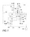
原子層蒸着(「ALD」)は、好ましくは、パージ中に蒸着チャンバを通過する可能な限り最高の流量で、且つ、化学物質の投与中に可能な限り最低の流量で実施される。したがって、本発明によるALDシステムは、ALDサイクル中に、流量の顕著な変調を生じさせ吸収する。プロセスチャンバ(又はALDチャンバもしくは蒸着チャンバ)へのプロセスガス(不活性パージガス又は化学反応物質ガスのいずれか)の流れを本明細書において「フロー」と称し、プロセスチャンバから出るガスの流れを本明細書において「ドロー」と称する。定常状態条件下で、ドローは、一般にフローと一致する。過渡的流れ条件中、フロー及びドローは「不一致」である。 Atomic layer deposition (“ALD”) is preferably performed at the highest possible flow rate through the deposition chamber during purging and at the lowest possible flow rate during chemical administration. Thus, the ALD system according to the present invention causes and absorbs significant modulation of flow during the ALD cycle. The flow of process gas (either inert purge gas or chemical reactant gas) to the process chamber (or ALD chamber or deposition chamber) is referred to herein as “flow” and the flow of gas exiting the process chamber is described herein. This is referred to as “draw”. Under steady state conditions, the draw is generally consistent with the flow. During transient flow conditions, the flow and draw are “mismatched”.
本発明による実施形態の重要な側面は、蒸着チャンバのパージ中には大きな流量を必要とし、化学物質投与中には小さな流量を必要とする2種の相反する要求の間で、慣用のALDシステムの兼ね合いを解決することである。本発明によるSMFDは、低圧及び高いパージガス流量にてプロセスチャンバをパージし、続いてプロセスチャンバ内で化学反応物質ガスの高圧及び低い流量での化学物質投与を行い、早い応答時間で圧力及びガス流量を緩和する能力を与える。 An important aspect of embodiments according to the present invention is that a conventional ALD system is used between two conflicting demands that require a high flow rate during deposition chamber purge and a low flow rate during chemical dosing. It is to solve the trade-off. The SMFD according to the present invention purges the process chamber at a low pressure and a high purge gas flow rate, followed by high pressure and low flow rate chemical reaction of the chemical reactant gas in the process chamber, with a fast response time pressure and gas flow rate. Give the ability to relax.
一側面において、本発明による方法は、第1の化学反応物質ガスを選択された第1の投与流量にて且つ独立に選択された第1の投与圧力にて、蒸着チャンバを貫通して流す第1の化学物質投与ステージを行い、;第二に、第1のパージガスを選択された第1のパージ流量にて且つ独立に選択された第1のパージ圧力にて、蒸着チャンバを貫通して流すことにより第1のパージステージを行い;第三に、第2の化学反応物質ガスを選択された第2の投与流量にて且つ独立に選択された第2の投与圧力にて、蒸着チャンバを貫通して流すことを含む第2の化学物質投与ステージを行い;第四に、第2のパージガスを選択された第2のパージ流量にて且つ独立に選択された第2のパージ圧力にて、蒸着チャンバを貫通して流すことにより第2のパージステージを行う、サイクルを含む。典型的には、第1のパージガス及び第2のパージガスは同じであり、共通のパージガス源により供給される。本発明による方法の固有の特徴は、第1の化学物質投与ステージ、第1のパージステージ、第2の投与ステージ、及び第2のパージステージが、それぞれ、選択され制御された時間で行われ、サイクルの各繰り返しにおいて同じものが残ることである。典型的な4ステージサイクルは、通常、ALDプロセスにおける単一の薄膜を堆積するために、多数回又は数百回、繰り返される。本発明による実施形態の重要な利点は、サイクルの各ステージの持続時間であり、よってサイクルの総持続時間が典型的には慣用のALDプロセス及びシステムにて実際に実現可能な時間よりも非常に短いことである。ゆえに、第1の化学物質投与ステージ、第1のパージステージ、第2の化学物質投与ステージ、第2のパージステージを逐次的に行うことは、典型的には、3秒未満でシーケンスを行うこと、好ましくは1秒未満で、より好ましくは0.5秒未満でシーケンスを行うことを含む。例えば、Al2O3の優れたALD薄膜は、サイクル時間がわずかに450ミリ秒(「msec」)である本発明による方法によって製造される。良好な薄膜品質を維持しながら処理量を最大化するために、各4ステージの持続時間は、典型的には他のステージとは異なる。さらに、各ステージの流量は、典型的には、サイクルにおける他のステージの流量とは異なる。一般に、第1のパージ流量は第1の投与流量よりも大きく、第1のパージ流量の第1の投与流量に対する比率は、典型的には1.5を超え、通常は20を超え、好ましくは100を超える。同様に、第2のパージ流量は一般に、第2の投与流量よりも大きく、第2の投与流量に対する第2のパージ流量の比率は、典型的には1.5を超え、通常は20を超え、好ましくは100を超える。In one aspect, a method according to the present invention includes a first chemical reactant gas flowing through a deposition chamber at a selected first dosage flow rate and at an independently selected first dosage pressure. One chemical administration stage; and second, a first purge gas is flowed through the deposition chamber at a selected first purge flow rate and at an independently selected first purge pressure. A first purge stage; and third, a second chemical reactant gas is passed through the deposition chamber at a selected second dose flow rate and at an independently selected second dose pressure. Performing a second chemical dosing stage including flowing; and fourth, depositing a second purge gas at a selected second purge flow rate and at an independently selected second purge pressure. A second part by flowing through the chamber. Do the stage, including the cycle. Typically, the first purge gas and the second purge gas are the same and are supplied by a common purge gas source. A unique feature of the method according to the invention is that the first chemical administration stage, the first purge stage, the second administration stage, and the second purge stage are each performed at a selected and controlled time, The same remains at each iteration of the cycle. A typical four stage cycle is typically repeated many or hundreds of times to deposit a single thin film in an ALD process. An important advantage of embodiments according to the present invention is the duration of each stage of the cycle, so the total duration of the cycle is typically much greater than what is actually achievable with conventional ALD processes and systems. It is short. Therefore, sequentially performing the first chemical substance administration stage, the first purge stage, the second chemical substance administration stage, and the second purge stage is typically performed in less than 3 seconds. , Preferably in less than 1 second, more preferably in less than 0.5 seconds. For example, an excellent ALD thin film of Al2 O3 is produced by the method according to the invention with a cycle time of only 450 milliseconds (“msec”). In order to maximize throughput while maintaining good thin film quality, the duration of each of the four stages is typically different from the other stages. Furthermore, the flow rate of each stage is typically different from the flow rates of the other stages in the cycle. In general, the first purge flow rate is greater than the first dose flow rate and the ratio of the first purge flow rate to the first dose flow rate is typically greater than 1.5, usually greater than 20, preferably Over 100. Similarly, the second purge flow rate is generally greater than the second dose flow rate, and the ratio of the second purge flow rate to the second dose flow rate is typically greater than 1.5 and typically greater than 20. , Preferably over 100.
別の側面において、第1の化学物質投与ステージを開始することは、第1の化学反応物質ガスを第1の過渡的流量にて最初に流すことを含み、第1の過渡的流量は第1の投与流量よりも最初は実質的に大きい。また別の側面において、第2の化学物質投与ステージを開始することは、第2の化学反応物質ガスを第2の過渡的流量にて最初に流すことを含み、第2の過渡的流量は第2の投与流量よりも最初は実質的に大きい。 In another aspect, initiating the first chemical dosing stage includes first flowing a first chemical reactant gas at a first transient flow rate, the first transient flow rate being a first transient flow rate. Initially substantially greater than the dosing flow rate. In yet another aspect, initiating the second chemical dosing stage includes first flowing a second chemical reactant gas at a second transient flow rate, wherein the second transient flow rate is the second transient flow rate. Initially substantially greater than 2 dose flow.
別の側面において、第1の化学反応物質ガスを選択された第1の投与流量にて且つ独立に選択された第1の投与圧力にて流すことは、蒸着チャンバへの第1の化学反応物質ガスの第1の投与流量を制御し、独立に、蒸着チャンバから出る第1の化学反応物質ガスの第1の化学物質ドローを第1の投与流量と実質的に一致させることを含む。別の側面において、蒸着チャンバから出る第1の化学反応物質ガスの第1の化学物質ドローを独立に実質的に一致させることは、蒸着チャンバから下流の第1の投与ドロー圧力を制御することを含む。別の側面において、第1の投与ドロー圧力を制御することは、ドロー制御チャンバを貫通して第1の投与ドローガス流量にてドローガスを流すこと、及び第1の投与ドローガス流量を制御して第1の投与ドロー圧力を達成することを含み、ドロー制御チャンバは蒸着チャンバから下流に位置づけられている。 In another aspect, flowing a first chemical reactant gas at a selected first dosage flow rate and at an independently selected first dosage pressure provides a first chemical reactant to the deposition chamber. Controlling the first dose flow of the gas and independently including substantially matching the first chemical draw of the first chemical reactant gas exiting the deposition chamber with the first dose flow. In another aspect, independently and substantially matching the first chemical draw of the first chemical reactant gas exiting the deposition chamber independently controls the first dose draw pressure downstream from the deposition chamber. Including. In another aspect, controlling the first dose draw pressure includes flowing a draw gas at a first dose draw gas flow rate through the draw control chamber and controlling the first dose draw gas flow rate to the first. A draw control chamber is positioned downstream from the deposition chamber.
別の側面において、選択された第1のパージ流量にて且つ独立に選択された第1のパージガス圧力にて蒸着チャンバを貫通して第1のパージガスを流すことは、蒸着チャンバへの第1のパージガスの第1のパージ流量を制御すること、蒸着チャンバを出る第1のパージガスの第1のパージドローを第1のパージ流量に独立に実質的に一致させること、を含む。別の側面において、蒸着チャンバを出る第1のパージガスの第1のパージドローを独立に実質的に一致させることは、蒸着チャンバから下流の第1のパージドロー圧力を制御することを含む。別の側面において、第1のパージドロー圧力を制御することは、ドロー制御チャンバを貫通して、第1のパージドローガス流量にてドローガスを流すこと、及び第1のパージドロー流量を制御して第1のパージドロー圧力を達成すること、を含む。 In another aspect, flowing the first purge gas through the deposition chamber at a selected first purge flow rate and at an independently selected first purge gas pressure is the first to the deposition chamber. Controlling a first purge flow rate of the purge gas and independently matching substantially the first purge draw of the first purge gas exiting the deposition chamber to the first purge flow rate. In another aspect, independently substantially matching the first purge draw of the first purge gas exiting the deposition chamber includes controlling a first purge draw pressure downstream from the deposition chamber. In another aspect, controlling the first purge draw pressure includes passing a draw gas through the draw control chamber at a first purge draw gas flow rate and controlling the first purge draw flow rate to a first Achieving a purge draw pressure of.
別の側面において、第2の化学反応物質ガスを選択された第2の投与流量にて且つ独立に選択された第2の投与圧力にて流すことは、蒸着チャンバへの第2の化学反応物質ガスの第2の投与流量を制御して、蒸着チャンバを出る第2の化学反応物質ガスの第2の化学物質ドローを第2の投与流量に独立に実質的に一致させることを含む。別の側面において、蒸着チャンバを出る第2の化学反応物質ガスの第2の化学物質ドローを独立に実質的に一致させることは、蒸着チャンバから下流の第2の投与ドロー圧力を制御することを含む。別の側面において、第2の投与ドロー圧力を制御することは、ドローガスを第2の投与ドローガス流量にてドロー制御チャンバを貫通して流すこと、及び第2の投与ドローガス流量を制御して第2の投与ドロー圧力を達成すること、を含む。 In another aspect, flowing a second chemical reactant gas at a selected second dosage flow rate and at an independently selected second dosage pressure provides a second chemical reactant to the deposition chamber. Controlling the second dosage flow rate of the gas to independently substantially match the second chemical draw of the second chemical reactant gas exiting the deposition chamber to the second dosage flow rate. In another aspect, independently substantially matching the second chemical draw of the second chemical reactant gas exiting the deposition chamber controls the second dosing draw pressure downstream from the deposition chamber. Including. In another aspect, controlling the second dose draw pressure includes flowing a draw gas through the draw control chamber at a second dose draw gas flow rate and controlling the second dose draw gas flow rate to a second. Achieving a dosing draw pressure of.
別の側面において、第2のパージガスを選択された第2のパージ流量にて且つ独立に選択された第2のパージ圧力にて蒸着チャンバを貫通して流すことは、蒸着チャンバへの第2のパージガスの第2のパージ流量を制御すること、及び蒸着チャンバを出る第2のパージガスの第2のパージドローを第2のパージ流量に独立に実質的に一致させること、を含む。別の側面において、蒸着チャンバを出る第2のパージガスの第2のパージドローを独立に実質的に一致させることは、蒸着チャンバから下流の第2のパージドロー圧力を制御することを含む。別の側面において、第2のパージドロー圧力を制御することは、ドローガスを第2のパージドロー流量にてドロー制御チャンバを貫通して流すこと、第2のパージドローガス流量を制御して第2のパージドロー圧力を達成すること、を含み、ドロー制御チャンバは蒸着チャンバから下流に位置づけられている。 In another aspect, flowing a second purge gas through the deposition chamber at a selected second purge flow rate and at an independently selected second purge pressure is a second to the deposition chamber. Controlling a second purge flow rate of the purge gas, and independently substantially matching a second purge draw of the second purge gas exiting the deposition chamber to the second purge flow rate. In another aspect, independently substantially matching the second purge draw of the second purge gas exiting the deposition chamber includes controlling a second purge draw pressure downstream from the deposition chamber. In another aspect, controlling the second purge draw pressure includes flowing a draw gas through the draw control chamber at a second purge draw flow rate, controlling the second purge draw gas flow rate to control the second purge draw flow. Achieving a pressure, and the draw control chamber is positioned downstream from the deposition chamber.
別の側面において、第1の化学反応物質ガスを選択された第1の投与流量にて且つ独立に選択された第1の投与圧力にて流すことは、蒸着チャンバへの第1の化学反応物質ガスの第1の投与流量を制御すること、蒸着チャンバから下流のドロー圧力を制御することによって蒸着チャンバから出る第1の化学反応物質ガスの第1の投与流量と第1の化学物質ドローとの間の不一致を独立に実質的に発生させることを含み、圧力移行期間中、蒸着チャンバ内の第1の投与圧力が実質的に変動し、こうして第1の化学物質ドローを第1の投与流量に実質的に一致させる。 In another aspect, flowing a first chemical reactant gas at a selected first dosage flow rate and at an independently selected first dosage pressure provides a first chemical reactant to the deposition chamber. Controlling a first dosage flow rate of the gas, a first dosage flow rate of the first chemical reactant gas exiting the deposition chamber by controlling a draw pressure downstream from the deposition chamber, and a first chemical draw The first dosing pressure in the deposition chamber is substantially varied during the pressure transition period, thus causing the first chemical draw to the first dosing flow rate. Substantially match.
別の側面において、第2の化学反応物質ガスを選択された第2の投与流量にて且つ独立に選択された第2の投与圧力にて流すことは、蒸着チャンバへの第2の化学反応物質ガスの第2の投与流量を制御すること、及び蒸着チャンバから下流のドロー圧力を制御することによって第2の投与流量と、蒸着チャンバから出る第2の化学反応物質ガスの第2の化学物質ドローとの間に不一致を独立に意図的に発生させること、圧力移行期間中、蒸着チャンバ内での第2の投与圧力が実質的に変動して実質的に不一致を減少させ、こうして第2の化学物質ドローを第2の投与流量に実質的に一致させること、を含む。 In another aspect, flowing a second chemical reactant gas at a selected second dosage flow rate and at an independently selected second dosage pressure provides a second chemical reactant to the deposition chamber. Controlling the second dose flow of the gas and controlling the draw pressure downstream from the deposition chamber and the second chemical draw of the second chemical reactant gas exiting the deposition chamber; Inconsistently and independently, and during the pressure transition, the second dosing pressure in the deposition chamber is substantially varied to substantially reduce the inconsistency, and thus the second chemistry. Substantially matching the substance draw to the second dosage flow rate.
別の側面において、第1の化学反応物質ガスを蒸着チャンバに流通させることは、既知の第1源圧力を有する第1の反応物質ガス源を提供することと、第1の化学物質ガスを第1の反応物質ガス源から第1の源流量制限要素(FRE)を通して蒸着チャンバに流すことと、を含む。 In another aspect, flowing the first chemical reactant gas to the deposition chamber provides a first reactant gas source having a known first source pressure; and Flowing from one reactant gas source through a first source flow restriction element (FRE) to the deposition chamber.
別の側面において、第2の化学反応物質ガスを蒸着チャンバに流通させることは、既知の第2源圧力を有する第2の反応物質ガス源を提供することと、第2の化学反応物質ガスを第2の反応物質ガス源から第2の源FREを通して蒸着チャンバに流すことと、を含む。 In another aspect, flowing the second chemical reactant gas to the deposition chamber provides a second reactant gas source having a known second source pressure; and Flowing from the second reactant gas source through the second source FRE to the deposition chamber.
さらに別の側面において、本発明による方法は、好ましくは、第1の源FREから下流側で且つ蒸着チャンバから上流側に位置づけられている第1のブースターチャンバを、第1の化学物質投与ステージを含まない期間中に、実質的に既知の第1源圧力における第1の化学反応物質ガスで充填することと、続いて、第1のブースターチャンバと蒸着チャンバとの間で連続流体連通状態にある第1の化学物質遮断弁を開いて第1の化学物質投与ステージを開始することとをさらに含み、こうして第1の化学反応物質ガスを、第1の投与流量よりも最初は実質的に大きな第1の過渡的流量にて最初に流す。 In yet another aspect, the method according to the present invention preferably comprises a first booster chamber positioned downstream from the first source FRE and upstream from the deposition chamber, the first chemical dosing stage. During a free period, filling with a first chemical reactant gas at a substantially known first source pressure, followed by continuous fluid communication between the first booster chamber and the deposition chamber. Opening a first chemical shut-off valve and initiating a first chemical dosing stage, thus causing the first chemical reactant gas to flow through the first substantially larger first flow rate than the first dosing flow rate. First flow at a transient flow rate of 1.
さらにまた別の側面において、本発明による方法は、好ましくは、第2の源FREから下流側で且つ蒸着チャンバから上流側に位置づけられている第2のブースターチャンバを、第2の化学物質投与ステージを含まない期間中に、実質的に既知の第2源圧力における第2の化学反応物質ガスで充填することと、続いて、第2のブースターチャンバと蒸着チャンバとの間で連続流体連通状態にある第2の化学物質遮断弁を開いて第2の化学物質投与ステージを開始することとをさらに含み、こうして第2の化学反応物質ガスを、第2の投与流量よりも最初は実質的に大きい第2の過渡的流量にて最初に流す。 In yet another aspect, the method according to the present invention preferably comprises a second booster chamber positioned downstream from the second source FRE and upstream from the deposition chamber, the second chemical dosing stage. Charging with a second chemical reactant gas at a substantially known second source pressure during a period that does not include a gas, followed by continuous fluid communication between the second booster chamber and the deposition chamber. Opening a second chemical shut-off valve to initiate a second chemical dosing stage, thus causing the second chemical reactant gas to be initially substantially greater than the second dosing flow rate. Flow first with a second transient flow rate.
一側面において、本発明による装置は、プロセスチャンバ内のガスのフロー、ドロー及び圧力を同期的に調整することができる。ここで、用語「同期的に」とは、早い応答時間で、ガス流量の圧力の未制御の変位を最小にして、素早い制御された連続状態を意味する。本発明によるシステムは、プロセスチャンバ(PC)へのガスの流れを調整することができ、PC内のガスの流れ及び滞留時間を実質的に調整しながら、蒸着全体にわたって実質的に定常圧力を維持するため、プロセスチャンバから出るガスのドローと、フローとを、実質的に同時に且つ独立に一致させることができる装置である。大きな流れ調整に対応することは、パージステージ及び投与ステージの独自の最適化を可能とし、SMFD実装の重要な利点である。それにもかかわらず、いくつかの実施形態において、いくらかの制限された意図的な圧力調整、特に化学物質投与中の所望の圧力増加が、流れ調整に加えて、実施される。このような圧力調整は、フロー調整と同時のドロー調整がある種の所定の不一致を伴う場合に、達成される。この不一致は、申し分なく設計されたSMFD装置及び方法に逆流を発生させないものであるが、圧力移行期間中に、PC内の圧力に変化を生じさせてフローとドローとの一致に到達させ、こうして同期圧力調整を効果的にする。 In one aspect, the apparatus according to the present invention can synchronously adjust the gas flow, draw and pressure in the process chamber. Here, the term “synchronously” means a fast controlled continuous state with fast response time and minimal uncontrolled displacement of gas flow pressure. The system according to the present invention can regulate the flow of gas into the process chamber (PC) and maintain a substantially steady pressure throughout the deposition while substantially adjusting the flow of gas and residence time in the PC. Thus, the apparatus can match the draw of gas exiting the process chamber and the flow substantially simultaneously and independently. Accommodating large flow adjustments is a key advantage of SMFD implementations, allowing for unique optimization of the purge and dosing stages. Nevertheless, in some embodiments, some limited intentional pressure adjustment, particularly the desired pressure increase during chemical administration, is performed in addition to the flow adjustment. Such pressure adjustment is achieved when there is a certain predetermined discrepancy with the draw adjustment coincident with the flow adjustment. This discrepancy does not cause backflow in a well-designed SMFD device and method, but during the pressure transition period, it causes a change in the pressure in the PC to reach a match between flow and draw, thus Synchronous pressure adjustment is effective.
別の側面において、装置は、プロセスチャンバと、プロセスチャンバへのガスの流量を制御するためのプロセスチャンバに接続されているプロセスガス導管と、ドローガスフロー用に構成されているドロー制御チャンバ(DC)と、プロセスチャンバとドロー制御チャンバとの間で連続流体連通状態にあるプロセスチャンバ流量制限要素(FRE)と、ドロー制御チャンバと連続流体連通状態にあるドロー排気ラインと、ドロー排気ラインと連続流体連通状態にあるドロー制御FREと、を含む。一般に、FREは、ガス流路にある種のコンダクタンス(または逆に抵抗)を与えるように設計されている。別の側面において、システムは、さらに、ドロー制御チャンバを通るドローガスの流れを制御するためのドロー源遮断弁を含む。また別の側面において、システムは、ドロー遮断弁及びドロー制御チャンバと連続流体連通状態にあるドロー源FREを含む。別の側面において、システムは、プロセスガス導管と連続流体連通状態にある複数のプロセスガス遮断弁をさらに含む。各遮断弁は、プロセスチャンバへのプロセスガスの流入を制御するように構成されている。別の側面において、プロセスガス遮断弁の一つは、プロセスチャンバと連続流体連通状態にあるプロセスチャンバへのパージガスの流れを制御するための1個のパージ源遮断弁を含む。別の側面において、システムは、パージ源遮断弁と連続流体連通状態にある1個のパージ源FREをさらに含む。別の側面において、システムは、複数のプロセスガスFREをさらに含み、各プロセスガスFREはプロセスガス遮断弁の一つと連続流体連通状態にある。別の側面において、システムは、複数のブースターチャンバをさらに含み、各ブースターチャンバはプロセスガス導管と連続流体連通状態にあり、各ブースターチャンバはプロセスガス遮断弁の一つから上流側に且つプロセスガスFREの一つから下流側に位置している。別の側面において、システムは、複数のブースターFREをさらに含み、各ブースターFREはブースターチャンバの一つから下流側にある。別の側面において、システムは、プロセスガス遮断弁とプロセスチャンバとの間で連続流体連通状態にあり且つパージ源遮断弁とプロセスチャンバとの間で連続流体連通状態にある1個のガス分配チャンバと、ガス分配チャンバとプロセスチャンバとの間で連続流体連通状態にある1個のガス分配FREとをさらに含む。また別の側面において、ガス分配FREは、ノズル列を含む。別の側面において、ノズル列は、1.5以上のアスペクト比を有する複数のノズルを含む。 In another aspect, an apparatus includes a process chamber, a process gas conduit connected to the process chamber for controlling the flow rate of gas to the process chamber, and a draw control chamber (DC) configured for draw gas flow. ), A process chamber flow restriction element (FRE) in continuous fluid communication between the process chamber and the draw control chamber, a draw exhaust line in continuous fluid communication with the draw control chamber, a draw exhaust line and continuous fluid And a draw control FRE in the communication state. In general, FREs are designed to provide some sort of conductance (or conversely resistance) in the gas flow path. In another aspect, the system further includes a draw source shut-off valve for controlling the flow of draw gas through the draw control chamber. In yet another aspect, the system includes a draw source FRE in continuous fluid communication with a draw shut-off valve and a draw control chamber. In another aspect, the system further includes a plurality of process gas shut-off valves in continuous fluid communication with the process gas conduit. Each shut-off valve is configured to control the flow of process gas into the process chamber. In another aspect, one of the process gas shut-off valves includes a single purge source shut-off valve for controlling the flow of purge gas to the process chamber in continuous fluid communication with the process chamber. In another aspect, the system further includes a single purge source FRE in continuous fluid communication with the purge source shut-off valve. In another aspect, the system further includes a plurality of process gas FREs, each process gas FRE being in continuous fluid communication with one of the process gas shut-off valves. In another aspect, the system further includes a plurality of booster chambers, wherein each booster chamber is in continuous fluid communication with the process gas conduit, each booster chamber being upstream from one of the process gas isolation valves and the process gas FRE. It is located downstream from one of these. In another aspect, the system further includes a plurality of booster FREs, each booster FRE being downstream from one of the booster chambers. In another aspect, the system includes a gas distribution chamber in continuous fluid communication between the process gas shutoff valve and the process chamber and in continuous fluid communication between the purge source shutoff valve and the process chamber; And a single gas distribution FRE in continuous fluid communication between the gas distribution chamber and the process chamber. In another aspect, the gas distribution FRE includes a nozzle row. In another aspect, the nozzle row includes a plurality of nozzles having an aspect ratio of 1.5 or greater.
別の側面において、システムは、ガス分配チャンバと連続流体連通状態にあるパージ排気ラインと、ガス分配チャンバとパージ排気ラインとの間で連続流体連通状態にあるパージ排気遮断弁と、をさらに含む。別の側面において、システムは、パージ排気遮断弁と連続流体連通状態にあるパージ排気FREをさらに含む。別の側面において、いくつかのプロセスガス遮断弁は、複数の非共通ポートと複数の共通ポートとを有する多方向バルブを含み、各非共通ポートはプロセスガス源と連続流体連通状態にあり、複数の共通ポートはプロセスチャンバと連続流体連通状態にあり、少なくとも1個の共通ポートはパージ源遮断弁と連続流体連通状態にある。 In another aspect, the system further includes a purge exhaust line in continuous fluid communication with the gas distribution chamber and a purge exhaust shut-off valve in continuous fluid communication between the gas distribution chamber and the purge exhaust line. In another aspect, the system further includes a purge exhaust FRE in continuous fluid communication with the purge exhaust shut-off valve. In another aspect, some process gas shut-off valves include multi-directional valves having a plurality of non-common ports and a plurality of common ports, each non-common port being in continuous fluid communication with the process gas source, The common port is in continuous fluid communication with the process chamber and at least one common port is in continuous fluid communication with the purge source shutoff valve.
いくつかの好ましい実施形態において、装置は、プロセスチャンバとドロー制御チャンバとの間で連続流体連通状態にあるドローガス導入チャンバ(DGIC)と、DGICへのドローガスの流れを制御するドロー源遮断弁と、プロセスチャンバとDGICとの間に位置づけられているプロセスチャンバFREと、DGICとドロー制御チャンバとの間に位置づけられているDGIC-FREと、をさらに含む。別の側面において、システムは、ドロー源遮断弁とDGICとの間で連続流体連通状態に位置づけられているドロー源−FREをさらに含む。 In some preferred embodiments, the apparatus includes a draw gas introduction chamber (DGIC) in continuous fluid communication between the process chamber and a draw control chamber, a draw source shut-off valve that controls the flow of draw gas to the DGIC, Further included is a process chamber FRE positioned between the process chamber and the DGIC, and a DGIC-FRE positioned between the DGIC and the draw control chamber. In another aspect, the system further includes a draw source-FRE positioned in continuous fluid communication between the draw source shut-off valve and the DGIC.
別の側面において、システムは、ドロー制御チャンバ内に位置づけられている排除表面(abatement surface)をさらに含む。また別の側面において、システムは、化学物質排除を増強させるため、反応性ガスをドロー制御チャンバ内に導入するための反応性ガス入口をさらに含む。別の側面において、反応性ガス入口は、ドロー制御チャンバに近接する反応性ガスプレナムを含む。別の側面において、システムは、ドロー制御チャンバから下流側に位置づけられている排除チャンバをさらに含む。 In another aspect, the system further includes an abatement surface positioned within the draw control chamber. In yet another aspect, the system further includes a reactive gas inlet for introducing reactive gas into the draw control chamber to enhance chemical exclusion. In another aspect, the reactive gas inlet includes a reactive gas plenum adjacent to the draw control chamber. In another aspect, the system further includes an exclusion chamber positioned downstream from the draw control chamber.
別の側面において、システムは、ドロー制御チャンバから下流側に位置づけられており且つドロー制御チャンバ及びドロー排気ラインと連続流体連通状態にある圧力制御チャンバをさらに含む。別の側面において、プロセスチャンバは、原子層蒸着チャンバ(ALDC)である。 In another aspect, the system further includes a pressure control chamber positioned downstream from the draw control chamber and in continuous fluid communication with the draw control chamber and the draw exhaust line. In another aspect, the process chamber is an atomic layer deposition chamber (ALDC).
別の側面において、本発明によるシステムは、反応容器壁と容器内部とを有し、容器内部に蒸着チャンバと、DGICと、ドロー制御チャンバとが囲包されている反応容器を含む。
別の側面において、本発明によるシステムは、周囲スロットバルブ(PSV)を包含する反応容器を含む。周囲スロットバルブは、反応容器壁を貫通する基板搬送スロットと、反応容器壁内の連続周囲空隙と、連続周囲シーリングポペット弁と、シーリングポペット弁を開位置と閉位置との間で移動させるためのアクチュエータと、を含む。シーリングポペット弁は、閉位置にあるときに周囲空隙内に移動し、開位置にあるときに周囲空隙から出るように移動する。基板搬送スロットは、基板ホルダーの基板支持表面と実質的に面一であり、周囲空隙は基板搬送スロットと実質的に面一である。シーリングポペット弁が開位置にあるとき、基板搬送スロットは、反応容器壁を基板ホルダーまで貫通する基板搬送チャネルを画定する。シーリングポペット弁が閉位置にあるとき、シーリングポペット弁は基板搬送スロットを容器内部から分離する。In another aspect, a system according to the present invention includes a reaction vessel having a reaction vessel wall and a vessel interior, in which a deposition chamber, a DGIC, and a draw control chamber are enclosed.
In another aspect, a system according to the present invention includes a reaction vessel that includes a peripheral slot valve (PSV). The peripheral slot valve is used to move the substrate transfer slot through the reaction vessel wall, the continuous peripheral gap in the reaction vessel wall, the continuous peripheral sealing poppet valve, and the sealing poppet valve between the open position and the closed position. An actuator. The sealing poppet valve moves into the surrounding gap when in the closed position and exits from the surrounding gap when in the open position. The substrate transfer slot is substantially flush with the substrate support surface of the substrate holder, and the peripheral gap is substantially flush with the substrate transfer slot. When the sealing poppet valve is in the open position, the substrate transfer slot defines a substrate transfer channel that extends through the reaction vessel wall to the substrate holder. When the sealing poppet valve is in the closed position, the sealing poppet valve separates the substrate transfer slot from the interior of the container.
いくつかの実施形態において、プロセスチャンバ(又はALDチャンバ)内の圧力は、同期フロー−ドロー調整中、実質的に一定に維持される。本発明による他の実施形態において、処理量及び物質利用率は、高圧にて、1以上の化学物質投与ステージを行うことにより、さらに改良される。例えば、いくつかの実施形態において、パージ中の圧力は、約30mTorr〜100mTorrの範囲に維持され、化学物質投与中のALD圧力は約200mTorr〜1000mTorrの範囲に維持される。 In some embodiments, the pressure in the process chamber (or ALD chamber) is maintained substantially constant during synchronous flow-draw adjustment. In other embodiments according to the invention, throughput and substance utilization are further improved by performing one or more chemical dosing stages at high pressure. For example, in some embodiments, the pressure during purging is maintained in the range of about 30 mTorr to 100 mTorr, and the ALD pressure during chemical administration is maintained in the range of about 200 mTorr to 1000 mTorr.
別の側面において、本発明による実施形態は、プロセスチャンバへプロセスガスを流すことにより、また、プロセスチャンバと流体連通状態にありプロセスチャンバから下流側にあるドロー制御チャンバへドロー制御ガスを流すことにより、プロセスチャンバ内の圧力を制御し、こうして、プロセスチャンバから下流側のドロー圧力を制御する。別の側面において、ドロー制御チャンバへドロー制御ガスを流入させることは、ドロー制御チャンバ内化学物質排除を促進するために反応性ガスを流すことを含む。別の側面において、ドロー圧力は、1atm未満に、典型的には5Torr未満に、制御される。 In another aspect, embodiments according to the present invention provide a process gas flow to the process chamber and a flow of the draw control gas to a draw control chamber in fluid communication with the process chamber and downstream from the process chamber. Control the pressure in the process chamber and thus the draw pressure downstream from the process chamber. In another aspect, flowing the draw control gas into the draw control chamber includes flowing a reactive gas to facilitate chemical exclusion within the draw control chamber. In another aspect, the draw pressure is controlled to be less than 1 atm, typically less than 5 Torr.
[好ましい実施形態の詳細な説明]
図面を参照することにより、本発明をより完全に理解できるであろう。
図1〜17を参照しながら、本発明を説明する。明確にするために、いくつかの図面において、類似又は同一の成分に対しては同じ参照符号を用いる。図1〜17に概略的に示されている構造及びシステムは例示であり、本発明による実際の構造及びシステムの正確な図示ではないことは理解されるべきである。さらに、本明細書に記載された実施形態は、例示であり、特許請求の範囲に規定されている本発明の範囲を限定するものではない。以下、本発明による実施形態を、単一の200mmウェハ基板上のALD蒸着のためのシステム及び方法を主として参照しながら記載する。本発明は、より大規模又はより小規模でも有用であり、以下に記載する寸法及び運転変数は適宜スケールアップしたりスケールダウンしたりすることができることは理解されよう。Detailed Description of Preferred Embodiments
The invention can be more fully understood with reference to the drawings.
The present invention will be described with reference to FIGS. For clarity, the same reference numbers are used for similar or identical components in the several figures. It should be understood that the structures and systems schematically shown in FIGS. 1-17 are exemplary and not an accurate representation of the actual structures and systems according to the present invention. Furthermore, the embodiments described herein are illustrative and do not limit the scope of the invention as defined in the claims. In the following, embodiments according to the present invention will be described with primary reference to systems and methods for ALD deposition on a single 200 mm wafer substrate. It will be appreciated that the present invention is useful on a larger or smaller scale, and that the dimensions and operating variables described below can be scaled up or down as appropriate.
原子層蒸着(ALD)は、好ましくは、パージ中に蒸着チャンバを通過する可能な限り最高の流量で実施され、化学物質投与中に可能な限り最低の流量で実施される。したがって、効果的なALDシステムは、流量の大幅な調整を生じさせ且つ吸収することができる。定常状態条件下にて、チャンバ内へのプロセスガス(不活性パージガス又は化学反応物質ガスのいずれか)の流れ(本明細書にて「フロー」という)は、チャンバから出るガスの流れ(本明細書にて「ドロー」という)と一致する。 Atomic layer deposition (ALD) is preferably performed at the highest possible flow rate through the deposition chamber during purging and at the lowest possible flow rate during chemical administration. Thus, an effective ALD system can cause and absorb significant adjustments in flow rate. Under steady state conditions, the flow of process gas (either inert purge gas or chemical reactant gas) into the chamber (referred to herein as “flow”) is the flow of gas out of the chamber (referred to herein). Matches the word “draw”.
大幅な流れ調整を吸収するために、本発明によるシステムは、フローとドローとを実質的に一致させることができる。たとえば、代表的なALDサイクルは、それぞれ、10sccm、1000sccm、5sccm、及び1000sccmのガス流量での化学物質A投与、化学物質Aパージ、化学物質B投与、化学物質Bパージのシーケンスを含む。実質的に同じ流量にて同期的に調整するためにドローが制御される場合には、プロセス圧力は、実質的に定常に維持される。 In order to absorb significant flow regulation, the system according to the present invention can substantially match the flow and draw. For example, a typical ALD cycle includes a chemical A dose, a chemical A purge, a chemical B dose, and a chemical B purge sequence at gas flow rates of 10 sccm, 1000 sccm, 5 sccm, and 1000 sccm, respectively. If the draw is controlled to adjust synchronously at substantially the same flow rate, the process pressure is maintained substantially steady.
ドローの調整がフロー調整と実質的に一致しない場合には、システムはプロセス圧力を維持しない。代わりに、システムは、フロー及びドローを一致させる実質的に異なる圧力に不可避的に遷移する。 If the draw adjustment does not substantially match the flow adjustment, the system does not maintain the process pressure. Instead, the system inevitably transitions to substantially different pressures that match the flow and draw.
蒸着チャンバ又は他のタイプのプロセスチャンバへのフローは、一般に、プロセス圧力とは実質的に独立に、アップストリームマニホルドを用いて制御される。ドローは、一般に、プロセスチャンバ出口のコンダクタンスCPCにより、及び出口を横断する差圧ΔP=PPC−PDRAWによって決定される。したがって、ドロー=CPCΔP。一般に、ドロー調整は、コンダクタンスCPC又は差圧ΔPの一方又は双方を調整することによって達成され得る。プロセスチャンバから出るコンダクタンスを調整することは、一般に、スロットルバルブと名付けられた機械的装置を用いて、CVD、PVD及びエッチングシステムなどのプロセスフローシステムの分野で用いられている。スロットルバルブは、これらのシステムにおいて定常状態圧力を制御するために適切に用いられているが、これらは、現在、SMFDシステムに必要とされる早い応答時間に適応するには、ゆっくりすぎる。加えて、スロットルバルブは、望ましくない流れの乱れを引き起こし、粒子を発生させる。流れひずみ及び粒子発生問題を回避するために、スロットルバルブは、典型的には、プロセスゾーンから大きく離れている下流側位置で、従来利用されている。しかし、好ましいALDシステム設計は、ALD蒸着チャンバ容積を最小化し、ドロー制御の位置を基板に近づける。プロセス出口の温度を変化させるなど、コンダクタンスを調整する他の手段は、範囲がより限定され非常に遅い。最後に、ドロー調整は、真空ポンプのポンプ排気速度を調整することにより、達成され得る。しかし、大きなポンプ排気速度調整は、ゆっくりと応答し、所望のALDスイッチング速度にて試行される際に、さらにポンプを大きく摩耗させる。The flow to the deposition chamber or other type of process chamber is generally controlled using an upstream manifold, substantially independent of the process pressure. The draw is generally determined by the conductance CPC at the process chamber outlet and by the differential pressure ΔP = PPC −PDRAW across the outlet. Therefore, draw = CPC ΔP. In general, the draw adjustment can be achieved by adjusting one or both of the conductance CPC or differential pressure [Delta] P. Adjusting the conductance exiting the process chamber is commonly used in the field of process flow systems such as CVD, PVD, and etching systems, using a mechanical device named a throttle valve. Although throttle valves are properly used to control steady state pressure in these systems, they are currently too slow to accommodate the fast response times required for SMFD systems. In addition, the throttle valve causes undesirable flow turbulence and generates particles. In order to avoid flow distortion and particle generation problems, throttle valves are conventionally utilized at downstream locations that are typically far away from the process zone. However, the preferred ALD system design minimizes the ALD deposition chamber volume and brings the position of the draw control closer to the substrate. Other means of adjusting conductance, such as changing the temperature at the process outlet, are more limited and very slow. Finally, draw adjustment can be achieved by adjusting the pumping speed of the vacuum pump. However, large pumping speed adjustments respond slowly and further wear the pump when attempted at the desired ALD switching speed.
本発明によるドローの調整に最も適するのは、ΔP調整である。プロセスチャンバ圧力PPCを実質的に一定に維持しながらのΔPの調整は、PDRAWを調整することにより、本発明によって行われる。たとえば、ドロー制御チャンバ(DC)は、プロセスチャンバから下流側に位置づけられており、ドロー制御チャンバはコンダクタンスCDRAWの出口を有する。ドロー制御チャンバ内へ及び貫通して制御ガスを流すことにより、PDRAWは、プロセスチャンバ又は蒸着チャンバ上流における圧力PPCとは独立に制御され得る。ドロー制御チャンバへのガスのフローは、プロセスチャンバからのドローと直接挿入されたドローガス流れとの合計である。ドローは、ΔPの関数であるから、ΔPの独立制御は、フローとは独立に、ドローをフローに実質的に一致させる。原則的に、ドローチャンバは非常に小さく作ることができるので、ある種の実施形態におけるΔPの調整は、ミリ秒以下の速度で行われる。本発明のある種の実施形態は、小容量DC チャンバで有利に実行され、短い過渡時間でプロセス条件を推進する。別の実施形態は、有利に、ドロー制御速度を犠牲にして、実質的により大きなドロー制御チャンバを与える。容量数リットルのドロー制御チャンバは、化学物質のトラップ又は排除に有用である。結果として、ドロー制御応答時間は、典型的な200mmウェハ蒸着システムにおいて10msec〜20msec範囲にあるが、約3リットルの使用可能なドロー制御チャンバスペースの利点を有する。この「よりゆっくり」なドロー応答時間は、典型的には、化学物質投与ステージの終わりに、蒸着チャンバ内に約5%〜15%の圧力変動を生じさせ、シミュレーション及び実際の稼働の結果は、これらの圧力変動がALD性能に無視できる影響を与えることを示す。不可避的なプロセス圧力変動は、高パージフローの始まりの時のALDチャンバの典型的に短い(例えば、2msec〜4msec)応答時間と、ドローチャンバのより長い(例えば10msec〜20msec)応答時間との間の差に関連する。ある種の実施形態において、素早く応答するドローチャンバとより大容量の排除チャンバとの両者は、ドロー制御チャンバに対して下流側に位置づけられた別個の追加の排除チャンバを有する小さなドロー制御チャンバ(約40ml)を用いることにより与えられる。この場合、ドローチャンバFREでの圧力降下が好ましくは大きいので、大容量排除チャンバを用いて追加の排除チャンバ内の滞留時間は適度に長く維持される。例えば、ドロー制御FREが全体の1/10だけ圧力降下である場合には、同様の効果的な排除を提供するために、排除チャンバは、10倍大きくなければならず、典型的には1リットル〜5リットルではなく10リットル〜50リットルでなければならない。このサイズ比較は、理想的なSMFD性能との妥協の利点を説明し、ほとんどの場合、ドロー制御チャンバ内の化学物質のトラップ又は排除の見込みに十分である、と考えられる。したがって、ドローチャンバがドロー制御の目的だけに用いられている場合(ドローチャンバが非常に小さいことを意味する)には、低品位膜成長がドロー制御チャンバ内で生じることのないように、ドロー制御チャンバを含むまでALDパージステージを拡大させるよう注意を払うべきである。これは、無視できる処理量の犠牲を有する(ただし、ドローチャンバ流路は十分に設計され、ドローチャンバ壁は適切な温度まで制御される)。なぜなら、これらのチャンバは、典型的な200mmウェハシステム用に、30cc〜70ccの容積を有して作られているからであり、さらに、高いドロー流量は本質的に化学物質投与中に化学物質を希釈する作用をするので、これらのチャンバは化学物質投与中に、化学物質の非常に小さな分圧にさらされる。The most suitable for adjusting the draw according to the present invention is the ΔP adjustment. Adjustment of ΔP while maintaining the process chamber pressure PPC substantially constant by adjusting the PDRAW, performed by the present invention. For example, a draw control chamber (DC) is located downstream from the process chamber, and the draw control chamber has an outlet for conductanceCDRAW . By flowing and through to drive gas into the draw control chamber, PDRAW is the pressure PPC in the process chamber or deposition chamber upstream may be controlled independently. The gas flow into the draw control chamber is the sum of the draw from the process chamber and the directly inserted draw gas flow. Since the draw is a function of ΔP, independent control of ΔP substantially matches the draw to the flow independently of the flow. In principle, since the draw chamber can be made very small, the adjustment of ΔP in certain embodiments is done at sub-millisecond speeds. Certain embodiments of the present invention are advantageously implemented in small volume DC chambers to drive process conditions with short transient times. Another embodiment advantageously provides a substantially larger draw control chamber at the expense of draw control speed. A draw control chamber of several liters is useful for trapping or eliminating chemicals. As a result, the draw control response time is in the 10 msec to 20 msec range in a typical 200 mm wafer deposition system, but has the advantage of an available draw control chamber space of about 3 liters. This “slower” draw response time typically results in a pressure variation of about 5% to 15% in the deposition chamber at the end of the chemical dosing stage, and the simulation and actual run results are We show that these pressure fluctuations have negligible effects on ALD performance. Inevitable process pressure fluctuations are typically between the ALD chamber's typically short (eg 2 msec-4 msec) response time at the beginning of the high purge flow and the draw chamber longer (eg 10 msec-20 msec) response time. Related to the difference. In certain embodiments, both the quickly responding draw chamber and the larger volume exclusion chamber are small draw control chambers (about approximately) with a separate additional exclusion chamber positioned downstream relative to the draw control chamber. 40 ml). In this case, since the pressure drop in the draw chamber FRE is preferably large, the residence time in the additional exclusion chamber is maintained reasonably long using the large volume exclusion chamber. For example, if the draw control FRE is a pressure drop of 1/10 of the total, the exclusion chamber must be 10 times larger to provide similar effective exclusion, typically 1 liter. Must be 10-50 liters, not -5 liters. This size comparison explains the advantages of compromise with ideal SMFD performance, and in most cases is considered sufficient for the prospect of trapping or eliminating chemicals in the draw control chamber. Thus, if the draw chamber is used only for draw control purposes (meaning that the draw chamber is very small), the draw control should be such that low quality film growth does not occur in the draw control chamber. Care should be taken to expand the ALD purge stage to include the chamber. This has a negligible throughput penalty (however, the draw chamber flow path is well designed and the draw chamber walls are controlled to the proper temperature). This is because these chambers are made with a volume of 30 cc to 70 cc for a typical 200 mm wafer system, and in addition, the high draw flow essentially eliminates chemicals during chemical administration. Since they act to dilute, these chambers are exposed to a very small partial pressure of the chemical during chemical administration.
ΔP調整の応答時間は、PDC調整の応答時間に直接的に関連し、DC容積、DC出口のコンダクタンス及びフローに依存する。
図1は、本発明による同期調整フロードロー(SMFD)ALDシステム100の基本的な実施形態のフローダイアグラムを示す。The ΔP adjustment response time is directly related to the PDC adjustment response time and depends on the DC volume, the DC outlet conductance and flow.
FIG. 1 shows a flow diagram of a basic embodiment of a synchronous adjustment flow draw (SMFD)
システム100は、圧力安定化不活性パージガス源101を具備する。パージガスは、パージ源遮断弁102及びパージ源流量制限要素(FRE)103を通って、通常は慣用のシャワーヘッドであるガス分配チャンバ104に供給される。図1に示すように、パージ源遮断弁102及びパージ源FRE103は、パージガス源101とガス分配チャンバ104との間に連続流体連通状態を与える。本明細書において、流量制限要素(FRE)は、ガスがこれらを流通する際に圧力減少(ステップダウン)を生じさせる。純粋な化学物質ガス、液体又は固体化学物質からの蒸気、または蒸気もしくは不活性ガスを伴うガス化学物質の混合物の形態での化学反応物質前駆体は、十分に制御された圧力にて、複数の化学物質ガス源105、105’にて提供される。化学物質ガス源105は、化学物質源FRE106を介して、ブースターチャンバ107と連続流体連通状態にある。ブースターチャンバ107は、化学物質投与遮断弁110及びブースターFRE109を介して、ガス分配チャンバ(シャワーヘッド)104と連続流体連通状態にある。ガス分配チャンバ104は、ブースターFRE109、パージ排気遮断弁108、及びパージ排気FRE111を介して、パージ排気ライン112と連続流体連通状態にある。図1に示すように、化学物質投与遮断弁110及びパージ排気遮断弁108は、それぞれ、接合部123から枝分かれしているシステム100のガスマニホルドシステムの平行分枝内に単一の2方向バルブを具備する。 The
図1に示すように、第2の化学物質ガス源105’は、シャワーヘッド104及び化学物質ガス源105に関する参照符号で記載した装置に対応する装置を有するパージ排気ライン112に接続している。 As shown in FIG. 1, the second
ガス分配FRE113は、ガス分配チャンバ104と原子層蒸着チャンバ(蒸着チャンバ)114との間に連続流体連通状態を与える。ガス分配チャンバ104がシャワーヘッド装置である好ましい実施形態において、ガス分配FRE113は、通常のノズル列113である。ノズル列は、ガス分配チャンバ104から、処理中の基板を包含する蒸着チャンバ114に至る制限された均一なフローを提供する。蒸着チャンバ114は、蒸着チャンバFRE115を介して、ドロー制御チャンバ116と連続流体連通状態に接続されている。ドロー制御チャンバ116は、ドロー制御出口124を具備し、ドロー制御FRE117及び真空ライン118を介して真空ポンプ125と連続流体連通状態に接続されている。ドローガス源101は、ドローガスライン119、ドロー源遮断弁120及びドロー源FRE121を介して、ドロー制御チャンバ116に連続流体連通状態に接続されている。 The
典型的なALD運転中、装置100は、本質的に2つの定常モード、パージモード及び化学物質投与モードの間で切り替わる。2つの基本的な運転モードの代表的なバルブ設定は、Table 1に示されている。 During a typical ALD operation, the

明瞭にするために、SMFDシステムを運転する方法を定常圧力プロセスの場合について記載する。上記に説明したように、このモードは、一般に、重要な用途に対して良好な結果を与える。さらに、上述したように、ALDプロセスは、典型的には、少なくとも4つの別個のステージを有するサイクルを含み、このサイクルは所望の薄膜を堆積させるために複数回連続して繰り返されることが理解される。Table 1及び図1を参照して記載した2つのモードは、典型的な4ステージサイクルの化学物質投与ステージ及びパージステージを代表する。パージモードにおいて、パージガス源101の既知のパージ源圧力に対して、FRE103及び113は、パージガス源101からのパージガスの所望の流れQPURGEを分配チャンバ104に送り、次いで、ガス分配チャンバ104、蒸着チャンバ114及びドロー制御チャンバ116を通ってドロー制御出口124に送り、次いでFRE109及びパージ排気遮断弁108を通ってパージ排気ライン112に送るように設計されている。このとき、シャワーヘッド圧力PSHPURGE及びALD蒸着チャンバP114は維持されている。化学物質投与モードにおいて、化学物質ガス源105の既知の圧力に対して、FRE106及び109は、典型的には、好ましくはQPURGEよりも実質的に小さい化学物質投与流量QCDにて、化学反応物質ガスをガス分配チャンバ(シャワーヘッド)104に送るように設計されている。この低い流量は、シャワーヘッド圧力PSHCDを低下させることにより達成される。蒸着チャンバ114及びガス分配チャンバ104内の圧力P114及びP104は、それぞれ、化学物質ガス源105の圧力(典型的にはTorrの単位で測定される)よりも非常に低く(典型的にはmTorrの単位で測定される)、FRE106及び109は、化学物質投与流量QCDが圧力P114及びP104とは事実上独立するように、典型的に設計されている。化学物質投与モードにおいて、既知のドローガス源圧力であるドローガス源101は、所望のドローガス流量にてドローガスを、FRE121を通してドロー制御チャンバ116に供給する。本発明によれば、ドローガス源101及びFRE121におけるドローガス源圧力は、ドロー制御チャンバ116を通るドローガス流量を決定する。このドローガス流量及びFRE117は、ドロー制御チャンバ116内での化学物質投与ドロー圧力を確立する。ドロー圧力は、ドローガス流量が増加すると共に増加する。蒸着チャンバ114及びドロー制御チャンバ116の間の圧力における差は、FRE115のコンダクタンスと一緒に、蒸着チャンバ114から出る未反応化学物質前駆体を含むプロセスガスのドローを決定する。蒸着チャンバ114からドロー制御チャンバ116へ入り且つドロー制御チャンバ116を通るプロセスガスのドローもまた、ドロー制御チャンバ116を通るガスの総流量、したがってドロー圧力にわずかに貢献する。ドロー制御チャンバ116内の化学物質投与ドロー圧力における増加は、蒸着チャンバ114からドロー制御チャンバ116に入り且つ貫通するドローを減少させる。逆に、ドロー制御チャンバ116内の化学物質投与ドロー圧力における減少は、蒸着チャンバ114からのドローを増加させる。For clarity, the method of operating the SMFD system is described for a steady pressure process. As explained above, this mode generally gives good results for important applications. Further, as mentioned above, it is understood that the ALD process typically includes a cycle having at least four separate stages, and this cycle is repeated multiple times in succession to deposit the desired thin film. The The two modes described with reference to Table 1 and FIG. 1 represent a typical four stage cycle chemical dosing stage and a purge stage. In the purge mode, for a known purge source pressure of the
本発明による好ましい実施形態において、2つの静的モード、すなわちパージモード及び定常状態化学物質投与モードに加えて、重要な過渡的なモードが化学物質投与の開始の設計に盛り込まれている。最初の過渡的流量は、ブースターチャンバ107からの化学物質ガス流により発生する。バルブ110が閉じている場合、平衡になるために時間を仮定すると、ブースターチャンバ107内の圧力は、化学物質ガス源105における圧力と等しくなる、Pstatic107=P105。バルブ110が開いている場合、定常状態条件下では、107における定常状態圧力PSS107は、FRE106での圧力傾斜ゆえに、P105よりも小さい。遮断弁110が開くように作動されると、ブースターチャンバ107における初期圧力はP105から定常状態圧力PSS107まで下がるように遷移する。化学物質投与中のガス分配チャンバ104への化学反応物質ガスのフローは、ブースターチャンバ107における圧力及びFRE109のコンダクタンスにより決定される。ブースターチャンバ107における圧力遷移(pressure transient)は、ガス分配チャンバ104における圧力遷移を引き起こす。結果として、ブースターチャンバ107における圧力遷移中に、蒸着チャンバ114への化学的反応性ガスの対応するフローが、定常状態流量まで徐々に減少する初期脈動に一致する。並行して、ドロー制御チャンバ116内のドロー圧力は、減少方向に移り変わる初期脈動に一致する。過渡時間(transient time)は、ドロー制御チャンバ116の容積、ドロー流量、及びFRE117のコンダクタンスによって決定される。116における圧力遷移中、蒸着チャンバ114から出るドローは、下向き過渡(down transient)に追従する。ドロー制御流量のFRE106、ブースターチャンバ117の容積のFRE109及びドロー制御流量116のFRE117のコンダクタンスの選択的設計を通じて、蒸着チャンバ114内の圧力のずれを最小化するように、過渡的フロー(transient flow)及び過渡的ドロー(transient draw)を一致させる。しかし、過渡的時間定数が完全に一致せず種々のバルブ作動が好ましく同期しない場合であっても、圧力のずれが、SMFDシステムにより(特に定常圧力で運転されるとき)内部に抑止されることは、本発明の重要な側面である。事実、本発明の実施形態のいくつかに教示されているようなSMFD実装の主要な利点は、装置及び方法の不備に対する簡便で費用効果的な性能の不感性である。In a preferred embodiment according to the present invention, in addition to two static modes, a purge mode and a steady state chemical dosing mode, an important transient mode is incorporated in the design of chemical dosing initiation. The initial transient flow is generated by the chemical gas flow from the
好ましくは、投与工程は、化学流束を最大化して、化学物質の利用を最小にするように設計される。極端な例としては、200mmウェハの処理用の典型的に300cc〜400ccのALDチャンバは、200mTorrからの化学物質投与圧力にて、化学物質枯渇効果が事実上ないままである。したがって、200mTorrでの100%化学物質の投与を実行することは、ブースターの効果を超える投与化学物質の些細な追加のフローを典型的に必要とする。実際、我々は、300℃でのAl2O3のALDに対して用いられるトリメチルアルミニウム(TMA)のブースター投与を超える追加の投与の影響が、200mTorrでの未希釈前駆体の投与条件下で2%未満であったことを経験的に知見している。したがって、TMA定常状態流れの典型的な<10sccmの実行は、最適化されたALD性能を達成するために十分であった。Preferably, the dosing process is designed to maximize chemical flux and minimize chemical utilization. As an extreme example, a typical 300 cc to 400 cc ALD chamber for processing 200 mm wafers remains virtually free of chemical depletion effects at chemical dosing pressures from 200 mTorr. Therefore, performing a 100% chemical dose at 200 mTorr typically requires a trivial additional flow of dose chemical beyond the effect of the booster. In fact, we found that the effect of additional dosing over the booster dose of trimethylaluminum (TMA) used for ALD of Al2 O3 at 300 ° C. was 2 under the undiluted precursor dosing conditions at 200 mTorr. It is empirically found that it was less than%. Thus, a typical <10 sccm run of TMA steady state flow was sufficient to achieve optimized ALD performance.
化学物質投与ステージ中の定常状態流量は、パージステージ中のパージガス流束の典型的には1/10〜1/100である。したがって、化学物質投与の定常状態を確立するための時間尺度は、許容できないほど長い。この処理量の損失を避けるため、本発明の実施形態によれば、効果的な化学物質投与工程は、化学物質投与工程の初期ステージにて化学物質の初期の素早い流れを提供するように誂えられる。したがって、初期流れ過渡(initial flow transient)は、化学物質投与ステージの応答時間を大幅に減少させるように作用する。この減少された応答時間は、ALDプロセスの効率及び処理量を増強させるために重要である。化学物質投与ステージの初期の過渡的部分中、ガス分配チャンバ104及び蒸着チャンバ114の容積は、最初は高い圧力及び対応する最初は高い過渡的流束での化学物質ガスの脈動により、速やかに充填される。化学物質投与中の初期過渡的流量は、典型的には調節されて、先行するパージステージ中の不活性パージガスのパージ流量と一致する。したがって、フローの連続性は保存される。ガス分配チャンバ104及び蒸着チャンバ114は、化学物質ガスで速やかに充填される。なぜなら、最初は高い化学物質投与流量に対応して、チャンバを流通する化学物質ガスの滞留時間は短いからである。ブースターチャンバ容積及びブースターFREは、化学物質投与の初期ステージにおけるドローチャンバ圧力増に実質的に一致するように、選択的に設計される。ブースターチャンバ容積もまた、投与中に、ALDチャンバの1圧力×容積−2圧力×容積相当量のオーダーでの総合ブースター暴露を提供するように設計される。例えば、蒸着チャンバ容積が400ccで投与圧力が200mTorrである場合、ブースター容積は、0.08リットル×Torr−0.16リットル×Torrのブースター暴露を提供するように設計される。ALDシステム100が化学物質投与モードからパージモードに切り替わるとき、過渡は通常、それほど重要ではない。ガス分配チャンバ104の比較的少量の容積は、FRE103の比較的高いコンダクタンスを通してPSHPURGEまで速やかに負荷がかけられる。小容量のドロー制御チャンバが実装される場合、ドロー制御チャンバ116内の化学物質投与ドロー圧力からパージドロー圧力までの圧力降下は、パージ滞留時間よりも非常に速やかであり、投与からパージへの切り替えは数msecの時間尺度で生じる。しかし、ドローチャンバの容積が大きい場合には、ドロー制御チャンバ圧力降下に要する応答時間は、プロセスチャンバ内でのパージ滞留時間よりも長い。例えば、200mmウェハでのALDに用いられる典型的なプロセスにおいて、プロセスチャンバ内での滞留時間は、3msecである。化学物質投与とパージとの間のドロー圧力調整は、総ドロー圧力の10%〜20%のオーダーである。典型的には、システムに排除能を一体化するために、1リットル〜5リットルのドロー制御チャンバ容積が簡便である(後述する)。したがって、ドローチャンバ圧力調整は、10msec〜20msecの典型的な一定時間で追従する。結果として、いくらかのプロセスチャンバのずれが投与工程の終わりには避けることができない。それにもかかわらず、これらの圧力調整は、計測できない程度の性能損失を生じるだけである。さらに、化学物質投与ステージの初期脈動の場合におけるなど、故意に過渡を生じさせる理由はない。したがって、化学物質投与ステージを終了させることに関連する過渡効果は少ない。The steady state flow rate during the chemical dosing stage is typically 1/10 to 1/100 of the purge gas flux during the purge stage. Therefore, the time scale for establishing a steady state of chemical administration is unacceptably long. To avoid this throughput loss, according to embodiments of the present invention, an effective chemical dosing process can be tailored to provide an initial rapid flow of chemicals at an early stage of the chemical dosing process. . Thus, the initial flow transient acts to significantly reduce the response time of the chemical administration stage. This reduced response time is important to enhance the efficiency and throughput of the ALD process. During the initial transient part of the chemical dosing stage, the volume of the
上述のように、本発明によるSMFD ALDシステムは、パージ中(効果的且つ短時間のパージを可能とするため)の高い流量(及び低い圧力)に対する必要性と、化学物質投与中(素早い反応及び高い化学物質利用性を可能とするため)の低い流量(及び高い圧力)に対する必要性との間の従来の兼ね合いを解決する。定常圧力実施形態において、システムは、実質的に一定のプロセス圧力を維持することができ、一方、流量は1/10超過分、調整される。事実、本発明によるプロセスハードウェア及び方法は、定常圧力にて1/100を超えるフロー及びドローの制御された調整を生じさせるために成功裡に使用されている。あるいは、事実上、兼ね合い効果なしに、パージ及び化学物質投与ステージに対するより高い効率を得るために、圧力及び流量の両者を調整することもできる。本発明による装置及び方法は、蒸着チャンバへ入るガスのフローを調整しながら、同時にドロー(蒸着チャンバから出るガスの流量)を調整することにより、この所望の能力を達成する。 As mentioned above, the SMFD ALD system according to the present invention requires the need for high flow rates (and low pressure) during purging (to enable effective and short-term purging), and during chemical dosing (fast reaction and It solves the traditional trade-off between the need for low flow rates (and high pressures) (to allow high chemical availability). In a steady pressure embodiment, the system can maintain a substantially constant process pressure while the flow rate is adjusted by over 1/10. In fact, the process hardware and method according to the present invention has been successfully used to produce controlled regulation of flow and draw exceeding 1/100 at steady pressure. Alternatively, both pressure and flow rate can be adjusted to obtain greater efficiency for the purge and chemical dosing stages, with virtually no trade-off effect. The apparatus and method according to the present invention achieves this desired capability by adjusting the flow of gas entering the deposition chamber while simultaneously adjusting the draw (the flow rate of gas exiting the deposition chamber).
本発明によるシステム及び方法の利点は、本発明を実施する構造体及び技術のいくつかが、新規な組み合わせにて市販のパーツを用い、本発明の実施形態を低コストで設計し及び有用とすることである。たとえば、ある種の実施形態は、既知の圧力における不活性ガスの集中単一ポイント供給を含み、ガスは、システム内の流量制限要素を通って、選択的に制御された態様で分配される。不活性ガス源の例は、商業的に入手可能な圧力コントローラ(例えば、MKS 640Aシリーズ)及びガス容器である。別の例は、単純な圧力レギュレータである。本発明によるある種の実施形態において、約100msecの期間は、化学物質投与ステージ及びパージステージの各々に対する実用的な目標である。対応するシステムのガス力学は、典型的には、5msec未満のシステム応答時間の目標を持って設計される。したがって、バルブ102、120、108及び110の間並びに他の化学物質源に関連するバルブにおける望ましくない過渡状態、圧力不安定さ及び微小変動(ジッター:未制御で再現性のない遅れ)を避けるために、5msec未満の速度で作動することができるバルブを用いることが好ましい。バルブ108及び110は、1つの化学物質源に対する1セットのバルブを表す。図1の図により表される特定の実施形態において、ALDシステムは、各化学物質ガス源用にこのようなバルブを2個含む。ALDは、典型的には、少なくとも2個の異なる化学物質ガス源を要求する。5msec以下の作動速度は、UHPダイアフラム空気制御弁の典型的な性能よりも素早い。それにもかかわらず、UHPソレノイドバルブ(例えば、Parker General Valve シリーズ99、Fujikinn ECVシリーズ)、圧電バルブ、電気式燃料噴射器、比例弁及び高速MFC(たとえば、AE-EMCOのMach One)を含む商業的技術のいくつかのタイプを実装することができる。 An advantage of the system and method according to the present invention is that some of the structures and techniques embodying the present invention use commercially available parts in novel combinations to make embodiments of the present invention designed and useful at low cost. That is. For example, certain embodiments include a centralized single point supply of inert gas at a known pressure, with the gas being distributed in a selectively controlled manner through a flow restriction element in the system. Examples of inert gas sources are commercially available pressure controllers (eg, MKS 640A series) and gas containers. Another example is a simple pressure regulator. In certain embodiments according to the present invention, a duration of about 100 msec is a practical goal for each of the chemical dosing stage and the purge stage. The gas dynamics of the corresponding system are typically designed with a system response time goal of less than 5 msec. Thus, to avoid undesirable transients, pressure instabilities and minute fluctuations (jitter: uncontrolled and non-reproducible delay) between
本発明による実施形態は、FREを利用する、例えば、FREは、調整可能な成分(例えば、メータリングバルブ、プロポーショナルバルブ(比例弁)、加熱されたオリフィス(heated orifice)、高速MFC)又は受動成分(オリフィス、バッフル、キャピラリー、多孔性媒体)であってもよい。受動FREは、典型的には、調節可能なFREよりも高価ではなく堅牢である。それにもかかわらず、調整可能なFREは、通常、最適化調整にとってより良好に適する。遮断弁を包含しないガス流路の部分において、必要なFREコンダクタンスは、流路のコンダクタンス設計に好ましくは盛り込まれる。遮断弁及びFREを包含するガス流路の部分において、好ましい設計は、FREと遮断弁とを一体化する。一体化されたバルブ−FREにおいて、完全に開いたときに、必要なコンダクタンスを有するように、バルブを設計することが好ましい。あるいは、プロポーショナルバルブやMach One高速MFCなどの装置は、所望のコンダクタンスまで開くことができる。本発明によるシステム及び方法の最適化において、FRE103、106、109、111及び121の調整可能性は、定常パージモード、定常化学物質投与モード及び化学物質投与過渡性能の効果的で且つ独立した最適化を可能とする。 Embodiments according to the present invention utilize FRE, for example, FRE is an adjustable component (eg, metering valve, proportional valve, heated orifice, high-speed MFC) or passive component (Orifice, baffle, capillary, porous medium) may be used. Passive FREs are typically less expensive and more robust than adjustable FREs. Nevertheless, adjustable FREs are usually better suited for optimization adjustments. In the portion of the gas flow path that does not include the shut-off valve, the required FRE conductance is preferably incorporated into the flow conductance design. In the portion of the gas flow path that includes the shut-off valve and FRE, a preferred design integrates the FRE and shut-off valve. In an integrated valve-FRE, the valve is preferably designed to have the required conductance when fully open. Alternatively, devices such as proportional valves and Mach One high-speed MFC can be opened to the desired conductance. In optimizing the system and method according to the present invention, the tunability of
化学物質ガス源105の圧力は、好ましくは1Torrよりも高く、簡便な使用のために十分高くあるべきである。加えて、化学物質ガス源105は、化学物質投与ステージ中に、圧力を持続しなければならない。 The pressure of the
用語「チャンバ」及び関連する用語は、少なくとも1つの入口及び1つの出口を有する比較的大きな囲包された容積Vを有する成分をいい、有用な流量Qの範囲内で、チャンバ内の平均圧力Pよりも、チャンバを横断する(例えば入口と出口との間)圧力傾斜ΔPが実質的に小さい。一般に、本発明による実施形態において、Vが約1000ccでチャンバを貫通する流量Qが約1000sccm以下である場合、チャンバの比率ΔP/Pは、0.1未満である。さらに、本明細書において、ガスは、チャンバ内部での実質的な滞留時間を有し、滞留時間はτ=VP/Qで定義される。一般に、本明細書において、チャンバ内の滞留時間τは、典型的には50μsec以上である。 The term “chamber” and related terms refer to a component having a relatively large enclosed volume V having at least one inlet and one outlet, and within a useful flow rate Q, the mean pressure P in the chamber. Rather, the pressure gradient ΔP across the chamber (eg between the inlet and outlet) is substantially smaller. In general, in an embodiment according to the present invention, if V is about 1000 cc and the flow rate Q through the chamber is about 1000 sccm or less, the chamber ratio ΔP / P is less than 0.1. Furthermore, in the present specification, the gas has a substantial residence time inside the chamber, and the residence time is defined by τ = VP / Q. Generally, in this specification, the residence time τ in the chamber is typically 50 μsec or more.
対比して、用語「流量制限要素(FRE)」とは、無視できるほどの容積を有し、典型的には1つの入口と一つの出口とを有する成分をいい、有用な流量Qの範囲内で、FREの入口及び出口の間の平均圧力Pと比較して圧力傾斜ΔPが比較的大きい。一般に、本明細書におけるFREにて、FREを貫通するフローQが約1000sccm以下である場合、比率ΔP/Pは、0.1よりも大きい。さらに、本明細書にて、FRE内でのガスの滞留時間τは、比較的短く、一般には50μsec未満である。 In contrast, the term “flow limiting element (FRE)” refers to a component with negligible volume, typically one inlet and one outlet, within the useful flow Q range. Thus, the pressure gradient ΔP is relatively large compared to the average pressure P between the inlet and outlet of the FRE. Generally, in the FRE in this specification, when the flow Q penetrating the FRE is about 1000 sccm or less, the ratio ΔP / P is larger than 0.1. Furthermore, in this specification, the residence time τ of the gas in the FRE is relatively short, generally less than 50 μsec.
レジスタ(抵抗器)、キャパシタ(コンデンサ)及びインダクタ(誘電器)などの基本的な受動素子を有する電気回路と同様に、ΔP=0(非FRE特性)を有するチャンバ及びV=0を有するFREは、実際には存在しない。それにもかかわらず、電気回路の慣例に類似して、ALD及びチャンバやFREを含む他の流体フローネットワークは、純粋な成分特性を基本的な要素に割り当てることによって、実際的に表現することができ、設計することができる。 Similar to electrical circuits with basic passive elements such as resistors (resistors), capacitors (capacitors) and inductors (dielectrics), chambers with ΔP = 0 (non-FRE characteristics) and FREs with V = 0 It does n’t really exist. Nevertheless, similar to electrical circuit conventions, ALD and other fluid flow networks, including chambers and FREs, can be expressed practically by assigning pure component characteristics to the basic elements. Can be designed.
したがって、当業者は、チャンバ及びFREの理想的な特性を用いるフローシステムの記述及び設計を理解する。例えば、用語「プロセスチャンバ」とは、フローシステム中の流れが存在するいかなる場所でも圧力傾斜が存在することは明らかであるが、プロセススペースにおいて圧力傾斜が一般に最小になることを意味する。実際、本発明によるSMFDのある種の実施形態において、細長いプロセスチャンバは、そこを横断する圧力傾斜を含むように設計される。 Thus, those skilled in the art will understand the description and design of flow systems using the ideal characteristics of the chamber and FRE. For example, the term “process chamber” means that there is a pressure gradient anywhere in the flow system where there is flow, but the pressure gradient is generally minimized in the process space. Indeed, in certain embodiments of the SMFD according to the present invention, the elongated process chamber is designed to include a pressure gradient across it.
FREは、V=0を有するFREを実装する実際的な方法はないことは当業者には公知であるが、典型的に設計され、ゼロ又は最小の容積を有するように理想化される。特に言及しない限り、ΔPが無視できるチャンバ内でプロセスは有利に実施されることも理解される。他方、いくつかの例において、無視できるV(又はτ)を有するFREは実際的ではない。けれども、大きな容積を有するFREが、性能の損失なしに一般に用いられる。大きな容積を有するFREの特性は、純粋なチャンバ、V及び純粋なFREを組み合わせることにより、「等価回路」により記載される電気回路素子、例えば抵抗を有する誘電器の電気的な記載と同様に、実際に記載され設計される。 FRE is known to those skilled in the art that there is no practical way to implement FRE with V = 0, but is typically designed and idealized to have zero or minimal volume. It is also understood that the process is advantageously performed in a chamber where ΔP is negligible unless otherwise noted. On the other hand, in some instances, a FRE with negligible V (or τ) is not practical. However, FREs with large volumes are generally used without loss of performance. The characteristics of FRE with a large volume are similar to the electrical description of the electrical circuit elements described by the “equivalent circuit”, for example a dielectric with resistance, by combining a pure chamber, V and pure FRE. Actually described and designed.
FREの容積を考慮に入れることは、近似チャンバの「効果的な」容積を増加させることにより設計に含まれ得る。チャンバの流量制限特性を考慮に入れることは、チャンバの残留コンダクタンスをダウンストリームFREのコンダクタンスに加えることによって達成され、「効果的なFRE」コンダクタンスCeffを得ることができる。Taking into account the volume of the FRE can be included in the design by increasing the “effective” volume of the approximation chamber. Taking into account the flow limiting characteristics of the chamber can be achieved by adding the residual conductance of the chamber to the conductance of the downstream FRE, and an “effective FRE” conductance Ceff can be obtained.
実際に、直列及び平行な数個のFREを有するシステムは、システムの記載を改良するために効果的なFREによって表すことができる。例えば、共にFREであるキャピラリー及びバルブを含むラインは、単一の効果的なFREにより表すことができる。本発明による好ましい実施形態において、フロー抵抗特性は、バルブの構成の設計に盛り込まれる。 In fact, a system with several FREs in series and parallel can be represented by an effective FRE to improve the system description. For example, a line containing capillaries and valves that are both FREs can be represented by a single effective FRE. In a preferred embodiment according to the present invention, flow resistance characteristics are incorporated into the design of the valve configuration.
図2は、本発明によるSMFD ALD反応容器200の概略横断面図である。明瞭にするために、ウェハ装填ポート、ウェハリフトピン及び電気的フィードスルーなどの従来、標準である装置200のいくつかの成分は、図2に含めていない。 FIG. 2 is a schematic cross-sectional view of an SMFD
ガス分配チャンバ(シャワーヘッド)201は、100mmの内径を有し、内容積内部は3mm高さである。シャワーヘッドは、ウェハ基板表面領域のすべてを覆う必要はない。したがって、シャワーヘッド容積は23.6cm3である。ノズル列(FRE)202は、ガス分配チャンバ201の底部を蒸着チャンバ203から分離する。200mmの半導体ウェハ204を、熱伝導性金属(例えばW、Mo、Al、Ni)又はホットサスセプター(熱感受体)及びチャック用に当該分野で通常用いられている他の材料から作られた加熱された基板ホルダー205の上に位置づける。ホットプレートの周囲は、FRE206に良好な熱接触で取り付けられている(又はワンピースとして機械加工されている)。FRE206は、一列の半径方向スロットとして形成されている。図2の右側は、スロットなしの断面の一部207を示す。運転中、ガスは蒸着チャンバ203から蒸着チャンバFRE206を通ってドロー制御チャンバ208まで流れる。ガスは、ドロー制御チャンバ208からドロー制御されたFRE209を通って真空ポート210まで流れる。ドローガスは、ドローガスライン211、ドロー源遮断弁212及びドロー源FRE213を通ってドロー制御チャンバ208まで流れ、ドロー制御チャンバ208内のドロー圧力を管理する。典型的なALD運転中、ドロー制御チャンバ208へのドローガスの流量は、選択的に制御されて、さまざまに、第1の化学物質投与ステージ中に第1の投与ドロー圧力を達成し、パージステージ中にパージドロー圧力を達成し、第2の化学物質投与ステージ中に第2の投与圧力を達成する。通常は、ドロー制御チャンバ208へのドローガスの流量は、ドロー制御チャンバ208内の圧力(投与ドロー圧力)を増加させるためのパージステージ中の流量に対して、化学物質投与ステージ中に増加し、こうして蒸着チャンバ203から出るプロセスガスのドロー(化学反応物質前駆体を含む)を減少させ、こうして化学物質の廃棄を最小化し、必要であれば、蒸着チャンバ203内の圧力及び化学流束を増加させる。パージステージ中、ドロー制御チャンバ208へのドローガスの流量は、典型的にはより低い流量に減少して戻され、ドロー制御チャンバ208内の圧力(パージドロー圧力)を減少させ、こうして蒸着チャンバ203から出るパージガスのドローを増加させることは、より高いパージガス流量及び必要に応じてより低いパージ圧力を吸収する。さらに図2に示されているのは、化学物質源ライン214、化学物質源FRE215、ブースターチャンバ216、化学物質投与遮断弁217、パージ排気遮断弁218及びブースターFRE219である。さらに示されているのは、反応容器壁221と反応容器頂部222との間の熱伝導を阻止するように構成された熱バリア220である。この熱バリアは、チャンバ壁221及びシャワーヘッド(ガス分配チャンバ)201が異なる制御温度にて運転される実施形態において有用である。The gas distribution chamber (shower head) 201 has an inner diameter of 100 mm, and the inside of the inner volume is 3 mm high. The showerhead need not cover all of the wafer substrate surface area. Therefore, the shower head volume is 23.6 cm3 . A nozzle row (FRE) 202 separates the bottom of the
化学物質の使用速度及び化学物質除去速度の両者は、蒸着チャンバ203の容積が減少するにつれて改良される。種々の技術において実装されているような、半導体デバイス製造にて通常使用されている200mm及び300mm円形シリコンウェハなどの基板サイズは、蒸着チャンバのサイズを決定する。たとえば、200mm円形ウェハを処理するための蒸着チャンバは、少なくとも200mmの直径である円形領域を有していなければならない。ガス流力学は、この蒸着チャンバの高さが数ミリメートルを含むことを示す。したがって、このような200mm蒸着チャンバの容積は、一般的に、少なくとも150cm3であり、より典型的には300cm3以上である。0.6秒までの典型的に望ましいサイクル時間は、化学物質除去パージステージに要する最大許容可能な時間を約0.1秒〜0.2秒の範囲に制限する。この時間の間、蒸着チャンバ内の化学物質前駆体反応物質の濃度は初期値の1%以下まで減少することが一般に望ましい。より正確には、化学物質除去の程度は、堆積した膜の特定の化学及び品質に対する特定の必要性によって決まる。ALDサイクルのパージステージ中、蒸着チャンバ内の化学物質濃度は、exp(-t/τ)[ここでtは化学物質除去時間である]に比例する。したがって、1%レベル未満を達成するために、tは4.6τ以上に等しくなる必要がある。4.6τ<0.2秒を達成するために、VP/Qは、約0.044秒である。典型的には約300cm2よりも大きい範囲に制限されているVで、P/Qは0.145秒/リットルよりも小さい範囲に限定される。たとえば、Qが500sccm(6.33リットルTorr/sec)であったら、プロセス圧力は0.92Torr以下に等しくなるであろう。例として、0.0001%よりも低い化学物質除去が必要であったら、パージ中のチャンバ内の圧力は、300mTorr以下の範囲に制限されるであろう。Both the chemical usage rate and the chemical removal rate improve as the volume of the
本発明による例示的な実施形態において、シャワーヘッド(ガス分配チャンバ)は、VSH=23.6cm3の容積を有する。シャワーヘッド圧力は、PPURGESH=500mTorrである。ALDスペースの容積は、約400cm3である。プロセス蒸着チャンバ定常圧力は、P114=100mTorrである。パージステージ中のシャワーヘッドを通る蒸着チャンバへのパージガスの流量は、QPURGE=1000sccmに制御される。したがって、パージステージ中のガス滞留時間τ=VP/Qは、シャワーヘッドについて1msecであり、蒸着チャンバについて3msecである。ALDシステム及びプロセスは、400msec〜500msecの範囲にあるサイクル時間でALDを行うように設計される。各サイクルは、典型的には、第1の化学物質投与ステージ、続いてパージステージ、次に第2の化学物質投与ステージ、続いて別のパージステージを含む。したがって、各ステージの目標時間は、約100msecである。これらの例示的な設計寸法及び運転条件で、パージステージ中に、例示的なALDシステムは、シャワーヘッドの100回の容積掃引及び蒸着チャンバの30回以上の容積掃引を与える。これらの掃引回数は、慣用のALD技術を用いて通常達成される回数(例えば、典型的には、パージ時間の1秒〜5秒にわたり、蒸着チャンバについて3回の容積掃引〜10回の容積掃引)をはるかに超えている。これらの実質的に改良されたパージ性能及び短縮されたパージ時間は、改良された化学物質利用と共に、慣用のALD方法及び装置を凌駕するSMFD装置及び方法の大きな利点を代表する。したがって、パージステージ中のシャワーヘッドコンダクタンスは、CPURGESH=QPURGE/(PPURGESH― P114)=3.17リットル/秒として計算され設計される。本発明によるSMFD ALDシステムの好ましい設計は、シャワーヘッド圧力に対するシャワーヘッド流量の高い感受性を含む。したがって、ノズル列FRE内のノズルは、実際に可能である程度に高いアスペクト比を有するように設計される。例えば、直径100mmを有するノズル列プレートを横断する600本のノズルの密集したパターンにおいて、パージステージ中のノズル1本当たりのガス処理量は約1.67sccmである。3.125mm(1/8インチ)の厚みを有するノズル列プレートにおいて、チューブ型ノズルは、約3mmの長さを有する。ノズル直径の予測値は、ポアズイユの式(1):In an exemplary embodiment according to the present invention, the showerhead (gas distribution chamber) has a volume of VSH = 23.6 cm3 . The showerhead pressure is PPURGESH = 500 mTorr. The volume of the ALD space is about 400 cm3 . The process deposition chamber steady pressure is P114 = 100 mTorr. The flow rate of purge gas to the deposition chamber through the showerhead during the purge stage is controlled to QPURGE = 1000 sccm. Therefore, the gas residence time τ = VP / Q in the purge stage is 1 msec for the showerhead and 3 msec for the deposition chamber. ALD systems and processes are designed to perform ALD with cycle times ranging from 400 msec to 500 msec. Each cycle typically includes a first chemical administration stage, followed by a purge stage, then a second chemical administration stage, followed by another purge stage. Therefore, the target time for each stage is about 100 msec. With these exemplary design dimensions and operating conditions, during the purge stage, the exemplary ALD system provides 100 volume sweeps of the showerhead and 30 or more volume sweeps of the deposition chamber. These sweep times are those normally achieved using conventional ALD techniques (eg, typically 3 to 10 volume sweeps for the deposition chamber over a 1 to 5 second purge time). ) Much more. These substantially improved purge performance and reduced purge time, together with improved chemical utilization, represent a major advantage of SMFD devices and methods over conventional ALD methods and devices. Therefore, the shower head conductance during the purge stage is calculated and designed as CPURGESH = QPURGE / (PPURGESH −P114 ) = 3.17 liters / second. The preferred design of the SMFD ALD system according to the present invention includes a high sensitivity of showerhead flow rate to showerhead pressure. Therefore, the nozzles in the nozzle row FRE are designed to have an aspect ratio that is as high as practically possible. For example, in a dense pattern of 600 nozzles traversing a nozzle row plate having a diameter of 100 mm, the gas throughput per nozzle during the purge stage is about 1.67 sccm. 3. In a nozzle row plate having a thickness of 1/8 inch, the tube nozzle has a length of about 3 mm. The predicted value of the nozzle diameter is Poiseuille's equation (1):
を用いて計算される。
ここで、パージガスの粘度は、250℃にてη=270μポイズであるN2の粘度として理想化される。対応するガス処理量は、式(2):Is calculated using
Here, the viscosity of the purge gas is idealized as a viscosity of N2 is η = 270μ poise at 250 ° C.. The corresponding gas throughput is the formula (2):
により計算される。
比較するために、典型的なシャワーヘッド設計による、100mmの直径のノズル列プレートに無視できる開口長さを有する300本の開口型ノズルを有するシャワーヘッド設計を考える。ノズルごとのコンダクタンスC=Q/ΔPは、105.6cm3/secである。ノズルの面積は式(3):Is calculated by
For comparison, consider a showerhead design with 300 aperture nozzles with negligible aperture length in a 100 mm diameter nozzle row plate according to a typical showerhead design. The conductance C = Q / ΔP for each nozzle is 105.6 cm3 / sec. The area of the nozzle is given by equation (3):
によって計算される。
ここで、PPURGESH及びP114は、それぞれ、シャワーヘッド圧力及びチャンバ圧力(Torr)であり、ガス熱容量比γ=Cv/Cpは250℃のN2に対して約1.4である。T1は、シャワーヘッド温度(これもまたガス温度であると仮定する)であり、250℃=523Kとして換算する。Mは、ガスの分子量(MN2=28gm/moleとして理想化する)である。これらの変数値で、式(3)により計算されたシャワーヘッドノズルのおよその面積は、A=4.4×10-3cm2である。したがって、ノズル直径は、約750μmである。パージガス処理量は式(4):Is calculated by
Here, PPURGESH and P114 are the shower head pressure and the chamber pressure (Torr), respectively, and the gas heat capacity ratio γ = Cv / Cp is about 1.4 for
により計算される。
図3は、上述の開口型ノズル列設計及び好ましいチューブ型ノズル列設計に対するPSHの計算値をQCDの関数としてプロットしたグラフを示す。図3は、シャワーヘッドにおけるチューブ型ノズル列設計が好ましい処理量圧力依存性を与えることを示す。設計によるP対Qの2つの曲線は、約0.5Torr−1000sccmポイントにて交差する。しかし、チューブノズル列は、10sccm未満に降下する安定な圧力依存性処理量制御を可能とし、一方、開口型設計は、約400sccm以下の流量にて非常に制限された制御を可能とするだけである。化学物質投与ステージの定常状態部分中、シャワーヘッドにおける圧力は、PCDSHまで降下する。この減少したシャワーヘッド圧力は、ALD蒸着チャンバへの流量を低下させ、本発明による蒸着チャンバからのドローを低下させることで補償される。純粋な化学反応物質前駆体ガスの各100mTorrの圧力について、250℃における化学物質濃度は約2×1015分子/cm3である。400cm3の蒸着チャンバ容積内の前駆体分子の総数は、8×1017まで(〜8×1017)である。蒸着チャンバは、非基板領域を含み、総表面積1000cm2を有すると予想される。典型的な中間ALD表面上の反応性サイトの数密度は、約1×1014サイト/cm2〜7×1014サイト/cm2の範囲にあるか、又は蒸着チャンバ面積(ウェハ上及び他の露出表面上)あたり1×1017サイト〜蒸着チャンバ面積当たり7×1017サイトの範囲にあると予測される。この予測に従い、停滞している(充填されている)ALD蒸着チャンバの完全な反応の後の枯渇レベルは、約10%〜90%の範囲にある。化学物質の100%濃度未満が投与されると、枯渇効果は対応してより顕著になる。化学物質の枯渇は、ALD反応の完了時間を延長する。化学反応物質前駆体分子の分圧が枯渇ゆえに減少すると、衝突する分子の流束は比例して減少する。したがって、多くのALDプロセスが化学物質の停滞した(充填した)圧力で良好に行われるが、ある種のプロセスは蒸着チャンバへの化学反応性ガスの有限流量により再び充填されるべきことを要求する。実際、ある種のシステムは、不活性キャリアガスで化学物質を希釈して化学物質の搬送を促進することを要求する。加えて、ダイナミックランダムアクセスメモリ(DRAM)製造用等の高密度高表面積デバイスを有するウェハは、典型的により多くの枯渇効果を引き起こす。Is calculated by
Figure 3 shows a graph of the calculated values of PSH for gated nozzle array design and preferably tubular nozzle array design described above were plotted as a function of QCD. FIG. 3 shows that the tube nozzle array design in the showerhead provides a favorable throughput pressure dependency. The two P vs. Q curves by design intersect at about 0.5 Torr-1000 sccm points. However, the tube nozzle array allows for stable pressure dependent throughput control that drops below 10 sccm, while the open design allows only very limited control at flow rates below about 400 sccm. is there. During the steady state portion of the chemical dosing stage, the pressure at the showerhead drops to PCDSH . This reduced showerhead pressure is compensated by reducing the flow to the ALD deposition chamber and reducing the draw from the deposition chamber according to the present invention. For each 100 mTorr pressure of pure chemical reactant precursor gas, the chemical concentration at 250 ° C. is about 2 × 10¹⁵ molecules / cm3 . The total number of precursor molecules in the 400 cm3 deposition chamber volume is up to 8 × 10¹⁷ (˜8 × 10¹⁷ ). The deposition chamber is expected to include a non-substrate region and have a total surface area of 1000 cm2 . The number density of reactive sites on a typical intermediate ALD surface is in the range of about 1 × 10¹⁴ sites / cm2 to 7 × 10¹⁴ sites / cm2 , or the deposition chamber area (on wafers and other Expected to be in the range of 1 × 10¹⁷ sites per exposed surface) to 7 × 10¹⁷ sites per deposition chamber area. According to this prediction, the depletion level after a complete reaction of a stagnant (filled) ALD deposition chamber is in the range of about 10% to 90%. When less than 100% concentration of the chemical is administered, the depletion effect is correspondingly more pronounced. Chemical depletion extends the completion time of the ALD reaction. As the partial pressure of the chemical reactant precursor molecules decreases due to depletion, the flux of the colliding molecules decreases proportionally. Thus, many ALD processes perform well at stagnation (fill) pressures of chemicals, but certain processes require that they be refilled with a finite flow of chemically reactive gas into the deposition chamber. . In fact, certain systems require diluting chemicals with an inert carrier gas to facilitate chemical transport. In addition, wafers with high density high surface area devices, such as for dynamic random access memory (DRAM) manufacturing, typically cause more depletion effects.
化学物質投与ステージ中、表面に到達する分子の流束は、250℃における純粋な化学反応物質圧力の各100mTorrに対して、 During the chemical dosing stage, the molecular flux reaching the surface for each 100 mTorr of pure chemical reactant pressure at 250 ° C.
(ここで、化学物質前駆体の分子量Mは、一般的な控えめの見積もりで、100gm/moleであるとして理想化されている)したがって、100msec脈動中、表面はcm2あたり1.5×108までの衝突(〜1.5×108衝突/cm2)にさらされる。経験的に、ALD反応は、1×1016衝突/cm2〜3×1017衝突/cm2の暴露範囲内で飽和する(>99%反応した)。したがって、100mTorrのプロセス圧力は、典型的には十分である。ALD化学物質投与ステージのタイミングは比較的短い(例えば、100msec)が、必要な暴露は比較的小さい。飽和暴露レベルは、特定の反応の固有反応性固着係数σRに依存する。反応性固着係数は、以下の式:(Here, the molecular weight M of the chemical precursor is a general conservative estimate, idealized as 100 gm / mole). Thus, during a 100 msec pulsation, the surface is 1.5 × 10⁸ per cm2. Exposure to up to (1.5 × 10⁸ collisions / cm2 ). Empirically, the ALD reaction saturates (> 99% reaction) within an exposure range of 1 × 10¹⁶ collisions /
に従う実際の流束に対する成功した表面反応の比として定義される。式中、nは反応性サイト/cm2の数密度を示し、kは反応速度である。例えば、金属前駆体トリメチルアルミニウムは、300℃でのAl2O3のALD中、中間Al-OH表面を反応させて飽和させるために、典型的には約3×1016分子/cm2の暴露を要求する。ALD反応は、Is defined as the ratio of the successful surface reaction to the actual flux according to In the formula, n indicates the number density of reactive sites / cm2 , and k is the reaction rate. For example, the metal precursor trimethylaluminum typically exposes about 3 × 10¹⁶ molecules / cm2 to react and saturate the intermediate Al—OH surface in an ALD of Al2 O3 at 300 ° C. Request. The ALD reaction is
によって表される。ここで、BULKは中間基板である。反応性サイトの数密度は3.9×1014と予測される。したがって、反応性固着係数は、σR=5×3.9×1014/暴露=約0.064であり、ここで、exp(-5)=exp[暴露×σR/(3.9×1014)]〜6.7×10-3が飽和の定義として採用される(すなわち、反応が反応性サイトの99%を超えて進行する)。ほとんどの金属ALD前駆体は、0.006〜0.08の範囲にあるσRを有する。H2O、NH3、H2Sなどの典型的な非金属性前駆体は、あまり反応性ではなく、これらのσR値は典型的には約0.001〜0.005の範囲にある。このような低い反応性固着係数を有することは、100℃を超えるガス温度及び1Torr以下のプロセス圧力における拡散による化学物質搬送に比較して、ウェハに近い領域での化学物質の堆積が無視できることを意味する。したがって、遷移層及び拡散制限搬送の存在は、典型的には考慮しない。それにもかかわらず、DRAMウェハの場合におけるなど、高密度高表面積特性がウェハ上に存在するある種の用途においては、遷移層効果は基板の領域における局部的な枯渇を引き起こし得る。したがって、これらの局部的な枯渇効果を抑制するために、典型的ななめらかな表面暴露よりも2〜4倍高い暴露が有用である。Represented by Here, BULK is an intermediate substrate. The number density of reactive sites is predicted to be 3.9 × 10¹⁴ . Accordingly, the reactive sticking coefficient is σR = 5 × 3.9 × 1014 / exposure = about 0.064, where exp (−5) = exp [exposure × σR /(3.9× 1014 )] to 6.7 × 10⁻³ is taken as the definition of saturation (ie the reaction proceeds over 99% of the reactive sites). Most metal ALD precursors have a σR in the range of 0.006 to 0.08. Typical non-metallic precursors such as H2 O, NH3 , H2 S are less reactive and their σR values are typically in the range of about 0.001 to 0.005. . Having such a low reactive sticking coefficient means that chemical deposition in the region close to the wafer is negligible compared to chemical transport by diffusion at gas temperatures above 100 ° C. and process pressures below 1 Torr. means. Thus, the presence of transition layers and diffusion limited transport is typically not considered. Nevertheless, in certain applications where high density and high surface area properties exist on the wafer, such as in the case of DRAM wafers, the transition layer effect can cause local depletion in the area of the substrate. Thus, to suppress these local depletion effects, exposures that are 2 to 4 times higher than typical smooth surface exposures are useful.
例として、化学物質投与中に枯渇に対処するために、50sccmの流量が望ましいと仮定する。したがって、100msec化学物質投与ステージ中に、ALD蒸着チャンバは2回掃引され、枯渇効果の抑止を3倍に引き上げる。50sccmにて、シャワーヘッド及びALD容積の応答時間は、それぞれ20msec及び60msecである。300℃でのAl2O3 ALD中、TMA投与を維持するために十分な定常状態投与<10sccmにて、低い定常状態流れ条件下での投与の応答時間は、一様に長い。これらの時間応答は、100msecの所望の化学物質投与時間に関して長い。したがって、ALD蒸着チャンバ内のガスを100%不活性ガスから100%まで(〜100%)の化学反応したガスに変えるために要した時間故に、100msec化学物質投与中の化学物質暴露は、(化学物質投与流量50sccmで)約50%まで低下する。好ましい実施形態において、この潜在的な問題は、上述したように、化学反応物質ガスの初期過渡増加により矯正される。As an example, assume that a flow rate of 50 sccm is desirable to address depletion during chemical administration. Thus, during the 100 msec chemical dosing stage, the ALD deposition chamber is swept twice, raising the depletion effect suppression by a factor of three. At 50 sccm, the response time of the showerhead and ALD volume is 20 msec and 60 msec, respectively. In Al2 O3 ALD at 300 ° C., the response time of administration under low steady state flow conditions is uniformly long, with steady state administration <10 sccm sufficient to maintain TMA administration. These time responses are long for a desired chemical dose of 100 msec. Therefore, because of the time required to change the gas in the ALD deposition chamber from 100% inert gas to 100% (˜100%) chemically reacted gas, chemical exposure during 100 msec chemical administration is (chemical The substance drops to about 50% (at a substance flow rate of 50 sccm). In the preferred embodiment, this potential problem is corrected by an initial transient increase in the chemical reactant gas, as described above.
図4は、化学物質投与ステージの初期における化学物質のブースター発生の過渡的脈動のある場合とない場合で、画分的化学物質投与(化学反応物質ガスによる不活性パージガスの置換)をシャワーヘッド及び蒸着チャンバに対する化学物質投与時間の関数としてプロットしたグラフを示す。曲線は、化学物質投与ステージの先端にて過渡を実行することの利点を明らかに示す。50msec〜100msecの有用な短い投与時間の範囲における累積暴露は、過渡のない場合よりもブースター過渡を用いる場合で2倍以上高い。 FIG. 4 shows fractional chemical administration (replacement of inert purge gas with chemical reactant gas) with and without a transient pulsation of chemical booster generation at the beginning of the chemical administration stage. Figure 3 shows a graph plotted as a function of chemical administration time for a deposition chamber. The curve clearly shows the benefit of performing a transient at the tip of the chemical dosing stage. Cumulative exposure over a useful short dosing time range of 50 msec to 100 msec is more than twice as high with booster transients than without transients.
上述のように、ブースター脈動による化学物質投与ステージの開始は、残りの化学物質のガス放出からの不利な堆積効果を減少させるに有効である。化学物質投与ステージの初期には、化学反応物質ガスの流量は、最初は比較的高く(続いて生じる定常状態化学物質投与流量と比較して)、こうして(あらかじめ投与された化学物質からの)ガス放出残渣化学物質の初期高度希釈を提供する。同時に、ガス放出源は、典型的には投与中の主要な化学物質と反応して、隙間及び他のガス放出領域の内部に膜を形成する。得られる膜が多孔性ではない場合(これは、通常、化学物質の非常に大きな集中が捕捉されなかった場合である)、滴定プロセスにより形成された膜は基板堆積にあまり不利な効果を生じさせず、一方、ガス放出源は本質的に滴定で除かれる。この機構によれば、過渡的流量が顕著に減少してしまう時間により、ガス放出もまた典型的に非効率的なレベルまで減少する。高濃度での短い化学物質投与ステージもまた、残渣ガス放出からの寄生的堆積を減少させるに効果的である。 As mentioned above, the initiation of the chemical dosing stage by booster pulsation is effective in reducing the adverse deposition effects from outgassing of the remaining chemicals. Early in the chemical dosing stage, the flow rate of the chemical reactant gas is initially relatively high (compared to the subsequent steady state chemical dosing flow rate) and thus the gas (from the pre-dosed chemical). Provides initial high dilution of released residue chemicals. At the same time, the outgassing source typically reacts with the main chemical being administered to form a film inside the gap and other outgassing regions. If the resulting film is not porous (this is usually the case when a very large concentration of chemicals has not been trapped), the film formed by the titration process has a very detrimental effect on the substrate deposition. On the other hand, the gas emission source is essentially removed by titration. With this mechanism, outgassing is also typically reduced to inefficient levels due to the time that the transient flow rate is significantly reduced. Short chemical dosing stages at high concentrations are also effective in reducing parasitic deposition from residual gas emissions.
図5は、上述のように、本発明によるALDの実施形態に対する実際の化学物質使用量を現在当該分野で実施されているような慣用の連続流プロセスと比較するグラフを示す。化学物質投与ステージごとの物質使用量は、続くパージ工程中にシャワーヘッド及びALDスペースから取り除かれた化学物質を含む。50sccmでの定常状態投与の場合について、本発明によるSMFD ALDでの物質使用量は、慣用のALDにおけるよりも5倍以上小さい。もっと減少した化学物質使用と一緒に、本発明によるSMFD ALDは、慣用のALDにより得られたレベルと同様の流束レベル及び暴露を達成する。慣用のALDシステムにおける連続流の1000sccmの流量は、非常に高い化学物質使用コストではあるが、慣用のシステムで本発明による上述の化学物質パージ性能を達成させることができる。しかし、このような高い化学物質投与速度を実施することは、蒸着システムにとって有害となるので、パージ最適化及び投与最適化の間の兼ね合いに従って、慣用のALD装置及び方法は、パージ効率とより低い流量での運転との妥協をしなければならない。慣用のALDに対してより低くより典型的な流量を用いる場合、化学物質利用は改良されるが、パージ性能は相当低下する。 FIG. 5 shows a graph comparing actual chemical usage for an ALD embodiment according to the present invention with a conventional continuous flow process as currently practiced in the art, as described above. The substance usage for each chemical administration stage includes chemicals removed from the showerhead and ALD space during the subsequent purge process. For steady state administration at 50 sccm, the substance usage in the SMFD ALD according to the invention is more than 5 times smaller than in conventional ALD. Along with a more reduced chemical use, the SMFD ALD according to the present invention achieves flux levels and exposures similar to those obtained with conventional ALD. A continuous flow of 1000 sccm in a conventional ALD system can achieve the above-described chemical purge performance according to the present invention in a conventional system, although at a very high chemical usage cost. However, performing such a high chemical dosage rate is detrimental to the deposition system, so conventional ALD devices and methods are less effective in purging and pursuing trade-offs between purge optimization and dosage optimization. A compromise must be made with operation at flow rate. When lower and more typical flow rates are used for conventional ALD, chemical utilization is improved, but purge performance is significantly reduced.
効率的なALDの課題は、効率的なパージと効率的な化学物質投与とに対する矛盾する要求から生じる。これらの重要なモードのいずれも、全体の効率及び実際に低いメンテナンスを達成するに際して、それほど妥協できない。化学物質投与ステージは、最大の前駆体束を伴い、できるだけ短くすべきである。化学物質の濃度及び化学流束が高くなるほど、投与工程は短くなる。さらに、残渣化学物質の寄生的源は、投与中の主要な化学物質のより高い化学流束によって、より良好に扱われる。多くのALD前駆体は比較的低い蒸気圧を有し、高い化学物質流量の搬送を困難にする。この点に関して、本発明による実施形態は、未希釈化学物質を搬送する能力を増強する。 Efficient ALD challenges arise from conflicting demands for efficient purging and efficient chemical administration. None of these important modes can compromise so much in achieving overall efficiency and indeed low maintenance. The chemical dosing stage should be as short as possible with the largest precursor bundle. The higher the chemical concentration and chemical flux, the shorter the dosing process. Furthermore, parasitic sources of residual chemicals are better handled by the higher chemical flux of the main chemical being administered. Many ALD precursors have relatively low vapor pressures making it difficult to carry high chemical flow rates. In this regard, embodiments according to the present invention enhance the ability to carry undiluted chemicals.
化学物質の効率的な利用は、化学物質排除及びチャンバメンテナンスに対して、あまり妥協せず、より実際的な解決に力を貸す。好ましくは、ALDシステムは、化学的に反応性である前駆体の少なくとも1種、例えばMLx前駆体を排除するように設計される。入手可能な実験データから、本発明による好ましい実施形態におけるTMA利用は、現在、約20%よりも大きい(ウェハ上の薄膜に形成される物質に対して)ことが知られている。したがって、化学物質のほとんどは、任意の条件下で廃棄される。ALD蒸着チャンバ内での熱気に暴露された領域は、典型的にはALD膜で覆われる。30%よりも多くが、蒸着チャンバ内の非ウェハ表面上に堆積されていると予測される。したがって、現行の好ましい実施形態において、蒸着チャンバに入る化学反応前駆体ガスの50%未満が、ドローにて、蒸着チャンバを出る。対比して、慣用のALDシステムにおいて、本発明により達成されるよりも約10倍以上の化学反応物質ガスが蒸着チャンバを出る。Efficient use of chemicals does not compromise much for chemical exclusion and chamber maintenance, and lends power to more practical solutions. Preferably, the ALD system is designed to exclude at least one of the chemically reactive precursors, such as the MLx precursor. From available experimental data, it is known that the TMA utilization in preferred embodiments according to the present invention is currently greater than about 20% (for materials formed in thin films on the wafer). Thus, most of the chemicals are discarded under any conditions. The area exposed to hot air in the ALD deposition chamber is typically covered with an ALD film. More than 30% is expected to be deposited on non-wafer surfaces in the deposition chamber. Thus, in the presently preferred embodiment, less than 50% of the chemical reaction precursor gas entering the deposition chamber exits the deposition chamber in a draw. In contrast, in conventional ALD systems, about 10 times more chemical reactant gas exits the deposition chamber than is achieved by the present invention.
フローとドローとの同期調整を提供しない慣用のALDシステムにおいて、フロー調整は有利ではない。フローを増加させると残留時間の減少を大きく制限するであろう圧力増加を招くので、パージ効率は、パージフローを増加させても改良できない。例えば、パージフローを100倍に増加することにより得られる最大の残留時間減少は、チャンバ出口コンダクタンスにおける最大の理論的増加に関連して、及び増加したチャンバ圧力に関連して、10倍である。例えば100倍小さい流量での化学物質投与は、投与圧力の不利な減少を少なくとも10分の1にする。したがって、10sccmにおける化学物質投与及び100mTorrの投与圧力にて運転する慣用のALDシステムは、パージを1000sccmにしようとする場合、1Torr(少なくとも)の圧力にならざるを得ないであろう。少なくとも理論的に、SMFDのパージ性能を一致させるために、慣用のシステムにおけるパージ流量を100000sccmの理論的最小値に設定する必要があるであろう。理論的には、パージ圧力は10Torrに(及び好ましくは10Torrを超えて)到達するであろう。これらの流れ条件下で、及び200mmウェハなどの実質的に狭い基板全体に堆積するためのALDチャンバの典型的な幾何学で、レイノルズ数は過剰に高くなり、許容できない乱流を生じさせるであろう。さらに、これらの高い流量でポンプ排気することは、法外に費用がかかる。 In conventional ALD systems that do not provide synchronous adjustment of flow and draw, flow adjustment is not advantageous. The purge efficiency cannot be improved by increasing the purge flow because increasing the flow results in an increase in pressure that would greatly limit the reduction in residual time. For example, the maximum residual time reduction obtained by increasing the purge flow by a factor of 100 is 10 times related to the maximum theoretical increase in chamber exit conductance and to the increased chamber pressure. For example, chemical administration at a flow rate that is 100 times smaller results in an unfavorable decrease in dosing pressure by at least 1/10. Thus, a conventional ALD system operating at 10 sccm chemical dosage and 100 mTorr dosage pressure would have to be at a pressure of 1 Torr (at least) when purging to 1000 sccm. At least theoretically, in order to match the purge performance of SMFD, it would be necessary to set the purge flow rate in conventional systems to a theoretical minimum of 100,000 sccm. Theoretically, the purge pressure will reach 10 Torr (and preferably more than 10 Torr). Under these flow conditions and with the typical geometry of an ALD chamber for deposition over a substantially narrow substrate such as a 200 mm wafer, the Reynolds number will be excessively high, resulting in unacceptable turbulence. Let's go. Furthermore, pumping at these high flow rates is prohibitively expensive.
実質的な圧力のずれは、ALDシステム及び他のシステムにおいて、多くの理由により望ましくない。これらは、高レベルの粒子を発生させ、ALDの場合には逆流過渡を誘うであろう。 Substantial pressure excursions are undesirable in ALD systems and other systems for a number of reasons. These will generate high levels of particles and in the case of ALD will induce backflow transients.
図1の議論において、化学物質ガス源105からの化学反応物質ガスは、化学物質源FRE106、ブースターチャンバ107及びブースターFRE109を貫通して流れる。化学物質源105での代表的な圧力は、10Torrである。したがって、ブースターチャンバ107内の圧力は、連続化学物質投与間に、P107=P105=10Torrに等しい圧力に達するように理想化された。化学物質投与中、定常状態流れが確立されるまで、P107はP105から過渡的に下降する。100msecの第1化学物質投与ステージ、100msecのパージ、他の化学物質源からの100msecの第2の化学物質投与ステージ及び100msecの第2のパージを含むサイクルシーケンスを有する代表定なプロセスにおいて、特定の化学物質源からの連続的な化学物質投与の間の時間は300msecであり、これはブースターチャンバ107の回収時間でもある。本発明によるシステム及び方法の設計において、化学物質投与流量における対応する減少を生じさせるための化学物質源FRE106、ブースターチャンバ107及びブースターFRE109の組み合わされたフローコンダクタンスにおける減少が、ブースターチャンバ107内の定常状態圧力を減少させ、さらに、応答時間を増加させ、ブースターチャンバ107は、300msec回収期間中に、実質的に再加圧される、と考えることは重要である。In the discussion of FIG. 1, the chemical reactant gas from
化学物質投与流量が50sccmである本発明による代表的な実施形態において、ブースターチャンバ107内の定常状態圧力は、2.24Torrである。ブースター容器からシャワーヘッドに至る処理量は、Q107=0.127(P2107-P2SH)により計算される。ポアズイユの式を用いて、FRE109の形状寸法を予測できる:In an exemplary embodiment according to the present invention where the chemical dose flow rate is 50 sccm, the steady state pressure in the
1cm長さのFREに対して、直径(250℃でのN2に対してη=270μポイズ)は約0.2cmである。設計直径が0.3125cm(1/8インチ)である場合、長さは5.3cmである。実際には、化学物質投与遮断弁110(図1)は、流れに対していくらかの抵抗を与える。したがって、FRE109は、追加の流量制限を供給する必要があるだけである。同様の態様にて、FRE106の形状寸法は、For a 1 cm long FRE, the diameter (η = 270 μpoise for N2 at 250 ° C.) is about 0.2 cm. If the design diameter is 0.3125 cm (1/8 inch), the length is 5.3 cm. In practice, the chemical dosing valve 110 (FIG. 1) provides some resistance to flow. Thus, the
から求めることができる。したがって、FRE106は、直径0.3125cm(1/8インチ)を有する86cm長さの管状材料から作ることができる。しかし、化学物質搬送ラインはもっと短いことが好ましいから、FRE106は、より短い管状材料と連続してより狭いキャピラリーを追加することにより実行され得る。Can be obtained from Thus, the
パージ中、FRE109は、パージ排気ライン112へパージされる。このパージは、バルブ108を開くと同時に作動する。このパージライン中の流れは、FRE109及びFRE111のコンダクタンスの組み合わせにより影響を受ける。パージされるべき所要容量は非常に小さい(例えば、1cm3〜2cm3)から、効果的なパージは非常に少量の処理量で得られる。例えば、2msec〜4msecの応答時間を得るために、20sccmで十分である。したがって、このチャネル内の流れは、シャワーヘッド圧力及び蒸着チャンバ114に入るパージガスの流れに軽微な効果を与える。ALDは、一般に、2個(又は2個以上)の化学物質前駆体で実行される。1種の前駆体Aでの投与ステージ中、第2の前駆体Bのマニホルド内のシャワーヘッド104からバルブ108’に至るライン区域は、加圧されたデッド区間のままである。したがって、前駆体Bのマニホルド内のこの区域への前駆体Aのいくらかの侵入が生じ得る。したがって、各化学物質投与ステージに続くパージステージ中に、化学物質制限ガスマニホルド全体のパージが行われることが好ましい。During the purge, the
例えば、ALD蒸着チャンバ114内の圧力が100mTorrである場合、蒸着チャンバ114及びFRE117(図1)を通るパージガスの代表的な処理量は1000sccmである。パージ中、ポンプ排気経路(pumping path)のコンダクタンスCPP=(1/C115 + 1/C117)-1 = Q/(P114-Ppump)、式中P114 = 100 mTorrであり、Ppumpはポンプでの圧力である。ポンプでの圧力は、ポンプの選択及びポンプ排気速度に依存する。例えば、1000 リットル/秒〜2000リットル/秒のポンプ排気速度を有するターボ分子ポンプが、ポンプにおける約700mTorr以下の圧力に対して、適切な処理量ハンドリングを提供するために有用である。200リットル/秒〜400リットル/秒のポンプ排気速度を有する分子吸収ポンプは、約60mTorr以上の範囲での圧力における処理量のハンドリングに有用である。高処理量を取り扱うために、BOC Edwards(前のセイコー精機)のSTPA 1303C又はAlcatel ATH 1600M又はATH 2300Mなどが本発明による実施形態に好ましい。現在代表的な計算において、2000リットル/秒のターボポンプ及び6.3mTorrのポンプ圧力を仮定した。したがって、CPP= 135リットル/秒の値が計算された。For example, if the pressure in the
FRE115のコンダクタンスが、フローにて約1000リットル/秒であり、対応するドローにて1000sccmである場合、ドロー制御チャンバ116での圧力P116は、P116 = 0.1 - Q/C115 = 87.3 mTorrとして計算される。FRE117のコンダクタンスは、C117 = (1/Cpp - 1/C115)-1 = 156 l/secとして計算される。図2に示したような例示的な装置において、基板ホルダー205は、約220mmの直径を有する。FRE115は、湾曲した細長いスロットとして構成される。これらのスロットの一つは、ウェハ装填をなすために用いられる。幅1cm、直径220mmの台形スペーサと一緒に、220mm直径にて、3個の同一のスロットが周囲に沿って位置づけられている。隠すロットの幅は約22cmである。スロットの長さは、1cmと考えられる。単一のスロットのコンダクタンスは、約333リットル/秒である。コンダクタンスは、矩形断面に対するHeinzeの式:If the conductance of the
で概算される。ここで、aは矩形の短辺であり、bは長辺であり、ψはWilliamsらのグラフによりa/bの関数として与えられる。ηは523KのN2に対して、270μポイズまで(〜270μポイズ)とする。0.04まで(〜0.04)のa/bを仮定すると、ψは0.97まで(〜0.97)と概算される。スロットの高さaは、Estimated by Here, a is a rectangular short side, b is a long side, and ψ is given as a function of a / b by the Williams et al graph. η is up to 270 μpoise (˜270 μpoise) for 523K N2 . Assuming a / b up to 0.04 (˜0.04), ψ is estimated to be up to 0.97 (˜0.97). The height a of the slot is
により計算される。このギャップは狭いが、ウェハ装填末端効果器及びウェハハンドリング用のウェハを収容するには十分である。スロット直径比a/b=〜0.037、ψ=〜0.97は、仮定と一致する(他のエラー因子が及ばない)。直径が22cmで高さが約1cmである蒸着チャンバ203の例示的な寸法について、VALD = 〜400 cm3である。例えば、蒸着チャンバ203の高さは、ウェハ領域での1cmからスロットでの0.82cmまで円滑に遷移する。Is calculated by This gap is narrow but sufficient to accommodate wafers for wafer loading end effectors and wafer handling. The slot diameter ratio a / b = ˜0.037, ψ = ˜0.97 is consistent with the assumption (other error factors do not reach). For the exemplary dimensions of the
図2におけるFRE209のコンダクタンスは、インサート(挿入体)207及びチャンバ壁221との間のギャップにより影響される。別の実施形態において、インサート207とチャンバ壁221との間のギャップは、非常に小さくなるように設計され、インサート207の底部における他の開口部はFRE117に対する主要なコンダクタンスを与える。コンダクタンスの領域は、式(14): The conductance of the
を用いて概算される。
FRE117の場合、Ppumpとは事実上独立のコンダクタンスを作るために、開口型コンダクタンスが有用である。したがって、Ppump/P116が0.1未満である場合、C117は事実上圧力独立であり、Estimated using
In the case of
により計算される。ここでAは開口の総面積である。FRE117のこの特徴は、本発明によるAMFD ALDシステムの性能を、ポンプ排気速度ドリフトに対して比較的感受性とし、典型的な実施形態において能動的なポンプ圧力制御を不要とする。Is calculated by Here, A is the total area of the openings. This feature of the
化学物質投与ステージの定常状態期間中、ドロー制御ガスは、ドロー源遮断弁120を通ってドロー制御チャンバ116に流入する(図1)。ドロー制御チャンバ116内のドロー圧力は、こうして上昇し、蒸着チャンバ114から出る化学反応物質ガスのドローを減少させ、こうして化学反応物質ガスのドローと蒸着チャンバ114に入る化学反応物質のフローとは独立に一致する。蒸着チャンバ114に入る化学反応物質ガスの定常状態流れが50sccmである場合、ドロー制御チャンバ116内の化学物質投与ドロー圧力は、 During the steady state period of the chemical dosing stage, the draw control gas flows into the
まで上昇するはずである。バルブ120を通るフロー処理量は、116にてこの圧力を維持させなければならない。ドロー制御チャンバ116からポンプに至る処理量は、Q120 = C117(P116 - Ppump) = 156×(0.0994-0.0063) = 14.5 liter Torr/sec ≒ 1150 sccmである。この処理量のうち50sccmは、蒸着チャンバ114からのドローであり、1100sccmはバルブ120を取って流れたドローガスである。Should rise to. The flow throughput through
本発明により十分に設計されたSMFD ALDシステムの性能は、ガス流量及び圧力の正確な制御に臨界的に依存するものではない。したがって、十分に設計されたSMFD ALD装置は、パーツ製造及び市販の設備機器及び成分の標準的且つ慣用的な誤差に対して感受性ではない。例えば、ドロー制御チャンバ116内の化学物質投与ドロー圧力における増加は、ドローのフローに対する独立の実質的な一致及び化学物質投与特性に大きな影響を与えずに、5%〜10%だけ変動し得る。化学物質投与中の化学物質の定常状態流れは、蒸着チャンバ内の圧力に対して比較的不感性である。定常状態流れのゆらぎ又はドリフトも重要ではない。バルブ120を通ってドロー制御チャンバ116に至るドローガスの流量が変動又はドリフトする場合、ドロー制御チャンバ116内のドロー圧力及び蒸着チャンバ114内の圧力の両者は、同時にドリフトし、プロセス圧力における僅かで取るに足らないドリフトを伴うが、ドロー制御チャンバ116内へのドローガス流量におけるいかなる顕著なドリフトに対しても円滑に補償する。 The performance of a well-designed SMFD ALD system according to the present invention is not critically dependent on precise control of gas flow and pressure. Thus, a well-designed SMFD ALD device is not sensitive to standard and routine errors in parts manufacturing and commercial equipment and components. For example, an increase in chemical dosing draw pressure in the
本発明によるシステム及び方法のこの重要な「自己修正」特性を、図6を参照しながら説明する。図6は、本発明によるSMFD ALDシステムを通るガスの種々の流れストリームを概略図で示す。蒸着チャンバ114への化学物質の流量Q1は、アップストリームマニホルド(源101、FRE103、源105、FRE106、ブースター107、FRE109、FRE113)により決定され、蒸着チャンバ114内の圧力P114に非常に敏感である。蒸着チャンバ114からドロー制御チャンバ116へのドローQ2は、FRE115のコンダクタンス及び圧力P114及びP116によって決定される。バルブ120を通る区画116へのドローガスの流量Q3は、ドロー制御チャンバ116内内の圧力P116に非常に敏感であり、主としてFRE121及びその後の圧力によって決定される。ドロー制御チャンバ116から出るガスの流量Q4は、FRE117のコンダクタンス(〜156リットル/秒)及び圧力P116及びPpumpにより決定される。化学物質投与中のシステムにおける全圧力及び全処理量の時間依存性挙動は、下記の単純化された式:This important “self-correcting” property of the system and method according to the present invention is illustrated with reference to FIG. FIG. 6 shows schematically various flow streams of gas through an SMFD ALD system according to the present invention. Flow rate Q1 of the chemicals into the
を用いてシミュレートされる。さらに、蒸着チャンバ114の容積は0.4リットルであり、ドロー制御チャンバ116の容積は3リットルである。計算は、図6に示すモデル及び式(16)、(17)及び(18)を用いて行った。It is simulated using Further, the volume of the
図7は、前述の計算によれば最適値に近いと評価されたQ3が1100sccmである場合のQ1、Q2及びQ4の時間依存性の計算値をグラフに示したものである。Q4は、化学物質投与ステージの初期過渡的部分中に、定常状態値を通り過ぎる。このオーバーシュートは、我々の実験にて与えられた過渡的なQ1とP116との間の不一致による。過渡的な変数は、システムの重要なパラメータ(すなわち、P114、ΔP = P114 - P116、Q1、Q2)における少量の効果だけとの実質的な不一致を有し得る。図8は、P114、P116、ΔP = P114 - P116の時間依存性を示す。過渡的不一致ゆえに、過渡的領域(100mTorr〜105mTorr)でのP114のわずかな増加がある。この取るに足らない圧力上昇は、滑らかで、システム性能に効果を有さない。この圧力上昇は、P116の過渡をより緩やかに調整することによって矯正される。しかし、システム性能に取るに足りない効果を与えたとしても最適化は実際には必要ではない。より重要なことに、図8は、チャンバ内の圧力が101mTorrで平坦になり、ΔP = P114 - P116が常にゼロよりも大きい、ことを示す。この重要な特性は、システムがドロー制御チャンバ116内から蒸着チャンバ114に戻る逆流に抵抗することを意味する。広範囲のバリエーションでシミュレートしてテストしたところ、この逆流に対する耐性が強靱で、Q3の主要ドリフト並びにバルブの非同期作動に不感性である。FIG. 7 is a graph showing the time-dependent calculated values of Q1, Q2 and Q4 when Q3 evaluated as close to the optimum value according to the above calculation is 1100 sccm. Q4 passes the steady state value during the initial transient part of the chemical dosing stage. The overshoot is due to a mismatch between the transient Q1 and P116, which was given in our experiments. Transient variables can have a substantial discrepancy with only a small amount of effect on the system's critical parameters (ie, P114 , ΔP = P114 −P116 ,
追加の計算は、異なる5個のQ3値、すなわちQ3=900、1000、1100、120、1300sccmでのP114の時間依存性をシミュレートする。P114の計算値は、狭い範囲で変動した。たとえば、初期値100mTorrで開始し、100msec後、Q3=1300sccmでP114は約118mTorrで落ち着き、Q3=900sccmでP114は84mTorrで落ち着いた。より重要なことに、ΔP = P114 - P116の計算値は、900sccmと1300sccmとの間のQ3のすべての値に対して常に正であった。ΔP=12.5mTorr、時間=0で開始すると、20msec後、Δpの計算値は約5mTorr〜7mTorrの範囲内であった。ゆえに、Q3における40%変動にもかかわらず、チャンバ内の圧力は、比較的狭い範囲内で滑らかにドリフトする。加えて、圧力差ΔP = P114 - P116は、負にはならなかった。これは、システムが、非常に効果的に自己反応して、ドロー制御チャンバ116から蒸着チャンバ114に至る逆流を防止した、ことを示す。シミュレーション結果は、Q3の極端で現実味のないドリフト下でさえも、システム性能における効果は取るに足りないものであることを示した。当該分野で公知の方法及び設備機器を用いて、P114における揺らぎを100±5mTorrの範囲内に容易におさめるように、Q3を1100±50sccmに維持することができる。実施例1にて後述するように、本発明による例示的な実施形態の運転から得られる実際の実験データは、シミュレーション挙動を確認した。事実、SMFD ALDシステムは、100mTorr〜500mTorrの範囲内に投与圧力を制御しながら、適切に機能し得る400sccm〜1500sccmの範囲内でテストした。The additional calculations simulate the time dependence of P114 at five different Q3 values, Q3 = 900, 1000, 1100, 120, 1300 sccm. The calculated value of P114 varied within a narrow range. For example, starting with an initial value of 100 mTorr, after 100 msec, Q3 = 1300 sccm and P114 settled at about 118 mTorr, Q3 = 900 sccm and P114 settled at 84 mTorr. More importantly, the calculated value of ΔP = P114 -P116 was always positive for all values of Q3 between 900 sccm and 1300 sccm. Starting with ΔP = 12.5 mTorr and time = 0, after 20 msec, the calculated value of Δp was in the range of about 5 mTorr to 7 mTorr. Thus, despite the 40% variation in Q3, the pressure in the chamber drifts smoothly within a relatively narrow range. In addition, the pressure difference ΔP = P114 -P116 did not become negative. This indicates that the system has reacted very effectively to prevent backflow from the
システム堅牢度は、本発明による実施形態のすべての重要な側面にあてはまる。例えば、シミュレーションモデルの計算は、ドロー制御チャンバ116の容積に対するP114の感受性をテストするために行った。ドロー制御チャンバ116の容積V116は、1.5リットル〜12リットルの範囲で変動させた。ドローガスの流量Q3(図6参照)は、1100sccmに設定した。時間=0、P114 = 100 mTorrで開始し、P114は95mTorr〜115mTorrの範囲内にとどまった。対応するΔP = P114 - P116の計算は、実際にV116に依存しなかったことを示した。同様の計算をQ3=1200sccm及びQ3=900sccmについても行い、V116に対するP114及びΔPの感受性が同様に小さいことを示した。これらの計算は、本発明によるSMFDシステムが認容することができる過渡的不一致の広い範囲を示した。System robustness applies to all important aspects of embodiments according to the present invention. For example, simulation model calculations were performed to test the sensitivity of P114 to the volume of the
上述のシミュレーション計算は、定常状態化学投与流量Q1の値、50sccmを用いた。シミュレーションモデルによる更なる計算をQ1の値25sccm及び100sccmについても設定した。これらのシミュレーションに対して、V116=3リットル、25sccmの場合にThe simulation calculation described above used a steady state chemical dosing flow rate Q1 value of 50 sccm. Further calculations with the simulation model were also set for Q1 values of 25 sccm and 100 sccm. For these simulations, when V116 = 3 liters and 25 sccm
100sccmの場合にFor 100 sccm
であった。ドローガスの流量Q3を900sccm、1100sccm(理想ケース)及び1300sccmについてシミュレートした。種々のシミュレート条件下でP114の得られた計算値は、すべて、約80mTorr〜120mTorrの範囲内にあった。これは、システムが安定で性能が確固不動のものであることを示す。シミュレーション計算は、さらにバルブ110及び121の非同期作動により生じるシステムの不安定性もまた、システム及び得られる僅かなP114の揺らぎにより十分に吸収されることを示した。±5msecの同期不一致は、900sccm〜1300sccmのQ3値の範囲全体にわたり、システムにより十分に対処される。Met. The draw gas flow rate Q3 was simulated for 900 sccm, 1100 sccm (ideal case) and 1300 sccm. All obtained calculated values of P114 under various simulated conditions were in the range of about 80 mTorr to 120 mTorr. This indicates that the system is stable and the performance is solid. Simulation calculations further showed that the system instabilities caused by the asynchronous operation of
P114のずれは、設計値の10%以内に制御され得る。このレベルにて、これらの圧力過渡は、何らの顕著な性能損失をもたらさない。10%以内の小さな圧力増加は、パージ中、わずかなガス滞留時間の増加を引き起こす。それにもかかわらず、約1014xのパージ効率の点から、パージ効率におけるわずかな減少(テストされたシミュレーション条件下で最悪でも約6xとシミュレートされる)は取るに足らないものである。したがって、化学物質投与遮断弁110、110’を閉じることにより引き起こされるP114過渡は、大きな設計上の考慮点ではない。それにもかかわらず、これらの過渡は、必要であれば、以下の方法の一つ又は組み合わせを用いて、効果的に矯正され得る。(1)パージガス搬送ライン101、102、103(図1)を2本のラインに分割して、1000sccm不活性パージを全体で1000sccmとなる同一又は異なる処理量に分け:化学物質投与遮断弁を閉じると同時に、一方のパージガスラインを作動させ:次に、いくらかの遅れを持って第2のパージガスラインを作動させる;(2)ドロー制御チャンバ116の容積を減少させる;(3)ガス分配チャンバ(シャワーヘッド)104の容積を増加させる;及び(4)数ミリ秒の十分に制御された遅れを用いて、ドロー源遮断弁120を閉じ、次にパージ源遮断弁102を開く。例えば、0msec〜10msecの範囲にある遅れを導入することによって、化学物質投与工程の開始時における化学物質投与バルブ110、110’及びドロー制御バルブ120(図12)の間の同期を変化させる。500msec以下のサイクル時間でAl2O3を堆積させるために最適化されたTMA投与工程及びH2O投与工程の両者とも、テストした。テストした範囲内で、我々は、この全体のバルブ非同期の影響は本質的になかったことを知見した。The deviation of P114 can be controlled within 10% of the design value. At this level, these pressure transients do not cause any significant performance loss. A small pressure increase within 10% causes a slight increase in gas residence time during the purge. Nevertheless, in terms of purge efficiency of about 1014 x, a slight decrease in purge efficiency (simulated at worst about 6 x under the simulated simulation conditions) is negligible. Thus, the P114 transient caused by closing the chemical dosing shut-off
本発明によるいくつかの好ましい実施形態において、圧力調整は流れ調整と同期させた。たとえば、化学物質投与中のより高い圧力は、区画116への流量Q3(図6)を増加させることにより実行される。たとえば、シミュレーション計算は、Q3に対する蒸着チャンバ圧力P114の半線形依存性を示した。したがって、P114(mTorr)は、式:7.5+0.085×Q3により近似される。H2O投与の反応速度は、TMAが飽和してH2Oが70%飽和した条件下でAl2O3の堆積中に、テストした。定性的に、H2O反応速度は、より高い投与圧力にて増強された。より高い圧力は、化学物質投与ステージ中、流束を増加させ反応をスピードアップさせるために有利であり得る。しかし、ほとんどのALDプロセスは、10msec〜50msec以内で、100mTorr〜200mTorrの範囲内の圧力にて、飽和に達した。したがって、圧力調整は典型的には必要ではない。さらに、異なる化学物質の異なる化学物質投与ステージ中に異なる圧力を用いる流れ及び圧力の同期調整の実行が可能であり、例えばドロー制御チャンバ116への3種の(選択可能な)異なるドローガス流量を推進するために、120及び121に平行な追加のドロー源シャットオフバルブ及びドロー源FREを要求する。平行な追加の遮断弁及びドロー源FREの例は、図10に示したALDシステム500に示されている。システム500は、120及び121に平行なドロー源遮断弁530及びドロー源FRE532を具備する。In some preferred embodiments according to the present invention, the pressure regulation was synchronized with the flow regulation. For example, higher pressure during chemical administration is performed by increasing the flow rate Q3 (FIG. 6) to
設計により、ALD化学は、固体膜を製造する。これらの膜は、ポンプ、バルブ及びゲージ内部に堆積されたならば、ダウンストリームマニホルドを加速度的に劣化させる。実用上及び費用の考慮により、ダウンストリームマニホルドにて維持され得る温度は200℃以下に制限され、典型的には約100℃以下である。したがって、ダウンストリームマニホルドの壁は、ALDタイプの化学物質の顕著な吸着及び多孔性で目の粗い堆積成長に影響されやすい。これらの低品位堆積は、ダウンストリームマニホルドを迅速に詰まらせ、さらにシステムにおける重篤な粒子汚染を引き起こす。加えて、メンテナンスは一般に、ダウンストリームマニホルドの完全な分解を要求し、洗浄プロセスは退屈で費用がかかる。 By design, ALD chemistry produces solid membranes. These films accelerate the degradation of the downstream manifold if deposited inside pumps, valves and gauges. Due to practical and cost considerations, the temperature that can be maintained in the downstream manifold is limited to 200 ° C. or less, typically about 100 ° C. or less. Thus, the walls of the downstream manifold are susceptible to significant adsorption of ALD-type chemicals and porosity and coarse deposition growth. These low grade deposits quickly clog the downstream manifold and cause severe particulate contamination in the system. In addition, maintenance generally requires complete disassembly of the downstream manifold, and the cleaning process is tedious and expensive.
本発明による好ましい実施形態は、非基板表面上での化学物質の堆積に関連する問題を減少させ及び避けるために、化学物質排除を提供する。効果的な化学物質排除は、蒸着チャンバに出て行くプロセスガスストリーム(ドローへ)内に存在する未反応化学物質を取り除き、こうしてメンテナンスフリーのダウンストリームマニホルドを提供し、ポンプ、バルブ及びゲージの寿命を延ばす。この結果、多額の費用削減及び稼働時間の延長をもたらす。一体化された排除システムは、ALDシステムの性能又は効率に影響を与えずに、種々の設計で実行可能である。 Preferred embodiments in accordance with the present invention provide chemical exclusion to reduce and avoid problems associated with chemical deposition on non-substrate surfaces. Effective chemical exclusion removes unreacted chemicals present in the process gas stream (to the draw) exiting the deposition chamber, thus providing a maintenance-free downstream manifold, pump, valve and gauge life Extend. This results in significant cost savings and extended uptime. An integrated rejection system can be implemented in a variety of designs without affecting the performance or efficiency of the ALD system.
本発明によるSMFD ALDシステム及び方法における蒸着チャンバから流出するプロセスガスストリーム(ドロー)は、慣用のALDシステムにおける未反応化学反応物質ガスの量のほぼ1/10を含む。このため、本発明による実施形態は、ほぼ完全な化学物質排除を達成するために特に良好に適する。加えて、ドロー制御チャンバ、例えば図1におけるドロー制御チャンバ116は、化学物質排除に良好に適する。なぜなら、強靱な逆流抑制により、蒸着チャンバ内の滞留時間とは結びつけられない非常に長期化された滞留時間により、及び最も重要なことに、不活性でも反応性でもよく且つ容易に除去可能な表面上もしくはドロー制御チャンバ内部にて容易にその場洗浄ができる表面上の高品位膜の実質的に効率的な堆積を誘引するために用いられ得るガスを高処理量で化学物質投与ステージ中に流すことができる能力により、特徴づけられるからである。 The process gas stream (draw) exiting the deposition chamber in the SMFD ALD system and method according to the present invention comprises approximately 1/10 of the amount of unreacted chemical reactant gas in a conventional ALD system. For this reason, embodiments according to the present invention are particularly well suited for achieving near complete chemical exclusion. In addition, a draw control chamber, such as the
本発明による一体化された化学物質排除の目的は、ALD蒸着チャンバからのドロー中のプロセスガスから反応性化学物質を取り除き、こうしてさらに下流側での固体堆積物の低位品位堆積を防止するため、十分に画定された場所及び十分に画定され且つ費用効果的に維持可能な表面を提供することである。したがって、蒸着チャンバにできる限り近接して化学物質排除を行うことが望ましい。なぜなら、流路内での堆積成長なしに、さらに下流側に流出物を運ぶことは複雑で、費用がかかり、しばしば不可能だからである。一体化された排除の別の目的は、排除装置の容量を増加させ、要求されるメンテナンス間隔を延ばす、実質的に大きな表面上の高品位膜に化学物質を変換することである。 The purpose of the integrated chemical exclusion according to the present invention is to remove reactive chemicals from the process gas in the draw from the ALD deposition chamber, thus preventing low grade deposition of solid deposits further downstream. It is to provide a well-defined location and a well-defined and cost-effective surface that can be maintained. Therefore, it is desirable to eliminate chemical substances as close as possible to the deposition chamber. This is because it is complicated, expensive and often impossible to carry effluent further downstream without deposition growth in the flow path. Another purpose of integrated exclusion is to convert chemicals to high quality films on substantially large surfaces that increase the capacity of the exclusion device and extend the required maintenance intervals.
今日知られているほとんどのALDプロセスは、異なる2種の化学物質、例えばMLx及びAHyで実行されている。これらの化学物質の一方、典型的にはMLx(金属又は半導体原子を含む前駆体)は、他の前駆体よりも実質的に反応性である。化学物質排除は、より反応性の前駆体、例えばMLxが実質的に排除され、あまり反応性ではない前駆体、例えばAHyだけが流出出口に残る場合に、効果的に達成される。簡便には、固体製造前駆体MLxの排除は、効果的に残りの流出ガスを不活性で揮発性にする。結果として、固体堆積の成長は、効果的に抑制される。なぜなら、良好なALD前駆体は、定義によると、安定で単独では反応せず分解しない。金属前駆体MLxを排除することにより、ダウンストリームマニホルドにおける固体物質の蓄積は防止される。次いで、ポンプの上流又は下流で、慣用の公知の化学物質排除技術を用いて、あまり反応性ではない化学物質前駆体、反応副産物、及び他の揮発性化合物を取り除くことができる。 Most ALD processes known today are performed with two different chemicals, such as MLx and AHy. One of these chemicals, typically MLx (a precursor containing metal or semiconductor atoms), is substantially more reactive than the other precursors. Chemical exclusion is effectively achieved when more reactive precursors such as MLx are substantially eliminated and only less reactive precursors such as AHy remain at the outlet. Conveniently, the elimination of the solid production precursor MLx effectively renders the remaining effluent gas inert and volatile. As a result, solid deposition growth is effectively suppressed. Because, by definition, good ALD precursors are stable, do not react alone and do not decompose. By eliminating the metal precursor MLx, accumulation of solid material in the downstream manifold is prevented. Upstream or downstream of the pump, conventional, well-known chemical exclusion techniques can then be used to remove less reactive chemical precursors, reaction byproducts, and other volatile compounds.
典型的には、ただ一つのALD前駆体、金属(又は半導体)含有前駆体MLx(例えばトリメチルアルミニウム)が固体堆積を作る。しばしば、他の前駆体AHy(例えばH2O)が高圧にて好ましく投与されて、緩やかな反応を加速させる。必要であれば、SMFDは、AHyを100%濃度でさえも投与することができる。したがって、排除プロセスは、MLxの全量又はほとんど及び典型的にはAHyの小画分のみを消費する。Typically, only one ALD precursor, a metal (or semiconductor) containing precursor MLx (eg, trimethylaluminum) creates a solid deposit. Often, other precursors AHy (eg H2 O) are preferably administered at high pressure to accelerate the slow reaction. If necessary, SMFD can administer AHy even at 100% concentration. Thus, the elimination process consumes all or most of MLx and typically only a small fraction of AHy.
任意の実際のALDシステム、慣用のALD又は本発明によるSMFD ALDは、効率的に運転されて、蒸着チャンバから出るALD前駆体をパージするためのパージ時間を最小にする。MLx前駆体は排除プロセスにより排除され得るが、AHy前駆体は排除スペースに蓄積する傾向にある。したがって、排除チャンバは、比較的大きな容積を有し、さらに高い表面積を含むものでなければならず、パージをより困難にし、AHy前駆体の蓄積の影響をより受けやすくする。最適化された高処理量ALDプロセス中、排除チャンバ内のAHyの有限の分圧の累積は、一般に避けることができない。排除膜(堆積)の品質は、AHyの分圧に逆に依存する。AHyの分圧が高いほど、膜の品位は低下する。排除の目的は、高品位膜堆積の成長を促進することにある。SMFDは、化学物質投与中にドロー制御排除チャンバを通るドローガスの高希釈流れを提供し、パージステージ中にパージガスのより高い流量を提供することにより、排除スペース内のAHyの分圧を効果的に減少させる。ゆえに、SMFDは、排除膜の改良された品質のための機構を本来的に提供する。 Any actual ALD system, conventional ALD or SMFD ALD according to the present invention is operated efficiently to minimize the purge time to purge the ALD precursor exiting the deposition chamber. MLx precursors can be eliminated by the exclusion process, but AHy precursors tend to accumulate in the exclusion space. Thus, the exclusion chamber must have a relatively large volume and include a higher surface area, making it more difficult to purge and more susceptible to AHy precursor accumulation. During an optimized high throughput ALD process, the accumulation of finite partial pressures of AHy in the exclusion chamber is generally unavoidable. The quality of the exclusion film (deposition) depends inversely on the partial pressure of AHy. The higher the AHy partial pressure, the lower the membrane quality. The purpose of exclusion is to promote the growth of high quality film deposition. SMFD provides a high dilution flow of draw gas through the draw control exclusion chamber during chemical dosing and effectively provides a partial pressure of AHy in the exclusion space by providing a higher flow rate of purge gas during the purge stage. Decrease. Thus, SMFD inherently provides a mechanism for improved quality of the exclusion membrane.
慣用のALDシステムにおいて、AHyの分圧の累積は、不利な排除チャンバから上流側に戻って蒸着チャンバに至るAHyの逆拡散を引き起こす。結果として、AHyは、蒸着チャンバ内に不利なCVDシグネチャーを作り得る。対比して、本発明によるSMFDは、AHyの累積した分圧を減少させることにより、並びに拡散を阻止する実質的に前向きの流れを提供することにより、ドロー制御排除チャンバからの潜在的な拡散を効果的に抑制する。 In conventional ALD systems, the accumulation of AHy partial pressure causes AHy back-diffusion from the adverse exclusion chamber back to the deposition chamber. As a result, AHy can create an adverse CVD signature in the deposition chamber. In contrast, the SMFD according to the present invention reduces potential diffusion from the draw control exclusion chamber by reducing the accumulated partial pressure of AHy and by providing a substantially forward flow that prevents diffusion. Effectively suppress.
一体化された化学物質排除を有する本発明によるSMFDのある種の実施形態は、ALD化学物質を用いて、ドロー制御チャンバ内部に位置づけられた高表面積排除要素におけるCVD及びALD反応を促進する。たとえば、ホットプレート温度もしくは個別に制御された昇温された温度に維持されているドロー制御チャンバ208の熱い内壁225(図2)は、表面積が増加されている多孔性金属又はセラミックスを用いて製作される。ドロー制御チャンバ208内の高表面積及び比較的長い滞留時間は、効率のよい、最も反応性である化学物質の100%近い枯渇のために設計される。こうして、ダウンストリーム固体堆積のほとんどは、その場以外(ex-situ)の洗浄のために取り除くことができるか又はチャンバ208内部にてその場洗浄ができる、取り外し可能なインサート上の高度に局部化された高品位膜に制限される。ドロー制御チャンバ208の外壁221(図2)は、その場洗浄が望ましくない場合には、取り外し可能なライナーにより保護される。 Certain embodiments of the SMFD according to the present invention with integrated chemical exclusion use ALD chemicals to facilitate CVD and ALD reactions in high surface area exclusion elements located inside the draw control chamber. For example, the hot inner wall 225 (FIG. 2) of the
排除要素の設計及び物質組成、並びに多孔度は、ALDプロセスの特定の化学反応物質及びSMFD反応容器の設計に依存する。例示的な化学物質排除要素400の設計は、図9に概略的に示されている。排除要素400は、50%多孔度、約50μmのポアサイズ及び1/8インチの厚みを有する多孔性タングステンを含む。排除要素400は、ウェハ加熱チャック205(図2)の底部にフランジ401を用いて取り付けられる。2つの要素400がチャック205に取り付けられて、半径方向要素を形成する。2片のピースは、突き合わせ段差405で所定位置にロックするように設計されている。内壁402は、環状ドロー制御チャンバ208の内壁225(図2)を形成する。排除要素400は、メンテナンス中に素早い組み立て及び分解に良好に適する2個の相補的なパーツから組み立てられる。外部リング403(図2には示されていない)は、追加の面積拡張を表し、ドロー制御チャンバ208の外壁221に非常に引接している。リング402及び403は、多孔性Wから同様に作られたいくつかのフィン404により相互に連結されている。一対の組み立てられた排除要素400は、約1000cm2〜2000cm2巨視的面積(平坦なタングステンの面積)及び約15,000cm2から30,000cm2の実際の面積を与える。組み立てられた対は2リットルのドロー制御チャンバに嵌合し、高品位Al2O3膜を成長させるために通常用いられるTMA-H2O ALDプロセス中に、蒸着チャンバから出るドローストリームからトリメチルアルミニウム(TMA)の約99.9%を捕捉するように設計されている。Exclusion element design and material composition, as well as porosity, depend on the specific chemical reactants of the ALD process and the design of the SMFD reaction vessel. An exemplary
本発明によるSMFD装置及び方法を用いるAl2O3のALD堆積は、排ガスのストリームからのTMAの効果的な排除を示した。SMFDの良好な化学物質利用効率故に、及び慣用のALD装置と比較してSMFDは排除スペースを通る不活性ガスの高い連続フローによってAHyをより低いレベルに本来的に維持するので、ドロー制御チャンバ内に位置づけられた排除表面上での良好な品質のAl2O3膜の成長が達成された。飽和をいくらか上回った高H2O投与条件下で、排除要素のある領域における低品位膜のいくらかの成長が観察された。高品位排除膜は、透明で、良好なインターフェアレンスパターンを有していた。対比して、低品位膜は、白色粉末状の外観を有していた。したがって、排除装置及び方法は、ドローガスの流量を増加させることにより、さらにH2O利用性を改良し、同時にドローチャンバ内のH2Oの追加の希釈が提供された。したがって、TMA排除は、TMA投与工程中及び少し後のTMA投与工程の完了時に、ドロー/排除チャンバへのオゾンの緩やかな流れを注入することによりもっと改良された。このオゾンの注入は、後述するように、ALDプロセスと同期されていた。ALD deposition of Al2 O3 using the SMFD apparatus and method according to the present invention has shown effective elimination of TMA from the exhaust gas stream. Because of SMFD's good chemical utilization efficiency and compared to conventional ALD equipment, SMFD inherently maintains AHy at a lower level due to the high continuous flow of inert gas through the exclusion space, so in the draw control chamber Good quality Al2 O3 film growth was achieved on the exclusion surface positioned at. Under conditions of high H2 O administration, which was somewhat above saturation, some growth of low grade films in the area with exclusion factors was observed. The high quality exclusion film was transparent and had a good interference pattern. In contrast, the low quality film had a white powdery appearance. Thus, the exclusion apparatus and method further improved H2 O utilization by increasing the flow rate of the draw gas, while providing additional dilution of H2 O in the draw chamber. Thus, TMA exclusion was further improved by injecting a slow flow of ozone into the draw / exclusion chamber during and after the completion of the TMA dosing process. This ozone injection was synchronized with the ALD process, as described below.
ドロー制御チャンバが小容量(例えば、1リットル以下)である場合、又はALD前駆体が排除要素400に提示される温度にて十分早くは反応しない場合、又はより小さい面積の排除要素が(チャンバメモリを抑圧することにより)AHy累積効果を減少させるためにもしくは費用を低減させるために望ましい場合、本発明による実施形態は、以下の方法その他の1種又は数種を用いて、ALD性能を犠牲にせずに、排除効率を増加させるように変更される。 If the draw control chamber has a small volume (eg, 1 liter or less), or if the ALD precursor does not react quickly enough at the temperature presented to the
MLx化学物質の化学物質投与ステージ中に不活性ガスに代えてもしくは不活性ガスに加えて、ドロー制御チャンバ116に反応性排除ガスを流すことは、化学物質排除を増強する。選択された反応性ガスの添加は、反応性CVD経路を提供し、排除要素の領域上に高品位固体膜堆積を発生させ、こうして、プロセスストリームから化学物質を排除する。例えば、TMAの化学物質投与中のドロー制御チャンバ116へのオゾンの添加は、排除表面上のAl2O3 CVD膜の非常に効率的な堆積を引き起こす。オゾン排除プロセスは拮抗し、実質的により小さな領域表面で効率的な排除を可能としながら、ALD前駆体間での望ましくないCVD反応に優位する。このアプローチは、ほとんどのALDプロセスについて容易に実行され、排出流出部からほとんどの反応性前駆体(例えば金属)を排除する。オゾンは、発生させることが容易で、MKS ASTeX AX8400など種々の適切な商業的オゾン発生器が入手可能である。Flowing reactive exclusion gas through the
ドロー制御チャンバ116のガス力学又は滞留時間に負の影響を与えずに、第2の別個の排除要素を有する排除スペースのより大きな容積を提供することは、化学物質排除を増強する。図10は、排除及び実質的なガス滞留時間のために大きな表面積を提供する別個の排除チャンバ502を具備する本発明によるSMFD ALDシステム500を概略的に示す。未反応化学物質前駆体を含有するガスは、ドロー制御チャンバ116から流出して、ドロー制御FRE117に流通する。排除チャンバ502での化学反応の後、ガスは、排除チャンバFRE504を通して真空ポンプ125へ流れる。ある種の実施形態において、排除チャンバ502とドロー制御チャンバ116との間に連続流体連通状態に、隔離ゲートバルブが位置づけられ、蒸着チャンバにて真空を遮断する必要性なしに、排除チャンバの稼働を可能とする。さらに、上述のような反応性ガスは、排除チャンバ502の効率及び堆積の品質をさらに改良するために有用である。ある種の実施形態において、不活性ガス保護導管を用いて、ドロー制御チャンバ116と排除チャンバ502との間の導管区域内での堆積成長を防止することができる。このタイプの導管の設計は、1998年10月27日発行のYoufan Guの米国特許U. S. Patent No. 5,827,370(本願明細書に参照として組み込む)に記載されている。 Providing a larger volume of exclusion space with a second separate exclusion element without negatively impacting the gas dynamics or residence time of the
排除チャンバ502内部でプラズマを発生させることは、化学物質排除をさらに増強する。Arなどのプラズマ形成ガスは、プラズマ特性を改良するために有用であり、ドロー制御ガスの一部又は全体として提供され得る。 Generating a plasma within the
図10におけるシステム500は、さらに、オゾン発生器を具備する。酸素は、酸素源510からオゾン発生器512に供給され、ここで酸素は連続的にオゾンに部分変換される。O2/O3の混合物は、オゾン真空バルブ514及びオゾン真空FRE516を通って、真空ポンプ125まで通過する。前駆体の一つ、例えばMLxの化学物質投与中に、排除が必要な場合、O2/O3の混合物は、オゾン混合物がオゾン源FRE522を通って排除チャンバ502に流入するように、真空バルブ514を閉じて、オゾン源バルブ520を開くことにより、排除チャンバ502内に送られる。The
本発明によるSMFDシステムに対するメンテナンス手順は、用途に応じて変わる。一般に、その場メンテナンスが好ましい。ドロー制御チャンバ116及び/又は排除チャンバ502のその場メンテナンスは、システムの逆流抑制特性を用いて好ましく行われ、さもなければ蒸着チャンバ114を損傷するかもしれないチャンバ116及び502の積極的な洗浄を提供する。例えば、シリコン又はタングステン化合物は、NF3、ClF3その他のフッ素源で排除され得る。最初に、蒸着チャンバ114及びドロー制御チャンバ116内の堆積が穏やかな手順で洗浄されて、ウェハチャック、ウェハリフトピンなどの蒸着チャンバ内部の感受性要素に対する潜在的な損傷を防止する。蒸着チャンバが洗浄されると、蒸着チャンバはガス分配チャンバを通しての不活性ガスの緩慢なフローによって保護される。次に、ドロー制御チャンバ116及び排除チャンバ502内部のより実質的な堆積を実質的により積極的な洗浄手順で洗浄し、逆流抑制が高レベルフッ素及び他の強力な種の蒸着チャンバに対する影響を防止する。The maintenance procedure for the SMFD system according to the present invention varies depending on the application. In general, in-situ maintenance is preferred. In-situ maintenance of the
他の一般的な場合において、Al2O3、HfO2などの有用なALD膜はその場洗浄することはできない。これらの場合、取り除き可能なインサート(挿入体)を蒸着チャンバから取り除いて、清浄なインサートで置換する。In other common cases, useful ALD films such as Al2 O3 and HfO2 cannot be cleaned in situ. In these cases, the removable insert (insert) is removed from the deposition chamber and replaced with a clean insert.
上述のように、一体化された排除は、メンテナンススケジュールを延ばし、性能劣化を効果的に抑制する。堆積は、ほとんどの場合、ピーリングなしに100μmよりも厚い厚さまで成長し得る高品位膜に制限される。したがって、システムがその場洗浄され得ない場合であっても、多数のウェハをメンテナンスによる中断なしに処理することができる。加えて、メンテナンス手順は、2,3のパーツの置換及び再認定のための停止時間を数時間の業界標準まで減少する。さらに、排除は、ダウンストリームライン及び成分から固体堆積を排除する。 As described above, integrated exclusion extends the maintenance schedule and effectively suppresses performance degradation. Deposition is in most cases limited to high quality films that can be grown to thicknesses greater than 100 μm without peeling. Thus, even if the system cannot be cleaned in-situ, a large number of wafers can be processed without maintenance interruptions. In addition, maintenance procedures reduce downtime for replacement and recertification of a few parts to an industry standard of several hours. Further, the exclusion eliminates solid deposits from downstream lines and components.
一般に、圧力に対する能動制御を実行することは必要ではない。図6及び式(16)、(17)及び(18)に関して記載したように、SMFD ALDチャンバ内の圧力は、多数のFRE、並びにドローガス源101、パージガス源101及び化学物質源105(図1)などのガス源の制御された圧力によって決定される。さらに、ポンプ排気速度ドリフトが蒸着チャンバ圧力P114及びガスフローとドローに僅かに小さな効果を生じさせることは知られている。したがって、ポンプ、例えばFRE117の出口(図1)における圧力の能動制御は、一般に不要である。それにもかかわらず、必要な場合もしくは望ましい場合には、能動圧力制御は、メカニカル(ターボ分子、ドライポンプ、ルート−ブロワーなど)ポンプの速度を制御するなどの慣用の技術により、又は一般的なスロットル装置を用いることにより、真空ポンプにて実行される。あるいは、図11に示すように、本発明によるシステム500は、ドロー制御チャンバ116から下流側でドロー制御FRE117と真空ポンプ125との間に位置づけられた圧力制御チャンバ560を具備する。圧力制御FRE562は、圧力制御チャンバ560と真空ポンプ125との間に位置づけられている。不活性ガス(例えば、ドローガス源101から)は、比例バルブ564を通って、FRE566を通って、圧力制御チャンバ560まで通過する。圧力は、適切な圧力ゲージ、例えばキャパシタンスマノメータ568により計測される。FRE117の下流側に十分に制御された圧力を提供することは、ポンプドリフトに対する追加の安定性を与える。フィードバック制御は比較的緩慢な変化を補償し、任意の早い変化、例えば10秒よりも早いスケールでの変化は電気的にフィルターがかけられる。In general, it is not necessary to perform active control over pressure. As described with respect to FIG. 6 and equations (16), (17), and (18), the pressure in the SMFD ALD chamber is a number of FREs, as well as a
本発明によるフローとドローとの同期調整は、化学物質投与を非常に低い流量で可能とする。一般に、小容量のドロー制御チャンバは、大容量のものよりも好ましい。第一に、小容量ドロー制御チャンバは、システムに素早いドロー制御応答を与える。第二に、小容積は、パージステージ中に、大容積よりもより効率的にパージされる。例えば、200mmシリコンウェハの処理用に適切に設計された約400ccの容積を有する蒸着チャンバは、100cc以下の容積を有するドロー制御チャンバと一緒に良好に運転する。 Synchronous adjustment of flow and draw according to the present invention allows chemical administration at very low flow rates. In general, a small volume draw control chamber is preferred over a large volume. First, the small volume draw control chamber provides a quick draw control response to the system. Second, the small volume is purged more efficiently during the purge stage than the large volume. For example, a deposition chamber having a volume of about 400 cc that is properly designed for processing 200 mm silicon wafers works well with a draw control chamber having a volume of 100 cc or less.
本発明による実施形態は、比較的低い化学物質投与フロー及びドローによって特徴づけられる。慣用のALD装置において、数百sccmの典型的な化学物質投与流量は、ガスの比較的高い置換によって、拡散を大幅に抑制する。対比して、本発明による実施形態においては、化学物質投与流量は設計により小さい(例えば50sccm未満)。小さなドロー制御チャンバ容積は、パージステージ中に、効果的にパージされ、こうして、残留化学物質を取るに足りない低レベルまで抑制する。加えて、化学物質投与ステージ中の典型的に高いドローガス流量は、さらに、残留化学物質の濃度を希釈する。したがって、拡散は効果的に抑制される。 Embodiments according to the present invention are characterized by a relatively low chemical dosing flow and draw. In conventional ALD devices, a typical chemical dosage flow rate of several hundred sccm greatly suppresses diffusion due to the relatively high displacement of the gas. In contrast, in embodiments according to the present invention, the chemical dosage flow rate is smaller than the design (eg, less than 50 sccm). The small draw control chamber volume is effectively purged during the purge stage, thus constraining to a low level that is insufficient to remove residual chemicals. In addition, the typically high draw gas flow rate during the chemical dosing stage further dilutes the concentration of residual chemicals. Accordingly, diffusion is effectively suppressed.
それにもかかわらず、排除を行うことができる大容量ドロー制御チャンバを利用することがしばしば望ましい。したがって、ドロー制御チャンバ内の排除要素は、ドロー制御チャンバの内の化学物質の効果的な滞留時間を大幅に増加させる。システム100において、図1に示したように、化学物質投与中に維持されている蒸着チャンバからの小さなドローは、大容量制御チャンバが実装される場合、蒸着チャンバへの拡散逆流による物質搬送を抑制するために十分なガス置換を必ずしも提供するとは限らない。たとえば、300℃におけるN2中H2Oは、N2の200mTorr中約3000cm2/secの拡散定数Dを有する。したがって、ドロー制御チャンバ116から上流の蒸着チャンバ114へのH2Oの拡散は、ある状況下で、H2Oのかなり大きな流束を蒸着チャンバ114に送る。Nevertheless, it is often desirable to utilize a large volume draw control chamber that can be purged. Thus, the exclusion element in the draw control chamber greatly increases the effective residence time of chemicals in the draw control chamber. In
したがって、ある種の好ましい実施形態において、効果的な逆流拡散の抑制は、蒸着チャンバとドロー制御チャンバの間に、小容量ドローガス導入チャンバ(DGIC)を備えることにより得られる。DGICから上流の蒸着チャンバへの逆流拡散は、実際は無視できる。大容量(及び設計によっては長いメモリ)ドロー制御排除チャンバからDGICへの拡散、及び続く蒸着チャンバへの拡散は、DGICからドロー制御チャンバへのドローガスの高い流量により抑制される。 Accordingly, in certain preferred embodiments, effective backflow diffusion suppression is obtained by providing a small volume draw gas introduction chamber (DGIC) between the deposition chamber and the draw control chamber. Backflow diffusion from the DGIC to the upstream deposition chamber is practically negligible. Diffusion from the large volume (and long memory depending on the design) draw control exclusion chamber to the DGIC, and subsequent diffusion to the deposition chamber, is suppressed by the high flow rate of draw gas from the DGIC to the draw control chamber.
図12は、高品位ALD薄膜を提供するため、DGICを具備し且つ本発明により運転される、例示的なSMFD ALDガスマニホルドシステム600を概略的に示す。
システム600は、圧力安定化不活性ガス導管602を具備し、ここから不活性パージガス及び不活性ドローガスが流れる。不活性ガスシリンダ604は、当該分野で公知のガス圧力レギュレータを介して圧力コントローラ606に接続されている。例えば、MKS 640A型圧力コントローラが適切である。質量流量計608は、定常状態流れ条件下での流量を簡便に画定し測定する。導管602における圧力のうねりは、ガス予熱容器610により、例えば0.1%以下の適切なレベルまで抑制される。例えば1.5リットルのガス容器610の容積が選択されて、圧力のうねりを抑制して、ALDガスマニホルドの温度又は任意の他の選択された温度に実質的に到達するために不活性ガスに対する十分な滞留時間を提供する。FIG. 12 schematically illustrates an exemplary SMFD ALD
不活性ガスフローは、導管602にて、パージFRE103を含むALDパージライン612及びドロー制御ライン119に分けられる。別の実施形態(図示せず)は、別個の圧力コントローラと、マニホルドのパージ部分及びドロー部分用の加熱容器とを含む。本発明によれば、マニホルドの完全な分離、異なる別個のガス源の使用、パージ制御及びドロー制御用の異なるガス温度を含むパージガス搬送及びドローガス搬送の多くの異なる配置を実行することができる、ことが当業者には理解される。 The inert gas flow is divided in
加圧されたガス導管602は、パージ源FRE103及びパージ源遮断弁102を介して、ガス分配チャンバ104と連続流体連通状態にある。好ましい実施形態において、バルブ102とFRE103との間の容積から生じる圧力の急激な上昇を最小化するように、FRE103の機能は設計され、遮断弁102の構造に組み込まれて、単一の装置を作る。
パージガスは、パージ源遮断弁102及びパージ源流量制限要素(FRE)103を通って、通常はシャワーヘッドであるガス分配チャンバ104に供給される。図12に示すように、パージ源遮断弁102及びパージ源FRE103は、パージガス源101とガス分配チャンバ104との間に連続流体連通状態を与える。純粋な化学物質ガスの形態である化学反応物質前駆体、液体又は固体化学物質からの蒸気、又は不活性ガスとのガス化学物質の蒸気との混合物が、複数の化学物質ガス源105、105’における十分に制御された圧力にて、提供される。化学物質ガス源105は、化学物質源FRE106を介して、ブースターチャンバ107と連続流体連通状態に接続されている。ブースターチャンバ107は、化学物質投与遮断弁110及びブースターFRE109を介して、ガス分配チャンバ(シャワーヘッド)104と連続流体連通状態に接続されている。図12に示すように、化学物質投与遮断弁110及びパージ排気遮断弁108は、接合部123から枝分かれするシステムのガスマニホルドシステムの平行な分枝中に、単純な2方向バルブを具備する。 Purge gas is supplied through a purge source shut-off
図12に示すように、第2の化学物質ガス源105’は、化学物質ガス源105に関する記載に対応する装置を有するシャワーヘッド104に接続されている。
好ましい実施形態において、単一の装置を作り、FRE109とバルブ110との間の容積に生じる圧力のうなりを最小化するように、FRE109の機能は設計され、化学物質投与遮断弁110の構成に組み込まれる。同様に、追加の化学物質源、例えば化学物質ガス源105’は、対応するマニホルド要素106’、107’、109’及び110’を介してフロー分配チャンバ104に接続される。As shown in FIG. 12, the second
In a preferred embodiment, the function of
ガス分配FRE113は、ガス分配チャンバ104と原子層蒸着チャンバ(ALDC又は蒸着チャンバ)114との間に連続流体連通状態を提供する。ガス分配チャンバ105がシャワーヘッド装置である好ましい実施形態において、ガス分配FRE113は、通常、ノズル列113である。ノズル列は、ガス分配チャンバ104から、加熱された基板ホルダー620を包含する蒸着チャンバ114へ、制限された均一な流れを提供する。蒸着チャンバ114は、蒸着チャンバFRE115を介して、小容量ドローガス導入チャンバ(DGIC)630に連続流体連通状態に接続されている。不活性ドローガス源604は、ドローガスライン119、ドロー源遮断弁120及びドロー源FRE121を介して、DGIC630に連続流体連通状態に接続されている。ドローガス導入チャンバ630は、DGIC-FRE632を介して、ドロー制御チャンバ(DC)116に連続流体連通状態に接続されている。化学物質排除要素634は、ドロー制御チャンバ116内部に配設されている。ドロー制御チャンバ116は、ドロー制御出口124及びドロー制御FRE117を介して、ポンプチャンバ636に連続流体連通状態に接続されている。圧力ゲージ638は、ドロー制御チャンバ116に接続されている。圧力ゲージ638、例えば、MKS Baratoron model 628 型は、プロセスの始めから終わりまで、例えばドロー制御チャンバ116内の平均圧力をモニターする。同様に、他のプロセスモニター装置(図示せず)、例えばガス分析器をドロー制御チャンバ116に簡便に接続させることもできる。低圧ゲージ664、例えばHPS I-Mag冷陰極ゲージをポンプチャンバ636に取り付けて、あそび時間中、チャンバ圧力をモニターする。ターボ分子ポンプ640は、ポンプ排気ゲートバルブ642を介してポンプチャンバ636に接続され、あそび時間中に高真空を容易にし、ALD運転中に高処理量流れを容易にする。例えば、BOC-Edwards STPAシリーズから選択されるポンプが適切である。200mmシリコンウェハ上のALD堆積に対する良好な性能は、STPA 1303Cポンプを用いて得られた。ターボ分子ポンプ640は、バッキングポンプ642を用いて排気される。例えば、BOC QDP40又は等価物は、バッキングポンプ642として十分に作用する。本発明による他の実施形態において、より高いポンプ排気速度のポンプ配置、例えばBOC EdwardsからのQMBシリーズなどは、当該分野で公知のように、ドライポンプの遠隔位置配置を容易にする。 The
ある種の実施形態において、反応性ガスは、ドロー制御チャンバ16に添加されて、化学物質排除を増強する。したがって、システム600はオゾン供給マニホルドを具備する。酸素又は酸素−窒素混合物は、ガスシリンダ650から供給される。質量流量コントローラ652は、市販のオゾン発生器654へのガスのフローを制御する。例えば、MKS Astex AX8407シリーズオゾン発生器は、SMFDシステム600にて十分に機能する。オゾン発生器654からの出力は、オゾンモニター656によりモニターされ、オゾン濃度フィードバック制御安定化を可能とする。圧力コントローラ658、例えばMKS 640A型は、オゾン発生器654内部の選択された一定圧を維持する。オゾン発生器654の正確な運転のために必要とされる制御された流れ及び圧力を維持しながら、DC116へオゾンを脈動させるために、オゾン槽660は、オゾン発生器654内部の圧力へのオゾン脈動の衝撃を抑制するために選択された容積を有する。これは、オゾン発生器654内での所望の流れ及び圧力を維持しながら、ドロー制御チャンバ116への反応性オゾンの脈動を可能とする。圧力コントローラ662は、オゾン槽660内の圧力を制御する。オゾン供給マニホルドを実質的に室温に維持することにより、またオゾン発生器654とDC116との間の停滞容積を最小化することにより、オゾン分解はシステムマニホルド600内で最小化される。例えば、停滞容積は、図12において、バルブ664と接合部668との間のデッド区間により概略的に示される。オゾンは、二重壁ラインの内側管状部材を介してオゾン遮断弁664及びオゾン源FRE666に供給され、内側管状部材及び外側管状部材の間の戻り流により圧力コントローラ662の入口に供給される。この態様において、停滞スペースでのオゾン枯渇の影響は、バルブ664と接合部668との間のデッド区間を1cc未満まで減少させることにより、最小化される。好ましくは、オゾン排除触媒変換器670をポンプ642の出口に配設して、大気中へのオゾン放出を抑止する。 In certain embodiments, a reactive gas is added to the draw control chamber 16 to enhance chemical exclusion. Accordingly, the
好ましい実施形態において、化学物質投与遮断弁110,110’の機能は、図13に示すような多重ポート化学物質導入バルブ700に一体化された。バルブ700は、入口701から出口702に至るパージガス経路を含む。化学物質ラインは、当該分野で公知であるように、標準的な接続、例えばVCR又はc−シール、例えばVCR2コネクター(1/8インチ標準面シール)706を用いて接続されている。化学物質は、流路716を通して供給される。バルブは、シール712を用いてバルブ本体718に対して外部からシールされている、通常は閉じられているアクチュエータ708によりシールされている。アクチュエータ708が作動していないとき、オリフィス714は、エラストマー710により動的にシールされている。アクチュエータ709について示されているように、アクチュエータが作動するとき、流路は開く。この設計は、バルブマニホルドに関連するデッド区間を最小化する。なぜなら、714の容積は1〜5×10-4ccに維持され得るからである。ミリ秒及びミリ秒以下の範囲での応答時間で電気的に作動されるバルブは、アクチュエータとして最も適切である。例えば、Parker HannifinのGeneral Valve Divisionにより製造されたシリーズ99ポペット弁(puppet valve)は、信頼できる性能で実装される。長さ2mm、直径2mm(〜0.0004cc容積)であるガス経路714を有する設計バルブ700は、500sccm〜1200sccmの範囲のパージガス及び2Torr〜10Torrの範囲の圧力の条件下で、テストされ、適切に機能した。化学物質導入バルブ700は、図1におけるライン112などのバルブデッド区間パージ排気ラインの必要性を排除することにより、ALDマニホルド設計を簡略化する。追加の簡略化は、図1における108などの化学物質パージ排気バルブの必要性を排除することにより達成される。In the preferred embodiment, the function of the
図12のシステム600に対応する例示的なSMFD ALDシステムは、反応物質ガストリメチルアルミニウム(TMA)及びH2Oを用いてAl2O3を堆積させるために、本発明によるSMFD ALDを行うように設計され構築された。例示的なシステムの図12の参照符号を用いて区別された種々の成分の説明は、下記Table 2に含め、適切な物理的設計、寸法及び機能的特性を記入した。例示的なシステムの運転中に設定し、計測し又は計算したプロセスパラメータの好ましい値は、Table 3に掲載した。Table 3の下に掲載した定義及び注意書きは、番号(1)〜(11)によりTable 2及び3において参照される。An exemplary SMFD ALD system corresponding to
Table 2及び3についての定義及び注意書き:
1.MFM−質量流量計
2.200mTorr及び300℃でのN2
3.しかし、SMFDは、特に円形ではない基板をコーティングするために、線形流設計又は他の任意の設計であってもよい。
4.250Torr及び140℃でのN2
5.20Torr及び140℃でのH2O
6.12Torr及び140℃でのTMA
7.250Torr及び35℃でのN2
8.250Torr及び30℃でのO2
9.140℃でのN2当量
10.Epichemデータに基づく
11.計算した
例示的なSMFD ALDシステムにおいて、化学物質投与遮断弁110、110’の機能は、図13に示すような多重ポート化学物質導入バルブ700に一体化させた。Definitions and notes for Tables 2 and 3:
1. MFM-mass flow meter 2.200 mTorr and N2 at 300 ° C.
3. However, the SMFD may be a linear flow design or any other design, especially for coating a non-circular substrate.
4. N2 at 250 Torr and 140 ° C.
5. H2 O at 20 Torr and 140 ° C.
6. TMA at 12 Torr and 140 ° C
7. N2 at 250 Torr and 35 ° C.
8. O2 at 250 Torr and 30 ° C.
9. N2 equivalent at 140 ° C. 10. Based on Epichem data In the calculated exemplary SMFD ALD system, the functions of the chemical
反応物質ガストリメチルアルミニウム(TMA)及びH2Oを用いるAl2O3のSMFD ALD堆積は、Table 2及び3に特定した装置及び運転パラメータを用いて本発明に従って行った。バルブ102、700及び120は、本発明に従って、TMA投与、TMAパージ、H2O投与及びH2Oパージを含むALDサイクルを効果的に行うように作動させた。投与時間及びパージ時間を変えて、結果を研究して、以下のような最小の投与時間及びパージ時間を決定した。SMFD ALD deposition of Al2 O3 using the reactant gases trimethylaluminum (TMA) and H2 O was performed according to the present invention using the equipment and operating parameters specified in Tables 2 and 3.
薄膜及びガス組成物の計測により、好ましい運転条件として、下記の結果を得た。 By measuring the thin film and the gas composition, the following results were obtained as preferable operating conditions.
加えて、オゾンを用いて、排気ストリームからTMAを除去して、排除要素634(図12)上に高品位堆積を製造することにより、効果的な排除を容易にした。特に、Table 3に記載したプロセスに関して、粗アルミニウムから作った僅かに3000cm2までの面積を有する排除要素を用いた。オゾンを直接、図12に示す装置によるドローチャンバに供給した。150sccm〜250sccmの範囲内の流量を効果的に実行した。In addition, ozone was used to remove TMA from the exhaust stream to produce a high quality deposit on the exclusion element 634 (FIG. 12) to facilitate effective exclusion. In particular, for the process described in Table 3, exclusion elements made from crude aluminum and having an area of only up to 3000 cm2 were used. Ozone was supplied directly to the draw chamber by the apparatus shown in FIG. A flow rate in the range of 150 sccm to 250 sccm was effectively performed.
SMFDは、標準的な半導体ウェハでの秒以下のサイクル時間でALDを実行可能とした。例えば、450msecのサイクル時間での240サイクルを用いて、200mmウェハを並はずれた均一性及び再現性で被覆した。図14は、Table 2及び3に掲載したシステム及び運転パラメータを用いて堆積させたAl2O3薄膜のウェハ均一度マップである。基板ヒーターは300℃に設定した。Woollam M-44偏光解析装置を用いて膜を計測した。均一度マップは、3.5mmエッジ除外での交差パターンにて計測した34個の計測点を含む。ウェハノッチの方向を示す。450msecサイクル時間条件下でのウェハ−ウェハ再現性は、累積した厚みの1400Åでテストした0.2%(1σ)よりも良好である。1400Åは、50Å厚を有する典型的な25ウェハロット(総合で1250Å)と比較するために、ウェハ−ウェハ再現性の標準として用いた。累積した厚みが数ミクロンの堆積の後、チャンバメンテナンスなしに、いかなる大きな劣化もない適切な性能が維持された。SMFD made ALD feasible with a cycle time of less than a second on a standard semiconductor wafer. For example, a 200 mm wafer was coated with exceptional uniformity and reproducibility using 240 cycles at a cycle time of 450 msec. FIG. 14 is a wafer uniformity map of Al2 O3 thin films deposited using the systems and operating parameters listed in Tables 2 and 3. The substrate heater was set at 300 ° C. Films were measured using a Woollam M-44 ellipsometer. The uniformity map includes 34 measurement points measured with an intersection pattern with 3.5 mm edge exclusion. Indicates the direction of the wafer notch. Wafer-wafer reproducibility under 450 msec cycle time condition is better than 0.2% (1σ) tested at 1400 mm of accumulated thickness. 1400 mm was used as a wafer-wafer reproducibility standard for comparison with a typical 25 wafer lot having a thickness of 50 mm (1250 mm overall). After deposition of a cumulative thickness of a few microns, proper performance without any major degradation was maintained without chamber maintenance.
SMFDは、研究目的の<1cm2から大型の>1m2まで広範囲の基板面積サイズの基板に膜を堆積させるために有用である。基板の物理的寸法は、ALDチャンバの形状及び容積を指定し、ほとんどの設計特性及びプロセスパラメータの倍率変更を指定する。本明細書に記載した本発明の実施形態は、特に実施例1において、主として200mm半導体ウェハの処理用に設計されたものである。異なる半導体技術分野並びに他の用途分野における異なるサイズの基板及び製造要求について、本発明によるSMFDシステム及びプロセスを倍率変更することができることは、当業者には明らかである。加えて、ほとんどの装置及びプロセスは、真空ポンプの特性でパラメータスケールを設計する。したがって、システム性能及び装置設計は、真空ポンプの選択に縛られる。特に、Table2及び3に例示した実施形態は、BOC Edwards-セイコー精機STPTA 1303Cで適切に利用され得る最大流量すなわち約1500sccmと指定されている。SMFD is useful for depositing films on a wide range of substrate area sizes from <1 cm2 to large> 1 m2 for research purposes. The physical dimensions of the substrate specify the shape and volume of the ALD chamber, and specify scaling changes for most design characteristics and process parameters. The embodiments of the invention described herein are designed specifically for processing 200 mm semiconductor wafers, particularly in Example 1. It will be apparent to those skilled in the art that the SMFD system and process according to the present invention can be scaled for different sized substrates and manufacturing requirements in different semiconductor technology fields and other application fields. In addition, most devices and processes design parameter scales with the characteristics of vacuum pumps. Thus, system performance and equipment design are tied to the choice of vacuum pump. In particular, the embodiments illustrated in Tables 2 and 3 are designated as the maximum flow rate that can be adequately utilized on the BOC Edwards-Seiko Seiki STPTA 1303C, ie about 1500 sccm.
図15及び16は、好ましいALD反応容器800の断面図を概略的に示す。図15に図示されているように、反応容器800は、容器内部808を画定する反応容器壁802、反応容器頂部804及び容器底部806を具備する。反応容器800は、ガス分配チャンバ(シャワーヘッド)201を包含する。シャワーヘッド入口809は、頂部804にて、シャワーヘッド201への化学反応物質ガス及びパージガスの入口として作用する。ノズル列(FRE)202は、ガス分配チャンバ201の底部をALD蒸着チャンバ(プロセスチャンバ)203から分離する。基板204は、熱伝導性金属(例えば、W、Mo、Al、Ni)又はホットサスセプター(hot susceptor)及びチャックとして当該分野で通常用いられている他の物質から作られた、加熱されたウェハチャック(基板ホルダー)205上に担持されている。ウェハチャック205は、ウェハリフトピン機構810を含む。ウェハ搬送は、当該分野で公知のように、リフトピン812(3個のピンのうち1個だけを図示した)の補助によって達成される。ウェハリフトピン812は、アクチュエータ814及び浮揚アーム816を用いて、ウェハ基板204をチャック205の上面よりも上に持ち上げるように作動する。蒸着チャンバ203は、蒸着チャンバFRE206により限定される。ドローガス導入チャンバ(DGIC)820は、蒸着チャンバ203から下流側でFRE206とDGIC-FRE822との間に位置づけられている。ドロー制御チャンバ(DC)208は、DGICから下流側に位置づけられており、DGIC-FRE822及びドロー制御FREバッフル209によって限定される。化学物質排除要素824は、ドロー制御チャンバ208内部に配設される。スペーサ826は、化学物質排除要素824及びドロー制御FREバッフル209の加熱されたウェハチャック205との直接熱接触を与える。 15 and 16 schematically show a cross-sectional view of a preferred
ドローガス入口830は、ドローガスマニホルド(図示せず)とドローガスプレナム832との間に連続流体連通状態を提供する。当業者は、多くの異なる形状でのドローガスプレナム832を実装することができ、図15及び16に示した実施形態は非限定的実施例である。図15に示すように、ドローガス入口830は、半径方向プレナムスペース832と連続流体連通状態にある。半径方向プレナムスペース832は、半径方向ノズル列(図示せず)を介してDGIC820とさらに連通する。ノズルは、適当に離隔されており、DGIC820へのガスの半径方向フロー分配を均一にし且つDGIC820の上流部分へドローガスを送るように設計されている。当業者は、蒸着システムの対称性、たとえば、図15及び16に示されたシステムの径方向対称性に従わせるために、ドローガス及び反応性排除ガスのフローを適切に均一にすることの重要性を理解する。 A
場合によっては、反応性ガスは、反応性ガスマニホルド(図示せず)からライン840を介して反応性ガスプレナム842に送られる。反応性ガスプレナム842は、ドローチャンバ208への反応性排除ガスの均一な半径方向フロー分配を方向づけるように作用する。たとえば、反応性ガスは、適切に離隔されて設計されている複数の水平方向ノズルを介してドローチャンバ208と連通している半径方向チャネルに送られる。当業者は、本発明に従って、反応性ガスプレナムシステム842が多くの異なる形状で実装され得ることを理解することができる。 In some cases, reactive gas is routed from a reactive gas manifold (not shown) via
ALD処理中、パージステージ中のパージガス及び化学物質投与ステージ中の化学反応物質ガスが、プロセスガス流路に沿って、シャワーヘッド入口809から下流側方向にある反応容器内部808を経由して、シャワーヘッド201、蒸着チャンバ203、DGIC820及びドロー制御チャンバ208をこの順番で経由して流れ、真空ポンプポート210を経由して反応器800から流出する。同様に、DGIC820に導入されたドローガスは、DGIC820から下流側方向に流れ、ドロー制御チャンバ208に流入し、次いで、真空ポート210を経由して流出する。本明細書で用いられている「下流側」及び「上流側」とは、通常の意味である。上記に説明したように、ガスの逆流、すなわち「上流」方向でのガスの流れが決して生じないことが、本発明による実施形態の特性である。本明細書にて、用語「上流(アップストリーム)」は、しかし、システムの成分及びパーツの相対位置を指定するために用いられる。 During the ALD process, the purge gas in the purge stage and the chemical reactant gas in the chemical substance administration stage flow along the process gas flow path through the
反応容器800は、さらに、周囲スロットバルブ(PSV)850を含む。図15及び16に示すように、PSV850は、反応容器壁802を貫通する基板搬送スロット852と、反応容器壁802内にある連続周囲空隙854(図16)と、連続周囲シーリングポペット弁856と、シーリングポペット弁856を開位置(図16)と閉位置(図15)との間で移動させるアクチュエータ858と、を具備する。シーリングポペット弁856は、閉位置にあるとき(図15)に周囲空隙854内に入るように移動し、開位置(図16)にあるときに周囲空隙854から出るように移動する。基板搬送スロット852は、基板ホルダー205の基板支持表面と実質的に面一である。周囲空隙854は、基板搬送スロット852と実質的に面一である。基板搬送スロット852は、シーリングポペット弁856が開位置(図16)にあるとき、基板ホルダー205まで反応容器壁802を貫通する基板搬送チャネルを画定する。シーリングポペット弁856は、閉位置(図15)にあるとき、基板搬送スロット852を容器内部808から分離する。 The
図16に示すように、反応容器壁802は反応容器壁内に容器周囲860を画定し、シーリングポペット弁856は閉位置(図15)にある時容器周囲860を限定する。周囲空隙854は、蒸着チャンバ203及びDGIC820を空隙が連続的に取り巻く、という意味で連続している。シーリングポペット弁856は、閉位置にあるとき、蒸着チャンバ203及びDGIC820を取り巻く周囲空隙854を連続的に塞ぎ、こうして内部808を基板搬送スロット852から及び容器800外部から連続的にシールする、という意味において連続している。図15及び16に示すように、反応容器壁802は実質的に半径方向対称形状であり、シーリングポペット弁856は実質的に半径方向対称形状である。本発明による反応容器800及びPSV850の他の実施形態は、他の幾何学的形状を有し得ることは理解されるべきである。図15に示すように、閉位置にあるシーリングポペット弁856は、容器内部808にプロセスガス流路の内側シーリング壁862を形成する。内側シーリング壁862は、半径方向対称形状を有し、プロセスガス流路に沿ってのガスの半径方向対称流れを促進し、こうして、均一な堆積を増長し、固体堆積の形成を減少させる。図15に示すような反応容器800の特定の実施形態において、内側シーリング壁862の一部は、DGIC820の一部を画定する。図16に示すように、PSV850は、固定上部シーリング表面870と、固定上部シーリング表面870に対応する上部ポペット弁シーリング表面872と、上部周囲シール873と、固定下部シーリング表面874と、固体下部シーリング表面874に対応する下部ポペット弁シーリング表面876と、下部周囲シール877と、を具備する。上部シーリング表面870及び872、下部シーリング表面874及び876、周囲シール873及び877は、シーリングポペット弁856が閉位置(図15)にあるとき、容器内部をシールするように構成されている。 As shown in FIG. 16,
図16に示すように、上部周囲シール873及び下部周囲シール877は、それぞれ、ポペット弁シーリング表面872及び876上に組み立てられる。さらに、シール873及び877は、O−リングとして構成される。異なるタイプのシール、例えば平坦なガスケットシールが有用であり、シール873及び877はポペット弁シーリング表面872及び876上ではなく固定シーリング表面870及び874上に組み立てられてもよいことは明らかである。シール873及び877として適切な材料としては、Viton、Kalrez、Chemraz又は等価物から作られたエラストマー材料を挙げることができる。 As shown in FIG. 16, an
基板搬送スロット852及びスロット852を介して連通している関連するウェハ搬送システムは、PSV850が閉じているとき、反応容器内部808内のALDプロセスシステムから完全に隔離されている。 The
本発明による好ましい実施形態の運転は、化学物質投与中に、DFICの先端への不活性ガスの高い流量が、804と856との間及び856と802との間に形成される半径方向空隙内での潜在的な膜形成に対する良好な保護を与えるに十分であった、ことを明らかにした。したがって、PSVは、メンテナンスサイクルに不利な影響を与えずに実行された。 The operation of the preferred embodiment according to the present invention is that during chemical administration, a high flow rate of inert gas to the tip of the DFIC is within the radial gap formed between 804 and 856 and 856 and 802. It was revealed that it was sufficient to give good protection against potential film formation. Therefore, PSV was performed without adversely affecting the maintenance cycle.
図17は、プロセスチャンバ内の非中心対称流れ用に設計された本発明によるSMFDシステム900を概略的に示す。本発明による好ましい実施形態は、主として中心対称流れシステムに関して記載したが、当業者にはSMFD設計が他の流れ設計にも適用可能であることを理解したであろう。典型的には、蒸着チャンバ及び流路の設計が、基板の形状及び基板温度を制御するための選択方法について最適化されるべきである。たとえば、半導体ウェハ等、基板の一側面に堆積する傾向にある円形の薄い基板は、加熱可能なチャックを支持する底部を有する中心対称システムに最もよく適するであろう。しかし、中心対称システムは、実質的に円形ではない基板に最もよく適するものではない。たとえば、図17のSMFDシステム900は、棒状又は管状基板905上の効率的な堆積のために設計されている。基板は、好ましくは実質的に同一の幾何学的寸法(基板905に対して)を有する細長いチャンバ904内に配設されている。たとえば、蒸着チャンバ904は、基板905よりも10ミリメートル幅広のガラス管から作られているものでもよい。基板905は、クランプ914によって端部にて支持される。加熱は、例えば、誘導コイルにより、あるいは慣用の炉加熱ジャケット内部に蒸着チャンバ904を置くことにより、なされてもよい。ガスは、901からガス分配チャンバ902に供給され、さらにノズル列903により分配される。蒸着チャンバ904は、FRE906を介してDGIC907に接続される。DGIC907は、SMFD方法の原理に従い、ドロー制御ガス916と一緒に供給される。DGIC907は、さらに、FRE908を介してDC909に接続されている。排除要素915は、DC909内に位置づけられている。反応性ガス入口917は、DC909に接続され、効率的な排除を容易にする。DC909は、さらに、FRE910を介してポンプ区画911に接続されている。ポンプ区画911は、フォアライン912を経由してポンプ913により排気される。好ましくは、ポンプ排気は、BOC Edwards iQMB 1200F又はBOC Edwards IPX500A又は等価ポンプを用いて、達成される。 FIG. 17 schematically illustrates an
本発明により設計され運転されるシステム、装置及び方法は、ALD技術において特に有用である。しかし、広範囲の状況及び用途にもまた、フロー及びドローの同期調整、SMFDは有用である。本発明の範囲を逸脱しない限りにおいて、記載された特定の実施形態の多数の使用及び変更を当業者がなすことができることが明らかである。ある例において、記載された工程は、異なる順番で行われてもよく、あるいは等価な構造及びプロセスを記載された構造及びプロセスと置換してもよいことも明らかであろう。本発明の範囲を逸脱しない限りにおいて、上述のシステム及び方法にいくつかの変更がなされ得るから、上述の記載に含まれるか又は添付図面に示されているすべての主題は説明のためであり、限定する意味ではない。したがって、本発明は、特許請求の範囲に記載されたシステム、装置及び方法に存在するか又はこれらが本来有している各新規な特徴及び特徴の新規な組み合わせを包含するものとして解釈されるべきである。 The systems, devices and methods designed and operated according to the present invention are particularly useful in ALD technology. However, for a wide range of situations and applications, flow and draw synchronization, SMFD is also useful. It will be apparent to those skilled in the art that numerous uses and variations of the specific embodiments described can be made without departing from the scope of the invention. It will also be apparent that in certain instances, the described steps may be performed in a different order, or equivalent structures and processes may be substituted for the described structures and processes. Since all modifications may be made to the systems and methods described above without departing from the scope of the present invention, all subject matter included in the above description or shown in the accompanying drawings is illustrative and It is not meant to be limiting. Accordingly, the present invention is to be construed as including each novel feature and combination of features that is present in or inherent in the systems, devices, and methods recited in the claims. It is.
Claims (86)
Translated fromJapanese基板ホルダー及びヒーターを具備する原子層蒸着チャンバ(蒸着チャンバ)と;
ドローガス導入チャンバ(DGIC)と;
該蒸着チャンバと該DGICとの間で連続流体連通状態にある蒸着チャンバ流量制限要素(FRE)と;
ドローガス源と;
該ドローガス源と該DGICとの間で連続流体連通状態にあるドロー源遮断弁と;
該ドローガス源と該DGICとの間で連続流体連通状態にあるドロー源FREと;
ドロー制御チャンバと;
該DGICと該ドロー制御チャンバとの間で連続流体連通状態にあるDGIC−FREと;
該ドロー制御チャンバと連続流体連通状態にあるドロー制御出口と;
該ドロー制御出口と連続流体連通状態にある真空ポンプと;
該ドロー制御出口と該真空ポンプとの間で連続流体連通状態にあるドローガス制御FREと;
複数の化学物質ガス源と;
各々が該化学物質ガス源の一つと連続流体連通状態にある複数のブースターチャンバと;
各々が該化学物質ガス源の一つと該ブースターチャンバの一つとの間で連続流体連通状態にある複数の化学物質ガス源−FREと;
各々が該ブースターチャンバの一つと該蒸着チャンバとの間で連続流体連通状態にある複数の化学物質投与遮断弁と;
各々が該ブースターチャンバの一つと該蒸着チャンバとの間で連続流体連通状態にある複数のブースター−FREと;
パージガス源と;
該パージガス源と該蒸着チャンバとの間で連続流体連通状態にあるパージ源遮断弁と;
該パージガス源と該蒸着チャンバとの間で連続流体連通状態にあるパージ源FREと;
を備えるシステム。An atomic layer deposition system,
An atomic layer deposition chamber comprising a substrate holder and a heater;
A draw gas introduction chamber (DGIC);
A deposition chamber flow restriction element (FRE) in continuous fluid communication between the deposition chamber and the DGIC;
With a draw gas source;
A draw source shut-off valve in continuous fluid communication between the draw gas source and the DGIC;
A draw source FRE in continuous fluid communication between the draw gas source and the DGIC;
A draw control chamber;
DGIC-FRE in continuous fluid communication between the DGIC and the draw control chamber;
A draw control outlet in continuous fluid communication with the draw control chamber;
A vacuum pump in continuous fluid communication with the draw control outlet;
A draw gas control FRE in continuous fluid communication between the draw control outlet and the vacuum pump;
With multiple chemical gas sources;
A plurality of booster chambers, each in continuous fluid communication with one of the chemical gas sources;
A plurality of chemical gas sources-FRE, each in continuous fluid communication between one of the chemical gas sources and one of the booster chambers;
A plurality of chemical dosing shut-off valves, each in continuous fluid communication between one of the booster chamber and the deposition chamber;
A plurality of boosters-FRE, each in continuous fluid communication between one of the booster chambers and the deposition chamber;
A purge gas source;
A purge source shut-off valve in continuous fluid communication between the purge gas source and the deposition chamber;
A purge source FRE in continuous fluid communication between the purge gas source and the deposition chamber;
A system comprising:
該ガス分配チャンバと前記蒸着チャンバとの間で連続流体連通状態にあるガス分配FREと;
をさらに備える、請求項1に記載のシステム。A gas distribution chamber in continuous fluid communication between the booster chamber and the deposition chamber and in continuous fluid communication between the purge gas shut-off valve and the deposition chamber;
A gas distribution FRE in continuous fluid communication between the gas distribution chamber and the deposition chamber;
The system of claim 1, further comprising:
前記ガス分配チャンバと該パージ排気ラインとの間で連続流体連通状態にあるパージ排気ライン遮断弁と;
をさらに備える、請求項2に記載のシステム。A purge exhaust line in continuous fluid communication with the gas distribution chamber;
A purge exhaust line shut-off valve in continuous fluid communication between the gas distribution chamber and the purge exhaust line;
The system of claim 2, further comprising:
該ガス分配チャンバと前記蒸着チャンバとの間で連続流体連通状態にあるガス分配FREと;をさらに備え、
該ガス分配チャンバは前記容器内部に包囲されている、請求項12に記載のシステム。A gas distribution chamber;
A gas distribution FRE in continuous fluid communication between the gas distribution chamber and the deposition chamber;
The system of claim 12, wherein the gas distribution chamber is enclosed within the container.
該周囲スロットバルブは、
前記反応容器壁を貫通する基板移動スロットと;
前記反応容器壁内の連続周囲空隙と;
連続周囲シーリングポペット弁と;
開位置と閉位置との間で該シーリングポペット弁を移動させるためのアクチュエータと;
を備え、該シーリングポペット弁は閉位置にて該周囲空隙内に移動し、開位置にて該周囲空隙から出るように移動し、該基板移動スロットは前記基板ホルダーの基板支持表面と実質的に面一であり、該周囲空隙は該基板移動スロットと実質的に面一であり、該シーリングポペット弁が開位置にあるとき該基板移動スロットは前記反応容器壁を貫通して前記基板ホルダーに至る基板移動チャネルを画定し、該シーリングポペット弁が閉位置にあるとき該シーリングポペット弁は前記反応容器内部から該基板移動スロットを分離する、請求項12に記載のシステム。And a peripheral slot valve in the reaction vessel;
The peripheral slot valve
A substrate transfer slot extending through the reaction vessel wall;
A continuous surrounding void in the reaction vessel wall;
Continuous ambient sealing poppet valve;
An actuator for moving the sealing poppet valve between an open position and a closed position;
The sealing poppet valve moves into the peripheral gap in the closed position and moves out of the peripheral gap in the open position, the substrate movement slot being substantially in contact with the substrate support surface of the substrate holder And the peripheral gap is substantially flush with the substrate transfer slot, and when the sealing poppet valve is in the open position, the substrate transfer slot passes through the reaction vessel wall to the substrate holder. 13. The system of claim 12, defining a substrate transfer channel, wherein the sealing poppet valve separates the substrate transfer slot from within the reaction vessel when the sealing poppet valve is in a closed position.
固定上部周囲シーリング表面と;
該固定上部周囲シーリング表面に対応する上部ポペット弁周囲シーリング表面と;
上部周囲シールと;
固定下部周囲シーリング表面と;
該固定下部周囲シーリング表面に対応する下部ポペット弁周囲シーリング表面と;
下部周囲シールと;
を備え、前記シーリングポペット弁が閉位置にあるとき、該上部シーリング表面、該下部シーリング表面、及び該周囲シールは、前記容器内部をシールするように構成される、請求項18に記載のシステム。The peripheral slot valve is
A fixed upper perimeter sealing surface;
An upper poppet valve perimeter sealing surface corresponding to the fixed upper perimeter sealing surface;
An upper perimeter seal;
A fixed lower perimeter sealing surface;
A lower poppet perimeter sealing surface corresponding to the fixed lower perimeter sealing surface;
A lower perimeter seal;
19. The system of claim 18, wherein the upper sealing surface, the lower sealing surface, and the perimeter seal are configured to seal the interior of the container when the sealing poppet valve is in a closed position.
プロセスチャンバと;
該プロセスチャンバに連結されていて、該プロセスチャンバへのガス流量を制御するように構成されているプロセスガス導管と;
ドローガスを流すように構成されているドロー制御チャンバと;
該プロセスチャンバと該ドロー制御チャンバとの間で連続流体連通状態にあるプロセスチャンバFREと;
該ドロー制御チャンバと連続流体連通状態にあるドロー排気ラインと;
該ドロー制御チャンバと該ドロー排気ラインとの間で連続流体連通状態にあるドロー制御FREと;
を含む装置。An apparatus for regulating gas flow, draw and pressure in a process chamber, comprising:
A process chamber;
A process gas conduit coupled to the process chamber and configured to control a gas flow rate to the process chamber;
A draw control chamber configured to flow draw gas;
A process chamber FRE in continuous fluid communication between the process chamber and the draw control chamber;
A draw exhaust line in continuous fluid communication with the draw control chamber;
A draw control FRE in continuous fluid communication between the draw control chamber and the draw exhaust line;
Including the device.
該ガス分配チャンバと前記プロセスチャンバとの間で連続流体連通状態にあるガス分配FREと;
をさらに含む、請求項28に記載の装置。A gas distribution chamber in continuous fluid communication between the process gas shut-off valve and the process chamber;
A gas distribution FRE in continuous fluid communication between the gas distribution chamber and the process chamber;
30. The apparatus of claim 28, further comprising:
前記ガス分配チャンバと該パージ排気ラインとの間で連続流体連通状態にあるパージ排気遮断弁と;
をさらに含む、請求項34に記載の装置。A purge exhaust line in continuous fluid communication with the gas distribution chamber;
A purge exhaust shut-off valve in continuous fluid communication between the gas distribution chamber and the purge exhaust line;
35. The apparatus of claim 34, further comprising:
該DGICへのドローガスのフローを制御するドロー源遮断弁と;
前記プロセスチャンバ及び該DGICの間に配置されているプロセスチャンバFREと;
該DGIC及び前記ドロー制御チャンバの間に配置されているDGIC−FREと;
をさらに含む、請求項25に記載の装置。DGIC in continuous fluid communication between the process chamber and the draw control chamber;
A draw source shut-off valve for controlling the flow of draw gas to the DGIC;
A process chamber FRE disposed between the process chamber and the DGIC;
A DGIC-FRE disposed between the DGIC and the draw control chamber;
26. The apparatus of claim 25, further comprising:
第1の化学反応物質ガスを選択された第1の投与流量で且つ独立に選択された第1の投与圧力にて、蒸着チャンバを貫通して流すことを含む第1の化学物質投与工程を行い;
選択された第1のパージ流量にて且つ独立に選択された第1のパージ圧力にて、該蒸着チャンバを貫通して第1のパージガスを流すことにより第1のパージ工程を行い;
第2の化学反応物質ガスを選択された第2の投与流量で且つ独立に選択された第2の投与圧力にて、蒸着チャンバを貫通して流すことを含む第2の化学物質投与工程を行い;
選択された第2のパージ流量にて且つ独立に選択された第2のパージ圧力にて、該蒸着チャンバを貫通して第2のパージガスを流すことにより第2のパージ工程を行う;
ことを含む方法。A method for performing atomic layer deposition, in the following order:
Performing a first chemical dosing step comprising flowing a first chemical reactant gas through the deposition chamber at a selected first dosing flow rate and at an independently selected first dosing pressure; ;
Performing a first purge step by flowing a first purge gas through the deposition chamber at a selected first purge flow rate and at an independently selected first purge pressure;
Performing a second chemical dosing step comprising flowing a second chemical reactant gas through the deposition chamber at a selected second dosing flow rate and at an independently selected second dosing pressure. ;
Performing a second purge step by flowing a second purge gas through the deposition chamber at a selected second purge flow rate and at an independently selected second purge pressure;
A method involving that.
前記蒸着チャンバへの前記第1の化学反応物質ガスの第1の投与流量を制御することと;
独立に、前記蒸着チャンバから出る前記第1の化学反応物質ガスの第1の化学物質ドローを前記第1の投与流量と実質的に一致させることと;
を含み、前記第1のパージガスを前記選択された第1のパージ流量且つ独立に選択された第1のパージ圧力にて前記蒸着チャンバを通して流す工程は、
前記蒸着チャンバへの前記第1のパージガスの第1のパージ流量を制御することと;
独立に、前記蒸着チャンバから出る前記第1のパージガスの第1のパージドローを前記第1のパージ流量と実質的に一致させることと;
を含む、請求項48に記載の方法。Flowing the first chemical reactant gas at a selected first dosage flow rate and an independently selected first dosage pressure;
Controlling a first dosage flow rate of the first chemical reactant gas to the deposition chamber;
Independently, substantially matching a first chemical draw of the first chemical reactant gas exiting the deposition chamber with the first dosage flow rate;
Flowing the first purge gas through the deposition chamber at the selected first purge flow rate and an independently selected first purge pressure,
Controlling a first purge flow rate of the first purge gas to the deposition chamber;
Independently, substantially matching a first purge draw of the first purge gas exiting the deposition chamber with the first purge flow rate;
49. The method of claim 48, comprising:
独立に、前記蒸着チャンバから出る第1のパージガスの第1のパージドローを実質的に一致させることは、前記蒸着チャンバから下流側で第1のパージドロー圧力を制御することを含む、請求項64に記載の方法。Independently, substantially matching the first chemical draw of the first chemical reactant gas exiting the deposition chamber includes controlling a first dose draw pressure downstream from the deposition chamber. ,
Independently, substantially matching the first purge draw of the first purge gas exiting the deposition chamber includes controlling a first purge draw pressure downstream from the deposition chamber. the method of.
前記第1のパージドロー圧力を制御することは、ドローガスを第1のパージドローガス流量にてドロー制御チャンバに流通させ、該第1のパージドローガス流量を制御して該第1のパージドロー圧力を達成させることを含み、
該ドロー制御チャンバは前記蒸着チャンバから下流側に配置されている、請求項65に記載の方法。Controlling the first dosing draw pressure causes the draw gas to flow through a draw control chamber at a first dosing draw gas flow rate and controls the first dosing draw gas flow rate to achieve the first dosing draw pressure. Including
Controlling the first purge draw pressure causes the draw gas to flow through the draw control chamber at a first purge draw gas flow rate and controls the first purge draw gas flow rate to achieve the first purge draw pressure. Including
66. The method of claim 65, wherein the draw control chamber is located downstream from the deposition chamber.
前記蒸着チャンバへの前記第1の化学反応物質ガスの第1の投与流量を制御することと;
独立に、前記蒸着チャンバから下流側でドロー圧力を制御することにより、前記第1の投与流量と前記蒸着チャンバから出る前記第1の化学反応物質ガスの第1の化学物質ドローとの間に不一致を故意に発生させて、圧力移行期間中に、前記蒸着チャンバ内での前記第1の投与圧力を実質的に変化させて、実質的に該不一致を減少させ、こうして前記第1の化学物質ドローを前記第1の投与流量に実質的に一致させることと;
を含む、請求項48に記載の方法。Flowing the first chemical reactant gas at a selected first dosage flow rate and at an independently selected first dosage pressure;
Controlling a first dosage flow rate of the first chemical reactant gas to the deposition chamber;
Independently, by controlling the draw pressure downstream from the deposition chamber, there is a discrepancy between the first dosage flow rate and the first chemical draw of the first chemical reactant gas exiting the deposition chamber. During the pressure transition period, substantially changing the first dose pressure in the deposition chamber to substantially reduce the discrepancy, and thus the first chemical draw. Substantially matching the first dosage flow rate;
49. The method of claim 48, comprising:
前記第2の化学反応物質ガスの前記蒸着チャンバへの第2の投与流量を制御する工程と;
独立に、前記蒸着チャンバから出る前記第2の化学反応物質ガスの第2の化学物質ドローを前記第2の投与流量と実質的に一致させる工程と;
を含み、
前記第2のパージガスを前記選択された第2のパージ流量及び前記独立に選択された第2のパージ圧力にて前記蒸着チャンバを貫通して流す工程は、
前記蒸着チャンバへの前記第2のパージガスの前記第2のパージ流量を制御する工程と;
独立に、前記蒸着チャンバから出る前記第2のパージガスの前記第2のパージドローを前記第2のパージ流量と実質的に一致させる工程と;
を含む、請求項48に記載の方法。Flowing the second chemical reactant gas at a selected second dosage flow rate and an independently selected second dosage pressure,
Controlling a second dose flow rate of the second chemical reactant gas to the deposition chamber;
Independently, substantially matching a second chemical draw of the second chemical reactant gas exiting the deposition chamber with the second dosage flow rate;
Including
Flowing the second purge gas through the deposition chamber at the selected second purge flow rate and the independently selected second purge pressure,
Controlling the second purge flow rate of the second purge gas into the deposition chamber;
Independently, substantially matching the second purge draw of the second purge gas exiting the deposition chamber with the second purge flow rate;
49. The method of claim 48, comprising:
独立に、前記蒸着チャンバから出る前記第2のパージガスの前記第2のパージドローを実質的に一致させる工程は、前記蒸着チャンバから下流側の第2のパージドロー圧力を制御する工程を含む、
請求項68に記載の方法。Independently, the step of substantially matching the second chemical draw of the second chemical reactant gas exiting the deposition chamber controls a second dosing draw pressure downstream from the deposition chamber. Including
Independently, the step of substantially matching the second purge draw of the second purge gas exiting the deposition chamber includes controlling a second purge draw pressure downstream from the deposition chamber.
69. The method of claim 68.
前記第2のパージドロー圧力を制御する工程は、ドローガスを第2のパージドローガス流量にてドロー制御チャンバを貫通して流す工程と、該第2のパージドローガス流量を制御して第2のパージドロー圧力を達成する工程とを含み、
該ドロー制御チャンバは前記蒸着チャンバから下流側に位置づけられている、
請求項69に記載の方法。The step of controlling the second dosing draw pressure includes flowing a draw gas through the draw control chamber at a second dosing draw gas flow rate, controlling the second dosing draw gas flow rate and controlling the second dosing flow rate. -Achieving the pressure,
The step of controlling the second purge draw pressure includes a step of flowing a draw gas through the draw control chamber at a second purge draw gas flow rate, and a second purge draw flow rate by controlling the second purge draw gas flow rate. Achieving the pressure, and
The draw control chamber is positioned downstream from the deposition chamber;
70. The method of claim 69.
前記蒸着チャンバへの前記第2の化学反応物質ガスの前記第2の投与流量を制御する工程と;
独立に、前記蒸着チャンバから下流側のドロー圧力を制御することによって、前記第2の投与流量と、前記蒸着チャンバを出る第2の化学反応物質ガスの第2の化学物質ドローと、の間の不一致を故意に発生させて、圧力移行期間中に、前記蒸着チャンバ内の前記第2の投与圧力を実質的に変化させて、実質的に該不一致を減少させ、こうして前記第2の化学物質ドローを前記第2の投与流量と実質的に一致させる工程と、
を含む、請求項48に記載の方法。Flowing the second chemical reactant gas at a selected second dosage flow rate and an independently selected dosage pressure,
Controlling the second dosage flow rate of the second chemical reactant gas to the deposition chamber;
Independently, by controlling a draw pressure downstream from the deposition chamber, between the second dosage flow rate and a second chemical draw of the second chemical reactant gas exiting the deposition chamber. A discrepancy is deliberately generated and the second dose pressure in the deposition chamber is substantially changed during the pressure transition period to substantially reduce the discrepancy and thus the second chemical draw. Substantially matching the second dosage flow rate;
49. The method of claim 48, comprising:
該第1のブースターチャンバの充填に続いて、該第1のブースターチャンバと前記蒸着チャンバとの間で連続流体連通状態にある第1の化学物質遮断弁を開くことによって前記第1の化学物質投与ステージを開始し、こうして当初は前記第1の投与流量よりも実質的に早い第1の過渡的流量にて前記第1の化学物質ガスを最初に流す工程と;
を更に含む、請求項72に記載の方法。During a period not including the first chemical dosing stage, at a substantially known first source pressure, with a first chemical reactant gas, downstream from the first source FRE and from the deposition chamber. Filling a first booster chamber located upstream;
Subsequent to filling the first booster chamber, the first chemical dose is opened by opening a first chemical shut-off valve in continuous fluid communication between the first booster chamber and the deposition chamber. Starting a stage, thus initially flowing the first chemical gas at a first transient flow rate that is substantially faster than the first dose flow rate;
73. The method of claim 72, further comprising:
該第2のブースターチャンバの充填に続いて、該第2のブースターチャンバと前記蒸着チャンバとの間で連続流体連通状態にある第2の化学物質遮断弁を開くことによって、前記第2の化学物質投与ステージを開始し、こうして当初は前記第2の投与流量よりも実質的に大きい第2の過渡的流量にて前記第2の化学反応物質ガスを最初に流す工程と;
をさらに含む、請求項74に記載の方法。During the period not including the second chemical administration stage, the second chemical reactant gas at a substantially known second source pressure, downstream of the second source FRE and the deposition chamber. Filling a second booster chamber located upstream of the second booster chamber;
Following filling of the second booster chamber, the second chemical substance is opened by opening a second chemical shut-off valve in continuous fluid communication between the second booster chamber and the deposition chamber. Starting a dosing stage, thus initially flowing the second chemical reactant gas at a second transient flow rate that is initially substantially greater than the second dose flow rate;
75. The method of claim 74, further comprising:
該プロセス容器壁を貫通する基板搬送スロットと;
該プロセス容器壁内の連続周囲空隙と;
連続周囲シーリングポペット弁と;
該シーリングポペット弁を開位置と閉位置との間で移動させるアクチュエータと;
を備え、
該シーリングポペット弁は、閉位置にあるとき該周囲空隙に入るように移動し、開位置にあるとき該周囲空隙から出るように移動し、
該基板搬送スロットは、基板ホルダーの基板支持表面と実質的に面一にあり、
該周囲空隙は、該基板搬送スロットと実質的に面一にあり、
該基板搬送スロットは、該シーリングポペット弁が開位置にあるとき、該基板ホルダーまで該プロセス容器壁を貫通する基板搬送チャネルを画定し、
該シーリングポペット弁は、閉位置にあるとき、該基板搬送スロットを容器内部から分離する、周囲スロットバルブ。A peripheral slot valve in a process vessel having a process vessel wall,
A substrate transfer slot extending through the process vessel wall;
A continuous surrounding void in the process vessel wall;
Continuous ambient sealing poppet valve;
An actuator for moving the sealing poppet valve between an open position and a closed position;
With
The sealing poppet valve moves to enter the surrounding gap when in the closed position, and moves out of the surrounding gap when in the open position;
The substrate transport slot is substantially flush with the substrate support surface of the substrate holder;
The peripheral gap is substantially flush with the substrate transfer slot;
The substrate transfer slot defines a substrate transfer channel that extends through the process vessel wall to the substrate holder when the sealing poppet valve is in the open position;
A peripheral slot valve that separates the substrate transfer slot from the interior of the container when the sealing poppet valve is in a closed position.
前記シーリングポペット弁は、閉位置にあるとき、前記容器周囲を限定する、
請求項76に記載のシステム。The process vessel wall defines a vessel perimeter within the process vessel;
The sealing poppet valve limits the periphery of the container when in the closed position;
77. The system of claim 76.
前記シーリングポペット弁は、実質的に半径方向対称形状を有する、
請求項76に記載のシステム。The process vessel wall has a substantially radially symmetric shape;
The sealing poppet valve has a substantially radially symmetrical shape;
77. The system of claim 76.
固定上部周囲シーリング表面と;
該固定上部周囲シーリング表面に対応する上部ポペット弁周囲シーリング表面と;
上部周囲シールと;
固定下部周囲シーリング表面と;
該固定下部周囲シーリング表面に対応する下部ポペット弁周囲シーリング表面と;
下部周囲シールと;
を備え、該上部シーリング表面、該下部シーリング表面、及び該周囲シールは、前記シーリングポペット弁が閉位置にあるとき、前記プロセス容器内部をシールするように構成されている、請求項76に記載のシステム。The peripheral slot valve is
A fixed upper perimeter sealing surface;
An upper poppet valve perimeter sealing surface corresponding to the fixed upper perimeter sealing surface;
An upper perimeter seal;
A fixed lower perimeter sealing surface;
A lower poppet valve perimeter sealing surface corresponding to the fixed lower perimeter sealing surface;
A lower perimeter seal;
77. The upper sealing surface, the lower sealing surface, and the perimeter seal are configured to seal the interior of the process vessel when the sealing poppet valve is in a closed position. system.
プロセスチャンバへプロセスガスを流す工程と;
該プロセスチャンバと連続流体連通状態にあるドロー制御チャンバへドロー制御ガスを流し、こうして該プロセスチャンバから下流側のドロー圧力を制御する工程と;
を備える方法。A method for controlling pressure in a process chamber, comprising:
Flowing process gas into the process chamber;
Flowing a draw control gas into a draw control chamber in continuous fluid communication with the process chamber, thus controlling a draw pressure downstream from the process chamber;
A method comprising:
A gas distribution apparatus comprising a nozzle row including a plurality of nozzles having an aspect ratio of 1.5 or more.
Applications Claiming Priority (3)
| Application Number | Priority Date | Filing Date | Title |
|---|---|---|---|
| US34963402P | 2002-01-17 | 2002-01-17 | |
| US60/349,634 | 2002-01-17 | ||
| PCT/US2003/001548WO2003062490A2 (en) | 2002-01-17 | 2003-01-17 | Ald apparatus and method |
Publications (3)
| Publication Number | Publication Date |
|---|---|
| JP2005515647Atrue JP2005515647A (en) | 2005-05-26 |
| JP2005515647A5 JP2005515647A5 (en) | 2006-03-02 |
| JP4908738B2 JP4908738B2 (en) | 2012-04-04 |
Family
ID=27613302
Family Applications (1)
| Application Number | Title | Priority Date | Filing Date |
|---|---|---|---|
| JP2003562353AExpired - LifetimeJP4908738B2 (en) | 2002-01-17 | 2003-01-17 | ALD method |
Country Status (6)
| Country | Link |
|---|---|
| US (3) | US6911092B2 (en) |
| EP (1) | EP1466034A1 (en) |
| JP (1) | JP4908738B2 (en) |
| KR (1) | KR100979575B1 (en) |
| CN (2) | CN101818334B (en) |
| WO (1) | WO2003062490A2 (en) |
Cited By (2)
| Publication number | Priority date | Publication date | Assignee | Title |
|---|---|---|---|---|
| JP2015078418A (en)* | 2013-10-18 | 2015-04-23 | 東京エレクトロン株式会社 | Film forming method and film forming apparatus |
| JP2018531326A (en)* | 2015-10-05 | 2018-10-25 | ジュスン エンジニアリング カンパニー リミテッド | Substrate processing apparatus having exhaust gas decomposition apparatus and exhaust gas processing method for the apparatus |
Families Citing this family (535)
| Publication number | Priority date | Publication date | Assignee | Title |
|---|---|---|---|---|
| EP1127957A1 (en)* | 2000-02-24 | 2001-08-29 | Asm Japan K.K. | A film forming apparatus having cleaning function |
| US7563328B2 (en)* | 2001-01-19 | 2009-07-21 | Tokyo Electron Limited | Method and apparatus for gas injection system with minimum particulate contamination |
| WO2003062490A2 (en)* | 2002-01-17 | 2003-07-31 | Sundew Technologies, Llc | Ald apparatus and method |
| US7250083B2 (en)* | 2002-03-08 | 2007-07-31 | Sundew Technologies, Llc | ALD method and apparatus |
| JP3828821B2 (en)* | 2002-03-13 | 2006-10-04 | 株式会社堀場エステック | Liquid material vaporizer |
| JP3985899B2 (en)* | 2002-03-28 | 2007-10-03 | 株式会社日立国際電気 | Substrate processing equipment |
| US20050084610A1 (en)* | 2002-08-13 | 2005-04-21 | Selitser Simon I. | Atmospheric pressure molecular layer CVD |
| KR100473806B1 (en)* | 2002-09-28 | 2005-03-10 | 한국전자통신연구원 | Method and apparatus using large area organic vapor deposition for organic thin film and organic devices |
| US6844260B2 (en)* | 2003-01-30 | 2005-01-18 | Micron Technology, Inc. | Insitu post atomic layer deposition destruction of active species |
| KR101416781B1 (en)* | 2003-03-14 | 2014-07-08 | 아익스트론 인코포레이티드 | Methods and apparatus for atomic layer deposition |
| US7037376B2 (en)* | 2003-04-11 | 2006-05-02 | Applied Materials Inc. | Backflush chamber clean |
| CN1777697B (en)* | 2003-04-23 | 2011-06-22 | 集勒思公司 | Transient Enhanced Atomic Layer Deposition |
| US7638167B2 (en)* | 2004-06-04 | 2009-12-29 | Applied Microstructures, Inc. | Controlled deposition of silicon-containing coatings adhered by an oxide layer |
| US9725805B2 (en)* | 2003-06-27 | 2017-08-08 | Spts Technologies Limited | Apparatus and method for controlled application of reactive vapors to produce thin films and coatings |
| US20050271893A1 (en)* | 2004-06-04 | 2005-12-08 | Applied Microstructures, Inc. | Controlled vapor deposition of multilayered coatings adhered by an oxide layer |
| US20040261703A1 (en)* | 2003-06-27 | 2004-12-30 | Jeffrey D. Chinn | Apparatus and method for controlled application of reactive vapors to produce thin films and coatings |
| ATE468421T1 (en) | 2003-06-27 | 2010-06-15 | Sundew Technologies Llc | DEVICE AND METHOD FOR CONTROLLING THE VAPOR PRESSURE OF A CHEMICAL SOURCE |
| US20100129548A1 (en)* | 2003-06-27 | 2010-05-27 | Sundew Technologies, Llc | Ald apparatus and method |
| US20070012402A1 (en)* | 2003-07-08 | 2007-01-18 | Sundew Technologies, Llc | Apparatus and method for downstream pressure control and sub-atmospheric reactive gas abatement |
| WO2005015613A2 (en) | 2003-08-07 | 2005-02-17 | Sundew Technologies, Llc | Perimeter partition-valve with protected seals |
| KR100589053B1 (en)* | 2003-10-15 | 2006-06-12 | 삼성전자주식회사 | Source supply device, source supply method and atomic layer deposition method using the same |
| JP4280603B2 (en)* | 2003-11-04 | 2009-06-17 | キヤノン株式会社 | Processing method |
| US20050103264A1 (en)* | 2003-11-13 | 2005-05-19 | Frank Jansen | Atomic layer deposition process and apparatus |
| US20050103265A1 (en)* | 2003-11-19 | 2005-05-19 | Applied Materials, Inc., A Delaware Corporation | Gas distribution showerhead featuring exhaust apertures |
| US20050221004A1 (en)* | 2004-01-20 | 2005-10-06 | Kilpela Olli V | Vapor reactant source system with choked-flow elements |
| US7435926B2 (en)* | 2004-03-31 | 2008-10-14 | Lam Research Corporation | Methods and array for creating a mathematical model of a plasma processing system |
| US7628861B2 (en)* | 2004-12-17 | 2009-12-08 | Mks Instruments, Inc. | Pulsed mass flow delivery system and method |
| US7628860B2 (en)* | 2004-04-12 | 2009-12-08 | Mks Instruments, Inc. | Pulsed mass flow delivery system and method |
| US7098082B2 (en)* | 2004-04-13 | 2006-08-29 | Taiwan Semiconductor Manufacturing Company, Ltd. | Microelectronics package assembly tool and method of manufacture therewith |
| KR100590554B1 (en)* | 2004-05-28 | 2006-06-19 | 삼성전자주식회사 | Single layer deposition system with improved structure of reaction vessel and specimen holder |
| US7879396B2 (en)* | 2004-06-04 | 2011-02-01 | Applied Microstructures, Inc. | High aspect ratio performance coatings for biological microfluidics |
| EP1771598B1 (en)* | 2004-06-28 | 2009-09-30 | Cambridge Nanotech Inc. | Atomic layer deposition (ald) system and method |
| AU2005275081A1 (en)* | 2004-07-15 | 2006-02-23 | Pdc Facilities, Inc. | Liner for a flow meter |
| US20060073276A1 (en)* | 2004-10-04 | 2006-04-06 | Eric Antonissen | Multi-zone atomic layer deposition apparatus and method |
| US20060093746A1 (en)* | 2004-11-04 | 2006-05-04 | Tokyo Electron Limited | Method and apparatus for atomic layer deposition |
| US7846499B2 (en) | 2004-12-30 | 2010-12-07 | Asm International N.V. | Method of pulsing vapor precursors in an ALD reactor |
| TWI304241B (en)* | 2005-02-04 | 2008-12-11 | Advanced Display Proc Eng Co | Vacuum processing apparatus |
| US8211235B2 (en)* | 2005-03-04 | 2012-07-03 | Picosun Oy | Apparatuses and methods for deposition of material on surfaces |
| US7608549B2 (en)* | 2005-03-15 | 2009-10-27 | Asm America, Inc. | Method of forming non-conformal layers |
| US8138104B2 (en)* | 2005-05-26 | 2012-03-20 | Applied Materials, Inc. | Method to increase silicon nitride tensile stress using nitrogen plasma in-situ treatment and ex-situ UV cure |
| US8129290B2 (en)* | 2005-05-26 | 2012-03-06 | Applied Materials, Inc. | Method to increase tensile stress of silicon nitride films using a post PECVD deposition UV cure |
| US7819139B2 (en)* | 2005-07-14 | 2010-10-26 | Pdc Facilities, Inc. | Liner for a flow meter |
| CN101438390A (en)* | 2005-09-23 | 2009-05-20 | Nxp股份有限公司 | A method of fabricating a structure for a semiconductor device |
| JP2007158230A (en)* | 2005-12-08 | 2007-06-21 | Nec Electronics Corp | Cleaning method for plasma etching equipment and plasma etching equipment |
| TW200722732A (en)* | 2005-12-09 | 2007-06-16 | Li Bing Huan | Semi-enclosed observation space for electron microscopy |
| US20070190670A1 (en)* | 2006-02-10 | 2007-08-16 | Forest Carl A | Method of making ferroelectric and dielectric layered superlattice materials and memories utilizing same |
| WO2007109082A2 (en) | 2006-03-16 | 2007-09-27 | Applied Materials, Inc. | Methods and apparatus for improving operation of an electronic device manufacturing system |
| JP4943047B2 (en) | 2006-04-07 | 2012-05-30 | 東京エレクトロン株式会社 | Processing apparatus and processing method |
| GB0607616D0 (en)* | 2006-04-18 | 2006-05-31 | Boc Group Plc | Vacuum pumping system |
| KR101055330B1 (en)* | 2006-05-09 | 2011-08-08 | 가부시키가이샤 알박 | Inner Blocks for Thin Film Manufacturing Equipment and Thin Film Manufacturing Equipment |
| US7789319B2 (en)* | 2006-05-17 | 2010-09-07 | Micron Technology, Inc. | System and method for recirculating fluid supply for an injector for a semiconductor fabrication chamber |
| US20110017140A1 (en)* | 2006-07-21 | 2011-01-27 | Christopher Mark Bailey | Method of treating a gas stream |
| KR100791334B1 (en)* | 2006-07-26 | 2008-01-07 | 삼성전자주식회사 | Metal oxide film formation method using atomic layer deposition |
| JP5179739B2 (en)* | 2006-09-27 | 2013-04-10 | 東京エレクトロン株式会社 | Vapor deposition apparatus, vapor deposition apparatus control apparatus, vapor deposition apparatus control method, and vapor deposition apparatus usage method |
| KR100807216B1 (en)* | 2006-09-29 | 2008-02-28 | 삼성전자주식회사 | Thin film forming apparatus and method that can improve thickness uniformity |
| KR101064354B1 (en)* | 2006-11-09 | 2011-09-14 | 가부시키가이샤 알박 | Barrier Film Formation Method |
| DE102007037527B4 (en)* | 2006-11-10 | 2013-05-08 | Schott Ag | Process for coating objects with alternating layers |
| US8900695B2 (en)* | 2007-02-23 | 2014-12-02 | Applied Microstructures, Inc. | Durable conformal wear-resistant carbon-doped metal oxide-comprising coating |
| US20080248263A1 (en)* | 2007-04-02 | 2008-10-09 | Applied Microstructures, Inc. | Method of creating super-hydrophobic and-or super-hydrophilic surfaces on substrates, and articles created thereby |
| US8236379B2 (en)* | 2007-04-02 | 2012-08-07 | Applied Microstructures, Inc. | Articles with super-hydrophobic and-or super-hydrophilic surfaces and method of formation |
| KR101560705B1 (en)* | 2007-05-25 | 2015-10-16 | 어플라이드 머티어리얼스, 인코포레이티드 | Methods and apparatus for assembling and operating electronic device manufacturing systems |
| CN101678407A (en)* | 2007-05-25 | 2010-03-24 | 应用材料股份有限公司 | Method and apparatus for efficient operation of an abatement system |
| WO2008156687A1 (en)* | 2007-06-15 | 2008-12-24 | Applied Materials, Inc. | Methods and systems for designing and validating operation of abatement systems |
| JP5347294B2 (en)* | 2007-09-12 | 2013-11-20 | 東京エレクトロン株式会社 | Film forming apparatus, film forming method, and storage medium |
| JP5372353B2 (en)* | 2007-09-25 | 2013-12-18 | 株式会社フジキン | Gas supply equipment for semiconductor manufacturing equipment |
| WO2009055750A1 (en)* | 2007-10-26 | 2009-04-30 | Applied Materials, Inc. | Methods and apparatus for smart abatement using an improved fuel circuit |
| US7905133B2 (en)* | 2007-12-28 | 2011-03-15 | Thar Instruments, Inc. | Variable ratio flow splitter for a flowstream |
| JP5264231B2 (en)* | 2008-03-21 | 2013-08-14 | 東京エレクトロン株式会社 | Plasma processing equipment |
| US8673394B2 (en)* | 2008-05-20 | 2014-03-18 | Sundew Technologies Llc | Deposition method and apparatus |
| KR20110022036A (en)* | 2008-06-02 | 2011-03-04 | 맷슨 테크놀로지, 인크. | Substrate Processing Method |
| JP5616591B2 (en)* | 2008-06-20 | 2014-10-29 | 株式会社日立国際電気 | Semiconductor device manufacturing method and substrate processing apparatus |
| US9997325B2 (en) | 2008-07-17 | 2018-06-12 | Verity Instruments, Inc. | Electron beam exciter for use in chemical analysis in processing systems |
| US8234012B1 (en)* | 2008-09-26 | 2012-07-31 | Intermolecular, Inc. | Preparing a chemical delivery line of a chemical dispense system for delivery |
| JP5544697B2 (en)* | 2008-09-30 | 2014-07-09 | 東京エレクトロン株式会社 | Deposition equipment |
| US9175388B2 (en)* | 2008-11-01 | 2015-11-03 | Ultratech, Inc. | Reaction chamber with removable liner |
| US9328417B2 (en)* | 2008-11-01 | 2016-05-03 | Ultratech, Inc. | System and method for thin film deposition |
| US20100116206A1 (en)* | 2008-11-13 | 2010-05-13 | Applied Materials, Inc. | Gas delivery system having reduced pressure variation |
| US10378106B2 (en) | 2008-11-14 | 2019-08-13 | Asm Ip Holding B.V. | Method of forming insulation film by modified PEALD |
| US20100183825A1 (en)* | 2008-12-31 | 2010-07-22 | Cambridge Nanotech Inc. | Plasma atomic layer deposition system and method |
| US8216376B1 (en)* | 2009-01-15 | 2012-07-10 | Intermolecular, Inc. | Method and apparatus for variable conductance |
| US9181097B2 (en) | 2009-02-19 | 2015-11-10 | Sundew Technologies, Llc | Apparatus and methods for safely providing hazardous reactants |
| US9394608B2 (en) | 2009-04-06 | 2016-07-19 | Asm America, Inc. | Semiconductor processing reactor and components thereof |
| US8657959B2 (en)* | 2009-07-31 | 2014-02-25 | E I Du Pont De Nemours And Company | Apparatus for atomic layer deposition on a moving substrate |
| US8802201B2 (en) | 2009-08-14 | 2014-08-12 | Asm America, Inc. | Systems and methods for thin-film deposition of metal oxides using excited nitrogen-oxygen species |
| JP5257328B2 (en)* | 2009-11-04 | 2013-08-07 | 東京エレクトロン株式会社 | Substrate processing apparatus, substrate processing method, and storage medium |
| WO2011060444A2 (en)* | 2009-11-16 | 2011-05-19 | Fei Company | Gas delivery for beam processing systems |
| US20110120544A1 (en) | 2009-11-20 | 2011-05-26 | Levy David H | Deposition inhibitor composition and method of use |
| WO2011062779A1 (en) | 2009-11-20 | 2011-05-26 | Eastman Kodak Company | Method for selective deposition and devices |
| WO2011088024A1 (en)* | 2010-01-12 | 2011-07-21 | Sundew Technologies, Llc | Methods and apparatus for atomic layer deposition on large area substrates |
| US8997686B2 (en)* | 2010-09-29 | 2015-04-07 | Mks Instruments, Inc. | System for and method of fast pulse gas delivery |
| US9348339B2 (en) | 2010-09-29 | 2016-05-24 | Mks Instruments, Inc. | Method and apparatus for multiple-channel pulse gas delivery system |
| US8133349B1 (en) | 2010-11-03 | 2012-03-13 | Lam Research Corporation | Rapid and uniform gas switching for a plasma etch process |
| US10031531B2 (en) | 2011-02-25 | 2018-07-24 | Mks Instruments, Inc. | System for and method of multiple channel fast pulse gas delivery |
| US10353408B2 (en) | 2011-02-25 | 2019-07-16 | Mks Instruments, Inc. | System for and method of fast pulse gas delivery |
| US10126760B2 (en) | 2011-02-25 | 2018-11-13 | Mks Instruments, Inc. | System for and method of fast pulse gas delivery |
| KR101311983B1 (en)* | 2011-03-31 | 2013-09-30 | 엘아이지에이디피 주식회사 | Gas injection apparatus, atomic layer deposition apparatus and the method of atomic layer deposition using the same |
| US9312155B2 (en) | 2011-06-06 | 2016-04-12 | Asm Japan K.K. | High-throughput semiconductor-processing apparatus equipped with multiple dual-chamber modules |
| US9793148B2 (en) | 2011-06-22 | 2017-10-17 | Asm Japan K.K. | Method for positioning wafers in multiple wafer transport |
| US10364496B2 (en) | 2011-06-27 | 2019-07-30 | Asm Ip Holding B.V. | Dual section module having shared and unshared mass flow controllers |
| US10854498B2 (en) | 2011-07-15 | 2020-12-01 | Asm Ip Holding B.V. | Wafer-supporting device and method for producing same |
| US20130023129A1 (en) | 2011-07-20 | 2013-01-24 | Asm America, Inc. | Pressure transmitter for a semiconductor processing environment |
| US8728239B2 (en)* | 2011-07-29 | 2014-05-20 | Asm America, Inc. | Methods and apparatus for a gas panel with constant gas flow |
| US9341296B2 (en) | 2011-10-27 | 2016-05-17 | Asm America, Inc. | Heater jacket for a fluid line |
| US9017481B1 (en) | 2011-10-28 | 2015-04-28 | Asm America, Inc. | Process feed management for semiconductor substrate processing |
| US9167625B2 (en) | 2011-11-23 | 2015-10-20 | Asm Ip Holding B.V. | Radiation shielding for a substrate holder |
| US8618003B2 (en) | 2011-12-05 | 2013-12-31 | Eastman Kodak Company | Method of making electronic devices using selective deposition |
| US9202727B2 (en) | 2012-03-02 | 2015-12-01 | ASM IP Holding | Susceptor heater shim |
| US8946830B2 (en) | 2012-04-04 | 2015-02-03 | Asm Ip Holdings B.V. | Metal oxide protective layer for a semiconductor device |
| US8728832B2 (en) | 2012-05-07 | 2014-05-20 | Asm Ip Holdings B.V. | Semiconductor device dielectric interface layer |
| DE102012210332A1 (en)* | 2012-06-19 | 2013-12-19 | Osram Opto Semiconductors Gmbh | ALD COATING LINE |
| US8933375B2 (en) | 2012-06-27 | 2015-01-13 | Asm Ip Holding B.V. | Susceptor heater and method of heating a substrate |
| US9558931B2 (en) | 2012-07-27 | 2017-01-31 | Asm Ip Holding B.V. | System and method for gas-phase sulfur passivation of a semiconductor surface |
| US9659799B2 (en) | 2012-08-28 | 2017-05-23 | Asm Ip Holding B.V. | Systems and methods for dynamic semiconductor process scheduling |
| US9169975B2 (en) | 2012-08-28 | 2015-10-27 | Asm Ip Holding B.V. | Systems and methods for mass flow controller verification |
| US9021985B2 (en) | 2012-09-12 | 2015-05-05 | Asm Ip Holdings B.V. | Process gas management for an inductively-coupled plasma deposition reactor |
| US9324811B2 (en) | 2012-09-26 | 2016-04-26 | Asm Ip Holding B.V. | Structures and devices including a tensile-stressed silicon arsenic layer and methods of forming same |
| US10714315B2 (en) | 2012-10-12 | 2020-07-14 | Asm Ip Holdings B.V. | Semiconductor reaction chamber showerhead |
| KR101541154B1 (en)* | 2012-12-13 | 2015-08-03 | 엘아이지인베니아 주식회사 | atomic layer deposition apparatus |
| US9640416B2 (en) | 2012-12-26 | 2017-05-02 | Asm Ip Holding B.V. | Single-and dual-chamber module-attachable wafer-handling chamber |
| US9018108B2 (en) | 2013-01-25 | 2015-04-28 | Applied Materials, Inc. | Low shrinkage dielectric films |
| US20160376700A1 (en) | 2013-02-01 | 2016-12-29 | Asm Ip Holding B.V. | System for treatment of deposition reactor |
| US8894870B2 (en) | 2013-02-01 | 2014-11-25 | Asm Ip Holding B.V. | Multi-step method and apparatus for etching compounds containing a metal |
| US9484191B2 (en) | 2013-03-08 | 2016-11-01 | Asm Ip Holding B.V. | Pulsed remote plasma method and system |
| US9589770B2 (en) | 2013-03-08 | 2017-03-07 | Asm Ip Holding B.V. | Method and systems for in-situ formation of intermediate reactive species |
| US8993054B2 (en) | 2013-07-12 | 2015-03-31 | Asm Ip Holding B.V. | Method and system to reduce outgassing in a reaction chamber |
| US9018111B2 (en) | 2013-07-22 | 2015-04-28 | Asm Ip Holding B.V. | Semiconductor reaction chamber with plasma capabilities |
| US9793115B2 (en) | 2013-08-14 | 2017-10-17 | Asm Ip Holding B.V. | Structures and devices including germanium-tin films and methods of forming same |
| US9396934B2 (en) | 2013-08-14 | 2016-07-19 | Asm Ip Holding B.V. | Methods of forming films including germanium tin and structures and devices including the films |
| US9240412B2 (en) | 2013-09-27 | 2016-01-19 | Asm Ip Holding B.V. | Semiconductor structure and device and methods of forming same using selective epitaxial process |
| US9556516B2 (en) | 2013-10-09 | 2017-01-31 | ASM IP Holding B.V | Method for forming Ti-containing film by PEALD using TDMAT or TDEAT |
| US9605343B2 (en) | 2013-11-13 | 2017-03-28 | Asm Ip Holding B.V. | Method for forming conformal carbon films, structures conformal carbon film, and system of forming same |
| US10179947B2 (en) | 2013-11-26 | 2019-01-15 | Asm Ip Holding B.V. | Method for forming conformal nitrided, oxidized, or carbonized dielectric film by atomic layer deposition |
| JP5859586B2 (en)* | 2013-12-27 | 2016-02-10 | 株式会社日立国際電気 | Substrate processing system, semiconductor device manufacturing method, and recording medium |
| CN106461096A (en) | 2014-01-07 | 2017-02-22 | 桑杜科技有限公司 | flow control valve |
| US10683571B2 (en) | 2014-02-25 | 2020-06-16 | Asm Ip Holding B.V. | Gas supply manifold and method of supplying gases to chamber using same |
| US10167557B2 (en) | 2014-03-18 | 2019-01-01 | Asm Ip Holding B.V. | Gas distribution system, reactor including the system, and methods of using the same |
| US9447498B2 (en) | 2014-03-18 | 2016-09-20 | Asm Ip Holding B.V. | Method for performing uniform processing in gas system-sharing multiple reaction chambers |
| US11015245B2 (en) | 2014-03-19 | 2021-05-25 | Asm Ip Holding B.V. | Gas-phase reactor and system having exhaust plenum and components thereof |
| US9663857B2 (en) | 2014-04-07 | 2017-05-30 | Asm Ip Holding B.V. | Method for stabilizing reaction chamber pressure |
| US9404587B2 (en) | 2014-04-24 | 2016-08-02 | ASM IP Holding B.V | Lockout tagout for semiconductor vacuum valve |
| US10858737B2 (en) | 2014-07-28 | 2020-12-08 | Asm Ip Holding B.V. | Showerhead assembly and components thereof |
| US9543180B2 (en) | 2014-08-01 | 2017-01-10 | Asm Ip Holding B.V. | Apparatus and method for transporting wafers between wafer carrier and process tool under vacuum |
| US9890456B2 (en) | 2014-08-21 | 2018-02-13 | Asm Ip Holding B.V. | Method and system for in situ formation of gas-phase compounds |
| US20160068961A1 (en)* | 2014-09-05 | 2016-03-10 | Aixtron Se | Method and Apparatus For Growing Binary, Ternary and Quaternary Materials on a Substrate |
| US10941490B2 (en) | 2014-10-07 | 2021-03-09 | Asm Ip Holding B.V. | Multiple temperature range susceptor, assembly, reactor and system including the susceptor, and methods of using the same |
| US9657845B2 (en)* | 2014-10-07 | 2017-05-23 | Asm Ip Holding B.V. | Variable conductance gas distribution apparatus and method |
| KR102300403B1 (en) | 2014-11-19 | 2021-09-09 | 에이에스엠 아이피 홀딩 비.브이. | Method of depositing thin film |
| JP6354539B2 (en)* | 2014-11-25 | 2018-07-11 | 東京エレクトロン株式会社 | Substrate processing apparatus, substrate processing method, and storage medium |
| KR102263121B1 (en) | 2014-12-22 | 2021-06-09 | 에이에스엠 아이피 홀딩 비.브이. | Semiconductor device and manufacuring method thereof |
| TW201634738A (en)* | 2015-01-22 | 2016-10-01 | 應用材料股份有限公司 | Improved injector for spatially separated atomic layer deposition chamber |
| US9478415B2 (en) | 2015-02-13 | 2016-10-25 | Asm Ip Holding B.V. | Method for forming film having low resistance and shallow junction depth |
| US10529542B2 (en) | 2015-03-11 | 2020-01-07 | Asm Ip Holdings B.V. | Cross-flow reactor and method |
| US10276355B2 (en) | 2015-03-12 | 2019-04-30 | Asm Ip Holding B.V. | Multi-zone reactor, system including the reactor, and method of using the same |
| JP6539482B2 (en)* | 2015-04-15 | 2019-07-03 | 株式会社フジキン | Circuit breaker |
| TWI723024B (en) | 2015-06-26 | 2021-04-01 | 美商應用材料股份有限公司 | Recursive inject apparatus for improved distribution of gas |
| US10458018B2 (en) | 2015-06-26 | 2019-10-29 | Asm Ip Holding B.V. | Structures including metal carbide material, devices including the structures, and methods of forming same |
| US10600673B2 (en) | 2015-07-07 | 2020-03-24 | Asm Ip Holding B.V. | Magnetic susceptor to baseplate seal |
| US10043661B2 (en) | 2015-07-13 | 2018-08-07 | Asm Ip Holding B.V. | Method for protecting layer by forming hydrocarbon-based extremely thin film |
| US9899291B2 (en) | 2015-07-13 | 2018-02-20 | Asm Ip Holding B.V. | Method for protecting layer by forming hydrocarbon-based extremely thin film |
| US10083836B2 (en) | 2015-07-24 | 2018-09-25 | Asm Ip Holding B.V. | Formation of boron-doped titanium metal films with high work function |
| US10087525B2 (en) | 2015-08-04 | 2018-10-02 | Asm Ip Holding B.V. | Variable gap hard stop design |
| US9647114B2 (en) | 2015-08-14 | 2017-05-09 | Asm Ip Holding B.V. | Methods of forming highly p-type doped germanium tin films and structures and devices including the films |
| US9711345B2 (en) | 2015-08-25 | 2017-07-18 | Asm Ip Holding B.V. | Method for forming aluminum nitride-based film by PEALD |
| US9960072B2 (en) | 2015-09-29 | 2018-05-01 | Asm Ip Holding B.V. | Variable adjustment for precise matching of multiple chamber cavity housings |
| US9909214B2 (en) | 2015-10-15 | 2018-03-06 | Asm Ip Holding B.V. | Method for depositing dielectric film in trenches by PEALD |
| US10211308B2 (en) | 2015-10-21 | 2019-02-19 | Asm Ip Holding B.V. | NbMC layers |
| US10322384B2 (en) | 2015-11-09 | 2019-06-18 | Asm Ip Holding B.V. | Counter flow mixer for process chamber |
| US9455138B1 (en) | 2015-11-10 | 2016-09-27 | Asm Ip Holding B.V. | Method for forming dielectric film in trenches by PEALD using H-containing gas |
| US9905420B2 (en) | 2015-12-01 | 2018-02-27 | Asm Ip Holding B.V. | Methods of forming silicon germanium tin films and structures and devices including the films |
| US9607837B1 (en) | 2015-12-21 | 2017-03-28 | Asm Ip Holding B.V. | Method for forming silicon oxide cap layer for solid state diffusion process |
| US9627221B1 (en) | 2015-12-28 | 2017-04-18 | Asm Ip Holding B.V. | Continuous process incorporating atomic layer etching |
| US9735024B2 (en) | 2015-12-28 | 2017-08-15 | Asm Ip Holding B.V. | Method of atomic layer etching using functional group-containing fluorocarbon |
| US11139308B2 (en) | 2015-12-29 | 2021-10-05 | Asm Ip Holding B.V. | Atomic layer deposition of III-V compounds to form V-NAND devices |
| US10529554B2 (en) | 2016-02-19 | 2020-01-07 | Asm Ip Holding B.V. | Method for forming silicon nitride film selectively on sidewalls or flat surfaces of trenches |
| US9754779B1 (en) | 2016-02-19 | 2017-09-05 | Asm Ip Holding B.V. | Method for forming silicon nitride film selectively on sidewalls or flat surfaces of trenches |
| US10468251B2 (en) | 2016-02-19 | 2019-11-05 | Asm Ip Holding B.V. | Method for forming spacers using silicon nitride film for spacer-defined multiple patterning |
| US10501866B2 (en) | 2016-03-09 | 2019-12-10 | Asm Ip Holding B.V. | Gas distribution apparatus for improved film uniformity in an epitaxial system |
| US10343920B2 (en) | 2016-03-18 | 2019-07-09 | Asm Ip Holding B.V. | Aligned carbon nanotubes |
| US9892913B2 (en) | 2016-03-24 | 2018-02-13 | Asm Ip Holding B.V. | Radial and thickness control via biased multi-port injection settings |
| US10190213B2 (en) | 2016-04-21 | 2019-01-29 | Asm Ip Holding B.V. | Deposition of metal borides |
| US10865475B2 (en) | 2016-04-21 | 2020-12-15 | Asm Ip Holding B.V. | Deposition of metal borides and silicides |
| US10087522B2 (en) | 2016-04-21 | 2018-10-02 | Asm Ip Holding B.V. | Deposition of metal borides |
| US10367080B2 (en) | 2016-05-02 | 2019-07-30 | Asm Ip Holding B.V. | Method of forming a germanium oxynitride film |
| US10032628B2 (en) | 2016-05-02 | 2018-07-24 | Asm Ip Holding B.V. | Source/drain performance through conformal solid state doping |
| KR102592471B1 (en) | 2016-05-17 | 2023-10-20 | 에이에스엠 아이피 홀딩 비.브이. | Method of forming metal interconnection and method of fabricating semiconductor device using the same |
| US11453943B2 (en) | 2016-05-25 | 2022-09-27 | Asm Ip Holding B.V. | Method for forming carbon-containing silicon/metal oxide or nitride film by ALD using silicon precursor and hydrocarbon precursor |
| US10388509B2 (en) | 2016-06-28 | 2019-08-20 | Asm Ip Holding B.V. | Formation of epitaxial layers via dislocation filtering |
| US10612137B2 (en) | 2016-07-08 | 2020-04-07 | Asm Ip Holdings B.V. | Organic reactants for atomic layer deposition |
| US9859151B1 (en) | 2016-07-08 | 2018-01-02 | Asm Ip Holding B.V. | Selective film deposition method to form air gaps |
| US9793135B1 (en) | 2016-07-14 | 2017-10-17 | ASM IP Holding B.V | Method of cyclic dry etching using etchant film |
| KR102514043B1 (en)* | 2016-07-18 | 2023-03-24 | 삼성전자주식회사 | Method of manufacturing semiconductor device |
| US10714385B2 (en) | 2016-07-19 | 2020-07-14 | Asm Ip Holding B.V. | Selective deposition of tungsten |
| KR102354490B1 (en) | 2016-07-27 | 2022-01-21 | 에이에스엠 아이피 홀딩 비.브이. | Method of processing a substrate |
| US9887082B1 (en) | 2016-07-28 | 2018-02-06 | Asm Ip Holding B.V. | Method and apparatus for filling a gap |
| US10177025B2 (en) | 2016-07-28 | 2019-01-08 | Asm Ip Holding B.V. | Method and apparatus for filling a gap |
| US10395919B2 (en) | 2016-07-28 | 2019-08-27 | Asm Ip Holding B.V. | Method and apparatus for filling a gap |
| KR102532607B1 (en) | 2016-07-28 | 2023-05-15 | 에이에스엠 아이피 홀딩 비.브이. | Substrate processing apparatus and method of operating the same |
| US9812320B1 (en) | 2016-07-28 | 2017-11-07 | Asm Ip Holding B.V. | Method and apparatus for filling a gap |
| US10090316B2 (en) | 2016-09-01 | 2018-10-02 | Asm Ip Holding B.V. | 3D stacked multilayer semiconductor memory using doped select transistor channel |
| US10410943B2 (en) | 2016-10-13 | 2019-09-10 | Asm Ip Holding B.V. | Method for passivating a surface of a semiconductor and related systems |
| US10643826B2 (en) | 2016-10-26 | 2020-05-05 | Asm Ip Holdings B.V. | Methods for thermally calibrating reaction chambers |
| US11532757B2 (en) | 2016-10-27 | 2022-12-20 | Asm Ip Holding B.V. | Deposition of charge trapping layers |
| US10643904B2 (en) | 2016-11-01 | 2020-05-05 | Asm Ip Holdings B.V. | Methods for forming a semiconductor device and related semiconductor device structures |
| US10714350B2 (en) | 2016-11-01 | 2020-07-14 | ASM IP Holdings, B.V. | Methods for forming a transition metal niobium nitride film on a substrate by atomic layer deposition and related semiconductor device structures |
| US10435790B2 (en) | 2016-11-01 | 2019-10-08 | Asm Ip Holding B.V. | Method of subatmospheric plasma-enhanced ALD using capacitively coupled electrodes with narrow gap |
| US10229833B2 (en) | 2016-11-01 | 2019-03-12 | Asm Ip Holding B.V. | Methods for forming a transition metal nitride film on a substrate by atomic layer deposition and related semiconductor device structures |
| US10134757B2 (en) | 2016-11-07 | 2018-11-20 | Asm Ip Holding B.V. | Method of processing a substrate and a device manufactured by using the method |
| KR102546317B1 (en) | 2016-11-15 | 2023-06-21 | 에이에스엠 아이피 홀딩 비.브이. | Gas supply unit and substrate processing apparatus including the same |
| US10340135B2 (en) | 2016-11-28 | 2019-07-02 | Asm Ip Holding B.V. | Method of topologically restricted plasma-enhanced cyclic deposition of silicon or metal nitride |
| KR102762543B1 (en) | 2016-12-14 | 2025-02-05 | 에이에스엠 아이피 홀딩 비.브이. | Substrate processing apparatus |
| US11447861B2 (en) | 2016-12-15 | 2022-09-20 | Asm Ip Holding B.V. | Sequential infiltration synthesis apparatus and a method of forming a patterned structure |
| US11581186B2 (en) | 2016-12-15 | 2023-02-14 | Asm Ip Holding B.V. | Sequential infiltration synthesis apparatus |
| US9916980B1 (en) | 2016-12-15 | 2018-03-13 | Asm Ip Holding B.V. | Method of forming a structure on a substrate |
| KR102700194B1 (en) | 2016-12-19 | 2024-08-28 | 에이에스엠 아이피 홀딩 비.브이. | Substrate processing apparatus |
| US10269558B2 (en) | 2016-12-22 | 2019-04-23 | Asm Ip Holding B.V. | Method of forming a structure on a substrate |
| US10867788B2 (en) | 2016-12-28 | 2020-12-15 | Asm Ip Holding B.V. | Method of forming a structure on a substrate |
| US11390950B2 (en) | 2017-01-10 | 2022-07-19 | Asm Ip Holding B.V. | Reactor system and method to reduce residue buildup during a film deposition process |
| US10655221B2 (en) | 2017-02-09 | 2020-05-19 | Asm Ip Holding B.V. | Method for depositing oxide film by thermal ALD and PEALD |
| US10468261B2 (en) | 2017-02-15 | 2019-11-05 | Asm Ip Holding B.V. | Methods for forming a metallic film on a substrate by cyclical deposition and related semiconductor device structures |
| US10283353B2 (en) | 2017-03-29 | 2019-05-07 | Asm Ip Holding B.V. | Method of reforming insulating film deposited on substrate with recess pattern |
| US10529563B2 (en) | 2017-03-29 | 2020-01-07 | Asm Ip Holdings B.V. | Method for forming doped metal oxide films on a substrate by cyclical deposition and related semiconductor device structures |
| US10103040B1 (en) | 2017-03-31 | 2018-10-16 | Asm Ip Holding B.V. | Apparatus and method for manufacturing a semiconductor device |
| USD830981S1 (en) | 2017-04-07 | 2018-10-16 | Asm Ip Holding B.V. | Susceptor for semiconductor substrate processing apparatus |
| KR102457289B1 (en) | 2017-04-25 | 2022-10-21 | 에이에스엠 아이피 홀딩 비.브이. | Method for depositing a thin film and manufacturing a semiconductor device |
| US10892156B2 (en) | 2017-05-08 | 2021-01-12 | Asm Ip Holding B.V. | Methods for forming a silicon nitride film on a substrate and related semiconductor device structures |
| US10446393B2 (en) | 2017-05-08 | 2019-10-15 | Asm Ip Holding B.V. | Methods for forming silicon-containing epitaxial layers and related semiconductor device structures |
| US10770286B2 (en) | 2017-05-08 | 2020-09-08 | Asm Ip Holdings B.V. | Methods for selectively forming a silicon nitride film on a substrate and related semiconductor device structures |
| US10504742B2 (en) | 2017-05-31 | 2019-12-10 | Asm Ip Holding B.V. | Method of atomic layer etching using hydrogen plasma |
| US10886123B2 (en) | 2017-06-02 | 2021-01-05 | Asm Ip Holding B.V. | Methods for forming low temperature semiconductor layers and related semiconductor device structures |
| US12040200B2 (en) | 2017-06-20 | 2024-07-16 | Asm Ip Holding B.V. | Semiconductor processing apparatus and methods for calibrating a semiconductor processing apparatus |
| US11306395B2 (en) | 2017-06-28 | 2022-04-19 | Asm Ip Holding B.V. | Methods for depositing a transition metal nitride film on a substrate by atomic layer deposition and related deposition apparatus |
| US10685834B2 (en) | 2017-07-05 | 2020-06-16 | Asm Ip Holdings B.V. | Methods for forming a silicon germanium tin layer and related semiconductor device structures |
| KR20190009245A (en) | 2017-07-18 | 2019-01-28 | 에이에스엠 아이피 홀딩 비.브이. | Methods for forming a semiconductor device structure and related semiconductor device structures |
| US10541333B2 (en) | 2017-07-19 | 2020-01-21 | Asm Ip Holding B.V. | Method for depositing a group IV semiconductor and related semiconductor device structures |
| US11018002B2 (en) | 2017-07-19 | 2021-05-25 | Asm Ip Holding B.V. | Method for selectively depositing a Group IV semiconductor and related semiconductor device structures |
| US11374112B2 (en) | 2017-07-19 | 2022-06-28 | Asm Ip Holding B.V. | Method for depositing a group IV semiconductor and related semiconductor device structures |
| US10590535B2 (en) | 2017-07-26 | 2020-03-17 | Asm Ip Holdings B.V. | Chemical treatment, deposition and/or infiltration apparatus and method for using the same |
| US10605530B2 (en) | 2017-07-26 | 2020-03-31 | Asm Ip Holding B.V. | Assembly of a liner and a flange for a vertical furnace as well as the liner and the vertical furnace |
| US10312055B2 (en) | 2017-07-26 | 2019-06-04 | Asm Ip Holding B.V. | Method of depositing film by PEALD using negative bias |
| TWI815813B (en) | 2017-08-04 | 2023-09-21 | 荷蘭商Asm智慧財產控股公司 | Showerhead assembly for distributing a gas within a reaction chamber |
| US10692741B2 (en) | 2017-08-08 | 2020-06-23 | Asm Ip Holdings B.V. | Radiation shield |
| US10770336B2 (en) | 2017-08-08 | 2020-09-08 | Asm Ip Holding B.V. | Substrate lift mechanism and reactor including same |
| US11139191B2 (en) | 2017-08-09 | 2021-10-05 | Asm Ip Holding B.V. | Storage apparatus for storing cassettes for substrates and processing apparatus equipped therewith |
| US10249524B2 (en) | 2017-08-09 | 2019-04-02 | Asm Ip Holding B.V. | Cassette holder assembly for a substrate cassette and holding member for use in such assembly |
| US11769682B2 (en) | 2017-08-09 | 2023-09-26 | Asm Ip Holding B.V. | Storage apparatus for storing cassettes for substrates and processing apparatus equipped therewith |
| KR102344996B1 (en)* | 2017-08-18 | 2021-12-30 | 삼성전자주식회사 | Unit for supplying precursor, substrate processing apparatus and method for manufacturing semiconductor device using the same |
| US10236177B1 (en) | 2017-08-22 | 2019-03-19 | ASM IP Holding B.V.. | Methods for depositing a doped germanium tin semiconductor and related semiconductor device structures |
| USD900036S1 (en) | 2017-08-24 | 2020-10-27 | Asm Ip Holding B.V. | Heater electrical connector and adapter |
| US11830730B2 (en) | 2017-08-29 | 2023-11-28 | Asm Ip Holding B.V. | Layer forming method and apparatus |
| US11295980B2 (en) | 2017-08-30 | 2022-04-05 | Asm Ip Holding B.V. | Methods for depositing a molybdenum metal film over a dielectric surface of a substrate by a cyclical deposition process and related semiconductor device structures |
| KR102491945B1 (en) | 2017-08-30 | 2023-01-26 | 에이에스엠 아이피 홀딩 비.브이. | Substrate processing apparatus |
| US11056344B2 (en) | 2017-08-30 | 2021-07-06 | Asm Ip Holding B.V. | Layer forming method |
| KR102401446B1 (en) | 2017-08-31 | 2022-05-24 | 에이에스엠 아이피 홀딩 비.브이. | Substrate processing apparatus |
| US10607895B2 (en) | 2017-09-18 | 2020-03-31 | Asm Ip Holdings B.V. | Method for forming a semiconductor device structure comprising a gate fill metal |
| KR102630301B1 (en) | 2017-09-21 | 2024-01-29 | 에이에스엠 아이피 홀딩 비.브이. | Method of sequential infiltration synthesis treatment of infiltrateable material and structures and devices formed using same |
| US10844484B2 (en) | 2017-09-22 | 2020-11-24 | Asm Ip Holding B.V. | Apparatus for dispensing a vapor phase reactant to a reaction chamber and related methods |
| US10658205B2 (en) | 2017-09-28 | 2020-05-19 | Asm Ip Holdings B.V. | Chemical dispensing apparatus and methods for dispensing a chemical to a reaction chamber |
| US10403504B2 (en) | 2017-10-05 | 2019-09-03 | Asm Ip Holding B.V. | Method for selectively depositing a metallic film on a substrate |
| US10319588B2 (en) | 2017-10-10 | 2019-06-11 | Asm Ip Holding B.V. | Method for depositing a metal chalcogenide on a substrate by cyclical deposition |
| US10923344B2 (en) | 2017-10-30 | 2021-02-16 | Asm Ip Holding B.V. | Methods for forming a semiconductor structure and related semiconductor structures |
| US10910262B2 (en) | 2017-11-16 | 2021-02-02 | Asm Ip Holding B.V. | Method of selectively depositing a capping layer structure on a semiconductor device structure |
| KR102443047B1 (en) | 2017-11-16 | 2022-09-14 | 에이에스엠 아이피 홀딩 비.브이. | Method of processing a substrate and a device manufactured by the same |
| US11022879B2 (en) | 2017-11-24 | 2021-06-01 | Asm Ip Holding B.V. | Method of forming an enhanced unexposed photoresist layer |
| WO2019103613A1 (en) | 2017-11-27 | 2019-05-31 | Asm Ip Holding B.V. | A storage device for storing wafer cassettes for use with a batch furnace |
| CN111344522B (en) | 2017-11-27 | 2022-04-12 | 阿斯莫Ip控股公司 | Including clean mini-environment device |
| US10290508B1 (en) | 2017-12-05 | 2019-05-14 | Asm Ip Holding B.V. | Method for forming vertical spacers for spacer-defined patterning |
| US10872771B2 (en) | 2018-01-16 | 2020-12-22 | Asm Ip Holding B. V. | Method for depositing a material film on a substrate within a reaction chamber by a cyclical deposition process and related device structures |
| TWI799494B (en) | 2018-01-19 | 2023-04-21 | 荷蘭商Asm 智慧財產控股公司 | Deposition method |
| KR102695659B1 (en) | 2018-01-19 | 2024-08-14 | 에이에스엠 아이피 홀딩 비.브이. | Method for depositing a gap filling layer by plasma assisted deposition |
| USD903477S1 (en) | 2018-01-24 | 2020-12-01 | Asm Ip Holdings B.V. | Metal clamp |
| US11018047B2 (en) | 2018-01-25 | 2021-05-25 | Asm Ip Holding B.V. | Hybrid lift pin |
| US10535516B2 (en) | 2018-02-01 | 2020-01-14 | Asm Ip Holdings B.V. | Method for depositing a semiconductor structure on a surface of a substrate and related semiconductor structures |
| USD880437S1 (en) | 2018-02-01 | 2020-04-07 | Asm Ip Holding B.V. | Gas supply plate for semiconductor manufacturing apparatus |
| US11081345B2 (en) | 2018-02-06 | 2021-08-03 | Asm Ip Holding B.V. | Method of post-deposition treatment for silicon oxide film |
| WO2019158960A1 (en) | 2018-02-14 | 2019-08-22 | Asm Ip Holding B.V. | A method for depositing a ruthenium-containing film on a substrate by a cyclical deposition process |
| KR102520541B1 (en) | 2018-02-14 | 2023-04-10 | 엘지디스플레이 주식회사 | Apparatus and method for manufacturing of oxide film and display device comprising the oxide film |
| US10896820B2 (en) | 2018-02-14 | 2021-01-19 | Asm Ip Holding B.V. | Method for depositing a ruthenium-containing film on a substrate by a cyclical deposition process |
| US10731249B2 (en) | 2018-02-15 | 2020-08-04 | Asm Ip Holding B.V. | Method of forming a transition metal containing film on a substrate by a cyclical deposition process, a method for supplying a transition metal halide compound to a reaction chamber, and related vapor deposition apparatus |
| KR102636427B1 (en) | 2018-02-20 | 2024-02-13 | 에이에스엠 아이피 홀딩 비.브이. | Substrate processing method and apparatus |
| US10658181B2 (en) | 2018-02-20 | 2020-05-19 | Asm Ip Holding B.V. | Method of spacer-defined direct patterning in semiconductor fabrication |
| US10975470B2 (en) | 2018-02-23 | 2021-04-13 | Asm Ip Holding B.V. | Apparatus for detecting or monitoring for a chemical precursor in a high temperature environment |
| US11473195B2 (en) | 2018-03-01 | 2022-10-18 | Asm Ip Holding B.V. | Semiconductor processing apparatus and a method for processing a substrate |
| US11629406B2 (en) | 2018-03-09 | 2023-04-18 | Asm Ip Holding B.V. | Semiconductor processing apparatus comprising one or more pyrometers for measuring a temperature of a substrate during transfer of the substrate |
| US11114283B2 (en) | 2018-03-16 | 2021-09-07 | Asm Ip Holding B.V. | Reactor, system including the reactor, and methods of manufacturing and using same |
| KR102646467B1 (en) | 2018-03-27 | 2024-03-11 | 에이에스엠 아이피 홀딩 비.브이. | Method of forming an electrode on a substrate and a semiconductor device structure including an electrode |
| US10510536B2 (en) | 2018-03-29 | 2019-12-17 | Asm Ip Holding B.V. | Method of depositing a co-doped polysilicon film on a surface of a substrate within a reaction chamber |
| US11088002B2 (en) | 2018-03-29 | 2021-08-10 | Asm Ip Holding B.V. | Substrate rack and a substrate processing system and method |
| US11230766B2 (en) | 2018-03-29 | 2022-01-25 | Asm Ip Holding B.V. | Substrate processing apparatus and method |
| KR102501472B1 (en) | 2018-03-30 | 2023-02-20 | 에이에스엠 아이피 홀딩 비.브이. | Substrate processing method |
| KR102600229B1 (en) | 2018-04-09 | 2023-11-10 | 에이에스엠 아이피 홀딩 비.브이. | Substrate supporting device, substrate processing apparatus including the same and substrate processing method |
| US11049664B2 (en) | 2018-04-13 | 2021-06-29 | Avx Corporation | Solid electrolytic capacitor containing a vapor-deposited barrier film |
| US11139117B2 (en) | 2018-04-13 | 2021-10-05 | Avx Corporation | Solid electrolytic capacitor containing a sequential vapor-deposited interior conductive polymer film |
| WO2019199485A1 (en)* | 2018-04-13 | 2019-10-17 | Avx Corporation | Solid electrolytic capacitor containing an adhesive film |
| KR20200140390A (en)* | 2018-05-04 | 2020-12-15 | 어플라이드 머티어리얼스, 인코포레이티드 | Pressure skew system to control center-edge pressure changes |
| TWI811348B (en) | 2018-05-08 | 2023-08-11 | 荷蘭商Asm 智慧財產控股公司 | Methods for depositing an oxide film on a substrate by a cyclical deposition process and related device structures |
| US12025484B2 (en) | 2018-05-08 | 2024-07-02 | Asm Ip Holding B.V. | Thin film forming method |
| US12272527B2 (en) | 2018-05-09 | 2025-04-08 | Asm Ip Holding B.V. | Apparatus for use with hydrogen radicals and method of using same |
| KR20190129718A (en) | 2018-05-11 | 2019-11-20 | 에이에스엠 아이피 홀딩 비.브이. | Methods for forming a doped metal carbide film on a substrate and related semiconductor device structures |
| KR102596988B1 (en) | 2018-05-28 | 2023-10-31 | 에이에스엠 아이피 홀딩 비.브이. | Method of processing a substrate and a device manufactured by the same |
| US10774422B2 (en) | 2018-06-01 | 2020-09-15 | Asm Ip Holding B.V. | Systems and methods for controlling vapor phase processing |
| US11718913B2 (en)* | 2018-06-04 | 2023-08-08 | Asm Ip Holding B.V. | Gas distribution system and reactor system including same |
| TWI840362B (en) | 2018-06-04 | 2024-05-01 | 荷蘭商Asm Ip私人控股有限公司 | Wafer handling chamber with moisture reduction |
| US11286562B2 (en) | 2018-06-08 | 2022-03-29 | Asm Ip Holding B.V. | Gas-phase chemical reactor and method of using same |
| US10797133B2 (en) | 2018-06-21 | 2020-10-06 | Asm Ip Holding B.V. | Method for depositing a phosphorus doped silicon arsenide film and related semiconductor device structures |
| KR102568797B1 (en) | 2018-06-21 | 2023-08-21 | 에이에스엠 아이피 홀딩 비.브이. | Substrate processing system |
| TWI873894B (en) | 2018-06-27 | 2025-02-21 | 荷蘭商Asm Ip私人控股有限公司 | Cyclic deposition methods for forming metal-containing material and films and structures including the metal-containing material |
| KR102854019B1 (en) | 2018-06-27 | 2025-09-02 | 에이에스엠 아이피 홀딩 비.브이. | Periodic deposition method for forming a metal-containing material and films and structures comprising the metal-containing material |
| KR102686758B1 (en) | 2018-06-29 | 2024-07-18 | 에이에스엠 아이피 홀딩 비.브이. | Method for depositing a thin film and manufacturing a semiconductor device |
| US10612136B2 (en) | 2018-06-29 | 2020-04-07 | ASM IP Holding, B.V. | Temperature-controlled flange and reactor system including same |
| US10755922B2 (en) | 2018-07-03 | 2020-08-25 | Asm Ip Holding B.V. | Method for depositing silicon-free carbon-containing film as gap-fill layer by pulse plasma-assisted deposition |
| US10388513B1 (en) | 2018-07-03 | 2019-08-20 | Asm Ip Holding B.V. | Method for depositing silicon-free carbon-containing film as gap-fill layer by pulse plasma-assisted deposition |
| US10767789B2 (en) | 2018-07-16 | 2020-09-08 | Asm Ip Holding B.V. | Diaphragm valves, valve components, and methods for forming valve components |
| US10483099B1 (en) | 2018-07-26 | 2019-11-19 | Asm Ip Holding B.V. | Method for forming thermally stable organosilicon polymer film |
| US11053591B2 (en) | 2018-08-06 | 2021-07-06 | Asm Ip Holding B.V. | Multi-port gas injection system and reactor system including same |
| US10883175B2 (en) | 2018-08-09 | 2021-01-05 | Asm Ip Holding B.V. | Vertical furnace for processing substrates and a liner for use therein |
| US10829852B2 (en) | 2018-08-16 | 2020-11-10 | Asm Ip Holding B.V. | Gas distribution device for a wafer processing apparatus |
| US11430674B2 (en) | 2018-08-22 | 2022-08-30 | Asm Ip Holding B.V. | Sensor array, apparatus for dispensing a vapor phase reactant to a reaction chamber and related methods |
| KR102707956B1 (en) | 2018-09-11 | 2024-09-19 | 에이에스엠 아이피 홀딩 비.브이. | Method for deposition of a thin film |
| US11024523B2 (en) | 2018-09-11 | 2021-06-01 | Asm Ip Holding B.V. | Substrate processing apparatus and method |
| US11049751B2 (en) | 2018-09-14 | 2021-06-29 | Asm Ip Holding B.V. | Cassette supply system to store and handle cassettes and processing apparatus equipped therewith |
| CN110970344B (en) | 2018-10-01 | 2024-10-25 | Asmip控股有限公司 | Substrate holding apparatus, system comprising the same and method of using the same |
| US11232963B2 (en) | 2018-10-03 | 2022-01-25 | Asm Ip Holding B.V. | Substrate processing apparatus and method |
| KR102592699B1 (en) | 2018-10-08 | 2023-10-23 | 에이에스엠 아이피 홀딩 비.브이. | Substrate support unit and apparatuses for depositing thin film and processing the substrate including the same |
| US10847365B2 (en) | 2018-10-11 | 2020-11-24 | Asm Ip Holding B.V. | Method of forming conformal silicon carbide film by cyclic CVD |
| US10811256B2 (en) | 2018-10-16 | 2020-10-20 | Asm Ip Holding B.V. | Method for etching a carbon-containing feature |
| KR102605121B1 (en) | 2018-10-19 | 2023-11-23 | 에이에스엠 아이피 홀딩 비.브이. | Substrate processing apparatus and substrate processing method |
| KR102546322B1 (en) | 2018-10-19 | 2023-06-21 | 에이에스엠 아이피 홀딩 비.브이. | Substrate processing apparatus and substrate processing method |
| USD948463S1 (en) | 2018-10-24 | 2022-04-12 | Asm Ip Holding B.V. | Susceptor for semiconductor substrate supporting apparatus |
| US10381219B1 (en) | 2018-10-25 | 2019-08-13 | Asm Ip Holding B.V. | Methods for forming a silicon nitride film |
| US12378665B2 (en) | 2018-10-26 | 2025-08-05 | Asm Ip Holding B.V. | High temperature coatings for a preclean and etch apparatus and related methods |
| US11087997B2 (en) | 2018-10-31 | 2021-08-10 | Asm Ip Holding B.V. | Substrate processing apparatus for processing substrates |
| KR102748291B1 (en) | 2018-11-02 | 2024-12-31 | 에이에스엠 아이피 홀딩 비.브이. | Substrate support unit and substrate processing apparatus including the same |
| US11572620B2 (en) | 2018-11-06 | 2023-02-07 | Asm Ip Holding B.V. | Methods for selectively depositing an amorphous silicon film on a substrate |
| US11031242B2 (en) | 2018-11-07 | 2021-06-08 | Asm Ip Holding B.V. | Methods for depositing a boron doped silicon germanium film |
| US10818758B2 (en) | 2018-11-16 | 2020-10-27 | Asm Ip Holding B.V. | Methods for forming a metal silicate film on a substrate in a reaction chamber and related semiconductor device structures |
| US10847366B2 (en) | 2018-11-16 | 2020-11-24 | Asm Ip Holding B.V. | Methods for depositing a transition metal chalcogenide film on a substrate by a cyclical deposition process |
| US10559458B1 (en) | 2018-11-26 | 2020-02-11 | Asm Ip Holding B.V. | Method of forming oxynitride film |
| US12040199B2 (en) | 2018-11-28 | 2024-07-16 | Asm Ip Holding B.V. | Substrate processing apparatus for processing substrates |
| WO2020112954A1 (en) | 2018-11-29 | 2020-06-04 | Avx Corporation | Solid electrolytic capacitor containing a sequential vapor-deposited dielectric film |
| US11217444B2 (en) | 2018-11-30 | 2022-01-04 | Asm Ip Holding B.V. | Method for forming an ultraviolet radiation responsive metal oxide-containing film |
| KR102636428B1 (en) | 2018-12-04 | 2024-02-13 | 에이에스엠 아이피 홀딩 비.브이. | A method for cleaning a substrate processing apparatus |
| US11158513B2 (en) | 2018-12-13 | 2021-10-26 | Asm Ip Holding B.V. | Methods for forming a rhenium-containing film on a substrate by a cyclical deposition process and related semiconductor device structures |
| US11972952B2 (en) | 2018-12-14 | 2024-04-30 | Lam Research Corporation | Atomic layer deposition on 3D NAND structures |
| TWI874340B (en) | 2018-12-14 | 2025-03-01 | 荷蘭商Asm Ip私人控股有限公司 | Method of forming device structure, structure formed by the method and system for performing the method |
| TWI866480B (en) | 2019-01-17 | 2024-12-11 | 荷蘭商Asm Ip 私人控股有限公司 | Methods of forming a transition metal containing film on a substrate by a cyclical deposition process |
| KR102727227B1 (en) | 2019-01-22 | 2024-11-07 | 에이에스엠 아이피 홀딩 비.브이. | Semiconductor processing device |
| CN111524788B (en) | 2019-02-01 | 2023-11-24 | Asm Ip私人控股有限公司 | Method for forming topologically selective films of silicon oxide |
| TWI846819B (en)* | 2019-02-13 | 2024-07-01 | 美商應用材料股份有限公司 | Vacuum pumps for single and multi-process chamber flow stream sharing |
| TWI845607B (en) | 2019-02-20 | 2024-06-21 | 荷蘭商Asm Ip私人控股有限公司 | Cyclical deposition method and apparatus for filling a recess formed within a substrate surface |
| KR102626263B1 (en) | 2019-02-20 | 2024-01-16 | 에이에스엠 아이피 홀딩 비.브이. | Cyclical deposition method including treatment step and apparatus for same |
| TWI873122B (en) | 2019-02-20 | 2025-02-21 | 荷蘭商Asm Ip私人控股有限公司 | Method of filling a recess formed within a surface of a substrate, semiconductor structure formed according to the method, and semiconductor processing apparatus |
| TWI838458B (en) | 2019-02-20 | 2024-04-11 | 荷蘭商Asm Ip私人控股有限公司 | Apparatus and methods for plug fill deposition in 3-d nand applications |
| TWI842826B (en) | 2019-02-22 | 2024-05-21 | 荷蘭商Asm Ip私人控股有限公司 | Substrate processing apparatus and method for processing substrate |
| US11742198B2 (en) | 2019-03-08 | 2023-08-29 | Asm Ip Holding B.V. | Structure including SiOCN layer and method of forming same |
| KR102858005B1 (en) | 2019-03-08 | 2025-09-09 | 에이에스엠 아이피 홀딩 비.브이. | Method for Selective Deposition of Silicon Nitride Layer and Structure Including Selectively-Deposited Silicon Nitride Layer |
| KR102782593B1 (en) | 2019-03-08 | 2025-03-14 | 에이에스엠 아이피 홀딩 비.브이. | Structure Including SiOC Layer and Method of Forming Same |
| JP2020167398A (en) | 2019-03-28 | 2020-10-08 | エーエスエム・アイピー・ホールディング・ベー・フェー | Door openers and substrate processing equipment provided with door openers |
| KR102809999B1 (en) | 2019-04-01 | 2025-05-19 | 에이에스엠 아이피 홀딩 비.브이. | Method of manufacturing semiconductor device |
| WO2020210260A1 (en) | 2019-04-11 | 2020-10-15 | Lam Research Corporation | High step coverage tungsten deposition |
| KR20200123380A (en) | 2019-04-19 | 2020-10-29 | 에이에스엠 아이피 홀딩 비.브이. | Layer forming method and apparatus |
| KR20200125453A (en) | 2019-04-24 | 2020-11-04 | 에이에스엠 아이피 홀딩 비.브이. | Gas-phase reactor system and method of using same |
| US11289326B2 (en) | 2019-05-07 | 2022-03-29 | Asm Ip Holding B.V. | Method for reforming amorphous carbon polymer film |
| KR20200130121A (en) | 2019-05-07 | 2020-11-18 | 에이에스엠 아이피 홀딩 비.브이. | Chemical source vessel with dip tube |
| KR20200130652A (en) | 2019-05-10 | 2020-11-19 | 에이에스엠 아이피 홀딩 비.브이. | Method of depositing material onto a surface and structure formed according to the method |
| JP7598201B2 (en) | 2019-05-16 | 2024-12-11 | エーエスエム・アイピー・ホールディング・ベー・フェー | Wafer boat handling apparatus, vertical batch furnace and method |
| JP7612342B2 (en) | 2019-05-16 | 2025-01-14 | エーエスエム・アイピー・ホールディング・ベー・フェー | Wafer boat handling apparatus, vertical batch furnace and method |
| USD975665S1 (en) | 2019-05-17 | 2023-01-17 | Asm Ip Holding B.V. | Susceptor shaft |
| USD947913S1 (en) | 2019-05-17 | 2022-04-05 | Asm Ip Holding B.V. | Susceptor shaft |
| US12237221B2 (en) | 2019-05-22 | 2025-02-25 | Lam Research Corporation | Nucleation-free tungsten deposition |
| USD935572S1 (en) | 2019-05-24 | 2021-11-09 | Asm Ip Holding B.V. | Gas channel plate |
| USD922229S1 (en) | 2019-06-05 | 2021-06-15 | Asm Ip Holding B.V. | Device for controlling a temperature of a gas supply unit |
| KR20200141002A (en) | 2019-06-06 | 2020-12-17 | 에이에스엠 아이피 홀딩 비.브이. | Method of using a gas-phase reactor system including analyzing exhausted gas |
| KR20200141931A (en) | 2019-06-10 | 2020-12-21 | 에이에스엠 아이피 홀딩 비.브이. | Method for cleaning quartz epitaxial chambers |
| KR20200143254A (en) | 2019-06-11 | 2020-12-23 | 에이에스엠 아이피 홀딩 비.브이. | Method of forming an electronic structure using an reforming gas, system for performing the method, and structure formed using the method |
| USD944946S1 (en) | 2019-06-14 | 2022-03-01 | Asm Ip Holding B.V. | Shower plate |
| USD931978S1 (en) | 2019-06-27 | 2021-09-28 | Asm Ip Holding B.V. | Showerhead vacuum transport |
| KR20210005515A (en) | 2019-07-03 | 2021-01-14 | 에이에스엠 아이피 홀딩 비.브이. | Temperature control assembly for substrate processing apparatus and method of using same |
| US11788190B2 (en) | 2019-07-05 | 2023-10-17 | Asm Ip Holding B.V. | Liquid vaporizer |
| JP7499079B2 (en) | 2019-07-09 | 2024-06-13 | エーエスエム・アイピー・ホールディング・ベー・フェー | Plasma device using coaxial waveguide and substrate processing method |
| CN112216646A (en) | 2019-07-10 | 2021-01-12 | Asm Ip私人控股有限公司 | Substrate supporting assembly and substrate processing device comprising same |
| KR20210010307A (en) | 2019-07-16 | 2021-01-27 | 에이에스엠 아이피 홀딩 비.브이. | Substrate processing apparatus |
| KR20210010816A (en) | 2019-07-17 | 2021-01-28 | 에이에스엠 아이피 홀딩 비.브이. | Radical assist ignition plasma system and method |
| KR102860110B1 (en) | 2019-07-17 | 2025-09-16 | 에이에스엠 아이피 홀딩 비.브이. | Methods of forming silicon germanium structures |
| US11643724B2 (en) | 2019-07-18 | 2023-05-09 | Asm Ip Holding B.V. | Method of forming structures using a neutral beam |
| TWI839544B (en) | 2019-07-19 | 2024-04-21 | 荷蘭商Asm Ip私人控股有限公司 | Method of forming topology-controlled amorphous carbon polymer film |
| KR20210010817A (en) | 2019-07-19 | 2021-01-28 | 에이에스엠 아이피 홀딩 비.브이. | Method of Forming Topology-Controlled Amorphous Carbon Polymer Film |
| TWI851767B (en) | 2019-07-29 | 2024-08-11 | 荷蘭商Asm Ip私人控股有限公司 | Methods for selective deposition utilizing n-type dopants and/or alternative dopants to achieve high dopant incorporation |
| CN110318040B (en)* | 2019-07-29 | 2021-11-30 | 陕西煤业化工技术研究院有限责任公司 | Atomic layer deposition system |
| CN112309900A (en) | 2019-07-30 | 2021-02-02 | Asm Ip私人控股有限公司 | Substrate processing apparatus |
| CN112309899A (en) | 2019-07-30 | 2021-02-02 | Asm Ip私人控股有限公司 | Substrate processing apparatus |
| US12169361B2 (en) | 2019-07-30 | 2024-12-17 | Asm Ip Holding B.V. | Substrate processing apparatus and method |
| US11587815B2 (en) | 2019-07-31 | 2023-02-21 | Asm Ip Holding B.V. | Vertical batch furnace assembly |
| US11227782B2 (en) | 2019-07-31 | 2022-01-18 | Asm Ip Holding B.V. | Vertical batch furnace assembly |
| US11587814B2 (en) | 2019-07-31 | 2023-02-21 | Asm Ip Holding B.V. | Vertical batch furnace assembly |
| CN112323048B (en) | 2019-08-05 | 2024-02-09 | Asm Ip私人控股有限公司 | Liquid level sensor for chemical source container |
| CN112342526A (en) | 2019-08-09 | 2021-02-09 | Asm Ip私人控股有限公司 | Heater assembly including cooling device and method of using same |
| KR20220047333A (en) | 2019-08-12 | 2022-04-15 | 램 리써치 코포레이션 | Tungsten Deposition |
| USD965044S1 (en) | 2019-08-19 | 2022-09-27 | Asm Ip Holding B.V. | Susceptor shaft |
| USD965524S1 (en) | 2019-08-19 | 2022-10-04 | Asm Ip Holding B.V. | Susceptor support |
| JP2021031769A (en) | 2019-08-21 | 2021-03-01 | エーエスエム アイピー ホールディング ビー.ブイ. | Production apparatus of mixed gas of film deposition raw material and film deposition apparatus |
| USD979506S1 (en) | 2019-08-22 | 2023-02-28 | Asm Ip Holding B.V. | Insulator |
| USD930782S1 (en) | 2019-08-22 | 2021-09-14 | Asm Ip Holding B.V. | Gas distributor |
| KR20210024423A (en) | 2019-08-22 | 2021-03-05 | 에이에스엠 아이피 홀딩 비.브이. | Method for forming a structure with a hole |
| USD949319S1 (en) | 2019-08-22 | 2022-04-19 | Asm Ip Holding B.V. | Exhaust duct |
| USD940837S1 (en) | 2019-08-22 | 2022-01-11 | Asm Ip Holding B.V. | Electrode |
| KR20210024420A (en) | 2019-08-23 | 2021-03-05 | 에이에스엠 아이피 홀딩 비.브이. | Method for depositing silicon oxide film having improved quality by peald using bis(diethylamino)silane |
| US11286558B2 (en) | 2019-08-23 | 2022-03-29 | Asm Ip Holding B.V. | Methods for depositing a molybdenum nitride film on a surface of a substrate by a cyclical deposition process and related semiconductor device structures including a molybdenum nitride film |
| KR102806450B1 (en) | 2019-09-04 | 2025-05-12 | 에이에스엠 아이피 홀딩 비.브이. | Methods for selective deposition using a sacrificial capping layer |
| KR102733104B1 (en) | 2019-09-05 | 2024-11-22 | 에이에스엠 아이피 홀딩 비.브이. | Substrate processing apparatus |
| US11946136B2 (en) | 2019-09-20 | 2024-04-02 | Asm Ip Holding B.V. | Semiconductor processing device |
| US12247890B2 (en)* | 2019-09-23 | 2025-03-11 | Arradiance, Llc | Vacuum gauge protector for deposition systems |
| US11562901B2 (en) | 2019-09-25 | 2023-01-24 | Asm Ip Holding B.V. | Substrate processing method |
| CN112593212B (en) | 2019-10-02 | 2023-12-22 | Asm Ip私人控股有限公司 | Method for forming topologically selective silicon oxide film by cyclic plasma enhanced deposition process |
| KR20210042810A (en) | 2019-10-08 | 2021-04-20 | 에이에스엠 아이피 홀딩 비.브이. | Reactor system including a gas distribution assembly for use with activated species and method of using same |
| TWI846953B (en) | 2019-10-08 | 2024-07-01 | 荷蘭商Asm Ip私人控股有限公司 | Substrate processing device |
| TW202128273A (en) | 2019-10-08 | 2021-08-01 | 荷蘭商Asm Ip私人控股有限公司 | Gas injection system, reactor system, and method of depositing material on surface of substratewithin reaction chamber |
| TWI846966B (en) | 2019-10-10 | 2024-07-01 | 荷蘭商Asm Ip私人控股有限公司 | Method of forming a photoresist underlayer and structure including same |
| US12009241B2 (en) | 2019-10-14 | 2024-06-11 | Asm Ip Holding B.V. | Vertical batch furnace assembly with detector to detect cassette |
| TWI834919B (en) | 2019-10-16 | 2024-03-11 | 荷蘭商Asm Ip私人控股有限公司 | Method of topology-selective film formation of silicon oxide |
| US11637014B2 (en) | 2019-10-17 | 2023-04-25 | Asm Ip Holding B.V. | Methods for selective deposition of doped semiconductor material |
| KR102845724B1 (en) | 2019-10-21 | 2025-08-13 | 에이에스엠 아이피 홀딩 비.브이. | Apparatus and methods for selectively etching films |
| KR20210050453A (en) | 2019-10-25 | 2021-05-07 | 에이에스엠 아이피 홀딩 비.브이. | Methods for filling a gap feature on a substrate surface and related semiconductor structures |
| US11646205B2 (en) | 2019-10-29 | 2023-05-09 | Asm Ip Holding B.V. | Methods of selectively forming n-type doped material on a surface, systems for selectively forming n-type doped material, and structures formed using same |
| KR20210054983A (en) | 2019-11-05 | 2021-05-14 | 에이에스엠 아이피 홀딩 비.브이. | Structures with doped semiconductor layers and methods and systems for forming same |
| US11501968B2 (en) | 2019-11-15 | 2022-11-15 | Asm Ip Holding B.V. | Method for providing a semiconductor device with silicon filled gaps |
| KR102861314B1 (en) | 2019-11-20 | 2025-09-17 | 에이에스엠 아이피 홀딩 비.브이. | Method of depositing carbon-containing material on a surface of a substrate, structure formed using the method, and system for forming the structure |
| CN112951697B (en) | 2019-11-26 | 2025-07-29 | Asmip私人控股有限公司 | Substrate processing apparatus |
| US11450529B2 (en) | 2019-11-26 | 2022-09-20 | Asm Ip Holding B.V. | Methods for selectively forming a target film on a substrate comprising a first dielectric surface and a second metallic surface |
| CN120432376A (en) | 2019-11-29 | 2025-08-05 | Asm Ip私人控股有限公司 | Substrate processing apparatus |
| CN112885692B (en) | 2019-11-29 | 2025-08-15 | Asmip私人控股有限公司 | Substrate processing apparatus |
| JP7527928B2 (en) | 2019-12-02 | 2024-08-05 | エーエスエム・アイピー・ホールディング・ベー・フェー | Substrate processing apparatus and substrate processing method |
| KR20210070898A (en) | 2019-12-04 | 2021-06-15 | 에이에스엠 아이피 홀딩 비.브이. | Substrate processing apparatus |
| KR20210078405A (en) | 2019-12-17 | 2021-06-28 | 에이에스엠 아이피 홀딩 비.브이. | Method of forming vanadium nitride layer and structure including the vanadium nitride layer |
| KR20210080214A (en) | 2019-12-19 | 2021-06-30 | 에이에스엠 아이피 홀딩 비.브이. | Methods for filling a gap feature on a substrate and related semiconductor structures |
| JP7636892B2 (en) | 2020-01-06 | 2025-02-27 | エーエスエム・アイピー・ホールディング・ベー・フェー | Channeled Lift Pins |
| JP7730637B2 (en) | 2020-01-06 | 2025-08-28 | エーエスエム・アイピー・ホールディング・ベー・フェー | Gas delivery assembly, components thereof, and reactor system including same |
| US11993847B2 (en) | 2020-01-08 | 2024-05-28 | Asm Ip Holding B.V. | Injector |
| FI129610B (en)* | 2020-01-10 | 2022-05-31 | Picosun Oy | Substrate processing apparatus and method |
| KR20210093163A (en) | 2020-01-16 | 2021-07-27 | 에이에스엠 아이피 홀딩 비.브이. | Method of forming high aspect ratio features |
| KR102675856B1 (en) | 2020-01-20 | 2024-06-17 | 에이에스엠 아이피 홀딩 비.브이. | Method of forming thin film and method of modifying surface of thin film |
| TWI889744B (en) | 2020-01-29 | 2025-07-11 | 荷蘭商Asm Ip私人控股有限公司 | Contaminant trap system, and baffle plate stack |
| TW202513845A (en) | 2020-02-03 | 2025-04-01 | 荷蘭商Asm Ip私人控股有限公司 | Semiconductor structures and methods for forming the same |
| KR20210100010A (en) | 2020-02-04 | 2021-08-13 | 에이에스엠 아이피 홀딩 비.브이. | Method and apparatus for transmittance measurements of large articles |
| US11776846B2 (en) | 2020-02-07 | 2023-10-03 | Asm Ip Holding B.V. | Methods for depositing gap filling fluids and related systems and devices |
| TW202146691A (en) | 2020-02-13 | 2021-12-16 | 荷蘭商Asm Ip私人控股有限公司 | Gas distribution assembly, shower plate assembly, and method of adjusting conductance of gas to reaction chamber |
| KR20210103956A (en) | 2020-02-13 | 2021-08-24 | 에이에스엠 아이피 홀딩 비.브이. | Substrate processing apparatus including light receiving device and calibration method of light receiving device |
| TWI855223B (en) | 2020-02-17 | 2024-09-11 | 荷蘭商Asm Ip私人控股有限公司 | Method for growing phosphorous-doped silicon layer |
| TW202200830A (en)* | 2020-02-26 | 2022-01-01 | 美商應用材料股份有限公司 | Sequential pulse and purge for ald processes |
| CN113410160A (en) | 2020-02-28 | 2021-09-17 | Asm Ip私人控股有限公司 | System specially used for cleaning parts |
| KR20210113043A (en) | 2020-03-04 | 2021-09-15 | 에이에스엠 아이피 홀딩 비.브이. | Alignment fixture for a reactor system |
| KR20210116240A (en) | 2020-03-11 | 2021-09-27 | 에이에스엠 아이피 홀딩 비.브이. | Substrate handling device with adjustable joints |
| US11876356B2 (en) | 2020-03-11 | 2024-01-16 | Asm Ip Holding B.V. | Lockout tagout assembly and system and method of using same |
| KR102775390B1 (en) | 2020-03-12 | 2025-02-28 | 에이에스엠 아이피 홀딩 비.브이. | Method for Fabricating Layer Structure Having Target Topological Profile |
| US12173404B2 (en) | 2020-03-17 | 2024-12-24 | Asm Ip Holding B.V. | Method of depositing epitaxial material, structure formed using the method, and system for performing the method |
| KR102755229B1 (en) | 2020-04-02 | 2025-01-14 | 에이에스엠 아이피 홀딩 비.브이. | Thin film forming method |
| TWI887376B (en) | 2020-04-03 | 2025-06-21 | 荷蘭商Asm Ip私人控股有限公司 | Method for manufacturing semiconductor device |
| TWI888525B (en) | 2020-04-08 | 2025-07-01 | 荷蘭商Asm Ip私人控股有限公司 | Apparatus and methods for selectively etching silcon oxide films |
| US11821078B2 (en) | 2020-04-15 | 2023-11-21 | Asm Ip Holding B.V. | Method for forming precoat film and method for forming silicon-containing film |
| KR20210128343A (en) | 2020-04-15 | 2021-10-26 | 에이에스엠 아이피 홀딩 비.브이. | Method of forming chromium nitride layer and structure including the chromium nitride layer |
| US11996289B2 (en) | 2020-04-16 | 2024-05-28 | Asm Ip Holding B.V. | Methods of forming structures including silicon germanium and silicon layers, devices formed using the methods, and systems for performing the methods |
| KR20210130646A (en) | 2020-04-21 | 2021-11-01 | 에이에스엠 아이피 홀딩 비.브이. | Method for processing a substrate |
| KR20210132612A (en) | 2020-04-24 | 2021-11-04 | 에이에스엠 아이피 홀딩 비.브이. | Methods and apparatus for stabilizing vanadium compounds |
| TW202208671A (en) | 2020-04-24 | 2022-03-01 | 荷蘭商Asm Ip私人控股有限公司 | Methods of forming structures including vanadium boride and vanadium phosphide layers |
| CN113555279A (en) | 2020-04-24 | 2021-10-26 | Asm Ip私人控股有限公司 | Methods of forming vanadium nitride-containing layers and structures comprising the same |
| KR20210132600A (en) | 2020-04-24 | 2021-11-04 | 에이에스엠 아이피 홀딩 비.브이. | Methods and systems for depositing a layer comprising vanadium, nitrogen, and a further element |
| KR102866804B1 (en) | 2020-04-24 | 2025-09-30 | 에이에스엠 아이피 홀딩 비.브이. | Vertical batch furnace assembly comprising a cooling gas supply |
| KR102783898B1 (en) | 2020-04-29 | 2025-03-18 | 에이에스엠 아이피 홀딩 비.브이. | Solid source precursor vessel |
| US11359286B2 (en)* | 2020-05-01 | 2022-06-14 | Applied Materials, Inc. | Quartz crystal microbalance concentration monitor |
| KR20210134869A (en) | 2020-05-01 | 2021-11-11 | 에이에스엠 아이피 홀딩 비.브이. | Fast FOUP swapping with a FOUP handler |
| JP7726664B2 (en) | 2020-05-04 | 2025-08-20 | エーエスエム・アイピー・ホールディング・ベー・フェー | Substrate processing system for processing a substrate |
| KR102788543B1 (en) | 2020-05-13 | 2025-03-27 | 에이에스엠 아이피 홀딩 비.브이. | Laser alignment fixture for a reactor system |
| TW202146699A (en) | 2020-05-15 | 2021-12-16 | 荷蘭商Asm Ip私人控股有限公司 | Method of forming a silicon germanium layer, semiconductor structure, semiconductor device, method of forming a deposition layer, and deposition system |
| KR20210143653A (en) | 2020-05-19 | 2021-11-29 | 에이에스엠 아이피 홀딩 비.브이. | Substrate processing apparatus |
| KR102795476B1 (en) | 2020-05-21 | 2025-04-11 | 에이에스엠 아이피 홀딩 비.브이. | Structures including multiple carbon layers and methods of forming and using same |
| KR20210145079A (en) | 2020-05-21 | 2021-12-01 | 에이에스엠 아이피 홀딩 비.브이. | Flange and apparatus for processing substrates |
| TWI873343B (en) | 2020-05-22 | 2025-02-21 | 荷蘭商Asm Ip私人控股有限公司 | Reaction system for forming thin film on substrate |
| KR20210146802A (en) | 2020-05-26 | 2021-12-06 | 에이에스엠 아이피 홀딩 비.브이. | Method for depositing boron and gallium containing silicon germanium layers |
| TWI876048B (en) | 2020-05-29 | 2025-03-11 | 荷蘭商Asm Ip私人控股有限公司 | Substrate processing device |
| TW202212620A (en) | 2020-06-02 | 2022-04-01 | 荷蘭商Asm Ip私人控股有限公司 | Apparatus for processing substrate, method of forming film, and method of controlling apparatus for processing substrate |
| TW202208659A (en) | 2020-06-16 | 2022-03-01 | 荷蘭商Asm Ip私人控股有限公司 | Method for depositing boron containing silicon germanium layers |
| TW202218133A (en) | 2020-06-24 | 2022-05-01 | 荷蘭商Asm Ip私人控股有限公司 | Method for forming a layer provided with silicon |
| TWI873359B (en) | 2020-06-30 | 2025-02-21 | 荷蘭商Asm Ip私人控股有限公司 | Substrate processing method |
| US12431354B2 (en) | 2020-07-01 | 2025-09-30 | Asm Ip Holding B.V. | Silicon nitride and silicon oxide deposition methods using fluorine inhibitor |
| TW202202649A (en) | 2020-07-08 | 2022-01-16 | 荷蘭商Asm Ip私人控股有限公司 | Substrate processing method |
| KR20220010438A (en) | 2020-07-17 | 2022-01-25 | 에이에스엠 아이피 홀딩 비.브이. | Structures and methods for use in photolithography |
| KR20220011092A (en) | 2020-07-20 | 2022-01-27 | 에이에스엠 아이피 홀딩 비.브이. | Method and system for forming structures including transition metal layers |
| TWI878570B (en) | 2020-07-20 | 2025-04-01 | 荷蘭商Asm Ip私人控股有限公司 | Method and system for depositing molybdenum layers |
| US12322591B2 (en) | 2020-07-27 | 2025-06-03 | Asm Ip Holding B.V. | Thin film deposition process |
| CN116508146A (en)* | 2020-07-29 | 2023-07-28 | 朗姆研究公司 | Low resistance gate oxide metallization liner |
| KR20220021863A (en) | 2020-08-14 | 2022-02-22 | 에이에스엠 아이피 홀딩 비.브이. | Method for processing a substrate |
| US12040177B2 (en) | 2020-08-18 | 2024-07-16 | Asm Ip Holding B.V. | Methods for forming a laminate film by cyclical plasma-enhanced deposition processes |
| TW202228863A (en) | 2020-08-25 | 2022-08-01 | 荷蘭商Asm Ip私人控股有限公司 | Method for cleaning a substrate, method for selectively depositing, and reaction system |
| US11725280B2 (en) | 2020-08-26 | 2023-08-15 | Asm Ip Holding B.V. | Method for forming metal silicon oxide and metal silicon oxynitride layers |
| TW202229601A (en) | 2020-08-27 | 2022-08-01 | 荷蘭商Asm Ip私人控股有限公司 | Method of forming patterned structures, method of manipulating mechanical property, device structure, and substrate processing system |
| TW202217045A (en) | 2020-09-10 | 2022-05-01 | 荷蘭商Asm Ip私人控股有限公司 | Methods for depositing gap filing fluids and related systems and devices |
| USD990534S1 (en) | 2020-09-11 | 2023-06-27 | Asm Ip Holding B.V. | Weighted lift pin |
| KR20220036866A (en) | 2020-09-16 | 2022-03-23 | 에이에스엠 아이피 홀딩 비.브이. | Silicon oxide deposition method |
| USD1012873S1 (en) | 2020-09-24 | 2024-01-30 | Asm Ip Holding B.V. | Electrode for semiconductor processing apparatus |
| TWI889903B (en) | 2020-09-25 | 2025-07-11 | 荷蘭商Asm Ip私人控股有限公司 | Semiconductor processing method |
| US12009224B2 (en) | 2020-09-29 | 2024-06-11 | Asm Ip Holding B.V. | Apparatus and method for etching metal nitrides |
| KR20220045900A (en) | 2020-10-06 | 2022-04-13 | 에이에스엠 아이피 홀딩 비.브이. | Deposition method and an apparatus for depositing a silicon-containing material |
| CN114293174A (en) | 2020-10-07 | 2022-04-08 | Asm Ip私人控股有限公司 | Gas supply unit and substrate processing apparatus including the same |
| TW202229613A (en) | 2020-10-14 | 2022-08-01 | 荷蘭商Asm Ip私人控股有限公司 | Method of depositing material on stepped structure |
| TW202232565A (en) | 2020-10-15 | 2022-08-16 | 荷蘭商Asm Ip私人控股有限公司 | Method of manufacturing semiconductor device, and substrate treatment apparatus using ether-cat |
| TW202217037A (en) | 2020-10-22 | 2022-05-01 | 荷蘭商Asm Ip私人控股有限公司 | Method of depositing vanadium metal, structure, device and a deposition assembly |
| TW202223136A (en) | 2020-10-28 | 2022-06-16 | 荷蘭商Asm Ip私人控股有限公司 | Method for forming layer on substrate, and semiconductor processing system |
| TW202229620A (en) | 2020-11-12 | 2022-08-01 | 特文特大學 | Deposition system, method for controlling reaction condition, method for depositing |
| TW202229795A (en) | 2020-11-23 | 2022-08-01 | 荷蘭商Asm Ip私人控股有限公司 | A substrate processing apparatus with an injector |
| TW202235649A (en) | 2020-11-24 | 2022-09-16 | 荷蘭商Asm Ip私人控股有限公司 | Methods for filling a gap and related systems and devices |
| TW202235675A (en) | 2020-11-30 | 2022-09-16 | 荷蘭商Asm Ip私人控股有限公司 | Injector, and substrate processing apparatus |
| US12255053B2 (en) | 2020-12-10 | 2025-03-18 | Asm Ip Holding B.V. | Methods and systems for depositing a layer |
| TW202233884A (en) | 2020-12-14 | 2022-09-01 | 荷蘭商Asm Ip私人控股有限公司 | Method of forming structures for threshold voltage control |
| US11946137B2 (en) | 2020-12-16 | 2024-04-02 | Asm Ip Holding B.V. | Runout and wobble measurement fixtures |
| TW202232639A (en) | 2020-12-18 | 2022-08-16 | 荷蘭商Asm Ip私人控股有限公司 | Wafer processing apparatus with a rotatable table |
| US11396703B2 (en) | 2020-12-21 | 2022-07-26 | Applied Materials, Inc. | Apparatus and methods for improving chemical utilization rate in deposition process |
| TW202242184A (en) | 2020-12-22 | 2022-11-01 | 荷蘭商Asm Ip私人控股有限公司 | Precursor capsule, precursor vessel, vapor deposition assembly, and method of loading solid precursor into precursor vessel |
| TW202231903A (en) | 2020-12-22 | 2022-08-16 | 荷蘭商Asm Ip私人控股有限公司 | Transition metal deposition method, transition metal layer, and deposition assembly for depositing transition metal on substrate |
| TW202226899A (en) | 2020-12-22 | 2022-07-01 | 荷蘭商Asm Ip私人控股有限公司 | Plasma treatment device having matching box |
| US12400833B2 (en)* | 2021-03-02 | 2025-08-26 | Applied Materials, Inc. | Methods and apparatus for processing a substrate |
| US11972971B2 (en)* | 2021-03-05 | 2024-04-30 | Taiwan Semiconductor Manufacturing Company, Ltd. | Wafer lift pin system |
| USD981973S1 (en) | 2021-05-11 | 2023-03-28 | Asm Ip Holding B.V. | Reactor wall for substrate processing apparatus |
| USD980814S1 (en) | 2021-05-11 | 2023-03-14 | Asm Ip Holding B.V. | Gas distributor for substrate processing apparatus |
| USD980813S1 (en) | 2021-05-11 | 2023-03-14 | Asm Ip Holding B.V. | Gas flow control plate for substrate processing apparatus |
| USD1023959S1 (en) | 2021-05-11 | 2024-04-23 | Asm Ip Holding B.V. | Electrode for substrate processing apparatus |
| KR102758856B1 (en)* | 2021-08-12 | 2025-01-31 | 세메스 주식회사 | Substrate treating apparatus and substrate treating method |
| USD990441S1 (en) | 2021-09-07 | 2023-06-27 | Asm Ip Holding B.V. | Gas flow control plate |
| US12002631B2 (en) | 2021-10-20 | 2024-06-04 | KYOCERA AVX Components Corporation | Electrodeposited dielectric for a solid electrolytic capacitor |
| USD1060598S1 (en) | 2021-12-03 | 2025-02-04 | Asm Ip Holding B.V. | Split showerhead cover |
| CN115389096A (en)* | 2022-08-26 | 2022-11-25 | 江苏微导纳米科技股份有限公司 | Gas pressure detection device and deposition equipment |
| CN115595559A (en)* | 2022-10-27 | 2023-01-13 | 拓荆科技股份有限公司(Cn) | Multi-chamber semiconductor equipment |
| CN116103640B (en)* | 2023-04-07 | 2023-06-27 | 上海陛通半导体能源科技股份有限公司 | ALD reaction cavity device and ALD film plating equipment |
| WO2025006816A1 (en) | 2023-06-27 | 2025-01-02 | Forge Nano, Inc. | Improved deposition of high quality metal oxide and metal nitride layers |
| CN117051378B (en)* | 2023-07-11 | 2025-10-03 | 江苏微导纳米科技股份有限公司 | Atomic layer deposition equipment |
| CN116926504A (en)* | 2023-09-19 | 2023-10-24 | 上海星原驰半导体有限公司 | Precursor output device and atomic layer deposition equipment |
| US20250125123A1 (en)* | 2023-10-11 | 2025-04-17 | Applied Materials, Inc. | Smart faceplate using shape memory alloy poppet actuators |
Citations (2)
| Publication number | Priority date | Publication date | Assignee | Title |
|---|---|---|---|---|
| JPH04261016A (en)* | 1991-01-07 | 1992-09-17 | Nippon Telegr & Teleph Corp <Ntt> | Vapor phase growth apparatus and its growth method |
| JP2002151489A (en)* | 2000-08-11 | 2002-05-24 | Tokyo Electron Ltd | Substrate processing apparatus and processing method |
Family Cites Families (69)
| Publication number | Priority date | Publication date | Assignee | Title |
|---|---|---|---|---|
| US76508A (en)* | 1868-04-07 | Improved kiln foe drying malt | ||
| US187084A (en)* | 1877-02-06 | Improvement in trace-detaching devices | ||
| FI117944B (en)* | 1999-10-15 | 2007-04-30 | Asm Int | Process for making transition metal nitride thin films |
| SE393967B (en) | 1974-11-29 | 1977-05-31 | Sateko Oy | PROCEDURE AND PERFORMANCE OF LAYING BETWEEN THE STORAGE IN A LABOR PACKAGE |
| FI57975C (en) | 1979-02-28 | 1980-11-10 | Lohja Ab Oy | OVER ANCHORING VIDEO UPDATE FOR AVAILABILITY |
| US4389973A (en) | 1980-03-18 | 1983-06-28 | Oy Lohja Ab | Apparatus for performing growth of compound thin films |
| US4960488A (en)* | 1986-12-19 | 1990-10-02 | Applied Materials, Inc. | Reactor chamber self-cleaning process |
| DE3717724A1 (en) | 1987-05-26 | 1988-12-08 | Schertler Siegfried | VALVE VALVE WITH A VALVE CASE |
| US4854263B1 (en)* | 1987-08-14 | 1997-06-17 | Applied Materials Inc | Inlet manifold and methods for increasing gas dissociation and for PECVD of dielectric films |
| DE3743938C2 (en) | 1987-12-23 | 1995-08-31 | Cs Halbleiter Solartech | Process for atomic layer epitaxy growth of a III / V compound semiconductor thin film |
| EP0382984A1 (en) | 1989-02-13 | 1990-08-22 | L'air Liquide, Societe Anonyme Pour L'etude Et L'exploitation Des Procedes Georges Claude | Thermal decomposition trap |
| US5225366A (en) | 1990-06-22 | 1993-07-06 | The United States Of America As Represented By The Secretary Of The Navy | Apparatus for and a method of growing thin films of elemental semiconductors |
| US5483919A (en) | 1990-08-31 | 1996-01-16 | Nippon Telegraph And Telephone Corporation | Atomic layer epitaxy method and apparatus |
| CA2060917A1 (en)* | 1991-03-12 | 1992-09-13 | Milam Pender | Plasma enhanced chemical vapor deposition device |
| US5356476A (en)* | 1992-06-15 | 1994-10-18 | Materials Research Corporation | Semiconductor wafer processing method and apparatus with heat and gas flow control |
| JP2662365B2 (en)* | 1993-01-28 | 1997-10-08 | アプライド マテリアルズ インコーポレイテッド | Single-substrate vacuum processing apparatus with improved discharge system |
| US5330610A (en)* | 1993-05-28 | 1994-07-19 | Martin Marietta Energy Systems, Inc. | Method of digital epilaxy by externally controlled closed-loop feedback |
| US5386798A (en)* | 1993-10-06 | 1995-02-07 | Martin Marietta Energy Systems, Inc. | Method for continuous control of composition and doping of pulsed laser deposited films |
| US5685914A (en)* | 1994-04-05 | 1997-11-11 | Applied Materials, Inc. | Focus ring for semiconductor wafer processing in a plasma reactor |
| JP3181171B2 (en)* | 1994-05-20 | 2001-07-03 | シャープ株式会社 | Vapor phase growth apparatus and vapor phase growth method |
| FI97730C (en) | 1994-11-28 | 1997-02-10 | Mikrokemia Oy | Apparatus for making thin films |
| FI100409B (en) | 1994-11-28 | 1997-11-28 | Asm Int | Process and plant for making thin films |
| FI97731C (en) | 1994-11-28 | 1997-02-10 | Mikrokemia Oy | Method and apparatus for making thin films |
| US5772770A (en) | 1995-01-27 | 1998-06-30 | Kokusai Electric Co, Ltd. | Substrate processing apparatus |
| TW323387B (en)* | 1995-06-07 | 1997-12-21 | Tokyo Electron Co Ltd | |
| US5758680A (en) | 1996-03-29 | 1998-06-02 | Lam Research Corporation | Method and apparatus for pressure control in vacuum processors |
| FR2751733B1 (en)* | 1996-07-23 | 1998-09-04 | Gec Alsthom Transport Sa | DEVICE AND PROCEDURE FOR REGULATING THE INTERNAL PRESSURE OF A VENTILATED CONFINED SPACE SUBJECT TO EXTERNAL PRESSURE VARIATIONS |
| US5928426A (en) | 1996-08-08 | 1999-07-27 | Novellus Systems, Inc. | Method and apparatus for treating exhaust gases from CVD, PECVD or plasma etch reactors |
| US5914278A (en)* | 1997-01-23 | 1999-06-22 | Gasonics International | Backside etch process chamber and method |
| US5834371A (en)* | 1997-01-31 | 1998-11-10 | Tokyo Electron Limited | Method and apparatus for preparing and metallizing high aspect ratio silicon semiconductor device contacts to reduce the resistivity thereof |
| US5904800A (en)* | 1997-02-03 | 1999-05-18 | Motorola, Inc. | Semiconductor wafer processing chamber for reducing particles deposited onto the semiconductor wafer |
| US5849092A (en)* | 1997-02-25 | 1998-12-15 | Applied Materials, Inc. | Process for chlorine trifluoride chamber cleaning |
| US6174377B1 (en)* | 1997-03-03 | 2001-01-16 | Genus, Inc. | Processing chamber for atomic layer deposition processes |
| US5879459A (en) | 1997-08-29 | 1999-03-09 | Genus, Inc. | Vertically-stacked process reactor and cluster tool system for atomic layer deposition |
| JPH1180964A (en)* | 1997-07-07 | 1999-03-26 | Canon Inc | Deposition film forming apparatus by plasma CVD method |
| US6056824A (en)* | 1998-01-16 | 2000-05-02 | Silicon Valley Group Thermal Systems | Free floating shield and semiconductor processing system |
| US6063198A (en)* | 1998-01-21 | 2000-05-16 | Applied Materials, Inc. | High pressure release device for semiconductor fabricating equipment |
| US6192827B1 (en)* | 1998-07-03 | 2001-02-27 | Applied Materials, Inc. | Double slit-valve doors for plasma processing |
| KR100275738B1 (en)* | 1998-08-07 | 2000-12-15 | 윤종용 | Method for producing thin film using atomatic layer deposition |
| US6190732B1 (en)* | 1998-09-03 | 2001-02-20 | Cvc Products, Inc. | Method and system for dispensing process gas for fabricating a device on a substrate |
| US6197119B1 (en) | 1999-02-18 | 2001-03-06 | Mks Instruments, Inc. | Method and apparatus for controlling polymerized teos build-up in vacuum pump lines |
| US6432256B1 (en)* | 1999-02-25 | 2002-08-13 | Applied Materials, Inc. | Implanatation process for improving ceramic resistance to corrosion |
| US6305314B1 (en) | 1999-03-11 | 2001-10-23 | Genvs, Inc. | Apparatus and concept for minimizing parasitic chemical vapor deposition during atomic layer deposition |
| US20040149214A1 (en)* | 1999-06-02 | 2004-08-05 | Tokyo Electron Limited | Vacuum processing apparatus |
| JP2003502878A (en)* | 1999-06-24 | 2003-01-21 | ナーハ ガジル、プラサード | Atomic layer chemical vapor deposition system |
| FI110311B (en) | 1999-07-20 | 2002-12-31 | Asm Microchemistry Oy | Method and apparatus for eliminating substances from gases |
| DE10049257B4 (en)* | 1999-10-06 | 2015-05-13 | Samsung Electronics Co., Ltd. | Process for thin film production by means of atomic layer deposition |
| US6998152B2 (en)* | 1999-12-20 | 2006-02-14 | Micron Technology, Inc. | Chemical vapor deposition methods utilizing ionic liquids |
| EP1240366B1 (en)* | 1999-12-22 | 2003-07-09 | Aixtron AG | Chemical vapor deposition reactor and process chamber for said reactor |
| FI118343B (en) | 1999-12-28 | 2007-10-15 | Asm Int | Apparatus for making thin films |
| KR100444149B1 (en)* | 2000-07-22 | 2004-08-09 | 주식회사 아이피에스 | ALD thin film depositin equipment cleaning method |
| US6355561B1 (en)* | 2000-11-21 | 2002-03-12 | Micron Technology, Inc. | ALD method to improve surface coverage |
| US6800173B2 (en)* | 2000-12-15 | 2004-10-05 | Novellus Systems, Inc. | Variable gas conductance control for a process chamber |
| US6630201B2 (en)* | 2001-04-05 | 2003-10-07 | Angstron Systems, Inc. | Adsorption process for atomic layer deposition |
| US20020127336A1 (en)* | 2001-01-16 | 2002-09-12 | Applied Materials, Inc. | Method for growing thin films by catalytic enhancement |
| US20020129768A1 (en)* | 2001-03-15 | 2002-09-19 | Carpenter Craig M. | Chemical vapor deposition apparatuses and deposition methods |
| US20020144786A1 (en)* | 2001-04-05 | 2002-10-10 | Angstron Systems, Inc. | Substrate temperature control in an ALD reactor |
| US6761796B2 (en)* | 2001-04-06 | 2004-07-13 | Axcelis Technologies, Inc. | Method and apparatus for micro-jet enabled, low-energy ion generation transport in plasma processing |
| US6902623B2 (en)* | 2001-06-07 | 2005-06-07 | Veeco Instruments Inc. | Reactor having a movable shutter |
| US6527911B1 (en)* | 2001-06-29 | 2003-03-04 | Lam Research Corporation | Configurable plasma volume etch chamber |
| WO2003062490A2 (en)* | 2002-01-17 | 2003-07-31 | Sundew Technologies, Llc | Ald apparatus and method |
| US7250083B2 (en)* | 2002-03-08 | 2007-07-31 | Sundew Technologies, Llc | ALD method and apparatus |
| KR100505367B1 (en)* | 2003-03-27 | 2005-08-04 | 주식회사 아이피에스 | Reactor for depositing thin film on wafer |
| KR100522727B1 (en)* | 2003-03-31 | 2005-10-20 | 주식회사 아이피에스 | Reactor for depositing thin film on wafer |
| US20100129548A1 (en)* | 2003-06-27 | 2010-05-27 | Sundew Technologies, Llc | Ald apparatus and method |
| ATE468421T1 (en)* | 2003-06-27 | 2010-06-15 | Sundew Technologies Llc | DEVICE AND METHOD FOR CONTROLLING THE VAPOR PRESSURE OF A CHEMICAL SOURCE |
| WO2005015613A2 (en)* | 2003-08-07 | 2005-02-17 | Sundew Technologies, Llc | Perimeter partition-valve with protected seals |
| US7335277B2 (en)* | 2003-09-08 | 2008-02-26 | Hitachi High-Technologies Corporation | Vacuum processing apparatus |
| US20050230350A1 (en)* | 2004-02-26 | 2005-10-20 | Applied Materials, Inc. | In-situ dry clean chamber for front end of line fabrication |
- 2003
- 2003-01-17WOPCT/US2003/001548patent/WO2003062490A2/enactiveApplication Filing
- 2003-01-17KRKR1020047011192Apatent/KR100979575B1/ennot_activeExpired - Lifetime
- 2003-01-17EPEP03731983Apatent/EP1466034A1/ennot_activeWithdrawn
- 2003-01-17USUS10/347,575patent/US6911092B2/ennot_activeExpired - Lifetime
- 2003-01-17JPJP2003562353Apatent/JP4908738B2/ennot_activeExpired - Lifetime
- 2003-01-17CNCN2010101543789Apatent/CN101818334B/ennot_activeExpired - Fee Related
- 2003-01-17CNCN038062348Apatent/CN1643179B/ennot_activeExpired - Fee Related
- 2005
- 2005-03-10USUS11/076,772patent/US7635502B2/enactiveActive
- 2009
- 2009-11-06USUS12/613,722patent/US8012261B2/ennot_activeExpired - Fee Related
Patent Citations (2)
| Publication number | Priority date | Publication date | Assignee | Title |
|---|---|---|---|---|
| JPH04261016A (en)* | 1991-01-07 | 1992-09-17 | Nippon Telegr & Teleph Corp <Ntt> | Vapor phase growth apparatus and its growth method |
| JP2002151489A (en)* | 2000-08-11 | 2002-05-24 | Tokyo Electron Ltd | Substrate processing apparatus and processing method |
Cited By (3)
| Publication number | Priority date | Publication date | Assignee | Title |
|---|---|---|---|---|
| JP2015078418A (en)* | 2013-10-18 | 2015-04-23 | 東京エレクトロン株式会社 | Film forming method and film forming apparatus |
| JP2018531326A (en)* | 2015-10-05 | 2018-10-25 | ジュスン エンジニアリング カンパニー リミテッド | Substrate processing apparatus having exhaust gas decomposition apparatus and exhaust gas processing method for the apparatus |
| JP2021176994A (en)* | 2015-10-05 | 2021-11-11 | ジュスン エンジニアリング カンパニー リミテッド | Substrate processing apparatus having exhaust gas decomposer, and exhaust gas processing method therefor |
Also Published As
| Publication number | Publication date |
|---|---|
| CN1643179B (en) | 2010-05-26 |
| US6911092B2 (en) | 2005-06-28 |
| KR20040085153A (en) | 2004-10-07 |
| US20100043888A1 (en) | 2010-02-25 |
| US20050160983A1 (en) | 2005-07-28 |
| WO2003062490A2 (en) | 2003-07-31 |
| CN101818334B (en) | 2012-12-12 |
| CN101818334A (en) | 2010-09-01 |
| US20030180458A1 (en) | 2003-09-25 |
| JP4908738B2 (en) | 2012-04-04 |
| EP1466034A1 (en) | 2004-10-13 |
| US8012261B2 (en) | 2011-09-06 |
| CN1643179A (en) | 2005-07-20 |
| US7635502B2 (en) | 2009-12-22 |
| KR100979575B1 (en) | 2010-09-01 |
Similar Documents
| Publication | Publication Date | Title |
|---|---|---|
| JP4908738B2 (en) | ALD method | |
| KR102739718B1 (en) | Thin film forming method and substrate processing apparatus | |
| EP1649076B1 (en) | Apparatus and method for chemical source vapor pressure control | |
| US7647886B2 (en) | Systems for depositing material onto workpieces in reaction chambers and methods for removing byproducts from reaction chambers | |
| US7883581B2 (en) | Substrate processing apparatus and method of manufacturing semiconductor device | |
| TWI409897B (en) | A substrate processing apparatus, and a method of manufacturing the semiconductor device | |
| US8026159B2 (en) | Method of manufacturing semiconductor device and substrate processing apparatus | |
| US20100129548A1 (en) | Ald apparatus and method | |
| CN100419971C (en) | Substrate processing apparatus and method for manufacturing semiconductor device | |
| KR20090029241A (en) | Semiconductor manufacturing apparatus and method of manufacturing semiconductor device | |
| KR20110022036A (en) | Substrate Processing Method | |
| KR20130088120A (en) | Method of improving film non-uniformity and throughput | |
| US20080026148A1 (en) | Film Forming System And Method For Forming Film | |
| JP2013151722A (en) | Method for manufacturing semiconductor device | |
| WO2021193160A1 (en) | Method and apparatus for forming silicon carbide-containing film | |
| KR101066138B1 (en) | Manufacturing Method of Substrate Processing Apparatus and Semiconductor Device | |
| JP2006066433A (en) | Substrate processing equipment | |
| JP2006216597A (en) | Substrate processing equipment |
Legal Events
| Date | Code | Title | Description |
|---|---|---|---|
| A521 | Request for written amendment filed | Free format text:JAPANESE INTERMEDIATE CODE: A523 Effective date:20060113 | |
| A621 | Written request for application examination | Free format text:JAPANESE INTERMEDIATE CODE: A621 Effective date:20060113 | |
| A131 | Notification of reasons for refusal | Free format text:JAPANESE INTERMEDIATE CODE: A131 Effective date:20090205 | |
| A601 | Written request for extension of time | Free format text:JAPANESE INTERMEDIATE CODE: A601 Effective date:20090507 | |
| A602 | Written permission of extension of time | Free format text:JAPANESE INTERMEDIATE CODE: A602 Effective date:20090514 | |
| A601 | Written request for extension of time | Free format text:JAPANESE INTERMEDIATE CODE: A601 Effective date:20090604 | |
| A602 | Written permission of extension of time | Free format text:JAPANESE INTERMEDIATE CODE: A602 Effective date:20090611 | |
| A521 | Request for written amendment filed | Free format text:JAPANESE INTERMEDIATE CODE: A523 Effective date:20090805 | |
| A131 | Notification of reasons for refusal | Free format text:JAPANESE INTERMEDIATE CODE: A131 Effective date:20100412 | |
| A521 | Request for written amendment filed | Free format text:JAPANESE INTERMEDIATE CODE: A523 Effective date:20100712 | |
| A131 | Notification of reasons for refusal | Free format text:JAPANESE INTERMEDIATE CODE: A131 Effective date:20110309 | |
| A601 | Written request for extension of time | Free format text:JAPANESE INTERMEDIATE CODE: A601 Effective date:20110608 | |
| A602 | Written permission of extension of time | Free format text:JAPANESE INTERMEDIATE CODE: A602 Effective date:20110615 | |
| A601 | Written request for extension of time | Free format text:JAPANESE INTERMEDIATE CODE: A601 Effective date:20110708 | |
| A602 | Written permission of extension of time | Free format text:JAPANESE INTERMEDIATE CODE: A602 Effective date:20110715 | |
| A601 | Written request for extension of time | Free format text:JAPANESE INTERMEDIATE CODE: A601 Effective date:20110808 | |
| A602 | Written permission of extension of time | Free format text:JAPANESE INTERMEDIATE CODE: A602 Effective date:20110815 | |
| A521 | Request for written amendment filed | Free format text:JAPANESE INTERMEDIATE CODE: A523 Effective date:20110909 | |
| TRDD | Decision of grant or rejection written | ||
| A01 | Written decision to grant a patent or to grant a registration (utility model) | Free format text:JAPANESE INTERMEDIATE CODE: A01 Effective date:20111215 | |
| A01 | Written decision to grant a patent or to grant a registration (utility model) | Free format text:JAPANESE INTERMEDIATE CODE: A01 | |
| A61 | First payment of annual fees (during grant procedure) | Free format text:JAPANESE INTERMEDIATE CODE: A61 Effective date:20120113 | |
| FPAY | Renewal fee payment (event date is renewal date of database) | Free format text:PAYMENT UNTIL: 20150120 Year of fee payment:3 | |
| R150 | Certificate of patent or registration of utility model | Ref document number:4908738 Country of ref document:JP Free format text:JAPANESE INTERMEDIATE CODE: R150 Free format text:JAPANESE INTERMEDIATE CODE: R150 | |
| R250 | Receipt of annual fees | Free format text:JAPANESE INTERMEDIATE CODE: R250 | |
| R250 | Receipt of annual fees | Free format text:JAPANESE INTERMEDIATE CODE: R250 | |
| R250 | Receipt of annual fees | Free format text:JAPANESE INTERMEDIATE CODE: R250 | |
| R250 | Receipt of annual fees | Free format text:JAPANESE INTERMEDIATE CODE: R250 | |
| R250 | Receipt of annual fees | Free format text:JAPANESE INTERMEDIATE CODE: R250 | |
| R250 | Receipt of annual fees | Free format text:JAPANESE INTERMEDIATE CODE: R250 | |
| R250 | Receipt of annual fees | Free format text:JAPANESE INTERMEDIATE CODE: R250 | |
| R250 | Receipt of annual fees | Free format text:JAPANESE INTERMEDIATE CODE: R250 | |
| EXPY | Cancellation because of completion of term |