JP2005514997A - Observation system having means for processing an ultrasound image sequence for performing a quantitative calculation of flow in a body organ - Google Patents
Observation system having means for processing an ultrasound image sequence for performing a quantitative calculation of flow in a body organDownload PDFInfo
- Publication number
- JP2005514997A JP2005514997AJP2003560595AJP2003560595AJP2005514997AJP 2005514997 AJP2005514997 AJP 2005514997AJP 2003560595 AJP2003560595 AJP 2003560595AJP 2003560595 AJP2003560595 AJP 2003560595AJP 2005514997 AJP2005514997 AJP 2005514997A
- Authority
- JP
- Japan
- Prior art keywords
- flow
- velocity
- opening
- dimensional
- observation system
- Prior art date
- Legal status (The legal status is an assumption and is not a legal conclusion. Google has not performed a legal analysis and makes no representation as to the accuracy of the status listed.)
- Pending
Links
- 238000002604ultrasonographyMethods0.000titleclaimsabstractdescription17
- 238000004364calculation methodMethods0.000titleclaimsabstractdescription13
- 210000000056organAnatomy0.000titleclaimsabstractdescription11
- 238000012545processingMethods0.000titleclaimsabstractdescription8
- 210000004115mitral valveAnatomy0.000claimsabstractdescription14
- 238000011144upstream manufacturingMethods0.000claimsabstractdescription7
- 230000003189isokinetic effectEffects0.000claimsabstractdescription5
- 238000000034methodMethods0.000claimsdescription42
- 230000017531blood circulationEffects0.000claimsdescription18
- 230000011218segmentationEffects0.000claimsdescription13
- 206010027727Mitral valve incompetenceDiseases0.000claimsdescription7
- 210000005246left atriumAnatomy0.000claimsdescription7
- 238000007689inspectionMethods0.000claimsdescription3
- 238000004590computer programMethods0.000claimsdescription2
- 238000003384imaging methodMethods0.000claimsdescription2
- 230000008569processEffects0.000claimsdescription2
- 238000002347injectionMethods0.000abstractdescription14
- 239000007924injectionSubstances0.000abstractdescription14
- 238000011156evaluationMethods0.000abstractdescription2
- 230000001902propagating effectEffects0.000abstractdescription2
- 241000404883PisaSpecies0.000description7
- 238000013459approachMethods0.000description7
- 238000005259measurementMethods0.000description6
- 230000006870functionEffects0.000description5
- 206010067171RegurgitationDiseases0.000description4
- 201000010099diseaseDiseases0.000description4
- 208000037265diseases, disorders, signs and symptomsDiseases0.000description4
- 210000003709heart valveAnatomy0.000description4
- 210000005240left ventricleAnatomy0.000description4
- 238000003672processing methodMethods0.000description4
- 238000005516engineering processMethods0.000description3
- 239000008280bloodSubstances0.000description2
- 210000004369bloodAnatomy0.000description2
- 230000000747cardiac effectEffects0.000description2
- 238000002059diagnostic imagingMethods0.000description2
- 239000012530fluidSubstances0.000description2
- 238000011002quantificationMethods0.000description2
- 238000010992refluxMethods0.000description2
- 230000009466transformationEffects0.000description2
- 238000000844transformationMethods0.000description2
- 206010010356Congenital anomalyDiseases0.000description1
- 206010061996Heart valve stenosisDiseases0.000description1
- 206010020772HypertensionDiseases0.000description1
- 235000004522Pentaglottis sempervirensNutrition0.000description1
- 230000009471actionEffects0.000description1
- BNPSSFBOAGDEEL-UHFFFAOYSA-Nalbuterol sulfateChemical compoundOS(O)(=O)=O.CC(C)(C)NCC(O)C1=CC=C(O)C(CO)=C1.CC(C)(C)NCC(O)C1=CC=C(O)C(CO)=C1BNPSSFBOAGDEEL-UHFFFAOYSA-N0.000description1
- 230000006399behaviorEffects0.000description1
- 230000015572biosynthetic processEffects0.000description1
- 230000004087circulationEffects0.000description1
- 239000002131composite materialSubstances0.000description1
- 230000006735deficitEffects0.000description1
- 230000001419dependent effectEffects0.000description1
- 238000001514detection methodMethods0.000description1
- 238000003745diagnosisMethods0.000description1
- 238000010586diagramMethods0.000description1
- 230000009977dual effectEffects0.000description1
- 230000004064dysfunctionEffects0.000description1
- 238000002592echocardiographyMethods0.000description1
- 230000008014freezingEffects0.000description1
- 238000007710freezingMethods0.000description1
- 210000002837heart atriumAnatomy0.000description1
- 208000019622heart diseaseDiseases0.000description1
- 230000001631hypertensive effectEffects0.000description1
- 238000002513implantationMethods0.000description1
- 238000000338in vitroMethods0.000description1
- 238000003780insertionMethods0.000description1
- 230000037431insertionEffects0.000description1
- 230000010354integrationEffects0.000description1
- 238000012417linear regressionMethods0.000description1
- 230000036244malformationEffects0.000description1
- 239000000463materialSubstances0.000description1
- 230000015654memoryEffects0.000description1
- 208000005907mitral valve insufficiencyDiseases0.000description1
- 238000003909pattern recognitionMethods0.000description1
- 230000000644propagated effectEffects0.000description1
- 238000007430reference methodMethods0.000description1
- 230000008929regenerationEffects0.000description1
- 238000011069regeneration methodMethods0.000description1
- 230000004044responseEffects0.000description1
- 239000000523sampleSubstances0.000description1
- 230000006641stabilisationEffects0.000description1
- 238000011105stabilizationMethods0.000description1
Images


Classifications
- A—HUMAN NECESSITIES
- A61—MEDICAL OR VETERINARY SCIENCE; HYGIENE
- A61B—DIAGNOSIS; SURGERY; IDENTIFICATION
- A61B8/00—Diagnosis using ultrasonic, sonic or infrasonic waves
- A61B8/06—Measuring blood flow
- A—HUMAN NECESSITIES
- A61—MEDICAL OR VETERINARY SCIENCE; HYGIENE
- A61B—DIAGNOSIS; SURGERY; IDENTIFICATION
- A61B8/00—Diagnosis using ultrasonic, sonic or infrasonic waves
- A61B8/08—Clinical applications
- A61B8/0883—Clinical applications for diagnosis of the heart
- G—PHYSICS
- G01—MEASURING; TESTING
- G01S—RADIO DIRECTION-FINDING; RADIO NAVIGATION; DETERMINING DISTANCE OR VELOCITY BY USE OF RADIO WAVES; LOCATING OR PRESENCE-DETECTING BY USE OF THE REFLECTION OR RERADIATION OF RADIO WAVES; ANALOGOUS ARRANGEMENTS USING OTHER WAVES
- G01S15/00—Systems using the reflection or reradiation of acoustic waves, e.g. sonar systems
- G01S15/88—Sonar systems specially adapted for specific applications
- G01S15/89—Sonar systems specially adapted for specific applications for mapping or imaging
- G01S15/8906—Short-range imaging systems; Acoustic microscope systems using pulse-echo techniques
- G01S15/8979—Combined Doppler and pulse-echo imaging systems
- G—PHYSICS
- G01—MEASURING; TESTING
- G01S—RADIO DIRECTION-FINDING; RADIO NAVIGATION; DETERMINING DISTANCE OR VELOCITY BY USE OF RADIO WAVES; LOCATING OR PRESENCE-DETECTING BY USE OF THE REFLECTION OR RERADIATION OF RADIO WAVES; ANALOGOUS ARRANGEMENTS USING OTHER WAVES
- G01S15/00—Systems using the reflection or reradiation of acoustic waves, e.g. sonar systems
- G01S15/88—Sonar systems specially adapted for specific applications
- G01S15/89—Sonar systems specially adapted for specific applications for mapping or imaging
- G01S15/8906—Short-range imaging systems; Acoustic microscope systems using pulse-echo techniques
- G01S15/8993—Three dimensional imaging systems
Landscapes
- Health & Medical Sciences (AREA)
- Life Sciences & Earth Sciences (AREA)
- Engineering & Computer Science (AREA)
- Physics & Mathematics (AREA)
- Remote Sensing (AREA)
- Radar, Positioning & Navigation (AREA)
- Molecular Biology (AREA)
- General Health & Medical Sciences (AREA)
- Pathology (AREA)
- Biomedical Technology (AREA)
- Heart & Thoracic Surgery (AREA)
- Medical Informatics (AREA)
- Nuclear Medicine, Radiotherapy & Molecular Imaging (AREA)
- Surgery (AREA)
- Animal Behavior & Ethology (AREA)
- Radiology & Medical Imaging (AREA)
- Public Health (AREA)
- Veterinary Medicine (AREA)
- Acoustics & Sound (AREA)
- Biophysics (AREA)
- Hematology (AREA)
- Computer Networks & Wireless Communication (AREA)
- General Physics & Mathematics (AREA)
- Cardiology (AREA)
- Ultra Sonic Daignosis Equipment (AREA)
- Measurement Of Velocity Or Position Using Acoustic Or Ultrasonic Waves (AREA)
Abstract
Translated fromJapaneseDescription
Translated fromJapanese (本発明の分野)
本発明は、体器官内の流動の定量的な算出を実行するための、三次元超音波画像のシーケンスを処理する手段を有する観察システムに関する。特に、本発明は、医療用観察システム並びに三次元カラーフロー画像から、心臓弁を介した血流及び/又は血流の逆流の自動定量算出を実行するための画像処理方法に関する。(Field of the Invention)
The present invention relates to an observation system having means for processing a sequence of a three-dimensional ultrasound image for performing a quantitative calculation of a flow in a body organ. In particular, the present invention relates to a medical observation system and an image processing method for executing automatic quantitative calculation of blood flow and / or blood flow backflow through a heart valve from a three-dimensional color flow image.
本発明は、特に、超音波医療用装置及び/又は観察システムを用いた心臓学における医療用画像化領域にその適用を見出す。 The invention finds its application in particular in medical imaging areas in cardiology using ultrasound medical devices and / or observation systems.
(本発明の背景)
僧帽弁逆流を検討する方法は、Hiroko Fujiら著の、タイトル“Hemielliptin Proximal Isovelocity Surface Area Method Modifed for Clinical Application, More Accurate Quantification of Mitral Regurgitation In Doppler Schocardiogarphy”、Japanese Circulation Journal,65巻、2001年9月発行、820〜826頁の刊行物にて既に公知である。この刊行物によると、近位部等流速表面法(PISA法;Proximal Isovelocity Surface Area Method)は、僧帽弁逆流を定量的に算出するのに用いられている。PISAシェープは、スリット様開口部にて、円形よりも楕円形にて選択される。なぜなら、in vitroでの検討では、ヘミスフェリック法(hemispheric method)よりもヘミエリプティック法(hemielliptic method)の方がより正確であるからである。それにもかかわらず、ヘミスフェリック法は、簡便性ゆえ、臨床上で用いられている一方、ヘミエリプティック法は、3つの直交する方向からのアプローチすることが難しい。参照刊行物は、医療適用に使用するための改変された手法を示している。閉鎖された回路で一定の流動システムは、PISAを刺激すべく設計され、且つ、種々のタイプのスリット様開口部が選択されていた。3つの直交するPISA軸が計測され、流動率は、3つの直交するPISA軸を用いて、オリジナルのヘミエリプティック方程式を用いて算出された。流動率もまた、線形回帰方程式を用いて間接的に算出され、バードアイアプローチ(bird’s eye approach)及び側方アプローチ(lateral approaches)(改変されたヘミエリプティック法)に由来するPISA軸が比較された。オリジナルのヘミエリプティック法を用いて同定された流動率は、実際の流動率と有意に比較した。同様に、改変されたヘミエリプティック法を用いて算出された流動率は、実際の流動率と有意に関連付けた。このように、これらの検討結果は、提案された改変されたヘミエリプティック法が、医療適用に用いることが可能であることが示された。(Background of the present invention)
How to study the mitral valve regurgitation, of Hiroko Fuji et al., Title "Hemielliptin Proximal Isovelocity Surface Area Method Modifed for Clinical Application, More Accurate Quantification of Mitral Regurgitation In Doppler Schocardiogarphy", Japanese Circulation Journal, 65, pp. 2001 9 Monthly publication, 820-826 publications already known. According to this publication, the proximal isovelocity surface method (PISA method) is used to quantitatively calculate mitral regurgitation. The PISA shape is selected to be elliptical rather than circular at the slit-like opening. This is because in the study in vitro, the hemielliptic method is more accurate than the hemispherical method. Nevertheless, the hemispheric method has been used clinically because of its simplicity, while the hemielliptic method is difficult to approach from three orthogonal directions. Reference publications show a modified approach for use in medical applications. A closed circuit and constant flow system was designed to stimulate PISA and various types of slit-like openings were selected. Three orthogonal PISA axes were measured and the flow rate was calculated using the original hemielliptic equation using the three orthogonal PISA axes. The flow rate was also calculated indirectly using a linear regression equation, with the PISA axis derived from the bird's eye approach and the lateral approaches (modified hemielliptic method). Compared. The flow rate identified using the original hemi-elliptic method was significantly compared to the actual flow rate. Similarly, the flow rate calculated using the modified hemi-elliptic method was significantly associated with the actual flow rate. Thus, these results indicate that the proposed modified hemielliptic method can be used for medical applications.
(本発明の概略)
三次元カラーフロー画像シーケンスから、心臓弁を介した血流の定量的算出は、弁の状態を検討するために医療上非常に重要な意味を有している。重要な逆流の算出は、先天的奇型や弁の機能不全などの弁疾患の重篤度や索状構造の結合における欠損のインデックスである。この通常の逆流の存在は、疾患状態にない患者にもしばしば発見される。この通常の逆流は、例えば、高血圧状態の患者の場合など、このキャビティー内部の圧力を算出するのに用いられている。また、弁を介した流動の検討は、心臓弁の狭窄の場合の診断の助けになる。この心臓内部の血流もまた、バルブ移植のフォローアップにおいて検討され、残留する逆流の算出並びに人工器官の不挿入に起因する可能性のある人工器官に由来する漏出の検知及び定量を有している。(Outline of the present invention)
Quantitative calculation of blood flow through a heart valve from a three-dimensional color flow image sequence is of great medical significance for examining the state of the valve. An important regurgitation calculation is the severity of valve disease, such as congenital malformations or valve dysfunction, or an index of deficits in the binding of cord structures. The presence of this normal reflux is often found in patients who are not in a disease state. This normal regurgitation is used to calculate the pressure inside this cavity, for example in the case of a hypertensive patient. Examination of flow through the valve also aids diagnosis in the case of heart valve stenosis. This intra-cardiac blood flow is also considered in the follow-up of valve implantation, with residual regurgitation calculations and detection and quantification of leaks from prosthesis that may result from prosthesis non-insertion. Yes.
近年、血流及び組織の動きを検討するためのドップラーシフトを用いる高品質の画像化モーダリティーが導入されている。二次元カラードップラー超音波技術は、成熟のレベルに到達している。グレーレベルでの検討と組み合わせると、これは、弁に関連する疾病を検討するための最も広く用いられている技術である。この二次元画像処理技術に基づいた種々の方法は、逆流の重篤度の算出に関して公知である。これらの手法は、逆流の長さ又はその領域であってもよい断面的な噴射の測定に基づいている。しかしながら、これら測定は、最大限示すことが可能な逆流性噴射に基づいている場合であっても、噴射の程度を低く算出する傾向にある。また、これら測定は、連続反復された測定に対してかなり変化する可能性がある。なぜなら、これは、画像平面の選択に依存するためである。さらに、この逆流性噴射は、偏心し或いは非対称であってもよく、且つ、心臓壁に対して反射してもよく、これは、例えば、最も重篤な僧帽弁逆流の場合であり、且つ、実際の僧帽弁逆流を正確に検討することを可能とはしない。従って、一方で、公知の二次元測定は、上記の僧帽弁逆流を正確に定量することを可能とはしない。これは、カラーの三次元再構築流動に基づいた緊急の三次元カラードップラー技術が、弁に由来する疾病の重篤度を検討するためのさらなる参照方法として考慮される。しかしながら、一方で、僧帽弁に由来する血流の三次元カラーにおける等流速表面(isovelocity surface)の非常に厳密なヘミエリプティックな形状にて限定された幾何学的な推定に基づいている、参考文としてのHiroko Fujiらによる刊行物は、充分正確な結果をもたらすことができない。このことは、三次元カラードップラー画像における逆流の重篤度を自動的に定量するためのより正確なツールに関する必要性を示している。 In recent years, high quality imaging modalities using Doppler shift to study blood flow and tissue movement have been introduced. Two-dimensional color Doppler ultrasound technology has reached the level of maturity. When combined with gray level studies, this is the most widely used technique for examining valve-related diseases. Various methods based on this two-dimensional image processing technique are known for calculating the severity of backflow. These approaches are based on cross-sectional injection measurements that may be the length of the backflow or a region thereof. However, these measurements tend to calculate a low degree of injection even when based on backflowable injection that can be shown to the maximum. Also, these measurements can vary considerably over consecutively repeated measurements. This is because it depends on the selection of the image plane. Furthermore, the regurgitant jet may be eccentric or asymmetric and may be reflected to the heart wall, for example in the case of the most severe mitral regurgitation, and It does not make it possible to accurately examine the actual mitral regurgitation. Thus, on the other hand, known two-dimensional measurements do not make it possible to accurately quantify the mitral regurgitation. This is considered an emergency 3D color Doppler technique based on the 3D reconstruction flow of the collar as a further reference method for examining the severity of the disease originating from the valve. However, on the other hand, it is based on a geometric estimation limited by a very strict hemi-elliptic shape of the isocelocity surface in the three-dimensional color of blood flow originating from the mitral valve As a reference, the publication by Hiroko Fuji et al. Does not give sufficiently accurate results. This demonstrates the need for a more accurate tool to automatically quantify the severity of reflux in 3D color Doppler images.
本発明は、超音波検討装置に関連した観察システム及び三次元超音波カラーフロー画像のシーケンスに由来する、体器官を介した流動の自動的な定量算出を実行するための画像処理方法を提供することを目的として有している。本発明によると、三次元超音波技術は、開口部を介した流動の三次元カラーフロー画像のシーケンスを取得するのに使用され、例えば、間欠的な時間の間、三次元ドップラー技術を用いて行われる。その後、等速度表面のマップは、開口部を介して流出する、上記開口部の近傍における血流に関連した速度セグメントにより構築され、与えた表面における血流速度と上記の等速度表面により範囲を定められた実際の容量との両方を算出することを可能とする。反対方向への、上記開口部を介して血液の逆行性噴射のピーク速度もまた、パルス波ドップラー技術を用いて測定される。これらの測定データは、開口部の表面を算出することを可能とする。特に、心臓弁を介した僧帽弁の逆流の重篤度を算出することに関し、逆流の表面(SOR;Surface of Regurgitation)は、実際のPISAに対応した実際の容量に基づいた算出により取得されてもよい。 The present invention provides an image processing method for performing automatic quantitative calculation of flow through a body organ derived from an observation system related to an ultrasound examination apparatus and a sequence of three-dimensional ultrasound color flow images. It has for the purpose. According to the present invention, 3D ultrasound technology is used to acquire a sequence of 3D color flow images of the flow through the aperture, for example using 3D Doppler technology for intermittent periods of time. Done. A map of isovelocity surfaces is then constructed by velocity segments related to blood flow in the vicinity of the apertures that flow out through the apertures, and is bounded by the blood flow velocity at the given surface and the isokinetic surface above. It is possible to calculate both the determined actual capacity. The peak velocity of retrograde injection of blood through the opening in the opposite direction is also measured using the pulse wave Doppler technique. These measurement data make it possible to calculate the surface of the opening. In particular, with respect to calculating the severity of mitral regurgitation through the heart valve, the surface of regurgitation (SOR) is obtained by calculation based on the actual volume corresponding to the actual PISA. May be.
かかる観察システムは、請求項1に請求されている。この観察システム、この観察システムに関連した検討装置及びこのシステムにて実行される画像処理方法に関する特定の実施例は、従属請求項に請求されている。 Such an observation system is claimed in claim 1. Specific embodiments relating to this observation system, the examination device associated with this observation system and the image processing method carried out in this system are claimed in the dependent claims.
(図面の簡単な説明)
以下の図面に対する参照文にて、本発明を以下に詳細に述べられる。(Brief description of the drawings)
The invention is described in detail below with reference to the following drawings.
(好適実施例に関する記述)
本発明は、体器官内の流動の定量的算出を実行するための観察システムに関する。特に、本発明は、三次元カラーフロー画像のシーケンスから、心臓弁を介した血流及び/又は逆行性噴射の自動的な定量算出を実行するための画像処理方法に関する。(Description of preferred embodiment)
The present invention relates to an observation system for performing a quantitative calculation of a flow in a body organ. In particular, the present invention relates to an image processing method for performing automatic quantitative calculation of blood flow and / or retrograde injection through a heart valve from a sequence of three-dimensional color flow images.
本方法は、再構築又はリアルタイム三次元心臓エコー検査法を用いて実行されてもよく、この画像は、トランスソラシック(trans−thoracic)又はトランスエソファジアル(trans−esophageal)プローブを用いて形成される。本発明における方法は、超音波システムや超音波装置により、或いは、当業者公知のその他の医療用画像化システムにより形成されてもよい、体部のその他の器官に関する三次元画像のシーケンスに適用されてもよい。 The method may be performed using reconstruction or real-time three-dimensional echocardiography, and this image is generated using a trans-thoracic or trans-esophageal probe. Is done. The method in the present invention is applied to a sequence of three-dimensional images of other organs of the body that may be formed by an ultrasound system, an ultrasound device, or by other medical imaging systems known to those skilled in the art. May be.
以下に述べる例において、左心房と左心室との間の心臓逆行性噴射に重篤度は、三次元ドップラーカラーフロー画像のシーケンスから検討される。 In the example described below, the severity of the retrograde cardiac injection between the left atrium and the left ventricle is examined from a sequence of 3D Doppler color flow images.
図1を参照すると、この超音波検査装置は、観察システムに超音波データを生成する。ステップS1において、観察システムは、例えば二回の心拍の間の間欠的な時間の間、心室、心房及び左心房と左心室との間に存在する僧帽弁に関する三次元超音波画像のシーケンスを取得する。このシーケンス画像は、単位秒当たり15〜30又は50の率にて取得されてもよく、このシーケンス画像のそれぞれは、心臓サイクルの瞬間に好ましく関連付けられる。異なる臓器に関する三次元画像のシーケンスを形成するその他の例は、超音波装置又は画像取得のその他のシステムのオペレーターにより見出されてもよい。 Referring to FIG. 1, the ultrasonic inspection apparatus generates ultrasonic data in an observation system. In step S1, the observation system generates a sequence of 3D ultrasound images relating to the ventricle, the atrium and the mitral valve that exists between the left and left ventricles, for example during the intermittent time between two heartbeats. get. This sequence image may be acquired at a rate of 15-30 or 50 per second, each of which is preferably associated with a cardiac cycle instant. Other examples of forming a sequence of 3D images for different organs may be found by an operator of an ultrasound device or other system of image acquisition.
ステップS2において、この観察システムは、通常心室及び僧帽弁を介して左心房に流入する血流に関する三次元ドップラーカラーフロー速度画像のシーケンスを取得する。図3を参照すると、心臓の疾患に由来して、一定の心臓パルスにおいて僧帽弁が完全に閉鎖することができない場合、逆行性噴射は、血流の通常の方向に対して反対の方向において、心室に向かって僧帽弁5により小型残存開口部3に由来して再伝播(retropropagate)する。本発明は、この逆行性噴射の重篤度に比較した定量値を提供することを目的としている。 In step S2, the observation system acquires a sequence of 3D Doppler color flow velocity images for blood flow that normally flows into the left atrium via the ventricle and the mitral valve. Referring to FIG. 3, if the mitral valve cannot be completely closed at a certain heart pulse due to heart disease, the retrograde injection is in the opposite direction to the normal direction of blood flow. Repropagate from the small
ステップS3において、観察システムは、ドップラーカラーフロー画像から三次元等速度表面を再構築するセグメント化手段を有している。心臓の通常の機能において、これらの表面のそれぞれは、血流の通常の方向、つまり、左心室LAから左心房LVへの常套的な血流方向、における血流速度値を得る。僧帽弁5の小型残存開口部3の存在に起因して、僧帽弁5の上記の残存開口部の近傍の、左心房LVに内部に存在する等速度表面は、上記の残存開口部を介した常套的な血流方向の反対の左心房に残存する、且つ、逆行性噴射の形成に貢献する、血流速度に関連している。これらの等速度表面は、逆行性噴射の存在を可能とする僧帽弁の上記残存開口部に対する、且つ、上記の逆行性噴射の流動に対する上流への流動速度に関連する。これらの上記の上流への流動における等速度表面6が構築され、図3に示されている。 In step S3, the observation system has segmentation means for reconstructing a three-dimensional constant velocity surface from the Doppler color flow image. In the normal function of the heart, each of these surfaces obtains blood flow velocity values in the normal direction of blood flow, ie the normal blood flow direction from the left ventricle LA to the left atrium LV. Due to the presence of the small remaining
セグメント化に関する可能性のある複数の異なる技術は、上記のカラーフロー等速度表面6の構築に用いられてもよい。このセグメント化技術は、実際の等速度表面に極度に近く存在する且つこの表面の近似化又はこの表面の推定された幾何学的形状ではない、表面モデルの取得を可能としており、これらは、本技術分野において提案されている。この等速度表面は、平滑ではないため、種々の推定された幾何学的形状により正確に算出されることができない。なぜなら、推定された表面は、近似にはあまりにもラフに構築しているためである。このセグメント化技術は、ステップS2により与えられたドップラー血液カラーフローデータに適用される。 A number of different techniques for segmentation may be used to construct the color flow
第1のセグメント化技術は、すでに、1994年6月20〜24日、“Proceedings of the International Conference on Computer Vision and Pattern Recognition (SVPR‘94)”にて刊行された“Simplex Meshes:a General Representation for 3D shape Reconstruction”なるタイトルにて、H.Delingetteにより開示されている。この刊行物において、三次元物体を回収するための物質的に基づいた手法が述べられている。この手法は、“シンプレックスメッシュ(Simplex Meshes)”の幾何学に基づいている。このメッシュの弾性挙動は、各頂点(メッシュのノード)から抽出された単一角(simplex angle)を介して平均曲率を制御する局部的な安定化によりモデル化される。これらの機能は、視野にて不変であり、固有であり、且つ寸法に感受的である。通常グリッド上に規定される変形可能な表面とは異なり、シンプレックスメッシュは、非常に適合可能な構造である。高度に曲線を有し、或いは不正確な部分におけるメッシュの解像度を増加するための洗練工程(refinement process)もまた開示されている。複合的なモデルを回収するためのシンプレックスメッシュを結合するための制御は、より簡易な形状を有する部品を用いて行われてもよい。シンプレックスメッシュは、一定の頂点結合性を有している。三次元表面を表示するため、各頂点が3つの隣り合う頂点に接続されている二次元シンプレックスメッシュを使用する。シンプレックスメッシュの構造は、引用刊行物の図1に示されている三角形構造に対して双対(dual)である。これは、回転可能表面の全てのタイプを表示してもよい。シンプレックスメッシュ上の境界は、シンプレックスメッシュ上の隣り合う頂点にて構成される、閉鎖された多角形チェイン(polygonal chain)として規定される。この境界は、それ自身交差しないように制限されている。この境界は変形可能モデルであって、埋め込まれているシンプレックスメッシュに非依存的に取り扱われる。4つの非依存的な変換(transformation)は、可能性のあるメッシュの変換の全範囲を他性すべく規定される。これらは、フェースにおける端部を交差し或いは削除することで構成されている。また、シンプレックスメッシュの記述は、平面幾何学に用いられる角度を標準化するシンプレックス角度(simplex angle)の定義及びその3つの近接する頂点に対して角度の配置方法を記述しているメートルパラメーターの定義を有している。各頂点の力学は、ニュートンの運動法則にて与えられる。その変形は、スムージングされる形状を制限する応力及び外的な制限に対する物理的なベースを有するモデルの反応を決定する三次元データ内部応力に近接されるべきメッシュを規定する応力を意味している。したがって、上記の引用刊行物は、興味ある三次元物体を再表示するための簡易なモデルを提供する。これは、興味ある三次元物体上にそのモデルを再形成し且つ調節するために適用される応力を定義する。この“シンプレックスメッシュ技術”は、ロバストセグメント化技術(robust segmentation technique)である。 The first segmentation technique was already published on “Proceedings of the International Conference on Computer Vision and Pattern Recognition (SVPR '94)”, June 20-24, 1994, “Simplex Mess: Regeneration Under the title “3D shape Reconstruction” Disclosed by Delingette. In this publication, a material-based approach for retrieving three-dimensional objects is described. This approach is based on “Simplex Meshes” geometry. The elastic behavior of this mesh is modeled by local stabilization that controls the mean curvature through a simple angle extracted from each vertex (mesh node). These functions are invariant in field of view, are unique, and are sensitive to dimensions. Unlike deformable surfaces usually defined on a grid, a simplex mesh is a very adaptable structure. A refinement process for increasing the resolution of the mesh in highly curved or inaccurate areas is also disclosed. Control for combining simplex meshes for recovering a composite model may be performed using a part having a simpler shape. The simplex mesh has a certain vertex connectivity. To display a three-dimensional surface, a two-dimensional simplex mesh is used in which each vertex is connected to three adjacent vertices. The structure of the simplex mesh is dual to the triangular structure shown in the cited publication, FIG. This may display all types of rotatable surfaces. The boundary on the simplex mesh is defined as a closed polygon chain composed of adjacent vertices on the simplex mesh. This boundary is restricted so as not to cross itself. This boundary is a deformable model and is handled independently of the embedded simplex mesh. Four independent transformations are defined to make the entire range of possible mesh transformations different. These are configured by intersecting or deleting the end portions of the face. The description of the simplex mesh also includes the definition of a simplex angle that standardizes the angle used in plane geometry and the definition of a metric parameter that describes how to place the angle with respect to its three adjacent vertices. Have. The dynamics of each vertex is given by Newton's law of motion. That deformation means the stress that defines the mesh to be proximate to the stress that limits the shape being smoothed and the 3D data internal stress that determines the response of the model with a physical base to external constraints . Thus, the above cited publication provides a simple model for redisplaying a three-dimensional object of interest. This defines the stress applied to reshape and adjust the model on the three-dimensional object of interest. This “simplex mesh technique” is a robust segmentation technique.
可能性のある第2のセグメント化技術は、1996年2月に刊行された、Proc. Nat.Acad.Sci., Applied Mathematicsの、93巻、1591〜1595頁、J.A. Sethianによる、タイトル“A fast marching level set method for monotonically advanving fronts”なる刊行物で既に開示されている。この刊行物によると、潜在値の二次元グリッド(2−D grid of potential value)に形成されたフロントは、フロント位置の同定に関して“Fast Marching Technique”を用いて伝播される。このFast Marching Techniqueは、グリッド一の選択におけるオーダーを導入し、且つ、二次元画像における一つの通路においてフロント前方をスイープする。Fast Marching Techniqueは、Aliveにて示されるすでに訪れた位置をフリーズすることによりフロントを後方へマーチし、ナローバンドにて参照される位置のセットから至り、且つ、ファーアウェイと示された新規の一つを上記のナローバンドと持ち込むことを有している。このナローバンドのグリッド位置は、Min−Heapと示されている、隣り合う構造における最小潜在値を有するものとして常に更新され、この隣り合う潜在値は、さらに再調節される。上記のFast Marching techniqueは、開始位置(Start Point)と呼ばれる第1のエンドポイントをそれぞれのフロントの各位置に連結する最小限のコストの一つのパスを提供し、このフロントは、第2及び最終エンドポイント、いわゆるエンドポイント(End Point)に到達されるまで、伝播する。マーチング(marching)の制御により構築されたパスの位置は、可能性のある最小潜在値を有する位置であることを記することは興味あることである。この開始位置において開始し、且つ、一つの位置から次の位置へと進むことは、“最小限のコスト”にて行うべきである。かかるパスは、“最小限のアクション”のパスであって、つまり、位置の潜在値に対して算出される潜在値に関する“合計”又は“積分”に対するパスは、最小値であって、その一方で、開始位置とフロントにおける現在の位置との間の上記パスに存在する、複数の位置の関数として厳格に連続して成長する。従って、このフロント伝播技術(Front Propagation Technique)は、フロントの前方と後方との間で伝播する二つのエンドポイントを必要とする。本発明による図3を参照すると、フロントを伝播するための開始位置は、小型残存開口部3のほぼ中央に設定されている。
このフロントは、二つの最終値を有している。つまり:
僧帽弁5の残存する開口部に対して、逆流に関連した上流への流動に関する選択された等速度表面6に関する速度値V;及び
僧帽弁5自体の近傍における速度であるほぼゼロの速度値;
である。A possible second segmentation technique is described in Proc. Nat. Acad. Sci. , Applied Mathematics, 93, 1591-1595, J. Am. A. It has already been disclosed in a publication by Sethian entitled “A fast marching level set method for monotonically developing fronts”. According to this publication, the front formed in a 2-D grid of potential values is propagated using “Fast Marching Technique” for front position identification. This Fast Marching Technique introduces an order in grid selection and sweeps the front front in one path in a two-dimensional image. Fast Marching Technique is one of the new ones that are shown as far-away, by marching the front backwards by freezing the already visited positions shown in Alive, leading from the set of positions referenced in the narrow band To bring with the above narrow band. This narrowband grid position is constantly updated as having the smallest latent value in the adjacent structure, denoted as Min-Heap, and this adjacent latent value is further readjusted. The above Fast Marching technique provides one path of minimal cost that connects the first endpoint, called the Start Point, to each position on each front, which front, second and final It propagates until it reaches an end point, the so-called end point. It is interesting to note that the position of the path constructed by the marching control is the position with the lowest possible potential value. Starting at this starting position and moving from one position to the next should be done at “minimum cost”. Such a path is a “minimum action” path, that is, a path for “sum” or “integration” with respect to the potential value calculated for the potential value of the position is the minimum value, So that it grows strictly continuously as a function of the multiple positions present in the path between the starting position and the current position in the front. Therefore, this front propagation technique requires two endpoints that propagate between the front and the back of the front. Referring to FIG. 3 according to the present invention, the starting position for propagating the front is set at approximately the center of the small remaining
This front has two final values. That is:
For the remaining opening of the
It is.
このシステムは、ステップS4にて提供する手段を有しており、考慮された等速度表面6にて範囲を規定された、Volにて示された実質容量と共に、与えられた等速度表面モデルの表面における正確な速度値Vである。この値V及びVolは、上記の上流への流動におけるドップラーカラーフロー等速度表面に関するドップラーカラーの単純化されたモデルの画像から算出され、これらは、上述したステップS4を実行すべく記述された心臓の僧帽弁の近傍における心臓の三次元超音波ドップラーカラー血流に関するセグメント化から得られる。 This system has the means to provide in step S4, and for a given constant velocity surface model, with the real volume indicated in Vol, delimited by the
このシステムは、ステップS6を実行する手段を有しており、上記の上流への流動における等速度表面6の速度Vと同じ方向における、VREGにて示される逆行性噴射のピーク速度は、パルス波ドップラーの公知の技術を用いて測定される。 This system has means for performing step S6, and the peak velocity of the retrograde injection indicated by VREG in the same direction as the velocity V of the
ここで、このシステムは、ステップS7を実行する算出手段を有しており、これは、逆行性噴射が消失する僧帽弁5を介した上記の小型残存開口部3における逆行性噴射“SOR”の表面にて示される表面を算出する。この表面は、以下の式: Here, the system has calculating means for performing step S7, which is the retrograde injection “SOR” in the small

上述した方法は、流動体の流動が消失し且つ伝播する開口部の表面に関する種々の算出に適用されてもよい。この流動方向は、常套的な方向であってもよいし、上記の流動体の流動にて通常見出される通常の方向とは反対であってもよい。 The method described above may be applied to various calculations related to the surface of the opening where the flow of the fluid disappears and propagates. This flow direction may be a conventional direction or may be opposite to the normal direction normally found in the flow of the fluid.
上述の方法は、二次元画像に対する困難性を有することなく適用されてもよく、例えば、三次元物体の三次元画像に関する断面であってもよい。シンプレックスメッシュセグメント化方法の場合、シーケンスの二次元セグメント化物体は、多角形である。三次元画像シーケンスに関して、3つの直交する断面画像シーケンスを提供してもよい。他のセグメント化方法を使用する場合、二次元画像は、セグメント化された三次元物体の壁部のトレースを示す。 The above-described method may be applied without difficulty with a two-dimensional image, and may be, for example, a cross section of a three-dimensional image of a three-dimensional object. For the simplex mesh segmentation method, the two-dimensional segmented object of the sequence is a polygon. For a three-dimensional image sequence, three orthogonal cross-sectional image sequences may be provided. When using other segmentation methods, the two-dimensional image shows a trace of the wall of the segmented three-dimensional object.
三次元又は二次元手法は、超音波画像と同様に、X線画像又はその他の異なる種々の画像シーケンスに適用されてもよい。 Three-dimensional or two-dimensional techniques may be applied to X-ray images or various other different image sequences as well as ultrasound images.
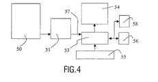
図4を参照すると、デジタル画像シーケンスを取得する手段と、上述した処理ステップによるこれらデータを処理するための観察システム120とを有している。この医療用検査装置は、画像データを観察システム120に提供するための手段を有しており、これは、画像データを、表示手段及び/又は保存手段130、140へと提供するための少なくとも一つの出力106を有している。表示及び保存手段は、代替的に外部保存手段であってもよい。この画像観察システム120は、適切にプログラムされたワークステーションのコンピューター110又は本発明の方法ステップの機能を実行すべく配置されたLUTs、メモリ、フィルター、論理演算子などの、回路手段を有する専用プロセッサーを有していてもよい。ワークステーション110は、キーボード131及びマウス132を有していてもよい。この医療検査装置150は、標準的な超音波装置であってもよい。観察システム120は、上記の処理システムの手段を演算することにより実行されるプログラム支持を有するコンピュータープログラム製品を使用してもよい。 Referring to FIG. 4, it has means for acquiring a digital image sequence and an observation system 120 for processing these data according to the processing steps described above. This medical examination apparatus has means for providing image data to the observation system 120, which is at least one for providing image data to the display means and / or storage means 130, 140. There are two outputs 106. The display and storage means may alternatively be an external storage means. The image viewing system 120 is a dedicated processor having circuit means, such as LUTs, memories, filters, logical operators, etc. arranged to perform the functions of a computer 110 of a suitably programmed workstation or method steps of the present invention. You may have. The workstation 110 may have a keyboard 131 and a mouse 132. The medical examination apparatus 150 may be a standard ultrasonic apparatus. The observation system 120 may use a computer program product with program support that is executed by computing the means of the processing system described above.
Claims (8)
Translated fromJapanese体器官内の流動に関する三次元カラーフロー画像のシーケンスを取得し;
前記三次元画像における前記流動の速度値を評価し;
前記の流動の速度値をセグメント化することにより等速度表面を構築し;
前記等速度表面にて範囲を規定される前記容量を演算し;且つ
前記流動が伝播する前記体器官の前記開口部の表面を演算すべく、セグメント化された表面から演算された前記の流動速度値と前記容量とを使用する;
ステップを実行する手段を有する、医療用超音波観察システム。A medical ultrasound observation system that processes a sequence of three-dimensional ultrasound images to perform a quantitative calculation of flow in a body organ:
Obtaining a sequence of 3D color flow images of the flow in the body organ;
Evaluating the velocity value of the flow in the three-dimensional image;
Construct an isokinetic surface by segmenting the flow velocity values;
The flow velocity calculated from a segmented surface to calculate the volume delimited by the constant velocity surface; and to calculate the surface of the opening of the body organ through which the flow propagates Use the value and the capacity;
A medical ultrasonic observation system having means for executing steps.
前記開口部に対する前記流動の伝播の上流の等速度表面における前記の流動の速度値、
前記のセグメント化された等速度表面から演算された前記容量、及び
前記の流動の伝播の前記方向における前記開口部を介した前記流動の前記ピーク速度、
の関数として、前記流動が伝播する、前記の開口部の表面を演算する;
ステップを実行する手段を有することを特徴とする請求項1に記載の医療用超音波観察システム。Measuring the peak velocity of flow through the opening in the direction of the flow; and the velocity value of the flow at a constant velocity surface upstream of the flow propagation to the opening;
The volume calculated from the segmented isokinetic surface, and the peak velocity of the flow through the opening in the direction of the flow propagation,
Calculating the surface of the opening through which the flow propagates as a function of
The medical ultrasonic observation system according to claim 1, further comprising means for executing steps.
請求項1乃至6のいずれか一項に記載の手段を有し、
前記医療用デジタル画像データにアクセスし、
前記画像データを処理し、且つ
前記の処理された画像を表示する手段を有する、
超音波検査装置。Having means for acquiring medical image data;
It has a means as described in any one of Claims 1 thru / or 6,
Accessing the medical digital image data;
Means for processing the image data and displaying the processed image;
Ultrasonic inspection device.
Applications Claiming Priority (2)
| Application Number | Priority Date | Filing Date | Title |
|---|---|---|---|
| EP01403392 | 2001-12-28 | ||
| PCT/IB2002/005356WO2003060553A2 (en) | 2001-12-28 | 2002-12-11 | Viewing system having means for processing a sequence of ultrasound images for performing a quantitative estimation of a flow in a body organ |
Publications (2)
| Publication Number | Publication Date |
|---|---|
| JP2005514997Atrue JP2005514997A (en) | 2005-05-26 |
| JP2005514997A5 JP2005514997A5 (en) | 2006-02-09 |
Family
ID=8183067
Family Applications (1)
| Application Number | Title | Priority Date | Filing Date |
|---|---|---|---|
| JP2003560595APendingJP2005514997A (en) | 2001-12-28 | 2002-12-11 | Observation system having means for processing an ultrasound image sequence for performing a quantitative calculation of flow in a body organ |
Country Status (6)
| Country | Link |
|---|---|
| US (1) | US7229412B2 (en) |
| EP (1) | EP1481261A1 (en) |
| JP (1) | JP2005514997A (en) |
| CN (1) | CN1610841A (en) |
| AU (1) | AU2002353325A1 (en) |
| WO (1) | WO2003060553A2 (en) |
Cited By (6)
| Publication number | Priority date | Publication date | Assignee | Title |
|---|---|---|---|---|
| JP2011172933A (en)* | 2010-02-25 | 2011-09-08 | Siemens Medical Solutions Usa Inc | Volumetric quantification method in medical diagnostic ultrasound and computer readable storage medium having stored therein data representing instructions executable by programmed processor for volumetric quantification in medical diagnostic ultrasound |
| JP2012506271A (en)* | 2008-10-24 | 2012-03-15 | トムテック イメージング システムズ ゲゼルシャフト ミット ベシュレンクテル ハフツング | 3D derivation and 3D PISA flow measurement of the proximal constant velocity shell in the proximal flow convergence region |
| WO2013057999A1 (en)* | 2011-10-20 | 2013-04-25 | 日立アロカメディカル株式会社 | Ultrasound imaging equipment and method |
| JP2014500117A (en)* | 2010-12-23 | 2014-01-09 | コーニンクレッカ フィリップス エヌ ヴェ | Analysis of mitral regurgitation from slit opening by ultrasonic imaging |
| JP2018530493A (en)* | 2015-10-16 | 2018-10-18 | パルフィンガー アクチエンゲゼルシャフトPalfinger Ag | Device comprising a control unit and a mobile control module |
| JP2024534031A (en)* | 2021-08-17 | 2024-09-18 | コーニンクレッカ フィリップス エヌ ヴェ | Ultrasound Imaging for Visualization and Quantification of Mitral Regurgitation |
Families Citing this family (17)
| Publication number | Priority date | Publication date | Assignee | Title |
|---|---|---|---|---|
| AU2003901366A0 (en)* | 2003-03-25 | 2003-04-10 | Uscom Pty Ltd | Method for tracing geometric elements |
| US7439977B2 (en)* | 2003-08-27 | 2008-10-21 | Komarechka Robert G | Method of displaying three-dimensional vector orientations on a two-dimensional surface |
| JP2008183022A (en)* | 2007-01-26 | 2008-08-14 | Ge Medical Systems Global Technology Co Llc | Image processing device, image processing method, magnetic resonance imaging device and program |
| US8425422B2 (en)* | 2008-06-06 | 2013-04-23 | Siemens Medical Solutions Usa, Inc. | Adaptive volume rendering for ultrasound color flow diagnostic imaging |
| US8200466B2 (en) | 2008-07-21 | 2012-06-12 | The Board Of Trustees Of The Leland Stanford Junior University | Method for tuning patient-specific cardiovascular simulations |
| US9405886B2 (en) | 2009-03-17 | 2016-08-02 | The Board Of Trustees Of The Leland Stanford Junior University | Method for determining cardiovascular information |
| US9028413B2 (en) | 2010-03-08 | 2015-05-12 | Siemens Medical Solutions Usa, Inc. | Prediction-based flow estimation for ultrasound diagnostic imaging |
| US8157742B2 (en) | 2010-08-12 | 2012-04-17 | Heartflow, Inc. | Method and system for patient-specific modeling of blood flow |
| US8315812B2 (en) | 2010-08-12 | 2012-11-20 | Heartflow, Inc. | Method and system for patient-specific modeling of blood flow |
| US20120084064A1 (en)* | 2010-09-29 | 2012-04-05 | Nutech Ventures, Inc. | Model-based systems and methods for analyzing and predicting outcomes of vascular interventions and reconstructions |
| JP5990536B2 (en)* | 2010-12-23 | 2016-09-14 | コーニンクレッカ フィリップス エヌ ヴェKoninklijke Philips N.V. | Wall filter for backflow ultrasonic analysis of mitral valve |
| EP2654573B1 (en)* | 2010-12-23 | 2018-07-25 | Koninklijke Philips N.V. | Automated identification of the location of a regurgitant orifice of a mitral valve in an ultrasound image |
| US8548778B1 (en) | 2012-05-14 | 2013-10-01 | Heartflow, Inc. | Method and system for providing information from a patient-specific model of blood flow |
| US10271817B2 (en)* | 2014-06-23 | 2019-04-30 | Siemens Medical Solutions Usa, Inc. | Valve regurgitant detection for echocardiography |
| CN112690814B (en)* | 2020-11-06 | 2022-10-14 | 杭州阿特瑞科技有限公司 | A Low-Error Measurement of Coronary Fractional Flow Reserve |
| CN115670511A (en)* | 2021-07-23 | 2023-02-03 | 深圳迈瑞生物医疗电子股份有限公司 | Blood flow measurement method and ultrasound imaging system based on ultrasound |
| CN115587992B (en)* | 2022-10-21 | 2025-06-10 | 复旦大学附属中山医院 | M-type PISA quantitative method and electronic device for atrioventricular valve regurgitation volume |
- 2002
- 2002-12-11JPJP2003560595Apatent/JP2005514997A/enactivePending
- 2002-12-11WOPCT/IB2002/005356patent/WO2003060553A2/ennot_activeApplication Discontinuation
- 2002-12-11AUAU2002353325Apatent/AU2002353325A1/ennot_activeAbandoned
- 2002-12-11EPEP02788346Apatent/EP1481261A1/ennot_activeCeased
- 2002-12-11CNCNA028264401Apatent/CN1610841A/enactivePending
- 2002-12-11USUS10/499,938patent/US7229412B2/ennot_activeExpired - Fee Related
Cited By (9)
| Publication number | Priority date | Publication date | Assignee | Title |
|---|---|---|---|---|
| JP2012506271A (en)* | 2008-10-24 | 2012-03-15 | トムテック イメージング システムズ ゲゼルシャフト ミット ベシュレンクテル ハフツング | 3D derivation and 3D PISA flow measurement of the proximal constant velocity shell in the proximal flow convergence region |
| JP2011172933A (en)* | 2010-02-25 | 2011-09-08 | Siemens Medical Solutions Usa Inc | Volumetric quantification method in medical diagnostic ultrasound and computer readable storage medium having stored therein data representing instructions executable by programmed processor for volumetric quantification in medical diagnostic ultrasound |
| JP2014500117A (en)* | 2010-12-23 | 2014-01-09 | コーニンクレッカ フィリップス エヌ ヴェ | Analysis of mitral regurgitation from slit opening by ultrasonic imaging |
| WO2013057999A1 (en)* | 2011-10-20 | 2013-04-25 | 日立アロカメディカル株式会社 | Ultrasound imaging equipment and method |
| JPWO2013057999A1 (en)* | 2011-10-20 | 2015-04-02 | 日立アロカメディカル株式会社 | Ultrasonic imaging apparatus and method |
| US9538989B2 (en) | 2011-10-20 | 2017-01-10 | Hitachi, Ltd. | Ultrasound imaging equipment and method |
| JP2018530493A (en)* | 2015-10-16 | 2018-10-18 | パルフィンガー アクチエンゲゼルシャフトPalfinger Ag | Device comprising a control unit and a mobile control module |
| JP7003043B2 (en) | 2015-10-16 | 2022-01-20 | パルフィンガー アクチエンゲゼルシャフト | A device consisting of a control unit and a mobile control module |
| JP2024534031A (en)* | 2021-08-17 | 2024-09-18 | コーニンクレッカ フィリップス エヌ ヴェ | Ultrasound Imaging for Visualization and Quantification of Mitral Regurgitation |
Also Published As
| Publication number | Publication date |
|---|---|
| EP1481261A1 (en) | 2004-12-01 |
| WO2003060553A2 (en) | 2003-07-24 |
| CN1610841A (en) | 2005-04-27 |
| AU2002353325A1 (en) | 2003-07-30 |
| US20050165308A1 (en) | 2005-07-28 |
| US7229412B2 (en) | 2007-06-12 |
Similar Documents
| Publication | Publication Date | Title |
|---|---|---|
| JP2005514997A (en) | Observation system having means for processing an ultrasound image sequence for performing a quantitative calculation of flow in a body organ | |
| US6106466A (en) | Automated delineation of heart contours from images using reconstruction-based modeling | |
| CN102763135B (en) | Methods for Automatic Segmentation and Time Tracking | |
| Suhling et al. | Myocardial motion analysis from B-mode echocardiograms | |
| US7925064B2 (en) | Automatic multi-dimensional intravascular ultrasound image segmentation method | |
| US6251072B1 (en) | Semi-automated segmentation method for 3-dimensional ultrasound | |
| WO2019109607A1 (en) | Fast calculation method and system employing plaque stability index of medical image sequence | |
| US9129392B2 (en) | Automatic quantification of mitral valve dynamics with real-time 3D ultrasound | |
| JP7672398B2 (en) | Systems and methods for image optimization - Patents.com | |
| JP2024534031A (en) | Ultrasound Imaging for Visualization and Quantification of Mitral Regurgitation | |
| Almeida et al. | Left-atrial segmentation from 3-D ultrasound using B-spline explicit active surfaces with scale uncoupling | |
| JP2023521817A (en) | System and method for non-invasive pressure measurement | |
| Wolf et al. | ROPES: A semiautomated segmentation method for accelerated analysis of three-dimensional echocardiographic data | |
| CN112220493A (en) | Carotid arteriosclerosis assessment method | |
| JP5885234B2 (en) | Image analysis method in disease determination apparatus and ultrasonic image forming apparatus | |
| CN118298004B (en) | Heart function assessment method and system based on three-dimensional echocardiography | |
| JP7602015B2 (en) | Ultrasonic Methods | |
| Angelini et al. | Comparison of segmentation methods for analysis of endocardial wall motion with real-time three-dimensional ultrasound | |
| Gutierrez et al. | CAD of cardiovascular diseases | |
| Tavakoli et al. | Comparison of myocardial motion estimation methods based on simulated echocardiographic B-mode and RF data | |
| CN116033874A (en) | System and method for measuring cardiac stiffness | |
| JP2022171345A (en) | Medical image processing device, medical image processing method and program | |
| Manandhar et al. | An automated robust segmentation method for intravascular ultrasound images | |
| Ličev et al. | Search and Implementation of Optimization Algorithms in Analysis of Ultrasonic Pictures in Neurology | |
| Harabis et al. | Perfusion Curves Modelling for Evaluating of Ultrasound Image Registration |
Legal Events
| Date | Code | Title | Description |
|---|---|---|---|
| A521 | Request for written amendment filed | Free format text:JAPANESE INTERMEDIATE CODE: A523 Effective date:20051209 | |
| A621 | Written request for application examination | Free format text:JAPANESE INTERMEDIATE CODE: A621 Effective date:20051209 | |
| A977 | Report on retrieval | Free format text:JAPANESE INTERMEDIATE CODE: A971007 Effective date:20081001 | |
| A131 | Notification of reasons for refusal | Free format text:JAPANESE INTERMEDIATE CODE: A131 Effective date:20081024 | |
| A601 | Written request for extension of time | Free format text:JAPANESE INTERMEDIATE CODE: A601 Effective date:20090123 | |
| A602 | Written permission of extension of time | Free format text:JAPANESE INTERMEDIATE CODE: A602 Effective date:20090130 | |
| A02 | Decision of refusal | Free format text:JAPANESE INTERMEDIATE CODE: A02 Effective date:20090721 |