JP2005514273A - Sealing pharmaceutical preparations in packaging - Google Patents
Sealing pharmaceutical preparations in packagingDownload PDFInfo
- Publication number
- JP2005514273A JP2005514273AJP2003557896AJP2003557896AJP2005514273AJP 2005514273 AJP2005514273 AJP 2005514273AJP 2003557896 AJP2003557896 AJP 2003557896AJP 2003557896 AJP2003557896 AJP 2003557896AJP 2005514273 AJP2005514273 AJP 2005514273A
- Authority
- JP
- Japan
- Prior art keywords
- layer
- roller
- pharmaceutical formulation
- pharmaceutical
- sealing
- Prior art date
- Legal status (The legal status is an assumption and is not a legal conclusion. Google has not performed a legal analysis and makes no representation as to the accuracy of the status listed.)
- Pending
Links
- 238000007789sealingMethods0.000titleclaimsabstractdescription80
- 238000004806packaging method and processMethods0.000titledescription13
- 239000000825pharmaceutical preparationSubstances0.000titledescription5
- 239000008194pharmaceutical compositionSubstances0.000claimsabstractdescription88
- 238000010438heat treatmentMethods0.000claimsabstractdescription43
- 238000000034methodMethods0.000claimsdescription50
- 239000000843powderSubstances0.000claimsdescription26
- 229910052751metalInorganic materials0.000claimsdescription15
- 239000002184metalSubstances0.000claimsdescription15
- 239000002775capsuleSubstances0.000claimsdescription11
- 238000009512pharmaceutical packagingMethods0.000claimsdescription4
- 238000004519manufacturing processMethods0.000claims1
- 238000003825pressingMethods0.000claims1
- 241001131688Coracias garrulusSpecies0.000description125
- 230000008569processEffects0.000description27
- 239000013543active substanceSubstances0.000description22
- -1blistersSubstances0.000description17
- 239000000546pharmaceutical excipientSubstances0.000description16
- 239000000463materialSubstances0.000description15
- 229940079593drugDrugs0.000description14
- 239000003814drugSubstances0.000description14
- 239000002245particleSubstances0.000description14
- 230000006870functionEffects0.000description10
- 239000000203mixtureSubstances0.000description8
- 235000001014amino acidNutrition0.000description7
- 229940024606amino acidDrugs0.000description7
- 150000001413amino acidsChemical class0.000description7
- 108090000765processed proteins & peptidesProteins0.000description7
- 108090000623proteins and genesProteins0.000description7
- NOESYZHRGYRDHS-UHFFFAOYSA-NinsulinChemical compoundN1C(=O)C(NC(=O)C(CCC(N)=O)NC(=O)C(CCC(O)=O)NC(=O)C(C(C)C)NC(=O)C(NC(=O)CN)C(C)CC)CSSCC(C(NC(CO)C(=O)NC(CC(C)C)C(=O)NC(CC=2C=CC(O)=CC=2)C(=O)NC(CCC(N)=O)C(=O)NC(CC(C)C)C(=O)NC(CCC(O)=O)C(=O)NC(CC(N)=O)C(=O)NC(CC=2C=CC(O)=CC=2)C(=O)NC(CSSCC(NC(=O)C(C(C)C)NC(=O)C(CC(C)C)NC(=O)C(CC=2C=CC(O)=CC=2)NC(=O)C(CC(C)C)NC(=O)C(C)NC(=O)C(CCC(O)=O)NC(=O)C(C(C)C)NC(=O)C(CC(C)C)NC(=O)C(CC=2NC=NC=2)NC(=O)C(CO)NC(=O)CNC2=O)C(=O)NCC(=O)NC(CCC(O)=O)C(=O)NC(CCCNC(N)=N)C(=O)NCC(=O)NC(CC=3C=CC=CC=3)C(=O)NC(CC=3C=CC=CC=3)C(=O)NC(CC=3C=CC(O)=CC=3)C(=O)NC(C(C)O)C(=O)N3C(CCC3)C(=O)NC(CCCCN)C(=O)NC(C)C(O)=O)C(=O)NC(CC(N)=O)C(O)=O)=O)NC(=O)C(C(C)CC)NC(=O)C(CO)NC(=O)C(C(C)O)NC(=O)C1CSSCC2NC(=O)C(CC(C)C)NC(=O)C(NC(=O)C(CCC(N)=O)NC(=O)C(CC(N)=O)NC(=O)C(NC(=O)C(N)CC=1C=CC=CC=1)C(C)C)CC1=CN=CN1NOESYZHRGYRDHS-UHFFFAOYSA-N0.000description6
- 235000018102proteinsNutrition0.000description6
- 102000004169proteins and genesHuman genes0.000description6
- QTBSBXVTEAMEQO-UHFFFAOYSA-Nacetic acidSubstancesCC(O)=OQTBSBXVTEAMEQO-UHFFFAOYSA-N0.000description5
- 230000015556catabolic processEffects0.000description5
- 239000003795chemical substances by applicationSubstances0.000description5
- 238000007906compressionMethods0.000description5
- 230000006835compressionEffects0.000description5
- 238000006731degradation reactionMethods0.000description5
- 210000004072lungAnatomy0.000description5
- 230000007246mechanismEffects0.000description5
- 102000004196processed proteins & peptidesHuman genes0.000description5
- 239000003566sealing materialSubstances0.000description5
- JGSARLDLIJGVTE-MBNYWOFBSA-NPenicillin GChemical compoundN([C@H]1[C@H]2SC([C@@H](N2C1=O)C(O)=O)(C)C)C(=O)CC1=CC=CC=C1JGSARLDLIJGVTE-MBNYWOFBSA-N0.000description4
- 241000700605VirusesSpecies0.000description4
- 150000001875compoundsChemical class0.000description4
- 230000000694effectsEffects0.000description4
- 230000002829reductive effectEffects0.000description4
- 238000003860storageMethods0.000description4
- 235000000346sugarNutrition0.000description4
- 238000012360testing methodMethods0.000description4
- 229960005486vaccineDrugs0.000description4
- 102000008100Human Serum AlbuminHuman genes0.000description3
- 108091006905Human Serum AlbuminProteins0.000description3
- 229930182555PenicillinNatural products0.000description3
- 239000000443aerosolSubstances0.000description3
- 238000012387aerosolizationMethods0.000description3
- 229910052782aluminiumInorganic materials0.000description3
- XAGFODPZIPBFFR-UHFFFAOYSA-NaluminiumChemical compound[Al]XAGFODPZIPBFFR-UHFFFAOYSA-N0.000description3
- 230000009286beneficial effectEffects0.000description3
- 239000006172buffering agentSubstances0.000description3
- KRKNYBCHXYNGOX-UHFFFAOYSA-Ncitric acidChemical compoundOC(=O)CC(O)(C(O)=O)CC(O)=OKRKNYBCHXYNGOX-UHFFFAOYSA-N0.000description3
- 238000004590computer programMethods0.000description3
- 235000015872dietary supplementNutrition0.000description3
- 230000002209hydrophobic effectEffects0.000description3
- 239000004922lacquerSubstances0.000description3
- 150000007523nucleic acidsChemical class0.000description3
- 229940124531pharmaceutical excipientDrugs0.000description3
- 229920001223polyethylene glycolPolymers0.000description3
- 229920001282polysaccharidePolymers0.000description3
- 239000004800polyvinyl chlorideSubstances0.000description3
- 229920000915polyvinyl chloridePolymers0.000description3
- 150000003839saltsChemical class0.000description3
- 150000008163sugarsChemical class0.000description3
- DLFVBJFMPXGRIB-UHFFFAOYSA-NAcetamideChemical compoundCC(N)=ODLFVBJFMPXGRIB-UHFFFAOYSA-N0.000description2
- CIWBSHSKHKDKBQ-JLAZNSOCSA-NAscorbic acidChemical compoundOC[C@H](O)[C@H]1OC(=O)C(O)=C1OCIWBSHSKHKDKBQ-JLAZNSOCSA-N0.000description2
- 229930186147CephalosporinNatural products0.000description2
- 102100022641Coagulation factor IXHuman genes0.000description2
- 229920000858CyclodextrinPolymers0.000description2
- RGHNJXZEOKUKBD-SQOUGZDYSA-ND-gluconic acidChemical compoundOC[C@@H](O)[C@@H](O)[C@H](O)[C@@H](O)C(O)=ORGHNJXZEOKUKBD-SQOUGZDYSA-N0.000description2
- ULGZDMOVFRHVEP-RWJQBGPGSA-NErythromycinChemical compoundO([C@@H]1[C@@H](C)C(=O)O[C@@H]([C@@]([C@H](O)[C@@H](C)C(=O)[C@H](C)C[C@@](C)(O)[C@H](O[C@H]2[C@@H]([C@H](C[C@@H](C)O2)N(C)C)O)[C@H]1C)(C)O)CC)[C@H]1C[C@@](C)(OC)[C@@H](O)[C@H](C)O1ULGZDMOVFRHVEP-RWJQBGPGSA-N0.000description2
- 102000003951ErythropoietinHuman genes0.000description2
- 108090000394ErythropoietinProteins0.000description2
- 108010076282Factor IXProteins0.000description2
- 102000003972Fibroblast growth factor 7Human genes0.000description2
- 108090000385Fibroblast growth factor 7Proteins0.000description2
- 102000012673Follicle Stimulating HormoneHuman genes0.000description2
- 108010079345Follicle Stimulating HormoneProteins0.000description2
- DHMQDGOQFOQNFH-UHFFFAOYSA-NGlycineChemical compoundNCC(O)=ODHMQDGOQFOQNFH-UHFFFAOYSA-N0.000description2
- 102000004269Granulocyte Colony-Stimulating FactorHuman genes0.000description2
- 108010017080Granulocyte Colony-Stimulating FactorProteins0.000description2
- 108010017213Granulocyte-Macrophage Colony-Stimulating FactorProteins0.000description2
- 102100039620Granulocyte-macrophage colony-stimulating factorHuman genes0.000description2
- 102000038461Growth Hormone-Releasing HormoneHuman genes0.000description2
- 239000000095Growth Hormone-Releasing HormoneSubstances0.000description2
- HTTJABKRGRZYRN-UHFFFAOYSA-NHeparinChemical compoundOC1C(NC(=O)C)C(O)OC(COS(O)(=O)=O)C1OC1C(OS(O)(=O)=O)C(O)C(OC2C(C(OS(O)(=O)=O)C(OC3C(C(O)C(O)C(O3)C(O)=O)OS(O)(=O)=O)C(CO)O2)NS(O)(=O)=O)C(C(O)=O)O1HTTJABKRGRZYRN-UHFFFAOYSA-N0.000description2
- NTYJJOPFIAHURM-UHFFFAOYSA-NHistamineChemical compoundNCCC1=CN=CN1NTYJJOPFIAHURM-UHFFFAOYSA-N0.000description2
- 102000002265Human Growth HormoneHuman genes0.000description2
- 108010000521Human Growth HormoneProteins0.000description2
- 239000000854Human Growth HormoneSubstances0.000description2
- 102000004877InsulinHuman genes0.000description2
- 108090001061InsulinProteins0.000description2
- 108090000723Insulin-Like Growth Factor IProteins0.000description2
- 102000014429Insulin-like growth factorHuman genes0.000description2
- QNAYBMKLOCPYGJ-REOHCLBHSA-NL-alanineChemical compoundC[C@H](N)C(O)=OQNAYBMKLOCPYGJ-REOHCLBHSA-N0.000description2
- HNDVDQJCIGZPNO-YFKPBYRVSA-NL-histidineChemical compoundOC(=O)[C@@H](N)CC1=CN=CN1HNDVDQJCIGZPNO-YFKPBYRVSA-N0.000description2
- AGPKZVBTJJNPAG-WHFBIAKZSA-NL-isoleucineChemical compoundCC[C@H](C)[C@H](N)C(O)=OAGPKZVBTJJNPAG-WHFBIAKZSA-N0.000description2
- ROHFNLRQFUQHCH-YFKPBYRVSA-NL-leucineChemical compoundCC(C)C[C@H](N)C(O)=OROHFNLRQFUQHCH-YFKPBYRVSA-N0.000description2
- FFEARJCKVFRZRR-BYPYZUCNSA-NL-methionineChemical compoundCSCC[C@H](N)C(O)=OFFEARJCKVFRZRR-BYPYZUCNSA-N0.000description2
- COLNVLDHVKWLRT-QMMMGPOBSA-NL-phenylalanineChemical compoundOC(=O)[C@@H](N)CC1=CC=CC=C1COLNVLDHVKWLRT-QMMMGPOBSA-N0.000description2
- QIVBCDIJIAJPQS-VIFPVBQESA-NL-tryptophaneChemical compoundC1=CC=C2C(C[C@H](N)C(O)=O)=CNC2=C1QIVBCDIJIAJPQS-VIFPVBQESA-N0.000description2
- OUYCCCASQSFEME-QMMMGPOBSA-NL-tyrosineChemical compoundOC(=O)[C@@H](N)CC1=CC=C(O)C=C1OUYCCCASQSFEME-QMMMGPOBSA-N0.000description2
- KZSNJWFQEVHDMF-BYPYZUCNSA-NL-valineChemical compoundCC(C)[C@H](N)C(O)=OKZSNJWFQEVHDMF-BYPYZUCNSA-N0.000description2
- ROHFNLRQFUQHCH-UHFFFAOYSA-NLeucineNatural productsCC(C)CC(N)C(O)=OROHFNLRQFUQHCH-UHFFFAOYSA-N0.000description2
- 102000007651Macrophage Colony-Stimulating FactorHuman genes0.000description2
- 108010046938Macrophage Colony-Stimulating FactorProteins0.000description2
- 108010025020Nerve Growth FactorProteins0.000description2
- 102000015336Nerve Growth FactorHuman genes0.000description2
- 102400000058Neuregulin-1Human genes0.000description2
- 108090000556Neuregulin-1Proteins0.000description2
- 229910019142PO4Inorganic materials0.000description2
- 108010087702PenicillinaseProteins0.000description2
- 239000004952PolyamideSubstances0.000description2
- FAPWRFPIFSIZLT-UHFFFAOYSA-MSodium chlorideChemical compound[Na+].[Cl-]FAPWRFPIFSIZLT-UHFFFAOYSA-M0.000description2
- 101710142969SomatoliberinProteins0.000description2
- 102000036693ThrombopoietinHuman genes0.000description2
- 108010041111ThrombopoietinProteins0.000description2
- QIVBCDIJIAJPQS-UHFFFAOYSA-NTryptophanNatural productsC1=CC=C2C(CC(N)C(O)=O)=CNC2=C1QIVBCDIJIAJPQS-UHFFFAOYSA-N0.000description2
- 108060008682Tumor Necrosis FactorProteins0.000description2
- KZSNJWFQEVHDMF-UHFFFAOYSA-NValineNatural productsCC(C)C(N)C(O)=OKZSNJWFQEVHDMF-UHFFFAOYSA-N0.000description2
- TVXBFESIOXBWNM-UHFFFAOYSA-NXylitolNatural productsOCCC(O)C(O)C(O)CCOTVXBFESIOXBWNM-UHFFFAOYSA-N0.000description2
- 239000000654additiveSubstances0.000description2
- 235000004279alanineNutrition0.000description2
- 102000015395alpha 1-AntitrypsinHuman genes0.000description2
- 108010050122alpha 1-AntitrypsinProteins0.000description2
- 239000003242anti bacterial agentSubstances0.000description2
- 239000001961anticonvulsive agentSubstances0.000description2
- 239000002246antineoplastic agentSubstances0.000description2
- 229940041181antineoplastic drugDrugs0.000description2
- 239000003963antioxidant agentSubstances0.000description2
- 235000006708antioxidantsNutrition0.000description2
- 229920001222biopolymerPolymers0.000description2
- 150000001720carbohydratesChemical class0.000description2
- 235000014633carbohydratesNutrition0.000description2
- 229940124587cephalosporinDrugs0.000description2
- 150000001780cephalosporinsChemical class0.000description2
- HVYWMOMLDIMFJA-DPAQBDIFSA-NcholesterolChemical compoundC1C=C2C[C@@H](O)CC[C@]2(C)[C@@H]2[C@@H]1[C@@H]1CC[C@H]([C@H](C)CCCC(C)C)[C@@]1(C)CC2HVYWMOMLDIMFJA-DPAQBDIFSA-N0.000description2
- MYSWGUAQZAJSOK-UHFFFAOYSA-NciprofloxacinChemical compoundC12=CC(N3CCNCC3)=C(F)C=C2C(=O)C(C(=O)O)=CN1C1CC1MYSWGUAQZAJSOK-UHFFFAOYSA-N0.000description2
- 238000004891communicationMethods0.000description2
- 238000009826distributionMethods0.000description2
- 230000002708enhancing effectEffects0.000description2
- 229940105423erythropoietinDrugs0.000description2
- 229960004222factor ixDrugs0.000description2
- 229940028334follicle stimulating hormoneDrugs0.000description2
- 238000009472formulationMethods0.000description2
- 150000004676glycansChemical class0.000description2
- KWIUHFFTVRNATP-UHFFFAOYSA-Nglycine betaineChemical compoundC[N+](C)(C)CC([O-])=OKWIUHFFTVRNATP-UHFFFAOYSA-N0.000description2
- 239000003102growth factorSubstances0.000description2
- HNDVDQJCIGZPNO-UHFFFAOYSA-NhistidineNatural productsOC(=O)C(N)CC1=CN=CN1HNDVDQJCIGZPNO-UHFFFAOYSA-N0.000description2
- 230000001965increasing effectEffects0.000description2
- 239000003112inhibitorSubstances0.000description2
- 229940125396insulinDrugs0.000description2
- AGPKZVBTJJNPAG-UHFFFAOYSA-NisoleucineNatural productsCCC(C)C(N)C(O)=OAGPKZVBTJJNPAG-UHFFFAOYSA-N0.000description2
- 229960000310isoleucineDrugs0.000description2
- 150000002632lipidsChemical class0.000description2
- HEBKCHPVOIAQTA-UHFFFAOYSA-Nmeso ribitolNatural productsOCC(O)C(O)C(O)COHEBKCHPVOIAQTA-UHFFFAOYSA-N0.000description2
- 229930182817methionineNatural products0.000description2
- 230000004048modificationEffects0.000description2
- 238000012986modificationMethods0.000description2
- 229940053128nerve growth factorDrugs0.000description2
- 108020004707nucleic acidsProteins0.000description2
- 102000039446nucleic acidsHuman genes0.000description2
- 229940049954penicillinDrugs0.000description2
- 229950009506penicillinaseDrugs0.000description2
- 230000000144pharmacologic effectEffects0.000description2
- COLNVLDHVKWLRT-UHFFFAOYSA-NphenylalanineNatural productsOC(=O)C(N)CC1=CC=CC=C1COLNVLDHVKWLRT-UHFFFAOYSA-N0.000description2
- NBIIXXVUZAFLBC-UHFFFAOYSA-KphosphateChemical compound[O-]P([O-])([O-])=ONBIIXXVUZAFLBC-UHFFFAOYSA-K0.000description2
- 239000010452phosphateSubstances0.000description2
- 229920003229poly(methyl methacrylate)Polymers0.000description2
- 229920002647polyamidePolymers0.000description2
- 239000002861polymer materialSubstances0.000description2
- 239000004926polymethyl methacrylateSubstances0.000description2
- 229920001184polypeptidePolymers0.000description2
- 239000005017polysaccharideSubstances0.000description2
- OXCMYAYHXIHQOA-UHFFFAOYSA-Npotassium;[2-butyl-5-chloro-3-[[4-[2-(1,2,4-triaza-3-azanidacyclopenta-1,4-dien-5-yl)phenyl]phenyl]methyl]imidazol-4-yl]methanolChemical compound[K+].CCCCC1=NC(Cl)=C(CO)N1CC1=CC=C(C=2C(=CC=CC=2)C2=N[N-]N=N2)C=C1OXCMYAYHXIHQOA-UHFFFAOYSA-N0.000description2
- 230000000241respiratory effectEffects0.000description2
- 230000004044responseEffects0.000description2
- NHXLMOGPVYXJNR-ATOGVRKGSA-NsomatostatinChemical classC([C@H]1C(=O)N[C@H](C(N[C@@H](CO)C(=O)N[C@@H](CSSC[C@@H](C(=O)N[C@@H](CCCCN)C(=O)N[C@@H](CC(N)=O)C(=O)N[C@@H](CC=2C=CC=CC=2)C(=O)N[C@@H](CC=2C=CC=CC=2)C(=O)N[C@@H](CC=2C3=CC=CC=C3NC=2)C(=O)N[C@@H](CCCCN)C(=O)N[C@H](C(=O)N1)[C@@H](C)O)NC(=O)CNC(=O)[C@H](C)N)C(O)=O)=O)[C@H](O)C)C1=CC=CC=C1NHXLMOGPVYXJNR-ATOGVRKGSA-N0.000description2
- 150000003431steroidsChemical class0.000description2
- UCSJYZPVAKXKNQ-HZYVHMACSA-NstreptomycinChemical compoundCN[C@H]1[C@H](O)[C@@H](O)[C@H](CO)O[C@H]1O[C@@H]1[C@](C=O)(O)[C@H](C)O[C@H]1O[C@@H]1[C@@H](NC(N)=N)[C@H](O)[C@@H](NC(N)=N)[C@H](O)[C@H]1OUCSJYZPVAKXKNQ-HZYVHMACSA-N0.000description2
- 239000000126substanceSubstances0.000description2
- 150000005846sugar alcoholsChemical class0.000description2
- 102000003390tumor necrosis factorHuman genes0.000description2
- OUYCCCASQSFEME-UHFFFAOYSA-NtyrosineNatural productsOC(=O)C(N)CC1=CC=C(O)C=C1OUYCCCASQSFEME-UHFFFAOYSA-N0.000description2
- 239000004474valineSubstances0.000description2
- 239000000811xylitolSubstances0.000description2
- 235000010447xylitolNutrition0.000description2
- HEBKCHPVOIAQTA-SCDXWVJYSA-NxylitolChemical compoundOC[C@H](O)[C@@H](O)[C@H](O)COHEBKCHPVOIAQTA-SCDXWVJYSA-N0.000description2
- 229960002675xylitolDrugs0.000description2
- HDTRYLNUVZCQOY-UHFFFAOYSA-Nα-D-glucopyranosyl-α-D-glucopyranosideNatural productsOC1C(O)C(O)C(CO)OC1OC1C(O)C(O)C(O)C(CO)O1HDTRYLNUVZCQOY-UHFFFAOYSA-N0.000description1
- JNYAEWCLZODPBN-JGWLITMVSA-N(2r,3r,4s)-2-[(1r)-1,2-dihydroxyethyl]oxolane-3,4-diolChemical classOC[C@@H](O)[C@H]1OC[C@H](O)[C@H]1OJNYAEWCLZODPBN-JGWLITMVSA-N0.000description1
- DEQANNDTNATYII-OULOTJBUSA-N(4r,7s,10s,13r,16s,19r)-10-(4-aminobutyl)-19-[[(2r)-2-amino-3-phenylpropanoyl]amino]-16-benzyl-n-[(2r,3r)-1,3-dihydroxybutan-2-yl]-7-[(1r)-1-hydroxyethyl]-13-(1h-indol-3-ylmethyl)-6,9,12,15,18-pentaoxo-1,2-dithia-5,8,11,14,17-pentazacycloicosane-4-carboxaChemical compoundC([C@@H](N)C(=O)N[C@H]1CSSC[C@H](NC(=O)[C@H]([C@@H](C)O)NC(=O)[C@H](CCCCN)NC(=O)[C@@H](CC=2C3=CC=CC=C3NC=2)NC(=O)[C@H](CC=2C=CC=CC=2)NC1=O)C(=O)N[C@H](CO)[C@H](O)C)C1=CC=CC=C1DEQANNDTNATYII-OULOTJBUSA-N0.000description1
- QKDHBVNJCZBTMR-LLVKDONJSA-N(R)-temafloxacinChemical compoundC1CN[C@H](C)CN1C(C(=C1)F)=CC2=C1C(=O)C(C(O)=O)=CN2C1=CC=C(F)C=C1FQKDHBVNJCZBTMR-LLVKDONJSA-N0.000description1
- XUBOMFCQGDBHNK-JTQLQIEISA-N(S)-gatifloxacinChemical compoundFC1=CC(C(C(C(O)=O)=CN2C3CC3)=O)=C2C(OC)=C1N1CCN[C@@H](C)C1XUBOMFCQGDBHNK-JTQLQIEISA-N0.000description1
- RZLHGQLYNZQZQQ-UHFFFAOYSA-N1-ethyl-6-fluoro-4-oxo-7-pyrrol-1-ylquinoline-3-carboxylic acidChemical compoundC1=C2N(CC)C=C(C(O)=O)C(=O)C2=CC(F)=C1N1C=CC=C1RZLHGQLYNZQZQQ-UHFFFAOYSA-N0.000description1
- IIZPXYDJLKNOIY-JXPKJXOSSA-N1-palmitoyl-2-arachidonoyl-sn-glycero-3-phosphocholineChemical compoundCCCCCCCCCCCCCCCC(=O)OC[C@H](COP([O-])(=O)OCC[N+](C)(C)C)OC(=O)CCC\C=C/C\C=C/C\C=C/C\C=C/CCCCCIIZPXYDJLKNOIY-JXPKJXOSSA-N0.000description1
- OWEGMIWEEQEYGQ-UHFFFAOYSA-N100676-05-9Natural productsOC1C(O)C(O)C(CO)OC1OCC1C(O)C(O)C(O)C(OC2C(OC(O)C(O)C2O)CO)O1OWEGMIWEEQEYGQ-UHFFFAOYSA-N0.000description1
- QKNYBSVHEMOAJP-UHFFFAOYSA-N2-amino-2-(hydroxymethyl)propane-1,3-diol;hydron;chlorideChemical compoundCl.OCC(N)(CO)COQKNYBSVHEMOAJP-UHFFFAOYSA-N0.000description1
- VCCNKWWXYVWTLT-CYZBKYQRSA-N7-[(2s,3r,4s,5s,6r)-4,5-dihydroxy-6-(hydroxymethyl)-3-[(2s,3r,4r,5r,6s)-3,4,5-trihydroxy-6-methyloxan-2-yl]oxyoxan-2-yl]oxy-5-hydroxy-2-(3-hydroxy-4-methoxyphenyl)chromen-4-oneChemical compoundC1=C(O)C(OC)=CC=C1C(OC1=C2)=CC(=O)C1=C(O)C=C2O[C@H]1[C@H](O[C@H]2[C@@H]([C@H](O)[C@@H](O)[C@H](C)O2)O)[C@@H](O)[C@H](O)[C@@H](CO)O1VCCNKWWXYVWTLT-CYZBKYQRSA-N0.000description1
- MPORYQCGWFQFLA-ONPDANIMSA-N7-[(7s)-7-amino-5-azaspiro[2.4]heptan-5-yl]-8-chloro-6-fluoro-1-[(1r,2s)-2-fluorocyclopropyl]-4-oxoquinoline-3-carboxylic acid;trihydrateChemical compoundO.O.O.C([C@H]1N)N(C=2C(=C3C(C(C(C(O)=O)=CN3[C@H]3[C@H](C3)F)=O)=CC=2F)Cl)CC11CC1.C([C@H]1N)N(C=2C(=C3C(C(C(C(O)=O)=CN3[C@H]3[C@H](C3)F)=O)=CC=2F)Cl)CC11CC1MPORYQCGWFQFLA-ONPDANIMSA-N0.000description1
- GSDSWSVVBLHKDQ-UHFFFAOYSA-N9-fluoro-3-methyl-10-(4-methylpiperazin-1-yl)-7-oxo-2,3-dihydro-7H-[1,4]oxazino[2,3,4-ij]quinoline-6-carboxylic acidChemical compoundFC1=CC(C(C(C(O)=O)=C2)=O)=C3N2C(C)COC3=C1N1CCN(C)CC1GSDSWSVVBLHKDQ-UHFFFAOYSA-N0.000description1
- 108060003345Adrenergic ReceptorProteins0.000description1
- 102000017910Adrenergic receptorHuman genes0.000description1
- 102000009027AlbuminsHuman genes0.000description1
- 108010088751AlbuminsProteins0.000description1
- GUBGYTABKSRVRQ-XLOQQCSPSA-NAlpha-LactoseChemical compoundO[C@@H]1[C@@H](O)[C@@H](O)[C@@H](CO)O[C@H]1O[C@@H]1[C@@H](CO)O[C@H](O)[C@H](O)[C@H]1OGUBGYTABKSRVRQ-XLOQQCSPSA-N0.000description1
- RUXPNBWPIRDVTH-UHFFFAOYSA-NAmifloxacinChemical compoundC1=C2N(NC)C=C(C(O)=O)C(=O)C2=CC(F)=C1N1CCN(C)CC1RUXPNBWPIRDVTH-UHFFFAOYSA-N0.000description1
- WZPBZJONDBGPKJ-UHFFFAOYSA-NAntibiotic SQ 26917Natural productsO=C1N(S(O)(=O)=O)C(C)C1NC(=O)C(=NOC(C)(C)C(O)=O)C1=CSC(N)=N1WZPBZJONDBGPKJ-UHFFFAOYSA-N0.000description1
- 239000004475ArginineSubstances0.000description1
- 108010011485AspartameProteins0.000description1
- KUVIULQEHSCUHY-XYWKZLDCSA-NBeclometasoneChemical compoundC1CC2=CC(=O)C=C[C@]2(C)[C@]2(Cl)[C@@H]1[C@@H]1C[C@H](C)[C@@](C(=O)COC(=O)CC)(OC(=O)CC)[C@@]1(C)C[C@@H]2OKUVIULQEHSCUHY-XYWKZLDCSA-N0.000description1
- 229940122361BisphosphonateDrugs0.000description1
- 108010075254C-PeptideProteins0.000description1
- 102000055006CalcitoninHuman genes0.000description1
- 108060001064CalcitoninProteins0.000description1
- 108010076119CaseinsProteins0.000description1
- UQLLWWBDSUHNEB-CZUORRHYSA-NCefaprinChemical compoundN([C@H]1[C@@H]2N(C1=O)C(=C(CS2)COC(=O)C)C(O)=O)C(=O)CSC1=CC=NC=C1UQLLWWBDSUHNEB-CZUORRHYSA-N0.000description1
- 102000009660Cholinergic ReceptorsHuman genes0.000description1
- 108010009685Cholinergic ReceptorsProteins0.000description1
- PMATZTZNYRCHOR-CGLBZJNRSA-NCyclosporin AChemical compoundCC[C@@H]1NC(=O)[C@H]([C@H](O)[C@H](C)C\C=C\C)N(C)C(=O)[C@H](C(C)C)N(C)C(=O)[C@H](CC(C)C)N(C)C(=O)[C@H](CC(C)C)N(C)C(=O)[C@@H](C)NC(=O)[C@H](C)NC(=O)[C@H](CC(C)C)N(C)C(=O)[C@H](C(C)C)NC(=O)[C@H](CC(C)C)N(C)C(=O)CN(C)C1=OPMATZTZNYRCHOR-CGLBZJNRSA-N0.000description1
- 108010036949CyclosporineProteins0.000description1
- 201000003883Cystic fibrosisDiseases0.000description1
- 102000004127CytokinesHuman genes0.000description1
- 108090000695CytokinesProteins0.000description1
- GUBGYTABKSRVRQ-CUHNMECISA-ND-CellobioseChemical compoundO[C@@H]1[C@@H](O)[C@H](O)[C@@H](CO)O[C@H]1O[C@@H]1[C@@H](CO)OC(O)[C@H](O)[C@H]1OGUBGYTABKSRVRQ-CUHNMECISA-N0.000description1
- FBPFZTCFMRRESA-FSIIMWSLSA-ND-GlucitolNatural productsOC[C@H](O)[C@H](O)[C@@H](O)[C@H](O)COFBPFZTCFMRRESA-FSIIMWSLSA-N0.000description1
- FBPFZTCFMRRESA-KVTDHHQDSA-ND-MannitolChemical compoundOC[C@@H](O)[C@@H](O)[C@H](O)[C@H](O)COFBPFZTCFMRRESA-KVTDHHQDSA-N0.000description1
- FBPFZTCFMRRESA-JGWLITMVSA-ND-glucitolChemical compoundOC[C@H](O)[C@@H](O)[C@H](O)[C@H](O)COFBPFZTCFMRRESA-JGWLITMVSA-N0.000description1
- RGHNJXZEOKUKBD-UHFFFAOYSA-ND-gluconic acidNatural productsOCC(O)C(O)C(O)C(O)C(O)=ORGHNJXZEOKUKBD-UHFFFAOYSA-N0.000description1
- WQZGKKKJIJFFOK-QTVWNMPRSA-ND-mannopyranoseChemical compoundOC[C@H]1OC(O)[C@@H](O)[C@@H](O)[C@@H]1OWQZGKKKJIJFFOK-QTVWNMPRSA-N0.000description1
- QWIZNVHXZXRPDR-UHFFFAOYSA-ND-melezitoseNatural productsO1C(CO)C(O)C(O)C(O)C1OC1C(O)C(CO)OC1(CO)OC1OC(CO)C(O)C(O)C1OQWIZNVHXZXRPDR-UHFFFAOYSA-N0.000description1
- 229920002307DextranPolymers0.000description1
- FEWJPZIEWOKRBE-JCYAYHJZSA-NDextrotartaric acidChemical compoundOC(=O)[C@H](O)[C@@H](O)C(O)=OFEWJPZIEWOKRBE-JCYAYHJZSA-N0.000description1
- KCXVZYZYPLLWCC-UHFFFAOYSA-NEDTAChemical compoundOC(=O)CN(CC(O)=O)CCN(CC(O)=O)CC(O)=OKCXVZYZYPLLWCC-UHFFFAOYSA-N0.000description1
- 239000004278EU approved seasoningSubstances0.000description1
- 108010041308Endothelial Growth FactorsProteins0.000description1
- 208000004232EnteritisDiseases0.000description1
- 108090000790EnzymesProteins0.000description1
- 102000004190EnzymesHuman genes0.000description1
- 208000010201ExanthemaDiseases0.000description1
- 239000001116FEMA 4028Substances0.000description1
- 108010054218Factor VIIIProteins0.000description1
- 102000001690Factor VIIIHuman genes0.000description1
- 229920001917FicollPolymers0.000description1
- UIOFUWFRIANQPC-JKIFEVAISA-NFloxacillinChemical compoundN([C@@H]1C(N2[C@H](C(C)(C)S[C@@H]21)C(O)=O)=O)C(=O)C1=C(C)ON=C1C1=C(F)C=CC=C1ClUIOFUWFRIANQPC-JKIFEVAISA-N0.000description1
- 229930091371FructoseNatural products0.000description1
- 239000005715FructoseSubstances0.000description1
- RFSUNEUAIZKAJO-ARQDHWQXSA-NFructoseChemical compoundOC[C@H]1O[C@](O)(CO)[C@@H](O)[C@@H]1ORFSUNEUAIZKAJO-ARQDHWQXSA-N0.000description1
- 108010010803GelatinProteins0.000description1
- 229930182566GentamicinNatural products0.000description1
- CEAZRRDELHUEMR-URQXQFDESA-NGentamicinChemical compoundO1[C@H](C(C)NC)CC[C@@H](N)[C@H]1O[C@H]1[C@H](O)[C@@H](O[C@@H]2[C@@H]([C@@H](NC)[C@@](C)(O)CO2)O)[C@H](N)C[C@@H]1NCEAZRRDELHUEMR-URQXQFDESA-N0.000description1
- 108010088406Glucagon-Like PeptidesProteins0.000description1
- WQZGKKKJIJFFOK-GASJEMHNSA-NGlucoseNatural productsOC[C@H]1OC(O)[C@H](O)[C@@H](O)[C@@H]1OWQZGKKKJIJFFOK-GASJEMHNSA-N0.000description1
- WHUUTDBJXJRKMK-UHFFFAOYSA-NGlutamic acidNatural productsOC(=O)C(N)CCC(O)=OWHUUTDBJXJRKMK-UHFFFAOYSA-N0.000description1
- JZNWSCPGTDBMEW-UHFFFAOYSA-NGlycerophosphorylethanolaminNatural productsNCCOP(O)(=O)OCC(O)COJZNWSCPGTDBMEW-UHFFFAOYSA-N0.000description1
- 239000004471GlycineSubstances0.000description1
- AIJTTZAVMXIJGM-UHFFFAOYSA-NGrepafloxacinChemical compoundC1CNC(C)CN1C(C(=C1C)F)=CC2=C1C(=O)C(C(O)=O)=CN2C1CC1AIJTTZAVMXIJGM-UHFFFAOYSA-N0.000description1
- 102000001554HemoglobinsHuman genes0.000description1
- 108010054147HemoglobinsProteins0.000description1
- 101001076407Homo sapiens Interleukin-1 receptor antagonist proteinProteins0.000description1
- 239000004354Hydroxyethyl celluloseSubstances0.000description1
- 229920000663Hydroxyethyl cellulosePolymers0.000description1
- 229920001612Hydroxyethyl starchPolymers0.000description1
- RKUNBYITZUJHSG-UHFFFAOYSA-NHyosciamin-hydrochloridNatural productsCN1C(C2)CCC1CC2OC(=O)C(CO)C1=CC=CC=C1RKUNBYITZUJHSG-UHFFFAOYSA-N0.000description1
- 108010008212Integrin alpha4beta1Proteins0.000description1
- 102000006992Interferon-alphaHuman genes0.000description1
- 108010047761Interferon-alphaProteins0.000description1
- 102000003996Interferon-betaHuman genes0.000description1
- 108090000467Interferon-betaProteins0.000description1
- 102000008070Interferon-gammaHuman genes0.000description1
- 108010074328Interferon-gammaProteins0.000description1
- 229940119178Interleukin 1 receptor antagonistDrugs0.000description1
- 102000019223Interleukin-1 receptorHuman genes0.000description1
- 108050006617Interleukin-1 receptorProteins0.000description1
- 102000051628Interleukin-1 receptor antagonistHuman genes0.000description1
- 102000000588Interleukin-2Human genes0.000description1
- 108010002350Interleukin-2Proteins0.000description1
- 102000000646Interleukin-3Human genes0.000description1
- 108010002386Interleukin-3Proteins0.000description1
- 102000004388Interleukin-4Human genes0.000description1
- 108090000978Interleukin-4Proteins0.000description1
- 102000004889Interleukin-6Human genes0.000description1
- 108090001005Interleukin-6Proteins0.000description1
- 102000036770Islet Amyloid PolypeptideHuman genes0.000description1
- 108010041872Islet Amyloid PolypeptideProteins0.000description1
- SHGAZHPCJJPHSC-NUEINMDLSA-NIsotretinoinChemical compoundOC(=O)C=C(C)/C=C/C=C(C)C=CC1=C(C)CCCC1(C)CSHGAZHPCJJPHSC-NUEINMDLSA-N0.000description1
- LKDRXBCSQODPBY-AMVSKUEXSA-NL-(-)-SorboseChemical compoundOCC1(O)OC[C@H](O)[C@@H](O)[C@@H]1OLKDRXBCSQODPBY-AMVSKUEXSA-N0.000description1
- XUJNEKJLAYXESH-REOHCLBHSA-NL-CysteineChemical compoundSC[C@H](N)C(O)=OXUJNEKJLAYXESH-REOHCLBHSA-N0.000description1
- ONIBWKKTOPOVIA-BYPYZUCNSA-NL-ProlineChemical compoundOC(=O)[C@@H]1CCCN1ONIBWKKTOPOVIA-BYPYZUCNSA-N0.000description1
- ODKSFYDXXFIFQN-BYPYZUCNSA-PL-argininium(2+)Chemical compoundNC(=[NH2+])NCCC[C@H]([NH3+])C(O)=OODKSFYDXXFIFQN-BYPYZUCNSA-P0.000description1
- CKLJMWTZIZZHCS-REOHCLBHSA-NL-aspartic acidChemical compoundOC(=O)[C@@H](N)CC(O)=OCKLJMWTZIZZHCS-REOHCLBHSA-N0.000description1
- WHUUTDBJXJRKMK-VKHMYHEASA-NL-glutamic acidChemical compoundOC(=O)[C@@H](N)CCC(O)=OWHUUTDBJXJRKMK-VKHMYHEASA-N0.000description1
- KDXKERNSBIXSRK-YFKPBYRVSA-NL-lysineChemical compoundNCCCC[C@H](N)C(O)=OKDXKERNSBIXSRK-YFKPBYRVSA-N0.000description1
- XAGMUUZPGZWTRP-ZETCQYMHSA-NLSM-5745Chemical compoundC([C@@H](N1C2=C(C(C(C(O)=O)=C1)=O)C=C1F)C)OC2=C1C1(N)CC1XAGMUUZPGZWTRP-ZETCQYMHSA-N0.000description1
- GUBGYTABKSRVRQ-QKKXKWKRSA-NLactoseNatural productsOC[C@H]1O[C@@H](O[C@H]2[C@H](O)[C@@H](O)C(O)O[C@@H]2CO)[C@H](O)[C@@H](O)[C@H]1OGUBGYTABKSRVRQ-QKKXKWKRSA-N0.000description1
- IEMDOFXTVAPVLX-YWQHLDGFSA-NLeucomycin A1Chemical compoundCO[C@H]1[C@H](O)CC(=O)O[C@H](C)C\C=C\C=C\[C@H](O)[C@H](C)C[C@H](CC=O)[C@@H]1O[C@H]1[C@H](O)[C@@H](N(C)C)[C@H](O[C@@H]2O[C@@H](C)[C@H](OC(=O)CC(C)C)[C@](C)(O)C2)[C@@H](C)O1IEMDOFXTVAPVLX-YWQHLDGFSA-N0.000description1
- GSDSWSVVBLHKDQ-JTQLQIEISA-NLevofloxacinChemical compoundC([C@@H](N1C2=C(C(C(C(O)=O)=C1)=O)C=C1F)C)OC2=C1N1CCN(C)CC1GSDSWSVVBLHKDQ-JTQLQIEISA-N0.000description1
- 102000009151Luteinizing HormoneHuman genes0.000description1
- 108010073521Luteinizing HormoneProteins0.000description1
- KDXKERNSBIXSRK-UHFFFAOYSA-NLysineNatural productsNCCCCC(N)C(O)=OKDXKERNSBIXSRK-UHFFFAOYSA-N0.000description1
- 239000004472LysineSubstances0.000description1
- 229920002774MaltodextrinPolymers0.000description1
- 239000005913MaltodextrinSubstances0.000description1
- GUBGYTABKSRVRQ-PICCSMPSSA-NMaltoseNatural productsO[C@@H]1[C@@H](O)[C@H](O)[C@@H](CO)O[C@@H]1O[C@@H]1[C@@H](CO)OC(O)[C@H](O)[C@H]1OGUBGYTABKSRVRQ-PICCSMPSSA-N0.000description1
- 229930195725MannitolNatural products0.000description1
- RJQXTJLFIWVMTO-TYNCELHUSA-NMethicillinChemical compoundCOC1=CC=CC(OC)=C1C(=O)N[C@@H]1C(=O)N2[C@@H](C(O)=O)C(C)(C)S[C@@H]21RJQXTJLFIWVMTO-TYNCELHUSA-N0.000description1
- DMUAPQTXSSNEDD-QALJCMCCSA-NMidecamycinChemical compoundC1[C@](O)(C)[C@@H](OC(=O)CC)[C@H](C)O[C@H]1O[C@H]1[C@H](N(C)C)[C@@H](O)[C@H](O[C@@H]2[C@H]([C@H](OC(=O)CC)CC(=O)O[C@H](C)C/C=C/C=C/[C@H](O)[C@H](C)C[C@@H]2CC=O)OC)O[C@@H]1CDMUAPQTXSSNEDD-QALJCMCCSA-N0.000description1
- 229930192296MyomycinNatural products0.000description1
- 229930193140NeomycinNatural products0.000description1
- 206010028980NeoplasmDiseases0.000description1
- 239000004677NylonSubstances0.000description1
- 108010016076OctreotideProteins0.000description1
- RZPAKFUAFGMUPI-UHFFFAOYSA-NOleandomycinNatural productsO1C(C)C(O)C(OC)CC1OC1C(C)C(=O)OC(C)C(C)C(O)C(C)C(=O)C2(OC2)CC(C)C(OC2C(C(CC(C)O2)N(C)C)O)C1CRZPAKFUAFGMUPI-UHFFFAOYSA-N0.000description1
- 239000004104OleandomycinSubstances0.000description1
- 108091034117OligonucleotideProteins0.000description1
- 102000003982Parathyroid hormoneHuman genes0.000description1
- 108090000445Parathyroid hormoneProteins0.000description1
- 229930195708Penicillin VNatural products0.000description1
- 239000002202Polyethylene glycolSubstances0.000description1
- 229920001213Polysorbate 20Polymers0.000description1
- 108010076181ProinsulinProteins0.000description1
- ONIBWKKTOPOVIA-UHFFFAOYSA-NProlineNatural productsOC(=O)C1CCCN1ONIBWKKTOPOVIA-UHFFFAOYSA-N0.000description1
- MUPFEKGTMRGPLJ-RMMQSMQOSA-NRaffinoseNatural productsO(C[C@H]1[C@@H](O)[C@H](O)[C@@H](O)[C@@H](O[C@@]2(CO)[C@H](O)[C@@H](O)[C@@H](CO)O2)O1)[C@@H]1[C@H](O)[C@@H](O)[C@@H](O)[C@@H](CO)O1MUPFEKGTMRGPLJ-RMMQSMQOSA-N0.000description1
- VYWWNRMSAPEJLS-MDWYKHENSA-NRokitamycinChemical compoundC1[C@](OC(=O)CC)(C)[C@@H](OC(=O)CCC)[C@H](C)O[C@H]1O[C@H]1[C@H](N(C)C)[C@@H](O)[C@H](O[C@@H]2[C@H]([C@H](O)CC(=O)O[C@H](C)C/C=C/C=C/[C@H](O)[C@H](C)C[C@@H]2CC=O)OC)O[C@@H]1CVYWWNRMSAPEJLS-MDWYKHENSA-N0.000description1
- 102000005157SomatostatinHuman genes0.000description1
- 108010056088SomatostatinProteins0.000description1
- 229920002472StarchPolymers0.000description1
- KDYFGRWQOYBRFD-UHFFFAOYSA-NSuccinic acidNatural productsOC(=O)CCC(O)=OKDYFGRWQOYBRFD-UHFFFAOYSA-N0.000description1
- 229930006000SucroseNatural products0.000description1
- CZMRCDWAGMRECN-UGDNZRGBSA-NSucroseChemical compoundO[C@H]1[C@H](O)[C@@H](CO)O[C@@]1(CO)O[C@@H]1[C@H](O)[C@@H](O)[C@H](O)[C@@H](CO)O1CZMRCDWAGMRECN-UGDNZRGBSA-N0.000description1
- FEWJPZIEWOKRBE-UHFFFAOYSA-NTartaric acidNatural products[H+].[H+].[O-]C(=O)C(O)C(O)C([O-])=OFEWJPZIEWOKRBE-UHFFFAOYSA-N0.000description1
- 108010078233ThymalfasinProteins0.000description1
- 102400000800Thymosin alpha-1Human genes0.000description1
- HDTRYLNUVZCQOY-WSWWMNSNSA-NTrehaloseNatural productsO[C@@H]1[C@@H](O)[C@@H](O)[C@@H](CO)O[C@@H]1O[C@@H]1[C@H](O)[C@@H](O)[C@@H](O)[C@@H](CO)O1HDTRYLNUVZCQOY-WSWWMNSNSA-N0.000description1
- 239000007983Tris bufferSubstances0.000description1
- MUPFEKGTMRGPLJ-UHFFFAOYSA-NUNPD196149Natural productsOC1C(O)C(CO)OC1(CO)OC1C(O)C(O)C(O)C(COC2C(C(O)C(O)C(CO)O2)O)O1MUPFEKGTMRGPLJ-UHFFFAOYSA-N0.000description1
- GXBMIBRIOWHPDT-UHFFFAOYSA-NVasopressinNatural productsN1C(=O)C(CC=2C=C(O)C=CC=2)NC(=O)C(N)CSSCC(C(=O)N2C(CCC2)C(=O)NC(CCCN=C(N)N)C(=O)NCC(N)=O)NC(=O)C(CC(N)=O)NC(=O)C(CCC(N)=O)NC(=O)C1CC1=CC=CC=C1GXBMIBRIOWHPDT-UHFFFAOYSA-N0.000description1
- 102000002852VasopressinsHuman genes0.000description1
- 108010004977VasopressinsProteins0.000description1
- HCHKCACWOHOZIP-UHFFFAOYSA-NZincChemical compound[Zn]HCHKCACWOHOZIP-UHFFFAOYSA-N0.000description1
- MKFFGUZYVNDHIH-UHFFFAOYSA-N[2-(3,5-dihydroxyphenyl)-2-hydroxyethyl]-propan-2-ylazanium;sulfateChemical compoundOS(O)(=O)=O.CC(C)NCC(O)C1=CC(O)=CC(O)=C1.CC(C)NCC(O)C1=CC(O)=CC(O)=C1MKFFGUZYVNDHIH-UHFFFAOYSA-N0.000description1
- JLCPHMBAVCMARE-UHFFFAOYSA-N[3-[[3-[[3-[[3-[[3-[[3-[[3-[[3-[[3-[[3-[[3-[[5-(2-amino-6-oxo-1H-purin-9-yl)-3-[[3-[[3-[[3-[[3-[[3-[[5-(2-amino-6-oxo-1H-purin-9-yl)-3-[[5-(2-amino-6-oxo-1H-purin-9-yl)-3-hydroxyoxolan-2-yl]methoxy-hydroxyphosphoryl]oxyoxolan-2-yl]methoxy-hydroxyphosphoryl]oxy-5-(5-methyl-2,4-dioxopyrimidin-1-yl)oxolan-2-yl]methoxy-hydroxyphosphoryl]oxy-5-(6-aminopurin-9-yl)oxolan-2-yl]methoxy-hydroxyphosphoryl]oxy-5-(6-aminopurin-9-yl)oxolan-2-yl]methoxy-hydroxyphosphoryl]oxy-5-(6-aminopurin-9-yl)oxolan-2-yl]methoxy-hydroxyphosphoryl]oxy-5-(6-aminopurin-9-yl)oxolan-2-yl]methoxy-hydroxyphosphoryl]oxyoxolan-2-yl]methoxy-hydroxyphosphoryl]oxy-5-(5-methyl-2,4-dioxopyrimidin-1-yl)oxolan-2-yl]methoxy-hydroxyphosphoryl]oxy-5-(4-amino-2-oxopyrimidin-1-yl)oxolan-2-yl]methoxy-hydroxyphosphoryl]oxy-5-(5-methyl-2,4-dioxopyrimidin-1-yl)oxolan-2-yl]methoxy-hydroxyphosphoryl]oxy-5-(5-methyl-2,4-dioxopyrimidin-1-yl)oxolan-2-yl]methoxy-hydroxyphosphoryl]oxy-5-(6-aminopurin-9-yl)oxolan-2-yl]methoxy-hydroxyphosphoryl]oxy-5-(6-aminopurin-9-yl)oxolan-2-yl]methoxy-hydroxyphosphoryl]oxy-5-(4-amino-2-oxopyrimidin-1-yl)oxolan-2-yl]methoxy-hydroxyphosphoryl]oxy-5-(4-amino-2-oxopyrimidin-1-yl)oxolan-2-yl]methoxy-hydroxyphosphoryl]oxy-5-(4-amino-2-oxopyrimidin-1-yl)oxolan-2-yl]methoxy-hydroxyphosphoryl]oxy-5-(6-aminopurin-9-yl)oxolan-2-yl]methoxy-hydroxyphosphoryl]oxy-5-(4-amino-2-oxopyrimidin-1-yl)oxolan-2-yl]methyl [5-(6-aminopurin-9-yl)-2-(hydroxymethyl)oxolan-3-yl] hydrogen phosphatePolymersCc1cn(C2CC(OP(O)(=O)OCC3OC(CC3OP(O)(=O)OCC3OC(CC3O)n3cnc4c3nc(N)[nH]c4=O)n3cnc4c3nc(N)[nH]c4=O)C(COP(O)(=O)OC3CC(OC3COP(O)(=O)OC3CC(OC3COP(O)(=O)OC3CC(OC3COP(O)(=O)OC3CC(OC3COP(O)(=O)OC3CC(OC3COP(O)(=O)OC3CC(OC3COP(O)(=O)OC3CC(OC3COP(O)(=O)OC3CC(OC3COP(O)(=O)OC3CC(OC3COP(O)(=O)OC3CC(OC3COP(O)(=O)OC3CC(OC3COP(O)(=O)OC3CC(OC3COP(O)(=O)OC3CC(OC3COP(O)(=O)OC3CC(OC3COP(O)(=O)OC3CC(OC3COP(O)(=O)OC3CC(OC3COP(O)(=O)OC3CC(OC3CO)n3cnc4c(N)ncnc34)n3ccc(N)nc3=O)n3cnc4c(N)ncnc34)n3ccc(N)nc3=O)n3ccc(N)nc3=O)n3ccc(N)nc3=O)n3cnc4c(N)ncnc34)n3cnc4c(N)ncnc34)n3cc(C)c(=O)[nH]c3=O)n3cc(C)c(=O)[nH]c3=O)n3ccc(N)nc3=O)n3cc(C)c(=O)[nH]c3=O)n3cnc4c3nc(N)[nH]c4=O)n3cnc4c(N)ncnc34)n3cnc4c(N)ncnc34)n3cnc4c(N)ncnc34)n3cnc4c(N)ncnc34)O2)c(=O)[nH]c1=OJLCPHMBAVCMARE-UHFFFAOYSA-N0.000description1
- 238000010521absorption reactionMethods0.000description1
- 239000002253acidSubstances0.000description1
- 150000007513acidsChemical class0.000description1
- 239000000853adhesiveSubstances0.000description1
- 230000001070adhesive effectEffects0.000description1
- 230000002411adverseEffects0.000description1
- 238000005054agglomerationMethods0.000description1
- 230000002776aggregationEffects0.000description1
- 229940024142alpha 1-antitrypsinDrugs0.000description1
- HDTRYLNUVZCQOY-LIZSDCNHSA-Nalpha,alpha-trehaloseChemical compoundO[C@@H]1[C@@H](O)[C@H](O)[C@@H](CO)O[C@@H]1O[C@@H]1[C@H](O)[C@@H](O)[C@H](O)[C@@H](CO)O1HDTRYLNUVZCQOY-LIZSDCNHSA-N0.000description1
- WQZGKKKJIJFFOK-PHYPRBDBSA-Nalpha-D-galactoseChemical compoundOC[C@H]1O[C@H](O)[C@H](O)[C@@H](O)[C@H]1OWQZGKKKJIJFFOK-PHYPRBDBSA-N0.000description1
- 230000004075alterationEffects0.000description1
- 229950009484amifloxacinDrugs0.000description1
- 229960004821amikacinDrugs0.000description1
- LKCWBDHBTVXHDL-RMDFUYIESA-NamikacinChemical compoundO([C@@H]1[C@@H](N)C[C@H]([C@@H]([C@H]1O)O[C@@H]1[C@@H]([C@@H](N)[C@H](O)[C@@H](CO)O1)O)NC(=O)[C@@H](O)CCN)[C@H]1O[C@H](CN)[C@@H](O)[C@H](O)[C@H]1OLKCWBDHBTVXHDL-RMDFUYIESA-N0.000description1
- 239000002647aminoglycoside antibiotic agentSubstances0.000description1
- 229960003022amoxicillinDrugs0.000description1
- LSQZJLSUYDQPKJ-NJBDSQKTSA-NamoxicillinChemical compoundC1([C@@H](N)C(=O)N[C@H]2[C@H]3SC([C@@H](N3C2=O)C(O)=O)(C)C)=CC=C(O)C=C1LSQZJLSUYDQPKJ-NJBDSQKTSA-N0.000description1
- 229960000723ampicillinDrugs0.000description1
- AVKUERGKIZMTKX-NJBDSQKTSA-NampicillinChemical compoundC1([C@@H](N)C(=O)N[C@H]2[C@H]3SC([C@@H](N3C2=O)C(O)=O)(C)C)=CC=CC=C1AVKUERGKIZMTKX-NJBDSQKTSA-N0.000description1
- 229940035676analgesicsDrugs0.000description1
- 239000005557antagonistSubstances0.000description1
- 239000000730antalgic agentSubstances0.000description1
- 230000000507anthelmentic effectEffects0.000description1
- 230000002280anti-androgenic effectEffects0.000description1
- 230000001088anti-asthmaEffects0.000description1
- 230000000844anti-bacterial effectEffects0.000description1
- 230000001512anti-cytomegaloviral effectEffects0.000description1
- 230000003474anti-emetic effectEffects0.000description1
- 230000002924anti-infective effectEffects0.000description1
- 229940124599anti-inflammatory drugDrugs0.000description1
- 229940035678anti-parkinson drugDrugs0.000description1
- 230000000692anti-sense effectEffects0.000description1
- 239000000051antiandrogenSubstances0.000description1
- 229940125713antianxiety drugDrugs0.000description1
- 239000003416antiarrhythmic agentSubstances0.000description1
- 229940124347antiarthritic drugDrugs0.000description1
- 239000000924antiasthmatic agentSubstances0.000description1
- 229940088710antibiotic agentDrugs0.000description1
- 239000003146anticoagulant agentSubstances0.000description1
- 229940127219anticoagulant drugDrugs0.000description1
- 229940125681anticonvulsant agentDrugs0.000description1
- 239000003472antidiabetic agentSubstances0.000description1
- 239000002111antiemetic agentSubstances0.000description1
- 229940125683antiemetic agentDrugs0.000description1
- 229940121375antifungal agentDrugs0.000description1
- 239000002220antihypertensive agentSubstances0.000description1
- 229940127088antihypertensive drugDrugs0.000description1
- 229960005475antiinfective agentDrugs0.000description1
- 239000003430antimalarial agentSubstances0.000description1
- 229940124433antimigraine drugDrugs0.000description1
- 239000002216antistatic agentSubstances0.000description1
- 229940127217antithrombotic drugDrugs0.000description1
- 239000003443antiviral agentSubstances0.000description1
- 229940121357antiviralsDrugs0.000description1
- 239000002249anxiolytic agentSubstances0.000description1
- 239000002830appetite depressantSubstances0.000description1
- 238000013459approachMethods0.000description1
- 239000007864aqueous solutionSubstances0.000description1
- 239000007900aqueous suspensionSubstances0.000description1
- ODKSFYDXXFIFQN-UHFFFAOYSA-NarginineNatural productsOC(=O)C(N)CCCNC(N)=NODKSFYDXXFIFQN-UHFFFAOYSA-N0.000description1
- KBZOIRJILGZLEJ-LGYYRGKSSA-NargipressinChemical compoundC([C@H]1C(=O)N[C@@H](CCC(N)=O)C(=O)N[C@@H](CC(N)=O)C(=O)N[C@@H](CSSC[C@@H](C(N[C@@H](CC=2C=CC(O)=CC=2)C(=O)N1)=O)N)C(=O)N1[C@@H](CCC1)C(=O)N[C@@H](CCCN=C(N)N)C(=O)NCC(N)=O)C1=CC=CC=C1KBZOIRJILGZLEJ-LGYYRGKSSA-N0.000description1
- 239000011668ascorbic acidSubstances0.000description1
- 229960005070ascorbic acidDrugs0.000description1
- 235000010323ascorbic acidNutrition0.000description1
- 239000000605aspartameSubstances0.000description1
- 235000010357aspartameNutrition0.000description1
- IAOZJIPTCAWIRG-QWRGUYRKSA-NaspartameChemical compoundOC(=O)C[C@H](N)C(=O)N[C@H](C(=O)OC)CC1=CC=CC=C1IAOZJIPTCAWIRG-QWRGUYRKSA-N0.000description1
- 229960003438aspartameDrugs0.000description1
- 235000003704aspartic acidNutrition0.000description1
- 230000002238attenuated effectEffects0.000description1
- 229960004099azithromycinDrugs0.000description1
- MQTOSJVFKKJCRP-BICOPXKESA-NazithromycinChemical compoundO([C@@H]1[C@@H](C)C(=O)O[C@@H]([C@@]([C@H](O)[C@@H](C)N(C)C[C@H](C)C[C@@](C)(O)[C@H](O[C@H]2[C@@H]([C@H](C[C@@H](C)O2)N(C)C)O)[C@H]1C)(C)O)CC)[C@H]1C[C@@](C)(OC)[C@@H](O)[C@H](C)O1MQTOSJVFKKJCRP-BICOPXKESA-N0.000description1
- 229960003644aztreonamDrugs0.000description1
- WZPBZJONDBGPKJ-VEHQQRBSSA-NaztreonamChemical compoundO=C1N(S([O-])(=O)=O)[C@@H](C)[C@@H]1NC(=O)C(=N/OC(C)(C)C(O)=O)\C1=CSC([NH3+])=N1WZPBZJONDBGPKJ-VEHQQRBSSA-N0.000description1
- 230000004888barrier functionEffects0.000description1
- 229950000210beclometasone dipropionateDrugs0.000description1
- 230000006399behaviorEffects0.000description1
- 230000008901benefitEffects0.000description1
- 229960000686benzalkonium chlorideDrugs0.000description1
- CADWTSSKOVRVJC-UHFFFAOYSA-Nbenzyl(dimethyl)azanium;chlorideChemical compound[Cl-].C[NH+](C)CC1=CC=CC=C1CADWTSSKOVRVJC-UHFFFAOYSA-N0.000description1
- WQZGKKKJIJFFOK-VFUOTHLCSA-Nbeta-D-glucoseChemical compoundOC[C@H]1O[C@@H](O)[C@H](O)[C@@H](O)[C@@H]1OWQZGKKKJIJFFOK-VFUOTHLCSA-N0.000description1
- OQFSQFPPLPISGP-UHFFFAOYSA-Nbeta-carboxyaspartic acidNatural productsOC(=O)C(N)C(C(O)=O)C(O)=OOQFSQFPPLPISGP-UHFFFAOYSA-N0.000description1
- GUBGYTABKSRVRQ-QUYVBRFLSA-Nbeta-maltoseChemical compoundOC[C@H]1O[C@H](O[C@H]2[C@H](O)[C@@H](O)[C@H](O)O[C@@H]2CO)[C@H](O)[C@@H](O)[C@@H]1OGUBGYTABKSRVRQ-QUYVBRFLSA-N0.000description1
- 229960004853betadexDrugs0.000description1
- 229960003237betaineDrugs0.000description1
- 230000002457bidirectional effectEffects0.000description1
- 239000011230binding agentSubstances0.000description1
- 230000033228biological regulationEffects0.000description1
- 150000004663bisphosphonatesChemical class0.000description1
- 229940124630bronchodilatorDrugs0.000description1
- 239000000168bronchodilator agentSubstances0.000description1
- 239000000872bufferSubstances0.000description1
- KDYFGRWQOYBRFD-NUQCWPJISA-Nbutanedioic acidChemical compoundO[14C](=O)CC[14C](O)=OKDYFGRWQOYBRFD-NUQCWPJISA-N0.000description1
- 229960004015calcitoninDrugs0.000description1
- BBBFJLBPOGFECG-VJVYQDLKSA-NcalcitoninChemical compoundN([C@H](C(=O)N[C@@H](CC(C)C)C(=O)NCC(=O)N[C@@H](CCCCN)C(=O)N[C@@H](CC(C)C)C(=O)N[C@@H](CO)C(=O)N[C@@H](CCC(N)=O)C(=O)N[C@@H](CCC(O)=O)C(=O)N[C@@H](CC(C)C)C(=O)N[C@@H](CC=1NC=NC=1)C(=O)N[C@@H](CCCCN)C(=O)N[C@@H](CC(C)C)C(=O)N[C@@H](CCC(N)=O)C(=O)N[C@@H]([C@@H](C)O)C(=O)N[C@@H](CC=1C=CC(O)=CC=1)C(=O)N1[C@@H](CCC1)C(=O)N[C@@H](CCCNC(N)=N)C(=O)N[C@@H]([C@@H](C)O)C(=O)N[C@@H](CC(N)=O)C(=O)N[C@@H]([C@@H](C)O)C(=O)NCC(=O)N[C@@H](CO)C(=O)NCC(=O)N[C@@H]([C@@H](C)O)C(=O)N1[C@@H](CCC1)C(N)=O)C(C)C)C(=O)[C@@H]1CSSC[C@H](N)C(=O)N[C@@H](CO)C(=O)N[C@@H](CC(N)=O)C(=O)N[C@@H](CC(C)C)C(=O)N[C@@H](CO)C(=O)N[C@@H]([C@@H](C)O)C(=O)N1BBBFJLBPOGFECG-VJVYQDLKSA-N0.000description1
- YZBQHRLRFGPBSL-RXMQYKEDSA-NcarbapenemChemical compoundC1C=CN2C(=O)C[C@H]21YZBQHRLRFGPBSL-RXMQYKEDSA-N0.000description1
- BVKZGUZCCUSVTD-UHFFFAOYSA-Ncarbonic acidChemical compoundOC(O)=OBVKZGUZCCUSVTD-UHFFFAOYSA-N0.000description1
- 239000002327cardiovascular agentSubstances0.000description1
- 229940125692cardiovascular agentDrugs0.000description1
- 210000000748cardiovascular systemAnatomy0.000description1
- 239000005018caseinSubstances0.000description1
- BECPQYXYKAMYBN-UHFFFAOYSA-Ncasein, tech.Chemical compoundNCCCCC(C(O)=O)N=C(O)C(CC(O)=O)N=C(O)C(CCC(O)=N)N=C(O)C(CC(C)C)N=C(O)C(CCC(O)=O)N=C(O)C(CC(O)=O)N=C(O)C(CCC(O)=O)N=C(O)C(C(C)O)N=C(O)C(CCC(O)=N)N=C(O)C(CCC(O)=N)N=C(O)C(CCC(O)=N)N=C(O)C(CCC(O)=O)N=C(O)C(CCC(O)=O)N=C(O)C(COP(O)(O)=O)N=C(O)C(CCC(O)=N)N=C(O)C(N)CC1=CC=CC=C1BECPQYXYKAMYBN-UHFFFAOYSA-N0.000description1
- 235000021240caseinsNutrition0.000description1
- 150000001768cationsChemical class0.000description1
- 229960004350cefapirinDrugs0.000description1
- 229960001139cefazolinDrugs0.000description1
- MLYYVTUWGNIJIB-BXKDBHETSA-NcefazolinChemical compoundS1C(C)=NN=C1SCC1=C(C(O)=O)N2C(=O)[C@@H](NC(=O)CN3N=NN=C3)[C@H]2SC1MLYYVTUWGNIJIB-BXKDBHETSA-N0.000description1
- 229960005090cefpodoximeDrugs0.000description1
- WYUSVOMTXWRGEK-HBWVYFAYSA-NcefpodoximeChemical compoundN([C@H]1[C@@H]2N(C1=O)C(=C(CS2)COC)C(O)=O)C(=O)C(=N/OC)\C1=CSC(N)=N1WYUSVOMTXWRGEK-HBWVYFAYSA-N0.000description1
- 229960001991ceftizoximeDrugs0.000description1
- NNULBSISHYWZJU-LLKWHZGFSA-NceftizoximeChemical compoundN([C@@H]1C(N2C(=CCS[C@@H]21)C(O)=O)=O)C(=O)\C(=N/OC)C1=CSC(N)=N1NNULBSISHYWZJU-LLKWHZGFSA-N0.000description1
- 229960004755ceftriaxoneDrugs0.000description1
- VAAUVRVFOQPIGI-SPQHTLEESA-NceftriaxoneChemical compoundS([C@@H]1[C@@H](C(N1C=1C(O)=O)=O)NC(=O)\C(=N/OC)C=2N=C(N)SC=2)CC=1CSC1=NC(=O)C(=O)NN1CVAAUVRVFOQPIGI-SPQHTLEESA-N0.000description1
- 229960001668cefuroximeDrugs0.000description1
- JFPVXVDWJQMJEE-IZRZKJBUSA-NcefuroximeChemical compoundN([C@@H]1C(N2C(=C(COC(N)=O)CS[C@@H]21)C(O)=O)=O)C(=O)\C(=N/OC)C1=CC=CO1JFPVXVDWJQMJEE-IZRZKJBUSA-N0.000description1
- 210000004027cellAnatomy0.000description1
- 239000001913celluloseSubstances0.000description1
- 229920002678cellulosePolymers0.000description1
- 210000003169central nervous systemAnatomy0.000description1
- 229940106164cephalexinDrugs0.000description1
- ZAIPMKNFIOOWCQ-UEKVPHQBSA-NcephalexinChemical compoundC1([C@@H](N)C(=O)N[C@H]2[C@@H]3N(C2=O)C(=C(CS3)C)C(O)=O)=CC=CC=C1ZAIPMKNFIOOWCQ-UEKVPHQBSA-N0.000description1
- 229940049197cerezymeDrugs0.000description1
- 230000008859changeEffects0.000description1
- 239000002738chelating agentSubstances0.000description1
- DDPFHDCZUJFNAT-PZPWKVFESA-Nchembl2104402Chemical compoundN([C@H](C(=O)N[C@@H](CC(C)C)C(=O)NCC(=O)N[C@@H](CCCCN)C(=O)N[C@@H](CC(C)C)C(=O)N[C@@H](CO)C(=O)N[C@@H](CCC(N)=O)C(=O)N[C@@H](CCC(O)=O)C(=O)N[C@@H](CC(C)C)C(=O)N[C@@H](CC=1N=CNC=1)C(=O)N[C@@H](CCCCN)C(=O)N[C@@H](CC(C)C)C(=O)N[C@@H](CCC(N)=O)C(=O)N[C@@H]([C@@H](C)O)C(=O)N[C@@H](CC=1C=CC(O)=CC=1)C(=O)N1[C@@H](CCC1)C(=O)N[C@@H](CCCNC(N)=N)C(=O)N[C@@H]([C@@H](C)O)C(=O)N[C@@H](CC(O)=O)C(=O)N[C@@H](C(C)C)C(=O)NCC(=O)N[C@@H](C)C(=O)NCC(=O)N[C@@H]([C@@H](C)O)C(=O)N1[C@@H](CCC1)C(N)=O)C(C)C)C(=O)[C@@H]1CCCCCC(=O)N[C@@H](CO)C(=O)N[C@@H](CC(N)=O)C(=O)N[C@@H](CC(C)C)C(=O)N[C@@H](CO)C(=O)N[C@@H]([C@@H](C)O)C(=O)N1DDPFHDCZUJFNAT-PZPWKVFESA-N0.000description1
- XMLNCADGRIEXPK-KUMOIWDRSA-Mchembl2146143Chemical compound[Br-].O([C@H]1C[C@H]2CC[C@@H](C1)[N+]2(C)C)C(=O)C(CO)C1=CC=CC=C1XMLNCADGRIEXPK-KUMOIWDRSA-M0.000description1
- 235000012000cholesterolNutrition0.000description1
- 229960001265ciclosporinDrugs0.000description1
- 229960003405ciprofloxacinDrugs0.000description1
- 235000015165citric acidNutrition0.000description1
- 229960002626clarithromycinDrugs0.000description1
- AGOYDEPGAOXOCK-KCBOHYOISA-NclarithromycinChemical compoundO([C@@H]1[C@@H](C)C(=O)O[C@@H]([C@@]([C@H](O)[C@@H](C)C(=O)[C@H](C)C[C@](C)([C@H](O[C@H]2[C@@H]([C@H](C[C@@H](C)O2)N(C)C)O)[C@H]1C)OC)(C)O)CC)[C@H]1C[C@@](C)(OC)[C@@H](O)[C@H](C)O1AGOYDEPGAOXOCK-KCBOHYOISA-N0.000description1
- 229950001320clinafloxacinDrugs0.000description1
- QGPKADBNRMWEQR-UHFFFAOYSA-NclinafloxacinChemical compoundC1C(N)CCN1C1=C(F)C=C2C(=O)C(C(O)=O)=CN(C3CC3)C2=C1ClQGPKADBNRMWEQR-UHFFFAOYSA-N0.000description1
- 229960003326cloxacillinDrugs0.000description1
- LQOLIRLGBULYKD-JKIFEVAISA-NcloxacillinChemical compoundN([C@@H]1C(N2[C@H](C(C)(C)S[C@@H]21)C(O)=O)=O)C(=O)C1=C(C)ON=C1C1=CC=CC=C1ClLQOLIRLGBULYKD-JKIFEVAISA-N0.000description1
- 229940124558contraceptive agentDrugs0.000description1
- 239000003433contraceptive agentSubstances0.000description1
- 229960000265cromoglicic acidDrugs0.000description1
- 229940097362cyclodextrinsDrugs0.000description1
- 229930182912cyclosporinNatural products0.000description1
- XUJNEKJLAYXESH-UHFFFAOYSA-NcysteineNatural productsSCC(N)C(O)=OXUJNEKJLAYXESH-UHFFFAOYSA-N0.000description1
- 235000018417cysteineNutrition0.000description1
- 230000007423decreaseEffects0.000description1
- 230000000593degrading effectEffects0.000description1
- 238000002716delivery methodMethods0.000description1
- WBGKWQHBNHJJPZ-LECWWXJVSA-NdesonideChemical compoundC1CC2=CC(=O)C=C[C@]2(C)[C@@H]2[C@@H]1[C@@H]1C[C@H]3OC(C)(C)O[C@@]3(C(=O)CO)[C@@]1(C)C[C@@H]2OWBGKWQHBNHJJPZ-LECWWXJVSA-N0.000description1
- 229960003662desonideDrugs0.000description1
- 238000001514detection methodMethods0.000description1
- 230000001627detrimental effectEffects0.000description1
- 229940039227diagnostic agentDrugs0.000description1
- 239000000032diagnostic agentSubstances0.000description1
- 238000010586diagramMethods0.000description1
- 229960001585dicloxacillinDrugs0.000description1
- YFAGHNZHGGCZAX-JKIFEVAISA-NdicloxacillinChemical compoundN([C@@H]1C(N2[C@H](C(C)(C)S[C@@H]21)C(O)=O)=O)C(=O)C1=C(C)ON=C1C1=C(Cl)C=CC=C1ClYFAGHNZHGGCZAX-JKIFEVAISA-N0.000description1
- 235000014113dietary fatty acidsNutrition0.000description1
- 230000001079digestive effectEffects0.000description1
- 239000000539dimerSubstances0.000description1
- 229960004100dirithromycinDrugs0.000description1
- WLOHNSSYAXHWNR-NXPDYKKBSA-NdirithromycinChemical compoundO([C@@H]1[C@@H](C)C(=O)O[C@@H]([C@@]([C@H]2O[C@H](COCCOC)N[C@H]([C@@H]2C)[C@H](C)C[C@@](C)(O)[C@H](O[C@H]2[C@@H]([C@H](C[C@@H](C)O2)N(C)C)O)[C@H]1C)(C)O)CC)[C@H]1C[C@@](C)(OC)[C@@H](O)[C@H](C)O1WLOHNSSYAXHWNR-NXPDYKKBSA-N0.000description1
- 150000002016disaccharidesChemical class0.000description1
- VLARUOGDXDTHEH-UHFFFAOYSA-Ldisodium cromoglycateChemical compound[Na+].[Na+].O1C(C([O-])=O)=CC(=O)C2=C1C=CC=C2OCC(O)COC1=CC=CC2=C1C(=O)C=C(C([O-])=O)O2VLARUOGDXDTHEH-UHFFFAOYSA-L0.000description1
- 239000002270dispersing agentSubstances0.000description1
- 239000006185dispersionSubstances0.000description1
- 239000002934diureticSubstances0.000description1
- 229940030606diureticsDrugs0.000description1
- 239000003210dopamine receptor blocking agentSubstances0.000description1
- 239000002552dosage formSubstances0.000description1
- 239000003937drug carrierSubstances0.000description1
- 108700032313elcatoninProteins0.000description1
- 229960000756elcatoninDrugs0.000description1
- 239000003792electrolyteSubstances0.000description1
- 230000002124endocrineEffects0.000description1
- 229960002549enoxacinDrugs0.000description1
- IDYZIJYBMGIQMJ-UHFFFAOYSA-NenoxacinChemical compoundN1=C2N(CC)C=C(C(O)=O)C(=O)C2=CC(F)=C1N1CCNCC1IDYZIJYBMGIQMJ-UHFFFAOYSA-N0.000description1
- 230000007613environmental effectEffects0.000description1
- 229940088598enzymeDrugs0.000description1
- 229960001903ergotamine tartrateDrugs0.000description1
- 229960003276erythromycinDrugs0.000description1
- 201000005884exanthemDiseases0.000description1
- 229960000301factor viiiDrugs0.000description1
- 239000003925fatSubstances0.000description1
- 229930195729fatty acidNatural products0.000description1
- 239000000194fatty acidSubstances0.000description1
- 150000004665fatty acidsChemical class0.000description1
- 150000002194fatty estersChemical class0.000description1
- 239000000945fillerSubstances0.000description1
- 229960004273floxacillinDrugs0.000description1
- 229960000676flunisolideDrugs0.000description1
- 229920001973fluoroelastomerPolymers0.000description1
- 229940124307fluoroquinoloneDrugs0.000description1
- 229960001398flurithromycinDrugs0.000description1
- XOEUHCONYHZURQ-HNUBZJOYSA-NflurithromycinChemical compoundO([C@@H]1[C@@H](C)C(=O)O[C@@H]([C@@]([C@H](O)[C@@H](C)C(=O)[C@@](C)(F)C[C@@](C)(O)[C@H](O[C@H]2[C@@H]([C@H](C[C@@H](C)O2)N(C)C)O)[C@H]1C)(C)O)CC)[C@H]1C[C@@](C)(OC)[C@@H](O)[C@H](C)O1XOEUHCONYHZURQ-HNUBZJOYSA-N0.000description1
- 229960002714fluticasoneDrugs0.000description1
- MGNNYOODZCAHBA-GQKYHHCASA-NfluticasoneChemical compoundC1([C@@H](F)C2)=CC(=O)C=C[C@]1(C)[C@]1(F)[C@@H]2[C@@H]2C[C@@H](C)[C@@](C(=O)SCF)(O)[C@@]2(C)C[C@@H]1OMGNNYOODZCAHBA-GQKYHHCASA-N0.000description1
- 235000013305foodNutrition0.000description1
- 235000011194food seasoning agentNutrition0.000description1
- 235000003599food sweetenerNutrition0.000description1
- 239000012634fragmentSubstances0.000description1
- 229930182830galactoseNatural products0.000description1
- 229960003923gatifloxacinDrugs0.000description1
- 229920000159gelatinPolymers0.000description1
- 239000008273gelatinSubstances0.000description1
- 235000019322gelatineNutrition0.000description1
- 235000011852gelatine dessertsNutrition0.000description1
- 238000001415gene therapyMethods0.000description1
- 229960002518gentamicinDrugs0.000description1
- 230000009477glass transitionEffects0.000description1
- 239000000174gluconic acidSubstances0.000description1
- 235000012208gluconic acidNutrition0.000description1
- 239000008103glucoseSubstances0.000description1
- 235000013922glutamic acidNutrition0.000description1
- 239000004220glutamic acidSubstances0.000description1
- 229960000642grepafloxacinDrugs0.000description1
- 230000012010growthEffects0.000description1
- 229960002897heparinDrugs0.000description1
- 229920000669heparinPolymers0.000description1
- 229960003884hetacillinDrugs0.000description1
- DXVUYOAEDJXBPY-NFFDBFGFSA-NhetacillinChemical compoundC1([C@@H]2C(=O)N(C(N2)(C)C)[C@H]2[C@H]3SC([C@@H](N3C2=O)C(O)=O)(C)C)=CC=CC=C1DXVUYOAEDJXBPY-NFFDBFGFSA-N0.000description1
- 229960001340histamineDrugs0.000description1
- 230000003054hormonal effectEffects0.000description1
- 229940088597hormoneDrugs0.000description1
- 235000019447hydroxyethyl celluloseNutrition0.000description1
- 229940050526hydroxyethylstarchDrugs0.000description1
- 229920003063hydroxymethyl cellulosePolymers0.000description1
- 229940031574hydroxymethyl celluloseDrugs0.000description1
- 239000001866hydroxypropyl methyl celluloseSubstances0.000description1
- 235000010979hydroxypropyl methyl celluloseNutrition0.000description1
- 229920003088hydroxypropyl methyl cellulosePolymers0.000description1
- UFVKGYZPFZQRLF-UHFFFAOYSA-Nhydroxypropyl methyl celluloseChemical compoundOC1C(O)C(OC)OC(CO)C1OC1C(O)C(O)C(OC2C(C(O)C(OC3C(C(O)C(O)C(CO)O3)O)C(CO)O2)O)C(CO)O1UFVKGYZPFZQRLF-UHFFFAOYSA-N0.000description1
- 239000005554hypnotics and sedativesSubstances0.000description1
- 229940005535hypnotics and sedativesDrugs0.000description1
- 108010039650imigluceraseProteins0.000description1
- 210000000987immune systemAnatomy0.000description1
- 230000006872improvementEffects0.000description1
- 230000005764inhibitory processEffects0.000description1
- 229960000367inositolDrugs0.000description1
- CDAISMWEOUEBRE-GPIVLXJGSA-NinositolChemical compoundO[C@H]1[C@H](O)[C@@H](O)[C@H](O)[C@H](O)[C@@H]1OCDAISMWEOUEBRE-GPIVLXJGSA-N0.000description1
- 238000003780insertionMethods0.000description1
- 230000037431insertionEffects0.000description1
- 229960003130interferon gammaDrugs0.000description1
- 229960001388interferon-betaDrugs0.000description1
- 239000003407interleukin 1 receptor blocking agentSubstances0.000description1
- 229940076264interleukin-3Drugs0.000description1
- 229940028885interleukin-4Drugs0.000description1
- 229940100601interleukin-6Drugs0.000description1
- 229960001361ipratropium bromideDrugs0.000description1
- KEWHKYJURDBRMN-ZEODDXGYSA-Mipratropium bromide hydrateChemical compoundO.[Br-].O([C@H]1C[C@H]2CC[C@@H](C1)[N@@+]2(C)C(C)C)C(=O)C(CO)C1=CC=CC=C1KEWHKYJURDBRMN-ZEODDXGYSA-M0.000description1
- 229950003514irloxacinDrugs0.000description1
- 229960005280isotretinoinDrugs0.000description1
- 229960004144josamycinDrugs0.000description1
- XJSFLOJWULLJQS-NGVXBBESSA-NjosamycinChemical compoundCO[C@H]1[C@H](OC(C)=O)CC(=O)O[C@H](C)C\C=C\C=C\[C@H](O)[C@H](C)C[C@H](CC=O)[C@@H]1O[C@H]1[C@H](O)[C@@H](N(C)C)[C@H](O[C@@H]2O[C@@H](C)[C@H](OC(=O)CC(C)C)[C@](C)(O)C2)[C@@H](C)O1XJSFLOJWULLJQS-NGVXBBESSA-N0.000description1
- 229960000318kanamycinDrugs0.000description1
- 229930027917kanamycinNatural products0.000description1
- SBUJHOSQTJFQJX-NOAMYHISSA-NkanamycinChemical compoundO[C@@H]1[C@@H](O)[C@H](O)[C@@H](CN)O[C@@H]1O[C@H]1[C@H](O)[C@@H](O[C@@H]2[C@@H]([C@@H](N)[C@H](O)[C@@H](CO)O2)O)[C@H](N)C[C@@H]1NSBUJHOSQTJFQJX-NOAMYHISSA-N0.000description1
- 229930182823kanamycin ANatural products0.000description1
- 239000000832lactitolSubstances0.000description1
- 235000010448lactitolNutrition0.000description1
- VQHSOMBJVWLPSR-JVCRWLNRSA-NlactitolChemical compoundOC[C@H](O)[C@@H](O)[C@@H]([C@H](O)CO)O[C@@H]1O[C@H](CO)[C@H](O)[C@H](O)[C@H]1OVQHSOMBJVWLPSR-JVCRWLNRSA-N0.000description1
- 229960003451lactitolDrugs0.000description1
- 239000008101lactoseSubstances0.000description1
- 239000000787lecithinSubstances0.000description1
- 235000010445lecithinNutrition0.000description1
- 229940067606lecithinDrugs0.000description1
- 229960003376levofloxacinDrugs0.000description1
- 229960002422lomefloxacinDrugs0.000description1
- ZEKZLJVOYLTDKK-UHFFFAOYSA-NlomefloxacinChemical compoundFC1=C2N(CC)C=C(C(O)=O)C(=O)C2=CC(F)=C1N1CCNC(C)C1ZEKZLJVOYLTDKK-UHFFFAOYSA-N0.000description1
- 239000003055low molecular weight heparinSubstances0.000description1
- 229940127215low-molecular weight heparinDrugs0.000description1
- 229940040129luteinizing hormoneDrugs0.000description1
- 239000003120macrolide antibiotic agentSubstances0.000description1
- 239000000845maltitolSubstances0.000description1
- 235000010449maltitolNutrition0.000description1
- VQHSOMBJVWLPSR-WUJBLJFYSA-NmaltitolChemical compoundOC[C@H](O)[C@@H](O)[C@@H]([C@H](O)CO)O[C@H]1O[C@H](CO)[C@@H](O)[C@H](O)[C@H]1OVQHSOMBJVWLPSR-WUJBLJFYSA-N0.000description1
- 229940035436maltitolDrugs0.000description1
- 229940035034maltodextrinDrugs0.000description1
- 239000000594mannitolSubstances0.000description1
- 235000010355mannitolNutrition0.000description1
- 229960001855mannitolDrugs0.000description1
- QWIZNVHXZXRPDR-WSCXOGSTSA-NmelezitoseChemical compoundO([C@@]1(O[C@@H]([C@H]([C@@H]1O[C@@H]1[C@@H]([C@@H](O)[C@H](O)[C@@H](CO)O1)O)O)CO)CO)[C@H]1O[C@H](CO)[C@@H](O)[C@H](O)[C@H]1OQWIZNVHXZXRPDR-WSCXOGSTSA-N0.000description1
- 150000002739metalsChemical class0.000description1
- 229940042006metaproterenol sulfateDrugs0.000description1
- 229960003085meticillinDrugs0.000description1
- 229960002757midecamycinDrugs0.000description1
- 150000002772monosaccharidesChemical class0.000description1
- 230000000877morphologic effectEffects0.000description1
- 229960003702moxifloxacinDrugs0.000description1
- FABPRXSRWADJSP-MEDUHNTESA-NmoxifloxacinChemical compoundCOC1=C(N2C[C@H]3NCCC[C@H]3C2)C(F)=CC(C(C(C(O)=O)=C2)=O)=C1N2C1CC1FABPRXSRWADJSP-MEDUHNTESA-N0.000description1
- 210000003205muscleAnatomy0.000description1
- 229940035363muscle relaxantsDrugs0.000description1
- 210000002464muscle smooth vascularAnatomy0.000description1
- FWIWJTXEUZDJRI-WVLIOWMCSA-NmyomycinChemical compoundNC(=O)O[C@H]1[C@@H](OC(=O)CC(N)CCCNC(=O)CC(N)CCCN)[C@@H](OC(N)=O)[C@H](O)[C@@H](O)[C@@H]1O[C@@H]1[C@@H](O)[C@@H](N=C(N)N)[C@H](O)[C@@H](CO)O1FWIWJTXEUZDJRI-WVLIOWMCSA-N0.000description1
- 239000003158myorelaxant agentSubstances0.000description1
- 229960000515nafcillinDrugs0.000description1
- GPXLMGHLHQJAGZ-JTDSTZFVSA-NnafcillinChemical compoundC1=CC=CC2=C(C(=O)N[C@@H]3C(N4[C@H](C(C)(C)S[C@@H]43)C(O)=O)=O)C(OCC)=CC=C21GPXLMGHLHQJAGZ-JTDSTZFVSA-N0.000description1
- 229960004927neomycinDrugs0.000description1
- 229960000808netilmicinDrugs0.000description1
- ZBGPYVZLYBDXKO-HILBYHGXSA-NnetilmycinChemical compoundO([C@@H]1[C@@H](N)C[C@H]([C@@H]([C@H]1O)O[C@@H]1[C@]([C@H](NC)[C@@H](O)CO1)(C)O)NCC)[C@H]1OC(CN)=CC[C@H]1NZBGPYVZLYBDXKO-HILBYHGXSA-N0.000description1
- 210000003758neuroeffector junctionAnatomy0.000description1
- 229960001180norfloxacinDrugs0.000description1
- OGJPXUAPXNRGGI-UHFFFAOYSA-NnorfloxacinChemical compoundC1=C2N(CC)C=C(C(O)=O)C(=O)C2=CC(F)=C1N1CCNCC1OGJPXUAPXNRGGI-UHFFFAOYSA-N0.000description1
- 239000002773nucleotideSubstances0.000description1
- 125000003729nucleotide groupChemical group0.000description1
- 235000015097nutrientsNutrition0.000description1
- 229920001778nylonPolymers0.000description1
- XNGIFLGASWRNHJ-UHFFFAOYSA-No-dicarboxybenzeneNatural productsOC(=O)C1=CC=CC=C1C(O)=OXNGIFLGASWRNHJ-UHFFFAOYSA-N0.000description1
- 229960002700octreotideDrugs0.000description1
- 229960001699ofloxacinDrugs0.000description1
- 229960002351oleandomycinDrugs0.000description1
- RZPAKFUAFGMUPI-KGIGTXTPSA-NoleandomycinChemical compoundO1[C@@H](C)[C@H](O)[C@@H](OC)C[C@@H]1O[C@@H]1[C@@H](C)C(=O)O[C@H](C)[C@H](C)[C@H](O)[C@@H](C)C(=O)[C@]2(OC2)C[C@H](C)[C@H](O[C@H]2[C@@H]([C@H](C[C@@H](C)O2)N(C)C)O)[C@H]1CRZPAKFUAFGMUPI-KGIGTXTPSA-N0.000description1
- 235000019367oleandomycinNutrition0.000description1
- 150000007524organic acidsChemical class0.000description1
- 150000007530organic basesChemical class0.000description1
- 229960001019oxacillinDrugs0.000description1
- UWYHMGVUTGAWSP-JKIFEVAISA-NoxacillinChemical compoundN([C@@H]1C(N2[C@H](C(C)(C)S[C@@H]21)C(O)=O)=O)C(=O)C1=C(C)ON=C1C1=CC=CC=C1UWYHMGVUTGAWSP-JKIFEVAISA-N0.000description1
- LSQZJLSUYDQPKJ-UHFFFAOYSA-Np-HydroxyampicillinNatural productsO=C1N2C(C(O)=O)C(C)(C)SC2C1NC(=O)C(N)C1=CC=C(O)C=C1LSQZJLSUYDQPKJ-UHFFFAOYSA-N0.000description1
- 239000003002pH adjusting agentSubstances0.000description1
- 239000000199parathyroid hormoneSubstances0.000description1
- 229960001319parathyroid hormoneDrugs0.000description1
- 230000036961partial effectEffects0.000description1
- 229960002625pazufloxacinDrugs0.000description1
- 229920001277pectinPolymers0.000description1
- 239000001814pectinSubstances0.000description1
- 235000010987pectinNutrition0.000description1
- 229960004236pefloxacinDrugs0.000description1
- FHFYDNQZQSQIAI-UHFFFAOYSA-NpefloxacinChemical compoundC1=C2N(CC)C=C(C(O)=O)C(=O)C2=CC(F)=C1N1CCN(C)CC1FHFYDNQZQSQIAI-UHFFFAOYSA-N0.000description1
- HHXMXAQDOUCLDN-RXMQYKEDSA-NpenemChemical compoundS1C=CN2C(=O)C[C@H]21HHXMXAQDOUCLDN-RXMQYKEDSA-N0.000description1
- 230000035515penetrationEffects0.000description1
- 229940056360penicillin gDrugs0.000description1
- 229940056367penicillin vDrugs0.000description1
- 150000002960penicillinsChemical class0.000description1
- 230000002093peripheral effectEffects0.000description1
- 210000000578peripheral nerveAnatomy0.000description1
- 230000035699permeabilityEffects0.000description1
- BPLBGHOLXOTWMN-MBNYWOFBSA-NphenoxymethylpenicillinChemical compoundN([C@H]1[C@H]2SC([C@@H](N2C1=O)C(O)=O)(C)C)C(=O)COC1=CC=CC=C1BPLBGHOLXOTWMN-MBNYWOFBSA-N0.000description1
- 150000008105phosphatidylcholinesChemical class0.000description1
- 150000008104phosphatidylethanolaminesChemical class0.000description1
- 150000003904phospholipidsChemical class0.000description1
- 230000001766physiological effectEffects0.000description1
- 229960002292piperacillinDrugs0.000description1
- WCMIIGXFCMNQDS-IDYPWDAWSA-Mpiperacillin sodiumChemical compound[Na+].O=C1C(=O)N(CC)CCN1C(=O)N[C@H](C=1C=CC=CC=1)C(=O)N[C@@H]1C(=O)N2[C@@H](C([O-])=O)C(C)(C)S[C@@H]21WCMIIGXFCMNQDS-IDYPWDAWSA-M0.000description1
- 239000013612plasmidSubstances0.000description1
- 229920000642polymerPolymers0.000description1
- 108091033319polynucleotideProteins0.000description1
- 102000040430polynucleotideHuman genes0.000description1
- 239000002157polynucleotideSubstances0.000description1
- 239000000256polyoxyethylene sorbitan monolaurateSubstances0.000description1
- 235000010486polyoxyethylene sorbitan monolaurateNutrition0.000description1
- 235000010482polyoxyethylene sorbitan monooleateNutrition0.000description1
- 229920000136polysorbatePolymers0.000description1
- 229920000053polysorbate 80Polymers0.000description1
- 229940068965polysorbatesDrugs0.000description1
- 239000001267polyvinylpyrrolidoneSubstances0.000description1
- 229920000036polyvinylpyrrolidonePolymers0.000description1
- 235000013855polyvinylpyrrolidoneNutrition0.000description1
- 238000012545processingMethods0.000description1
- 239000000047productSubstances0.000description1
- 239000003380propellantSubstances0.000description1
- 230000001681protective effectEffects0.000description1
- 239000003368psychostimulant agentSubstances0.000description1
- 230000002685pulmonary effectEffects0.000description1
- MIXMJCQRHVAJIO-TZHJZOAOSA-Nqk4dys664xChemical compoundO.C1([C@@H](F)C2)=CC(=O)C=C[C@]1(C)[C@@H]1[C@@H]2[C@@H]2C[C@H]3OC(C)(C)O[C@@]3(C(=O)CO)[C@@]2(C)C[C@@H]1O.C1([C@@H](F)C2)=CC(=O)C=C[C@]1(C)[C@@H]1[C@@H]2[C@@H]2C[C@H]3OC(C)(C)O[C@@]3(C(=O)CO)[C@@]2(C)C[C@@H]1OMIXMJCQRHVAJIO-TZHJZOAOSA-N0.000description1
- 230000005855radiationEffects0.000description1
- MUPFEKGTMRGPLJ-ZQSKZDJDSA-NraffinoseChemical compoundO[C@H]1[C@H](O)[C@@H](CO)O[C@@]1(CO)O[C@@H]1[C@H](O)[C@@H](O)[C@H](O)[C@@H](CO[C@@H]2[C@@H]([C@@H](O)[C@@H](O)[C@@H](CO)O2)O)O1MUPFEKGTMRGPLJ-ZQSKZDJDSA-N0.000description1
- 206010037844rashDiseases0.000description1
- 238000011084recoveryMethods0.000description1
- 230000009467reductionEffects0.000description1
- 210000004994reproductive systemAnatomy0.000description1
- 210000002345respiratory systemAnatomy0.000description1
- 230000000284resting effectEffects0.000description1
- 229960001170rokitamycinDrugs0.000description1
- 238000005096rolling processMethods0.000description1
- CDAISMWEOUEBRE-UHFFFAOYSA-Nscyllo-inosotolNatural productsOC1C(O)C(O)C(O)C(O)C1OCDAISMWEOUEBRE-UHFFFAOYSA-N0.000description1
- 239000000565sealantSubstances0.000description1
- 238000004062sedimentationMethods0.000description1
- 238000004904shorteningMethods0.000description1
- 229960003177sitafloxacinDrugs0.000description1
- 210000002027skeletal muscleAnatomy0.000description1
- 150000003384small moleculesChemical class0.000description1
- 239000011780sodium chlorideSubstances0.000description1
- 229960000553somatostatinDrugs0.000description1
- 239000000600sorbitolSubstances0.000description1
- 229960004954sparfloxacinDrugs0.000description1
- DZZWHBIBMUVIIW-DTORHVGOSA-NsparfloxacinChemical compoundC1[C@@H](C)N[C@@H](C)CN1C1=C(F)C(N)=C2C(=O)C(C(O)=O)=CN(C3CC3)C2=C1FDZZWHBIBMUVIIW-DTORHVGOSA-N0.000description1
- 239000003381stabilizerSubstances0.000description1
- 239000008107starchSubstances0.000description1
- 235000019698starchNutrition0.000description1
- 229960005322streptomycinDrugs0.000description1
- 238000006467substitution reactionMethods0.000description1
- 239000005720sucroseSubstances0.000description1
- 229940097346sulfobutylether-beta-cyclodextrinDrugs0.000description1
- 239000004094surface-active agentSubstances0.000description1
- 239000003765sweetening agentSubstances0.000description1
- 230000009885systemic effectEffects0.000description1
- 239000011975tartaric acidSubstances0.000description1
- 235000002906tartaric acidNutrition0.000description1
- 239000006068taste-masking agentSubstances0.000description1
- 229960004576temafloxacinDrugs0.000description1
- 230000001225therapeutic effectEffects0.000description1
- 230000003685thermal hair damageEffects0.000description1
- NZVYCXVTEHPMHE-ZSUJOUNUSA-NthymalfasinChemical compoundCC(=O)N[C@@H](CO)C(=O)N[C@@H](CC(O)=O)C(=O)N[C@@H](C)C(=O)N[C@@H](C)C(=O)N[C@@H](C(C)C)C(=O)N[C@@H](CC(O)=O)C(=O)N[C@@H]([C@@H](C)O)C(=O)N[C@@H](CO)C(=O)N[C@@H](CO)C(=O)N[C@@H](CCC(O)=O)C(=O)N[C@@H]([C@@H](C)CC)C(=O)N[C@@H]([C@@H](C)O)C(=O)N[C@@H]([C@@H](C)O)C(=O)N[C@@H](CCCCN)C(=O)N[C@@H](CC(O)=O)C(=O)N[C@@H](CC(C)C)C(=O)N[C@@H](CCCCN)C(=O)N[C@@H](CCC(O)=O)C(=O)N[C@@H](CCCCN)C(=O)N[C@@H](CCCCN)C(=O)N[C@@H](CCC(O)=O)C(=O)N[C@@H](C(C)C)C(=O)N[C@@H](C(C)C)C(=O)N[C@@H](CCC(O)=O)C(=O)N[C@@H](CCC(O)=O)C(=O)N[C@@H](C)C(=O)N[C@@H](CCC(O)=O)C(=O)N[C@@H](CC(N)=O)C(O)=ONZVYCXVTEHPMHE-ZSUJOUNUSA-N0.000description1
- 229960004231thymalfasinDrugs0.000description1
- 229960004659ticarcillinDrugs0.000description1
- OHKOGUYZJXTSFX-KZFFXBSXSA-NticarcillinChemical compoundC=1([C@@H](C(O)=O)C(=O)N[C@H]2[C@H]3SC([C@@H](N3C2=O)C(O)=O)(C)C)C=CSC=1OHKOGUYZJXTSFX-KZFFXBSXSA-N0.000description1
- 230000008467tissue growthEffects0.000description1
- 229960000707tobramycinDrugs0.000description1
- NLVFBUXFDBBNBW-PBSUHMDJSA-NtobramycinChemical compoundN[C@@H]1C[C@H](O)[C@@H](CN)O[C@@H]1O[C@H]1[C@H](O)[C@@H](O[C@@H]2[C@@H]([C@@H](N)[C@H](O)[C@@H](CO)O2)O)[C@H](N)C[C@@H]1NNLVFBUXFDBBNBW-PBSUHMDJSA-N0.000description1
- 231100000331toxicToxicity0.000description1
- 230000002588toxic effectEffects0.000description1
- 239000003204tranquilizing agentSubstances0.000description1
- 230000002936tranquilizing effectEffects0.000description1
- 238000001890transfectionMethods0.000description1
- 230000009466transformationEffects0.000description1
- 229960005294triamcinoloneDrugs0.000description1
- GFNANZIMVAIWHM-OBYCQNJPSA-NtriamcinoloneChemical compoundO=C1C=C[C@]2(C)[C@@]3(F)[C@@H](O)C[C@](C)([C@@]([C@H](O)C4)(O)C(=O)CO)[C@@H]4[C@@H]3CCC2=C1GFNANZIMVAIWHM-OBYCQNJPSA-N0.000description1
- 239000013638trimerSubstances0.000description1
- 229940073585tromethamine hydrochlorideDrugs0.000description1
- 229960000497trovafloxacinDrugs0.000description1
- WVPSKSLAZQPAKQ-CDMJZVDBSA-NtrovafloxacinChemical compoundC([C@H]1[C@@H]([C@H]1C1)N)N1C(C(=CC=1C(=O)C(C(O)=O)=C2)F)=NC=1N2C1=CC=C(F)C=C1FWVPSKSLAZQPAKQ-CDMJZVDBSA-N0.000description1
- 229960003726vasopressinDrugs0.000description1
- 239000013598vectorSubstances0.000description1
- 229940088594vitaminDrugs0.000description1
- 239000011782vitaminSubstances0.000description1
- 235000013343vitaminNutrition0.000description1
- 229930003231vitaminNatural products0.000description1
- 239000011800void materialSubstances0.000description1
- 230000037303wrinklesEffects0.000description1
- 229910052725zincInorganic materials0.000description1
- 239000011701zincSubstances0.000description1
Images


Classifications
- B—PERFORMING OPERATIONS; TRANSPORTING
- B65—CONVEYING; PACKING; STORING; HANDLING THIN OR FILAMENTARY MATERIAL
- B65B—MACHINES, APPARATUS OR DEVICES FOR, OR METHODS OF, PACKAGING ARTICLES OR MATERIALS; UNPACKING
- B65B7/00—Closing containers or receptacles after filling
- B65B7/16—Closing semi-rigid or rigid containers or receptacles not deformed by, or not taking-up shape of, contents, e.g. boxes or cartons
- B65B7/28—Closing semi-rigid or rigid containers or receptacles not deformed by, or not taking-up shape of, contents, e.g. boxes or cartons by applying separate preformed closures, e.g. lids, covers
- B65B7/2842—Securing closures on containers
- B65B7/2878—Securing closures on containers by heat-sealing
- B—PERFORMING OPERATIONS; TRANSPORTING
- B65—CONVEYING; PACKING; STORING; HANDLING THIN OR FILAMENTARY MATERIAL
- B65B—MACHINES, APPARATUS OR DEVICES FOR, OR METHODS OF, PACKAGING ARTICLES OR MATERIALS; UNPACKING
- B65B51/00—Devices for, or methods of, sealing or securing package folds or closures; Devices for gathering or twisting wrappers, or necks of bags
- B65B51/10—Applying or generating heat or pressure or combinations thereof
- B65B51/16—Applying or generating heat or pressure or combinations thereof by rotary members
- B—PERFORMING OPERATIONS; TRANSPORTING
- B65—CONVEYING; PACKING; STORING; HANDLING THIN OR FILAMENTARY MATERIAL
- B65B—MACHINES, APPARATUS OR DEVICES FOR, OR METHODS OF, PACKAGING ARTICLES OR MATERIALS; UNPACKING
- B65B7/00—Closing containers or receptacles after filling
- B65B7/16—Closing semi-rigid or rigid containers or receptacles not deformed by, or not taking-up shape of, contents, e.g. boxes or cartons
- B65B7/162—Closing semi-rigid or rigid containers or receptacles not deformed by, or not taking-up shape of, contents, e.g. boxes or cartons by feeding web material to securing means
- B65B7/164—Securing by heat-sealing
Landscapes
- Engineering & Computer Science (AREA)
- Mechanical Engineering (AREA)
- Medical Preparation Storing Or Oral Administration Devices (AREA)
- Package Closures (AREA)
- Closing Of Containers (AREA)
- Lining Or Joining Of Plastics Or The Like (AREA)
Abstract
Translated fromJapaneseDescription
Translated fromJapanese患者を効果的に治療する必要性から、これまで多様な医薬製剤送達技術が開発されてきた。伝統的な技法の1つは、錠剤、カプセルなどの形の医薬製剤を経口投与するものである。医薬製剤を患者の気道に送達するために患者が口からまたは鼻からエーロゾル化された医薬製剤を吸入する吸入可能な薬物の送達も、効果的な送達方法であることが立証されている。1つの吸入法においては、医薬製剤が患者の肺内深部に送達され、ここで血流に吸収される。乾燥粉末をエーロゾル化する装置を含めて多くのタイプの吸入装置が存在する。 Due to the need to effectively treat patients, various pharmaceutical formulation delivery techniques have been developed. One traditional technique is the oral administration of pharmaceutical preparations in the form of tablets, capsules and the like. Delivery of inhalable drugs by which the patient inhals an aerosolized pharmaceutical formulation from the mouth or nose to deliver the pharmaceutical formulation to the patient's respiratory tract has also proven to be an effective delivery method. In one inhalation method, the pharmaceutical formulation is delivered deep into the patient's lungs where it is absorbed into the bloodstream. There are many types of inhalation devices, including devices that aerosolize dry powders.
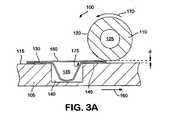
医薬製剤は、しばしばユーザーがそこから医薬製剤を利用できるような容器に詰められる。例えば、1回分の投与量またはその一部を、通常ブリスターまたはブリスターパックと呼ばれる多層包装の層間に貯蔵することができる。一般に下部層に空洞が形成され、医薬製剤がこの空洞内に入れられ、例えば層を加熱しかつ/または圧縮することによって上部層を下部層に封着させて、医薬製剤を空洞内に固定する。空洞は、層を分離することによって、最上層からまたは最上層の弱い部分から医薬製剤を押すことによって、または器具で層のうちの1つに穴を開けることによって、ユーザーが空洞にアクセスできるように設計することができる。 Pharmaceutical formulations are often packaged in a container from which the user can access the pharmaceutical formulation. For example, a single dose or a portion thereof can be stored between layers of a multi-layer package, commonly referred to as a blister or blister pack. A cavity is generally formed in the lower layer, and the pharmaceutical formulation is placed in this cavity, and the upper layer is sealed to the lower layer, for example, by heating and / or compressing the layer, to secure the pharmaceutical formulation in the cavity . The cavity can be accessed by the user by separating the layers, by pushing the pharmaceutical formulation from the top layer or from the weakest part of the top layer, or by piercing one of the layers with an instrument. Can be designed to
医薬製剤によっては従来のブリスター式の包装で効果的に包装するのが難しいことがしばしばある。例えば、包装の層をヒートシールする場合、層を封着させるために熱を加えると空洞の温度も上げるので、空洞内の医薬製剤も加熱し、その特性に影響を及ぼす場合がある。さらに、従来の密封法は、医薬製剤の環境劣化を防ぐのに充分な保護シールを形成しないことが多い。 Some pharmaceutical formulations are often difficult to package effectively with conventional blister packaging. For example, when heat sealing a layer of a package, applying heat to seal the layer also raises the temperature of the cavity, which may heat the pharmaceutical formulation in the cavity and affect its properties. Furthermore, conventional sealing methods often do not form a protective seal sufficient to prevent environmental degradation of pharmaceutical formulations.
従って、改良された方法により多層包装で医薬製剤を包装できることが望ましい。さらに、医薬製剤の特性に実質的に影響を及ぼすことなく多層包装で医薬製剤を包装することが望ましい。また、医薬製剤をよりよく保護しかつ/またはシールをより一貫したものにするために多層包装の密封を改良することが望ましい。 Therefore, it would be desirable to be able to package pharmaceutical formulations in multilayer packaging by an improved method. Furthermore, it is desirable to package the pharmaceutical formulation in a multilayer packaging without substantially affecting the properties of the pharmaceutical formulation. It is also desirable to improve the sealing of the multi-layer package in order to better protect the pharmaceutical formulation and / or make the seal more consistent.
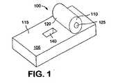
本発明は、上記のニーズを満たすものである。本発明の1つの態様においては、医薬包装を改良するために多層包装の層を加熱ローラーによって封着させる。 The present invention satisfies the above needs. In one embodiment of the invention, the layers of the multi-layer package are sealed by a heated roller to improve the pharmaceutical package.
本発明の別の形態においては、医薬製剤を入れるのに適する1つまたはそれ以上の空洞を備える第二の層に第一の層を封着させるための装置は、加熱素子を備えるローラー、及び第一の層及び第二の層を支持するのに適する表面を備え、前記表面はローラーに対して相対的に移動可能であり、これによって、1つまたはそれ以上の空洞内に医薬製剤を納めるためにローラーによって接触させると第一の層を第二の層にヒートシールさせても良い。 In another aspect of the invention, an apparatus for sealing a first layer to a second layer comprising one or more cavities suitable for containing a pharmaceutical formulation comprises: a roller comprising a heating element; and A surface suitable for supporting the first layer and the second layer, said surface being movable relative to the roller, thereby accommodating the pharmaceutical formulation in one or more cavities; For this purpose, the first layer may be heat sealed to the second layer when contacted by a roller.
本発明の別の形態においては、医薬製剤を入れるのに適する1つまたはそれ以上の空洞を備える第二の層に第一の層を封着させるための装置は、加熱素子を備えるローラー、及び第二の層を支持するのに適する表面を備え、この装置において、前記表面の少なくとも一部が実質的に平らであり、それによって、1つまたはそれ以上の空洞内に医薬製剤を納めるためにローラーによって接触させると第一の層を第二の層にヒートシールさせても良い。 In another aspect of the invention, an apparatus for sealing a first layer to a second layer comprising one or more cavities suitable for containing a pharmaceutical formulation comprises: a roller comprising a heating element; and A surface suitable for supporting the second layer, wherein the device is such that at least a portion of the surface is substantially flat, thereby accommodating the pharmaceutical formulation in one or more cavities; When contacted by a roller, the first layer may be heat sealed to the second layer.
本発明の別の形態においては、包装を密封する方法は、ある表面に第一の層及び医薬製剤を納める1つまたはそれ以上の空洞を備える第二の層を提供する手順と、加熱ローラーでこれらの層を一緒に圧縮する手順と、及び前記表面に対して相対的に加熱ローラーを移動させる手順とを具備し、それによって、1つまたはそれ以上の空洞内に医薬製剤を納めるためにローラーによって接触させると第一の層を第二の層にヒートシールさせても良い。 In another aspect of the invention, a method for sealing a package comprises: providing a second layer comprising one or more cavities containing a first layer and a pharmaceutical formulation on a surface; A roller for compressing the layers together and moving a heated roller relative to the surface to thereby place the pharmaceutical formulation in one or more cavities The first layer may be heat sealed to the second layer.
本発明の別の形態においては、医薬品包装は、ある表面に第一の層及び医薬製剤を入れる1つまたはそれ以上の空洞を備える第二の層を提供する手順と、加熱ローラーでこれらの層を一緒に圧迫する手順と、更に前記表面に対して相対的に加熱ローラーを移動させる手順とを具備する方法により製作されており、それによって、1つまたはそれ以上の空洞内に医薬製剤を納めるためにローラーによって接触させると、第一の層を第二の層にヒートシールすることができる。 In another form of the invention, the pharmaceutical packaging comprises a procedure for providing a second layer comprising one or more cavities for placing the first layer and the pharmaceutical formulation on a surface, and these layers with a heated roller. And a step of moving a heated roller relative to the surface, thereby placing the pharmaceutical formulation in one or more cavities Thus, when contacted by a roller, the first layer can be heat sealed to the second layer.
本発明の上記の特徴、態様及び利点は、以下の説明、付属クレーム及び本発明の例示的特徴を示す添付図面を参照することによってより良く理解できる。ただし、特徴の各々は特定の図面においてのみでなく本発明全般に使用することができ、本発明はこれらの特徴の組み合わせを含むものとする。 The above features, aspects and advantages of the present invention may be better understood with reference to the following description, appended claims and accompanying drawings which illustrate exemplary features of the invention. However, each of the features can be used throughout the present invention, not just in a particular drawing, and the present invention is intended to include combinations of these features.
本発明は、包装の密封に関するものである。この工程は多層包装で医薬製剤を包装するという状況で示されているが、本発明は、他の工程において使用することができ、本明細書において示される例に限定されるべきではない。 The present invention relates to sealing a package. Although this process is illustrated in the context of packaging pharmaceutical formulations in multi-layer packaging, the present invention can be used in other processes and should not be limited to the examples shown herein.
本発明に従った密封装置100が略図的に図1に示されている。この密封装置は、プラットフォーム105及びローラー110を備える。プラットフォーム105は、密封対象物を支持する表面115を有する。ローラー110は、ローラー110が表面115の少なくとも一部を通り過ぎるように表面115に対して相対的に移動可能である。ローラー110は、表面115上の対象物の少なくとも一部の上を転がるローラー表面120を有する。1つの実施の形態においては、ローラー110は、ローラー表面120を目標の温度に加熱することができる加熱素子125を含む。加熱素子125は、図1に示される通りローラー110内に配置することができる。これとは別に、加熱素子125をローラー110から分離させるが、ローラー表面120を加熱することができるようにローラー110と連絡させても良い。 A
1つの実施の形態においては、密封装置100は、ブリスターなど多層包装内に医薬製剤を密封するのに適する。例えば、密封装置100は、層間に医薬製剤を入れて複数の層を相互に封着させることができる。密封工程の例が図2Aから2Cまでに示されている。多層包装の下部層130はプラットフォーム表面115上に置かれる。図に示される実施の形態においては、下部層130は、医薬製剤を入れることができる空洞135を備える。縁部145を表面115に乗せたまま、空洞135は、表面115の凹部140内に配置される。下部層130を表面115に配置したまま、空洞135をプラットフォーム105上で形成し、かつ/または医薬製剤を空洞135に注入することができる。これとは別に、事前に形成された空洞135に医薬製剤を事前に充填して下部層130を表面115に配置することができる。次にまたは事前に、図2Bに示される通り上部層150を下部層130の上に配置する。これらの層がプラットフォーム105上に配置されたら、ローラー表面120を目標の温度まで加熱して、ローラー110に対して相対的にプラットフォーム表面115を移動させて、ローラー110が層の上を通過するようにする。層の加熱及び/または圧縮により、層を相互に封着させ、医薬製剤を密封された多層包装155内に固定する。 In one embodiment, the
密封工程は、さらにそれぞれ図2Bの線A-A及び図2Cの線B-Bに沿って見た断面図を示す3A及び3Bにおいても示されている。図3Aにおいては、下部層130は、プラットフォーム表面115上に配置され、医薬製剤が充填された空洞135が凹部140内に配置される。上部層150は、下部層130の上に配置される。上部層150と下部層130の間には、加熱及び/または圧縮されると上部層150と下部層130との間にシールを形成させるシール材がある。層を封着させるために、プラットフォーム105は、矢印160に示される方向にローラー110に対して相対的に移動する。これらの層がローラー110とプラットフォーム105の間を通過すると、シール165が、例えば下部層の130の縁部145と縁部145と接する上部層150の部分との間に形成されることによって、層間に形成される。図に示される構成の代わりに、凹部140を空洞135の輪郭にもっと似せて形成することができる。 The sealing process is further illustrated in 3A and 3B, which show cross-sectional views taken along line AA in FIG. 2B and line BB in FIG. 2C, respectively. In FIG. 3A, the
ローラー110は、上部層150と下部層130との間に圧力を加えても良い。例えば、1つの実施の形態においては、ローラー110とプラットフォーム115との間の間隔dは、下部層130と上部層150とを組み合わせた結合厚みより小さいので、ローラー110と表面115の間を通過するときこれらの層は圧縮される。例えば、距離dは層の結合厚みの約0%から約100%とすることができるが、約30%から約98%までがより望ましく、約60%から約95%までが最も望ましい。別の実施の形態においては、ローラー110はプラットフォーム表面115上に乗り、ローラー110の質量が層を圧縮するのに役立っても良い。さらに、ローラー110は、矢印170の方向に回転するように設計されても良い。1つの実施の形態においては、ローラー110を回転させるために、ロータリー・モーターなどのアクチュエータを具備しても良い。モーターは、ローラー110に対して相対的な表面115の移動に応じてローラー110の回転を制御しても良い。これとは別に、モーターは、ローラー110を並進させるようにローラー110を回転させても良い。別の実施の形態においては、ローラー110は、表面115の移動及び対象物及び/またはプラットフォームの摩擦がローラー110を回転させるように自由に回転する。さらに別の実施の形態においては、プラットフォーム105の移動がローラー110を回転させるようにまたはローラー110の回転がプラットフォーム105を移動させるように、ギアが具備されても良い。特定の1つの実施の形態においては、表面速度は基準グラウンドに対して実質的にゼロである。 The
ローラー110は、密封工程を容易にするために層に熱を与えるための加熱素子125を備えても良い。例えば、図3A及び3Bに示される実施の形態においては、加熱素子125は、ローラー110内部に配置されても良い。加熱素子125は、主にローラー110全体に熱を伝導することによってローラー表面120を加熱するのに役立つ。層がローラー110とプラットフォーム105との間を通過するとき、加熱された表面120が層に接触する。従って、ローラー表面120を、使用される移動速度に合わせて充分な熱を与えるために予め決められた温度に加熱することができる。加熱素子125は、ローラーの回転軸に沿って伸びる円筒形の穴内に配置される円筒形の抵抗ヒーター・カートリッジなどの発熱素子を含むことができる。ローラー110は、ローラー表面120全体をほぼ均等な温度プロフィルとするために、金属など高熱伝導率の材料を具備しても良い。ローラー110は、適切であればどのような半径のものでもよい。ローラーの半径は、密封工程中のローラー110の回転が約360度未満であるように選択されることが好ましく、温度安定性のために約270度未満であることがより好ましい。別の実施の形態においては、加熱素子は、ローラー110外部にある。例えば、加熱素子が例えば対流及び/または輻射によってローラー表面120の外面に熱を伝導するように、加熱素子を配置しても良い。 The
シール材は上部層150と下部層130との間に配置され、熱及び/または圧縮が間に挟まれる層に加えられるとき上部層150を下部層130に封着させることができる材料を含む。例えば、1つの実施の形態においては、シール材は、ラッカーまたはポリメタクリル酸メチル(PMMA)など熱活性化シーラーの層を含む。熱活性化シーラーは、上部層150の下面175に配置することができる。少なくとも約140℃、多くの場合少なくとも約160℃など充分な温度に加熱されると、熱活性化シーラーは状態を変えるので、冷却されると上部層150は下部層130に封着する。これとは別に、熱活性化シーラーを下部層130の上面に配置しても良く、あるいは上部層150と下部層130との間に配置される別個のシートとしても良い。別の実施の形態においては、熱活性化シーラーを上部層150及び/または下部層130の材料としても良い。この実施の形態においては、冷却したとき層が相互に融着しても良いように、層の間の材料が溶融するのに充分な熱が加えられても良い。ローラー110は、シーラーをより均等に配分するため及び/または上部層150を下部層130に結合させるのを助けるために密封工程中熱活性化シーラーに圧縮を加えても良い。これとは別に、シール材は、活性化するために熱を必要としない接着剤または結合剤を具備してもよい。この実施の形態の場合、ローラー110は、層を圧縮して層をより良く封着させるように使用されても良い。 The sealant is disposed between the
本発明の密封装置110は、多層包装を有利に密封することが判明している。例えば、プラットフォーム表面115に対して相対的に移動可能なローラー110を使用することは、均等にまたはほぼ均等に上部層150と接する平らな圧縮および/または加熱部材の使用に比べて有利である。図3Bにおいて分かる通り、ローラー表面120は上部層150の一部のみに接する。接触部分cは、ローラー表面120に接触する上部層150の部分である。この接触部分cの長さは、上部層150の長さより小さい。このように接触部分を短くすることによって、圧縮される表面の割合はより大きくなり、シール材は密封エリア全体により均等に分配される。その結果、材料の不連続性または不完全性の影響が最小限に抑えられる。 The
さらに、高温は一部の医薬製剤に悪影響を及ぼす可能性があることが確認されている。例えば、医薬製剤によっては約100℃またはそれ以上の温度にさらされると劣化し、また他の医薬製剤は約80℃またはそれ以上の温度にさらされると少なくとも部分的に変質する。高温は特にエーロゾル化される粉末医薬製剤にとって望ましくないことが判明している。このような医薬製剤においては、温度が上がると凝塊形成を引き起こして目標のエーロゾル性能より低くなったり、形態的劣化を引き起こしたりする可能性がある。さらに、過度の熱は、他のタイプの医薬製剤を形態的に変化させる可能性がある。加熱素子を備えるローラー110を使用するなどによる封着対象の層の一部の局部的加熱は、密封工程中の空洞135の温度を予期しないほど低下させることによって、均等加熱工程に比べて密封工程中の空洞135内の医薬製剤が受ける温度を下げることが判明している。さらに、本発明の密封装置100を使用する場合、空洞135の温度を著しく上げることなく、より高いシール温度を使用できることが思いがけなく判明した。 Furthermore, it has been identified that high temperatures can adversely affect some pharmaceutical formulations. For example, some pharmaceutical formulations degrade when exposed to temperatures of about 100 ° C. or higher, and other pharmaceutical formulations are at least partially altered when exposed to temperatures of about 80 ° C. or higher. High temperatures have been found to be undesirable, especially for powdered pharmaceutical formulations that are aerosolized. In such pharmaceutical formulations, elevated temperatures can cause agglomeration, resulting in lower than target aerosol performance or morphological degradation. Furthermore, excessive heat can morphologically change other types of pharmaceutical formulations. Local heating of a portion of the layer to be sealed, such as by using a
1つの実施の形態においては、密封装置100は、過度の湿度にさらされると劣化及び/またはエーロゾル性能低下を引き起こしやすい医薬製剤の周りの多層包装を密封するために使用することができる。例えば、多層包装は、防湿材料を含む1つまたはそれ以上の層を含んでも良い。防湿材料は、アルミニウムなど1つまたはそれ以上の金属及び/またはポリアミド、ポリ塩化ビニルなどその他の防湿材料を含む。防湿材は、さらなる防湿のために医薬製剤の上下に配置されても良い。たとえば、図4の実施の形態に示される通り、多層包装155は金属含有層180から成る下部層130及び金属含有層から成る上部層150を含んでも良い。金属含有層180、185は、大量の湿気が通り抜けるのを実質的に防ぐのに充分な厚みとしても良い。例えば、金属含有層180、185は、約10μmから約100μmまでとしても良く、約20μmから約80μmまでがより好ましい。下部層130と上部層150は、約1μmから約20μmまでのラッカー層などシール材の層によって封着する。空洞135内には、エーロゾル化できる乾燥粉末状の医薬製剤などの医薬製剤が入っている。これとは別に、医薬製剤はカプセル、錠剤、エリキシル剤状などにすることができる。多層包装155の下部層130及び/または上部層150は、任意に、層の封着または成形性を改良するのに役立つ付加的材料を選択可能に含んでも良い。例えば、図5は、医薬製剤の防湿包装を行うのに役立つ特定の実施の形態の多層包装155を示している。この実施の形態においては、下部層130は、ポリ塩化ビニルなど高分子材料を含み約60μmの厚みを有する第一の層200と、ナイロンなどポリアミドを含み約25μmの厚みを有する第二の層205と、アルミニウムなど金属を含み約60μmの厚みを有する第三の層210と、及びポリ塩化ビニルなど高分子材料を含み約60μmの厚みを有する第四の層215とを具備する。上部層150は、アルミニウムなど金属を含み約25μmの厚みを有する第一の層220と、ラッカーなどシール材を含み約6μmの厚みを有する第二の層225とを具備する。 In one embodiment, the
図4及び5の包装によって与えられる防湿性は、上部層150を下部層130に封着させるために本発明の密封装置100を使用することによって改良される。従来の密封法の場合空洞内の医薬製剤が約15日から約20日までの間湿気から充分に保護されることが確認されている。しかし、本発明の密封装置110を使用すると、防湿性は著しく改良される。改良の正確なメカニズムは不明であるが、以下のことのうち1つまたはそれ以上が防湿性増加に寄与していると考えられる。1)局部的な圧縮及びローリングがシール内に閉じ込められる空気の量を減少する。2)異なる膨脹率の影響が目立たない。3)局部的熱及び圧力を受ける高分子材料の再配向が改良される。4)ローラーによって与えられる高分子の圧縮、流動及び回復の部分的結合がボイドを残す。 The moisture resistance provided by the packaging of FIGS. 4 and 5 is improved by using the
さらに、本発明の密封装置100を使用することによって、空洞135内の医薬製剤の熱劣化が減少することが分かっている。図6Aに示される通り、加熱素子125を備えるローラー110の使用は、多層包装155の長さに沿った特定の部分に加熱を限定する。多層包装155の温度は、接触部分cにおいて最高であり、直接ローラー100と接しない部分では急激に低下する。1つの実施の形態においては、長さ約10mm(約0.4インチ)から約12.5mm(約0.5インチ)の空洞の場合、接触部分は約2.5mm(約0.1)から約25.5mm(1.0インチ)までであっても良く、約1.3mm(約0.05インチ)から約10mm(約0.4インチ)までがより好ましく、約20mm(約0.8インチ)から約5mm(約0.20インチ)までがより好ましく、約3.0mm(約0.12インチ)が最も好ましい。空洞のサイズが異なれば、それに応じて接触部分を変えても良い。図6Bに示される通り、多層包装の縁部145に加えられる熱250は空洞135に伝えられ、ここで医薬製剤は熱にさらされる。この熱の伝導は、層130、150のうち1つまたはそれ以上が金属含有層である場合に特に顕著である。密封装置100を使って局部的に加熱することによって、熱の伝導が減少する。試験中、多層包装155の4つの点、すなわち空洞135から離れた縁部の点T1、縁部145に近接する空洞135内の点T2、医薬製剤の高さより低い空洞135内の点T3、及び空洞135の最も深い部分の点T4で密封工程中の温度が測定された。半径約50mm(約2インチ)のローラー110の温度は180℃に設定され、長さ約11.5mm(約0.45インチ)及び深さ約2.5mm(約0.1インチ)の空洞を有していて図5に示される、多層包装を密封するために約20mm/秒(約0.8インチ/秒)の速度160でプラットフォーム105及びローラー110を並進させた。その結果得られた密封工程中の4点における温度曲線は図6Cに示される通りである。図から分かる通り、T1は、ローラー110と接触するとき最高約140℃に達するが、ローラー110がこの点を通り越して進むにつれて、熱は急速に分散する。局部的な比較的高い温度は層全体に急速に拡散して、平均温度は低い値となる。縁部145に沿った点での加熱時間が短縮される結果、空洞135に伝導される温度は低くなり、空洞内における温度T2、T3、T4は約65℃より下に維持され、空洞135内の医薬製剤を著しく変質しない。Furthermore, it has been found that using the
温度プロフィルのこの減少について、本発明の密封装置100によって与えられる局部加熱を使用する場合の密封中の温度を、多層包装155の上面を均等に加熱する装置を使用する場合の密封中の温度と比較する、図7Aから7Dまでに示されている。均等加熱工程は、約0.6秒間多層包装155に接触する約170℃に加熱されたシーリング・プレートを使って行われた。図7Aから分かる通り、本発明に従った工程を使用した場合T1において到達した最高温度は、均等加熱工程を使用した場合のT1における温度に比べて著しくより低く、本発明の工程を使用した場合高温に維持される時間が著しく短い。最高温度が低く時間が短くなるため、空洞135に伝導される熱は少なくなり、その結果空洞135内の温度が低くなる。例えば、図7Bに示される通り、均等加熱工程の場合のT2における温度は、密封工程中のかなりの時間において、100℃を上回る。約100℃の温度は一部の医薬製剤にとって有害である。さらに図7C及び7Dに示される通り、空洞内のさらに深い点の温度も、均等加熱の場合100℃に近づくまたはこれに達する。これに対して、本発明の工程を使用する局部加熱は、空洞温度を約65℃より低くするので、これより高い温度で熱損傷を受ける医薬製剤を包装することを可能にする。さらに、空洞135内の医薬製剤の熱損傷は、医薬製剤の上面と上部層150との間に空間を設けることによってさらに減少させることができる。こうすることによって熱が上部層150から医薬製剤に直接伝わるのを防ぐ。For this reduction in temperature profile, the temperature during sealing when using the local heating provided by the
多層包装155の密封の品質は、本発明の密封装置100を使用することによって予想以上に改善される。例えば、図8は、上述の均等加熱工程に従って密封された4つのサンプル多層包装と一緒に本発明の工程270に従って密封された多層包装のシール強さのインストロン(Instron)試験結果のグラフを示している。本発明の工程においてローラー110は均等加熱工程のシーリング・プレートより低い温度に維持され、縁部分145に沿って達した最高温度は本発明の工程の場合の方が低かったが、シールの強さはより大きい。従って、本発明の工程の場合、シールが改良されながら、同時に包装される医薬製剤の望ましくない変質が防止される。本発明の予想外の付加的な成果は、ローラー温度及び接触時間(ローラーの移動速度で接触部分の長さCを割った値)の関数として空洞ピーク温度の様子を示す図9に示されている。図から分かる通り、空洞ピーク温度はローラー温度より接触時間の影響をより大きく受ける。従って、接触時間が充分小さく維持されれば、空洞135を不利に加熱することなく非常に高いローラー温度を採用することができる。また、図9は、接触時間はローラー温度より制御しやすい変数なのでこの工程が予想外に制御しやすいことを立証している。 The sealing quality of the
密封装置100の特定の実施の形態が図10に示されている。この実施の形態においては、プラットフォーム105及びローラー110を支持するため及びプラットフォーム105とローラー110との間に移動及び/または回転を与えるために台300が配備される。この実施の形態においては、プラットフォーム105は台300の上面305に取り外し可能に挿入できる。プラットフォーム105を台300上で適切に位置合わせするために、上面にプラットフォーム105を受ける1つまたはそれ以上の位置合わせ部材310がある。台300は、また、1つまたはそれ以上のガイドレール315を備える。ガイドレールは、ローラー・キャリア320が台300の上面305に対して相対的に移動できるようにローラー・キャリア320を支持する。ローラー・キャリア320は、1つまたはそれ以上のローラー支持部材325を備える。図に示される実施の形態においては、2つのローラー支持部材325は、ローラー310の延長部335を回転可能に受け入れるための通り穴330を有する。ローラー・キャリア320は、また、ローラー110の底部が延びることができる開口部340を備えても良い。1つの実施の形態においては、開口部340のサイズ及び厚みは、実質的にローラー表面の接触エリアcのみがローラー・キャリア320のサイド・パネルより下に伸びるように選択される。このように、サイド・パネルは、加熱を接触エリアcに限定するのを助ける熱シールドとして役立つ。従って、多層包装がプラットフォーム105の表面115上に配置され、プラットフォーム105が台300上に配置されると、ローラー表面120は上述の通り多層包装と接触して、層を封着させる。この接触は、ローラー110を台300の上面305よりまたはプラットフォーム105の表面115より予め決められた距離だけ上に配置することによって可能になる。これとは別に、プラットフォーム105をローラー110に向かって付勢するかまたはローラー110を台300に向かって付勢するばねなどのメカニズムを配備することによって接触させても良い。ばねは、予め決められた圧力の大きさが包装に与えられるようなサイズまたは形状としても良い。これとは別に、ローラー110のサイズ及び/または重量を選択することによって圧力の大きさを制御しても良い。別の実施の形態においては、プラットフォーム105がその縦軸に平行の軸の周りを旋回できるように、プラットフォーム105を台に軸旋回可能に接続しても良い。このようにして、ローラー110とプラットフォーム105の間の不整合を調整しても良い。これとは別に、ローラー110を旋回可能としても良い。 A particular embodiment of the
プラットフォーム105は、1つまたはそれ以上の凹部140を有する表面115を有しても良い。例えば、図10の実施の形態においては、空洞135が凹部内に配置されるように空洞135が形成されている下部層130を表面115上に配置しても良い。これとは別に、冷間成形などにより空洞135を成形するための型として凹部が使用されても良い。別の実施の形態においては、図11Aに示される通り、プラットフォームに複数の凹部140が配備される。この実施の形態においては、ローラー110は、プラットフォーム105上に配置される2つ以上の多層包装に接触するのに充分な幅を有する。別の実施の形態においては、図11Bに示される通り、凹部140の配列が具備されても良い。この実施の形態においては、プラットフォーム105に沿ったローラー110の移動は、プラットフォーム105上に配置される多層包装の配列に接触するのに充分な長さに達する。別の実施の形態においては、プラットフォーム105は凹部の配列を備えても良く、ローラー110は、配列の一部のみを密封するように形成されても良い。残りの凹部は、追加の1つまたはそれ以上のローラーによって、または第一のローラーをさらに1回または複数回配列を通過させることによって、密封することができる。プラットフォーム105は、ロボット型メカニズムなどのメカニズムによって台300上に配置するか、手で配置されても良い。これとは別に、プラットフォーム105を台300に固定しても良く、多層包装または多層包装の配列をメカニズムによってまたは手でプラットフォーム105上に配置しても良い。表面115は、ローラー110が多層包装に予め決められた大きさの圧力を与えるように選択された材料で作られても良い。例えば、表面は、約10から約100までのデュロメーター硬さを有する材料で作ることができる。1つの実施の形態においては、表面は、ヌムール(Nemours)のE. I. Dupont社から入手できるVitonTMなど約70のデュロメーター硬さを有するフルオロエラストマーを具備する。VitonTM表面は、優れた熱抵抗を示す点でも有利である。1つの実施の形態においては、表面115は、位置合わせを容易にしかつ相対的動きをより正確に制御するために実質的に平らであっても良い。
ローラー110とプラットフォーム105の相対的な回転及び/または移動は、例えば図12及び13に示される通り、コントローラ350によって制御されても良い。図12に示される実施の形態においては、例えば延長部335を受け入れてこれとかみ合うことによってローラー110と回転可能にかみ合うように、ローラー支持部材325にロータリー・モーター360が配備される。モーター360は、延長部335を回転させることができるので、これによってローラー110を回転させることができる。コントローラ350は、モーター360と連絡しており、例えば予め決められた回転速度でローラーを回転させることによって、ローラー110の動作を制御するのに適する。このようにして、ローラー110の回転は、ローラー・キャリア320をガイドレール315に沿ってスライドさせることによってプラットフォーム105に対して相対的にローラーを移動させても良い。別の実施の形態においては、ローラー110の移動は、図13に示される通りローラー・キャリア320をガイドレール315に沿ってスライドさせるモーター370によって行われても良い。これとは別に、ローラー・キャリア320に直接作用するリニア・モーターを配備されても良い。図に示される実施の形態においては、モーター370は、例えばそれぞれの部材に歯と溝を配備することによって、駆動軸375の回転を突条380の移動に変換するようにローラー・キャリア320から伸びる突条380にかみ合う駆動軸375を回転させるロータリー・モーターである。この実施の形態においては、ローラー・キャリア320の移動及びその結果生じるローラー表面120と多層包装との間の摩擦により、ローラー110の回転を生じるように、ローラー110はローラー支持材325内部で自由に回転可能であっても良い。コントローラ350は、移動速度を制御するために図13の実施の形態のモーター370を制御することができる。別の実施の形態においては、ローラー110の回転及びプラットフォーム105に対して相対的なローラー110の移動の両方が制御されても良い。この実施の形態は、コンポーネント及び/または包装に与えられる応力が小さくなる点が有利である。これとは別に、ローラー110は手によりプラットフォーム105に対して相対的に移動させられても良い。市販の多様なモーターが使用に適している。このようなモーターには、ステッピング・モーター、サーボ・モーター、空気圧アクチュエータなどを具備しても良い。さらに、モーターは、工程を付加的に制御するために、ローラー110またはローラー・キャリア320の位置を感知することによってコントローラ350に入力を与えることもできる。この種のセンサにはコード化ホイール・トランスデューサ、ポテンショメーターなどが含まれる。ハイブリッドまたは双方向トランスデューサは、入力及び出力機能を兼ね備えることが多い。さらに、温度センサが配備されても良い。温度センサは、ローラー表面120またはその他の表面の温度を検出するのに適するものであっても良い。温度センサはコントローラ350と連絡しても良く、コントローラは検出される温度に応じて密封工程を制御しても良い。 The relative rotation and / or movement of the
コントローラ350は、上述の通り密封装置100の動作を制御しても良い。コントローラ350は本発明の説明を単純化するために例として単一のコントローラ装置として示されているが、コントローラ350は相互に接続できる複数のコントローラ装置または密封装置の異なるコンポーネントに接続されても良い複数のコントローラ装置であっても良い。 The
1つの実施の形態においては、コントローラ350は、密封装置100を作動または制御するのに適する集積回路を備える電気回路を含めて電子ハードウェアを備える。一般的に言って、コントローラ350は、データ入力を受信し、アルゴリズムを実行し、有益な出力信号を生成するのに適し、1つまたはそれ以上のセンサ及びその他の装置コンポーネントからのデータ信号を検出し密封装置100の工程を監視または制御するために使用されても良い。ただし、コントローラ100は、上記のタスクのうち1つだけを実施しても良い。1つの実施の形態においては、コントローラ350は、(1)周辺制御コンポーネントと一緒にメモリ・システムに相互接続される中央処理装置(CPU)を備えるコンピュータ、(2)密封装置100の特定コンポーネントを作動するまたは特定工程を作動する特定用途向け集積回路(ASIC)、及び(3)適切な支持回路を伴う1つまたはそれ以上のコントローラ・インターフェイス・ボード、のうち1つまたはそれ以上を備えることができる。典型的なCPUとしては、PowerPCTM、PentiumTM、及びその他のプロセッサがある。ASICは、密封装置100からのデータ及びその他の情報の検索及び/または特定の装置コンポーネントの作動など、特定のタスクに合わせて設計され事前にプログラムされる。典型的な支持回路としては、例えばコプロセッサ、クロック回路、キャッシュ、電源及びCPUと連絡するその他の周知のコンポーネントがある。例えば、CPUは、ランダム・アクセス・メモリ(RAM)、読み出し専用メモリ(ROM)及び従来技術において周知のその他の記憶装置と一緒に動作することが多い。RAMは、工程実施中本発明のソフトウェア実行を記憶するために使用できる。本発明のプログラム及びサブルーチンは、一般に大容量記憶装置に記憶され、CPUによって実行されるときRAMの一時記憶装置に呼び出される。In one embodiment, the
本発明のソフトウェア実行及びコンピュータ・プログラム・コード積は、EPROMなどの記憶装置に記憶され、実行中コントローラ350によってRAMに呼び出されても良い。コンピュータ・プログラム・コードは、例えばアセンブリ言語C、C”、Pascalまたはネイティブ・アセンブリなど従来のコンピュータ読み取り可能プログラミング言語で書き込まれても良い。適切なプログラム・コードは、従来のテキスト・エディタを使って単一のファイルまたは複数のファイルに入力され、コンピュータ・システムのメモリなどコンピュータに利用可能な媒体に記憶されるかまたはこれに組み込まれる。入力されたコード・テキストが高水準言語である場合、コードは、プリコンパイルされたウィンドウズ・ライブラリ・ルーチンのオブジェクト・コードとリンクされるコンパイラ・コードにコンパイルされる。リンクされコンパイルされたオブジェクト・コードを実行するためにシステム・ユーザーはオブジェクト・コードを呼び出して、コンピュータ・システムはコンピュータ・プログラムにおいて特定されるタスクを実施するためにコードをメモリにロードする。 The software execution and computer program code products of the present invention may be stored in a storage device such as an EPROM and recalled to the RAM by the executing
1つの実施の形態においては、コントローラ350は、エーロゾル化装置100上またはその中に収納するのに充分に小さいサイズ及び電力消費のマイクロプロセッサまたはASICを備えても良い。例えば、ローカル・マイクロプロセッサとして使用するのに適するマイクロプロセッサとしては、Motorola社のMC68HC711E9、Microchip社のPIC16C74、及びIntel Corporationの82930AXがある。このマイクロプロセッサは1つのマイクロプロセッサ・チップ、複数のプロセッサ及び/またはコプロセッサ・チップ、及び/またはデジタル・シグナル・プロセッサ(DSP)機能を含むことができる。 In one embodiment, the
1つの実施の形態においては、密封装置100は、多層包装の空洞135内に乾燥粉末医薬製剤を密封するのに適する。1つの特定の実施の形態においては、乾燥粉末医薬製剤の少なくとも一部は包装の下部層130に直接接触するが、この場合には下部層130が過剰な温度に達しないようにすることが重要な場合がある。これとは別に、乾燥粉末医薬製剤と包装の下部層130との間にカプセル容器などの材料が配備されても良い。この場合にも、この材料を通じて医薬製剤に熱が伝導される可能性があるので、空洞内の過剰な熱を防止する必要であっても良い。 In one embodiment, the
空洞135は、ユーザーの吸入用にエーロゾル化できる形で医薬製剤を納めても良い。。例えば、粉末状の場合、米国特許第5,785,049号、米国特許第5,415,162号及び米国特許出願第09/583,312号において説明される通り、粉末をまず密封包装に貯蔵しても良く、粉末をエーロゾル化する前にこれを開封することができる。これとは別に、米国特許第4,995,385号、米国特許第3,991,761号、米国特許第6,230,707号及びPCT公告第WO97/27892号において説明される通り、粉末をカプセルに入れても良い。カプセルは、カプセルをエーロゾル化装置に挿入する前、挿入中または挿入後に開けることができる。原末(バルク)、ブリスター、カプセルなどの形の粉末は、米国特許第5,458,135号、米国特許第5,785,049号及び米国特許第6,257,233号において説明される通り圧縮空気、または2000年4月24日に提出された「エーロゾル化の装置及び方法」と題する米国特許出願第09/556,262号及びPCT公告第WO00/72904号において説明される推進剤など活性な素子によってエーロゾル化することができる。これとは別に、例えば上記の米国特許出願第09/583,312号及び米国特許第4,995,385号において説明される通りユーザーの吸入に反応して粉末はエーロゾル化されても良い。上記の参照文献は全てその全体が参照により本明細書に組み込まれる。 The
好適な実施の形態においては、本発明は、医薬製剤をエーロゾル化し医薬製剤をユーザーの肺に送達するためのシステム及び方法を提供する。医薬製剤は、粉末薬剤、水溶液または懸濁液及びこれに類するものを含めても良く、医薬品として活性な作用物質を含んでも良い。 In a preferred embodiment, the present invention provides systems and methods for aerosolizing a pharmaceutical formulation and delivering the pharmaceutical formulation to a user's lungs. Pharmaceutical formulations may include powdered drugs, aqueous solutions or suspensions and the like, and may include pharmaceutically active agents.
本明細書において説明される前記活性な作用物質は、薬理効果多くの場合有益な薬理効果を与える薬剤、薬物、化合物、合成物またはその混合物を含む。この中には、食品、栄養補助食品、栄養素、薬物、ワクチン、ビタミン、及びその他の有益な物質が含まれる。本明細書において使用される場合、この用語は、さらに、患者に局部的または全身的効果を生じる生理学的または薬理学的な医薬品として活性な作用物質を含む。本明細書において説明される医薬製剤に組み込める前記活性な作用物質は、末梢神経、アドレナリン受容体、コリン作動性受容体、骨格筋、心臓血管系、平滑筋、血管系、神経効果器接合部、シノプティック部、内分泌及びホルモン系、免疫系、生殖器系、骨格系、オータコイド系、消化器及び排出系、ヒスタミン系及び中枢神経系に作用する薬物を含める(ただし、これに限定されない)無機または有機化合物である。適切な前記活性な作用物質は、例えば催眠薬及び鎮静剤、精神賦活剤、トランキライザー、呼吸薬、抗痙攣薬、筋弛緩剤、抗パーキンソン病薬(ドーパミン拮抗薬)、鎮痛薬、抗炎症薬、抗不安薬(緩和安定剤)、食欲抑制剤、抗偏頭痛薬、筋肉収縮薬、抗感染薬(抗生物質、抗ウィルス性、抗真菌性、ワクチン)抗関節炎薬、抗マラリア薬、鎮吐薬、抗癲癇薬、気管支拡張薬、サイトカイン、成長因子、抗がん剤、抗血栓薬、抗高血圧薬、心血管薬、抗不整脈薬、酸化防止剤、抗喘息薬、避妊薬を含むホルモン剤、交感神経作用薬、利尿剤、脂質調整薬、抗男性ホルモン剤、駆虫剤、抗凝固薬、新生物、抗腫瘍薬、血糖降下薬、栄養剤及び栄養補助剤、成長補助剤、抗腸炎薬、ワクチン、抗体、診断薬及び対照薬から選ぶことができる。吸入によって投与される場合、前記活性な作用物質は、局部的にまたは全身的に作用しても良い。 The active agents described herein include pharmacological effects, often drugs, drugs, compounds, compounds or mixtures thereof that provide beneficial pharmacological effects. This includes foods, dietary supplements, nutrients, drugs, vaccines, vitamins, and other beneficial substances. As used herein, the term further includes physiologically or pharmacologically active agents that produce local or systemic effects in the patient. The active agents that can be incorporated into the pharmaceutical formulations described herein include peripheral nerves, adrenergic receptors, cholinergic receptors, skeletal muscle, cardiovascular system, smooth muscle, vascular system, neuroeffector junctions, Inorganic or organic, including but not limited to drugs acting on the synoptic, endocrine and hormonal systems, immune system, reproductive system, skeletal system, autocidal system, digestive and excretory system, histamine system and central nervous system A compound. Suitable active agents include, for example, hypnotics and sedatives, psychostimulants, tranquilizers, respiratory drugs, anticonvulsants, muscle relaxants, antiparkinsonian drugs (dopamine antagonists), analgesics, anti-inflammatory drugs, Anti-anxiety drugs (palliative stabilizers), appetite suppressants, anti-migraine drugs, muscle contractors, anti-infectives (antibiotics, antivirals, antifungals, vaccines) anti-arthritic drugs, antimalarial drugs, antiemetics, Antiepileptic drugs, bronchodilators, cytokines, growth factors, anticancer drugs, antithrombotic drugs, antihypertensive drugs, cardiovascular drugs, antiarrhythmic drugs, antioxidants, antiasthma drugs, hormonal drugs including contraceptives, sympathy Neuroactive drugs, diuretics, lipid regulators, anti-androgen drugs, anthelmintic drugs, anticoagulants, neoplasms, antitumor drugs, hypoglycemic drugs, nutrients and nutritional supplements, growth aids, anti-enteritis drugs, vaccines , Antibodies, diagnostic agents and control agents. When administered by inhalation, the active agent may act locally or systemically.
前記活性な作用物質は、小分子、ペプチド、ポリペプチド、たんぱく質、多糖類、ステロイド、生理学的効果を引き出すことができるたんぱく質、ヌクレオチド、オリゴヌクレオチド、ポリヌクレオチド、脂肪、電解液などを含めて(ただし、これに限定されない)多数の構造のうち1つに分類できる。 The active agents include small molecules, peptides, polypeptides, proteins, polysaccharides, steroids, proteins that can elicit physiological effects, nucleotides, oligonucleotides, polynucleotides, fats, electrolytes, etc. (But not limited to this) can be classified as one of many structures.
本発明に使用するのに適する活性な作用物質の例には、カルシトニン、エリスロポイエチン(EPO)、第VIII因子、第IX因子、セレダーゼ、セレザイム、サイクロスポリン、顆粒白血球コロニー形成刺激因子(GCSF)、トロンボポエチン(TPO)、α1プロテイナーゼ阻害剤、エルカトニン、顆粒白血球マクロファージ・コロニー形成刺激因子(GMCSF)、成長ホルモン、ヒト成長ホルモン(HGH)、成長ホルモン放出ホルモン(GHRH)、ヘパリン、低分子量ヘパリン(LMWH)、インターフェロンα、インターフェロンβ、インターフェロンγ、インターロイキン1受容体、インターロイキン2、インターロイキン1受容体拮抗薬、インターロイキン3、インターロイキン4、インターロイキン6、黄体化ホルモン放出ホルモン(LHRH)、第IX因子、インスリン、プロインスリン、インスリン類似体(例えば、参照により本明細書に全体が組み込まれる米国特許第5,922,675号において説明されるモノアシル化インスリン)、アミリン、Cペプチド、ソマトスタチン、オクトレオチドを含めてソマトスタチン類似体、バソプレシン、卵胞刺激ホルモン(FSH)、インスリン様成長因子(IGF)、インスリントロピン、マクロファージ・コロニー形成刺激因子(M-CSF)、神経成長因子(NGF)、組織成長因子、ケラチノサイト成長因子(KGF)、グリア成長因子(GGF)、腫瘍壊死因子(TNF)、内皮成長因子、副甲状腺ホルモン(RTH)、グルカゴン様ペプチド・サイモシンα1、IIb/III a抑制因子、α1抗トリプシン、燐酸ジエステラーゼ(PDE)化合物、VLA-4抑制因子、ビスフォスポネート、呼吸系発疹ウィルス抗体、のう胞性線維症膜内外調節(CFTR)遺伝子、DNA分解酵素(Dnase)、殺菌/透過性増強たんぱく質(BPI)、抗サイトロメガロウィルス抗体、13シス・レチノイン酸、また、エリスロマイシン、オレアンドマイシン、トロレンドマイシン、ロキスロマイシン、クラリスロマイシン、ダバーシン、アジスロマイシン、フルリスロマイシン、ジリスロマイシン、ジョサマイシン、スピロマイシン、ミデカマイシン、ロイコマイシン、ミオカマイシン、ロキタマイシン、アンダジスロマイシン及びスウィノリドAなどマクロライド系抗生物質;シプロフロキサシン、オフロキサシン、レボフロキサシン、トロバフロキサシン、アラトロフロキサシン、モキシフロキサシン、ノルフロキサシン、エノキサシン、グレパフロキサシン、ガチフロキサシン、ロメフロキサシン、スパルフロキサシン、テマフロキサシン、ペフロキサシン、アミフロキサシン、フレロキサシン、トスフロキサシン、プルリフロキサシン、イルロキサシン、パズフロキサシン、クリナフロキサシン及びシタフロキサシンなどフルオロキノロン;ゲンタマイシン、ネチルマイシン、パラメシン、トブラマイシン、アミカシン;カナマイシン、ネオマイシン及びストレプトマイシンなどアミノグリコシド抗生物質;バンコマイシン、テイコプラニン、ランポラニン、ミデプラニン、コリスチン、ダプトマイシン、グラミシジン、コリスチメタート;ポリミキシンB、カプレオマイシン、バシトラシン、ペネムなどポリミキシン;ペニシリンG、ペニシリンVなどペニシリナーゼ増感剤、メチシリン、オキサシリン、クロキサシリン、ジクロキサシリン、フロキサシリン、ナフシリンなど耐ペニシリナーゼ剤を含むペニシリン;アンピシリン、アモキシシリン、ヘタシリン、シリン及びガランピシリンなどグラム陰性微生物作用薬;カルベニシリン、チカルシリン、アズロシリン、メズロシリン及びピペラシリンなど抗シュードモナス性ペニシリン;セフポドキシム、セフプロジル、セフトブテン、セフチゾキシム、セフトリアキソン、セファロシン、セファピリン、セファレキシン、セフラドリン、セフォキシチン、セファマンドール、セファゾリン、セファロリヂン、セファクロール、セファドロキシル、セファログリシン、セフロキシム、セフォラニド、セフォタキシム、セファトリジン、セファセトリル、セフェピム、セフィキシム、セフォニシド、セフォペラゾン、セフォテタン、セフメタゾール、セフタジジム、ロラカルベフ及びモキサラクタムなどセファロスポリン剤、アズトレオナムなどモノバクタム剤;及びイミペネム、メロペネム、ペンタミジン・イセチオネート、硫酸アルブテロール、リドカイン、硫酸メタプロテレノール、ジプロピオン酸ベクロメタソン、トリアムシノロン・アセトアミド、ブデソニド・アセトニド、フルチカソン、臭化イプラトロピウム、フルニソリド、クロモリン・ナトリウム、酒石酸エルゴタミンなどカルバペネム剤、及び応用可能な場合には類似体、医薬品として活性な作用物質、拮抗薬、抑制因子及び医薬として許容可能な上記のものの塩、のうち1つまたはそれ以上が含まれるが、これに限定されない。
ペプチド及びタンパク質に関して、本発明は、合成物、天然物、グリコシル化体、非グリコシル化体、ペグ化(pegylated)体及び生体的活性断片及びそれらの類似物を含む。Examples of active agents suitable for use in the present invention include calcitonin, erythropoietin (EPO), factor VIII, factor IX, seredase, cerezyme, cyclosporine, granulocyte colony stimulating factor (GCSF). ), Thrombopoietin (TPO), α1 proteinase inhibitor, elcatonin, granulocyte macrophage colony-stimulating factor (GMCSF), growth hormone, human growth hormone (HGH), growth hormone releasing hormone (GHRH), heparin, low molecular weight heparin ( LMWH), interferon α, interferon β, interferon γ,
With respect to peptides and proteins, the invention includes synthetic, natural, glycosylated, non-glycosylated, pegylated and biologically active fragments and the like.
本発明に使用できる活性な作用物質には、さらに、裸核酸分子、ベクター、結合ウィルス粒子、プラスミドDNAまたはRNAなど核酸、または細胞の形質移入または形質変換に適するすなわちアンチセンスを含めて遺伝子治療に適するタイプのその他の核酸構造が含まれる。さらに、活性な作用物質は、ワクチンとして使用するのに適する弱毒化ウィルスまたは不活性化ウィルスを含んでも良い。その他の有益な薬物には、医師用添付文書集(最新版)に列記されるものが含まれる。 Active agents that can be used in the present invention are further suitable for gene therapy including naked nucleic acid molecules, vectors, conjugated virus particles, nucleic acids such as plasmid DNA or RNA, or suitable for cell transfection or transformation, ie, antisense. Other types of nucleic acid structures of suitable type are included. Furthermore, the active agent may comprise an attenuated virus or an inactivated virus suitable for use as a vaccine. Other beneficial drugs include those listed in the physician package insert (latest edition).
医薬製剤中の活性な作用物質の量は、目標の結果を得るために治療効果のある単位投与量当たりの活性な作用物質の量を送達するために必要な量である。実用においては、これは特定の薬剤、その活性度、治療対象の症状の軽重、患者母集団、投薬要件及び目標治療効果に応じて大幅に変動する。組成は、一般的に言って、重量で約1%から99%までの活性な作用物質を含有し、一般には約2%から約95%までの活性な作用物質を含有し、より一般的には約5%から85%までの活性な作用物質を含有するが、組成内に含まれる添加剤の相対的量によっても左右される。本発明の組成は、特に、0.001mg/日から100mg/日までの投与量、好ましくは0.01mg/日から75mg/日までの投与量、より好ましくは0.10mg/日から50mg/日までの投与量の活性な作用物質に特に有益である。本明細書において説明される処方には複数の活性な作用物質を組み込むことができ、「(単数で記される)作用物質」という言葉を使用することは、2つまたはそれ以上の作用物質の使用を除外するものではないと、解釈されるものとする。 The amount of active agent in the pharmaceutical formulation is that amount necessary to deliver the amount of active agent per unit dose that is therapeutically effective to achieve the target result. In practice, this will vary greatly depending on the particular drug, its activity, the severity of the condition being treated, the patient population, the dosing requirements and the target therapeutic effect. The composition generally contains from about 1% to 99% active agent by weight, generally contains from about 2% to about 95% active agent, and more generally Contains from about 5% to 85% active agent, but also depends on the relative amount of additives included in the composition. In particular, the composition of the present invention has a dosage of 0.001 mg / day to 100 mg / day, preferably a dosage of 0.01 mg / day to 75 mg / day, more preferably 0.10 mg / day to 50 mg / day. Particularly useful for up to dosages of active agents. Formulations described herein may incorporate a plurality of active agents, and the use of the term “agent” (in the singular) refers to two or more agents. It shall be interpreted as not excluding use.
医薬製剤は、被験者特に被験者の肺に著しい中毒効果を与えることなく肺に取り入れることができる製薬上許容可能な賦形剤またはキャリアを含むことができる。活性な作用物質のほかに、医薬製剤は、任意に肺投薬に適する1つまたはそれ以上の製薬賦形剤を含んでも良い。賦形剤が使われる場合、一般に、これは重量で約0.01%から約95%までの範囲、好ましくは約0.5%から約80%までの範囲、より好ましくは約1%から約60%までの範囲の量が組成に含まれる。この種の賦形剤は、例えば活性な作用物質をより効率よく再生可能に送達できるようにし、流動性及び粘稠度など粉末の扱い特性を改善し、かつ/または単位投薬量の形の製造及び充填を容易にすることによって、さらに活性な作用物質の特徴を改善するのに部分的に役立つことが好ましい。特に、賦形剤材料は、活性な作用物質の物理的及び化学的安定性をさらに向上させ、残留水分を最小限に抑え、吸湿を抑え、粒度、凝結度、しわなど粒子表面の特性、吸入しやすさ及び肺への粒子到達を強化するための機能を果たすことができる。処方において活性な作用物質の濃度を下げることが好ましい場合には、充填剤として1つまたはそれ以上の賦形剤を役立てることもできる。 The pharmaceutical formulation can include a pharmaceutically acceptable excipient or carrier that can be taken into the lungs without causing a significant toxic effect on the subject, particularly the subject's lungs. In addition to the active agent, the pharmaceutical formulation may optionally include one or more pharmaceutical excipients suitable for pulmonary dosing. When excipients are used, they generally will range from about 0.01% to about 95% by weight, preferably from about 0.5% to about 80%, more preferably from about 1% to about An amount ranging up to 60% is included in the composition. This type of excipient, for example, enables more efficient and reproducible delivery of active agents, improves powder handling properties such as flowability and consistency, and / or manufactures in unit dosage form And partly helping to further improve the characteristics of the active agent by facilitating and filling. In particular, excipient materials further improve the physical and chemical stability of active agents, minimize residual moisture, reduce moisture absorption, particle surface properties such as particle size, cohesion, wrinkles, inhalation It can serve to enhance ease and particle access to the lungs. Where it is desirable to reduce the concentration of active agent in the formulation, one or more excipients may serve as fillers.
本発明の医薬製剤に有益な製薬賦形剤及び添加剤には、単独でまたは結合して存在しうるアミノ酸、ペプチド、たんぱく質、非生物重合体、生物重合体、砂糖、アルジトールなど誘導砂糖、アルドン酸、エステル化砂糖及び砂糖重合体など炭水化物が含まれる。適切な賦形剤は、参照により本明細書にその全体が組み込まれるWO96/32096号において示されるものである。賦形剤は、約35℃、好適には約40℃、より好適には45℃、最も好適には約55℃、を超えるガラス転移温度(Tg)を有する。 Pharmaceutical excipients and additives useful in the pharmaceutical formulations of the present invention include amino acids, peptides, proteins, non-biopolymers, biopolymers, sugars, derived sugars such as alditol, aldones, which may be present alone or in combination. Carbohydrates such as acids, esterified sugars and sugar polymers are included. Suitable excipients are those shown in WO 96/32096, which is hereby incorporated by reference in its entirety. The excipient has a glass transition temperature (Tg) greater than about 35 ° C, preferably about 40 ° C, more preferably 45 ° C, and most preferably about 55 ° C.
例としてのたんぱく質賦形剤には、ヒト血清アルブミン(HSA)などアルブミン、組み換えヒトアルブミン(rHA)、ゼラチン、カゼイン、ヘモグロビンなどが含まれる。緩衝能の機能も果たす適切なアミノ酸(本発明のジロイシル・ペプチド以外に)には、アラニン、グリシン、アルギニン、ベタイン、ヒスチジン、グルタミン酸、アスパラ酸、システイン、リシン、ロイシン、イソロイシン、バリン、メチオニン、フェニルアラニン、アスパルテーム、チロシン、トリプトファン、などが含まれる。分散剤として機能するアミノ酸及びポリペプチドが望ましい。このカテゴリーに属するアミノ酸には、ロイシン、バリン、イソロイシン、トリプトファン、アラニン、メチオニン、フェニルアラニン、チロシン、ヒスチジン及びプロリンなど疎水性アミノ酸が含まれる。分散性強化ペプチド賦形剤には、上記の疎水性アミノ酸など1つまたはそれ以上の疎水性アミノ酸成分を含む二量体、三量体、四量体及び五量体が含まれる。 Exemplary protein excipients include albumin such as human serum albumin (HSA), recombinant human albumin (rHA), gelatin, casein, hemoglobin, and the like. Suitable amino acids that can also function as a buffer (other than the dileucil peptide of the present invention) include alanine, glycine, arginine, betaine, histidine, glutamic acid, aspartic acid, cysteine, lysine, leucine, isoleucine, valine, methionine, phenylalanine. , Aspartame, tyrosine, tryptophan, and the like. Amino acids and polypeptides that function as dispersants are desirable. Amino acids belonging to this category include hydrophobic amino acids such as leucine, valine, isoleucine, tryptophan, alanine, methionine, phenylalanine, tyrosine, histidine and proline. Dispersion enhancing peptide excipients include dimers, trimers, tetramers and pentamers comprising one or more hydrophobic amino acid components, such as the hydrophobic amino acids described above.
本発明に使用するのに適する炭水化物賦形剤には、例えばフルクトース、マルトース、ガラクトース、グルコース、Dマンノース、ソルボースなど単糖、ラクトース、スクロース、トレハロース、セロビオースなど二糖、ラフィノース、メレジトース、マルトデキストリン、デキストラン、スターチなど多糖、及びマンニトール、キシリトール、マルチトール、ラクチトール、キシリトール・ソルビトール(グルシトール)、ピラノシル・ソルビトール、ミオイノシトールなどアルジトールが含まれる。 Suitable carbohydrate excipients for use in the present invention include, for example, monosaccharides such as fructose, maltose, galactose, glucose, D mannose, sorbose, disaccharides such as lactose, sucrose, trehalose, cellobiose, raffinose, melezitose, maltodextrin, Polysaccharides such as dextran and starch, and alditols such as mannitol, xylitol, maltitol, lactitol, xylitol sorbitol (glucitol), pyranosyl sorbitol, myo-inositol are included.
医薬製剤は、また、緩衝剤またはPH調整剤、典型的には有機酸または塩基から調製される塩、を含んでも良い。代表的な緩衝剤には、クエン酸、アスコルビン酸、グルコン酸、炭酸、酒石酸、琥珀酸、酢酸またはフタル酸の有機酸性塩、トリス、塩酸トロメタミンまたは燐酸緩衝剤が含まれる。 The pharmaceutical formulation may also contain a buffer or pH adjusting agent, typically a salt prepared from an organic acid or base. Typical buffering agents include citric acid, ascorbic acid, gluconic acid, carbonic acid, tartaric acid, succinic acid, acetic acid or phthalic acid organic acid salts, tris, tromethamine hydrochloride or phosphate buffering agents.
医薬製剤はまた、重合体賦形剤/添加剤、例えばポリビニルピロリドン、ヒドロキシメチルセルロース、ヒドロキシエチルセルロース及びヒドロキシプロピルメチルセルロースなど誘導セルロース、フィコール(重合体砂糖)、ヒドロキシエチルスターチ、デキストレート(例えば、2-ヒドロキシプロピル-β-シクロデキストリン及びスルフォブチルエーテル-β-シクロデキストリンなどシクロデキストリン)、ポリエチレン・グリコール及びペクチンを含んでも良い。 Pharmaceutical formulations also include polymeric excipients / additives such as polyvinyl pyrrolidone, hydroxymethylcellulose, hydroxycellulose, hydroxyethylcellulose and hydroxypropylmethylcellulose derived cellulose, ficoll (polymeric sugar), hydroxyethyl starch, dextrate (eg 2-hydroxy Cyclodextrins such as propyl-β-cyclodextrin and sulfobutyl ether-β-cyclodextrin), polyethylene glycol and pectin.
医薬製剤は、また、調味剤、味遮蔽剤、無機塩(例えば、塩化ナトリウム)、抗菌剤(例えば、塩化ベンザルコニウム)、甘味剤、酸化防止剤、帯電防止剤、界面活性剤(例えば、TWEEN20及びTWEEN80などポリソルベート)、ソルビタン・エステル、脂質(例えば、レシチン及びその他のフォスファチジルコリン、フォスファチジルエタノールアミンなど燐脂質)、脂肪酸及び脂肪エステル、ステロイド(例えば、コレステロール)及びキレート剤(例えば、EDTA、亜鉛及びその他適切なカチオン)を含んでも良い。本発明に従った組成に使用するのに適する他の製薬賦形剤及び(または)添加剤は、「レミントン:製薬の科学と実践」第19版(Williams & Williams、1995)及び「医師用添付文書集」第52版(Medical Economics,Montvale,NJ、1998)において列記されており、上記の文書は、参照によりその全体が本明細書に組み込まれる。 Pharmaceutical formulations also include seasonings, taste masking agents, inorganic salts (eg, sodium chloride), antibacterial agents (eg, benzalkonium chloride), sweeteners, antioxidants, antistatic agents, surfactants (eg, Polysorbates such as
本発明の粉末は一般的に多分散系なので(すなわち、ある範囲の粒度によって構成される)、「質量中位径」または「MMD」は、平均粒度の尺度である。本明細書において報告されるMMDの値は、遠心沈降によって決定されているが、平均粒度を測定するために一般に採用される技法をいくつでも使用することができる。「質量空気力学的中位径」または「MMAD」は、分散粒子の空気力学的サイズの尺度である。空気力学的直径は、沈降行動に関してエーロゾル化粉末を説明するために使用され、一般には空気中で粒子として同じ沈降速度を有する単位密度球体の直径である。空気力学的直径は、粒子形状、密度及び粒子の物理的サイズを包括する。本明細書において使用される場合、MMADは、カスケード・インパクションによって決定されるエーロゾル化粉末の空気力学的粒度分布の中点または中央値を意味する。 Since the powders of the present invention are generally polydisperse (ie, composed of a range of particle sizes), “mass median diameter” or “MMD” is a measure of average particle size. Although the MMD values reported herein are determined by centrifugal sedimentation, any number of commonly employed techniques can be used to measure average particle size. “Mass aerodynamic median diameter” or “MMAD” is a measure of the aerodynamic size of dispersed particles. Aerodynamic diameter is used to describe an aerosolized powder with respect to settling behavior, and is generally the diameter of a unit density sphere that has the same settling velocity as particles in air. The aerodynamic diameter encompasses the particle shape, density and physical size of the particle. As used herein, MMAD means the midpoint or median of the aerodynamic particle size distribution of an aerosolized powder as determined by cascade impaction.
1つの実施の形態においては、本発明に使用される粉末医薬製剤は、肺胞に浸透できるように選択される粒度を有する乾燥粉末を含む。すなわち、10μm質量中位径(MMD)が好ましく、7.5μm未満が好ましく、5μm未満が最も好ましく、通常直径0.1μmから5μmの範囲である。これらの粉末の送達投薬効率(DDE)は30%を超えても良く、40%を超えることがより好ましく、50%を超えることがより好ましく、60%を超えることが最も好ましく、エーロゾル粒度分布は約1.0−5.0μm質量空気力学的中位径(MMAD)であり、通常1.5−4.5μmMMADであり、1.5−4.0μmMMADであることが好ましい。乾燥粉末の含水率は、重量で約10%を下回り、通常約5%を下回り、重量で3%を下回ることが好ましい。この種の粉末については、WO95/24183号、WO96/32149号、WO99/16419号及びWO99/16422号において説明されており、上記の文書全てが参照により全体が本明細書に組み込まれる。 In one embodiment, the powder pharmaceutical formulation used in the present invention comprises a dry powder having a particle size selected to allow penetration into the alveoli. That is, a 10 μm mass median diameter (MMD) is preferred, preferably less than 7.5 μm, most preferably less than 5 μm, and usually ranges from 0.1 μm to 5 μm in diameter. The delivery dosage efficiency (DDE) of these powders may exceed 30%, more preferably more than 40%, more preferably more than 50%, most preferably more than 60%, and the aerosol particle size distribution is About 1.0-5.0 μm mass aerodynamic median diameter (MMAD), usually 1.5-4.5 μm MAD, preferably 1.5-4.0 μm MAD. The moisture content of the dry powder is preferably less than about 10% by weight, usually less than about 5%, and less than 3% by weight. Such powders are described in WO 95/24183, WO 96/32149, WO 99/16419 and WO 99/16422, all of which are hereby incorporated by reference in their entirety.
本発明についてはその望ましい実施の形態に関してかなり詳細に説明したが、他の実施の形態も可能であり、明細書を読み図面を調べることによって当業者には例示される実施の形態の改変、置き換え及び同等のものが明らかになるだろう。例えば、相対的移動を行うための手段における要素の相対的位置は変更されても良い。また、本明細書に示される実施の形態の様々な特徴は、様々な方法で結合して、本発明の付加的な実施の形態とすることができる。さらに、ある種の用語は説明を明確にするために使用されており本発明を限定するためのものではない。例えば、「上部」及び「下部」という用語の使用は、明細書においてひっくり返すことができる。従って、付属のクレームは、本明細書に含まれる望ましい実施の形態の説明に限定されるべきではなく、本発明の真の精神及び範囲に属する全ての改変、置き換え及び同等のものを含むべきである。 Although the present invention has been described in considerable detail with reference to preferred embodiments thereof, other embodiments are possible, and modifications and replacements of the embodiments illustrated to those skilled in the art by reading the specification and examining the drawings. And the equivalent will be apparent. For example, the relative positions of the elements in the means for performing the relative movement may be changed. Also, the various features of the embodiments shown herein may be combined in various ways to make additional embodiments of the present invention. Furthermore, certain terms are used for clarity of explanation and are not intended to limit the invention. For example, the use of the terms “upper” and “lower” can be reversed in the specification. Accordingly, the appended claims should not be limited to the description of the preferred embodiments contained herein, but should include all modifications, substitutions, and equivalents that fall within the true spirit and scope of the present invention. is there.
Claims (23)
Translated fromJapanese加熱装置を具備するローラーと、
前記第一の層及び前記第二の層を支持するのに適する表面であって、該表面が前記ローラーに対して相対的に移動可能である、表面と、
を具備しており、
それによって、前記1つまたはそれ以上の空洞内に前記医薬製剤を納めるために前記ローラーによって接触させると、前記第一の層を前記第二の層にヒートシールできる、
装置。An apparatus for sealing a first layer to a second layer, wherein the second layer comprises one or more cavities suitable for containing a pharmaceutical formulation, the apparatus comprising:
A roller having a heating device;
A surface suitable for supporting the first layer and the second layer, the surface being movable relative to the roller;
It has
Thereby, the first layer can be heat sealed to the second layer when contacted by the roller to place the pharmaceutical formulation in the one or more cavities,
apparatus.
加熱素子を備えるローラーと、
前記第二の層を支持するのに適する表面であって、該表面の少なくとも一部が実質的に平らである、表面と、
を具備しており、
それによって、前記1つまたはそれ以上の空洞内に前記医薬製剤を納めるために前記ローラーによって接触させると、前記第一の層を前記第二の層にヒートシールできる、
装置。An apparatus for sealing a first layer to a second layer, wherein the second layer comprises one or more cavities suitable for containing a pharmaceutical formulation, the apparatus comprising:
A roller with a heating element;
A surface suitable for supporting the second layer, wherein at least a portion of the surface is substantially flat;
It has
Thereby, the first layer can be heat sealed to the second layer when contacted by the roller to place the pharmaceutical formulation in the one or more cavities,
apparatus.
表面上に第一の層と第二の層を配する手順であって、前記第二の層が医薬製剤を入れる1つまたはそれ以上の空洞を具備する、手順と、
加熱ローラーで前記層を一緒に圧縮する手順と、
前記表面に対して相対的に前記加熱ローラーを移動させる手順と、
を具備しており、
それによって、前記1つまたはそれ以上の空洞内に前記医薬製剤を納めるために前記ローラーによって接触させると、前記第一の層を前記第二の層にヒートシールできる、
方法。A method of sealing a package, the method comprising:
Placing a first layer and a second layer on a surface, wherein the second layer comprises one or more cavities for receiving a pharmaceutical formulation;
Compressing the layers together with a heated roller;
Moving the heating roller relative to the surface;
It has
Thereby, the first layer can be heat sealed to the second layer when contacted by the roller to place the pharmaceutical formulation in the one or more cavities,
Method.
表面に第一の層及び第二の層を配する手順であって、前記第二の層が医薬製剤を入れる1つまたはそれ以上の空洞を具備する、手順と、
加熱ローラーで前記層を一緒に圧迫する手順と、
前記表面に対して相対的に前記加熱ローラーを移動させる手順と、
を具備しており、
それによって、前記1つまたはそれ以上の空洞に前記医薬製剤を納めるために前記ローラーによって接触させると、前記第一の層を前記第二の層にヒートシールできる、
医薬品包装。In pharmaceutical packaging, the method of making the pharmaceutical packaging is:
Placing a first layer and a second layer on a surface, the second layer comprising one or more cavities for receiving a pharmaceutical formulation;
Pressing the layers together with a heated roller;
Moving the heating roller relative to the surface;
It has
Thereby, the first layer can be heat sealed to the second layer when contacted by the roller to accommodate the pharmaceutical formulation in the one or more cavities;
Pharmaceutical packaging.
Applications Claiming Priority (2)
| Application Number | Priority Date | Filing Date | Title |
|---|---|---|---|
| US34331001P | 2001-12-21 | 2001-12-21 | |
| PCT/US2002/038922WO2003057564A1 (en) | 2001-12-21 | 2002-11-20 | Apparatus and method for sealing cavities |
Publications (1)
| Publication Number | Publication Date |
|---|---|
| JP2005514273Atrue JP2005514273A (en) | 2005-05-19 |
Family
ID=23345560
Family Applications (1)
| Application Number | Title | Priority Date | Filing Date |
|---|---|---|---|
| JP2003557896APendingJP2005514273A (en) | 2001-12-21 | 2002-11-20 | Sealing pharmaceutical preparations in packaging |
Country Status (5)
| Country | Link |
|---|---|
| US (1) | US20050051453A1 (en) |
| EP (1) | EP1472140A1 (en) |
| JP (1) | JP2005514273A (en) |
| AU (1) | AU2002360491A1 (en) |
| WO (1) | WO2003057564A1 (en) |
Cited By (1)
| Publication number | Priority date | Publication date | Assignee | Title |
|---|---|---|---|---|
| JP2015512837A (en)* | 2012-03-07 | 2015-04-30 | インターコンチネンタル グレート ブランズ エルエルシー | System and method for sealing containers having non-planar flanges |
Families Citing this family (39)
| Publication number | Priority date | Publication date | Assignee | Title |
|---|---|---|---|---|
| US20080149521A9 (en)* | 2001-10-18 | 2008-06-26 | Michael Pesachovich | Methods of stabilizing azithromycin |
| AU2002351271A1 (en) | 2001-12-21 | 2003-07-24 | Nektar Therapeutics | Capsule package with moisture barrier |
| US7616801B2 (en) | 2002-11-27 | 2009-11-10 | Hologic, Inc. | Image handling and display in x-ray mammography and tomosynthesis |
| US10638994B2 (en) | 2002-11-27 | 2020-05-05 | Hologic, Inc. | X-ray mammography with tomosynthesis |
| US8565372B2 (en) | 2003-11-26 | 2013-10-22 | Hologic, Inc | System and method for low dose tomosynthesis |
| US7123684B2 (en) | 2002-11-27 | 2006-10-17 | Hologic, Inc. | Full field mammography with tissue exposure control, tomosynthesis, and dynamic field of view processing |
| US7577282B2 (en) | 2002-11-27 | 2009-08-18 | Hologic, Inc. | Image handling and display in X-ray mammography and tomosynthesis |
| EP1594762A1 (en)* | 2003-02-19 | 2005-11-16 | Teva Pharmaceutical Industries Limited | Methods of stabilizing azithromycin during storage by packaging in a gas impermeable container |
| EP1816965B1 (en) | 2004-11-26 | 2016-06-29 | Hologic, Inc. | Integrated multi-mode mammography/tomosynthesis x-ray system |
| DE102004062864A1 (en)* | 2004-12-21 | 2006-06-22 | Boehringer Ingelheim Pharma Gmbh & Co. Kg | foil container |
| US20160345631A1 (en) | 2005-07-19 | 2016-12-01 | James Monsees | Portable devices for generating an inhalable vapor |
| WO2007041090A2 (en)* | 2005-09-29 | 2007-04-12 | Nektar Therapeutics | Receptacles and kits, such as for dry powder packaging |
| CN103043260A (en)* | 2011-10-15 | 2013-04-17 | 四川制药制剂有限公司 | Heat sealing device with heating wire |
| US10058129B2 (en) | 2013-12-23 | 2018-08-28 | Juul Labs, Inc. | Vaporization device systems and methods |
| US10159282B2 (en) | 2013-12-23 | 2018-12-25 | Juul Labs, Inc. | Cartridge for use with a vaporizer device |
| US10076139B2 (en) | 2013-12-23 | 2018-09-18 | Juul Labs, Inc. | Vaporizer apparatus |
| US20160366947A1 (en) | 2013-12-23 | 2016-12-22 | James Monsees | Vaporizer apparatus |
| USD842536S1 (en) | 2016-07-28 | 2019-03-05 | Juul Labs, Inc. | Vaporizer cartridge |
| DE202014011260U1 (en) | 2013-12-23 | 2018-11-13 | Juul Labs Uk Holdco Limited | Systems for an evaporation device |
| CA160775S (en) | 2014-08-11 | 2015-09-29 | Ploom Inc | Electronic vaporization device with cartridge |
| CO2018009342A2 (en) | 2016-02-11 | 2018-09-20 | Juul Labs Inc | Secure fixing cartridges for vaporizing devices |
| WO2017185028A1 (en) | 2016-04-22 | 2017-10-26 | Hologic, Inc. | Tomosynthesis with shifting focal spot x-ray system using an addressable array |
| USD849996S1 (en) | 2016-06-16 | 2019-05-28 | Pax Labs, Inc. | Vaporizer cartridge |
| USD836541S1 (en) | 2016-06-23 | 2018-12-25 | Pax Labs, Inc. | Charging device |
| USD851830S1 (en) | 2016-06-23 | 2019-06-18 | Pax Labs, Inc. | Combined vaporizer tamp and pick tool |
| EP4129188A1 (en) | 2017-08-16 | 2023-02-08 | Hologic, Inc. | Techniques for breast imaging patient motion artifact compensation |
| EP3449835B1 (en) | 2017-08-22 | 2023-01-11 | Hologic, Inc. | Computed tomography system and method for imaging multiple anatomical targets |
| USD887632S1 (en) | 2017-09-14 | 2020-06-16 | Pax Labs, Inc. | Vaporizer cartridge |
| USD886638S1 (en) | 2018-08-08 | 2020-06-09 | Juul Labs, Inc. | Packaging |
| US11090017B2 (en) | 2018-09-13 | 2021-08-17 | Hologic, Inc. | Generating synthesized projection images for 3D breast tomosynthesis or multi-mode x-ray breast imaging |
| WO2020091827A1 (en) | 2018-10-30 | 2020-05-07 | Juul Labs, Inc. | Cartridge packaging for vaporizer cartridges |
| CN109878818B (en)* | 2019-03-20 | 2020-10-30 | 李昱辉 | Small-size closing device |
| US11654650B2 (en)* | 2019-06-05 | 2023-05-23 | GAMBINI S.p.A. | Embossing and lamination assembly and relative embossing and lamination method |
| EP3832689A3 (en) | 2019-12-05 | 2021-08-11 | Hologic, Inc. | Systems and methods for improved x-ray tube life |
| US11471118B2 (en) | 2020-03-27 | 2022-10-18 | Hologic, Inc. | System and method for tracking x-ray tube focal spot position |
| US11786191B2 (en) | 2021-05-17 | 2023-10-17 | Hologic, Inc. | Contrast-enhanced tomosynthesis with a copper filter |
| US12414217B2 (en) | 2022-02-07 | 2025-09-09 | Hologic, Inc. | Systems and methods for adaptively controlling filament current in an X-ray tube |
| EP4529983A1 (en)* | 2023-09-29 | 2025-04-02 | Roche Diagnostics International AG | Device and method for sealing a sample container |
| US20250289635A1 (en)* | 2024-03-15 | 2025-09-18 | Cambio Roasters, LLC | Method of manufacture for a highly peelable lid with a frangible seal |
Family Cites Families (21)
| Publication number | Priority date | Publication date | Assignee | Title |
|---|---|---|---|---|
| US3399509A (en)* | 1965-10-15 | 1968-09-03 | Wells Badger Ind Inc | Blister package sealer |
| GB1206163A (en)* | 1967-02-21 | 1970-09-23 | Aspro Nicholas Ltd | Improvements relating to blister packs. |
| FR1527202A (en)* | 1967-04-21 | 1968-05-31 | Machine for closing containers | |
| IT1016489B (en)* | 1974-03-18 | 1977-05-30 | Isf Spa | INHALER |
| US4002009A (en)* | 1975-08-21 | 1977-01-11 | Dynatech Laboratories, Incorporated | Combination tape dispenser and tray sealer device |
| GB8519036D0 (en)* | 1985-07-29 | 1985-09-04 | Jefferies F W | Blister pack machine |
| IT1228459B (en)* | 1989-02-23 | 1991-06-19 | Phidea S R L | INHALER WITH REGULAR AND COMPLETE EMPTYING OF THE CAPSULE. |
| JPH05178331A (en)* | 1991-12-25 | 1993-07-20 | Yamanouchi Pharmaceut Co Ltd | Heating device for molding film |
| US5785049A (en)* | 1994-09-21 | 1998-07-28 | Inhale Therapeutic Systems | Method and apparatus for dispersion of dry powder medicaments |
| US5343672A (en)* | 1992-12-01 | 1994-09-06 | Scherer Ltd R P | Method for manufacturing freeze dried dosages in a multilaminate blister pack |
| SE9302550D0 (en)* | 1993-07-30 | 1993-07-30 | Ernst Hoerlin | POWDER INHALES |
| WO1995006319A1 (en)* | 1993-08-26 | 1995-03-02 | Ford Motor Company Limited | Ignition coil assembly |
| US5415162A (en)* | 1994-01-18 | 1995-05-16 | Glaxo Inc. | Multi-dose dry powder inhalation device |
| US5693609A (en)* | 1994-11-17 | 1997-12-02 | Eli Lilly And Company | Acylated insulin analogs |
| DE19517616A1 (en)* | 1995-05-13 | 1996-11-21 | Bosch Gmbh Robert | Device for connecting two packaging material webs |
| US5622028A (en)* | 1995-07-25 | 1997-04-22 | Harp; Ralph E. | Pharmaceutical unit dose package sealing apparatus and method |
| IT1285733B1 (en)* | 1996-06-06 | 1998-06-18 | Ima Spa | METHOD AND DEVICE FOR THE APPLICATION OF A THERMOPLASTIC COVERING TAPE TO A TAPE BY THERMO-SEALING |
| US6257233B1 (en)* | 1998-06-04 | 2001-07-10 | Inhale Therapeutic Systems | Dry powder dispersing apparatus and methods for their use |
| US6606992B1 (en)* | 1999-06-30 | 2003-08-19 | Nektar Therapeutics | Systems and methods for aerosolizing pharmaceutical formulations |
| US6408595B1 (en)* | 1999-11-02 | 2002-06-25 | Union Scientific Corporation | Microplate cover seal applicator |
| DE10023590A1 (en)* | 2000-05-13 | 2001-11-15 | Bosch Gmbh Robert | Blister pack production, e.g. for pharmaceuticals, comprises filling base film material and applying cover film using pressure and heat |
- 2002
- 2002-11-20JPJP2003557896Apatent/JP2005514273A/enactivePending
- 2002-11-20USUS10/301,820patent/US20050051453A1/ennot_activeAbandoned
- 2002-11-20EPEP02795750Apatent/EP1472140A1/ennot_activeWithdrawn
- 2002-11-20AUAU2002360491Apatent/AU2002360491A1/ennot_activeAbandoned
- 2002-11-20WOPCT/US2002/038922patent/WO2003057564A1/enactiveApplication Filing
Cited By (1)
| Publication number | Priority date | Publication date | Assignee | Title |
|---|---|---|---|---|
| JP2015512837A (en)* | 2012-03-07 | 2015-04-30 | インターコンチネンタル グレート ブランズ エルエルシー | System and method for sealing containers having non-planar flanges |
Also Published As
| Publication number | Publication date |
|---|---|
| AU2002360491A1 (en) | 2003-07-24 |
| WO2003057564A1 (en) | 2003-07-17 |
| US20050051453A1 (en) | 2005-03-10 |
| EP1472140A1 (en) | 2004-11-03 |
| WO2003057564A8 (en) | 2004-08-26 |
Similar Documents
| Publication | Publication Date | Title |
|---|---|---|
| JP2005514273A (en) | Sealing pharmaceutical preparations in packaging | |
| JP4739672B2 (en) | Capsule package with moisture barrier | |
| JP4976514B2 (en) | Powder flow rate control device and control method | |
| JP4943838B2 (en) | Aerosolization device with air inlet shield | |
| JP4542090B2 (en) | Aerosolization device with capsule puncture alignment guide | |
| JP5350388B2 (en) | Powder preparation of unit dose drug package | |
| US7669596B2 (en) | Aerosolization apparatus with rotating capsule | |
| KR101287919B1 (en) | Pharmaceutical compositions | |
| US6941980B2 (en) | Apparatus and method for filling a receptacle with powder | |
| US20060120969A1 (en) | Medical product for inhalation containing glucagon-like peptide-1 (GLP-1) | |
| JP2011505905A (en) | Aerosolable drug product receptacle | |
| AU2005310367A1 (en) | A medical product comprising a glucagon-like peptide medicament intended for pulmonary inhalation | |
| JP4437040B2 (en) | Aerosolization device with connectable body and end piece | |
| US20060067911A1 (en) | Metered medication dose | |
| US20250057771A1 (en) | Room temperature stable oral calcitonin formulation |
Legal Events
| Date | Code | Title | Description |
|---|---|---|---|
| A621 | Written request for application examination | Free format text:JAPANESE INTERMEDIATE CODE: A621 Effective date:20051026 | |
| A977 | Report on retrieval | Free format text:JAPANESE INTERMEDIATE CODE: A971007 Effective date:20071220 | |
| A131 | Notification of reasons for refusal | Free format text:JAPANESE INTERMEDIATE CODE: A131 Effective date:20080108 | |
| A02 | Decision of refusal | Free format text:JAPANESE INTERMEDIATE CODE: A02 Effective date:20080701 |