JP2005514115A - Apparatus and method for joining two guidewire core materials without hypotube - Google Patents
Apparatus and method for joining two guidewire core materials without hypotubeDownload PDFInfo
- Publication number
- JP2005514115A JP2005514115AJP2003557630AJP2003557630AJP2005514115AJP 2005514115 AJP2005514115 AJP 2005514115AJP 2003557630 AJP2003557630 AJP 2003557630AJP 2003557630 AJP2003557630 AJP 2003557630AJP 2005514115 AJP2005514115 AJP 2005514115A
- Authority
- JP
- Japan
- Prior art keywords
- core portion
- proximal
- distal
- distal end
- proximal end
- Prior art date
- Legal status (The legal status is an assumption and is not a legal conclusion. Google has not performed a legal analysis and makes no representation as to the accuracy of the status listed.)
- Pending
Links
- 239000011162core materialSubstances0.000titleclaimsabstractdescription200
- 238000000034methodMethods0.000titleclaimsdescription40
- 238000005304joiningMethods0.000titleclaimsdescription9
- 239000000463materialSubstances0.000claimsabstractdescription32
- 230000000295complement effectEffects0.000claimsabstractdescription23
- 229910000679solderInorganic materials0.000claimsdescription23
- 238000000227grindingMethods0.000claimsdescription15
- 239000000853adhesiveSubstances0.000claimsdescription5
- 230000001070adhesive effectEffects0.000claimsdescription5
- JVPLOXQKFGYFMN-UHFFFAOYSA-Ngold tinChemical compound[Sn].[Au]JVPLOXQKFGYFMN-UHFFFAOYSA-N0.000claimsdescription5
- 239000004593EpoxySubstances0.000claimsdescription4
- 238000005219brazingMethods0.000claimsdescription4
- 238000007747platingMethods0.000claimsdescription4
- 238000009760electrical discharge machiningMethods0.000claimsdescription3
- 238000005530etchingMethods0.000claimsdescription3
- 230000008569processEffects0.000claimsdescription2
- -1brazeSubstances0.000claims2
- 238000003486chemical etchingMethods0.000claims1
- 238000003754machiningMethods0.000claims1
- 238000013461designMethods0.000abstractdescription9
- 238000003466weldingMethods0.000description8
- 229910001000nickel titaniumInorganic materials0.000description7
- HLXZNVUGXRDIFK-UHFFFAOYSA-Nnickel titaniumChemical compound[Ti].[Ti].[Ti].[Ti].[Ti].[Ti].[Ti].[Ti].[Ti].[Ti].[Ti].[Ni].[Ni].[Ni].[Ni].[Ni].[Ni].[Ni].[Ni].[Ni].[Ni].[Ni].[Ni].[Ni].[Ni]HLXZNVUGXRDIFK-UHFFFAOYSA-N0.000description6
- 239000010935stainless steelSubstances0.000description5
- 229910001220stainless steelInorganic materials0.000description5
- 229920000642polymerPolymers0.000description4
- 238000007493shaping processMethods0.000description3
- 238000005476solderingMethods0.000description3
- QCEUXSAXTBNJGO-UHFFFAOYSA-N[Ag].[Sn]Chemical group[Ag].[Sn]QCEUXSAXTBNJGO-UHFFFAOYSA-N0.000description2
- 239000011324beadSubstances0.000description2
- 238000005452bendingMethods0.000description2
- 230000008859changeEffects0.000description2
- 239000003795chemical substances by applicationSubstances0.000description2
- 239000011248coating agentSubstances0.000description2
- 238000000576coating methodMethods0.000description2
- 210000004351coronary vesselAnatomy0.000description2
- 238000003698laser cuttingMethods0.000description2
- 230000007704transitionEffects0.000description2
- HZEWFHLRYVTOIW-UHFFFAOYSA-N[Ti].[Ni]Chemical compound[Ti].[Ni]HZEWFHLRYVTOIW-UHFFFAOYSA-N0.000description1
- 229910045601alloyInorganic materials0.000description1
- 239000000956alloySubstances0.000description1
- 238000002399angioplastyMethods0.000description1
- 210000001367arteryAnatomy0.000description1
- 230000009286beneficial effectEffects0.000description1
- 230000005540biological transmissionEffects0.000description1
- 210000004204blood vesselAnatomy0.000description1
- 210000002302brachial arteryAnatomy0.000description1
- 239000002131composite materialSubstances0.000description1
- 230000008094contradictory effectEffects0.000description1
- 238000007887coronary angioplastyMethods0.000description1
- 230000032798delaminationEffects0.000description1
- 230000004907fluxEffects0.000description1
- 238000003780insertionMethods0.000description1
- 230000037431insertionEffects0.000description1
- 238000004519manufacturing processMethods0.000description1
- 229910052751metalInorganic materials0.000description1
- 239000002184metalSubstances0.000description1
- 150000002739metalsChemical class0.000description1
- 239000000203mixtureSubstances0.000description1
- 238000012986modificationMethods0.000description1
- 230000004048modificationEffects0.000description1
- 210000005259peripheral bloodAnatomy0.000description1
- 239000011886peripheral bloodSubstances0.000description1
- 239000002861polymer materialSubstances0.000description1
- 238000012360testing methodMethods0.000description1
- 210000000689upper legAnatomy0.000description1
- 210000005166vasculatureAnatomy0.000description1
- 210000003462veinAnatomy0.000description1
Images


Classifications
- A—HUMAN NECESSITIES
- A61—MEDICAL OR VETERINARY SCIENCE; HYGIENE
- A61M—DEVICES FOR INTRODUCING MEDIA INTO, OR ONTO, THE BODY; DEVICES FOR TRANSDUCING BODY MEDIA OR FOR TAKING MEDIA FROM THE BODY; DEVICES FOR PRODUCING OR ENDING SLEEP OR STUPOR
- A61M25/00—Catheters; Hollow probes
- A61M25/01—Introducing, guiding, advancing, emplacing or holding catheters
- A61M25/09—Guide wires
- A61M2025/09058—Basic structures of guide wires
- A61M2025/09066—Basic structures of guide wires having a coil without a core possibly combined with a sheath
- A—HUMAN NECESSITIES
- A61—MEDICAL OR VETERINARY SCIENCE; HYGIENE
- A61M—DEVICES FOR INTRODUCING MEDIA INTO, OR ONTO, THE BODY; DEVICES FOR TRANSDUCING BODY MEDIA OR FOR TAKING MEDIA FROM THE BODY; DEVICES FOR PRODUCING OR ENDING SLEEP OR STUPOR
- A61M25/00—Catheters; Hollow probes
- A61M25/01—Introducing, guiding, advancing, emplacing or holding catheters
- A61M25/09—Guide wires
- A61M2025/09108—Methods for making a guide wire
- A—HUMAN NECESSITIES
- A61—MEDICAL OR VETERINARY SCIENCE; HYGIENE
- A61M—DEVICES FOR INTRODUCING MEDIA INTO, OR ONTO, THE BODY; DEVICES FOR TRANSDUCING BODY MEDIA OR FOR TAKING MEDIA FROM THE BODY; DEVICES FOR PRODUCING OR ENDING SLEEP OR STUPOR
- A61M25/00—Catheters; Hollow probes
- A61M25/01—Introducing, guiding, advancing, emplacing or holding catheters
- A61M25/09—Guide wires
- A61M2025/09133—Guide wires having specific material compositions or coatings; Materials with specific mechanical behaviours, e.g. stiffness, strength to transmit torque
- A61M2025/09141—Guide wires having specific material compositions or coatings; Materials with specific mechanical behaviours, e.g. stiffness, strength to transmit torque made of shape memory alloys which take a particular shape at a certain temperature
- A—HUMAN NECESSITIES
- A61—MEDICAL OR VETERINARY SCIENCE; HYGIENE
- A61M—DEVICES FOR INTRODUCING MEDIA INTO, OR ONTO, THE BODY; DEVICES FOR TRANSDUCING BODY MEDIA OR FOR TAKING MEDIA FROM THE BODY; DEVICES FOR PRODUCING OR ENDING SLEEP OR STUPOR
- A61M25/00—Catheters; Hollow probes
- A61M25/01—Introducing, guiding, advancing, emplacing or holding catheters
- A61M25/09—Guide wires
- A61M2025/09175—Guide wires having specific characteristics at the distal tip
Landscapes
- Health & Medical Sciences (AREA)
- Life Sciences & Earth Sciences (AREA)
- Biophysics (AREA)
- Pulmonology (AREA)
- Engineering & Computer Science (AREA)
- Anesthesiology (AREA)
- Biomedical Technology (AREA)
- Heart & Thoracic Surgery (AREA)
- Hematology (AREA)
- Animal Behavior & Ethology (AREA)
- General Health & Medical Sciences (AREA)
- Public Health (AREA)
- Veterinary Medicine (AREA)
- Media Introduction/Drainage Providing Device (AREA)
Abstract
Translated fromJapaneseDescription
Translated fromJapanese本発明は医療用機器の分野に関し、より詳しくは、経皮経管冠動脈形成術(PTCA)のような手技を施すときに体内管腔内でカテーテルを前進させるためのガイドワイヤに関する。 The present invention relates to the field of medical devices, and more particularly to a guidewire for advancing a catheter within a body lumen when performing procedures such as percutaneous transluminal coronary angioplasty (PTCA).
典型的なPTCA手技においては、予め成形された遠位側の先端部分を有している案内カテーテルを一般的に行われているセルジンガー技術によって患者の腿あるいは上腕動脈の末梢血管内に経皮的に導入するとともに、案内カテーテルの遠位側の先端部分が所望の冠状動脈の小孔に着座するまでその内部で前進させる。ガイドワイヤは最初に、その遠位側の先端部分が手技を施す動脈部位を越えて延びるまで、単独で案内カテーテルを通して進められる。それから、患者の体外にある案内カテーテルの近位端から延び出ているガイドワイヤの近位側部分上にカテーテルが取り付けられる。カテーテルは、ガイドワイヤの位置を固定した状態で、手技を施す動脈部位内にカテーテル上の手術要素が配設されるまでガイドワイヤ上を前進する。手技を施した後、カテーテルがガイドワイヤ上において患者の体内から取り出され、あるいは追加的な手技のために冠状動脈の解剖学的構造内においてガイドワイヤが再び位置決めされる。 In a typical PTCA procedure, a guide catheter having a pre-shaped distal tip is percutaneously inserted into the peripheral blood vessel of the patient's thigh or brachial artery using the Seldinger technique. And advancing within the distal tip of the guide catheter until it is seated in the desired coronary artery ostium. The guide wire is initially advanced through the guide catheter alone until its distal tip extends beyond the arterial site to be operated on. The catheter is then mounted on the proximal portion of the guide wire that extends from the proximal end of the guide catheter outside the patient's body. The catheter is advanced over the guidewire with the position of the guidewire fixed until the surgical element on the catheter is disposed within the arterial site to be operated on. After performing the procedure, the catheter is removed from the patient's body over the guidewire, or the guidewire is repositioned within the coronary artery anatomy for additional procedures.
血管形成術、ステント配送、アテレクトミーおよび他の血管内手技のための従来のガイドワイヤは、より小さな断面へと遠位側にテーパ付けされた一つ若しくは複数の部分をその遠位端近傍に具備した細長いコア部材を有している。柔軟な本体部材、例えばポリマ材料製のヘリカルコイルあるいは管状体が、典型的にコア部材の遠位側部分の少なくとも一部の周りに配設されてそこに固定されている。コア部材の遠位側端部、若しくはコア部材の遠位側の端部に固定される別個の形状付けリボン(shaping ribbon)から構成することができる形状付け部材(shaping member)が、柔軟な本体部分を通って延びるとともにはんだ付け、ろう付けあるいは溶接によって柔軟な本体部分の遠位端に固定されるか、或いはポリマ製の柔軟な本体部分が丸められた遠位側先端部分を形成している場合には接着剤を用いて固定される。先端部分は極めて柔軟であり、血管を傷つけたり孔を開けたりすることがない。遠位側先端部分の後側の部分は徐々に剛性を増し、バルーンカテーテルあるいは同様の装置をより良好に支持する。 Conventional guidewires for angioplasty, stent delivery, atherectomy and other endovascular procedures have one or more portions proximally distally tapered to a smaller cross-section near its distal end. And an elongated core member. A flexible body member, such as a helical coil or tubular body made of polymer material, is typically disposed about and secured to at least a portion of the distal portion of the core member. A flexible body having a shaping member that can consist of a distal end of the core member or a separate shaping ribbon secured to the distal end of the core member Extends through the part and is fixed to the distal end of the flexible body part by soldering, brazing or welding, or the flexible body part made of polymer forms a rounded distal tip part In some cases, it is fixed using an adhesive. The tip is extremely flexible and does not damage or perforate blood vessels. The rear portion of the distal tip portion gradually increases in rigidity and better supports a balloon catheter or similar device.
ガイドワイヤに対する主な要求は、ガイドワイヤが患者の脈管系あるいは他の体内管腔内において捻れることなく押し進めることができるように充分な柱強度(column strength)を有するということである。しかしながら、ガイドワイヤはまた、それらが前進させられる血管あるいは他の体内管腔を傷つけることを防止するために十分に柔軟でなければならない。その意図した使用のためにガイドワイヤの強度および柔軟性の両方をより適切なものに改良するべく努力がなされてきた。しかしながら、これらの2つの特性はほとんどの部分において全く相反しており、一方の増加は通常は他方の減少を伴う。 The main requirement for a guidewire is that the guidewire has sufficient column strength so that it can be advanced without twisting in the patient's vasculature or other body lumen. However, guidewires must also be sufficiently flexible to prevent damaging the vessel or other body lumen in which they are advanced. Efforts have been made to improve both the strength and flexibility of guidewires for their intended use. However, these two properties are quite contradictory for the most part, and an increase in one is usually accompanied by a decrease in the other.
これらの要求を満たすために、ガイドワイヤは、近位側コア部分が充分な柱強度を有している材料から成り、かつ、遠位側コア部分が体内管腔を通って前進する柔軟な材料から製造されるように、接続チューブ、ハイポチューブあるいはスリーブによって接合される2つの異なるタイプの材料を含んでいる。現在、ガイドワイヤのあるタイプにおいては、近位側のステンレス鋼製コアをニチノール製の遠位側コアに接合するために高価なニチノール製のハイポチューブあるいは接続チューブが用いられている。このタイプのガイドワイヤの一例は、例えば米国特許第6,248、082号(Jafari)に見ることができる。 In order to meet these requirements, the guidewire is made of a material in which the proximal core portion has sufficient column strength and the distal core portion is advanced through the body lumen. It includes two different types of materials that are joined together by connecting tubes, hypotubes or sleeves. Currently, one type of guidewire uses expensive Nitinol hypotubes or connecting tubes to join the proximal stainless steel core to the Nitinol distal core. An example of this type of guidewire can be found, for example, in US Pat. No. 6,248,082 (Jafari).
本発明は、ハイポチューブを用いることなしに互いに接合される少なくとも2つのコア材料を有した血管内ガイドワイヤに向けられている。一つの実施形態において、本発明は、近位端および遠位端を有する近位側コア部分と近位端および遠位端を有する遠位側コア部分とを有しているコアを提供する。好ましくは、近位側コア部分は充分な柱強度をもたらすためにステンレス鋼から製造され、かつ遠位側コア部分は曲がりくねった体内管腔を通って前進するために柔軟なニチノールから製造される。近位側コア部分の遠位端および遠位側コア部分の近位端は、互いに補完し合う形状に形成され、次いでそれらの間に小さな隙間が開くように向かい合わせに治具内に配置される。この小さな隙間の中には、硬化材料が入り込むことができる。近位側および遠位側のコア部分が互いに接合されると、ガイドワイヤは具体的なガイドワイヤの設計ニーズに応じて定まる所望の外径に研削される。 The present invention is directed to an intravascular guidewire having at least two core materials that are joined together without the use of hypotubes. In one embodiment, the present invention provides a core having a proximal core portion having a proximal end and a distal end and a distal core portion having a proximal end and a distal end. Preferably, the proximal core portion is made from stainless steel to provide sufficient column strength and the distal core portion is made from flexible nitinol to advance through the tortuous body lumen. The distal end of the proximal core portion and the proximal end of the distal core portion are formed in a shape that complements each other and then placed in a jig face-to-face so that a small gap is opened between them. The A curable material can enter into this small gap. Once the proximal and distal core portions are joined together, the guidewire is ground to a desired outer diameter that depends on the specific guidewire design needs.
近位側コア部分の遠位端および遠位側コア部分の近位端の幾何学的な形態は、様々な方法によって製造することができるとともに、様々な形状に設計することができる。互いに補完し合う幾何学的な形状に接続端を形成する方法には、研削、放電加工(EDM)、レーザ切断等が含まれるが、これらには限定されない。接続端の形態は、D字形断面形状、あるいは一方の接続端の背面がテーパ付けされたD字形断面形状を含む。他の実施形態はセレーションを有したD字形断面形状を含むが、この設計においてはその背面にテーパを付加することもできる。さらにもう一つの実施形態はテーパ付けされたD字形断面形状を含む。接続端はまた、ロックセレーションを有することができるが、この接続端のロックセレーションは機械的に把持し合い、掛かり合い、あるいは係合し合う。これらのおよび他の互いに補完し合う境界形状を接続端に用いることができる。 The geometric shape of the distal end of the proximal core portion and the proximal end of the distal core portion can be manufactured by various methods and designed in various shapes. Methods for forming connection ends in geometric shapes that complement each other include, but are not limited to, grinding, electrical discharge machining (EDM), laser cutting, and the like. The form of the connection end includes a D-shaped cross-sectional shape or a D-shaped cross-sectional shape in which the back surface of one connection end is tapered. Other embodiments include a D-shaped cross-sectional shape with serrations, but in this design, the back surface can be tapered. Yet another embodiment includes a tapered D-shaped cross-sectional shape. The connection end can also have a lock serration, which lock end serration is mechanically gripped, engaged or engaged. These and other complementary boundary shapes can be used at the connection end.
近位側および遠位側のコア部分を接合するために用いる硬化材料は、はんだ、ろう、エポキシ、接着剤、レーザ溶接、スポット溶接等を含む、ワイヤのタイプにとって好ましくかつ所望の機能的な特性をもたらす任意の接合材料とすることができる。2つのコア部分の接合は、接続端の間に例えばはんだ付けを施し、および/または接続端をはんだで包むことによって達成することができる。 Hardening materials used to join the proximal and distal core portions are preferred and desired functional properties for the wire type, including solder, braze, epoxy, adhesive, laser welding, spot welding, etc. Can be any bonding material. The joining of the two core parts can be achieved, for example, by soldering between the connection ends and / or wrapping the connection ends with solder.
近位側コア部分および遠位側コア部分を接合する本発明の方法は、任意の2つのワイヤ、および約0.006〜0.040インチにわたる直径を有した任意のガイドワイヤに適用することができる。この方法において組み合わせることができる材料には、あらゆるタイプの金属、合金、ポリマおよび複合材料が含まれるが、これらには限定されない。 The inventive method of joining the proximal and distal core portions may be applied to any two wires and any guidewire having a diameter ranging from about 0.006 to 0.040 inches. it can. Materials that can be combined in this way include, but are not limited to, all types of metals, alloys, polymers and composite materials.
本発明はまた、2つの重ね継手を有したガイドワイヤを作り出すために用いることができる。一つの継手が近位側コア部分を遠位側コア部分に接続し、かつ第2の継手が形状付けリボンを遠位側コア部分の遠位端に接続する。 The present invention can also be used to create a guidewire having two lap joints. One joint connects the proximal core portion to the distal core portion, and a second joint connects the shaped ribbon to the distal end of the distal core portion.
本発明のこれらのおよび他の利点は、以下の詳細な説明および添付された例示的な図面からより明らかとなる。 These and other advantages of the invention will become more apparent from the following detailed description and the accompanying exemplary drawings.
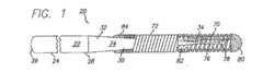
この発明は、スリーブあるいはハイポチューブを用いることなしに境界部分で接合される少なくとも2つのコア材料を有したガイドワイヤに向けられている。図1は、動脈あるいは静脈のような患者の体内管腔への挿入のために適合された、全体として20で表されている本発明のガイドワイヤの一実施形態の側面図を示している。この実施形態において、血管内ガイドワイヤ20は、ハイポチューブ、接続チューブあるいはスリーブを用いることなしに接合されあるいは固定される、少なくとも2つのコア材料を備えている。より詳しくは、このガイドワイヤ20は、近位端26および遠位端28を有する近位側コア部分24と、近位端32および遠位端34を有する遠位側コア部分30とを有しているコア22を備えている。近位側コア部分24をステンレス鋼から製造し、遠位側コア部分30をニチノールから製造することが好ましい。しかしながら、コア部分はガイドワイヤ技術において公知の任意の材料から作ることができる。 The present invention is directed to a guidewire having at least two core materials that are joined at the interface without the use of a sleeve or hypotube. FIG. 1 shows a side view of one embodiment of a guidewire of the present invention, generally designated 20, adapted for insertion into a patient's body lumen, such as an artery or vein. In this embodiment, the
図1に示した実施例においては、ガイドワイヤ20はまた、はんだあるいは溶接ビード82によって遠位端34に固定することができる形状可変部材(shapable member)70と、ヘリカルコイルのような柔軟な本体部分72とを有している。好ましくは、柔軟な本体部分72は、遠位側コア部分30の周りに配設されてはんだあるいは溶接ビード84によってそこに固定される。遠位側コア部分30は、随意的なテーパ状コア部分74と、このテーパ状コア部分74の遠位側に隣接する随意的な柔軟なコア部分76とを有する。柔軟なコア部分76の最も遠位側の部分は丸められた遠位端78となっている。もちろん、この丸められた遠位端78は他の形状および寸法とすることができるし、平らにしたりあるいは全く省略したりすることもできる。実際、コアに遠位端を連設する設計の他の実施形態においては、コア部分76が連続的に延びてガイドワイヤ20の最も遠位側の端部において丸められた先端80に係合する。 In the embodiment shown in FIG. 1, the
近位側コア部分24の遠位端28および遠位側コア部分30の近位端32(以下に接続端28,32と称する)は、互いに直線的に整列する。接続端28、32は、図3に示すように互いに補完し合う形状を有している。すなわち、図示の実施形態においては、接続端28、32は、互いに係合する細長い切り欠きあるいは面取りをそれぞれ有している。この互いに補完し合う形状の切り欠きは、接続部に沿って一定で小さな輪郭の外径をもたらす。さらに、接続部における細長い重なりは接着、溶接等の接合のための大きな表面積を呈しており、それによって接続強度を向上させる。さらに、この大きな重なりは、近位側コア部分24から遠位側コア部分30への効率的なトルク伝達を確実なものとしている。 The
硬化材料36が接続端28、32の間に配設され、および/またはこれらの接続端を包む。硬化材料36は、はんだ、ろう付、エポキシ、接着剤、レーザ溶接およびスポット溶接を含む溶接のための接合材料であるが、それらには限定されない。接続端28,32の間の接合部を形成するためにはんだを用いるとともに、このはんだがニッケルチタンフラックス400と共に用いるスズ銀95−5はんだであることが好ましい。しかしながら、コア材料を一体に接合するために、90−10を含む他の組成の銀スズはんだ、並びに金スズはんだのような、適切な強度を有した互換性のある任意のタイプのはんだを用いることができる。テストは、はんだで形成した接続部が、全般的に、ハイポチューブを用いて形成した接続部の2倍強いことを示している。 A
図2、図3および図10に示した実施形態においては、接続端28,32の互いに補完し合う形状がD字形断面40となっている。図10の断面図に示すように、D字形は真っ直ぐな縁を有する半円形である。他の断面形状、例えば卵形、三角形、台形、長方形および同様な多角形もまた考え得る。 In the embodiment shown in FIGS. 2, 3, and 10, the complementary shapes of the connection ends 28 and 32 are the D-shaped
図2は、近位側コア部分24の遠位端28の張り出した先端42を示しているが、この部分はD字形断面40に形成されている。それぞれがD字形断面40を有して一体に接続された接続端28,32を図3に見ることができる。この実施形態においては、D字形断面40の張り出し部分62が、好ましくは1cmの長さで延びつつ近位側コア部分24の円形断面形状に移行している。移行部分60は、図2に示したように徐々に湾曲しても良いし、段差状、あるいはより角度をなす輪郭とすることができる。他の実施形態において、張り出し部分62の長さは、最適な機能設計のための必要に応じて1mmから5cmの範囲とすることができる。当然、張り出し部分62の長さは、溶接、接着、はんだ付け等のために利用可能な境界部分の表面積の量に影響を与える。 FIG. 2 shows an overhanging tip 42 of the
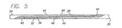
図5に示した他の実施形態においては、接続端28,32の互いに補完し合う形状が、テーパ46が設けられた背面44を有するD字形断面40となっている。この実施形態では、特に遠位側コア部分30の近位端32および近位側コア部分24の遠位端28の先端において、接合部の外径はその長さに沿って一定ではない。接続端28,32の一方にだけテーパ付けされた背面を設けることもまた可能である。この設計は、きつく曲げられたときに端部が「剥離」する潜在的な可能性を取り除くとともに、より柔軟で容易に湾曲する端部をもたらす。さらに、テーパ付き背面44の設計は、はんだのような硬化材料36が接続端28,32を少なくとも部分的に包むようにして潜在的な剥離の可能性を減少させる。 In the other embodiment shown in FIG. 5, the complementary shapes of the connection ends 28, 32 are D-shaped
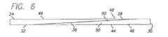
図6に示されているさらに他の実施形態においては、接続端28,32がテーパ付きのD字形断面48を有している。この実施形態において、テーパは、D字形断面48の前側50上に設けられているが、接続端28,32のいずれか一方のみをこのテーパ付きD字形断面48とすることも可能である。一つの実施例においては、接続端28,32をなすように研削されたテーパ付きD字形断面48の長さは3cmであるが、その長さは1cmから5cmの範囲とすることができる。図6の実施形態においては、遠位側コア部分30から近位側コア部分24へとより緩やかに移行しており、したがって異なる曲げ力でワイヤを用いるときに有益である。近位側コア部分の遠位端が互いに対向しつつ近位側に収束する仮想面を有するとともに、遠位側コア部分の近位端が互いに対向しつつ遠位側に収束する仮想面を有するように、接続端の前面および背面の両方にテーパ付けする実施形態もまた考え得る。 In yet another embodiment shown in FIG. 6, the connecting ends 28, 32 have a tapered D-shaped
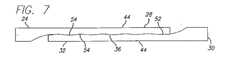
図7は、接続端28,32が係合する境界部分にセレーションが付けられた輪郭52が設けられている他の実施形態を示している。より複雑な境界部分、いくらかの摩擦係合、およびはんだのような硬化材料36がその内部に流入することができる追加的な隙間によって、セレーション54は、改良された接合強度を生じさせる芯出しジオメトリを提供する。セレーション54は、接合部における全体的な柱強度を改良するとともに曲げのための良好な柔軟性をもたらす。このような特性は、応力下において接合部が剥離する潜在的な可能性をさらに減少させる。この実施形態はまた、図8に示すようなセレーションが設けられたD字形の接続端18,32の背面44上にテーパ46を追加することによってより改良することができる。 FIG. 7 shows another embodiment in which a
図9に示すように、他の実施形態は、接続端28,32上に形成された、機械的に係合して互いに握持し合うロックセレーション56を有している。この実施形態は、接合プロセスの前にロックセレーション56が非接合状態で嵌り合う特徴を有しており、ろう付けあるいは接着のためにコアを適切に位置合わせした状態に保つための特有な芯出し治具の必要性をなくす。すなわち、接続端28,32のロックセレーション56は、接合あるいは接着のためのいかなる薬剤をも用いることなしに機械的に噛み合う互いに補完し合う歯を有しており、そのような薬剤は恒久的に部品を結合するために後に付加される。この機械的な噛み合いは、特注設備の必要性をなくすとともに、接合する部品の正確な芯合わせを可能とする。 As shown in FIG. 9, another embodiment has a
次に、ハイポチューブあるいはスリーブを用いることなしに本発明のガイドワイヤ20の前述した実施形態を製造する方法を説明する。一つの実施形態においては、上述した互いに補完し合う形状の一つあるいは他の任意の適切な形状が、研削、放電加工(EDM)、レーザ切断、あるいは従来技術において周知の他の任意の適切な方法によって接続端28,32に形成される。必要ならば、はんだ付け性を改良するために接続端28,32上の研削部分を金スズメッキしあるいはエッチングするといった追加の工程を実行することができる。接続端28,32を所望の形状に研削した後、接続端同士が互いに重なり合うように近位側および遠位側のコア部分24,30を向かい合わせにして治具内に配置する。はんだあるいは他の接合材料がその内部に入り込む小さな隙間38が接続端28,32の間にあるようにコア部分24,30を治具内に配置し、次いで2つのコア部分を互いに接合して固定する。はんだあるいは他の接合材料はまた、より強い結合をもたらすように接続端28,32を包むことができる。その後、接合した近位側および遠位側のコア部分24,30を所望の外径に研削する。実際の最終的な研削外径は、具体的なガイドワイヤの設計ニーズに応じて定まる。最終的な研削が完了すると、コア22の少なくとも一部あるいは全体に対して随意的にポリマ被覆を付加することができる。完成したガイドワイヤは、近位側コア部分24から遠位側コア部分30に至る接合部においてスムーズな断面輪郭を有する。 Next, a method of manufacturing the above-described embodiment of the
ガイドワイヤ20の接合部の完全性を改善するために、いくつかの追加の工程を実施することができる。より大きな結合強度を必要とするときには、互いに補完し合う形状を形成する前にあるいは形成した後に、接続端28,32をより小さな直径にプランジ研削することができる。例えば、0.0130インチの直径を0.010インチまでプランジ研削することができる。このより小さい直径は、接合されたコア部分24,30の外周全体にはんだあるいは他の接合材料を付加することができるようにする。図10は、D字形断面40を有している接続端28,32の、図3中における破断線10−10に沿った断面図を示しているが、この部分ははんだのような硬化材料36でコア部分24,30の外周全体を包むために、より小さな直径へとプランジ研削されている。実際に、このD字形断面40は、ガイドワイヤのコア22の直径の約半分あるいは僅かにより小さい外径へと随意的に研削される。また、上述したように、互いに補完し合う形状に形成された接続端28,32の背面44を研削してテーパ46を形成する。この特徴は、剥がれることなく湾曲する、より柔軟な端部をもたらすとともに、より多くのはんだが端部を包み込むようにする。 In order to improve the integrity of the
遠位側コア部分から近位側コア部分への緩やかな変化をもたらすために、接続端28,32をテーパ付けされたD字形断面40に研削することができる。同様に、セレーション54も研削によって形成することができる。 To provide a gradual change from the distal core portion to the proximal core portion, the connecting ends 28, 32 can be ground into a tapered D-shaped
本発明のさらに他の方法においては、接続端28,32が、一定のあるいはテーパ付けされたより小さな直径をもたらすためにプランジ研削される。一つの実施形態においては、この一定のあるいはテーパ付けされた小さな直径の長さは約1cmであるが、0.5〜5cmの長さとすることができる。必要ならば、はんだ付け性を改良するために接続端28,32上のプランジ研削部分を金スズメッキあるいはエッチングするといった追加の工程を実行することができる。プランジ研削されたコア部分24,30は、接続端28,32が互いに重なり合うように向かい合わせに治具内に配置される。次いで、2つのコア部分24,30を接合するために、はんだあるいは他の接合材料を重なり部分に沿って付加する。接合されたコア部分24,30は、それから所望の外径に研削される。この最終的な研削外径は、具体的なガイドワイヤの設計ニーズに応じて定まる。最終的な研削が完了すると、ポリマ被覆をコア22あるいはガイドワイヤ20に付加することができる。 In yet another method of the invention, the connecting ends 28, 32 are plunge ground to provide a constant or tapered smaller diameter. In one embodiment, the constant or tapered small diameter length is about 1 cm, but can be 0.5-5 cm long. If necessary, additional steps such as gold tin plating or etching of the plunge ground portions on the connection ends 28, 32 can be performed to improve solderability. The plunge-
開示した方法によって製造されるガイドワイヤがどのように用いられるかについては変更はない。記載した方法は、ハイポチューブあるいはスリーブを用いることなしに互いに接合される少なくとも2つのコア部分を有したガイドワイヤを生み出す。また、これらの方法は、任意の2つのワイヤを接合するために用いることができるとともに、遠位側コア部分の遠位端上に形状付けリボンを取り付けるためにさえ用いることができ、2つの重ね継手を有したガイドワイヤを生み出す。この実施例は、2つのコア材料における一つの重ね継手のために前述したのと同じ方法で互いに接続されあるいは接合される、少なくとも3つのコア材料を有している。一つの実施例は、ステンレス鋼部分とニチノール部分とを互いに接合する第1の重ね継手と、形状付けリボンとして作用するように形成することができる他のステンレス鋼部分とニチノール部分とを接合する第2の重ね継手とを有する。2つの重ね継手を形成した後、組立体を適切な寸法に研削する。さらに、この方法を使用することにより、ワイヤは任意の数のコア材料あるいは任意の数の重ね継手を含む、任意のワイヤを形成することができる。 There is no change in how guidewires manufactured by the disclosed method are used. The described method produces a guidewire having at least two core portions that are joined together without the use of hypotubes or sleeves. These methods can also be used to join any two wires and can even be used to attach a shaped ribbon on the distal end of the distal core portion, Produces a guide wire with a joint. This embodiment has at least three core materials that are connected or joined together in the same manner as described above for one lap joint in two core materials. One embodiment joins a first lap joint that joins a stainless steel portion and a nitinol portion to each other and another stainless steel portion that can be formed to act as a shaping ribbon and a nitinol portion. 2 lap joints. After forming the two lap joints, the assembly is ground to the appropriate dimensions. Further, by using this method, the wire can form any wire, including any number of core materials or any number of lap joints.
本発明の特定の形態を図示しかつ記載したが、本発明の精神および範囲から逸脱することなく、種々の改良をなしうることは当業者にとって明らかである。コア部分に用い材料のタイプを変更できることは明らかでなければならない。また、ガイドワイヤのサイズおよび寸法は、内径、外径、研削外径、長さおよび研削長さにおいて変更することができる。したがって、本発明が添付の請求の範囲による以外に限定されることは意図されない。 While particular forms of the invention have been illustrated and described, it will be apparent to those skilled in the art that various modifications can be made without departing from the spirit and scope of the invention. It should be clear that the type of material used for the core part can be changed. Also, the size and dimensions of the guide wire can be changed in terms of inner diameter, outer diameter, grinding outer diameter, length and grinding length. Accordingly, it is not intended that the invention be limited except by the appended claims.
Claims (39)
Translated fromJapanese前記近位側コア部分の遠位端を前記遠位側コア部分の近位端に接合する接合部に設けられる硬化材料と、を備え、
前記接合部がスリーブによって覆われていない
ことを特徴とする血管内ガイドワイヤ。A core having a proximal core portion having a proximal end and a distal end and a distal core portion having a proximal end and a distal end;
A curable material provided at a joint joining a distal end of the proximal core portion to a proximal end of the distal core portion;
An intravascular guide wire, wherein the joint is not covered with a sleeve.
近位端および遠位端を有する近位側コア部分と近位端および遠位端を有する遠位側コア部分とを有しているコアと、
前記近位側コア部分の遠位端および前記遠位側コア部分の近位端の間に配設された硬化材料と、を備え、
前記近位側コア部分の遠位端および前記遠位側コア部分の近位端が互いに補完し合うように整列している
ことを特徴とする血管内ガイドワイヤ。An intravascular guidewire having at least two core materials joined together without using a hypotube,
A core having a proximal core portion having a proximal end and a distal end and a distal core portion having a proximal end and a distal end;
A curable material disposed between a distal end of the proximal core portion and a proximal end of the distal core portion;
An intravascular guidewire wherein the distal end of the proximal core portion and the proximal end of the distal core portion are aligned so as to complement each other.
近位端および遠位端を有する近位側コア部分と近位端および遠位端を有する遠位側コア部分とを供給する段階と、
前記近位側コア部分の遠位端および前記遠位側コア部分の近位端に互いに補完し合う形状を形成する段階と、
前記近位側コア部分および前記遠位側コア部分を向かい合わせに位置決めする段階と、
前記近位側コア部分の遠位端と前記遠位側コア部分の近位端との間に隙間を開ける段階と、
前記近位側コア部分および前記遠位側コア部分を互いに接合する材料を前記隙間内に配設する段階と、
を備えることを特徴とする方法。A method of joining two endovascular guidewire core materials without using a hypotube,
Providing a proximal core portion having a proximal end and a distal end and a distal core portion having a proximal end and a distal end;
Forming complementary shapes on the distal end of the proximal core portion and the proximal end of the distal core portion;
Positioning the proximal core portion and the distal core portion face to face;
Opening a gap between the distal end of the proximal core portion and the proximal end of the distal core portion;
Disposing a material in the gap to join the proximal core portion and the distal core portion together;
A method comprising the steps of:
近位端および遠位端を有する近位側コア部分と近位端および遠位端を有する遠位側コア部分とを供給する段階と、
前記近位側コア部分の遠位端および前記遠位側コア部分の近位端の少なくとも一方をプランジ研削する段階と、
前記近位側コア部分および前記遠位側コア部分を向かい合わせに位置決めする段階と、
前記近位側コア部分の遠位端と前記遠位側コア部分の近位端との間に重なり部分を設ける段階と、
前記重なり部分に沿って硬化材料を付加する段階と、
接合した前記ガイドワイヤコア部分を所望の外径に研削する段階と、
を備えることを特徴とする方法。A method of joining at least two endovascular guidewire core materials without using a hypotube,
Providing a proximal core portion having a proximal end and a distal end and a distal core portion having a proximal end and a distal end;
Plunge grinding at least one of a distal end of the proximal core portion and a proximal end of the distal core portion;
Positioning the proximal core portion and the distal core portion face to face;
Providing an overlapping portion between a distal end of the proximal core portion and a proximal end of the distal core portion;
Adding a curable material along the overlap;
Grinding the joined guidewire core portions to a desired outer diameter;
A method comprising the steps of:
前記近位側コア部分および前記遠位側コア部分をスリーブを用いることなしに接合するための手段と、を備え
前記近位側コア部分の遠位端および前記遠位側コア部分の近位端とが互いに係合する補完し合う形状を有している
ことを特徴とする血管内ガイドワイヤ。A core having a proximal core portion having a proximal end and a distal end and a distal core portion having a proximal end and a distal end;
Means for joining the proximal core portion and the distal core portion without using a sleeve, comprising: a distal end of the proximal core portion and a proximal end of the distal core portion And a complementary guide wire that engages with each other.
近位端および遠位端を有する近位側コア部分と近位端および遠位端を有する遠位側コア部分とを有しているコアと、
前記近位側コア部分を前記遠位側コア部分に接合するために十分な強度を有し、かつ前記近位側コア部分の遠位端と前記遠位側コア部分の近位端との間の接合部に配設される硬化材料と、
を備えることを特徴とするガイドワイヤ。An intravascular guidewire,
A core having a proximal core portion having a proximal end and a distal end and a distal core portion having a proximal end and a distal end;
Strong enough to join the proximal core portion to the distal core portion and between the distal end of the proximal core portion and the proximal end of the distal core portion A curable material disposed at the joint of
A guide wire comprising:
近位端および遠位端を有する近位側コア部分と近位端および遠位端を有する遠位側コア部分とを供給する段階と、
前記近位側コア部分の遠位端および前記遠位側コア部分の近位端に互いに補完し合う形状を形成する段階と、
前記近位側コア部分および前記遠位側コア部分を向かい合わせに位置決めする段階と、
前記近位側コア部分の遠位端と前記遠位側コア部分の近位端との間に隙間を開ける段階と、
前記近位側コア部分を前記遠位側コア部分に接合するために十分な強度を有した硬化材料を前記隙間内に配設する段階と、
を備えることを特徴とする方法。A method of joining at least two endovascular guidewire core materials comprising:
Providing a proximal core portion having a proximal end and a distal end and a distal core portion having a proximal end and a distal end;
Forming complementary shapes on the distal end of the proximal core portion and the proximal end of the distal core portion;
Positioning the proximal core portion and the distal core portion face to face;
Opening a gap between the distal end of the proximal core portion and the proximal end of the distal core portion;
Disposing a hardened material in the gap having sufficient strength to join the proximal core portion to the distal core portion;
A method comprising the steps of:
Applications Claiming Priority (2)
| Application Number | Priority Date | Filing Date | Title |
|---|---|---|---|
| US10/032,873US6702762B2 (en) | 2001-12-27 | 2001-12-27 | Apparatus and method for joining two guide wire core materials without a hypotube |
| PCT/US2002/041391WO2003057273A2 (en) | 2001-12-27 | 2002-12-26 | Apparatus and method for joining two guide wire core materials without a hypotube |
Publications (2)
| Publication Number | Publication Date |
|---|---|
| JP2005514115Atrue JP2005514115A (en) | 2005-05-19 |
| JP2005514115A5 JP2005514115A5 (en) | 2005-12-22 |
Family
ID=21867294
Family Applications (1)
| Application Number | Title | Priority Date | Filing Date |
|---|---|---|---|
| JP2003557630APendingJP2005514115A (en) | 2001-12-27 | 2002-12-26 | Apparatus and method for joining two guidewire core materials without hypotube |
Country Status (4)
| Country | Link |
|---|---|
| US (2) | US6702762B2 (en) |
| JP (1) | JP2005514115A (en) |
| AU (1) | AU2002364235A1 (en) |
| WO (1) | WO2003057273A2 (en) |
Cited By (17)
| Publication number | Priority date | Publication date | Assignee | Title |
|---|---|---|---|---|
| JP2017513604A (en)* | 2014-04-21 | 2017-06-01 | コーニンクレッカ フィリップス エヌ ヴェKoninklijke Philips N.V. | Intravascular device, system and method having separate sections with core elements engaged |
| JP2020521529A (en)* | 2017-05-26 | 2020-07-27 | サイエンティア・バスキュラー・エルエルシー | Core-wire joint for microfabricated medical devices |
| JP2021526397A (en)* | 2018-06-05 | 2021-10-07 | メドトロニック・ヴァスキュラー・インコーポレーテッド | Medical catheter |
| US11207502B2 (en) | 2016-07-18 | 2021-12-28 | Scientia Vascular, Llc | Guidewire devices having shapeable tips and bypass cuts |
| US11305095B2 (en) | 2018-02-22 | 2022-04-19 | Scientia Vascular, Llc | Microfabricated catheter having an intermediate preferred bending section |
| US11369351B2 (en) | 2017-05-26 | 2022-06-28 | Scientia Vascular, Inc. | Micro-fabricated medical device having a non-helical cut arrangement |
| US11406791B2 (en) | 2009-04-03 | 2022-08-09 | Scientia Vascular, Inc. | Micro-fabricated guidewire devices having varying diameters |
| US11452541B2 (en) | 2016-12-22 | 2022-09-27 | Scientia Vascular, Inc. | Intravascular device having a selectively deflectable tip |
| US11951267B2 (en) | 2016-07-18 | 2024-04-09 | Scientia Vascular, Inc. | Guidewire devices having shapeable tips and bypass cuts |
| US12011555B2 (en) | 2019-01-15 | 2024-06-18 | Scientia Vascular, Inc. | Guidewire with core centering mechanism |
| US12178975B2 (en) | 2020-01-23 | 2024-12-31 | Scientia Vascular, Inc. | Guidewire having enlarged, micro-fabricated distal section |
| US12220538B2 (en) | 2008-12-08 | 2025-02-11 | Scientia Vascular, Inc. | Micro-fabricated intravascular devices having varying diameters |
| US12257399B2 (en) | 2018-06-05 | 2025-03-25 | Medtronic Vascular, Inc. | Medical catheter |
| US12296112B2 (en) | 2020-10-05 | 2025-05-13 | Scientia Vascular, Inc. | Microfabricated catheter devices with high axial strength |
| US12343485B2 (en) | 2020-01-23 | 2025-07-01 | Scientia Vascular, Inc. | High torque guidewire device |
| US12364840B2 (en) | 2016-07-29 | 2025-07-22 | Cephea Valve Technologies, Inc. | Mechanical interlock for catheters |
| US12440332B2 (en) | 2021-08-11 | 2025-10-14 | Cephea Valve Technologies, Inc. | Systems and methods for loading and deploying an intravascular device |
Families Citing this family (60)
| Publication number | Priority date | Publication date | Assignee | Title |
|---|---|---|---|---|
| US20030069522A1 (en) | 1995-12-07 | 2003-04-10 | Jacobsen Stephen J. | Slotted medical device |
| US20060047223A1 (en)* | 2004-08-31 | 2006-03-02 | Ryan Grandfield | Apparatus and method for joining stainless steel guide wire portion to nitinol portion, without a hypotube |
| US20030009208A1 (en)* | 2001-07-05 | 2003-01-09 | Precision Vascular Systems, Inc. | Torqueable soft tip medical device and method of usage |
| US6799067B2 (en)* | 2001-12-26 | 2004-09-28 | Advanced Cardiovascular Systems, Inc. | MRI compatible guide wire |
| US6702762B2 (en)* | 2001-12-27 | 2004-03-09 | Advanced Cardiovascular Systems, Inc. | Apparatus and method for joining two guide wire core materials without a hypotube |
| DE60334122D1 (en) | 2002-07-25 | 2010-10-21 | Boston Scient Ltd | MEDICAL DEVICE FOR NAVIGATING THROUGH ANATOMY |
| US7914467B2 (en) | 2002-07-25 | 2011-03-29 | Boston Scientific Scimed, Inc. | Tubular member having tapered transition for use in a medical device |
| JP4138583B2 (en) | 2002-08-08 | 2008-08-27 | テルモ株式会社 | Guide wire |
| JP4203358B2 (en)* | 2002-08-08 | 2008-12-24 | テルモ株式会社 | Guide wire |
| US7722551B2 (en)* | 2002-08-09 | 2010-05-25 | Terumo Kabushiki Kaisha | Guide wire |
| US7153277B2 (en)* | 2002-12-03 | 2006-12-26 | Scimed Life Systems, Inc. | Composite medical device with markers |
| US8377035B2 (en) | 2003-01-17 | 2013-02-19 | Boston Scientific Scimed, Inc. | Unbalanced reinforcement members for medical device |
| US7001369B2 (en) | 2003-03-27 | 2006-02-21 | Scimed Life Systems, Inc. | Medical device |
| WO2005053529A1 (en) | 2003-11-21 | 2005-06-16 | Radi Medical Systems Ab | Sensor and guide wire assembly |
| US7237313B2 (en)* | 2003-12-05 | 2007-07-03 | Boston Scientific Scimed, Inc. | Elongated medical device for intracorporal use |
| CN100558423C (en)* | 2003-12-18 | 2009-11-11 | 泰尔茂株式会社 | guide line |
| US7824345B2 (en) | 2003-12-22 | 2010-11-02 | Boston Scientific Scimed, Inc. | Medical device with push force limiter |
| US20050256401A1 (en)* | 2004-05-14 | 2005-11-17 | Scion Cardio-Vascular, Inc. | Catheter with variable diameter core spacing and associated actuated device |
| US7998090B2 (en) | 2004-08-31 | 2011-08-16 | Abbott Cardiovascular Systems Inc. | Guide wire with core having welded wire segments |
| DE602006014047D1 (en)* | 2005-04-15 | 2010-06-17 | Terumo Corp | guidewire |
| US20060237407A1 (en)* | 2005-04-25 | 2006-10-26 | Nguyen Anh V | Medical devices having laser brazed joints |
| US8043232B2 (en)* | 2005-08-05 | 2011-10-25 | Cook Medical Technologies Llc | High performance wire guide |
| US20080188793A1 (en)* | 2007-02-06 | 2008-08-07 | Possis Medical, Inc. | Miniature flexible thrombectomy catheter |
| US7850623B2 (en)* | 2005-10-27 | 2010-12-14 | Boston Scientific Scimed, Inc. | Elongate medical device with continuous reinforcement member |
| DE102006004900A1 (en)* | 2006-02-03 | 2007-08-16 | Viessmann Werke Gmbh & Co Kg | heater |
| US7731669B2 (en)* | 2006-05-12 | 2010-06-08 | Concert Medical, Llc | Guidewire formed with composite construction and method for making the same |
| WO2007145751A2 (en)* | 2006-05-12 | 2007-12-21 | Concert Medical Llc | Guidewire formed with composite construction and method for making the same |
| US8551020B2 (en)* | 2006-09-13 | 2013-10-08 | Boston Scientific Scimed, Inc. | Crossing guidewire |
| US8556914B2 (en) | 2006-12-15 | 2013-10-15 | Boston Scientific Scimed, Inc. | Medical device including structure for crossing an occlusion in a vessel |
| US7896820B2 (en)* | 2006-12-26 | 2011-03-01 | Terumo Kabushiki Kaisha | Guide wire |
| JP5214878B2 (en)* | 2006-12-28 | 2013-06-19 | テルモ株式会社 | Guide wire |
| US8206837B2 (en)* | 2007-01-12 | 2012-06-26 | Terumo Kabushiki Kaisha | Interventional medical device |
| JP4917900B2 (en)* | 2007-01-12 | 2012-04-18 | テルモ株式会社 | Intermediate member for guide wire and guide wire |
| US20080262474A1 (en)* | 2007-04-20 | 2008-10-23 | Boston Scientific Scimed, Inc. | Medical device |
| JP5295104B2 (en)* | 2007-05-09 | 2013-09-18 | 独立行政法人科学技術振興機構 | Guidewire and stent |
| US8409114B2 (en)* | 2007-08-02 | 2013-04-02 | Boston Scientific Scimed, Inc. | Composite elongate medical device including distal tubular member |
| US20090036832A1 (en)* | 2007-08-03 | 2009-02-05 | Boston Scientific Scimed, Inc. | Guidewires and methods for manufacturing guidewires |
| US8105246B2 (en)* | 2007-08-03 | 2012-01-31 | Boston Scientific Scimed, Inc. | Elongate medical device having enhanced torque and methods thereof |
| US8821477B2 (en) | 2007-08-06 | 2014-09-02 | Boston Scientific Scimed, Inc. | Alternative micromachined structures |
| US20090043228A1 (en)* | 2007-08-06 | 2009-02-12 | Boston Scientific Scimed, Inc. | Laser shock peening of medical devices |
| US9808595B2 (en)* | 2007-08-07 | 2017-11-07 | Boston Scientific Scimed, Inc | Microfabricated catheter with improved bonding structure |
| US7841994B2 (en) | 2007-11-02 | 2010-11-30 | Boston Scientific Scimed, Inc. | Medical device for crossing an occlusion in a vessel |
| US20090177119A1 (en)* | 2008-01-03 | 2009-07-09 | Boston Scientific Scimed, Inc. | Articulating intracorporeal medical device |
| US8376961B2 (en) | 2008-04-07 | 2013-02-19 | Boston Scientific Scimed, Inc. | Micromachined composite guidewire structure with anisotropic bending properties |
| US20100063479A1 (en)* | 2008-09-10 | 2010-03-11 | Boston Scientific Scimed, Inc. | Small profile, tubular component design and method of manufacture |
| US8535243B2 (en)* | 2008-09-10 | 2013-09-17 | Boston Scientific Scimed, Inc. | Medical devices and tapered tubular members for use in medical devices |
| US8795254B2 (en)* | 2008-12-10 | 2014-08-05 | Boston Scientific Scimed, Inc. | Medical devices with a slotted tubular member having improved stress distribution |
| US8137293B2 (en) | 2009-11-17 | 2012-03-20 | Boston Scientific Scimed, Inc. | Guidewires including a porous nickel-titanium alloy |
| US8551021B2 (en) | 2010-03-31 | 2013-10-08 | Boston Scientific Scimed, Inc. | Guidewire with an improved flexural rigidity profile |
| US8500658B2 (en) | 2010-10-28 | 2013-08-06 | Abbott Cardiovascular Systems Inc. | Nickel-titanium core guide wire |
| US8795202B2 (en) | 2011-02-04 | 2014-08-05 | Boston Scientific Scimed, Inc. | Guidewires and methods for making and using the same |
| US9072874B2 (en) | 2011-05-13 | 2015-07-07 | Boston Scientific Scimed, Inc. | Medical devices with a heat transfer region and a heat sink region and methods for manufacturing medical devices |
| US9061088B2 (en) | 2012-02-02 | 2015-06-23 | Abbott Cardiovascular Systems, Inc. | Guide wire core wire made from a substantially titanium-free alloy for enhanced guide wire steering response |
| USD684258S1 (en)* | 2012-03-29 | 2013-06-11 | Biotronik Ag | Hypotube hub |
| US9636485B2 (en) | 2013-01-17 | 2017-05-02 | Abbott Cardiovascular Systems, Inc. | Methods for counteracting rebounding effects during solid state resistance welding of dissimilar materials |
| US10124437B2 (en) | 2013-08-19 | 2018-11-13 | Covidien Lp | Laser welding of nickel titanium alloys |
| US9901706B2 (en) | 2014-04-11 | 2018-02-27 | Boston Scientific Scimed, Inc. | Catheters and catheter shafts |
| US11351048B2 (en) | 2015-11-16 | 2022-06-07 | Boston Scientific Scimed, Inc. | Stent delivery systems with a reinforced deployment sheath |
| CN109199658B (en)* | 2017-07-03 | 2024-03-29 | 深圳市科奕顿生物医疗科技有限公司 | Self-expanding type lumen stent and manufacturing method thereof |
| CN209154121U (en)* | 2017-07-03 | 2019-07-26 | 深圳市科奕顿生物医疗科技有限公司 | A kind of self-inflated bifurcated intraluminal stent |
Family Cites Families (18)
| Publication number | Priority date | Publication date | Assignee | Title |
|---|---|---|---|---|
| US4875489A (en) | 1987-08-14 | 1989-10-24 | Advanced Cardiovascular Systems, Inc. | Extendable guidewire |
| US4827941A (en) | 1987-12-23 | 1989-05-09 | Advanced Cardiovascular Systems, Inc. | Extendable guidewire for cardiovascular procedures |
| US4966163A (en) | 1989-02-14 | 1990-10-30 | Advanced Cardiovascular Systems, Inc. | Extendable guidewire for vascular procedures |
| JP3297434B2 (en) | 1990-04-10 | 2002-07-02 | ボストン サイエンティフィック コーポレーション | Highly stretchable linear elastic guidewire |
| US5341818A (en) | 1992-12-22 | 1994-08-30 | Advanced Cardiovascular Systems, Inc. | Guidewire with superelastic distal portion |
| US6165292A (en) | 1990-12-18 | 2000-12-26 | Advanced Cardiovascular Systems, Inc. | Superelastic guiding member |
| US5213111A (en) | 1991-07-10 | 1993-05-25 | Cook Incorporated | Composite wire guide construction |
| US5546958A (en)* | 1994-03-31 | 1996-08-20 | Lake Region Manufacturing Company, Inc. | Guidewire extension system with tactile connection indication |
| DE69637107T2 (en) | 1995-02-28 | 2008-02-28 | Boston Scientific Corp., Natick | Device made of polymer for transmitting a torque |
| US5513650A (en)* | 1995-02-28 | 1996-05-07 | Medtronic, Inc. | Guidewire extension connector - keyed joint |
| US5666968A (en)* | 1995-03-17 | 1997-09-16 | Intelliwire, Inc. | Flexible guide wire with extension capability and guide wire extension for use therewith |
| US5853375A (en)* | 1995-11-29 | 1998-12-29 | Medtronic, Inc. | Guide wire extension peg and hole with 90 degree latch |
| US6001068A (en) | 1996-10-22 | 1999-12-14 | Terumo Kabushiki Kaisha | Guide wire having tubular connector with helical slits |
| US5980471A (en) | 1997-10-10 | 1999-11-09 | Advanced Cardiovascular System, Inc. | Guidewire with tubular connector |
| US6284089B1 (en)* | 1997-12-23 | 2001-09-04 | The Boeing Company | Thermoplastic seam welds |
| US6328822B1 (en)* | 1998-06-26 | 2001-12-11 | Kiyohito Ishida | Functionally graded alloy, use thereof and method for producing same |
| US6544197B2 (en)* | 2000-10-20 | 2003-04-08 | Radius Medical Technologies, Inc. | Composite guidewire |
| US6702762B2 (en)* | 2001-12-27 | 2004-03-09 | Advanced Cardiovascular Systems, Inc. | Apparatus and method for joining two guide wire core materials without a hypotube |
- 2001
- 2001-12-27USUS10/032,873patent/US6702762B2/ennot_activeExpired - Lifetime
- 2002
- 2002-12-26AUAU2002364235Apatent/AU2002364235A1/ennot_activeAbandoned
- 2002-12-26WOPCT/US2002/041391patent/WO2003057273A2/enactiveApplication Filing
- 2002-12-26JPJP2003557630Apatent/JP2005514115A/enactivePending
- 2004
- 2004-02-03USUS10/772,086patent/US20040181176A1/ennot_activeAbandoned
Cited By (28)
| Publication number | Priority date | Publication date | Assignee | Title |
|---|---|---|---|---|
| US12220538B2 (en) | 2008-12-08 | 2025-02-11 | Scientia Vascular, Inc. | Micro-fabricated intravascular devices having varying diameters |
| US11406791B2 (en) | 2009-04-03 | 2022-08-09 | Scientia Vascular, Inc. | Micro-fabricated guidewire devices having varying diameters |
| US11864918B2 (en) | 2014-04-21 | 2024-01-09 | Philips Image Guided Therapy Corporation | Intravascular devices, systems, and methods having separate sections with engaged core components |
| JP2020000914A (en)* | 2014-04-21 | 2020-01-09 | コーニンクレッカ フィリップス エヌ ヴェKoninklijke Philips N.V. | Intravascular devices, systems, and methods having separate sections with engaged core components |
| US10772564B2 (en) | 2014-04-21 | 2020-09-15 | Koninklijke Philips N.V. | Intravascular devices, systems, and methods having separate sections with engaged core components |
| JP2017513604A (en)* | 2014-04-21 | 2017-06-01 | コーニンクレッカ フィリップス エヌ ヴェKoninklijke Philips N.V. | Intravascular device, system and method having separate sections with core elements engaged |
| US11207502B2 (en) | 2016-07-18 | 2021-12-28 | Scientia Vascular, Llc | Guidewire devices having shapeable tips and bypass cuts |
| US12115324B2 (en) | 2016-07-18 | 2024-10-15 | Scientia Vascular, Inc. | Guidewire devices having shapeable polymer tips |
| US11951267B2 (en) | 2016-07-18 | 2024-04-09 | Scientia Vascular, Inc. | Guidewire devices having shapeable tips and bypass cuts |
| US11890434B2 (en) | 2016-07-18 | 2024-02-06 | Scientia Vascular, Inc. | Guidewire devices having distally extending coils and shapeable tips |
| US12364840B2 (en) | 2016-07-29 | 2025-07-22 | Cephea Valve Technologies, Inc. | Mechanical interlock for catheters |
| US11452541B2 (en) | 2016-12-22 | 2022-09-27 | Scientia Vascular, Inc. | Intravascular device having a selectively deflectable tip |
| US11369351B2 (en) | 2017-05-26 | 2022-06-28 | Scientia Vascular, Inc. | Micro-fabricated medical device having a non-helical cut arrangement |
| JP7116747B2 (en) | 2017-05-26 | 2022-08-10 | サイエンティア・バスキュラー・エルエルシー | Core-wire joints for microfabricated medical devices |
| JP2020521529A (en)* | 2017-05-26 | 2020-07-27 | サイエンティア・バスキュラー・エルエルシー | Core-wire joint for microfabricated medical devices |
| US12310567B2 (en) | 2017-05-26 | 2025-05-27 | Scientia Vascular, Inc. | Micro-fabricated medical device having a non-helical cut arrangement |
| US12053595B2 (en) | 2018-02-22 | 2024-08-06 | Scientia Vascular, Inc. | Microfabricated catheter having an intermediate preferred bending section |
| US11305095B2 (en) | 2018-02-22 | 2022-04-19 | Scientia Vascular, Llc | Microfabricated catheter having an intermediate preferred bending section |
| US12311129B2 (en) | 2018-06-05 | 2025-05-27 | Medtronic Vascular, Inc. | Medical catheter |
| US11654263B2 (en) | 2018-06-05 | 2023-05-23 | Medtronic Vascular, Inc. | Medical catheter |
| JP7353303B2 (en) | 2018-06-05 | 2023-09-29 | メドトロニック・ヴァスキュラー・インコーポレーテッド | medical catheter |
| JP2021526397A (en)* | 2018-06-05 | 2021-10-07 | メドトロニック・ヴァスキュラー・インコーポレーテッド | Medical catheter |
| US12257399B2 (en) | 2018-06-05 | 2025-03-25 | Medtronic Vascular, Inc. | Medical catheter |
| US12011555B2 (en) | 2019-01-15 | 2024-06-18 | Scientia Vascular, Inc. | Guidewire with core centering mechanism |
| US12178975B2 (en) | 2020-01-23 | 2024-12-31 | Scientia Vascular, Inc. | Guidewire having enlarged, micro-fabricated distal section |
| US12343485B2 (en) | 2020-01-23 | 2025-07-01 | Scientia Vascular, Inc. | High torque guidewire device |
| US12296112B2 (en) | 2020-10-05 | 2025-05-13 | Scientia Vascular, Inc. | Microfabricated catheter devices with high axial strength |
| US12440332B2 (en) | 2021-08-11 | 2025-10-14 | Cephea Valve Technologies, Inc. | Systems and methods for loading and deploying an intravascular device |
Also Published As
| Publication number | Publication date |
|---|---|
| WO2003057273A3 (en) | 2004-01-22 |
| US20040181176A1 (en) | 2004-09-16 |
| AU2002364235A8 (en) | 2003-07-24 |
| AU2002364235A1 (en) | 2003-07-24 |
| US20030125641A1 (en) | 2003-07-03 |
| US6702762B2 (en) | 2004-03-09 |
| WO2003057273A2 (en) | 2003-07-17 |
Similar Documents
| Publication | Publication Date | Title |
|---|---|---|
| JP2005514115A (en) | Apparatus and method for joining two guidewire core materials without hypotube | |
| US6866642B2 (en) | Enhanced method for joining two core wires | |
| JP4203358B2 (en) | Guide wire | |
| US7722551B2 (en) | Guide wire | |
| JP4138582B2 (en) | Guide wire | |
| JP2024105725A (en) | Mechanisms for improving stiffness transition across dissimilar metal welded joints | |
| CN101642600A (en) | Guide wire | |
| US6740050B2 (en) | Intracorporeal member with improved transition section | |
| JPH1157014A (en) | Guide wire | |
| JP4734015B2 (en) | Guide wire manufacturing method | |
| JP4783343B2 (en) | Guide wire | |
| JP4375951B2 (en) | Guide wire | |
| JP5328835B2 (en) | Guide wire manufacturing method | |
| JP3962652B2 (en) | Guide wire | |
| JP7747453B2 (en) | Balloon catheter | |
| JP4447597B2 (en) | Guide wire | |
| EP1523366B1 (en) | Guidewire with tapered flexible core segment | |
| JP5296143B2 (en) | Guide wire | |
| JP4116944B2 (en) | Guide wire | |
| JP4455808B2 (en) | Guide wire | |
| JP2006325687A (en) | Guide wire | |
| JP2008110266A (en) | Guide wire | |
| JP2004065794A (en) | Guide wire | |
| JP5135452B2 (en) | Guide wire | |
| JP2007307422A (en) | Guide wire |
Legal Events
| Date | Code | Title | Description |
|---|---|---|---|
| A131 | Notification of reasons for refusal | Free format text:JAPANESE INTERMEDIATE CODE: A131 Effective date:20070410 | |
| A601 | Written request for extension of time | Free format text:JAPANESE INTERMEDIATE CODE: A601 Effective date:20070710 | |
| A602 | Written permission of extension of time | Free format text:JAPANESE INTERMEDIATE CODE: A602 Effective date:20070718 | |
| A521 | Request for written amendment filed | Free format text:JAPANESE INTERMEDIATE CODE: A523 Effective date:20070810 | |
| A02 | Decision of refusal | Free format text:JAPANESE INTERMEDIATE CODE: A02 Effective date:20080104 |