JP2005352024A - Glasses type interface device and security system - Google Patents
Glasses type interface device and security systemDownload PDFInfo
- Publication number
- JP2005352024A JP2005352024AJP2004171009AJP2004171009AJP2005352024AJP 2005352024 AJP2005352024 AJP 2005352024AJP 2004171009 AJP2004171009 AJP 2004171009AJP 2004171009 AJP2004171009 AJP 2004171009AJP 2005352024 AJP2005352024 AJP 2005352024A
- Authority
- JP
- Japan
- Prior art keywords
- unit
- interface device
- type interface
- wireless communication
- communication unit
- Prior art date
- Legal status (The legal status is an assumption and is not a legal conclusion. Google has not performed a legal analysis and makes no representation as to the accuracy of the status listed.)
- Pending
Links
Images


Classifications
- A—HUMAN NECESSITIES
- A61—MEDICAL OR VETERINARY SCIENCE; HYGIENE
- A61B—DIAGNOSIS; SURGERY; IDENTIFICATION
- A61B5/00—Measuring for diagnostic purposes; Identification of persons
- A61B5/117—Identification of persons
- A61B5/1171—Identification of persons based on the shapes or appearances of their bodies or parts thereof
- A—HUMAN NECESSITIES
- A61—MEDICAL OR VETERINARY SCIENCE; HYGIENE
- A61B—DIAGNOSIS; SURGERY; IDENTIFICATION
- A61B3/00—Apparatus for testing the eyes; Instruments for examining the eyes
- A61B3/10—Objective types, i.e. instruments for examining the eyes independent of the patients' perceptions or reactions
- A61B3/14—Arrangements specially adapted for eye photography
- A61B3/145—Arrangements specially adapted for eye photography by video means
- A—HUMAN NECESSITIES
- A61—MEDICAL OR VETERINARY SCIENCE; HYGIENE
- A61B—DIAGNOSIS; SURGERY; IDENTIFICATION
- A61B5/00—Measuring for diagnostic purposes; Identification of persons
- A61B5/117—Identification of persons
- G—PHYSICS
- G02—OPTICS
- G02B—OPTICAL ELEMENTS, SYSTEMS OR APPARATUS
- G02B27/00—Optical systems or apparatus not provided for by any of the groups G02B1/00 - G02B26/00, G02B30/00
- G02B27/01—Head-up displays
- G02B27/017—Head mounted
- G—PHYSICS
- G02—OPTICS
- G02C—SPECTACLES; SUNGLASSES OR GOGGLES INSOFAR AS THEY HAVE THE SAME FEATURES AS SPECTACLES; CONTACT LENSES
- G02C11/00—Non-optical adjuncts; Attachment thereof
- G02C11/06—Hearing aids
- G—PHYSICS
- G02—OPTICS
- G02C—SPECTACLES; SUNGLASSES OR GOGGLES INSOFAR AS THEY HAVE THE SAME FEATURES AS SPECTACLES; CONTACT LENSES
- G02C11/00—Non-optical adjuncts; Attachment thereof
- G02C11/10—Electronic devices other than hearing aids
- G—PHYSICS
- G06—COMPUTING OR CALCULATING; COUNTING
- G06V—IMAGE OR VIDEO RECOGNITION OR UNDERSTANDING
- G06V40/00—Recognition of biometric, human-related or animal-related patterns in image or video data
- G06V40/10—Human or animal bodies, e.g. vehicle occupants or pedestrians; Body parts, e.g. hands
- G06V40/18—Eye characteristics, e.g. of the iris
- G—PHYSICS
- G07—CHECKING-DEVICES
- G07C—TIME OR ATTENDANCE REGISTERS; REGISTERING OR INDICATING THE WORKING OF MACHINES; GENERATING RANDOM NUMBERS; VOTING OR LOTTERY APPARATUS; ARRANGEMENTS, SYSTEMS OR APPARATUS FOR CHECKING NOT PROVIDED FOR ELSEWHERE
- G07C9/00—Individual registration on entry or exit
- G07C9/30—Individual registration on entry or exit not involving the use of a pass
- G07C9/32—Individual registration on entry or exit not involving the use of a pass in combination with an identity check
- G07C9/37—Individual registration on entry or exit not involving the use of a pass in combination with an identity check using biometric data, e.g. fingerprints, iris scans or voice recognition
- A—HUMAN NECESSITIES
- A61—MEDICAL OR VETERINARY SCIENCE; HYGIENE
- A61B—DIAGNOSIS; SURGERY; IDENTIFICATION
- A61B3/00—Apparatus for testing the eyes; Instruments for examining the eyes
- A61B3/10—Objective types, i.e. instruments for examining the eyes independent of the patients' perceptions or reactions
- A61B3/12—Objective types, i.e. instruments for examining the eyes independent of the patients' perceptions or reactions for looking at the eye fundus, e.g. ophthalmoscopes
- G—PHYSICS
- G02—OPTICS
- G02B—OPTICAL ELEMENTS, SYSTEMS OR APPARATUS
- G02B27/00—Optical systems or apparatus not provided for by any of the groups G02B1/00 - G02B26/00, G02B30/00
- G02B27/01—Head-up displays
- G02B27/0101—Head-up displays characterised by optical features
- G02B2027/0138—Head-up displays characterised by optical features comprising image capture systems, e.g. camera
- G—PHYSICS
- G02—OPTICS
- G02B—OPTICAL ELEMENTS, SYSTEMS OR APPARATUS
- G02B27/00—Optical systems or apparatus not provided for by any of the groups G02B1/00 - G02B26/00, G02B30/00
- G02B27/01—Head-up displays
- G02B27/0179—Display position adjusting means not related to the information to be displayed
- G02B2027/0187—Display position adjusting means not related to the information to be displayed slaved to motion of at least a part of the body of the user, e.g. head, eye
Landscapes
- Physics & Mathematics (AREA)
- Health & Medical Sciences (AREA)
- Engineering & Computer Science (AREA)
- Life Sciences & Earth Sciences (AREA)
- General Physics & Mathematics (AREA)
- General Health & Medical Sciences (AREA)
- Ophthalmology & Optometry (AREA)
- Optics & Photonics (AREA)
- Biophysics (AREA)
- Medical Informatics (AREA)
- Multimedia (AREA)
- Acoustics & Sound (AREA)
- Human Computer Interaction (AREA)
- Biomedical Technology (AREA)
- Heart & Thoracic Surgery (AREA)
- Otolaryngology (AREA)
- Molecular Biology (AREA)
- Surgery (AREA)
- Animal Behavior & Ethology (AREA)
- Public Health (AREA)
- Veterinary Medicine (AREA)
- Pathology (AREA)
- Theoretical Computer Science (AREA)
- Eyeglasses (AREA)
Abstract
Description
Translated fromJapaneseこの発明は、眼鏡とインタフェースとが一体化した眼鏡型インタフェース装置及びこの眼鏡型インタフェース装置を用いて人間の網膜の同一性を認識するセキュリティシステムに関するものである。 The present invention relates to a spectacle-type interface device in which spectacles and an interface are integrated, and a security system that recognizes the identity of a human retina using the spectacle-type interface device.
近年、建物への入出門時に、入出門者の網膜を検知し、網膜情報の同一性の有無によって、入出門の許可を決定するセキュリティシステムが普及しつつある。
しかし、このセキュリティシステムは、入出門者が、建物などの出入り口に備え付けられているカメラに目を当て、カメラがこの目の網膜を撮影した後、別体の処理装置がこの網膜情報と登録網膜情報との同一性を判断して、出入り口を開閉するシステムであるため、入出門するまでに長時間を要してしまう。
そこで、眼鏡とインタフェースとを一体化し、眼鏡に取り付けられたカメラで撮影した網膜などの画像情報を内蔵コンピュータなどで処理して同一性の判断を可能にした眼鏡型インタフェース装置が提案されている(例えば、特許文献1参照)。In recent years, security systems that detect entrance / exiting retinas when entering or exiting buildings and determine permission to enter / exit based on the presence or absence of the identity of retina information are becoming widespread.
However, in this security system, an introductory person looks at the camera installed at the entrance of a building or the like, and after the camera takes a picture of the retina of the eye, a separate processing device uses the retina information and the registered retina. Since it is a system that opens and closes the entrance by judging the identity with the information, it takes a long time to enter the entrance.
Therefore, a spectacle-type interface device has been proposed in which spectacles and an interface are integrated, and image information such as a retina photographed by a camera attached to the spectacles is processed by a built-in computer or the like to enable determination of identity ( For example, see Patent Document 1).
しかしながら、上記した従来の眼鏡型インタフェース装置は、カメラで撮影した網膜などの画像を処理する高速コンピュータを眼鏡のテンプル等に内蔵させた構造であるので、装置自体の重量が大きくなり、この眼鏡をかけたユーザに不快感を与えるおそれがある。また、コンピュータなどへの電力供給をモダン部などに内蔵したバッテリーで行うため、コンピュータの駆動時間が短く、頻繁に充電又は電池交換を行わなければならず、使い勝手が非常に悪い。 However, the above-described conventional eyeglass-type interface device has a structure in which a high-speed computer that processes an image of a retina taken by a camera is built in a temple of eyeglasses. There is a risk of discomfort for the user who has applied. In addition, since power supply to a computer or the like is performed by a battery built in the modern part or the like, the drive time of the computer is short, frequent charging or battery replacement must be performed, and usability is very poor.
この発明は、上述した課題を解決するためになされたもので、軽量で且つ使い勝手がよい眼鏡型インタフェース装置及びセキュリティシステムを提供することを目的とする。 The present invention has been made in order to solve the above-described problems, and an object of the present invention is to provide an eyeglass-type interface device and a security system that are lightweight and easy to use.
上記課題を解決するために、請求項1記載の発明は、眼鏡のレンズ枠又はテンプルに装着され、使用者の眼球の一部を撮像してその撮像信号を出力するカメラ部と、当該眼鏡のモダン部又はテンプルに装着され、カメラ部からの撮像信号を電波で送信する無線通信部と、当該眼鏡のレンズ枠,テンプル又はモダン部のいずれかに装着され、カメラ部及び無線通信部に電力を供給する自己発電型の発電部とを具備する構成とした。
かかる構成により、使用者がこの眼鏡型インタフェース装置をかけると、使用者の眼球の一部がカメラ部によって撮像され、その撮像信号が出力される。すると、この撮像信号が無線通信部によって電波で送信される。また、これらカメラ部及び無線通信部には、発電部によって電力が供給される。In order to solve the above-described problem, the invention described in
With this configuration, when the user puts on the glasses-type interface device, a part of the user's eyeball is imaged by the camera unit, and the imaging signal is output. Then, this imaging signal is transmitted by radio waves by the wireless communication unit. In addition, power is supplied to the camera unit and the wireless communication unit by a power generation unit.
請求項2の発明は、請求項1に記載の眼鏡型インタフェース装置において、眼球の一部は、網膜又は瞳孔である構成とした。
かかる構成により、眼球の網膜又は瞳孔がカメラ部によって撮像され、撮像信号として無線送信される。According to a second aspect of the present invention, in the eyeglass-type interface device according to the first aspect, a part of the eyeball is a retina or a pupil.
With this configuration, the retina or pupil of the eyeball is imaged by the camera unit and wirelessly transmitted as an imaging signal.
請求項3の発明は、請求項1または請求項2に記載の眼鏡型インタフェース装置において、無線通信部から入力された各種情報を表示するためのディスプレイ部を眼鏡の一対のレンズの少なくとも一方に設けた構成とする。
かかる構成により、レンズに設けられたディスプレイ部によって、無線通信部から入力された各種情報が表示される。According to a third aspect of the present invention, in the eyeglass-type interface device according to the first or second aspect, a display unit for displaying various information input from the wireless communication unit is provided on at least one of the pair of lenses of the spectacles. The configuration is as follows.
With this configuration, various information input from the wireless communication unit is displayed on the display unit provided in the lens.
請求項4の発明は、請求項1ないし請求項3のいずれかに記載の眼鏡型インタフェース装置において、無線通信部を通じて音声などの送受信が可能なイヤホンとマイクロフォンとを有するオーディオ部を当該眼鏡のモダン部又はテンプルに設けた構成とする。
かかる構成により、オーディオ部のイヤホンへの音声等やマイクロフォンからの音声などが、無線通信部を通じて送受信される。According to a fourth aspect of the present invention, in the eyeglass-type interface device according to any one of the first to third aspects, an audio unit having an earphone and a microphone capable of transmitting and receiving voice and the like through a wireless communication unit is provided as a modern part of the spectacles. It is set as the structure provided in the part or the temple.
With such a configuration, audio to the earphone of the audio unit, audio from the microphone, and the like are transmitted and received through the wireless communication unit.
請求項5の発明は、請求項1ないし請求項4のいずれかに記載の眼鏡型インタフェース装置において、発電部は、太陽電池又はサーモジェネレータである構成とした。
かかる構成により、電池交換などの必要がなくなり、使い勝手が向上する。According to a fifth aspect of the present invention, in the eyeglass-type interface device according to any one of the first to fourth aspects, the power generation unit is a solar cell or a thermogenerator.
Such a configuration eliminates the need for battery replacement and improves usability.
請求項6の発明は、請求項1ないし請求項5のいずれかに記載の眼鏡型インタフェース装置において、イヤホンは、骨伝導イヤホンである構成とした。
かかる構成により、使用者は、鼓膜でなく、骨を通じて音声などの情報を得ることができる。According to a sixth aspect of the present invention, in the eyeglass-type interface device according to any one of the first to fifth aspects, the earphone is a bone conduction earphone.
With this configuration, the user can obtain information such as sound through the bone instead of the eardrum.
請求項7の発明は、請求項1ないし請求項6のいずれかに記載の眼鏡型インタフェース装置において、無線通信部は、UWBの無線方式で通信を行う通信部である構成とした。
かかる構成により、無線通信部が、超高速近距離無線方式であるUWBの方式で通信を行うので、ノイズの少ない超広帯域の通信が可能となる。According to a seventh aspect of the present invention, in the eyeglass-type interface device according to any one of the first to sixth aspects, the wireless communication unit is a communication unit that performs communication in a UWB wireless system.
With this configuration, since the wireless communication unit performs communication using the UWB method, which is an ultra-high-speed short-range wireless method, ultra-wideband communication with less noise is possible.
請求項8の発明は、請求項1ないし請求項7のいずれかに記載の眼鏡型インタフェース装置と、管理装置とを備えるセキュリティシステムであって、管理装置は、眼鏡型インタフェース装置の無線通信部から送信された撮像信号を受信する受信部と、この受信部で受信した撮像信号を画像情報に処理する画像処理部と、この画像処理部で得た画像情報が、登録された複数の画像情報のいずれかと同一か否かを判断する判断部とを備える構成とした。
かかる構成により、使用者の眼鏡型インタフェース装置から送信された撮像信号は、管理装置の受信部で受信された後、画像処理部で画像情報に処理される。すると、判断部によって、この画像処理部で得た画像情報が、登録された複数の画像情報のいずれかと同一か否かが判断される。The invention of
With this configuration, the imaging signal transmitted from the user's glasses-type interface device is received by the receiving unit of the management device and then processed into image information by the image processing unit. Then, the determination unit determines whether the image information obtained by the image processing unit is the same as any one of the plurality of registered image information.
以上詳しく説明したように、請求項1ないし請求項6に記載の発明に係る眼鏡型インタフェース装置よれば、使用者がこの眼鏡型インタフェース装置をかけると、使用者の眼球の一部がカメラ部によって直ちに撮像されるので、眼球の一部に対する認識時間を短くすることができる。また、カメラ部で撮像した信号に対して複雑な画像処理を行うことなく、撮像信号として出力し、この撮像信号を無線通信部によって電波で送信する構成であるので、画像処理のための高速コンピュータなどを内蔵させる必要がなく、その分、装置の軽量化を図ることができる。さらに、電力を食うコンピュータを必要としないので、その分電源を長持ちさせることができる。また、カメラ部及び無線通信部への電力供給を自己発電型の発電部によって行うので、半永久的に使用することができる。 As described above in detail, according to the spectacles type interface device according to the first to sixth aspects of the present invention, when the user puts on the spectacles type interface device, a part of the user's eyeball is formed by the camera unit. Since the image is picked up immediately, the recognition time for a part of the eyeball can be shortened. In addition, since the image captured by the camera unit is output as an imaged signal without performing complicated image processing, and this imaged signal is transmitted by radio waves by the wireless communication unit, a high-speed computer for image processing Etc., and the weight of the apparatus can be reduced accordingly. In addition, since a computer that consumes power is not required, the power source can be made longer. In addition, since the power supply to the camera unit and the wireless communication unit is performed by the self-power generation type power generation unit, it can be used semipermanently.
また、請求項3の発明によれば、使用者は、レンズに設けられたディスプレイ部によって、無線通信部から入力された各種情報を見ることができるので、非常に便利である。
また、請求項4の発明によれば、使用者が音声などの情報も得ることができる。
また、請求項5の発明によれば、発電部が、太陽電池又はサーモジェネレータであるので、装置のさらなる軽量化を図ることができる。
また、請求項6の発明によれば、使用者の耳が不自由な場合においても、音声などの情報を得ることができる。
請求項コイル7の発明によれば、無線通信部が、UWBの方式で超広帯域の通信を行うことができるので、携帯電話,PDA,ノートパソコン等の外部器機と大容量の情報の送受信が可能となる。According to the invention of
According to the invention of
According to the invention of claim 5, since the power generation unit is a solar cell or a thermo-generator, the device can be further reduced in weight.
According to the invention of
According to the invention of
請求項8の発明に係るセキュリティシステムによれば、眼鏡型インタフェース装置では、撮像信号のみを作成して送信し、この撮像信号に対応した画像情報は管理装置側で処理するので、処理時間が短くて済む。
また、個人特有の模様をなす網膜又は瞳孔を眼鏡型インタフェース装置のカメラ部によって撮像するようにすることで、判断部における画像情報の同一性の判断を極めて精確に行うことができる。According to the security system of the eighth aspect of the invention, in the eyeglass-type interface device, only the imaging signal is generated and transmitted, and the image information corresponding to this imaging signal is processed on the management device side, so the processing time is short. I'll do it.
In addition, since the retina or pupil having a pattern peculiar to an individual is imaged by the camera unit of the glasses-type interface device, the determination of the identity of the image information in the determination unit can be performed very accurately.
以下、この発明の最良の形態について図面を参照して説明する。 The best mode of the present invention will be described below with reference to the drawings.
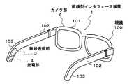
図1は、この発明の第1実施例に係る眼鏡型インタフェース装置を示す斜視図である。
この眼鏡型インタフェース装置1は、眼鏡100にインタフェースを一体化させた構成となっており、インタフェースは、カメラ部2と無線通信部3と発電部4とを有してなる。FIG. 1 is a perspective view showing an eyeglass-type interface device according to a first embodiment of the present invention.
The eyeglass-
カメラ部2は、使用者の眼球の一部である網膜を撮像してその撮像信号を無線通信部3に出力する部分である。
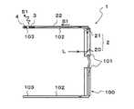
図2は、カメラ部2の構造を示す概略平面図である。
図2に示すように、カメラ部2は、ミラー20とセンサ21とで構成されている。ミラー20は、反射面が使用者の眼球側(図2の左側)に所定角度傾けた状態で、眼鏡100のレンズ枠101の内側に装着されている。また、センサ21は、CCD素子などで形成されており、テンプル102近傍のレンズ枠101の部位にミラー20側を向いた状態で装着され、その出力側がテンプル102内に通されたライン22を介して無線通信部3と接続されている。
これにより、眼鏡型インタフェース装置1をかけている使用者の眼球内にある網膜からの光Lを、ミラー20でセンサ21側に反射させ、センサ21がこの反射した光Lを受光する。そして、センサ21は、受光した光Lを電気信号としての撮像信号S1に変換して、無線通信部3に出力する。なお、図示しないが、センサ21の前段にはレンズが設けられ、このレンズを移動させて焦点調整をすることができるようになっている。The
FIG. 2 is a schematic plan view showing the structure of the
As shown in FIG. 2, the
As a result, the light L from the retina in the eyeball of the user wearing the glasses-
無線通信部3は、カメラ部2からの撮像信号S1を電波で送信する部分であり、眼鏡100のモダン部103に装着されている。この無線通信部3は、周知のUWB(Ultra Wideband)の無線方式で通信を行う通信部である。このため、3.1GHz〜10.6GHzという非常に広い周波数帯域を利用して無線通信が可能となっている。 The
発電部4は、カメラ部2及び無線通信部3に電力を供給するための部分であり、眼鏡100のモダン部103に装着されている。この発電部4は、自己発電型の電池であり、この実施例では、可視高透過型の太陽電池を用いている。 The
次に、この実施例の眼鏡型インタフェース装置1が示す作用及び効果について説明する。
図3に示すように、使用者Pが眼鏡型インタフェース装置1をかけると、図2に示したように、使用者Pの網膜からの光Lがカメラ部2のミラー20で反射され、センサ21で受光される。そして、この受光された光Lがセンサ21によって電気信号に変換され撮像信号S1として、無線通信部3に出力される。すると、撮像信号S1が電波に変調されて無線通信部3から送信される。このとき、無線通信部3が、UWBの広帯域な無線通信を行うことができるので、使用者Pは、所有している携帯電話,PDA,ノートパソコン等の外部器機と通信することができる。したがって、使用者Pは、撮像信号S1が示す自己の網膜情報を携帯電話などのディスプレイで見ることができる。Next, the operation and effect of the eyeglass-
As shown in FIG. 3, when the user P puts on the eyeglass-
このように、眼鏡型インタフェース装置1では、使用者Pが眼鏡型インタフェース装置1をかけると、使用者Pの網膜がカメラ部2によって直ちに撮像されるので、眼鏡型インタフェース装置1における網膜に対する認識及び処理時間を短くすることができる。
また、撮像した信号に対して画像処理を行うことなく、撮像信号S1として、無線通信部3から電波で送信する構成であるので、画像処理のための高速コンピュータなどを装着させる必要がなく、その分、装置の軽量化を図ることができる。さらに、電力を食うコンピュータを必要としないので、その分電源を長持ちさせることができる。
また、発電部4が、自己発電型の電池であるので、カメラ部2及び無線通信部3への電力供給を半永久的に行うことができる。さらに、発電部4が軽量な太陽電池であるので、眼鏡型インタフェース装置1のさらなる軽量化を図ることができる。As described above, in the glasses-
In addition, since the captured signal S1 is transmitted by radio waves from the
Further, since the
次に、この発明の第2実施例について説明する。
図4は、第2実施例の要部を示す眼鏡型インタフェース装置1の平面図である。
図4に示すように、この実施例の眼鏡型インタフェース装置1は、ディスプレイ部5を有している点が、上記第1実施例と異なる。
すなわち、眼鏡型インタフェース装置1は、眼鏡100の1対のレンズ104の双方にディスプレイ部5を有している。具体的には、映写部50がテンプル102に装着されている。そして、この映写部50側に反射面を向けて傾くミラー51がレンズ104に設けられると共に、ビームスプリッタ52が、ミラー51と対向するようにレンズ104に設けられている。
2つの映写部50は、共にライン53を介して無線通信部3に接続されており、各種の映像信号が無線通信部3から映写部50に入力されるようになっている。これにより、映写部50から映写された映像光Vがミラー51で反射された後、ビームスプリッタ52を介して、使用者の眼球側に至る。Next explained is the second embodiment of the invention.
FIG. 4 is a plan view of the eyeglass-
As shown in FIG. 4, the eyeglass-
That is, the eyeglass-
The two
かかる構成により、携帯電話などの外部器機から無線通信部3に送られてきた映像情報が、ディスプレイ部5によって、レンズ104に表示されるので、使用者は眼鏡型インタフェース装置1をかけたまま携帯電話などから取得した情報を見ることができ、非常に便利である。
その他の構成、作用及び効果は上記第1実施例と同様であるので、その記載は省略する。With this configuration, the video information transmitted from the external device such as a mobile phone to the
Since other configurations, operations, and effects are the same as those of the first embodiment, description thereof is omitted.
次に、この発明の第3実施例について説明する。
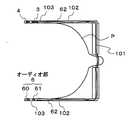
図5は、第3実施例の要部を示す眼鏡型インタフェース装置1の平面図である。
図5に示すように、この実施例の眼鏡型インタフェース装置1は、オーディオ部6を有している点が、上記第1及び第2実施例と異なる。
図5に示すように、オーディオ部6は、眼鏡100のモダン部103に設けられている。このオーディオ部6は、骨伝導イヤホン60とマイクロフォン61とを有してなり、一方のテンプル102とレンズ枠101と他方のテンプル102とを通ったライン62を介して無線通信部3と接続している。
これにより、音声などの音情報を、無線通信部3を通じて送受信することができる。すなわち、携帯電話などの外部器機から無線通信部3に送られてきた音情報が、オーディオ部6の骨伝導イヤホン60に送信され、使用者Pは骨を通じてこの音情報を聞くことができる。また、使用者Pが発した音情報は、オーディオ部6のマイクロフォン61で捉えられ、ライン62を通じて無線通信部3に送られる。これにより、この音情報が、無線通信部3から携帯電話などに送信される。
このように、この実施例の眼鏡型インタフェース装置1によれば、使用者Pが、鼓膜でなく、骨を通じて音声などの情報を得ることができるので、耳が不自由な場合においても、音声などの情報を確実に得ることができる。
その他の構成、作用及び効果は上記第1及び第2実施例と同様であるので、その記載は省略する。Next explained is the third embodiment of the invention.
FIG. 5 is a plan view of the eyeglass-
As shown in FIG. 5, the eyeglass-
As shown in FIG. 5, the
Thereby, sound information such as voice can be transmitted and received through the
As described above, according to the eyeglass-
Since other configurations, operations, and effects are the same as those in the first and second embodiments, description thereof is omitted.
次に、この発明の第4実施例について説明する。
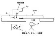
図6は、第4実施例に係るセキュリティシステムを示す概略図であり、図7は管理装置のブロック図である。
この実施例のセキュリティシステムは、図6に示すように、建物の出入り口300を開閉する入出門200を通る人の同一性を識別して、通過の可否を決定するシステムである。Next explained is the fourth embodiment of the invention.
FIG. 6 is a schematic diagram showing a security system according to the fourth embodiment, and FIG. 7 is a block diagram of the management apparatus.
As shown in FIG. 6, the security system of this embodiment is a system that identifies the identity of a person passing through an entrance /
このセキュリティシステムは、眼鏡型インタフェース装置1と管理装置7とを備えてなる。
眼鏡型インタフェース装置1は、上記第3実施例の眼鏡型インタフェース装置であり、管理装置7は、入出門200の開閉を管理する装置である。This security system includes an eyeglass-
The glasses-
管理装置7は、入出門200を機械的に開閉させるための開閉機構8を制御する制御信号S2を開閉機構8に出力することができる装置である。
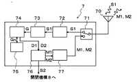
具体的には、管理装置7は、図7に示すように、アンテナ70が接続されたディプレクサ71の後段に配された受信部72と画像処理部73と判断部74と登録部75と駆動部76と送信部77とを有している。The
Specifically, as illustrated in FIG. 7, the
受信部72は、アンテナ70からディプレクサ71を通じて受信した撮像信号S1を受信して復調し、その撮像信号S1を画像処理部73に送る部分である。
画像処理部73は、受信部72からの撮像信号S1を画像情報Gに処理して、判断部74に出力する部分である。
判断部74は、画像処理部73からの画像情報Gと、登録部75に登録されている複数の画像情報Gnとを比較し、画像情報Gが、複数の画像情報Gnのいずれかと同一か否かを判断する部分である。また、判断部74は、画像情報Gが、複数の画像情報Gnのいずれかと同一の場合、すなわち、複数の画像情報Gnの中に画像情報Gと同一の画像情報Gnが存在した場合には、許可信号D1を駆動部76に出力する。また、画像情報Gと同一の画像情報Gnが存在しない場合には、拒否信号D2を駆動部76に出力するようになっている。駆動部76は、許可信号D1を判断部74から受けた場合に、入出門200を開かせる制御信号S2を開閉機構8に出力すると共に、許可に関するメッセージM1を送信部77に出力する部分である。また、拒否信号D2を判断部74から受けた場合には、入出門200の閉状態を維持させる制御信号S2を開閉機構8に出力すると共に、拒否される理由などのメッセージM2を送信部77に出力する。
送信部77は、メッセージM1,M2を変調し、これらのメッセージM1,M2をディプレクサ71及びアンテナ70を介して、眼鏡型インタフェース装置1に送信する部分である。The receiving
The
The
The
かかる構成により、入出門者Pが図6に示す眼鏡型インタフェース装置1をかけると、入出門者Pの網膜がカメラ部2によって撮像され、その撮像信号S1が管理装置7に送信される。
すると、撮像信号S1が図7に示す管理装置7のアンテナ70で受けられ、ディプレクサ71を通じて受信部72に受信されて復調される。そして、復調された撮像信号S1が画像処理部73で画像情報Gに変換され、画像情報Gが判断部74に出力される。With this configuration, when the introductory person P puts on the eyeglass-
Then, the imaging signal S1 is received by the
これにより、入出門者Pの網膜の画像情報Gが、判断部74によって登録部75に登録されている複数の画像情報Gnと比較される。そして、画像情報Gが画像情報Gnのいずれかと同一である場合、すなわち、入出門者Pが網膜情報の登録を管理装置7にした者である場合には、許可信号D1が判断部74から駆動部76に出力される。すると、入出門200を開かせる制御信号S2が駆動部76からを開閉機構8に出力され、入出門200が開閉機構8によって開かれる。これと並行して、許可に関するメッセージM1が送信部77に出力され、アンテナ70を介して眼鏡型インタフェース装置1に送信される。
このメッセージM1は、眼鏡型インタフェース装置1の無線通信部3によって受信され、ディスプレイ部5によってレンズ104に表示される。Thereby, the image information G of the retina of the introductory person P is compared with the plurality of pieces of image information Gn registered in the
The message M1 is received by the
逆に、画像情報Gが画像情報Gnのいずれかと同一でない場合、すなわち、入出門者Pが網膜情報の登録を管理装置7にした者でない場合には、拒否信号D2が判断部74から駆動部76に出力され、入出門200の閉状態を維持させる制御信号S2が駆動部76からを開閉機構8に出力される。これにより、入出門200は閉じた状態を維持し、入出門者Pは出入り口300から建物の中に入ることができない。また、これと並行して、拒否される理由などのメッセージM2が送信部77に出力され、アンテナ70を介して眼鏡型インタフェース装置1に送信されて、そのメッセージM2の内容が、眼鏡型インタフェース装置1のディスプレイ部5によってレンズ104に表示される。
その他の構成、作用及び効果は上記第1ないし第3実施例と同様であるので、その記載は省略する。Conversely, if the image information G is not the same as any of the image information Gn, that is, if the introductory person P is not the person who has registered the retina information in the
Since other configurations, operations, and effects are the same as those in the first to third embodiments, description thereof is omitted.
なお、この発明は、上記実施例に限定されるものではなく、発明の要旨の範囲内において種々の変形や変更が可能である。
例えば、上記実施例では、眼球の網膜をカメラ部2の撮像対象としたが、瞳孔を撮像対象としても良い。
また、上記実施例では、センサ21の前段に、図示しないレンズを設け、このレンズを移動させて焦点調整をすることができるようにしたが、この焦点調整を自動的に行うようにすることができることは勿論である。
また、上記実施例では、発電部として、太陽電池を用いたが、太陽電池の代わりに、体温で発電するサーモジェネレータを用いてもよい。
また、上記実施例では、無線通信部として、UWBの無線方式で通信を行う無線通信部3を用いたが、通常の無線方式で通信を行うものを採用しても良い。
また、上記第3実施例では、オーディオ部6のイヤホンとして、骨伝導イヤホン60を用いたが、健聴者が使用する通常のイヤホンを用いても良い。In addition, this invention is not limited to the said Example, A various deformation | transformation and change are possible within the range of the summary of invention.
For example, in the above embodiment, the retina of the eyeball is the imaging target of the
In the above-described embodiment, a lens (not shown) is provided in front of the
Moreover, in the said Example, although the solar cell was used as an electric power generation part, you may use the thermogenerator which generate | occur | produces with body temperature instead of a solar cell.
In the above-described embodiment, the
Moreover, in the said 3rd Example, although the
1…眼鏡型インタフェース装置、 2…カメラ部、 3…無線通信部、 4…発電部、 5…ディスプレイ部、 6…オーディオ部、 7…管理装置、 8…開閉機構、 20,51…ミラー、 21…センサ、 22,53,62…ライン、 50…映写部、 52…ビームスプリッタ、 60…骨伝導イヤホン、 61…マイクロフォン、 70…アンテナ、 71…ディプレクサ、 72…受信部、 73…画像処理部、 74…判断部、 75…登録部、 76…駆動部、 77…送信部、 100…眼鏡、 101…レンズ枠、 102…テンプル、 103…モダン部、 104…レンズ、 D1…許可信号、 D2…拒否信号、 G,Gn…画像情報、 L…光、 M1,M2…メッセージ、 P…使用者、 S1…撮像信号、 S2…制御信号、 V…映像光。 DESCRIPTION OF
Claims (8)
Translated fromJapanese当該眼鏡のモダン部又はテンプルに装着され、上記カメラ部からの撮像信号を電波で送信する無線通信部と、
当該眼鏡のレンズ枠,テンプル又はモダン部のいずれかに装着され、上記カメラ部及び無線通信部に電力を供給する自己発電型の発電部と
を具備することを特徴とする眼鏡型インタフェース装置。A camera unit that is mounted on a lens frame or a temple of spectacles, images a part of a user's eyeball, and outputs an imaging signal;
A wireless communication unit that is mounted on a modern part or temple of the glasses and transmits an imaging signal from the camera unit by radio waves;
An eyeglass-type interface device comprising: a self-power generation type power generation unit that is attached to any of a lens frame, a temple, or a modern part of the spectacles and supplies power to the camera unit and the wireless communication unit.
ことを特徴とする請求項1に記載の眼鏡型インタフェース装置。A portion of the eyeball is the retina or pupil;
The eyeglass-type interface device according to claim 1.
ことを特徴とする請求項1または請求項2に記載の眼鏡型インタフェース装置。A display unit for displaying various information input from the wireless communication unit is provided on at least one of the pair of lenses of the glasses,
The eyeglass-type interface device according to claim 1 or 2, characterized in that
ことを特徴とする請求項1ないし請求項3のいずれかに記載の眼鏡型インタフェース装置。An audio unit having an earphone and a microphone capable of transmitting and receiving voice and the like through the wireless communication unit is provided in the modern part or temple of the glasses,
The eyeglass-type interface device according to any one of claims 1 to 3, wherein
ことを特徴とする請求項1ないし請求項4のいずれかに記載の眼鏡型インタフェース装置。The power generation unit is a solar cell or a thermogenerator.
The spectacles type interface device according to any one of claims 1 to 4, wherein
ことを特徴とする請求項1ないし請求項5のいずれかに記載の眼鏡型インタフェース装置。The earphone is a bone conduction earphone,
The eyeglass-type interface device according to any one of claims 1 to 5, wherein
ことを特徴とする請求項1ないし請求項6のいずれかに記載の眼鏡型インタフェース装置。The wireless communication unit is a communication unit that performs communication using the UWB wireless method.
The spectacles type interface device according to any one of claims 1 to 6.
上記管理装置は、
上記眼鏡型インタフェース装置の上記無線通信部から送信された上記撮像信号を受信する受信部と、
この受信部で受信した撮像信号を画像情報に処理する画像処理部と、
この画像処理部で得た画像情報が、登録された複数の画像情報のいずれかと同一か否かを判断する判断部とを備える、
ことを特徴とするセキュリティシステム。A security system comprising the glasses-type interface device according to any one of claims 1 to 7 and a management device,
The management device
A receiving unit that receives the imaging signal transmitted from the wireless communication unit of the glasses-type interface device;
An image processing unit that processes image signals received by the receiving unit into image information;
A determination unit that determines whether the image information obtained by the image processing unit is the same as any one of the plurality of registered image information;
Security system characterized by that.
Priority Applications (2)
| Application Number | Priority Date | Filing Date | Title |
|---|---|---|---|
| JP2004171009AJP2005352024A (en) | 2004-06-09 | 2004-06-09 | Glasses type interface device and security system |
| US11/144,712US20050275714A1 (en) | 2004-06-09 | 2005-06-06 | Eyeglass interface device and security system |
Applications Claiming Priority (1)
| Application Number | Priority Date | Filing Date | Title |
|---|---|---|---|
| JP2004171009AJP2005352024A (en) | 2004-06-09 | 2004-06-09 | Glasses type interface device and security system |
Publications (1)
| Publication Number | Publication Date |
|---|---|
| JP2005352024Atrue JP2005352024A (en) | 2005-12-22 |
Family
ID=35460087
Family Applications (1)
| Application Number | Title | Priority Date | Filing Date |
|---|---|---|---|
| JP2004171009APendingJP2005352024A (en) | 2004-06-09 | 2004-06-09 | Glasses type interface device and security system |
Country Status (2)
| Country | Link |
|---|---|
| US (1) | US20050275714A1 (en) |
| JP (1) | JP2005352024A (en) |
Cited By (22)
| Publication number | Priority date | Publication date | Assignee | Title |
|---|---|---|---|---|
| JP2011033749A (en)* | 2009-07-31 | 2011-02-17 | Toshiba Corp | Display device and spectacles |
| WO2012001891A1 (en)* | 2010-06-30 | 2012-01-05 | パナソニック株式会社 | Optical device |
| US8092011B2 (en) | 2009-03-25 | 2012-01-10 | Olympus Corporation | Eyeglass-mounted type image display device |
| WO2012090947A1 (en) | 2010-12-27 | 2012-07-05 | ローム株式会社 | Transmitter/receiver unit and receiver unit |
| JP2012231259A (en)* | 2011-04-25 | 2012-11-22 | Kyocera Corp | Head-mounted display |
| WO2013108426A1 (en) | 2012-01-20 | 2013-07-25 | ローム株式会社 | Portable telephone having cartilage conduction section |
| US8521239B2 (en) | 2010-12-27 | 2013-08-27 | Rohm Co., Ltd. | Mobile telephone |
| US8918149B2 (en) | 2010-12-27 | 2014-12-23 | Rohm Co., Ltd. | Mobile telephone |
| WO2015025829A1 (en) | 2013-08-23 | 2015-02-26 | ローム株式会社 | Portable telephone |
| KR20150021958A (en) | 2012-06-29 | 2015-03-03 | 로무 가부시키가이샤 | Stereo earphone |
| KR20150118851A (en)* | 2014-04-15 | 2015-10-23 | 해성옵틱스(주) | Eyeglasses for iris recognition |
| US9313306B2 (en) | 2010-12-27 | 2016-04-12 | Rohm Co., Ltd. | Mobile telephone cartilage conduction unit for making contact with the ear cartilage |
| US9485559B2 (en) | 2011-02-25 | 2016-11-01 | Rohm Co., Ltd. | Hearing system and finger ring for the hearing system |
| US9705548B2 (en) | 2013-10-24 | 2017-07-11 | Rohm Co., Ltd. | Wristband-type handset and wristband-type alerting device |
| KR20170084301A (en) | 2014-12-18 | 2017-07-19 | 로무 가부시키가이샤 | Cartilage conduction hearing device using electromagnetic-type vibration unit, and electromagnetic-type vibration unit |
| US10013862B2 (en) | 2014-08-20 | 2018-07-03 | Rohm Co., Ltd. | Watching system, watching detection device, and watching notification device |
| KR20180095071A (en) | 2016-01-19 | 2018-08-24 | 로무 가부시키가이샤 | Pen-type transmitter and receiver |
| US10425813B2 (en) | 2014-11-19 | 2019-09-24 | Canon Kabushiki Kaisha | Authentication management method, information processing apparatus, wearable device, and computer program |
| US10795321B2 (en) | 2015-09-16 | 2020-10-06 | Finewell Co., Ltd. | Wrist watch with hearing function |
| JP2020204671A (en)* | 2019-06-14 | 2020-12-24 | 有限会社 ブリッヂコーポレーション | Eyeglasses |
| US10967521B2 (en) | 2015-07-15 | 2021-04-06 | Finewell Co., Ltd. | Robot and robot system |
| US11526033B2 (en) | 2018-09-28 | 2022-12-13 | Finewell Co., Ltd. | Hearing device |
Families Citing this family (45)
| Publication number | Priority date | Publication date | Assignee | Title |
|---|---|---|---|---|
| US20120105740A1 (en) | 2000-06-02 | 2012-05-03 | Oakley, Inc. | Eyewear with detachable adjustable electronics module |
| US8482488B2 (en) | 2004-12-22 | 2013-07-09 | Oakley, Inc. | Data input management system for wearable electronically enabled interface |
| US7013009B2 (en) | 2001-06-21 | 2006-03-14 | Oakley, Inc. | Eyeglasses with wireless communication features |
| US9153074B2 (en)* | 2011-07-18 | 2015-10-06 | Dylan T X Zhou | Wearable augmented reality eyeglass communication device including mobile phone and mobile computing via virtual touch screen gesture control and neuron command |
| US11829518B1 (en) | 2004-07-28 | 2023-11-28 | Ingeniospec, Llc | Head-worn device with connection region |
| US11852901B2 (en) | 2004-10-12 | 2023-12-26 | Ingeniospec, Llc | Wireless headset supporting messages and hearing enhancement |
| US12044901B2 (en) | 2005-10-11 | 2024-07-23 | Ingeniospec, Llc | System for charging embedded battery in wireless head-worn personal electronic apparatus |
| US11733549B2 (en) | 2005-10-11 | 2023-08-22 | Ingeniospec, Llc | Eyewear having removable temples that support electrical components |
| EP2124729A1 (en)* | 2006-11-17 | 2009-12-02 | Balance International Innovations Gmbh | System and method for providing body sway feedback to a body of a subject |
| EP2095178B1 (en) | 2006-12-14 | 2015-08-12 | Oakley, Inc. | Wearable high resolution audio visual interface |
| US20090156128A1 (en)* | 2007-12-12 | 2009-06-18 | Motorola, Inc. | Eyewear communications system |
| GB2465002A (en)* | 2008-11-04 | 2010-05-12 | Immortal Creations Ltd | Video recording glasses |
| CN101753221A (en) | 2008-11-28 | 2010-06-23 | 新兴盛科技股份有限公司 | Butterfly temporal bone conduction communication and/or hearing aid device |
| US8649776B2 (en)* | 2009-01-13 | 2014-02-11 | At&T Intellectual Property I, L.P. | Systems and methods to provide personal information assistance |
| JP2012058530A (en)* | 2010-09-09 | 2012-03-22 | Seiko Epson Corp | Shutter spectacles and image display system |
| JP2012249097A (en)* | 2011-05-27 | 2012-12-13 | Kyocera Corp | Speech output device |
| US20130141313A1 (en)* | 2011-07-18 | 2013-06-06 | Tiger T.G. Zhou | Wearable personal digital eyeglass device |
| US20130022220A1 (en)* | 2011-07-20 | 2013-01-24 | Google Inc. | Wearable Computing Device with Indirect Bone-Conduction Speaker |
| US20130169513A1 (en)* | 2012-01-04 | 2013-07-04 | Google Inc. | Wearable computing device |
| US9529197B2 (en)* | 2012-03-21 | 2016-12-27 | Google Inc. | Wearable device with input and output structures |
| CN204331191U (en) | 2012-02-17 | 2015-05-13 | 奥克利有限公司 | Glasses and dual attachment members |
| US20140064536A1 (en)* | 2012-08-28 | 2014-03-06 | Google Inc. | Thin Film Bone-Conduction Transducer for a Wearable Computing System |
| US9129429B2 (en) | 2012-10-24 | 2015-09-08 | Exelis, Inc. | Augmented reality on wireless mobile devices |
| ITMI20121842A1 (en)* | 2012-10-30 | 2014-05-01 | Glassup S R L A Capitale Ridotto | GLASSES FOR INCREASED REALITY |
| CN103852890B (en)* | 2012-11-28 | 2017-05-24 | 联想(北京)有限公司 | Head-Mounted Electronic Device And Audio Processing Method |
| US9854196B2 (en) | 2012-11-28 | 2017-12-26 | Beijing Lenovo Software Ltd. | Head-mounted electronic device and audio processing method |
| CN103974174B (en)* | 2013-02-01 | 2018-08-10 | 联想(北京)有限公司 | Voice transmission module, apparatus for processing audio and electronic equipment |
| KR102081797B1 (en)* | 2012-12-13 | 2020-04-14 | 삼성전자주식회사 | Glass apparatus and Method for controlling glass apparatus, Audio apparatus and Method for providing audio signal and Display apparatus |
| EP2973533A4 (en) | 2013-03-15 | 2016-11-30 | Oakley Inc | ELECTRONIC ORNAMENTATION FOR EYEWEAR |
| CN205691887U (en) | 2013-06-12 | 2016-11-16 | 奥克利有限公司 | Modular communication system and glasses communication system |
| US9442294B2 (en)* | 2013-06-27 | 2016-09-13 | Koc Universitesi | Image display device in the form of a pair of eye glasses comprising micro reflectors |
| US9143848B2 (en)* | 2013-07-15 | 2015-09-22 | Google Inc. | Isolation of audio transducer |
| US9298010B2 (en) | 2014-08-08 | 2016-03-29 | Marissa J. Sundquist | Wearable optical display with audio functionality |
| US9800570B1 (en) | 2014-09-26 | 2017-10-24 | Adt Us Holdings, Inc. | Method of persistent authentication with disablement upon removal of a wearable device |
| CN104267513A (en)* | 2014-10-20 | 2015-01-07 | 印波 | Glasses capable of monitoring ambient conditions in real time |
| US9596536B2 (en)* | 2015-07-22 | 2017-03-14 | Google Inc. | Microphone arranged in cavity for enhanced voice isolation |
| CN106888350A (en)* | 2015-12-15 | 2017-06-23 | 北京奇虎科技有限公司 | Processing method of taking pictures, intelligent glasses and user terminal based on intelligent glasses |
| CN105788043A (en)* | 2016-03-03 | 2016-07-20 | 陈健强 | Automobile unlocking achieving method and system based on intelligent spectacle iris recognition |
| CA3018877A1 (en)* | 2016-04-06 | 2017-10-12 | Marc Allan Harris | Wearable personal security devices and systems |
| SE540788C2 (en)* | 2017-03-13 | 2018-11-13 | Skugga Tech Ab | Eyewear with wireless charging means |
| CN110058413A (en)* | 2018-05-23 | 2019-07-26 | 王小峰 | A kind of intelligence donning system |
| WO2020038481A1 (en)* | 2018-08-24 | 2020-02-27 | 深圳市韶音科技有限公司 | Spectacles |
| WO2021000127A1 (en)* | 2019-06-29 | 2021-01-07 | 瑞声声学科技(深圳)有限公司 | Smart wearable eyeglasses |
| KR102861695B1 (en)* | 2020-09-08 | 2025-09-18 | 삼성전자주식회사 | Wearable electronic device including speaker module |
| US12186019B2 (en)* | 2023-04-07 | 2025-01-07 | Globe Biomedical, Inc | Mechanical integration of components of wearable devices and ocular health monitoring system |
Family Cites Families (4)
| Publication number | Priority date | Publication date | Assignee | Title |
|---|---|---|---|---|
| CA2307877C (en)* | 1997-10-30 | 2005-08-30 | The Microoptical Corporation | Eyeglass interface system |
| US7023594B2 (en)* | 2000-06-23 | 2006-04-04 | E-Vision, Llc | Electro-optic lens with integrated components |
| US6769767B2 (en)* | 2001-04-30 | 2004-08-03 | Qr Spex, Inc. | Eyewear with exchangeable temples housing a transceiver forming ad hoc networks with other devices |
| US6757408B2 (en)* | 2002-01-25 | 2004-06-29 | Robert C. Houvener | Quality assurance and training system for high volume mobile identity verification system and method |
- 2004
- 2004-06-09JPJP2004171009Apatent/JP2005352024A/enactivePending
- 2005
- 2005-06-06USUS11/144,712patent/US20050275714A1/ennot_activeAbandoned
Cited By (66)
| Publication number | Priority date | Publication date | Assignee | Title |
|---|---|---|---|---|
| US8092011B2 (en) | 2009-03-25 | 2012-01-10 | Olympus Corporation | Eyeglass-mounted type image display device |
| JP2011033749A (en)* | 2009-07-31 | 2011-02-17 | Toshiba Corp | Display device and spectacles |
| KR101364942B1 (en)* | 2010-06-30 | 2014-02-19 | 파나소닉 주식회사 | Optical device |
| WO2012001891A1 (en)* | 2010-06-30 | 2012-01-05 | パナソニック株式会社 | Optical device |
| US9256077B2 (en) | 2010-06-30 | 2016-02-09 | Panasonic Intellectual Property Management Co., Ltd. | Optical device |
| JP5436668B2 (en)* | 2010-06-30 | 2014-03-05 | パナソニック株式会社 | Optical device |
| KR20150032600A (en) | 2010-12-27 | 2015-03-26 | 로무 가부시키가이샤 | Transmitter/receiver unit and receiver unit |
| WO2012090944A1 (en) | 2010-12-27 | 2012-07-05 | ローム株式会社 | Mobile telephone |
| US9894430B2 (en) | 2010-12-27 | 2018-02-13 | Rohm Co., Ltd. | Incoming/outgoing-talk unit and incoming-talk unit |
| WO2012090947A1 (en) | 2010-12-27 | 2012-07-05 | ローム株式会社 | Transmitter/receiver unit and receiver unit |
| US9716782B2 (en) | 2010-12-27 | 2017-07-25 | Rohm Co., Ltd. | Mobile telephone |
| US8886263B2 (en) | 2010-12-27 | 2014-11-11 | Rohm Co., Ltd. | Incoming/outgoing-talk unit and incoming-talk unit |
| US8918149B2 (en) | 2010-12-27 | 2014-12-23 | Rohm Co., Ltd. | Mobile telephone |
| EP3767926A2 (en) | 2010-12-27 | 2021-01-20 | FINEWELL Co., Ltd. | Incoming-talk unit |
| US10779075B2 (en) | 2010-12-27 | 2020-09-15 | Finewell Co., Ltd. | Incoming/outgoing-talk unit and incoming-talk unit |
| KR20150031497A (en) | 2010-12-27 | 2015-03-24 | 로무 가부시키가이샤 | Transmitter/receiver unit and receiver unit |
| KR101824822B1 (en) | 2010-12-27 | 2018-02-01 | 로무 가부시키가이샤 | Transmitter/receiver unit and receiver unit |
| US9392097B2 (en) | 2010-12-27 | 2016-07-12 | Rohm Co., Ltd. | Incoming/outgoing-talk unit and incoming-talk unit |
| KR20160003340A (en) | 2010-12-27 | 2016-01-08 | 로무 가부시키가이샤 | Transmitter/receiver unit and receiver unit |
| US8521239B2 (en) | 2010-12-27 | 2013-08-27 | Rohm Co., Ltd. | Mobile telephone |
| US9313306B2 (en) | 2010-12-27 | 2016-04-12 | Rohm Co., Ltd. | Mobile telephone cartilage conduction unit for making contact with the ear cartilage |
| US9485559B2 (en) | 2011-02-25 | 2016-11-01 | Rohm Co., Ltd. | Hearing system and finger ring for the hearing system |
| US9980024B2 (en) | 2011-02-25 | 2018-05-22 | Rohm Co., Ltd. | Hearing system and finger ring for the hearing system |
| JP2012231259A (en)* | 2011-04-25 | 2012-11-22 | Kyocera Corp | Head-mounted display |
| US10778823B2 (en) | 2012-01-20 | 2020-09-15 | Finewell Co., Ltd. | Mobile telephone and cartilage-conduction vibration source device |
| US10158947B2 (en) | 2012-01-20 | 2018-12-18 | Rohm Co., Ltd. | Mobile telephone utilizing cartilage conduction |
| US10079925B2 (en) | 2012-01-20 | 2018-09-18 | Rohm Co., Ltd. | Mobile telephone |
| US9479624B2 (en) | 2012-01-20 | 2016-10-25 | Rohm Co., Ltd. | Mobile telephone |
| KR20160132137A (en) | 2012-01-20 | 2016-11-16 | 로무 가부시키가이샤 | Portable telephone having cartilage conduction section |
| KR20180059960A (en) | 2012-01-20 | 2018-06-05 | 로무 가부시키가이샤 | Portable telephone having cartilage conduction section |
| KR20170085140A (en) | 2012-01-20 | 2017-07-21 | 로무 가부시키가이샤 | Portable telephone having cartilage conduction section |
| KR20140116122A (en) | 2012-01-20 | 2014-10-01 | 로무 가부시키가이샤 | Portable telephone having cartilage conduction section |
| WO2013108426A1 (en) | 2012-01-20 | 2013-07-25 | ローム株式会社 | Portable telephone having cartilage conduction section |
| US9729971B2 (en) | 2012-06-29 | 2017-08-08 | Rohm Co., Ltd. | Stereo earphone |
| KR20160092044A (en) | 2012-06-29 | 2016-08-03 | 로무 가부시키가이샤 | Stereo earphone |
| KR20180026564A (en) | 2012-06-29 | 2018-03-12 | 로무 가부시키가이샤 | Stereo earphone |
| US10834506B2 (en) | 2012-06-29 | 2020-11-10 | Finewell Co., Ltd. | Stereo earphone |
| KR20150021958A (en) | 2012-06-29 | 2015-03-03 | 로무 가부시키가이샤 | Stereo earphone |
| KR20180061399A (en) | 2012-06-29 | 2018-06-07 | 로무 가부시키가이샤 | Stereo earphone |
| US10506343B2 (en) | 2012-06-29 | 2019-12-10 | Finewell Co., Ltd. | Earphone having vibration conductor which conducts vibration, and stereo earphone including the same |
| EP3407621A1 (en) | 2012-06-29 | 2018-11-28 | Rohm Co., Ltd. | Stereo earphone |
| US10075574B2 (en) | 2013-08-23 | 2018-09-11 | Rohm Co., Ltd. | Mobile telephone |
| EP3694191A1 (en) | 2013-08-23 | 2020-08-12 | FINEWELL Co., Ltd. | Mobile telephone |
| WO2015025829A1 (en) | 2013-08-23 | 2015-02-26 | ローム株式会社 | Portable telephone |
| KR20180081827A (en) | 2013-08-23 | 2018-07-17 | 로무 가부시키가이샤 | Portable telephone |
| US10237382B2 (en) | 2013-08-23 | 2019-03-19 | Finewell Co., Ltd. | Mobile telephone |
| US9742887B2 (en) | 2013-08-23 | 2017-08-22 | Rohm Co., Ltd. | Mobile telephone |
| US10103766B2 (en) | 2013-10-24 | 2018-10-16 | Rohm Co., Ltd. | Wristband-type handset and wristband-type alerting device |
| US9705548B2 (en) | 2013-10-24 | 2017-07-11 | Rohm Co., Ltd. | Wristband-type handset and wristband-type alerting device |
| KR101644781B1 (en)* | 2014-04-15 | 2016-08-02 | 해성옵틱스(주) | Eyeglasses for iris recognition |
| KR20150118851A (en)* | 2014-04-15 | 2015-10-23 | 해성옵틱스(주) | Eyeglasses for iris recognition |
| US10013862B2 (en) | 2014-08-20 | 2018-07-03 | Rohm Co., Ltd. | Watching system, watching detection device, and watching notification device |
| US10380864B2 (en) | 2014-08-20 | 2019-08-13 | Finewell Co., Ltd. | Watching system, watching detection device, and watching notification device |
| US10425813B2 (en) | 2014-11-19 | 2019-09-24 | Canon Kabushiki Kaisha | Authentication management method, information processing apparatus, wearable device, and computer program |
| US11062015B2 (en) | 2014-11-19 | 2021-07-13 | Canon Kabushiki Kaisha | Authentication management method, information processing apparatus, wearable device, and computer program |
| US10356231B2 (en) | 2014-12-18 | 2019-07-16 | Finewell Co., Ltd. | Cartilage conduction hearing device using an electromagnetic vibration unit, and electromagnetic vibration unit |
| KR20190045397A (en) | 2014-12-18 | 2019-05-02 | 파인웰 씨오., 엘티디 | Cartilage conduction hearing device using an electromagnetic vibration unit, and electromagnetic vibration unit |
| KR20170084301A (en) | 2014-12-18 | 2017-07-19 | 로무 가부시키가이샤 | Cartilage conduction hearing device using electromagnetic-type vibration unit, and electromagnetic-type vibration unit |
| US10848607B2 (en) | 2014-12-18 | 2020-11-24 | Finewell Co., Ltd. | Cycling hearing device and bicycle system |
| US11601538B2 (en) | 2014-12-18 | 2023-03-07 | Finewell Co., Ltd. | Headset having right- and left-ear sound output units with through-holes formed therein |
| US10967521B2 (en) | 2015-07-15 | 2021-04-06 | Finewell Co., Ltd. | Robot and robot system |
| US10795321B2 (en) | 2015-09-16 | 2020-10-06 | Finewell Co., Ltd. | Wrist watch with hearing function |
| US10778824B2 (en) | 2016-01-19 | 2020-09-15 | Finewell Co., Ltd. | Pen-type handset |
| KR20180095071A (en) | 2016-01-19 | 2018-08-24 | 로무 가부시키가이샤 | Pen-type transmitter and receiver |
| US11526033B2 (en) | 2018-09-28 | 2022-12-13 | Finewell Co., Ltd. | Hearing device |
| JP2020204671A (en)* | 2019-06-14 | 2020-12-24 | 有限会社 ブリッヂコーポレーション | Eyeglasses |
Also Published As
| Publication number | Publication date |
|---|---|
| US20050275714A1 (en) | 2005-12-15 |
Similar Documents
| Publication | Publication Date | Title |
|---|---|---|
| JP2005352024A (en) | Glasses type interface device and security system | |
| US20250247459A1 (en) | Bluetooth Connection Method, Device, and System | |
| KR101906551B1 (en) | A system for real time relaying and transmitting | |
| US20060203998A1 (en) | Eyeglass-attached video display based on wireless transmission from a cell phone | |
| WO2021213165A1 (en) | Multi-source data processing method, electronic device and computer-readable storage medium | |
| CN116887229A (en) | A data transmission method and electronic device | |
| US12413885B2 (en) | Sound collecting method, electronic device, and system | |
| JP2001522063A (en) | Eyeglass interface system | |
| JP2008176681A (en) | Eyeglass-type communication support device | |
| US12333206B2 (en) | Projection method and related apparatus | |
| EP4307692B1 (en) | Method and system for adjusting volume, and electronic device | |
| CN113572956A (en) | Focusing method and related equipment | |
| CN113741681A (en) | Image correction method and electronic equipment | |
| KR20170112898A (en) | Wareable device | |
| JP6197017B2 (en) | Sound signal output device | |
| CN114157945A (en) | A data processing method and related device | |
| WO2017171157A1 (en) | Wearable device | |
| EP4482172A1 (en) | Wearable device, and sound pickup method and apparatus | |
| JP5932228B2 (en) | Receiver unit | |
| US20170230492A1 (en) | Wearable device and method of controlling communication | |
| CN114002684A (en) | Blind guidance method, device and wearable device | |
| JP5848510B2 (en) | Mobile phone and sound signal output device | |
| WO2021204036A1 (en) | Sleep risk monitoring method, electronic device and storage medium | |
| JP6529383B2 (en) | Wearable device and output system | |
| KR101871660B1 (en) | Wearable based personal auto recording device operation method |
Legal Events
| Date | Code | Title | Description |
|---|---|---|---|
| A621 | Written request for application examination | Free format text:JAPANESE INTERMEDIATE CODE: A621 Effective date:20051206 | |
| A977 | Report on retrieval | Free format text:JAPANESE INTERMEDIATE CODE: A971007 Effective date:20071003 | |
| A131 | Notification of reasons for refusal | Free format text:JAPANESE INTERMEDIATE CODE: A131 Effective date:20071011 | |
| A02 | Decision of refusal | Free format text:JAPANESE INTERMEDIATE CODE: A02 Effective date:20080219 |