JP2005351614A - Fuel atomizer, conical swirler for combustor dome, and manufacturing method thereof - Google Patents
Fuel atomizer, conical swirler for combustor dome, and manufacturing method thereofDownload PDFInfo
- Publication number
- JP2005351614A JP2005351614AJP2005153739AJP2005153739AJP2005351614AJP 2005351614 AJP2005351614 AJP 2005351614AJP 2005153739 AJP2005153739 AJP 2005153739AJP 2005153739 AJP2005153739 AJP 2005153739AJP 2005351614 AJP2005351614 AJP 2005351614A
- Authority
- JP
- Japan
- Prior art keywords
- swirler
- fuel
- conical
- air
- flow
- Prior art date
- Legal status (The legal status is an assumption and is not a legal conclusion. Google has not performed a legal analysis and makes no representation as to the accuracy of the status listed.)
- Pending
Links
- 238000004519manufacturing processMethods0.000titleclaimsabstractdescription16
- 239000000446fuelSubstances0.000titleclaimsdescription199
- 238000007514turningMethods0.000claimsabstractdescription69
- 239000000463materialSubstances0.000claimsabstractdescription54
- 238000000034methodMethods0.000claimsabstractdescription40
- 239000012530fluidSubstances0.000claimsabstractdescription26
- 238000003754machiningMethods0.000claimsabstractdescription12
- 239000007921spraySubstances0.000claimsdescription34
- 238000002485combustion reactionMethods0.000claimsdescription21
- 239000012528membraneSubstances0.000claimsdescription16
- 238000000889atomisationMethods0.000claimsdescription14
- 230000008569processEffects0.000claimsdescription8
- 238000011144upstream manufacturingMethods0.000claimsdescription6
- 230000009471actionEffects0.000claimsdescription4
- 230000001154acute effectEffects0.000claimsdescription4
- 238000004891communicationMethods0.000claimsdescription2
- 239000007789gasSubstances0.000description18
- 238000009760electrical discharge machiningMethods0.000description15
- 238000013461designMethods0.000description10
- 238000012545processingMethods0.000description8
- 238000002156mixingMethods0.000description6
- 239000007788liquidSubstances0.000description5
- 238000003801millingMethods0.000description5
- 238000002347injectionMethods0.000description4
- 239000007924injectionSubstances0.000description4
- 238000005520cutting processMethods0.000description3
- 238000009826distributionMethods0.000description3
- 230000009977dual effectEffects0.000description3
- 239000000203mixtureSubstances0.000description3
- 239000006185dispersionSubstances0.000description2
- 238000005516engineering processMethods0.000description2
- 239000003344environmental pollutantSubstances0.000description2
- 231100000719pollutantToxicity0.000description2
- 230000009467reductionEffects0.000description2
- 229910000851Alloy steelInorganic materials0.000description1
- OKTJSMMVPCPJKN-UHFFFAOYSA-NCarbonChemical compound[C]OKTJSMMVPCPJKN-UHFFFAOYSA-N0.000description1
- 229910052799carbonInorganic materials0.000description1
- 238000005266castingMethods0.000description1
- 239000000567combustion gasSubstances0.000description1
- 230000006835compressionEffects0.000description1
- 238000007906compressionMethods0.000description1
- 239000004020conductorSubstances0.000description1
- 230000002596correlated effectEffects0.000description1
- 230000000875corresponding effectEffects0.000description1
- 239000008367deionised waterSubstances0.000description1
- 229910021641deionized waterInorganic materials0.000description1
- 230000008021depositionEffects0.000description1
- 239000012895dilutionSubstances0.000description1
- 238000010790dilutionMethods0.000description1
- 239000000284extractSubstances0.000description1
- 238000007689inspectionMethods0.000description1
- 238000012986modificationMethods0.000description1
- 230000004048modificationEffects0.000description1
- 239000006199nebulizerSubstances0.000description1
- 230000002093peripheral effectEffects0.000description1
- 238000001259photo etchingMethods0.000description1
- 238000003672processing methodMethods0.000description1
- 239000000243solutionSubstances0.000description1
- 238000005507sprayingMethods0.000description1
- 230000006641stabilisationEffects0.000description1
- 238000011105stabilizationMethods0.000description1
- 239000010935stainless steelSubstances0.000description1
- 229910001220stainless steelInorganic materials0.000description1
- 238000012360testing methodMethods0.000description1
- 238000009834vaporizationMethods0.000description1
- 230000008016vaporizationEffects0.000description1
- 239000002699waste materialSubstances0.000description1
- XLYOFNOQVPJJNP-UHFFFAOYSA-NwaterChemical compoundOXLYOFNOQVPJJNP-UHFFFAOYSA-N0.000description1
- 238000009763wire-cut EDMMethods0.000description1
Images


Classifications
- F—MECHANICAL ENGINEERING; LIGHTING; HEATING; WEAPONS; BLASTING
- F23—COMBUSTION APPARATUS; COMBUSTION PROCESSES
- F23D—BURNERS
- F23D11/00—Burners using a direct spraying action of liquid droplets or vaporised liquid into the combustion space
- F23D11/10—Burners using a direct spraying action of liquid droplets or vaporised liquid into the combustion space the spraying being induced by a gaseous medium, e.g. water vapour
- F23D11/106—Burners using a direct spraying action of liquid droplets or vaporised liquid into the combustion space the spraying being induced by a gaseous medium, e.g. water vapour medium and fuel meeting at the burner outlet
- F23D11/107—Burners using a direct spraying action of liquid droplets or vaporised liquid into the combustion space the spraying being induced by a gaseous medium, e.g. water vapour medium and fuel meeting at the burner outlet at least one of both being subjected to a swirling motion
- B—PERFORMING OPERATIONS; TRANSPORTING
- B23—MACHINE TOOLS; METAL-WORKING NOT OTHERWISE PROVIDED FOR
- B23H—WORKING OF METAL BY THE ACTION OF A HIGH CONCENTRATION OF ELECTRIC CURRENT ON A WORKPIECE USING AN ELECTRODE WHICH TAKES THE PLACE OF A TOOL; SUCH WORKING COMBINED WITH OTHER FORMS OF WORKING OF METAL
- B23H9/00—Machining specially adapted for treating particular metal objects or for obtaining special effects or results on metal objects
- B23H9/10—Working turbine blades or nozzles
- F—MECHANICAL ENGINEERING; LIGHTING; HEATING; WEAPONS; BLASTING
- F23—COMBUSTION APPARATUS; COMBUSTION PROCESSES
- F23R—GENERATING COMBUSTION PRODUCTS OF HIGH PRESSURE OR HIGH VELOCITY, e.g. GAS-TURBINE COMBUSTION CHAMBERS
- F23R3/00—Continuous combustion chambers using liquid or gaseous fuel
- F23R3/02—Continuous combustion chambers using liquid or gaseous fuel characterised by the air-flow or gas-flow configuration
- F23R3/04—Air inlet arrangements
- F23R3/10—Air inlet arrangements for primary air
- F23R3/12—Air inlet arrangements for primary air inducing a vortex
- F23R3/14—Air inlet arrangements for primary air inducing a vortex by using swirl vanes
- F—MECHANICAL ENGINEERING; LIGHTING; HEATING; WEAPONS; BLASTING
- F23—COMBUSTION APPARATUS; COMBUSTION PROCESSES
- F23R—GENERATING COMBUSTION PRODUCTS OF HIGH PRESSURE OR HIGH VELOCITY, e.g. GAS-TURBINE COMBUSTION CHAMBERS
- F23R3/00—Continuous combustion chambers using liquid or gaseous fuel
- F23R3/28—Continuous combustion chambers using liquid or gaseous fuel characterised by the fuel supply
- F—MECHANICAL ENGINEERING; LIGHTING; HEATING; WEAPONS; BLASTING
- F05—INDEXING SCHEMES RELATING TO ENGINES OR PUMPS IN VARIOUS SUBCLASSES OF CLASSES F01-F04
- F05D—INDEXING SCHEME FOR ASPECTS RELATING TO NON-POSITIVE-DISPLACEMENT MACHINES OR ENGINES, GAS-TURBINES OR JET-PROPULSION PLANTS
- F05D2230/00—Manufacture
- F05D2230/10—Manufacture by removing material
- F—MECHANICAL ENGINEERING; LIGHTING; HEATING; WEAPONS; BLASTING
- F23—COMBUSTION APPARATUS; COMBUSTION PROCESSES
- F23D—BURNERS
- F23D2213/00—Burner manufacture specifications
- F—MECHANICAL ENGINEERING; LIGHTING; HEATING; WEAPONS; BLASTING
- F23—COMBUSTION APPARATUS; COMBUSTION PROCESSES
- F23R—GENERATING COMBUSTION PRODUCTS OF HIGH PRESSURE OR HIGH VELOCITY, e.g. GAS-TURBINE COMBUSTION CHAMBERS
- F23R2900/00—Special features of, or arrangements for continuous combustion chambers; Combustion processes therefor
- F23R2900/00018—Manufacturing combustion chamber liners or subparts
- Y—GENERAL TAGGING OF NEW TECHNOLOGICAL DEVELOPMENTS; GENERAL TAGGING OF CROSS-SECTIONAL TECHNOLOGIES SPANNING OVER SEVERAL SECTIONS OF THE IPC; TECHNICAL SUBJECTS COVERED BY FORMER USPC CROSS-REFERENCE ART COLLECTIONS [XRACs] AND DIGESTS
- Y10—TECHNICAL SUBJECTS COVERED BY FORMER USPC
- Y10T—TECHNICAL SUBJECTS COVERED BY FORMER US CLASSIFICATION
- Y10T29/00—Metal working
- Y10T29/49—Method of mechanical manufacture
- Y10T29/49316—Impeller making
- Y10T29/4932—Turbomachine making
- Y10T29/49323—Assembling fluid flow directing devices, e.g., stators, diaphragms, nozzles
- Y—GENERAL TAGGING OF NEW TECHNOLOGICAL DEVELOPMENTS; GENERAL TAGGING OF CROSS-SECTIONAL TECHNOLOGIES SPANNING OVER SEVERAL SECTIONS OF THE IPC; TECHNICAL SUBJECTS COVERED BY FORMER USPC CROSS-REFERENCE ART COLLECTIONS [XRACs] AND DIGESTS
- Y10—TECHNICAL SUBJECTS COVERED BY FORMER USPC
- Y10T—TECHNICAL SUBJECTS COVERED BY FORMER US CLASSIFICATION
- Y10T29/00—Metal working
- Y10T29/49—Method of mechanical manufacture
- Y10T29/49826—Assembling or joining
Landscapes
- Engineering & Computer Science (AREA)
- Mechanical Engineering (AREA)
- Chemical & Material Sciences (AREA)
- Combustion & Propulsion (AREA)
- General Engineering & Computer Science (AREA)
- Physics & Mathematics (AREA)
- Thermal Sciences (AREA)
- Nozzles For Spraying Of Liquid Fuel (AREA)
- Pressure-Spray And Ultrasonic-Wave- Spray Burners (AREA)
- Fuel-Injection Apparatus (AREA)
- Electrical Discharge Machining, Electrochemical Machining, And Combined Machining (AREA)
- Gas Burners (AREA)
Abstract
Description
Translated fromJapanese本発明は燃料と圧縮空気とを混合する燃料噴射装置、特に燃料噴霧のために分配された燃料に旋回動作を与える円錐形スワーラを備えるガスタービン用燃料噴射装置および燃焼器ならびにその装置を製造する方法に関する。 The present invention manufactures a fuel injection device for mixing fuel and compressed air, and more particularly a fuel injection device and combustor for a gas turbine having a conical swirler that imparts a swirling motion to fuel distributed for fuel spraying, and the device. Regarding the method.
大部分の燃料噴射装置、たとえば大部分のガスタービン・エンジン用燃料噴射器は、エンジン点火中、流動する空気またはガス流の運動エネルギを用いて燃料シートを微細な液滴に砕いて燃焼室に導くことから、燃料噴霧を良好に保ち、燃焼を連続することができる。燃料噴霧は霧化燃料がより早く、より完全に、よりクリーンに燃焼するのが望ましい。幾つかの燃料噴射器は外部の燃料源から供給される、後に燃料と混合される高圧、高速空気を供給するためエア・アシスト噴霧器を利用する。エア・アシスト燃料ノズルの一例はその教示が参照によってここに取り入れられる、米国特許第6,688,534号明細書に開示される。 Most fuel injectors, such as most gas turbine engine fuel injectors, use the kinetic energy of the flowing air or gas stream during engine ignition to break the fuel sheet into fine droplets into the combustion chamber. Therefore, the fuel spray can be kept good and the combustion can be continued. It is desirable for the fuel spray to burn the atomized fuel faster, more completely, and cleaner. Some fuel injectors utilize air-assisted atomizers to provide high pressure, high velocity air supplied from an external fuel source and later mixed with fuel. An example of an air-assisted fuel nozzle is disclosed in US Pat. No. 6,688,534, the teachings of which are incorporated herein by reference.
典型的には、燃料と高圧、高速で外部から供給される空気とがエア・アシスト噴霧器を用いて内部で、すなわち空燃混合気が出口オリフィスを通って燃焼室へ排出される前に、ノズル内部で混合される。実際には、空気量比率を最小に維持することが望ましく、それゆえ、エア・アシスト噴霧器は比較的少量の高速、高圧空気を給気することによって特徴づけられる。しかしながら、エア・アシスト噴霧器の一般的難点の一つはノズルでの内部混合からもたらされるノズル内に生じる、望ましくない背圧の存在である。 Typically, the fuel and high pressure, high speed externally supplied air are used internally with an air assisted sprayer, i.e. before the air / fuel mixture is discharged through the outlet orifice into the combustion chamber. Mixed inside. In practice, it is desirable to keep the air volume ratio to a minimum, and therefore air assisted sprayers are characterized by supplying a relatively small amount of high speed, high pressure air. However, one common difficulty with air-assisted atomizers is the presence of undesirable back pressure in the nozzle resulting from internal mixing at the nozzle.
これに代わるエア・アシスト噴霧器は、たとえば前膜形エアブラスト噴霧器とクロスフロ−形エアブラスト噴霧器を含む、エアブラスト噴霧器である。クロスフロー形エアブラスト噴霧器の一例はその開示が参照によってここに取り入れられる、米国特許第6,539,724号明細書に開示される。 Alternative air assisted sprayers are air blast sprayers, including, for example, a pre-membrane air blast sprayer and a cross-flow air blast sprayer. An example of a cross-flow air blast nebulizer is disclosed in US Pat. No. 6,539,724, the disclosure of which is hereby incorporated by reference.
燃料噴射器がエア・アシスト形またはエアブラスト形のいずれかを用いたとしても、エア・スワーラはガスタービン燃焼器の広範な運転条件にわたり燃料の燃焼を維持し、安定に保つため主燃焼域に旋回流を発生するように燃料噴射器および燃焼器ドームの内部に使用される重要な部品である。従来の燃焼器の燃焼室において旋回流は主として燃焼器ドーム、燃料噴射器および燃焼器のライナ壁の希釈空気孔を通って流入する気流を使用することでなし遂げられる。この旋回流は燃料の気化と混合とを助けるため流入する低温の空撚混合気に向けて燃焼室で発生する高温燃焼ガスの一部を抽出して戻す、中央再循環域を生成する。エンジン速度が上昇したとき、高温の再循環ガスは広範にわたる化学量論比で失火することなく、燃焼噴霧を維持する能力がある。 Regardless of whether the fuel injector is air assisted or air blasted, the air swirler will maintain fuel combustion over a wide range of operating conditions in the gas turbine combustor and remain in the main combustion zone to maintain stability. It is an important part used inside the fuel injector and combustor dome to generate a swirl flow. In the combustion chamber of a conventional combustor, swirl flow is accomplished primarily by using an air stream that flows through dilution air holes in the combustor dome, fuel injector, and combustor liner wall. This swirling flow creates a central recirculation zone that extracts and returns a portion of the hot combustion gas generated in the combustion chamber towards the incoming cold air-twisted mixture to assist in the vaporization and mixing of the fuel. As the engine speed increases, the hot recycle gas is capable of maintaining a combustion spray without misfiring with a wide stoichiometric ratio.
しかしながら、一般に、汚染物質と排ガスとを減少させる必要があるため最新の燃焼器設計は主燃焼域の火炎温度を下げるように燃料噴射器およびドーム・スワーラを通過する多量の燃焼器気流を配分する。この設計上の取り組みはガスタービン・エンジン性能を決定するときにエア・スワーラが影響する程度をさらに高めている。 However, in general, modern combustor designs allocate a large amount of combustor airflow through the fuel injectors and dome swirlers to lower the flame temperature in the main combustion zone due to the need to reduce pollutants and emissions. . This design effort further enhances the impact of air swirlers when determining gas turbine engine performance.
高性能を達成し、汚染物質の排出を減少するためエア・スワーラは空燃混合状態と流量の安定化を高めるだけでなく、燃料の霧化と燃料液滴の分散とに対しても力を貸す。エア・スワーラの幾何学的形状は軸流および半径流転向ベーンから傾斜孔および翼形断面転向ベーンまで用途が変われば、大きく変化する。各々スワーラ設計は多様な燃焼器設計および用途に応じた要求を満たすため特定の特徴と利点とを有する。 To achieve high performance and reduce pollutant emissions, air swirlers not only increase air / fuel mixing and flow stabilization, but also help fuel atomization and fuel droplet dispersion. lend. The geometry of the air swirler varies greatly as the application changes from axial and radial turning vanes to inclined hole and airfoil cross-section vanes. Each swirler design has specific features and advantages to meet the requirements for various combustor designs and applications.
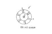
従来の大部分の燃料噴射器およびドーム・スワーラは旋回流を発生するため軸流スワーラ転向ベーン(図1Aおよび図1B)と半径流スワーラ転向ベーン(図2Aおよび図2B)のどちらかを利用する。図1Aおよび図1Bを参照すると、典型的には、フライス盤でスワーラ1の中心軸3に沿って直線状またはら線状輪郭形状に加工される、複数の転向ベーン2を備える軸流スワーラが示される。この転向ベーンは半径方向に向けて位置決めされ、スワーラ本体4の中心軸3周りに周方向に等間隔を保っている。転向ベーン2と内側/外側固定壁との間の領域は矢印で示される、気流の通路を形成する。半径流スワーラの主な特徴は通路内の気流がら旋方法でスワーラ本体4の中心軸3周りに旋回するように方向づけされることである。気流は通路と固定壁との間から流出すると、スワーラ本体4の中心軸3に対して鋭角で半径方向外側に膨張する。 Most conventional fuel injectors and dome swirlers use either an axial swirler turning vane (FIGS. 1A and 1B) or a radial swirl turning vane (FIGS. 2A and 2B) to generate a swirling flow. . With reference to FIGS. 1A and 1B, an axial flow swirler with a plurality of turning
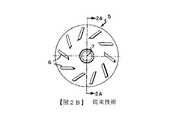
図2Aおよび図2Bを参照すると、半径流スワーラ5が示される。半径流スワーラ5のベーン配置は図1Aおよび図1Bに示される軸流スワーラ1のベーン配置と異なる。特に、半径流スワーラ5の転向ベーンのそれぞれのベースまたはベース部はスワーラ本体8の中心軸7に対して垂直である、鉛直面に配置される。この配置は(矢印で示されるように)気流が通路と固定壁内部をスワーラ本体8の半径方向内側中心軸7方向に流れるように方向づけされる。半径方向に向くベーン6を用いたとき、軸方向に気流を向けるため通常では偏向した流れまたは通路壁9を必要とする。 Referring to FIGS. 2A and 2B, a
他の代替的解決策を示す。たとえば、シモンらに付与された米国特許第4,842,197号明細書は燃焼室内に旋回流を引き起こす再循環流を用いて霧化燃料流を与える燃料噴射装置およびその方法を開示する。シモンらの装置は3つの同心状空気流を有する。最も内側の空気流と最も外側の空気流とは相反する方向に周方向の旋回を与える。中央の空気流は旋回しないで、軸方向に偏向させる、半径方向内側への気流を生じる。最も内側の空気流と中央の空気流とは燃料を霧化する。最も外側の空気流は安定した再循環域を形成する。 Other alternative solutions are shown. For example, U.S. Pat. No. 4,842,197 issued to Simon et al. Discloses a fuel injection apparatus and method for providing an atomized fuel stream using a recirculation flow that causes a swirl flow in a combustion chamber. The Simon et al. Device has three concentric airflows. The innermost airflow and the outermost airflow provide circumferential swirl in opposite directions. The central airflow does not swirl, but produces a radially inward airflow that deflects axially. The innermost air stream and the central air stream atomize the fuel. The outermost air flow forms a stable recirculation zone.
付言すれば、コブリッシらに付与された米国特許第5,144,804号明細書は冷機点火を改良するエアブラスト燃料ノズルを開示する。コブリッシらの燃料ノズルはノズル本体周りに周方向に間隔を置いて並ぶ空気入口スロットを有する内部空気旋回システムを備える。さらに、この空気入口スロットは効果的な空気旋回システムを提供する、テーパ状内側および外側区域を備える。 In addition, U.S. Pat. No. 5,144,804 to Kobrish et al. Discloses an air blast fuel nozzle that improves cold machine ignition. The Kobrish et al. Fuel nozzle includes an internal air swirl system having air inlet slots circumferentially spaced around the nozzle body. In addition, the air inlet slot comprises tapered inner and outer sections that provide an effective air swirl system.
従来技術のエア・スワーラ1、5のどれも満足の行く結果をもたらすが、軸流スワーラ1は燃料噴射器の場合、より広範に使用すべきであると思われる。軸流スワーラ1は単一のエアブラスト、純エアブラストおよび補助エアブラスト・ノズルのような普通の燃料噴射装置と容易に組み合わせることができる。これらはまた流体旋回運動を生じる、極めて小さい空気通路において使用するのに申し分なく適する。軸流スワーラ1における転向ベーン2の上流開口は通常流入気流と同じ方向に合わされ、それゆえ、転向ベーン2は気流をベーン通路に導くことで生じる半径流スワーラ5のような大きい圧力損失が発生することはない。 Although any of the prior
これに対して、半径流スワーラ5は複雑な配置と流体力学的転向ベーン6とを用いることなく、旋回流を発生する場合に極めて有効である。半径流スワーラ5は主として燃焼器ドームにおいて使用される。単純な直線状ベーン配置を用いるとき、半径流スワーラ5は流体力学的軌跡を持つ流れに由来する問題が生じる懸念が殆どなく、混合を通じて強い旋回を作り出す能力がある。 On the other hand, the
従来技術による軸流および半径流スワーラの主な不利な点とはスワーラを製造する手段と方法である。典型的には、軸流および半径流スワーラはCNCフライス盤によって製造される。この加工工程は低速回転もしくは輪郭加工モードでの一定の軌道または輪郭に沿って1度に1工具パスで材料を削り取る。この工程は極端に時間を浪費する。さらに、スワーラに高温で、硬さのある材料が必要であるとき、フライス工程は一段と時間を浪費し、通常切削工具の頻繁な交換によって工具コストが著しく増加する。今日の世界的市場では、自由競争になるため製造者は燃料噴射器および燃焼器ドームの製造コストを引き下げる新たな加工技術とスワーラ設計とを開発しなければならない。 The main disadvantage of prior art axial and radial flow swirlers is the means and method of manufacturing the swirler. Typically, axial and radial flow swirlers are manufactured by CNC milling machines. This machining process scrapes material in one tool pass at a time along a constant trajectory or contour in low speed rotation or contour machining mode. This process is extremely time consuming. Further, when the swirler requires high temperature and hardness material, the milling process is more time consuming and the tool cost is significantly increased by frequent replacement of the normal cutting tools. In today's global marketplace, manufacturers must develop new processing technologies and swirler designs that reduce the cost of manufacturing fuel injectors and combustor domes in order to be free to compete.
したがって、燃料噴射器および燃焼器ドームで使用するエア・スワーラを設計し、組み立てる新規な方法を提供することは望ましい。さらに、多重積層体として同時に多部品を組み立て、製造コストの削減を図る、より高精度で、より効率的な技術の使用を可能にする、新たなスワーラ配置を提供することは望ましい。最後に、燃料噴霧と燃焼性能とを改良するため円錐形スワーラの概念を取り入れる、燃料噴射器設計を提供することは望ましい。 Accordingly, it would be desirable to provide a new way of designing and assembling an air swirler for use with fuel injectors and combustor domes. Furthermore, it would be desirable to provide a new swirler arrangement that allows multiple components to be assembled at the same time as a multi-layered structure, reducing manufacturing costs and enabling the use of more accurate and more efficient technology. Finally, it would be desirable to provide a fuel injector design that incorporates the concept of a conical swirler to improve fuel spray and combustion performance.
本発明は燃料と空気とに旋回動作を与える、ガスタービン・エンジンで使用される燃料噴射器および燃焼器ドーム用の新規な円錐スワーラおよびその装置を製造する方法に関する。従来の軸流、半径流スワーラと異なり、開示される円錐形スワーラは円錐形本体に削成される複数のスロットを特徴とする。このスロットの輪郭と間隔とは流体流動域と旋回強さとに対する広範な要求に適応するため多くの異なる方法で構成され、配置される。本発明の円錐形スワーラは多様な形式の燃料噴射ノズルに申し分なく適合し、炭素の堆積領域を最小にするため正面表面積を減少させる。 The present invention relates to a novel conical swirler for a fuel injector and combustor dome used in a gas turbine engine that provides swirling motion to fuel and air, and a method of manufacturing the apparatus. Unlike conventional axial and radial flow swirlers, the disclosed conical swirler features a plurality of slots cut into the conical body. The slot profile and spacing are constructed and arranged in many different ways to accommodate the wide range of requirements for fluid flow zones and swirl strength. The conical swirler of the present invention is well suited to various types of fuel injection nozzles and reduces the frontal surface area to minimize carbon deposition area.
本発明の目的は円錐形本体部と、方向づけされた燃料またはガス流を与える、転向通路を形成する多重輪郭転向スロットとを備える流体スワーラを提供することである。好ましくは、この流体スワーラは以下に説明される工程で製造される。 It is an object of the present invention to provide a fluid swirler comprising a conical body portion and a multi-contour turning slot that forms a turning passage that provides directed fuel or gas flow. Preferably, the fluid swirler is manufactured by the process described below.
本発明の別の目的はスワーラ素材を準備し、スワーラ素材を同軸配置で配置し、スワーラ素材のそれぞれにスロット型を形成する工程を含む、エア・スワーラを製造する方法を提供することである。好ましくは、スワーラ素材は円錐形または円盤形である。より好ましくは、積層体に重ねて組み上げたスワーラ素材のそれぞれにスロット型が同時に形成されるように、スワーラ素材は積層体に重ねられる。 Another object of the present invention is to provide a method of manufacturing an air swirler comprising the steps of providing a swirler material, arranging the swirler material in a coaxial arrangement, and forming a slot shape on each of the swirler materials. Preferably, the swirler material is conical or disc-shaped. More preferably, the swirler material is stacked on the laminate so that a slot shape is simultaneously formed on each of the swirler materials assembled on the stack.
本発明の一様相はスワーラ素材にスロットを形成する好ましい方法がワイヤ放電加工(EDM)法であり、これによってスワーラ素材から材料を除去してスロット型を形成する。この工程はこれまでの製造方法を上回る大きいコスト削減をもたらし、ガスタービン・エンジン用途の燃料霧化と燃焼とを申し分なく果たすスワーラを製造することができる。 One aspect of the present invention is the wire electrical discharge machining (EDM) method, which is a preferred method of forming slots in the swirler blank, thereby removing the material from the swirler blank to form a slot mold. This process provides significant cost savings over previous manufacturing methods and can produce a swirler that performs well for fuel atomization and combustion for gas turbine engine applications.
本発明の別の目的は流体および/または空気流に旋回動作を生じまたは与えるいずれかの方法に使用できる、円錐形エアおよび/または燃料スワーラを備える、単一エアブラスト、2重オリフィス・エアブラストおよび/または純エアブラスト噴射器を提供することにある。 Another object of the present invention is a single air blast, dual orifice air blast with a conical air and / or fuel swirler that can be used in any manner that produces or imparts a swirling action on fluid and / or air flow. And / or providing a pure air blast injector.
したがって、一実施例において、本発明は霧化のために燃料を分配する燃料投入部と、霧化のために燃料吐出噴霧を与える燃料吐出部と、燃料吐出部の近くで圧縮ガスの霧化流体流を与える円錐スワーラとを備える燃料噴射器を提供する。この実施例に従って円錐形スワーラは燃料を霧化する回転動作と直後の燃料流の膨張とを生じるため隣り合う転向ベーンの間に圧縮ガスの流体流を半径方向内側に向ける多重気流通路を形成する、多重転向ベーンを備えるように構成され、配置される。 Accordingly, in one embodiment, the present invention provides a fuel input portion that distributes fuel for atomization, a fuel discharge portion that provides fuel discharge spray for atomization, and atomization of compressed gas near the fuel discharge portion. A fuel injector is provided that includes a conical swirler that provides fluid flow. In accordance with this embodiment, the conical swirler forms multiple airflow passages that direct the fluid flow of compressed gas radially inward between adjacent turning vanes to produce a rotational motion to atomize the fuel and an immediate expansion of the fuel flow. , Constructed and arranged with multiple turning vanes.
好ましくは、円錐形スワーラは外側円錐形スワーラの入口開口面積の少なくとも2倍のネック部面積を備えた開口を有するエア・キャップと熱シールドとの間に介装される。より好ましくは、エア・キャップはネック域の半径方向内側上流の先細部と、ネック域の半径方向外側下流の末広部とを与えるように構成され、配置される。 Preferably, the conical swirler is interposed between an air cap having an opening with a neck area at least twice the inlet opening area of the outer conical swirler and the heat shield. More preferably, the air cap is constructed and arranged to provide a taper radially inward upstream of the neck region and a divergent portion radially downstream of the neck region.
別の実施例において、本発明は霧化のために実質的に同心状燃料噴霧を与える多重燃料吐出部と、霧化のために圧縮ガスの流体流を実質的に同心状燃料噴霧に向けるスワーラ部とを備える燃料噴射器を開示する。 In another embodiment, the present invention provides a multiple fuel discharge that provides substantially concentric fuel spray for atomization, and a swirler that directs a fluid flow of compressed gas to the substantially concentric fuel spray for atomization. A fuel injector comprising a portion is disclosed.
さらに、別の実施例において、本発明は前膜部に燃料膜を与える、1個の燃料吐出部と、燃料膜を霧化する流体流を与えるスワーラ部とを備える燃料噴射器を開示する。好ましくは、燃料吐出部は燃料膜を霧化するため回転動作と直後の燃料流の膨張とを生じるため燃料膜の外側より実質的に流れ始める圧縮ガスの流体流を半径方向内側円錐形燃料膜方向に向ける円錐形スワーラを備える。 In yet another embodiment, the present invention discloses a fuel injector comprising a fuel discharge section that provides a fuel film to the front membrane section and a swirler section that provides a fluid flow that atomizes the fuel film. Preferably, the fuel discharge portion causes the fuel film to atomize and causes a rotational motion and expansion of the fuel flow immediately thereafter, so that the fluid flow of the compressed gas that starts to flow substantially from the outside of the fuel film is radially inner conical fuel film. With a conical swirler pointing in the direction.
さらに、別の実施例において、本発明は環状通路と、円錐形燃料膜を与えるように構成され、配置された環状の前膜オリフィスとを有する1個の燃料吐出部と、1個の燃料吐出部の半径方向内側に構成され、配置された内側空気通路と連通する第1の円錐形スワーラと、1個の燃料吐出部の半径方向外側に構成され、配置され、第1の円錐形スワーラと同心である、外側空気通路と連通する、第2の円錐形スワーラとを有するスワーラ部とを備える燃料噴射器を開示する。第1の円錐形スワーラは環状燃料前膜オリフィスの実質的に内側に空気流を導入し、第2の円錐形スワーラは実質的に円錐形燃料膜を実質的に取り囲む空気流を導入する。 In yet another embodiment, the present invention provides a fuel outlet having an annular passage and an annular front membrane orifice arranged and arranged to provide a conical fuel membrane, and a fuel discharge. A first conical swirler that is configured radially inward of the portion and communicates with the disposed inner air passage, and is configured and disposed radially outward of one fuel discharge portion, and the first conical swirler, A fuel injector is disclosed comprising a concentric swirler portion having a second conical swirler in communication with an outer air passage. The first conical swirler introduces an air flow substantially inside the annular fuel pre-membrane orifice and the second conical swirler introduces an air flow substantially surrounding the conical fuel membrane.
本発明の他の目的と利点とは添付の図面と説明とから当業者に明らかにされる。 Other objects and advantages of the present invention will become apparent to those skilled in the art from the accompanying drawings and description.
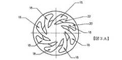
図3Aおよび図3Cを参照すると、本発明の第1の実施例に従う流体力学的転向スロット18を備える、軸流形円錐スワーラ10の実施例が開示される。以下の記述は円錐状または円錐形スワーラを説明するが、本発明はその原理が円盤形およびドーム形スワーラ素材(図示せず)についての加工も教示するので、円錐形スワーラに限定されない。製作された円錐スワーラ10は特定のスロット型が形成される、スワーラ素材11から始まる。このスロット型は複数の転向ベーン22と、隣り合う一対のベーン22を分離する、複数の転向スロット18とからなる。図3Aおよび図3Cは8個の転向ベーン22と、同数の8個の転向スロット18とを示しているが、本発明はスワーラ10が8個のスロット18および8個のベーン22よりも少ないまたはそれよりも多いスロットおよびベーンを備えることができるので、これに限定されない。図3Aおよび3Cはまたスロット18およびベーン22の寸法が一般に同じ大きさであることを示す。しかしながら、本発明はこの開示の範囲および発明の精神から離れないで、たとえば転向ベーン22の幅が転向スロット18の幅の2、3倍またはそれ以上に広くできるので、そのような同じ大きさに限定されない。 With reference to FIGS. 3A and 3C, an embodiment of an axial
スワーラ10の寸法は製造される燃料噴射器および燃焼器ドームの寸法と等しくなければならない。典型的には、製造されるスワーラ10の長さおよび厚さは約5.08mm(0.200インチ)から約10.16mm(0.400インチ)までの範囲であり、スワーラの外径は約12.85mm(0.500インチ)から約38.1mm(1.500インチ)までの範囲であり、スワーラの内径は約2.54mm(0.100インチ)から約20.32mm(0.800インチ)までの範囲である。 The size of the
一般に、スワーラが燃料噴射器あるいは燃焼器に使用されるとき、スワーラ10はエア・キャップと熱シールドとの間に配置される。スワーラ10はエア・キャップと熱シールドとの間に気密に装着しなければならない。このとき、転向ベーン22の内壁とエア・キャップおよび熱シールドの内面とは圧縮ガスが流動し、旋回するため方向づけされる気流通路の境界を形成するように取付けられる。 Generally, when the swirler is used in a fuel injector or combustor, the
図3Aおよび図3Cに示される軸流円錐スワーラ10は鋭角、すなわち90度よりも小さい内側スロット角φiと外側スロット角φoと与える転向ベーン22と、転向スロット18とを備える。この配置はより大きい旋回強さを与え、さらに円錐スワーラ10の半径方向内側中心軸方向に圧縮ガスを向ける。半径方向内側に旋回する圧縮ガスがスワーラ10の下流に達したとき、この高圧の混流ガスは燃料噴霧と十分に混ざるように半径方向外側に膨張する必要がある。せん断力が液状膜を微細な液滴へと砕き、外側への膨張が霧化した燃料液滴をより広い領域に分散する。結果として、霧化した燃料液滴が燃焼室(図示せず)に入ったとき、燃焼がより早く、より強く、クリーンになる。本発明の実施例は燃料分布を均一にし、ノズル前後の圧力損失をより小さくし、効率を向上する。The axial flow
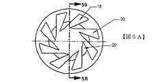
図5Aないし図5Cを参照すると、本発明に従う直線状側面の流体力学的転向スロット18を備える軸流円錐スワーラ10の代替的実施例が示される。図5Aないし図5Cに示される円錐スワーラ10は転向スロット18が曲線状ではなく、線形または実質的に直線状であることを除いて図3Aおよび図3Cに示される円錐スワーラ10と実質的に同一である。この配置は非直線状または曲線状転向スロット18を用いる場合よりも旋回強さは多分小さくなる。この線形または直線状スロットのためにこのスワーラの実施例は曲線状スロットを備えるスワーラと比べて機械加工時間をより短縮し、設計および製造をより効率的にする。 Referring to FIGS. 5A-5C, an alternative embodiment of an axial flow
図7Aおよび図7Bを参照すると、本発明に従う半径流形円錐スワーラ24の実施例が示される。好ましくは、この具体化された半径流スワーラ24の配置は旋回性能を落とすことなく、製造コストを大きく削減するため燃焼器ドームと共に使用することができる。この具体化された半径流形円錐スワーラ24は上述した軸流形円錐スワーラ10の基部ではなく、スワーラ24の外周部に配置される複数の吸入口25を備える。図7Aおよび図7Bは8個の吸入口25と、8個の転向ベーンとを示すが、本発明は8個よりも少ないまたはそれよりも多い吸入口25と転向ベーンとを備えることができるので、そのようなものに限定されない。 Referring to FIGS. 7A and 7B, an embodiment of a radial flow
例示的に示される吸入口25はそれと一致する複数の転向通路26を貫く非線形、すなわち曲線状の気流通路を与える。しかしながら、本発明は吸入口25が本発明の範囲と精神とから離れることなく、線形であることができるので、曲線状の気流通路に限定されない。流入する気流が実質的に半径方向から円錐スワーラ24の吸入口25に流入すると、この気流は流体力学的転向通路26を通り、吸入口方向に従って半径方向内側に向かって流れる。続いて、流動する気流は転向壁27に衝突して軸方向または実質的に軸方向に転向または偏向して流れる。 The illustrated
軸流形、半径流形円錐スワーラの幾つかの実施例を説明したが、ここで、複数の円錐エア・スワーラを製造する好ましい方法について説明する。この議論を通じて素材は「円錐形」として呼ばれるが、本発明はエア・スワーラ素材が円盤形またはドーム形であることが可能であり、そのような円錐形に限定されない。 Having described several embodiments of axial and radial flow conical swirlers, a preferred method of manufacturing a plurality of conical air swirlers will now be described. Throughout this discussion, the material is referred to as “conical”, but the present invention allows the air swirler material to be disk-shaped or dome-shaped and is not limited to such cones.
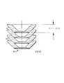
製造工程の最初の工程は後に続く機械加工のために複数の円錐形素材を加工することである。円錐形スワーラ素材11の実施例の側面図が図3Bに示される。このスワーラ素材11は内面12と外面14とを備える。スワーラ素材11の内面および外面12、14は必ずしも互いに平行でなくてもよいが、好ましくは、一般には、円錐形を与える、スワーラ素材11の平面16は転向スロット18の上流開口のために用意される。この平面16は一般に流入する流体流動に垂直または実質的に垂直方向に構成され、配置される。しかしながら、本発明の別の形態では、平面は僅かに傾斜角を付けて構成され、配置されてもよい。 The first step in the manufacturing process is to process a plurality of conical blanks for subsequent machining. A side view of an embodiment of the conical swirler blank 11 is shown in FIG. 3B. The swirler material 11 includes an
第2の工程はスワーラ素材11に備えられる2次元スロット型を決定することである。図3Aおよび図3Cは望ましい流動通路を形成するためスワーラ素材11に構成されるスロット型18の正面図および斜視図をそれぞれ示す。このスロット型18は風車に厳密に似ている、8個の流体力学的輪郭を有する。スロット型18は8個のスロットと8個の転向ベーンとを備えるが、スロット18と転向ベーン22の数は8個よりも多くまたは少なくすることができる。 The second step is to determine the two-dimensional slot type provided in the swirler material 11. 3A and 3C show a front view and a perspective view, respectively, of the
スロット型18は円錐スワーラ10の性能を決定する。したがって、幾つかのキー・パラメータが設計上の考察のために評価されることが重要である。図4を参照すると、重要なスロット・パラメータは内側オフセット距離ri、外側オフセット距離ro、内側半径Ri、外側半径Ro、内側スロット角φi、外側スロット角φoおよび絞りギャップABを含む。スロット18の輪郭と形状とによりこれらのパラメータは相互に関係し、スワーラ性能に異なる影響を及ぼす。たとえば、オフセット距離は流体流動の旋回強さに強い影響を与えるように現れる。特に、オフセット距離が長くなればなる程、旋回強さはより強くなる。しかし、内側半径Riがより小さくなると、旋回強さは減少する傾向があり、さらに、噴霧角度がより狭くなる。予測したことに反して、スロット18と関係する輪郭形状と旋回強さとが流動面積に関与するで、絞りギャップABが小さくなっても、スワーラ10の有効流動面積は必ずしも小さくなるとは限らない。一般に、流体力学的形状のスロット型18は直線状のスロット18よりも高い転向効率を与える。The
上記の設計指針とパラメータとを用いて当業者は広範なスワーラと流動範囲に対する要求を満たすため異なる多くの方法で2次元切削型を配置することができる。たとえば、図5Aないし図5Cは直線状切削面を備える転向ベーン22を利用する、単純なスロット型18の第2の実施例の外観を示す。この直線状側面配置はスワーラの性能を落とすことなく、製造を容易にする。 Using the above design guidelines and parameters, one of ordinary skill in the art can place a two-dimensional cutting die in many different ways to meet the requirements for a wide range of swirlers and flow ranges. For example, FIGS. 5A-5C show the appearance of a second embodiment of a
第3の工程では、いったんスロット型18が決定したならば、スワーラ素材11の輪郭スロット18から材料を除去する。新たな円錐スワ−ラ10は従来からのCNC、フライス加工、鋳造、レーザ加工、光化学エッチングおよびこれらの技術の組み合わせを含む、異なる多くの加工技術を用いて製造することができる。好ましくは、当業者によく知られたEDM加工機およびEDM法を用いてスワーラ素材11から材料を除去する。 In the third step, once the
手短にいえば、ワイヤEDM法は電気的導体のワーク、すなわちスワーラ素材11と電極(図示せず)との間に発生させるスパークを利用する。絶縁液、たとえば脱イオン水とオイルとをワークと電極とを隔て、加工くずを流すために供給する。 In short, the wire EDM method uses an electric conductor work, that is, a spark generated between a swirler material 11 and an electrode (not shown). An insulating liquid, such as deionized water and oil, is supplied to separate the workpiece and the electrode in order to allow processing waste to flow.
ワークの一部を溶融し、蒸発させるスパークは極めて高温で発生する。細いワイヤ電極を用いてEDM法は他の機械加工法に固有の制限条件を伴わず高品質で、高精度な部品を加工することができる。この方法では、材料を除去して入口開口20と曲線状転向ベーン22とを形成する。 Sparks that melt and evaporate part of the work occur at very high temperatures. Using a thin wire electrode, the EDM method can process high-quality and high-precision parts without the limitations inherent in other machining methods. In this method, material is removed to form an
ワイヤEDM法は新たな円錐スワーラ10を製作するため明らかに多くの利点を提供する。複雑な曲線形状を作り出すことは理想的であり、設計者が多様な用途のために異なる多くの方法でスロットを配置することを可能にする。さらに、この方法はステンレス鋼および合金鋼を加工するため熱処理材、超硬材、高靭性材を含む、特殊材料を扱うことができる。ワイヤEDMは±0.025mm(0.001インチ)以下か、より厳密な値の許容差をを容易に維持することができる。通常、精度および一貫性は数量と関係なく、各スワーラ部品に維持することができる。さらに、従来のフライス加工と相違してワイヤEDM法で製造された部品はバリがなく、莫大な労働コストを省くことができる。この加工法は材料にいかなる応力も生じさせないので、スワーラ部品は加工後に反り、弓状変形、曲がりを生じない。 The wire EDM method clearly offers many advantages for fabricating a new
しかしながら、ワイヤEDM法の最も重要な特徴は同時に多くの部品の組み立てを可能にする円錐スワーラ素材11を積層する、すなわち共に重ねることができる点にある。積層スワーラ10と自動コンピュータ制御との組み合わせによりワイヤEDM法は本発明で述べた円錐スワーラを製作する最も効率的で、経済的な選択となる。 However, the most important feature of the wire EDM method is that conical swirler blanks 11 that allow the assembly of many parts at the same time can be laminated, i.e. stacked together. The combination of the
好ましくは、図6に示されるように、加工前に複数のスワーラ素材11を積層体60として重ねる。スワーラ素材11は互いの上面に積み重ね、ワイヤEDM法工程の間、固定具(図示せず)によって共に固定される。同時に組み立てられるスワーラ素材11の数は個々のスワーラ素材11の長さに左右される。好ましい実施例において、高能率、高速ワイヤEDM法の場合、積層されるスワーラ素材11の全長は約50.8mm(2インチ)を超えない値でなければならない。典型的なスワーラ素材11の長さは約5.08mm(0.200インチ)から約10.16mm(0.400インチ)のまでの範囲にある。したがって、約5.08mm(0.200インチ)の長さを有するスワーラ素材11の場合、各ワイヤEDM製造操作は最低1個の積層体60で同時に少なくとも10個の完成円錐スワーラ10を製作することができる。 Preferably, as shown in FIG. 6, a plurality of swirler materials 11 are stacked as a
当業者は1度に加工できるスワーラ素材の数がEDM加工機の能力に左右されることを容易に理解する。また、1度に共に積層され、加工される円錐スワーラの数が積層円錐スワーラの重なり具合を定めるスワーラ素材の円錐ピッチに左右されることを理解する。 Those skilled in the art will readily understand that the number of swirler materials that can be processed at a time depends on the capabilities of the EDM machine. It will also be appreciated that the number of conical swirlers that are stacked and processed together at one time depends on the conical pitch of the swirler material that defines the overlap of the stacked conical swirlers.
最も重要な点として積層体60から作られた各円錐スワーラ10の完成品は品質にバラツキがなく、厳密に同じ寸法を有する。スワーラが後にバリ取り、再加工、検査および較正のような幾つかの操作を省略するので、精密で、一貫した寸法はコスト削減に極めて重要である。 Most importantly, the finished product of each
ワイヤEDM法は円錐形スワーラ10を製造するため理想的であるが、これは半径流円盤形スワーラ24を製作するためにも適する。 The wire EDM method is ideal for producing the
円錐スワーラ10を使用する燃料噴射器について説明する。円錐スワーラ10を開発する主要な目的の一つはコスト削減のためにスワーラを燃料噴射器に組み込むことである。円錐形スワーラ10は製造コストを下げるワイヤEDM法を使用するだけでなく、この円錐形スワーラを円錐面を備える実在す大部分の燃料噴射器配置に申し分なく適合させることである。運転において、円錐スワーラ10が燃料噴射器のエア・スワーラとして用いられるとき、圧縮空気は開口20を通って転向スロットに流入する。気流は圧力の作用のもとで転向ベーン22の側壁と内面12および外面14固定壁とで形成される転向通路に偏向して流れる。この気流の旋回強さはオフセット距離と出口域の転向角度とによって決定される。 A fuel injector using the
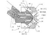
図8は2重オリフィス・エアブラスト噴射器28に適合する円錐エア・スワーラ40の実施例を示す。この具体化された2重オリフィス・エアブラスト噴射器28は2つの燃料回路、すなわち主燃料回路30と補助燃料回路32とを備える。主燃料回路30を通って流れる燃料はオリフィス36から吹き出し、主噴霧を発生する。同様に、補助燃料回路32を通って流れる燃料は同心状補助噴霧を形成するように環状オリフィス38から吹き出す。各燃料回路は同種かまたは異なる燃料を受け入れることができる。異なる燃料を受け入れることにより異なるエンジン用途および空燃混合気に応じて変えられる燃料噴射器28の噴霧特性に合わせることができる。 FIG. 8 shows an embodiment of a
好ましくは、円錐エア・スワーラ40はエア・キャップ42と熱シールド44との間に位置決めされる。霧化気流が開口46を通ってエア・スワーラ40に流入し、転向ベーン48によって形成される転向通路を経て中心軸方向に流れる。気流が噴射器28から出たとき、気流は主噴霧と補助噴霧とから与えられる燃料液滴を円型または実質的に円型に分散するため半径方向外方向に膨張する。 Preferably, the
具体化されたエア・ブラスト燃料噴射器28の円錐スワーラ40の性能は実験テストによってエア・キャップ42の形状と効果的に関連付けられる。特に、ネック点52の出口面50の輪郭形状と直径寸法とは液滴サイズ、噴霧角度、旋回強さ、流速および噴霧型のような噴霧特性を決定する際に重要な役割を果たす。 The performance of the embodied
エア・キャップ42の出口面50の好ましい輪郭形状は燃料出口オリフィス36から短い距離で配置されるネック点52と共に滑らかな先細−末広配置である。「先細−末広配置」とはネック点52から上流が半径方向内側円錐スワーラ40方向に先細形になり、ネック点52から下流が半径方向外側燃焼室(図示せず)方向に末広形になる配置を称する。気流通路を出た後、円錐スワーラ40から流出した旋回空気は初めにエア・キャップ42の半径方向内側の先細部に流入する。結果として、この出口気流は旋回をより大きくし、霧化をより良好にするオリフィス30と環状オリフィス38の方向に向く。次いで、霧化燃料はネック点52を通ってエア・キャップ42の半径方向外側の末広部に流入し、燃焼室に流入したとき、半径方向外側に分散する。 The preferred profile of the
好ましくは、ネック点52の直径はスワーラ通路に入る気流に過度の圧縮を強いることのないように十分に大きい出口面積を与えるべきである。一般に、ネック点52の好ましい流動面積はスワーラ入口有効開口域46の面積の少なくとも2倍にすべきである。 Preferably, the diameter of the
図9は単一回路式単一エアブラスト噴射器60に適合する、複数の円錐スワーラ62、64からなる実施例を示す。この実施例において、燃料噴射器60は空気流回路用円錐スワーラ64と燃料流回路用円錐スワーラ62とを備える。単一回路式単一エアブラスト噴射器60は燃料霧化および液滴分散のために旋回動作を引き起こす円錐燃料スワーラ62と円錐エア・スワーラ64とを利用する。 FIG. 9 shows an embodiment consisting of a plurality of
圧力の作用のもとで液体燃料は燃料回路66を通って燃料スワーラ62の開口68に流れる。この液体燃料が燃料スワーラ62の転向通路から出たとき、旋回室70内の燃料に回転流が発生する。回転する液体燃料は微細な燃料液滴を含む、中空噴霧として旋回室70のオリフィス72を流出する。 Under the action of pressure, the liquid fuel flows through the
気流側について、圧縮空気はエア・スワーラ64の開口74に流入する。転向ベーンは気流を半径方向内側に向ける。気流がエア・スワーラ64の気流通路を出たとき、気流は初めにエア・キャップの半径方向内側の先細部に流入する。結果として、この出口気流は燃料噴霧の方向に向かい旋回をより大きくし、霧化をより良好にするオリフィス72を流出する。燃料噴霧と旋回空気との素早い混合と霧化とは霧化噴霧が半径方向外方向に燃料域に分散する前に、ネック域76付近で起こる。 On the airflow side, the compressed air flows into the
図10は前膜エアブラスト噴射器80に適合する複数の円錐スワーラ82、88からなる、さらに別の実施例を示す。この特定の実施例において、内側エア・スワーラ82は燃料噴射器80の中央通路84に環状燃料オリフィス86の上流にそれと幾分かの距離を置いて配置される。外側スワーラ88はエア・キャップと熱シールド本体90の外面との間に配置される。好ましくは、内側エア・スワーラ82と外側エア・スワーラ88とは同心である。 FIG. 10 shows yet another embodiment comprising a plurality of
燃料スワーラ92は燃料分配系統94に接続される。燃料はら旋通路を通って複数の回転スロット98に分れて流れる、燃料分配系統94を通って燃料スワーラ92に流動する。燃料は回転スロット98を通り、環状燃料通路100に流動する。燃料は環状燃料通路100からエア・キャップの半径方向内側の先細部に中空シート状に放出される前に、初めに前膜域102に流入し、前膜域102の壁面に付着する、。 The fuel swirler 92 is connected to the
圧縮ガスは外側エア・スワーラ88の開口に流入し、それと同時に、内側エア・スワーラ82の開口に入る前に、中央通路84を通って流動する。中心軸周りに同心に構成され、配置される内側および外側エア・スワーラ82、88はそれぞれ気流を半径方向内側中心軸方向に向ける転向ベーンを備える。内側エア・スワーラ82は中空燃料シート内側のエア・キャップの半径方向内側の先細部に入る、内側空気流104を発生する。外側エア・スワーラ88は中空燃料シート外側のエア・キャップの半径方向内側の先細部に入る、外側空気流106を発生する。内側空気気流104と外側空気流106との合流気流は中空燃料シートに衝突し、燃料シートを砕いて液滴を望ましい噴霧型に分散する。霧化噴霧はエア・キャップの半径方向外側の末広部に流動し、霧化噴霧を半径方向外方向の燃焼域に分散させる。 The compressed gas flows into the opening of the
本発明の好ましい実施例が特定の用語を用いて説明されたが、この説明は具体例について説明のみを目的としたものであり、変更および変形が添付の請求の範囲に記載の発明の精神および範囲から離れることなく、なし得ることは理解されるべきである。 While preferred embodiments of the invention have been described using specific terms, the description is intended for purposes of illustration only, and modifications and variations are intended to be within the spirit and scope of the invention as set forth in the appended claims. It should be understood that it can be done without departing from the scope.
10、24、40… 円錐スワーラ
11… スワーラ素材
18… 転向スロット
22… 転向ベーン
42… エア・キャップ
60… 積層体
62… 円錐燃料スワーラ
64… 円錐エア・スワーラ
82… 内側エア・スワーラ
88… 外側エア・スワーラ10, 24, 40 ... Conical swirler 11 ...
Claims (27)
Translated fromJapaneseb)前記1個ないしそれ以上のスワーラ素材を同軸方法で配置し、
c)前記1個ないしそれ以上のスワーラ素材のそれぞれにスロット型を形成する
工程を含む、エア・スワーラを製造する方法。a) Prepare one or more swirler materials,
b) arranging the one or more swirler materials in a coaxial manner;
c) A method of manufacturing an air swirler, comprising the step of forming a slot mold in each of the one or more swirler materials.
a)霧化のために燃料を分配する燃料投入部と、
b)霧化のために燃料吐出噴霧を与える燃料吐出部と、
c)前記燃料吐出部の近くで圧縮ガスの霧化流体流を与える、少なくとも1個の円錐形スワーラと
を備え、前記少なくとも1個の円錐形スワーラが燃料を霧化する旋回動作と直後の燃料流の膨張とを生じるため隣り合う転向ベーンの間に前記圧縮ガスの流体流を半径方向内側に向ける複数の気流通路が形成される、間隔を置いて並ぶ複数の転向ベーンを備えるように、構成され、配置されてなる燃料噴射器。A fuel injector that mixes fuel and compressed gas, and supplies a mixed fuel atomized with the compressed gas to the combustion chamber,
a) a fuel input section for distributing fuel for atomization;
b) a fuel discharge section for providing fuel discharge spray for atomization;
c) at least one conical swirler that provides an atomized fluid flow of compressed gas near the fuel discharge, wherein the at least one conical swirler atomizes fuel and immediately following fuel A plurality of diverting vanes arranged at spaced intervals, wherein a plurality of air flow passages are formed between adjacent diverting vanes to cause fluid flow of the compressed gas to radially inward in order to cause flow expansion; And a fuel injector.
a)霧化のために複数の同心状燃料噴霧を与えるように構成され、配置された複数の燃料吐出部と、
b)霧化のために前記複数の同心状燃料噴霧に圧縮ガスの流れを向けるように構成され、配置されたスワーラ部と
を備え、前記複数の燃料吐出部は独立して作動し、燃料回路と燃料分配系統とを連絡している、同心状2重オリフィスを有し、前記スワーラ部は前記燃料噴霧を霧化する旋回動作と直後の燃料流の膨張とを生じるため隣り合う転向ベーンの間に圧縮ガスの流体流を半径方向内側の複数の同心状燃料噴霧方向に向ける複数の気流通路が形成される、間隔を置いて並ぶ複数の転向ベーンを備えるように、構成され、配置される円錐形スワーラを備える燃料噴射器。A fuel injector that mixes fuel and compressed gas, and supplies a mixed fuel atomized with the compressed gas to the combustion chamber,
a) a plurality of fuel outlets configured and arranged to provide a plurality of concentric fuel sprays for atomization;
b) a swirler portion arranged and arranged to direct a flow of compressed gas to the plurality of concentric fuel sprays for atomization, the plurality of fuel discharge portions operating independently, and a fuel circuit Between the adjacent turning vanes to cause a swirling action to atomize the fuel spray and an expansion of the fuel flow immediately after that. A cone configured and arranged with a plurality of spaced-apart diverting vanes formed with a plurality of airflow passages for directing a fluid flow of compressed gas in a plurality of concentric fuel spray directions radially inward Fuel injector equipped with a swirler.
a)前膜部に燃料膜を与えるように構成され、配置された少なくとも1個の燃料吐出部と、
b)前記燃料膜に霧化ガス流を与えるように構成され、配置されたスワーラ部と
を備え、前記燃料吐出部は円錐形燃料膜を与える円錐形燃料スワーラを備え、前記スワーラ部は燃料膜を霧化する回転動作と直後の燃料流の膨張とを生じるため隣り合う転向ベーンの間に前記燃料膜の外側より流れ始める圧縮ガスの流体流を前記半径方向内側円錐形燃料膜方向に向ける複数の気流通路が形成される、間隔を置いて並ぶ複数の転向ベーンを備えるように構成され、配置される円錐形スワーラを備えてなる燃料噴射器。A fuel injector that mixes fuel and compressed gas, and supplies a mixed fuel atomized with the compressed gas to the combustion chamber,
a) at least one fuel discharge portion configured and arranged to impart a fuel film to the front membrane portion;
b) a swirler portion configured and arranged to provide an atomized gas flow to the fuel film, the fuel discharge portion including a conical fuel swirler that provides a conical fuel film, and the swirler portion is a fuel film A plurality of compressed gas fluid flows that start to flow from the outside of the fuel film between adjacent turning vanes in order to cause the rotation operation to atomize the fuel and the expansion of the fuel flow immediately thereafter, toward the radially inner conical fuel film A fuel injector comprising a conical swirler configured and arranged with a plurality of diverting vanes arranged at spaced intervals, wherein an airflow passage is formed.
a)環状通路と、円錐形燃料膜を与えるように構成され、配置された環状の前膜オリフィスとを有する1個の燃料吐出部と、
b)前記1個の燃料吐出部の半径方向内側に構成され、配置された内側空気通路と連通する第1の円錐形スワーラと、前記1個の燃料吐出部の半径方向外側に構成され、配置され、前記第1の円錐形スワーラと同心である、外側空気通路と連通する、第2の円錐形スワーラとを有するスワーラ部と
を備え、前記スワーラ部の前記第1および第2の円錐形スワーラは前記燃料膜と前記環状燃料前膜オリフィスとに流体流を与えるように構成され、配置され、前記第1の円錐形スワーラは前記環状燃料前膜オリフィスの半径方向内側に空気流を導入し、前記第2の円錐形スワーラは前記円錐形燃料膜を取り囲む空気流を導入する燃料噴射器。A fuel injector that mixes fuel and compressed gas, and supplies a mixed fuel atomized with the compressed gas to the combustion chamber,
a) a fuel discharge having an annular passage and an annular front membrane orifice configured and arranged to provide a conical fuel membrane;
b) A first conical swirler that is configured radially inside the one fuel discharge portion and communicates with the arranged inner air passage, and is configured and arranged radially outside the one fuel discharge portion. A swirler portion having a second conical swirler in communication with an outer air passage that is concentric with the first conical swirler, and wherein the first and second conical swirlers of the swirler portion Is configured and arranged to provide a fluid flow to the fuel membrane and the annular fuel pre-membrane orifice, the first conical swirler introduces an air flow radially inward of the annular fuel pre-membrane orifice; The second conical swirler is a fuel injector for introducing an air flow surrounding the conical fuel film.
a)円錐形本体部と、
b)複数の輪郭転向スロットと
を備え、前記各複数の輪郭転向スロットは内側壁面と外側壁面とを有する転向ベーンを備え、前記一の転向ベーンの内側壁面と隣接する転向ベーンの外側壁面とが両壁面の間に転向通路を形成している流体スワーラ。A fluid swirler produced by the process of claim 1 having a central axis for providing at least one fuel or gas stream,
a) a conical body,
b) a plurality of contour turning slots, each of the plurality of contour turning slots comprising a turning vane having an inner wall surface and an outer wall surface, and an inner wall surface of the one turning vane and an outer wall surface of the adjacent turning vane A fluid swirler that forms a turning passage between both wall surfaces.
25. The fluid swirler of claim 24, wherein the plurality of contour turning slots comprise outlet openings that direct fluid flow at a radial offset distance from the central axis.
Applications Claiming Priority (1)
| Application Number | Priority Date | Filing Date | Title |
|---|---|---|---|
| US10/864,211US8348180B2 (en) | 2004-06-09 | 2004-06-09 | Conical swirler for fuel injectors and combustor domes and methods of manufacturing the same |
Publications (1)
| Publication Number | Publication Date |
|---|---|
| JP2005351614Atrue JP2005351614A (en) | 2005-12-22 |
Family
ID=34934473
Family Applications (1)
| Application Number | Title | Priority Date | Filing Date |
|---|---|---|---|
| JP2005153739APendingJP2005351614A (en) | 2004-06-09 | 2005-05-26 | Fuel atomizer, conical swirler for combustor dome, and manufacturing method thereof |
Country Status (3)
| Country | Link |
|---|---|
| US (2) | US8348180B2 (en) |
| EP (1) | EP1605204B1 (en) |
| JP (1) | JP2005351614A (en) |
Cited By (1)
| Publication number | Priority date | Publication date | Assignee | Title |
|---|---|---|---|---|
| JP2010216668A (en)* | 2009-03-13 | 2010-09-30 | Kawasaki Heavy Ind Ltd | Gas turbine combustor |
Families Citing this family (71)
| Publication number | Priority date | Publication date | Assignee | Title |
|---|---|---|---|---|
| US8348180B2 (en)* | 2004-06-09 | 2013-01-08 | Delavan Inc | Conical swirler for fuel injectors and combustor domes and methods of manufacturing the same |
| US7237730B2 (en)* | 2005-03-17 | 2007-07-03 | Pratt & Whitney Canada Corp. | Modular fuel nozzle and method of making |
| DE102006004068A1 (en)* | 2006-01-28 | 2007-08-09 | Fisia Babcock Environment Gmbh | Method and device for mixing a fluid with a large gas flow rate |
| EP2072895B1 (en) | 2007-12-18 | 2014-07-23 | Electrolux Home Products Corporation N.V. | Gas burner with improved primary air duct |
| US8528334B2 (en)* | 2008-01-16 | 2013-09-10 | Solar Turbines Inc. | Flow conditioner for fuel injector for combustor and method for low-NOx combustor |
| US7988074B2 (en)* | 2008-03-05 | 2011-08-02 | J. Jireh Holdings Llc | Nozzle apparatus for material dispersion in a dryer and methods for drying materials |
| ATE540265T1 (en)* | 2009-04-06 | 2012-01-15 | Siemens Ag | SWIRL DEVICE, COMBUSTION CHAMBER AND GAS TURBINE WITH IMPROVED SWIRL |
| US20120102736A1 (en)* | 2009-09-02 | 2012-05-03 | Turbulent Energy Llc | Micro-injector and method of assembly and mounting thereof |
| US8375548B2 (en)* | 2009-10-07 | 2013-02-19 | Pratt & Whitney Canada Corp. | Fuel nozzle and method of repair |
| DE102011075409A1 (en)* | 2011-05-06 | 2012-11-08 | Wolf Gmbh | Mixing system for modulating burner and swirl body for mixing system |
| RO127544A0 (en)* | 2011-05-09 | 2012-06-29 | Iosif Ursuţ | Process for achieving total combustion by using injectors and injectors |
| US20140339339A1 (en)* | 2011-11-03 | 2014-11-20 | Delavan Inc | Airblast injectors for multipoint injection and methods of assembly |
| US9188063B2 (en) | 2011-11-03 | 2015-11-17 | Delavan Inc. | Injectors for multipoint injection |
| US9631560B2 (en)* | 2011-11-22 | 2017-04-25 | United Technologies Corporation | Fuel-air mixture distribution for gas turbine engine combustors |
| EP2687808A1 (en)* | 2012-07-18 | 2014-01-22 | Airbus Operations GmbH | Homogenisation device, heat exchanger assembly and method of homogenising a temperature distribution in a fluid stream |
| CN102862031B (en)* | 2012-09-26 | 2014-10-08 | 北京理工大学 | Forming method of rotatably overlaying swirler |
| US9400104B2 (en)* | 2012-09-28 | 2016-07-26 | United Technologies Corporation | Flow modifier for combustor fuel nozzle tip |
| DE112013006294B4 (en)* | 2012-12-27 | 2019-06-27 | Luxnara Yaovaphankul | Device for generating a turbulent flow of a fluid |
| GB201303428D0 (en)* | 2013-02-27 | 2013-04-10 | Rolls Royce Plc | A vane structure and a method of manufacturing a vane structure |
| US10161633B2 (en)* | 2013-03-04 | 2018-12-25 | Delavan Inc. | Air swirlers |
| JP2014173479A (en)* | 2013-03-08 | 2014-09-22 | Hitachi Automotive Systems Ltd | Fuel injection valve |
| US10228137B2 (en)* | 2013-08-30 | 2019-03-12 | United Technologies Corporation | Dual fuel nozzle with swirling axial gas injection for a gas turbine engine |
| WO2015069354A2 (en)* | 2013-08-30 | 2015-05-14 | United Technologies Corporation | Dual fuel nozzle with liquid filming atomization for a gas turbine engine |
| US9388983B2 (en)* | 2013-10-03 | 2016-07-12 | Plum Combustion, Inc. | Low NOx burner with low pressure drop |
| JP6433162B2 (en)* | 2014-02-12 | 2018-12-05 | 株式会社エンプラス | Nozzle plate for fuel injector |
| CN103900106B (en)* | 2014-03-11 | 2015-08-12 | 哈尔滨工程大学 | A kind of dual fuel nozzle of plasma-catalytic fuel gas |
| US20150285502A1 (en)* | 2014-04-08 | 2015-10-08 | General Electric Company | Fuel nozzle shroud and method of manufacturing the shroud |
| FR3022985B1 (en)* | 2014-06-25 | 2019-06-21 | Safran Aircraft Engines | INJECTION SYSTEM FOR TURBOMACHINE COMBUSTION CHAMBER CONFIGURED FOR DIRECT INJECTION OF TWO COAXIAL FUEL TANKS |
| US10252270B2 (en)* | 2014-09-08 | 2019-04-09 | Arizona Board Of Regents On Behalf Of Arizona State University | Nozzle apparatus and methods for use thereof |
| US9901944B2 (en) | 2015-02-18 | 2018-02-27 | Delavan Inc | Atomizers |
| US9897321B2 (en) | 2015-03-31 | 2018-02-20 | Delavan Inc. | Fuel nozzles |
| US10385809B2 (en) | 2015-03-31 | 2019-08-20 | Delavan Inc. | Fuel nozzles |
| KR101692347B1 (en)* | 2015-04-17 | 2017-01-03 | 주식회사 에스엠뿌레 | Sprayer and spray control apparatus |
| US10041676B2 (en) | 2015-07-08 | 2018-08-07 | General Electric Company | Sealed conical-flat dome for flight engine combustors |
| GB2543803B (en)* | 2015-10-29 | 2019-10-30 | Rolls Royce Plc | A combustion chamber assembly |
| US10047959B2 (en) | 2015-12-29 | 2018-08-14 | Pratt & Whitney Canada Corp. | Fuel injector for fuel spray nozzle |
| US10288292B2 (en) | 2016-01-15 | 2019-05-14 | Delavan Inc | Swirlers |
| US11020758B2 (en)* | 2016-07-21 | 2021-06-01 | University Of Louisiana At Lafayette | Device and method for fuel injection using swirl burst injector |
| US10876477B2 (en) | 2016-09-16 | 2020-12-29 | Delavan Inc | Nozzles with internal manifolding |
| US10837640B2 (en) | 2017-03-06 | 2020-11-17 | General Electric Company | Combustion section of a gas turbine engine |
| US11131459B2 (en) | 2017-09-26 | 2021-09-28 | Delavan Inc. | Combustor with an air mixer and an air swirler each having slots |
| GB201803650D0 (en)* | 2018-03-07 | 2018-04-25 | Rolls Royce Plc | A lean burn fuel injector |
| US10788214B2 (en)* | 2018-04-10 | 2020-09-29 | Delavan Inc. | Fuel injectors for turbomachines having inner air swirling |
| CN108412643B (en)* | 2018-06-08 | 2024-02-13 | 哈尔滨工业大学 | Vaporization mechanism |
| CN108722703B (en)* | 2018-07-12 | 2024-01-26 | 中国石油大学(北京) | Reverse spray type washing nozzle |
| US11255543B2 (en) | 2018-08-07 | 2022-02-22 | General Electric Company | Dilution structure for gas turbine engine combustor |
| US11268447B2 (en) | 2018-09-12 | 2022-03-08 | Pratt & Whitney Canada Corp. | Igniter for gas turbine engine |
| US11255271B2 (en) | 2018-09-12 | 2022-02-22 | Pratt & Whitney Canada Corp. | Igniter for gas turbine engine |
| US11415060B2 (en) | 2018-09-12 | 2022-08-16 | Pratt & Whitney Canada Corp. | Igniter for gas turbine engine |
| US11286861B2 (en) | 2018-09-12 | 2022-03-29 | Pratt & Whitney Canada Corp. | Igniter for gas turbine engine |
| US11391212B2 (en) | 2018-09-12 | 2022-07-19 | Pratt & Whitney Canada Corp. | Igniter for gas turbine engine |
| US11454173B2 (en) | 2018-09-12 | 2022-09-27 | Pratt & Whitney Canada Corp. | Igniter for gas turbine engine |
| US11391213B2 (en) | 2018-09-12 | 2022-07-19 | Pratt & Whitney Canada Corp. | Igniter for gas turbine engine |
| US11408351B2 (en) | 2018-09-12 | 2022-08-09 | Pratt & Whitney Canada Corp. | Igniter for gas turbine engine |
| US11401867B2 (en) | 2018-09-12 | 2022-08-02 | Pratt & Whitney Canada Corp. | Igniter for gas turbine engine |
| US11268486B2 (en) | 2018-09-12 | 2022-03-08 | Pratt & Whitney Canada Corp. | Igniter for gas turbine engine |
| US11534728B2 (en)* | 2018-11-15 | 2022-12-27 | Caterpillar Inc. | Reductant nozzle with helical channel design |
| US10557630B1 (en) | 2019-01-15 | 2020-02-11 | Delavan Inc. | Stackable air swirlers |
| CN110193285B (en)* | 2019-07-12 | 2024-06-21 | 中电华创(苏州)电力技术研究有限公司 | Ammonia injection mixed flow device of SCR denitration system |
| JP7161152B2 (en)* | 2019-10-23 | 2022-10-26 | 株式会社Ihi | liquid fuel injector |
| RU207311U1 (en)* | 2020-12-15 | 2021-10-22 | Федеральное государственное бюджетное образовательное учреждение высшего образования "Воронежский государственный технический университет" (ВГТУ) | Vortex gunning nozzle |
| US11679994B2 (en)* | 2021-04-01 | 2023-06-20 | Micronic Technologies, Inc. | Atomizer for use in water treatment and method for its use |
| GB2607012B (en)* | 2021-05-20 | 2024-01-17 | Caterpillar Energy Solutions Gmbh | Gas Mixer |
| US11906165B2 (en)* | 2021-12-21 | 2024-02-20 | General Electric Company | Gas turbine nozzle having an inner air swirler passage and plural exterior fuel passages |
| US12072099B2 (en) | 2021-12-21 | 2024-08-27 | General Electric Company | Gas turbine fuel nozzle having a lip extending from the vanes of a swirler |
| EP4202302A1 (en) | 2021-12-21 | 2023-06-28 | General Electric Company | Fuel nozzle and swirler |
| DE102022101588A1 (en) | 2022-01-24 | 2023-07-27 | Rolls-Royce Deutschland Ltd & Co Kg | Nozzle assembly with a nozzle head having a guide element |
| AU2022201073A1 (en)* | 2022-02-17 | 2023-08-31 | Spray Nozzle Engineering Pty Ltd | An Aspirating Spray Nozzle Assembly |
| US11835235B1 (en) | 2023-02-02 | 2023-12-05 | Pratt & Whitney Canada Corp. | Combustor with helix air and fuel mixing passage |
| CN119789914A (en)* | 2023-08-07 | 2025-04-08 | 英诺纳米喷射技术有限公司 | Method and system for generating air-tip dry fog nano jet spray |
| US12072104B1 (en) | 2023-09-22 | 2024-08-27 | Pratt & Whitney Canada Corp. | Fuel delivery apparatus for a gas turbine engine |
Family Cites Families (49)
| Publication number | Priority date | Publication date | Assignee | Title |
|---|---|---|---|---|
| US2701164A (en)* | 1951-04-26 | 1955-02-01 | Gen Motors Corp | Duplex fuel nozzle |
| US2800768A (en)* | 1954-08-19 | 1957-07-30 | United Aircraft Corp | Burner construction |
| US3029029A (en)* | 1959-05-26 | 1962-04-10 | Parker Hannifin Corp | Dual-orifice return flow nozzle |
| US3638865A (en)* | 1970-08-31 | 1972-02-01 | Gen Electric | Fuel spray nozzle |
| US3642210A (en)* | 1970-10-05 | 1972-02-15 | Texaco Inc | Oil burner |
| JPS5141693B1 (en)* | 1971-05-24 | 1976-11-11 | ||
| US3831854A (en)* | 1973-02-23 | 1974-08-27 | Hitachi Ltd | Pressure spray type fuel injection nozzle having air discharge openings |
| US3980233A (en)* | 1974-10-07 | 1976-09-14 | Parker-Hannifin Corporation | Air-atomizing fuel nozzle |
| US4559009A (en)* | 1982-08-06 | 1985-12-17 | Hauck Manufacturing Company | Aggregate dryer burner |
| US4754922A (en)* | 1986-07-24 | 1988-07-05 | Ex-Cell-O Corporation | Airblast fuel injector tip with integral cantilever spring fuel metering valve and method for reducing vapor lock from high temperature |
| US4831700A (en)* | 1986-07-24 | 1989-05-23 | Ex-Cell-O Corporation | Method for making a fuel injector |
| DE3642122C1 (en) | 1986-12-10 | 1988-06-09 | Mtu Muenchen Gmbh | Fuel injector |
| JPH02147610U (en)* | 1989-05-11 | 1990-12-14 | ||
| US5499768A (en)* | 1989-05-31 | 1996-03-19 | Ohkawara Kakohki Co., Ltd. | Spray nozzle unit |
| US5144804A (en) | 1989-07-07 | 1992-09-08 | Fuel Systems Textron Inc. | Small airblast fuel nozzle with high efficiency inner air swirler |
| US5167116A (en) | 1989-07-07 | 1992-12-01 | Fuel Systems Textron Inc. | Small airblast fuel nozzle with high efficiency inner air swirler |
| US5228624A (en)* | 1992-03-02 | 1993-07-20 | Mensink Daniel L | Swirling structure for mixing two concentric fluid flows at nozzle outlet |
| DE69310748T2 (en)* | 1992-08-18 | 1997-09-04 | Damper Design Inc | DEVICE AND METHOD FOR SUPPLYING PARTICULATE FUEL AND CONVEYING AIR |
| US5505045A (en)* | 1992-11-09 | 1996-04-09 | Fuel Systems Textron, Inc. | Fuel injector assembly with first and second fuel injectors and inner, outer, and intermediate air discharge chambers |
| US5299909A (en) | 1993-03-25 | 1994-04-05 | Praxair Technology, Inc. | Radial turbine nozzle vane |
| US5605287A (en)* | 1995-01-17 | 1997-02-25 | Parker-Hannifin Corporation | Airblast fuel nozzle with swirl slot metering valve |
| US5761907A (en)* | 1995-12-11 | 1998-06-09 | Parker-Hannifin Corporation | Thermal gradient dispersing heatshield assembly |
| US5680766A (en)* | 1996-01-02 | 1997-10-28 | General Electric Company | Dual fuel mixer for gas turbine combustor |
| US5797268A (en)* | 1996-07-05 | 1998-08-25 | Westinghouse Electric Corporation | Partially swirled multi-swirl combustor plate and chimneys |
| DK0836049T3 (en)* | 1996-10-08 | 2002-04-08 | Enel Spa | Injection nozzle for powdered coal |
| US5865024A (en)* | 1997-01-14 | 1999-02-02 | General Electric Company | Dual fuel mixer for gas turbine combustor |
| GB9726697D0 (en)* | 1997-12-18 | 1998-02-18 | Secr Defence | Fuel injector |
| US6224816B1 (en)* | 1998-03-27 | 2001-05-01 | 3D Systems, Inc. | Molding method, apparatus, and device including use of powder metal technology for forming a molding tool with thermal control elements |
| US6082113A (en)* | 1998-05-22 | 2000-07-04 | Pratt & Whitney Canada Corp. | Gas turbine fuel injector |
| WO2000019146A2 (en)* | 1998-09-24 | 2000-04-06 | Pratt & Whitney Canada Corp. | Fuel spray nozzle |
| US6460344B1 (en)* | 1999-05-07 | 2002-10-08 | Parker-Hannifin Corporation | Fuel atomization method for turbine combustion engines having aerodynamic turning vanes |
| US6205763B1 (en)* | 1999-05-24 | 2001-03-27 | General Electric Company | Method of forming a swirler with as-cast holes |
| US6547163B1 (en)* | 1999-10-01 | 2003-04-15 | Parker-Hannifin Corporation | Hybrid atomizing fuel nozzle |
| US6256995B1 (en)* | 1999-11-29 | 2001-07-10 | Pratt & Whitney Canada Corp. | Simple low cost fuel nozzle support |
| US6363726B1 (en)* | 2000-09-29 | 2002-04-02 | General Electric Company | Mixer having multiple swirlers |
| US6688534B2 (en) | 2001-03-07 | 2004-02-10 | Delavan Inc | Air assist fuel nozzle |
| US6539724B2 (en) | 2001-03-30 | 2003-04-01 | Delavan Inc | Airblast fuel atomization system |
| US6418726B1 (en) | 2001-05-31 | 2002-07-16 | General Electric Company | Method and apparatus for controlling combustor emissions |
| US6484489B1 (en) | 2001-05-31 | 2002-11-26 | General Electric Company | Method and apparatus for mixing fuel to decrease combustor emissions |
| US6755024B1 (en)* | 2001-08-23 | 2004-06-29 | Delavan Inc. | Multiplex injector |
| US6698208B2 (en)* | 2001-12-14 | 2004-03-02 | Elliott Energy Systems, Inc. | Atomizer for a combustor |
| US6865889B2 (en) | 2002-02-01 | 2005-03-15 | General Electric Company | Method and apparatus to decrease combustor emissions |
| FR2836986B1 (en)* | 2002-03-07 | 2004-11-19 | Snecma Moteurs | MULTI-MODEL INJECTION SYSTEM FOR AN AIR / FUEL MIXTURE IN A COMBUSTION CHAMBER |
| US6823677B2 (en)* | 2002-09-03 | 2004-11-30 | Pratt & Whitney Canada Corp. | Stress relief feature for aerated gas turbine fuel injector |
| US6863228B2 (en)* | 2002-09-30 | 2005-03-08 | Delavan Inc. | Discrete jet atomizer |
| US6862889B2 (en)* | 2002-12-03 | 2005-03-08 | General Electric Company | Method and apparatus to decrease combustor emissions |
| US7251940B2 (en)* | 2004-04-30 | 2007-08-07 | United Technologies Corporation | Air assist fuel injector for a combustor |
| US8348180B2 (en)* | 2004-06-09 | 2013-01-08 | Delavan Inc | Conical swirler for fuel injectors and combustor domes and methods of manufacturing the same |
| US7237730B2 (en)* | 2005-03-17 | 2007-07-03 | Pratt & Whitney Canada Corp. | Modular fuel nozzle and method of making |
- 2004
- 2004-06-09USUS10/864,211patent/US8348180B2/ennot_activeExpired - Fee Related
- 2005
- 2005-03-23EPEP05006417.9Apatent/EP1605204B1/ennot_activeCeased
- 2005-05-26JPJP2005153739Apatent/JP2005351614A/enactivePending
- 2012
- 2012-08-29USUS13/597,667patent/US8800146B2/ennot_activeExpired - Lifetime
Cited By (1)
| Publication number | Priority date | Publication date | Assignee | Title |
|---|---|---|---|---|
| JP2010216668A (en)* | 2009-03-13 | 2010-09-30 | Kawasaki Heavy Ind Ltd | Gas turbine combustor |
Also Published As
| Publication number | Publication date |
|---|---|
| US20050279862A1 (en) | 2005-12-22 |
| EP1605204A3 (en) | 2014-03-05 |
| EP1605204A2 (en) | 2005-12-14 |
| EP1605204B1 (en) | 2020-03-11 |
| US8800146B2 (en) | 2014-08-12 |
| US8348180B2 (en) | 2013-01-08 |
| US20130047620A1 (en) | 2013-02-28 |
Similar Documents
| Publication | Publication Date | Title |
|---|---|---|
| JP2005351614A (en) | Fuel atomizer, conical swirler for combustor dome, and manufacturing method thereof | |
| AU2003243993C1 (en) | Discrete jet atomizer | |
| EP1314931B1 (en) | Gas turbine fuel injector | |
| JP4902062B2 (en) | Improved pneumatic spray nozzle | |
| US5697553A (en) | Streaked spray nozzle for enhanced air/fuel mixing | |
| JPS6161015B2 (en) | ||
| JPH07217451A (en) | Fuel injector | |
| WO2004026487A2 (en) | Improved external mix air atomizing spray nozzle assembly | |
| JPH0787907B2 (en) | Improved spray nozzle design | |
| US7273187B2 (en) | Nozzle for air-assisted atomization of a liquid fuel | |
| US6698208B2 (en) | Atomizer for a combustor | |
| US7735756B2 (en) | Advanced mechanical atomization for oil burners | |
| WO2000019146A2 (en) | Fuel spray nozzle | |
| JP3498142B2 (en) | Wall collision type liquid atomization nozzle | |
| JPH06193830A (en) | Atomizing burner | |
| JP7301656B2 (en) | fuel nozzles and gas turbine engines | |
| JP6741959B1 (en) | spray nozzle | |
| JPH0617737B2 (en) | Slurry fuel combustion device | |
| JPS60129513A (en) | Spray nozzle device |