JP2005348073A - VIDEO DISTRIBUTION SERVER, VIDEO DISTRIBUTION METHOD, PROGRAM, AND STORAGE MEDIUM - Google Patents
VIDEO DISTRIBUTION SERVER, VIDEO DISTRIBUTION METHOD, PROGRAM, AND STORAGE MEDIUMDownload PDFInfo
- Publication number
- JP2005348073A JP2005348073AJP2004164957AJP2004164957AJP2005348073AJP 2005348073 AJP2005348073 AJP 2005348073AJP 2004164957 AJP2004164957 AJP 2004164957AJP 2004164957 AJP2004164957 AJP 2004164957AJP 2005348073 AJP2005348073 AJP 2005348073A
- Authority
- JP
- Japan
- Prior art keywords
- video
- video distribution
- mobile phone
- mode
- distribution server
- Prior art date
- Legal status (The legal status is an assumption and is not a legal conclusion. Google has not performed a legal analysis and makes no representation as to the accuracy of the status listed.)
- Withdrawn
Links
Images


Landscapes
- Two-Way Televisions, Distribution Of Moving Picture Or The Like (AREA)
- Telephonic Communication Services (AREA)
Abstract
Translated fromJapaneseDescription
Translated fromJapanese本発明は、映像配信サーバ及び映像配信方法、並びにプログラム及び記憶媒体に関し、特に、ビデオカメラの映像データをコンピュータネットワーク等の通信回線を介して端末装置に配信する映像配信サーバ及び映像配信方法、並びにプログラム及び記憶媒体に関する。 The present invention relates to a video distribution server, a video distribution method, a program, and a storage medium, and in particular, a video distribution server and a video distribution method for distributing video data of a video camera to a terminal device via a communication line such as a computer network, and the like. The present invention relates to a program and a storage medium.
インターネットへの高速且つ常時接続可能なISDN、ADSL等が普及するのに伴い、遠隔地に設置されたカメラの画像データを配信サービスする映像配信サービスシステムの普及が加速しつつある。例えば、「ウェブビュー・ライブスコープ(WebView Livescope)(商品名)」もこのようなシステムの1つである。 With the spread of ISDN, ADSL and the like that can be always connected to the Internet at high speed, the spread of video distribution service systems that distribute image data of cameras installed at remote locations is accelerating. For example, “WebView Livescope (product name)” is one such system.
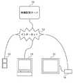
図9は、従来の映像配信サービスシステムの概念を示す図である。 FIG. 9 is a diagram showing a concept of a conventional video distribution service system.
図9において、従来の映像配信サービスシステムは、画像データを提供する映像配信サーバ10と、この映像配信サーバ10とインターネット12を介して接続され、画像データを表示又はそれに類する処理を行う携帯電話13、パーソナルコンピュータ(PC)14、並びにテレビ15及びセットトップボックス16の組み合わせ等の通信端末とから成る。この映像配信サービスシステムでは、通信端末からの送信要求に基づいて、映像配信サーバ10は、画像データを通信端末に送信し、通信端末は送信された画像データをディスプレイ等に表示する(例えば、特許文献1参照)。 In FIG. 9, a conventional video distribution service system is connected to a
近年の携帯電話、PDAの普及並びに性能・機能の向上は目覚ましく、これらの機器をインターネットに接続することも常識的なこととなっている。このような状況から、遠隔映像配信システムの通信端末として携帯電話、PDAを使用することが検討されている(例えば、特許文献2参照)
しかしながら、携帯電話やテレビ等のように通信とは別の用途を本来の目的とした端末は、映像配信サービス用の端末装置として使用される場合、本来の用途で使用している間は映像配信サービス用の端末装置としては使用することができない。例えば、携帯電話を映像配信サービス用の端末装置として使用する場合、通話中やメール作成中は映像配信サーバからライブ画像データを受信し表示することができない。 However, when a terminal originally intended for a purpose other than communication, such as a mobile phone or a TV, is used as a terminal device for a video distribution service, video distribution is performed while the terminal is used for the original purpose. It cannot be used as a service terminal device. For example, when a mobile phone is used as a terminal device for a video distribution service, live image data cannot be received and displayed from the video distribution server during a call or during mail creation.
本発明の目的は、端末装置が映像を表示できない間に表示すべき映像を後で端末装置に表示させることができる映像配信サーバ及び映像配信方法、並びにプログラム及び記憶媒体及び映像配信方法、並びにプログラム及び記憶媒体を提供することにある。 An object of the present invention is to provide a video distribution server, a video distribution method, a program, a storage medium, a video distribution method, and a program capable of causing the terminal device to display a video to be displayed later while the terminal device cannot display the video. And providing a storage medium.
上記目的を達成するために、請求項1記載の映像配信サーバは、受信した映像データを表示する表示手段を有する端末装置にネットワークを介して撮像手段から得られた映像データを送信する映像送信手段を備える映像配信サーバにおいて、前記端末装置に関する動作状況情報を受信する動作状況受信手段と、前記受信した動作状況情報に基づいて、前記映像データを前記端末装置に送信する送信モードから映像蓄積メモリに蓄積する蓄積モードに切替える切替手段とを備えることを特徴とする。 To achieve the above object, the video distribution server according to claim 1 is a video transmission means for transmitting video data obtained from an imaging means to a terminal device having a display means for displaying received video data via a network. In an image distribution server comprising: an operation status receiving means for receiving operation status information related to the terminal device; and a transmission mode for transmitting the video data to the terminal device based on the received operation status information from the transmission status to the video storage memory. And switching means for switching to the accumulation mode for accumulation.
請求項2記載の映像配信サーバは、請求項1記載の映像配信サーバにおいて、前記動作状況情報は、前記表示手段において前記映像データを表示できない処理が行われていることを示す表示不可情報を含むことを特徴とする。 The video distribution server according to
請求項3記載の映像配信サーバは、請求項1記載の映像配信サーバにおいて、前記動作状況情報は、前記映像データの表示以外の処理が行われている情報を含むことを特徴とする。 The video distribution server according to
請求項4記載の映像配信サーバは、請求項1記載の映像配信サーバにおいて、前記動作状況情報は、前記端末装置の機種とその動作状況情報との組み合わせ情報を含み、前記切替手段は、前記組み合わせ情報に基づいて前記送信モードから前記蓄積モードに切替えることを特徴とする。 The video distribution server according to
請求項5記載の映像配信サーバは、請求項1記載の映像配信サーバにおいて、前記端末装置は携帯電話から成り、前記動作状況情報は、前記携帯電話が通話中モードにあることを示すことを特徴とする。 The video distribution server according to
請求項6記載の映像配信サーバは、請求項1乃至5のいずれか1項に記載の映像配信サーバにおいて、前記映像データの蓄積が終了した後に前記送信された映像データと前記蓄積した映像データとを合成する合成手段を備え、前記映像送信手段は、前記合成された映像データを送信することを特徴とする。 The video distribution server according to
上記目的を達成するために、請求項7記載の映像配信方法は、受信した映像データを表示する表示手段を有する端末装置、及びネットワークを介して撮像手段から得られた映像データを送信する映像送信手段を備える映像配信サーバ間の映像配信方法において、前記映像サーバにおいて、前記端末装置に関する動作状況情報を受信し、前記受信した動作状況情報に基づいて、前記映像データを前記端末装置に送信する送信モードから映像蓄積メモリに蓄積する蓄積モードに切替えることを特徴とする。 In order to achieve the above object, a video distribution method according to
上記目的を達成するために、請求項8記載のプログラムは、請求項7に記載の映像配信方法をコンピュータに実行させることを特徴とする。 In order to achieve the above object, a program according to
上記目的を達成するために、請求項9記載の記憶媒体は、請求項8に記載のプログラムを記憶したことを特徴とする。 In order to achieve the above object, a storage medium according to a ninth aspect stores the program according to the eighth aspect.
請求項1記載の映像配信サーバ、請求項7記載の映像配信方法、請求項8記載のプログラム、及び請求項9記載の記憶媒体によれば、受信した端末装置に関する動作状況情報に基づいて、映像データを端末装置に送信する送信モードからメモリに蓄積する蓄積モードに切替えるので、端末装置が映像を表示できない間に表示すべき映像を後で端末装置に表示させることができる。 According to the video delivery server according to claim 1, the video delivery method according to
請求項2記載の映像配信サーバによれば、動作状況情報は、表示手段において映像データを表示できない処理が行われていることを示す表示不可情報を含むので、送信モードから蓄積モードへの替えを確実に行うことができる。 According to the video distribution server of the second aspect, since the operation status information includes display impossibility information indicating that processing for not displaying the video data is being performed on the display means, switching from the transmission mode to the accumulation mode is performed. It can be done reliably.
請求項3記載の映像配信サーバによれば、動作状況情報は、映像データの表示以外の処理が行われている情報を含むので、送信モードから蓄積モードへの切替えを確実に行うことができる。 According to the video distribution server of the third aspect, since the operation status information includes information on which processing other than display of video data is performed, switching from the transmission mode to the accumulation mode can be reliably performed.
請求項4記載の映像配信サーバによれば、動作状況情報は、端末装置の機種とその動作状況との組み合わせ情報を含み、切替手段は、組み合わせ情報に基づいて送信モードから蓄積モードに切替えるので、送信モードから蓄積モードへの切替えを容易に行うことができる。 According to the video distribution server of
請求項6記載の映像配信サーバによれば、映像データの蓄積が終了した後に前記送信された映像データと蓄積した映像データとを合成するので、端末装置における画像データの参照を一括して行うことができる。 According to the video distribution server of the sixth aspect, since the transmitted video data and the stored video data are combined after the storage of the video data is completed, the image data in the terminal device is collectively referred to. Can do.
以下、本発明の実施の形態を図面を用いて詳述する。 Hereinafter, embodiments of the present invention will be described in detail with reference to the drawings.
図1は、本発明の第1の実施の形態に係る映像配信サーバを備える映像配信サービスシステムの構成を概略的に示す図である。 FIG. 1 is a diagram schematically showing a configuration of a video distribution service system including a video distribution server according to the first embodiment of the present invention.
図1の映像配信サービスシステムは、映像配信サーバ100と、この映像配信サーバ100にビデオケーブル等で接続されたビデオカメラ110と、映像配信サーバ100とインターネット150を介して接続される携帯電話200とから成り、携帯電話200は映像配信サービス端末装置として使用される。 The video distribution service system of FIG. 1 includes a
映像配信サーバ100は、ビデオカメラ110のライブ画像データをキャプチャする映像キャプチャモジュール101と、映像キャプチャモジュール101によってキャプチャされたライブ画像データを、TCP等の一般的なネットワーク通信により携帯電話200(端末装置)に送信する映像送信モジュール102と、映像キャプチャモジュール101によってキャプチャされたライブ画像データを、携帯電話200への映像送信が一時的に停止されたときにハードディスク、メモリ等の二次記憶装置(映像蓄積装置)に蓄積する映像蓄積モジュール103と、携帯電話200から送信されてくる動作モードの動作状況情報を、映像データ通信の場合と同様にTCP等の一般的なネットワーク通信を用いて受信する動作モード受信モジュール104と、動作モード受信モジュール104によって受信した動作モードの情報に基づいて映像データを携帯電話200に送信する送信モードと映像蓄積装置に蓄積する蓄積モードのいずれかに切替えて映像データの蓄積開始終了を制御する送信蓄積切替モジュール105と、映像蓄積モジュール103が蓄積した蓄積画像データを再生して、画像としてディスプレイ上に表示する映像再生モジュール106とを備える。これらのモジュールは、ソフトウェアプログラム上の構成要素であり、不図示のROMに格納される。これらのモジュールを動作させる場合、不図示の読み書き可能であるRAMにこれらのモジュールを展開し、不図示のCPUによって動作させることができる。 The
映像キャプチャモジュール101は、画像データをデジタルデータに変換するA/D変換し、必要に応じて、JPEG等の適宜な画像フォーマットへの変換を行う。 The
映像配信サーバ100のハードウェア上の機器構成は、一般的なパーソナルコンピュータ(PC)と同等であるが、それと等価な機能をもつ他の装置であってもよい。 The hardware configuration of the
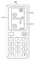
携帯電話200は、映像配信サーバ100から送信されてくるJPEGデータ形式の映像データを受信する一般的な通信方式の映像受信モジュール201と、映像受信モジュール201が受信した映像データを画像210としてディスプレイ210(図2)に表示する映像表示モジュール202と、携帯電話200の動作モードの動作状況情報を映像配信サーバ100に送信する動作モード送信モジュール203とを有する。携帯電話200は、また、通常の機能である通話のための各種手段も別途備えている。 The
携帯電話200は、携帯電話200が、いわゆる待ち受け状態にあり、何も処理を行っていない状態にある「待機中」モード、携帯電話200が通話状態にある「通話中」モード、及び携帯電話200が映像配信サーバ100と接続して映像データを取得且つ表示している状態にある「ライブ画像受付け中」モードの3つのモードを有し、これらのモードを自由に切替えることができる。 The
動作モード送信モジュール203は、上記モードが切替わるとその旨を映像配信サーバ100に送信する。 The operation
図1の映像配信サービスシステムは、ライブ画像データと同様の方式で、蓄積画像データを映像送信モジュール102から携帯電話200に送信して携帯電話200側で再生してもよく、さらに、図示しない映像合成モジュールによりライブ画像データと蓄積画像データを1枚の画像データに合成し、通話終了処理直後に、映像送信モジュール102からライブ画像データ及び蓄積画像データの合成画像を送信することにより、携帯電話200でライブ画像212と蓄積画像213を同時に参照することができるようにしてもよい(図3)。 The video distribution service system of FIG. 1 may transmit stored image data from the
図1の映像配信サービスシステムは、後述する図4のライブ画像受付け開始処理、後述する図5の通話開始処理、後述する図6の通話終了処理、後述する図7のライブ画像受付け終了処理の4つを順に実行する。 The video distribution service system in FIG. 1 includes a live image acceptance start process in FIG. 4 to be described later, a call start process in FIG. 5 to be described later, a call end process in FIG. 6 to be described later, and a live image acceptance end process in FIG. Execute them in order.
図4は、図1の映像配信サービスシステムによって実行されるライブ画像受付け開始処理のフローチャートである。 FIG. 4 is a flowchart of live image acceptance start processing executed by the video distribution service system of FIG.
本処理は、携帯電話200の、例えば専用のキーの押下等のライブ画像表示開始操作により開始する。携帯電話200には予め通知先の映像配信サーバ100が登録されており、通知に必要な情報を保持しているものとする。 This process is started by a live image display start operation of the
図4において、まず、携帯電話200が「待機中」モードにあるときに、携帯電話200において、動作モード送信モジュール203が映像配信サーバ100に「ライブ画像受付け中」モード通知を送信し(ステップS401)、映像配信サーバ100において、動作モード受信モジュール104が「ライブ画像受付け中」モード通知を受信して、この通知を送信蓄積切替モジュール105に転送する(ステップS402)。 4, first, when the
次いで、送信蓄積切替モジュール105は、映像キャプチャモジュール101が画像データ(JPEG)作成処理を実行しているか否かを判別し(ステップS403)、実行していないときは、映像キャプチャモジュール101は画像データ(JPEG)作成を開始(ステップS404)後、実行しているときは、直ちに、ステップS405に進む。 Next, the transmission /
続くステップS405では、映像配信サーバ100において、映像送信モジュール102は映像キャプチャモジュール101で作成された画像データを携帯電話200に送信し(ステップS405)、携帯電話200において、映像受信モジュール201が画像データを受信すると(ステップS406)、 映像表示モジュール202は携帯電話200のディスプレイ211に画像を表示して(ステップS407)、本処理を終了する。 In the following step S405, in the
本実施の形態では、携帯電話200は、ステップS405〜S407の処理を一定間隔(例えば1秒当たり30フレーム)で実行することにより動画表示を行う。 In the present embodiment, the
図4の処理によれば、携帯電話200が「ライブ画像受付け中」モードであるときは(ステップS401)、映像配信サーバ100から画像データを受信して(ステップS405)、携帯電話200のディスプレイに画像を表示する(ステップS407)。 According to the process of FIG. 4, when the
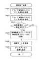
図5は、図1の映像配信サービスシステムによって実行される通話開始処理のフローチャートである。 FIG. 5 is a flowchart of a call start process executed by the video distribution service system of FIG.
本処理は、携帯電話200の発呼又は着信により開始する。 This process starts when the
図5において、まず、携帯電話200において、動作モード送信モジュール203が映像配信サーバ100に「通話中」モード通知(表示不可情報)を送信する(ステップS501)。一方、映像配信サーバ100において、動作モード受信モジュール104は携帯電話200からの「通話中」モード通知を受信して、映像配信サーバ100が配信した画像データの表示以外の処理が行われていることを認識する。そして、この通知を送信蓄積切替モジュール105に転送する(ステップS502)。 In FIG. 5, first, in the
送信蓄積切替モジュール105は、映像キャプチャモジュール101で作成した画像データの処理先を映像送信モジュール102から映像蓄積モジュール103に切替え(ステップS503)、映像蓄積モジュール103は、映像キャプチャモジュール101によって作成された画像データを不図示の二次記憶装置上に保存して(ステップS504)、本処理を終了する。 The transmission /
ステップS504における画像データの保存形式は、例えばJPEGデータを1フレームずつそのままファイルとして蓄積してもよいし、AVI形式等の他の形式に変換してもよい。ただし、このデータ形式は、何らかの形で後で再生・参照可能なものでなければならない。 As a storage format of the image data in step S504, for example, JPEG data may be stored as a file frame by frame, or may be converted into another format such as an AVI format. However, this data format must be reproducible / referenceable in some form later.
図5の処理によれば、携帯電話200が「通話中」モードにあるときは(ステップS501)、映像サーバ100において、映像キャプチャモジュール101が作成した画像データの処理先を映像蓄積モジュール103から映像送信モジュール102に切替えて(ステップS503)、映像蓄積モジュール103は画像データを二次記憶装置に蓄積する(ステップS504)。 According to the processing of FIG. 5, when the
図6は、図1の映像配信サービスシステムによって実行される通話終了処理のフローチャートである。 FIG. 6 is a flowchart of the call termination process executed by the video distribution service system of FIG.
本処理は、携帯電話200におけるユーザの通話終了操作により開始する。 This process is started by the user's call end operation on the
図6において、まず、携帯電話200が通話終了して、携帯電話200において、動作モード送信モジュール203が映像配信サーバ100に「ライブ画像受付け中」モード通知を再度送信すると(ステップS601)、映像配信サーバ100において、動作モード受信モジュール104が携帯電話200からの「ライブ画像受付け中」モード通知を受信して、この通知を送信蓄積切替モジュール105に転送する(ステップS602)。 In FIG. 6, first, when the
次いで、送信蓄積切替モジュール105は、映像蓄積モジュール103が映像データの蓄積を実行中であるか否かを判別し(ステップS603)、蓄積実行中のときは、映像キャプチャモジュール101で作成した画像データの処理先を映像蓄積モジュール103から映像送信モジュール102に切替え、これにより、映像送信モジュール102は画像データを再び携帯電話200に送信する(ステップS604)。次いで、携帯電話200において、映像受信モジュール201が画像データを受信し(ステップS605)、 映像表示モジュール202は携帯電話200のディスプレイ202に画像を表示して(ステップS606)、本処理を終了する。 Next, the transmission
ステップS603の判別の結果、映像送信モジュール102が画像データを携帯電話200に送信中であり、蓄積実行中でないときは、ステップS605以降の処理を実行して、携帯電話200において、画像データの受信及び表示を行って、本処理を終了する。 As a result of the determination in step S603, when the
図6の処理によれば、携帯電話200が通話終了して、「ライブ画像受付け中」モードになると(ステップS601)、映像サーバ100において、映像キャプチャモジュール101が作成した画像データの処理先を映像蓄積モジュール103から映像送信モジュール102に切替える(ステップS604)ので、携帯電話200が「通話中」モードにあるときに二次記憶装置に蓄積した画像データを、通話終了後に映像配信サーバ100から受信して携帯電話200のディスプレイに表示することができる。 According to the processing of FIG. 6, when the
図7は、図1の映像配信サービスシステムによって実行されるライブ画像受付け終了処理のフローチャートである。 FIG. 7 is a flowchart of live image acceptance end processing executed by the video distribution service system of FIG.
図7において、まず、携帯電話200は、動作モード送信モジュール203から映像配信サーバに「待機中」モード通知を送信し(ステップS701)、映像配信サーバ側の動作モード受信モジュール104で携帯電話からの「待機中」モード通知を受信すると(ステップS702)、この通知を送信蓄積切替モジュール105に転送する。 In FIG. 7, first, the
次いで、送信蓄積切替モジュール105は、映像送信モジュール102から携帯電話200への画像データ送信を停止させ(ステップS703)、さらに、映像キャプチャモジュール101での画像データ作成を停止させて(ステップS704)、本処理を終了する。 Next, the transmission
ただし、複数の携帯電話に同時に画像データをサービスする場合、1つの携帯電話が「待機中」モードであっても他の携帯電話が「ライブ画像受付け中」である状況では、画像データ送信は停止しても画像データ作成は停止しない。 However, when serving image data to multiple mobile phones at the same time, even if one mobile phone is in “standby” mode, the transmission of image data is stopped in situations where other mobile phones are “receiving live images”. Even then, image data creation will not stop.
上記ライブ画像受付け終了処理は、携帯電話200でのユーザのライブ画像表示終了操作により行われ、本実施の形態では、「ライブ画像受付け中」モードで行うこともできるし、「通話中」モードにおいて通話終了と同時に行うこともできる。 The live image reception end process is performed by the user's live image display end operation on the
携帯電話は200、その機種により、ある機種では、「待機中」モード、「通話中」モード、「ライブ画像受付け中」モードの3つのモード、他の機種では、「待機中」モード、「通話中」モード、「eメール参照中」モード、「ライブ画像受付中」モードの4つのモードを有する場合があり、これら複数機種の携帯電話に対しても上記実施の形態を適用することができる。 Depending on the model of the
以下、図1の映像配信サービスシステムの第1の変形例を説明する。 Hereinafter, a first modification of the video distribution service system of FIG. 1 will be described.
本第1の変形例では、送信蓄積切替モジュール105は、機種名称、動作モードの名称、蓄積要/不要フラグについての携帯電話200の機種に関するデータを有するデータベースから情報を取得することができるものである。ここで、「機種名称」は携帯電話の機種名称を表す文字列であり、「動作モード名称」は携帯電話200がサポートしている動作モードの一覧(リスト)であり、「蓄積要/不要フラグ」は、携帯電話200の各動作モードにおいて蓄積が必要か否かを表す情報である。 In the first modification, the transmission
上記携帯電話200の機種に関するデータを例示すると、機種名称としては、「携帯電話A」、動作モードとしては、「待機中」モード、「通話中」モード、及び「ライブ画像受付中」モード、蓄積要/不要フラグとしては、「待機中」モード時は「不要」、「通話中」モード時は「要」、「ライブ画像受付け中」モード時は「不要」がある。 As an example of data regarding the model of the
本第1の変形例では、携帯電話200の機種及び動作モードを文字列として扱い、当然にID番号等適当な数値として表現することもできる。 In the first modification, the model and operation mode of the
また、携帯電話200の動作モード送信モジュール203は、動作モードだけでなく機種名称も同時に送信する。 The operation
映像配信サーバ100の送信蓄積切替モジュール105は、送信されてきた携帯電話の機種名称と動作モード名称に基づいて、対応する蓄積要/不要フラグの設定値を取得する。 The transmission
蓄積要/不要フラグの設定値が「要」ならば画像データの蓄積を開始し、設定値が「不要」ならば画像データの配信を再開する。 If the setting value of the accumulation necessity / unnecessary flag is “necessary”, the accumulation of the image data is started. If the setting value is “unnecessary”, the distribution of the image data is resumed.
本第1の変形例によれば、複数機種の携帯電話に対応する実施例を実現することができる。 According to the first modification, an embodiment corresponding to a plurality of types of mobile phones can be realized.
以下、図1の映像配信サービスシステムの第2の変形例を説明する。 Hereinafter, a second modification of the video distribution service system of FIG. 1 will be described.
図1の映像配信サービスシステムでは、「待機中」モード、「通話中」モード、「ライブ画像受付け中」モードのように携帯電話200の動作モードを明確に通知してるのに対して、本第2の変形例では、携帯電話200の動作モードを明確に通知することなく、携帯電話200が画像データを表示できない処理を行っていることを映像配信サーバ100に通知するものである。 In the video distribution service system of FIG. 1, the operation mode of the
本第2の変形例では、携帯電話200は、動作モード送信モジュール203に代えて、映像配信サーバに定期的に画像データ取得要求情報(画像取得要求情報)を送信する画像要求送信モジュールを有する。一方、映像配信サーバ100は、動作モード受信モジュール104に代えて、画像データ受信要求を受信する画像要求受信モジュールを有し、携帯電話200から定期的に送信されてくる画像要求を受けると一定時間画像データを携帯電話200に送信する。 In the second modification, the
本第2の変形例では、送信蓄積切替モジュール105は、一定時間画像要求が送信されてこない場合、端末側で画像データを表示できない処理を行っているとみなしてライブ画像データ送信を停止してライブ画像データの蓄積を開始し、画像要求の送信が再開されればライブ画像データ蓄積を停止してライブ画像データの送信を再開する。 In the second modification, the transmission /
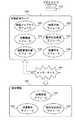
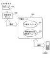
図8は、本発明の第2の実施の形態に係る映像配信サーバを備える映像配信サービスシステムの構成を概略的に示す図である。 FIG. 8 is a diagram schematically showing a configuration of a video distribution service system including a video distribution server according to the second embodiment of the present invention.
図8の映像配信サービスシステムは、映像配信サーバ100と、この映像配信サーバ100にビデオケーブル等で接続されたビデオカメラ110と、映像配信サーバ100と通信回線を介して接続された中継サーバ300と、この中継サーバ300に通信回線を介して接続された携帯電話200Aとから成る。 The video distribution service system in FIG. 8 includes a
図8において、映像配信サーバ100は図1における映像配信サーバと同じであり、携帯電話200Aは、図1における携帯電話200と同じく映像受信モジュール201及び映像表示モジュール202を有するが、図1における携帯電話200と異なり動作モード送信モジュール203を有していない。 8, the
中継サーバ300は、例えば電話の基地局や中継局に相当し、携帯電話200への通話を中継する中継モジュール301と、通話開始及び通話終了等の携帯電話200の動作モードを検知し、検知結果を映像配信サーバ100に通知する携帯電話動作モード送信モジュール302とを備える。 The
携帯電話200Aへのサービス、例えば通話は、必ず中継サーバ300を経由するものとする。 It is assumed that a service to the
中継サーバ300は、携帯電話動作モード送信モジュール302により携帯電話200Aへの通話開始・終了を検知し、検知した携帯電話200Aの動作モードを映像配信サーバ100に通知し、映像配信サーバ100は、通知を受信すると、第1の実施の形態と同様の動作を行う。 The
上記中継サーバ300は、携帯電話200がもつ動作モード送信モジュール203又は同等のものに代えて、この機能を携帯電話200や映像配信サーバ100とは別に提供することができる。 The
図8の映像配信サービスシステムによれば、映像配信サーバ100と携帯電話200を中継サーバ300を介して通信回線により接続するので、携帯電話200に特別な機能を追加することなく、必要に応じてライブ画像データの送信と蓄積を切替えることが可能となる。 According to the video distribution service system of FIG. 8, since the
上記第1及び第2の実施の形態では、端末装置は携帯電話200,200Aから成っているが、携帯電話以外の機器、例えば固定電話又はPDA、PC等であってもよい。 In the first and second embodiments, the terminal device includes the
また、本発明の目的は、上記実施形態の機能を実現するソフトウェアのプログラムコードを記録した記憶媒体(又は記録媒体)を、システム或いは装置に供給し、そのシステム又は装置のコンピュータ(又はCPUやMPU)が記憶媒体に格納されたプログラムコードを読み出し実行することによっても、達成されることは言うまでもない。 Another object of the present invention is to supply a storage medium (or recording medium) in which a program code of software for realizing the functions of the above-described embodiments is recorded to a system or apparatus, and to perform computer (or CPU or MPU) of the system or apparatus. Needless to say, this is also achieved by reading and executing the program code stored in the storage medium.
この場合、記憶媒体から読み出されたプログラムコード自体が前述した実施形態の機能を実現することになり、そのプログラムコードを記憶した記憶媒体は本発明を構成することになる。 In this case, the program code itself read from the storage medium realizes the functions of the above-described embodiments, and the storage medium storing the program code constitutes the present invention.
また、コンピュータが読み出したプログラムコードを実行することにより、前述した実施形態の機能が実現されるだけでなく、そのプログラムコードの指示に基づき、コンピュータ上で稼働しているオペレーティングシステム(OS)などが実際の処理の一部又は全部を行い、その処理によって前述した実施形態の機能が実現される場合も含まれることは言うまでもない。 Further, by executing the program code read by the computer, not only the functions of the above-described embodiments are realized, but also an operating system (OS) running on the computer based on the instruction of the program code. It goes without saying that a case where the function of the above-described embodiment is realized by performing part or all of the actual processing and the processing is included.
さらに、記憶媒体から読み出されたプログラムコードが、コンピュータに挿入された機能拡張カードやコンピュータに接続された機能拡張ユニットに備わるメモリに書き込まれた後、そのプログラムコードの指示に基づき、その機能拡張カードや機能拡張ユニットに備わるCPUなどが実際の処理の一部又は全部を行い、その処理によって前述した実施形態の機能が実現される場合も含まれることは言うまでもない。 Further, after the program code read from the storage medium is written in a memory provided in a function expansion card inserted into the computer or a function expansion unit connected to the computer, the function expansion is performed based on the instruction of the program code. It goes without saying that the CPU or the like provided in the card or the function expansion unit performs part or all of the actual processing and the functions of the above-described embodiments are realized by the processing.
また、上記プログラムは、上述した実施の形態の機能をコンピュータで実現することができればよく、その形態は、オブジェクトコード、インタプリタにより実行されるプログラム、OSに供給されるスクリプトデータ等の形態を有するものでもよい。 The above-described program only needs to be able to realize the functions of the above-described embodiments by a computer, and the form includes forms such as object code, a program executed by an interpreter, and script data supplied to the OS. But you can.
プログラムを供給する記録媒体としては、例えば、RAM、NV−RAM、フロッピー(登録商標)ディスク、光ディスク、光磁気ディスク、CD−ROM、MO、CD−R、CD−RW、DVD(DVD−ROM、DVD−RAM、DVD−RW、DVD+RW)、磁気テープ、不揮発性のメモリカード、他のROM等の上記プログラムを記憶できるものであればよい。或いは、上記プログラムは、インターネット、商用ネットワーク、若しくはローカルエリアネットワーク等に接続される不図示の他のコンピュータやデータベース等からダウンロードすることにより供給される。 As a recording medium for supplying the program, for example, RAM, NV-RAM, floppy (registered trademark) disk, optical disk, magneto-optical disk, CD-ROM, MO, CD-R, CD-RW, DVD (DVD-ROM, DVD-RAM, DVD-RW, DVD + RW), magnetic tape, non-volatile memory card, other ROM, etc. may be used as long as they can store the above programs. Alternatively, the program is supplied by downloading from another computer or database (not shown) connected to the Internet, a commercial network, a local area network, or the like.
100 映像配信サーバ
101 映像キャプチャモジュール
102 映像送信モジュール
103 映像蓄積モジュール
104 動作モード受信モジュール
105 送信蓄積切替モジュール
106 映像再生モジュール
110 ビデオカメラ
150 インターネット
200 携帯電話
201 映像受信モジュール
202 映像表示モジュール
203 動作モード送信モジュール100
Claims (9)
Translated fromJapanese前記端末装置に関する動作状況情報を受信する動作状況受信手段と、
前記受信した動作状況情報に基づいて、前記映像データを前記端末装置に送信する送信モードから映像蓄積装置に蓄積する蓄積モードに切替える切替手段とを備えることを特徴とする映像配信サーバ。In a video distribution server comprising a video transmission means for transmitting video data obtained from an imaging means via a network to a terminal device having a display means for displaying received video data,
Operational status receiving means for receiving operational status information relating to the terminal device;
A video distribution server comprising: switching means for switching from a transmission mode in which the video data is transmitted to the terminal device to a storage mode in which the video data is stored in the video storage device based on the received operation status information.
前記映像サーバにおいて、前記端末装置に関する動作状況情報を受信し、
前記受信した動作状況情報に基づいて、前記映像データを前記端末装置に送信する送信モードから映像蓄積メモリに蓄積する蓄積モードに切替えることを特徴とする映像配信方法。In a video distribution method between video distribution servers including a terminal device having a display unit for displaying received video data and a video transmission unit for transmitting video data obtained from an imaging unit via a network,
In the video server, the operation status information regarding the terminal device is received,
A video distribution method comprising: switching from a transmission mode for transmitting the video data to the terminal device to a storage mode for storing in a video storage memory based on the received operation status information.
Priority Applications (1)
| Application Number | Priority Date | Filing Date | Title |
|---|---|---|---|
| JP2004164957AJP2005348073A (en) | 2004-06-02 | 2004-06-02 | VIDEO DISTRIBUTION SERVER, VIDEO DISTRIBUTION METHOD, PROGRAM, AND STORAGE MEDIUM |
Applications Claiming Priority (1)
| Application Number | Priority Date | Filing Date | Title |
|---|---|---|---|
| JP2004164957AJP2005348073A (en) | 2004-06-02 | 2004-06-02 | VIDEO DISTRIBUTION SERVER, VIDEO DISTRIBUTION METHOD, PROGRAM, AND STORAGE MEDIUM |
Publications (1)
| Publication Number | Publication Date |
|---|---|
| JP2005348073Atrue JP2005348073A (en) | 2005-12-15 |
Family
ID=35500037
Family Applications (1)
| Application Number | Title | Priority Date | Filing Date |
|---|---|---|---|
| JP2004164957AWithdrawnJP2005348073A (en) | 2004-06-02 | 2004-06-02 | VIDEO DISTRIBUTION SERVER, VIDEO DISTRIBUTION METHOD, PROGRAM, AND STORAGE MEDIUM |
Country Status (1)
| Country | Link |
|---|---|
| JP (1) | JP2005348073A (en) |
Cited By (5)
| Publication number | Priority date | Publication date | Assignee | Title |
|---|---|---|---|---|
| JP2007228285A (en)* | 2006-02-23 | 2007-09-06 | Aiphone Co Ltd | Apartment building interphone system |
| JP2007288613A (en)* | 2006-04-18 | 2007-11-01 | Denso Corp | Push service system and information acquisition terminal |
| JP2008058404A (en)* | 2006-08-29 | 2008-03-13 | Matsushita Electric Ind Co Ltd | Music playback device and music playback terminal |
| US8588379B2 (en) | 2007-07-26 | 2013-11-19 | Nec Corporation | Multimedia communication system, multimedia communication device and terminal |
| CN112291500A (en)* | 2012-12-28 | 2021-01-29 | 格莱德通讯有限公司 | Method and apparatus for dual-mode multimedia messaging |
- 2004
- 2004-06-02JPJP2004164957Apatent/JP2005348073A/ennot_activeWithdrawn
Cited By (6)
| Publication number | Priority date | Publication date | Assignee | Title |
|---|---|---|---|---|
| JP2007228285A (en)* | 2006-02-23 | 2007-09-06 | Aiphone Co Ltd | Apartment building interphone system |
| JP2007288613A (en)* | 2006-04-18 | 2007-11-01 | Denso Corp | Push service system and information acquisition terminal |
| JP2008058404A (en)* | 2006-08-29 | 2008-03-13 | Matsushita Electric Ind Co Ltd | Music playback device and music playback terminal |
| US8588379B2 (en) | 2007-07-26 | 2013-11-19 | Nec Corporation | Multimedia communication system, multimedia communication device and terminal |
| CN112291500A (en)* | 2012-12-28 | 2021-01-29 | 格莱德通讯有限公司 | Method and apparatus for dual-mode multimedia messaging |
| CN112291500B (en)* | 2012-12-28 | 2023-04-28 | 格莱德通讯有限公司 | Method and apparatus for dual mode multimedia messaging |
Similar Documents
| Publication | Publication Date | Title |
|---|---|---|
| JP3936481B2 (en) | Content distribution apparatus and content distribution method | |
| CN100401268C (en) | Recording device and control method thereof | |
| CN101742099A (en) | camera device | |
| JP2002191079A (en) | Communication device and method, imaging device and method, data communication system, data search method, program, and storage medium | |
| JP2006013824A (en) | Storage system and method for backup data, information server used by the same, mobile terminal, and program | |
| JP2002354447A (en) | Method for distributing video | |
| JP2005348073A (en) | VIDEO DISTRIBUTION SERVER, VIDEO DISTRIBUTION METHOD, PROGRAM, AND STORAGE MEDIUM | |
| JP2001008152A (en) | Electronic camera system | |
| US7333497B2 (en) | Moving picture server and method of controlling same | |
| JP5045748B2 (en) | Information exchange method between portable terminal devices | |
| KR20030029556A (en) | Method for providing broadcast contents using a mobile terminal and computer readable record medium on which a program therefor is recorded | |
| JP2008193274A (en) | Mobile phone terminal | |
| JP4156564B2 (en) | Information processing apparatus, information processing system, information processing method, and program | |
| JP2005229241A (en) | Video processing apparatus | |
| JP2004343327A (en) | Camera with communication function, and communication system | |
| JP2006209216A (en) | Advertisement display confirmation system | |
| JP4506806B2 (en) | Broadcast communication combined terminal | |
| KR100432423B1 (en) | Transmission System and Method of Image Data to Handphone | |
| JP2008245013A (en) | Call center server | |
| JP2005229547A (en) | Recording method, recording system, reproducing method and reproducing system | |
| JPH07264572A (en) | Video information system | |
| JP2006340147A (en) | Image playback device | |
| JP2001359076A (en) | Moving picture distribution system and method, recording medium for storing moving picture distribution program | |
| JP3863498B2 (en) | VIDEO DISTRIBUTION SERVER DEVICE, VIDEO DISTRIBUTION METHOD, AND VIDEO DISTRIBUTION SYSTEM | |
| JP4902326B2 (en) | Video transmission server and control method thereof |
Legal Events
| Date | Code | Title | Description |
|---|---|---|---|
| RD03 | Notification of appointment of power of attorney | Free format text:JAPANESE INTERMEDIATE CODE: A7423 Effective date:20060418 | |
| A300 | Withdrawal of application because of no request for examination | Free format text:JAPANESE INTERMEDIATE CODE: A300 Effective date:20070807 |