JP2005347208A - Flat light source device - Google Patents
Flat light source deviceDownload PDFInfo
- Publication number
- JP2005347208A JP2005347208AJP2004168514AJP2004168514AJP2005347208AJP 2005347208 AJP2005347208 AJP 2005347208AJP 2004168514 AJP2004168514 AJP 2004168514AJP 2004168514 AJP2004168514 AJP 2004168514AJP 2005347208 AJP2005347208 AJP 2005347208A
- Authority
- JP
- Japan
- Prior art keywords
- light
- guide plate
- light source
- light guide
- degrees
- Prior art date
- Legal status (The legal status is an assumption and is not a legal conclusion. Google has not performed a legal analysis and makes no representation as to the accuracy of the status listed.)
- Pending
Links
- 230000002708enhancing effectEffects0.000abstract1
- 230000000452restraining effectEffects0.000abstract1
- 239000004973liquid crystal related substanceSubstances0.000description17
- 238000009792diffusion processMethods0.000description13
- 230000007423decreaseEffects0.000description8
- 239000000853adhesiveSubstances0.000description5
- 230000001070adhesive effectEffects0.000description5
- 230000000694effectsEffects0.000description5
- 238000004519manufacturing processMethods0.000description5
- 238000013459approachMethods0.000description4
- 238000000034methodMethods0.000description3
- 239000011347resinSubstances0.000description3
- 229920005989resinPolymers0.000description3
- 239000004925Acrylic resinSubstances0.000description2
- 229920000178Acrylic resinPolymers0.000description2
- 238000010586diagramMethods0.000description2
- 239000011521glassSubstances0.000description2
- 238000001746injection mouldingMethods0.000description2
- 239000012780transparent materialSubstances0.000description2
- RZJWLSPNMSHOHK-UHFFFAOYSA-N4-methyl-1-phenylpenta-1,4-dien-3-oneChemical compoundCC(=C)C(=O)C=CC1=CC=CC=C1RZJWLSPNMSHOHK-UHFFFAOYSA-N0.000description1
- 239000004793PolystyreneSubstances0.000description1
- 238000005520cutting processMethods0.000description1
- 150000001925cycloalkenesChemical class0.000description1
- 238000009826distributionMethods0.000description1
- 238000005530etchingMethods0.000description1
- 238000005286illuminationMethods0.000description1
- 239000000463materialSubstances0.000description1
- 238000013041optical simulationMethods0.000description1
- 239000004417polycarbonateSubstances0.000description1
- 229920000515polycarbonatePolymers0.000description1
- 229920000642polymerPolymers0.000description1
- 229920002223polystyrenePolymers0.000description1
- 238000004088simulationMethods0.000description1
- 230000002463transducing effectEffects0.000description1
Images


Landscapes
- Light Guides In General And Applications Therefor (AREA)
- Optical Elements Other Than Lenses (AREA)
- Liquid Crystal (AREA)
- Planar Illumination Modules (AREA)
Abstract
Description
Translated fromJapanese本発明は、面光源装置に係り、詳しくはLED(発光ダイオード)等の点状光源からの出射光を入射して面状に出射する面光源装置に関する。 The present invention relates to a surface light source device, and more particularly to a surface light source device that emits light emitted from a point light source such as an LED (light emitting diode) and emits the light in a planar shape.
液晶表示装置として液晶表示パネル(液晶パネル)の背面(表示面と反対側の面)に面光源装置をバックライトとして配置したものがある。この種の面光源装置として、LEDが導光板の端面と対向して配置され、導光板の表面(液晶パネルと対向する側の面)から光が面状に出射されるエッジライト方式(サイドライト型)の装置が提案されている。1個又は少ない数のLEDを使用して導光板から光を均一な面状で出射させる方法としては、導光板の採光手段としての拡散ドットと拡散シートで拡散させることによって指向性を緩和し、プリズムシートで集光して必要な輝度を得る方法がある。散乱ドットは、輝度の均一性を図るために、その密度分布を変化させて形成されている。しかし、LEDは指向性が強いため、輝線、明部、暗部などが生じやすい。 As a liquid crystal display device, there is one in which a surface light source device is disposed as a backlight on the back surface (surface opposite to the display surface) of a liquid crystal display panel (liquid crystal panel). As this type of surface light source device, an LED is disposed so as to face an end face of a light guide plate, and an edge light system (side light) in which light is emitted in a planar shape from the surface of the light guide plate (the surface facing the liquid crystal panel). Type) devices have been proposed. As a method of emitting light from the light guide plate in a uniform plane using one or a small number of LEDs, the directivity is relaxed by diffusing with diffusion dots and a diffusion sheet as the light collecting means of the light guide plate, There is a method for obtaining necessary luminance by condensing light with a prism sheet. The scattering dots are formed by changing the density distribution in order to achieve uniform brightness. However, since LEDs have strong directivity, bright lines, bright parts, dark parts, etc. are likely to occur.
また、LED等の点状光源を使用した場合に、入射面近傍で輝度ムラが発生するのを抑制するため、導光板の点状光源に対向する領域に、出射面から裏面に延びる(導光板の厚さ方向に延びる)複数の溝を設けた面光源装置が提案されている(例えば、特許文献1参照。)。特許文献1に記載の面光源装置は、図9に示すように、導光板61と、点状光源としてのLED62とを備えている。導光板61のLED62と対向する端面には、光出射面63から裏面(光出射面63と反対側の面)に延びる複数の溝64が設けられている。溝64はLED62の中心軸と直交する面に対して傾いた平面又は曲面により形成された一対の斜面64a,64bを曲面64cにより滑らかに接続して形成されている。
ところが、拡散ドットは導光板の出射面からの出射光の集光性を弱くする。また、特許文献1のように、入射面に導光板の厚さ方向に延びる複数の溝を設けることにより、入射面近傍の輝度ムラを低減させることはできる。しかし、面光源として高輝度化を図ろうとすると輝線が発生し易い。 However, the diffusion dots weaken the condensing property of the outgoing light from the outgoing surface of the light guide plate. Further, as in
本発明は前記の問題に鑑みてなされたものであって、その目的は複数の点状光源から出射された光を入射するとともに、面状に変換して出射する導光板を備えた面光源装置において、輝線の発生を抑制するとともに点状光源から導光板に入射された入射光の利用率を高めることができる面光源装置を提供することにある。 The present invention has been made in view of the above problems, and an object thereof is a surface light source device including a light guide plate that receives light emitted from a plurality of point light sources and converts the light into a planar shape and emits the light. The present invention provides a surface light source device capable of suppressing the generation of bright lines and increasing the utilization rate of incident light incident on a light guide plate from a point light source.
前記の目的を達成するため、請求項1に記載の発明は、複数の点状光源から出射された光を入射するとともに、面状に変換して出射する導光板を備えた面光源装置である。前記導光板は、入射された光を拡散させる導入部と、前記導入部に連続して形成され、前記導入部から導入された光を出射する出射面及び出射面の反対側に形成された反射部を有する板状の採光部とを備えている。前記出射面には前記採光部の導入部側の仮想端面と直交する方向に延びるとともに頂角が135度〜150度のプリズム状の突条が複数設けられている。前記導入部は、光の入射側から前記採光部側に向かって拡がる対称形状に形成されるとともにその両側面が前記仮想端面と直交する面との成す角度が15度〜45度に形成されている。また、前記導入部の前記点状光源と対向する面には、導光板の厚さ方向に延びる複数のV溝が形成され、前記V溝は頂角が60度〜90度、開放端の幅Mと隣接するV溝のピッチPとの比M/Pが0.3〜0.7に形成されている。ここで、「プリズム状の突条」とは、断面三角形のプリズムだけでなく、断面三角形のプリズムの二つの斜面の基部側が曲面に形成された形状や、断面三角形のプリズムの頂角の部分が曲面に形成された形状あるいは前記二つの斜面全体が曲面で構成されているものも含む。 In order to achieve the above object, the invention according to
この発明では、点状光源から出射され、導光板の端面から入射された光は、導光板内を前記端面と反対側の端面に向かって導波される間に採光面で反射して、出射面に向かってその進行方向が変更される。そして、出射面に設けられたプリズム状の突条を経て出射される。従って、拡散ドットを使用して点状光源から出射された光の指向性を緩和する構成に比較して、出射面からの出射光の集光性が高められる。また、点状光源からの光が、導入部によって拡散されるため、導光板全体に光を導波させることが容易になる。そして、複数の点状光源の間と対応する箇所に暗部ができたり、逆に点状光源の正面に明部ができたりすることが抑制され、導光板から出射される光の点状光源近傍に発生する輝度ムラが低減する。そして、プリズム状の突条の頂角の値及び導入部の形状を前記のように特定することにより、複数の点状光源から出射された光を入射するとともに、面状に変換して出射する導光板を備えた面光源装置において、輝線の発生を抑制するとともに点状光源から導光板に入射された入射光の利用率を高めることができる。 In this invention, the light emitted from the point light source and incident from the end face of the light guide plate is reflected by the light collecting surface while being guided toward the end face opposite to the end face within the light guide plate, and is emitted. The traveling direction is changed toward the surface. And it is radiate | emitted through the prism-shaped protrusion provided in the output surface. Therefore, the condensing property of the emitted light from the exit surface is enhanced as compared with the configuration in which the directivity of the light emitted from the point light source is relaxed using the diffusion dots. Further, since the light from the point light source is diffused by the introducing portion, it is easy to guide the light through the entire light guide plate. And it is suppressed that a dark part is made in a place corresponding to between a plurality of point light sources, and conversely a bright part is made in front of the point light source, and the vicinity of the point light source of light emitted from the light guide plate The luminance unevenness that occurs is reduced. Then, by specifying the value of the apex angle of the prism-shaped protrusion and the shape of the introduction portion as described above, the light emitted from the plurality of point light sources is incident and converted into a planar shape and emitted. In the surface light source device including the light guide plate, generation of bright lines can be suppressed and the utilization rate of incident light incident on the light guide plate from the point light source can be increased.
請求項2に記載の発明は、請求項1に記載の発明において、前記比M/Pは0.5〜0.7に形成されている。この発明では、輝線が目立たずに輝度を高めるのが容易になる。
請求項3に記載の発明は、請求項1又は請求項2に記載の発明において、前記プリズム状の突条は前記採光部と別体に形成されたプリズムシートで構成されている。この発明では、プリズム状の突条を導光板の出射面に直接形成する場合に比較して、導光板を射出成形等で製造するための金型の構造が簡単になり、導光板の製造が容易になる。The invention according to
According to a third aspect of the present invention, in the first or second aspect of the present invention, the prism-shaped protrusion is formed of a prism sheet formed separately from the daylighting unit. In this invention, the structure of the mold for manufacturing the light guide plate by injection molding or the like is simplified as compared with the case where the prismatic protrusions are directly formed on the light exit surface of the light guide plate. It becomes easy.
請求項4に記載の発明は、請求項1又は請求項2に記載の発明において、前記採光部は前記プリズム状の突条が一体に形成されている。この発明では、プリズムシートを用いる必要がないため、面光源装置を構成する部品点数が少なくなって、組立工数を低減できる。 The invention described in claim 4 is the invention described in
本発明によれば、複数の点状光源から出射された光を入射するとともに、面状に変換して出射する導光板を備えた面光源装置において、輝線の発生を抑制するとともに点状光源から導光板に入射された入射光の利用率を高めることができる。 According to the present invention, in a surface light source device that includes a light guide plate that receives light emitted from a plurality of point light sources, converts the light into a surface shape, and emits the light. The utilization factor of the incident light incident on the light guide plate can be increased.
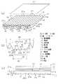
以下、本発明を液晶表示装置のサイドライト型のバックライトに使用される面光源装置に具体化した一実施形態を図1〜図7に従って説明する。図1(a)は導光板と点状光源の関係を示す模式斜視図、(b)は導入部と点状光源の関係を示す模式平面図、(c)は液晶表示装置の模式図、図2(a)は導光板の模式平面図、(b)は模式側面図、(c)は採光部の部分模式側面図である。 Hereinafter, an embodiment in which the present invention is embodied in a surface light source device used for a sidelight type backlight of a liquid crystal display device will be described with reference to FIGS. 1A is a schematic perspective view showing the relationship between the light guide plate and the point light source, FIG. 1B is a schematic plan view showing the relationship between the introducing portion and the point light source, and FIG. 1C is a schematic view of the liquid crystal display device. 2 (a) is a schematic plan view of a light guide plate, (b) is a schematic side view, and (c) is a partial schematic side view of a daylighting unit.
図1(c)に示すように、液晶表示装置11は、液晶パネル12と、その背面(表示面と反対側の面)側に配置されたバックライトとしての面光源装置13とを備えている。面光源装置13は、導光板14と、導光板14の一方の(入射側の)端部と対向する位置に配置された複数の点状光源15とを備えている。点状光源15としてはLED(発光ダイオード)が使用されている。 As shown in FIG. 1C, the liquid
面光源装置13には、導光板14を挟んで液晶パネル12と反対側に位置し、導光板14から漏れた光を導光板14に戻して出射光として利用するための反射部材(反射シート)16が設けられている。また、導光板14と液晶パネル12との間には、拡散シート17が配置されている。 The surface
次に導光板14について詳細に説明する。導光板14は透明性の高い材料、例えばアクリル樹脂で形成されている。図1(a),(b)に示すように、導光板14は、点状光源15から入射された光を拡散させる導入部18と、導入部18に連続して形成され、導入部18から導入された光を面状に出射する出射面19及び出射面19の反対側に形成された反射部20を有する板状の採光部21とを備えている。 Next, the
導入部18は複数(図1(a)では4個図示)隣接して形成されている。導入部18は、入射部22及び反射部23を備えている。導入部18は、光の入射側から導光板14の採光部21側に向かって拡がる対称形状に形成されるとともに、入射側端部の幅W1(図1(b)における左右方向の長さ)が点状光源15の幅よりも大きく形成されている。入射部22は、点状光源15と対向するとともに、導入部18の幅方向に延びる面24と平行な平面22aと、点状光源15からの光を拡散させる拡散部としてのV溝22bとが交互に等間隔で繰り返すように構成されている。V溝22bは、開放端の幅Mと、V溝22bのピッチPとの比M/Pが0.3〜0.7、好ましくは0.5〜0.7で、頂角αが60度〜90度の範囲の所定の値となるように形成されている。 A plurality of introduction portions 18 (four shown in FIG. 1A) are formed adjacent to each other. The
反射部23は、導入部18の両側面で構成され、V溝22bで拡散された光を採光部21に向けて反射するように形成されている。反射部23は平面状であり、反射部23と導入部18の幅方向に延びる面24と直交する面とのなす角度γの値が15度〜45度の範囲の所定の値となるように形成されている。 The
採光部21はほぼ四角板状に形成され、導入部18から入射された光を出射する出射面19と、出射面19の反対側の裏面に形成された反射部20とを有する。反射部20は、採光部21の導入部18側の仮想端面21a(図1(b),(c)に図示)に沿って延びるように形成された複数の平行な溝26により構成されている。なお、図1(b)においては仮想端面21aが面24と一致している。 The
溝26は、仮想端面21a側から対向面21b側に向かって上昇傾斜する採光面26aと、仮想端面21a側から対向面21b側に向かって下降傾斜する傾斜面26bとが交互に連なるように設けられている。即ち、各溝26は仮想端面21aと直交する平面による断面形状が鋸歯状となるように隣接して形成されている。各溝26は同一形状に形成されている。 The
採光面26aは、導入部18から採光部21に入射され、採光面26aに到達した光を、出射面19に形成された後記する各突条27の頂点と接する仮想平面P1(図1(a)に鎖線で図示)に対してほぼ直角に近い角度で出射面19の方向に全反射させる角度に形成されている。溝26は、採光面26aが仮想平面P1と平行な平面と成す角度θ1が例えば35度〜50度、好ましくは40度〜45度の範囲の所定の角度に、傾斜面26bが仮想平面P1と平行な平面と成す角度θ2が例えば0.3度〜2.5度の範囲の所定の角度に形成されている。 The
採光部21は、板厚tが仮想端面21a側から対向面21b側に向かって次第に小さくなるように形成されている。ここでの板厚tは、各溝26の最深部から出射面までの距離(厳密には、突条27の基端を含む面までの距離)で定義される。そして、この実施形態では板厚tは、指数関数的に減少し、次式の関数Fにおいて、n=1.5としたときに図2(b)に示す初期板厚t0等が次式を満たすように設定されている。 The
関数F:板厚(t)=t0−(t0−te)(Li/L)n…(1)
但し、t0:初期板厚、te:最終板厚、Li:仮想端面から溝までの距離、L:導光板長さである。Function F: plate thickness (t) = t0− (t0−te) (Li / L)n (1)
Where t0: initial plate thickness, te: final plate thickness, Li: distance from the virtual end face to the groove, and L: light guide plate length.
出射面19には、プリズム状の突条27が採光面26aの延びる方向と直交する方向に延びるように、即ち仮想端面21aと直交する方向に延びるように複数設けられている。各突条27は長手方向と直交する切断面での断面形状が二等辺三角形状に形成され、かつ高さが同じに形成されている。各突条27は端面が仮想平面P1とほぼ垂直になるように形成されている。また、各突条27は互いに隣接するように形成され、出射面19は仮想端面21aと直交する方向に延びる一対の斜面を有する突条27が繰り返し形成された構成となっている。突条27は、頂角Kが135度〜150度の範囲の所定の角度で、ピッチが50〜300μmの範囲の所定の大きさに形成されている。点状光源15の幅は例えば2.5mmに形成されている。なお、点状光源15、導入部18、溝26及び突条27等の大きさの比は、図示の都合上実際とは異なっている。また、図示の都合上、図1(b)及び図2では突条27の図示を省略している。 A plurality of prism-shaped
次に前記のように構成された面光源装置13の作用について説明する。
点状光源15が点灯されると、点状光源15から出射した光が導入部18から導光板14に入射し、入射した光は導光板14の出射面19から液晶パネル12に向かって出射され、拡散シート17を経て液晶パネル12に入射される。そして、液晶表示装置11の使用者は液晶パネル12の表示をその出射光により視認する。Next, the operation of the surface
When the point
導光板14における作用を詳しく説明すると、点状光源15から出射した光の大部分は入射部22に到達する。入射部22に到達した光のうち一部は、導入部18の幅方向に延びる面24と平行な平面22aから導入部18に入射される。導入部18の幅方向に延びる面24と平行な平面22aから導入部18に入射された光の多くは、平面22aにおいてその進行方向が平面22aと垂直な方向に近づくように屈折し、採光部21に入射する。 The operation of the
一方、入射部22に到達した光のうち残りの一部は、V溝22bによって、反射部23に向けて屈折されて導入部18に入射される。そして、反射部23において、その多くは採光部21の幅方向と垂直な方向に近づくように反射され、反射された光は採光部21に入射する。採光部21に入射された光は採光部21内を導波する。そのうち、採光面26aに到達した光は、図2(c)に示すように、出射面19の方向に全反射し、出射面19から出射する。 On the other hand, the remaining part of the light reaching the incident part 22 is refracted toward the
仮想端面21aから採光部21内に入射した光が全て採光面26aに向かって直進するとは限らず、採光面26aに到達する光には、傾斜面26bや出射面19で全反射しながら採光部21内を導波した後、採光面26aに到達する光もある。傾斜面26bが仮想端面21a側から対向面21b側に向かって下降傾斜するように形成されている。そのため、直接採光面26aに向かって導波する以外の光が導波を繰り返すうちに、仮想平面P1と平行な方向に近づき、結果として採光面26aで効率良く、出射面19の方向に全反射させることができる。 The light that has entered the
点状光源15から正面に向かって出射された光と、点状光源15から採光面26aに対して斜めに出射された光とを比較すると、後者の方が採光面26aで全反射して突条27内に進んだ後、突条27の表面から液晶パネル12に向かって出射される割合が大きい。これは、次の理由による。 Comparing the light emitted from the point
点状光源15から正面に出射された光は、採光面26aで仮想平面P1に略垂直に反射され、点状光源15から斜めに出射された光は、採光面26aで仮想平面P1に対して斜めに反射される。前者の光は、突条27の斜面の法線とのなす角が大きいため、突条27で反射され、内部に導波するものの割合が大きい。後者の光は、突条27の斜面の法線とのなす角が小さいため、突条27から外部に出射されるものの割合が大きい。そして、突条27から外部に出射されるとき、突条27の斜面における屈折により、後者の光の進行方向は仮想平面P1と垂直な方向に近づく。 The light emitted to the front from the point
このため、点状光源15から斜めの方向では、突条27が存在する場合には、出射面19の正面に出射する光の割合が大きくなり、突条27が存在しない場合には、出射面19の正面に出射する光の割合が小さくなる。反対に、点状光源15の正面方向では、突条27が存在する場合には、出射面19の正面に出射する光の割合が小さくなり、突条27が存在しない場合には、出射面19の正面に出射する光の割合が大きくなる。 For this reason, in the oblique direction from the point
そのため、点状光源15の指向性と関連して、突条27の頂角K、V溝22bの頂角α、反射部23の角度γの値やV溝22bの開放端の幅Mと、V溝22bのピッチPとの比M/Pが出射面19から出射される光の輝度や輝度ムラに大きく影響する。また、反射部20の形状も前記輝度や輝度ムラに影響を与える。 Therefore, in relation to the directivity of the point
本願発明者らは、光学シミュレーションにより、突条27の頂角K、V溝22bの頂角α、反射部23の角度γ、V溝22bの幅MとピッチPとの比M/Pが前記特定の組合せの場合に、面光源装置13において、輝線の発生を抑制するとともに点状光源15から導光板14に入射された入射光の利用率を高めることを見いだした。 The inventors of the present application determined by optical simulation that the ratio M / P of the apex angle K of the
シミュレーションは図2(a),(b)に示すように、4個の点状光源15を備え、出射面19と反対側の面に鋸歯状の溝26を備えた導光板14において、輝線輝度比及び中心輝度に対する、突条27の頂角K、V溝22bの頂角α、反射部23の角度γ、V溝22bの幅MとピッチPとの比M/Pを変更して行った。結果を表1〜表4及び図4〜図7に示す。 In the simulation, as shown in FIGS. 2A and 2B, the brightness of the emission line is obtained in the
なお、図2(a)〜(c)及び図1(b)に示す導光板14及び点状光源15の各部の値を次のように設定した。
導光板長さ:L=56mm、導光板幅:W=56mm、導入部の長さ:L2=5.6mm、導入部の基端幅:W2=14mm、突条のピッチ=250μm、導光板の初期板厚:t0=0.96mm、導光板の最終板厚:te=0.4mm、点状光源の幅=2.5mm、点状光源の長さ=1.0mm、鋸歯長さ:L3=0.24mm、採光面の角度:θ1=43度、傾斜面の角度:θ2=0.7度。In addition, the value of each part of the light-
Light guide plate length: L = 56 mm, light guide plate width: W = 56 mm, introduction portion length: L2 = 5.6 mm, introduction portion base end width: W2 = 14 mm, protrusion pitch = 250 μm, light guide plate length Initial plate thickness: t0 = 0.96 mm, final light guide plate thickness: te = 0.4 mm, point light source width = 2.5 mm, point light source length = 1.0 mm, sawtooth length: L3 = 0.24 mm, angle of the lighting surface: θ1 = 43 degrees, angle of the inclined surface: θ2 = 0.7 degrees.

表3は反射部23の角度γを30度に設定し、突条27の頂角K、V溝22bの頂角α、V溝22bの開放端の幅MのピッチPに対する割合を%として表したβ(=(M/P)×100)を変更した場合の輝線輝度比の値を示し、図6(a),(b),(c)はそれらをグラフに表したものである。表4は同じく中心輝度の値を示し、図7(a),(b),(c)はそれらをグラフに表したものである。 Table 3 shows that the angle γ of the reflecting
なお、輝線輝度比とは、出射面19の輝度ムラの最も大きな箇所、一般に採光部21の仮想端面21aからの距離が導光板長さLの2〜3割の位置において、導光板14の幅方向における各点の輝度を測定した際の、輝度の極大値と極小値との比を意味する。即ち、図3に示すように、導光板14の幅方向の端部からの距離を横軸xとし、輝度を縦軸にして測定値を表示すると、輝度は極大値と極小値を有するように変化するので、その極大値Aと極小値Bとの比A/Bが輝線輝度比となる。輝線輝度比の値が1に近いほど輝度ムラが小さいことを意味する。そして、輝線輝度比が1.1未満であれば実用上問題とならない。また、中心輝度は、出射面19の輝度の最大値を1としたときの中心部の輝度の相対値を表す。そして、中心輝度が0.7未満では突条27による輝度向上効果がないと見なせる。 The bright line luminance ratio is the width of the
表1,2及び図4,5から、V溝22bの頂角αを60度に設定した場合、反射部23の角度γが15度〜45度、突条27の頂角Kが135度〜150度、V溝22bの開放端の幅MのピッチPに対する割合βが30%〜70%の範囲の組み合わせで、輝線が実用上問題とならず、突条27の輝度向上効果が得られることが確認できる。また、βが50%〜70%のときには、輝度ムラがより小さくなる。 From Tables 1 and 2 and FIGS. 4 and 5, when the apex angle α of the
表3,4及び図6,7から、反射部23の角度γを30度に設定した場合、V溝22bの頂角αが60度〜90度、突条27の頂角Kが135度〜150度、V溝22bの開放端の幅MとピッチPとの割合βが30%〜70%のときに、輝線が実用上問題とならず、突条27の輝度向上効果があることが確認できる。 From Tables 3 and 4 and FIGS. 6 and 7, when the angle γ of the
また、表1〜4及び図4〜7から、突条27の頂角Kが大きくなると輝度ムラが小さくなり、突条27の頂角Kが小さくなると中心輝度が高くなることが確認できる。
この実施形態では以下の効果を有する。Further, from Tables 1 to 4 and FIGS. 4 to 7, it can be confirmed that the luminance unevenness decreases as the apex angle K of the
This embodiment has the following effects.
(1)導光板14は、入射された光を拡散させる導入部18と、導入部18に連続して形成され、導入部18から導入された光を出射する出射面19及び出射面19の反対側に形成された反射部20を有する板状の採光部21とを備えている。出射面19には採光部21の導入部18側の仮想端面21aと直交する方向に延びるとともに頂角が135度〜150度のプリズム状の突条27が複数設けられている。従って、拡散ドットを使用して点状光源15から出射された光の指向性を緩和する構成に比較して、出射面19からの出射光の集光性が高められる。 (1) The
(2)導入部18は、光の入射側から採光部21側に向かって拡がる対称形状に形成されるとともにその両側面が端面と直交する面との成す角度γが15度〜45度に形成され、導入部18の点状光源15と対向する面は頂角αが60度〜90度のV溝22bが形成されている。そして、V溝22bの開放端の幅Mと、隣接するV溝22bのピッチPとの比M/Pが0.3〜0.7、即ちM/Pの割合βが30%〜70%に形成されている。従って、点状光源15からの光が、導入部18によって適度に拡散されるため、複数の点状光源15の間と対応する箇所に暗部ができたり、逆に点状光源15の正面に明部ができたりすることが抑制され、導光板14から出射される光の点状光源15近傍に発生する輝度ムラが低減する。そして、プリズム状の突条27の頂角Kを135度〜150度とする構成を加えることで、複数の点状光源15から出射された光を入射するとともに、面状に変換して出射する導光板14を備えた面光源装置13において、輝線の発生を抑制するとともに点状光源15から導光板14に入射された入射光の利用率を高めることができる。 (2) The
(3)前記比M/Pを0.5〜0.7、即ち割合βを50%〜70%にすることにより、輝線が目立たずに輝度を高めるのが容易になる。
(4)採光部21はプリズム状の突条27が一体に形成されている。従って、プリズムシートを用いる必要がないため、面光源装置13を構成する部品点数が少なくなって、組立工数を低減でき、製造コストを低減できる。導光板14に突条27を形成する必要があるが、導光板14は金型を使用して射出成形等で製造されるため、金型のコストが多少高くなるが、多数の導光板14を製造することにより、一枚当たりの導光板14の製造コストは、突条27を設けない導光板の製造コストと、プリズムシートの単価との合計より低くできる。(3) By setting the ratio M / P to 0.5 to 0.7, that is, the ratio β to 50% to 70%, it becomes easy to increase the luminance without making the bright line noticeable.
(4) The
(5)採光部21の裏面には、仮想端面21aに沿って延びるとともに導入部18から入射された光を出射面19から出射する方向に反射させる採光面26aを構成する溝26が複数形成されている。従って、裏面にドットを設ける場合に比較して、出射面19から出射される光の向きのばらつきを小さくすることができる。 (5) On the back surface of the
(6)採光部21の裏面に形成される溝26が、反射部20の断面形状が鋸歯状で、導光板14の板厚tが、仮想端面21a側から対向面21b側に指数関数的に減少するように形成されているため、採光部21に入射した光をより効率良く、かつ出射面19全体でのばらつきを抑制した状態で出射面19から出射させることができる。また、板厚tが、前記関数Fでn=1.5としたときの各部の値を満たすように設定されている場合は、より効率良く、かつ出射面19全体でのばらつきを抑制した状態で出射面19から出射させることができる。 (6) The
(7)面光源装置13は拡散シート17を備えている。従って、導光板14において輝線が完全には防止できない場合でも、導光板14から出射された光が拡散シート17を通過して液晶パネル12に入射する際には、輝線を肉眼で判別できない状態にすることができる。 (7) The surface
実施の形態は前記に限定されるものではなく、例えば、次のように具体化してもよい。
○ 入射部22に形成される複数のV溝22bの開放端の幅M及びV溝22bのピッチPの値は同じに限らず異なる値のV溝22bが混在してもよい。その場合は、幅MのピッチPに対する割合β%を算出する際に、平均値で算出し、平均値が30%〜70%、好ましくは50%〜70%であればよい。The embodiment is not limited to the above, and may be embodied as follows, for example.
The values of the width M of the open ends of the plurality of
○ 突条27は断面が二等辺三角形状のプリズムに限らず、プリズム状であればよい。ここでプリズム状とは、断面が二等辺三角形状のプリズム及び該プリズムに近い形状を意味し、例えば、図8(a)に示すように、断面二等辺三角形状のプリズムの二つの斜面27aの基部側が曲面に形成された形状や、図8(b)に示すように、断面二等辺三角形のプリズムの頂角の部分が曲面に形成された形状としてもよい。図8(b)に示す突条27の場合、頂角Kは二つの斜面27aの平面部分が成す角度となる。これらの突条27を設けた場合も、三角プリズムで構成された突条27を設けた場合とほぼ同様な効果が得られる。 The
○ プリズム状には、図8(c),(d)に示すように、二つの斜面27a全体が曲面で構成された形状も含む。図8(c)に示すシリンドリカルな突条27では、長手方向と直交する断面において、突条27の基端の両側における2本の接線CLの成す角度が頂角Kとなり、図8(d)に示す逆シリンドリカルな突条27では、長手方向と直交する断面において、隣接する突条27の頂部における接線CLの成す角度が頂角Kとなる。これらの突条27を設けた場合も、三角プリズムで構成された突条27を設けた場合とほぼ同様な効果が得られる。 As shown in FIGS. 8C and 8D, the prism shape includes a shape in which the entire two
○ 突条27は採光部21、即ち導光板14と一体に形成されている構成に限らない。例えば、プリズム状の突条27が所定ピッチで形成されたプリズムシートを採光部21の出射面19に接着剤で接着してもよい。接着剤には、透明な紫外線硬化型接着剤や高分子系接着剤等が使用される。また、プリズムシートを採光部21の出射面19に接着剤で接着せずに、出射面19上に載置する構成としてもよい。 The
○ 採光部21は、板厚tがマクロ的に見て仮想端面21a側から対向面21b側に向かって次第に薄くなるほぼ楔状に限らず、マクロ的に見て一定な形状としてもよい。
○ 採光部21の出射面19と反対側に設けられる反射部20は、採光面26aと傾斜面26bとが交互に連続する鋸歯状の溝26を備えた構成に限らず、導入部18から入射されて板厚方向と直交する方向に進む光を出射面19に向けて全反射させる斜面を備えた構成であればよい。例えば、仮想端面21aと平行に延びるV溝や断面直角三角形状の溝が複数平行に形成された構成や、出射面19と反対側の面に円錐状あるいは角錐状の凹部を設けることで形成された複数のマイクロレンズを備えた構成としてもよい。The
The reflecting
〇 面光源装置13において拡散シート17を省略してもよい。拡散シート17を設ける方が、面光源装置13の出射面全体の輝度ムラを低くすることができる。しかし、面光源装置13が使用される表示装置に要求される表示部の精細度によっては、拡散シート17を省略しても、輝度ムラが気にならない状態に抑制できる。 The
○ 導光板14に使用される材料としては、透明で成形型を使用して加工をすることができるものが好ましく、例えば、アクリル樹脂に限らず、ポリカーボネート、ポリスチレン、MS樹脂(メタクリルスチレン樹脂)、シクロオレフィン樹脂等が使用される。 ○ The material used for the
○ 導光板14をガラス板で形成してもよい。しかし、ガラス板に突条27や溝26等をエッチングで加工するのはコストが高くなる。
○ 面光源装置13はバックライト用に限らず、他の照明装置やディスプレイ装置の発光源として使用してもよい。○ The
The surface
以下の技術的思想(発明)は前記実施の形態から把握できる。
(1)請求項1〜請求項4のいずれか一項に記載の発明において、前記採光部は反射部として、採光部の入射側仮想端面と平行に延びるとともに前記入射された光を前記出射面から出射する方向に反射させる採光面を構成する溝が複数形成されている。The following technical idea (invention) can be understood from the embodiment.
(1) In the invention according to any one of
(2)前記技術的思想(1)に記載の発明において、前記採光部における導光板の各溝の最深部から前記出射面まで距離としての板厚tが、前記仮想端面側から対向面側へと指数関数的に単調減少するように設定されている。 (2) In the invention described in the technical idea (1), a plate thickness t as a distance from the deepest part of each groove of the light guide plate in the daylighting unit to the emission surface is from the virtual end surface side to the opposing surface side. And is set to decrease monotonically exponentially.
(3)入射された光を拡散させる導入部と、前記導入部に連続して形成され、前記導入部から導入された光を出射する出射面及び出射面の反対側に形成された反射部を有する板状の採光部とを備え、前記出射面には前記採光部の導入部側の仮想端面と直交する方向に延びるとともに頂角が135度〜150度のプリズム状の突条が複数設けられ、前記導入部は、光の入射側から前記採光部側に向かって拡がる対称形状に形成されるとともにその両側面が前記仮想端面と直交する面との成す角度が15度〜45度に形成され、前記導入部の前記点状光源と対向する面には導光板の厚さ方向に延びる複数のV溝が形成され、前記V溝は頂角が60度〜90度、開放端の幅Mと隣接するV溝のピッチPとの比M/Pが0.3〜0.7に形成されている導光板。 (3) An introduction part that diffuses incident light, an emission surface that is formed continuously from the introduction part, emits light introduced from the introduction part, and a reflection part that is formed on the opposite side of the emission surface. A plurality of prismatic protrusions extending in a direction perpendicular to the virtual end surface on the introduction portion side of the daylighting section and having an apex angle of 135 degrees to 150 degrees. The introduction part is formed in a symmetric shape that spreads from the light incident side toward the daylighting part side, and an angle formed between a side surface of the introduction part and a surface orthogonal to the virtual end face is 15 degrees to 45 degrees. A plurality of V-grooves extending in the thickness direction of the light guide plate are formed on a surface of the introducing portion facing the point light source, and the V-groove has an apex angle of 60 to 90 degrees and an open end width M. The ratio M / P with the pitch P of the adjacent V groove is 0.3 to 0.7. The light guide plate.
α,K…頂角、γ,θ1,θ2…角度、M…幅、P…ピッチ、13…面光源装置、14…導光板、15…点状光源、18…導入部、19…出射面、20…反射部、21…採光部、21a…仮想端面、22b…V溝、23…側面としての反射部、24…面、27…突条。 α, K ... vertex angle, γ, θ1, θ2 ... angle, M ... width, P ... pitch, 13 ... surface light source device, 14 ... light guide plate, 15 ... point light source, 18 ... introduction part, 19 ... exit surface, DESCRIPTION OF
Claims (4)
Translated fromJapanese前記導光板は、入射された光を拡散させる導入部と、前記導入部に連続して形成され、前記導入部から導入された光を出射する出射面及び出射面の反対側に形成された反射部を有する板状の採光部とを備え、前記出射面には前記採光部の導入部側の仮想端面と直交する方向に延びるとともに頂角が135度〜150度のプリズム状の突条が複数設けられ、前記導入部は、光の入射側から前記採光部側に向かって拡がる対称形状に形成されるとともにその両側面が前記仮想端面と直交する面との成す角度が15度〜45度に形成され、前記導入部の前記点状光源と対向する面には導光板の厚さ方向に延びる複数のV溝が形成され、前記V溝は頂角が60度〜90度、開放端の幅Mと隣接するV溝のピッチPとの比M/Pが0.3〜0.7に形成されている面光源装置。A surface light source device that includes a light guide plate that receives light emitted from a plurality of point light sources, converts the light into a planar shape, and emits the light.
The light guide plate is formed continuously with the introduction part for diffusing incident light, the emission surface for emitting the light introduced from the introduction part, and a reflection formed on the opposite side of the emission surface. A plurality of prismatic ridges extending in a direction perpendicular to the virtual end surface on the introduction portion side of the daylighting section and having an apex angle of 135 degrees to 150 degrees. The introduction part is formed in a symmetric shape that spreads from the light incident side toward the daylighting part side, and the angle formed between the side surfaces of the introduction part and the surface perpendicular to the virtual end face is 15 degrees to 45 degrees. A plurality of V-grooves extending in the thickness direction of the light guide plate are formed on a surface of the introducing portion facing the point light source, and the V-groove has an apex angle of 60 degrees to 90 degrees and an open end width. The ratio M / P between M and the pitch P of the adjacent V groove is 0.3 to 0.7. It is to have the surface light source device.
Priority Applications (1)
| Application Number | Priority Date | Filing Date | Title |
|---|---|---|---|
| JP2004168514AJP2005347208A (en) | 2004-06-07 | 2004-06-07 | Flat light source device |
Applications Claiming Priority (1)
| Application Number | Priority Date | Filing Date | Title |
|---|---|---|---|
| JP2004168514AJP2005347208A (en) | 2004-06-07 | 2004-06-07 | Flat light source device |
Publications (1)
| Publication Number | Publication Date |
|---|---|
| JP2005347208Atrue JP2005347208A (en) | 2005-12-15 |
Family
ID=35499380
Family Applications (1)
| Application Number | Title | Priority Date | Filing Date |
|---|---|---|---|
| JP2004168514APendingJP2005347208A (en) | 2004-06-07 | 2004-06-07 | Flat light source device |
Country Status (1)
| Country | Link |
|---|---|
| JP (1) | JP2005347208A (en) |
Cited By (16)
| Publication number | Priority date | Publication date | Assignee | Title |
|---|---|---|---|---|
| JP2007194214A (en)* | 2006-01-16 | 2007-08-02 | Samsung Electro Mech Co Ltd | Light guide plate and display device using the same |
| KR100801255B1 (en)* | 2006-11-21 | 2008-02-04 | 주식회사 나모텍 | Backlight Unit of LCD |
| JP2009129792A (en)* | 2007-11-27 | 2009-06-11 | Minebea Co Ltd | Surface lighting device |
| US7637646B2 (en) | 2006-06-30 | 2009-12-29 | Lg Display Co., Ltd. | Backlight assembly and liquid crystal display device having the same |
| CN100582823C (en)* | 2006-12-25 | 2010-01-20 | 鸿富锦精密工业(深圳)有限公司 | light conducting plate and backlight module group |
| CN100590492C (en)* | 2006-01-20 | 2010-02-17 | 友达光电股份有限公司 | Light guide plate structure, backlight module comprising same and liquid crystal display |
| JP2010517214A (en)* | 2007-01-19 | 2010-05-20 | コーニンクレッカ フィリップス エレクトロニクス エヌ ヴィ | Lighting device |
| JP2010282908A (en)* | 2009-06-08 | 2010-12-16 | Hayashi Telempu Co Ltd | Lighting device |
| JP2011048930A (en)* | 2009-08-25 | 2011-03-10 | Toppan Printing Co Ltd | Light guide plate, backlight unit, and display device |
| WO2011039896A1 (en)* | 2009-09-30 | 2011-04-07 | シャープ株式会社 | Light source module and electronic apparatus with same |
| JP2011113866A (en)* | 2009-11-27 | 2011-06-09 | Dainippon Printing Co Ltd | Light guide plate, surface light source device, and display device |
| JP2012003883A (en)* | 2010-06-15 | 2012-01-05 | Dainippon Printing Co Ltd | Light guide plate, planar light source device, and display device |
| JP2012230836A (en)* | 2011-04-26 | 2012-11-22 | Asahi Kasei Corp | Light guide plate, surface light source device and display device |
| US8797480B2 (en) | 2011-10-18 | 2014-08-05 | Dai Nippon Printing Co., Ltd. | Light guide plate, surface light source device, and display device |
| KR101509370B1 (en)* | 2011-02-15 | 2015-04-07 | 미쓰비시덴키 가부시키가이샤 | Surface light source device and liquid crystal display device |
| JP7671135B2 (en) | 2016-10-04 | 2025-05-01 | マクセル株式会社 | Light source device and head-up display device |
- 2004
- 2004-06-07JPJP2004168514Apatent/JP2005347208A/enactivePending
Cited By (21)
| Publication number | Priority date | Publication date | Assignee | Title |
|---|---|---|---|---|
| JP2007194214A (en)* | 2006-01-16 | 2007-08-02 | Samsung Electro Mech Co Ltd | Light guide plate and display device using the same |
| CN100590492C (en)* | 2006-01-20 | 2010-02-17 | 友达光电股份有限公司 | Light guide plate structure, backlight module comprising same and liquid crystal display |
| US7637646B2 (en) | 2006-06-30 | 2009-12-29 | Lg Display Co., Ltd. | Backlight assembly and liquid crystal display device having the same |
| KR100989219B1 (en)* | 2006-06-30 | 2010-10-20 | 엘지디스플레이 주식회사 | A backlight assembly and a liquid crystal display having the same. |
| KR100801255B1 (en)* | 2006-11-21 | 2008-02-04 | 주식회사 나모텍 | Backlight Unit of LCD |
| CN100582823C (en)* | 2006-12-25 | 2010-01-20 | 鸿富锦精密工业(深圳)有限公司 | light conducting plate and backlight module group |
| JP2010517214A (en)* | 2007-01-19 | 2010-05-20 | コーニンクレッカ フィリップス エレクトロニクス エヌ ヴィ | Lighting device |
| JP2009129792A (en)* | 2007-11-27 | 2009-06-11 | Minebea Co Ltd | Surface lighting device |
| JP2010282908A (en)* | 2009-06-08 | 2010-12-16 | Hayashi Telempu Co Ltd | Lighting device |
| JP2011048930A (en)* | 2009-08-25 | 2011-03-10 | Toppan Printing Co Ltd | Light guide plate, backlight unit, and display device |
| WO2011039896A1 (en)* | 2009-09-30 | 2011-04-07 | シャープ株式会社 | Light source module and electronic apparatus with same |
| CN102089573A (en)* | 2009-09-30 | 2011-06-08 | 夏普株式会社 | Light source module and electronic apparatus with same |
| JP5203462B2 (en)* | 2009-09-30 | 2013-06-05 | シャープ株式会社 | Light source module and electronic device including the same |
| JP2011113866A (en)* | 2009-11-27 | 2011-06-09 | Dainippon Printing Co Ltd | Light guide plate, surface light source device, and display device |
| JP2012003883A (en)* | 2010-06-15 | 2012-01-05 | Dainippon Printing Co Ltd | Light guide plate, planar light source device, and display device |
| KR101509370B1 (en)* | 2011-02-15 | 2015-04-07 | 미쓰비시덴키 가부시키가이샤 | Surface light source device and liquid crystal display device |
| US9103950B2 (en) | 2011-02-15 | 2015-08-11 | Mitsubishi Electric Corporation | Surface light source device and liquid crystal display device |
| JP2012230836A (en)* | 2011-04-26 | 2012-11-22 | Asahi Kasei Corp | Light guide plate, surface light source device and display device |
| US8797480B2 (en) | 2011-10-18 | 2014-08-05 | Dai Nippon Printing Co., Ltd. | Light guide plate, surface light source device, and display device |
| US9217821B2 (en) | 2011-10-18 | 2015-12-22 | Dai Nippon Printing Co., Ltd. | Light guide plate, surface light source device, and display device |
| JP7671135B2 (en) | 2016-10-04 | 2025-05-01 | マクセル株式会社 | Light source device and head-up display device |
Similar Documents
| Publication | Publication Date | Title |
|---|---|---|
| JP4436105B2 (en) | Reflector, illumination device, light guide plate, and display device | |
| TWI270703B (en) | Lightguide plate, area light source apparatus, and liquid crystal display | |
| JP6285783B2 (en) | Light capture structure for light emitting applications | |
| US8210731B2 (en) | Light guide plate, and planar lighting device and liquid crystal display device using the same | |
| JP2005347208A (en) | Flat light source device | |
| TW200420856A (en) | Optical waveguide, area light source device and liquid crystal display device | |
| CN102906489A (en) | Light guide plate, surface light source device and display device | |
| TW201124760A (en) | Light guide plate, light guide plate manufacturing method, surface light source device, and liquid crystal display device | |
| KR101257831B1 (en) | Optical Strip and Backlight Module and LCD Device Having the Optical Strip | |
| US10012783B2 (en) | Lighting system using a light guide and a lighting method | |
| JP4119469B2 (en) | Optical member and backlight unit using the same | |
| JPH11231320A (en) | Side light type planar light source unit and liquid crystal display device | |
| US20070274103A1 (en) | Light guide panel and a backlight unit using the same | |
| JP2009135116A (en) | Surface light source device, prism sheet, display device and information processing device | |
| JP2005085671A (en) | Light guide plate and plane light source device | |
| JP2005353406A (en) | Light guide plate | |
| JP2005063913A (en) | Light guide plate | |
| WO2013002015A1 (en) | Illuminating device and display device | |
| JP2005108512A (en) | Light guide plate and surface light source device | |
| JP2005063912A (en) | Light guide plate and its manufacturing method | |
| TW201426125A (en) | Light guide plate and backlight module | |
| JP2004192937A (en) | Light guide plate | |
| KR100639549B1 (en) | Light guide plate, surface light source apparatus, and liquid crystal display | |
| JP2006202639A (en) | Backlight device | |
| JP2006202639A5 (en) |