JP2005341993A - Overtube for endoscope - Google Patents
Overtube for endoscopeDownload PDFInfo
- Publication number
- JP2005341993A JP2005341993AJP2004161620AJP2004161620AJP2005341993AJP 2005341993 AJP2005341993 AJP 2005341993AJP 2004161620 AJP2004161620 AJP 2004161620AJP 2004161620 AJP2004161620 AJP 2004161620AJP 2005341993 AJP2005341993 AJP 2005341993A
- Authority
- JP
- Japan
- Prior art keywords
- overtube
- endoscope
- balloon
- main body
- hard
- Prior art date
- Legal status (The legal status is an assumption and is not a legal conclusion. Google has not performed a legal analysis and makes no representation as to the accuracy of the status listed.)
- Pending
Links
Images


Landscapes
- Endoscopes (AREA)
Abstract
Description
Translated fromJapaneseこの発明は、経口的または経肛門的に体腔内に挿入して体腔内を観察する内視鏡の挿入部に外挿される内視鏡用オーバーチューブに関する。 The present invention relates to an endoscope overtube that is inserted into an insertion portion of an endoscope that is orally or transanally inserted into a body cavity and observes the inside of the body cavity.
例えば、小腸内視鏡を体腔内の小腸へ挿入する場合の手技として、経口的に挿入する場合と経肛門的に挿入する場合とがある。いずれにしても、腸管は複雑に屈曲をしているために、体腔外で内視鏡の挿入部を押し進めても、挿入部の先端部に力が伝わり難く、深部へ挿入することは困難である。 For example, as a procedure for inserting a small intestine endoscope into a small intestine in a body cavity, there are a case where it is inserted orally and a case where it is inserted transanally. In any case, since the intestinal tract is bent flexibly, even if the insertion part of the endoscope is pushed out of the body cavity, it is difficult to transmit the force to the distal end of the insertion part, and it is difficult to insert it deeply. is there.
そこで、内視鏡の挿入部を複雑に屈曲した腸管にスムーズに挿入できるように、内視鏡の先端部に内視鏡用バルーンを設けると共に、内視鏡挿入部に外挿したオーバーチューブ(スライディグチューブ)の先端部にオーバーチューブ用バルーンを設けたダブルバルーン式内視鏡システムが知られている(例えば、特許文献1参照。)。 Therefore, an endoscope tube is provided at the distal end portion of the endoscope so that the insertion portion of the endoscope can be smoothly inserted into a complicatedly bent intestine, and an overtube (externally inserted into the endoscope insertion portion) Sly dig tube) double-balloon endoscope system in which a balloon overtube distal end has been known (e.g., see Patent Document 1.).
これは、内視鏡挿入部を深部に挿入する際のガイドとしての役目を果たすオーバーチューブを腸管の深部まで挿入した後、オーバーチューブ用バルーンを膨らましてオーバーチューブ用バルーンを腸管に固定し、この状態で、オーバーチューブを後退させることにより、腸管の撓みをとって内視鏡挿入部をより深部に挿入するようになっている。 This is because after inserting the overtube that serves as a guide when inserting the endoscope insertion portion into the deep part to the deep part of the intestinal tract, the overtube balloon is inflated to fix the overtube balloon to the intestinal tract. state, by retracting the overtube is adapted to insert the endoscope insertion portion into a deeper portion taking the deflection of the intestinal tract.
また、オーバーチューブ用バルーンを膨らましてオーバーチューブを腸管に固定する際に、腸管等に負担を掛けないように、バルーンの材質をラテックスのように軟質のものにしたもの、またバルーンの内圧を測定して圧力を制御できるようにしたものも知られている(例えば、特許文献2,3参照。)。
特許文献1〜3は、いずれも内視鏡の挿入部の先端部に内視鏡用バルーンが固定され、ポンプ装置によって内視鏡用バルーンに送気したり、吸引することにより、膨張・収縮することができる。また、内視鏡挿入部に外挿したオーバーチューブの先端部にオーバーチューブ用バルーンを設けたダブルバルーン式内視鏡も、オーバーチューブ用バルーンに送気したり、吸引することにより、膨張・収縮することができる。 In each of Patent Documents 1 to 3, an endoscope balloon is fixed to the distal end portion of the insertion portion of the endoscope, and the pump device is inflated and contracted by supplying air to or sucking the endoscope balloon. can do. In addition, double-balloon endoscopes with an overtube balloon provided at the distal end of the overtube extrapolated to the endoscope insertion section can also be inflated and contracted by supplying air to the overtube balloon or sucking it. can do.
しかし、内視鏡の挿入部に外挿されるオーバーチューブは、薄肉の合成樹脂チューブ等によって形成され、可撓性に富んでいる。従って、オーバーチューブ全体の腰が弱く、オーバーチューブの手元側を持って先端側に押し込んだとき、オーバーチューブの途中で座屈してオーバーチューブの先端側に力が伝達されない。つまり、オーバーチューブの手元側を持って先端側に押し進めようとしてもオーバーチューブの先端部は前進し難いという問題がある。 However, the overtube that is externally inserted into the insertion portion of the endoscope is formed of a thin synthetic resin tube or the like, and is highly flexible. Accordingly, the waist of the entire overtube is weak, and when it is pushed into the distal end side while holding the proximal side of the overtube, it buckles in the middle of the overtube and no force is transmitted to the distal end side of the overtube. That is, there is a problem that even if the hand side of the overtube is held and pushed forward, the tip of the overtube is difficult to advance.
そこで、オーバーチューブの腰を強くするために、硬質にすると、可撓性が失われて挿入性が悪くなる。また、オーバーチューブの肉厚を厚くすることも考えられるが、肉厚を厚くすると、オーバーチューブの外径が太くなり、管腔への挿入性が悪くなり、術者及び患者の負担が大きくなる。 Therefore, if the overtube is made hard in order to strengthen the waist, the flexibility is lost and the insertability is deteriorated. Also, it is conceivable to increase the thickness of the overtube. However, if the thickness is increased, the outer diameter of the overtube becomes thicker, the insertion into the lumen is worsened, and the burden on the operator and the patient is increased. .
この発明は、前記事情に着目してなされたもので、その目的とするところは、オーバーチューブの外径を最小限に抑えると共に、オーバーチューブの腰が強くなり、管腔への挿入性を向上できる内視鏡用オーバーチューブを提供することにある。 The present invention has been made by paying attention to the above circumstances, and the object thereof is to minimize the outer diameter of the overtube and to increase the waist of the overtube, thereby improving the insertion into the lumen. An object of the present invention is to provide an overtube for an endoscope.
この発明は、前記目的を達成するために、請求項1は、内視鏡の挿入部に外挿される内視鏡用オーバーチューブにおいて、可撓性を有するオーバーチューブ本体の周方向の一部に少なくとも周辺よりも硬質な部位を軸方向の全長に渡って設けたことを特徴とする。 In order to achieve the above object, according to a first aspect of the present invention, there is provided an endoscope overtube that is externally inserted into an insertion portion of an endoscope. At least a portion harder than the periphery is provided over the entire length in the axial direction.
請求項2は、請求項1の前記硬質な部位は、前記オーバーチューブ本体に形成した偏肉部であることを特徴とする。 A second aspect of the present invention is characterized in that the hard portion according to the first aspect is an uneven thickness portion formed in the overtube body.
請求項3は、請求項1の前記硬質な部位は、前記オーバーチューブ本体の軸方向の全長に渡って埋設した硬質のワイヤで形成したことを特徴とする。 A third aspect of the present invention is characterized in that the hard portion of the first aspect is formed of a hard wire embedded over the entire axial length of the overtube body.
請求項4は、請求項1,2または3の前記オーバーチューブ本体の材質は、少なくとも内面にフッ素系樹脂を用いたことを特徴とする。 A fourth aspect of the present invention is characterized in that the material of the overtube main body of the first, second or third aspect uses a fluorine-based resin at least on the inner surface.
請求項5は、内視鏡の挿入部に外挿される内視鏡用オーバーチューブにおいて、オーバーチューブ本体は中空部を有する円筒体で形成すると共に、円筒体内に送気する空気圧によって前記オーバーチューブ本体の硬度を調整できることを特徴とする。 5. The endoscope overtube externally inserted into the insertion portion of the endoscope, wherein the overtube main body is formed of a cylindrical body having a hollow portion, and the overtube main body is supplied by air pressure fed into the cylindrical body. The hardness can be adjusted.
請求項6は、請求項5の前記中空部は、前記オーバーチューブ本体の周方向の少なくとも一部で、かつ全長に渡って設けたことを特徴とする。 A sixth aspect of the present invention is characterized in that the hollow portion of the fifth aspect is provided over at least a part of the circumferential direction of the overtube main body and over the entire length.
請求項7は、内視鏡の挿入部に外挿される内視鏡用オーバーチューブにおいて、オーバーチューブ本体に挿入方向に沿って管路を設けると共に、前記管路に硬質のワイヤを挿入することによって前記オーバーチューブ本体の硬度を調整できることを特徴とする。 According to a seventh aspect of the present invention, in the endoscope overtube extrapolated to the insertion portion of the endoscope, a pipe line is provided in the overtube body along the insertion direction, and a hard wire is inserted into the pipe line. The overtube body can be adjusted in hardness.
請求項8は、請求項7の前記ワイヤは、硬度の異なる複数の種類からなることを特徴とする。 An eighth aspect of the present invention is characterized in that the wire according to the seventh aspect comprises a plurality of types having different hardnesses.
この発明によれば、オーバーチューブ本体の周方向の一部に少なくとも周辺よりも硬質な部位を軸方向の全長に渡って設けることにより、オーバーチューブの外径を最小限に抑えると共に、オーバーチューブの腰が強くなり、管腔への挿入性を向上できる。従って、術者及び患者の負担を軽減できるという効果がある。 According to the present invention, by providing at least a portion harder than the periphery in the circumferential direction of the overtube body over the entire length in the axial direction, the outer diameter of the overtube is minimized, and the overtube The waist becomes strong and the insertion into the lumen can be improved. Therefore, there is an effect that the burden on the operator and the patient can be reduced.
以下、この発明の各実施の形態を図面に基づいて説明する。 Embodiments of the present invention will be described below with reference to the drawings.
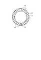
図1〜図3は第1の実施形態であり、図1は医療システムの全体構成図、図2はダブルバルーン式内視鏡の先端部の縦断側面図、図3はオーバーチューブの横断面図である。 1 to 3 show a first embodiment, FIG. 1 is an overall configuration diagram of a medical system, FIG. 2 is a longitudinal side view of a distal end portion of a double balloon endoscope, and FIG. 3 is a cross-sectional view of an overtube. It is.
図1及び図2は、小腸用の内視鏡1を示し、この内視鏡1は細長い軟性の挿入部2を有しており、挿入部2の遠位端(先端側)には湾曲部3を介して先端構成部4が設けられている。挿入部2の近位端(基端側)にはグリップ部を有する操作部5が設けられており、この操作部5には遠位端にコネクタ6を有するユニバーサルコード7が接続されている。 1 and 2 show an endoscope 1 for the small intestine. The endoscope 1 has an elongated
挿入部2には処置用チャンネル、先端構成部4には照明光学系、固体撮像素子等の観察光学系、処置用チャンネルと連通する鉗子口、体腔内に空気および観察レンズに水を供給するノズル(いずれも図示しない)が設けられ、処置用チャンネルは、操作部5の処置具挿入口8と連通している。操作部5には湾曲部3を湾曲操作するアングル操作ノブ9が設けられ、アングルワイヤ(図示しない)を押し引きすることにより、湾曲部3を湾曲できるようになっている。 The
前記挿入部2には、該挿入部2に外挿される内視鏡用オーバーチューブ10が挿入軸方向に進退自在に設けられている。内視鏡用オーバーチューブ10のオーバーチューブ本体11は、図3に示すように、可撓性を有する合成樹脂チューブ、例えば、フッ素系樹脂等によって円筒状に形成され、その周方向の一部には周辺よりも硬質な部位として、偏肉部、つまり肉厚部11aが形成され、その肉厚部11aはオーバーチューブ本体11の軸方向の全長に渡って設けられている。すなわち、オーバーチューブ本体11は可撓性を有する合成樹脂チューブ、例えばフッ素系樹脂等によって円筒状に形成されているが、オーバーチューブ本体11の外径を太くすることなく、周方向の一部を周辺の肉薄部11bよりも漸次肉厚に形成され、その肉厚部11aによってオーバーチューブ本体11が座屈し難く、腰が強く形成されている。 The
さらに、オーバーチューブ本体11は、外径及び内径が真円に形成され、しかもフッ素系樹脂は自己潤滑性に優れていることから、内周部は内視鏡1の挿入部2との摩擦を低減でき、外周部は体腔内の管腔との摩擦を低減できる。 Furthermore, since the
また、前記内視鏡2の先端構成部4には膨張・収縮自在な内視鏡用バルーン12が装着され、内視鏡用オーバーチューブ10の遠位端(先端側)には膨張・収縮自在なオーバーチューブ用バルーン13が装着されている。 An
さらに、内視鏡1の挿入部2の内部には、その挿入軸方向に渡って第1の送気管路15が内挿され、この第1の送気管路15の遠位端は先端構成部4の径方向に貫通する開口部16を介して内視鏡用バルーン12の内腔に連通している。また、第1の送気管路15の近位端は操作部5を介してユニバーサルコード7のコネクタ6まで延長している。 Furthermore, a first
内視鏡用オーバーチューブ10のオーバーチューブ用バルーン13は両端部が縛り糸17a,17bによって内視鏡用オーバーチューブ10に固定されている。内視鏡用オーバーチューブ10の外周面の一部にはオーバーチューブ用バルーン13へ送気する第2の送気管路19が添設されている。この第2の送気管路19は内視鏡用オーバーチューブ10の近位端に設けられた把持部20まで延長している。 Both ends of the
ユニバーサルコード7のコネクタ6には第1の送気管路15と連通する送気接続口21が設けられている。この送気接続口21は第1の接続チューブ22を介してバルーン制御装置23に接続されている。また、内視鏡用オーバーチューブ10の把持部20には第2の送気管路19と連通する送気接続口24が設けられている。この送気接続口24は第2の接続チューブ25を介してバルーン制御装置23に接続されている。バルーン制御装置23にはフットスイッチ26が接続され、バルーン制御装置23を制御して内視鏡用バルーン12及びオーバーチューブ用バルーン13を膨張・収縮操作できるようになっている。 The connector 6 of the universal cord 7 is provided with an air
また、ユニバーサルコード7のコネクタ6は、ビデオプロセッサ27を介して観察モニター28に接続されている。観察モニター28には内視鏡1の観察画像、被検者の個人情報、内視鏡用バルーン12とオーバーチューブ用バルーン13の膨張・収縮状態、バルーン圧力値等が文字表示され、術者は内視鏡1の観察画像とともに内視鏡用バルーン12とオーバーチューブ用バルーン13の膨張・収縮状態、バルーン圧力値等が把握できるようになっている。 The connector 6 of the universal cord 7 is connected to the observation monitor 28 via the
次に、前述のように構成された医療システムの作用について説明する。 Next, the operation of the medical system configured as described above will be described.
ダブルバルーン式内視鏡1を経口的に小腸に挿入して腸管の内壁を観察する場合、まず、内視鏡1の挿入部2にオーバーチューブ10を外挿し、フットスイッチ26の操作によってバルーン制御装置23を制御し、内視鏡用バルーン12及びオーバーチューブ用バルーン13のエアを抜いて収縮状態とする。 When the double balloon endoscope 1 is orally inserted into the small intestine and the inner wall of the intestine is observed, the
次に、内視鏡1の挿入部2を患者aの口bから挿入し、操作部5のアングル操作ノブ9を操作して湾曲部3を湾曲操作しながら、挿入部2を食道、胃を経て小腸に挿入する。そして、内視鏡1の挿入部2の先端構成部4が例えば十二指腸を通過したところで、フットスイッチ26を操作してバルーン制御装置23を制御する。 Next, the
そして、バルーン制御装置23から第1の接続チューブ22、第1の送気管路15を介して開口部16から内視鏡用バルーン12にエアを供給して内視鏡用バルーン13を膨張させると、内視鏡用バルーン12が小腸の内壁に圧接し、内視鏡1の先端構成部4が小腸に固定される。この状態で、オーバーチューブ10の把持部20を把持してオーバーチューブ10を挿入部2に沿って前方へ押し込むと、オーバーチューブ10は挿入部2の外周面上を摺動しながら前進する。このとき、オーバーチューブ本体11には、その周方向の一部には周辺よりも硬質な部位として肉厚部11aが形成されているため、その肉厚部11aによってオーバーチューブ本体11の腰が強く、座屈することなく、手元側の力が先端側に伝達されてオーバーチューブ10は前進し、オーバーチューブ10の遠位端が内視鏡用バルーン12の後端部まで導かれる。 When the
次に、再びフットスイッチ26を操作してバルーン制御装置23から第2の接続チューブ25に送気すると、第2の送気管路19を介してオーバーチューブ用バルーン13にエアが供給される。従って、オーバーチューブ用バルーン13が膨張して小腸の内壁に圧接し、オーバーチューブ10の遠位端が固定される。この状態で、オーバーチューブ10の把持部20を把持し、内視鏡1の挿入部2と一体にしてオーバーチューブ10を手元側に後退させると、その引張り力によってオーバーチューブ10と共に挿入部2の曲率半径が大きく、略直線状態になるため、小腸の余分な撓みを取って小腸を短縮することができる。 Next, when the
次に、内視鏡用バルーン12のエアを抜いて収縮した状態とし、内視鏡1の挿入部2を小腸の深部に向って押し進めると、挿入部2はオーバーチューブ10に案内されながら小腸の深部に向って挿入される。 Next, when the
このような内視鏡1の挿入部2を小腸に挿入する過程において、内視鏡1の観察画像、バルーン制御装置23の制御情報等は観察モニター28に表示される。 In the process of inserting the
なお、ダブルバルーン式内視鏡を経口的に小腸に挿入する手技を示したが、ダブルバルーン式内視鏡を経肛門的に大腸を経て小腸に挿入する場合においても基本的に同じである。 In addition, although the technique which inserts a double balloon type | mold endoscope orally in a small intestine was shown, it is fundamentally the same also when inserting a double balloon type | mold endoscope into a small intestine through the large intestine transanally.
図4は第2の実施形態を示し、第1の実施形態と同一構成部分は同一番号を付して説明を省略する。図4はオーバーチューブの横断面図であり、第1の実施形態のオーバーチューブ本体11の肉厚部11aに硬質のワイヤ29をオーバーチューブ本体11の軸方向に渡って埋設したものである。本実施形態によれば、オーバーチューブ本体11に肉厚部11aを形成して硬質とすると共に、肉厚部11aに硬質のワイヤ29を埋設して更に硬質としたものである。しかし、オーバーチューブ本体11に肉厚部11aを設けずに、周方向の一部に硬質のワイヤ29を埋設して硬質としてもよく、あらかじめ設けられたガイド管路に硬度の異なる複数種類のワイヤ29を用意し、選択的に挿入するようにしてもよい。 FIG. 4 shows a second embodiment, and the same components as those of the first embodiment are denoted by the same reference numerals, and description thereof is omitted. FIG. 4 is a cross-sectional view of the overtube, in which a
図5は第3の実施形態を示し、第1の実施形態と同一構成部分は同一番号を付して説明を省略する。図5は内視鏡の挿入部に外挿されるオーバーチューブの縦断側面図である。可撓性を有するオーバーチューブ31は外筒部32と内筒部33との間に内腔34を設けた二重管構造であり、オーバーチューブ31の遠位端にはオーバーチューブ用バルーン35が設けられ、近位端には把持部36が設けられている。オーバーチューブ用バルーン35には送気管路37が設けられ、外筒部32には内腔34に連通する送気口金38が設けられている。 FIG. 5 shows a third embodiment, and the same components as those of the first embodiment are denoted by the same reference numerals and description thereof is omitted. FIG. 5 is a longitudinal side view of the overtube that is externally inserted into the insertion portion of the endoscope. The
オーバーチューブ31は通常は可撓性を有しており、内視鏡1の挿入部2に外挿した状態で、挿入部2の湾曲に追従して湾曲するが、送気口金38から内腔34に送気すると、内腔34の内圧が高くなり、オーバーチューブ31自体が硬く真直ぐな状態となる。従って、オーバーチューブ31の把持部36を把持してオーバーチューブ31を挿入部2に沿って前方へ押し込むと、オーバーチューブ31は挿入部2の外周面上を摺動しながら前進する。このとき、オーバーチューブ本体31は、その内腔34の内圧が高く硬質となっているため、オーバーチューブ本体31の腰が強く、座屈することなく、手元側の力が先端側に伝達されてオーバーチューブ31は前進する。また、オーバーチューブ31の内腔34の内圧が高くなって真直ぐになることにより、内視鏡1の挿入部2を真直ぐにしたり、小腸等の管腔を真直ぐにすることができる。また、空気圧で硬く設定しているので、弾性に富み、患者に対してもより安全である。 The
図6は第4の実施形態を示し、第1の実施形態と同一構成部分は同一番号を付して説明を省略する。図6は内視鏡1の挿入部2に外挿されるオーバーチューブ40の横断面図である。このオーバーチューブ本体41はマルチルーメンチューブであり、軸方向に複数個のチャンネル孔42が設けられている。従って、このチャンネル孔42に硬質のワイヤ43を挿入することにより、オーバーチューブ本体41の周方向の一部を硬質とすることができる。ワイヤ43は、硬度の異なる複数種類を用意し、選択的に挿入するようにしてもよく、1本に限らず複数本をチャンネル孔42に挿入してもよい。 FIG. 6 shows a fourth embodiment, and the same components as those in the first embodiment are denoted by the same reference numerals and description thereof is omitted. FIG. 6 is a cross-sectional view of the
また、チャンネル孔42は、処置具を挿入する処置具チャンネルとして、また送気・送水・吸引等のチャンネルとして使用することができる。また、処置具チャンネルとして用い、病変部や観察部位に対して必要な処置を行う際に、任意の管路が選択できるので、適切且つ確実な処置ができる。 The
なお、この発明は、前記実施形態そのままに限定されるものではなく、実施段階ではその要旨を逸脱しない範囲で構成要素を変形して具体化できる。また、前記実施形態に開示されている複数の構成要素の適宜な組合せにより種々の発明を形成できる。例えば、実施形態に示される全構成要素から幾つかの構成要素を削除してもよい。さらに、異なる実施形態に亘る構成要素を適宜組合わせてもよい。 Note that the present invention is not limited to the above-described embodiment as it is, and can be embodied by modifying the constituent elements without departing from the scope of the invention in the implementation stage. Moreover, various inventions can be formed by appropriately combining a plurality of constituent elements disclosed in the embodiment. For example, some components may be deleted from all the components shown in the embodiment. Furthermore, you may combine suitably the component covering different embodiment.
1…内視鏡、2…挿入部、3…湾曲部、4…先端構成部、10…オーバーチューブ、11…オーバーチューブ本体、11a…肉厚部(硬質部位)DESCRIPTION OF SYMBOLS 1 ... Endoscope, 2 ... Insertion part, 3 ... Bending part, 4 ... Tip structure part, 10 ... Overtube, 11 ... Overtube main body, 11a ... Thick part (hard part)
Claims (8)
Translated fromJapanese可撓性を有するオーバーチューブ本体の周方向の一部に少なくとも周辺よりも硬質な部位を軸方向の全長に渡って設けたことを特徴とする内視鏡用オーバーチューブ。In the endoscope overtube extrapolated to the insertion part of the endoscope,
An overtube for an endoscope, characterized in that at least a portion harder than the periphery is provided in a part of a circumferential direction of an overtube main body having flexibility over the entire length in the axial direction.
オーバーチューブ本体は中空部を有する円筒体で形成すると共に、円筒体内に送気する空気圧によって前記オーバーチューブ本体の硬度を調整できることを特徴とする内視鏡用オーバーチューブ。In the endoscope overtube extrapolated to the insertion part of the endoscope,
An overtube for an endoscope, wherein the overtube main body is formed of a cylindrical body having a hollow portion, and the hardness of the overtube main body can be adjusted by air pressure fed into the cylindrical body.
オーバーチューブ本体に挿入方向に沿って管路を設けると共に、前記管路に硬質のワイヤを挿入することによって前記オーバーチューブ本体の硬度を調整できることを特徴とする内視鏡用オーバーチューブ。In the endoscope overtube extrapolated to the insertion part of the endoscope,
An overtube for an endoscope, wherein a tube path is provided along an insertion direction in the overtube body, and the hardness of the overtube body can be adjusted by inserting a hard wire into the tube path.
Priority Applications (1)
| Application Number | Priority Date | Filing Date | Title |
|---|---|---|---|
| JP2004161620AJP2005341993A (en) | 2004-05-31 | 2004-05-31 | Overtube for endoscope |
Applications Claiming Priority (1)
| Application Number | Priority Date | Filing Date | Title |
|---|---|---|---|
| JP2004161620AJP2005341993A (en) | 2004-05-31 | 2004-05-31 | Overtube for endoscope |
Publications (1)
| Publication Number | Publication Date |
|---|---|
| JP2005341993Atrue JP2005341993A (en) | 2005-12-15 |
Family
ID=35494914
Family Applications (1)
| Application Number | Title | Priority Date | Filing Date |
|---|---|---|---|
| JP2004161620APendingJP2005341993A (en) | 2004-05-31 | 2004-05-31 | Overtube for endoscope |
Country Status (1)
| Country | Link |
|---|---|
| JP (1) | JP2005341993A (en) |
Cited By (4)
| Publication number | Priority date | Publication date | Assignee | Title |
|---|---|---|---|---|
| JP2007195688A (en)* | 2006-01-25 | 2007-08-09 | Fujinon Corp | Endoscope insertion assisting appliance |
| JP2011234746A (en)* | 2010-04-30 | 2011-11-24 | Tottori Univ | Double balloon type endoscopic system |
| CN109999317A (en)* | 2019-05-21 | 2019-07-12 | 心凯诺医疗科技(上海)有限公司 | A kind of conduit and intervention device of adjustable hardness |
| WO2024005018A1 (en)* | 2022-06-28 | 2024-01-04 | 株式会社ジェイ・エム・エス | Guide for medical insertion tool |
Citations (4)
| Publication number | Priority date | Publication date | Assignee | Title |
|---|---|---|---|---|
| JPS55166201U (en)* | 1979-04-12 | 1980-11-29 | ||
| JPH07136105A (en)* | 1993-11-15 | 1995-05-30 | Asahi Optical Co Ltd | Endoscope insertion aid |
| JPH11104066A (en)* | 1997-10-02 | 1999-04-20 | Fuji Photo Optical Co Ltd | Flexible tube of endoscope and its manufacture |
| JP2001299684A (en)* | 2000-04-21 | 2001-10-30 | Create Medic Co Ltd | Endoscope tube |
- 2004
- 2004-05-31JPJP2004161620Apatent/JP2005341993A/enactivePending
Patent Citations (4)
| Publication number | Priority date | Publication date | Assignee | Title |
|---|---|---|---|---|
| JPS55166201U (en)* | 1979-04-12 | 1980-11-29 | ||
| JPH07136105A (en)* | 1993-11-15 | 1995-05-30 | Asahi Optical Co Ltd | Endoscope insertion aid |
| JPH11104066A (en)* | 1997-10-02 | 1999-04-20 | Fuji Photo Optical Co Ltd | Flexible tube of endoscope and its manufacture |
| JP2001299684A (en)* | 2000-04-21 | 2001-10-30 | Create Medic Co Ltd | Endoscope tube |
Cited By (4)
| Publication number | Priority date | Publication date | Assignee | Title |
|---|---|---|---|---|
| JP2007195688A (en)* | 2006-01-25 | 2007-08-09 | Fujinon Corp | Endoscope insertion assisting appliance |
| JP2011234746A (en)* | 2010-04-30 | 2011-11-24 | Tottori Univ | Double balloon type endoscopic system |
| CN109999317A (en)* | 2019-05-21 | 2019-07-12 | 心凯诺医疗科技(上海)有限公司 | A kind of conduit and intervention device of adjustable hardness |
| WO2024005018A1 (en)* | 2022-06-28 | 2024-01-04 | 株式会社ジェイ・エム・エス | Guide for medical insertion tool |
Similar Documents
| Publication | Publication Date | Title |
|---|---|---|
| US20190191983A1 (en) | Balloon guided endoscopy | |
| JP5296351B2 (en) | Endoscope insertion device | |
| JP4885640B2 (en) | Endoscope insertion aid | |
| JP5437300B2 (en) | Endoscope insertion aid | |
| JP5647780B2 (en) | Treatment overtube and treatment system | |
| JP2010029382A (en) | Endoscope insertion aid and endoscope apparatus | |
| JP2005211217A (en) | Endoscope apparatus | |
| JP5327986B2 (en) | Endoscope insertion aid | |
| JP2007268147A (en) | Medical equipment | |
| JP2007268137A (en) | Endoscopic equipment for large intestine | |
| JP4499479B2 (en) | Endoscope overtube and small intestine endoscope system | |
| JP2002330924A (en) | Endoscope | |
| JP2005334475A (en) | Endoscope | |
| JP5498422B2 (en) | Endoscope insertion aid | |
| JP2011234746A (en) | Double balloon type endoscopic system | |
| JP5787244B2 (en) | Endoscope aids | |
| JP5030449B2 (en) | Endoscope insertion aid | |
| JP3879857B2 (en) | Endoscope device | |
| JP2005230082A (en) | Over-tube for endoscope | |
| JP2005341993A (en) | Overtube for endoscope | |
| JP4590192B2 (en) | Endoscope system | |
| US20160309986A1 (en) | Endoscope system | |
| JP4727152B2 (en) | Endoscope system | |
| JP4472375B2 (en) | Overtube with balloon | |
| JP4578862B2 (en) | Medical system |
Legal Events
| Date | Code | Title | Description |
|---|---|---|---|
| A621 | Written request for application examination | Free format text:JAPANESE INTERMEDIATE CODE: A621 Effective date:20070322 | |
| A977 | Report on retrieval | Free format text:JAPANESE INTERMEDIATE CODE: A971007 Effective date:20100125 | |
| A131 | Notification of reasons for refusal | Free format text:JAPANESE INTERMEDIATE CODE: A131 Effective date:20100202 | |
| A02 | Decision of refusal | Free format text:JAPANESE INTERMEDIATE CODE: A02 Effective date:20100608 |