JP2005341094A - Data transmission system, data transmission device, distribution device, and data transmission method - Google Patents
Data transmission system, data transmission device, distribution device, and data transmission methodDownload PDFInfo
- Publication number
- JP2005341094A JP2005341094AJP2004155744AJP2004155744AJP2005341094AJP 2005341094 AJP2005341094 AJP 2005341094AJP 2004155744 AJP2004155744 AJP 2004155744AJP 2004155744 AJP2004155744 AJP 2004155744AJP 2005341094 AJP2005341094 AJP 2005341094A
- Authority
- JP
- Japan
- Prior art keywords
- data transmission
- unit
- power line
- data
- transmission device
- Prior art date
- Legal status (The legal status is an assumption and is not a legal conclusion. Google has not performed a legal analysis and makes no representation as to the accuracy of the status listed.)
- Withdrawn
Links
- 230000005540biological transmissionEffects0.000titleclaimsabstractdescription191
- 238000000034methodMethods0.000titleclaimsabstractdescription21
- 238000004891communicationMethods0.000claimsabstractdescription118
- 238000012423maintenanceMethods0.000claims1
- 238000012545processingMethods0.000description9
- 238000010586diagramMethods0.000description6
- 238000012546transferMethods0.000description3
- 239000000470constituentSubstances0.000description2
- 238000012986modificationMethods0.000description2
- 230000004048modificationEffects0.000description2
- 238000006243chemical reactionMethods0.000description1
- 238000004590computer programMethods0.000description1
- 238000012217deletionMethods0.000description1
- 230000037430deletionEffects0.000description1
- 230000000007visual effectEffects0.000description1
Images


Landscapes
- Mobile Radio Communication Systems (AREA)
- Small-Scale Networks (AREA)
- Cable Transmission Systems, Equalization Of Radio And Reduction Of Echo (AREA)
Abstract
Description
Translated fromJapaneseこの発明は、家庭内やオフィス内など限られた環境にて、無線を利用したデータ通信を行うデータ伝送システム、そのデータ伝送システムにおけるデータ伝送装置および分電装置、およびデータ伝送方法に関する。 The present invention relates to a data transmission system that performs wireless data communication in a limited environment such as a home or office, a data transmission device and a power distribution device in the data transmission system, and a data transmission method.
近年、家庭内の複数の家電製品や住宅設備機器を相互に接続してデータの送受信を可能にするホームネットワークが広く普及している。ホームネットワークの例として、パーソナルコンピュータやプリンタを、有線ケーブルを使わずに相互に接続し、電波や光などの無線でデータ通信(以下、単に「無線データ通信」という)を行う無線LAN(Local Area Network)がある。この無線LANによれば、ケーブルレスでスマートな通信環境を実現できる。 2. Description of the Related Art In recent years, home networks that allow data transmission and reception by connecting a plurality of home appliances and household equipment in a home have become widespread. As an example of a home network, a personal computer or a printer is connected to each other without using a wired cable, and wireless communication (hereinafter simply referred to as “wireless data communication”) such as radio waves or light is performed. Network). According to this wireless LAN, a cableless and smart communication environment can be realized.
無線データ通信が行われる際、システム側は、どのような機器が接続されているかどうかを正確に管理する必要がある。例えば、特許文献1では、ホームネットワークのシステム側が機器の識別符号を一意に決定し、無線を介してその識別符号を機器毎に付与する技術が開示されている。
確かに特許文献1によれば、システム側は、固有の識別符号を、無線を介して機器毎に付与することで、各機器を認識することができるが、無線データ通信の安全性を意識したものではなく、それについての新たな考察が必要である。 Certainly, according to Patent Document 1, the system side can recognize each device by assigning a unique identification code to each device via wireless, but is aware of the safety of wireless data communication. It is not a thing, but a new consideration about it is necessary.
本発明はこうした課題に鑑みてなされたものであり、その目的は、安全性の高い無線データ通信を実現するデータ伝送システム、そのデータ伝送システムにおけるデータ伝送装置および分電装置、およびデータ伝送方法の提供にある。 The present invention has been made in view of these problems, and an object of the present invention is to provide a data transmission system that realizes highly secure wireless data communication, a data transmission device and a power distribution device in the data transmission system, and a data transmission method. On offer.
本発明のある態様は、データ伝送装置に関する。この装置は、電灯線を利用した閉域のネットワーク内にて他のデータ伝送装置の機器情報を取得する電灯線通信部と、取得された他のデータ伝送装置の機器情報に基づいて、無線データ通信を許可する他のデータ伝送装置を特定する認証部と、認証部により特定された他のデータ伝送装置との間で無線データ通信を行う無線部とを備える。この態様によれば、機密性の高い閉域のネットワーク内の機器情報をもとに許可されたデータ伝送装置との間で無線データ通信を行うため、無線データ通信の安全性を高めることができる。 One embodiment of the present invention relates to a data transmission apparatus. This device uses a power line communication unit for acquiring device information of another data transmission device in a closed network using a power line, and wireless data communication based on the acquired device information of the other data transmission device. An authentication unit that specifies another data transmission device that permits the wireless communication, and a wireless unit that performs wireless data communication with the other data transmission device specified by the authentication unit. According to this aspect, since the wireless data communication is performed with the data transmission apparatus permitted based on the device information in the closed network with high confidentiality, the safety of the wireless data communication can be improved.
この装置は、他のデータ伝送装置の機器情報を保持する保持部をさらに備え、認証部は、保持部に保持された他のデータ伝送装置の機器情報に基づいて、無線データ通信を許可する他のデータ伝送装置を特定してもよい。 The apparatus further includes a holding unit that holds device information of another data transmission device, and the authentication unit permits wireless data communication based on the device information of the other data transmission device held by the holding unit. The data transmission device may be specified.
本発明の別の態様は、データ伝送システムに関する。このシステムは、複数のデータ伝送装置と、複数のデータ伝送装置からの複数の電灯線を集合する分電装置とを備え、分電装置と複数の電灯線で閉域のネットワークを構成するデータ伝送システムであって、分電装置は、外部の電力線と電気的に接続されており、データ伝送装置の機器情報の外部の電力線への漏洩を遮断するフィルタを備える。この態様によれば、機器情報の外部への漏洩を抑制できるため、閉域のネットワークの機密性を高めることができる。 Another aspect of the present invention relates to a data transmission system. This system includes a plurality of data transmission devices and a power distribution device that collects a plurality of power lines from the plurality of data transmission devices, and a data transmission system that forms a closed network with the power distribution devices and the plurality of power lines. The power distribution device is electrically connected to an external power line, and includes a filter that blocks leakage of device information of the data transmission device to the external power line. According to this aspect, since leakage of device information to the outside can be suppressed, the confidentiality of the closed network can be improved.
本発明のさらに別の態様は、分電装置に関する。この装置は、複数の電灯線を集合して閉域のネットワークを構成し、閉域のネットワークと外部の電力線とを電気的に接続する分電装置であって、閉域のネットワークに接続される機器の機器情報の外部への漏洩を遮断するフィルタを備える。この態様によれば、機器情報の外部への漏洩を抑制できるため、閉域のネットワークの機密性を高めることができる。 Yet another embodiment of the present invention relates to a power distribution device. This device is a power distribution device that collects a plurality of power lines to form a closed network and electrically connects the closed network and an external power line, and is a device of equipment connected to the closed network A filter is provided to block leakage of information to the outside. According to this aspect, since leakage of device information to the outside can be suppressed, the confidentiality of the closed network can be improved.
本発明のさらに別の態様は、データ伝送方法に関する。この方法は、電灯線を利用した閉域のネットワーク内にて他のデータ伝送装置の機器情報を取得するステップと、取得された他のデータ伝送装置の機器情報に基づいて、無線データ通信を許可する他のデータ伝送装置を特定するステップと、特定された他のデータ伝送装置との間で無線データ通信を行うステップと、を有する。 Yet another embodiment of the present invention relates to a data transmission method. In this method, wireless data communication is permitted based on a step of acquiring device information of another data transmission device in a closed network using a power line, and the acquired device information of the other data transmission device. A step of identifying another data transmission device and a step of performing wireless data communication with the identified other data transmission device.
なお、以上の構成要素の任意の組合せ、本発明の表現を方法、装置、システム、記録媒体、コンピュータプログラムなどの間で変換したものもまた、本発明の態様として有効である。 It should be noted that any combination of the above-described constituent elements and a conversion of the expression of the present invention between a method, an apparatus, a system, a recording medium, a computer program, etc. are also effective as an aspect of the present invention.
本発明によれば、安全性の高い無線データ通信を実現できる。 According to the present invention, highly secure wireless data communication can be realized.
実施の形態1
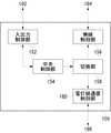
図1は、本実施の形態に係るデータ伝送装置100の構成を示す。この装置は、他のデータ伝送装置100との間で、AV(Audio Visual)データやテキストデータなどの情報信号の無線による送受信処理、すなわち無線データ通信を行う。AVデータは、画像データや音声データを含むデータである。データ伝送装置100は、AV入出力部102と、無線部104と、電灯線通信部106と、機器ID保持部108と、赤外線受光部110と、赤外線送信部112と、認証部114と、暗号部116と、復号部118と、制御部150とを備える。Embodiment 1
FIG. 1 shows a configuration of a
AV入出力部102は、データ伝送装置100外部のAV機器200との間で、AVデータのやりとりを行う。AV機器200は、データ伝送装置100ごとに設けられる。AV機器200は、例えばテレビジョン受像機、ビデオテープレコーダーやレーザーディスクプレーヤを指す。AVデータのやりとりの対象は、上述のAV機器200に限らず、AVデータの認識可能な機器であればよく、例えばパーソナルコンピュータやゲーム機器であってもよい。 The AV input /
無線部104は、探索信号を無線で送出することにより、無線データ通信が可能である他のデータ伝送装置100を探索する。最初の探索処理は、データ伝送装置100の電源プラグ12が図示しないコンセントに差し込まれたとき、すなわち、データ伝送装置100に最初に電力が供給されたときに行われる。以降の探索処理は、データ伝送装置100に電力が供給されている間、所定の時間毎に繰り返し実行される。繰り返し探索処理が行われることで、他のデータ伝送装置100が、現在も無線データ通信が可能な状態にあるか否かを確認することができる。探索処理の後、無線部104は、自身が有するアンテナ10を用いて、後述する認証部114により無線データ通信が許可された他のデータ伝送装置との間で、無線データ通信を行う。 The
電灯線通信部106は、データ伝送装置100の電源プラグ12がコンセントに差し込まれている間、電灯線を利用した閉域のネットワーク(以下、単に「電灯線ネットワーク」という)内にてデータ通信(以下、単に「電灯線データ通信」という)を行う。電灯線通信部106は、電灯線データ通信の際、自身のデータ伝送装置100固有の機器情報である機器IDを他のデータ伝送装置100に送出し、他のデータ伝送装置100の機器IDを他のデータ伝送装置100から取得する。電灯線通信部106は、データ伝送装置100に対応するAV機器200の固有の機器情報、例えば型番やシリアルナンバーをやりとりしてもよい。いずれの場合であっても、機器情報は、他の装置や機器間で重複しないものとする。電灯線通信部106は、電灯線ネットワーク内にて取得した他のデータ伝送装置100の機器IDを、機器ID保持部108に保持する。 The power
赤外線受光部110は、リモートコントローラ16により、ユーザからのAVデータの操作に関する指示を受け付け、その指示を後述の制御部150に送信する。赤外線送信部112は、赤外線受光部110で受け付けたユーザからの指示を、赤外線発光モジュール18を介して、赤外線でAV機器200に送出する。他のAV機器200のAVデータの操作に関する指示であった場合、データ伝送装置100は、無線部104を介して他のAV機器200に対応する他のデータ伝送装置100の無線部104にその指示を転送する。 The infrared
認証部114は、電灯線通信部106により電灯線ネットワーク内にて取得された他のデータ伝送装置の機器IDに基づいて、無線データ通信を許可する他のデータ伝送装置を特定する。具体的には、認証部114は、機器ID保持部108に保持されている他のデータ伝送装置100の機器ID群内に、電灯線データ通信の際に取得された他のデータ伝送装置100の機器IDと同一の機器IDが存在するか否かに応じて、無線データ通信を許可する他のデータ伝送装置100を特定する。認証部114は、無線データ通信を許可する他のデータ伝送装置100を特定する特定部として動作してもよい。 The
無線データ通信はその性質上、同一の電灯線ネットワークに存在しないデータ伝送装置100、例えば隣家のデータ伝送装置100、に対して電波を送る可能性があり、第三者によるなりすましのリスクが高いため、無線データ通信の安全性が高いとは言えないことがある。そのため、機密性の高い閉域の電灯線ネットワークを利用することにより、無線データ通信を許可する相手を特定し、その特定された相手と無線データ通信を行うことは有意義である。 Due to the nature of wireless data communication, there is a possibility that radio waves may be transmitted to the
機器IDは、電灯線ネットワーク内で一意に存在し、機密性の高い閉域の電灯線ネットワークの外部に漏れることは少ない。データ伝送装置100は、そうした機器IDを利用して、無線データ通信を許可する相手を特定することで、同一の電灯線ネットワーク内に存在しないデータ伝送装置との無線データ通信を抑制することができ、無線データ通信の安全性を高めることができる。 The device ID is uniquely present in the power line network and rarely leaks outside the closed power line network with high confidentiality. The
上述のごとく、データ伝送装置100が機器IDのやりとりを行うとき、機密性の高い閉域の電灯線ネットワークを利用するため、機器IDが電灯線ネットワーク外部に漏れることは少ない。そのため、機器ID自体を暗号化する手間を省いたり、その暗号化処理のためのハードウエア規模やソフトウエア規模を削減したりすることができる。 As described above, when the
無線データ通信を許可する相手を特定するとき、データ伝送装置100は、取得した他のデータ伝送装置100の機器IDと機器ID保持部108に格納されている機器ID群とを比較すれば十分である。これにより、比較的簡便な方法で、無線データ通信の安全性を高めることができる。 When identifying a partner to whom wireless data communication is permitted, the
暗号部116は、所定のアルゴリズム、例えばハッシュ関数を用いて、自身のデータ伝送装置100の機器IDに対して一つの共通鍵を生成する。共通鍵生成後、暗号部116は、その共通鍵を用いてAVデータを暗号化する。暗号部116は、電灯線ネットワーク内の、図1では不図示の分電盤の機器IDに対して一つの共通鍵を生成してもよい。暗号部116は、内部に図示しない乱数生成部を設け、その乱数生成部により生成された乱数を機器IDに連結させ、所定のアルゴリズムを施して、一つの共通鍵を生成してもよい。その乱数は分電盤が生成するものであってもよい。その乱数は、現在の日付であってもよい。AVデータを暗号化することで、第三者からの盗聴を抑制することができ、無線データ通信の安全性を高めることができる。 The
復号部118は、共通鍵によって暗号化されたAVデータを、暗号化の際に用いられた、自身のデータ伝送装置100の機器IDをもとに生成された共通鍵を用いて復号化する。 The decrypting
制御部150は、AV入出力部102、無線部104、電灯線通信部106、赤外線受光部110、赤外線送信部112、認証部114、暗号部116および復号部118の各種機能を制御する。制御部150は、AV入出力部102により取得されたAVデータを無線部104に転送したり、無線部104により受信されたAVデータをAV入出力部102に転送したりする。さらに、制御部150は、AV入出力部102により取得されたAVデータを暗号化するよう暗号部116を制御したり、無線部104により受信された暗号化されたAVデータを復号化するよう復号部118を制御したりする。 The
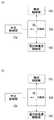
図2は、本実施の形態に係る制御部150の構成を示す。制御部150は、入出力制御部152と、中央制御部154と、無線制御部156と、切換部158と、電灯線通信制御部160とを備える。 FIG. 2 shows a configuration of the
入出力制御部152は、後述の中央制御部154より、他のデータ伝送装置100へのAVデータの伝送指示があったとき、自身のデータ伝送装置100に対応するAV機器200のAVデータを取得するよう、AV入出力部102を制御する。 The input /
無線制御部156は、後述の中央制御部154より、他のデータ伝送装置100へのAVデータの送信指示があったとき、AV入出力部102により取得された自身のデータ伝送装置100のAVデータを、無線で他のデータ伝送装置100に送信するよう、無線部104を制御する。また、リモートコントローラ16を介して、他のAV機器200のAVデータの操作に関するユーザからの指示があったとき、無線制御部156は、赤外線受光部110により受け付けたユーザからの指示を、無線で他のデータ伝送装置100に転送するよう、無線部104を制御する。 The
電灯線通信制御部160は、電灯線データ通信の際、自身のデータ伝送装置100の機器IDを、電灯線ネットワーク内の他のデータ伝送装置100に送信するよう、電灯線通信部106を制御する。 The power line
切換部158は、後述の中央制御部154からの指示にもとづいて、制御信号の出力先を、無線制御部156および電灯線通信制御部160のうち、いずれかに切換える。すなわち、無線データ通信でAVデータをやり取りする場合には、制御信号の出力先を無線制御部156に切換え、電灯線データ通信で機器IDをやり取りする場合には、制御信号の出力先を電灯線通信制御部160に切換える。中央制御部154は、入出力制御部152、無線制御部156、切換部158および電灯線通信制御部160の各種機能を制御する。 The
図3の(a)は、第1のタイミングにおける切換部158内のスイッチSWの切換え状態を示し、図3の(b)は、第2のタイミングにおける切換部158内のスイッチSWの切換え状態を示す。第1のタイミングとは、無線データ通信でAVデータをやりとりする場合を示し、第2のタイミングとは、電灯線データ通信で機器IDをやりとりする場合を示す。図示のごとく、第1のタイミングでは、スイッチSWにより、中央制御部154からの制御信号の出力先が無線制御部156に切換えられているため、無線制御部156の制御が可能になる。同様に、第2のタイミングでは、電灯線通信制御部160の制御が可能になる。 3A shows the switching state of the switch SW in the
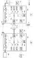
図4は、データ伝送システム40の一例を模式的に示す。データ伝送システム40は、第1電灯線22a〜第3電灯線22c、第1データ伝送装置100a〜第3データ伝送装置100cおよび分電盤20を含む。家屋30の1階部分には、分電盤20、第1データ伝送装置100a、および第1AV機器200a、例えばビデオテープレコーダーが、2階部分には、第2データ伝送装置100b、および第2AV機器200b、例えばテレビジョン受像機が、3階部分には、第3データ伝送装置100c、および第3AV機器200c、例えばテレビジョン受像機が、備えられている。第1データ伝送装置100a〜第3データ伝送装置100cの第1電源プラグ12a〜第3電源プラグ12cは、それぞれ第1コンセント14a〜第3コンセント14cに差し込まれている。 FIG. 4 schematically shows an example of the
分電盤20は、第1データ伝送装置100a〜第3データ伝送装置100cからの、それぞれ、第1電灯線22a〜第3電灯線22cを集合し、それらと外部の電力線24とを電気的に接続する。分電盤20は、第1電灯線22a〜第3電灯線22cを集合させることで、閉域の電灯線ネットワークを構成する。ここで、第1データ伝送装置100a〜第3データ伝送装置100cや第1AV機器200a〜第3AV機器200cを含めて、閉域の電灯線ネットワークと呼んでもよい。分電盤20は、第1データ伝送装置100a〜第3データ伝送装置100c毎の機器IDの外部の電力線24への漏洩を遮断するフィルタを備える。これにより、機密性の高い閉域の電灯線ネットワークを実現でき、安全性の高い無線データ通信を実現できる。 The
図5は、図4における第1データ伝送装置100aと第2データ伝送装置100bとの間の無線データ通信の一例を示す。前述のごとく、第1データ伝送装置100aおよび第1AV機器200aは、1階部分に備えられ、第2データ伝送装置100bおよび第2AV機器200bは、2階部分に備えられている。以下、図1と同等の構成には同じ符号を与え適宜説明を略す。 FIG. 5 shows an example of wireless data communication between the first
リモートコントローラ16によるユーザからの指示により、第2データ伝送装置100b内の第2無線部104bから、第1データ伝送装置100a内の第1無線部104aにAVデータの操作に関する指示が転送される。第1制御部150aは、その指示に基づき、第1データ伝送装置100aの外部に接続された第1AV機器200aにて、AVデータの再生操作を行う。第1AV入出力部102aは、第1AV機器200aにて再生されるAVデータを取得する。第1制御部150aは、第1無線部104aを介して第2無線部104bにAVデータを送る。第2AV入出力部102bは、取得したAVデータを第2AV機器200bに出力する。これにより、1階部分の第1AV機器200aにて再生されるAVデータを2階部分の第2AV機器200bの画面に出力させることができる。 In response to an instruction from the user by the
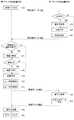
図6は、本実施の形態に係るAVデータの伝送処理の流れを示す。第2データ伝送装置100bの第2無線部104bは、電灯線ネットワーク内に探索信号を送出する(S10)。第1データ伝送装置100aの第1無線部104aは、無線データ通信が可能であれば、第2無線部104bに応答信号を送出する(S12)。 FIG. 6 shows a flow of AV data transmission processing according to the present embodiment. The
第2データ伝送装置100bの第2電灯線通信部106bは、閉域の電灯線ネットワークにて、第1データ伝送装置100aの第1電灯線通信部106aに、自身の機器IDを送出する(S14)。第1認証部114aは、第2電灯線通信部106bから送出された機器IDが新規の機器IDでない場合(S16のN)、第1機器ID保持部108aに保持されている機器ID群と比較する。同一の機器IDが存在すれば、第2データ伝送装置100bからの無線データ通信を許可する(S20)。第2電灯線通信部106bから送出された機器IDが新規のIDであれば(S16のY)、第1電灯線通信部106aは、第2電灯線通信部106bから送出された機器IDを第1機器ID保持部108aに保持し(S18)、第1認証部114aは、第2データ伝送装置100bからの無線データ通信を許可する(S20)。 The second power
第1データ伝送装置100aの第1電灯線通信部106aは、電灯線ネットワークにて、第2データ伝送装置100bの第2電灯線通信部106bに、自身の機器IDを送出する(S22)。第2認証部114bは、第1電灯線通信部106aから送出された機器IDが新規のIDでなければ(S24のN)、第2機器ID保持部108bに保持されている機器ID群と比較する。群中に同一の機器IDが存在すれば、第1データ伝送装置100aからの無線データ通信を許可する(S28)。第1電灯線通信部106aから送出された機器IDが新規のIDであれば(S24のY)、第2電灯線通信部106bは、第1電灯線通信部106aから送出された機器IDを第2機器ID保持部108bに保持し(S26)、第1データ伝送装置100aからの無線データ通信を許可する(S28)。 The first power
第2データ伝送装置100bの第2赤外線受光部110bは、リモートコントローラ16を介して、ユーザからのAVデータの伝送指示を受け付ける(S30)。第2データ伝送装置100bの第2無線部104bは、第2赤外線受光部110bにより受け付けたユーザからのAVデータの伝送指示を、第1データ伝送装置100aの第1無線部104aに送信する(S32)。送信前に、第2データ伝送装置100bの第2無線部104bは、探索処理により、現在でも第1データ伝送装置100aが無線データ通信の可能な状態であるか否かを確認してもよい。 The second infrared
第1データ伝送装置100aの第1暗号部116aは、自身の機器IDをもとに生成された共通鍵でAVデータを暗号化する(S34)。第1データ伝送装置100aの第1無線部104aは、第1暗号部116aにより暗号化されたAVデータを、第2データ伝送装置100bの第2無線部104bに伝送する(S36)。 The
第2データ伝送装置100bの第2復号部118bは、伝送相手の第1データ伝送装置100aの機器IDをもとに生成された共通鍵を用いて、暗号化されたAVデータを復号化する(S38)。第2データ伝送装置100bの第2AV入出力部102bは、第2復号部118bにより復号化されたAVデータを第2AV機器200bに出力する(S40)。 The
実施の形態2
実施の形態2が実施の形態1と異なるのは、無線で上述の探索処理を行うのではなく、電灯線ネットワーク内にて探索処理を行う点である。このとき、電灯線通信部106は、図1における無線部104が有する探索処理機能を備える。Embodiment 2
The second embodiment is different from the first embodiment in that the search process is not performed wirelessly but the search process is performed in the power line network. At this time, the power
電灯線通信部106は、電灯線ネットワーク内での探索処理の際、自身のデータ伝送装置100の機器IDを含む探索信号を送出する。電灯線通信部106は、一定時間内に他のデータ伝送装置100からの応答信号があれば、応答信号に含まれる他のデータ伝送装置100の機器IDを機器ID保持部108に保持する。一定時間内に他のデータ伝送装置100からの応答信号がなかった場合、電灯線通信部106は、応答のないデータ伝送装置100の機器IDを機器ID保持部108に保持された機器ID群から削除する。このように、探索処理を機密性の高い閉域の電灯線ネットワーク内にて行うことで、探索処理の安全性を高めることができる。 The power
図7は、本実施の形態に係るAVデータの伝送処理の流れを示す。第2データ伝送装置100bの第2電灯線通信部106bは、電灯線ネットワーク内に、自身の第2データ伝送装置100bの機器IDを含む探索信号を送出する(S52)。 FIG. 7 shows a flow of AV data transmission processing according to the present embodiment. The second power
第1認証部114aは、第2電灯線通信部106bから送出された機器IDが新規の機器IDでない場合(S54のN)、第1機器ID保持部108aに保持されている機器ID群と比較する。群中に同一の機器IDが存在すれば、第2データ伝送装置100bからの無線データ通信を許可する(S58)。第2電灯線通信部106bから送出された機器IDが新規のIDであれば(S54のY)、第1電灯線通信部106aは、第2電灯線通信部106bから送出された機器IDを第1機器ID保持部108aに保持し(S56)、第1認証部114aは、第2データ伝送装置100bからの無線データ通信を許可する(S58)。 When the device ID transmitted from the second power
第1データ伝送装置100aの第1電灯線通信部106aは、電灯線ネットワーク内にて、第2データ伝送装置100bの第2電灯線通信部106bに、自身の機器IDを送出する(S60)。第2データ伝送装置100bの第2電灯線通信部106bは、一定時間内に機器IDを取得しなかった場合(S62のN)、第2機器ID保持部108bに保持されている機器ID群中の機器IDを削除する(S64)。一定時間内に機器IDを取得した場合(S62のY)、上述の削除は行わない。 The first power
第2認証部114bは、第1電灯線通信部106aから送出された機器IDが新規のIDでなければ(S66のN)、第2機器ID保持部108bに保持されている機器ID群と比較し、群中に同一の機器IDが存在すれば、第1データ伝送装置100aからの無線データ通信を許可する(S70)。第1電灯線通信部106aから送出された機器IDが新規のIDであれば(S66のY)、第2電灯線通信部106bは、第1電灯線通信部106aから送出された機器IDを第2機器ID保持部108bに保持し(S68)、第1データ伝送装置100aからの無線データ通信を許可する(S70)。 If the device ID transmitted from the first power
第2データ伝送装置100bの第2赤外線受光部110bは、リモートコントローラ16を介して、ユーザからのAVデータの伝送指示を受け付ける(S72)。第2データ伝送装置100bの第2無線部104bは、第2赤外線受光部110bにより受け付けたユーザからのAVデータの操作に関する指示を、第1データ伝送装置100aの第1無線部104aに送信する(S74)。送信前に、第2データ伝送装置100bの第2電灯線通信部106bは、探索処理により、現在でも第1データ伝送装置100aが無線データ通信の可能な状態であるか否かを確認してもよい。 The second infrared
第1データ伝送装置100aの第1暗号部116aは、自身の機器IDをもとに生成された共通鍵でAVデータを暗号化する(S76)。第1データ伝送装置100aの第1無線部104aは、第1暗号部116aにより暗号化されたAVデータを、第2データ伝送装置100bの第2無線部104bに伝送する(S78)。 The
第2データ伝送装置100bの第2復号部118bは、伝送相手の第1データ伝送装置100aの機器IDをもとに生成された共通鍵を用いて、暗号化されたAVデータを復号化する(S80)。第2データ伝送装置100bの第2AV入出力部102bは、第2復号部118bにより復号化されたAVデータを第2AV機器200bに出力する(S82)。 The
以上、本発明を実施の形態をもとに説明した。この実施の形態は例示であり、それらの各構成要素や各処理プロセスの組合せにいろいろな変形例が可能なこと、またそうした変形例も本発明の範囲にあることは当業者に理解されるところである。 The present invention has been described based on the embodiments. This embodiment is an exemplification, and it will be understood by those skilled in the art that various modifications can be made to combinations of the respective constituent elements and processing processes, and such modifications are also within the scope of the present invention. is there.
20 分電盤、22a〜22c 第1電灯線〜第3電灯線、24 外部の電力線、40 データ伝送システム、100 データ伝送装置、104 無線部、106 電灯線通信部、108 機器ID保持部、114 認証部。 20 Power distribution board, 22a-22c 1st power line-3rd power line, 24 External power line, 40 Data transmission system, 100 Data transmission device, 104 Wireless part, 106 Power line communication part, 108 Device ID holding part, 114 Authentication department.
Claims (5)
Translated fromJapanese前記取得された他のデータ伝送装置の機器情報に基づいて、無線データ通信を許可する他のデータ伝送装置を特定する認証部と、
前記認証部により特定された他のデータ伝送装置との間で無線データ通信を行う無線部と、
を備えることを特徴とするデータ伝送装置。A power line communication unit that acquires device information of other data transmission devices in a closed network using the power line; and
Based on the acquired device information of the other data transmission device, an authentication unit that identifies another data transmission device that permits wireless data communication;
A wireless unit that performs wireless data communication with another data transmission device identified by the authentication unit;
A data transmission device comprising:
前記認証部は、前記保持部に保持された他のデータ伝送装置の機器情報に基づいて、前記無線データ通信を許可する他のデータ伝送装置を特定することを特徴とする請求項1に記載のデータ伝送装置。A holding unit for holding device information of the other data transmission device;
The said authentication part specifies the other data transmission apparatus which permits the said wireless data communication based on the apparatus information of the other data transmission apparatus hold | maintained at the said holding | maintenance part. Data transmission device.
前記分電装置は、外部の電力線と電気的に接続されており、前記データ伝送装置の機器情報の前記外部の電力線への漏洩を遮断するフィルタを備えることを特徴とするデータ伝送システム。A data transmission system comprising: a plurality of data transmission devices; and a power distribution device that collects a plurality of power lines from the plurality of data transmission devices, wherein the power distribution device and the plurality of power lines form a closed network. There,
The data distribution system, wherein the power distribution device is electrically connected to an external power line, and includes a filter that blocks leakage of device information of the data transmission device to the external power line.
前記取得された他のデータ伝送装置の機器情報に基づいて、無線データ通信を許可する他のデータ伝送装置を特定するステップと、
前記特定された他のデータ伝送装置との間で無線データ通信を行うステップと、
を有することを特徴とするデータ伝送方法。Obtaining device information of other data transmission devices in a closed network using power lines; and
Identifying another data transmission device that permits wireless data communication based on the acquired device information of the other data transmission device;
Performing wireless data communication with the identified other data transmission device;
A data transmission method characterized by comprising:
Priority Applications (1)
| Application Number | Priority Date | Filing Date | Title |
|---|---|---|---|
| JP2004155744AJP2005341094A (en) | 2004-05-26 | 2004-05-26 | Data transmission system, data transmission device, distribution device, and data transmission method |
Applications Claiming Priority (1)
| Application Number | Priority Date | Filing Date | Title |
|---|---|---|---|
| JP2004155744AJP2005341094A (en) | 2004-05-26 | 2004-05-26 | Data transmission system, data transmission device, distribution device, and data transmission method |
Publications (1)
| Publication Number | Publication Date |
|---|---|
| JP2005341094Atrue JP2005341094A (en) | 2005-12-08 |
Family
ID=35494166
Family Applications (1)
| Application Number | Title | Priority Date | Filing Date |
|---|---|---|---|
| JP2004155744AWithdrawnJP2005341094A (en) | 2004-05-26 | 2004-05-26 | Data transmission system, data transmission device, distribution device, and data transmission method |
Country Status (1)
| Country | Link |
|---|---|
| JP (1) | JP2005341094A (en) |
Cited By (12)
| Publication number | Priority date | Publication date | Assignee | Title |
|---|---|---|---|---|
| JP2007215003A (en)* | 2006-02-10 | 2007-08-23 | Canon Inc | Wireless communication device and wireless communication method |
| JP2007251926A (en)* | 2006-03-14 | 2007-09-27 | Samsung Electronics Co Ltd | Group ID distribution method, group ID reception method, authentication apparatus, and PLC apparatus in PLC network |
| JP2008147927A (en)* | 2006-12-08 | 2008-06-26 | Sumitomo Electric Ind Ltd | Device registration method and power line communication device for power line communication |
| JP2009118053A (en)* | 2007-11-05 | 2009-05-28 | Nec Access Technica Ltd | Communication apparatus and communication system |
| JP2009267551A (en)* | 2008-04-23 | 2009-11-12 | Nec Personal Products Co Ltd | Data transmission device, data request device, and data reproduction system |
| US20120147825A1 (en)* | 2010-12-14 | 2012-06-14 | Microsoft Corporation | Direct connection with side channel control |
| US8589991B2 (en) | 2010-12-14 | 2013-11-19 | Microsoft Corporation | Direct connection with side channel control |
| US8923770B2 (en) | 2010-12-09 | 2014-12-30 | Microsoft Corporation | Cognitive use of multiple regulatory domains |
| US8948382B2 (en) | 2010-12-16 | 2015-02-03 | Microsoft Corporation | Secure protocol for peer-to-peer network |
| US8971841B2 (en) | 2010-12-17 | 2015-03-03 | Microsoft Corporation | Operating system supporting cost aware applications |
| US9294545B2 (en) | 2010-12-16 | 2016-03-22 | Microsoft Technology Licensing, Llc | Fast join of peer to peer group with power saving mode |
| US9542203B2 (en) | 2010-12-06 | 2017-01-10 | Microsoft Technology Licensing, Llc | Universal dock for context sensitive computing device |
- 2004
- 2004-05-26JPJP2004155744Apatent/JP2005341094A/ennot_activeWithdrawn
Cited By (26)
| Publication number | Priority date | Publication date | Assignee | Title |
|---|---|---|---|---|
| JP2007215003A (en)* | 2006-02-10 | 2007-08-23 | Canon Inc | Wireless communication device and wireless communication method |
| US8555058B2 (en) | 2006-03-14 | 2013-10-08 | Samsung Electronics Co., Ltd. | Method of distributing group IDs in PLC network, method of receiving group IDs in PLC network, authentication apparatus, and PLC apparatus |
| JP2007251926A (en)* | 2006-03-14 | 2007-09-27 | Samsung Electronics Co Ltd | Group ID distribution method, group ID reception method, authentication apparatus, and PLC apparatus in PLC network |
| JP2008147927A (en)* | 2006-12-08 | 2008-06-26 | Sumitomo Electric Ind Ltd | Device registration method and power line communication device for power line communication |
| JP2009118053A (en)* | 2007-11-05 | 2009-05-28 | Nec Access Technica Ltd | Communication apparatus and communication system |
| JP2009267551A (en)* | 2008-04-23 | 2009-11-12 | Nec Personal Products Co Ltd | Data transmission device, data request device, and data reproduction system |
| US9542203B2 (en) | 2010-12-06 | 2017-01-10 | Microsoft Technology Licensing, Llc | Universal dock for context sensitive computing device |
| US9870028B2 (en) | 2010-12-06 | 2018-01-16 | Microsoft Technology Licensing, Llc | Universal dock for context sensitive computing device |
| US9178652B2 (en) | 2010-12-09 | 2015-11-03 | Microsoft Technology Licensing, Llc | Cognitive use of multiple regulatory domains |
| US9801074B2 (en) | 2010-12-09 | 2017-10-24 | Microsoft Technology Licensing, Llc | Cognitive use of multiple regulatory domains |
| US8923770B2 (en) | 2010-12-09 | 2014-12-30 | Microsoft Corporation | Cognitive use of multiple regulatory domains |
| US9462479B2 (en) | 2010-12-09 | 2016-10-04 | Microsoft Technology Licensing, Llc | Cognitive use of multiple regulatory domains |
| US9450995B2 (en) | 2010-12-14 | 2016-09-20 | Microsoft Technology Licensing, Llc | Direct connection with side channel control |
| US8589991B2 (en) | 2010-12-14 | 2013-11-19 | Microsoft Corporation | Direct connection with side channel control |
| US20120147825A1 (en)* | 2010-12-14 | 2012-06-14 | Microsoft Corporation | Direct connection with side channel control |
| US8792429B2 (en)* | 2010-12-14 | 2014-07-29 | Microsoft Corporation | Direct connection with side channel control |
| US9813466B2 (en) | 2010-12-14 | 2017-11-07 | Microsoft Technology Licensing, Llc | Direct connection with side channel control |
| US10575174B2 (en) | 2010-12-16 | 2020-02-25 | Microsoft Technology Licensing, Llc | Secure protocol for peer-to-peer network |
| US9294545B2 (en) | 2010-12-16 | 2016-03-22 | Microsoft Technology Licensing, Llc | Fast join of peer to peer group with power saving mode |
| US9998522B2 (en) | 2010-12-16 | 2018-06-12 | Microsoft Technology Licensing, Llc | Fast join of peer to peer group with power saving mode |
| US8948382B2 (en) | 2010-12-16 | 2015-02-03 | Microsoft Corporation | Secure protocol for peer-to-peer network |
| US9596220B2 (en) | 2010-12-16 | 2017-03-14 | Microsoft Technology Licensing, Llc | Secure protocol for peer-to-peer network |
| US8971841B2 (en) | 2010-12-17 | 2015-03-03 | Microsoft Corporation | Operating system supporting cost aware applications |
| US9338309B2 (en) | 2010-12-17 | 2016-05-10 | Microsoft Technology Licensing, Llc | Operating system supporting cost aware applications |
| US10044515B2 (en) | 2010-12-17 | 2018-08-07 | Microsoft Technology Licensing, Llc | Operating system supporting cost aware applications |
| US9008610B2 (en) | 2010-12-17 | 2015-04-14 | Microsoft Corporation | Operating system supporting cost aware applications |
Similar Documents
| Publication | Publication Date | Title |
|---|---|---|
| KR100863448B1 (en) | How to Provide Security on Powerline Modem Networks | |
| CN102687483B (en) | The provisional registration of equipment | |
| US7689825B2 (en) | Systems and methods for device registration using optical transmission | |
| CN102387501B (en) | Secure wireless link between two devices using probes | |
| CN1682491B (en) | Local terminal device and communication system | |
| JP5768548B2 (en) | WIRELESS COMMUNICATION SYSTEM AND TERMINAL DEVICE AUTHENTICATION METHOD IN WIRELESS COMMUNICATION SYSTEM | |
| US6703923B2 (en) | Apparatus for providing security on a powerline-modem network | |
| EP3058694B1 (en) | Establishing a secure connection between a master device and a slave device | |
| KR101297648B1 (en) | Authentication method between server and device | |
| KR20010080072A (en) | Key exchange via a portable remote control device | |
| JP2005341094A (en) | Data transmission system, data transmission device, distribution device, and data transmission method | |
| US20050216738A1 (en) | Radio transmission device, mutual authentication method and mutual authentication program | |
| JP2004214976A (en) | AV data transmitting device, AV data receiving device, AV data wireless communication system, and electronic device | |
| JP5991051B2 (en) | Wireless communication system, terminal device and program | |
| JP2005244345A (en) | Wireless communication system, wireless communication method, and wireless communication terminal | |
| CN116566714A (en) | Intelligent house data transmission method and system | |
| JP3975364B2 (en) | Home network system | |
| CN112449406B (en) | System and method for assisting in adding a new node to a wireless RF network | |
| JP2005318528A (en) | Radio transmission device, mutual authentication method and mutual authentication program | |
| JP2004214971A (en) | AV data transmitting device, AV data receiving device, and AV data wireless communication system | |
| CN215734303U (en) | Internet of things system and internet of things safety box | |
| CN119341746B (en) | Quantum key-based communication method and related equipment | |
| JP2005286595A (en) | Radio transmission apparatus, mutual authentication method, and mutual authentication program | |
| JP4225822B2 (en) | ENCRYPTED CODE MANAGEMENT SYSTEM, DATA PROCESSING DEVICE, ELECTRONIC DEVICE, AND ENCRYPTED CODE DISTRIBUTION METHOD | |
| JP2014239374A (en) | Radio communication system, radio master unit, radio apparatus and radio communication method |
Legal Events
| Date | Code | Title | Description |
|---|---|---|---|
| A621 | Written request for application examination | Free format text:JAPANESE INTERMEDIATE CODE: A621 Effective date:20061109 | |
| A761 | Written withdrawal of application | Free format text:JAPANESE INTERMEDIATE CODE: A761 Effective date:20070730 |