JP2005337573A - Heat exchanger - Google Patents
Heat exchangerDownload PDFInfo
- Publication number
- JP2005337573A JP2005337573AJP2004156382AJP2004156382AJP2005337573AJP 2005337573 AJP2005337573 AJP 2005337573AJP 2004156382 AJP2004156382 AJP 2004156382AJP 2004156382 AJP2004156382 AJP 2004156382AJP 2005337573 AJP2005337573 AJP 2005337573A
- Authority
- JP
- Japan
- Prior art keywords
- pipe
- heat exchanger
- plate
- end plate
- connection plate
- Prior art date
- Legal status (The legal status is an assumption and is not a legal conclusion. Google has not performed a legal analysis and makes no representation as to the accuracy of the status listed.)
- Pending
Links
- 238000003780insertionMethods0.000claimsabstractdescription51
- 230000037431insertionEffects0.000claimsabstractdescription51
- 238000005219brazingMethods0.000claimsabstractdescription12
- 239000012530fluidSubstances0.000claimsabstractdescription7
- 239000000463materialSubstances0.000claimsdescription10
- 230000002093peripheral effectEffects0.000claimsdescription7
- 210000000078clawAnatomy0.000description2
- 238000000034methodMethods0.000description2
- 230000001737promoting effectEffects0.000description2
- 230000015572biosynthetic processEffects0.000description1
- 239000003507refrigerantSubstances0.000description1
- 230000008961swellingEffects0.000description1
- 239000013585weight reducing agentSubstances0.000description1
Images


Classifications
- F—MECHANICAL ENGINEERING; LIGHTING; HEATING; WEAPONS; BLASTING
- F28—HEAT EXCHANGE IN GENERAL
- F28D—HEAT-EXCHANGE APPARATUS, NOT PROVIDED FOR IN ANOTHER SUBCLASS, IN WHICH THE HEAT-EXCHANGE MEDIA DO NOT COME INTO DIRECT CONTACT
- F28D1/00—Heat-exchange apparatus having stationary conduit assemblies for one heat-exchange medium only, the media being in contact with different sides of the conduit wall, in which the other heat-exchange medium is a large body of fluid, e.g. domestic or motor car radiators
- F28D1/02—Heat-exchange apparatus having stationary conduit assemblies for one heat-exchange medium only, the media being in contact with different sides of the conduit wall, in which the other heat-exchange medium is a large body of fluid, e.g. domestic or motor car radiators with heat-exchange conduits immersed in the body of fluid
- F28D1/03—Heat-exchange apparatus having stationary conduit assemblies for one heat-exchange medium only, the media being in contact with different sides of the conduit wall, in which the other heat-exchange medium is a large body of fluid, e.g. domestic or motor car radiators with heat-exchange conduits immersed in the body of fluid with plate-like or laminated conduits
- F28D1/0308—Heat-exchange apparatus having stationary conduit assemblies for one heat-exchange medium only, the media being in contact with different sides of the conduit wall, in which the other heat-exchange medium is a large body of fluid, e.g. domestic or motor car radiators with heat-exchange conduits immersed in the body of fluid with plate-like or laminated conduits the conduits being formed by paired plates touching each other
- F28D1/0325—Heat-exchange apparatus having stationary conduit assemblies for one heat-exchange medium only, the media being in contact with different sides of the conduit wall, in which the other heat-exchange medium is a large body of fluid, e.g. domestic or motor car radiators with heat-exchange conduits immersed in the body of fluid with plate-like or laminated conduits the conduits being formed by paired plates touching each other the plates having lateral openings therein for circulation of the heat-exchange medium from one conduit to another
- F28D1/0333—Heat-exchange apparatus having stationary conduit assemblies for one heat-exchange medium only, the media being in contact with different sides of the conduit wall, in which the other heat-exchange medium is a large body of fluid, e.g. domestic or motor car radiators with heat-exchange conduits immersed in the body of fluid with plate-like or laminated conduits the conduits being formed by paired plates touching each other the plates having lateral openings therein for circulation of the heat-exchange medium from one conduit to another the plates having integrated connecting members
- F—MECHANICAL ENGINEERING; LIGHTING; HEATING; WEAPONS; BLASTING
- F28—HEAT EXCHANGE IN GENERAL
- F28F—DETAILS OF HEAT-EXCHANGE AND HEAT-TRANSFER APPARATUS, OF GENERAL APPLICATION
- F28F9/00—Casings; Header boxes; Auxiliary supports for elements; Auxiliary members within casings
- F28F9/02—Header boxes; End plates
- F28F9/0246—Arrangements for connecting header boxes with flow lines
- F28F9/0256—Arrangements for coupling connectors with flow lines
Landscapes
- Engineering & Computer Science (AREA)
- Physics & Mathematics (AREA)
- Thermal Sciences (AREA)
- Mechanical Engineering (AREA)
- General Engineering & Computer Science (AREA)
- Heat-Exchange Devices With Radiators And Conduit Assemblies (AREA)
- Details Of Heat-Exchange And Heat-Transfer (AREA)
Abstract
Description
Translated fromJapanese本発明は、チューブとフィンとが交互に積層され、最外層に設けられたエンドプレート側に入口パイプおよび/または出口パイプが接続されるタイプの熱交換器に関する。 The present invention relates to a heat exchanger of a type in which tubes and fins are alternately laminated, and an inlet pipe and / or an outlet pipe are connected to an end plate provided on the outermost layer.
従来から、チューブとフィンとが交互に積層され、最外層に設けられたエンドプレート側に入口パイプ、出口パイプが接続されるタイプの熱交換器はよく知られている(特許文献1)。このような熱交換器においてはエンドプレートに、パイプ接続用プレートを接合し、該パイプ接続用プレートに形成されたバール部に入口パイプおよび出口パイプが挿入されるようになっている。 Conventionally, a heat exchanger in which tubes and fins are alternately stacked and an inlet pipe and an outlet pipe are connected to an end plate provided on the outermost layer is well known (Patent Document 1). In such a heat exchanger, a pipe connection plate is joined to an end plate, and an inlet pipe and an outlet pipe are inserted into a bar portion formed on the pipe connection plate.
しかし、特許文献1のような熱交換器においては、パイプ接続用プレートにバーリング加工を施しバール部を形成する必要があるため、パイプ接続用プレートを構成するプレートは、バール部を形成する分を見込んで大型のものを準備する必要がある。とくに熱交換器の幅方向(空気通過方向)に対しては十分な寸法が確保されないとバーリング加工が困難になるおそれがある。このため、パイプ接続用プレートの大型化により装置の大型化、重量増加を招来するおそれがある。また、このような熱交換器は、各部材を仮組みした後その状態で炉中において一括ろう付けされるが、バール部と入口パイプおよび出口パイプの接続部に、ろう材を介装させて両者を接続させたのでは、仮組み時等においてろう材が位置ずれ等した場合にはろう付け性が低下するおそれもある。
そこで本発明の課題は、パイプ接続用プレートの小型化により、装置の小型化、軽量化を促進しつつ、しかもパイプ接続用プレートとパイプとのろう付け性を向上可能な熱交換器を提供することにある。 Accordingly, an object of the present invention is to provide a heat exchanger capable of improving the brazing property between a pipe connection plate and a pipe while promoting the reduction in size and weight of the apparatus by downsizing the pipe connection plate. There is.
上記課題を解決するために、本発明に係る熱交換器は、チューブとフィンとが交互に積層され、該積層方向の最外層のエンドプレート側に流体の入口パイプと出口パイプとが接続される熱交換器において、前記エンドプレートに、入口パイプ、出口パイプの少なくとも一方が挿入されるとともに、該パイプの挿入側の端部を仮固定可能なパイプ挿入孔が穿設されたパイプ接続用プレートを設けたことを特徴とするものからなる。このような構成においては、パイプ接続用プレートには、入口パイプ、出口パイプの少なくとも一方が挿入されるとともに、該パイプの挿入側の端部を仮固定可能なパイプ挿入孔が穿設されているので、従来のようなバール部および別部材としてのろう材を廃止し、パイプ挿入孔にパイプの先端を挿入するだけで、パイプ挿入孔の周縁に、入口パイプおよび/または出口パイプ(以下単に、パイプと言うこともある。)の端部外面を仮固定でき、炉中において一括ろう付けできる。したがって、パイプ接続用プレートとパイプとを強固にしかも確実に接合できる。また、パイプ接続用プレートにバール部を形成する必要はなくなるので、パイプ接続用プレートを構成するプレート自身を従来に比べ小型化、軽量化できるので、その分装置の小型化、軽量化が促進される。 In order to solve the above problems, in the heat exchanger according to the present invention, tubes and fins are alternately stacked, and an inlet pipe and an outlet pipe of a fluid are connected to the end plate side of the outermost layer in the stacking direction. In the heat exchanger, a pipe connection plate in which at least one of an inlet pipe and an outlet pipe is inserted into the end plate, and a pipe insertion hole capable of temporarily fixing an end portion on the insertion side of the pipe is formed. It consists of what is provided. In such a configuration, at least one of the inlet pipe and the outlet pipe is inserted into the pipe connection plate, and a pipe insertion hole capable of temporarily fixing the end portion on the insertion side of the pipe is formed. Therefore, the conventional bar part and the brazing material as a separate member are abolished, and the inlet pipe and / or the outlet pipe (hereinafter simply referred to as the pipe insertion hole) are simply inserted into the pipe insertion hole at the periphery of the pipe insertion hole. The outer surface of the end of the pipe may be temporarily fixed and can be brazed together in the furnace. Accordingly, the pipe connecting plate and the pipe can be firmly and reliably joined. In addition, since there is no need to form a bar portion on the pipe connection plate, the plate itself constituting the pipe connection plate can be made smaller and lighter than before, so that downsizing and weight reduction of the device are promoted accordingly. The
上記パイプ接続用プレートの表面にはろう材が被覆されていることが好ましい。つまり、パイプ接続用プレートはクラッド材から構成されることが好ましい。パイプ接続用プレートをクラッド材から構成すれば、該パイプ接続用プレートとエンドプレートおよび入口パイプおよび/または出口パイプとを容易にしかも確実にろう付けすることができる。たとえば、エンドプレートとパイプ接続用プレートとを係合する係合機構を設け、パイプ接続用プレートとエンドプレートとを仮固定しつつ、パイプの先端をパイプ挿入孔の周縁にかしめて仮固定すれば、パイプ接続用プレートとエンドプレートおよびパイプとを互いに正しい姿勢で確実にろう付けできる。 The surface of the pipe connecting plate is preferably covered with a brazing material. That is, it is preferable that the pipe connection plate is made of a clad material. If the pipe connecting plate is made of a clad material, the pipe connecting plate, the end plate, the inlet pipe and / or the outlet pipe can be easily and reliably brazed. For example, if an engagement mechanism that engages the end plate and the pipe connection plate is provided and the pipe connection plate and the end plate are temporarily fixed, the tip of the pipe is temporarily fixed to the periphery of the pipe insertion hole. The pipe connecting plate, the end plate and the pipe can be reliably brazed in the correct posture.
また、パイプ挿入孔の周縁をテーパ状または段状に形成すれば、パイプ挿入孔にパイプ挿入側の端部を挿入し、たとえば該端部を拡径することにより、パイプ接続用プレートに対しパイプ挿入側の端部を強固に仮固定することができる。また、パイプ接続用プレートのパイプ挿入孔にパイプ挿入側の端部を圧入して両者を仮固定するようにしてもよい。 Further, if the periphery of the pipe insertion hole is formed in a taper shape or a stepped shape, an end portion on the pipe insertion side is inserted into the pipe insertion hole, for example, by expanding the diameter of the end portion, the pipe connection plate is connected The end on the insertion side can be temporarily fixed firmly. Alternatively, the end of the pipe insertion side may be press-fitted into the pipe insertion hole of the pipe connection plate to temporarily fix them.
上記パイプの挿入側の端部は、パイプ接続用プレートのエンドプレートへの接続面と面一若しくは該接続面より内側に配置されていることが好ましい。このような構成にすれば、パイプ接続用プレートのエンドプレートへの接続面の全体を、容易にしかも確実にエンドプレートにろう付けできる。 It is preferable that the end portion on the insertion side of the pipe is disposed flush with the connection surface to the end plate of the pipe connection plate or inside the connection surface. With this configuration, the entire connection surface of the pipe connection plate to the end plate can be easily and reliably brazed to the end plate.
上記パイプ接続用プレートのエンドプレート幅方向に対する寸法は、エンドプレートの幅方向の寸法以下に形成されていることが好ましい。このようにすれば、パイプ接続用プレートがエンドプレートの幅方向に突出することはなくなるので、仮組みされた熱交換器を炉中において水平に載置しろう付けすることが可能になる。 It is preferable that a dimension of the pipe connecting plate with respect to the end plate width direction is not more than a dimension of the end plate width direction. In this way, the pipe connection plate does not protrude in the width direction of the end plate, so that the temporarily assembled heat exchanger can be placed horizontally and brazed in the furnace.
上記パイプ接続用プレートのパイプの挿入側の面は、エンドプレートの最外層のフィンが接合される部分の外面と実質的に面一になるよう設けられることが好ましい。ろう付け時においては、仮組みされた熱交換器は積層方向の両側から治具で挟持されるが、上記のように構成すれば治具の形状を簡素化することができる。 It is preferable that the pipe insertion side surface of the pipe connection plate is provided so as to be substantially flush with the outer surface of the portion of the end plate to which the fin of the outermost layer is joined. At the time of brazing, the temporarily assembled heat exchanger is sandwiched by jigs from both sides in the stacking direction. However, if configured as described above, the shape of the jig can be simplified.
このように、本発明に係る熱交換器によれば、パイプ接続用プレートひいては装置の小型化、軽量化を促進しつつ、パイプ接続用プレートとパイプとのろう付け性を向上できる。 As described above, according to the heat exchanger according to the present invention, it is possible to improve the brazability between the pipe connection plate and the pipe while promoting the reduction in size and weight of the pipe connection plate and thus the apparatus.
以下に、本発明に係る熱交換器の望ましい実施の形態について、図面を参照しながら説明する。
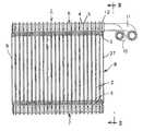
図1ないし図10は、本発明の一実施態様に係る熱交換器を示している。図において、1は熱交換器を示している。熱交換器1は、チューブ2とフィン3とが交互に積層された積層型熱交換器を示している。チューブ2は、チューブ形成用プレート4、5を互いに接合したものから形成されており、内部には流体(たとえば、冷媒)の流路(図示略)が形成されている。そして、積層されたチューブ2の長手方向の両端には、タンク6、7が形成されるようになっている。タンク6、7はチューブ2を介して互いに連通されている。Hereinafter, preferred embodiments of a heat exchanger according to the present invention will be described with reference to the drawings.
1 to 10 show a heat exchanger according to an embodiment of the present invention. In the figure,
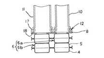
チューブ2とフィン3との積層方向の最外層には、図5に示すようなエンドプレート8、9が設けられている。
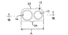
エンドプレート8には、流体を熱交換器1内へ導入する入口パイプ10と熱交換器1から流体を導出するための出口パイプ11とが接続されるパイプ接続用プレート12が接合(ろう付け)されている。パイプ接続用プレート12には、入口パイプ10が挿入されるパイプ挿入孔13と、出口パイプ11が挿入されるパイプ挿入孔14とが穿設されている。エンドプレート8の挿入孔13、14に対応する位置には孔15、16が設けられている。そして、入口パイプ10はタンク6の入口タンク6a側に、一方、出口パイプ11は出口タンク6b側に連通されている。 A
パイプ接続用プレート12の挿入孔13、14の周縁は、図7に示すようにパイプの挿入側の面17からエンドプレートへの接続面18に向かって拡径されるテーパ状に形成されている。なお、パイプ接続用プレート12の挿入孔13、14の周縁は図9、図10に示すように段部28、29を有する段状に形成してもよい。また、パイプ接続用プレート12はクラッド材から構成されている。また、図2、図3に示すようにパイプ接続用プレート12の幅方向に対する寸法Aは、エンドプレートの幅方向の寸法B以下に形成されている As shown in FIG. 7, the peripheral edges of the
熱交換器1は、各部材を仮組み状態(アッセンブリ状態)にし、そして、仮組みされた熱交換器を炉中においてろう付けすることにより、各部材が一括してろう付けされるようになっている。本実施態様においては、パイプ接続用プレート12、パイプ10、11は、図8に示すようにして互いに仮組みされるようになっている。まず、パイプ10、11にバルジ加工を施し、膨出部19、20を形成する(図8(a))。次に、パイプ10、11をパイプ接続用プレート12のパイプの挿入側の面17から挿入孔13、14に挿入するとともに、パイプ10,11の端部をテーパ状に形成される挿入孔13、14の周縁にかしめる(図8(b))。この際、パイプ10,11の端部は、パイプ接続用プレート12のエンドプレートへの接続面18より内側に(本実施態様においては、面18と略面一に)配置されるようになっている。なお、パイプ10,11のパイプ接続用プレート12の挿入孔13、14への挿入代は膨出部19、20により一定量に制限されるようになっている。そして、パイプ10,11が仮固定されたパイプ接続用プレート12をエンドプレート8のパイプ接続用プレート12の接合部21に係合させ仮固定する(図8(c))。該仮固定は、パイプ接続用プレート12の切り欠き22に、エンドプレート8の爪23を係合またはかしめるとともに、パイプ接続用プレート12の突起24をエンドプレート8の長穴25に挿入することに行われるようになっている。このようにして、エンドプレート8とパイプ接続用プレート12との係合機構26が構成されている。 In the
係合機構26により、エンドプレート8にパイプ接続用プレート12を係合させ仮固定した際には、図4に示すようにパイプ接続用プレート12のパイプの挿入側の面17とエンドプレート8の最外層のフィン3が接合される部分の外面27とは略面一になるようになっている。 When the
本実施態様においては、パイプ接続用プレート12には、入口パイプ10、出口パイプ11が挿入されるとともに、該パイプの挿入側の端部を仮固定可能なパイプ挿入孔13、14が穿設されているので、従来のようなバール部および別部材としてのろう材を廃止し、パイプ挿入孔13、14にパイプの先端を挿入するだけで、パイプ挿入孔の周縁に、パイプの端部外面を仮固定でき、炉中において一括ろう付けできる。したがって、パイプ接続用プレート12とパイプ10、11とを強固にしかも確実に接合できる。また、パイプ接続用プレート12にバール部を形成する必要はなくなるので、パイプ接続用プレート12を構成するプレート自身を従来に比べ小型化、軽量化できるので、その分装置の小型化、軽量化が促進される。 In the present embodiment, the
また、パイプ接続用プレート12はクラッド材から構成されるので、該パイプ接続用プレート12とエンドプレート8およびパイプ10,11とを容易にしかも確実にろう付けすることができる。また、エンドプレート8とパイプ接続用プレート12とは係合機構26により強固にしかも確実に仮固定される。したがって、パイプ10、11の挿入側の端部をパイプ挿入孔13,14の周縁にかしめて仮固定すれば、パイプ接続用プレートとエンドプレートおよびパイプとを互いに正しい姿勢で確実にろう付けできる。 Further, since the
パイプ挿入孔13、14の周縁はテーパ状または段状に形成されているので、パイプ挿入孔13、14にパイプ挿入側の端部を挿入し、たとえば該端部を拡径することにより、パイプ接続用プレート12に対しパイプ挿入側の端部をより強固に仮固定することができる。なお、上述のようにパイプ接続用プレート12のパイプ挿入孔13、14にパイプ挿入側の端部を圧入して両者を仮固定することも可能である。 Since the peripheral edges of the pipe insertion holes 13 and 14 are formed in a taper shape or stepped shape, the pipe insertion side ends are inserted into the pipe insertion holes 13 and 14, for example, by expanding the diameters of the end portions. The end on the pipe insertion side can be temporarily fixed to the
また、パイプの挿入側の端部は、パイプ接続用プレート12のエンドプレートへの接続面18と面一若しくは該接続面18より内側に配置されているので、パイプ接続用プレート12のエンドプレートへの接続面18の全体を、容易にしかも確実にエンドプレート8の接合部21にろう付けできる。 Further, the end of the pipe insertion side is arranged flush with or inside the
また、パイプ接続用プレート12のエンドプレート幅方向に対する寸法Aは、エンドプレートの幅方向の寸法B以下に形成されているので、パイプ接続用プレート12がエンドプレートの幅方向に突出することはなくなる。したがって、仮組みされた熱交換器を炉中において水平に載置しろう付けすることが可能になりろう付け性を一層向上できる。 Further, since the dimension A with respect to the end plate width direction of the
また、パイプ接続用プレート12のパイプの挿入側の面17は、エンドプレート8の最外層のフィンが接合される部分の外面27と実質的に面一になるよう設けられるので、仮組みされた熱交換器を積層方向の両側から挟持する治具の形状を簡素化することができる。 Further, the pipe
本発明は、たとえばチューブとフィンとが交互に積層され、最外層に設けられたエンドプレート側に入口パイプおよび/または出口パイプが接続されるタイプの熱交換器に広く適用でき、該熱交換器は車両用の熱交換器として好適である。 The present invention can be widely applied to, for example, a type of heat exchanger in which tubes and fins are alternately stacked and an inlet pipe and / or an outlet pipe are connected to an end plate provided on the outermost layer. Is suitable as a heat exchanger for vehicles.
1 熱交換器
2 チューブ
3 フィン
4、5 チューブ形成用プレート
6、7 タンク
6a 入口タンク
6b 出口タンク
8、9 エンドプレート
10 入口パイプ
11 出口パイプ
12 パイプ接続用プレート
13、14 挿入孔
15、16 孔
17 パイプの挿入側の面
18 エンドプレートへの接続面
19、20 膨出部
21 接合部
22 切り欠き
23 爪
24 突起
25 長穴
26 係合機構
27 外面
28、29 段部DESCRIPTION OF
Claims (9)
Translated fromJapanesePriority Applications (6)
| Application Number | Priority Date | Filing Date | Title |
|---|---|---|---|
| JP2004156382AJP2005337573A (en) | 2004-05-26 | 2004-05-26 | Heat exchanger |
| EP05253034AEP1600719A3 (en) | 2004-05-26 | 2005-05-18 | Stacking-type, multi-flow, heat exchangers and methods for manufacturing such heat exchangers |
| MYPI20052350AMY138182A (en) | 2004-05-26 | 2005-05-24 | Stacking-type, multi-flow, heat exchangers and methods for manufacturing such heat exchangers |
| US11/135,370US7311138B2 (en) | 2004-05-26 | 2005-05-24 | Stacking-type, multi-flow, heat exchangers and methods for manufacturing such heat exchangers |
| CN200510075951.6ACN1707214A (en) | 2004-05-26 | 2005-05-26 | Stacking-type, multi-flow, heat exchangers and methods for manufacturing such heat exchangers |
| CA002508409ACA2508409A1 (en) | 2004-05-26 | 2005-05-26 | Stacking-type, multi-flow, heat exchangers and methods for manufacturing such heat exchangers |
Applications Claiming Priority (1)
| Application Number | Priority Date | Filing Date | Title |
|---|---|---|---|
| JP2004156382AJP2005337573A (en) | 2004-05-26 | 2004-05-26 | Heat exchanger |
Publications (1)
| Publication Number | Publication Date |
|---|---|
| JP2005337573Atrue JP2005337573A (en) | 2005-12-08 |
Family
ID=34941352
Family Applications (1)
| Application Number | Title | Priority Date | Filing Date |
|---|---|---|---|
| JP2004156382APendingJP2005337573A (en) | 2004-05-26 | 2004-05-26 | Heat exchanger |
Country Status (6)
| Country | Link |
|---|---|
| US (1) | US7311138B2 (en) |
| EP (1) | EP1600719A3 (en) |
| JP (1) | JP2005337573A (en) |
| CN (1) | CN1707214A (en) |
| CA (1) | CA2508409A1 (en) |
| MY (1) | MY138182A (en) |
Cited By (3)
| Publication number | Priority date | Publication date | Assignee | Title |
|---|---|---|---|---|
| JP2007247891A (en)* | 2006-02-17 | 2007-09-27 | Denso Corp | Pipe joint device, pipe joint structure of heat exchanger and installation method of pipe for heat exchanger |
| KR20160032106A (en)* | 2013-07-19 | 2016-03-23 | 발레오 시스템므 떼르미끄 | Heat exchanger with an adapter unit fixed to an endplate, and associated method of manufacture |
| JP2023001419A (en)* | 2021-06-21 | 2023-01-06 | パナソニックIpマネジメント株式会社 | Heat exchanger and refrigeration system using the same |
Families Citing this family (7)
| Publication number | Priority date | Publication date | Assignee | Title |
|---|---|---|---|---|
| JP2006010102A (en)* | 2004-06-22 | 2006-01-12 | Sanden Corp | Stacked heat exchanger and its manufacturing method |
| DE102006044091A1 (en)* | 2006-09-20 | 2008-04-03 | Carl Zeiss Microimaging Gmbh | Control module and control system for influencing sample environment parameters of an incubation system, method for controlling a microscope assembly and computer program product |
| US7926854B2 (en)* | 2008-10-10 | 2011-04-19 | Denso International America, Inc. | Pipe joint block for fluid transfer |
| USD624166S1 (en)* | 2009-03-04 | 2010-09-21 | De'longhi Spa | Electric oil filled radiator |
| JP2012141096A (en)* | 2010-12-28 | 2012-07-26 | Mitsubishi Heavy Ind Ltd | Method for manufacturing hot-water heater, and hot-water heater manufactured thereby |
| USD834161S1 (en)* | 2016-02-08 | 2018-11-20 | Tomton S.R.O. | Heat exchanger |
| CN109286276B (en)* | 2017-07-20 | 2020-09-29 | 东芝三菱电机产业系统株式会社 | Totally enclosed rotating electrical machine, tube sheet structure, and method for manufacturing tube sheet structure |
Family Cites Families (41)
| Publication number | Priority date | Publication date | Assignee | Title |
|---|---|---|---|---|
| US484696A (en)* | 1892-10-18 | Henry benbow | ||
| US173101A (en)* | 1876-02-01 | Improvement in oil-stoves | ||
| US4487038A (en)* | 1982-04-12 | 1984-12-11 | Diesel Kiki Co., Ltd. | Laminate type evaporator |
| GB2167699B (en)* | 1984-12-04 | 1988-04-27 | Sanden Corp | A method for producing a heat exchanger |
| JPS6246195A (en)* | 1985-08-22 | 1987-02-28 | Diesel Kiki Co Ltd | Lamination type heat exchanger |
| JPH069738Y2 (en)* | 1987-01-23 | 1994-03-16 | 株式会社ゼクセル | Brazing structure of pipe material |
| JP2560340B2 (en)* | 1987-08-27 | 1996-12-04 | 日本電装株式会社 | Stacked heat exchanger |
| FR2625172B1 (en)* | 1987-12-24 | 1990-04-20 | Apple Computer France | PACKAGING WITH AIR BAGS |
| JPH0619965Y2 (en) | 1988-01-22 | 1994-05-25 | サンデン株式会社 | Heat exchanger |
| US5088193A (en)* | 1988-09-02 | 1992-02-18 | Sanden Corporation | Method for manufacturing a heat exchanger |
| US5148429A (en) | 1988-10-27 | 1992-09-15 | Kabushiki Kaisha Toshiba | Voice data transmission system and method |
| US5099576A (en)* | 1989-08-29 | 1992-03-31 | Sanden Corporation | Heat exchanger and method for manufacturing the heat exchanger |
| US5172762A (en)* | 1989-10-20 | 1992-12-22 | Sanden Corporation | Heat exchanger |
| JPH03199897A (en)* | 1989-12-27 | 1991-08-30 | Toyo Radiator Co Ltd | Structure of tube for heat exchanger |
| US5119552A (en)* | 1990-02-16 | 1992-06-09 | Sanden Corporation | Method for manufacturing header pipe of heat exchanger |
| JP2513332Y2 (en)* | 1990-02-22 | 1996-10-02 | サンデン株式会社 | Heat exchanger |
| US5214847A (en)* | 1990-03-07 | 1993-06-01 | Sanden Corporation | Method for manufacturing a heat exchanger |
| US5174373A (en)* | 1990-07-13 | 1992-12-29 | Sanden Corporation | Heat exchanger |
| JPH04177094A (en)* | 1990-11-13 | 1992-06-24 | Sanden Corp | Laminated type heat exchanger |
| CA2568984C (en) | 1991-06-11 | 2007-07-10 | Qualcomm Incorporated | Variable rate vocoder |
| US5255672A (en)* | 1991-08-07 | 1993-10-26 | Jinotti Walter J | Dual-purpose catheter assembly |
| JPH0646080A (en) | 1992-07-22 | 1994-02-18 | Toshiba Corp | Delay fluctuation absorption control method |
| JPH06129791A (en)* | 1992-10-15 | 1994-05-13 | Sanden Corp | Heat exchanger and method for fixing bracket thereof |
| JPH0755384A (en)* | 1993-08-19 | 1995-03-03 | Sanden Corp | Multi-tube heat exchanger |
| US5632331A (en)* | 1993-09-30 | 1997-05-27 | Sanden Corporation | Heat exchanger |
| US5513700A (en)* | 1994-07-29 | 1996-05-07 | Ford Motor Company | Automotive evaporator manifold |
| JPH0886536A (en)* | 1994-09-14 | 1996-04-02 | Zexel Corp | Expansion valve mounting member |
| JPH08327281A (en)* | 1995-05-30 | 1996-12-13 | Sanden Corp | Header for heat exchanger |
| JPH08327276A (en)* | 1995-05-30 | 1996-12-13 | Sanden Corp | Multi-tube type heat exchanger |
| JP3393957B2 (en)* | 1995-05-30 | 2003-04-07 | サンデン株式会社 | Heat exchanger fluid supply / drain pipe joining method |
| JP3530660B2 (en)* | 1995-12-14 | 2004-05-24 | サンデン株式会社 | Heat exchanger tank structure |
| JPH09280781A (en)* | 1996-04-17 | 1997-10-31 | Sanden Corp | Multitubular heat exchanger |
| JPH10185463A (en)* | 1996-12-19 | 1998-07-14 | Sanden Corp | Heat-exchanger |
| JP3593434B2 (en)* | 1997-02-06 | 2004-11-24 | サンデン株式会社 | Heat exchanger unit |
| JP3912836B2 (en)* | 1997-02-21 | 2007-05-09 | サンデン株式会社 | Heat exchanger |
| JP3959834B2 (en)* | 1998-03-30 | 2007-08-15 | 株式会社デンソー | Stacked heat exchanger |
| JP4153106B2 (en)* | 1998-10-23 | 2008-09-17 | サンデン株式会社 | Heat exchanger |
| JP4328445B2 (en)* | 2000-03-01 | 2009-09-09 | 昭和電工株式会社 | Stacked heat exchanger |
| JP2001289589A (en)* | 2000-04-06 | 2001-10-19 | Sanden Corp | Pipe connecting structure of heat exchanger |
| JP4077610B2 (en)* | 2001-03-16 | 2008-04-16 | カルソニックカンセイ株式会社 | Housingless oil cooler |
| JP4426328B2 (en) | 2004-02-06 | 2010-03-03 | サンデン株式会社 | Laminate heat exchanger |
- 2004
- 2004-05-26JPJP2004156382Apatent/JP2005337573A/enactivePending
- 2005
- 2005-05-18EPEP05253034Apatent/EP1600719A3/ennot_activeWithdrawn
- 2005-05-24MYMYPI20052350Apatent/MY138182A/enunknown
- 2005-05-24USUS11/135,370patent/US7311138B2/ennot_activeExpired - Lifetime
- 2005-05-26CNCN200510075951.6Apatent/CN1707214A/enactivePending
- 2005-05-26CACA002508409Apatent/CA2508409A1/ennot_activeAbandoned
Cited By (5)
| Publication number | Priority date | Publication date | Assignee | Title |
|---|---|---|---|---|
| JP2007247891A (en)* | 2006-02-17 | 2007-09-27 | Denso Corp | Pipe joint device, pipe joint structure of heat exchanger and installation method of pipe for heat exchanger |
| KR20160032106A (en)* | 2013-07-19 | 2016-03-23 | 발레오 시스템므 떼르미끄 | Heat exchanger with an adapter unit fixed to an endplate, and associated method of manufacture |
| JP2016526661A (en)* | 2013-07-19 | 2016-09-05 | バレオ システム テルミクValeo Systemes Thermiques | Heat exchanger having an adapter unit fixed to an end plate and associated manufacturing method |
| KR102112589B1 (en)* | 2013-07-19 | 2020-05-19 | 발레오 시스템므 떼르미끄 | Heat exchanger with an adapter unit fixed to an endplate, and associated method of manufacture |
| JP2023001419A (en)* | 2021-06-21 | 2023-01-06 | パナソニックIpマネジメント株式会社 | Heat exchanger and refrigeration system using the same |
Also Published As
| Publication number | Publication date |
|---|---|
| EP1600719A2 (en) | 2005-11-30 |
| US20050263271A1 (en) | 2005-12-01 |
| CN1707214A (en) | 2005-12-14 |
| MY138182A (en) | 2009-05-29 |
| US7311138B2 (en) | 2007-12-25 |
| EP1600719A3 (en) | 2006-12-13 |
| CA2508409A1 (en) | 2005-11-26 |
Similar Documents
| Publication | Publication Date | Title |
|---|---|---|
| JP2005121350A (en) | Heat exchanger and method for manufacturing it | |
| JP2001137989A (en) | Tube for heat exchanger | |
| JP2005172270A (en) | Radiator incorporated with oil cooler | |
| JP2005337573A (en) | Heat exchanger | |
| JP2003004394A (en) | Tank for heat exchanger and its manufacturing method | |
| US20150021904A1 (en) | Brazed fitting assembly | |
| JP2002181486A (en) | Heat exchanger | |
| JP2005221175A (en) | Stacked heat exchanger | |
| JP6326753B2 (en) | Heat exchanger | |
| JP4592992B2 (en) | Heat exchanger | |
| JP2009198132A (en) | Tube for heat exchanger | |
| JP6863022B2 (en) | Temporary fixing structure, heat exchanger provided with it, and temporary fixing method | |
| JP2005077003A (en) | Heat exchanger | |
| JP2006010102A (en) | Stacked heat exchanger and its manufacturing method | |
| JP2010096371A (en) | Heat exchanger and manufacturing method therefor | |
| JPH05277714A (en) | Heat exchanger manufacturing method | |
| JP2005351498A (en) | Heat exchanger | |
| JPH06201285A (en) | Cross-fin heat exchanger | |
| JP3941714B2 (en) | Tube, tube manufacturing method and tube manufacturing apparatus | |
| JP3026754B2 (en) | Method of manufacturing header pipe for parallel flow type heat exchanger | |
| JP3483538B2 (en) | Heat exchanger | |
| JP4663434B2 (en) | Heat exchanger | |
| JP2005098672A (en) | Tubeless heat exchanger | |
| JP2006153354A (en) | Heat exchanger | |
| JPH10176894A (en) | Heat-exchanger |
Legal Events
| Date | Code | Title | Description |
|---|---|---|---|
| A621 | Written request for application examination | Free format text:JAPANESE INTERMEDIATE CODE: A621 Effective date:20070123 | |
| A977 | Report on retrieval | Free format text:JAPANESE INTERMEDIATE CODE: A971007 Effective date:20090709 | |
| A131 | Notification of reasons for refusal | Free format text:JAPANESE INTERMEDIATE CODE: A131 Effective date:20090714 | |
| A02 | Decision of refusal | Free format text:JAPANESE INTERMEDIATE CODE: A02 Effective date:20091110 |