JP2005331674A - Image display apparatus - Google Patents
Image display apparatusDownload PDFInfo
- Publication number
- JP2005331674A JP2005331674AJP2004149347AJP2004149347AJP2005331674AJP 2005331674 AJP2005331674 AJP 2005331674AJP 2004149347 AJP2004149347 AJP 2004149347AJP 2004149347 AJP2004149347 AJP 2004149347AJP 2005331674 AJP2005331674 AJP 2005331674A
- Authority
- JP
- Japan
- Prior art keywords
- image
- image data
- data
- display device
- line
- Prior art date
- Legal status (The legal status is an assumption and is not a legal conclusion. Google has not performed a legal analysis and makes no representation as to the accuracy of the status listed.)
- Pending
Links
- 230000015654memoryEffects0.000claimsabstractdescription139
- 238000000034methodMethods0.000description12
- 238000006243chemical reactionMethods0.000description6
- 238000013075data extractionMethods0.000description3
- 238000010586diagramMethods0.000description3
- 238000012935AveragingMethods0.000description2
- 230000015572biosynthetic processEffects0.000description2
- 238000003786synthesis reactionMethods0.000description2
- 238000001914filtrationMethods0.000description1
- 239000004973liquid crystal related substanceSubstances0.000description1
- 238000011946reduction processMethods0.000description1
- 230000001360synchronised effectEffects0.000description1
Images


Landscapes
- Controls And Circuits For Display Device (AREA)
Abstract
Description
Translated fromJapanese本発明は、テレビジョン受像機などの画像表示装置に関し、特に、1つの画面内に複数の画像を同時に表示させる画像表示装置に関する。 The present invention relates to an image display device such as a television receiver, and more particularly to an image display device that simultaneously displays a plurality of images in one screen.
デジタルテレビジョン放送を受信して得た画像データや、DVD(Digital Video Disc又はDigital Versatile Disc)等の記録媒体から再生して得た画像データは、デジタル信号として取り出され、デコーダでデコードされて一度ビデオメモリに記録される。そして、ビデオメモリには複数の画像が格納されるのが一般的である。 Image data obtained by receiving digital television broadcasts and image data obtained by playing back from a recording medium such as a DVD (Digital Video Disc or Digital Versatile Disc) are taken out as digital signals and decoded once by a decoder. Recorded in video memory. A video memory generally stores a plurality of images.
そして、図11に示すように、ビデオメモリ1に格納された画像データa,bの中から、表示したい画像(図11の例では画像a)を選んで、その画像aの表示させる領域を切り出して、これをテレビジョン受像機等の表示系2へ出力する。また、最近は、リモートコントローラ等による操作で、表示画面にメニューやその他静止画を同時に表示するようになってきている。その際、複数の画像を横並びにして表示する場合がある。 Then, as shown in FIG. 11, the image to be displayed (image a in the example of FIG. 11) is selected from the image data a and b stored in the video memory 1, and the display area of the image a is cut out. This is output to a display system 2 such as a television receiver. Recently, menus and other still images are simultaneously displayed on a display screen by an operation using a remote controller or the like. At that time, a plurality of images may be displayed side by side.
ビデオメモリに格納されている複数の画像を表示装置に横並びに表示する従来の処理としては、例えば、複数の画像を事前にビデオメモリ内で合成して一旦格納し、これを1枚の絵として読み出してこれを表示することが一般的であった。 As a conventional process for displaying a plurality of images stored in a video memory side by side on a display device, for example, a plurality of images are synthesized in a video memory in advance and temporarily stored, and this is stored as a single picture. It was common to read and display this.
特許文献1には、画像合成処理の一例についての開示がある。
しかしながら、ビデオメモリなどを使用して合成するためには、ビデオメモリ内に合成用の領域を用意する必要がある等、画像処理構成が複雑化する問題があった。 However, in order to synthesize using a video memory or the like, there is a problem that an image processing configuration becomes complicated, for example, it is necessary to prepare a synthesis area in the video memory.
本発明はかかる点に鑑みてなされたものであり、この種の画像合成処理が簡単な構成でできるようにすることを目的とする。 The present invention has been made in view of such a point, and an object thereof is to enable this kind of image composition processing with a simple configuration.
本発明の画像表示装置は、画像メモリに記憶された第1の画像データと第2の画像データを1ラインずつ読み出し、バッファ記憶装置の同一ライン上の異なる位置に配置させる読み出し手段を備えて、その読み出し手段により読み出された画像データに基づいて、第1の画像データによる画像と第2の画像データによる画像とを1画面中に並べて表示させるようにしたものである。 The image display device of the present invention includes reading means for reading the first image data and the second image data stored in the image memory line by line and arranging them at different positions on the same line of the buffer storage device, Based on the image data read by the reading means, the image based on the first image data and the image based on the second image data are displayed side by side in one screen.
このようにしたことで、画像メモリに記憶された画像データを読み出す際の処理で、1画面中に2つの画像が並べて表示されるようになる。 By doing so, two images are displayed side by side in one screen in the process of reading the image data stored in the image memory.
本発明によると、画像メモリに記憶された画像データを読み出す際の処理で、1画面中に2つの画像が並べて表示されるので、読み出し用のラインメモリ等を使用した簡単な構成で、複数の画像を合成表示できるようになる。従って、画像データを表示する前に一旦画像メモリ上で合成する必要がなくなり、それだけメモリの使用量を減らせることが可能になる。 According to the present invention, since the two images are displayed side by side in one screen in the process of reading the image data stored in the image memory, a plurality of images can be obtained with a simple configuration using a read line memory or the like. Images can be composited and displayed. Therefore, it is not necessary to combine the image data on the image memory before displaying the image data, and the amount of memory used can be reduced accordingly.
具体的には、例えば、1つのラインメモリを用意し、画像メモリからラインメモリを使用して表示系の1行分ずつのデータを読み出し、このラインメモリをバッファメモリとして使用することで、このラインメモリ上で横並びの2枚の画像を合成することができる。 Specifically, for example, one line memory is prepared, data for each line of the display system is read from the image memory using the line memory, and this line memory is used as a buffer memory. Two images arranged side by side on the memory can be combined.
あるいは、ラインメモリを2つ用意し、2枚の画像それぞれにこれらラインメモリを対応させ、これら2つのラインメモリからデータを読み出すタイミングを調整することで、2枚の画像データを横並びに表示させることが可能になる。 Alternatively, two line memories are prepared, these line memories are associated with each of the two images, and the timing of reading data from these two line memories is adjusted to display the two image data side by side. Is possible.
また、ラインメモリからデータを取り出すタイミングをゆっくりにすることで、画像の拡大表示が可能になる。 In addition, by slowing the timing for extracting data from the line memory, an enlarged image can be displayed.
また、ラインメモリからデータを取り出すクロック周波数を表示系と分離し、データを取り出すクロック周波数に高い周波数を用いることにより、ラインメモリに書き込むデータ速度を速くし、必要なデータのみを選択してラインメモリに記憶することにより、画像の縮小を可能とする。 Also, by separating the clock frequency for retrieving data from the line memory from the display system and using a high frequency as the clock frequency for retrieving data, the data speed to be written to the line memory is increased, and only the necessary data is selected and the line memory is selected. The image can be reduced by storing it in
以下、本発明の一実施の形態を、図1〜図10を参照して説明する。 Hereinafter, an embodiment of the present invention will be described with reference to FIGS.
本例においては、テレビジョン受像機、各種ディスプレイなどの画像表示装置に適用したものであり、図1に示すように構成される。ここでは、2つの画像コンテンツ蓄積部(又は受信部)11,12を備えて、その2つの画像コンテンツ蓄積部11,12に蓄積された画像データ(又は受信した画像データ)を、1つの画面上に合成して表示させるようにしたものである。画像コンテンツ蓄積部11,12としては、例えば各種媒体を再生する再生手段、外部から画像データが入力される入力端子部、放送信号を受信するチューナなどがある。或いは、各種文字、図形などを表示させるメニュー画面などの、表示装置に予め用意された画像データであってもよい。 In this example, the present invention is applied to an image display device such as a television receiver and various displays, and is configured as shown in FIG. Here, two image content storage units (or reception units) 11 and 12 are provided, and image data (or received image data) stored in the two image
各画像コンテンツ蓄積部11,12に得られた画像データは、画像処理部13に送られて、この画像処理部13内の画像メモリであるビデオメモリ14に一旦蓄積させる。この画像処理部13では、例えば記録媒体に圧縮して保存されている画像データを取り出してきて、圧縮されているデジタル情報を解凍伸張し、1ピクセルずつのデータにしてビデオメモリ14に一旦格納する。ビデオメモリ14では、それぞれの画像データごとに、ビデオメモリ14内の異なる領域に記憶させる。ビデオメモリ14に記憶された画像データは、画像処理部13内で読み出し処理を行う。この読み出し処理時には、バッファメモリとしてラインメモリを使用する。ここで、2つの画像コンテンツ蓄積部11,12から供給された画像を1画面中に同時に表示させる必要がある場合には、ラインメモリを使用した読み出し時に、読み出しと同時に2つの画像の合成処理を行い、その合成された画像データを、表示処理部15に供給する。合成処理の詳細については後述する。 The image data obtained in each image
表示処理部15では、この装置が備える表示手段16で画像を表示させるための表示駆動処理を行う。表示手段16としては、陰極線管、液晶表示パネルなどの各種表示手段が使用可能である。なお、ここでは表示手段16が画像処理部13などと一体の表示装置を想定しているが、画像処理部13が出力する画像データ(映像信号)を、別体の表示装置に供給して表示させてもよい。 The
図2は、本例の画像処理部13内で、ビデオメモリ14から画像データを読み出す処理構成を示した図である。画像処理部13内には、ビデオメモリ制御回路21が設けてあり、このビデオメモリ制御回路21に、表示装置が備える図示しない制御手段から供給される制御データにより、ビデオメモリ14から画像データを読み出す処理が実行される。読み出す際には、データが入力した順に出力されるFIFO(first-in first-out)メモリ22をバッファメモリとして使用して、出力させる。FIFOメモリ22は、画像データの1水平ライン分の画素(ピクセル)数のデータを記憶できるラインメモリとしてある。なお、FIFOメモリ22は、読み出し処理状態により1個のメモリだけを使用する場合の他に、2個のFIFOメモリ22a,22bを使用する場合もある。 FIG. 2 is a diagram showing a processing configuration for reading image data from the
即ち、例えば図3(a)に示すクロックに同期して、ビデオメモリ14に格納されたデータから表示系に表示したい領域を1水平ラインずつ取り出す。ここでのクロックは、表示系に使用するクロック周波数に同期したクロックである。 That is, for example, in synchronism with the clock shown in FIG. 3A, an area to be displayed on the display system is taken out from the data stored in the
この図3(a)に示すクロックをもとに、図3(b)に示す水平同期信号が生成される。1クロックは表示系における1ピクセルを表示する期間に相当するが、同期信号には1行(1ライン)の最初を示す同期信号(Hsync)があり、HsyncとHsyncの間に1行あたりのピクセル数分のクロック数が入る。 Based on the clock shown in FIG. 3A, the horizontal synchronizing signal shown in FIG. 3B is generated. One clock corresponds to a period for displaying one pixel in the display system, but the synchronizing signal has a synchronizing signal (Hsync) indicating the beginning of one row (one line), and pixels per row between Hsync and Hsync. Enter the number of clocks for a few minutes.
これらの表示系のクロック周波数や1ラインあたりのピクセル数は規格で定められている。例えば、HDと呼ばれる画像の代表例では、実際の表示画像サイズは、1920x1080であるが、横1920ピクセルにさらに、ブランキングと呼ばれる領域が追加され、インターレースの場合、クロック周波数は、74.25MHzで、1行あたりの総ピクセル数(クロック数)は、2200となる。縦は、1080にブランキング領域が追加されて、1125となる。また、SDと呼ばれる画像の代表例としては、表示画像は720x480であるが、インターレースの場合、クロック周波数は13.5MHzであり、1ラインあたりの総ピクセル数(クロック数)は858で、縦方向は525となる。 The clock frequency of these display systems and the number of pixels per line are defined by standards. For example, in a typical example of an image called HD, the actual display image size is 1920 × 1080, but an area called blanking is further added to horizontal 1920 pixels, and in the case of interlace, the clock frequency is 74.25 MHz. The total number of pixels (number of clocks) per row is 2200. The vertical is 1125 with a blanking area added to 1080. As a representative example of an image called SD, the display image is 720 × 480, but in the case of interlace, the clock frequency is 13.5 MHz, the total number of pixels per line (number of clocks) is 858, and the vertical direction Becomes 525.
次に、このように構成される場合に、ビデオメモリ14から読み出した2つの画像データを、1画面中に合成表示させる具体的な処理の例(実施例1〜実施例4)を、図4から図7を参照して順に説明する。 Next, in the case of such a configuration, an example (Example 1 to Example 4) of specific processing for combining and displaying two image data read from the
・実施例1
この例では、図4に示すように、FIFOメモリ22を1つ用意し、このFIFOメモリ22の出力を表示処理部15に送って、表示手段16に表示させる。なお、以下の説明では、これら表示処理部15と表示手段16を、単に表示系15,16と称する。ビデオメモリ14をコントロールするビデオメモリ制御回路は、ビデオメモリ14に対し、データ取り出し制御信号を与える。このデータ取り出し制御信号は、ビデオメモリ14のどこからデータを取り出すか、また、どれだけのデータを取り出すかを指定する。Example 1
In this example, as shown in FIG. 4, one
ここでは、ビデオメモリ14内に蓄積された2つの画像データ(領域14aに格納された画像1のデータと領域14bに格納された画像2のデータ)の中から、指定されただけの量のデータをFIFOメモリ22にためる。この例では、FIFOメモリ22の最大データ量を、表示系15,16の1水平ラインのすべてのピクセル数に相当するメモリ量だけ蓄えられるようにしておく。FIFOメモリ22に蓄えられるデータ量は、例えば、表示系がSDサイズの場合は、858ピクセルを蓄えられるデータ量、HDサイズであれば、2200ピクセル蓄えられるデータ量とする。 Here, a specified amount of data is selected from the two pieces of image data accumulated in the video memory 14 (image 1 data stored in the
図4には、FIFOメモリ22に2つの画像データが1ラインずつ蓄えられた状態を示している。図4に示した1ラインの内で、先頭の区間d11は表示系には何も表示されないが、この分のデータもFIFOメモリ22には、例えば黒のデータとして格納する。そして、次の区間d12に相当するデータを、ビデオメモリ14に要求し、画像1の1ライン分のデータをFIFOメモリ22に格納する。このときには、必要により拡大処理又は縮小処理を行う。この拡大処理や縮小処理の詳細については後述する。 FIG. 4 shows a state in which two image data are stored in the
次に区間d13に相当するデータは表示系には何も出力されない区間であるが、FIFOメモリ22には、例えば黒のデータとして格納する。そして、区間d14に関しては、ビデオメモリ14に要求して、画像2のデータをFIFOメモリ22に格納する。そして、最後に区間d15に相当するデータは,表示系には何も出力されない区間であるので、この区間には例えば黒を格納し、1水平ラインに相当する全データをFIFOメモリ22に格納する。 Next, data corresponding to the section d13 is a section where nothing is output to the display system, but is stored in the
FIFOメモリ22から取り出すときには、表示系15,16のクロックで1クロック毎に1ピクセル分のデータを取り出し、これを表示する。このようにすることで、例えばこのときFIFOメモリ22に格納したラインが、図4の表示系に示した走査線Aであるとすると、その走査線Aは図4に示すように表示され、ビデオメモリ14内に蓄積された2つの画像データによる画像1と画像2とが、横並びで画面上に同時に表示されるようになる。 When the data is taken out from the
・実施例2
この例では、図5に示すように、FIFOメモリ22を1つ用意し、このFIFOメモリ22の出力を表示処理部15に送って、表示手段16に表示させる。この例では、画像データをFIFOメモリ22の先頭からつめて蓄積させるようにした。FIFOメモリ22に蓄えられるデータ量は、1水平ラインに表示する画像の最大のピクセル数とする。例えば、表示系がSDサイズの場合は、720ピクセルを蓄えられるデータ量、HDサイズであれば、1920ピクセル蓄えられるデータ量とする。それぞれ858、2200ピクセル分(即ち1水平ラインのすべてのピクセル数)にする必要はない。Example 2
In this example, as shown in FIG. 5, one
図5に示すように、表示系15,16で表示処理している走査線が走査線Aの直前の走査線であるとき、走査線AのデータをFIFOメモリ22に蓄えるよう、要求する。この際、図5でFIFOメモリ22には実際に表示されるデータのみが蓄えられる。つまり、ビデオメモリ14に対して、まず、画像1の1ラインのデータを要求する。すると、FIFOメモリ22の最初の区間d12に画像1のデータが格納される(図5の区間d12に格納されるデータと図4の区間d12に格納されるデータは同じ)。次に、ビデオメモリ14に対して、画像2のデータを要求する。すると、FIFOメモリ22の区間d14に画像2のデータが格納される(図5の区間d14に格納されるデータと図4の区間d14に格納されるデータは同じ)。 As shown in FIG. 5, when the scanning line being displayed on the
また、この場合には、ビデオメモリ制御回路21の制御データ21aとして、FIFOメモリ22に格納された画像1、画像2のデータをどのタイミングで出力するのかを表す、表示開始位置、表示停止位置を示す制御データを図5に示すように用意する。この制御データは、例えば制御データ用のメモリ(図示せず)に記憶させておく。 In this case, as the control data 21a of the video
そして、表示系15,16で表示処理する走査線が次のラインである走査線Aになった際、この表示開始位置、表示終了位置のデータをもとに、そのタイミングでFIFOメモリ22から表示系15,16へデータの読み出しが行われる。このとき、FIFOメモリ22からのデータの読み出しは走査線が各ラインの頭に来た際、そこから表示系のクロックを数えることで、開始位置、終了位置を知ることができる。このようにすることで、図5に示すように表示され、ビデオメモリ14内に蓄積された2つの画像データによる画像1と画像2とが、横並びで画面上に同時に表示されるようになる。 Then, when the scanning line to be displayed on the
・実施例3
この例では、図6に示すように、FIFOメモリとして、FIFOメモリ22aとFIFOメモリ22bの2つ用意し、この2つのFIFOメモリ22a,22bの出力を表示処理部15に送って、表示手段16に表示させる。FIFOメモリ22aは画像1を担当し、FIFOメモリ22bは画像2を担当し、それぞれ1ラインに表示する最大のピクセル数だけ蓄えられるようにする。例えば、表示系がSDサイズの場合は720ピクセル、HDサイズの場合は1920ピクセルである。それぞれのFIFOメモリでは、画像データをFIFOメモリの先頭からつめて蓄積させるようにした。Example 3
In this example, as shown in FIG. 6, two
図6に示すように、表示系15,16で表示処理している走査線が走査線Aの直前の走査線であるとき、走査線Aのデータを各FIFOメモリ22a,22bに蓄えるよう、要求する。この場合、ビデオメモリ14からのデータ取り出し制御信号は、FIFOメモリ22a用とFIFOメモリ22b用の2つ用意する。 As shown in FIG. 6, when the scanning line being processed in the
そして、FIFOメモリ22a用のデータ取り出し制御信号で、画像1のデータの1ライン分を要求し、FIFOメモリ22b用のデータ取り出し制御信号で、画像2のデータの1ライン分を要求する。各FIFOメモリ22a,22bに蓄えられたデータの取り出すために、画像1、画像2のデータをどのタイミングで出力するのかを表す、表示開始位置、表示停止位置を示す制御データを、図6に示すように各メモリ毎に用意し、これらの表示開始位置、表示終了位置の制御データをもとに各FIFOメモリ22a,22bからデータを読み出し、表示系15,16へ出力する。この制御データは、例えば制御データ用のメモリ(図示せず)に記憶させておく。このようにすることで、図6に示すように表示され、ビデオメモリ14内に蓄積された2つの画像データによる画像1と画像2とが、横並びで画面上に同時に表示されるようになる。 Then, the data fetch control signal for the
・実施例4
この例では、図5において、画像データからデータを取り出して、FIFOメモリに記憶する際、画像データからデータを取り出すタイミングを2クロックに1回ずつ取り出すようにすると、2倍に拡大された画像が表示されることになる。この場合、FIFOメモリ上には2ピクセル分ずつ、同じ画像データが載ることになる。
また、3クロックに2回取り出すようにすると、つまり、クロック毎に、画像データから新しいデータを、取り出す、取り出す、休み、と繰り返すことにより、1.5倍に拡大された画像が表示されることになる。Example 4
In this example, in FIG. 5, when the data is extracted from the image data and stored in the FIFO memory, the data extracted from the image data is extracted once every two clocks. Will be displayed. In this case, the same image data is placed on the FIFO memory for every two pixels.
In addition, if the data is extracted twice every three clocks, that is, every time a new data is extracted from the image data, repeated, and rested, a 1.5 times larger image is displayed. become.
・実施例5
この例では、図7に示すように、FIFOメモリ22を1つ用意し、このFIFOメモリ22の出力を表示処理部15に送って、表示手段16に表示させる。この例では、画像データをFIFOメモリ22の先頭からつめて蓄積させるようにし、各画像1,画像2を拡大表示又は縮小表示するようにした。Example 5
In this example, as shown in FIG. 7, one
図7において、画像データを取り出してから、FIFOメモリ22に書き込む間に、データ変換部23を配置する。ここでは、拡大縮小の際のフィルタ処理や、必要なデータのみを選択してFIFOメモリ22に送る処理をおこなう。
また、FIFOメモリ22は、書き込むときのクロック周波数と、読み出すときのクロック周波数を異なるものとすることができるようにしてある。このことにより、これらのクロック周波数を調整することにより、拡大処理又は縮小表示するようにしてある。In FIG. 7, the
Further, the
即ち、画像データを読み出してFIFOメモリ22に書き込む際のクロック周波数をクロック1とし、FIFOメモリ22からデータを取り出して表示系15,16へ出力する際のクロックをクロック2とする。
クロック1とクロック2の周波数は同じだが、画像データを読み出す際に、毎クロック新しいデータを取り込むのではなく、数クロックに1回ずつ新しいデータを取り込むようにすると、拡大表示になる。
また、クロック2の周波数を下げて、表示系にデータを出力しても、拡大表示になる。逆に、クロック1の周波数を上げて、FIFOメモリ22に画像データを書き込む際、ピクセルを間引いて必要なデータのみを選択することで、縮小表示になる。That is, the clock frequency when reading out image data and writing it into the
The frequency of clock 1 and clock 2 is the same, but when reading out image data, if new data is fetched once every several clocks instead of fetching new data every clock, an enlarged display is obtained.
Even if the frequency of the clock 2 is lowered and data is output to the display system, the enlarged display is obtained. On the contrary, when writing the image data in the
ここで、図8を参照して、拡大表示させる場合の例について説明する。図8は、3倍に拡大表示する場合の例である。図8(a)に示すように、画像データを取り出してFIFOメモリ22に書き込む際、毎クロック新しい画像データを取り込むのではなく、3クロック間は同じデータをFIFOメモリ22に書き込み、次の3クロック間は、次の画像データをFIFOメモリ22に書き込むようにしていく。このようにして、図8(b)に示すように、各ピクセルのデータを3回ずつ繰り返し出力させて、水平方向に3倍に拡大させる。垂直方向については、図示しないが、例えば同一の水平ラインを複数回繰り返させることで、同様に拡大することができる。 Here, with reference to FIG. 8, the example in the case of carrying out enlarged display is demonstrated. FIG. 8 shows an example of a case where the display is enlarged three times. As shown in FIG. 8A, when image data is taken out and written into the
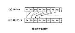
図9は、1/2に縮小表示させる場合の例である。図9(a)に示すように、1ピクセル毎に画像データP1,P2,P3……がデータ変換部23に供給されるとすると、データ変換部23では、図9(b)に示すように、隣接する2ピクセルのデータを平均化したデータとして、水平方向に1/2に縮小させる。例えば、ピクセルP1,P2のデータの平均値をとってピクセルPaとし、このピクセルPaのデータを出力させる。これを図9(b)に示すようにデータを間引いた形で、FIFOメモリ22に書き込む。垂直方向については、図示しないが、例えば縮小率に応じて水平ラインを間引くことで、同様に縮小することができる。 FIG. 9 shows an example in which the display is reduced to ½. As shown in FIG. 9A, if image data P1, P2, P3,... Are supplied to the
図10は、1/2に縮小表示させる場合の別の例である。図10(a)に示すように、1ピクセル毎に画像データP1,P2,P3……がデータ変換部23に供給されるとすると、データ変換部23では、図10(b)に示すように、隣接する3ピクセルのデータを平均化したデータとする。この場合、平均をとるピクセルは、2ピクセルずつシフトさせていき、一部のピクセルが重複して平均加算されるようにする。即ち図10に示すように、例えば縮小されて出力される最初のピクセルPa′は、原画像データのピクセルP1,P2,P3を加算して平均化したデータとし、次のピクセルPb′は、原画像データのピクセルP3,P4,P5を加算して平均化したデータとし、ピクセルP3のデータが隣接ピクセルで重複使用されるようにする。このようにしても、縮小表示が可能である。 FIG. 10 shows another example in the case of reducing the display to 1/2. As shown in FIG. 10 (a), if image data P1, P2, P3... Are supplied to the
なお、図8、図9、図10に示した拡大や縮小の処理は、FIFOメモリ22に画像データが入る前に、データ変換部23に供給して行うようにしたが、FIFOメモリ22から出力させる際に、同様の処理を行うようにして、直接拡大又は縮小させるようにしてもよい。 The enlargement / reduction processing shown in FIGS. 8, 9, and 10 is performed by supplying the data to the
また、ここまでの説明では、2枚の画像を横並びに表示させる場合の例について説明したが、3枚以上の画像を横並びに表示させる場合にも適用可能であることは勿論である。 In the above description, an example in which two images are displayed side by side has been described, but it is needless to say that the present invention can also be applied to a case in which three or more images are displayed side by side.
11、12…画像コンテンツ蓄積部、13…画像処理部、14…ビデオメモリ、14a…第1の画像データ、14b…第2の画像データ、15…表示処理部、16…表示手段、21…ビデオメモリ制御回路、21a…ビデオメモリ制御回路の制御データ、22,22a,22b…ラインメモリ(FIFOメモリ)、23…データ変換部 DESCRIPTION OF
Claims (12)
Translated fromJapanese前記画像メモリに記憶された第1の画像データと第2の画像データを1ラインずつ読み出し、上記バッファの同一ライン上の異なる位置に配置させる読み出し手段と、
前記読み出し手段によりバッファ上に書き込まれた画像データに基づいて、前記第1の画像データによる画像と前記第2の画像データによる画像とをバッファから読み出して1画面中に並べて表示させる表示処理手段とを備えた
画像表示装置。It has an image memory that stores multiple image data, and a buffer storage device that temporarily stores them,
Reading means for reading the first image data and the second image data stored in the image memory one line at a time, and arranging them at different positions on the same line of the buffer;
Display processing means for reading out the image based on the first image data and the image based on the second image data from the buffer based on the image data written on the buffer by the reading means and displaying them side by side in one screen; An image display device.
前記読み出し手段はバッファ記憶装置として1つのラインメモリを使用した読み出し手段であり、前記表示処理手段で並べて表示させる配置位置に対応して、前記1つのラインメモリに交互に前記第1の画像データと前記第2の画像データを配置して読み出させる
画像表示装置。The image display device according to claim 1,
The reading means is a reading means using one line memory as a buffer storage device, and the first image data and the first image data are alternately displayed in the one line memory corresponding to the arrangement position to be displayed side by side by the display processing means. An image display device that arranges and reads the second image data.
前記読み出し手段は、前記表示処理手段で表示用の描画をしない領域についてもバッファ上に配置して出力させる
画像表示装置。The image display device according to claim 2,
The image reading apparatus in which the reading unit arranges and outputs an area in the display processing unit that is not drawn for display.
前記読み出し手段は、前記第1の画像データと前記第2の画像データの描画される領域だけをバッファ上に続けて配置させる
画像表示装置。The image display device according to claim 2,
The image display device, wherein the reading unit continuously arranges only the area where the first image data and the second image data are drawn on a buffer.
前記読み出し手段は、前記第1の画像データと前記第2の画像データを
バッファ上に配置する際、どこからどこまでが第1の画像データで、どこからどこまでが第2の画像データなのかを記憶する手段を有する
画像表示装置。The image display device according to claim 4.
The reading means stores, when arranging the first image data and the second image data on a buffer, where from where to where is the first image data and where from where is the second image data. An image display apparatus.
前記読み出し手段は、バッファに格納された前記第1の画像データと前記第2の画像データを前記表示処理手段に送るとき、第1の画像データをどの位置から表示させるのか、また、第2の画像データをどの位置から表示させるのかを、前記表示処理手段に送る画像表示装置。The image display device according to claim 4 or 5,
When the reading means sends the first image data and the second image data stored in the buffer to the display processing means, from which position the first image data is displayed, An image display device for sending to the display processing means from which position the image data is displayed.
前記読み出し手段はバッファ記憶装置として第1のラインメモリと第2のラインメモリを使用した読み出し手段であり、前記第1のラインメモリに前記第1の画像データを配置し、前記第2のラインメモリに前記第2の画像データを配置し、両ラインメモリに配置された画像データをライン単位で交互に読み出して出力させる
画像表示装置。The image display device according to claim 1,
The reading means is a reading means using a first line memory and a second line memory as a buffer storage device, and the first image data is arranged in the first line memory, and the second line memory An image display device in which the second image data is arranged in a line, and the image data arranged in both line memories are alternately read and output in line units.
前記読み出し手段は、前記第1のラインメモリから読み出した第1の画像データをライン上に配置する位置、前記第2のラインメモリから読み出した第2の画像データをライン上に配置する位置を指示するデータを前記表示処理手段に送る
画像表示装置。The image display device according to claim 7,
The reading means indicates a position where the first image data read from the first line memory is arranged on the line, and a position where the second image data read from the second line memory is arranged on the line. An image display device for sending data to be sent to the display processing means.
前記読み出し手段が備えるラインメモリへの書き込みを行う際に、
毎クロック新しい画像データを読み出すのではなく、画像データの同じピクセルを少しずつ繰り返しながらラインメモリに書き込むことで、拡大表示を可能とした画像表示装置。The image display device according to claim 1,
When writing to the line memory provided in the reading means,
An image display device that enables enlarged display by writing the same pixels of image data to the line memory while repeating little by little instead of reading new image data every clock.
前記読み出し手段が画像データからデータを読み出してバッファ記憶装置に書き込むのに使用するクロック周波数と、前記表示処理手段がバッファ記憶装置からデータを読み出す際に使用するクロック周波数とを異なるものとし、前記読み出し手段が使用するクロック周波数を高くして表示に必要な画像のみを選択してバッファ記憶装置に書き込むことにより、縮小表示を可能とした
画像表示装置。The image display device according to claim 1,
The clock frequency used when the reading means reads data from image data and writes it to the buffer storage device and the clock frequency used when the display processing means reads data from the buffer storage device are different from each other. An image display device capable of reduced display by selecting only an image necessary for display by increasing the clock frequency used by the means and writing it in a buffer storage device.
バッファ記憶装置からデータを読み込むクロック周波数を下げることにより、拡大表示を可能とした
画像表示装置。The image display device according to claim 10.
An image display device that enables enlarged display by lowering the clock frequency for reading data from a buffer storage device.
前記バッファ記憶装置として、FIFOを用いた
画像表示装置。In the image display device according to any one of claims 1 to 11,
An image display device using a FIFO as the buffer storage device.
Priority Applications (1)
| Application Number | Priority Date | Filing Date | Title |
|---|---|---|---|
| JP2004149347AJP2005331674A (en) | 2004-05-19 | 2004-05-19 | Image display apparatus |
Applications Claiming Priority (1)
| Application Number | Priority Date | Filing Date | Title |
|---|---|---|---|
| JP2004149347AJP2005331674A (en) | 2004-05-19 | 2004-05-19 | Image display apparatus |
Publications (1)
| Publication Number | Publication Date |
|---|---|
| JP2005331674Atrue JP2005331674A (en) | 2005-12-02 |
Family
ID=35486386
Family Applications (1)
| Application Number | Title | Priority Date | Filing Date |
|---|---|---|---|
| JP2004149347APendingJP2005331674A (en) | 2004-05-19 | 2004-05-19 | Image display apparatus |
Country Status (1)
| Country | Link |
|---|---|
| JP (1) | JP2005331674A (en) |
Cited By (5)
| Publication number | Priority date | Publication date | Assignee | Title |
|---|---|---|---|---|
| JP2008009140A (en)* | 2006-06-29 | 2008-01-17 | Fujitsu Ltd | Image processing apparatus and image processing method |
| JP2010097071A (en)* | 2008-10-17 | 2010-04-30 | Casio Computer Co Ltd | Display and display method |
| JP2017227864A (en)* | 2016-06-17 | 2017-12-28 | キヤノン株式会社 | Display unit and display control method |
| JP2021021925A (en)* | 2019-07-24 | 2021-02-18 | 深▲せん▼市▲潁▼▲創▼科技有限公司Shenzhen Yingchuang Technology Co., Ltd. | Mirroring screen display method and mirroring screen rotation method |
| US11194993B2 (en) | 2016-06-17 | 2021-12-07 | Canon Kabushiki Kaisha | Display apparatus and display control method for displaying images |
Citations (5)
| Publication number | Priority date | Publication date | Assignee | Title |
|---|---|---|---|---|
| JPH07104723A (en)* | 1993-10-07 | 1995-04-21 | Toshiba Corp | Display system |
| JPH08211849A (en)* | 1995-02-02 | 1996-08-20 | Casio Comput Co Ltd | Display controller |
| JPH0981111A (en)* | 1995-09-14 | 1997-03-28 | Ricoh Co Ltd | Image display controller |
| JPH09325745A (en)* | 1996-06-07 | 1997-12-16 | Mega Chips:Kk | Picture processor |
| JP2003195852A (en)* | 2001-12-28 | 2003-07-09 | Canon Inc | Image processing device |
- 2004
- 2004-05-19JPJP2004149347Apatent/JP2005331674A/enactivePending
Patent Citations (5)
| Publication number | Priority date | Publication date | Assignee | Title |
|---|---|---|---|---|
| JPH07104723A (en)* | 1993-10-07 | 1995-04-21 | Toshiba Corp | Display system |
| JPH08211849A (en)* | 1995-02-02 | 1996-08-20 | Casio Comput Co Ltd | Display controller |
| JPH0981111A (en)* | 1995-09-14 | 1997-03-28 | Ricoh Co Ltd | Image display controller |
| JPH09325745A (en)* | 1996-06-07 | 1997-12-16 | Mega Chips:Kk | Picture processor |
| JP2003195852A (en)* | 2001-12-28 | 2003-07-09 | Canon Inc | Image processing device |
Cited By (5)
| Publication number | Priority date | Publication date | Assignee | Title |
|---|---|---|---|---|
| JP2008009140A (en)* | 2006-06-29 | 2008-01-17 | Fujitsu Ltd | Image processing apparatus and image processing method |
| JP2010097071A (en)* | 2008-10-17 | 2010-04-30 | Casio Computer Co Ltd | Display and display method |
| JP2017227864A (en)* | 2016-06-17 | 2017-12-28 | キヤノン株式会社 | Display unit and display control method |
| US11194993B2 (en) | 2016-06-17 | 2021-12-07 | Canon Kabushiki Kaisha | Display apparatus and display control method for displaying images |
| JP2021021925A (en)* | 2019-07-24 | 2021-02-18 | 深▲せん▼市▲潁▼▲創▼科技有限公司Shenzhen Yingchuang Technology Co., Ltd. | Mirroring screen display method and mirroring screen rotation method |
Similar Documents
| Publication | Publication Date | Title |
|---|---|---|
| JP2004522365A (en) | Apparatus and method for high-quality multi-screen division with multi-channel input | |
| US20120229599A1 (en) | Video signal processing device and video signal processing method | |
| KR980013377A (en) | Video signal converter and TV signal processor | |
| JPWO2009147795A1 (en) | Video processing system | |
| JP2003528549A (en) | Method and apparatus for recording and displaying two different video programs simultaneously | |
| TWI245560B (en) | Video data processing method and apparatus capable of saving bandwidth | |
| US8493512B2 (en) | Digital broadcast receiver apparatus and image display method | |
| JP2008311981A (en) | Image signal processing apparatus, image signal processing method, program, camera instrument, image display apparatus, and image signal output apparatus | |
| EP0979005B1 (en) | Image decoder | |
| JP2007259193A (en) | Video output apparatus and method | |
| JP2005331674A (en) | Image display apparatus | |
| KR101648449B1 (en) | Method of processing image in a display apparatus and the display apparatus | |
| KR100757735B1 (en) | A method of determining a horizontal line activation time for minimizing memory in a display device, a method of performing IP using the same, and a display device using the same. | |
| TWI316818B (en) | Method of scaling subpicture data and related apparatus thereof | |
| JP2000221952A (en) | Image display device | |
| JP4323776B2 (en) | Multi-channel video processing apparatus and method | |
| JP2002300492A (en) | Broadcast receiving device and program display method | |
| JP4960433B2 (en) | Image processing apparatus, receiving apparatus, and display apparatus | |
| JP2008306660A (en) | Video signal processing device | |
| JP4357239B2 (en) | Video signal processing device and video display device | |
| JP2737557B2 (en) | Dual screen television receiver and dual screen processing circuit | |
| JP2013247582A (en) | Video composition method, video recording method, video composition device, video recording device, and video display system | |
| JPH11177884A (en) | Multi-screen display device | |
| KR100662422B1 (en) | Data broadcasting scaling device and scaling method using the same | |
| EP1482477A2 (en) | Video signal processing apparatus for processing a plurality of video signals differing in format |
Legal Events
| Date | Code | Title | Description |
|---|---|---|---|
| A621 | Written request for application examination | Free format text:JAPANESE INTERMEDIATE CODE: A621 Effective date:20070507 | |
| A977 | Report on retrieval | Free format text:JAPANESE INTERMEDIATE CODE: A971007 Effective date:20100707 | |
| A131 | Notification of reasons for refusal | Free format text:JAPANESE INTERMEDIATE CODE: A131 Effective date:20100713 | |
| A02 | Decision of refusal | Free format text:JAPANESE INTERMEDIATE CODE: A02 Effective date:20101130 |