JP2005323740A - Syringe holder for balloon catheter, and syringe set for balloon catheter - Google Patents
Syringe holder for balloon catheter, and syringe set for balloon catheterDownload PDFInfo
- Publication number
- JP2005323740A JP2005323740AJP2004143616AJP2004143616AJP2005323740AJP 2005323740 AJP2005323740 AJP 2005323740AJP 2004143616 AJP2004143616 AJP 2004143616AJP 2004143616 AJP2004143616 AJP 2004143616AJP 2005323740 AJP2005323740 AJP 2005323740A
- Authority
- JP
- Japan
- Prior art keywords
- syringe
- cylinder
- syringes
- balloon catheter
- balloon
- Prior art date
- Legal status (The legal status is an assumption and is not a legal conclusion. Google has not performed a legal analysis and makes no representation as to the accuracy of the status listed.)
- Pending
Links
- 230000004308accommodationEffects0.000claimsdescription30
- 238000012423maintenanceMethods0.000claimsdescription2
- 238000003825pressingMethods0.000abstractdescription5
- 230000001954sterilising effectEffects0.000description26
- 238000004659sterilization and disinfectionMethods0.000description26
- 230000002093peripheral effectEffects0.000description11
- 238000000034methodMethods0.000description8
- 239000002872contrast mediaSubstances0.000description7
- 230000007423decreaseEffects0.000description5
- 238000003780insertionMethods0.000description5
- 230000037431insertionEffects0.000description5
- 239000007788liquidSubstances0.000description5
- IAYPIBMASNFSPL-UHFFFAOYSA-NEthylene oxideChemical compoundC1CO1IAYPIBMASNFSPL-UHFFFAOYSA-N0.000description3
- -1polypropylenePolymers0.000description3
- 230000001105regulatory effectEffects0.000description3
- 239000004698PolyethyleneSubstances0.000description1
- 239000004743PolypropyleneSubstances0.000description1
- 239000004793PolystyreneSubstances0.000description1
- 239000000853adhesiveSubstances0.000description1
- 230000001070adhesive effectEffects0.000description1
- MTAZNLWOLGHBHU-UHFFFAOYSA-Nbutadiene-styrene rubberChemical compoundC=CC=C.C=CC1=CC=CC=C1MTAZNLWOLGHBHU-UHFFFAOYSA-N0.000description1
- 238000011038discontinuous diafiltration by volume reductionMethods0.000description1
- 230000000694effectsEffects0.000description1
- 230000002349favourable effectEffects0.000description1
- 238000003384imaging methodMethods0.000description1
- 239000000463materialSubstances0.000description1
- 239000000113methacrylic resinSubstances0.000description1
- 229920006173natural rubber latexPolymers0.000description1
- 229920000515polycarbonatePolymers0.000description1
- 239000004417polycarbonateSubstances0.000description1
- 229920000573polyethylenePolymers0.000description1
- 229920000139polyethylene terephthalatePolymers0.000description1
- 239000005020polyethylene terephthalateSubstances0.000description1
- 229920001155polypropylenePolymers0.000description1
- 229920002223polystyrenePolymers0.000description1
- 238000004904shorteningMethods0.000description1
Images


Classifications
- A—HUMAN NECESSITIES
- A61—MEDICAL OR VETERINARY SCIENCE; HYGIENE
- A61M—DEVICES FOR INTRODUCING MEDIA INTO, OR ONTO, THE BODY; DEVICES FOR TRANSDUCING BODY MEDIA OR FOR TAKING MEDIA FROM THE BODY; DEVICES FOR PRODUCING OR ENDING SLEEP OR STUPOR
- A61M5/00—Devices for bringing media into the body in a subcutaneous, intra-vascular or intramuscular way; Accessories therefor, e.g. filling or cleaning devices, arm-rests
- A61M5/008—Racks for supporting syringes or needles
- A—HUMAN NECESSITIES
- A61—MEDICAL OR VETERINARY SCIENCE; HYGIENE
- A61M—DEVICES FOR INTRODUCING MEDIA INTO, OR ONTO, THE BODY; DEVICES FOR TRANSDUCING BODY MEDIA OR FOR TAKING MEDIA FROM THE BODY; DEVICES FOR PRODUCING OR ENDING SLEEP OR STUPOR
- A61M25/00—Catheters; Hollow probes
- A61M25/10—Balloon catheters
- A61M25/1002—Balloon catheters characterised by balloon shape
- A—HUMAN NECESSITIES
- A61—MEDICAL OR VETERINARY SCIENCE; HYGIENE
- A61M—DEVICES FOR INTRODUCING MEDIA INTO, OR ONTO, THE BODY; DEVICES FOR TRANSDUCING BODY MEDIA OR FOR TAKING MEDIA FROM THE BODY; DEVICES FOR PRODUCING OR ENDING SLEEP OR STUPOR
- A61M25/00—Catheters; Hollow probes
- A61M25/10—Balloon catheters
- A61M25/1018—Balloon inflating or inflation-control devices
- A61M25/10181—Means for forcing inflation fluid into the balloon
- A61M25/10182—Injector syringes
- A—HUMAN NECESSITIES
- A61—MEDICAL OR VETERINARY SCIENCE; HYGIENE
- A61M—DEVICES FOR INTRODUCING MEDIA INTO, OR ONTO, THE BODY; DEVICES FOR TRANSDUCING BODY MEDIA OR FOR TAKING MEDIA FROM THE BODY; DEVICES FOR PRODUCING OR ENDING SLEEP OR STUPOR
- A61M25/00—Catheters; Hollow probes
- A61M25/10—Balloon catheters
- A61M25/1018—Balloon inflating or inflation-control devices
- A61M25/10184—Means for controlling or monitoring inflation or deflation
- A61M25/10187—Indicators for the level of inflation or deflation
Landscapes
- Health & Medical Sciences (AREA)
- Life Sciences & Earth Sciences (AREA)
- Heart & Thoracic Surgery (AREA)
- Public Health (AREA)
- Animal Behavior & Ethology (AREA)
- Veterinary Medicine (AREA)
- Engineering & Computer Science (AREA)
- Anesthesiology (AREA)
- Biomedical Technology (AREA)
- Hematology (AREA)
- General Health & Medical Sciences (AREA)
- Biophysics (AREA)
- Child & Adolescent Psychology (AREA)
- Pulmonology (AREA)
- Vascular Medicine (AREA)
- Infusion, Injection, And Reservoir Apparatuses (AREA)
- Media Introduction/Drainage Providing Device (AREA)
Abstract
Description
Translated fromJapanese本発明は、バルーンカテーテルに使用されるシリンジを収容保持するシリンジホルダ及びシリンジホルダにシリンジを収容したシリンジセットに関する。 The present invention relates to a syringe holder that houses and holds a syringe used for a balloon catheter, and a syringe set that houses a syringe in the syringe holder.
生体に処置を行う処置具としては、バルーンカテーテルがあげられる。バルーンカテーテルは、体内に挿入されるカテーテルを有し、カテーテルの先端にはバルーンが取り付けられている。バルーンは、カテーテルの外周にチューブを被せ、その両端を固定することで形成されている。カテーテルには、バルーン内に連通するルーメンが形成されており、このルーメンに空気を送り込むことでバルーンを膨らませることができるようになっている(例えば、特許文献1参照)。 An example of a treatment tool that performs treatment on a living body is a balloon catheter. The balloon catheter has a catheter inserted into the body, and a balloon is attached to the distal end of the catheter. The balloon is formed by covering the outer periphery of the catheter with a tube and fixing both ends thereof. In the catheter, a lumen communicating with the inside of the balloon is formed, and the balloon can be inflated by sending air into the lumen (see, for example, Patent Document 1).
ところで、従来では、バルーンカテーテルを管腔内で使用する場合には、造影剤を注入してX線撮影をして、バルーンの径を確認しつつ空気の供給量を制御することが多かった。この場合には、バルーンの内、管腔内壁に押し当てられる部分では造影剤が押しのけられるので、バルーンの輪郭を明確に確認できるが、造影剤の影となる部分ではその輪郭がぼやけてしまうので、バルーンの正確な大きさを確認し難かった。 By the way, conventionally, when a balloon catheter is used in a lumen, it is often the case that a contrast medium is injected and X-ray imaging is performed to control the air supply amount while confirming the diameter of the balloon. In this case, the contrast agent is pushed away at the portion of the balloon that is pressed against the inner wall of the lumen, so that the contour of the balloon can be clearly confirmed, but the contour is blurred at the shadow portion of the contrast agent. It was difficult to check the exact size of the balloon.
そこで、X線で確認しなくてもバルーンの大きさを制御できるように、容量の異なるシリンジを予め複数容易し、所望の容積のシリンジをバルーンカテーテルに接続して使用することでバルーンの大きさを制御できるようにしたものがある。この場合には、複数のシリンジが予めバルーンカテーテルの滅菌パック内に用意されており、必要なシリンジを滅菌パックから取り出して使用する。また、複数のシリンジが1つの滅菌パックに収容され、この滅菌パックがバルーンカテーテルの滅菌パック内に収容されることもある。
しかしながら、滅菌パック内に複数のシリンジをそのまま収容する場合には、移送の途中などでシリンジが滅菌パック内でばらばらになってしまうことが多く、必要なシリンジを取り出し難かった。また、シリンジのみを収容する滅菌パックをさらに他の滅菌パックに収容する場合には、シリンジが2重に包装されているので、シリンジを取り出すまでに手間がかかった。さらに、手技の効率化という観点からは、外形が近似する複数のシリンジの中から手技に最適なシリンジを容易に選択できることが望ましい。
この発明は、このような事情に鑑みてなされたものであり、その目的とするところは、複数のシリンジを選択可能に有する場合であっても、その取扱性を良好にすることである。However, when a plurality of syringes are accommodated as they are in the sterilization pack, the syringes are often scattered in the sterilization pack during the transfer, and it is difficult to take out the necessary syringes. Moreover, when accommodating the sterilization pack which accommodates only a syringe in another sterilization pack, since the syringe was packaged twice, it took time and effort to take out the syringe. Furthermore, from the viewpoint of improving the efficiency of the procedure, it is desirable that a syringe most suitable for the procedure can be easily selected from a plurality of syringes having similar outer shapes.
This invention is made | formed in view of such a situation, The place made into the objective is to make the handling property favorable even when it is a case where it has a several syringe so that selection is possible.
上記の課題を解決する本発明の請求項1に係る発明は、バルーンカテーテルに接続されるシリンジを着脱自在に収容する収容溝が複数設けられたことを特徴とするバルーンカテーテル用のシリンジホルダとした。
このシリンジホルダは、複数の収容溝が設けられており、その各々にシリンジを収容することができるので、複数のシリンジを一つのユニットとして取り扱うことができるようになる。収容溝は、シリンジを着脱自在に構成されているので、使用時には、必要なシリンジのみを取り出すことができる。The invention according to claim 1 of the present invention for solving the above-mentioned problems is a syringe holder for a balloon catheter, characterized in that a plurality of receiving grooves are provided for detachably receiving syringes connected to the balloon catheter. .
Since this syringe holder is provided with a plurality of receiving grooves, each of which can accommodate a syringe, the plurality of syringes can be handled as one unit. Since the accommodation groove is configured so that the syringe is detachable, only the necessary syringe can be taken out during use.
請求項2に係る発明は、請求項1に記載のバルーンカテーテル用のシリンジホルダにおいて、前記保持部は、前記シリンジの外形に対して遊びをもって形成された前記収容溝と、前記収容溝の内面に設けられた少なくとも1つの突出部とを有することを特徴とする。
このシリンジホルダでは、シリンジを収容溝に収容させると、シリンジと収容溝との間に隙間を形成させることができる。さらに、主に突出部でシリンジが支持されることになるので、シリンジと収容溝との接触面積が減少する。The invention according to
In this syringe holder, when the syringe is accommodated in the accommodation groove, a gap can be formed between the syringe and the accommodation groove. Furthermore, since the syringe is mainly supported by the protruding portion, the contact area between the syringe and the accommodation groove is reduced.
請求項3に係る発明は、請求項1又は請求項2に記載のバルーンカテーテル用のシリンジホルダにおいて、前記収容溝は、その長さ方向に略直交する断面が非円形であることを特徴とする。
このシリンジホルダでは、収容溝が断面視で非円形になっているので、シリンジとの間に隙間が生じやすい。The invention according to
In this syringe holder, since the accommodation groove is non-circular in sectional view, a gap is likely to be formed between the syringe holder and the syringe holder.
請求項4に係る発明は、請求項1から請求項3のいずれか一項に記載のバルーンカテーテル用のシリンジホルダにおいて、外径の異なる複数の前記シリンジに対応できるように、大きさの異なる前記収容溝が配列されていることを特徴とする。
このシリンジホルダでは、大きさの異なる収容溝を配列させてあるので、シリンジの大きさが異なる場合であっても収容することができる。シリンジの大きさに応じてバルーンに送り込む空気の量を変化させる場合に、そのような複数のシリンジの取り扱いが容易になる。さらに、容積の異なるシリンジが複数配置されていた場合には、シリンジの大きさによって直感的に必要なシリンジを選択できるようになる。According to a fourth aspect of the present invention, in the syringe holder for a balloon catheter according to any one of the first to third aspects, the sizes are different so as to correspond to the plurality of syringes having different outer diameters. The receiving grooves are arranged.
In this syringe holder, since the accommodation grooves having different sizes are arranged, the syringe holders can be accommodated even when the sizes of the syringes are different. When changing the amount of air fed into the balloon according to the size of the syringe, handling of such a plurality of syringes becomes easy. Furthermore, when a plurality of syringes having different volumes are arranged, a necessary syringe can be selected intuitively depending on the size of the syringe.
請求項5に係る発明は、請求項1から請求項4のいずれか一項に記載のバルーンカテーテル用のシリンジホルダにおいて、前記収容溝には、前記シリンジのつばに当接することで前記シリンジの回転を規制する平面部が設けられていることを特徴とする。
このシリンジホルダでは、平面部によってシリンジの回転を規制することができるので、シリンジの回転方向の向き一定に保つことできる。例えば、シリンジ自体に何らかの情報が付されている場合などには、その情報の値を一定の方向に向けるように収容することができるので、シリンジの取り扱いが容易になる。According to a fifth aspect of the present invention, in the syringe holder for a balloon catheter according to any one of the first to fourth aspects, the rotation of the syringe is brought into contact with the collar of the syringe in the accommodation groove. It is characterized in that a flat surface part for regulating is provided.
In this syringe holder, since the rotation of the syringe can be regulated by the flat portion, the direction of the rotation direction of the syringe can be kept constant. For example, when some information is attached to the syringe itself, the value of the information can be accommodated so as to be directed in a certain direction, so that the syringe can be easily handled.
請求項6に係る発明は、請求項1から請求項5のいずれか一項に記載のバルーンカテーテル用のシリンジホルダにおいて、前記収容溝には、前記シリンジが前記バルーンカテーテルに接続される接続部側先端部を突出させる開口部が形成されていることを特徴とする。
このシリンジホルダでは、シリンジの先端部がシリンジホルダから突出するように収容されるので、この突出した部分を掴めば、シリンジを簡単に取り外せる。The invention according to
In this syringe holder, since the front-end | tip part of a syringe is accommodated so that it may protrude from a syringe holder, if this protruding part is grasped, a syringe can be removed easily.
請求項7に係る発明は、請求項1から請求項6のいずれか一項に記載のバルーンカテーテル用のシリンジホルダと、前記保持部に収容された複数の前記シリンジとを有することを特徴とするバルーンカテーテル用のシリンジセットとした。
このシリンジセットでは、複数のシリンジが一体的に取り扱われるようになる。特定のシリンジをしようする際には、該当するシリンジをシリンジホルダから取り出して、バルーンカテーテルに接続する。The invention which concerns on
In this syringe set, a plurality of syringes are handled integrally. When using a specific syringe, the corresponding syringe is removed from the syringe holder and connected to the balloon catheter.
本発明によれば、シリンジホルダに複数のシリンジを収容させることで、滅菌パック内でシリンジがばらばらになることがなく、一体的に取り扱うことが可能になるので、使用時の取り扱い、もしくは選択が容易になる。したがって、手技を容易にし、手技時間の短縮化が図れる。
また、シリンジホルダの収容溝に遊びを設けることで、シリンジとの間に隙間を形成させたので、エチレンオキサイドガス等を用いたガス滅菌がしやすくなる。さらに、突出部でシリンジとシリンジホルダとの接触面積を少なくすると、さらに確実にシリンジとシリンジホルダとの間の隙間を滅菌できるようになる。According to the present invention, since a plurality of syringes are accommodated in the syringe holder, the syringes can be handled integrally without being separated in the sterilization pack. It becomes easy. Therefore, the procedure can be facilitated and the procedure time can be shortened.
Moreover, since a clearance is formed between the syringe holder and the accommodation groove of the syringe holder, gas sterilization using ethylene oxide gas or the like is facilitated. Furthermore, if the contact area between the syringe and the syringe holder is reduced at the protruding portion, the gap between the syringe and the syringe holder can be sterilized more reliably.
発明を実施するための最良の形態について図面を参照しながら詳細に説明する。
図1及び図2に示すように、シリンジセット1には、3つのシリンジ2,3,4がシリンジホルダ5に収容保持されている。
図3に示すようにシリンジ2は、外筒部であるシリンダ6と、シリンダ6内に摺動自在に挿入されるプランジャ(押し子)7とを有している。
シリンダ6の先端には、縮径された先端部6aが設けられ、先端部6aからは接続部8が軸線に沿って延設されている。接続部8は、その中心線上にシリンダ6内と外部とを連通させる流出口9が形成されている。この流出口9は、後述するバルーンカテーテルに空気を導くために形成されている。さらに、接続部8には、流出口9を覆うように円筒部10が設けられており、円筒部10には内ネジ10aが刻まれている。シリンダ6の基端部6bには、挿入口11aがプランジャ7を挿入可能に設けられている。また、シリンダ6の基端部6bには、つば12aがシリンダ6の軸線と略直交する方向で、かつシリンダ6の一直径方向に延設されている。シリンダ6は、縮径された先端部6aを除いて基端部6bの挿入口11aに至るまで、略等しい内径を有している。なお、挿入口11aの近傍の内周面には、プランジャ7の抜け落ちを防止するための突起(不図示)が設けられている。The best mode for carrying out the invention will be described in detail with reference to the drawings.
As shown in FIGS. 1 and 2, three
As shown in FIG. 3, the
At the tip of the
ここで、シリンダ6の外周面には、軸線方向に沿って目盛13aが設けられている。目盛13aは、シリンダ内に形成される空間の容積を先端部6a側を基準として計測した結果を示すものでも良いし、目盛の位置から先端まで、後述するシール部材19aを移動させたときに、膨らむバルーンの外径を示すものでも良い。
シリンダ6には、目盛13aに重なるように、孔14が設けられている。孔14は、シリンダ6の内部と外部とを連通させるもので、シリンダ6内部が予め設定された容積(第1の容積)になる位置に形成されている。この第1の容積は、例えば、バルーンを直径8.5mmの大きさで拡張させるだけの空気量に相当する。
さらに、シリンダ6には、孔14から周方向に約1/4周(角度にして略90度)だけずれた位置に、孔15が形成されている。孔15は、シリンダ6の内部と外部とを連通させるもので、孔15と略同じ大きさに形成されている。Here, a
A
Further, a
プランジャ7は、板片17aを十文字状に交差させた本体部18aを有している。本体部18aは、シリンダ6内に挿入可能な大きさを有し、本体部6の先端には、シール部材19aが取り付けられている。シール部材19aは、シリンダ6の内周面に摺接するシール面20aを有し、シリンダ6の内周面とシール部材19aとの間では気密が保たれるようになっている。さらに、本体部18aの基端には、円板状の押圧部21が取り付けられている。 The
シリンジ3は、シリンジ2よりも内径及び外径が大きいシリンダ22と、このシリンダ22内に摺動自在に挿入されるプランジャ23とを有し、シリンジ2と同様の構成になっている。すなわち、シリンダ22には、先端部22aに接続部8が設けられ、基端部22bには挿入口11bが形成されている。また、基端部22bにはつば12bが延設されている。このシリンダ22には、先端部22aを基準として、例えば、バルーンを直径11.5mmの大きさで拡張させるだけの空気量(第2の容積)に相当する位置に、2つの孔24,25が設けられている。孔24は、目盛13b上に設けられ、孔25は、孔24から周方向に約90度ずれた位置に設けられている。なお、プランジャ23は、シリンダ22に対応した大きさを有し、板片17bを交差させた本体部18bの先端にはシール部材19bが取り付けられている。シール部材19bの外周面は、シリンダ22の内周面に気密を保持するように摺接するシール面20bになっている。 The
シリンジ4は、シリンジ3よりも内径及び外径が大きいシリンダ26と、このシリンダ26内に摺動自在に挿入されるプランジャ27とを有し、シリンジ2,3と同様の構成になっている。すなわち、シリンダ26には、先端部26aに接続部8が設けられ、基端部26bには挿入口11cが形成されている。また、基端部26bにはつば12cが設けられている。このシリンダ26には、先端部26aを基準として、例えば、バルーンを直径15mmの大きさで拡張させるだけの空気量(第3の容積)に相当する位置に、2つの孔28,29が設けられている。孔28は、目盛13c上に設けられ、孔29は、孔28から周方向に約90度ずれた位置に設けられている。なお、プランジャ27は、シリンダ26に対応した大きさを有し、板片17cを交差させた本体部18cの先端にはシール部材19cが取り付けられている。シール部材19cの外周面は、シリンダ27の内周面に気密を保持するように摺接するシール面20cになっている。 The
図1及び図2に示すように、シリンジホルダ5は、平面視で略長方形のシートの周縁部をつば30とし、その内側を上側に膨出させて本体部31を形成している。本体部31は、側面視においてつば30を底面とする台形になっている。この本体部31の短辺は、シリンジ2,3,4の長さよりも短い。さらに、本体部31には、本体部31の長辺に沿って3つの保持部32,33,34が平行に凹設されている。
保持部32は、上面側が開口された収容溝を有し、収容溝は、側面31a側からシリンダ収容溝35a、つば収容溝36a、プランジャ収容溝37aに区画されている。これら溝35a,36a,37aは連通し、本体部31の側面31aに開口部32aが形成され、本体部31の対向する側面31b側は閉塞されている。As shown in FIGS. 1 and 2, the
The holding
図2に示すように、シリンダ収容溝35aは、シリンダ6の径よりも大きい幅及び深さを有している。さらに、シリンダ収容溝35aの上部開口32bの縁部は、上部開口32bの幅を減じるように膨出している。
図1に示すように、つば収容溝36aは、シリンダ収容溝35aに連なり、その幅はシリンダ収容溝35aよりも大きい。図4に示すように、つば収容溝36aの側壁は、底部に向かって幅を減じるような勾配を有し、底部は、なだらかな凹形になっている。図5に示すように、つば収容溝36aの深さは、シリンダ収容溝35aよりも大きく、つば収容溝36aとシリンダ収容溝35aとの境界面は勾配をもつように形成されている。同様に、つば収容溝36aと、プランジャ収容溝37aとの境界面は、勾配をもつように形成されている。
プランジャ収容溝37aの深さは、つば収容溝36aの深さと同程度であり、底部は、プランジャ7の押圧部21よりも曲率が小さくなっている。図4に示すように、プランジャ収容溝37aの幅は、つば収容溝36aの幅よりも狭くなっている。プランジャ収容溝37aの他端側は、閉塞面38aにより閉塞されており、この閉塞面38aはプランジャ収容溝37aの長さを底部に向かって減じるような勾配が付けられている。As shown in FIG. 2, the
As shown in FIG. 1, the
The depth of the
図1及び図4に示すように、保持部33の収容溝は、シリンダ収容溝35b、つば収容溝36b、プランジャ収容溝37bに区画され、側面31a側に開口部33aが形成されている。シリンダ収容溝35bの幅及び深さは、シリンダ収容溝35aよりも大きくなっている。つば収容溝36bの幅及び深さは、シリンダ収容溝35bよりも大きく、その底部は凹形になっている。プランジャ収容溝37bの深さは、つば収容溝36bと同程度で、その幅はつば収容溝36bよりも狭い。なお、プランジャ収容溝37bの他端側の閉塞面38b、プランジャ収容溝37bとつば収容溝36bの境界面、つば収容溝36bとシリンダ収容溝35bの境界面は、それぞれ保持部32において対応する面と同様の勾配が付けられている。 As shown in FIGS. 1 and 4, the holding groove of the holding
保持部34は、保持部33と幅及び深さが異なる他は同様の構成になっている。すなわち、側面31a側に開口部34aを有し、シリンダ収容溝35c、つば収容溝36c、プランジャ収容溝37cに区画されている。つば収容溝36cの幅及び深さは、シリンダ収容溝35cよりも大きく、その底部は凹形になっている。プランジャ収容溝37cの深さは、つば収容溝36cと同程度で、その幅はつば収容溝36cよりも狭い。プランジャ収容溝37cの他端側の閉塞面38c、プランジャ収容溝35cとつば収容溝36cの境界面、つば収容溝36cとシリンダ収容溝35cの境界面は、それぞれ収容部32,33において対応する面と同様の勾配が付けられている。
なお、このようなシリンジホルダ5は、可撓性を有する素材、例えば、ポリプロピレン又はポリエチレン、ポリスチレン又はポリエチレンテレフタレート、ポリカーボネート又はABS(アセト二トリルブタジエンスチレン)、メタクリル樹脂などのシートを真空(圧空)成形することにより製造されている。The holding
The
ここで、シリンジセット1と共に滅菌パックに収容されるバルーンカテーテルの一例について図6及び図7を参照して説明する。
図6に示すバルーンカテーテル40は、管腔内に挿入される可撓性のカテーテル(シース)41を有し、カテーテル41の先端部には、バルーン42が取り付けられている。バルーン42は、例えば、天然ゴムラテックスから製造されたチューブで、チューブ内にカテーテル41の先端部を貫通させた後に、その両端部42aを糸43で縛り付けると共に、接着剤を塗布するなどして固定されている。バルーン42に空気を供給すると、図7に示すように、固定されていない中間部42bを膨らませることができる。
カテーテル41内には、膨張ルーメン44が形成されている。膨張ルーメン44は、その先端部分が閉塞されると共に、バルーン42の中間部42bに連通する側孔45が形成されている。また、カテーテル41内には、ガイドルーメン46と送液ルーメン47とが略平行に形成されている。ガイドルーメン46には、カテーテル41の先端部を管腔内に案内する際に、ガイドワイヤや、スタイレットを挿通される。送液ルーメン47は、管腔に造影剤を注入するために用いられる。送液ルーメン47の先端部は、閉塞されると共に、外部に連通する側孔48が設けられている。なお、送液ルーメン47を形成せずに、ガイドルーメン46を用いて造影剤を注入するようにしても良い。Here, an example of the balloon catheter accommodated in the sterilization pack together with the syringe set 1 will be described with reference to FIGS. 6 and 7.
A
An
図6に示すように、カテーテル41の基端部には、操作部49が設けられている。操作部49は、カテーテル41に接続される分岐部50を有し、分岐部50からは、膨張シャフト51とガイドシャフト52とが延設されている。膨張シャフト51内には、膨張ルーメン44に連通するルーメンが設けられており、膨張シャフト51の基端部にはルアー形状の口金53が取り付けられている。この口金53には、弁54を介してシリンジ2,3,4のいずれか1つが接続されるようになっている。また。ガイドシャフト52の基端部には、口金55が取り付けられている。この口金55には、2つの入口56,57が設けられている。入口56は、ガイドルーメン46に連通しており、ここからガイドワイヤを挿入して、カテーテル41の剛性を高めて押し込み性能を向上させられるようになっている。また、入口57は、送液ルーメンに連通しており、ここには造影剤が収容された造影剤用シリンジを接続できるようになっている。 As shown in FIG. 6, an
次に、シリンジセット1及びシリンジホルダ5の作用について説明する。
まず、シリンジホルダ5の保持部32に、シリンジ2を収容する。具体的には、つば収容溝36aにシリンダ6のつば12aが収容されるように、シリンジホルダ5の上部開口32b側からシリンジ2を押し込む。シリンダ6は、シリンダ収容溝35aの上部開口32bの縁部を押し広げるように挿入される。このとき、シリンダ収容溝35aの長さは、シリンダ6よりも短いので、シリンダ6の先端部6a側は、シリンジホルダ5の側面31aから突出する。また、シリンダ6のつば12aは、つば収容溝36a内に収容され、押圧部21はプランジャ収容溝37aに収容される。Next, the operation of the syringe set 1 and the
First, the
ここで、シリンダ収容溝35aの幅及び深さは、シリンジ2よりも大きく、シリンジ2との間に遊びが形成されるようになっているので、滅菌処理時のオトークレーブによる高圧蒸気やエチレンオキサイドガスが浸透しやすくなっている。なお、シリンジ2のつば12aと、つば収容溝36a及びシリンダ収容溝35aの境界面とが当接するので、シリンジ2が開口部32a側から抜け落ちることはない。また、プランジャ収容溝37a側は、閉塞面38aで閉塞されているので、こちら側からシリンジ2が抜け落ちることはない。
同様に、保持部33にはシリンジ3を上部開口33bから挿入して保持させ、保持部34にはシリンジ4を上部開口34bから挿入して保持させる。Here, the width and depth of the
Similarly, the holding
シリンジホルダ5に各シリンジ2,3,4を収容させたシリンジセット1は、滅菌パック(不図示)に収容される。この滅菌パックには、この他に図6に示すバルーンカテーテル40などが収容された後に封がなされ、滅菌処理が施される。滅菌処理としては、例えば、オートクレーブによる高圧蒸気滅菌や、エチレンオキサイドガスによる滅菌があげられる。 The syringe set 1 in which the
バルーンカテーテル40を管腔内に挿入し、バルーン42を膨張させるときには、3つのシリンジ2,3,4の内から選択した1つのシリンジ2,3,4の接続部8の内ネジ10aを弁54に螺入し、両者を接続する。シリンジ2,3,4をシリンジホルダ5から取り外すときには、シリンジホルダ5から露出しているシリンジ2,3,4の先端部を掴んで引き出す。例えば、シリンジ2をバルーンカテーテル40に接続するときには、予めプランジャ7をシリンジ2の基端部2b側まで引き戻しておく。
シリンジ2を接続したら、一方の手でシリンダ6のつば12aと、プランジャ7の押圧部21とを指で挟み込むようにして保持し、他方の手でシリンダ6をもって、プランジャ7をシリンダ6の先端部6aに向かってゆっくりと押し込む。When the
When the
プランジャ7のシール部材19aのシール面20aが孔14,16に達するまでは、バルーン42(図3参照)には空気が供給されない。すなわち、プランジャ7が押し込まれると、シール部材19aとシリンダ6内とで形成される空間の容積は減少するが、容積の減少分に相当する空気は、抵抗の少ない2つの孔14,15から抜け出るので、バルーン42に空気は供給されない。
プランジャをさらに押し込んで、シール部材19aが孔14,15の形成位置を越えて先端部6a側に移動すると、バルーン42に空気が供給されるようになる。すなわち、シール部材19aが孔14,15よりも先端部6a側にあるので、シリンダ6の空間内の空気は孔14,15から抜け出さなくなり、容積の減少量に相当する空気が流出口9からバルーンカテーテル40に送り込まれる。この空気は、図6に示す膨張ルーメン44を通ってバルーン42に供給される。その結果、シリンダ6内の容積の減少量に応じてバルーン42が膨張する(図7参照)。
つまり、このシリンジ2では、プランジャ7を先端部6aまで押し込んだときには、第1の容積に相当する空気量が送りこまれ、これに応じた大きさでバルーン42が膨張させられる。シリンジ3を選択した場合であれば、第2の容積に相当する空気量が送りこれ、バルーン42が膨張させられる。シリンジ4を選択した場合であれば、第3の容積の相当する空気量が送り込まれ、バルーン42が膨張させられる。Air is not supplied to the balloon 42 (see FIG. 3) until the
When the plunger is further pushed in and the
That is, in this
ここで、プランジャ7,23,27を押し込むに際し、シリンダ6,22,26の外周面に指を沿えることがあるが、この場合に孔14,24,28又は孔15,25,29の一方を指で塞いでしまうことがある。しかしながら、この実施の形態では、孔が2つずつ設けられているので、2つの孔14,15,24,25,28,29が同時に指で塞がれることがなくなり、バルーン42に供給される空気量を確実に制御することができる。特に、2つの孔14,15,24,25,28,29が周方向に約90度ずれた位置に形成されているので、シリンダ6,22,26を挟むように指を添えた場合に、一方の孔14,24,28が塞がれたとしても、他方の孔15,25,29が塞がれることはない。 Here, when the
この実施の形態では、バルーン42を膨張させる大きさに応じて複数のシリンジ2,3,4を用意し、かつそれらシリンジ2,3,4をシリンジホルダ5に整列させて収容するようにしたので、滅菌パックへの収容している間や、滅菌パックから取り出して使用する際に、シリンジ2,3,4がバラバラになることが防止され、使いやすくなる。また、従来のように2重にした滅菌パック内に収容されることがなくなるので、必要なシリンジ2,3,4をすばやく取り出すことが可能になり、手技時間を短縮させることができる。
また、シリンジホルダ5からシリンジ2,3,4の先端部が突出しているので、シリンジホルダ5からシリンジ2,3,4を容易に取り出すことができる。In this embodiment, a plurality of
Further, since the tip portions of the
なお、シリンジ2,3,4は、孔14,15,24,25,28,29を有しなくても良い。プランジャ7,23,27を引き戻したときのシリンダ6,22,26内の容積がシリンジ2,3,4ごとに異なるので、孔を設けなくてもシリンジ2,3,4ごとに異なる大きさでバルーン42を拡張させることができるからである。 The
次に、本発明の第2の実施の形態について図面を参照して説明する。なお、第1の実施の形態と同じ構成要素には同一の符号を付してある。また、第1の実施の形態と重複する説明は省略する。
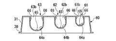
図8に示すように、シリンジホルダ60は、長辺に沿って3つの保持部61,62,63が凹設されている。
各保持部61,62,63は、本体部31の側面31aに開口部61a,62a,63aが設けられ、ここから側面31bに向かって延びている。このような保持部61,62,63は、シリンダ収容溝64a,64b,64cの形態が第1の実施の形態と異なる。Next, a second embodiment of the present invention will be described with reference to the drawings. In addition, the same code | symbol is attached | subjected to the same component as 1st Embodiment. Moreover, the description which overlaps with 1st Embodiment is abbreviate | omitted.
As shown in FIG. 8, the
Each holding
図8及び図9に示すように、シリンダ収容溝64aは、略U字形を有し、その幅及び深さはシリンダ6の径よりも大きく形成されている。シリンダ収容溝64aの底部には、突出部65が所定の間隔で3つ突設されている。この突出部65は、シリンダ6に点接触する形状及び大きさであり、その高さは、シリンダ6を突出部65に載せた状態でシリンダ6の上面がシリンダ収容溝64aの上部開口61bから突出しない程度の高さになっている。
さらに、図9に示すように、シリンダ収容溝64aの上部開口61b近傍の側壁のそれぞれには、突出部66がシリンダ収容溝64aの幅を減じるように対向して突設されている。突出部66の形成位置は、シリンダ6を突出部65上に載せた状態で、シリンダ6の上面との間に所定の隙間が形成される位置になっている。突出部66は、シリンダ収容溝64aの側壁に連なる基端部から先端部にかけて幅が減少させられており、先端部は上下方向に平行な平面になっている。図10に示すように、突出部66の基端部から先端部に至るまでの側面であって、シリンダ収容溝64aの底部側に臨む下側面66aは、上側面66bよりもなだらかになっている。また、突出部66は、本体部31の短辺方向の中心付近に対向配置されており、その各々がシリンダ収容溝64aの長さ方向に延びている。As shown in FIGS. 8 and 9, the
Furthermore, as shown in FIG. 9, a
図8及び図9に示すように、保持部62のシリンダ収容溝64bは、幅及び深さがシリンダ収容溝64aよりも大きくなっており、その底部には、突出部65が3つ設けられている。保持部62の上部開口62b近傍であって、シリンダ収容溝64bの側壁には、突出部66がシリンダ収容溝64bの長さ方向に沿って2つずつ対向配置されている。
保持部63のシリンダ収容溝64cは、幅及び深さがシリンダ収容溝64bよりも大きくなっており、その底部には、突出部65が3つ設けられている。保持部63の上部開口63bの近傍であって、シリンダ収容溝64cの側壁には、突出部66がシリンダ収容溝64cの長さ方向に沿って2つずつ対向配置されている。As shown in FIGS. 8 and 9, the
The
このシリンジセットの作用について説明する。
まず、シリンジホルダ60の保持部61に、シリンジ2を収容する。つば収容溝36aにシリンダ6のつば12aが収容されるように、上部開口61b側からシリンジ2を保持部61に押し込むと、シリンダ6が突出部66間を押し広げるようにして挿入され、シリンダ収容溝64a内に収まる。シリンダ6が通過した後には、突出部66が元の位置に戻る。
自然状態では、シリンジ2は、主にシリンダ収容溝64aの底部の突出部65に支持される。ここで、シリンダ収容溝64aは、シリンジ2よりも大きく、遊びを有している。
同様に、保持部62には、シリンジ3が収容され、保持部63にはシリンジ4が収容される。自然状態で各シリンジ3,4は、それぞれのシリンダ収容溝64b,64cの突出部65に主に支持される。The operation of this syringe set will be described.
First, the
In the natural state, the
Similarly, the
シリンジ2,3,4を収容したシリンジホルダ60は、滅菌パックに収容され、バルーンカテーテル40などと共に滅菌処理される。このとき、各シリンジ2,3,4と、保持部61,62,63との間には、十分な遊びがあり、シリンジ2,3,4と保持部61,62,63との接触面積は、突出部65,66などによって最小限の大きさになっているので、ガスが行き渡りやすくなっている。さらに、つば収容溝36a,36b,36c、及びプランジャ収容溝37a,37b,37cは、勾配を有する面や、シリンジ2,3,4とは異なる曲率を有する面から形成されており、シリンジ2,3、4との間に隙間が形成されているので、ガスが行き渡りやすくなっている。このため、滅菌ガスによって、シリンジ2,3,4が確実に滅菌される。 The
この実施の形態では、シリンジ2,3,4との間に十分な遊びが形成されるように保持部61,62,63を形成したので、保持部61,62,63とシリンジ2,3,4との間に隙間が確保され、シリンジ2,3,4の滅菌を確実に行うことができる。特に、突出部65,66などによってシリンジ2,3,4との接触面積が小さくなるようにしたので、シリンジ2,3,4の滅菌をさらに確実に行うことができる。
また、シリンジ2,3,4との間に遊びが形成されており、さらに各シリンジ2,3,4の先端部を露出させているので、シリンジ2,3,4の取り出しが容易になる。In this embodiment, since the holding
Moreover, since play is formed between the
次に、本発明の第3の実施の形態について図面を参照して説明する。なお、前記各実施の形態と同じ構成要素には同一の符号を付してある。また、前記各実施の形態と重複する説明は省略する。
この実施の形態は、保持部の他の形態に関するものである。
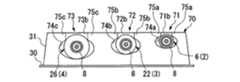
図11に示すように、シリンジホルダ70の保持部71,72,73は、シリンダ収容溝74a,74b,74cの断面形状が略楕円形になっている。
シリンダ収容溝74aは、上部開口71bの近傍が互いに近接するように膨出し、突出部75が形成され、底部側が楕円形になっている。シリンダ収容溝74aの内壁と、シリンダ6との接触部分は、底部側に1箇所、突出部75a側に2箇所の最大3箇所で、それぞれが線接触になっている。シリンジ2のその他の部分は、保持部71に接触せずに、隙間が形成されるようになっている。
保持部72のシリンダ収容溝74bは、シリンダ収容溝74aよりも大きく、上部開口72bの近傍に突出部75bを有し、底部側が楕円形状になっている。保持部73のシリンダ収容溝74cは、シリンダ収容溝74bよりも大きく、上部開口73bの近傍に突出部75cを有し、底部側が楕円形状になっている。Next, a third embodiment of the present invention will be described with reference to the drawings. In addition, the same code | symbol is attached | subjected to the same component as each said embodiment. Further, the description overlapping with each of the embodiments is omitted.
This embodiment relates to another form of the holding portion.
As shown in FIG. 11, in the holding
The
The
また、図12に示すようなシリンダ収容溝81,82,83であっても良い。
シリンダ収容溝81は、上部開口81bを基準とする略十字形になっている。シリンダ収容溝81の中央部分にシリンダ6が主に収容され、この中央部分から4方に延設される延設部81aによってシリンダ6との間に隙間が形成されている。延設部81aの基端にあたる各角部81bがシリンダ6と最大4箇所で線接触する。
シリンダ収容溝82は、上部開口82bを基準とする略T字形になっている。上部開口82bの幅は、シリンダ22よりも狭くなっている。底部側は、拡幅されており、この拡幅部82aによってシリンダ22との間に隙間が形成されている。このシリンダ収容溝82は、拡幅部82aの角部と、底部との最大3箇所でシリンダ22に線接触するようになっている。
シリンダ収容溝83は、略三角形を有している。この場合は、底部が三角形の底辺に相当し、上部開口83bが1つの頂点に相当する。上部開口83bの幅は、シリンダ26の外径よりも小さく、底部近傍の幅はシリンダ26より大きくなっている。このシリンダ収容溝83は、シリンダ26との間に隙間が形成され、底部と、傾斜する2つ側壁との最大3箇所でシリンダ26に接触するようになっている。
なお、このシリンジホルダは、いずれか一種類のシリンダ収容溝81,82,83を3つ配列させたものでも良い。Alternatively,
The
The
The
In addition, this syringe holder may be one in which any one type of
これらのシリンダ収容溝74a,74b,74c,81,82,83では、複数のシリンジ2,3,4を整列して保持させることができるので、使いやすくなり、手技時間の短縮化が図れる。また、シリンジ2,3,6とシリンダ溝74a,74b,74c,81,82,83との間に隙間が形成されているのでガス滅菌の際にガスが行き渡り易くなり、滅菌を十分に行えるようになる。 In these
次に、本発明の第4の実施の形態について図面を参照して説明する。なお、前記各実施の形態と同じ構成要素には同一の符号を付してある。また、前記各実施の形態と重複する説明は省略する。
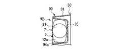
図13には、シリンジホルダ90に凹設された複数の保持部91の1つにシリンジ92が収容された状態が図示されている。
シリンジ92は、シリンダ26を有し、シリンダ26の外周面には表示部93がつば12cの延設方向からシリンダ26の周方向に約90度ずらした位置に設けられている。図13において、表示部93には、「For 15mm Balloon」、あるいは「15mm」との表示がなされている。これは、このシリンジ92は、バルーン42を最大で15mmの膨張径に相当する大きさで膨らませられることを意味している。Next, a fourth embodiment of the present invention will be described with reference to the drawings. In addition, the same code | symbol is attached | subjected to the same component as each said embodiment. Further, the description overlapping with each of the embodiments is omitted.
FIG. 13 illustrates a state in which the
The
シリンジホルダ90の保持部91は、つば収容溝94cが第2の実施の形態の保持部61と異なる。図14に示すように、つば収容溝94cは、その底部としての平面部95を有している。平面部95は、つば収容溝94cにシリンジ92を収容したときに、つば12cが平面部95とは密着しないが、平面部95がつば12cの回転を防止するような深さに設けられている。この平面部95によれば、他の方向の移動、例えば、つば12cの延設方向への移動や、つば収容溝94cの深さ方向への移動は許容される。
なお、図示しない他の保持部においても、平面部を有するつば収容溝を有し、他のシリンジの表示部が目視可能に収容できるように構成されているものとする。The holding
It should be noted that the other holding portion (not shown) also has a collar housing groove having a flat surface portion, and is configured so that the display portion of another syringe can be accommodated in a visible manner.
次に、このシリンジホルダ90の作用について説明する。
シリンジホルダ90の保持部91には、シリンジ92を、表示部93が上向きになるように挿入する。このとき、つば収容溝94cの平面部95によってシリンジ92のつば12cの向きが規制され、つば12cが略水平に保たれるので、シリンジ92の表示部93は、常に上方から視認可能になる。
バルーン42を15mmの膨張径に相当する大きさで膨らませたい場合には、各表示部93を確認して、そのような表示がなされているシリンジ92を選択する。シリンジ92の先端部を掴んでシリンジホルダ90から取り出したら、プランジャ7を基端部26b側に引き戻してからバルーンカテーテル40に接続する。このシリンジ92で空気をバルーン42に送り込むと、膨張径15mmに相当する大きさでバルーン42が膨張させられる。
なお、図示しないが、他のシリンジ、例えば、表示部93が、バルーン42を11.5mmの拡張径で膨張可能である旨を表示しているシリンジを用いると、膨張径11.5mmに相当する大きさでバルーン42が膨張させられる。また、シリンダ26に孔14,15が設けられている場合には、表示部93は、シリンダ26の先端部26aから孔14,15の形成位置に至るまでの容積で拡張させることができるバルーン42の径が表示される。Next, the operation of the
The
When it is desired to inflate the
Although not shown, when another syringe, for example, a syringe displaying that the
この実施の形態では、シリンジ92に表示部93を設け、バルーン42を拡張させられる大きさの目安を目視で確認することができるようにしたので、シリンジ92の選択をスムーズに行えるようになり、手技時間を短縮することができる。
さらに、保持部91のつば収容溝94cに平面部95を設け、収容状態にあるシリンジ92の回転を防止するようにしたので、表示部93を常にシリンジセットの上面に位置させることができる。したがって、表示部93の内容の確認が容易になる。
複数のシリンジ92を収容保持させることにより、取り扱いを容易にしたり、滅菌の確実性を向上させたり、手技時間の短縮化したりする効果は、前記の実施の形態と同様である。In this embodiment, the
Further, since the
By accommodating and holding a plurality of
なお、本発明は、前記各実施の形態に限定されずに広く応用することが可能である。
例えば、図11に示すシリンダ収容溝71,72,73に突起65(図8参照)を設け、シリンダとの接触面積をさらに減少させても良い。
第1の実施の形態、第3の実施の形態のシリンジホルダ5,70のつば収容溝36a,36b,36cに平面部95(図14参照)を設けても良い。The present invention is not limited to the above embodiments and can be widely applied.
For example, a protrusion 65 (see FIG. 8) may be provided in the
You may provide the plane part 95 (refer FIG. 14) in the collar accommodation groove |
1 シリンジセット
2,3,4,92 シリンジ
5,60,70,90 シリンジホルダ
40 バルーンカテーテル
32,33,34,61,62,63,71,72,73,91 保持部
32a,33a,34a,61a,62a,63a 開口部
35a,35b,35c,64a,64b,64c,74a,74b,74c,81,82,83 シリンダ収容溝
36a,36b,36c,94c つば収容溝
37a,37b,37c プランジャ収容溝
65,66 突出部
95 平面図
1 Syringe set 2, 3, 4, 92
Claims (7)
Translated fromJapaneseA syringe set for a balloon catheter, comprising the syringe holder for the balloon catheter according to any one of claims 1 to 6 and a plurality of the syringes accommodated in the holding portion.
Priority Applications (9)
| Application Number | Priority Date | Filing Date | Title |
|---|---|---|---|
| JP2004143616AJP2005323740A (en) | 2004-05-13 | 2004-05-13 | Syringe holder for balloon catheter, and syringe set for balloon catheter |
| US11/128,092US20050256453A1 (en) | 2004-05-13 | 2005-05-11 | Syringe holder for balloon catheter and syringe set for balloon catheter |
| EP05010516AEP1595561B1 (en) | 2004-05-13 | 2005-05-13 | Syringe set for balloon catheter |
| DE602005012309TDE602005012309D1 (en) | 2004-05-13 | 2005-05-13 | Syringe set for balloon catheter |
| EP07009259AEP1810711B1 (en) | 2004-05-13 | 2005-05-13 | Syringe set for balloon catheter |
| DE602005001521TDE602005001521T2 (en) | 2004-05-13 | 2005-05-13 | Syringe set for balloon catheter |
| US11/493,192US20060264822A1 (en) | 2004-05-13 | 2006-07-26 | Syringe holder for balloon catheter and syringe set for balloon catheter |
| US12/123,603US8672881B2 (en) | 2004-05-13 | 2008-05-20 | Syringe set for balloon catheter |
| US12/173,468US20080275392A1 (en) | 2004-05-13 | 2008-07-15 | Syringe set |
Applications Claiming Priority (1)
| Application Number | Priority Date | Filing Date | Title |
|---|---|---|---|
| JP2004143616AJP2005323740A (en) | 2004-05-13 | 2004-05-13 | Syringe holder for balloon catheter, and syringe set for balloon catheter |
Publications (1)
| Publication Number | Publication Date |
|---|---|
| JP2005323740Atrue JP2005323740A (en) | 2005-11-24 |
Family
ID=34936519
Family Applications (1)
| Application Number | Title | Priority Date | Filing Date |
|---|---|---|---|
| JP2004143616APendingJP2005323740A (en) | 2004-05-13 | 2004-05-13 | Syringe holder for balloon catheter, and syringe set for balloon catheter |
Country Status (4)
| Country | Link |
|---|---|
| US (4) | US20050256453A1 (en) |
| EP (2) | EP1810711B1 (en) |
| JP (1) | JP2005323740A (en) |
| DE (2) | DE602005001521T2 (en) |
Cited By (3)
| Publication number | Priority date | Publication date | Assignee | Title |
|---|---|---|---|---|
| JP2006326191A (en)* | 2005-05-30 | 2006-12-07 | Terumo Corp | Tray for syringes |
| KR20160067391A (en)* | 2014-12-04 | 2016-06-14 | 문영란 | Fixing holder of syringe for preventing unlock with formation of negative pressure |
| JP2020070090A (en)* | 2018-11-01 | 2020-05-07 | 三甲株式会社 | tray |
Families Citing this family (38)
| Publication number | Priority date | Publication date | Assignee | Title |
|---|---|---|---|---|
| US20060173484A1 (en)* | 2004-12-22 | 2006-08-03 | Stephen Solomon | Percutaneous breast and buttock modification |
| US20080058926A1 (en)* | 2004-12-22 | 2008-03-06 | Stephen Solomon | Percutaneous breast and buttock modification |
| US8080024B2 (en)* | 2005-04-28 | 2011-12-20 | Ams Research Corporation | Protective enclosure for medical device components |
| US20080243135A1 (en)* | 2007-03-30 | 2008-10-02 | Robinson Randolph C | Driver-Fixator System, Method, and Apparatus |
| US9795761B2 (en) | 2009-06-30 | 2017-10-24 | Medline Industries, Inc. | Medical kit, packaging system, instruction insert, and associated methods |
| US20100311026A1 (en) | 2009-06-03 | 2010-12-09 | Tomes Jennifer E | Catheter Tray, Packaging System, and Associated Methods |
| US8678190B2 (en) | 2009-06-30 | 2014-03-25 | Medline Industries, Inc. | Catheter tray, packaging system, instruction insert, and associated methods |
| US8631935B2 (en) | 2009-06-03 | 2014-01-21 | Medline Industries, Inc. | Catheter tray, packaging system, and associated methods |
| US8448786B2 (en)* | 2009-06-30 | 2013-05-28 | Medline Industries, Inc. | Catheter tray, packaging system, instruction insert, and associated methods |
| CN102164622B (en)* | 2008-07-21 | 2013-10-23 | 史密斯医疗Asd公司 | tray assembly |
| US8342841B2 (en)* | 2008-07-30 | 2013-01-01 | Zimmer Dental, Inc. | Procedure specific storage block for holding implant containers and surgical tools |
| US10106295B2 (en) | 2010-05-21 | 2018-10-23 | Medline Industries, Inc. | Stacked catheter tray, system, and associated methods |
| JP2012065985A (en)* | 2010-09-27 | 2012-04-05 | Gc Corp | Stopper storage case |
| US8795312B2 (en)* | 2010-11-12 | 2014-08-05 | Smith & Nephew, Inc. | Inflatable, steerable balloon for elevation of tissue within a body |
| USD704856S1 (en) | 2010-12-06 | 2014-05-13 | Medline Industries, Inc. | Medical tray |
| US9889248B2 (en) | 2012-05-21 | 2018-02-13 | Baxalta GmbH | Syringe storage tray |
| US9295488B2 (en) | 2012-08-09 | 2016-03-29 | Wilson T. Asfora | Joint fusion |
| US20160000993A1 (en) | 2013-03-15 | 2016-01-07 | TS Medical, LLC | Sterile transfer of fluid |
| US10758705B2 (en) | 2013-10-16 | 2020-09-01 | C. R. Bard, Inc. | Catheter insertion tray with integrated instructions |
| USD726330S1 (en) | 2014-04-06 | 2015-04-07 | Richard H. Hurst | Storage tray |
| US20160136352A1 (en)* | 2014-11-17 | 2016-05-19 | Safe Care Tools, Llc | Medical organizing equipment |
| US9333289B1 (en) | 2015-01-16 | 2016-05-10 | Plas-Tech Engineering, Inc. | Tamper evident closure container |
| USD818604S1 (en) | 2015-08-11 | 2018-05-22 | Safe Care Tools, Llc | Tray and lid set for syringes and medications |
| US20170128662A1 (en)* | 2015-11-06 | 2017-05-11 | Baxalta Incorporated | Packaging unit for single medical device |
| EP3600120B1 (en) | 2017-03-31 | 2024-09-04 | C. R. Bard, Inc. | Catheter insertion-tray systems and methods thereof |
| KR20190132698A (en)* | 2017-04-13 | 2019-11-28 | 씨. 알. 바드, 인크. | CATHETER INSERTION TRAY WITH INTEGRATED INSTRUCTIONS |
| CN110944705A (en) | 2018-04-24 | 2020-03-31 | C·R·巴德股份有限公司 | Urinary catheterization package and method thereof |
| US11116937B2 (en) | 2018-05-11 | 2021-09-14 | Medline Industries, Inc. | Foley catheter and corresponding single-layer tray packaging system |
| JP7585047B2 (en) | 2018-06-20 | 2024-11-18 | シー・アール・バード・インコーポレーテッド | Urinary catheter insertion kit with integrated instructions for use and method thereof |
| US11751986B2 (en)* | 2019-01-04 | 2023-09-12 | Cook Medical Technologies Llc | Packaging system for ureteral stent |
| KR102237586B1 (en)* | 2019-06-25 | 2021-04-07 | 주식회사 닥터바이오메드 | Thread inserter for skin lifting |
| AU2020343242A1 (en)* | 2019-09-03 | 2022-03-10 | Amgen Inc. | Injection device for drug delivery and packaging for the injection device |
| JP7704740B2 (en) | 2019-09-16 | 2025-07-08 | アムジエン・インコーポレーテツド | Method for external sterilization of drug delivery devices |
| US20210379278A1 (en)* | 2020-06-05 | 2021-12-09 | Merck Sharp & Dohme Corp. | Syringe holder |
| ES2914621B2 (en)* | 2020-12-12 | 2023-03-01 | Cintora Sanz Ana Maria | PORTABLE FOLDING TRAY ORGANIZING SYRINGES |
| MX2023008265A (en)* | 2021-01-13 | 2023-07-19 | Becton Dickinson Co | A transportation tray for transportation of a filled syringe. |
| KR102575643B1 (en)* | 2021-04-05 | 2023-09-07 | 유에프유헬스 주식회사 | Folded Support Tube for Foleycatheter and Support Tube Assembly comprising the same |
| AU2022407441A1 (en)* | 2021-12-08 | 2024-07-04 | Regeneron Pharmaceuticals, Inc. | Drug delivery device fixture for testing system and methods therefor |
Family Cites Families (37)
| Publication number | Priority date | Publication date | Assignee | Title |
|---|---|---|---|---|
| US1980141A (en)* | 1932-02-06 | 1934-11-06 | Macgregor Instr Company | Cushion carrying case for syringe outfits and the like |
| US2887215A (en)* | 1955-11-29 | 1959-05-19 | American Cyanamid Co | Plastic inserts for hypodermic syringe packages |
| US3055364A (en)* | 1959-08-24 | 1962-09-25 | Myerson Tooth Corp | Sterile packaged hypodermic needle and syringe |
| US3261660A (en)* | 1964-07-24 | 1966-07-19 | Walter R Wilkinson | Syringe holder for sterilizing |
| US3305084A (en)* | 1965-10-19 | 1967-02-21 | Roehr Products Company Inc | Tamper-proof package |
| US3871374A (en)* | 1973-09-06 | 1975-03-18 | Population Res Inc | Dispensing instrument |
| US4015709A (en)* | 1975-10-28 | 1977-04-05 | Johnson & Johnson | Syringe package |
| US4323071A (en)* | 1978-04-24 | 1982-04-06 | Advanced Catheter Systems, Inc. | Vascular guiding catheter assembly and vascular dilating catheter assembly and a combination thereof and methods of making the same |
| US4255096A (en)* | 1979-01-08 | 1981-03-10 | Baxter Travenol Laboratories, Inc. | Drive for syringe pump |
| US4846797A (en)* | 1985-05-14 | 1989-07-11 | Intelligent Medicine, Inc. | Syringe positioning device for enhancing fluid flow control |
| US4657138A (en)* | 1986-04-11 | 1987-04-14 | Watson Frank K | Carrying case for insulin syringes |
| DE3638448A1 (en)* | 1986-11-11 | 1988-05-26 | Christian Dr Med Remppis | Syringe bank |
| US4795431A (en)* | 1987-01-14 | 1989-01-03 | Walling Peter T | Syringe and catheter apparatus |
| US4795441A (en)* | 1987-04-16 | 1989-01-03 | Bhatt Kunjlata M | Medication administration system |
| US4863451A (en)* | 1987-12-09 | 1989-09-05 | Marder Herbert B | Apparatus for dispensing injectable medication |
| EP0361139B1 (en)* | 1988-09-26 | 1992-01-15 | Hammerlit Gmbh | Syringe tray |
| DK166691D0 (en) | 1991-09-30 | 1991-09-30 | Unes As | MULTI-COMPONENT PROJECT |
| US5289919A (en)* | 1993-02-16 | 1994-03-01 | Ultradent Products, Inc. | Endodontic dental kit with color-coding means |
| US5665066A (en)* | 1993-09-03 | 1997-09-09 | Ultradent Products, Inc. | Methods and apparatus for mixing and dispensing multi-part compositions |
| US5529463A (en)* | 1994-04-19 | 1996-06-25 | Cordis Corporation | Pumping apparatus for perfusion and other fluid catheterization procedures |
| US5955020A (en)* | 1996-04-26 | 1999-09-21 | Global Corrosion | Apparatus and method for injecting corrosion control compounds into pipe flanges and the like |
| US6371975B2 (en)* | 1998-11-06 | 2002-04-16 | Neomend, Inc. | Compositions, systems, and methods for creating in situ, chemically cross-linked, mechanical barriers |
| EP1009455A4 (en)* | 1997-09-03 | 2002-03-27 | Safer Sleep Ltd | Coding of syringes to monitor their use |
| FR2771390B1 (en)* | 1997-11-27 | 2000-01-21 | Becton Dickinson France | TRAY FOR GROUPING OBJECTS |
| US6228324B1 (en)* | 1997-11-28 | 2001-05-08 | Seikagaku Corporation | Sterilizing method for medical sterilization packaging and injection pack |
| JP4164890B2 (en) | 1997-11-28 | 2008-10-15 | 生化学工業株式会社 | Injection pack |
| EP0965614B1 (en)* | 1998-06-16 | 2006-03-15 | Ticona GmbH | Impact resistant cycloolefin-copolymer blend |
| US6540072B1 (en)* | 1999-12-06 | 2003-04-01 | Ultradent Products, Inc. | Syringe set rack system and related methods |
| US6471671B1 (en)* | 2000-08-23 | 2002-10-29 | Scimed Life Systems, Inc. | Preloaded gas inflation device for balloon catheter |
| US6585696B2 (en)* | 2000-12-22 | 2003-07-01 | Baxter International, Inc. | Method and apparatus for applying a medically useful multiple component material |
| WO2002083021A1 (en)* | 2001-04-13 | 2002-10-24 | I-Flow Corporation | Sterile container for medical applications |
| US6500153B1 (en)* | 2001-07-13 | 2002-12-31 | Children's And Women's Health Centre Of British Columbia | Syringe and needle for preventing inadvertent drug injection |
| US20030199816A1 (en)* | 2002-04-17 | 2003-10-23 | Scott Ramming | Pre-loaded multi-chamber syringe |
| FR2838721B1 (en)* | 2002-04-22 | 2004-12-03 | Becton Dickinson France | PACKAGE FOR USE IN CONVEYING OR STERILIZING OBJECTS |
| US20040055826A1 (en)* | 2002-09-20 | 2004-03-25 | Bowers A. Dave | Pre-filled syringe kit |
| US6796875B1 (en)* | 2002-12-17 | 2004-09-28 | Otto J. Placik | Breast implant sizing apparatus and method |
| US7308985B2 (en)* | 2004-07-14 | 2007-12-18 | Scimed Life Systems, Inc. | Packaging for a kit, and related methods of use |
- 2004
- 2004-05-13JPJP2004143616Apatent/JP2005323740A/enactivePending
- 2005
- 2005-05-11USUS11/128,092patent/US20050256453A1/ennot_activeAbandoned
- 2005-05-13EPEP07009259Apatent/EP1810711B1/ennot_activeExpired - Lifetime
- 2005-05-13EPEP05010516Apatent/EP1595561B1/ennot_activeExpired - Lifetime
- 2005-05-13DEDE602005001521Tpatent/DE602005001521T2/ennot_activeExpired - Lifetime
- 2005-05-13DEDE602005012309Tpatent/DE602005012309D1/ennot_activeExpired - Lifetime
- 2006
- 2006-07-26USUS11/493,192patent/US20060264822A1/ennot_activeAbandoned
- 2008
- 2008-05-20USUS12/123,603patent/US8672881B2/enactiveActive
- 2008-07-15USUS12/173,468patent/US20080275392A1/ennot_activeAbandoned
Cited By (5)
| Publication number | Priority date | Publication date | Assignee | Title |
|---|---|---|---|---|
| JP2006326191A (en)* | 2005-05-30 | 2006-12-07 | Terumo Corp | Tray for syringes |
| KR20160067391A (en)* | 2014-12-04 | 2016-06-14 | 문영란 | Fixing holder of syringe for preventing unlock with formation of negative pressure |
| KR101654434B1 (en) | 2014-12-04 | 2016-09-09 | 문영란 | Fixing holder of syringe for preventing unlock with formation of negative pressure |
| JP2020070090A (en)* | 2018-11-01 | 2020-05-07 | 三甲株式会社 | tray |
| JP7199696B2 (en) | 2018-11-01 | 2023-01-06 | 三甲株式会社 | tray |
Also Published As
| Publication number | Publication date |
|---|---|
| US20080221515A1 (en) | 2008-09-11 |
| US20050256453A1 (en) | 2005-11-17 |
| EP1810711B1 (en) | 2009-01-07 |
| EP1595561A2 (en) | 2005-11-16 |
| DE602005001521D1 (en) | 2007-08-16 |
| US8672881B2 (en) | 2014-03-18 |
| US20060264822A1 (en) | 2006-11-23 |
| US20080275392A1 (en) | 2008-11-06 |
| EP1595561B1 (en) | 2007-07-04 |
| DE602005012309D1 (en) | 2009-02-26 |
| DE602005001521T2 (en) | 2008-03-06 |
| EP1810711A1 (en) | 2007-07-25 |
| EP1595561A3 (en) | 2005-12-14 |
Similar Documents
| Publication | Publication Date | Title |
|---|---|---|
| JP2005323740A (en) | Syringe holder for balloon catheter, and syringe set for balloon catheter | |
| US5211633A (en) | Selectable seal cannula | |
| CN113082509B (en) | Container for a heart pump device and method for operating a heart pump device | |
| EP1994894A1 (en) | Access assembly with ribbed seal | |
| US11553925B2 (en) | Inflatable compression device | |
| JP2018531732A (en) | Packaging unit for a single medical device | |
| JP5513019B2 (en) | Surgical portal apparatus with waffle seal | |
| JP2008221021A (en) | Guide catheter for device for use in micro-invasive surgical procedures | |
| EP3723629B1 (en) | Medical plugs, devices for delivering the plugs to voids, and related kits | |
| KR20210075464A (en) | Balloon Catheter | |
| JP2021062201A (en) | Two-point contact flange for instrument seals | |
| CN114533218A (en) | Puncture outfit, inner sleeve device and sealing structure | |
| BR112018071292B1 (en) | FLEXIBLE INTRAOCULAR LENS INJECTION DEVICE, STORAGE SHUTTLE AND ITS LOADING METHOD, INJECTION ASSEMBLY AND STERILE CONTAINER | |
| JP5507282B2 (en) | Intraocular lens insertion device | |
| JP5270951B2 (en) | Guide wire insertion aid and medical tube set including the same | |
| JP2021049233A (en) | Introducer needle | |
| JP2010221023A (en) | Three-piece elastic disk | |
| KR20230037021A (en) | Assistance apparatus for sleeve gastrectomy | |
| JP2024523301A (en) | Surgical Instrument Guide Assembly | |
| JP7123957B2 (en) | Storage containers, packaging materials, and medical instrument sets | |
| KR20180029760A (en) | Pre-filled the tube holder for medical treatment | |
| JP7611099B2 (en) | Syringe Cover | |
| CN111836660B (en) | Medical tube holder | |
| CN109984820B (en) | Coreless puncture outfit | |
| JP2005319069A (en) | Syringe for balloon catheter |
Legal Events
| Date | Code | Title | Description |
|---|---|---|---|
| A621 | Written request for application examination | Free format text:JAPANESE INTERMEDIATE CODE: A621 Effective date:20070306 | |
| A977 | Report on retrieval | Free format text:JAPANESE INTERMEDIATE CODE: A971007 Effective date:20090824 | |
| A131 | Notification of reasons for refusal | Free format text:JAPANESE INTERMEDIATE CODE: A131 Effective date:20090901 | |
| A02 | Decision of refusal | Free format text:JAPANESE INTERMEDIATE CODE: A02 Effective date:20100105 |