JP2005322015A - State change detection device and process control system using the same - Google Patents
State change detection device and process control system using the sameDownload PDFInfo
- Publication number
- JP2005322015A JP2005322015AJP2004139383AJP2004139383AJP2005322015AJP 2005322015 AJP2005322015 AJP 2005322015AJP 2004139383 AJP2004139383 AJP 2004139383AJP 2004139383 AJP2004139383 AJP 2004139383AJP 2005322015 AJP2005322015 AJP 2005322015A
- Authority
- JP
- Japan
- Prior art keywords
- state change
- input
- state
- change detection
- field
- Prior art date
- Legal status (The legal status is an assumption and is not a legal conclusion. Google has not performed a legal analysis and makes no representation as to the accuracy of the status listed.)
- Withdrawn
Links
Images


Landscapes
- Testing And Monitoring For Control Systems (AREA)
Abstract
Translated fromJapaneseDescription
Translated fromJapanese本発明は、フィールド機器の入出力データを監視し、予め設定された条件に合致したことを検出して、タイムスタンプを付したアラーム信号を出力する状態変化検出装置及びそれを具備したプロセス制御システムに関するものである。 The present invention relates to a state change detection device that monitors input / output data of a field device, detects that a preset condition is met, and outputs an alarm signal with a time stamp, and a process control system including the state change detection device It is about.
近年、重要な制御を行う電力プラントなどにおいて、事故解析などのためにSOE(Sequence of Event)機能の実装が重要になってきている。SOE機能にとって事象発生時刻(タイムスタンプ)の精度向上が望まれており、最近では1m秒の精度が求められている。 In recent years, it has become important to implement an SOE (Sequence of Event) function for accident analysis and the like in power plants that perform important control. For the SOE function, it is desired to improve the accuracy of the event occurrence time (time stamp), and recently, an accuracy of 1 ms is required.
図3に、SOE機能を内蔵したプロセス制御システムの例を示す。図3において、マンマシンインターフェイス61および制御ステーション62は制御バス71に接続されている。この制御ステーション62とプロフィバス通信モジュール63はIOバス72に接続され、このプロフィバス通信モジュール63とフィールド機器64はプロフィバス73に接続されている。 FIG. 3 shows an example of a process control system having a built-in SOE function. In FIG. 3, the man-
このような構成において、フィールド機器64が取得したプロセスデータはプロフィバス73、プロフィバス通信モジュール63およびIOバス72を介して制御ステーション62に入力され、フィールド機器64を制御する制御量が演算される。この制御量はIOバス72,プロフィバス通信モジュール63,プロフィバス73を介してフィールド機器64に伝達される。 In such a configuration, the process data acquired by the
制御ステーション62内にはSOE部621が設けられている。SOE部621は発生したイベントに発生時刻を付加したデータを格納する。このデータは後に事故解析などに用いられる。 An SOE
特許文献1には、SOE機能を統合した分散型制御システムが記載されている。
しかし、プロフィバス73などのフィールドネットワークをプロセス制御システムに適用した事例が増加するに伴い、このフィールドネットワークに接続されたフィールド機器64のデータ変化に対してもタイムスタンプの付与、すなわちSOE機能が求められるようになってきた。 However, as the number of cases where a field network such as the
図3に示した構成のプロセス制御システムで、フィールド機器64のデータ変化に対してタイムスタンプを付与しようとすると、IOバス72とプロフィバス73の通信による遅延およびプロフィバス通信モジュール63内部の遅延によって正確なタイムスタンプを付与することができないという課題があった。 In the process control system having the configuration shown in FIG. 3, if a time stamp is to be given to the data change of the
この課題を解決するために、制御ステーション62がフィールド機器64のデータを高速でスキャンしてデータ伝送遅れを少なくすることも考えられるが、制御ステーション62の負荷が増大してしまい、実用的でないという課題があった。
従って本発明が解決しようとする課題は、高精度のSOE機能を実現することができ、かつ制御ステーションの負荷を増大させることがない状態変化検出装置及びそれを用いたプロセス制御システムを提供することにある。In order to solve this problem, the
Therefore, the problem to be solved by the present invention is to provide a state change detection device capable of realizing a highly accurate SOE function and not increasing the load on the control station, and a process control system using the same. It is in.
このような課題を達成するために、本発明のうち請求項1記載の発明は、
状態が変化したことを検出する条件が格納される状態変化条件テーブルと、
フィールド機器の入出力データおよびシステム時刻が入力され、前記状態変化条件テーブルを参照して、前記入出力データの状態が前記状態が変化したことを検出する条件と合致したときに、前記システム時刻から生成したタイムスタンプを付した信号を出力する状態変化検出手段と、
を具備したものである。フィールド機器の入出力データにも正確なタイムスタンプを付与することができる。In order to achieve such a problem, the invention according to
A state change condition table storing conditions for detecting that the state has changed;
When the input / output data of the field device and the system time are input and the state change condition table is referenced and the state of the input / output data matches the condition for detecting that the state has changed, the system time is State change detection means for outputting a signal with a generated time stamp;
Is provided. Accurate time stamps can be given to input / output data of field devices.
請求項2記載の発明は、請求項1記載の発明において、
この状態変化検出装置を、前記フィールド機器が接続されたフィールドバスの通信を制御するフィールドバス通信モジュールに内蔵するようにしたものである。フィールド機器の入出力データを簡単に得ることができる。The invention according to claim 2 is the invention according to
This state change detection device is built in a fieldbus communication module that controls communication of a fieldbus to which the field device is connected. Input / output data of field devices can be easily obtained.
請求項3記載の発明は、請求項2記載の発明において、
前記フィールドバスはプロフィバスであることを特徴としたものである。プロフィバスに適用できる。The invention according to
The field bus is a profibus. Applicable to Profibus.
請求項4記載の発明は、請求項2記載の発明において、
前記フィールドバスはファウンデーションフィールドバスであることを特徴としたものである。ファウンデーションフィールドバスに適用できる。The invention according to claim 4 is the invention according to claim 2,
The field bus is a foundation field bus. Applicable to Foundation Fieldbus.
請求項5記載の発明は、
フィールド機器が接続されるフィールドバスと、
前記フィールド機器からプロセスデータが入力され、このプロセスデータから制御量を演算して出力する制御ステーションと、
状態が変化したことを検出する条件が格納される状態変化条件テーブルと、前記フィールド機器の入出力データおよび前記制御システムから出力されるシステム時刻が入力され、前記入出力データの状態が、前記状態が変化したことを検出する条件と合致したときに、前記システム時刻から生成したタイムスタンプを付した信号を前記制御ステーションに出力する状態変化検出器とで構成される状態変化検出装置と、
を具備したものである。フィールド機器の入出力データにも正確なタイムスタンプを付与することができる。The invention according to
A fieldbus to which field devices are connected;
Process data is input from the field device, a control station that calculates and outputs a control amount from the process data, and
A state change condition table storing conditions for detecting that the state has changed, input / output data of the field device and a system time output from the control system are input, and the state of the input / output data is the state A state change detecting device configured to output a signal with a time stamp generated from the system time to the control station when the condition for detecting that the change has occurred is met,
Is provided. Accurate time stamps can be given to input / output data of field devices.
請求項6記載の発明は、請求項5記載の発明において、
前記フィールドバスの通信を制御するフィールドバス通信モジュールを有し、前記状態変化検出装置をこのフィールドバス通信モジュールに内蔵するようにしたものである。フィールド機器の入出力データを簡単に得ることができる。The invention according to claim 6 is the invention according to
The fieldbus communication module for controlling the communication of the fieldbus is included, and the state change detection device is built in the fieldbus communication module. Input / output data of field devices can be easily obtained.
請求項7記載の発明は、請求項5若しくは請求項6記載の発明において、
前記フィールドバスはプロフィバスであることを特徴としたものである。プロフィバスに適用できる。The invention according to claim 7 is the invention according to
The field bus is a profibus. Applicable to Profibus.
請求項8記載の発明は、請求項5若しくは請求項6記載の発明において、
前記フィールドバスはファウンデーションフィールドバスであることを特徴としたものである。ファウンデーションフィールドバスに適用できる。The invention according to claim 8 is the invention according to
The field bus is a foundation field bus. Applicable to Foundation Fieldbus.
以上説明したことから明らかなように、本発明によれば次のような効果がある。
本発明によれば、フィールド機器の入出力データに正確なタイムスタンプを付与することができるという効果がある。また、途中にバスが介在し、またIOバスがリモートIOになってもタイムスタンプが揺らぐことがないという効果もある。As is apparent from the above description, the present invention has the following effects.
According to the present invention, there is an effect that an accurate time stamp can be given to input / output data of a field device. Further, there is an effect that the time stamp does not fluctuate even when a bus is interposed in the middle and the IO bus becomes a remote IO.
さらに、フィールドバス通信モジュールに内蔵させることにより、局所的にSOE機能を導入することができるという効果もある。 Further, by incorporating it in the fieldbus communication module, there is an effect that the SOE function can be locally introduced.
以下本発明を図面を用いて詳細に説明する。図1は本発明に係る状態変化検出装置を含むプロセス制御システムの構成を示した図である。図1において、1はマンマシンインターフェイスであり、例えばアラーム表示11を表示する。 Hereinafter, the present invention will be described in detail with reference to the drawings. FIG. 1 is a diagram showing the configuration of a process control system including a state change detection apparatus according to the present invention. In FIG. 1,
3は制御ステーションであり、制御バス21によってマンマシンインターフェイス1と接続されている。4はプロフィバス通信モジュールであり、IOバス22によって制御ステーション3と接続されている。5はフィールド機器であり、フィールドバスであるプロフィバス23によってプロフィバス通信モジュール4と接続されている。 A
このような構成において、制御ステーション3はIOバス22,プロフィバス通信モジュール4,プロフィバス23を介してフィールド機器5の出力であるプロセスデータを読み込み、制御量を演算してフィールド機器5に出力する。制御の経過はマンマシンインターフェイス1に表示され、またこのマンマシンインターフェイス1から設定値の変更などを行う。これらの動作は図3のプロセス制御システムと同じである。 In such a configuration, the
プロフィバス通信モジュール4は、IOバス22に接続されるFIFO(First In First Out)41と入出力データバッファ42とアラーム通知処理手段43,入出力データバッファ42に接続される入出力データ処理手段44,状態変化検出処理手段45およびプロフィバス通信スタック手段46で構成される。FIFO41と入出力データバッファ42はプロフィバス23にも接続される。 The Profibus communication module 4 includes a FIFO (First In First Out) 41 connected to the
プロフィバス通信スタック手段46はプロフィバス23との通信を担当する。フィールド機器5からの入力データはプロフィバス通信スタック手段46を介して入出力データ処理手段44に入力され、入出力データバッファ42,IOバス22を介して制御ステーション3に入力される。また、制御ステーション3が演算した制御量は、逆方向を辿ってフィールド機器5に出力される。 The Profibus communication stack means 46 is in charge of communication with the
FIFO41には所定の周期で制御ステーション3からシステム時刻が入力される。状態変化検出処理手段45はFIFO41内のシステム時刻を取得する。これによって、制御ステーション3と状態変化検出処理手段45は時刻同期をとることができる。 The
状態変化検出処理手段45は状態変化検出装置の機能を有するものであり、状態変化条件テーブル451および状態変化検出手段452で構成されている。状態変化検出手段452には入出力データ処理手段44からフィールド機器5の入出力データが入力される。状態変化検出手段452は、状態変化条件テーブル451を参照して、フィールド機器5の入出力データの状態変化を検出する。 The state change
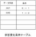
図2に状態変化条件テーブルの一例を示す。この例では、データ位置「001」のデータが「0」から「1」に変化したとき、またはデータ位置005のデータが「1」から「0」に変化したときに状態が変化したとすることを表している。この状態変化条件テーブル451には、従来のビルダを用いて値を設定することもできるが、他の方法で設定してもよい。 FIG. 2 shows an example of the state change condition table. In this example, it is assumed that the state changes when the data at the data position “001” changes from “0” to “1” or when the data at the
状態変化検出手段452は入出力データ処理手段44から受け取った入出力データの変化を監視し、状態変化条件テーブル451に設定された状態変化と合致した変化が発生すると、FIFO41から取得したシステム時刻から発生させたタイムスタンプを添付して、その旨をアラーム通知処理手段43に通知する。 The state
アラーム処理手段43は、この通知を受け取ると、そのことを制御ステーション3に通知する。制御ステーション3はマンマシンインターフェイス1にこの通知に基づくアラームを表示する。 Upon receiving this notification, the alarm processing means 43 notifies the
なお、この実施例では状態変化検出処理手段45をプロフィバス通信モジュール4に内蔵するようにしたが、他のモジュールに内蔵するようにしてもよく、また独立した機器として用いてもよい。要は、フィールド機器5の入出力データが簡単に得られる位置に配置すればよい。 In this embodiment, the state change detection processing means 45 is built in the Profibus communication module 4, but it may be built in another module or may be used as an independent device. In short, it may be arranged at a position where the input / output data of the
また、フィールド機器5が接続されるフィールドバスはプロフィバスに限定されず、ファウンデーションフィールドバス(Foundation Field Bus)等他のフィールドバスであってもよい。ファウンデーションフィールドバスにおいては、フィールド機器での自己診断による異常発生イベントは通知可能であるが、プロセスの異常発生については規定されてない。本発明を適用することにより、ファウンデーションフィールドバスでも同様のSOE機能を実現することができる。 The field bus to which the
また、この実施例では制御ステーションから定周期でシステム時刻を供給するようにしたが、他の時計機構を利用するようにしてもよい。 In this embodiment, the system time is supplied from the control station at a fixed cycle. However, another clock mechanism may be used.
1 マンマシンインターフェイス
11 アラーム表示
21 制御バス
22 IOバス
23 プロフィバス
3 制御ステーション
4 プロフィバス通信モジュール
41 FIFO
43 アラーム通知処理手段
44 入出力データ処理手段
45 状態変化検出処理手段
451 状態変化条件テーブル
452 状態変化検出手段
5 フィールド機器
1
43 Alarm notification processing means 44 Input / output data processing means 45 State change detection processing means 451 State change condition table 452 State change detection means 5 Field device
Claims (8)
Translated fromJapaneseフィールド機器の入出力データおよびシステム時刻が入力され、前記状態変化条件テーブルを参照して、前記入出力データの状態が前記状態が変化したことを検出する条件と合致したときに、前記システム時刻から生成したタイムスタンプを付した信号を出力する状態変化検出手段と、
を具備したことを特徴とする状態変化検出装置。A state change condition table storing conditions for detecting that the state has changed;
When the input / output data of the field device and the system time are input and the state change condition table is referenced and the state of the input / output data matches the condition for detecting that the state has changed, the system time is State change detection means for outputting a signal with a generated time stamp;
A state change detection apparatus comprising:
前記フィールド機器からプロセスデータが入力され、このプロセスデータから制御量を演算して出力する制御ステーションと、
状態が変化したことを検出する条件が格納される状態変化条件テーブルと、前記フィールド機器の入出力データおよび前記制御システムから出力されるシステム時刻が入力され、前記入出力データの状態が、前記状態が変化したことを検出する条件と合致したときに、前記システム時刻から生成したタイムスタンプを付した信号を前記制御ステーションに出力する状態変化検出器とで構成される状態変化検出装置と、
を具備したことを特徴とするプロセス制御システム。A fieldbus to which field devices are connected;
Process data is input from the field device, a control station that calculates and outputs a control amount from the process data, and
A state change condition table storing conditions for detecting that the state has changed, input / output data of the field device and a system time output from the control system are input, and the state of the input / output data is the state A state change detecting device configured to output a signal with a time stamp generated from the system time to the control station when the condition for detecting that the change has occurred is met,
A process control system comprising:
7. The process control system according to claim 5, wherein the field bus is a foundation field bus.
Priority Applications (1)
| Application Number | Priority Date | Filing Date | Title |
|---|---|---|---|
| JP2004139383AJP2005322015A (en) | 2004-05-10 | 2004-05-10 | State change detection device and process control system using the same |
Applications Claiming Priority (1)
| Application Number | Priority Date | Filing Date | Title |
|---|---|---|---|
| JP2004139383AJP2005322015A (en) | 2004-05-10 | 2004-05-10 | State change detection device and process control system using the same |
Publications (1)
| Publication Number | Publication Date |
|---|---|
| JP2005322015Atrue JP2005322015A (en) | 2005-11-17 |
Family
ID=35469256
Family Applications (1)
| Application Number | Title | Priority Date | Filing Date |
|---|---|---|---|
| JP2004139383AWithdrawnJP2005322015A (en) | 2004-05-10 | 2004-05-10 | State change detection device and process control system using the same |
Country Status (1)
| Country | Link |
|---|---|
| JP (1) | JP2005322015A (en) |
Cited By (2)
| Publication number | Priority date | Publication date | Assignee | Title |
|---|---|---|---|---|
| JP2009537900A (en)* | 2006-05-19 | 2009-10-29 | ウエスチングハウス・エレクトリック・カンパニー・エルエルシー | Computerized procedural system |
| JP2010182101A (en)* | 2009-02-05 | 2010-08-19 | Yokogawa Electric Corp | Field control system |
- 2004
- 2004-05-10JPJP2004139383Apatent/JP2005322015A/ennot_activeWithdrawn
Cited By (2)
| Publication number | Priority date | Publication date | Assignee | Title |
|---|---|---|---|---|
| JP2009537900A (en)* | 2006-05-19 | 2009-10-29 | ウエスチングハウス・エレクトリック・カンパニー・エルエルシー | Computerized procedural system |
| JP2010182101A (en)* | 2009-02-05 | 2010-08-19 | Yokogawa Electric Corp | Field control system |
Similar Documents
| Publication | Publication Date | Title |
|---|---|---|
| JP3945403B2 (en) | Servo motor drive control system | |
| JP2003058240A (en) | Sequence of events detection in process control system | |
| CN105320122A (en) | Monitoring control system and monitoring control method | |
| US8866431B2 (en) | Motor drive control apparatus | |
| WO2017077628A1 (en) | Function unit and control device | |
| KR101417197B1 (en) | Apparatus and method for positioning in Programmable Logic Controller, and PLC system using thereof | |
| JP2005322015A (en) | State change detection device and process control system using the same | |
| JP5710713B2 (en) | Motor control system | |
| US6999833B2 (en) | Computer system for realtime and non-realtime programs | |
| JP4389273B2 (en) | PLC function built-in drive controller | |
| JP5296419B2 (en) | How to change the ladder program | |
| JP2014038562A (en) | Numerical control device with maintenance function during hmi abnormality | |
| JP6984422B2 (en) | Signal processing device and control method of signal processing device | |
| JP2006350768A (en) | Motion control system | |
| JP6524363B1 (en) | Motor drive control device | |
| JP6608019B2 (en) | Functional unit and control device | |
| JP2006048284A (en) | Programmable controller device and synchronization method with option module | |
| JP2001222308A (en) | Numerical control system | |
| KR20160141970A (en) | Apparatus adjusting output of analog output module | |
| WO2005076993A3 (en) | Computer presentation and command integration apparatus and method | |
| JP2019159753A (en) | Control device, control method, and control program | |
| JP2733569B2 (en) | Serial synchronous communication system | |
| JP2843327B2 (en) | Process control equipment | |
| US7450088B2 (en) | Apparatus and method for generating digital pulse | |
| JP2005276121A (en) | Serial encoder converter and network servo system equipped with the same. |
Legal Events
| Date | Code | Title | Description |
|---|---|---|---|
| A621 | Written request for application examination | Free format text:JAPANESE INTERMEDIATE CODE: A621 Effective date:20060329 | |
| A977 | Report on retrieval | Free format text:JAPANESE INTERMEDIATE CODE: A971007 Effective date:20080911 | |
| A131 | Notification of reasons for refusal | Free format text:JAPANESE INTERMEDIATE CODE: A131 Effective date:20080925 | |
| A761 | Written withdrawal of application | Free format text:JAPANESE INTERMEDIATE CODE: A761 Effective date:20081105 |