JP2005307485A - Antenna device and portable keyless device - Google Patents
Antenna device and portable keyless deviceDownload PDFInfo
- Publication number
- JP2005307485A JP2005307485AJP2004123203AJP2004123203AJP2005307485AJP 2005307485 AJP2005307485 AJP 2005307485AJP 2004123203 AJP2004123203 AJP 2004123203AJP 2004123203 AJP2004123203 AJP 2004123203AJP 2005307485 AJP2005307485 AJP 2005307485A
- Authority
- JP
- Japan
- Prior art keywords
- antenna
- main body
- transmission
- receiving
- body case
- Prior art date
- Legal status (The legal status is an assumption and is not a legal conclusion. Google has not performed a legal analysis and makes no representation as to the accuracy of the status listed.)
- Pending
Links
- 230000005540biological transmissionEffects0.000claimsabstractdescription60
- 230000002093peripheral effectEffects0.000claimsdescription8
- 230000000694effectsEffects0.000description4
- 239000002184metalSubstances0.000description3
- 238000000034methodMethods0.000description3
- 230000002411adverseEffects0.000description1
- 238000010586diagramMethods0.000description1
- 230000001939inductive effectEffects0.000description1
- 239000011347resinSubstances0.000description1
- 229920005989resinPolymers0.000description1
- 230000035945sensitivityEffects0.000description1
- 239000000758substrateSubstances0.000description1
Images


Landscapes
- Lock And Its Accessories (AREA)
- Variable-Direction Aerials And Aerial Arrays (AREA)
- Details Of Aerials (AREA)
Abstract
Description
Translated fromJapanese本発明は、アンテナ装置及びキーを用いず、例えば車両のドアをロック・アンロックする携帯型キーレス装置に関する。 The present invention relates to a portable keyless device that locks and unlocks a vehicle door, for example, without using an antenna device and a key.
従来、この種の携帯型キーレス装置として、特許文献1と2に示されたものがある。 Conventionally, as this type of portable keyless device, there are those shown in Patent Documents 1 and 2.
この特許文献1に示された携帯型キーレス装置は、自動車等に搭載された車載機と、ユーザが別個に携帯している携帯機とを利用して無線信号により、通信が行われていた。 In the portable keyless device disclosed in Patent Document 1, communication is performed by radio signals using an in-vehicle device mounted in an automobile or the like and a portable device that is carried separately by a user.
また、特許文献2に示された携帯型キーレス装置において、携帯機の送信アンテナの増設により、キーレス装置の動作性能の確保、送信アンテナの送信機能を向上させる方法が提案されている。 Further, in the portable keyless device disclosed in Patent Document 2, a method has been proposed in which the operation performance of the keyless device is secured and the transmission function of the transmission antenna is improved by increasing the transmission antenna of the portable device.
しかしながら、このような方法を用いた携帯型キーレス装置の送信アンテナが、SW(スイッチ)操作時に手で覆われてしまう部分に配置されていた。 However, the transmitting antenna of the portable keyless device using such a method has been arranged in a portion that is covered with a hand when the SW (switch) is operated.
従って、送信のとき、送信アンテナからの送信出力が低下してしまい、交信に不具合な影響を与える虞があった。 Therefore, at the time of transmission, the transmission output from the transmission antenna is lowered, and there is a possibility of adversely affecting the communication.
また、携帯型キーレス装置における送信アンテナ増設用スペースが必要となる。その一方、送信アンテナを増設して送信機能を向上させるとすると、必要以上の駆動電源が消耗される虞があった。
そこで、本発明の目的は、上述のような不具合を鑑み、送信アンテナが送信をするとき、送信出力を向上し、正常な動作を確保可能なアンテナ装置及び携帯型キーレス装置を提供することにある。 Accordingly, an object of the present invention is to provide an antenna device and a portable keyless device capable of improving transmission output and ensuring normal operation when a transmission antenna performs transmission in view of the above-described problems. .
上記課題を解決するために、請求項1に記載のアンテナ装置は、送信アンテナと、三方向に配置された受信アンテナ本体を有する受信アンテナとを備え、
前記送信アンテナが前記受信アンテナのいずれか一つの受信アンテナ体に沿って延びるように配設されていることを特徴とする。In order to solve the above problems, an antenna device according to claim 1 includes a transmission antenna and a reception antenna having a reception antenna body arranged in three directions,
The transmitting antenna is arranged to extend along any one of the receiving antenna bodies.
請求項2に記載のアンテナ装置は、請求項1に記載のアンテナ装置において、前記送信アンテナと受信アンテナとが本体ケース内に配置され、前記本体ケースの内周縁に溝が形成され、前記送信アンテナが前記溝の中に配設され、前記受信アンテナが前記本体ケースに略ループ状に配設されていることを特徴とする。 The antenna device according to claim 2 is the antenna device according to claim 1, wherein the transmission antenna and the reception antenna are arranged in a main body case, and a groove is formed in an inner peripheral edge of the main body case. Is arranged in the groove, and the receiving antenna is arranged in a substantially loop shape in the main body case.
請求項3に記載のアンテナ装置は、請求項2に記載のアンテナ装置において、前記受信アンテナ体が前記本体ケースに取付けられた回路基板に互いに直交する方向に配設され、前記送信アンテナが内周縁の溝に配設されていることを特徴とする。 The antenna device according to claim 3 is the antenna device according to claim 2, wherein the receiving antenna body is disposed in directions orthogonal to each other on a circuit board attached to the main body case, and the transmitting antenna is an inner peripheral edge. It is characterized by being disposed in the groove.
請求項4に記載のアンテナ装置を有する携帯型キーレス装置は、送信アンテナと、三方向に配設された受信アンテナ本体を有する受信アンテナと、送受信を制御する回路とを備える携帯型キーレス装置あって、前記送信アンテナが前記受信アンテナのいずれか一つの受信アンテナ体に沿って延びるように配設されていることを特徴とする。 A portable keyless device having the antenna device according to claim 4 is a portable keyless device comprising a transmission antenna, a reception antenna having a reception antenna body arranged in three directions, and a circuit for controlling transmission and reception. The transmitting antenna is arranged so as to extend along any one of the receiving antenna bodies.
請求項5に記載のアンテナ装置を有する携帯型キーレス装置は、請求項4に記載のアンテナ装置を有する携帯型キーレス装置において、前記送信アンテナと受信アンテナとが本体ケース内に配置され、前記本体ケースの内周縁に溝が形成され、前記送信アンテナが前記溝の中に配設され、前記受信アンテナ体の少なくとも一つが前記本体ケース内周縁に沿って、前記送信アンテナの一部と隣接してループ状に配設されていることを特徴とする。 A portable keyless device having the antenna device according to claim 5 is the portable keyless device having the antenna device according to claim 4, wherein the transmitting antenna and the receiving antenna are arranged in a main body case, A groove is formed in the inner periphery of the antenna, the transmitting antenna is disposed in the groove, and at least one of the receiving antenna bodies is looped along the inner periphery of the main body case and adjacent to a part of the transmitting antenna. It is characterized by being arranged in a shape.
本発明の請求項1によれば、アンテナ装置は、送信アンテナと、三方向に配設された受信アンテナ本体を有する受信アンテナとを備え、前記送信アンテナが前記受信アンテナのいずれか一つの受信アンテナ体に沿って延びるように配設されている。つまり、送信アンテナは、操作時に手で覆われないように、配置されているため、送信出力が向上され、正常な交信を行うことができる。 According to claim 1 of the present invention, an antenna device includes a transmission antenna and a reception antenna having a reception antenna body arranged in three directions, and the transmission antenna is any one of the reception antennas. It is arranged so as to extend along the body. That is, since the transmission antenna is arranged so as not to be covered with a hand during operation, the transmission output is improved and normal communication can be performed.
また、本発明の請求項2によれば、前記送信アンテナと受信アンテナとが本体ケース内に配置され、前記本体ケースの内周縁に溝が形成され、前記送信アンテナが前記溝の中に配設され、前記受信アンテナが前記本体ケースに略ループ状に配設されていることにより、アンテナ装置の構造がコンパクト化される。また、一方の受信側アンテナは、予め他方の方向のアンテナとともに、電子部品が設けられた基板等とともに、サブアセンブリつまり仮組立てが容易にでき、より組み立て効率が良好である。 According to a second aspect of the present invention, the transmitting antenna and the receiving antenna are disposed in a main body case, a groove is formed in an inner peripheral edge of the main body case, and the transmitting antenna is disposed in the groove. In addition, since the receiving antenna is disposed in a substantially loop shape on the main body case, the structure of the antenna device is made compact. In addition, one receiving-side antenna can be easily sub-assembled, that is, temporarily assembled together with an antenna in the other direction in advance, along with a substrate on which electronic components are provided, and the assembly efficiency is better.
以下、本発明のアンテナ装置を携帯型キーレス装置に適用した好適な実施形態を、図面を参照して詳細に説明する。 DESCRIPTION OF EMBODIMENTS Hereinafter, a preferred embodiment in which an antenna device of the present invention is applied to a portable keyless device will be described in detail with reference to the drawings.
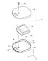
本発明に係る携帯型キーレス装置10は、図1〜2に示すように、凹部20を有する本体ケース30と、この本体ケースに対して開閉可能な蓋40と、本体ケース30に取付けられたアンテナ装置50と、凹部20に取付けられた回路基板60と、この回路基板上に取付けられ送受信回路を有する制御ユニット70とを備える。 As shown in FIGS. 1 and 2, the portable
本体ケース30と蓋40は同種類の樹脂から成る。本体ケース30と蓋40の一端には、夫々本体ケース30と蓋40と一体の開口32を有する突起部34が設けられている。 The
この開口は、図示せずのキーホルダに用いられるものである。蓋40はボルトBSにより本体ケース30に取付けられる。 This opening is used for a key holder (not shown). The
また、図2に示すように、アンテナ装置50は、受信アンテナ54と送信アンテナ55とを備える。この送受信アンテナは金属線からなる。 As shown in FIG. 2, the
受信アンテナ54は、互いに直交するX、Z、Yの方向に配設される3個の受信アンテナ体51、52と53とを有する。この3個の受信アンテナ体は夫々ループ状に形成されている。 The receiving
この3個の受信アンテナ体は、回路基板上60に図2に示すように設けられている。 The three receiving antenna bodies are provided on the
送信アンテナ55は、本体ケース30の内周壁36に設けられた溝38に沿ってループ状に配設されている。同じく、突起部34にも溝39が形成され、送信アンテナ55の一部が配設される。 The
即ち、送信アンテナ55は、回路基板60上に互いに直交するX、Y、Zの3方向のアンテナ体51、52と53のうち、例えば少なくともZ方向のアンテナ体52の略全周囲に亘り囲むように配設されている。つまり、本体ケース30と蓋40との組立体を持ったとき、手で覆われないような構造になっている。 In other words, the transmitting
そのため、送信時に前記受信アンテナの例えばZ受信アンテナ体52を誘起させ、送信アンテナとして兼用することができる。よって、送信アンテナの送信出力が向上され、正常な交信を行うことができる。 Therefore, for example, the Z
ここでは、受信アンテナと送信アンテナとを誘起させる方法について、従来と同様であるため、省略する。 Here, the method for inducing the receiving antenna and the transmitting antenna is the same as that in the prior art, and is therefore omitted.
また、このような構造を用いると、別個の送信アンテナを増設ける必要がない。 Further, when such a structure is used, it is not necessary to additionally provide separate transmission antennas.
送信アンテナと受信アンテナと回路基板の組立てが容易にでき、組立て効率が高くなる効果も得られる。 Assembling of the transmitting antenna, the receiving antenna, and the circuit board can be facilitated, and the effect of increasing the assembling efficiency can be obtained.
上記の発明の好適な実施の形態では、送信アンテナと受信アンテナの配設において、送信アンテナ55と受信アンテナ54の少なくとも一個が略重複するような構成となっている。 In the preferred embodiment of the present invention, in the arrangement of the transmission antenna and the reception antenna, at least one of the
次に、送信アンテナと受信アンテナ配設の重複構造において、図4〜6に示す変形実施例をもって簡単に述べる。 Next, the overlapping structure of the transmitting antenna and the receiving antenna will be briefly described with the modified embodiments shown in FIGS.
変形実施例1
図4に示すように、送信アンテナ55が本体ケース30の内周壁に埋設される。受信アンテナ54の少なくとも受信アンテナ体52が回路基板60外周を囲むように延び、略ループ状に送信アンテナ55と隣接して配設される構造にしても良い。Modified Example 1
As shown in FIG. 4, the
即ち、本体ケース30内外方向で重複するように配置されている。 That is, they are arranged so as to overlap in the inside and outside directions of the
これにより、送信アンテナは手等で覆われない構造が実現でき、送信アンテナ55の送信出力が向上される効果が得られる。 Thereby, the structure which a transmission antenna does not cover with a hand etc. is realizable, and the effect that the transmission output of
変形実施例2
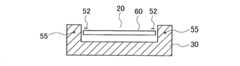
または、図5に示すように、送信アンテナ55は回路基板60の本体ケース30の凹部30の下部に埋設されている。受信アンテナ体52が回路基板60上の対向位置に配設され、蓋40を合わせる面内外方向で重複しても良い。Modified Example 2
Alternatively, as shown in FIG. 5, the
これにより、送信アンテナは手等で覆われない構造が実現でき、送信アンテナ55の送信出力が向上される効果が得られる。また、キーレス装置のコンパクト化が実現可能である。 Thereby, the structure which a transmission antenna does not cover with a hand etc. is realizable, and the effect that the transmission output of
変形実施例3
図6に示すように、送信アンテナ55が本体ケース30内周壁に埋設され、受信アンテナ34が回路基板60の外周沿いに配設され、本体ケース30内外方向で重複するように配置されても良い。Modified Example 3
As shown in FIG. 6, the transmitting
または、本体ケース30と蓋40の突起部に送信アンテナ55が挟持されるような図示しない溝が形成され、この溝に送信アンテナ55が挟持され構造にしても良い。 Alternatively, a groove (not shown) in which the
これら構造からも、別個の送信アンテナを増設する必要がないという効果が得られる。また、送信アンテナの送信出力が向上され、正常な交信を行うことができる。 Also from these structures, there is an effect that it is not necessary to add a separate transmission antenna. Further, the transmission output of the transmission antenna is improved, and normal communication can be performed.
なお、回路基板60は、本体ケース30の凹部20に設けられた図示せずのボスに支持され本体ケースに取付けられている。 The
送信アンテナ55が、図3に示すように、アンテナ配線を介して回路基板60に設けられた送信部80に接続される。 As shown in FIG. 3, the
また、受信アンテナ54が、アンテナ配線を介して回路基板60に設けられた受信部90に接続される。 In addition, the receiving
制御ユニット70は、携帯型キーレス装置全体を制御する手段であり、送受信部等をプログラム制御する中央処理装置CPUと、送受信プログラムや車両送受機100の識別コード等を記憶するメモリとを有する。 The
制御ユニット70には、受信アンテナ55及び受信部90が、信号線で接続される。受信アンテナ54が車両送受機100から送信される識別信号112を受信する。 The
受信部90は受信アンテナ54で受信した識別信号112を復調等して制御ユニット70へ送る機能を有する。 The receiving
また、制御ユニット70には、車載送受信機110へ応答識別信号22を送信する送信アンテナ55及び送信部80が信号線で接続される。 In addition, a
送信部80は、制御ユニット70から送信される識別ID信号等を含んだデータを所定の無線周波数の応答識別信号22に変調等して、送信アンテナ55を介して送信させる機能を有する。 The
本発明では、ループ状アンテナを望ましい実施形態として述べているが、その構成、形状、及び取付け位置は、良好なアンテナ感度を得られる構成であれば本実施の形態に限定されない。 In the present invention, a loop antenna is described as a preferred embodiment, but the configuration, shape, and mounting position thereof are not limited to the present embodiment as long as good antenna sensitivity can be obtained.
本実施形態では、送信アンテナと受信アンテナは金属線からなっているが、細幅の金属板により構成されても良い。 In this embodiment, the transmitting antenna and the receiving antenna are made of metal wires, but may be made of a narrow metal plate.
本発明では、リモコンスイッチを用いず、車載側と、携帯機側の認識IDにより交信操作行われるようになっているが、リモコンスイッチとキーとが一体タイプとするような構造にしても良い。 In the present invention, the communication operation is performed by the recognition ID on the vehicle-mounted side and the portable device side without using the remote control switch. However, the remote control switch and the key may be integrated.
10 携帯型キーレス装置
20 凹部
30 本体ケース
40 蓋
50 アンテナ装置
51、52、53 受信アンテナ体
55 送信アンテナ
60 回路基板DESCRIPTION OF
Claims (5)
Translated fromJapanese三方向に配設された受信アンテナ本体を有する受信アンテナとを備え、
前記送信アンテナが前記受信アンテナのいずれか一つの受信アンテナ体に沿って延びるように配設されていることを特徴とするアンテナ装置。A transmitting antenna;
A receiving antenna having a receiving antenna body arranged in three directions,
The antenna apparatus, wherein the transmitting antenna is disposed so as to extend along any one of the receiving antenna bodies.
三方向に配設された受信アンテナ本体を有する受信アンテナと、
送受信を制御する回路と、を備える携帯型キーレス装置あって、
前記送信アンテナが前記受信アンテナのいずれか一つの受信アンテナ体に沿って延びるように配設されていることを特徴とする携帯型キーレス装置。A transmitting antenna;
A receiving antenna having a receiving antenna body arranged in three directions;
A portable keyless device comprising a circuit for controlling transmission and reception,
A portable keyless device, wherein the transmitting antenna is disposed so as to extend along any one of the receiving antenna bodies.
Priority Applications (1)
| Application Number | Priority Date | Filing Date | Title |
|---|---|---|---|
| JP2004123203AJP2005307485A (en) | 2004-04-19 | 2004-04-19 | Antenna device and portable keyless device |
Applications Claiming Priority (1)
| Application Number | Priority Date | Filing Date | Title |
|---|---|---|---|
| JP2004123203AJP2005307485A (en) | 2004-04-19 | 2004-04-19 | Antenna device and portable keyless device |
Publications (1)
| Publication Number | Publication Date |
|---|---|
| JP2005307485Atrue JP2005307485A (en) | 2005-11-04 |
Family
ID=35436566
Family Applications (1)
| Application Number | Title | Priority Date | Filing Date |
|---|---|---|---|
| JP2004123203APendingJP2005307485A (en) | 2004-04-19 | 2004-04-19 | Antenna device and portable keyless device |
Country Status (1)
| Country | Link |
|---|---|
| JP (1) | JP2005307485A (en) |
Cited By (2)
| Publication number | Priority date | Publication date | Assignee | Title |
|---|---|---|---|---|
| JP2007224664A (en)* | 2006-02-24 | 2007-09-06 | Tokai Rika Co Ltd | Strength reinforcing structure of electronic key |
| JP2014187524A (en)* | 2013-03-22 | 2014-10-02 | Yamaha Motor Co Ltd | Small-sized vehicle remote control key unit, small-sized vehicle remote control key system, and small-sized vehicle |
- 2004
- 2004-04-19JPJP2004123203Apatent/JP2005307485A/enactivePending
Cited By (2)
| Publication number | Priority date | Publication date | Assignee | Title |
|---|---|---|---|---|
| JP2007224664A (en)* | 2006-02-24 | 2007-09-06 | Tokai Rika Co Ltd | Strength reinforcing structure of electronic key |
| JP2014187524A (en)* | 2013-03-22 | 2014-10-02 | Yamaha Motor Co Ltd | Small-sized vehicle remote control key unit, small-sized vehicle remote control key system, and small-sized vehicle |
Similar Documents
| Publication | Publication Date | Title |
|---|---|---|
| CN111918797B (en) | Method and system for providing bluetooth-based Passive Entry and Passive Start (PEPS) for a vehicle | |
| JP5375158B2 (en) | Transceiver and electronic key having the transceiver | |
| US7679571B2 (en) | Antenna device and door handle device | |
| JP3696866B2 (en) | Door opener | |
| CN106458159A (en) | Vehicular keyless entry system | |
| JP4695527B2 (en) | Strengthening structure of electronic key | |
| JP2010216176A (en) | Door handle device for vehicle | |
| US8594597B2 (en) | Portable transmitter powered by button battery | |
| JP2008079118A (en) | Vehicle antenna apparatus | |
| JP2005307485A (en) | Antenna device and portable keyless device | |
| JP2003253934A (en) | Electronic key system | |
| JP3159185B2 (en) | Transmitter and receiver | |
| JP2009159211A (en) | Antenna device | |
| JP2015048691A (en) | Vehicle security device | |
| JP2009147543A (en) | Onboard antenna | |
| JP4037424B2 (en) | Vehicle communication device | |
| JP2005133413A (en) | Door opening/closing device | |
| JP3861692B2 (en) | RFID tag reader | |
| JP4680723B2 (en) | Communication terminal | |
| JPH09104260A (en) | On-vehicle electronic control device | |
| JP2006328899A (en) | Door handle device | |
| JP2007016518A (en) | Vehicle communication device | |
| CN101888012A (en) | Installation structure of the antenna unit | |
| JPS61261933A (en) | portable wireless transceiver | |
| JP3937963B2 (en) | Antenna device |