JP2005302384A - Waterproof keyboard - Google Patents
Waterproof keyboardDownload PDFInfo
- Publication number
- JP2005302384A JP2005302384AJP2004113433AJP2004113433AJP2005302384AJP 2005302384 AJP2005302384 AJP 2005302384AJP 2004113433 AJP2004113433 AJP 2004113433AJP 2004113433 AJP2004113433 AJP 2004113433AJP 2005302384 AJP2005302384 AJP 2005302384A
- Authority
- JP
- Japan
- Prior art keywords
- frame
- waterproof layer
- keyboard
- key
- circuit support
- Prior art date
- Legal status (The legal status is an assumption and is not a legal conclusion. Google has not performed a legal analysis and makes no representation as to the accuracy of the status listed.)
- Pending
Links
- 239000012528membraneSubstances0.000claimsabstractdescription19
- 230000002093peripheral effectEffects0.000claimsabstractdescription18
- 229920003002synthetic resinPolymers0.000claimsabstractdescription16
- 239000000057synthetic resinSubstances0.000claimsabstractdescription16
- 238000007789sealingMethods0.000claimsabstractdescription9
- 239000000428dustSubstances0.000claimsabstractdescription7
- 230000007246mechanismEffects0.000claimsdescription7
- 239000010409thin filmSubstances0.000abstractdescription16
- 239000000463materialSubstances0.000description5
- 229920002379silicone rubberPolymers0.000description5
- 239000004945silicone rubberSubstances0.000description5
- 239000000758substrateSubstances0.000description5
- XLYOFNOQVPJJNP-UHFFFAOYSA-NwaterChemical compoundOXLYOFNOQVPJJNP-UHFFFAOYSA-N0.000description5
- 125000006850spacer groupChemical group0.000description4
- 239000007788liquidSubstances0.000description3
- 238000004078waterproofingMethods0.000description3
- 229910052782aluminiumInorganic materials0.000description2
- XAGFODPZIPBFFR-UHFFFAOYSA-NaluminiumChemical compound[Al]XAGFODPZIPBFFR-UHFFFAOYSA-N0.000description2
- 229910052751metalInorganic materials0.000description2
- 239000002184metalSubstances0.000description2
- 238000012856packingMethods0.000description2
- 239000004033plasticSubstances0.000description2
- 229920003023plasticPolymers0.000description2
- 229920001084poly(chloroprene)Polymers0.000description2
- -1polyethylene terephthalatePolymers0.000description2
- 229920000139polyethylene terephthalatePolymers0.000description2
- 239000005020polyethylene terephthalateSubstances0.000description2
- 239000004698PolyethyleneSubstances0.000description1
- 238000005452bendingMethods0.000description1
- 238000007599dischargingMethods0.000description1
- 230000000694effectsEffects0.000description1
- 239000013013elastic materialSubstances0.000description1
- 229920001971elastomerPolymers0.000description1
- 239000012777electrically insulating materialSubstances0.000description1
- 238000005516engineering processMethods0.000description1
- 235000012438extruded productNutrition0.000description1
- 238000004519manufacturing processMethods0.000description1
- 239000011159matrix materialSubstances0.000description1
- 229920000573polyethylenePolymers0.000description1
- 229920000642polymerPolymers0.000description1
- 229920001296polysiloxanePolymers0.000description1
- 229920000915polyvinyl chloridePolymers0.000description1
- 239000004800polyvinyl chlorideSubstances0.000description1
- 229920005989resinPolymers0.000description1
- 239000011347resinSubstances0.000description1
- 238000011282treatmentMethods0.000description1
Images


Classifications
- H—ELECTRICITY
- H01—ELECTRIC ELEMENTS
- H01H—ELECTRIC SWITCHES; RELAYS; SELECTORS; EMERGENCY PROTECTIVE DEVICES
- H01H13/00—Switches having rectilinearly-movable operating part or parts adapted for pushing or pulling in one direction only, e.g. push-button switch
- H01H13/02—Details
- H01H13/04—Cases; Covers
- H01H13/06—Dustproof, splashproof, drip-proof, waterproof or flameproof casings
- H01H13/063—Casings hermetically closed by a diaphragm through which passes an actuating member
- H—ELECTRICITY
- H01—ELECTRIC ELEMENTS
- H01H—ELECTRIC SWITCHES; RELAYS; SELECTORS; EMERGENCY PROTECTIVE DEVICES
- H01H2223/00—Casings
- H01H2223/002—Casings sealed
- H—ELECTRICITY
- H01—ELECTRIC ELEMENTS
- H01H—ELECTRIC SWITCHES; RELAYS; SELECTORS; EMERGENCY PROTECTIVE DEVICES
- H01H2223/00—Casings
- H01H2223/002—Casings sealed
- H01H2223/003—Membrane embracing all keys
- H—ELECTRICITY
- H01—ELECTRIC ELEMENTS
- H01H—ELECTRIC SWITCHES; RELAYS; SELECTORS; EMERGENCY PROTECTIVE DEVICES
- H01H2231/00—Applications
- H01H2231/044—Under water
- H—ELECTRICITY
- H01—ELECTRIC ELEMENTS
- H01H—ELECTRIC SWITCHES; RELAYS; SELECTORS; EMERGENCY PROTECTIVE DEVICES
- H01H2233/00—Key modules
- H01H2233/07—Cap or button on actuator part
- H—ELECTRICITY
- H01—ELECTRIC ELEMENTS
- H01H—ELECTRIC SWITCHES; RELAYS; SELECTORS; EMERGENCY PROTECTIVE DEVICES
- H01H9/00—Details of switching devices, not covered by groups H01H1/00 - H01H7/00
- H01H9/02—Bases, casings, or covers
- H01H9/04—Dustproof, splashproof, drip-proof, waterproof, or flameproof casings
- H01H9/041—Casings hermetically closed by a diaphragm through which passes an actuating member
Landscapes
- Input From Keyboards Or The Like (AREA)
- Push-Button Switches (AREA)
Abstract
Description
Translated fromJapanese本発明は、キーボード、とくにコンピュータにデータや指示を手操作で入力するフルキーボード、テンキーパッドなどの手操作入力装置に関するものである。 The present invention relates to a manual operation input device such as a keyboard, particularly a full keyboard and a numeric keypad for manually inputting data and instructions to a computer.
従来、キーボードには、日常の生活防水から医療現場での使用などを含めて完全防水まで、様々な防水、防滴、防塵処理が施されたものがある。たとえば、特開平10-222267号公報(特許文献1)や特開平9-305281号公報(特許文献2)には、キースイッチの配設されたサポートパネルを覆う弾性体の防水カバーによってスイッチ素子部へのミスト状の油や水蒸気の侵入を防止するパソコン用のキーボードが開示されている。いずれも、防水カバーとサポートベースによって、両者の間にあるサポートパネルに配設されているスイッチ素子部を完全に覆うことで、防塵、防滴効果を達成している。キートップは、防水カバーの上方に配設され、キートップを押した時、弾性体の防水カバーを介してスイッチ素子部を押圧することになる。
特許文献1および2に記載のキーボードはいずれも、堅牢な防水機構であり、防水構造専用の部材を用意して組み立てる必要があり、したがって製造原価も高い。 Both the keyboards described in Patent Documents 1 and 2 are robust waterproof mechanisms, and it is necessary to prepare and assemble a member dedicated to the waterproof structure, and thus the manufacturing cost is high.
本発明はこのような従来技術の欠点を解消し、通常のキーボードと実質的に同等の操作感を維持しながら、簡略な構造で密閉度の高い防水キーボードを提供することを目的とする。 An object of the present invention is to provide a waterproof keyboard having a simple structure and a high degree of sealing while eliminating the drawbacks of the conventional technology and maintaining a feeling of operation substantially equivalent to that of a normal keyboard.
本発明による防水キーボードは、全体として矩形の平面形状を有し複数のキートップを支持する第1の枠体と、対応する複数のキー接点およびそれらの接続回路が配設された回路支持体と、平面形状に対応する平面形状を有し、回路支持体を支持する基体をなす第2の枠体と、第2の枠体に支持された状態で回路支持体と第1の枠体との間にあって第2の枠体と協働して該回路支持体を封止する防水層と、防水層を第2の枠体の周縁部に押圧する弾性長尺部材と、第1および第2の枠体を相互に固定する緊定手段とを含み、防水層は可撓性のある合成樹脂からなり、緊定手段は、第1および第2の枠体の間に弾性長尺部材を介在させて第1および第2の枠体を相互に押圧し、これによって防水層および第2の枠体で回路支持体を封止し、回路支持体を塵埃および水分から保護する。 A waterproof keyboard according to the present invention has a rectangular frame shape as a whole, a first frame that supports a plurality of key tops, a circuit support that is provided with a plurality of corresponding key contacts and their connection circuits. A second frame having a planar shape corresponding to the planar shape and forming a base for supporting the circuit support, and the circuit support and the first frame supported by the second frame. A waterproof layer that seals the circuit support in cooperation with the second frame, an elastic elongate member that presses the waterproof layer against the peripheral edge of the second frame, and the first and second Tensioning means for fixing the frames to each other, the waterproof layer is made of a flexible synthetic resin, and the tensioning means includes an elastic elongate member interposed between the first and second frames. The first and second frames are pressed against each other, thereby sealing the circuit support with the waterproof layer and the second frame, The protection from dust and moisture bearing member.
本発明によればこのように、第2の枠体に支持された状態で回路支持体と第1の枠体との間にあって第2の枠体と協働して回路支持体を封止する防水層が弾性長尺部材によって第2の枠体の周縁部に押圧されることにより、簡略な構造で密閉度の高い防水キーボードが提供される According to the present invention, the circuit support is sealed in cooperation with the second frame between the circuit support and the first frame while being supported by the second frame. When the waterproof layer is pressed against the peripheral edge of the second frame by the elastic long member, a waterproof keyboard with a simple structure and a high sealing degree is provided.
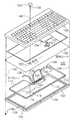
次に添付図面を参照して本発明による防水キーボードの実施例を詳細に説明する。図1を参照すると、本発明の実施例による防水キーボード100は、たとえば、パーソナルコンピュータなどに使用される106キーボードなどの標準キー配列の汎用フルキーボードである。 Next, embodiments of a waterproof keyboard according to the present invention will be described in detail with reference to the accompanying drawings. Referring to FIG. 1, a
キーボード100は、同図の下方に示すように基体としてのサポートベース102を有する。サポートベース102は、全体として平坦なほぼ矩形の平面形状を有する合成樹脂の一体成形品の枠体であり、下側および側面にはネジ穴103以外の開口はない。サポートベース102の内方部には、若干の深さの凹部104が形成されている。凹部104は、やはり矩形の平面形状をなし、その周縁部106が凹部の底面に対してわずかに隆起している。周縁部106には、図示のように周縁方向に溝108が形成され、溝108は、凹部104の底面を含む面方向に垂直な方向の断面が、本実施例では全体として半円形またはU字形であり、キーボード100を組み立てたとき、後述の合成樹脂薄膜シート134を介して押さえ部材110をこれに嵌合させる大きさを有している。この断面形状は、勿論他の形状でもよく、たとえば矩形なども有利に適用される。 The
サポートベース102の凹部104には、キースイッチメンブレーン112および114が間にスペーサ113を介して載置される。キースイッチメンブレーン112および114は、後に分かるように両者で対をなして回路支持体として機能し、これ自体、公知の構成であってよい。下側のメンブレーン112は、全体として凹部104の大きさとほぼ同じ平面寸法の矩形の可撓性合成樹脂シートであり、同図における上側の面には、キースイッチを構成する接点116の一方の電極118とその配線回路パターンが印刷されて形成されている。同様に、上側のメンブレーン114も、全体として下側のメンブレーン112とほぼ同じ平面寸法の矩形の可撓性合成樹脂シートであり、その下面には、キースイッチの接点116の他方の電極120とその配線回路パターンが印刷されて形成されている。スペーサ113は、電気的に絶縁性の材料で形成され、全体としてメンブレーン112または114とほぼ同じ平面寸法の矩形の平面形状を有する。スペーサ113には、接点116の電極118および120に対応する位置に、本実施例では円形の透孔(図示せず)が穿設され、これによって、後述のキートップ122が押された時、接点116における電極118および120が透孔を介して相互に接触し、そのキーに応じた電気回路を閉成する。 In the
メンブレーン112および114は対を成し、その一部、本実施例では1つの隅部に回路基板124が配設され、これに搭載された回路に接点116の配線回路パターン126が接続されている。回路基板124の回路には、接続コード128が接続されている。コード128は、図示のように、組み立てた状態では、サポートベース102の周縁部106に形成された溝130に収容され、孔132を通ってキーボード100の外部に出る。孔132とコード128との間も、パッキンまたは樹脂材などにより防水処理がされている。接続コード128は、コネクタ(図示せず)を介してパーソナルコンピュータなどの利用装置(図示せず)に接続される。 The
さて、本実施例では、これらの上方に可撓性および伸展性のある合成樹脂薄膜シート134が配設されている。この薄膜シート134は、たとえばポリエチレンテレフタラート(PET)、ポリ塩化ビニル、ポリエチレンなどの平坦な薄いフィルムからなり、基板124を含むメンブレーン114の上方からこれらを覆うように配設されて防水層として機能する。薄膜シート134は、その周縁の上方から押さえ部材110を溝108に挿入して嵌合させることにより、メンブレーン112および114とともにサポートベース108に固定される。薄膜シート134は全体として、サポートベース102の外形寸法とほぼ同じ平面寸法を有し、たとえば信越ポリマー株式会社から市販のポリラップ(商標)などのフィルム状シートが有利に適用される。このような長尺のシート状素材をそのまま、上述のように押さえ部材110で固定して、固定後、その周囲を適切な大きさに切断するようにしてもよい。 In the present embodiment, a flexible and stretchable synthetic resin
押さえ部材110は、たとえばシリコーンゴム、ネオプレンゴムなどの長尺ひも状の弾性合成樹脂からなり、内密またはスポンジ状であってよい。その長手方向に垂直な断面は、溝108の断面に合わせた円形または矩形などの形状でよい。押さえ部材110が薄膜シート134を介して溝108の内部に押し込まれると、その弾性により薄膜シート134がサポートベース102に堅固に固定される。 The
これらの上にキーパネル136が載置される。キーパネル136には多数のキートップ122が配設されこれらを可動的に保持する枠体であり、これによって、106キーボードまたはテンキーパッドが形成される。キートップ122は、その下部の突起138にドーム部材140を嵌合させて、これらが薄膜シート134を介して対応する接点116の上に載置される。これによって、1つのキーに対応するキースイッチが構成される。 A
ドーム部材140は、シリコーンゴムなどの弾性合成樹脂で形成され、中空で半球状の形状の頂部に突起を有している。ドーム部材140は、この半球形状と材質の弾性によってクリックアクションを達成し、キートップ122を上方から弾性に抗して押圧した時に接点116の1対の電極118および120が相互に接触するようにこれらを押圧し、また、押圧力を解放すると弾性による反発力でキートップ122が原位置に復帰する、いわゆるドームクリック機構を構成している。このドーム部材140によって得られる反発力は、快適な感触のキータッチを生ずる。そのとき、薄膜シート134は、十分に薄く、かつ可撓性および伸展性ないし展延性を有している。したがって、キートップ122の上下動およびそれによるドーム部材140の変形に十分耐えることができ、かつメンブレーン112および114や基板124で形成される電気回路および機械的接点を外部から封止して、上下左右、いずれの方向からの塵埃や水分の侵入を阻止することができる。 The
図面には、キートップ122、ドーム部材140および接点116などが1組しか示されていないが、これは図の煩雑化を避けるためであって、実際には、これらは多数、たとえば112個も配設されて、キーマトリクスを構成していることは、言うまでもない。また、各図において、同様の構成要素は、同じ参照符号で示す。 In the drawing, only one set of the
これらの各構成要素を、図に一点鎖線142、144および146で示すように組み立てて、最終的には、サポートベース102にキーパネル136を嵌合させ、両者を周縁の適切な複数箇所でビス148などの緊締手段にて互に対して固定する。これによって、キーパネル136の周縁部は、押さえ部材110を介してサポートベース102の周縁部106に対して適切な圧力で押圧される。この押圧力と押さえ部材110の弾性により、完全な防水、封止機構が達成され、防水キーボード100が完成する。勿論、キーボード100の中央付近でもビス留めをしてよいが、防水の観点からは、中央付近にビス穴は少ない方がよく、本実施例では、周縁部だけで全体を固定している。 Assemble each of these components as shown by the alternate long and
図2を参照すると、本発明によるキーボードの他の実施例は、薄膜シート134およびドーム部材140に代わって、防水シート150が配設されている以外は、図1に示す実施例と同じ構成である。防水シート150は、サポートベース102の外形寸法とほぼ同じ平面寸法を有し、たとえばシリコーンまたはネオプレンなどの弾性のある合成樹脂シート部材からなる防水層である。その厚さは、たとえば0.7 mm程度であり、基板124を含むメンブレーン114の上方からこれらを覆うように配設されている。 Referring to FIG. 2, another embodiment of the keyboard according to the present invention has the same configuration as the embodiment shown in FIG. 1 except that a
防水シート150には、図示のようにドーム部材140(図1)に相当する多数のドーム142が凸状に一体成形されている。これによって、個別のドーム部材140で得られるキータッチと同様の快適な感触を生ずる。また、回路基板124に相当する位置には、図2の上方から見た凸部154が回路基板124に対応する形状で、これも一体形成されている。凸部154は、その下側が、同図からは見えないが、凹部をなしてその内部に基板124およびそれに搭載されている集積回路や発光ダイオードなどの回路部品を収納することができる形状を有している。防水シート150は、前述の薄膜シート134と同様にして、その周縁の上方から押さえ部材110を溝108に挿入して嵌合させることにより、メンブレーン112および114とともにサポートベース108に固定される。押さえ部材110および溝108はなくてもよい。または、押さえ部材110に相当する形状部を防水シート150の周縁に一体的に形成し、この形状部を溝108に係合させることによって、防水シート150をサポートベース102に固定するように構成してもよい。 As shown in the figure, a number of
上述の実施例はいずれも、薄膜シート134または防水シート150などの可撓性および伸展性のある防水層が押さえ部材110によってサポートベース102に堅固に固定されることによって、メンブレーン112および114や基板124で形成される電気回路および機械的接点を外部から封止し、上下左右、いずれの方向からの塵埃や水分の侵入を阻止する、防水、防塵、防滴機構を実現している。 In any of the above-described embodiments, the
図3を参照すると、図1に示す実施例におけるキーパネル136の1つの隅部、たとえば192に形成された排液孔190が示されている。これは、隅部192を図1における下方から見た状態であり、サポートベース102に対してキーパネル136を嵌合させて組み立てたとき、サポートベース102の周縁部106の平面に対して溝190が空間を形成し、これによって排液孔が形成される。排液孔190は、いくぶん外部に向かって下方に傾斜し、防水シート150の上面に不用意に溜まった水などの液体をキーボード100の外部に排出する開口として機能する。なお、図3には、サポートベース102から挿入されたビス148がネジ係合するネジ穴194も図示されている。図2に示す実施例においても、このような排液孔190が形成されている。 Referring to FIG. 3, there is shown a drain hole 190 formed in one corner, for example, 192, of the
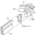
図4および図5を参照すると、本発明によるキーボードの他の実施例がそれぞれ部分側面図および部分斜視図で示されている。この実施例は、たとえば本出願人の保有する特許第3437958号に記載のようなフリーサイズのキーボードに有利に適用される。 4 and 5, another embodiment of the keyboard according to the present invention is shown in partial side view and partial perspective view, respectively. This embodiment is advantageously applied to a free-size keyboard such as that described in Japanese Patent No. 3437958 owned by the present applicant.
この実施例のキーボード300は、スイッチ基板302に多数のキースイッチ304が支持され、スイッチ基板302は、長尺状のフレーム306の溝345に嵌合することによって支持されている。スイッチ基板302には、図1に示す実施例と同様の回路基板328も支持されている。回路基板328は、たとえばキーボードエンコーダなどの回路部品348が搭載されている。 In the
キースイッチ304は、防水シート308を介してキートップ310に機構的に連結され、キートップ310は、同じくフレーム306に支持されているアルミニウムなどの金属板からなるキーパネル312にキートップガイド部材314を介して可動的に支持されている。キーパネル312は、コーナ部材330にビス346で固定される。これによってキートップ310は、同図における上下方向の摺動が可能である。キートップ310やキースイッチ304などは、実際には多数配列されているが、図では2組のみが示されている。 The
防水シート308は、図1に示す実施例について前述したように、たとえばシリコーンゴムなどの可撓性および伸展性のあるシート材からなり、キートップ310の下端320とキースイッチ304の上端322との間の高さに配設されている。防水シート308は、その周縁の上方から押さえ部材316を溝318に挿入して嵌合させることにより、フレーム306に固定される。 As described above with reference to the embodiment shown in FIG. 1, the
キートップ310の上方向の反発力は、キースイッチ304に内蔵されているバネ機構によって形成され、この反発力によってクリックアクションを達成している。より詳細には、キートップ310を上方から弾性に逆らって、たとえば50〜100g程度の力で押圧すると、その下端320がキースイッチ304を押下し、対応する接点の1対の電極を相互に接触させ、また、押圧力を解放すると反発力でキートップ310が原位置に復帰する、いわゆるメカニカルクリック機構を実現している。 The upward repulsive force of the
この実施例も同様に、防水シート308による可撓性および伸展性のある防水層が押さえ部材316によってフレーム306に堅固に固定されることによって、キースイッチ304や回路基板124で形成される電気回路および機械的接点を外部から封止し、上下左右、いずれの方向からも防水、防塵、防滴機能を達成している。 In this embodiment as well, an electric circuit formed by the
より詳細には、フレーム306の同図における下面には、長さ方向に沿って溝324が形成されている。溝324は、本実施例では、矩形またはU字状の縦方向断面形状を有し、これに防水紐326が収容される。防水紐326は、たとえばシリコーンゴムなどの弾性体からなり、後述の底板332が装着されたときにフレーム306と底板332との間に形成される間隙を封止する機能を有する。 More specifically, a
ところで、本実施例は、図6および図7からもわかるように、プラスチック押出し材である4本のフレーム306をプラスチック成形品の4個のコーナ部材330で相互に連結して全体として矩形の枠体が形成され、注文仕様に応じて自由なキー配列と大きさを有するフリーサイズのキーボード300である。底板332は、たとえばアルミニウムなどの金属板で形成され、その4隅がコーナ部材330にビス338によって固着され、さらに、押出し成形品である長尺状の押え板334によってフレーム306にも固定されている。 By the way, in this embodiment, as can be seen from FIGS. 6 and 7, four
フレーム306は、図8にその端面を示すが、同図の下面に長手方向に沿って溝340が形成されている。溝340には、これと対応するように押え板334に形成された、やはり長尺状の係合突起342が着脱可能に受け入れられる。係合突起342を矢印Dの方向に係合溝340の中へ挿入することによって、押え板334のフレーム340への装着状態では、底板332を押え板334でフレーム306の下面に押圧し、両者の間に介挿された弾性体防水紐326によって、底板332と防水シート308との間の空間344を封止し、その内部への下方からの液体や塵埃の侵入を防ぐことができる。押え板334はまた、底板332の周縁を均等に押圧するので、底板332の中央付近の撓みを防止することができる。 The end surface of the
上述の実施例では、押え板334は、フレーム306とは別体で構成されていた。しかし、両者を一体に成形してもよい。後者の場合、フレーム306は、底板332の端縁を受け入れて係合させる溝を有する構造をとる。これによっても、防水紐326によって堅固な水密構造が達成される。 In the above-described embodiment, the
図7に戻って、2本のフレーム306の連結は、コーナ部材330によって行なわれる。両者の連結部には、防水パッキン336が介挿され、これは、シリコーンゴムなどの弾性材料によって図示のような形状に形成されている。これによっても、底板332と防水シート308との間の空間344が封止されている。 Returning to FIG. 7, the two
フレーム306はさらに、図7の上側の面に長手方向に沿って溝350が形成されている。溝350は、矩形またはU字形の縦方向断面を有し、これには、防水紐352(図4)が受け入れられる。この防水紐352は、たとえば利用者の装置(図示せず)のパネルに本キーボード300を取り付ける適用例において、そのパネルとフレーム306の上面との間の間隙を封止し、これによって機器内部への浸水を防止するものである。 Further, the
本実施例においても、水抜き穴354が形成されている。水抜き穴354は、図1に示す実施例における排液孔190と同様の機能を有し、図9、図10および図11からわかるように、コーナ部材330に穿設されている。これは、キーボード300の4個のコーナ部材330のすべてに形成する必要はなく、それらのうちの、たとえば1個のコーナ部材に形成すればよい。より具体的には、コーナ部材330の成形時には盲穴でよく、フレームを組み立てる際、特定のコーナ部材のそれを貫通させればよい。水抜き穴354は、防水シート308の上面に不用意に溜まった水などの液体を矢印Bの方向へキーボード300の外部に排出する。上述した利用者装置のパネルにキーボード300を装着した適用例では、この水抜き穴354には、たとえばゴムなどのドレーンパイプを接続することができ、これによって排水が利用者装置の内部に侵入しないようにしている。 Also in this embodiment, a
キートップ310が矢印A(図4)の方向に押されると、キートップ310の下端320は防水シート308を下方に押し下げ、防水シート308は、図4における右側に示すように、その可撓性、伸展性もしくは展延性から撓むことができる。これによって、キースイッチ304は、その内部にある接点を閉成することができる。防水シート308を配設する高さは、同図からわかるように、キースイッチ304の上下動の範囲内にあるのがよく、好ましくは上下動の範囲のほぼ中央付近がよい。このような高さに防水シート308が配設される、同じくその高さに、フレーム306の溝318を形成し、この溝に押さえ部材316を係合させることによって、その高さに防水シート308を固定させる。このようにすることによって、防水シート308は、無理なく、つまり破損したり破けたりすることなく、キートップ310の下端320の上下動を受け入れ、キートップ310の上下動でキースイッチ304を作動させることができる。 When the
100、300 キーボード
102 サポートベース
110 押さえ部材
116 接点
124 回路基板
132 孔
134 薄膜シート
136 キーパネル
150 防水シート
190 排液孔
308 防水シート
310 キートップ
316 防水紐100, 300 keyboard
102 Support base
110 Holding member
116 contacts
124 circuit board
132 holes
134 Thin sheet
136 Key panel
150 tarpaulin
190 Drainage hole
308 tarpaulin
310 key top
316 waterproof string
Claims (8)
Translated fromJapanese対応する複数のキー接点およびそれらの接続回路が配設された回路支持体と、
前記平面形状に対応する平面形状を有し、前記回路支持体を支持する基体をなす第2の枠体と、
第2の枠体に支持された状態で前記回路支持体と第1の枠体との間にあって、第2の枠体と協働して該回路支持体を封止する防水層と、
該防水層を第2の枠体の周縁部に押圧する弾性長尺部材と、
第1および第2の枠体を相互に固定する緊定手段とを含み、
該防水層は可撓性のある合成樹脂からなり、
前記緊定手段は、第1および第2の枠体の間に前記弾性長尺部材を介在させて第1および第2の枠体を相互に押圧し、これによって前記防水層および第2の枠体で前記回路支持体を封止し、該回路支持体を塵埃および水分から保護することを特徴とするキーボード。A first frame body having a rectangular planar shape as a whole and supporting a plurality of key tops;
A plurality of corresponding key contacts and a circuit support provided with a connection circuit thereof;
A second frame having a planar shape corresponding to the planar shape and forming a base for supporting the circuit support;
A waterproof layer between the circuit support and the first frame in a state supported by the second frame and sealing the circuit support in cooperation with the second frame;
An elastic long member that presses the waterproof layer against the peripheral edge of the second frame;
Tensioning means for securing the first and second frames to each other;
The waterproof layer is made of a flexible synthetic resin,
The tightening means presses the first and second frames against each other with the elastic long member interposed between the first and second frames, and thereby the waterproof layer and the second frame. A keyboard, wherein the circuit support is sealed with a body to protect the circuit support from dust and moisture.
対応する複数のキー接点およびそれらの接続回路が配設された回路支持体と、
前記平面形状に対応する外形形状を有し、前記回路支持体を支持する枠体と、
該枠体に支持された回路支持体と前記キートップ支持体との間にあって、前記枠体と協働して該回路支持体を封止する防水層と、
前記枠体の周縁部と係合し、前記防水層を該周縁部に押圧する弾性長尺部材と、
前記枠体の前記回路支持体に対して前記キートップ支持体の反対側に位置して、前記枠体の開口を閉じる底板と、
該底板と前記枠体との間を封止して該底板を該枠体に固定する固定手段とを含み、
前記防水層は、可撓性のある合成樹脂からなり、
前記弾性長尺部材は、前記防水層を前記枠体の周縁部に封止し、該回路支持体を塵埃および水分から保護することを特徴とするキーボード。A key top support that has a rectangular planar shape as a whole and supports a plurality of key tops;
A plurality of corresponding key contacts and a circuit support provided with a connection circuit thereof;
A frame having an outer shape corresponding to the planar shape and supporting the circuit support;
A waterproof layer between the circuit support supported by the frame and the key top support, and sealing the circuit support in cooperation with the frame;
An elastic long member that engages with the peripheral edge of the frame and presses the waterproof layer against the peripheral edge;
A bottom plate that is positioned on the opposite side of the key top support to the circuit support of the frame and closes the opening of the frame;
A fixing means for sealing between the bottom plate and the frame and fixing the bottom plate to the frame,
The waterproof layer is made of a flexible synthetic resin,
The keyboard is characterized in that the elastic long member seals the waterproof layer to a peripheral portion of the frame to protect the circuit support from dust and moisture.
Priority Applications (2)
| Application Number | Priority Date | Filing Date | Title |
|---|---|---|---|
| JP2004113433AJP2005302384A (en) | 2004-04-07 | 2004-04-07 | Waterproof keyboard |
| US11/099,568US7012206B2 (en) | 2004-04-07 | 2005-04-06 | Waterproof keyboard |
Applications Claiming Priority (1)
| Application Number | Priority Date | Filing Date | Title |
|---|---|---|---|
| JP2004113433AJP2005302384A (en) | 2004-04-07 | 2004-04-07 | Waterproof keyboard |
Publications (1)
| Publication Number | Publication Date |
|---|---|
| JP2005302384Atrue JP2005302384A (en) | 2005-10-27 |
Family
ID=35059433
Family Applications (1)
| Application Number | Title | Priority Date | Filing Date |
|---|---|---|---|
| JP2004113433APendingJP2005302384A (en) | 2004-04-07 | 2004-04-07 | Waterproof keyboard |
Country Status (2)
| Country | Link |
|---|---|
| US (1) | US7012206B2 (en) |
| JP (1) | JP2005302384A (en) |
Cited By (3)
| Publication number | Priority date | Publication date | Assignee | Title |
|---|---|---|---|---|
| JP2008217186A (en)* | 2007-03-01 | 2008-09-18 | Matsushita Electric Ind Co Ltd | Portable information processing device |
| JP2008269646A (en)* | 2008-07-25 | 2008-11-06 | Toshiba Corp | Electronics |
| US7990693B2 (en) | 2006-07-20 | 2011-08-02 | Kabushiki Kaisha Toshiba | Electronic apparatus |
Families Citing this family (52)
| Publication number | Priority date | Publication date | Assignee | Title |
|---|---|---|---|---|
| JP4286794B2 (en)* | 2005-02-09 | 2009-07-01 | オムロン株式会社 | Switch device |
| JP4130672B2 (en)* | 2005-07-29 | 2008-08-06 | 株式会社東芝 | Electronics |
| DE102006041271B4 (en)* | 2006-03-29 | 2008-09-18 | Kromberg & Schubert Gmbh & Co. Kg | operating device |
| US7510342B2 (en)* | 2006-06-15 | 2009-03-31 | Microsoft Corporation | Washable keyboard |
| CN101295197A (en)* | 2007-04-28 | 2008-10-29 | 佛山市顺德区顺达电脑厂有限公司 | Portable computer with drainage structure |
| TW200910156A (en)* | 2007-08-31 | 2009-03-01 | Chicony Electronic Co Ltd | A waterproof keyboard |
| JP5125449B2 (en)* | 2007-11-28 | 2013-01-23 | 沖電気工業株式会社 | Key switch structure |
| CN101604590B (en)* | 2009-06-09 | 2011-12-28 | 广州广电运通金融电子股份有限公司 | keypress and keyboard with same |
| US8519286B1 (en)* | 2010-03-04 | 2013-08-27 | Pioneer & Co., lnc. | Waterproof operating device with one or more capacitive switches |
| GB2482186A (en)* | 2010-07-23 | 2012-01-25 | Dale Mcphee Purcocks | Waterproof keyboard |
| CN101930633B (en)* | 2010-08-27 | 2012-11-14 | 广州广电运通金融电子股份有限公司 | Prying-prevention keyboard of automatic telling machine |
| GB2483925A (en) | 2010-09-27 | 2012-03-28 | Sarah Jayne Davies | A keyboard with recessed keys |
| FR2972970B1 (en)* | 2011-03-21 | 2014-08-15 | Delphi Tech Inc | CONTROL PANEL |
| TWI435353B (en)* | 2011-08-24 | 2014-04-21 | Wistron Corp | Keyboard device with liquid expelling function and electronic module thereof |
| JP5833452B2 (en)* | 2012-01-05 | 2015-12-16 | 京セラ株式会社 | Waterproof electronic equipment |
| US9502193B2 (en) | 2012-10-30 | 2016-11-22 | Apple Inc. | Low-travel key mechanisms using butterfly hinges |
| US9449772B2 (en) | 2012-10-30 | 2016-09-20 | Apple Inc. | Low-travel key mechanisms using butterfly hinges |
| US9710069B2 (en) | 2012-10-30 | 2017-07-18 | Apple Inc. | Flexible printed circuit having flex tails upon which keyboard keycaps are coupled |
| CN103809681A (en)* | 2012-11-15 | 2014-05-21 | 鸿富锦精密工业(深圳)有限公司 | Electronic device drain structure |
| CN109375713A (en) | 2013-02-06 | 2019-02-22 | 苹果公司 | Input-output apparatus with the appearance and function that are dynamically adapted |
| EP3005392B1 (en) | 2013-05-27 | 2017-06-21 | Apple Inc. | Low travel switch assembly |
| US9908310B2 (en) | 2013-07-10 | 2018-03-06 | Apple Inc. | Electronic device with a reduced friction surface |
| CN104425159B (en)* | 2013-08-20 | 2017-05-31 | 珠海格力电器股份有限公司 | Waterproof button structure and air purifier |
| WO2015047661A1 (en) | 2013-09-30 | 2015-04-02 | Apple Inc. | Keycaps with reduced thickness |
| WO2015047606A1 (en) | 2013-09-30 | 2015-04-02 | Apple Inc. | Keycaps having reduced thickness |
| US9793066B1 (en) | 2014-01-31 | 2017-10-17 | Apple Inc. | Keyboard hinge mechanism |
| US9779889B2 (en) | 2014-03-24 | 2017-10-03 | Apple Inc. | Scissor mechanism features for a keyboard |
| US9704665B2 (en) | 2014-05-19 | 2017-07-11 | Apple Inc. | Backlit keyboard including reflective component |
| US9715978B2 (en) | 2014-05-27 | 2017-07-25 | Apple Inc. | Low travel switch assembly |
| WO2016025890A1 (en) | 2014-08-15 | 2016-02-18 | Apple Inc. | Fabric keyboard |
| US10082880B1 (en)* | 2014-08-28 | 2018-09-25 | Apple Inc. | System level features of a keyboard |
| WO2016053910A1 (en) | 2014-09-30 | 2016-04-07 | Apple Inc. | Key and switch housing for keyboard assembly |
| WO2016079871A1 (en)* | 2014-11-21 | 2016-05-26 | 三菱電機株式会社 | Electronic apparatus |
| CN206134573U (en) | 2015-05-13 | 2017-04-26 | 苹果公司 | Keys, keys for keyboards and input structures for electronic devices |
| WO2016183510A1 (en) | 2015-05-13 | 2016-11-17 | Knopf Eric A | Keyboard for electronic device |
| CN205595253U (en) | 2015-05-13 | 2016-09-21 | 苹果公司 | Electronics, hinges and key mechanisms |
| CN205959841U (en) | 2015-05-13 | 2017-02-15 | 苹果公司 | Electronics and keyboard assemblies |
| US9934915B2 (en) | 2015-06-10 | 2018-04-03 | Apple Inc. | Reduced layer keyboard stack-up |
| US9971084B2 (en) | 2015-09-28 | 2018-05-15 | Apple Inc. | Illumination structure for uniform illumination of keys |
| US10345920B2 (en)* | 2016-05-18 | 2019-07-09 | Kevin R. Stoops | Keyboard/keyboard enclosure |
| US10936087B2 (en)* | 2016-05-18 | 2021-03-02 | Kevin R. Stoops | Keyboard assembly |
| US10353485B1 (en) | 2016-07-27 | 2019-07-16 | Apple Inc. | Multifunction input device with an embedded capacitive sensing layer |
| US10115544B2 (en) | 2016-08-08 | 2018-10-30 | Apple Inc. | Singulated keyboard assemblies and methods for assembling a keyboard |
| US10755877B1 (en) | 2016-08-29 | 2020-08-25 | Apple Inc. | Keyboard for an electronic device |
| US11500538B2 (en) | 2016-09-13 | 2022-11-15 | Apple Inc. | Keyless keyboard with force sensing and haptic feedback |
| USD948991S1 (en) | 2017-05-18 | 2022-04-19 | Kevin R. Stoops | Bracket |
| CN117270637A (en) | 2017-07-26 | 2023-12-22 | 苹果公司 | Computer with keyboard |
| CN107357440A (en)* | 2017-07-27 | 2017-11-17 | 合肥科斯维数据科技有限公司 | A kind of desktop computer keyboards of waterproof |
| TWI702626B (en)* | 2018-03-30 | 2020-08-21 | 英屬開曼群島商康而富控股股份有限公司 | Touch button with better pressing feel |
| CN109659180B (en)* | 2018-12-25 | 2024-04-09 | 广州博冠智能科技有限公司 | Waterproof brightening intelligent remote controller silica gel button |
| USD1057544S1 (en) | 2021-10-01 | 2025-01-14 | Kevin R. Stoops | Bracket |
| WO2024123191A1 (en)* | 2022-12-07 | 2024-06-13 | Electropar Limited | Enclosure for electrical equipment |
Family Cites Families (9)
| Publication number | Priority date | Publication date | Assignee | Title |
|---|---|---|---|---|
| US5300742A (en)* | 1992-09-23 | 1994-04-05 | Huang Hai Long | Waterproof structure for computer key switch |
| JPH09305281A (en) | 1996-05-20 | 1997-11-28 | Fujitsu Takamizawa Component Kk | Keyboard |
| JPH10222267A (en) | 1997-02-12 | 1998-08-21 | Fujitsu Takamizawa Component Kk | Keyboard |
| JPH11224557A (en)* | 1998-02-04 | 1999-08-17 | Asahi Optical Co Ltd | Waterproof push button switch |
| US6215420B1 (en)* | 1999-01-06 | 2001-04-10 | Coach Master Int'l Corp. | Keyboard (I) |
| JP3437958B2 (en) | 2001-01-23 | 2003-08-18 | 株式会社エルコム | Keyboard device and method of manufacturing the same |
| US6705787B2 (en)* | 2001-07-02 | 2004-03-16 | Speedskin Llc | Protective keyboard cover |
| KR100539811B1 (en)* | 2001-09-22 | 2006-01-10 | 엘지전자 주식회사 | Notebook computer |
| US6917000B2 (en)* | 2003-01-17 | 2005-07-12 | Lite-On Technology Corporation | Signal input device |
- 2004
- 2004-04-07JPJP2004113433Apatent/JP2005302384A/enactivePending
- 2005
- 2005-04-06USUS11/099,568patent/US7012206B2/ennot_activeExpired - Fee Related
Cited By (3)
| Publication number | Priority date | Publication date | Assignee | Title |
|---|---|---|---|---|
| US7990693B2 (en) | 2006-07-20 | 2011-08-02 | Kabushiki Kaisha Toshiba | Electronic apparatus |
| JP2008217186A (en)* | 2007-03-01 | 2008-09-18 | Matsushita Electric Ind Co Ltd | Portable information processing device |
| JP2008269646A (en)* | 2008-07-25 | 2008-11-06 | Toshiba Corp | Electronics |
Also Published As
| Publication number | Publication date |
|---|---|
| US20050224326A1 (en) | 2005-10-13 |
| US7012206B2 (en) | 2006-03-14 |
Similar Documents
| Publication | Publication Date | Title |
|---|---|---|
| JP2005302384A (en) | Waterproof keyboard | |
| JP4352178B2 (en) | Pushbutton switch waterproof structure and electronic device | |
| JP4738199B2 (en) | Electronics | |
| US7915556B2 (en) | Input panel and portable electronic device using the same | |
| GB2327208A (en) | Waterproof keyboard assembly | |
| TWM478900U (en) | Thin key structure | |
| US9904326B2 (en) | Waterproof housing and electronic device using the same | |
| TWI496030B (en) | Thin key structure | |
| US7963709B2 (en) | Electronic device | |
| CN104169841A (en) | Input components for keyboards | |
| WO2016015184A1 (en) | Waterproof structure for button on electronic product and waterproof mobile phone using same | |
| JP2012129140A (en) | Keyboard and electronic apparatus | |
| JP2010108749A (en) | Portable electronic apparatus | |
| JP2006033203A (en) | Mobile terminal | |
| US20090190294A1 (en) | Flexible Sheet With Sealing Skirt For Keyboard Assembly | |
| JP4658765B2 (en) | Waterproof keyboard | |
| US7679015B2 (en) | Keypad assembly for electronic device | |
| US7427725B2 (en) | Keyboards | |
| JP4900068B2 (en) | Press operation device | |
| JP6744022B2 (en) | Switch mechanism and manufacturing method thereof | |
| US20120111713A1 (en) | Portable electronic device and printed circuit board module | |
| JP2007095577A (en) | Mounting structure of operating portion | |
| CN220381968U (en) | Key assembly and electronic equipment | |
| CN111029195A (en) | Keyboard and its key structure | |
| JP6174324B2 (en) | Input device for portable electronic device and portable electronic device |
Legal Events
| Date | Code | Title | Description |
|---|---|---|---|
| A621 | Written request for application examination | Free format text:JAPANESE INTERMEDIATE CODE: A621 Effective date:20061120 | |
| A131 | Notification of reasons for refusal | Free format text:JAPANESE INTERMEDIATE CODE: A131 Effective date:20090331 | |
| A02 | Decision of refusal | Free format text:JAPANESE INTERMEDIATE CODE: A02 Effective date:20090728 |