JP2005295170A - Voice communication device - Google Patents
Voice communication deviceDownload PDFInfo
- Publication number
- JP2005295170A JP2005295170AJP2004106728AJP2004106728AJP2005295170AJP 2005295170 AJP2005295170 AJP 2005295170AJP 2004106728 AJP2004106728 AJP 2004106728AJP 2004106728 AJP2004106728 AJP 2004106728AJP 2005295170 AJP2005295170 AJP 2005295170A
- Authority
- JP
- Japan
- Prior art keywords
- information
- user
- inference
- information presentation
- sensor
- Prior art date
- Legal status (The legal status is an assumption and is not a legal conclusion. Google has not performed a legal analysis and makes no representation as to the accuracy of the status listed.)
- Pending
Links
Images


Landscapes
- Telephone Set Structure (AREA)
- Telephone Function (AREA)
- Measuring Pulse, Heart Rate, Blood Pressure Or Blood Flow (AREA)
- Measurement Of The Respiration, Hearing Ability, Form, And Blood Characteristics Of Living Organisms (AREA)
Abstract
Translated fromJapaneseDescription
Translated fromJapanese本発明は、通話相手と音声通信を行う音声通信装置に関し、詳細には、通話相手に関する情報を利用者に通知可能に提示する音声通信装置に関する。 The present invention relates to a voice communication apparatus that performs voice communication with a call partner, and more particularly, to a voice communication apparatus that presents information related to a call partner to a user so as to be notified.
従来、電話回線を介して通話相手と音声通信を行う音声通信装置において、利用者による入力や操作に応じて、通話中の音声出力や画像出力などを変化させて、様々な通話態様を可能とすることが知られている。 Conventionally, in a voice communication device that performs voice communication with a call partner via a telephone line, various call modes are possible by changing voice output or image output during a call in accordance with user input or operation. It is known to do.
例えば、利用者による入力情報に基づいて楽曲を自動生成して、通話の音声信号にミキシングして相手電話に発信することで、利用者の好みに沿う楽音データを自動的に生成し通話中の音声や留守番電話の応答メッセージ中にミキシングして、状況や話題にあったBGMを聴きながら会話できる携帯通信端末装置が知られている(例えば、特許文献1参照。)。 For example, by automatically generating music based on information input by the user, mixing it with the voice signal of the call and sending it to the other party's phone, automatically generate musical sound data according to the user's preference and There is known a portable communication terminal device that can be mixed in a response message of voice or answering machine and can talk while listening to a BGM that matches the situation or topic (for example, see Patent Document 1).
また、通話相手に対応したCGキャラクタが選択されて、通話音声を解析して通話相手の感情を推定して、その推定結果に基づいて動作を制御されたCGキャラクタを表示部に表示することで、通話相手を利用者が選択した仮想の3次元CGキャラクタとして表示して、CGキャラクタを介した音声会話が行える表示機能付きの通信端末が知られている(例えば、特許文献2参照。)。
しかしながら、特許文献1に記載の発明では、楽曲データを聞くだけでは、送信者の意識や感情、又は状況といったものを正確に把握することが困難であった。また、特許文献2に記載の発明では、通話相手の感情をCGキャラクタの動作で表現しているため、利用者はディスプレイを注視しながら会話する必要があった。さらに、特許文献2に記載の発明では、通話音声のみで通話相手の感情を推定しているが、通話音声のみでは精度の高い推定をすることができず、特に通話状態が悪いときには誤った推定結果が出力される問題があった。 However, in the invention described in
本発明は上記課題を解決するためになされたものであり、意識,感情,状況などの通話相手に関する情報を正確に推論することができ、かつ通話相手に関する情報を通話中の利用者に負担を与えることなく確実に伝達することができる音声通信装置を提供することを目的とする。 The present invention has been made in order to solve the above-mentioned problems, and can accurately infer information about a call partner such as consciousness, emotion, and situation, and burdens a user during a call with information about the call partner. It is an object of the present invention to provide a voice communication device that can reliably transmit without giving.
上記目的を達成するために、請求項1に係る発明の音声通信装置は、通話相手と音声通信を行う音声通信装置であって、ネットワークを介して音声信号と通話相手に関する情報とを受信する受信手段と、前記受信手段を支持し、かつ利用者が身につけることが可能な支持部材と、利用者が前記支持部材を身につけている状態で、前記受信手段により受信された前記通話相手に関する情報を、利用者に通知可能に提示する情報提示手段とを備える。 To achieve the above object, a voice communication device according to a first aspect of the present invention is a voice communication device that performs voice communication with a call partner, and receives a voice signal and information about the call partner via a network. Means for supporting the receiving means and capable of being worn by a user, and the call partner received by the receiving means while the user is wearing the supporting member. Information presenting means for presenting information to the user in a reportable manner.
また、請求項2に係る発明の音声通信装置は、請求項1に記載の発明の構成に加え、前記受信手段により受信された前記通話相手に関する情報を解析して、該通話相手に関する情報の情報提示態様を特定する情報提示態様特定手段と、前記情報提示態様特定手段により特定された前記情報提示態様に基づいて、情報提示動作を制御する情報提示動作制御手段とを備え、前記情報提示手段は、前記情報提示動作制御手段により制御されて、利用者に対する前記情報提示動作を実行することを特徴とする。 According to a second aspect of the present invention, in addition to the configuration of the first aspect of the present invention, the voice communication apparatus analyzes the information about the other party received by the receiving unit, and obtains information about the other party. An information presentation mode specifying unit for specifying a presentation mode; and an information presentation operation control unit for controlling an information presentation operation based on the information presentation mode specified by the information presentation mode specifying unit. The information presentation operation control means controls the information presentation operation for the user.
また、請求項3に係る発明の音声通信装置は、請求項2に記載の発明の構成に加え、前記支持部材は、利用者が把持することが可能な受話器であって、前記情報提示手段は、光を発し、利用者が前記支持部材を把持している状態で、発した光が目視可能な位置に設けられた発光部であって、前記情報提示態様特定手段は、前記情報提示態様として、前記発光部における光量,点滅時間間隔,発光色の少なくとも1つを発光態様として特定し、前記情報提示動作制御手段は、前記発光態様に基づいて、前記発光部における発光動作を制御することを特徴とする。 According to a third aspect of the present invention, in addition to the configuration of the second aspect of the invention, the support member is a receiver that can be held by a user, and the information presentation means A light emitting unit that emits light and is provided at a position where the emitted light can be viewed in a state where the user is holding the support member, and the information presentation mode specifying unit is configured as the information presentation mode. And specifying at least one of a light amount, a blinking time interval, and a light emission color in the light emitting unit as a light emission mode, and the information presentation operation control unit controls a light emission operation in the light emission unit based on the light emission mode. Features.
また、請求項4に係る発明の音声通信装置は、請求項2に記載の発明の構成に加え、前記支持部材は、利用者が把持することが可能な受話器であって、前記情報提示手段は、振動し、利用者が前記支持部材を把持している状態で、振動が感知可能な位置に設けられた振動部であって、前記情報提示態様特定手段は、前記情報提示態様として、前記振動部における振動の強さ,振動の速さ,振動時間間隔の少なくとも1つを振動態様として特定し、前記情報提示動作制御手段は、前記振動態様に基づいて、前記振動部における振動動作を制御することを特徴とする。 According to a fourth aspect of the present invention, in addition to the configuration of the second aspect of the invention, the support member is a receiver that can be held by a user, and the information presentation means A vibration unit provided at a position where vibration can be sensed in a state where the user is gripping the support member, wherein the information presentation mode specifying unit is configured to use the vibration as the information presentation mode. At least one of vibration intensity, vibration speed, and vibration time interval in the section is specified as a vibration mode, and the information presentation operation control means controls the vibration operation in the vibration section based on the vibration mode. It is characterized by that.
また、請求項5に係る発明の音声通信装置は、請求項2に記載の発明の構成に加え、前記支持部材は、利用者が把持することが可能な受話器であって、前記情報提示手段は、熱を発し、利用者が前記支持部材を把持している状態で、発した熱が感温可能な位置に設けられた発熱部であって、前記情報提示態様特定手段は、前記情報提示態様として、前記発熱部における発熱温度,発熱範囲,発熱面積の変化の少なくとも1つを発熱態様として特定し、前記情報提示動作制御手段は、前記発熱態様に基づいて、前記発熱部における発熱動作を制御することを特徴とする。 According to a fifth aspect of the present invention, in addition to the configuration of the second aspect of the invention, the support member is a receiver that can be held by a user, and the information presenting means includes: And a heat generating portion provided at a position where the generated heat can be sensed while the user is holding the support member, and the information presentation mode specifying means includes the information presentation mode. And at least one of a change in heat generation temperature, heat generation range, and heat generation area in the heat generation portion is specified as a heat generation mode, and the information presentation operation control means controls the heat generation operation in the heat generation portion based on the heat generation mode. It is characterized by doing.
また、請求項6に係る発明の音声通信装置は、請求項2乃至5のいずれかに記載の発明の構成に加え、前記情報提示手段が複数設けられており、前記情報提示態様特定手段は、発光部、振動部、発熱部の一部又は全部における情報提示動作を組み合わせた情報提示態様を特定し、前記情報提示動作制御手段は、前記情報提示態様に基づいて、前記複数の情報提示手段の一部又は全部における前記情報提示動作を制御することを特徴とする。 In addition to the configuration of the invention according to any one of
また、請求項7に係る発明の音声通信装置は、請求項2乃至6のいずれかに記載の発明の構成に加え、前記情報提示態様特定手段は、前記通話相手に関する情報が通話相手の強い推論を示すものである場合は、利用者に対する影響度が大きい前記情報提示態様を特定することを特徴とする。 According to a seventh aspect of the present invention, in addition to the configuration of the second aspect of the present invention, the information presenting mode specifying unit is configured to infer that the information about the other party is a strong inference of the other party. Is specified, the information presentation mode having a large influence on the user is specified.
また、請求項8に係る発明の音声通信装置は、請求項1乃至7のいずれかに記載の音声通信装置であって、通話相手に対する利用者の音声を入力するための音声入力手段と、利用者に関する情報を計測する、少なくとも1個以上のセンサと、前記センサから計測値を取得する計測値取得手段と、前記計測値取得手段により取得された前記計測値に基づいて、該計測値とは異なる指標値である推論情報を作成する推論情報作成手段と、ネットワークを介して、前記利用者の音声と前記推論情報とを送信する送信手段とを備えている。 A voice communication device according to an eighth aspect of the present invention is the voice communication device according to any one of the first to seventh aspects, wherein the voice input means for inputting the voice of the user to the other party and the use Based on the measurement value acquired by the measurement value acquisition means, at least one sensor for measuring information about the person, the measurement value acquisition means for acquiring the measurement value from the sensor, Inference information creation means for creating inference information having different index values, and transmission means for transmitting the user's voice and the inference information via a network are provided.
また、請求項9に係る発明の音声通信装置は、請求項8に記載の発明の構成に加え、前記センサは、前記利用者の体温、心拍数、発汗、圧力、呼吸及び加速度の少なくとも1つを計測するものであることを特徴とする。 According to a ninth aspect of the present invention, in addition to the configuration of the eighth aspect of the invention, the voice communication device includes at least one of the user's body temperature, heart rate, sweating, pressure, respiration, and acceleration. It is characterized by measuring.
また、請求項10に係る発明の音声通信装置は、請求項8又は9に記載の発明の構成に加え、前記センサは、前記利用者が把持する筐体側面部に、該センサの読み取り部が設けられることを特徴とする。 According to a tenth aspect of the present invention, there is provided a voice communication device according to the tenth aspect of the present invention, in addition to the configuration according to the eighth or ninth aspect, the sensor has a reading portion of the sensor on a side surface of the casing held by the user. It is provided.
また、請求項11に係る発明の音声通信装置は、請求項8乃至10のいずれかに記載の発明の構成に加え、利用者自身が操作して利用者の意思を入力するための意思入力手段と、前記意思入力手段から入力された意思情報を取得する意思情報取得手段とを備え、前記推論情報作成手段は、前記計測値取得手段により取得された前記計測値と、前記意思情報取得手段により取得された前記意思情報とに基づいて、前記推論情報を作成することを特徴とする。 In addition to the configuration of the invention according to any one of
請求項1に係る発明の音声通信装置では、通話相手の音声信号と通話相手に関する情報を受信して、支持部材に設けられた情報提示手段から、支持部材を把持して通話している利用者に対し、通話相手に関する情報を提示するので、意識,感情,状況などの通話相手に関する情報を通話中の利用者に負担を与えることなく確実に伝達することができる。 In the voice communication device according to the first aspect of the present invention, the user who receives the voice signal of the other party and the information about the other party and holds the support member from the information presenting means provided on the support member and is talking On the other hand, since information about the other party is presented, information about the other party such as consciousness, emotion, and situation can be reliably transmitted without placing a burden on the user during the call.
また、請求項2に係る発明の音声通信装置では、請求項1に係る発明の効果に加え、通話相手に関する情報の情報提示態様を特定されて、その情報提示態様が実行されるので、意識,感情,状況などの通話相手に関する情報を通話中の利用者に負担を与えることなく確実に伝達することができる。 Further, in the voice communication device of the invention according to
また、請求項3に係る発明の音声通信装置では、請求項2に係る発明の効果に加え、利用者が受話器を把持している状態で、発した光が目視可能な位置に設けられた発光部で、光量,点滅時間間隔,発光色による発光態様が実行されるので、発光動作によって、通話相手に関する情報を通話中の利用者に負担を与えることなく確実に伝達することができる。 In addition, in the voice communication device of the invention according to
また、請求項4に係る発明の音声通信装置では、請求項2に係る発明の効果に加え、利用者が受話器を把持している状態で、振動が感知可能な位置に設けられた振動部で、振動の強さ,振動の速さ,振動時間間隔による振動態様が実行されるので、振動動作によって、通話相手に関する情報を通話中の利用者に負担を与えることなく確実に伝達することができる。 In addition, in the voice communication device of the invention according to
また、請求項5に係る発明の音声通信装置では、請求項2に係る発明の効果に加え、利用者が受話器を把持している状態で、発した熱が感温可能な位置に設けられた発熱部で、発熱温度,発熱範囲,発熱面積の変化による発熱態様が実行されるので、発熱動作によって、通話相手に関する情報を通話中の利用者に負担を与えることなく確実に伝達することができる。 Further, in the voice communication device of the invention according to
また、請求項6に係る発明の音声通信装置では、請求項2乃至5のいずれかに係る発明の効果に加え、発光部、振動部、発熱部の一部又は全部が組み合わされた情報提示態様が実行されるので、複数の動作態様によって、通話相手に関する情報を通話中の利用者に負担を与えることなく確実に伝達することができる。 In addition, in the voice communication device of the invention according to claim 6, in addition to the effect of the invention according to any one of
また、請求項7に係る発明の音声通信装置では、請求項2乃至6のいずれかに係る発明の効果に加え、通話相手に関する情報が通話相手の強い推論を示す場合は、利用者に対する影響度が大きい情報提示態様が特定されるので、通話相手に関する情報が通話相手の強い推論を示すほど、通話中の利用者に対して、通話相手に関する情報をより確実に伝達することができる。 Further, in the voice communication device of the invention according to claim 7, in addition to the effect of the invention according to
また、請求項8に係る発明の音声通信装置では、請求項1乃至7のいずれかに係る発明の効果に加え、さらに、センサからの計測値に基づいて推論情報を作成し、利用者の音声と推論情報とを送信するようにしたので、利用者に関する情報を正確に推論することができ、かつ利用者に関する情報を通話相手に負担を与えることなく確実に伝達することができる。 In the voice communication device according to the eighth aspect of the invention, in addition to the effect of the invention according to any one of the first to seventh aspects, the inference information is created based on the measurement value from the sensor, and the voice of the user And inference information can be transmitted, so that information about the user can be accurately inferred, and information about the user can be reliably transmitted without placing a burden on the other party.
また、請求項9に係る発明の音声通信装置では、請求項8に係る発明の効果に加え、センサは、利用者の体温、心拍数、発汗、圧力、呼吸及び加速度の少なくとも1つを計測するので、利用者に関する情報を正確に推論することができる。 In the voice communication device according to the ninth aspect, in addition to the effect of the eighth aspect, the sensor measures at least one of the user's body temperature, heart rate, sweating, pressure, respiration, and acceleration. Therefore, it is possible to accurately infer information about the user.
また、請求項10に係る発明の音声通信装置では、請求項8又は9に係る発明の効果に加え、利用者が把持する筐体側面部にセンサの読み取り部が設けられるので、利用者に関する情報を正確に推論することができる。 In addition, in the voice communication device of the invention according to
また、請求項11に係る発明の音声通信装置では、請求項8乃至10のいずれかに係る発明の効果に加え、利用者により入力された意思情報と、センサからの計測値とに基づいて推論情報を作成するので、利用者に関する情報を正確に推論することができる。 Further, in the voice communication device according to the eleventh aspect, in addition to the effect of the invention according to any one of the eighth to tenth aspects, inference is performed based on intention information input by a user and a measured value from a sensor. Since information is created, information about the user can be accurately inferred.
以下、本発明の第1の実施の形態を図面を参照して説明する。第1の実施の形態に係る音声通信装置は、利用者と通話相手とが通話とするための固定電話機又は携帯電話機である。本実施の形態では、本発明に係る固定電話機を使用する利用者と、本発明に係る携帯電話機を使用する通話相手とが、電話回線を通じて通話する場合に、携帯電話機を使用する通話相手に関する情報が、固定電話機を介して利用者に通知される場合を例示する。 Hereinafter, a first embodiment of the present invention will be described with reference to the drawings. The voice communication apparatus according to the first embodiment is a fixed telephone or a mobile phone for making a call between a user and a call partner. In this embodiment, when a user who uses the fixed telephone according to the present invention and a call partner who uses the mobile phone according to the present invention make a call through a telephone line, information on the call partner who uses the mobile phone Exemplifies a case where the user is notified via a fixed telephone.
なお、本実施の形態において、通話相手に関する情報とは、センサから計測された情報と、通話相手により入力された情報とに基づいて、通話相手の意識,感情,状況などが推論された推論情報である。そして、センサから計測される情報として、体温,発汗,心拍数の各計測値を例示する。また、通話相手により入力された情報として、所定のスイッチを利用者が任意にオン・オフした情報を例示する。以下では、通話相手の推論情報が、通話相手の「感動」に関して推論されたものである場合を説明する。 In the present embodiment, the information on the other party is inferred information in which the other party's consciousness, emotion, situation, etc. are inferred based on information measured by the sensor and information input by the other party. It is. Then, as the information measured from the sensor, each measured value of body temperature, sweating, and heart rate is exemplified. Further, as information input by the other party, information that a user arbitrarily turns on and off a predetermined switch is exemplified. Hereinafter, a case will be described in which the inference information of the other party is inferred with respect to “impression” of the other party.
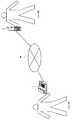
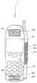
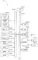
まず、図1乃至図4を参照して、第1の実施の形態に係る固定電話機1の構成について説明する。図1は、固定電話機1及び携帯電話機2についての全体構成図である。図2は、固定電話機1の構成を示す図である。図3は、携帯電話機2の構成を示す図である。図4は、固定電話機1(携帯電話機2)の電気的構成を示すブロック図である。 First, the configuration of the fixed
図1に示すように、固定式の有線通信可能な電話機である固定電話機1と、携帯用の無線通信可能な電話機である携帯電話機2とは、それぞれ電話回線90に接続されて、相互に各種信号の送受信が可能である。固定電話機1の利用者(以下、ユーザAと呼ぶ)と携帯電話機2の通話相手(以下、ユーザBと呼ぶ)とは、電話回線90を介して相互に音声通話が可能である。 As shown in FIG. 1, a
図2及び図4に示すように、固定電話機1は、受話器1aと本体部1bとから構成される。受話器1aには、ユーザBからの発せられた音声が出力されるスピーカ151と、ユーザAが発した音声が入力されるマイク152が設けられ、ユーザAはこの受話器1aを握り持ち、スピーカ151を耳に、マイク152を口に当てた状態で、ユーザBとの会話を行う。 As shown in FIGS. 2 and 4, the fixed
受話器1aには、ユーザAの体温を計測する体温センサ182と、発汗状態を計測するための発汗センサ183と、心拍数を計測するための心拍数センサ184とが設けられる。各センサの読取部は受話器1aの側面部表面に設けられ、ユーザAが受話器1aを握り持つ状態でユーザAの掌に接触して、適切にユーザAを計測可能な状態に設けられる。そのため、固定電話機1では通話中のユーザAはセンサにより計測される状態に保持される。 The
通話中のユーザAが口をあてるマイク152の近傍には、発光部192及び振動部193が設けられる。発光部192は、例えばRGB発光ダイオード素子であり、その光量,点滅時間間隔,発光色の発光態様が制御されて、ユーザBの推論情報をユーザAに通知する。なお、発光部192は、通話中のユーザAの視界内に入り、その発光が障害物によって遮断されない位置であれば、受話器1aのいずれの位置に設けられてもよい。 A
振動部193は、例えば電動バイブレータであり、振動の強さ,振動の速さ,振動時間間隔の振動態様が制御されて、ユーザBの推論情報をユーザAに通知する。なお、振動部193は、通話中のユーザAが振動部193による振動動作を体感できる位置であれば、受話器1aのいずれの位置に設けられてもよい。 The
通話中のユーザAが耳をあてるスピーカ151の近傍には、発熱部194が設けられる。発熱部194は、例えばペルチェ素子であり、発熱温度,発熱範囲,発熱面積の発熱態様が制御されて、ユーザBの推論情報をユーザAに通知する。なお、発熱部194は、通話中のユーザAが感温可能な位置であれば、受話器1aのいずれの位置に設けられてもよい。特に発熱部194の温度変化の速度によっては、把持部では反射的に受話器を手放してしまう可能性があるため、把持部以外の位置に設けることで、受話器の放り出しを防止する設計にしてもよい。 A
なお、振動部193をスピーカ151から大きく離間したマイク152の近傍に設けているのは、振動部193による振動が、スピーカ151からの音声に悪影響を及ぼすことを回避するためである。また、受話器1aの側面に設けられたセンサのうち、体温センサ182を最も背面方向に設けたのは、発熱部194の影響を低減するためである。このように、好適には、発光部192,振動部193,発熱部194などの情報提示手段が、お互いに干渉することがなく、また、各センサや他の構成に影響を及ぼすことがないように、各情報提示手段を配置する。 The reason why the
本体部1bには、各種のボタンやスイッチを備えた入力パネル181と、ユーザAに対して各種情報を表示するための表示部(LED)191とが設けられる。図示しないが、入力パネル181には、ユーザAがユーザBの電話番号を入力するためのダイヤルボタンや、固定電話機1の機能や動作に関する諸設定を行うための設定確認ボタンや、みずからの意思を意図的に入力するために、ユーザA自身がオン・オフしてスイッチ情報を入力するための意思伝達スイッチとが、少なくとも設けられる。 The main body 1b is provided with an
図3及び図4に示すように、携帯電話機2には、スピーカ251,マイク252,入力パネル281,体温センサ282,発汗センサ283,心拍数センサ284,表示部(LED)291,発光部292,振動部293,発熱部294が設けられ、これらはそれぞれ固定電話機1(図2)におけるスピーカ151,マイク152,入力パネル181,体温センサ182,発汗センサ183,心拍数センサ184,表示部191,発光部192,振動部193,発熱部194に相当する。固定電話機1は受話器1aと本体部1bとが分離して構成されているのに対し、上記の構成が一体の携帯電話機2に具備されている点で異なるが、各構成の機能や動作は基本的に同じである。 As shown in FIGS. 3 and 4, the
図4に示すように、固定電話機1(携帯電話機2)には、固定電話機1(携帯電話機2)の制御を司るCPU110(CPU210)が設けられている。このCPU110(CPU210)には、バス115(バス215)を介し、CPU110(CPU210)が実行するBIOS等のプログラムを記憶したROM120(ROM220)と、データを一時的に記憶するRAM130(RAM230)とが接続されている。また、現在日時や時間間隔をカウントするための計時装置190(計時装置290)が、バス115(バス215)を介してCPU110(CPU210)に接続されている。計時装置190(計時装置290)は、時計機能を備えたICチップであるが、インターネットや無線によって日時を取得するように構成してもよい。 As shown in FIG. 4, the fixed telephone 1 (mobile telephone 2) is provided with a CPU 110 (CPU 210) that controls the fixed telephone 1 (mobile telephone 2). The CPU 110 (CPU 210) includes a ROM 120 (ROM 220) that stores programs such as BIOS executed by the CPU 110 (CPU 210) and a RAM 130 (RAM 230) that temporarily stores data via the bus 115 (bus 215). It is connected. In addition, a timer device 190 (timer device 290) for counting the current date and time and time interval is connected to the CPU 110 (CPU 210) via the bus 115 (bus 215). The time measuring device 190 (time measuring device 290) is an IC chip having a clock function, but may be configured to acquire the date and time via the Internet or wirelessly.
また、各種機器からの入力及び出力の検知を行う入出力I/O180(入出力I/O280)が、バス115(バス215)を介してCPU110(CPU210)に接続されており、この入出力I/O180(入出力I/O280)には、入力パネル181(入力パネル281),体温センサ182(体温センサ282),発汗センサ183(発汗センサ283),心拍数センサ184(心拍数センサ284)が接続されている。なお、本実施の形態では、体温センサ182(体温センサ282)では計測値として0〜50℃が計測され、発汗センサ183(発汗センサ283)では計測値として0〜100%RHが計測され、心拍数センサ184(心拍数センサ284)では計測値として0〜200拍が計測されるものとする。これらの各センサから計測される情報が、本発明の「計測値」に相当する。 An input / output I / O 180 (input / output I / O 280) that detects input and output from various devices is connected to the CPU 110 (CPU 210) via the bus 115 (bus 215). / O180 (input / output I / O280) includes an input panel 181 (input panel 281), a body temperature sensor 182 (body temperature sensor 282), a sweat sensor 183 (sweat sensor 283), and a heart rate sensor 184 (heart rate sensor 284). It is connected. In the present embodiment, the body temperature sensor 182 (body temperature sensor 282)
各センサは、固定電話機1(携帯電話機2)が他の端末との通話状態になると、自動的に定期的な計測を実行するように制御される。そして、RAM130(RAM230)に設けられたセンサ毎の計測値記憶エリア(図示外)に、各センサの計測値が入出力I/O180(入出力I/O280)を介して保存され、この計測値記憶エリアが参照されて最新の計測値が取得される。なお、各センサの計測値が各センサ内部の所定の記憶エリアに保存されて、入出力I/O180(入出力I/O280)を介してこの所定の記憶エリアから最新の計測値が取得されてもよい。 Each sensor is controlled to automatically perform periodic measurement when the fixed telephone 1 (mobile telephone 2) is in a call state with another terminal. And the measured value of each sensor is preserve | saved via the input / output I / O180 (input / output I / O280) in the measured value storage area (not shown) for every sensor provided in RAM130 (RAM230), and this measured value The storage area is referred to obtain the latest measured value. The measured value of each sensor is stored in a predetermined storage area inside each sensor, and the latest measured value is acquired from this predetermined storage area via the input / output I / O 180 (input / output I / O 280). Also good.
また、入力パネル181(入力パネル281)には、意思伝達スイッチが設けられる。ユーザはみずからの意思を意図的に固定電話機1(携帯電話機2)に伝達するために、意思伝達スイッチをオン又はオフする。例えば、本実施の形態では、固定電話機1(携帯電話機2)は各ユーザの「感動」について推論するものであるから、各ユーザは通話中に感動した場合には意思伝達スイッチをオンしてスイッチ情報「ON」を入力し、感動しない場合には意思伝達スイッチをオンせずに(オフして)スイッチ情報「OFF」を入力する。 The input panel 181 (input panel 281) is provided with a intention transmission switch. The user turns on or off the intention transmission switch in order to intentionally transmit his intention to the fixed telephone 1 (mobile telephone 2). For example, in the present embodiment, the fixed telephone 1 (mobile phone 2) infers about the “feeling” of each user, so that when each user is impressed during a call, the communication switch is turned on to switch When the information “ON” is input and the user is not impressed, the switch information “OFF” is input without turning on (turning off) the intention transmission switch.
そして、第1の実施の形態の固定電話機1(携帯電話機2)では、各センサからのセンサ情報と、意思伝達スイッチからのスイッチ情報とに基づいて、各ユーザが通話中にどのような感情や意識などを生じたかを示す推論情報が作成される。なお、本実施の形態の固定電話機1(携帯電話機2)で実行されるモジュールの一つとして、推論情報作成プログラムが実行される。推論情報作成プログラムは、あらかじめROM120(ROM220)上のプログラム記憶エリア(図示外)に記憶されている。 Then, in the fixed telephone 1 (mobile phone 2) of the first embodiment, what feelings and the feelings each user has during a call based on the sensor information from each sensor and the switch information from the intention transmission switch. Inference information indicating whether consciousness or the like has occurred is created. Note that an inference information creation program is executed as one of the modules executed by the fixed telephone 1 (mobile phone 2) of the present embodiment. The inference information creation program is stored in advance in a program storage area (not shown) on the ROM 120 (ROM 220).
なお、各センサから計測された情報に基づいて、各ユーザの意識や感情を推論する機能を具備するのが推論エンジンである。推論エンジンには、推論手法や設定条件が定義されており、この定義内容に従って各センサからの計測値に基づいて利用者の意識等を推論するためのプログラムであり、CPU110(CPU210)により実行される。本実施の形態では、複数の推論エンジンが推論情報作成プログラムの一部として、ROM120(ROM220)に記憶され、各ユーザは任意の推論エンジンを選択可能である。 An inference engine has a function of inferring the consciousness and emotion of each user based on information measured from each sensor. The inference engine defines inference methods and setting conditions, and is a program for inferring the user's consciousness and the like based on the measurement values from each sensor in accordance with the definition contents, and is executed by the CPU 110 (CPU 210). The In this embodiment, a plurality of inference engines are stored in the ROM 120 (ROM 220) as a part of the inference information creation program, and each user can select any inference engine.
また、外部の電話回線90を介して、他ユーザの音声信号及び推論情報に関する信号(以下、推論情報信号)を受信したり、各ユーザの音声信号及び推論情報信号を他ユーザに送信するための通信部140(240)と、他ユーザの音声信号を音声に復調したり、各ユーザの音声を音声信号に変調したりする他、他ユーザの推論情報信号を推論情報に復調したり、各ユーザの推論情報を推論情報信号に変調したりする復変調部150(復変調部250)と、他ユーザの音声を出力するスピーカ151(スピーカ251)及び各ユーザの音声を入力するマイク152(252)とが設けられる。なお、本実施の形態では、固定電話機1における通信部140は有線によって、携帯電話機2における通信部240は無線によって、それぞれ電話回線90に接続する機能を有し、各ユーザと他ユーザとの間でやり取りされる音声信号及び推論情報信号は、パケット符号化されているものとする。 In addition, for receiving signals related to other users' voice signals and inference information (hereinafter referred to as inference information signals) via the
そして、第1の実施の形態の固定電話機1(携帯電話機2)では、音声信号及び推論情報信号が送受信されて、各ユーザと他ユーザとの間で音声による通話がなされることに加え、他ユーザの推論情報に基づいて固定電話機1(携帯電話機2)の動作が制御されて、他ユーザの推論情報が各ユーザに対して通知される。なお、本実施の形態の固定電話機1(携帯電話機2)で実行されるモジュールの一つとして、情報提示プログラムが実行されることで情報提示態様が特定されて、その各情報提示態様による動作が制御される。情報提示プログラムは、あらかじめROM120(ROM220)上のプログラム記憶エリア(図示外)に記憶されている。また、発光部192(292),振動部193(293),発熱部194(294)の情報提示手段が設けられ、これらの一部又は全部における動作が制御されて、各種情報提示態様が実行される。 In the fixed telephone 1 (mobile phone 2) of the first embodiment, voice signals and inference information signals are transmitted and received, and voice calls are made between each user and other users. The operation of the fixed telephone 1 (mobile phone 2) is controlled based on the inference information of the user, and the inference information of other users is notified to each user. As one of the modules executed by the fixed telephone 1 (mobile phone 2) of the present embodiment, the information presentation mode is specified by executing the information presentation program, and the operation according to each information presentation mode is performed. Be controlled. The information presentation program is stored in advance in a program storage area (not shown) on the ROM 120 (ROM 220). In addition, information presenting means for the light emitting section 192 (292), the vibrating section 193 (293), and the heat generating section 194 (294) are provided, and the operation of some or all of them is controlled to execute various information presenting modes. The
以上のように、固定電話機1及び携帯電話機2は基本的な構成が共通するが、本実施の形態では、固定電話機1のユーザAと携帯電話機2のユーザBとが通話するとともに、携帯電話機2においてユーザBの推論情報が作成される一方(推論情報作成処理)、固定電話機1ではユーザBの推論情報に基づいて、各種情報提示態様によってユーザBの感情や意識などがユーザAに対して通知される(情報提示処理)。 As described above, the fixed
以下では、携帯電話機2における「推論情報作成処理」及び固定電話機1における「情報提示処理」について説明するが、同時に並行して通常の電話による通話処理が実行される。すなわち、携帯電話機2では「推論情報作成処理」と同時並行して、マイク252から入力されたユーザBの音声が復変調部250において音声信号に変調されて、通信部240により固定電話機1に送信される処理が実行される。また、固定電話機1では「情報提示処理」と同時並行して、通信部140により受信された音声信号からユーザBの音声が復調されて、スピーカ151からユーザAに対して出力される処理が実行される。なお、本実施の形態では、固定電話機1と携帯電話機2との間では、音声信号がパケット符号化されて送受信されるものとする。 In the following, “inference information creation processing” in the
まず、本発明の携帯電話機2での「推論情報作成処理」の処理の流れを、図5乃至図11を参照して説明する。図5は、推論情報作成処理のメインフローチャートである。図5は、推論情報作成処理のメインフローチャートである。図6は、推論エンジン初期化処理(S1)の詳細を示すフローチャートである。図7は、推論データ作成処理(S4)の詳細を示すフローチャートである。図8は、推論実行処理(S164)の詳細を示すフローチャートである。図9は、推論定義テーブル13のデータ構成を示す図である。図10は、推論情報出力処理(S11)の詳細を示すフローチャートである。図11は、推論情報10のデータ構成を示す図である。 First, the process flow of the “inference information creation process” in the
推論情報作成処理のメインフローチャート(図5)は、ユーザBが携帯電話機2を用いて通話中に実行される。すなわち、携帯電話機2において、電話の着信又は発信がなされると推論情報作成処理が開始されて、通話中はその処理が継続して実行され、通話が終了するとその処理が終了される。 The main flowchart (FIG. 5) of the inference information creation process is executed while the user B uses the
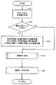
図5に示すように、推論情報作成処理では、まず推論エンジン初期化処理(S1)が実行される。推論エンジン初期化処理は、後述の推論データ作成処理の際に参照される各センサ毎の基準値を初期化する処理である。 As shown in FIG. 5, in the inference information creation process, an inference engine initialization process (S1) is first executed. The inference engine initialization process is a process for initializing a reference value for each sensor that is referred to in the later-described inference data creation process.
図6に示すように、推論エンジン初期化処理(S1)では、変数ST,変数SH,変数SMにそれぞれ「0」が代入され(S101)、変数Tに「3」が代入される(S102)。そして、各センサから計測値が取得される(S103)。すなわち、体温センサ282,発汗センサ283,心拍数センサ284によって、ユーザBの体温,発汗,心拍数が計測されて、これらセンサから計測値が各々取得される。
各センサから取得された体温,発汗,心拍数の各計測値が、それぞれ変数ST,変数SH,変数SMに加算される(S104)。なお、S103による計測値の取得が1回目であれば、S102により変数ST,変数SH,変数SMには「0」が代入されているため、S103により取得された体温,発汗,心拍数の各計測値が、そのまま変数ST,変数SH,変数SMに代入される。As shown in FIG. 6, in the inference engine initialization process (S1), “0” is assigned to the variable ST, variable SH, and variable SM (S101), and “3” is assigned to the variable T (S102). . And a measured value is acquired from each sensor (S103). That is, the body temperature, sweating, and heart rate of the user B are measured by the
The measured values of body temperature, sweating, and heart rate acquired from each sensor are added to the variable ST, variable SH, and variable SM, respectively (S104). If the measurement value is acquired for the first time in S103, since “0” is substituted for the variable ST, variable SH, and variable SM in S102, each of the body temperature, sweating, and heart rate acquired in S103 is obtained. The measured value is directly substituted into the variable ST, variable SH, and variable SM.
そして、変数Tが「1」減算されて(S105)、Tが「0」でなければ(S106:NO)、S103に戻り、再び各センサによる計測値が取得される。このように、S102で変数Tに設定された回数(ここでは3回)に至るまで、S103の計測値の取得が実行されて、S103〜S106の処理が繰り返される。その結果、Tが「0」であれば(S106:YES)、変数ST,変数SH,変数SMには、変数Tに設定された回数分の計測値の合計値が記憶される。 Then, the variable T is decremented by “1” (S105), and if T is not “0” (S106: NO), the process returns to S103, and the measurement values obtained by the sensors are acquired again. In this way, until the number of times set to the variable T in S102 (here, 3 times) is reached, the measurement value acquisition in S103 is executed, and the processing in S103 to S106 is repeated. As a result, if T is “0” (S106: YES), the variable ST, variable SH, and variable SM store the total value of the measurement values for the number of times set in the variable T.
変数ST,変数SH,変数SMは、変数Tに設定された値である「3」で各々除算されて、それぞれ変数CT,変数CH,変数CMに代入される(S107)。すなわち、各センサ毎の計測値の合計値を、その計測回数で除算することで、各センサの1回の計測値の平均値(=平常時の基準値)が取得される。 The variable ST, variable SH, and variable SM are respectively divided by “3”, which is the value set in the variable T, and assigned to the variable CT, variable CH, and variable CM, respectively (S107). That is, by dividing the total value of the measured values for each sensor by the number of times of measurement, an average value (= normal reference value) of one measured value of each sensor is obtained.
変数CTは体温センサ282の基準値であり、変数CHは発汗センサ283の基準値であり、変数CMは心拍数センサ284の基準値である。これらの各センサの基準値は、RAM230に設けられた基準値エリア(図示外)に保存される。 The variable CT is a reference value for the
図5に戻り、推論エンジンの選択が実行される(S2)。携帯電話機2では複数の推論エンジンから任意のものを選択可能であり、各推論エンジンによって推論データを作成するための処理内容が異なる。各推論エンジンはROM220のプログラム記憶エリア(図示外)に記憶されており、S2において後述の推論データ作成処理を実行する推論エンジンが決定される。 Returning to FIG. 5, the selection of the inference engine is executed (S2). The
推論エンジンの選択(S2)は、ユーザBが入力パネル281の推論エンジン選択スイッチ(図示せず)から任意のものを選択することにより実行される。また、携帯電話機2において実行される推論エンジンがあらかじめ設定されている場合は、その設定済みの推論エンジンが自動的に読込まれて選択される。ユーザBによる推論エンジンの選択がない場合は、自動的にデフォルトの推論エンジンが設定される。 The selection of the inference engine (S2) is executed by the user B selecting an arbitrary one from an inference engine selection switch (not shown) on the
次に、携帯電話機2において通話が終了したか否かが判定される(S3)。携帯電話機2の電源がOFFされたり、切断ボタンが押下されたり、電話回線との接続が終了した場合などは、通話が終了したと判定される。通話が終了したと判定された場合(S3:YES)、推論情報作成処理が終了される。 Next, it is determined whether or not the call is ended in the mobile phone 2 (S3). When the
一方、通話が終了していないと判定された場合(S3:NO)、S2で選択された推論エンジンに従って、センサから計測された情報に基づいて推論データを作成する推論データ作成処理(S4)が実行される。先述のように推論データ作成処理での処理内容は、推論エンジンによって様々なものが可能であるが、本実施の形態では、推論定義テーブル13(図9参照)が参照されて推論データを作成する推論エンジンによる処理の一例を示す。 On the other hand, when it is determined that the call has not ended (S3: NO), an inference data creation process (S4) for creating inference data based on information measured from the sensor according to the inference engine selected in S2 is performed. Executed. As described above, the processing contents in the inference data creation process can be various depending on the inference engine. In this embodiment, the inference data is created by referring to the inference definition table 13 (see FIG. 9). An example of processing by the inference engine is shown.
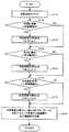
図7に示すように、推論データ作成処理(S4)では、体温センサ282,発汗センサ283,心拍数センサ284の各センサで計測されたユーザBの体温,発汗,心拍数の計測値が、各々取得される(S161)。次に、意思伝達スイッチが「ON」か否かが判定される(S162)。意思伝達スイッチが「ON」であれば(S162:YES)、あらかじめ定められた補正値によってS161で取得された各センサ計測値が補正される(S163)。補正値は各センサごとにあらかじめ定められており、この補正処理は各センサの計測値ごとに実行される。例えば、体温計測値「36℃」に対しては体温補正値「1℃」が加算されて体温計測値「37℃」に補正され、同様に、発汗計測値は発汗補正値により補正され、心拍数計測値は心拍数補正値により補正される。そして、この補正後の各センサ計測値に基づいて、推論実行処理が実行される(S164)。一方、意思伝達スイッチが「OFF」であれば(S162:NO)、S161で取得された各センサ計測値に基づいて、後述の推論実行処理が実行される(S164)。そして、S164で取得された推論種別及び推論値を含む推論データが作成される(S165)。 As shown in FIG. 7, in the inference data creation process (S4), the measured values of the body temperature, sweating, and heart rate of the user B measured by the
図8に示すように、推論実行処理(S164)では、各センサからの計測値の状態変化を示すフラグである状態変数がクリアされる(S171)。本実施の形態では、体温センサ282が計測する体温についての第2bit、発汗センサ283が計測する発汗についての第1bit、心拍数センサ284が計測する心拍数についての第0bit、の3つのビットを状態変数として有している。そして、RAM230の基準値エリア(図示外)を参照して、S107(図6参照)で算出された各センサの基準値に基づいて、各センサからの計測値の変化を判定する。 As shown in FIG. 8, in the inference execution process (S164), a state variable which is a flag indicating a state change of a measurement value from each sensor is cleared (S171). In the present embodiment, three bits of the second bit for the body temperature measured by the
最初に、体温センサ282から取得された体温計測値と、体温に関する基準値(体温閾値)とが比較される(S172)。基準値(閾値)は、RAM230の基準値エリア(図示外)に保存された値である。その結果、体温計測値が体温閾値よりも大きければ(S2172:YES)、第2bitが「UP」にセットされる(S173)。一方、体温計測値が体温閾値よりも大きくない場合(S172:NO)、そのまま次のステップ(S174)へ進む。同様に、発汗センサ283から取得された発汗計測値と、発汗に関する基準値(発汗閾値)とが比較され(S174)、その結果、発汗計測値が発汗閾値よりも大きければ(S174:YES)、第1bitが「UP」にセットされる(S175)。一方、発汗計測値が発汗閾値よりも大きくない場合(S174:NO)、そのまま次のステップ(S176)へ進む。また、心拍数センサ284から取得された心拍数計測値も、心拍数に関する基準値(心拍数閾値)と比較され(S176)、その結果、心拍数計測値が心拍数閾値よりも大きければ(S176:YES)、第0bitが「UP」にセットされる(S177)。一方、心拍数計測値が心拍数閾値よりも大きくない場合(S176:NO)、そのまま次のステップ(S178)へ進む。 First, the body temperature measurement value acquired from the
その後、状態変数の第2bit,第1bit,第0bitまでのパターンに対応する推論種別及び推論値が、推論定義テーブル13から取得される(S178)。図9に示すように、推論定義テーブル13は、推論の種別を示す推論種別13aと、各センサからの計測値の変化状態を示すセンサ状態13bと、ユーザBの推論の強弱を数値で示す推論値13cとをデータ項目として具備している。そして、各々のデータ項目の対応を、テーブル形式で定義している。先述のように、本実施の形態ではユーザBの「感動」に関する推論データが作成されるから、参照される推論定義テーブル13も「感動」に関するものである。よって、その推論種別13aは「感動」に関する種別が定義されており、「感動」の強弱によって「大興奮」から「無感動(平常)」までの複数の種別が存在している。また、その「感動」の強弱を数値で表した推論値13cが定義され、例えば、推論種別13aが「大興奮」であれば、その推論値13cは最大値の「100」である。なお、図9に示す推論定義テーブル13は「感動」に関するものであるから、推論値13cは感動度(E)とも表示される。そして、S178では、S172〜S177によりセットされた状態変数によってセンサ状態13bが特定されるから、このセンサ状態13bに対応する推論種別13aや推論値13cが取得される。 Thereafter, the inference type and the inference value corresponding to the patterns of the second bit, the first bit, and the 0th bit of the state variable are acquired from the inference definition table 13 (S178). As shown in FIG. 9, the inference definition table 13 includes an
以上、S2において選択された推論エンジンがCPU210により実行されて、推論データ作成処理(S4)が実行され、推論データが作成される。このように、複数の推論エンジンを設けて、ユーザBが任意の推論エンジンを選択できるため、携帯電話機2の利用状況や利用環境等に応じて、最適な推論エンジンによって推論データを作成でき、また、より正確にユーザBに関する推論データを作成することができる。 As described above, the inference engine selected in S2 is executed by the
図5に戻り、推論データ作成処理(S4)で作成された推論データを出力する推論情報出力処理(S11)が実行される。図10で示すように、推論データに基づいて推論情報が作成される(S301)。図11に示すように、推論情報10には、少なくとも推論値10a,推論種別10bが含まれる。推論値10aと推論種別10bは、推論データに含まれる推論値13c及び推論種別13aに各々対応している。なお、推論情報10に、現在日時を示す日時データや推論エンジンのID番号などの関連情報が含まれてもよい。S301で作成された推論情報10は、復変調部250において電話回線90に送信可能な信号である推論情報信号に変調及びパケット符号化されて(S302)、通信部240により固定電話機1にパケット送信される(S303)。 Returning to FIG. 5, the inference information output process (S11) for outputting the inference data created in the inference data creation process (S4) is executed. As shown in FIG. 10, inference information is created based on the inference data (S301). As shown in FIG. 11, the
その後、図5に戻り、所定時間が経過したか否かが判定される(S12)。この所定時間は、あらかじめ計時装置290にセットされている時間であり、S12では計時装置290を参照して、所定時間の経過が判定される。計時装置290にセットされる所定時間は、ユーザB又は設計者によって任意の時間を設定可能である。 Thereafter, returning to FIG. 5, it is determined whether or not a predetermined time has passed (S12). This predetermined time is a time set in advance in the
所定時間が経過していなければ(S12:NO)、S12で待ち状態となり、所定時間が経過するまで、このループ処理が繰り返される。一方、所定時間が経過した場合(S12:YES)、S3へ戻り、通話が終了していなければ(S3:NO)、推論データ作成処理(S4)が実行されて推論データが作成され、さらに推論情報10が出力される(S11)。すなわち、携帯電話機2でユーザBが通話中は、所定時間毎に推論情報10が固定電話機1に送信される処理が繰り返される。 If the predetermined time has not elapsed (S12: NO), the process enters a waiting state in S12, and this loop processing is repeated until the predetermined time has elapsed. On the other hand, if the predetermined time has elapsed (S12: YES), the process returns to S3, and if the call has not ended (S3: NO), the inference data creation process (S4) is executed to create inference data, and
以上、携帯電話機2における「推論情報作成処理」では、各センサからの計測値とユーザBによるスイッチ情報とに基づいて、通話中のユーザBの「感動」状態について正確に推論した推論情報10を作成することができる。そして、この推論情報10が固定電話機1に送信されて、固定電話機1では以下のように、推論情報10の内容がユーザAに通知される。 As described above, in the “inference information creation process” in the
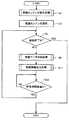
次に、本発明の固定電話機1での「情報提示処理」の処理の流れを、図12乃至図15を参照して説明する。図12は、情報提示処理のメインフローチャートである。図13は、推論情報提示実行処理(S27)の詳細を示すフローチャートである。図14は、情報提示態様特定テーブル17のデータ構成を示す図である。図15は、発熱部194(発熱部294)の具体的構成を説明するための図である。 Next, the flow of the “information presentation process” in the fixed
情報提示処理のメインフローチャート(図12)は、推論情報作成処理(図5)と同様に、ユーザAが固定電話機1を用いて通話中に実行される。すなわち、固定電話機1において、電話の着信又は発信がなされると情報提示処理が開始されて、通話中はその処理が継続して実行され、通話が終了するとその処理が終了される。 The main flowchart (FIG. 12) of the information presentation process is executed during a call using the fixed
図12に示すように、情報提示処理では、通話が終了したか否かが判定される(S21)。固定電話機1において、受話器1aが本体部1bの所定部位に戻されたり、切断ボタンが押下されたり、電話回線との接続が終了した場合などは、通話が終了したと判定される。通話が終了したと判定された場合(S21:YES)、情報提示処理が終了される。 As shown in FIG. 12, in the information presentation process, it is determined whether or not the telephone call is finished (S21). In the
通話が終了していないと判定された場合(S21:NO)、携帯電話機2から送信されたパケットが、通信部140により電話回線90から受信される(S22)。そして、S22で受信されたパケットの種類が音声信号か否かが判定される(S23)。パケットが音声信号であれば(S23:YES)、復変調部150により音声信号がユーザBの音声に復号されて(S24)、スピーカ151から出力される(S25)。一方、パケットが音声信号でなければ(S23:NO)、パケットは推論情報信号であるため、復変調部150により推論情報信号がユーザBの推論情報10(図11参照)に復号され(S26)、後述の推論情報提示実行処理(S27)が実行される。 When it is determined that the call has not ended (S21: NO), the packet transmitted from the
図13に示すように、推論情報提示実行処理(S27)では、S26で復号された推論情報10から推論値10aである感動度(E)が取得される(S401)。そして、この感動度(E)に基づいて情報提示態様特定テーブル17が参照されて、ユーザAに対して実行すべき情報提示態様が特定される(S402)。 As shown in FIG. 13, in the inference information presentation execution process (S27), the sensitivity (E) that is the
図14に示すように、情報提示態様特定テーブル17は、推論値17aと、発熱部194における発熱温度,発熱範囲,発熱面積などを定義した発熱態様17bと、振動部193における振動の強さ,振動の速さ,振動時間間隔などを定義した振動態様17cと、発光部192における光量,点滅時間間隔,発光色などを定義した発光態様17dとをデータ項目として具備する。そして、各々のデータ項目の対応を、テーブル形式で定義する。先述のように、本実施の形態ではユーザBの「感動」に関する推論情報10が作成されるから、参照される情報提示態様特定テーブル17も「感動」に関するものである。 As shown in FIG. 14, the information presentation mode specification table 17 includes an
本実施の形態の情報提示態様特定テーブル17では、推論値17aである感動度(E)が高い値を示すほど、発熱態様17bとしてより広い面積を発熱し、振動態様17cとしてより短い周期で振動し、発光態様17dとしてより明るい色で発光して、ユーザAにより強い刺激や印象を与えるような情報提示態様が定義される。例えば、感動度(E)が最大値「100」であれば、発熱態様17b「全面」,振動態様17c「連続」,発光態様17d「白」が情報提示態様として特定される一方、感動度(E)が最小値「0」であれば、発熱態様17b「なし」,振動態様17c「なし」,発光態様17d「なし」が情報提示態様として特定される。 In the information presentation mode specification table 17 of the present embodiment, the higher the sensitivity (E), which is the
S402でユーザBの推論情報10に対応する情報提示態様が特定されると、発熱態様17bに基づいて発熱部194が動作するように制御される(S403)。図15に示すように、発熱部194を発熱素子を同心円状に重ねた構成とすれば、その発熱面積や発熱温度などを電気的に容易に制御可能である。好適には、発熱部194は、通話中のユーザBの耳が当てられるスピーカ151の中心部位から、同心円状に発熱面積が変化するように制御される。 When the information presentation mode corresponding to the
同様に、振動態様17cに基づいて振動部193が動作するように制御され(S404)、発光態様17dに基づいて発光部192が動作するように制御される(S405)。発光態様17d及び発光部192の動作制御も、公知の技術により電気的に制御される。 Similarly, the
図12に戻り、S25又はS27の後、S21へ戻り、通話が終了していなければ(S21:NO)、さらにパケットが受信されて(S22)、音声出力(S25)又は推論情報提示実行処理(S27)が実行される。すなわち、固定電話機1でユーザAが通話中は、ユーザBについての音声出力と推論情報提示が継続的に繰り返して実行される。 Returning to FIG. 12, after S25 or S27, the process returns to S21. If the call is not finished (S21: NO), a packet is further received (S22), and voice output (S25) or inference information presentation execution processing ( S27) is executed. That is, while user A is talking on the fixed
以上、固定電話機1における「情報提示処理」では、スピーカ151からユーザBの音声を出力するのみならず、ユーザBの推論情報10に対応する情報提示態様によって、通話中のユーザBの「感動」状態を、ユーザAに対して確実に通知することができる。特に、発熱部194,振動部193,発光部192による情報提示態様によって、ユーザAは受話器1aを用いて通話しながらでも、ユーザBの「感動」状態を正確に把握できる。 As described above, in the “information presentation process” in the fixed
ところで、携帯電話機2を送信側、固定電話機1を受信側として説明したが、固定電話機1と携帯電話機2とは基本的に同一構成及び同一機能(図4参照)を有し、また電話通話ではお互いに各ユーザの音声が入出力される。よって、固定電話機1を送信側、携帯電話機2を受信側として機能させることも当然可能である。その場合、固定電話機1及び携帯電話機2の双方で、推論情報作成処理(図5)及び情報提示処理(図12)が実行されて、固定電話機1と携帯電話機2の通話中は、双方で音声の入力と推論情報10の作成が実行されて、相互に音声及び推論情報10が送受信され、かつ双方で音声の出力と推論情報10に基づいた情報提示処理とが実行される。よって、固定電話機1及び携帯電話機2の各ユーザが他ユーザの「感動」状態を把握しながら、電話通話することができる。 The
以上、第1の実施の形態の固定電話機1及び携帯電話機2によれば、携帯電話機2(固定電話機1)において、通話中のユーザB(ユーザA)の「感動」状態について正確に推論した推論情報10を作成することができ、固定電話機1(携帯電話機2)において、ユーザB(ユーザA)の音声を出力するのみならず、通話中のユーザB(ユーザA)の「感動」状態を、ユーザA(ユーザB)に対して確実に通知することができる。 As described above, according to the fixed
次に、本発明の第2の実施の形態を図面を参照して説明する。第2の実施の形態に係る音声通信装置も、利用者と通話相手とが通話とするための固定電話機又は携帯電話機であり、基本的な構成は第1の実施の形態と同じである。しかし、第1の実施の形態では推論情報10が送受信されるのに対し、本実施の形態では、携帯電話機2から固定電話機1へセンサからの計測値及びユーザBのスイッチ情報が送信されて、固定電話機1でユーザBの推論情報が作成される。なお、本実施の形態において、通話相手に関する情報とは、センサから計測された情報及びユーザBが入力した情報である。 Next, a second embodiment of the present invention will be described with reference to the drawings. The voice communication apparatus according to the second embodiment is also a fixed telephone or a mobile phone for making a call between the user and the other party, and the basic configuration is the same as that of the first embodiment. However, while the
本実施の形態では、携帯電話機2において、固定電話機1との通話中は、体温センサ282,発汗センサ283,心拍数センサ284の各センサで計測されたユーザBの体温,発汗,心拍数の計測値が各々取得されて、復変調部250により変調化、パケット符号化されて、通信部240により固定電話機1に送信される。同様に、ユーザBが意思伝達スイッチをONしたスイッチ情報も、変調化、パケット符号化されて送信される。この処理も、通話中に、あらかじめ定められた期間ごとに定期的に繰り返し実行される。 In the present embodiment, the
一方、固定電話機1では、携帯電話機2との通話中は、推論情報作成処理(図5)が実行される。ただし、「各センサからの計測値の取得」(図6のS103,図7のS161)では、通信部140により携帯電話機2から受信され、復変調部150により復号化された各センサからの計測値が取得される。同様に、「意思伝達スイッチ=ONか?」(図7のS162)の判定も、携帯電話機2から受信したスイッチ情報に基づいて判定される。 On the other hand, in the fixed
以上の処理により、第1の実施の形態と同様のユーザBに関する推論情報10(図11参照)が、固定電話機1において作成される。そして、この推論情報10に基づいて、固定電話機1において情報提示処理(図12)が実行される。なお、携帯電話機2においても、本実施の形態の固定電話機1と同様にできることはいうまでもない。 Through the above processing, the inference information 10 (see FIG. 11) relating to the user B similar to that in the first embodiment is created in the fixed
以上、第2の実施の形態の固定電話機1及び携帯電話機2によれば、携帯電話機2(固定電話機1)から送信されたセンサからの計測値及びスイッチ情報を受信して、固定電話機1(携帯電話機2)において、通話中のユーザB(ユーザA)の「感動」状態について正確に推論した推論情報10を作成し、ユーザB(ユーザA)の音声を出力するのみならず、通話中のユーザB(ユーザA)の「感動」状態を、ユーザA(ユーザB)に対して確実に通知することができる。 As described above, according to the fixed
次に、本発明の第3の実施の形態を図面を参照して説明する。図16は、固定電話機1(携帯電話機2)の電気的構成を示す他のブロック図である。第1の実施の形態に係る音声通信装置では、各センサは各ユーザの体温,発汗,心拍数を計測し、情報提示手段は発光,振動,発熱に関する動作を行う。しかしながら、また、各センサ及び情報提示手段は、これらに限定されず、各種のものを適用可能である。 Next, a third embodiment of the present invention will be described with reference to the drawings. FIG. 16 is another block diagram showing the electrical configuration of the fixed telephone 1 (mobile telephone 2). In the voice communication apparatus according to the first embodiment, each sensor measures the body temperature, sweating, and heart rate of each user, and the information presentation unit performs operations related to light emission, vibration, and heat generation. However, each sensor and information presentation means are not limited to these, and various types can be applied.
本実施の形態では、固定電話機1(携帯電話機2)において、各ユーザが受話器1a(携帯電話機2)を握る圧力を計測する圧力センサ185(圧力センサ285)が設けられる。図示しないが、この読取部も、受話器1a(携帯電話機2)の側面部表面に設けられ、各ユーザがこの受話器1a(携帯電話機2)を握り持つ状態で各ユーザの掌に接触して、適切に各ユーザの握力を計測可能な状態に設けられる。なお、圧力センサ185(圧力センサ285)を用いた場合の推論情報作成処理も、基準値や単位は異なるものの、他のセンサ計測値と同様の処理がなされればよい(図5参照)。その他、例えば、各ユーザの振動、脳波、呼吸、加速度、傾き、バイオリズムなどが、各ユーザから計測されるようにしてもよい。 In the present embodiment, a fixed sensor 1 (mobile phone 2) is provided with a pressure sensor 185 (pressure sensor 285) that measures the pressure with which each user grips the
また、図示しないが、通話中の各ユーザが耳をあてるスピーカ151(スピーカ251)の近傍には、電流部195(電流部295)が設けられる。電流部195(電流部295)は、例えば微弱電流を流すことができる素子であり、その電流の強度が制御されて、他ユーザの推論情報を各ユーザに通知する。その情報提示態様も、情報提示態様特定テーブル17(図17参照)に任意に定義可能である。 Although not shown, a current unit 195 (current unit 295) is provided in the vicinity of the speaker 151 (speaker 251) to which each user who is talking is listening. The current unit 195 (current unit 295) is an element that can pass a weak current, for example, and the intensity of the current is controlled to notify the inference information of other users to each user. The information presentation mode can also be arbitrarily defined in the information presentation mode specification table 17 (see FIG. 17).
なお、各センサや入力パネルなどは、固定電話機1(携帯電話機2)に一体として構成されている必要はなく、有効に計測値や入力情報を取得できれば、USBやネットワークなどにより遠隔接続してもよい。また、情報提示手段も、固定電話機1(携帯電話機2)から取り外し可能な構成としてもよいし、独立な構成として各ユーザに具備されて、その動作がリモート制御されるようにしてもよい。また、固定電話機1では、これらの情報提示手段が受話器1aではなく、本体部1bに設けられてもよい。また、発光部192(発光部292)は、表示部191(表示部291)と兼用されてもよい。 Each sensor and input panel do not need to be integrated with the fixed telephone 1 (mobile phone 2), and can be remotely connected via USB or a network as long as measurement values and input information can be acquired effectively. Good. In addition, the information presenting means may be configured to be removable from the fixed telephone 1 (mobile telephone 2), or may be provided to each user as an independent structure, and the operation thereof may be remotely controlled. Moreover, in the fixed
以上、第3の実施の形態の固定電話機1及び携帯電話機2によれば、各ユーザの握力を計測する圧力センサ185(圧力センサ285)や、微弱電流をユーザに与える電流部195(電流部295)を用いても本発明を実現できる。すなわち、各センサや情報提示手段としては各種のものを利用可能であり、また様々な組み合わせで利用可能である。また、固定電話機1と携帯電話機2とで、それぞれ設けられる各センサや情報提示手段が一致する必要はなく、様々な態様で本発明の音声通信装置を実現できる。 As described above, according to the fixed
ところで、上記第1乃至第3の実施の形態において、通信部140(通信部240)が本発明の「送信手段」及び「受信手段」に相当し、復変調部150(復変調部250)及びスピーカ151(スピーカ251)は本発明の受信手段により受信された音声信号にもとづいて、通信相手の音声を出力する「音声出力手段」に相当し、復変調部150(復変調部250)及びマイク152(マイク252)が本発明の「音声入力手段」に相当する。また、発光部192(発光部292),振動部193(振動部293),発熱部194(発熱部294),電流部195(電流部295)が、本発明の「情報提示手段」に相当する。 By the way, in the first to third embodiments, the communication unit 140 (communication unit 240) corresponds to the “transmission unit” and the “reception unit” of the present invention, and the re-modulation unit 150 (re-modulation unit 250) and The speaker 151 (speaker 251) corresponds to “audio output means” for outputting the voice of the communication partner based on the audio signal received by the receiving means of the present invention, and includes a remodulation unit 150 (remodulation unit 250) and a microphone. 152 (microphone 252) corresponds to the “voice input means” of the present invention. Further, the light emitting unit 192 (light emitting unit 292), the vibrating unit 193 (vibrating unit 293), the heat generating unit 194 (heat generating unit 294), and the current unit 195 (current unit 295) correspond to the “information presenting means” of the present invention. .
また、情報提示プログラムを実行して、推論情報提示実行処理(図13)を実行するCPU110(CPU210)が、本発明の「情報提示態様特定手段」及び「情報提示態様動作制御手段」に相当する。詳細には、S401〜S402を実行するCPU110が「情報提示態様特定手段」に相当し、S403〜S405を実行するCPU110が「情報提示態様動作制御手段」に相当する。 Further, the CPU 110 (CPU 210) that executes the information presentation program and executes the inference information presentation execution process (FIG. 13) corresponds to the “information presentation mode specifying unit” and the “information presentation mode operation control unit” of the present invention. . Specifically, the
また、体温センサ182(体温センサ282),発汗センサ183(発汗センサ283),心拍数センサ184(心拍数センサ284),圧力センサ185(圧力センサ285)からの計測値の入力を検知する入出力I/O180(入出力I/O280)が、本発明の「計測値取得手段」に相当する。また、推論情報作成プログラムを実行して、推論情報作成処理(図5)を実行するCPU110(CPU210)が、本発明の「推論情報作成手段」に相当する。入力パネル181(入力パネル281)に設けられた意思伝達スイッチが、本発明の「意思入力手段」に相当し、入出力I/O180(入出力I/O280)が本発明の「意思情報取得手段」に相当する。 Also, input / output for detecting input of measurement values from the body temperature sensor 182 (body temperature sensor 282), the sweat sensor 183 (sweat sensor 283), the heart rate sensor 184 (heart rate sensor 284), and the pressure sensor 185 (pressure sensor 285). The I / O 180 (input / output I / O 280) corresponds to the “measurement value acquisition unit” of the present invention. The CPU 110 (CPU 210) that executes the inference information creation program and executes the inference information creation process (FIG. 5) corresponds to the “inference information creation means” of the present invention. The intention transmission switch provided on the input panel 181 (input panel 281) corresponds to the “intention input means” of the present invention, and the input / output I / O 180 (input / output I / O 280) corresponds to the “intention information acquisition means” of the present invention. Is equivalent to.
なお、本発明は、以上詳述した第1乃至第3の実施の形態に限定されるものではなく、各種の変形が可能なことはいうまでもない。利用者の身につける支持部材の形状としては、把持する受話器形状である必要はなく、頭部に装着するヘッドセット型や耳に装着するイヤホン型、PDA型、ブローチなどのアクセサリ型であってもよい。また、支持部材はスピーカ部を有して耳に当接する構成である必要はなく、骨伝導部を有し肌に当接する構成であってもよい。 In addition, this invention is not limited to the 1st thru | or 3rd embodiment explained in full detail above, It cannot be overemphasized that various deformation | transformation are possible. The shape of the support member worn by the user does not need to be the shape of a handset to be grasped, but is a headset type to be worn on the head, an earphone type to be worn on the ear, a PDA type, a broach, or the like. Also good. Further, the support member does not need to have a configuration in which the speaker portion is in contact with the ear, but may have a configuration in which the bone conduction portion is in contact with the skin.
推論データ作成処理(S4)は図7に示すものに限定されず、推論エンジンの選択(S2)で選択された推論エンジンによって、様々な処理が可能である。図17は補正テーブル14のデータ構成を示す図であり、この補正テーブル14を用いて、次のように処理してもよい。各センサからの計測値に基づいてS164の推論実行処理(図8)を実行して推論種別13a及び推論値13cを取得する。意思伝達スイッチがONされていれば、補正テーブル14を参照して、推論種別13a(14a)及び推論値13c(14b)に対応するスイッチON時補正値14cを取得する。このスイッチON時補正値14cにより、補正後の推論種別14d及び推論値14eを取得する。 The inference data creation process (S4) is not limited to that shown in FIG. 7, and various processes are possible depending on the inference engine selected in the selection of the inference engine (S2). FIG. 17 is a diagram showing the data structure of the correction table 14, and the correction table 14 may be used as follows. Based on the measured value from each sensor, the inference execution process (S164) of S164 is executed to acquire the
また、上記実施の形態では、推論情報10が「感動」について推論される場合を説明しているが、感情,意識,状況の他にも、雰囲気や重要度等のように、事象の文脈や状況の前後関係などを示すものであって、事実や証拠のみでは把握できない抽象的な概念(コンテクストともいう。)について、推論情報10が推論されてもよい。そのため、「悲しみ」,「怒り」,「楽しさ」,「賑やかさ」,「忙しさ」等について推論された推論情報10が作成されてもよい。そして、各推論情報10の推論内容に対応する推論定義テーブル13が設定されればよい。例えば、利用者や通話相手の「悲しみ」に基づいて、推論情報10を作成したい場合は、「悲しみ」に対応する推論定義テーブル13が設定されればよい。 Further, in the above embodiment, the case where the
また、推論定義テーブル13には、あらかじめ任意の推論内容についてのテーブルが利用者又は設計者によって設定されていてもよいし、複数の推論内容の各々に対応する複数のテーブルが推論定義テーブル13にあらかじめ設定されており、推論データ作成処理(図7)において、自動的に最適なテーブルが選択されるようにしてもよい。 In addition, in the inference definition table 13, a table for arbitrary inference contents may be set in advance by the user or the designer, and a plurality of tables corresponding to each of a plurality of inference contents are included in the inference definition table 13. It may be set in advance, and an optimum table may be automatically selected in the inference data creation process (FIG. 7).
また、推論エンジン初期化処理(図6)では、サンプリング値を測定してその平均値を基準値として算定しているが、サンプリング値の時系列データを取得して、その推移の特徴に基づいて基準値を算定するようにしてもよい。また、異常なサンプリング値は除外して基準値を算定するようにしてもよい。また、推論実行処理(図8)での比較処理(S172,S174,S176)では、各センサ毎に変化閾値εを設けておき、閾値を変化閾値εで補正した補正値で、各センサからの計測値との比較を実行してもよい。例えば、変化閾値εを誤差許容範囲として、閾値の5%程度を設定する等である。また、本実施の形態では、各センサからの計測値を閾値と比較して状態変化を判定しているが、各センサからの計測値から所定の基準値を減算して増分値を求めて、この増分値が閾値よりも大か小かを比較して状態変化を判定するようにしてもよい。 In addition, in the inference engine initialization process (FIG. 6), the sampling value is measured and the average value is calculated as the reference value, but the time-series data of the sampling value is acquired and based on the characteristics of the transition The reference value may be calculated. Further, the reference value may be calculated by excluding abnormal sampling values. Further, in the comparison process (S172, S174, S176) in the inference execution process (FIG. 8), a change threshold value ε is provided for each sensor, and the correction value obtained by correcting the threshold value with the change threshold value ε Comparison with the measured value may be performed. For example, about 5% of the threshold is set with the change threshold ε as an allowable error range. Further, in the present embodiment, the state change is determined by comparing the measured value from each sensor with a threshold value, but a predetermined reference value is subtracted from the measured value from each sensor to obtain an increment value, The state change may be determined by comparing whether the increment value is larger or smaller than a threshold value.
本発明の音声通信装置は、固定電話機,携帯電話機,PHS,電話機能付パーソナルコンピュータなど、音声通話が可能な端末機器に適用できる。 The voice communication apparatus of the present invention can be applied to terminal equipment capable of voice calls, such as fixed telephones, mobile phones, PHS, and personal computers with telephone functions.
1 固定電話機
1a 受話器
1b 本体部
2 携帯電話機
10 推論情報
13 推論定義テーブル
14 補正テーブル
17 情報提示態様特定テーブル
90 電話回線
110 CPU
115 バス
120 ROM
130 RAM
140 通信部
150 復変調部
151 スピーカ
152 マイク
180 入出力I/O
181 入力パネル
182 体温センサ
183 発汗センサ
184 心拍数センサ
185 圧力センサ
190 計時装置
191 表示部(LED)
192 発光部
193 振動部
194 発熱部
195 電流部
210 CPU
215 バス
220 ROM
230 RAM
240 通信部
250 復変調部
251 スピーカ
252 マイク
280 入出力I/O
281 入力パネル
282 体温センサ
283 発汗センサ
284 心拍数センサ
285 圧力センサ
290 計時装置
291 表示部(LED)
292 発光部
293 振動部
294 発熱部
295 電流部
1 Fixed telephone
DESCRIPTION OF
115
130 RAM
140
181
192
215
230 RAM
240
281
292
Claims (11)
Translated fromJapaneseネットワークを介して音声信号と通話相手に関する情報とを受信する受信手段と、
前記受信手段を支持し、かつ利用者が身につけることが可能な支持部材と、
利用者が前記支持部材を身につけている状態で、前記受信手段により受信された前記通話相手に関する情報を、利用者に通知可能に提示する情報提示手段とを備えることを特徴とする音声通信装置。A voice communication device that performs voice communication with a call partner,
Receiving means for receiving an audio signal and information on the other party over the network;
A support member that supports the receiving means and can be worn by a user;
An audio communication apparatus comprising: information presenting means for presenting information related to the call partner received by the receiving means so that the user can be notified in a state where the user is wearing the support member .
前記情報提示態様特定手段により特定された前記情報提示態様に基づいて、情報提示動作を制御する情報提示動作制御手段とを備え、
前記情報提示手段は、前記情報提示動作制御手段により制御されて、利用者に対する前記情報提示動作を実行することを特徴とする請求項1に記載の音声通信装置。Analyzing information related to the call partner received by the receiving means, and specifying an information presentation mode specifying means for specifying an information presentation mode of information related to the call partner;
An information presentation operation control means for controlling an information presentation operation based on the information presentation aspect specified by the information presentation aspect specifying means;
The voice communication apparatus according to claim 1, wherein the information presentation unit is controlled by the information presentation operation control unit to execute the information presentation operation for a user.
前記情報提示手段は、光を発し、利用者が前記支持部材を把持している状態で、発した光が目視可能な位置に設けられた発光部であって、
前記情報提示態様特定手段は、前記情報提示態様として、前記発光部における光量,点滅時間間隔,発光色の少なくとも1つを発光態様として特定し、
前記情報提示動作制御手段は、前記発光態様に基づいて、前記発光部における発光動作を制御することを特徴とする請求項2に記載の音声通信装置。The support member is a receiver that a user can hold,
The information presenting means is a light emitting unit provided at a position where the emitted light emits light and the user can grasp the emitted light in a state where the user holds the support member,
The information presentation mode specifying unit specifies, as the information presentation mode, at least one of a light amount, a blinking time interval, and a light emission color in the light emitting unit as a light emission mode,
The voice communication apparatus according to claim 2, wherein the information presentation operation control unit controls a light emission operation in the light emitting unit based on the light emission mode.
前記情報提示手段は、振動し、利用者が前記支持部材を把持している状態で、振動が感知可能な位置に設けられた振動部であって、
前記情報提示態様特定手段は、前記情報提示態様として、前記振動部における振動の強さ,振動の速さ,振動時間間隔の少なくとも1つを振動態様として特定し、
前記情報提示動作制御手段は、前記振動態様に基づいて、前記振動部における振動動作を制御することを特徴とする請求項2に記載の音声通信装置。The support member is a receiver that a user can hold,
The information presenting means is a vibrating portion provided at a position where vibration can be sensed in a state where the user vibrates and the user holds the support member,
The information presentation mode specifying means specifies, as the information presentation mode, at least one of a vibration intensity, a vibration speed, and a vibration time interval in the vibration unit as a vibration mode,
The voice communication apparatus according to claim 2, wherein the information presentation operation control unit controls a vibration operation in the vibration unit based on the vibration mode.
前記情報提示手段は、熱を発し、利用者が前記支持部材を把持している状態で、発した熱が感温可能な位置に設けられた発熱部であって、
前記情報提示態様特定手段は、前記情報提示態様として、前記発熱部における発熱温度,発熱範囲,発熱面積の変化の少なくとも1つを発熱態様として特定し、
前記情報提示動作制御手段は、前記発熱態様に基づいて、前記発熱部における発熱動作を制御することを特徴とする請求項2に記載の音声通信装置。The support member is a receiver that a user can hold,
The information presenting means is a heat generating portion provided at a position where the generated heat can be sensed in a state where the heat is generated and the user is holding the support member,
The information presentation mode specifying means specifies, as the information presentation mode, at least one of a change in heat generation temperature, heat generation range, and heat generation area in the heat generating portion as a heat generation mode,
The voice communication apparatus according to claim 2, wherein the information presentation operation control unit controls a heat generation operation in the heat generation unit based on the heat generation mode.
前記情報提示態様特定手段は、発光部、振動部、発熱部の一部又は全部における情報提示動作を組み合わせた情報提示態様を特定し、
前記情報提示動作制御手段は、前記情報提示態様に基づいて、前記複数の情報提示手段の一部又は全部における前記情報提示動作を制御することを特徴とする請求項2乃至5のいずれかに記載の音声通信装置。A plurality of the information presenting means are provided,
The information presenting mode specifying means specifies an information presenting mode combining information presenting operations in part or all of the light emitting unit, the vibrating unit, and the heat generating unit,
6. The information presentation operation control unit controls the information presentation operation in a part or all of the plurality of information presentation units based on the information presentation mode. Voice communication device.
通話相手に対する利用者の音声を入力するための音声入力手段と、
利用者に関する情報を計測する、少なくとも1個以上のセンサと、
前記センサから計測値を取得する計測値取得手段と、
前記計測値取得手段により取得された前記計測値に基づいて、該計測値とは異なる指標値である推論情報を作成する推論情報作成手段と、
ネットワークを介して、前記利用者の音声と前記推論情報とを送信する送信手段とを備えることを特徴とする音声通信装置。The voice communication apparatus according to any one of claims 1 to 7,
Voice input means for inputting the user's voice to the other party,
At least one sensor for measuring information about the user;
A measurement value acquisition means for acquiring a measurement value from the sensor;
Based on the measurement value acquired by the measurement value acquisition means, inference information creation means for creating inference information that is an index value different from the measurement value;
A voice communication apparatus comprising: a transmission unit that transmits the user's voice and the inference information via a network.
前記意思入力手段から入力された意思情報を取得する意思情報取得手段とを備え、
前記推論情報作成手段は、前記計測値取得手段により取得された前記計測値と、前記意思情報取得手段により取得された前記意思情報とに基づいて、前記推論情報を作成することを特徴とする請求項8乃至10のいずれかに記載の音声通信装置。
Intention input means for the user himself / herself to input the user's intention,
With intention information acquisition means for acquiring intention information input from the intention input means,
The inference information creation means creates the inference information based on the measurement value acquired by the measurement value acquisition means and the intention information acquired by the intention information acquisition means. Item 11. The voice communication device according to any one of Items 8 to 10.
Priority Applications (1)
| Application Number | Priority Date | Filing Date | Title |
|---|---|---|---|
| JP2004106728AJP2005295170A (en) | 2004-03-31 | 2004-03-31 | Voice communication device |
Applications Claiming Priority (1)
| Application Number | Priority Date | Filing Date | Title |
|---|---|---|---|
| JP2004106728AJP2005295170A (en) | 2004-03-31 | 2004-03-31 | Voice communication device |
Publications (1)
| Publication Number | Publication Date |
|---|---|
| JP2005295170Atrue JP2005295170A (en) | 2005-10-20 |
Family
ID=35327621
Family Applications (1)
| Application Number | Title | Priority Date | Filing Date |
|---|---|---|---|
| JP2004106728APendingJP2005295170A (en) | 2004-03-31 | 2004-03-31 | Voice communication device |
Country Status (1)
| Country | Link |
|---|---|
| JP (1) | JP2005295170A (en) |
Cited By (7)
| Publication number | Priority date | Publication date | Assignee | Title |
|---|---|---|---|---|
| WO2007052530A1 (en)* | 2005-11-01 | 2007-05-10 | Brother Kogyo Kabushiki Kaisha | Situation communication system, situation communication method, situation collection terminal, and recording medium with situation collection program stored therein |
| JP2009239773A (en)* | 2008-03-28 | 2009-10-15 | Sony Corp | Communication apparatus and communication system |
| WO2010027190A3 (en)* | 2008-09-05 | 2010-06-17 | 에스케이텔레콤 주식회사 | Mobile communication terminal that delivers vibration information, and method thereof |
| WO2011096240A1 (en)* | 2010-02-05 | 2011-08-11 | 日本電気株式会社 | Organism information measuring instrument, portable terminal device, organism information measuring method, and program |
| KR101376148B1 (en)* | 2009-03-10 | 2014-03-27 | 에스케이텔레콤 주식회사 | Method for Transferring Vibration during Video Call and Mobile Communication Terminal therefor |
| JP2014175721A (en)* | 2013-03-06 | 2014-09-22 | Nec Corp | Information processing device, program, and method |
| WO2015194807A1 (en)* | 2014-06-18 | 2015-12-23 | 한양대학교 산학협력단 | Method and apparatus for extracting and transferring emotion information on basis of camera photography effect |
- 2004
- 2004-03-31JPJP2004106728Apatent/JP2005295170A/enactivePending
Cited By (10)
| Publication number | Priority date | Publication date | Assignee | Title |
|---|---|---|---|---|
| WO2007052530A1 (en)* | 2005-11-01 | 2007-05-10 | Brother Kogyo Kabushiki Kaisha | Situation communication system, situation communication method, situation collection terminal, and recording medium with situation collection program stored therein |
| JP2009239773A (en)* | 2008-03-28 | 2009-10-15 | Sony Corp | Communication apparatus and communication system |
| US8175571B2 (en) | 2008-03-28 | 2012-05-08 | Sony Corporation | Communication equipment and communication system |
| WO2010027190A3 (en)* | 2008-09-05 | 2010-06-17 | 에스케이텔레콤 주식회사 | Mobile communication terminal that delivers vibration information, and method thereof |
| US20110169908A1 (en)* | 2008-09-05 | 2011-07-14 | Sk Telecom Co., Ltd. | Mobile communication terminal that delivers vibration information, and method thereof |
| US8581954B2 (en) | 2008-09-05 | 2013-11-12 | Sk Telecom Co., Ltd. | Mobile communication terminal that delivers vibration information, and method thereof |
| KR101376148B1 (en)* | 2009-03-10 | 2014-03-27 | 에스케이텔레콤 주식회사 | Method for Transferring Vibration during Video Call and Mobile Communication Terminal therefor |
| WO2011096240A1 (en)* | 2010-02-05 | 2011-08-11 | 日本電気株式会社 | Organism information measuring instrument, portable terminal device, organism information measuring method, and program |
| JP2014175721A (en)* | 2013-03-06 | 2014-09-22 | Nec Corp | Information processing device, program, and method |
| WO2015194807A1 (en)* | 2014-06-18 | 2015-12-23 | 한양대학교 산학협력단 | Method and apparatus for extracting and transferring emotion information on basis of camera photography effect |
Similar Documents
| Publication | Publication Date | Title |
|---|---|---|
| US12328561B2 (en) | Multifunctional earphone system for sports activities | |
| TWI849887B (en) | Sound reproduction device | |
| JP6607290B2 (en) | Information processing apparatus and information processing system | |
| CN105554217B (en) | Control method and electronic equipment | |
| JP4613974B2 (en) | Communication device and communication system | |
| JP2005058534A (en) | Information processing terminal and communication system | |
| JP2008520011A (en) | Method and apparatus for providing a personal image in connection with a call in response to provided mood data | |
| JP2015041829A (en) | Communication system | |
| TW200840313A (en) | Mobile communication terminal for providing tactile interface | |
| CN108429972A (en) | Music playing method, device, terminal, earphone and readable storage medium | |
| JP6882797B2 (en) | Conference system | |
| JP2017021737A (en) | Program, terminal and system for giving emotional identifier to application by using myoelectrical signal | |
| CN105204815B (en) | A kind of electronic equipment and information processing method | |
| JP2005295170A (en) | Voice communication device | |
| CN112543247B (en) | Intelligent bracelet and control method thereof | |
| CN106788540B (en) | A playback mode switching control method of a wearable device and the wearable device | |
| JP2004305330A (en) | Mobile communication terminal device and audio information generating system | |
| JP2020046666A (en) | Finger Braille system and Finger Braille device | |
| JP2005072743A (en) | Information exchange terminal | |
| JP2007034544A (en) | Electronic equipment and status communication device | |
| JP6410780B2 (en) | Data transmission device and data transmission system | |
| CN109196844A (en) | Information processing device, robot and control program | |
| CN108519098A (en) | Path reminding method, device, system and wearable device | |
| CN106686497B (en) | Volume adjustment method of wearable device and wearable device | |
| CN117835111A (en) | Method, device and equipment for massaging through wireless earphone equipment |
Legal Events
| Date | Code | Title | Description |
|---|---|---|---|
| A621 | Written request for application examination | Free format text:JAPANESE INTERMEDIATE CODE: A621 Effective date:20070117 | |
| RD04 | Notification of resignation of power of attorney | Free format text:JAPANESE INTERMEDIATE CODE: A7424 Effective date:20080212 | |
| A977 | Report on retrieval | Free format text:JAPANESE INTERMEDIATE CODE: A971007 Effective date:20081030 | |
| A131 | Notification of reasons for refusal | Free format text:JAPANESE INTERMEDIATE CODE: A131 Effective date:20081104 | |
| A02 | Decision of refusal | Free format text:JAPANESE INTERMEDIATE CODE: A02 Effective date:20090317 |