JP2005295004A - Stereoscopic image processing method and apparatus thereof - Google Patents
Stereoscopic image processing method and apparatus thereofDownload PDFInfo
- Publication number
- JP2005295004A JP2005295004AJP2004104148AJP2004104148AJP2005295004AJP 2005295004 AJP2005295004 AJP 2005295004AJP 2004104148 AJP2004104148 AJP 2004104148AJP 2004104148 AJP2004104148 AJP 2004104148AJP 2005295004 AJP2005295004 AJP 2005295004A
- Authority
- JP
- Japan
- Prior art keywords
- unit
- viewpoint
- value
- parallax
- camera
- Prior art date
- Legal status (The legal status is an assumption and is not a legal conclusion. Google has not performed a legal analysis and makes no representation as to the accuracy of the status listed.)
- Pending
Links
Images


Classifications
- H—ELECTRICITY
- H04—ELECTRIC COMMUNICATION TECHNIQUE
- H04N—PICTORIAL COMMUNICATION, e.g. TELEVISION
- H04N13/00—Stereoscopic video systems; Multi-view video systems; Details thereof
- H04N13/10—Processing, recording or transmission of stereoscopic or multi-view image signals
- H04N13/106—Processing image signals
- H04N13/128—Adjusting depth or disparity
- H—ELECTRICITY
- H04—ELECTRIC COMMUNICATION TECHNIQUE
- H04N—PICTORIAL COMMUNICATION, e.g. TELEVISION
- H04N13/00—Stereoscopic video systems; Multi-view video systems; Details thereof
- H04N13/10—Processing, recording or transmission of stereoscopic or multi-view image signals
- H—ELECTRICITY
- H04—ELECTRIC COMMUNICATION TECHNIQUE
- H04N—PICTORIAL COMMUNICATION, e.g. TELEVISION
- H04N13/00—Stereoscopic video systems; Multi-view video systems; Details thereof
- H04N13/20—Image signal generators
- H04N13/275—Image signal generators from 3D object models, e.g. computer-generated stereoscopic image signals
- H—ELECTRICITY
- H04—ELECTRIC COMMUNICATION TECHNIQUE
- H04N—PICTORIAL COMMUNICATION, e.g. TELEVISION
- H04N13/00—Stereoscopic video systems; Multi-view video systems; Details thereof
- H04N13/10—Processing, recording or transmission of stereoscopic or multi-view image signals
- H04N13/106—Processing image signals
- H04N13/122—Improving the 3D impression of stereoscopic images by modifying image signal contents, e.g. by filtering or adding monoscopic depth cues
- H—ELECTRICITY
- H04—ELECTRIC COMMUNICATION TECHNIQUE
- H04N—PICTORIAL COMMUNICATION, e.g. TELEVISION
- H04N13/00—Stereoscopic video systems; Multi-view video systems; Details thereof
- H04N13/10—Processing, recording or transmission of stereoscopic or multi-view image signals
- H04N13/106—Processing image signals
- H04N13/139—Format conversion, e.g. of frame-rate or size
- H—ELECTRICITY
- H04—ELECTRIC COMMUNICATION TECHNIQUE
- H04N—PICTORIAL COMMUNICATION, e.g. TELEVISION
- H04N13/00—Stereoscopic video systems; Multi-view video systems; Details thereof
- H04N13/20—Image signal generators
- H04N13/286—Image signal generators having separate monoscopic and stereoscopic modes
- H04N13/289—Switching between monoscopic and stereoscopic modes
Landscapes
- Engineering & Computer Science (AREA)
- Multimedia (AREA)
- Signal Processing (AREA)
- Testing, Inspecting, Measuring Of Stereoscopic Televisions And Televisions (AREA)
- Processing Or Creating Images (AREA)
Abstract
Description
Translated fromJapaneseこの発明は立体画像処理技術、特に、視差画像をもとに立体画像を生成する方法および装置に関する。 The present invention relates to a stereoscopic image processing technique, and more particularly to a method and apparatus for generating a stereoscopic image based on a parallax image.
近年、ネットワークインフラの未整備が問題視されてきたが、ブロードバンドへの移行期を迎え、むしろ、広い帯域を有効活用するコンテンツの種類や数の少なさが目立ち始めている。映像はいつの時代でも、最も重要な表現手段であったが、いままでの取り組みの多くは表示品質やデータ圧縮率の改善に関するものであり、それらに比べると、表現の可能性自体を広げる技術的な取り組みは、後手にまわっている感がある。 In recent years, the lack of network infrastructure has been regarded as a problem. However, the transition to broadband has started, and rather, the number of types and the number of contents that effectively use a wide band are becoming conspicuous. Video has always been the most important means of expression, but many of the efforts so far have been related to improvements in display quality and data compression ratios. There is a feeling that such efforts are in the back.
そうした中で、立体映像表示(以下、単に立体表示という)は、以前からいろいろ研究され、劇場用途や特殊な表示装置を利用する、ある程度限られた市場で実用化されてきた。今後は、より臨場感の溢れるコンテンツの提供を目指してこの方面の研究開発が加速し、個人ユーザが家庭でも立体表示を楽しむ時代が来るものと思われる。 Under such circumstances, stereoscopic video display (hereinafter simply referred to as “stereoscopic display”) has been studied in various ways, and has been put into practical use in a limited market where theater applications and special display devices are used. In the future, R & D in this direction will accelerate with the aim of providing more realistic content, and the time will come when individual users can enjoy stereoscopic display at home.
現在でも、例えば、個人ユーザは目の前にオブジェクトが飛び出てくるような迫力ある3次元の立体映像表現を楽しむことができる。レーシングゲームを例にあげれば、プレーヤは、目の前に浮き出るように映し出されたオブジェクト、例えば車を操作してオブジェクトが存在する仮想的な3次元空間(以下、単に「オブジェクト空間」という)内で走行させ、他のプレーヤやコンピュータが操作する車と競争することで3次元ゲームを楽しむことができる。 Even now, for example, an individual user can enjoy a powerful 3D stereoscopic image expression in which an object pops out in front of him. Taking a racing game as an example, a player operates an object that is projected in front of her eyes, for example, a virtual three-dimensional space (hereinafter simply referred to as “object space”) in which the object exists. You can enjoy 3D games by competing with other players and cars operated by computers.
このように立体表示に関する技術は現在でも幅広く利用され、さらに今後も普及が期待されるものであり、新たな表示形態も提案されている。例えば、特許文献1には、二次元画像の選択された部分画像を立体にして表示する技術が開示されている。
確かに特許文献1によれば、平面画像の所望の部分を立体にして表示させることができるが、立体表示を実現する際の処理全体の高速化を意識したものではなく、それについての新たな考察が必要である。 Certainly, according to
本発明はこうした課題に鑑みてなされたものであり、その目的は、立体表示に係る処理全体の高速化を実現する立体画像処理装置および立体画像処理方法の提供にある。 The present invention has been made in view of these problems, and an object thereof is to provide a stereoscopic image processing apparatus and a stereoscopic image processing method that can realize high-speed overall processing related to stereoscopic display.
本発明のある態様は、立体画像処理装置に関する。この装置は、異なる視点に対応する複数の視点画像をもとにオブジェクトを立体表示する立体画像処理装置であって、立体表示すべきオブジェクトが含まれる仮想空間内の奥行き方向の演算領域の範囲を取得する奥行き値取得部と、その取得された奥行き方向の演算領域の範囲をもとに、複数の異なる視点を仮想空間内に配置する視点配置部と、複数の異なる視点からの視点画像をもとに、視差画像を生成する視差画像生成部とを備える。 One embodiment of the present invention relates to a stereoscopic image processing apparatus. This apparatus is a stereoscopic image processing apparatus that stereoscopically displays an object based on a plurality of viewpoint images corresponding to different viewpoints. The range of a calculation area in a depth direction in a virtual space including an object to be stereoscopically displayed is determined. Based on the depth value acquisition unit to be acquired, the range of the acquired calculation area in the depth direction, a viewpoint arrangement unit that arranges a plurality of different viewpoints in a virtual space, and viewpoint images from a plurality of different viewpoints And a parallax image generation unit that generates a parallax image.
「立体表示」とは、立体画像を表示することをいう。その「立体画像」とは立体感をもって表示された画像であり、そのデータの実体は、複数の画像に視差をもたせた「視差画像」である。視差画像は一般に複数の二次元画像の集合である。視差画像を構成する各画像は、それぞれが対応する視点を有する「視点画像」である。つまり、複数の視点画像によって視差画像が構成されている。「演算領域」とは、オブジェクトを立体表示するための所定の演算を行う仮想空間上の領域である。 “Stereoscopic display” refers to displaying a stereoscopic image. The “stereoscopic image” is an image displayed with a stereoscopic effect, and the substance of the data is a “parallax image” obtained by giving parallax to a plurality of images. A parallax image is generally a set of a plurality of two-dimensional images. Each image constituting the parallax image is a “viewpoint image” having a corresponding viewpoint. That is, a parallax image is composed of a plurality of viewpoint images. The “calculation area” is an area in the virtual space where a predetermined calculation for stereoscopically displaying an object is performed.
「視差」とは、立体感を生むためのパラメータであり、いろいろな定義が可能だが、一例として視点画像間の同じ点を表す画素の座標値の差異で表現できる。以下、本明細書では、特に断らない限り、その定義にしたがう。 “Parallax” is a parameter for producing a three-dimensional effect, and various definitions are possible. For example, it can be expressed by a difference in coordinate values of pixels representing the same point between viewpoint images. Hereinafter, unless otherwise specified, in this specification, the definition is followed.
この態様によれば、奥行き方向の演算領域の範囲をもとに、複数の異なる視点を仮想空間内に配置するため、効果的な視差画像を得ることができ、適切な立体表示が実現できる。 According to this aspect, since a plurality of different viewpoints are arranged in the virtual space based on the range of the calculation area in the depth direction, an effective parallax image can be obtained and appropriate stereoscopic display can be realized.
この装置は、その仮想空間内に暫定的に視点を配置する視点仮配置部をさらに備え、奥行き値取得部は、暫定的に配置された視点に基づき、奥行き方向の演算領域の範囲を取得してもよい。視点仮配置部は、仮想空間内に1つの視点を暫定的に配置してもよい。 The apparatus further includes a viewpoint temporary placement unit that tentatively places a viewpoint in the virtual space, and the depth value acquisition unit acquires the range of the calculation area in the depth direction based on the provisionally placed viewpoint. May be. The temporary viewpoint arrangement unit may temporarily arrange one viewpoint in the virtual space.
視点仮配置部は、視点配置部により配置された複数の視点の視野範囲を含む視野範囲を有するよう、視点を仮想空間内に配置してもよい。視点配置部は、奥行き値取得部により取得された奥行き方向の演算領域の範囲をもとに、視点仮配置部により暫定的に配置された視点に加え、当該視点が中心にくるよう、2つの異なる視点を仮想空間内に配置してもよい。視点配置部は、2つの異なる視点の両外側方向に、視点間の距離が前記2つの視点の距離間隔となるように、複数の視点を配置してもよい。 The viewpoint temporary arrangement unit may arrange the viewpoint in the virtual space so as to have a visual field range including a visual field range of a plurality of viewpoints arranged by the viewpoint arrangement unit. Based on the range of the calculation area in the depth direction acquired by the depth value acquisition unit, the viewpoint arrangement unit includes two viewpoints so that the viewpoint is centered in addition to the viewpoint temporarily arranged by the viewpoint temporary arrangement unit. Different viewpoints may be arranged in the virtual space. The viewpoint arrangement unit may arrange a plurality of viewpoints so that the distance between the viewpoints is a distance interval between the two viewpoints in both outer directions of two different viewpoints.
奥行き値取得部は、視点画像の解像度よりも低い解像度で奥行き方向の演算領域の範囲を取得してもよい。また、奥行き値取得部は、立体表示すべきオブジェクトに対応し、かつ少ないデータ量からなるオブジェクトを用いて、奥行き方向の演算領域の範囲を取得してもよい。この態様によれば、奥行き方向の演算領域の範囲を取得するときの処理量を削減することで、処理全体の高速化を実現できる。 The depth value acquisition unit may acquire the range of the calculation area in the depth direction at a resolution lower than the resolution of the viewpoint image. The depth value acquisition unit may acquire the range of the calculation area in the depth direction using an object corresponding to the object to be stereoscopically displayed and having a small data amount. According to this aspect, the overall processing speed can be increased by reducing the amount of processing when acquiring the range of the calculation region in the depth direction.
奥行き値取得部は、視点配置部により配置された複数の異なる視点のうち、少なくとも1つの視点による奥行き方向の演算領域の範囲を取得してもよい。奥行き値取得部は、視点配置部により配置された複数の異なる視点のうち、2以上の視点による奥行き方向の演算領域の範囲を取得し、それぞれの奥行き方向の演算領域の範囲を統合して、1つの奥行き方向の演算領域の範囲を生成してもよい。 The depth value acquisition unit may acquire the range of the calculation area in the depth direction based on at least one viewpoint among a plurality of different viewpoints arranged by the viewpoint arrangement unit. The depth value acquisition unit acquires a range of calculation areas in the depth direction from two or more viewpoints among a plurality of different viewpoints arranged by the viewpoint arrangement unit, and integrates the ranges of calculation areas in the depth direction, A range of calculation areas in one depth direction may be generated.
奥行き値取得部により取得された奥行き方向の演算領域の範囲を使用可能かどうかを判定する奥行き値使用判定部をさらに備え、奥行き値使用判定部により使用できないとされたとき、視差画像生成部は、視差画像を生成せず視差を持たない二次元画像を生成してもよい。また、奥行き値取得部により取得された奥行き方向の演算領域の範囲を使用可能かどうかを判定する奥行き値使用判定部をさらに備え、奥行き値使用判定部により使用できないとされたとき、視点配置部は、前回生成された視差画像よりも弱い視差を持たせた視差画像を生成するよう複数の異なる視点を配置してもよい。 The parallax image generation unit further includes a depth value use determination unit that determines whether or not the range of the calculation area in the depth direction acquired by the depth value acquisition unit can be used. Alternatively, a two-dimensional image having no parallax may be generated without generating a parallax image. In addition, when the depth value use determining unit that determines whether or not the range of the calculation area in the depth direction acquired by the depth value acquiring unit can be used is determined to be unusable by the depth value use determining unit, the viewpoint placement unit May arrange a plurality of different viewpoints so as to generate a parallax image having a weaker parallax than the previously generated parallax image.
奥行き値取得部により取得された奥行き方向の演算領域の範囲を使用可能かどうかを判定する奥行き値使用判定部をさらに備え、奥行き値使用判定部により使用できないとされたとき、奥行き値取得部は、前方投影面および後方投影面を用いて、奥行き方向の演算領域の範囲を取得してもよい。 A depth value usage determining unit that determines whether or not the range of the calculation area in the depth direction acquired by the depth value acquiring unit can be used, and when the depth value usage determining unit cannot use the depth value acquiring unit, The range of the calculation area in the depth direction may be acquired using the front projection plane and the rear projection plane.
オブジェクトの動きの状態を検出し、その検出結果をもとにオブジェクトの将来の動きの状態を予測する動作予測部と、その動作予測部により予測されたオブジェクトの将来の動きの状態をもとに、オブジェクトが包含される所定の領域の変位量を予測する変位量予測部とをさらに備え、視点配置部は、変位量予測部により予測された所定の領域の変位量に基づいて、複数の異なる視点を仮想空間内に配置してもよい。 Based on the motion prediction unit that detects the motion state of the object and predicts the future motion state of the object based on the detection result, and the future motion state of the object predicted by the motion prediction unit A displacement amount prediction unit that predicts a displacement amount of a predetermined region in which the object is included, and the viewpoint placement unit is configured to perform a plurality of different operations based on the displacement amount of the predetermined region predicted by the displacement amount prediction unit. The viewpoint may be arranged in the virtual space.
演算領域の範囲に含めるか否かの演算選択情報をオブジェクトごとに取得する演算選択情報取得部をさらに備え、演算選択情報取得部により演算領域の範囲に含めないとする演算選択情報を取得したとき、奥行き値取得部は、含めないとしたオブジェクトを無視して、他のオブジェクトから奥行き方向の演算領域の範囲を取得してもよい。 When a calculation selection information acquisition unit that acquires calculation selection information for determining whether or not to include in the calculation area range is obtained for each object, and calculation selection information that is not included in the calculation area range is acquired by the calculation selection information acquisition unit The depth value acquisition unit may acquire the range of the calculation area in the depth direction from other objects, ignoring the objects that are not included.
本発明の別の態様は、立体画像処理方法に関する。この方法は、立体表示を目的とするオブジェクトが含まれる仮想空間内の奥行き方向の演算領域の範囲を取得するステップと、取得された奥行き方向の演算領域の範囲をもとに、複数の異なる視点を仮想空間内に配置するステップと、複数の異なる視点からの視点画像をもとに、視差画像を生成するステップとを有する。 Another aspect of the present invention relates to a stereoscopic image processing method. This method includes a step of acquiring a range of a calculation area in the depth direction in a virtual space including an object for stereoscopic display, and a plurality of different viewpoints based on the acquired range of the calculation area in the depth direction. Are arranged in the virtual space, and a step of generating a parallax image based on viewpoint images from a plurality of different viewpoints.
なお、以上の構成要素の任意の組合せ、本発明の表現を方法、装置、システム、記録媒体、コンピュータプログラムなどの間で変換したものもまた、本発明の態様として有効である。 It should be noted that any combination of the above-described constituent elements and a conversion of the expression of the present invention between a method, an apparatus, a system, a recording medium, a computer program, etc. are also effective as an aspect of the present invention.
本発明によれば、適切な立体表示を実現できる。 According to the present invention, appropriate stereoscopic display can be realized.
以下に示す実施の形態1〜3に係る立体画像処理装置は、オブジェクト空間内の所与の視点からの視点画像をもとに、視差画像を生成する装置である。こうした画像を、立体映像表示ディスプレイなどに映し出すことで、目の前にオブジェクトが飛び出てくるような迫力ある3次元の立体映像表現を実現することができる。レーシングゲームを例にあげれば、プレーヤは、目の前に浮き出て立体表示されたオブジェクト、例えば車を操作してオブジェクト空間内で走行させ、他のプレーヤやコンピュータが操作する車と競争することで3次元ゲームを楽しむことができる。 The stereoscopic image processing apparatuses according to
このようなオブジェクトの立体表示を行うとき、この装置は、オブジェクト空間内に配置した視点の視点間隔などをフレーム単位で調整する。フレームとは動画を構成する最小単位である。このように視点間隔などをフレーム単位で調整することで、オブジェクトの動きや状態の変化に応じた視差画像を生成でき、それをもとに最適な立体表示を実現する。 When performing stereoscopic display of such an object, this apparatus adjusts the viewpoint interval between viewpoints arranged in the object space in units of frames. A frame is a minimum unit constituting a moving image. In this way, by adjusting the viewpoint interval or the like in units of frames, a parallax image corresponding to the movement or state change of the object can be generated, and optimal stereoscopic display is realized based on the parallax image.
こうしてフレームごとに視差画像を生成するとき、視差の付けすぎが問題になることがあり、立体映像の観察者(以下、単に「ユーザ」ともいう)によっては、軽い不快感を訴える場合がある。そこでこの装置はユーザの指示に応じて視差の適正化を行う。 In this way, when generating a parallax image for each frame, too much parallax may be a problem, and some observers of stereoscopic images (hereinafter, also simply referred to as “users”) may complain of mild discomfort. Therefore, this apparatus optimizes parallax according to a user instruction.
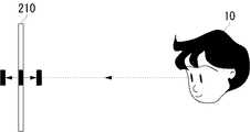
図1は、スクリーン面210に対応する基本表現空間Tを模式的に示す。ここで、基本表現空間Tはユーザ10が適正視差を認知する空間である。つまり、前方基本表現空間面12より前方あるいは後方基本表現空間面14より後方にオブジェクトが存在するとき、そのオブジェクトに対し、ユーザは生理上の違和感を生じることがある。そこで、実施の形態に係る立体画像処理装置は基本表現空間T内にオブジェクトを立体表示する。基本表現空間Tの範囲はユーザにより設定される。 FIG. 1 schematically shows a basic expression space T corresponding to the
実施の形態1
ここで、実施の形態1の概要を述べる。実施の形態1では、オブジェクト空間内に1つのカメラなどの視点を暫定的に配置する。こうして暫定的に配置されたカメラ(以下、単に「仮カメラ」という)により、立体表示すべきオブジェクトの奥行き方向の演算領域の範囲を取得する。この奥行き方向の演算領域の範囲を取得するとき、この装置は、Zバッファ法という既知の陰面消去アルゴリズムを用いる。ここでZバッファ法とは、オブジェクトのZ値を画素ごとに記憶させるとき、Z軸上で視点から近いZ値があれば、そのZ値をすでに記憶されたZ値に上書きする手法をいう。こうして画素ごとに記憶されたZ値の中で最大のZ値(以下、単に「最大Z値」という)および最小のZ値(以下、単に「最小Z値」という)を求めることで、奥行き方向の演算領域の範囲を特定する。実施の形態では、X軸方向の線分およびY軸方向の線分で区切られた画素に対応する位置でのオブジェクトのZ値を取得するものとする。
Here, an outline of the first embodiment will be described. In the first embodiment, a viewpoint such as one camera is provisionally arranged in the object space. The range of the calculation area in the depth direction of the object to be stereoscopically displayed is acquired by the provisionally arranged camera (hereinafter simply referred to as “temporary camera”). When acquiring the range of the calculation area in the depth direction, this apparatus uses a known hidden surface removal algorithm called a Z buffer method. Here, the Z buffer method is a method of overwriting an already stored Z value if there is a Z value close to the viewpoint on the Z axis when storing the Z value of the object for each pixel. In this way, the maximum Z value (hereinafter simply referred to as “maximum Z value”) and the minimum Z value (hereinafter simply referred to as “minimum Z value”) among the Z values stored for each pixel are obtained. Specify the range of the operation area. In the embodiment, it is assumed that the Z value of an object at a position corresponding to a pixel divided by a line segment in the X-axis direction and a line segment in the Y-axis direction is acquired.
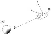
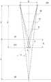
図2は、仮カメラ16により特定される演算領域R1および陰面領域R2を模式的に示す。オブジェクト空間内には、仮カメラ16、第1オブジェクト22aおよび第2オブジェクト22bが配置されている。演算領域R1は、視差画像を生成する後述の本カメラのカメラパラメータを求める演算の対象となる領域であり、代表的には演算領域R1は立体表示すべきオブジェクトの可視面が存在する領域に対応する。既述のごとく、画素ごとに記憶されたZ値の中で最大Z値および最小Z値を求めることで、奥行き方向の演算領域R1の範囲を特定する。一方、陰面領域R2は、後述の本カメラのカメラパラメータを求める演算の対象から除外される領域であり、代表的には陰面領域R2は仮カメラなどの視点から見て演算領域R1の後方にある、可視面の背後に隠れたオブジェクトの不可視面が存在する領域である。ここで、第1オブジェクト22aおよび第2オブジェクト22bをオブジェクト22と総称する。仮カメラ16によりZバッファ法を用いて奥行き方向の演算領域の範囲を取得した結果、演算領域R1の最前方演算領域面18の奥行きは最小Z値、最後方演算領域面20の奥行きは最大Z値によってそれぞれ特定される。陰面領域R2は、上述のZバッファ法により陰面消去される領域である。 FIG. 2 schematically shows the calculation region R1 and the hidden surface region R2 specified by the
この装置は、こうして求めた最大Z値および最小Z値をもとに、視差画像を取得するための複数台、例えば2台のカメラ(以下、単に「本カメラ」という)の配置場所を決め、それら2台の本カメラをオブジェクト空間内のそれぞれ異なった位置に配置する。このとき、先に暫定的に配置された仮カメラが中心にくるように2台の本カメラを配置する。さらに、このような2台の本カメラの配置決めを行うとき、この装置はユーザの適正視差をも加味する。 Based on the maximum Z value and the minimum Z value obtained in this way, this apparatus determines the arrangement location of a plurality of cameras for acquiring parallax images, for example, two cameras (hereinafter simply referred to as “main camera”), These two main cameras are arranged at different positions in the object space. At this time, the two main cameras are arranged so that the temporary camera previously provisionally arranged is at the center. Furthermore, when determining the arrangement of the two main cameras, this apparatus also takes into account the user's appropriate parallax.
この装置は、このように2台の本カメラを配置し、立体表示すべきオブジェクトに対して本カメラごとに後述の投影処理を行い、視点画像を取得し、視差画像を生成する。図3は、実施の形態1に係る立体画像処理装置が実現するオブジェクト22の立体表示の様子を示す。図1と同様のものには同じ符号を与え適宜説明を略す。図示するごとく、基本表現空間Tの前方基本表現空間面12および後方基本表現空間面14の奥行き方向の範囲内に先に求めた演算領域が含まれるよう立体表示がなされている。 This apparatus arranges two main cameras in this way, performs projection processing described later for each main camera on an object to be stereoscopically displayed, acquires a viewpoint image, and generates a parallax image. FIG. 3 illustrates a stereoscopic display of the
上述のごとく、この装置はフレームごとに上述の視差画像を生成する。本カメラの配置数が多いときなど、例えば、視差画像を生成するための演算量が多いときには、仮カメラによりZ値を取得する時間を短縮するために、以下のような処理を行ってもよい。
1)本カメラごとの視点画像の解像度よりも低い解像度でZ値を取得する。
2)立体表示すべきオブジェクトに対応し、かつ少ないデータ量からなるオブジェクトを用いて、Z値を取得する。この場合、Z値取得用の別のオブジェクト空間を準備し、そのオブジェクト空間内にそのオブジェクトを配置して、Z値を取得してもよい。As described above, this apparatus generates the above-described parallax image for each frame. For example, when the number of computations for generating a parallax image is large, such as when the number of arranged cameras is large, the following processing may be performed in order to reduce the time for acquiring the Z value by the temporary camera. .
1) The Z value is acquired at a resolution lower than the resolution of the viewpoint image for each camera.
2) The Z value is acquired using an object corresponding to the object to be displayed in three dimensions and having a small amount of data. In this case, another object space for obtaining the Z value may be prepared, the object may be arranged in the object space, and the Z value may be obtained.
図4は、実施の形態1に係る立体画像処理装置100の構成を示す。この装置は、異なる視点に対応する複数の視点画像をもとにオブジェクトを立体表示する。この立体画像処理装置100は、立体表示した画像に対するユーザからの応答をもとに立体感を調整する立体感調整部112と、立体感調整部112で特定された適正視差を保存する視差情報保持部120と、視差情報保持部120から適正視差を読みだし、三次元データから適正視差を有する視差画像を生成する視差制御部114と、表示装置のハードウエア情報を取得し、また立体表示の方式を取得する機能を有する情報取得部118と、情報取得部118で取得した情報をもとに、視差制御部114で生成された視差画像の形式を変更するフォーマット変換部116を含む。ここで、ハードウエア情報とは、例えば、表示装置そのもののハードウエアに関する情報とユーザと表示装置の距離などの要素を含んだ情報である。立体画像処理装置100にはオブジェクトと空間を描画するための三次元データが入力される。三次元データは、例えば、ワールド座標系で記述されたオブジェクトおよび空間のデータである。 FIG. 4 shows a configuration of the stereoscopic
以上の構成は、ハードウエア的には、任意のコンピュータのCPU、メモリ、その他のLSIで実現でき、ソフトウエア的にはGUI機能、視差制御機能その他の機能をもつプログラムなどによって実現されるが、ここではそれらの連携によって実現される機能ブロックを描いている。したがって、これらの機能ブロックがハードウエアのみ、ソフトウエアのみ、またはそれらの組合せによっていろいろな形で実現できることは、当業者には理解されるところであり、以降の構成についてもその事情は同様である。 The above configuration can be realized in hardware by a CPU, memory, or other LSI of an arbitrary computer, and in software, it can be realized by a program having a GUI function, a parallax control function, or other functions. Here, functional blocks realized by the cooperation are depicted. Accordingly, it is understood by those skilled in the art that these functional blocks can be realized in various forms by hardware only, software only, or a combination thereof, and the situation is the same for the subsequent configurations.
立体感調整部112は指示取得部122と視差特定部124を有する。指示取得部122は、立体表示された画像に対してユーザが適正視差の範囲を指定したとき、これを取得する。視差特定部124は、その範囲をもとに、ユーザがこの表示装置を用いたときの適正視差を特定する。適正視差は、表示装置のハードウエアに依存しない表現形式で表される。適正視差を実現することにより、ユーザの生理に適合した立体視が可能になる。このようなユーザからの適正視差の範囲の特定は、図示しないGUI(Graphical User Interface)によってなされ、その詳細は後述する。 The stereoscopic
視差制御部114は、三次元データをもとに仮想空間内にオブジェクトを定義するオブジェクト定義部128と、オブジェクト空間内に仮カメラを暫定的に配置するカメラ仮配置部130と、カメラ仮配置部130により暫定的に配置された仮カメラを基準とし、ワールド座標系上に定義された座標を透視座標系に変換する座標変換部132と、座標変換部132による座標変換がなされたとき、Zバッファ法によりZ値を取得するZ値取得部134と、Z値取得部134により取得したZ値および視差情報保持部120に保存された適正視差にしたがってカメラ間隔などのカメラパラメータを算出し、それに基づいて、2台の本カメラをオブジェクト空間内に配置するカメラ配置決定部136と、本カメラがカメラ座標系の原点となるように移動させる原点移動部138と、後述の投影処理を行う投影処理部140と、投影処理後、スクリーン座標系への変換処理を行って視点画像を生成する視点画像生成部141と、生成された複数の視点画像をもとに視差画像を生成する視差画像生成部142とを含む。カメラ配置決定部136は、実施の形態では2台の本カメラを配置するが、それ以上の台数の本カメラを配置してもよい。視差制御部114が有する各構成部の詳細は後述する。 The
情報取得部118は、例えば、立体表示の視点数、空間分割または時間分割等の立体表示装置の方式、シャッタめがねの利用があるか否か、多眼式の場合における視点画像の並び方、視差画像の中に視差が反転する視点画像の並びがあるか否か、ヘッドトラッキングの結果などをユーザからの入力により取得する。なお、ヘッドトラッキングの結果だけは例外的に図示しない経路を経て直接カメラ配置決定部136へ入力され、そこで処理される。 The
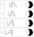
ユーザからの適正視差の範囲の特定は、以下のように行われる。図5(a)、図5(b)は、立体画像処理装置100の立体感調整部112による適正視差の特定のプロセスにおいてそれぞれ表示された左眼画像200、右眼画像202を示す。それぞれの画像には5個の黒丸が表示されており、上にいくほど近置かつ大きな視差、下へいくほど遠置かつ大きな視差が付けられている。 The range of the appropriate parallax from the user is specified as follows. FIGS. 5A and 5B show the
「近置」は異なる場所に配置された2つのカメラの視線、すなわち光軸の交差位置(以下、「光軸交差位置」ともいう)にある面(以下、「光軸交差面」ともいう)より前に立体視されるような視差が付けられている状態を指す。「遠置」は逆に光軸交差面よりうしろに立体視されるような視差が付けられている状態を指す。近置オブジェクトの視差が大きくなるほどユーザに近づいて感知され、遠置オブジェクトの視差が大きくなるほどユーザから遠ざかって見える。特に断らないかぎり、視差は近置、遠置で正負が反転せず、ともに非負の値として定義し、光軸交差面において近置視差、遠置視差ともにゼロとする。 “Neighboring” is the line of sight of two cameras arranged at different locations, that is, a plane (hereinafter also referred to as “optical axis crossing position”) at the crossing position of the optical axes (hereinafter also referred to as “optical axis crossing position”). It refers to a state in which parallax that is stereoscopically viewed before is added. On the contrary, “distant” refers to a state in which a parallax is provided so as to be stereoscopically viewed from the optical axis crossing plane. The closer the parallax of the near object, the closer to the user is sensed, and the larger the parallax of the far object, the farther away from the user. Unless otherwise specified, the parallax is defined as a non-negative value in which the positive and negative are not reversed in the near and far positions, and both the near and far parallaxes are zero at the optical axis crossing plane.
図6はこれら5個の黒丸をスクリーン面210に表示したとき、ユーザ10に感知される距離感を模式的に示す。同図では、視差が異なる5個の黒丸が同時に、または順に表示され、許容できる視差であるか否かをユーザ10が入力していく。一方、図7ではスクリーン面210への表示自体は1個の黒丸で行うが、その視差を連続的に変更する。遠置と近置それぞれの方向において許容する限界にきたとき、ユーザ10からの所定の入力指示が行われることで、許容できる視差を決定することができる。指示は通常のキー操作、マウス操作、音声による入力等、それ自体は既知の技術を利用すればよい。 FIG. 6 schematically shows a sense of distance sensed by the
また、視差の決定はより簡易的な方法で行われてもよい。同様に、基本表現空間の設定範囲の決定も簡易的な方法で行われてもよい。図8は、視差および基本表現空間の簡易決定の際に利用するテーブルを示す。基本表現空間の設定範囲が、近置空間側を多くする設定から、遠置空間側のみの設定までA〜Dの4段階のランクに分かれており、さらに、それぞれ視差が1〜5まで5段階のランクに分かれている。ここでは、例えば、最も強い立体感を好み、最も飛び出だした立体表示を好む場合はランクを5Aとする。そして、必ずしも立体表示を確認しながらランクを決定する必要はなく、ランクを決めるボタンだけが表示されていてもよい。それらの傍らに立体感確認用のボタンがあり、それを押下することで立体感を確認する画像が表示されてもよい。 Further, the determination of the parallax may be performed by a simpler method. Similarly, the setting range of the basic expression space may be determined by a simple method. FIG. 8 shows a table used for simple determination of parallax and basic expression space. The setting range of the basic expression space is divided into four ranks A to D, from the setting for increasing the near space side to the setting for only the far space side, and further, the parallax is 5 levels from 1 to 5 respectively. It is divided into ranks. Here, for example, when the user prefers the strongest stereoscopic effect and prefers the most pop-up stereoscopic display, the rank is set to 5A. And it is not always necessary to determine the rank while confirming the stereoscopic display, and only the buttons for determining the rank may be displayed. There is a button for confirming the stereoscopic effect beside them, and an image for confirming the stereoscopic effect may be displayed by pressing the button.
図6、図7のいずれの場合でも、指示取得部122は適正視差を範囲として取得でき、その近置側および遠置側の限界視差が決まる。近置最大視差は、自分に最も近い位置に見える点に許す近さに対応する視差、遠置最大視差は、自分から最も遠い位置に見える点に許す遠さに対応する視差である。ただし、一般にはユーザの生理上の問題から近置最大視差をケアすべきことが多く、以下、近置最大視差のみを限界視差とよぶ場合もある。 6 and 7, the
ここで、視差制御部114が有する各構成部の詳細を述べる。オブジェクト定義部128は、入力される三次元データに基づいて、仮想空間内にオブジェクトを定義する。図9は、ワールド座標系に第1オブジェクト22aおよび第2オブジェクト22bを配置した状態を示す。図10は、第1オブジェクト22aにモデル座標系を設定した様子を示す。同様に、第2オブジェクト22bにも別のモデル座標系を設定する。通常はオブジェクト22の中心が原点になるようモデル座標系を設定する。 Here, the detail of each component which the
カメラ仮配置部130は、図9のワールド座標系の仮想空間内に暫定的に1つの仮カメラを配置する。この仮カメラはオブジェクト空間内の演算領域の奥行き方向の範囲を取得するために配置される。上述のごとく、この演算領域は仮カメラが見ることができる可視面が存在する領域であり、つまり、立体表示がなされるべき領域である。一方、陰面領域は、仮カメラにとって演算領域の後方にある、可視面の背後に隠れて仮カメラが見ることができない不可視面が存在する領域であり、つまり、陰面領域は立体表示がなされない領域である。前述のように、実施の形態では、奥行き方向の演算領域の範囲は、Zバッファ法という既知の陰面消去アルゴリズムにより特定される。 The temporary
実施の形態1の立体画像処理装置100では、仮カメラを配置することで、奥行き方向の演算領域の範囲を特定することができ、特定された奥行き方向の演算領域の範囲およびユーザの適正視差をもとに、本カメラのカメラパラメータを後述する所定の方法で求める。そうして求められたカメラパラメータをもとに配置された本カメラは視点画像を生成し、それをもとに立体表示がなされる。これにより、ユーザが適正視差を認知する空間である基本表現空間内に先に求めた演算領域の範囲が含まれるような立体表示を実現することができる。また、本カメラのカメラパラメータを求めるとき、陰面領域を演算に含めないように演算領域を設定することで、基本表現空間内に陰面領域が含まれない立体表示を実現することができる。基本表現空間の範囲は有限であるため、ユーザがそもそも見ることができない陰面領域をその空間からはずすことは有意義である。つまり、仮カメラを暫定的に配置して演算領域を予め設定することで、基本表現空間にオブジェクトが含まれるような立体表示を実現するよう、本カメラのカメラパラメータを決定することができる。 In the stereoscopic
仮カメラの配置台数は1台であってもよい。なぜなら、本カメラは視点画像を生成するために使用されるが、仮カメラは単に奥行き方向の演算領域の範囲を取得するために使用され、仮カメラの役割はそれだけで十分である。そのため、仮カメラを複数台用いてもよいが、1台用いることで、短い時間で演算領域を画定する最大Z値および最小Z値を取得することができる。 The number of provisional cameras may be one. This is because the present camera is used to generate a viewpoint image, but the temporary camera is simply used to acquire the range of the calculation area in the depth direction, and the role of the temporary camera is sufficient. Therefore, a plurality of temporary cameras may be used. However, by using one temporary camera, the maximum Z value and the minimum Z value that define the calculation area can be acquired in a short time.
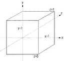
座標変換部132は、ワールド座標系で定義された座標を透視座標系に変換する。図11はカメラ座標系を示す。カメラ仮配置部130によりワールド座標系の任意の位置から任意の方向に任意の画角で仮カメラ16が据えられたとき、座標変換部132は、カメラ座標系への変換を行う。このようなワールド座標系からカメラ座標系への変換では、仮カメラ16がカメラ座標系の原点になるように全体を平行移動し、更に仮カメラ16の視線がZ軸の正方向を向くように回転移動させる。この変換にはアフィン変換が用いられる。図12、図13は透視座標系を示す。座標変換部132は、まず、図12のように、表示すべき空間を前方投影面34と後方投影面36でクリッピングする。この前方投影面34と後方投影面36は、ユーザなどにより可視オブジェクトがすべて含まれるように決定される。クリッピングの後、このビューボリュームを図13のように直方体へ変換する。図12と図13における処理を投影処理ともよぶ。 The coordinate
Z値取得部134は、座標変換部132による座標変換がなされたとき、Zバッファ法を用いて、立体表示すべきオブジェクトが含まれる仮想空間内の奥行き方向の演算領域の範囲を取得する。 When the coordinate conversion by the coordinate
上記した例では、最大Z値および最小Z値を画素ごとに取得することとしているが、Z値取得部134は、本カメラが生成する視点画像の解像度よりも低い解像度でZ値を取得してもよい。すなわち、複数の画素の集合に対して、最大、最小のZ値を取得してもよい。取得するZ値の役割はオブジェクトの奥行き方向の演算領域の範囲を特定するためのものであり、視差画像を生成するほどの解像度は必要ない。したがって、ここでは解像度を視点画像よりも低下させることによって、Z値取得のためのデータ処理量を低減し、立体表示処理全体の高速化を実現することができる。 In the above example, the maximum Z value and the minimum Z value are acquired for each pixel, but the Z
Z値取得部134は、立体表示すべきオブジェクトに対応し、かつ少ないデータ量からなるオブジェクトを用いて、Z値を取得してもよい。奥行き方向の演算領域の範囲の特定対象となるオブジェクトは、実際に立体表示されるものではなく、そこまでの正確さは必要としない。ある程度の正確さで奥行き方向の演算領域の範囲を特定できれば十分である。したがって、ここでは、少ないデータ量のオブジェクトを用いることによって、Z値取得のためのデータ処理量を低減し、立体表示処理全体の高速化を実現することができる。このとき、Z値取得用の別のオブジェクト空間を準備し、そのオブジェクト空間内にそのオブジェクトを配置してZ値を取得してもよい。 The Z
また、オブジェクトの一部あるいは全体が透過部分を有する場合は、その部分を無視してZ値を取得してもよい。これにより、基本表現空間内に透過部分が含まれないような立体表示を実現することができる。前述のごとく、基本表現空間は有限であるため、ユーザがそもそも見ることができないオブジェクトの一部あるいは全体の透過部分をその空間からはずすことは有意義である。一部あるいは全体が透過部分であるオブジェクトが他のオブジェクトの前方にあった場合、その部分を無視してZ値を取得しなければ、透過部分の後方にある、本来、Z値取得時に反映させるべき可視のオブジェクトが、Z値取得時に反映されないことがある。そのため、上述のごとく、透過部分を無視してZ値を取得することは有意義である。 If a part or the whole of the object has a transparent part, the Z value may be acquired by ignoring that part. Thereby, it is possible to realize a stereoscopic display in which a transparent portion is not included in the basic expression space. As described above, since the basic expression space is finite, it is meaningful to remove a part of the object that cannot be seen by the user or the entire transparent part from the space. If an object whose part or whole is a transparent part is in front of another object, if that part is ignored and the Z value is not acquired, it is reflected behind the transparent part when originally acquiring the Z value. Visible objects that should be visible may not be reflected when the Z value is acquired. Therefore, as described above, it is meaningful to obtain the Z value by ignoring the transmission part.
カメラ配置決定部136は、Z値取得部134により取得したZ値および視差情報保持部120に保存された適正視差にしたがってカメラ間隔などのカメラパラメータを算出し、それに基づいて2台の本カメラをオブジェクト空間内に配置する。 The camera
図14から図16は、本実施の形態に係る立体画像装置において、カメラ配置決定部136が、Z値をもとに本カメラのカメラパラメータを決めるまでの処理を示す。図14は、適正視差が実現される際のカメラ画角、画像サイズ、視差の関係を示す図である。まず、ユーザが立体感調整部112を介して決めた限界視差を暫定的に配置された仮カメラの見込み角に変換する。同図のごとく、近置と遠置の限界視差は画素数でM、Nとあらわすことができ、仮カメラの画角θが表示画面の水平画素数Lに相当するので、限界視差画素数の見込み角である、近置最大見込み角φと遠置最大見込み角ψがθ、M、N、Lであらわされる。
tan(φ/2)=Mtan(θ/2)/L
tan(ψ/2)=Ntan(θ/2)/L
このようにして、ユーザから与えられた限界視差をもとに、近置最大見込み角φおよび遠置最大見込み角ψが決まる。FIGS. 14 to 16 show processing until the camera
tan (φ / 2) = M tan (θ / 2) / L
tan (ψ / 2) = Ntan (θ / 2) / L
In this way, the near maximum prospective angle φ and the far maximum prospective angle ψ are determined based on the limit parallax given by the user.
次に本カメラのカメラパラメータが決まるまでの様子を説明する。図15における基本表現空間T(その奥行きもTと表記)は、上述のごとく、ユーザが適正視差を実現する範囲とした空間であり、立体感調整部112を介して決められる。基本表現空間Tの前面である、自分に最も近い位置に見える点に許す近さに対応する視差にあたる面からカメラ配置面、すなわち視点面208までの距離を視点距離Sとする。ここでは、基本表現空間Tおよび視点距離Sは最大Z値および最小Z値にもとづいて決められる。すなわち、基本表現空間Tに最大Z値と最小Z値との差、視点距離Sに最小Z値が設定される。基本表現空間Tおよび視点距離Sは、最大Z値に近い値や最小Z値に近い値に基づいて決められてもよい。基本表現空間Tは本来、厳密性を求めないものであるためである。本実施の形態において、本カメラは2つあり、これらの光軸交差面212の視点面208からの距離をDとする。光軸交差面212と前方投影面34までの距離をAとする。 Next, how the camera parameters of this camera are determined will be described. As described above, the basic expression space T (the depth is also expressed as T) in FIG. 15 is a space in which the user realizes an appropriate parallax, and is determined via the stereoscopic
次に、基本表現空間T内での近置および遠置の限界視差をそれぞれP、Qとすると、
E:S=P:A
E:S+T=Q:T−A
が成立する。Eは本カメラのカメラ間距離である。いま、視差の付けられていない画素である点Gは両カメラからの光軸K2が光軸交差面上212で交差する位置にあり、光軸交差面212がスクリーン面の位置となる。近置最大視差Pを生む光線K1は前方投影面34上で交差し、遠置最大視差Qを生む光線K3は後方投影面36上で交差する。Next, when the near parallax and the far parallax in the basic expression space T are P and Q, respectively,
E: S = P: A
E: S + T = Q: TA
Is established. E is the inter-camera distance of this camera. Now, the point G which is a pixel with no parallax is at a position where the optical axis K2 from both cameras intersects on the optical
PとQは、図14のようにφ、ψを用いて、
P=2(S+A)tan(φ/2)
Q=2(S+A)tan(ψ/2)
で表され、結果として、
E=2(S+A)tan(θ/2)・(SM+SN+TN)/(LT)
A=STM/(SM+SN+TN)
が得られる。上述のごとく、基本表現空間Tと視点距離Sは、最大Z値および最小Z値に基づいて算出され既知であるため、こうしてA及びEが自動的に決まり、したがって光軸交差距離Dとカメラ間距離Eが自動的に決まり、カメラパラメータが確定する。カメラ配置決定部136はこれらのパラメータにしたがって本カメラの配置を決定すれば、以降、投影処理部140および視点画像生成部141の処理を各カメラからの画像に対して独立してなすことにより、視差画像生成部142により適正視差をもった視差画像が生成および出力できる。以上のごとく、EとAはハードウエアの情報を含んでおらず、ハードウエアに依存しない表現形式が実現される。P and Q use φ and ψ as shown in FIG.
P = 2 (S + A) tan (φ / 2)
Q = 2 (S + A) tan (ψ / 2)
As a result,
E = 2 (S + A) tan (θ / 2) · (SM + SN + TN) / (LT)
A = STM / (SM + SN + TN)
Is obtained. As described above, since the basic expression space T and the viewpoint distance S are calculated and known based on the maximum Z value and the minimum Z value, A and E are thus automatically determined, and thus the optical axis crossing distance D and the distance between the cameras are determined. The distance E is automatically determined and the camera parameters are determined. If the camera
こうして、カメラ配置決定部136は、Z値取得部134により取得された奥行き方向の演算領域の範囲、つまり最大Z値および最小Z値をもとに、カメラ仮配置部130により暫定的に配置された仮カメラが中心にくるよう、2つの異なる本カメラを仮想空間内に配置することができる。 Thus, the camera
原点移動部138は、本カメラがカメラ座標系の原点となるように移動させる。投影処理部140は、上述の投影処理を行う。このとき、図12における前方投影面34と後方投影面36の位置はそれぞれ、最小Z値、最大Z値によって決められてもよい。図17は、スクリーン座標系を示す。視点画像生成部141は、投影処理後、スクリーン座標系への変換処理を行って視点画像を生成する。視差画像生成部142は、生成された複数の視点画像をもとに視差画像を生成する。 The
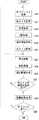
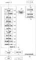
図18は、実施の形態1に係る立体画像処理装置100の処理の流れを示す。オブジェクト定義部128は、入力された三次元データをもとに仮想空間内にオブジェクトおよび座標系を設定する(S10)。カメラ仮配置部130は、オブジェクト空間内に1つの仮カメラを暫定的に配置する(S12)。座標変換部132は、ワールド座標系上に定義された座標を透視座標系に変換する(S14)。Z値取得部134は、立体表示すべきオブジェクトを含む仮想空間の奥行き方向の演算領域の範囲を取得するために、Zバッファ法を用いてZ値を取得し、最大Z値および最小Z値を求める(S16)。 FIG. 18 shows a process flow of the stereoscopic
カメラ配置決定部136は、視差情報保持部120に保存されている適正視差を取得する(S18)。カメラ配置決定部136は、最大Z値、最小Z値および適正視差をもとに、オブジェクト空間内に2台の本カメラを配置する(S20)。 The camera
原点移動部138は、本カメラがカメラ座標系の原点となるように移動させる(S22)。投影処理部140は、立体表示すべきオブジェクトに対して前述の投影処理を行い(S24)、視点画像生成部141は、二次元画像である視点画像を生成する(S26)。カメラの個数分の視点画像が生成されていない場合(S28のN)、原点移動以降の処理を繰り返す。カメラの個数分の視点画像が生成された場合(S28のY)、視差画像生成部142は、それら視点画像をもとに視差画像を生成し(S29)、1フレーム内の処理が完了する。継続して次フレームでの処理を行う場合は(S30のY)、同様に上述の処理を行う。継続して行わない場合(S30のN)、処理を終了する。以上、実施の形態1に係る立体画像処理装置100の処理の流れを説明した。 The
実施の形態2
ここで、実施の形態2の概要を述べる。実施の形態1では、オブジェクト空間内に仮カメラを暫定的に配置してZ値を取得したが、実施の形態2では、本カメラにより取得されるZ値を利用する。図19は、実施の形態2に係る立体画像処理装置100の構成を示す。以下、実施の形態1と同等の構成には同じ符号を与え適宜説明を略す。実施の形態2に係る立体画像処理装置100には、図4に示した実施の形態1に係る立体画像処理装置100と異なる構成要素であるZ値読み出し部144、Z値書き込み部146、Z値保持部150が設けられている。Z値保持部150には、Z値取得部134により取得されたZ値が格納される。そうして格納されたZ値は、少なくとも最大Z値および最小Z値が含まれる。Embodiment 2
Here, an outline of the second embodiment will be described. In the first embodiment, a temporary camera is provisionally arranged in the object space and the Z value is acquired. In the second embodiment, the Z value acquired by the camera is used. FIG. 19 shows a configuration of the stereoscopic
Z値読み出し部144は、Z値保持部150に保持された本カメラのZ値を読み出す。そのZ値は、直前のフレームにおいて本カメラにより取得されたZ値である。Z値取得部134は、少なくとも1つの本カメラによるZ値を取得してもよい。静的なオブジェクトの場合、直前のフレームと現フレームの間で、Z値に大きな変動のないことが推定される。したがって実施の形態2では、直前のフレームのZ値を現フレームのZ値として利用することで、Z値を取得する際の処理量を低減することができ、立体画像処理全体の高速化を実現することができる。また、動的なオブジェクトであっても、実際に直前のフレームと現フレームの間のオブジェクトの移動量がそう大きく変わるものではないため、動的なオブジェクトに対しても適用できる。 The Z value reading unit 144 reads the Z value of the camera held in the Z
Z値読み出し部144は、2台以上の本カメラによるZ値を統合してもよい。統合とは、カメラごとに取得したそれぞれの最大Z値および最小Z値のうち、もっとも大きい最大Z値を新たな最大Z値、もっとも小さい最小Z値を新たな最小Z値とすることである。統合することで精度が高いZ値を取得することができ、その結果、本カメラは効果的な視差画像を生成することができる。Z値書き込み部146は、Z値取得部134により取得されたZ値あるいは上述のごとく統合されたZ値をZ値保持部150に格納する。 The Z value reading unit 144 may integrate Z values obtained by two or more main cameras. Integration refers to setting the largest maximum Z value as a new maximum Z value and the smallest minimum Z value as a new minimum Z value among the respective maximum Z values and minimum Z values acquired for each camera. By integrating, it is possible to acquire a highly accurate Z value, and as a result, the camera can generate an effective parallax image. The Z
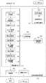
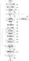
図20は、実施の形態2に係る立体画像処理装置100の処理の流れを示す。オブジェクト定義部128は、入力される三次元データをもとに仮想空間内にオブジェクトおよび座標系を設定する(S32)。カメラ仮配置部130は、そのオブジェクト空間内に1つの仮カメラを配置する(S33)。Z値読み出し部144は、Z値保持部150を参照し本カメラのZ値が保持されている場合(S34のY)、そのZ値を読み出す(S42)。保持されていない場合(S34のN)、すなわち、立体画像処理の開始時であって、1番目のフレームを処理する場合、座標変換部132は、ワールド座標系上に定義された座標を透視座標系に変換する(S38)。Z値取得部134は、立体表示すべきオブジェクトを含む仮想空間の奥行き方向の演算領域の範囲を取得するために、Zバッファ法を用いてZ値を取得し、最大Z値および最小Z値を求める(S40)。 FIG. 20 shows a processing flow of the stereoscopic
カメラ配置決定部136は、視差情報保持部120に保存されている適正視差を取得する(S44)。カメラ配置決定部136は、最大Z値、最小Z値および適正視差をもとに、オブジェクト空間内に2台の本カメラを配置する(S46)。 The camera
原点移動部138は、本カメラがカメラ座標系の原点となるように移動させる(S48)。投影処理部140は、立体表示すべきオブジェクトに対して前述の投影処理を行い(S49)、視点画像生成部141は、二次元画像である視点画像を生成する(S50)。視点画像生成時に、Z値取得部134は、Zバッファ法を用いて本カメラのZ値を取得する(S52)。Z値書き込み部146は、取得したZ値をZ値保持部150に書き込む(S54)。カメラの個数分の視点画像が生成されていない場合(S56のN)、原点移動以降の処理を繰り返す。カメラの個数分の視点画像が生成された場合(S56のY)、視差画像生成部142は、それら視点画像をもとに視差画像を生成し(S57)、1フレームの処理が完了する。次のフレームが継続する場合は(S58のY)、引き続き次フレームにおける視差画像生成処理を行う。継続しない場合(S58のN)、視差画像生成処理を終了する。以上、実施の形態2に係る立体画像処理装置100の処理の流れを説明した。 The
実施の形態3
ここで、実施の形態3の概要を述べる。実施の形態2では、静的なオブジェクトに対してとくに効果的であったが、例えば、オブジェクトが突然、カメラの視野範囲にフレームインしたときやこの立体画像処理装置がシーンチェンジを検出したとき、演算領域の範囲に急激な変化が生じているため、直前のフレームにおいて取得したZ値を現フレームのZ値として用いることが不適切なことがある。このような場合、この立体画像処理装置は、直前のZ値を用いてカメラパラメータを設定するのではなく、直前のフレームにおいて生成した視差画像よりも弱い視差を持たせた視差画像を生成するようなカメラパラメータを本カメラに適用することで対応する。Embodiment 3
Here, an outline of the third embodiment will be described. The second embodiment is particularly effective for a static object. For example, when an object suddenly enters the field of view of the camera or when this stereoscopic image processing apparatus detects a scene change, Since there is a sudden change in the range of the calculation area, it may be inappropriate to use the Z value acquired in the immediately preceding frame as the Z value of the current frame. In such a case, the stereoscopic image processing apparatus does not set the camera parameter using the immediately preceding Z value, but generates a parallax image having a weaker parallax than the parallax image generated in the immediately preceding frame. This can be done by applying various camera parameters to this camera.
図21は、実施の形態3に係る立体画像処理装置100の構成を示す。以下、実施の形態2と同等の構成には同じ符号を与え適宜説明を略す。実施の形態3に係る立体画像処理装置100には、図19に示した実施の形態2に係る立体画像処理装置100と異なる構成要素であるZ値使用判定部190、カメラパラメータ保持部152が設けられている。図21におけるカメラ配置決定部136は、図19におけるカメラ配置決定部136と比較して、本カメラを配置したときのカメラパラメータを、フレームごとにカメラパラメータ保持部152に記憶する機能をさらに有する。 FIG. 21 shows a configuration of the stereoscopic
Z値使用判定部190はZ値を使用するか否かを判定し、使用しないと判定したとき、視差制御部114にZ値の使用不可を通知する。Z値使用判定部190は、シーン判定部192およびオブジェクト検出部194を備える。 The Z value
シーン判定部192は、動きベクトルなどの既知の動き検出方法で、オブジェクトの動きの状態を検出する。そうした検出の結果、動きの多い状態であると判断したとき、シーンチェンジを検出する。このとき、視差制御部114にZ値の使用不可を通知する。 The
オブジェクト検出部194は、他のオブジェクトがオブジェクト空間の中に入ってくることを検出する。その検出方法は、最大Z値と最小Z値の差が瞬間的に所定値を超えた場合、視差制御部114にZ値の使用不可を通知する。 The
Z値使用判定部190により、Z値の使用不可が指示されたとき、カメラ配置決定部136は、前フレームにおいて生成された視差画像よりも弱い視差を持たせた視差画像を生成するよう本カメラを配置する。このとき、カメラ配置決定部136は、カメラパラメータ保持部152を参照し、前回使用したカメラ間隔よりも、小さいカメラ間隔に設定する。カメラ配置決定部136は、カメラパラメータ保持部152を参照し、最小のカメラ間隔を実現するカメラパラメータを選択して使用して配置してもよい。また、予め指定されたカメラパラメータを使用して配置してもよい。 When the Z value
演算領域の範囲に急激な変化があったとき、直前のフレームにて生成された視差画像と比べて、視差の変動が大きい視差画像が生成されることがある。こうした視差画像を観察するとき、ユーザは不快に感じることがある。とくに、視差が強すぎる視差画像が生成されるとき、この問題は顕著になる。それを回避するべく、実施の形態3における立体画像処理装置は、直前のフレームにて生成された視差画像よりも弱い視差を実現する視差画像を生成する。これにより、立体表示の際の急激な視差の変動を抑制することができ、ユーザの立体視への影響を軽減することができる。 When there is a sudden change in the range of the calculation area, a parallax image having a large variation in parallax may be generated as compared to the parallax image generated in the immediately preceding frame. When observing such a parallax image, the user may feel uncomfortable. This problem is particularly noticeable when a parallax image with too strong parallax is generated. In order to avoid this, the stereoscopic image processing apparatus according to Embodiment 3 generates a parallax image that realizes a weaker parallax than the parallax image generated in the immediately preceding frame. As a result, it is possible to suppress a rapid parallax change during stereoscopic display, and to reduce the influence on the user's stereoscopic vision.
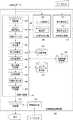
図22は、実施の形態3に係る立体画像処理装置100の処理の流れを示す。オブジェクト定義部128により、仮想空間内にオブジェクトおよび座標系が設定された(S32)後、カメラ仮配置部130は、そのオブジェクト空間内に1つの仮カメラを配置する(S33)。Z値使用判定部190は、Z値を使用するか否かを判定し、Z値を使用すると判定したとき(S60のY)、Z値読み出し部144は、Z値保持部150を参照する(S34)。Z値を使用しないと判定(S60のN)、あるいは本カメラのZ値が保持されていない(S34のN)場合、カメラ配置決定部136は、カメラパラメータ保持部152を参照し、前回使用したカメラ間隔よりも、小さいカメラ間隔を含むカメラパラメータを取得する(S64)。ここで、立体画像処理の開始時であって、1番目のフレームを処理するとき、カメラ配置決定部136は、予め指定されたカメラパラメータを使用してもよい。 FIG. 22 shows a processing flow of the stereoscopic
Z値読み出し部144は、Z値保持部150を参照し本カメラのZ値が保持されている場合(S34のY)、そのZ値を読み出し(S42)、カメラパラメータ保持部152からのカメラパラメータの取得をスキップする。カメラ配置決定部136は、視差情報保持部120に保存されている適正視差を取得する(S44)。カメラ配置決定部136は、取得したカメラパラメータがあればそのカメラパラメータを、なければ最大Z値、最小Z値をおよび適正視差をもとに、オブジェクト空間内に2台の本カメラを配置する(S46)。 When the Z value reading unit 144 refers to the Z
カメラ配置決定部136は、配置決定後のカメラパラメータをカメラパラメータ保持部152に保存する(S66)。原点移動部138は、本カメラがカメラ座標系の原点となるように移動させる(S48)。投影処理部140は、立体表示すべきオブジェクトに対して前述の投影処理を行い(S49)、視点画像生成部141は、二次元画像である視点画像を生成する(S50)。視点画像生成時に、Z値取得部134は、Zバッファ法を用いて本カメラのZ値を取得する(S52)。Z値書き込み部146は、取得したZ値をZ値保持部150に書き込む(S54)。カメラの個数分の視点画像が生成されていない場合(S56のN)、原点移動以降の処理を繰り返す。 The camera
カメラの個数分の視点画像が生成された場合(S56のY)、視差画像生成部142は、それら視点画像をもとに視差画像を生成し(S57)、1フレームの処理が完了する。次のフレームが継続する場合は(S58のY)、引き続き次フレームにおける視差画像生成処理を行う。継続しない場合(S58のN)、視差画像生成処理を終了する。以上、実施の形態3に係る立体画像処理装置100の処理の流れを説明した。 When viewpoint images for the number of cameras are generated (Y in S56), the parallax
本発明と実施の形態に係る構成の対応を例示する。「奥行き値取得部」はZ値取得部134に対応し、「視点配置部」はカメラ配置決定部136に対応し、「視差画像生成部」は視差画像生成部142に対応し、「視点仮配置部」はカメラ仮配置部130に対応し、「奥行き値使用判定部」はZ値使用判定部190に対応する。 The correspondence between the configuration of the present invention and the embodiment is illustrated. The “depth value acquisition unit” corresponds to the Z
以上、本発明を実施の形態をもとに説明した。この実施の形態は例示であり、それらの各構成要素や各処理プロセスの組合せにいろいろな変形例が可能なこと、またそうした変形例も本発明の範囲にあることは当業者に理解されるところである。 The present invention has been described based on the embodiments. This embodiment is an exemplification, and it will be understood by those skilled in the art that various modifications can be made to combinations of the respective constituent elements and processing processes, and such modifications are also within the scope of the present invention. is there.
第1変形例
実施の形態1において、仮カメラを設けた理由は、上述するごとく、本カメラの配置場所を決定づけるZ値を取得するためであり、視点画像を生成するためではない。一方、第1変形例における仮カメラは、Z値を取得するとともに視差画像のもとになる1つの視点画像を生成することができる。First Modification In the first embodiment, the reason for providing a temporary camera is to acquire a Z value that determines the placement location of the camera, as described above, and not to generate a viewpoint image. On the other hand, the temporary camera in the first modified example can acquire a Z value and generate one viewpoint image that is a basis of a parallax image.
図23は、第1変形例に係る立体画像処理装置100の構成を示す。以下、実施の形態1と同等の構成には同じ符号を与え適宜説明を略す。第1変形例に係る立体画像処理装置100には、図4に示した実施の形態1に係る立体画像処理装置100から座標変換部132を除外し、新たに仮カメラ原点移動部135、仮カメラ投影処理部137および仮カメラ視点画像生成部139が設けられる。 FIG. 23 shows a configuration of the stereoscopic
仮カメラ原点移動部135は、仮カメラがカメラ座標系の原点となるように移動させる。仮カメラ投影処理部137は、仮カメラによる立体表示すべきオブジェクトに対する前述の投影処理を行う。仮カメラ視点画像生成部139は、仮カメラにより行われた前述の投影処理後、スクリーン座標系への変換処理を行って視点画像を生成する。上述のごとく、第1変形例では、仮カメラにより視点画像を生成できるため、視差画像生成部142は、本カメラによって生成された視点画像に加え、仮カメラによって生成された視点画像をもとに、視差画像を生成することができる。 The temporary camera
このとき、カメラ配置決定部136は、取得された奥行き方向の演算領域の範囲をもとに、カメラ仮配置部130により暫定的に配置された仮カメラに加え、その仮カメラが中心にくるよう、2つの異なる本カメラを仮想空間内に配置する。カメラ配置決定部136は、1台の仮カメラが本カメラ群の中心になるように、仮カメラの両外側方向に等距離間隔で偶数台の本カメラを配置してもよい。 At this time, the camera
第2変形例
図24は、第2変形例に係る立体画像処理装置100の構成を示す図である。第2変形例は、実施の形態1に係る立体画像処理装置100に新たに演算選択情報取得部160が設けられる。演算選択情報取得部160は、オブジェクト毎に関連づけられている演算領域の範囲に含めるか否かの演算選択情報を取得し、その演算選択情報を読み取る。演算領域の範囲に含めないとする演算選択情報を有するオブジェクトを取得したとき、Z値取得部134に、そのオブジェクトを無視して、他のオブジェクトからZ値を取得するよう指示する。これにより、故意に基本表現空間を飛び出すような効果的なオブジェクトの立体表示を実現できる。また、立体画像処理装置100内の図示しないCPUが、所定のオブジェクトを演算領域の範囲に含めないようZ値取得部134に指示してもよいし、ユーザが図示しないGUIを用いて、指示してもよい。Z値取得部134は、演算選択情報取得部160により含めないとされたオブジェクトを無視して、Z値を取得する。また、演算選択情報取得部160は、実施の形態2または3に係る立体画像処理装置100にも設けても良い。Second Modification FIG. 24 is a diagram illustrating a configuration of a stereoscopic
第3変形例
実施の形態3では、Z値使用判定部190により、Z値の使用不可が指示されたとき、カメラ配置決定部136は、直前のフレームにおいて生成された視差画像よりも弱い視差を持たせた視差画像を生成するよう本カメラを配置した。第3変形例では、このような指示があったとき、視差画像生成部142は、視差を持たない二次元画像を生成してもよい。既述のごとく、ユーザが不快感を訴える多くの原因は視差の強すぎが問題であり、それを回避するべく、現フレームでは立体表示でなく平面表示を実現することで、ユーザの立体視への影響を軽減することができる。第3変形例に係る立体画像処理装置100の構成は、実施の形態3に係る立体画像処理装置100の構成と同様である。第3変形例における仮カメラは、第1変形例の場合と同様に、Z値を取得するとともに視差画像のもとになる1つの視点画像を生成することができる。Third Modification In the third embodiment, when the Z value
図25は、第3変形例に係る立体画像処理装置100の処理の流れを示す。オブジェクト定義部128は、入力される三次元データをもとに仮想空間内にオブジェクトおよび座標系を設定する(S32)。カメラ仮配置部130は、そのオブジェクト空間内に1つの仮カメラを配置する(S33)。Z値使用判定部190は、Z値を使用するか否かを判定し、Z値を使用すると判定したとき(S60のY)、Z値読み出し部144は、Z値保持部150を参照する(S34)。Z値を使用しないと判定したとき(S60のN)の処理については、後述する。Z値使用判定部190により、Z値を使用すると判定されたとき(S60のY)、Z値読み出し部144は、Z値保持部150を参照し、本カメラのZ値が保持されている場合(S34のY)、そのZ値を読み出す(S42)。保持されていない場合(S34のN)、すなわち、立体画像処理の開始時であって、1番目のフレームを処理する場合については後述する。 FIG. 25 shows a process flow of the stereoscopic
カメラ配置決定部136は、視差情報保持部120に保存されている適正視差を取得する(S44)。カメラ配置決定部136は、最大Z値、最小Z値および適正視差をもとに、オブジェクト空間内に2台の本カメラを配置する(S46)。 The camera
原点移動部138は、本カメラがカメラ座標系の原点となるように移動させる(S48)。投影処理部140は、立体表示すべきオブジェクトに対して前述の投影処理を行い(S49)、視点画像生成部141は、二次元画像である視点画像を生成する(S50)。視点画像生成時に、Z値取得部134は、Zバッファ法を用いて本カメラのZ値を取得する(S52)。Z値書き込み部146は、取得したZ値をZ値保持部150に書き込む(S54)。カメラの個数分の視点画像が生成されていない場合(S56のN)、原点移動以降の処理を繰り返す。カメラの個数分の視点画像が生成された場合(S56のY)、視差画像生成部142は、それら視点画像をもとに視差画像を生成し(S57)、1フレームの処理が完了する。 The
Z値使用判定部190は、Z値を使用しないと判定したとき(S60のN)、つまり,演算領域の範囲に急激な変化があったとき、あるいは、本カメラのZ値が保持されていないとされたとき(S34のN)、原点移動部138は、仮カメラがカメラ座標系の原点となるように移動させる(S72)。投影処理部140は、立体表示すべきオブジェクトに対して前述の投影処理を行う(S73)。視点画像生成部141は、二次元画像である視点画像を生成する(S74)。Z値取得部134は、視点画像生成時に仮カメラによるZ値を取得する(S76)。Z値書き込み部146は、取得したZ値をZ値保持部150に保存する(S78)。視差画像生成部142は、視差画像を生成せず視差を持たない二次元画像を生成し(S80)、1フレームの処理が完了する。 The Z value
次のフレームが継続する場合は(S58のY)、引き続き次フレームにおける視差画像生成処理を行う。継続しない場合(S58のN)、視差画像生成処理を終了する。以上、第3変形例に係る立体画像処理装置100の処理の流れを説明した。このように1つの仮カメラによって得られた視点画像を表示することで平面表示を実現することができる。 When the next frame continues (Y in S58), the parallax image generation process in the next frame is continued. When not continuing (N of S58), a parallax image generation process is complete | finished. The processing flow of the stereoscopic
第4変形例
図26は、角度を用いて奥行き方向の演算領域の範囲を取得する様子を模式的に示す。実施の形態では、X軸方向の線分およびY軸方向の線分で区切られた画素に対応する位置でのオブジェクトのZ値を取得したが、第4変形例では、図示のごとく、第1オブジェクト22aおよび第2オブジェクト22bにおける第1角度θと第2角度φが同じ点の座標に対応するオブジェクトのZ値を取得し、最大Z値および最小Z値を求めてもよい。このとき、Z値取得用の別の仮想空間を準備して、最大Z値および最小Z値を求めてもよい。Fourth Modification FIG. 26 schematically shows a state in which the range of the calculation area in the depth direction is acquired using an angle. In the embodiment, the Z value of the object at the position corresponding to the pixel divided by the line segment in the X-axis direction and the line segment in the Y-axis direction is acquired. However, in the fourth modified example, as illustrated, the first value The Z value of the object corresponding to the coordinates of the same point at which the first angle θ and the second angle φ in the
第5変形例
実施の形態では、カメラ配置決定部136は仮カメラを中心とし2台の本カメラを配置したが、第5変形例では、2つの異なる本カメラの両外側方向に、カメラ間の距離が2つの本カメラの距離間隔となるように、複数台、例えば4台の本カメラを配置する。図27は4台の第1〜第4本カメラ24a〜24dによる4眼式のカメラ配置を示す。より中央に近い第2本カメラ24bと第3本カメラ24cの間で決めた前述のAおよびEを他のカメラ間隔に流用してもよい。これにより、本カメラの配置場所を決めるためのカメラパラメータを算出する時間を短縮することができ、立体画像処理全体の高速化を実現することができる。Fifth Modification In the embodiment, the camera
第6変形例
実施の形態では、カメラ仮配置部130は、仮想空間内における仮カメラの配置場所をフレームごとに決めていったが、第6変形例では、カメラ仮配置部130は、直前のフレームにおいて、カメラ配置決定部136により配置された本カメラの視野範囲を含む視野範囲を有するよう、仮カメラを配置してもよい。図28は、仮カメラ16と4台の第1〜第4本カメラ24a〜24dとの位置関係を示す。図示のごとく、直前のフレームにて配置された4台の第1〜第4本カメラ24a〜24dの視野範囲を含む視野範囲を実現するよう、仮カメラ16が配置されている。Sixth Modification In the embodiment, the camera
第7変形例
図29は、第7変形例に係る立体画像処理装置100の構成を示す図である。第7変形例では、実施の形態2に係る立体画像処理装置100に新たに動作予測部170および変位量予測部172が設けられる。動作予測部170は、各オブジェクトの前後方向への動きおよび動作速度などを検出し、その検出結果をもとにそれらオブジェクトの将来の動きの状態を予測する。変位量予測部172は、動作予測部170による予測結果をもとに、それら立体表示すべきオブジェクトが包含される所定の領域の変位量を予測する。例えば、変位量予測部172は、この変位量を直前のフレームにおける奥行き方向の演算領域の範囲に加算することで、現フレームにおける奥行き方向の演算領域の範囲を予測することができる。このとき、奥行き方向の演算領域の範囲をもとにZ値を取得して、現フレームにおけるZ値の予測値としてもよい。また、変位量予測部172は、この変位量に応じたカメラの配置を実現するようなカメラ間隔や光軸交差位置などのカメラパラメータを予測することができる。Seventh Modification FIG. 29 is a diagram illustrating a configuration of a stereoscopic
カメラ配置決定部136は、変位量予測部172による奥行き方向の演算領域の範囲やカメラパラメータの予測結果をもとに、仮想空間内における本カメラの配置場所を決定する。例えば、変位量予測部172により奥行き方向の演算領域の範囲が著しく拡張されるとの予測結果が得られているとき、カメラ配置決定部136は現フレームにおける本カメラのカメラ間隔が小さくなるよう本カメラを配置する。また、カメラ配置決定部136は、変位量予測部172による奥行き方向の演算領域の範囲の予測結果の変化に応じて、本カメラの光軸交差位置を調整してもよい。例えば、カメラ配置決定部136は、演算領域の最前方演算領域面18から光軸交差位置までの距離と、光軸交差位置から演算領域の最後方演算領域面20までの距離との比が一定となるように光軸交差位置を調整して、本カメラを配置してもよい。これにより、オブジェクトの動きに対応した本カメラの配置が実現でき、立体画像処理装置100は、より高精度の視点画像を得ることができる。 The camera
第8変形例
実施の形態3では、Z値使用判定部190によりZ値を使用しないと判定されたとき、直前のフレームにおいて生成された視差画像よりも弱い視差を持たせた視差画像を現フレームにて生成した。第8変形例では、Z値使用判定部190によりZ値を使用しないと判定されたとき、Z値取得部134は、直前のフレームにおいて取得されたZ値を用いず、上述の投影処理のクリッピング時において仮設定される前方投影面34と後方投影面36を用いて、奥行き方向の演算領域の範囲を取得してもよい。上述のごとく、前方投影面34と後方投影面36は、そもそも可視オブジェクトがすべて含まれるように決定されるため、立体表示すべきオブジェクトが含まれる演算領域として、前方投影面34と後方投影面36間に囲まれた領域を用いるのは、効果的である。Eighth Modification In Embodiment 3, when the Z value
第9変形例
実施の形態3では、Z値使用判定部190によりZ値を使用しないと判定されたとき、直前のフレームにおいて生成された視差画像よりも弱い視差を持たせた視差画像を現フレームにて生成した。本カメラにより視点画像を生成するとともにZ値を取得する場合、立体画像処理に関する時間的な問題は少ないが、その視点画像の生成とは別の契機でZ値の取得処理が必要な場合には、簡易な取得方法で処理の高速化を図る必要がある。このとき、第9変形例として、Z値取得部134は視点画像の解像度よりも低い解像度でZ値を取得してもよい。既述のごとく、取得するZ値というのはオブジェクトの奥行き方向の演算領域の範囲を特定するためのものであり、視差画像を生成するほどの解像度は必要ない。したがって、ここでは解像度を視点画像よりも低下させることによって、Z値取得のためのデータ処理量を低減し、立体表示処理全体の高速化を実現することができる。また、Z値取得部134によるZ値取得処理がシーンチェンジまでに完了できないときは、その取得処理が完了するまで、シーンチェンジを遅延させてもよい。Ninth Modification In Embodiment 3, when the Z value
図30は、第9変形例に係る立体画像処理装置100の処理の流れを示す。オブジェクト定義部128により、仮想空間内にオブジェクトおよび座標系が設定された(S32)後、カメラ仮配置部130は、そのオブジェクト空間内に1つの仮カメラを配置する(S33)。Z値使用判定部190は、Z値を使用するか否かを判定し、Z値を使用すると判定したとき(S60のY)、Z値読み出し部144は、Z値保持部150を参照する(S34)。 FIG. 30 shows a flow of processing of the stereoscopic
Z値を使用しないと判定したとき(S60のN)、あるいはZ値保持部150にZ値が保持されていないとき(S34のN)、座標変換部132は、ワールド座標系上に定義された座標を透視座標系に変換する(S38)。Z値取得部134は、立体表示すべきオブジェクトを含む仮想空間の奥行き方向の演算領域の範囲を取得するために、Zバッファ法を用いてZ値を取得し、最大Z値および最小Z値を求める(S40)。このとき、上述のごとく、Z値取得部134は視点画像の解像度よりも低い解像度でZ値を取得してもよい。Z値取得部134によるZ値取得処理がシーンチェンジまでに完了できないときは、その取得処理が完了するまで、シーンチェンジを遅延させてもよい。 When it is determined that the Z value is not used (N in S60), or when the Z value is not held in the Z value holding unit 150 (N in S34), the coordinate
Z値読み出し部144は、Z値保持部150にZ値が保持されているとき、Z値を読み出す(S42)。カメラ配置決定部136は、視差特定部124に保存されている適正視差を取得する(S44)。カメラ配置決定部136は、最大Z値、最小Z値および適正視差をもとに、オブジェクト空間内に2台の本カメラを配置する(S46)。 The Z value reading unit 144 reads the Z value when the Z value is held in the Z value holding unit 150 (S42). The camera
原点移動部138は、本カメラがカメラ座標系の原点となるように移動させる(S48)。投影処理部140は、立体表示すべきオブジェクトに対して前述の投影処理を行い(S49)、視点画像生成部141は、二次元画像である視点画像を生成する(S50)。視点画像生成時に、Z値取得部134は、Zバッファ法を用いて本カメラのZ値を取得する(S52)。Z値書き込み部146は、取得したZ値をZ値保持部150に書き込む(S54)。 The
カメラの個数分の視点画像が生成されていない場合(S56のN)、原点移動以降の処理を繰り返す。カメラの個数分の視点画像が生成された場合(S56のY)、視差画像生成部142は、それら視点画像をもとに視差画像を生成し(S57)、1フレームの処理が完了する。次のフレームが継続する場合は(S58のY)、引き続き次フレームにおける視差画像生成処理を行う。継続しない場合(S58のN)、視差画像生成処理を終了する。以上、第9変形例に係る立体画像処理装置100の処理の流れを説明した。 If viewpoint images for the number of cameras have not been generated (N in S56), the processing after the origin movement is repeated. When viewpoint images for the number of cameras are generated (Y in S56), the parallax
第10変形例
実施の形態ではスクリーン面に対して水平方向にカメラを配置したが、垂直方向に配置してもよく、水平方向の場合と同様の効果を享受できる。Tenth Modification Although the camera is arranged in the horizontal direction with respect to the screen surface in the embodiment, it may be arranged in the vertical direction, and the same effect as in the horizontal direction can be enjoyed.
第11変形例
実施の形態では、Zバッファ法によりオブジェクトのZ値を取得したが、本変形例として、デプスマップを取得して奥行き方向の演算領域の範囲を特定してもよい。本変形例でも実施の形態と同様の効果を享受できる。Eleventh Modification In the embodiment, the Z value of the object is acquired by the Z buffer method. However, as a modification, a depth map may be acquired to specify the range of the calculation area in the depth direction. This modification can also enjoy the same effects as the embodiment.
第12変形例
実施の形態1から実施の形態3を任意に組み合わせた形態も有効である。本変形例によれば、実施の形態1から実施の形態3を任意に組み合わせた効果が得られる。Twelfth Modification A form in which
16 仮カメラ、22 オブジェクト、24 本カメラ、100 立体画像処理装置、130 カメラ仮配置部、134 Z値取得部、136 カメラ配置決定部、142 視差画像生成部、160 演算選択情報取得部、170 動作予測部、172 変位量予測部、190 Z値使用判定部、R1 演算領域。 16 temporary cameras, 22 objects, 24 cameras, 100 stereoscopic image processing apparatus, 130 camera temporary arrangement unit, 134 Z value acquisition unit, 136 camera arrangement determination unit, 142 parallax image generation unit, 160 calculation selection information acquisition unit, 170 operation Prediction unit, 172 displacement amount prediction unit, 190 Z value use determination unit, R1 calculation area.
Claims (16)
Translated fromJapanese前記立体表示すべきオブジェクトが含まれる仮想空間内の奥行き方向の演算領域の範囲を取得する奥行き値取得部と、
前記取得された奥行き方向の演算領域の範囲をもとに、複数の異なる視点を前記仮想空間内に配置する視点配置部と、
前記複数の異なる視点からの視点画像をもとに、視差画像を生成する視差画像生成部とを、
備えることを特徴とする立体画像処理装置。A stereoscopic image processing apparatus that stereoscopically displays an object based on a plurality of viewpoint images corresponding to different viewpoints,
A depth value acquisition unit for acquiring a range of a calculation region in a depth direction in a virtual space including the object to be stereoscopically displayed;
A viewpoint arrangement unit that arranges a plurality of different viewpoints in the virtual space based on the acquired range of the calculation area in the depth direction;
A parallax image generation unit that generates a parallax image based on viewpoint images from the plurality of different viewpoints,
A stereoscopic image processing apparatus comprising:
前記動作予測部により予測されたオブジェクトの将来の動きの状態をもとに、前記オブジェクトが包含される所定の領域の変位量を予測する変位量予測部と、
をさらに備え、前記視点配置部は、前記変位量予測部により予測された所定の領域の変位量に基づいて、前記複数の異なる視点を前記仮想空間内に配置することを特徴とする請求項9から13のいずれかに記載の立体画像処理装置。A motion prediction unit that detects a state of motion of the object and predicts a state of future motion of the object based on the detection result;
Based on the state of future movement of the object predicted by the motion prediction unit, a displacement amount prediction unit that predicts a displacement amount of a predetermined region in which the object is included, and
The viewpoint arrangement unit arranges the plurality of different viewpoints in the virtual space based on a displacement amount of a predetermined region predicted by the displacement amount prediction unit. 14. The stereoscopic image processing apparatus according to any one of.
前記取得された奥行き方向の演算領域の範囲をもとに、複数の異なる視点を前記仮想空間内に配置するステップと、
前記複数の異なる視点からの視点画像をもとに、視差画像を生成するステップと、
を有することを特徴とする立体画像処理方法。Obtaining a range of a calculation area in the depth direction in a virtual space including an object for stereoscopic display;
Arranging a plurality of different viewpoints in the virtual space based on the acquired range of the calculation area in the depth direction;
Generating a parallax image based on viewpoint images from the plurality of different viewpoints;
A stereoscopic image processing method characterized by comprising:
Priority Applications (3)
| Application Number | Priority Date | Filing Date | Title |
|---|---|---|---|
| JP2004104148AJP2005295004A (en) | 2004-03-31 | 2004-03-31 | Stereoscopic image processing method and apparatus thereof |
| CNA200510055045XACN1678085A (en) | 2004-03-31 | 2005-03-15 | Method and apparatus for processing three-dimensional images |
| US11/086,493US20050219239A1 (en) | 2004-03-31 | 2005-03-23 | Method and apparatus for processing three-dimensional images |
Applications Claiming Priority (1)
| Application Number | Priority Date | Filing Date | Title |
|---|---|---|---|
| JP2004104148AJP2005295004A (en) | 2004-03-31 | 2004-03-31 | Stereoscopic image processing method and apparatus thereof |
Publications (1)
| Publication Number | Publication Date |
|---|---|
| JP2005295004Atrue JP2005295004A (en) | 2005-10-20 |
Family
ID=35050344
Family Applications (1)
| Application Number | Title | Priority Date | Filing Date |
|---|---|---|---|
| JP2004104148APendingJP2005295004A (en) | 2004-03-31 | 2004-03-31 | Stereoscopic image processing method and apparatus thereof |
Country Status (3)
| Country | Link |
|---|---|
| US (1) | US20050219239A1 (en) |
| JP (1) | JP2005295004A (en) |
| CN (1) | CN1678085A (en) |
Cited By (11)
| Publication number | Priority date | Publication date | Assignee | Title |
|---|---|---|---|---|
| JP2010263542A (en)* | 2009-05-11 | 2010-11-18 | National Institute Of Information & Communication Technology | Remote communication system, control device, and program |
| CN102143371A (en)* | 2010-01-28 | 2011-08-03 | 株式会社东芝 | Image processing apparatus, 3D display apparatus and image processing method |
| JP2011160302A (en)* | 2010-02-02 | 2011-08-18 | Waseda Univ | Three-dimensional image producing apparatus and program |
| JP2011176823A (en)* | 2010-01-28 | 2011-09-08 | Toshiba Corp | Image processing apparatus, 3d display apparatus, and image processing method |
| CN102193705A (en)* | 2010-03-02 | 2011-09-21 | 鸿富锦精密工业(深圳)有限公司 | System and method for controlling three-dimensional multimedia image interaction |
| JP2012129710A (en)* | 2010-12-14 | 2012-07-05 | Canon Inc | Display controller, display control method, and program |
| JP2012141819A (en)* | 2010-12-29 | 2012-07-26 | Nintendo Co Ltd | Image processing system, image processing program, image processing method and image processing device |
| JP2012191366A (en)* | 2011-03-09 | 2012-10-04 | Fujitsu Ltd | Generation device and generation method |
| JP2012203755A (en)* | 2011-03-28 | 2012-10-22 | Toshiba Corp | Image processing device and image processing method |
| JP2012252583A (en)* | 2011-06-03 | 2012-12-20 | Nintendo Co Ltd | Display control program, display device, display system, and display control method |
| JP2012252566A (en)* | 2011-06-03 | 2012-12-20 | Nintendo Co Ltd | Information processing program, information processor, information processing system, and information processing method |
Families Citing this family (45)
| Publication number | Priority date | Publication date | Assignee | Title |
|---|---|---|---|---|
| US7298370B1 (en)* | 2005-04-16 | 2007-11-20 | Apple Inc. | Depth ordering of planes and displaying interconnects having an appearance indicating data characteristics |
| US8698844B1 (en)* | 2005-04-16 | 2014-04-15 | Apple Inc. | Processing cursor movements in a graphical user interface of a multimedia application |
| JP4508049B2 (en)* | 2005-09-05 | 2010-07-21 | 株式会社日立製作所 | 360 ° image capturing device |
| KR100762670B1 (en)* | 2006-06-07 | 2007-10-01 | 삼성전자주식회사 | Method and apparatus for generating disparity map from stereo image and method and apparatus for stereo matching therefor |
| US9098647B2 (en) | 2008-03-10 | 2015-08-04 | Apple Inc. | Dynamic viewing of a three dimensional space |
| US8089479B2 (en) | 2008-04-11 | 2012-01-03 | Apple Inc. | Directing camera behavior in 3-D imaging system |
| JP5567562B2 (en)* | 2008-07-24 | 2014-08-06 | コーニンクレッカ フィリップス エヌ ヴェ | Versatile 3D image format |
| JP4637942B2 (en)* | 2008-09-30 | 2011-02-23 | 富士フイルム株式会社 | Three-dimensional display device, method and program |
| US9619917B2 (en) | 2008-10-03 | 2017-04-11 | Apple Inc. | Depth of field for a camera in a media-editing application |
| KR20110129903A (en) | 2009-02-18 | 2011-12-02 | 코닌클리케 필립스 일렉트로닉스 엔.브이. | Transmission of 3D viewer metadata |
| EP2416583A4 (en)* | 2009-03-30 | 2013-12-25 | Nec Corp | PICTURE DISPLAY DEVICE, PICTURE GENERATING DEVICE, PICTURE DISPLAY METHOD, PICTURE PRODUCTION METHOD, AND NON-TRANSITORY COMPUTER-READABLE MEDIUM WITH A PROGRAM STORED THEREFOR |
| KR20100135032A (en)* | 2009-06-16 | 2010-12-24 | 삼성전자주식회사 | 3D image conversion device and method of 2D image |
| JP5415170B2 (en)* | 2009-07-21 | 2014-02-12 | 富士フイルム株式会社 | Compound eye imaging device |
| CN102165516A (en)* | 2009-08-31 | 2011-08-24 | 松下电器产业株式会社 | Image display control device, image display control method and integrated circuit |
| JP2011082919A (en)* | 2009-10-09 | 2011-04-21 | Sony Corp | Image processing device and method, and program |
| JP2011139281A (en)* | 2009-12-28 | 2011-07-14 | Sony Corp | Three-dimensional image generator, three-dimensional image display device, three-dimensional image generation method, and program |
| JP5227993B2 (en)* | 2010-03-31 | 2013-07-03 | 株式会社東芝 | Parallax image generation apparatus and method thereof |
| JP5573379B2 (en)* | 2010-06-07 | 2014-08-20 | ソニー株式会社 | Information display device and display image control method |
| WO2011155212A1 (en)* | 2010-06-11 | 2011-12-15 | 富士フイルム株式会社 | 3d image display device, 3d imaging device, and method |
| US8631047B2 (en) | 2010-06-15 | 2014-01-14 | Apple Inc. | Editing 3D video |
| JP4937390B2 (en)* | 2010-08-24 | 2012-05-23 | 株式会社東芝 | 3D image display device and 3D image glasses |
| US8907983B2 (en) | 2010-10-07 | 2014-12-09 | Aria Glassworks, Inc. | System and method for transitioning between interface modes in virtual and augmented reality applications |
| JP2012090094A (en)* | 2010-10-20 | 2012-05-10 | Sony Corp | Image processing device, image processing method, and program |
| JP5066244B2 (en)* | 2010-10-29 | 2012-11-07 | 株式会社東芝 | Video playback apparatus and video playback method |
| JP5594067B2 (en)* | 2010-11-02 | 2014-09-24 | ソニー株式会社 | Image processing apparatus and image processing method |
| US9070219B2 (en) | 2010-11-24 | 2015-06-30 | Aria Glassworks, Inc. | System and method for presenting virtual and augmented reality scenes to a user |
| US9041743B2 (en)* | 2010-11-24 | 2015-05-26 | Aria Glassworks, Inc. | System and method for presenting virtual and augmented reality scenes to a user |
| WO2012071466A2 (en) | 2010-11-24 | 2012-05-31 | Aria Glassworks, Inc. | System and method for acquiring virtual and augmented reality scenes by a user |
| JP5050094B2 (en)* | 2010-12-21 | 2012-10-17 | 株式会社東芝 | Video processing apparatus and video processing method |
| US8953022B2 (en) | 2011-01-10 | 2015-02-10 | Aria Glassworks, Inc. | System and method for sharing virtual and augmented reality scenes between users and viewers |
| US9983685B2 (en)* | 2011-01-17 | 2018-05-29 | Mediatek Inc. | Electronic apparatuses and methods for providing a man-machine interface (MMI) |
| US9118970B2 (en) | 2011-03-02 | 2015-08-25 | Aria Glassworks, Inc. | System and method for embedding and viewing media files within a virtual and augmented reality scene |
| US9022864B2 (en) | 2011-06-03 | 2015-05-05 | Nintendo Co., Ltd. | Apparatus and method for controlling objects on a stereoscopic display |
| JP2012253690A (en)* | 2011-06-06 | 2012-12-20 | Namco Bandai Games Inc | Program, information storage medium, and image generation system |
| US9392251B2 (en)* | 2011-12-29 | 2016-07-12 | Samsung Electronics Co., Ltd. | Display apparatus, glasses apparatus and method for controlling depth |
| WO2013102790A2 (en)* | 2012-01-04 | 2013-07-11 | Thomson Licensing | Processing 3d image sequences cross reference to related applications |
| US9286723B2 (en)* | 2012-04-04 | 2016-03-15 | Parag Tope | Method and system of discretizing three-dimensional space and objects for two-dimensional representation of space and objects |
| JP6099892B2 (en)* | 2012-07-09 | 2017-03-22 | パナソニック インテレクチュアル プロパティ コーポレーション オブ アメリカPanasonic Intellectual Property Corporation of America | Video display device |
| US9626799B2 (en) | 2012-10-02 | 2017-04-18 | Aria Glassworks, Inc. | System and method for dynamically displaying multiple virtual and augmented reality scenes on a single display |
| JP6143469B2 (en)* | 2013-01-17 | 2017-06-07 | キヤノン株式会社 | Information processing apparatus, information processing method, and program |
| US10769852B2 (en) | 2013-03-14 | 2020-09-08 | Aria Glassworks, Inc. | Method for simulating natural perception in virtual and augmented reality scenes |
| US9836879B2 (en)* | 2013-04-16 | 2017-12-05 | Autodesk, Inc. | Mesh skinning technique |
| US10977864B2 (en) | 2014-02-21 | 2021-04-13 | Dropbox, Inc. | Techniques for capturing and displaying partial motion in virtual or augmented reality scenes |
| JP7102173B2 (en)* | 2018-03-09 | 2022-07-19 | キヤノン株式会社 | Information processing equipment, information processing methods, and programs |
| JP7341674B2 (en)* | 2019-02-27 | 2023-09-11 | キヤノン株式会社 | Information processing device, information processing method and program |
Citations (4)
| Publication number | Priority date | Publication date | Assignee | Title |
|---|---|---|---|---|
| JPH0974573A (en)* | 1995-06-29 | 1997-03-18 | Matsushita Electric Ind Co Ltd | 3D CG image generator |
| JP2001128195A (en)* | 1999-10-29 | 2001-05-11 | Atr Ningen Joho Tsushin Kenkyusho:Kk | Stereoscopic image correction device, stereoscopic image display device, and recording medium storing stereoscopic image correction processing program |
| JP2002008040A (en)* | 2000-06-16 | 2002-01-11 | Matsushita Electric Ind Co Ltd | Three-dimensional information detection device and three-dimensional information detection method |
| JP2004007396A (en)* | 2002-03-27 | 2004-01-08 | Sanyo Electric Co Ltd | Stereoscopic image processing method and device |
Family Cites Families (24)
| Publication number | Priority date | Publication date | Assignee | Title |
|---|---|---|---|---|
| US5764231A (en)* | 1992-05-15 | 1998-06-09 | Eastman Kodak Company | Method and apparatus for creating geometric depth images using computer graphics |
| US5850352A (en)* | 1995-03-31 | 1998-12-15 | The Regents Of The University Of California | Immersive video, including video hypermosaicing to generate from multiple video views of a scene a three-dimensional video mosaic from which diverse virtual video scene images are synthesized, including panoramic, scene interactive and stereoscopic images |
| US6005607A (en)* | 1995-06-29 | 1999-12-21 | Matsushita Electric Industrial Co., Ltd. | Stereoscopic computer graphics image generating apparatus and stereoscopic TV apparatus |
| JPH11119303A (en)* | 1997-10-20 | 1999-04-30 | Fujitsu Ltd | Monitoring system and monitoring method |
| US6710903B2 (en)* | 1998-07-29 | 2004-03-23 | Sony Corporation | Method and apparatus for formulating image data, method and apparatus for converting image data, method and apparatus for formulating holographic stereogram, recording medium and data transmitting method |
| US6366370B1 (en)* | 1998-12-30 | 2002-04-02 | Zebra Imaging, Inc. | Rendering methods for full parallax autostereoscopic displays |
| JP3634677B2 (en)* | 1999-02-19 | 2005-03-30 | キヤノン株式会社 | Image interpolation method, image processing method, image display method, image processing apparatus, image display apparatus, and computer program storage medium |
| US6771809B1 (en)* | 2000-04-28 | 2004-08-03 | Orametrix, Inc. | Method and system for registering data |
| GB2354389A (en)* | 1999-09-15 | 2001-03-21 | Sharp Kk | Stereo images with comfortable perceived depth |
| WO2001069931A1 (en)* | 2000-03-10 | 2001-09-20 | Sensormatic Electronics Corporation | Method and apparatus for video surveillance with defined zones |
| US7085409B2 (en)* | 2000-10-18 | 2006-08-01 | Sarnoff Corporation | Method and apparatus for synthesizing new video and/or still imagery from a collection of real video and/or still imagery |
| WO2002037856A1 (en)* | 2000-11-06 | 2002-05-10 | Dynapel Systems, Inc. | Surveillance video camera enhancement system |
| US6573912B1 (en)* | 2000-11-07 | 2003-06-03 | Zaxel Systems, Inc. | Internet system for virtual telepresence |
| US7106361B2 (en)* | 2001-02-12 | 2006-09-12 | Carnegie Mellon University | System and method for manipulating the point of interest in a sequence of images |
| JP4075418B2 (en)* | 2002-03-15 | 2008-04-16 | ソニー株式会社 | Image processing apparatus, image processing method, printed material manufacturing apparatus, printed material manufacturing method, and printed material manufacturing system |
| US6853398B2 (en)* | 2002-06-21 | 2005-02-08 | Hewlett-Packard Development Company, L.P. | Method and system for real-time video communication within a virtual environment |
| US7466336B2 (en)* | 2002-09-05 | 2008-12-16 | Eastman Kodak Company | Camera and method for composing multi-perspective images |
| JP4228646B2 (en)* | 2002-10-02 | 2009-02-25 | 株式会社セガ | Stereoscopic image generation method and stereoscopic image generation apparatus |
| US7251346B2 (en)* | 2002-11-19 | 2007-07-31 | Honda Motor Co., Ltd. | Moving object detection device, moving object detection method, and moving object detection program |
| US8081206B2 (en)* | 2002-11-21 | 2011-12-20 | Vision Iii Imaging, Inc. | Critical alignment of parallax images for autostereoscopic display |
| GB2400513B (en)* | 2003-03-14 | 2005-10-05 | British Broadcasting Corp | Video processing |
| EP1646006B1 (en)* | 2003-07-11 | 2010-03-10 | Toyota Jidosha Kabushiki Kaisha | Image processing device, image processing method, image processing program, and recording medium |
| US7643025B2 (en)* | 2003-09-30 | 2010-01-05 | Eric Belk Lange | Method and apparatus for applying stereoscopic imagery to three-dimensionally defined substrates |
| US7376250B2 (en)* | 2004-01-05 | 2008-05-20 | Honda Motor Co., Ltd. | Apparatus, method and program for moving object detection |
- 2004
- 2004-03-31JPJP2004104148Apatent/JP2005295004A/enactivePending
- 2005
- 2005-03-15CNCNA200510055045XApatent/CN1678085A/enactivePending
- 2005-03-23USUS11/086,493patent/US20050219239A1/ennot_activeAbandoned
Patent Citations (4)
| Publication number | Priority date | Publication date | Assignee | Title |
|---|---|---|---|---|
| JPH0974573A (en)* | 1995-06-29 | 1997-03-18 | Matsushita Electric Ind Co Ltd | 3D CG image generator |
| JP2001128195A (en)* | 1999-10-29 | 2001-05-11 | Atr Ningen Joho Tsushin Kenkyusho:Kk | Stereoscopic image correction device, stereoscopic image display device, and recording medium storing stereoscopic image correction processing program |
| JP2002008040A (en)* | 2000-06-16 | 2002-01-11 | Matsushita Electric Ind Co Ltd | Three-dimensional information detection device and three-dimensional information detection method |
| JP2004007396A (en)* | 2002-03-27 | 2004-01-08 | Sanyo Electric Co Ltd | Stereoscopic image processing method and device |
Cited By (13)
| Publication number | Priority date | Publication date | Assignee | Title |
|---|---|---|---|---|
| JP2010263542A (en)* | 2009-05-11 | 2010-11-18 | National Institute Of Information & Communication Technology | Remote communication system, control device, and program |
| CN102143371A (en)* | 2010-01-28 | 2011-08-03 | 株式会社东芝 | Image processing apparatus, 3D display apparatus and image processing method |
| JP2011176823A (en)* | 2010-01-28 | 2011-09-08 | Toshiba Corp | Image processing apparatus, 3d display apparatus, and image processing method |
| JP2011160302A (en)* | 2010-02-02 | 2011-08-18 | Waseda Univ | Three-dimensional image producing apparatus and program |
| CN102193705A (en)* | 2010-03-02 | 2011-09-21 | 鸿富锦精密工业(深圳)有限公司 | System and method for controlling three-dimensional multimedia image interaction |
| JP2012129710A (en)* | 2010-12-14 | 2012-07-05 | Canon Inc | Display controller, display control method, and program |
| JP2012141819A (en)* | 2010-12-29 | 2012-07-26 | Nintendo Co Ltd | Image processing system, image processing program, image processing method and image processing device |
| JP2012191366A (en)* | 2011-03-09 | 2012-10-04 | Fujitsu Ltd | Generation device and generation method |
| US9288473B2 (en) | 2011-03-09 | 2016-03-15 | Fujitsu Limited | Creating apparatus and creating method |
| JP2012203755A (en)* | 2011-03-28 | 2012-10-22 | Toshiba Corp | Image processing device and image processing method |
| JP2012252583A (en)* | 2011-06-03 | 2012-12-20 | Nintendo Co Ltd | Display control program, display device, display system, and display control method |
| JP2012252566A (en)* | 2011-06-03 | 2012-12-20 | Nintendo Co Ltd | Information processing program, information processor, information processing system, and information processing method |
| US9049424B2 (en) | 2011-06-03 | 2015-06-02 | Nintendo Co., Ltd. | Recording medium storing display control program for controlling display capable of providing stereoscopic display, display system, display control method, and display |
Also Published As
| Publication number | Publication date |
|---|---|
| US20050219239A1 (en) | 2005-10-06 |
| CN1678085A (en) | 2005-10-05 |
Similar Documents
| Publication | Publication Date | Title |
|---|---|---|
| JP2005295004A (en) | Stereoscopic image processing method and apparatus thereof | |
| US8577127B2 (en) | Method and apparatus for processing three-dimensional images | |
| JP4903888B2 (en) | Image display device, image display method, and image correction method | |
| JP6407460B1 (en) | Image processing apparatus, image processing method, and program | |
| EP2381691B1 (en) | Method and apparatus for processing three-dimensional images | |
| JP3802630B2 (en) | Stereoscopic image generating apparatus and stereoscopic image generating method | |
| US9106906B2 (en) | Image generation system, image generation method, and information storage medium | |
| JP3857988B2 (en) | Stereoscopic image processing method and apparatus | |
| JP2003284093A (en) | Stereoscopic image processing method and apparatus therefor | |
| WO2020166376A1 (en) | Image processing device, image processing method, and program | |
| WO2017062730A1 (en) | Presentation of a virtual reality scene from a series of images | |
| EP4030752A1 (en) | Image generation system and method | |
| JP2003284095A (en) | Stereoscopic image processing method and apparatus therefor | |
| JP4270347B2 (en) | Distance calculator | |
| JP5222407B2 (en) | Image display device, image display method, and image correction method | |
| JPH10172004A (en) | 3D image display method |
Legal Events
| Date | Code | Title | Description |
|---|---|---|---|
| A977 | Report on retrieval | Free format text:JAPANESE INTERMEDIATE CODE: A971007 Effective date:20070709 | |
| A131 | Notification of reasons for refusal | Free format text:JAPANESE INTERMEDIATE CODE: A131 Effective date:20070731 | |
| A521 | Request for written amendment filed | Free format text:JAPANESE INTERMEDIATE CODE: A523 Effective date:20070928 | |
| A131 | Notification of reasons for refusal | Free format text:JAPANESE INTERMEDIATE CODE: A131 Effective date:20080304 | |
| A521 | Request for written amendment filed | Free format text:JAPANESE INTERMEDIATE CODE: A523 Effective date:20080422 | |
| A131 | Notification of reasons for refusal | Free format text:JAPANESE INTERMEDIATE CODE: A131 Effective date:20081028 | |
| A521 | Request for written amendment filed | Free format text:JAPANESE INTERMEDIATE CODE: A523 Effective date:20081226 | |
| A02 | Decision of refusal | Free format text:JAPANESE INTERMEDIATE CODE: A02 Effective date:20090127 |