JP2005293600A - Maintenance support system and server - Google Patents
Maintenance support system and serverDownload PDFInfo
- Publication number
- JP2005293600A JP2005293600AJP2005110452AJP2005110452AJP2005293600AJP 2005293600 AJP2005293600 AJP 2005293600AJP 2005110452 AJP2005110452 AJP 2005110452AJP 2005110452 AJP2005110452 AJP 2005110452AJP 2005293600 AJP2005293600 AJP 2005293600A
- Authority
- JP
- Japan
- Prior art keywords
- information
- substation
- sensor
- work
- mobile terminal
- Prior art date
- Legal status (The legal status is an assumption and is not a legal conclusion. Google has not performed a legal analysis and makes no representation as to the accuracy of the status listed.)
- Pending
Links
Images


Landscapes
- Testing And Monitoring For Control Systems (AREA)
- Management, Administration, Business Operations System, And Electronic Commerce (AREA)
Abstract
Translated fromJapaneseDescription
Translated fromJapanese本発明は、例えば変電所に設置されている開閉器,作業の際に一時的に設置するフックアースなどの複数の機器を、予め定められている運転規則に従って操作する時に、操作対象機器の操作状況を把握することができ、万が一の操作ミスが起った場合に停電操作を防ぐのに好適な保守支援システム及びそのサーバに関する。 The present invention, for example, when operating a plurality of devices such as a switch installed in a substation and a hook earth temporarily installed during work according to a predetermined operation rule, The present invention relates to a maintenance support system suitable for preventing a power failure operation in the event that an operation error occurs, and a server thereof.
従来は、一般的に、中央制御室で複数の機器に対する操作手順や各機器の操作内容を含む操作パターンを設定するとともに、その設定された操作パターンに対応する操作票(フォーマット)を作成し、この作成した操作票を現場の作業者が持参して、操作票を見てチェックしながら設定操作パターンに従って複数の機器の操作を進行している。 Conventionally, in general, in the central control room, an operation pattern including operation procedures for a plurality of devices and operation contents of each device is set, and an operation slip (format) corresponding to the set operation pattern is created, An operator at the site brings the created operation slip, and the operation of a plurality of devices proceeds according to the set operation pattern while checking the operation slip.
又、〔特許文献1〕に記載のように、中央制御室に設置され、表示された系統図に基づいて複数の機器に対する操作手順などの操作パターンを設定する機能と、その設定された操作パターンを送出する機能及び操作状況を監視する中央制御装置と、複数の機器に付設されているコードを読み取るコードリーダを付属しているとともに中央制御装置で設定された操作パターンを受け取って画面表示する機能とコードリーダで読み取ったコードに基づいて操作対象機器が正しいか否かを照合する機能および照合結果を送出する機能を有する携帯式の端末器により、機器操作のヒューマン的な操作誤りを防いでいる機器操作遠隔監視装置がある。 Also, as described in [Patent Document 1], a function that is installed in a central control room and sets operation patterns such as operation procedures for a plurality of devices based on the displayed system diagram, and the set operation patterns A function that sends out the operation pattern set by the central control unit and a central control device that monitors the operation status and a central control device that monitors the operation status and a code reader that reads the codes attached to multiple devices A portable terminal device that has the function of verifying whether or not the operation target device is correct based on the code read by the code reader and the function of sending the verification result prevents human operation errors in device operation. There is a device operation remote monitoring device.
又、〔特許文献2〕に記載のように、中央制御装置から操作できないオフライン機器に電子タグ及び状態検出器を取付けて、機器の状態データを無線等により収集してオフライン機器の最新状態を迅速,確実に把握して中央制御装置と現場との往来回数を減らして時間短縮及び機器操作作業と機器状態データの更新作業を自動的に行いヒューマンエラーを低減させたプラント機器監視装置がある。 In addition, as described in [Patent Document 2], an electronic tag and a status detector are attached to an offline device that cannot be operated from the central control unit, and the status data of the device is collected wirelessly to quickly update the latest status of the offline device. There is a plant equipment monitoring apparatus that reduces the human error by surely grasping and reducing the number of times of traffic between the central control unit and the site to shorten the time and automatically perform the equipment operation work and the equipment status data update work.
これらに用いられる無線通信手段としては、例えば〔非特許文献1〕に記載のように、マイクロマシニング技術を用いて製造した多数の小型センサと無線ネットワークとを融合させて、環境情報をネットワーク上に発信するセンサネットワークが提案されている。 As a wireless communication means used for these, for example, as described in [Non-Patent Document 1], a large number of small sensors manufactured using micromachining technology and a wireless network are fused, and environmental information is put on the network. An outgoing sensor network has been proposed.
又、〔特許文献3〕に記載のように、物品に設けられたIDタグから無線でタグ情報を読み取る携帯端末と、タグ管理サーバと、商品管理サーバを備え、携帯端末はIDタグ読み取ったタグ情報に基づいてタグ管理サーバに問い合わせし、タグ管理サーバは該当するタグ管理情報から取得したタグ管理情報に基づいて商品管理サーバに問い合わせし、携帯端末がタグ情報を取得したIDタグが設けられている商品に関する商品情報を携帯端末に提供するタグ管理サーバとこれを用いた情報の取得・活用システムがある。 In addition, as described in [Patent Document 3], the portable terminal includes a portable terminal that reads tag information wirelessly from an ID tag provided on the article, a tag management server, and a product management server, and the portable terminal is a tag that has been read by the ID tag. The tag management server is inquired based on the information, the tag management server is inquired of the product management server based on the tag management information acquired from the corresponding tag management information, and an ID tag is provided in which the mobile terminal has acquired the tag information. There are a tag management server that provides merchandise information about existing merchandise to a mobile terminal and an information acquisition / utilization system using the tag management server.
例えば、小型センサを変電所などの電力設備に取付けると、運転状態や、故障状態を小型センサで計測して記録することが可能になるので、監視システムを実現することができる。また、鍵の開錠をセンシングして警備会社に通報するような設備管理システムが可能になる。 For example, when a small sensor is attached to a power facility such as a substation, it is possible to measure and record an operation state or a failure state with the small sensor, thereby realizing a monitoring system. In addition, a facility management system that senses the unlocking of the key and reports it to the security company becomes possible.
しかしながら、操作票による従来の方法では、複数の機器に対する操作は現場作業者の行動に依存するため、中央制御室において運転細則に従った正確な操作パターンを設定したとしても、ヒューマン的な操作誤りあるいは操作手順の誤りによる誤操作の発生は避けられないという問題があった。 However, in the conventional method using operation slips, the operation of multiple devices depends on the actions of field workers, so even if an accurate operation pattern is set according to the operation rules in the central control room, human operation errors Or there has been a problem that an erroneous operation due to an error in the operation procedure is unavoidable.
又、〔特許文献1〕に記載の従来の技術は、コードリーダで読み取ったコードに基づいて操作対象機器が正しいか否かを照合する機能を用いて機器操作のヒューマン的な操作誤りを防いでいるものであるが、作業時に一時的に持ち込まれる作業機器の撤去し忘れを防止することは配慮されていない。 In addition, the conventional technique described in [Patent Document 1] prevents human operation errors in device operation by using a function of checking whether or not an operation target device is correct based on a code read by a code reader. However, it is not considered to prevent forgetting to remove work equipment that is temporarily brought in during work.
又、〔特許文献2〕に記載の従来の技術は、中央制御装置から操作できないオフライン機器に電子タグ及び状態検出器を取付けて、機器の状態データを無線等により収集してオフライン機器の最新状態を迅速,確実に把握するものであるが、〔特許文献1〕に記載の従来技術と同様に、作業時に一時的に持ち込まれる作業機器の撤去し忘れを防止することは配慮されていない。 In addition, the conventional technology described in [Patent Document 2] is the latest state of the offline device by attaching an electronic tag and a state detector to the offline device that cannot be operated from the central control unit, and collecting the device status data wirelessly. However, as with the prior art described in [Patent Document 1], it is not considered to prevent forgetting to remove the work equipment that is temporarily brought in during work.
又、〔特許文献3〕に記載の従来の技術は、物品の商品情報は検索できるが、作業時に一時的に持ち込まれる作業機器の撤去し忘れを防止することは配慮されていない。 Moreover, although the prior art described in [Patent Document 3] can search for product information of an article, it is not considered to prevent forgetting to remove work equipment that is temporarily brought in during work.
ヒューマンエラーとして、プラント操作員のような訓練された操作者が単純な機器の選別を誤ることは稀であり、何らかの理由で、操作自体をスキップするケース,操作を中断したままとするケースが少なからず生じている。例えば、同一の機器に対して行われる複数作業のため、同一の機器に対して多重の指示が原因で生じるものや、一時的に持ち込まれた機器に対する指示が原因で生じるものがある。前者の例としては、停電にするために同一箇所の分電盤のFFBを切る作業,同一箇所にアースをつける作業への多重の指示がある。このような作業は、作業者を分けて行えばよい。又、後者の例としては、作業時に設置するフックアースの外し忘れや、断路器のロックの外し忘れがある。又、ヒューマンエラーが生じる原因の1つに、作業期間に操作者が交替し、最初の操作者が行った作業が、後続の操作者に引き継げていないケースや、作業工程が込み入ってきて、全作業が終了する前に、同一の作業箇所のアースを順次外してチェックしてしまうケースが散見される。
本発明の目的は、作業時に一時的に持ち込まれる作業機器の撤去し忘れを防止できる保守支援システム及びそのサーバを提供することにある。As a human error, a trained operator such as a plant operator rarely makes a mistake in selecting a simple device. For some reason, there are few cases where the operation itself is skipped or the operation is left suspended. Has occurred. For example, because there are a plurality of operations performed on the same device, there are those caused by multiple instructions for the same device and those caused by an instruction for a temporarily brought device. As an example of the former, there are multiple instructions for the work of cutting off the FFB of the distribution board at the same location in order to make a power failure, and the work of grounding the same location. Such work may be performed separately for the workers. Examples of the latter include forgetting to remove the hook ground to be installed during work and forgetting to remove the disconnector lock. In addition, one of the causes of human error is that the operator has changed during the work period, and the work performed by the first operator has not been handed over to the subsequent operator, and the work process has become complicated. In some cases, before the work is completed, the ground of the same work location is sequentially removed and checked.
An object of the present invention is to provide a maintenance support system and a server thereof that can prevent forgetting to remove work equipment that is temporarily brought in during work.
上記目的を達成するために、本発明の保守支援システムは、変電所内の操作を行う機器にICチップを内蔵したセンサ装置を取付け、この移動センサ装置と電気設備に取付けた固定センサ装置及び中継装置で無線ネットワークを構築し、移動センサ装置や固定センサ装置を中継して少なくとも1つの中継装置を経由させて操作票サーバと通信し、フックアースなどの作業用機器,変電所に持ち込まれる作業工具の位置情報をセンサ装置から中央制御室の変電所管理サーバに通知し、フックアースなどの作業用機器,作業工具の撤去し忘れを検出した場合、作業者あるいは管理責任者のモバイル端末装置にメッセージを表示するようにしたものであり、遠く離れたモバイル端末装置に迅速に通知することができる。 In order to achieve the above object, the maintenance support system of the present invention has a sensor device incorporating an IC chip attached to a device that operates in a substation, and the fixed sensor device and relay device attached to the moving sensor device and the electrical equipment. To establish a wireless network, relay the mobile sensor device or fixed sensor device, communicate with the operation form server via at least one relay device, work equipment such as hook earth, and work tools brought into the substation When the position information is notified from the sensor device to the substation management server in the central control room and it is detected that forgetting to remove work equipment and work tools such as hook earth, a message is sent to the mobile terminal device of the worker or the person in charge of management. It is intended to be displayed, and can be promptly notified to a mobile terminal device far away.
フックアース,工具などの移動可能な機器の個別の現在状態をリアルタイムで監視でき、持ち込まれた作業機器の撤去忘れを防止できる。 The individual current status of movable equipment such as hook earth and tools can be monitored in real time, and forgetting to remove the work equipment brought in can be prevented.
本発明は、事前に電子タグを取付けなくても機器の誤操作を防止できる保守支援システムを提供するために、モバイル端末装置と移動センサ装置により実現するものである。 The present invention is realized by a mobile terminal device and a movement sensor device in order to provide a maintenance support system that can prevent erroneous operation of a device without attaching an electronic tag in advance.
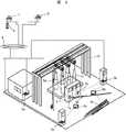
以下、本発明の実施例1を図1から図8により説明する。図1は本実施例の保守支援システムを変電所に適用した場合の保守支援システム構成図、図2は保守支援システムの概略的な機器構成を示す斜視図である。 A first embodiment of the present invention will be described below with reference to FIGS. FIG. 1 is a configuration diagram of a maintenance support system when the maintenance support system of the present embodiment is applied to a substation, and FIG. 2 is a perspective view showing a schematic device configuration of the maintenance support system.
保守支援システムは、図1に示すように、中央制御室に、操作票の表示編集を行うための中央制御装置の端末装置1と、操作票を格納し配信表示機能と操作票実行時に操作の進捗を管理する機能を持つ操作票サーバ2が設置されている。保守センタには、操作票サーバ2とIPネットワーク4を介して接続された監視用の端末装置3が設置されている。端末装置1及び端末装置3は、操作票を画面に表示し、操作手順などの操作パターンを作成・編集する機能と、操作票実行時の監視・承認する機能を有し、端末装置1,3はIPネットワーク4に接続すれば、中央制御室,保守センタ以外の場所でも使用することができ、複数の場所で操作票の作成,編集,操作票の実行,監視を行うことができる。このため、現地,中央制御室,保守センタのそれぞれにおいて操作票の作成,編集,操作票の実行,監視を行うようにすることもできる。 As shown in FIG. 1, the maintenance support system stores in the central control room the
操作現場である変電所には、周辺部の複数箇所に設けられた中継装置設置場所に中継装置5a,5b,5cが設置され、IPネットワーク4を介して操作票サーバ2と接続されている。図2に示す中継装置5は、変電所内に例えば20m毎に間隔で設置され、移動センサ装置6と固定センサ装置7と操作票サーバ2とのデータ通信を仲介する役割を有する。中継装置5には、移動センサ装置6とは後述するアドホックネットワークを構築するための無線通信装置と、操作票サーバ2とはIPネットワーク4を介して通信を行うための通信制御装置を含む通信装置が設けられている。操作票サーバ2との通信にIPネットワーク4を介して接続する例を説明したが、無線通信を用いてもよい。 In a substation as an operation site,
変電所には、送電線から電線を引き込むための鉄塔10が設置され、鉄塔10に引き込まれた電線はブッシング11を介して地下に設けられた変電設備に接続されている。ブッシングの近くには配電盤9が設置されている。変電所の架空内には、移動センサ装置6a,6b,6cが設けられ、配電盤9には固定センサ装置7a,7bが設けられている。この固定センサ装置7は、固定的に設置されるもので変電所内の予め定められた場所に設置される。移動センサ装置6は、作業者が操作する機器のところへ持ち運びして作業する機器の操作状態,チップIDその他を通信するものである。 In the substation, a
図5に示すように、操作票サーバ2は、中継装置5と通信を行う通信制御装置31と、データなどを記憶する記憶装置32と、操作票の処理を制御するCPUなどの制御装置
37と、キーボードなどの入力装置38と、ディスプレイなどの出力装置39が接続バス30で接続された構成になっている。As shown in FIG. 5, the
記憶装置32には、チップIDから固定センサ装置7の設置位置を特定するために用いる情報であるセンサ位置情報DB33と、作業員が変電所で携帯しているモバイル端末装置8に必要な情報を提供する際に、情報を送信すべき中継装置5を特定するための情報である中継装置位置情報DB34と、固定センサ装置7から送信される情報に基づいて変電所に発生した事象を特定するために用いる情報である事象DB35と、作業を行うための操作票DB36が記憶されている。事象DB35には、移動センサ装置6から出力される事象についての信号と、これに対応する事象の内容とが配列されたテーブルである。事象DB35で検出した事象の内容が操作票DB36内に存在した場合に操作票の実施管理を進める。 In the
移動センサ装置6は、図3に示すように、電源モジュール26,制御装置27,無線通信装置28,記憶装置21が接続バス25により接続されて構成されるICチップである。ICチップだけでは通信範囲が小さい場合は、ICチップと無線通信装置とを組み合わせた複合形,電源モジュールを十分大きなものを適用したい場合は、別体形の電源との複合形を用いるが、便宜上これらをまとめて単にICチップという。固定センサ装置7も移動センサ装置6と同様に構成されているICチップである。 As shown in FIG. 3, the movement sensor device 6 is an IC chip configured by connecting a
移動センサ装置6の記憶装置21は、ROM(Read Only Memoryの略) ,RAM(RandomAccess Memory の略)等で構成され、制御用のプログラム,内部スイッチ状態22,作業状態23,チップID24の各データベースが記憶されている。取付けた操作機器を操作して使用状態または停止状態にするが、これらの状態、すなわち内部スイッチ状態は後述するモバイル端末装置8により操作者がICチップである移動センサ装置6に書き込むことにより書き換えられる。内部スイッチ状態22は、その操作状態が記録されている。この内部スイッチ状態22は、制御装置27が作業状態23に応じて判断する際に参照するテーブルである。例えば、作業用機器のフックアースを使用状態に設定した時には、モバイル端末装置8により操作者が書き込むことにより、内部スイッチ状態22が「使用状態」になり、取外す操作をした時点で、内部スイッチ状態22は「未使用状態」になる。 The
電源モジュール26は、移動センサ装置6を駆動する動力源であり、高容量の電池,光を受光して発電する太陽光電池が用いられる。又、変電設備の通電時の振動を利用して発電する発電素子を利用してもよい。制御装置27は、CPU(Central Processing Unitの略)と電子回路等で構成され、移動センサ装置6で実行される各種の処理を制御する。無線通信装置28は、隣接する他の移動センサ装置6,固定センサ装置7,中継装置5と通信を行い、情報の送受信を行う。 The
移動センサ装置6は、図4に示すように、PI/O29を設けてスイッチ状態を取込むようにしてもよい。この場合、移動センサ装置6は、PI/O29により機器のON/
OFFなどの外部接点状態や電圧の有無等の外部センサ状態を取込み、状態変化を内部スイッチ状態22に記録して蓄積し状態変化の内容を送信する。As shown in FIG. 4, the movement sensor device 6 may be provided with a PI /
An external contact state such as OFF or an external sensor state such as the presence / absence of a voltage is taken in, the state change is recorded and stored in the
移動センサ装置6は、作業者が持参して作業対象となる機器の操作を行い、上述したようにモバイル端末装置8により操作者が書き込んだ後、作業対象としている機器に取付けられる。又、移動センサ装置6を単に通信を行うための中継として使用してもよい。この場合は、中継のための通信用であることをモバイル端末装置8により操作者が書き込んでおく。 The movement sensor device 6 is carried by an operator to operate a device to be worked, and after being written by the mobile terminal device 8 as described above, is attached to the device to be worked. Moreover, you may use the movement sensor apparatus 6 as a relay for performing only communication. In this case, the operator writes in the mobile terminal device 8 that the communication is for relay.
変電所に各移動センサ装置6を設置する間隔は、作業機器の種別,周囲環境等により異なるが、1mから10mの範囲に設定される。例えば、設置間隔が10mを超えると、精度が悪くなり位置を特定するのが難しくなる。又、移動センサ装置6間の通信により強い電波を用いる必要であり、装置も大型化するので好ましくない。一方、設置間隔が1mよりも狭いと、モバイル端末装置8との通信でハンドオーバー処理の頻度が増大するので好ましくない。 The interval at which each mobile sensor device 6 is installed at the substation varies depending on the type of work equipment, the surrounding environment, etc., but is set in the range of 1 m to 10 m. For example, when the installation interval exceeds 10 m, the accuracy is deteriorated and it is difficult to specify the position. Further, it is necessary to use a strong radio wave for communication between the mobile sensor devices 6, and the device is also undesirably enlarged. On the other hand, if the installation interval is narrower than 1 m, the frequency of the handover process increases in communication with the mobile terminal device 8, which is not preferable.
移動センサ装置6,固定センサ装置7,中継装置5,モバイル端末8との間には、アドホックネットワークを構築しており、このアドホックネットワークによりデータ通信が行われる。ここで、アドホックネットワークとは、端末同士をピアツーピア接続して一時的なネットワークを構築する無線ネットワーク(マルチホッピングワイヤレスネットワークともいう)のことである。例えば、標準規格IEEE802.11b、あるいはIEEE802.15.1に準拠した無線通信装置に、アドホックルーティングプロトコルであるOLSR(Optimaized Link State Routing の略)を実装して、移動センサ装置6,固定センサ装置7を、センサであると共にルーターであるように動作させてデータをバケツリレー式に伝えることで実現される。 An ad hoc network is constructed among the mobile sensor device 6, the fixed
記憶装置21に格納されているICチップのチップID(チップIdentificationの略)は、移動センサ装置6,固定センサ装置7の個々に割り当てられた番号または記号、もしくはその組み合わで構成される認証用の識別子である。チップIDは、内部スイッチ状態22に格納されている情報に紐付けされて無線通信装置28から送信される。情報を受信した装置は、このチップIDを情報の発信元である移動センサ装置6,固定センサ装置7の設置位置を特定するために用いる。 The chip ID (abbreviation of chip identification) of the IC chip stored in the
通常チップIDには、各移動センサ装置6,各固定センサ装置7毎にそれぞれ固有の
IDを割り振ったものが用いられるが、隣接する複数の移動センサ装置6を1つのグループとして纏め、グループ毎に固有のIDを割り振るようにしてもよい。グループの単位としては、変電所の運用上の単位である電力線の相単位に配設される移動センサ装置6の集合、同電圧階級間でかつ運用する区分毎に設置される設備の集合などである。このようにグループを単位として取扱うことにより、情報の発信元の位置を検索する処理で探索対象の数を減らすことができる。Usually, the chip ID is assigned with a unique ID for each movement sensor device 6 and each fixed
又、チップIDによる管理を行うためには、固定センサ装置7の設置位置を予め確認しておく必要がある。一例としては、変電所工事で固定センサ装置7や中継装置5を設置するときに、チップIDと位置情報とを紐付けして後述するセンサ位置情報データベース
26(以下データベースをDBと略称する)に登録しておく。また、固定センサ装置7を特定位置に設置し、中継装置5に位置検出機能を持たせて、設置された固定センサ装置7からの電波の電界強度を検出して概略位置を検出するようにしてもよい。データベースの作成方法として、位置が確認されている固定センサ装置7からマルチホッピングして送信される移動センサ装置6の情報からチップIDを中継装置5が判別し、判別したチップ
IDに基づいて中継装置5の通信範囲の移動センサ装置6のチップIDの一覧表を作成する。作成したチップIDの一覧表を、データを管理するサーバ装置である操作票サーバ2に送信するようにしてもよい。Further, in order to perform management based on the chip ID, it is necessary to confirm the installation position of the fixed
モバイル端末装置8a,8bは、操作票を画面に表示し作成・編集する機能と、操作票の実行時に進行指示する機能を有する。モバイル端末装置8a,8bを使用して操作票の進行を指示し、操作した結果は、移動センサ装置6a,6b,6cを介して報告される。 The mobile
モバイル端末装置8は、図6に示すように、固定センサ装置7とアドホックネットワークで通信する無線通信装置41と、データなどを記憶する記憶装置42と、モバイル端末装置8の処理を制御するCPUなどで構成される制御装置47と、操作者に情報を伝えるためのディスプレイやスピーカなどの出力手段48と、操作者がモバイル端末装置8を操作するためのボタンなどの入力手段49が接続バス40で接続された構成になっている。 As shown in FIG. 6, the mobile terminal device 8 includes a
記憶装置42には、チップIDから固定センサ装置7の位置を特定するために用いる情報である位置対応表43と、固定センサ装置7から送信される情報に基づいて変電所に発生した事象を特定するために用いる情報である事象DB44と、チップID45,操作票DB46が記憶されている。位置対応表43は、図5に示すセンサ位置情報DB33と同じ内容でも良く、センサ位置情報DB33からそのモバイル端末装置8が近接する可能性のある特定の箇所に設置された移動センサ装置6,固定センサ装置7のセンサIDを抜き出して作成された対応表であっても良い。操作票DB46は、操作票サーバ2で作成・編集された操作票を表示するために使用するデータベースである。 The
このように構成された保守支援システムにおいて、操作者が移動センサ装置6を使用して変電所の作業である機器操作を実施をした場合、モバイル端末装置8を介し操作者に通知するまでの処理の流れを図7に示すフローチャートにより説明する。 In the maintenance support system configured as described above, when the operator uses the movement sensor device 6 to perform the device operation as the work of the substation, the process until the operator is notified via the mobile terminal device 8 The flow will be described with reference to the flowchart shown in FIG.
通常、中央制御室の端末装置1では、複数の機器の操作票を表示画面に表示し、その操作票を参照して該当する操作機器についての操作手順を含む操作パターンを設定する。設定した操作パターンを該当する変電所の中継装置5にIPネットワーク4を介して送信する。中継装置5が受信した操作パターンは、作業者のモバイル端末装置8に送信され、図8に示す作業票として作業者のモバイル端末装置8の表示画面に表示される。操作者は、この表示された作業票の内容を見て、操作機器の操作を行い、モバイル端末装置8により移動センサ装置6に操作状態を書き込み、移動センサ装置6を作業対象機器に取付ける。 Usually, in the
S51で、操作者がモバイル端末装置8により移動センサ装置6bに書き込み、例えば図2に示す移動センサ装置6b内の状態が更新されると、そのタイミングで状態変化を検知する。例えば、操作者の操作により内部スイッチ状態22が変化し、制御装置27が内部スイッチ状態22に変化が起ったことを検知する。S52で、移動センサ装置6は、検知した結果の発生事象を特定する情報と、チップIDと、発生時刻と、ホップ数からなる検出情報を、状態変化検知情報としてアドホックネットワーク上に発信する。ここで、ホップ数とは、アドホックネットワーク上で移動センサ装置6や固定センサ装置7を中継局として通信を行う際に、介在する中継局の数のことを言う。ホップ数は、発信元をゼロとして中継局が介在する毎に1つずつ加算して計数される。 In S51, when the operator writes to the
S53で、ホップ数が予め設定されている設定値か否かの判別を行う。ホップ数が設定値より小さい場合は、S54で、状態変化を検知した移動センサ装置6の周囲に設置されている他の固定センサ装置7は、状態変化情報を受信してホップ数が設定値になるまで、受信した情報を他の近接する固定センサ装置7に送信する。移動センサ装置6は、自己の制御装置27でホップ数を1つ増加してから情報を送信する。ここで、設定値は、センサ装置から発信される情報を少なくとも1つの中継装置5が必ず受信するのに充分なホップ数に設定されている。 In S53, it is determined whether or not the number of hops is a preset value. If the number of hops is smaller than the set value, in S54, the other
このようにして、設定されたホップ数に到達するまで情報はアドホックネットワーク上を伝送される。S55で中継装置5が受信した否かを判別し、アドホックネットワーク上を伝送される過程で中継装置5に受信された場合は、S56で中継装置5は操作票サーバ2に状態変化情報を送信する。中継装置5に受信されていない場合は、S53に戻る。 In this way, information is transmitted over the ad hoc network until the set number of hops is reached. In S55, it is determined whether or not the
S57で、操作票サーバ2では受信したチップIDと、事象DB35と操作票DB36から状態変化を特定する。S58で、操作票DB36に登録されている事象か否かを判別し、操作票DB36に登録されている場合は、S59で操作票DB上正しい状態変化か否かを判断する。これらの結果、正常な操作として認められた場合は、S65で操作票DB36の進捗状態を1つ進め、S66で、操作票DB36を更新する。これらの情報をモバイル端末装置8に送信して表示するようにしてもよい。 In S57, the
S59で、操作票DB36において異常な操作として認められた場合は、S60で操作が異常な旨のメッセージを作成する。S61で、モバイル端末装置8に近隣している中継装置5を特定し、S62で特定した中継装置5に状態変化の通知と操作表状態管理の変化発生を知らせる情報を送信する。 If the
S62で送信された情報は、受信したモバイル端末装置8が、S63で状態変化と操作票による操作とその成否とを判断する。この時、記憶装置42に記憶されている位置対応表43や事象DB44を参照する。仮にモバイル端末装置8が位置対応表43や事象DB44を備えていない場合には、モバイル端末8は、操作票サーバ2もしくは中継装置5に問い合わせて、操作表異常操作の発生位置とその内容を特定する。これらの情報は、S64で、出力手段34により音声や、図8に示す操作票に示されるように文字,画像などの表示により操作者に通知される。 The received mobile terminal device 8 determines the status change, the operation using the operation slip, and the success or failure of the information transmitted in S62. At this time, the position correspondence table 43 and the
本実施例は、変電所に設置された移動センサ装置6により、変電所での状態変化が発生したことを検知して、操作票実施の管理に使用している。このような操作票管理システムは、以下に列挙する応用例にも適用することができる。 In the present embodiment, the movement sensor device 6 installed in the substation detects that a state change has occurred in the substation, and is used for managing operation sheet implementation. Such an operation slip management system can also be applied to the application examples listed below.
例えば、移動センサ装置6に外部PI/Oを設け、分電盤のFFBに取付けて、作業前の状態と作業後の状態が不一致であることを検出した時には作業漏れと判断し、チップ
IDと、検出位置と、検出時刻とを含む情報を送信するようにしても良い。また、アドホックネットワークでデータ通信できない移動センサ装置6や、電波強度が小さくなった移動センサ装置6が発生した場合には、操作票サーバ2において、変電所に落雷等による異常事態がおきたと推定することもできる。For example, an external PI / O is provided in the movement sensor device 6 and attached to the FFB of the distribution board. When it is detected that the state before the work and the state after the work are inconsistent, it is determined that the work is leaked, and the chip ID and Information including the detection position and the detection time may be transmitted. Further, when a mobile sensor device 6 that cannot perform data communication over an ad hoc network or a mobile sensor device 6 with a reduced radio wave intensity occurs, the
このように、実施例1によれば、変電所などの電力系統現場に関する情報の収集や配信を行え、フックアース,工具などの移動可能な機器の個別の現在状態をリアルタイムで監視でき、作業時の場面の状態を管理することができる。又、事前に電子タグを取付けなくても機器の誤操作を防止できる。又、複数の機器を操作する時のヒューマンエラー、操作手順の抜けをシステマチックにチェックして未然に誤操作の発生を防止できる。又、変電所に実装したセンサ装置と監視装置の間で情報をIPネットワークで送受信するようにしたので、比較的に低額な通信料で、充分な通信速度を確保することができる。通信用に設定した移動センサ装置も設置して、通信装置を変電所内に分散させアドホックネットワークを形成しているので、各センサ装置,中継装置の通信状態を良好にできる。 As described above, according to the first embodiment, it is possible to collect and distribute information related to a power system site such as a substation, and to monitor an individual current state of a movable device such as a hook ground and a tool in real time. You can manage the state of the scene. Further, it is possible to prevent erroneous operation of the device without attaching an electronic tag in advance. In addition, it is possible to systematically check for human errors and missing operating procedures when operating a plurality of devices, thereby preventing erroneous operations. In addition, since information is transmitted and received between the sensor device and the monitoring device mounted in the substation via the IP network, a sufficient communication speed can be ensured with a relatively low communication fee. Since the mobile sensor device set for communication is also installed and the communication device is distributed in the substation to form an ad hoc network, the communication state of each sensor device and relay device can be improved.
本発明の実施例2を図9により説明する。図9は、本実施例の保守支援システムを変電所に適用した場合の保守支援システム構成図である。 A second embodiment of the present invention will be described with reference to FIG. FIG. 9 is a configuration diagram of a maintenance support system when the maintenance support system of the present embodiment is applied to a substation.
本実施例の保守支援システムは、変電所に設置された複数のセンサ装置を用いて、長い工期のうちの操作されない状態を含む操作状態に合わせたサービスを、操作者毎に提供することを目的としている。本実施例の保守支援システムは、変電所に設置された複数の固定センサ装置7と、固定センサ装置7からの情報を無線通信により受信する中継装置5と、モバイル端末装置8で構築されるアドホックなセンサネットワークと、中継装置5からの情報を受信して変電所の管理を行う変電所管理サーバ13とを含んで構成される。 The maintenance support system according to the present embodiment aims to provide a service for each operator according to an operation state including a state in which a long operation period is not operated using a plurality of sensor devices installed in a substation. It is said. The maintenance support system of the present embodiment is an ad hoc constructed by a plurality of fixed
センサ装置12は、自己のチップIDと、自己の情報と、ホップ数とを変電所情報として送信する。センサ装置12は、工具に取付けられており、持ち込まれた作業機器の個々を区別して工具をモバイル端末装置8で管理して撤去忘れないように検知,誘導するためにセンサ情報と工具情報が付加されている。 The
中継装置5は、アドホックネットワークを利用して送信される各センサ装置12からの位置情報を変電所管理サーバ13に送信し、変電所管理サーバ13から送られくる情報をモバイル端末装置8に送信する。 The
図10に示すように、変電所管理サーバ13は、中継装置5とデータ通信を行う通信制御装置71と、データなどを記憶する記憶装置72と、変電所管理サーバ13の処理を制御するCPUなどの制御装置75と、キーボードなどの入力装置77と、ディスプレイなどの出力装置76で構成されている。 As shown in FIG. 10, the
記憶装置72には、変電所毎の設備スペースの大きさや危険状況などを特定する情報である変電所DB73と、センサ装置12の所有者を特定するための情報である装置グループDB74が記憶されている。変電所DB73は、変電所内のある位置と、変電所内の設置された固定センサ装置7のチップID及びその設置位置と、変電所の利用状態と、作業期間等の作業情報などで構成されている。ここで、変電所の利用状態とは、例えば、変電所を平面的に表した場合に作業者が作業している領域と、作業者が作業していない領域でかつセンサ装置12が置かれていることが不自然な領域とを特定したマップによって示されるものがある。 The
又、変電所の設備の充電状態/停電状態が変化したタイミングで、操作者のモバイル端末装置8に危険情報が変化したことを同報メッセージとして伝え、表示するようにしてもよい。又、変電所の設備の危険区域を区分して、操作者が、担当の作業区分から外れて作業範囲外の区域に立ち入ったタイミングで、作業範囲外の区域に立ち入った情報を、作業者のモバイル端末装置8,管理責任者のモバイル端末装置8に伝え表示して、立ち入った作業者と管理責任者に通知するメッセージサービスを行うようにしてもよい。 Further, at the timing when the charging state / power failure state of the substation equipment changes, the operator's mobile terminal device 8 may be notified of the change of the danger information as a broadcast message and displayed. Also, by dividing the hazardous area of the substation equipment, the operator enters the area outside the work area at the timing when the operator departs from the work area in charge and enters the area outside the work area. A message service may be provided in which the mobile terminal device 8 and the manager's mobile terminal device 8 are informed and displayed to notify the worker and the manager in charge.
このように、実施例2によれば、持ち込まれた作業機器の撤去忘れを防止することができる。又、個々の作業者に危険情報や作業範囲外の区域に立ち入った情報を提供できる。 Thus, according to the second embodiment, it is possible to prevent forgetting to remove the work equipment brought in. Also, it is possible to provide danger information and information that has entered an area outside the work range to individual workers.
1,3…端末装置、2…操作票サーバ、4…ネットワーク、5…中継装置、6…移動センサ装置、7…固定センサ装置、8…モバイル端末装置、9…配電盤、10…鉄塔、11…ブッシング、12…センサ装置、13…変電所管理サーバ。
DESCRIPTION OF
Claims (5)
Translated fromJapaneseDBと、該当する操作機器についての操作手順を含む操作パターンを含む操作票DBを記憶する記憶装置と、操作票の処理を制御する制御装置と、変電所に設置された中継装置と通信を行う通信制御装置とを備え、前記制御装置は、前記通信制御装置より操作パターンをモバイル端末に送信して前記モバイル端末により移動センサに書き込まれた作業状態、移動センサのIDチップを受信し、前記事象DBと操作票DBから状態変化を特定して前記操作票DB上正しい状態変化か否かを判断し、作業票の進捗状態を管理するサーバ。A sensor position information DB, which is information for specifying a fixed sensor position from a chip ID, and a relay device to which information is transmitted when an operator provides necessary information to a mobile terminal device carried at a substation Relay device location information DB that is information for identifying the event, event DB that is information used to identify an event that has occurred in the substation based on information transmitted from the fixed sensor, and the corresponding operation device A storage device that stores an operation slip DB including an operation pattern including an operation procedure, a control device that controls processing of the operation slip, and a communication control device that communicates with a relay device installed in a substation; The apparatus transmits the operation pattern from the communication control apparatus to the mobile terminal and receives the work state written in the movement sensor by the mobile terminal and the ID chip of the movement sensor. The event DB and the operation form to identify the state change from DB to determine whether the operation form DB on the correct state change, to manage the progress of the work ticket server.
The substation management server identifies and indicates a region where an operator is working on the mobile terminal device and a region where it is unnatural that a sensor device is placed in a region where the worker is not working The maintenance support system according to claim 3.
Priority Applications (1)
| Application Number | Priority Date | Filing Date | Title |
|---|---|---|---|
| JP2005110452AJP2005293600A (en) | 2005-04-07 | 2005-04-07 | Maintenance support system and server |
Applications Claiming Priority (1)
| Application Number | Priority Date | Filing Date | Title |
|---|---|---|---|
| JP2005110452AJP2005293600A (en) | 2005-04-07 | 2005-04-07 | Maintenance support system and server |
Related Parent Applications (1)
| Application Number | Title | Priority Date | Filing Date |
|---|---|---|---|
| JP2003402362ADivisionJP3684366B2 (en) | 2003-12-02 | 2003-12-02 | Maintenance support system |
Publications (1)
| Publication Number | Publication Date |
|---|---|
| JP2005293600Atrue JP2005293600A (en) | 2005-10-20 |
Family
ID=35326386
Family Applications (1)
| Application Number | Title | Priority Date | Filing Date |
|---|---|---|---|
| JP2005110452APendingJP2005293600A (en) | 2005-04-07 | 2005-04-07 | Maintenance support system and server |
Country Status (1)
| Country | Link |
|---|---|
| JP (1) | JP2005293600A (en) |
Cited By (7)
| Publication number | Priority date | Publication date | Assignee | Title |
|---|---|---|---|---|
| JP2007257207A (en)* | 2006-03-22 | 2007-10-04 | Fujitsu Ltd | Work support system, work support device, and computer program |
| JP2019071090A (en)* | 2013-03-15 | 2019-05-09 | フィッシャー−ローズマウント システムズ,インコーポレイテッド | Method and device for controlling process plant by location-aware mobile control device |
| US10866952B2 (en) | 2013-03-04 | 2020-12-15 | Fisher-Rosemount Systems, Inc. | Source-independent queries in distributed industrial system |
| US10909137B2 (en) | 2014-10-06 | 2021-02-02 | Fisher-Rosemount Systems, Inc. | Streaming data for analytics in process control systems |
| US11385608B2 (en) | 2013-03-04 | 2022-07-12 | Fisher-Rosemount Systems, Inc. | Big data in process control systems |
| US11886155B2 (en) | 2015-10-09 | 2024-01-30 | Fisher-Rosemount Systems, Inc. | Distributed industrial performance monitoring and analytics |
| JP2024516209A (en)* | 2021-04-26 | 2024-04-12 | ヒタチ・エナジー・リミテッド | Monitoring system for an electric power transmission and/or distribution network - Patents.com |
- 2005
- 2005-04-07JPJP2005110452Apatent/JP2005293600A/enactivePending
Cited By (10)
| Publication number | Priority date | Publication date | Assignee | Title |
|---|---|---|---|---|
| JP2007257207A (en)* | 2006-03-22 | 2007-10-04 | Fujitsu Ltd | Work support system, work support device, and computer program |
| US10866952B2 (en) | 2013-03-04 | 2020-12-15 | Fisher-Rosemount Systems, Inc. | Source-independent queries in distributed industrial system |
| US11385608B2 (en) | 2013-03-04 | 2022-07-12 | Fisher-Rosemount Systems, Inc. | Big data in process control systems |
| JP2019071090A (en)* | 2013-03-15 | 2019-05-09 | フィッシャー−ローズマウント システムズ,インコーポレイテッド | Method and device for controlling process plant by location-aware mobile control device |
| US11112925B2 (en) | 2013-03-15 | 2021-09-07 | Fisher-Rosemount Systems, Inc. | Supervisor engine for process control |
| US11169651B2 (en) | 2013-03-15 | 2021-11-09 | Fisher-Rosemount Systems, Inc. | Method and apparatus for controlling a process plant with location aware mobile devices |
| US11573672B2 (en) | 2013-03-15 | 2023-02-07 | Fisher-Rosemount Systems, Inc. | Method for initiating or resuming a mobile control session in a process plant |
| US10909137B2 (en) | 2014-10-06 | 2021-02-02 | Fisher-Rosemount Systems, Inc. | Streaming data for analytics in process control systems |
| US11886155B2 (en) | 2015-10-09 | 2024-01-30 | Fisher-Rosemount Systems, Inc. | Distributed industrial performance monitoring and analytics |
| JP2024516209A (en)* | 2021-04-26 | 2024-04-12 | ヒタチ・エナジー・リミテッド | Monitoring system for an electric power transmission and/or distribution network - Patents.com |
Similar Documents
| Publication | Publication Date | Title |
|---|---|---|
| US20080109099A1 (en) | Apparatus and method for process control using people and asset tracking information | |
| US20080109098A1 (en) | Apparatus and method for integrating people and asset tracking information into a process control system | |
| CN114330764B (en) | Operation ticket processing method and device, storage medium and electronic device | |
| JP5013935B2 (en) | Work target notification system and work target notification server | |
| CN106384303A (en) | Distribution room operation and maintenance management system and method | |
| CN103021142A (en) | Remote warning system of engineering machinery device and control method of remote warning system | |
| CN202659281U (en) | Comprehensive monitoring system for mining equipment communication | |
| CN102590707A (en) | Cable monitoring system based on GPRS (general packet radio service) | |
| JP2005293600A (en) | Maintenance support system and server | |
| JP2011048493A (en) | Locating system | |
| CN202486264U (en) | Cable monitoring system based on general packet radio service (GPRS) | |
| JP3684366B2 (en) | Maintenance support system | |
| JP5033774B2 (en) | Railway maintenance work management system | |
| JP2011108112A (en) | Maintenance supporting system and maintenance supporting method | |
| CN108415387A (en) | A kind of safety control system and method for controlling security | |
| KR20210107587A (en) | An Apparatus for Monitering a Distribution Panel Board | |
| CN209765059U (en) | Beidou positioner based on RFID control | |
| CN104734357B (en) | The one-touch communication loop method of calibration of Intelligent substation merging unit | |
| JP4419065B2 (en) | Device for preventing operation of unqualified personnel on work machines | |
| JP4274992B2 (en) | Distribution automation system and power outage construction management method | |
| CN109660974A (en) | Intelligent escape evacuating system for power station | |
| CN208166254U (en) | A kind of lift management system | |
| CN114205688A (en) | Intelligent supervision system and method | |
| CN109039783B (en) | Alarm method and device | |
| CN111899372A (en) | Man-machine interactive management system |
Legal Events
| Date | Code | Title | Description |
|---|---|---|---|
| RD04 | Notification of resignation of power of attorney | Free format text:JAPANESE INTERMEDIATE CODE: A7424 Effective date:20060425 | |
| A131 | Notification of reasons for refusal | Free format text:JAPANESE INTERMEDIATE CODE: A131 Effective date:20071016 | |
| A521 | Request for written amendment filed | Free format text:JAPANESE INTERMEDIATE CODE: A523 Effective date:20071213 | |
| A131 | Notification of reasons for refusal | Free format text:JAPANESE INTERMEDIATE CODE: A131 Effective date:20080115 | |
| A521 | Request for written amendment filed | Free format text:JAPANESE INTERMEDIATE CODE: A523 Effective date:20080313 | |
| A02 | Decision of refusal | Free format text:JAPANESE INTERMEDIATE CODE: A02 Effective date:20080415 |